Lifestyler 831297530 User Manual SM 1100 TREADMILL Manuals And Guides 99020108
LIFESTYLER Treadmill Manual 99020108 LIFESTYLER Treadmill Owner's Manual, LIFESTYLER Treadmill installation guides
User Manual: Lifestyler 831297530 831297530 LIFESTYLER LIFESTYLER SM 1100 TREADMILL - Manuals and Guides View the owners manual for your LIFESTYLER LIFESTYLER SM 1100 TREADMILL #831297530. Home:Fitness Equipment Parts:Lifestyler Parts:Lifestyler LIFESTYLER SM 1100 TREADMILL Manual
Open the PDF directly: View PDF ![]() .
.
Page Count: 20

1OOO
MAKER
8£/,4R8
Model No. 831.297530
Serial No.
The sedaJ number can be found in the
location shown below. Write the serial
number in file space above.
erial Number Decal
F"O U i _M_" NT
HELPLINE!
1-800-736-6879
_i_CAUTION
' Read all i_eca_lo_°and Insb'uc-'
for_ _
USER'S MANUAL
SEARS, ROEBUCK AND CO., HOFFMAN ESTATES, IL 60179
2
IFULL 90 DAY WARRANTY I
For 90 days from the date of purchase, If failure occurs due to defect in material or workmanship in this
SEARS TREADMILL EXERCISER, contact the nearest SEARS Service Center throughout the United
States and SEARS will repair or replace the TREADMILL EXERCISER, free of charge.
Thiswarrantydoesnot applywhentheTREADMILLEXERCISER isusedcommerciallyorfor rentalpup
poses.
This warranty gives you sped_ legal rights, emdyou may also have other dgh_ _ _ _ s_te
to state.
SEARS, ROEBUCK AND CO., DEPT. 817WA, HOFFMAN ESTATES, IL 60179

- SPACE. 4
- o-.OOO
TABLE OF CONTENTS
FULL 90 DAY WARRANTY ..............................................................
IMPORTANT PRECAUTIONS ............................ ...............................
BEFORE YOU BEGIN ..................................................................
ASSEMBLY .............................................................
OPERATION AND ADJUSTMENT ...........................................
HOW TO FOLD AND MOVE THE TREADMILL .................................
TROUBLE-SHOOTING ....................................................
,.ooo.2
°o**oo4
°oeoo°5
,,°ooo°oo°=,,o°oo°6
o,ooooo,=J°Jooo,°o7
•,.o °o ....... ,o°°10
• ....... o.°o ..... 12
CONDITIONING GUIDELINES ............................................................... 14
ORDERING REPLACEMENT PARTS .................................................. Back Cover
Note: An EXPLODED DRAWING and a PART LIST are attached to the center of this manual. Save the
EXPLODED DRAWING and PART LIST for future reference.
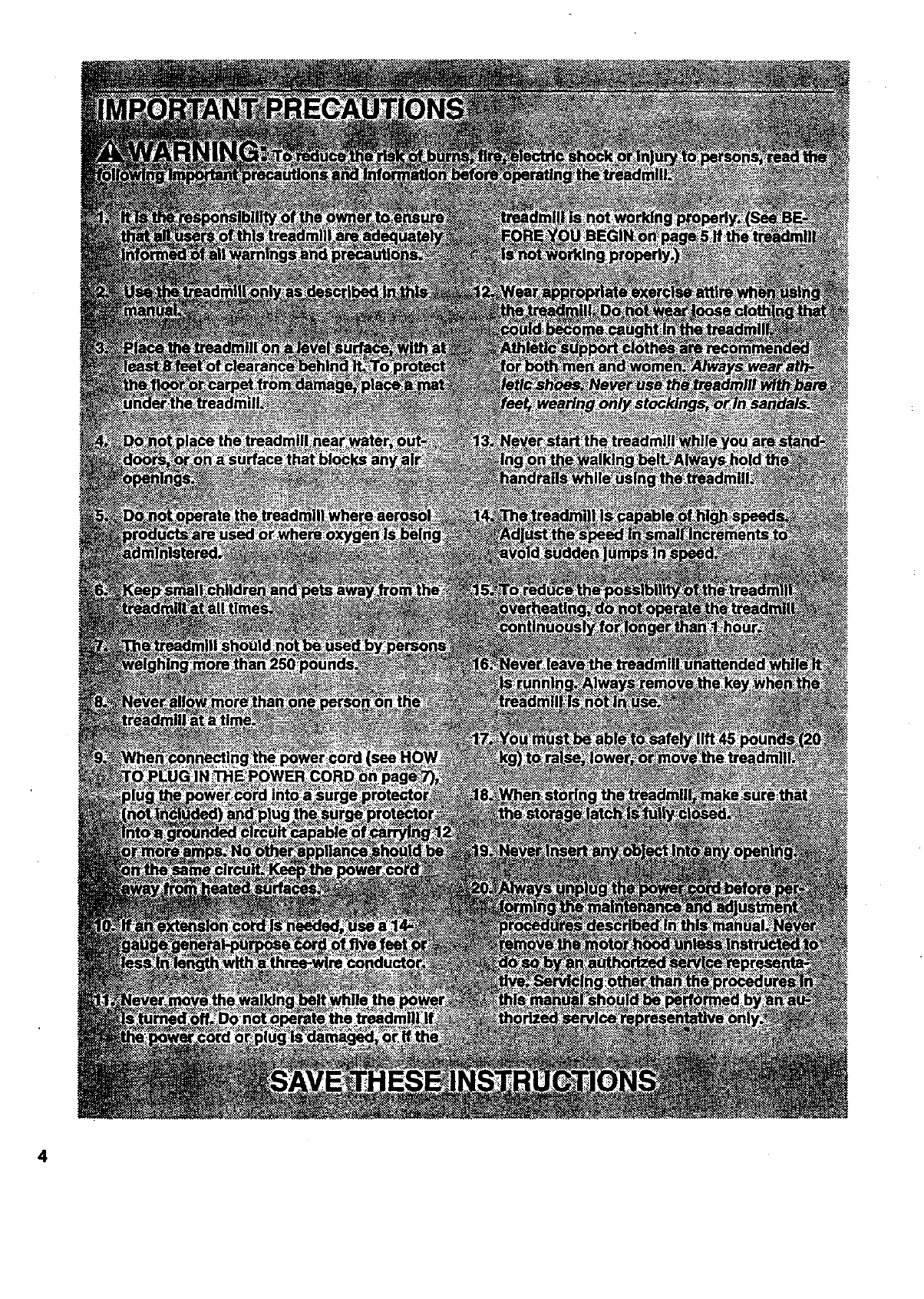
"_A'3LAIADMIMd_-, _,. _.." ' "..,:_.':"...::.:_..:_.._'_.':_.,.__'_: _ _ .....
n,,_,_ ,!mp_,_tfo,_,_, a_ _0_!____
Read all instructions before using. SEARS m_n0__
damage sustained byor through the use Of this product. _ ::: ;_!'_:.
3
4
BEFORE YOU BEGIN
Thank you for selecting the unique SEARS_ SPACE
MAKER 1000 LS treadmill. The SPACE MAKER 1000
LS treadmill blends advanced technology with innova-
tive stylingto let you enjoy an excellent form of cardio-
vascular exercise in the convenience and privacy of
your home. The SPACE MAKER 1000 LS offers an im-
pressive array of features to make your workouts more
enjoyable and effective. And when you're not exercis-
Ing, the SPACE MAKER 1000 LS can be folded up, re-
quiring less than half the floor space of other treadmills.
For your benefit, read this manual carefully before
using the treadmill. If you have additional questions,
please call our toll-free HELPLINE at 1-800-736-6879,
Monday through Saturday, 7 a.m. until 7 p.m. Central
Time (excluding holidays). To help us assist you,
please note the product model number and serial num-
ber before calling. The model number of the treadmill
is 831.297530. The sedal number can be found on a
decal attached to the treadmill (sea the front cover of
this manual for the location).
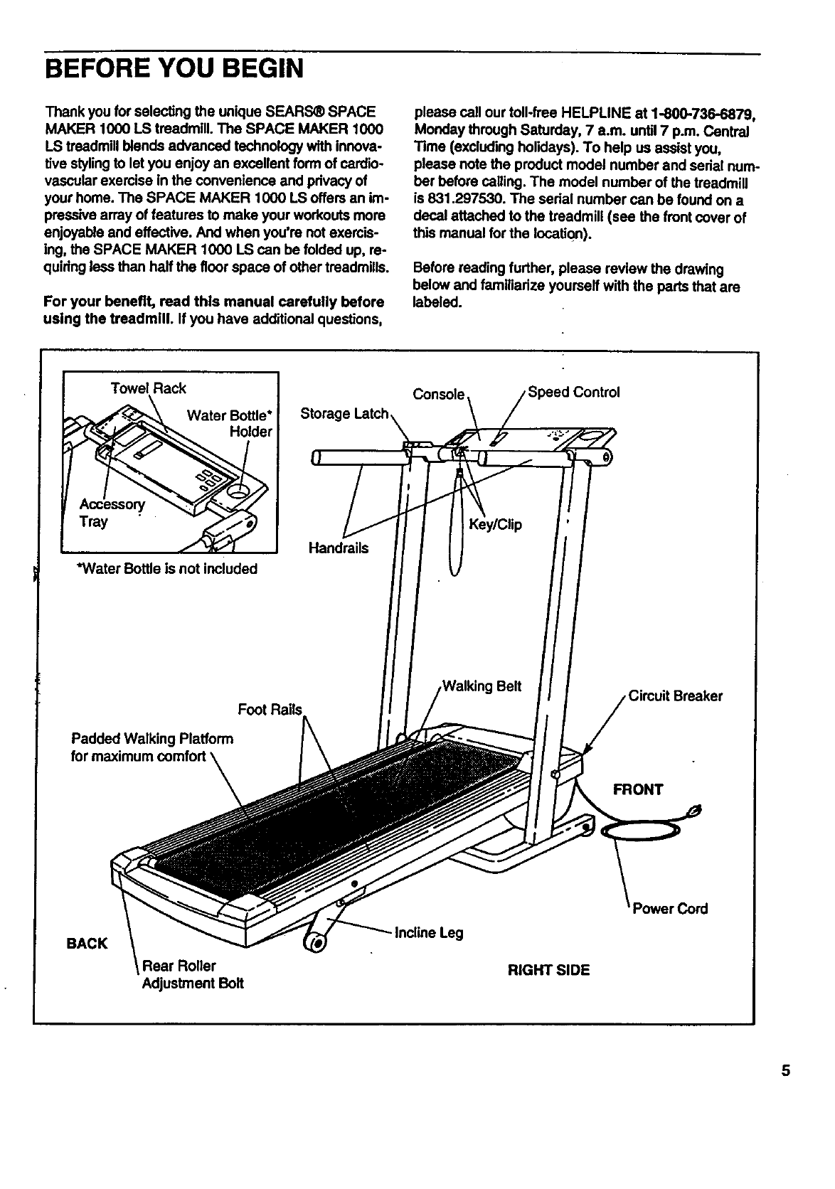
Before reading further, please review the drawing
below and familiarize yourself with the parts that are
labeled.
Towel Rack
Water Bottle*
Holder
Tray
*WaterBottleis notincluded
Console /Speed Control
Storage Latch\ \/
Foot Rails
Padded Walking Platform
for maximum comfort \
\FRONT
BACK
Rear Roller
Adjustment Belt
- Incline Leg
RIGHT SIDE
3ord
5
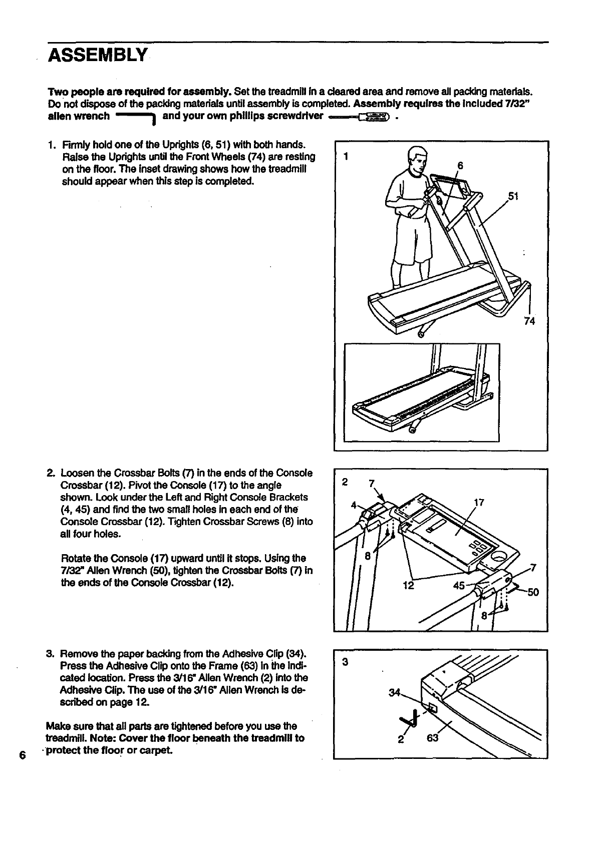
ASSEMBLY
Tw opeople am requirecl for assembly. Set the treadmill in a deared area and remove all packing matedals.
Do not dispose of the pecking materials untilassembly is completed. Assembly requires the Included 7/32"
allen wrench _and your own phillips screwdriver ,=-=---=,,C_J_) •
1. Rrmly hold one of the Uprights (6, 51) with both hands.
Raise the Updghts until the Front Wheels (74) are resting
on the floor. The inset drawing shows how the treadmill
should appear when this step is completed.
6
74
tLoosen the Crossbar Bolts (7) in the ends of the Console
Crossbar (12). Pivot the Console (17) to the angle
shown. Look under the Left and Right Console Brackets
(4, 45) and find the two small holes in each end of the
Console Crossbar (12). Tighten Crossbar Screws (8) into
all four holes.
Rotate the Console (17) upward until it stops. Using the
7/32" Allen Wrench (50), tighten the Crossbar Bolts (7) in
the ends of the Console Crossbar (12).
2 7
17
6
3. Remove the paper backing from the Adhesive Cflp (34).
Press the Adhesive Clip onto the Frame (63) in the Indi-
cated location. Press the 3/16" Allen Wrench (2) Into the
Adhesive Clip. The use of the 3/16" Allen Wrench is de-
scdbed on page 12.
Make sure that all perts are tightened before you use the
treadmill. Note: Cover the floor beneath the treadmill to
•protect the floor or carpel
3
63
--OPERATIONAN DADJUSTMENT
THE PERFORMANT LUBE TM WALKING BELT
Your treadmill features a walking belt coated with
PERFORMANT LUBE TM, a high-performance lubricant.
Dudng the first few hours of use, it is normal for a
small amount of white powder to appear on the foot
rails and the walking platform. The white powder Is ex-
cess high-performance lubdcant from the walking belt.
IMPORTANT: Never apply slllcone spray or other
substances to the walking belt or the walking plat-
form. They wlll deterlorate the walking belt and
cause excessive wear.
HOW TO PLUG IN THE POWER CORD
This product must be grounded. If it should malfunc-
tion or break down, grounding provides a path of least
resistance for electdc current to reduce the dsk of elec-
tric shock. This product Is equipped with a cord having
an equipment-grounding conductor and a grounding
plug. Plug the power cord Into asurge protector,
and plug the surge protector into an appropriate
outlet that Is properly Installed and grounded in
accordance with all local codes and ordinances.
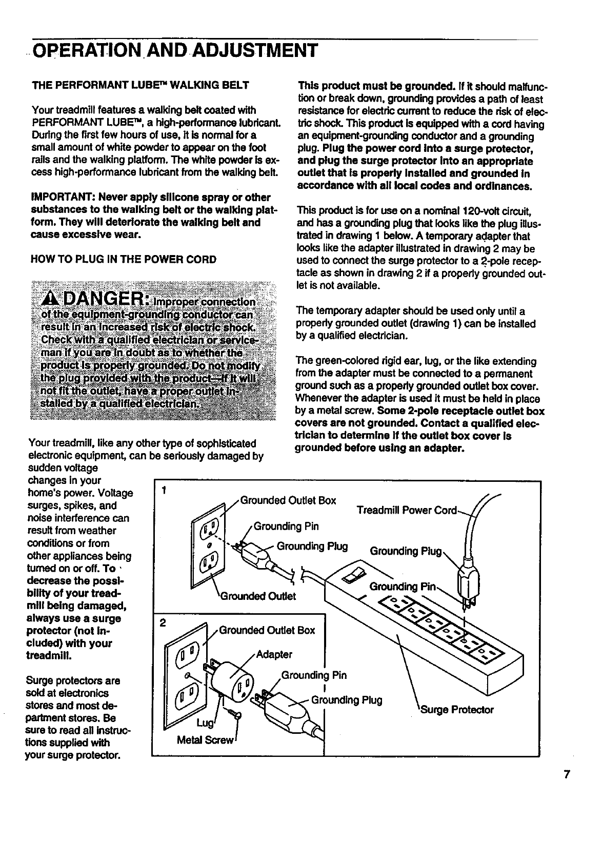
This product is for use on a nominal 120-volt cimuit,
and has a grounding plug that looks like the plug illus-
trated in drawing 1 below. A temporary adapter that
looks like the adapter illustrated in drawing 2 may be
used to connect the surge protector to a2.-pole recap-
tacle as shown in drawing 2 if a properly grounded out-
let is not available.
The temporary adapter should be used only untila
propedy grounded outlet (drawing 1) can be installed
by a qualified electrician.
Your treadmill, like any other type of sophisticated
electronic equipment, can be seriously damaged by
sudden voltage
changes in your
home's power. Voltage
surges, spikes, and
noise interference can
result from weather
conditions or from
other appliances being
fumed on or off. To '
decrease the possi-
bility of your tread-
mill being damaged,
always use a surge
protector (not In-
cluded) with your
treadmill
Surge protectors are
sold at electronics
stores and most de..
partment stores. Be
sure to read all instruc-
tions supplied with
your surge protector.
The green-colored dgid ear, lug, or the like extending
from the adapter must be connected to a permanent
ground such as a properly grounded outlet box cover.
Whenever the adapter is used it must be held in place
by a metal screw. Some 2-pole receptacle outlet box
covers are not grounded. Contact aqualified elec-
trician to determine if the outlet box cover Is
grounded before using an adapter.
_Grounded Outlet Box
I _,J /Grounding Pin
'_rounding Plug
_Grounded Outlet
_,__. ,Grounded Outlet Box I
/Adapter I
/,_ __Grounding Pin
,
/'T_ _'r,_"_ "_ Grounding Plug
Metal __rew I
'Surge Protector
7
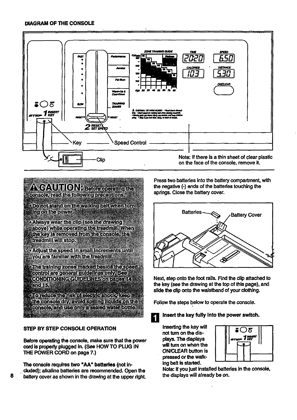
DIAGRAM OF THE CONSOLE
I°
Speed Control
Note: If there is a thin sheet of clear plastic
on the face of the console, remove iL
Press two battedes into the battery compartmenL with
the negative (-) ends of the battados touching the
spdngs. Close the battery cover.
8
STEP BY STEP CONSOLE OPERATION
Before operating the console, make sure that the power
cord Is properly plugged in. (See HOW TO PLUG IN
THE POWER CORD on page 7.)
The console requires two "AA" batteries (not in-
.duded); alkaline bettedes are recommended. Open the
battery cover as shown in the drawing at the upper dghL
Next, step onto the foot roils. Find the clip attached to
the key (see the drawing at the top of this page), and
slide the clip onto the waistband of your clothing.
Follow the steps below to operate the console.
Ii1 Insert the key fully Into the power switch.
Inserting the key will
not tum on the dis-
plays. The displays
will tum on when the
ON/CLEAR button is
pressed or the walk-
ing belt is started.
Note: If you just installed batteries In the console,
the displays will already be on.
Reset the speed control and start the walking.
B belL
Slide the speed control down
to the "RESET" position.
Note: Each time the walk-
Ing belt is stopped, the
speed control must be
moved to the "RESET" po-
sition before the walking
belt can be restarted. Next,
slide the control up untilthe
walking belt begins to move
at slow speed.
.,...- rle -__
Iu
I•
i •
i o
mwi_a
Carefully step onto the walking belt and begin exer-
cising. Change the speed of the walking belt as de-
sired by sliding the speed control.
To stop the walking belt, step onto the foot rails and
slide the speed control to the "RESET' position.
B Follow your progress with the four monitor dls-
plays.
The monitor displays provide the following exercise
feedback:
• TIME
This display shows TIME
the total time that
the walking belt
has been moving.
Note: When the
walking belt is
stopped, the TIME display will pause after a few
seconds.
[_3 ml
LLI'L LI J
•CALORIES
This display shows
the approximate CALORIES
number of Calodes
you have burned.
Note: The actual .....
number of Calodes
you bum may differ slightly from the number dis-
played if the speed and incline are near the highest
or lowest settings.
•SPEED
the speed.of the SPEEO
walking belt, In
miles per hour.
• DIS'rANCE_
This display
shows the total
distance that you
have walked or
ran, in miles.
DISTANCE
li" n
Note: The displays
can be reset, if de-
sired, by pressing
the ON/CLEAR but-
ton.
I
B When you are finished exercising, stop the walk-
Ing belt and remove the key.
Step onto the foot
mils, stop the walk-
ing belt, and remove
the key from the con-
sole. Keep the key in
a safe place.
Note: After the key is removed, the displays will
remain on for about four minutes.
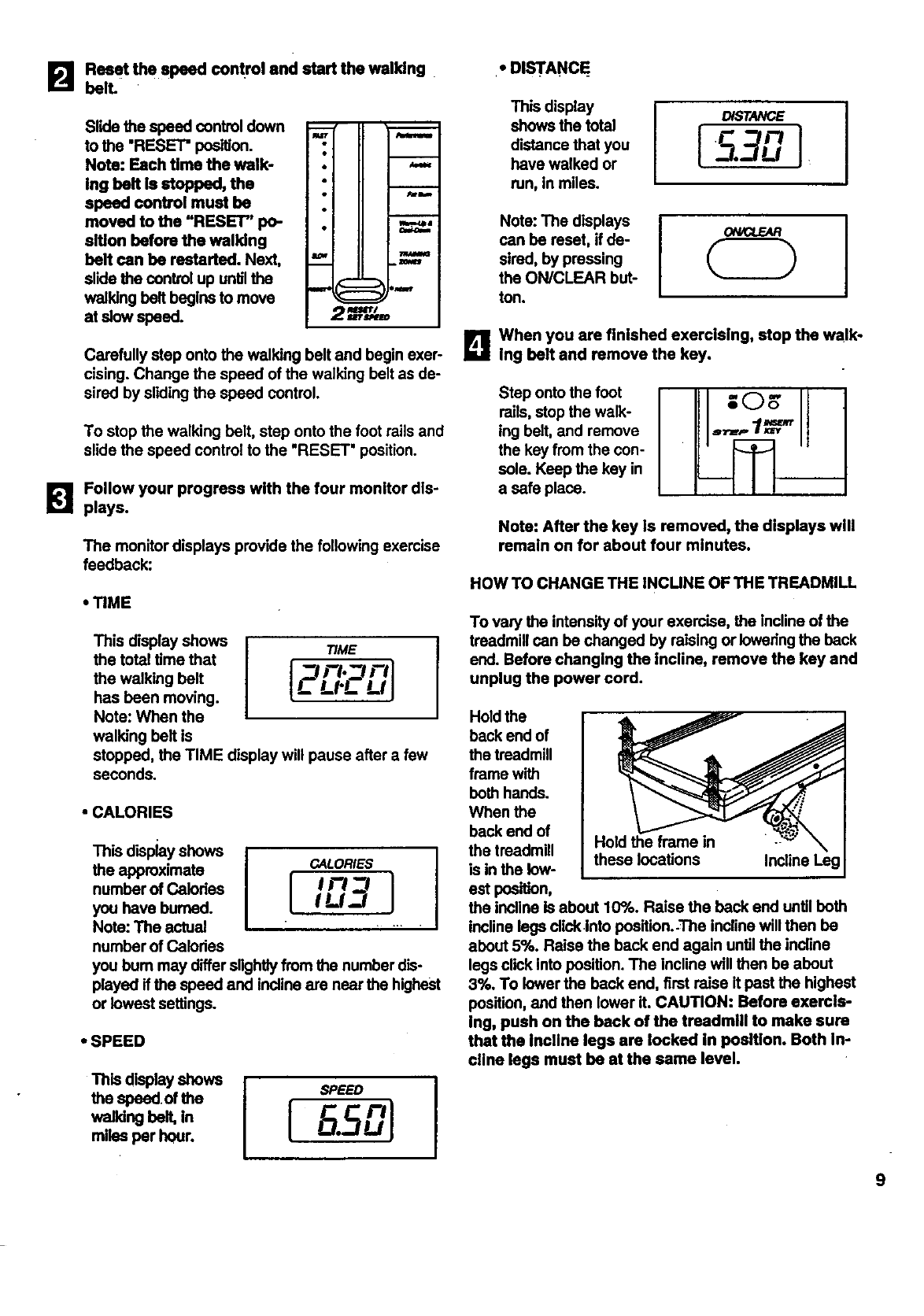
HOW TO CHANGE THE INCUNE OF THE TREADMILL
To vary the intensity of your exercise, the incline of the
treadmill can be changed by raising or Iowedng the beck
end. Before changing the incline, remove the key and
unplug the power cord.
Hold the frame in
these locations Incline Leg
Hold the
back end of
the treadmill
frame with
beth hands.
When the
back end of
the treadmill
is in the low-
est position,
the incline Is about 10%. Raise the back end until beth
incline lags clickinto position.-The incline will then be
about 5%. Raise the back end again until the indine
legs click into position. The incline will then be about
3%, To lower the back end, first raise it pest the highest
position, and then lower it. CAUTION: Before exercls-
Ing, push on the back of the treadmlll to make sure
that the Incllne legs are locked In position. Both In-
cllne legs must be at the same level.
9
HOW TO FOLD AND MOVE THETREADMILL
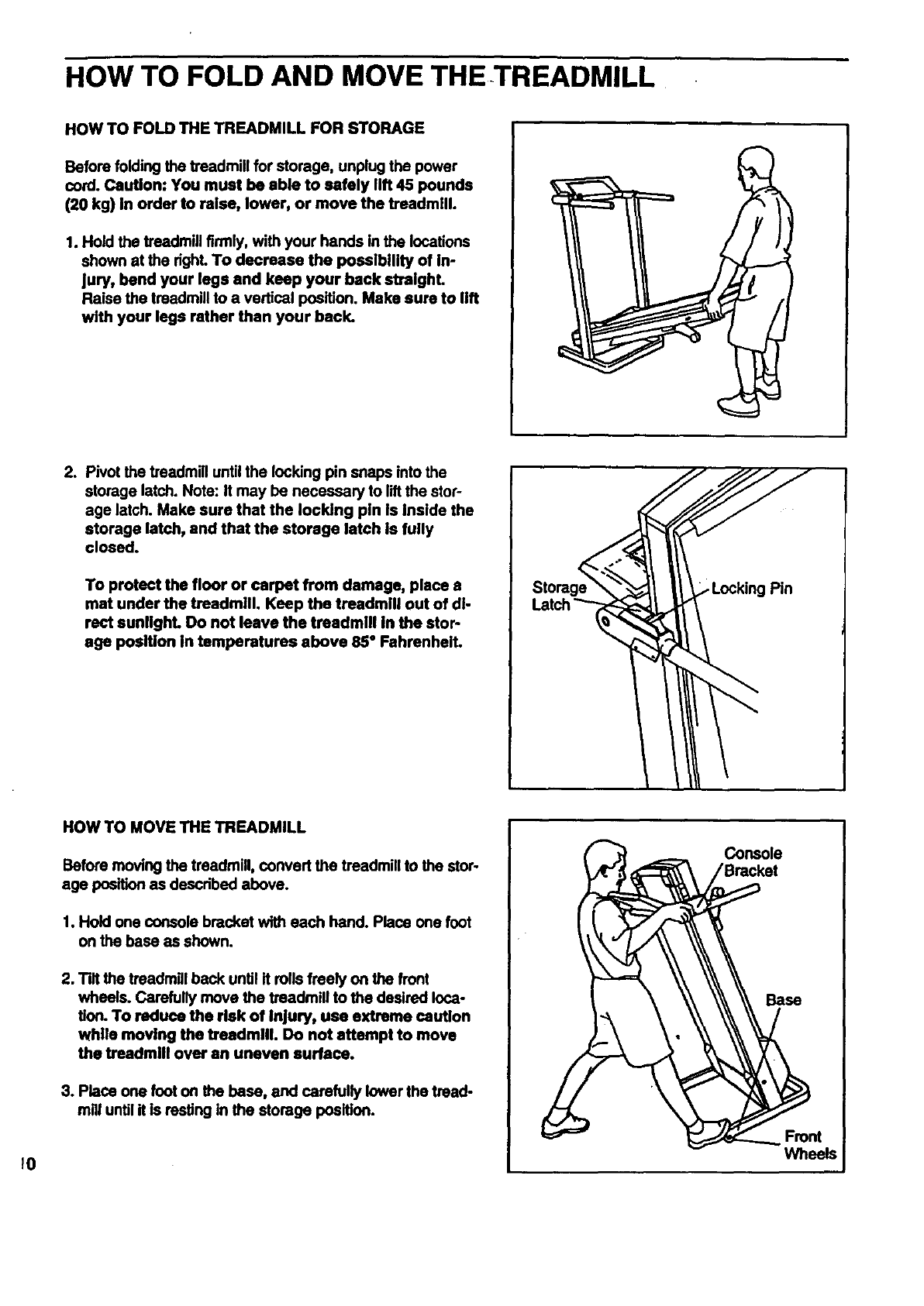
HOW TO FOLD THE TREADMILL FOR STORAGE
Before folding the treadmill for storage, unplug the power
cord. Caution: You must be able to safely lift 45 pounds
(20 kg) in order to raise, lower, or move the treadmill.
1. Hold the treadmill firmly, with your hands in the locations
shown at the right. To decrease the possibility of in-
Jury, bend your legs and keep your back streighL
Raise the treadmill to a vertical position. Make sure to lift
with your legs rather than your back.
2, Pivot the treadmill until the locking pin snaps into the
storage latch. Note: It may be necessary to liftthe stop
age latch. Make sure that the locking pin Is Inside the
storage latch, and that the storage latch is fully
closed.
To protect the floor or carpet from damage, place s
mat under the treadmill. Keep the treadmill out of di-
rect sunlighL Do not leave the treadmill In the stop
age position in temperatures above 85" Fahrenheit.
Pin
10
HOW TO MOVE THE TREADMILL
Before moving the treadmill, convert the treadmill to the stop
age position as described above.
1. Hold one console bracket with each hand. Place one foot
on the base as shown.
2. Tilt the treadmill back until it rolls freely on the front
wheels. Carefully move the treadmill to the desired loca-
tion. To reduce the risk of Injury, use extreme caution
while moving the treadmill. Do not attempt to move
the treadmill over an uneven surface.
3. Place one foot on the base, and carefully lower the tread-
mill untilit is resting in the storage position.
Console
Base
Wheels
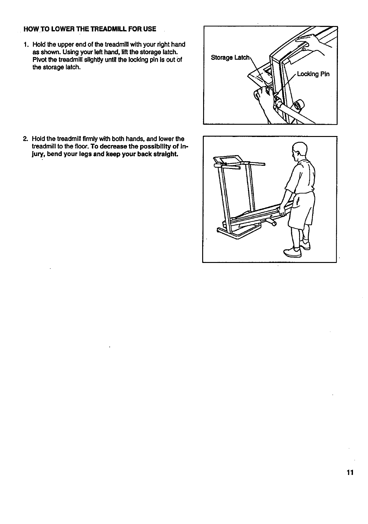
HOW TO LOWER THE TREADMILL FOR USE
1. Hold the upper end of the treadmill with your right hand
as shown. Using your left hand, liftthe storage latch.
Pivot the treadmill slightly until the locking pin is out Of
the storage latch.
Storage
2. Hold the treadmill firmly with both hands, and lower the
treadmill to the floor. To decrease the possibility of in-
Jury, bend your legs and keep your back straight.
11
TROUBLE-SHOOTING
Most treedmill problems can be solved by following the simple steps below. Find the symptom that ap-
pltss, and follow the steps listed. If further assistance Is needed, call our toll-free HELPLINE st 1-800-736-
6879, Monday through Saturday, 7 a.m. until 7p.m. Central Time (excluding holidays).
1. SYMPTOM: THE POWER DOES NOT TURN ON
a. Make sure that the power cord is plugged into a surge protector, and that the surge protector is plugged into
aproperly grounded oultet. (See HOW TO PLUG IN THE POWER CORD on page 7.) If an extension cord is
needed, use only a 14-gauge general-purpose cord of five feet or lees in length.
b. After the power cord has been plugged in, make sure that the key is fully inesrted into the console. (See step
1 on page 8.)
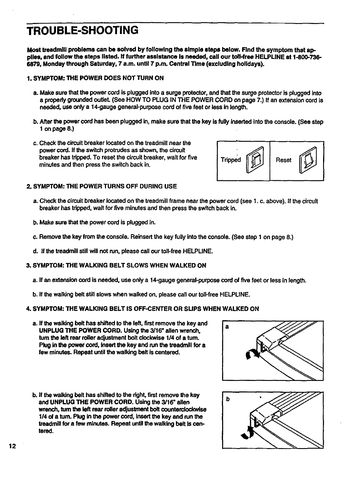
c. Check the circuit breaker located on the treadmill near the
power cord. If the switch protrudes as shown, the circuit
breaker has tripped. To reset the circuit breaker, wait for five
minutes and then press the switch back in. Tdpped Reset
2. SYMPTOM: THE POWER TURNS OFF DURING USE
a. Check the circuit breaker located on the treadmill frame near the power cord (see 1. c. above). If the circuit
breaker has tripped, wait for five minutes and then press the switch back in.
b. Make sure that the power cord is plugged in.
c. Remove the key from the console. Reiosert the key fully into the console. (See step I on page 8.)
d. If the treadmill still will not run, please call our toll-free HELPLINE.
3. SYMPTOM: THE WALKING BELT SLOWS WHEN WALKED ON
a. If an extension cord is needed, use only a 14-gauge general-purpose cord of five feet or less in length.
b. If the walking belt still slows when walked on, please call our toll-free HELPLINE.
4. SYMPTOM: THE WALKING BELT IS OFF-CENTER OR SLIPS WHEN WALKED ON
a. If the walking belt has shifted to the left, first remove the key and a
UNPLUG THE POWER CORD. Using the 3/16" allen wrench,
turn the left rear roller adjustment bolt clockwise 1/4 of a turn.
Plug in the power cord, insert the key and run the treadmill for a
few minutes. Repeat until the walking belt is centered.
12
b. If the walking belt has shifted to the dght, first remove the key
and UNPLUG THE POWER CORD. Using the 3/16" allen
wrench, turn the left rear roller adjustment bolt counterclockwise
1/4 of aturn. Plug in the power cord, Insert the key and run the
treadmill for a few minutes. Repeat unUIthe walking belt is can-
tered.
b
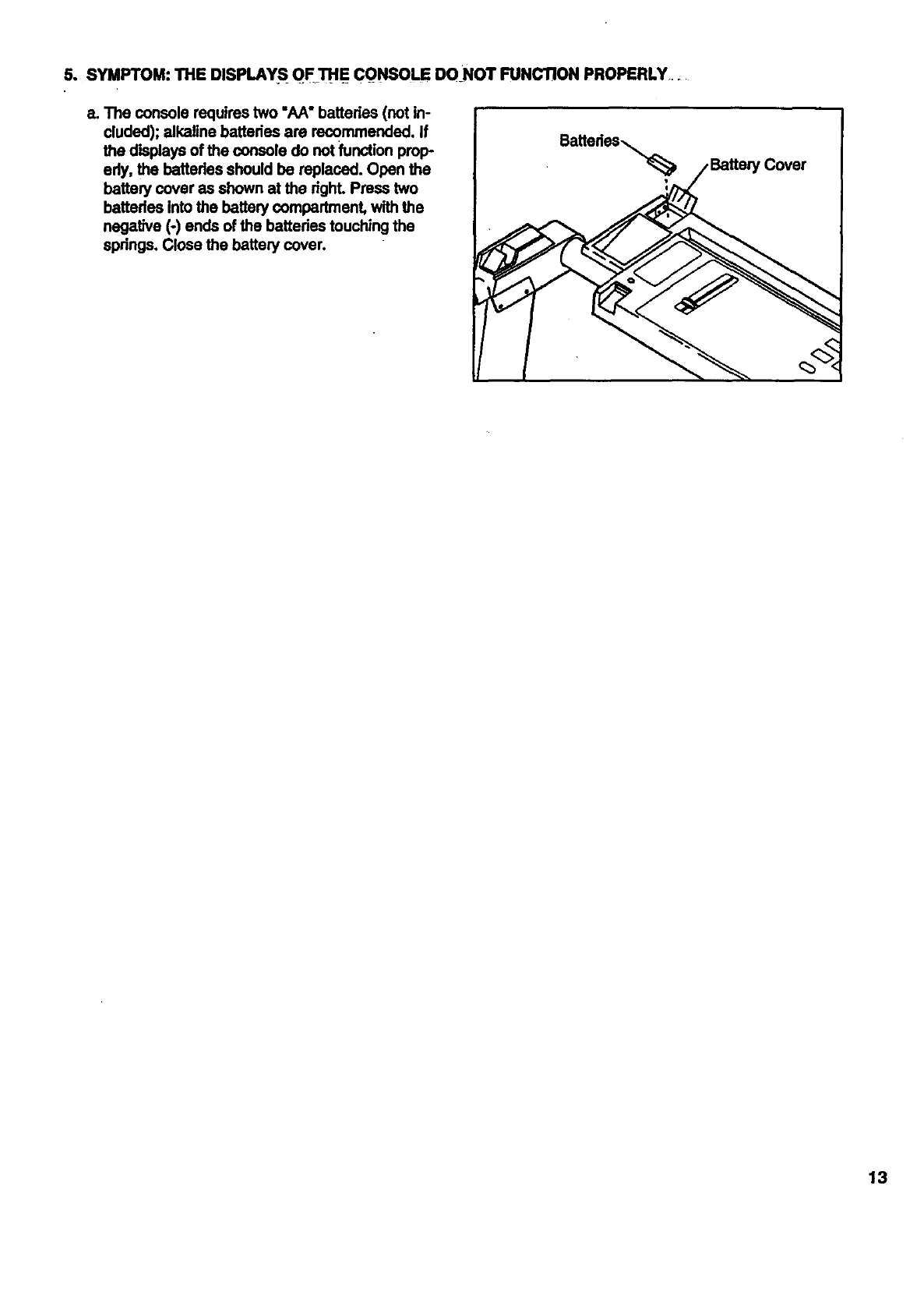
5. SYMPTOM:THEDISPLAYS OF_THECONSOLEDONOTFUNCTIONPROPERLY.
e.Theconsolerequirestwo"AA"batteries(notin-
cluded);alkalinebatteriesarerecommended.If
thedisplaysofthe console do not function prop-
edy, the batteries should be replaced. Open the
battery cover as shown at the dghL Press two
batteries into the battery compartment, with the
negative (-) ends of the bettedes touching the
springs. Close the battery cover.
eatterias_,...
13
CONDITIONING GUIDELINES
The following guidelines will help you to plan your ex-
ercise program. Remember--these are general guide-
fines. For more detailed information about exercise,
obtain areputable book or consult your physician.
EXERCISE INTENSITY
Fat Burning
To bum fat effectively, you must exercise at a relatively
low intensity level for a sustained period of time. During
the first few minutes of exercise, your body uses easily
accessibis carbohydrate calories for energy. Only after
the first few minutes does your body begin to use
stored fat calories for energy. If your goal is to bum fat,
adjust the speed and incline of the treadmill untilyour
heart rate is near the lowest number in your training
zone as you exercise. It may also be helpful to set the
speed control on the console to FAT BURN to help you
maintain the proper intensity level. (See page 8.)
Aerobic Exercise
Whether your goal is to bum fat or to strengthen your
cardiovascular system, the key to achieving the de-
sired results is to exercise with the proper intensity.
The proper intensity level can be found by usingyour
heart rate as a guide.
The chart below shows recommended heed rates for
fat buming, aerobic exercise, and high performance
athletic conditioning. (This chart is also found on the
console.)
If your goal is to strengthen your cardiovascular sys-
tem, your exercise must be "aerobic." Aerobic exercise
is activity that requires large amounts of oxygen for
prolonged periods of time. This increases the demand
on the heart to pump blood to the muscles, and on the
lungs to oxygenate the blood. For aerobic exercise,
adjust the speed and incline of the treadmill until your
heart rate is near the middle number in your training
zone. It may also be helpful to set the speed control on
the console to AEROBIC to help you maintain the
proper intensity level. (See page 8.)
14
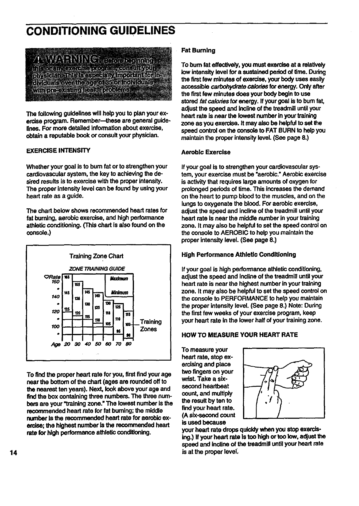
Training Zone Chart
ORate
160
120
100
ZONE TRAINING GUIDE
us I/.az_um
_ i fie 110 #6 _Training
Zones
To find the proper heart rate for you, first find your age
near the bottom of the chart (ages are rounded off to
the nearest ten years). Next, look above your age and
find the box containing three numbers. The three num-
bers are your "training zone." The lowest number is the
recommended heart rate for fat burning; the middle
number Is the recommended heart rate for aerobic ex-
erdse; the highest number is the recommended heert
rate for high performance athletic conditioning.
High Performance Athletic Conditioning
If your goal is high performance athletic conditioning,
adjust the speed and incline of the treadmill until your
heart rate is near the highest number in your training
zone. It may also be helpful to set the speed control on
the console to PERFORMANCE to help you maintain
the proper intensity level. (See page 8.) Note: During
the first few weeks of your exercise program, keep
your heart rate in the lower half of your training zone.
HOW TO MEASURE YOUR HEART RATE
To measure your
heart rate, stop ex-
ercislng and place
two fingers on your
wrist. Take a six-
second heartbeat
count, and multiply
the result by ten to
find your heart rate.
(A six-second count
is used because
your heart rate drops quickly when you stop exercis-
ing.) If your heart rate is too high or too tow, adjust the
speed and Incline of the treadmill until your heart rate
is at the proper level_
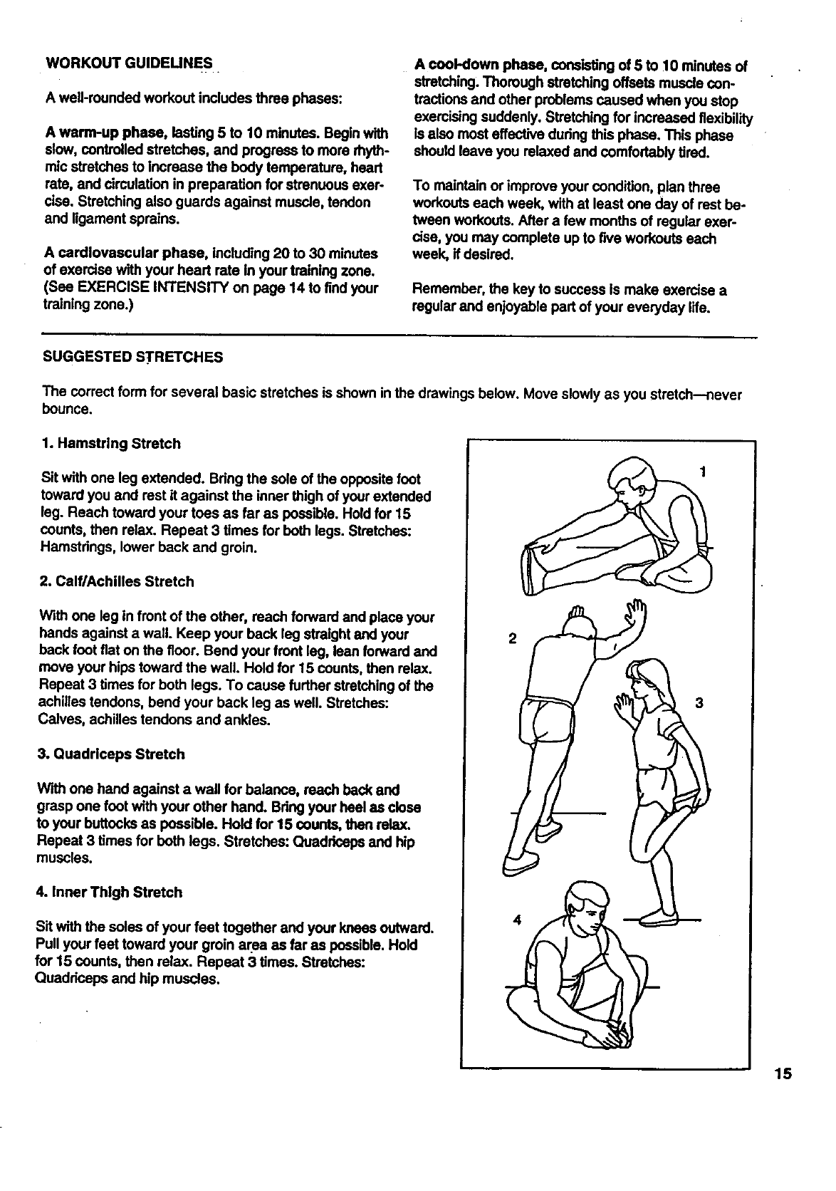
WORKOUTGUIDEUNES
Awell-roundedworkoutincludesthroephases:
A warm-upphase,lasting5 to 10minutes.Beginwith
slow,controlledstretches,and progress to more rhyth-
mic stretches to increase the body temperaturo, head
rate, and circulation in proparation for strenuous exer-
cise. Stretching also guards against muscle, tendon
and ligament sprains.
A cardiovascular phase, including 20 to 30 minutes
of exercise with your heart rate In your training zone.
(See EXERCISE INTENSITY on page 14 to find your
training zone.)
A cool-down phase, consisting of 5 to 10 minutes of
stretching, Thorough stretching offsets muscle con-
tractions and other problems caused when you stop
exercising suddenly. Stretching for increased flexibility
is also most effective during this phase. This phase
should leave you relaxed and comfortably tired.
To maintain or improve your condition, plan throe
workouts each week, with at least one day of rest be-
tween workouts. After a few months of regular exer-
cise, you may complete up to five workouts each
week, if desired.
Remember, the key to success is make exercise a
regular and enjoyable pad of your everyday life.
SUGGESTED STRETCHES
The correct form for several basic stretches is shown in the drawings below. Move slowly as you stretch--never
bounce.
1. Hamstring Stretch
Sit with one leg extended. Bring the sole of the opposite foot
toward you and rest it against the inner thigh of your extended
leg. Reach toward your tees as far as possible. Hold for 15
counts, then relax. Repeat 3 times for beth legs. Stretches:
Hamstrings, lower back and groin.
2. Calf/Achilles Stretch
With one leg in front of the other, roach forward and place your
hands against a wall. Keep your beck leg straight and your
back foot fiat on the floor. Bend your front leg, lean forward and
move your hips toward the wall. Hold for 15 counts, then relax.
Repeat 3 times for both legs. To cause further stretching of the
achilles tendons, bend your back leg as well. Stretches:
Calves, achilles tendons and ankles.
3. Quadriceps Stretch
With one hand against a wall for balance, reach back and
grasp one foot with your other hand. Bring your heel as close
to your buttocks as possible. Hold for 15 counts, then relax.
Repeat 3 times for both legs. Stretches: Quadriceps and hip
muscles.
4. Inner Thigh Stretch
Sit with the soles of your feet together and your knees outward.
Pull your feet toward your groin area as far as possible. Hold
for 15 counts, then relax. Repeat 3 times. Stretches:
Quadrieeps and hip muscles.
4
3
15

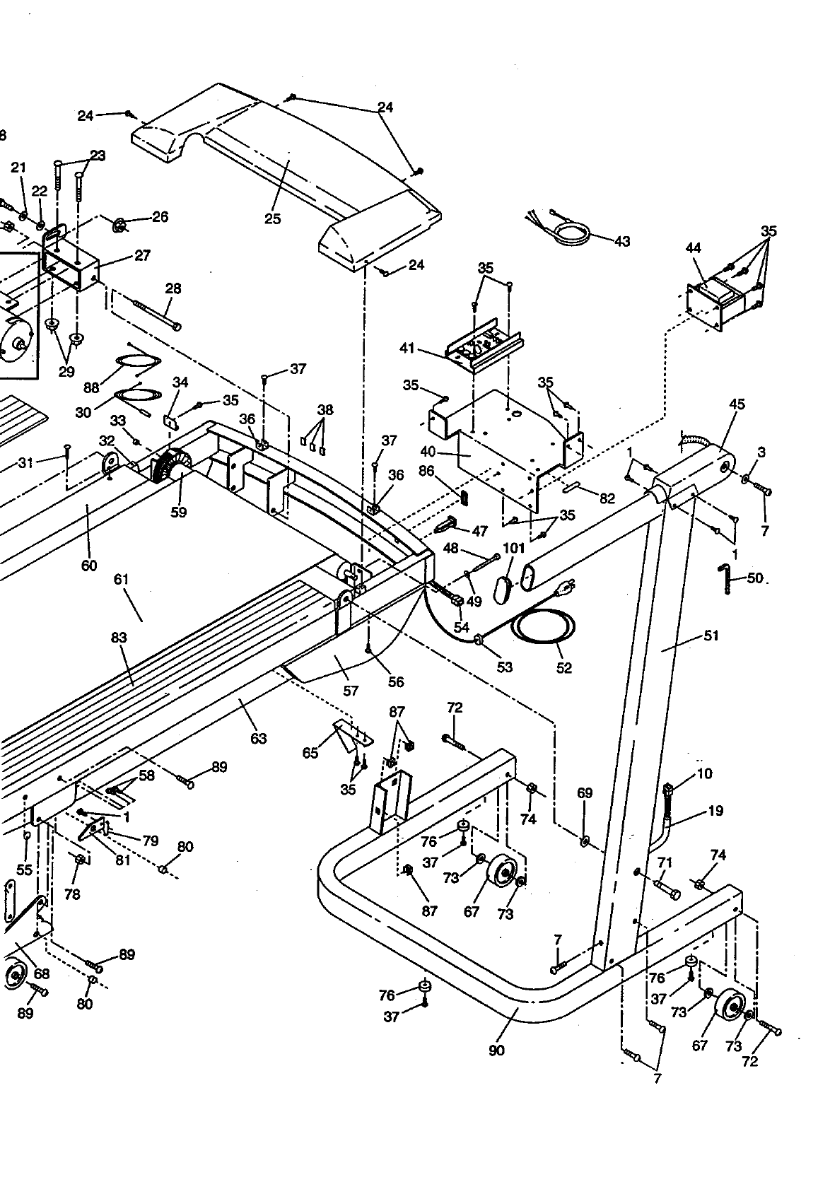
REMOVE THIS EXPLODED DRAWING
AND PART LIST FROM THE MANUAL
Save this EXPLODED DRAWING and PART LIST for future reference.
Note: Specifications are subject to change without notice. For information about
ordering replacement parts, see the back cover of the user's manual.
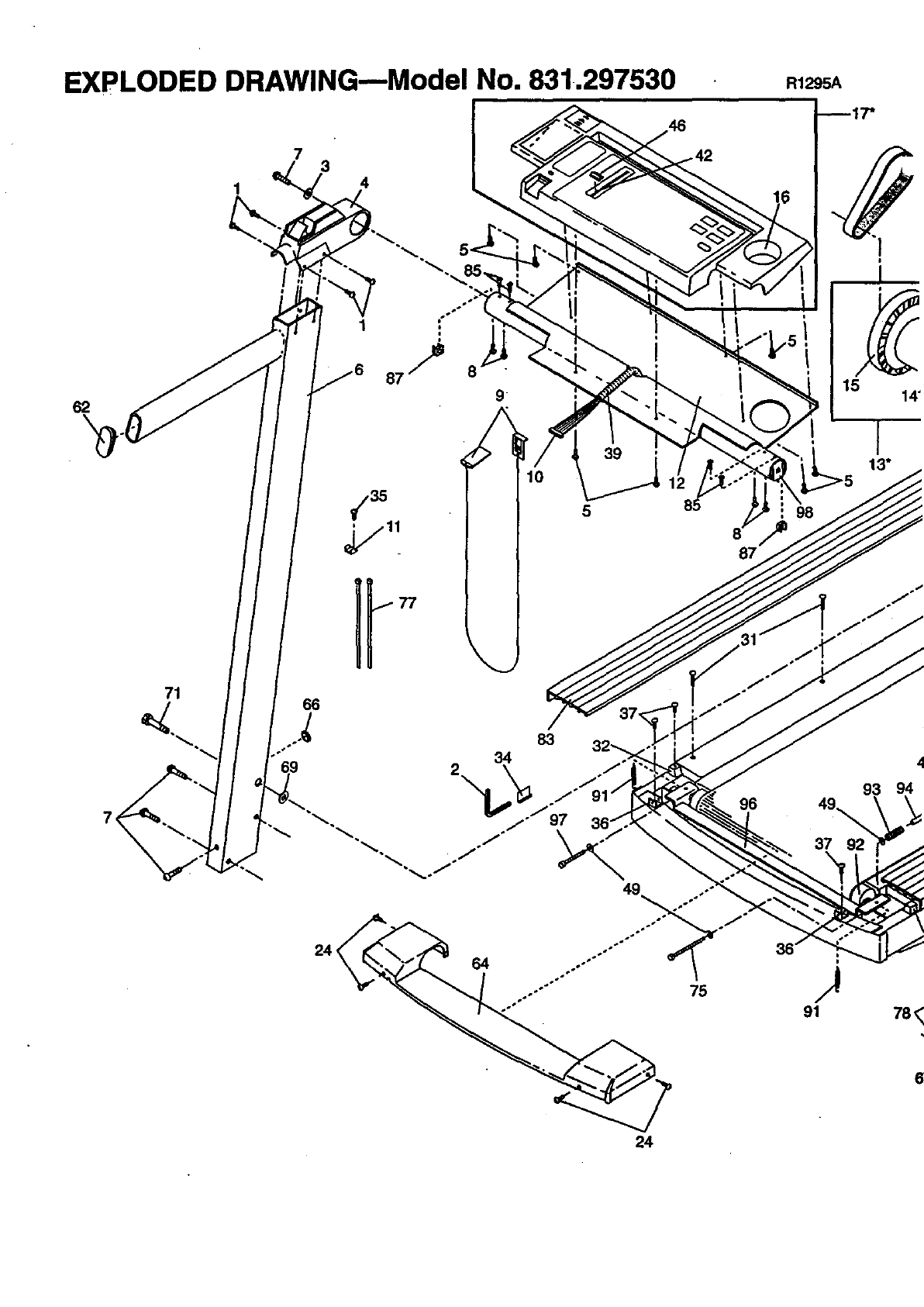
EXPLODED DRAWING--Model No. 831.297530
4
73
R1295A
_17"
62
71
69
1 '°°
J
87 _8
9
83
34
2
24
15 14"
o÷
45
6O 61
83
59
63
35
52
I
7
1
89
78
8O
•79 80
87 67 73
9O
7
74
67
i
I
72
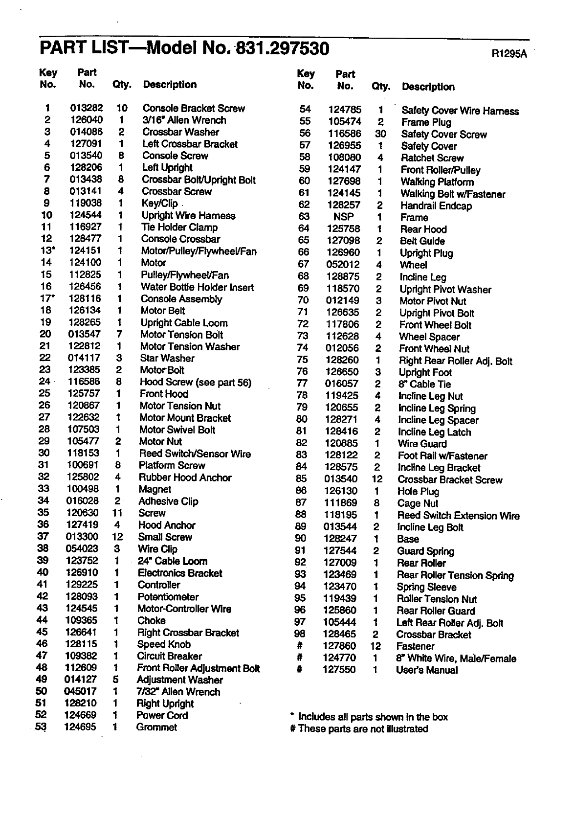
PART LIST-Model No, 831.297530
Key Part Key Part
No. No. Qty. Deacdption No. No. Qty, Deacription
R1295A
1 013282 10 Console Bracket Screw 54 124785 1 " Safety Cover Wire Hamess
2 126040 1 3/16* Allen Wrench 55 105474 2 Frame Plug
3 014086 2 Crossbar Washer 56 116586 30 Safety Cover Screw
4 127091 1 Left Crossbar Bracket 57 126955 1 Safety Cover
5 013540 8 Console Screw 58 108080 4 Ratchet Screw
6 128208 1 Left Upright 59 124147 1 Front Roller/Pulley
7 013438 8 Crossbar Bolt/Upright Bolt 60 127698 1 Walking Platform
8 013141 4 Crossbar Screw 61 124145 1 Walking Belt w/Fastener
9 119038 1 Key/Clip. 62 128257 2 Handrail Endcap
10 124544 1 Upright Wire Harness 63 NSP 1 Frame
11 116927 1 Tie Holder Clamp 64 125756 1 Rear Hood
12 128477 1 Console Crossbar 65 127098 2 Belt Guide
13" 124151 1 Motor/Pulley/Flywheel/Fan 86 126960 1 Upright Plug
14 124100 1 Motor 67 052012 4 Wheel
15 112825 1 Pulley/Flywheal/Fan 68 128875 2 Incline Leg
16 126456 1 Water Bottle Holder Insert 69 118570 2 Upright Pivot Washer
17" 128116 1 Console Assembly 70 012149 3 Motor Pivot Nut
18 126134 1 Motor Belt 71 126635 2 Upright Pivot Bolt
19 128265 1 Upright Cable Loom 72 117806 2 Front Wheel Bolt
20 013547 7 Motor Tension Bolt 73 112628 4 Wheel Spacer
21 122812 1 Motor Tension Washer 74 012056 2 Front Wheel Nut
22 014117 3 Star Washer 75 128260 1 Right Rear Roller Adj. Bolt
23 123385 2 Motor Bolt 76 126650 3 Upright Foot
24 - 116586 8 Hood Screw (see part 56) 77 016057 2 8" Cable Tie
25 125757 1 Front Hood 78 119425 4 Incline Leg Nut
26 120867 1 Motor Tension Nut 79 120655 2 Incline Leg Spdng
27 122632 1 Motor Mount Bracket 80 128271 4 Incline Leg Spacer
28 107503 1 Motor Swivel Bolt 81 128416 2 Incline Leg Latch
29 105477 2 Motor NUt 82 120865 1 Wire Guard
30 118153 1 Reed Switch/Sensor Wire 83 128122 2 Foot Rail w/Fastener
31 100691 8 Platform Screw 84 126575 2Incline Leg Bracket
32 125802 4 Rubber Hood Anchor 85 013540 12 Crossbar Bracket Screw
33 100498 1 Magnet 86 126130 1 Hole Plug
34 016028 2 • Adhesive Clip 87 111869 8 Cage Nut
35 120630 11 Screw 88 118195 1 Reed Switch Extension Wire
35 127419 4 Hood Anchor 89 013544 2 incline Leg Belt
37 013300 12 Small Screw 90 128247 1 Base
38 054023 3 Wire Clip 91 127544 2 Guard Spring
39 123752 1 24" Cable Loom 92 127009 1 Rear Roller
40 126910 1 Electronics Bracket 93 123469 1 Rear Roller Tansion Spring
41 129225 1 Controller 94 123470 1 Spring Sleeve
42 128093 1 Potentiometer 95 119439 1 Roller Tension NUt
43 124545 1 Motor-Controllar Wire 96 125860 1 Rear Roller Guard
44 109365 1 Choke 97 105444 1 Left Rear Roller Adj. Bolt
45 126641 1 Right Crossbar Bracket 98 128465 2 Crossbar Bracket
46 128115 1 Speed Knob #127860 12 Fastener
47 109382 1 Cimuit Breaker # 124770 1 8" White Wire, Male/Female
48 112609 1 Front Rollor A_justment Bolt # 127550 1 User's Manual
49 014127 5 Adjustment Washer
50 045017 1 7/32" Allen Wrench
51 128210 1 Right Upright
52 124669 1 Power Cord * Includes all parts shown in the box
• 53.. 124095 1 Grommet # These parts are not illustrated

ModelNo.831_37530
QUESTIONS?
If you find that:
• you need help assembling or
operating the SPACE MAKER
1000 LS treadmill
• a part is missing
• or you need to schedule repair
service
call our toll-free HELPLINE
1-800-736-6879
Monday-Saturday, 7 am-7 pm
Central Time (excluding holidays)
REPLACEMENT
PARTS
if parts become worn and need
to be replaced, call the following
toll-free number
1-800-FON-PART
(1-800-366-7278)
"l'hemodel number and ssdal number of your SEARS_ SPACE
MAKER 1000 LS trssdmill are listed on adecal attached to the
frame. See the front cover of this manual to find the location of the
decal.
All replacement parts are available for immediate purchase or
special order when you visit your nearest SEARS Service Canter.
To request service or to order parts by telephone, cell the toll-free
numbers listed at the left.
When requesting help or service, or ordedng pads, please be pre-
pared to provide the following information:
•The NAME OFTHE PRODUCT (SEARS®.SPACE MAKER 1000
LS treadmill)
•The MODEL NUMBER OF THE PRODUCT (831.297530)
• The PART NUMBER OF THE PART (see the EXPLODED
DRAWING and PART LIST attached to the center of this manual)
•The DESCRIPTION OFTHE PART (see the EXPLODED DRAW-
ING and PART LIST attached to the canter of this manual)
SEARS, ROEBUCK AND CO. HOFFMAN ESTATES, IL 60179 USA
'Part No. 127550 EO3567AC R1295A Printed in USA ©1995 Sears, Roebuck and Co.
