Liftmaster 8550 Users Manual 114A4243
2014-12-11
: Liftmaster Liftmaster-8550-Users-Manual-120538 liftmaster-8550-users-manual-120538 liftmaster pdf
Open the PDF directly: View PDF ![]() .
.
Page Count: 40
- English
- Owner's Manual
- Preparation
- Assembly
- Installation
- Determine the header bracket location
- Install the Header Bracket
- Attach the rail to the header bracket
- Position the garage door opener
- Hang the garage door opener
- Install the light bulbs
- Attach the emergency release rope and handle
- Install the door bracket
- Connect the door arm to the trolley
- Install the Door Control
- Install the Protector System®
- Power
- Adjustments
- Battery Backup
- Operation
- Features
- Door Control
- Remote Controls
- To Open the Door Manually
- Maintenance
- Troubleshooting
- Repair Parts
- Contact Information
- Accessories
- Warranty
- Spanish
Serial Number:
Date of Purchase:
Belt Drive Garage Door Opener
The Chamberlain Group, Inc.
845 Larch Avenue
Elmhurst, Illinois 60126-1196
www.liftmaster.com
.
Write down the following information
for future reference:
NOTE: If you are installing the garage door opener on a one-piece door, visit
www.liftmaster.com for installation instructions.
Contents
Model 8550
FOR RESIDENTIAL USE ONLY
BELT DRIVE GARAGE DOOR OPENER .. 1
PREPARATION ............................. 2
ASSEMBLY ................................. 4
INSTALLATION ........................ 6-13
INSTALL THE DOOR CONTROL .....14-16
INSTALL THE
PROTECTOR SYSTEM® ..............17-20
POWER ................................21-22
ADJUSTMENT.........................23-25
BATTERY BACKUP ...................26-27
OPERATION ...............................28
FEATURES.................................29
DOOR CONTROL .....................30-31
REMOTE CONTROLS .................32-33
TO ERASE THE MEMORY ...............33
TO OPEN THE DOOR MANUALLY ......34
MAINTENANCE ...........................34
TROUBLESHOOTING ................. 35-36
REPAIR PARTS .......................37-38
ACCESSORIES ............................39
WARRANTY ...............................40
■ Please read this manual and the enclosed safety materials carefully!
■ Fasten the manual near the garage door after installation.
■ The door WILL NOT CLOSE unless the Protector System® is connected and properly
aligned.
■ Periodic checks of the garage door opener are required to ensure safe operation.
■ The model number label is located on the left side panel of your garage door opener.
■ This garage door opener is ONLY compatible with MyQ™ and Security✚®2.0
accessories.
■ DO NOT enable the Timer-To-Close feature if you are installing the garage door
opener on a one-piece door. The Timer -To-Close is to be used ONLY with
sectional doors.
2
Safety Symbol and Signal
Word Review
This garage door opener has been designed and
tested to offer safe service provided it is installed,
operated, maintained and tested in strict
accordance with the instructions and warnings
contained in this manual.
When you see these Safety Symbols and Signal
Words on the following pages, they will alert you
to the possibility of serious injury or death if you
do not comply with the warnings that accompany
them. The hazard may come from something
mechanical or from electric shock. Read the
warnings carefully.
Mechanical
Electrical
When you see this Signal Word on the following
pages, it will alert you to the possibility of damage
to your garage door and/or the garage door
opener if you do not comply with the cautionary
statements that accompany it. Read them
carefully.
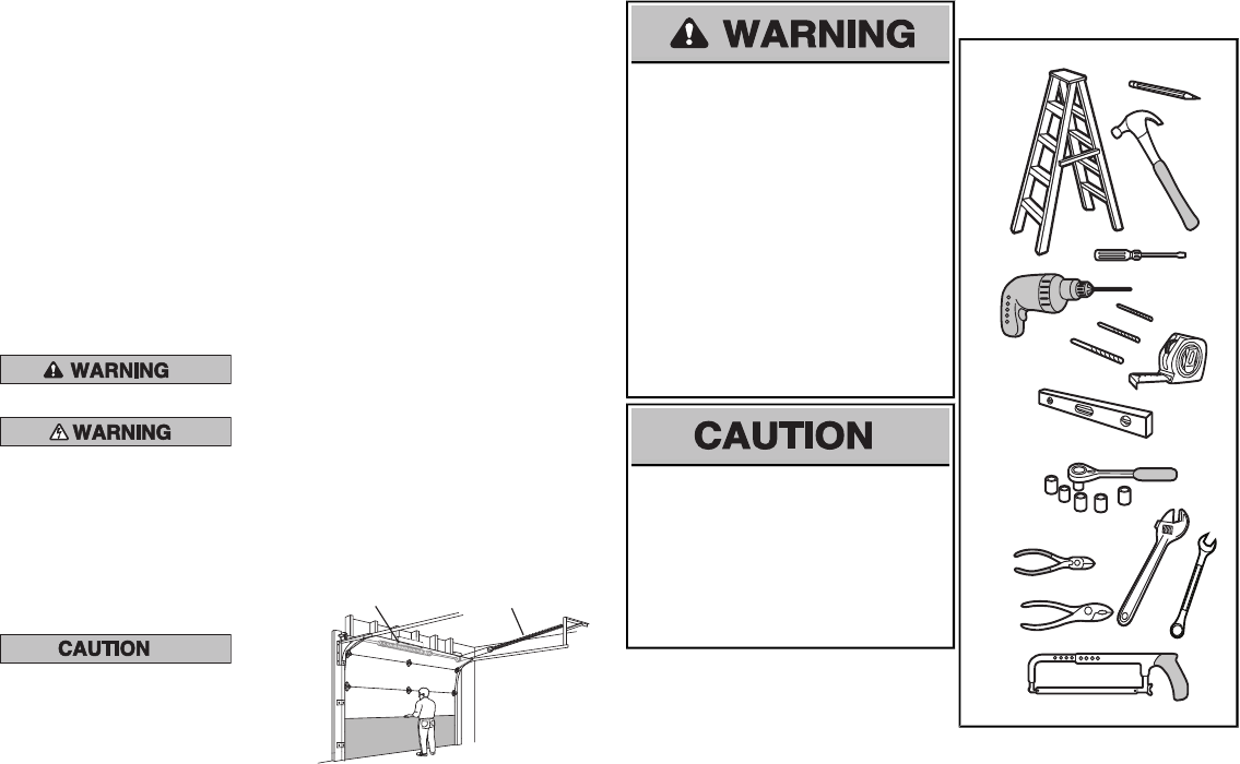
Check the Door
1. Disable locks and remove any ropes
connected to the garage door.
2. Lift the door halfway up. Release the
door. If balanced, it should stay in
place, supported entirely by its springs.
3. Raise and lower the door to check for
binding or sticking. If your door binds,
sticks, or is out of balance, call a trained
door systems technician.
4. Check the seal on the bottom of the
door. Any gap between the floor and
the bottom of the door must not exceed
1/4 inch (6 mm). Otherwise, the safety
reversal system may not work properly.
5. The opener should be installed above
the center of the door. If there is a
torsion spring or center bearing plate
in the way of the header bracket, it may
be installed within 4 feet (1.2 m) to the
left or right of the door center. See
installing the Header Bracket section.
Torsion Spring Extension Spring
To prevent possible SERIOUSINJURYor
DEATH:
• ALWAYS call a trained door systems
technician if garage door binds, sticks, or is
out of balance. An unbalanced garage
door may not reverse when required.
• NEVER try to loosen, move or adjust
garage door, door springs, cables, pulleys,
brackets or their hardware, ALLof which
are under EXTREMEtension.
• Disable ALLlocks and remove ALLropes
connected to garage door BEFORE
installation and operating garage door
opener to avoid entanglement.
To prevent damage to garage door and
opener:
• ALWAYS disable locks BEFORE installing
and operating the opener.
• ONLY operate garage door opener at
120 V, 60 Hz to avoid malfunction and
damage.
Tools Needed
2
1
3/16
7/16
1/2
5/32
5/16
5/8
9/16
1/4
7/16
Preparation
3
AB
C
J
N
I
O
DE
F
H
GK
L
M
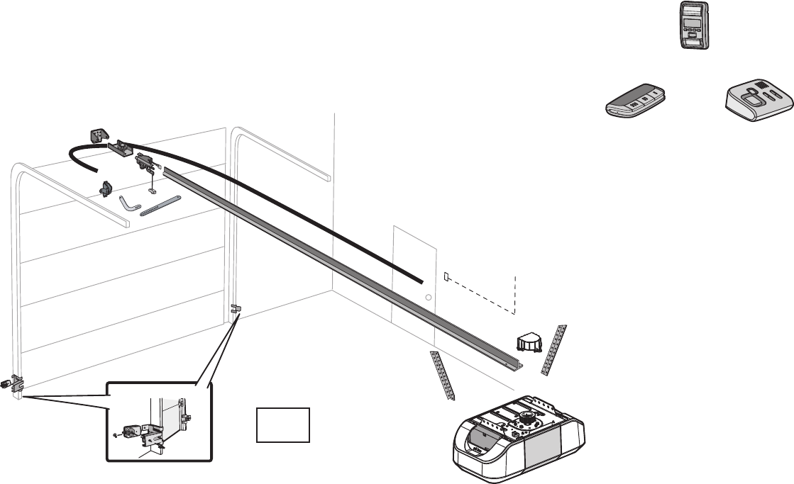
Overview/Carton Inventory
GARAGE DOOR OPENER ASSEMBLY
A.tekcarb redaeH
B. Pulley and bracket
C.tekcarb rooD
D.mra rood devruC
E.mra rood thgiartS
F.yellorT
G. Emergency release rope and handle
H. Rail
I.renepo rood egaraG
NOTE: Accessories will vary depending on the garage door opener model purchased. Depending on your specific model, other accessories
may be included with your garage door opener. The instructions for these accessories will be attached to the accessory and are not included
in this manual. The images throughout this manuals are for reference and your product may look different.
J. swercs dna revoc tekcorpS
K.tleB
L.lortnoc rooD
M. eriw etihw/der dna etihW
The Protector System®
N.srosnes gnisrever ytefaS
with white and white/black wire attached:
Sending Sensor (1) Receiving Sensor (1)
and Safety Sensor Brackets (2)
O.erutaretil dna slebal ytefaS
Hardware
Assembly
H1 Hex Screw #8x3/8" (3)
[packed with the sprocket cover]
Installation
H2 Hex Bolt 5/16"-18 x 7/8" (4)
H3 Lag Screw 5/16"-9 x 1-5/8" (2)
H4 Lag Screw 5/16"-18 x 1-5/8" (2)
H5 Clevis Pin 5/16" x 2-3/4" (1)
H6 Clevis Pin 5/16" x 1-1/4" (1)
H7 Clevis Pin 5/16" x 1" (1)
H8 Nut 5/16"-18 (4)
H9 Lock Washer 5/16"-16 (4)
H10 Self-Threading Screw 1/4"-14 x 5/8" (2)
H11 Ring Fastener (3)
H12 Carriage Bolt 1/4"-20 x 1/2" (2)
H13 Wing Nut 1/4"-20 (2)
Door Control Hardware
H14 Screw 6AB x 1-1/4" (2)
H15 Screw 6-32 x 1" (2)
H16 Drywall Anchors (2)
H17 Insulated Staples (10)
895MAX
Remote Control
880LM
Smart Control
Panel®829LM
Garage Door
Monitor
MyQ™ AND SECURITY✚®2.0
ACCESSORIES
4
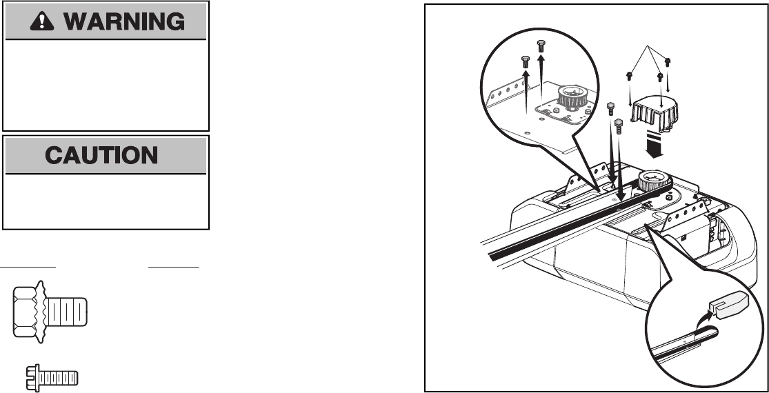
To avoid possible SERIOUS INJURY to finger
from moving garage door opener:
• ALWAYS keep hand clear of sprocket while
operating opener.
• Securely attach sprocket cover BEFORE
operating.
To avoid SERIOUS damage to garage door
opener, use ONLY those bolts/fasteners
mounted in the top of the opener.
.
Mounted in the
garage door opener
HARDWARE
H1 (3)
Hex Screw
#8x3/8"
(Packed with the
sprocket cover)
NOTE: ONLY use the bolts removed from the
garage door opener.Place the garage door
opener on the packing material to prevent
scratching.
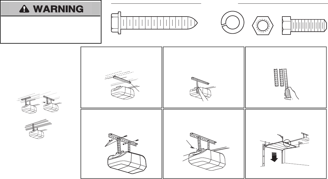
1.1 Remove the two bolts from the top of the
garage door opener.
1.2 Align the rail and the styrofoam over the
sprocket. Cut the tape from the rail, belt,
and styrofoam.
1.3 Fasten the rail with the previously removed
bolts.
1.4 Position the belt around the garage door
opener sprocket.
1.5 Attach the sprocket cover over the garage
door opener sprocket and attach with hex
screws (H1).
H1
Assembly
1Attach the rail to the garage door opener
5
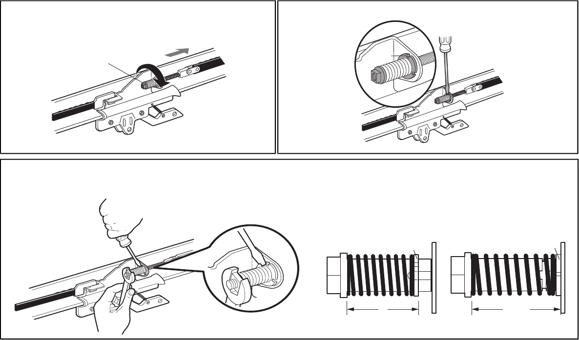
2Tighten the Belt
2.1 By hand, thread the spring trolley nut on the threaded shaft until it is finger tight against
the trolley. Do not use any tools.
Spring Trolley Nut
(To motor unit)
2.2 Insert a flathead screwdriver tip into one of the nut ring slots and brace it firmly against the trolley.
Nut ring
slot
2.3 Tighten the spring trolley nut with an adjustable wrench or a 7/16” open end wrench about a quarter turn until the spring releases and snaps the nut ring against the trolley. This sets the spring to
optimum belt tension.
Nut Ring Nut Ring
AFTER RELEASE
1-1/4"
(3.18 cm)
BEFORE
1"
(2.5 cm)

6
IMPORTANT INSTALLATION INSTRUCTIONS
WARNING
To reduce the risk of SEVERE INJURY or DEATH:
1. READ AND FOLLOW ALL INSTALLATION WARNINGS AND INSTRUCTIONS.
2. Install garage door opener only on properlybalanced and lubricated garage door. An
improperly balanced door may not reverse when required and could result in SEVERE
INJURY or DEATH.
3. ALL repairs to cables, spring assemblies and other hardware MUST be made by a trained
door systems technician BEFORE installing opener.
4. Disable ALL locks and remove ALL ropes connected to garage door BEFORE installing
opener to avoid entanglement.
5. Install garage door opener 7 feet (2.13 m) or more above floor.
6. Mount the emergency release within reach, but at least6 feet (1.83 m) above the floor and
avoiding contact with vehicles to avoid accidental release.
7. NEVER connect garage door opener to power source until instructed to do so
8. NEVERwear watches, rings or loose clothing while installing or servicing opener. They could
be caught in garage door or opener mechanisms.
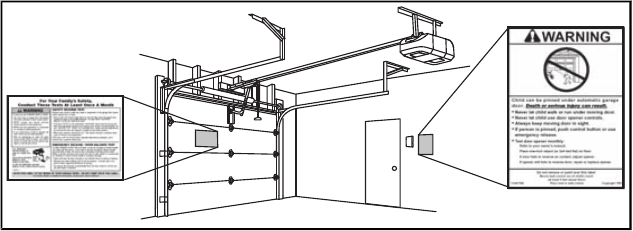
9. Install wall-mounted garage door control:
• within sight of the garage door.
• out of reach of children at minimum height of 5 feet (1.5 m).
• away from ALL moving parts of the door.
10. Place entrapment warning label on wall next to garage door control
11. Place manual release/safety reverse test label in plain view on inside of garage door.
12. Upon completion of installation, test safety reversal system. Door MUST reverse on.contact with
a 1-1/2" (3.8 cm) high object (or a 2x4 laid fl at) on the floor.
13. To avoid SERIOUS PERSONAL INJURY or DEATH from electrocution, disconnectALL
electric and battery power BEFORE performing any service or maintenance.
14. DO NOT enable the Timer-to-Close functionality if operating either one-piece or swinging
garage doors. To be enabled ONLY when operating a sectional door.
NOTE:If you are installing the garage door opener on a one-piece door, visit www.liftmaster.com for installation instructions.
Installation
7
To prevent possible SERIOUS INJURY or
DEATH:
• Header bracket MUST be RIGIDLY
fastened to structural support on header
wall or ceiling, otherwise garage door might
NOT reverse when required. DO NOT
install header bracket over drywall.
• Concrete anchors MUST be used if
mounting header bracket or 2x4 into
masonry.
• NEVER try to loosen, move or adjust
garage door, springs, cables, pulleys,
brackets, or their hardware, ALL of which
are under EXTREME tension.
• ALWAYS call a trained door systems
technician if garage door binds, sticks, or is
out of balance. An unbalanced garage
door might NOT reverse when required.
• DO NOT enable the Timer-to-Close
functionality if operating either one-piece or
swinging garage doors. To be enabled
ONLY when operating a sectional door.
1Determine the header bracket location
NOTE: If you are installing the garage door opener on a one-piece door, visit www.liftmaster.com for
installation instructions.
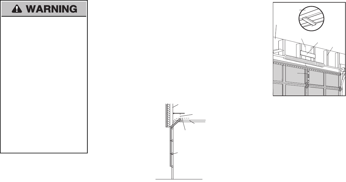
1.1 Close the door and mark the inside vertical centerline of the garage door.
1.2 Extend the line onto the header wall above the door.
You can fasten the header bracket within 4 feet (1.22 m) of the left or right of the door
center only if a torsion spring or center bearing plate is in the way; or you can attach it to
the ceiling when clearance is minimal. (It may be mounted on the wall upside down if
necessary, to gain approximately 1/2" (1 cm).
If you need to install the header bracket on a 2x4 (on wall or ceiling), use lag screws (not
provided) to securely fasten the 2x4 to structural supports.
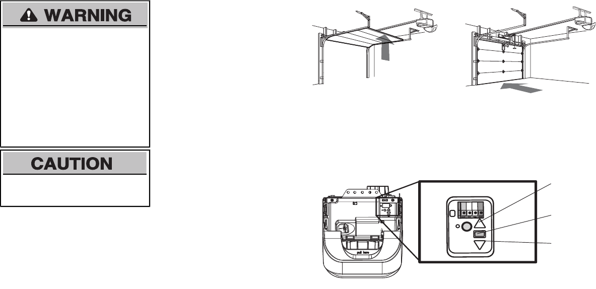
1.3 Open your door to the highest point of travel as shown. Draw an intersecting horizontal line on
the header wall 2" (5 cm) above the high point. This height will provide travel clearance for the
top edge of the door.
NOTE: If the total number of inches exceeds the height available in your garage, use the maximum
height possible, or refer to page 8 ceiling installation.
Sectional door with curved track
Header Wall
Track
2" (5 cm)
Highest Point
of Travel
Door
Header Wall
Unfinished Ceiling
Vertical Centerline
of Garage Door 2x4
2x4
Structural
Supports
Level
(Optional)
OPTIONAL
CEILING
MOUNT FOR
HEADER
BRACKET
8
You can attach the header bracket either to the
wall above the garage door, or to the ceiling.
Follow the instructions which will work best for
your particular requirements. Do not install the
header bracket over drywall. If installing into
masonry, use concrete anchors (not provided).
HARDWARE
H3 (2)
Lag Screw
5/16"-9x1-5/8"
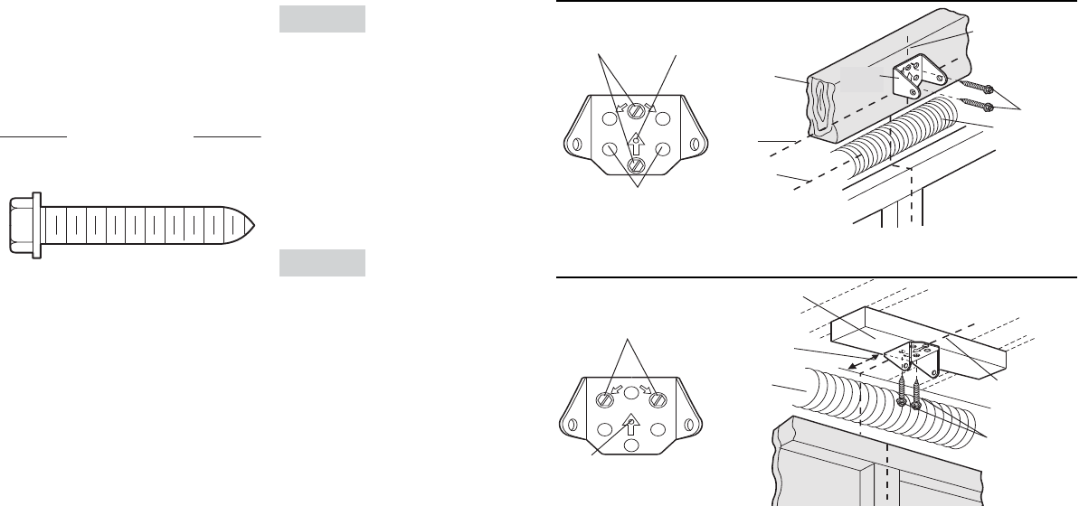
OPTION A WALL INSTALLATION
2.1A Center the bracket on the vertical
centerline with the bottom edge of the
bracket on the horizontal line as shown
(with the arrow pointing toward the
ceiling).
2.2A Mark the vertical set of bracket holes (do
not use the holes designated for ceiling
mount). Drill 3/16" pilot holes and fasten
the bracket securely to a structural
support with the hardware provided (H3).
OPTION B CEILING INSTALLATION
2.1B Extend the vertical centerline onto the
ceiling as shown.
2.2B Center the bracket on the vertical mark,
no more than 6" (15 cm) from the wall.
Make sure the arrow is pointing away
from the wall. The bracket can be
mounted flush against the ceiling when
clearance is minimal.
2.3B Mark the side holes. Drill 3/16" pilot holes
and fasten bracket securely to a structural
support with the hardware provided (H3).
UP
CEILING MOUNT ONLY
Wall Mount
Optional
Mounting
Holes
H3
Vertical
Centerline of
Garage Door
(Header Wall)
Header
Bracket
2x4 Structural
Support
Door Spring
(Garage Door)
Highest Point of
Garage Door
Travel
Horizontal
Line
The nail hole is for positioning
swercs gal esu tsum uoY .ylno
.tekcarb redaeh eht tnuom ot
UP
CEILING MOUNT ONLY
(Header Wall)
Ceiling Mounting Holes
(Finished Ceiling)
Vertical
Centerline of
Garage Door
Header
Bracket
6" (15 cm)
Maximum
Door Spring
(Garage Door)
H3
The nail hole is for positioning
swercs gal esu tsum uoY .ylno
.tekcarb redaeh eht tnuom ot
Installation
2 Install the Header Bracket
9
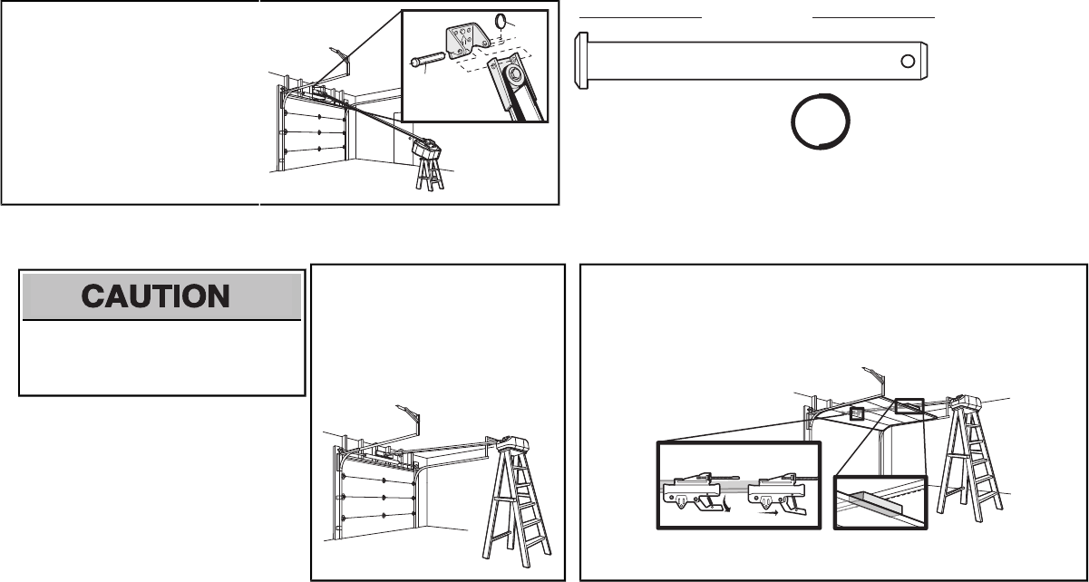
3.1 Align the rail with the header bracket.
Insert the clevis pin (H5) through the
holes in the header bracket and rail.
Secure with the ring fastener (H11).
NOTE: Use the packing material as a
protective base for the garage door opener.
H11
H5
HARDWARE
H5
Clevis Pin
5/16"x2-3/4"
H11
Ring Fastener
4Position the garage door opener
To prevent damage to garage door, rest garage
door opener rail on 2x4 placed on top section of
door.
4.1 Remove the packing material and lift the
garage door opener onto a ladder.
NOTE: A 2x4 is ideal for setting the distance
between the rail and the door. If the ladder is
not tall enough you will need help at this point.
4.2 Fully open the door and place a 2x4 (laid flat) under the rail.
NOTE: If the door hits the trolley when it is raised, pull the trolley release arm down to
disconnect the inner and outer trolley. Slide the outer trolley toward the garage door opener.
The trolley can remain disconnected until instructed.
Connected Disconnected
3Attach the rail to the header bracket
10
To avoid possible SERIOUS INJURY from a
falling garage door opener, fasten it SECURELY to
structural supports of the garage. Concrete anchors MUST
be used if installing ANY brackets into masonry.
HARDWARE
H4 (2)
Lag Screw 5/16"- 18x1-5/8" H2 (2)
Hex Bolt 5/16"- 18x7/8"
H8 (2)
Nut 5/16"-18
H9 (2)
Lock Washer
5/16"-16
Hanging the garage door opener will vary
depending on your garage. Below are three
example installations. Your installation may be
different. For ALL installations the garage door
opener MUST be connected to structural
supports. The instructions illustrate one of the
examples below.
Finished Ceiling
Unfinished Ceiling
5.1 On finished ceilings, use the lag screws
(H3) to attach a support bracket (not
provided) to the structural supports
before installing the garage door opener.
Finished
Ceiling
H4
(not provided)
H4
5.2 Make sure the garage door opener is
aligned with the header bracket. Measure
the distance from each side of the garage
door opener to the support bracket.
5.3 Cut both pieces of the hanging bracket to
required lengths.
5.4 Attach the end of each hanging bracket to
the support bracket with appropriate
hardware (not provided).
(not provided)
5.5 Attach the garage door opener to the
hanging brackets with the bolts (H2), lock
washers (H9) and nuts (H8).
H2
H8
H9
5.6 Remove the 2x4 and manually close the
door. If the door hits the rail, raise the
header bracket.
Installation
5Hang the garage door opener

11
To prevent possible OVERHEATING of the end panel or light socket:
• Use ONLY A19 incandescent or compact fluorescent light bulbs.
• DO NOT use incandescent bulbs larger than 100W.
• DO NOT use compact fluorescent light bulbs larger than 26W (100W) equivalent.
• DO NOT use halogen bulbs.
• DO NOT use short neck or specialty light bulbs.
6.1 Pull on the top center of the light lens and
rotate the light lens down.
6.2 Insert an A19 incandescent or compact
fluorescent light bulb (100 watt maximum),
into the light socket.
6.3 Rotate the lens up to close.
NOTE: The use of short neck or speciality light
bulbs may overheat the end panel or light socket.
or or
7Attach the emergency release rope and handle
To prevent possible SERIOUS INJURY or DEATH from a falling garage door:
• If possible, use emergency release handle to disengage trolley ONLY when garage door is
CLOSED. Weak or broken springs or unbalanced door could result in an open door falling
rapidly and/or unexpectedly.
• NEVER use emergency release handle unless garage doorway is clear of persons and
obstructions.
• NEVER use handle to pull door open or closed. If rope knot becomes untied, you could fall.
7.1 Insert one end of the emergency release
rope through the handle. Make sure that
“NOTICE” is right side up. Tie a knot at
least 1 inch (2.5 cm) from the end of the
emergency release rope.
7.2 Insert the other end of the emergency
release rope through the hole in the
trolley release arm.Make sure the
handle is 6 feet (1.83 m) above the floor
and secure with a knot.
Trolley
Release Arm
NOTE: If it is necessary to cut the emergency release rope, seal the cut end with a match or lighter to prevent unraveling. Ensure the emergency release
rope and handle are above the top of all vehicles to avoid entanglement.
6Install the light bulbs
12
Fiberglass, aluminum or lightweight steel garage doors WILLREQUIRE reinforcement BEFORE
installation of door bracket. Contactyour door manufacturer for reinforcement kit.
Figure 1 shows one piece of angle iron as the horizontal
brace. For the vertical brace, 2 pieces of angle iron are
used to create a U-shaped support. The bestsolution is to
check with your garage door manufacturer for an opener
installation door reinforcement kit.
NOTE: Many door reinforcement kits provide for direct
attachment of the clevis pin and door arm. In this case you
will not need the door bracket;proceed to the next step.
H10 (2)
Self-Threading Screw
1/4˝-14x5/8˝
HARDWARE
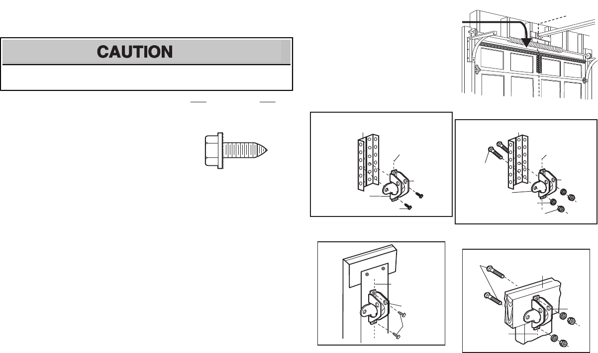
8.1 Center the door bracket on the previously marked vertical centerline used for the header bracket
installation. Note correct UP placement, as stamped inside the bracket.
8.2 Position the top edge of the bracket 2"-4" (5-10 cm) below the top edge of the door, OR directly below
any structural support across the top of the door.
8.3 Mark, drill holes and install as follows, depending on your door’s construction:
Metal or light weight doors using a vertical angle iron brace between the door panel support and
the door bracket:
• Drill 3/16" fastening holes. Secure the door bracket using the two self threading screws (H10).
(Figure 2)
• Alternately, use two 5/16" bolts, lock washers and nuts (not provided). (Figure 3)
Metal, insulated or light weight factory reinforced doors:
• Drill 3/16" fastening holes. Secure the door bracket using the self-threading screws (H10).
(Figure 4)
Wood Doors:
• Use top and bottom or side to side door bracket holes. Drill 5/16” holes through the door and
secure bracket with 5/16"x2" carriage bolts, lock washers and nuts (not provided). (Figure 5)
NOTE: The 1/4"-14x5/8" self-threading screws are not intended for use on wood doors.
8Install the door bracket
A horizontal and vertical reinforcement is
needed for lightweight garage doors
(fiberglass, aluminum, steel, doors with glass
panel, etc.) (not provided).
A horizontal reinforcement brace should be
long enough to be secured to two or three
vertical supports. A vertical reinforcement
brace should cover the height of the top panel.
Door
Bracket
Vertical
Centerline
of Garage Door
UP
Vertical
Reinforcement
FIGURE 2
H10
UP
H10
Vertical
Centerline
of Garage
Door
FIGURE 4
FIGURE 1
Door
Bracket
Nut
5/16"-18
Bolt
5/16"-18x2"
(Not Provided)
Lock Washer
5/16"
UP
Vertical Reinforcement
FIGURE 3
Vertical
Centerline
of Garage Door
UP
Inside Edge
of Door or
Reinforcement Board
Bolt 5/16"x2"
(Not Provided)
FIGURE 5
Vertical
Centerline
of Garage
Door
Installation
13
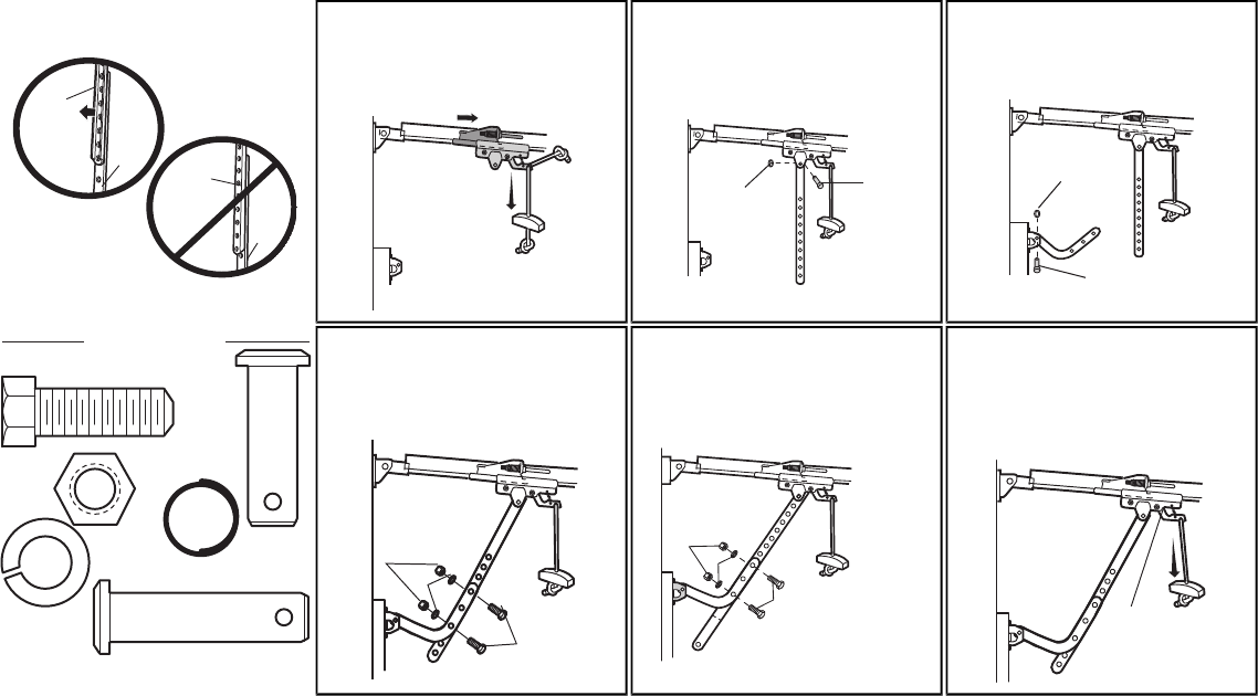
IMPORTANT: The groove on the straight door arm MUST face away from the curved door arm.
Straight
Door Arm Curved
Door
Arm
(Groove
facing out)
CORRECT
INCORRECT
Straight
Door
Arm Curved
Door
Arm
9.1 Close the door. Disconnect the trolley by
pulling the emergency release handle.
Slide the outer trolley back (away from
the door) about 2" (5 cm).
9.2 Attach the straight door arm to the outer
trolley using the clevis pin (H7). Attach
with the ring fastener (H11).
H11 H7
9.3 Attach the curved door arm to the door
bracket using the clevis pin (H6).
Attach with the ring fastener (H11).
H11
H6
HARDWARE
H2 (2)
Hex Bolt 5/16"-18x7/8"
H8 (2)
Nut
5/16"-18
H9 (2)
Lock
Washer
5/16" -16
H7
Clevis Pin
5/16"x1"
H6
Clevis Pin 5/16"x1-1/4"
H11 (2)
Ring Fastener
9.4 Align the straight door arm with the
curved door arm. Select two aligned
holes (as far apart as possible) and
attach using the bolts (H2), nuts (H8)
and lock washers (H9).
H8
H9
H2
NOTE: If the holes do not line up, reverse the
straight door arm. Select two aligned holes (as
far apart as possible) and attach using the bolts
(H2), nuts (H8) and lock washers (H9).
.
H8
H9
H2
If the straight door arm is hanging
down too far, you may cut 6 inches
(15 cm) from the solid end.
9.5 Pull the emergency release handle
toward the garage door opener until the
trolley release arm is horizontal. The
trolley will re-engage automatically when
the garage door opener is activated.
Trolley
release arm
9 Connect the door arm to the trolley
14
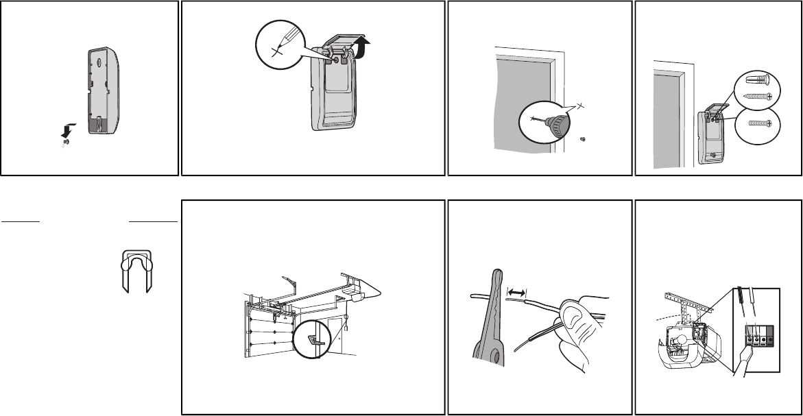
1Install the door control
Install the Door Control
To prevent possible SERIOUS INJURY or DEATH from electrocution:
• Be sure power is NOT connected BEFORE installing door control.
• Connect ONLY to 24 VOLT low voltage wires.
To prevent possible SERIOUS INJURY or DEATH from a closing garage door:
• Install door control within sight of garage door, out of reach of children at a minimum height of 5 feet
(1.5 m), and away from ALL moving parts of door.
• NEVER permit children to operate or play with door control push buttons or remote control
transmitters.
• Activate door ONLY when it can be seen clearly, is properly adjusted, and there are no
obstructions to door travel.
• ALWAYS keep garage door in sight until completely closed. NEVER permit anyone to cross path of
closing garage door.
INTRODUCTION
Compatible with MyQ™ and Security+®2.0
accessories. NOTE:Older LiftMaster
accessories and third party products are not
compatible.Your garage door opener is
compatible with up to 2 Smart Control Panels or
4 of any other Security+®2.0 door controls.
Install the door control within sight of the door at
a minimum height of 5 feet (1.5 m) where small
children cannot reach, and away from the
moving parts of the door.
NOTE: Your product may look different than
moving parts of the door the illustrations.
H14 (2)
Screw
6ABx1-1/4"
HARDWARE
H16 (2)
Drywall
Anchors
H15 (2)
Screw
6-32x1"
NOTE: For gang box installations it is not necessary to drill holes or install the drywall anchors. Use the existing holes in the gang box.
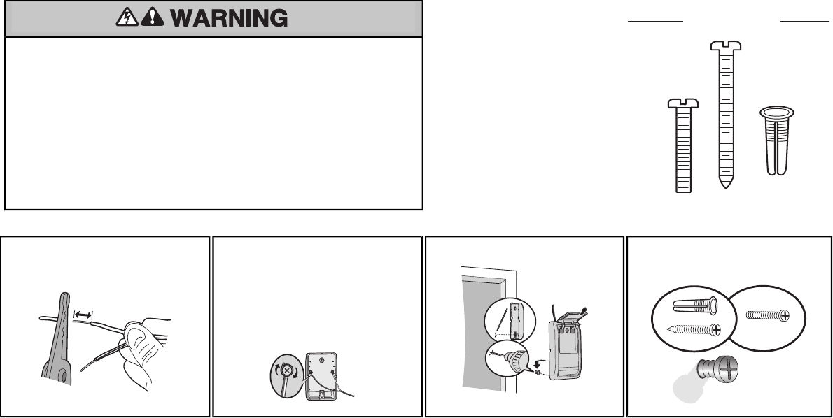
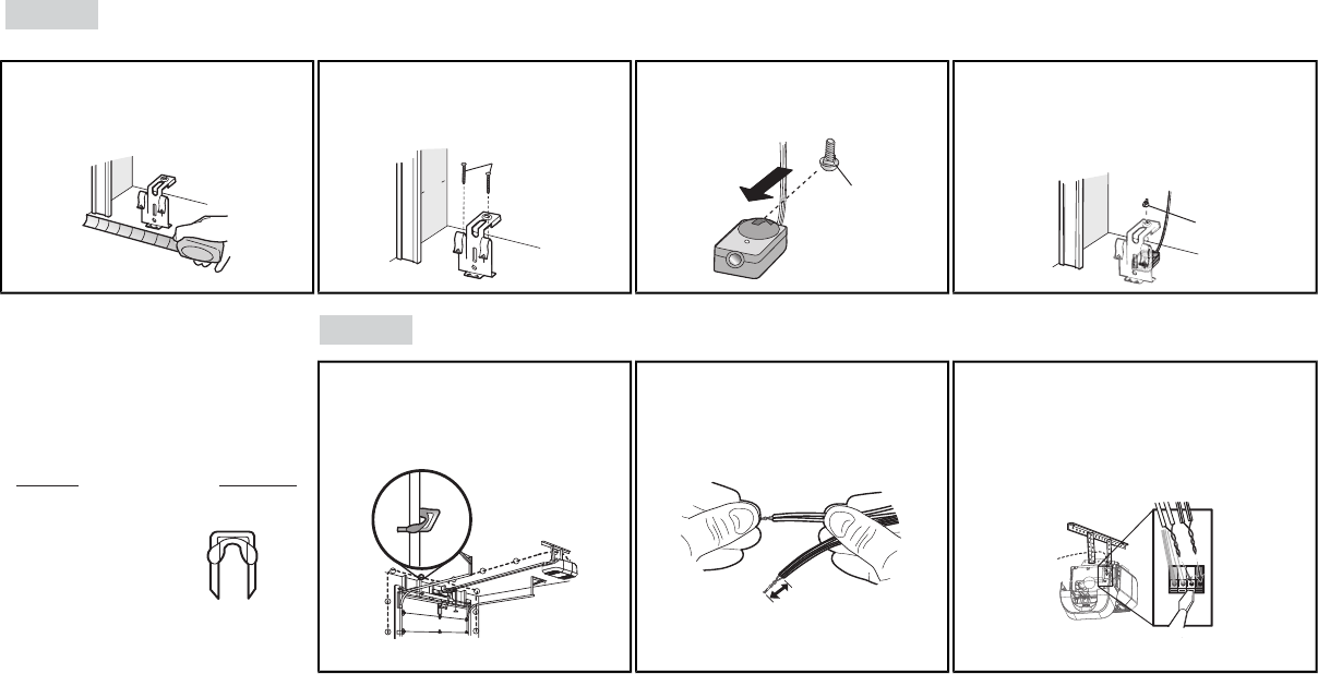
1.1 Strip 7/16 inch (11 mm) of insulation from
one end of the wire and separate the wires.
7/16"
(11 mm)
1.2 Connect one wire to each of the two screws
on the back of the door control. The wires
can be connected to either screw.
PRE-WIREDINSTALLATIONS:Choose
any two wires to connect, note which wires
are used so the correct wires are connected
at the garage door opener in a later step.
1.3 Mark the location of the bottom mounting
hole and drill a 5/32 inch (4 mm) hole.
Wall
1.4 Install the bottom screw, allowing 1/8 inch
(3 mm) to protrude from the wall.
H15
DRYWALL
GANG BOX
H14
H16
15
k
Install the Door Control
1.5 Position the bottom hole of the door
control over the screw and slide
down into place.
1.6 Lift the push bar up and mark the top hole. 1.7 Remove the door control from the wall
and drill a 5/32 inch (4 mm) hole for
the top screw.
1.8 Position the bottom hole of the
door control over the screw and
slide down into place. Attach the
top screw.
DRYWALL
H14
H16
H15
GANG BOX
2Wire the door control to the garage door opener
HARDWARE
H17 (10)
Insulated Staple
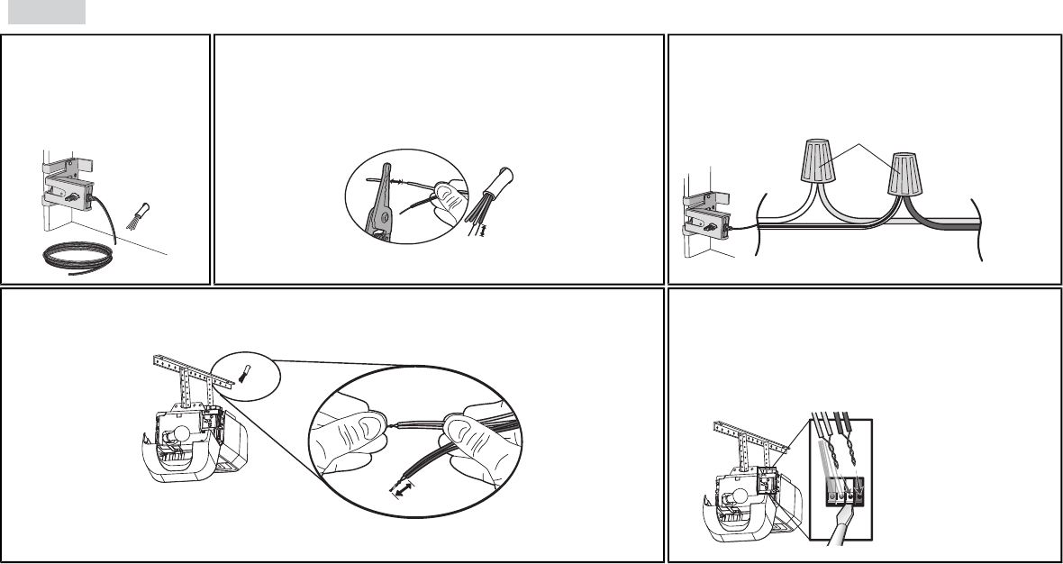
PRE-WIRED INSTALLATIONS: When wiring
the door control to the garage door opener
make sure you use the same wires that are
connected to the door control.
2.1 Run the white and red/white wire from the door control to
the garage door opener. Attach the wire to the wall and
ceiling with the staples (H17) (not applicable for gang box
or pre-wired installations). Do not pierce the wire with the
staple as this may cause a short or an open circuit.
H17
2.2 Strip 7/16 inch (11 mm) of insulation
from the end of the wire near the
garage door opener.
7/16"
(11 mm)
2.3 Connect the wire to the red and
white terminals on the garage
door opener. To insert or
release wires from the terminal,
push in the tab with screwdriver
tip.
RED
WHITE
WHITE
GREY
WHI
WHITE
E
16
3Attach the warning labels
Install the Door Control
3.1 Attach the entrapment warning label on the wall near the door control with tacks or
staples.
3.2 Attach the manual release/safety reverse test label in a visible location on the inside of
the garage door.
17
Introduction
Be sure power is NOT connected to the garage
door opener BEFORE installing the safety
reversing sensor.
To prevent SERIOUS INJURY or DEATH from
closing garage door:
• Correctly connect and align the safety
reversing sensor. This required safety
device MUST NOT be disabled.
• Install the safety reversing sensor so beam
is NO HIGHER than 6" (15 cm) above
garage floor.
Install the Protector System®
IMPORTANTINFORMATIONABOUTTHESAFETYREVERSINGSENSORS
The safety reversing sensors must be connected and aligned correctly before the garage door opener will move in the down direction.
The sending sensor (with an amber LED) transmits an invisible light beam to the receiving sensor (with a green LED). If an obstruction breaks the light
beam while the door is closing, the door will stop and reverse to the full open position, and the garage door opener lights will flash 10 times.
NOTE: For energy efficiency the garage door opener will enter sleep mode when the door is fully closed. The sleep mode shuts the garage door
opener down until activated. The sleep mode is sequenced with the garage door opener light bulb; as the light bulb turns off the sensor LEDs will turn
off and whenever the garage door opener lights turn on the sensor LEDs will light. The garage door opener will not go into the sleep mode until the
garage door opener has completed 5 cycles upon power up.
When installing the safety reversing sensors check the following:
• Sensors are installed inside the garage, one on either side of the door.
• Sensors are facing each other with the lenses aligned and the receiving sensor lens does not receive direct sunlight.
• Sensors are no more than 6 inches (15 cm) above the floor and the light beam is unobstructed.
Invisible Light Beam
Protection Area
Safety Reversing Sensor
6" (15 cm) max. above floor Safety Reversing Sensor
6" (15 cm) max. above floor
Install the Protector System®
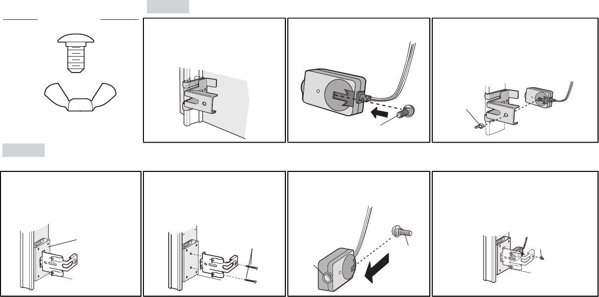
1Install the Safety Reversing Sensors
The safety reversing sensors can be attached to the door track, the wall, or the floor. If the door track will not support the sensor bracket a wall installation is recommended. Choose one of the following installations.
HARDWARE
H12 (2)
Carriage Bolt
1/4"-20x1/2"
H13 (2)
Wing Nut
1/4"-20
OPTION A DOOR TRACK INSTALLATION
1.1A Slide the curved arms of the sensor
bracketaround the edge of the door
track. Snap into place so that the
sensor bracket is flush against the
track.
1.2A Slide the carriage bolt (H12) into the
slot on each sensor.
H12
1.3A Insert the bolt through the hole in the sensor
bracket and attach with the wing nut (H13). The
lenses on both sensors should point toward
each other. Make sure the lens is not obstructed
by the sensor bracket.
H13
OPTION B WALLINSTALLATION
If additional clearance is needed an extension bracket (not provided) or wood blocks can be used. Make sure each bracket has the same amount of clearance so they will align correctly.
1.1B Position the sensor bracket against the
wall with the curved arms facing the
door. Make sure there is enough
clearance for the beam to be
unobstructed. Mark holes.
(not provided)
1.2B Drill 3/16 inch pilot holes for each
sensor bracket and attach the sensor
brackets to the wall using lag screws
(not provided).
Inside
Garage
Wall
(not provided)
1.3B Slide the carriage bolt (H12) into the
slot on each sensor.
H12
Lens
1.4B Insert the bolt through the hole in the sensor
bracket and attach with the wing nut (H13). The
lenses on both sensors should point toward
each other. Make sure the lens is not
obstructed by the sensor bracket.
H13
18
Install the Protector System®
1 Install the Safety Reversing Sensors
OPTION C FLOOR INSTALLATION
Use an extension bracket (not provided) or wood black to raise the sensor bracket if needed.
1.1C Carefully measure the position of both
sensor brackets so they will be the same
distance from the wall and unobstructed.
1.2C Attach the sensor brackets to the floor
using concrete anchors (not
provided).
Inside
Garage
Wall
(not provided)
1.3C Slide the carriage bolt (H12) into the
slot on each sensor.
H12
1.4C Insert the bolt through the hole in the sensor
bracket and attach with the wing nut (H13). The
lens on both sensors should point toward each
other. Make sure the lens is not obstructed by
the sensor bracket.
H13
2 Wire the Safety Reversing
Sensors OPTION A INSTALLATION WITHOUT PRE-WIRING
PRE-WIRED INSTALLATIONS: If your garage
already has wires installed for the safety
reversing sensors, refer to the instructions on the
following page.
HARDWARE
H17 (10)
Insulated Staple
2.1A Run the wire from both sensors to the
garage door opener. Attach the wire to
the wall and ceiling with the staples
(H17).
H17
2.2A Strip 7/16 inch (11 mm) of insulation
from each set of wires. Separate the
wires. Twist the white wires together.
Twist the white/black wires together.
7/16"
(11 mm)
2.3A Insert the white wires into the white terminal on
the garage door opener. Insert the white/black
wires into the grey terminal on the garage door
opener. To insert or remove the wires from the
terminal, push in the tab with a screwdriver tip.
RED
WHITE
WHITE
GREY
D
RED
W
RE
GR
GREY
WH
WHIT
19
Install the Protector System®
OPTION B PRE-WIRED INSTALLATION
2.1B Cut the end of the safety
reversing sensor wire, making
sure there is enough wire to
reach the pre-installed wires
from the wall.
2.2B Separate the safety reversing sensor wires and strip 7/16 inch (11 mm) of
insulation from each end. Choose two of the pre-installed wires and strip 7/16
inch (11 mm) of insulation from each end. Make sure that you choose the
same color pre-installed wires for each sensor.
7/16"
(11 mm)
7/16"
(11 mm)
Safety reversing sensor wires
Pre-installed
wires
2.3B Connect the pre-installed wires to the sensor wires with wire nuts
making sure the colors correspond for each sensor. For example,
the white wire would connect to the yellow wire and the white/black
wire would connect to the purple wire.
White
White/Black
Yellow
(for example)
Purple
(for example)
Not Provided
Pre-installed
wires
Safety reversing sensor wires
2.4B At the garage door opener, strip 7/16 inch (11 mm) of insulation from each end of the wires previously chosen for the
safety reversing sensors. Twist the like-colored wires together.
7/16"
(11 mm)
Yellow
Purple
2.5B Insert the wires connected to the white safety sensor wires to the
white terminal on the garage door opener. Insert the wires that are
connected to the white/black safety sensor wires to the grey
terminal on the garage door opener.
RED
WHITE
WHITE
GREY
D
W
RED
RE
GR
GREY
WH
WHIT
Purple
(for example)
Yellow
(for example)
To insert or remove the wires
from the terminal, push in the
tab with a screwdriver tip.
20
21
1 Connect Power
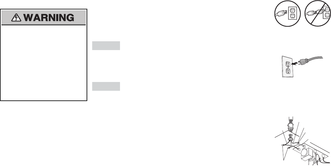
To prevent possible SERIOUS INJURY or
DEATH from electrocution or fire:
• Be sure power is NOT connected to the
opener, and disconnect power to circuit
BEFORE removing cover to establish
permanent wiring connection.
• Garage door installation and wiring MUST
be in compliance with ALL local electrical
and building codes.
• NEVER use an extension cord, 2-wire
adapter, or change plug in any way to make
it fit outlet. Be sure the opener is grounded.
To avoid installation difficulties, do not activate the garage door opener at this time.
To reduce the risk of electric shock, your garage door opener has a grounding type plug with a third
grounding pin. This plug will only fit into a grounding type outlet. If the plug doesn’t fit into your outlet,
contact a qualified electrician to install the proper outlet.
THERE ARE TWO OPTIONS FOR CONNECTION POWER:
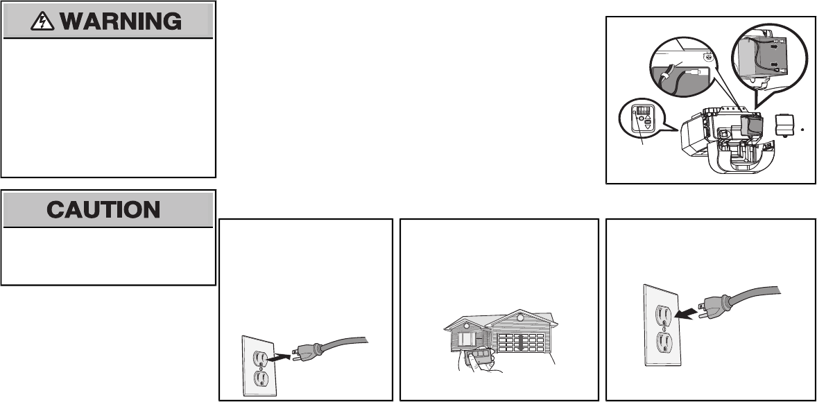
OPTION A TYPICAL WIRING
1.1A Plug in the garage door opener into a grounded outlet.
1.2A DO NOT run garage door opener at this time.
OPTION B PERMANENT WIRING
If permanent wiring is required by your local code, refer to the following procedure.
To make a permanent connection through the 7/8" hole in the top of the motor unit (according to local
code):
1.1B Be sure power is NOT connected to the opener, and disconnect power to circuit.
1.2B Remove the garage door opener cover and set aside.
1.3B Remove the attached green ground terminal.
1.4B Cut black and white wires and strip away 1/2" (1 cm) of insulation, 3" (7.5 cm) before spade
terminals.
1.5B Remove the power cord from opener.
1.6B Install a conduit or flex cable adapter to the 7/8" hole.
1.7B Run wires through conduit, cut to proper length and strip insulation.
1.8B Attach with wire nuts provided. Attach the ground wire to the green ground screw.The opener
must be grounded.
1.9B Properly secure wire under plastic ties so that wire does not come in contact with moving parts.
1.10B Reinstall the cover. DO NOT run garage door opener at this time.
Ground Tab
Green Ground
Screw
Ground Wire
Black
Wire
White Wire
PERMANENT WIRING CONNECTION
Wire Nuts
Power
22
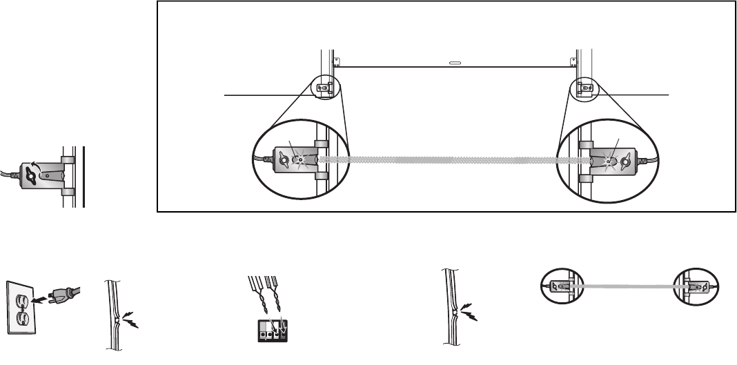
2Ensure the Safety Reversing Sensors are aligned
The door will not close if the sensors have not been
installed and aligned correctly.
When the light beam is obstructed or misaligned while
the door is closing, the door will reverse and the
garage door opener lights will flash ten times. If the
door is already open, it will not close. The sensors can
be aligned by loosening the wing nuts, aligning the
sensors, and tightening the wing nuts.
.
2.1 Check to make sure the LEDs in both sensors are glowing steadily.The LEDs in both sensors will glow steadily if they are aligned and
wired correctly.
Green LED
ROSNES GNIVIECERROSNES GNIDNES
Amber LED
If the receiving sensor is in
direct sunlight, switch it with
sending sensor so it is on the
opposite side of the door.
(invisible light beam)
IF THE AMBER LED ON THE SENDING SENSOR IS NOT GLOWING: IF THE GREEN LED ON THE RECEIVING SENSOR IS NOT GLOWING:
Make sure there is
power to the garage
door opener.
Make sure the
sensor wire is not
shorted/broken.
RED
WHITE
WHITE
GREY
Make sure the sensor has been wired
correctly: white wires to white terminal
and white/black wires to grey terminal.
Make sure the sensors are aligned.Make sure the sensor wire is
not shorted/broken.
3Ensure the Door Control is wired correctly
If the door control has been installed and wired correctly a message will display on the screen.
Power
23
Without a properly installed safety reversal
system, persons (particularly small children)
could be SERIOUSLY INJURED or KILLED by a
closing garage door.
• Incorrect adjustment of garage door travel
limits will interfere with proper operation of
safety reversal system.
• After ANY adjustments are made, the safety
reversal system MUST be tested. Door
MUST reverse on contact with 1-1/2" (3.8
cm) high object (or 2x4 laid flat) on floor.
To prevent damage to vehicles, be sure fully
open door provides adequate clearance.
TIP: If anything interferes with the door’s
upward travel it will stop. If anything interferes with
the door’s downward travel, it will reverse.
INTRODUCTION
Your garage door opener is designed with
electronic controls to make setup and
adjustments easy. The adjustments allow you
to program where the door will stop in the
open (UP) and close (DOWN) position. The
electronic controls sense the amount of force
required to open and close the door. The
force is adjusted automatically when you
program the travel and cannotbe changed.
PROGRAMMING BUTTONS
The programming buttons are located on the
left side panel of the garage door opener and
are used to program the travel.
UP (Open) DOWN (Close)
UP Button
Adjustment
Button
DOWN Button
PROGRAMMING BUTTONS
Adjustments
24
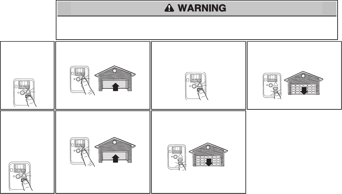
1Program the
Travel
Without a properly installed safety reversal system, persons (particularly small children) could be SERIOUSLY INJURED or KILLED by a closing garage door.
• Incorrect adjustment of garage door travel limits will interfere with proper operation of safety reversal system.
• ANY adjustments are made, the safety reversal system MUST be tested. Door MUST reverse on contact with 1-1/2" (3.8 cm) high object (or 2x4 laid flat) on floor.
1.1 Press and hold the
Adjustment Button until
the UP Button begins to
flash and/or a beep is
heard.
1.2 Press and hold the UP Button until the door is in
the desired UP position.
NOTE: The UPand DOWNButtons can be
used to move the door up and down as needed.
1.3 Once the door is in the desired UP position
press and release the Adjustment Button. The
garage door opener lights will flash twice and
the DOWN Button will begin to flash.
1.4 Press and hold the DOWN Button until the door
is in the desired DOWN position.
NOTE: The UPand DOWNButtons can be
used to move the door up and down as needed.
1.5 Once the door is in the
desired DOWN position
press and release the
Adjustment Button. The
garage door opener
lights will fl ash twice
and the UP Button will
begin to flash.
1.6 Press and release the UP Button. When the
door travels to the programmed UP position, the
DOWN Button will begin to flash.
1.7 Press and release the DOWN Button. The door
will travel to the programmed DOWN position.
Programming is complete.
*If the garage door opener lights are flashing 5
times during the steps for Program the Travel, the
programming has timed out. If the garage door
opener lights are flashing 10 times during the steps
for Program the Travel, the safety reversing
sensors are misaligned or obstructed (refer to
page 18). When the sensors are aligned and
unobstructed, cycle the door through a complete
up and down cycle using the remote control or the
UP and DOWN buttons. Programming is complete.
If you are unable to operate the door up and door,
repeat the steps for Programming the Travel.
Adjustments
25
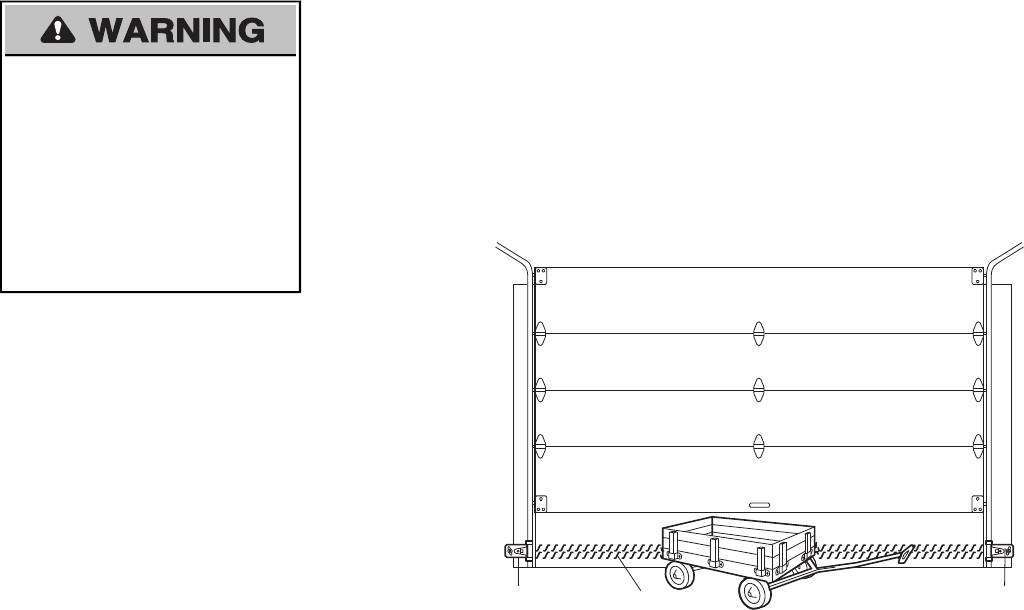
2Test the Safety Reversal System
Without a properly installed safety reversal system,
persons (particularly small children) could be
SERIOUSLY INJURED or KILLED by a closing
garage door.
• Safety reversal system MUST be tested every
month.
• After ANY adjustments are made, the safety
reversal system MUST be tested. Door MUST
reverse on contact with 1-1/2" high (3.8 cm)
object (or 2x4 laid flat) on the floor.
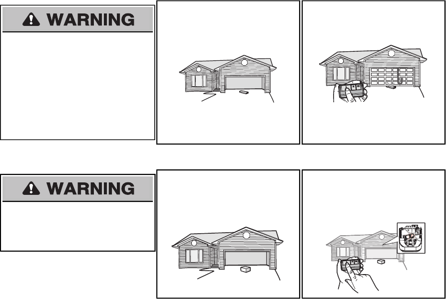
2.1 With the door fully open, place a 1-1/2
inch (3.8 cm) board (or a 2x4 laid flat) on
the floor, centered under the garage
door.
2.2 Press the remote control push button to
close the door. The door MUST reverse
when it makes contact with the board.
If the door stops and does not reverse on
the obstruction, the travel need to be
adjusted (refer to Adjustment Step 1).
Repeat the test. When the door reverses
upon contact with the 1-1/2 inch board,
remove the board and open/close the
door 3 or 4 times to test the adjustment.
If the test continues to fail, call a trained
door systems technician.
3Test the Protector System
Without a properly installed safety reversing
sensor, persons (particularly small children) could
be SERIOUSLY INJURED or KILLED by a closing
garage door.
3.1 Open the door. Place the garage door
opener carton in the path of the door.
3.2 Press the remote control push button to
close the door. The door will not move
more than an inch (2.5 cm), and the
garage door opener lights will flash 10
times.
The garage door opener will notclose
from a remote control if the LED in either
safety reversing sensor is off (alerting you
to the fact that the sensor is misaligned or
obstructed).
If the garage door opener closes the door
when the safety reversing sensor is
obstructed (and the sensors are no more
than 6 inches [15 cm] above the floor), call
for a trained door systems technician.
Adjustments
26
To reduce the risk of FIRE or INJURY to persons:
• Disconnect ALL electric and battery power
BEFORE performing ANY service or
maintenance.
• Use ONLY LiftMaster part # 485LM for
replacement battery.
• Do NOT dispose of battery in fire. Battery may
explode. Check with local codes for disposal
instructions.
1Install the battery
1.1 Unplug the garage door opener.
1.2 Open the light lens on the right side panel of the garage door opener. Use a Phillips
head screwdriver to remove the battery cover on the garage door opener.
1.3 Partially insert the battery into the battery compartment with the terminals facing out.
1.4 Connect red (+) and black (-) wires from the garage door opener to the
corresponding terminals on the battery.
1.5 Verify the battery wires are seated in the channel and replace the battery cover.
1.6 Plug in the garage door opener.
1.7 Wait for the green Battery Status LED to start flashing before proceeding to test the
battery.
Channel
Battery
Status LED
ALWAYS wear protective gloves and eye
protection when changing the battery or working
around the battery compartment.
2Test the battery
2.1 Unplug the garage door
opener. The battery status LED
will either glow solid orange
indicating opener is operating
on battery power or will flash
indicating low battery power.
NOTE: Make sure the garage
door opener is unplugged.
2.2 Open and close the door using the
remote control or door control.
NOTE: The garage door opener may
run slower if the battery is not fully
charged. The battery will take 24 hours
to fully charge.
2.3 Plug in the garage door opener. Verify
the battery status LED flashing green,
indicating the battery is charging.
Battery Backup
27
BATTERY STATUS LED
NOTE: The Battery Status LED is most visible
with the garage door opener light off. Battery
does not have to be fully charged to operate
the garage door opener.
Battery Status LED
GREEN LED:
All systems are normal.
• A solid green LED light indicates the
battery is fully charged.
• A flashing green LED indicates the battery
is being charged.
ORANGE LED:
The garage door opener has lost power and is
in battery backup mode.
• A solid orange LED with beep, sounding
approximately every 2 seconds, indicates
the garage door opener is operating on
battery power.
• A flashing orange LED with beep,
sounding every 30 seconds, indicates the
battery is low.
RED LED:
The garage door opener's 12V battery needs
to be replaced.
• A solid red LED with beep, sounding every
30 seconds, indicates the 12V battery will
no longer hold a charge and needs to be
replaced. Please call for replacement
battery to allow your system to operate
during a power outage.
CHARGE THE BATTERY
The battery will take 24 hours to fully charge. A fully charged battery supplies 12V DC to the garage door opener for one to two days of normal operation during an electrical power outage. Once the
battery voltage drops too low, the battery will no longer operate. After the electrical power has been restored, the battery will recharge within 24 hours. The battery will last 1 to 2 years with normal usage.
To obtain maximum battery life and prevent damage, disconnect the battery when the garage door opener isunplugged for an extended period of time.
NOTE: Door operation may be limited until the battery is fully charged. The garage door opener lights will not turn on during battery backup mode.
Battery Backup
28
IMPORTANT INSTALLATION INSTRUCTIONS
WARNING
To reduce the risk of SEVERE INJURY or DEATH:
1. READ AND FOLLOW ALL WARNINGS AND INSTRUCTIONS.
2. ALWAYS keep remote controls out of reach of children. NEVER permit children to operate or
play with garage door control push buttons or remote controls.
3. ONLY activate garage door when it can be seen clearly, it is properly adjusted, and there are
no obstructions to door travel.
4. ALWAYS keep garage door in sight until completely closed.
5. NO ONE SHOULD CROSS THE PATH OF THE MOVING DOOR. NO ONE SHOULD GO
UNDER A STOPPED, PARTIALLY OPENED DOOR.
6. If possible, use emergency release handle to disengage trolley ONLY when garage door is
CLOSED. Weak or broken springs or unbalanced door could result in an open door falling
rapidly and/or unexpectedly.
7. NEVER use emergency release handle unless garage doorway is clear of persons and
obstructions.
8. NEVER use handle to pull garage door open or closed. If rope knot becomes untied, you
could fall.
9. After ANY adjustments are made, the safety reversal system MUST be tested.
10. Safety reversal system MUST be tested every month. Garage door MUST reverse on
contact with 1-1/2" high (3.8 cm) object (or a 2x4 laid flat) on the floor.
11. ALWAYS KEEP GARAGE DOOR PROPERLY BALANCED (see page 2). An improperly
balanced door may NOT reverse when required and could result in SEVERE INJURY
or DEATH.
12. ALL repairs to cables,spring assemblies and other hardware, ALL of which are under
EXTREME tension, MUST be made by a trained door systems technician.
13. ALWAYS disconnectelectric power to garage door opener BEFORE making ANY
repairs or removing covers.
14. This operator system isequipped with an unattended operation feature. The door
could move unexpectedly. NO ONE SHOULD CROSS THE PATH OF THE MOVING
DOOR.
15. DO NOT enable the Timer-to-Close functionality if operating either one-piece or
swinging garage doors. To be enabled ONLY when operating a sectional door.
16. SAVE THESE INSTRUCTIONS.
Operation
29
Your garage door opener is equipped with features to provide you with greater control over your
garage door operation.
TIMER-TO-CLOSE
The Timer-to-Close feature automatically closes the door after a specified time period that can be
adjusted using the door control. Prior to the door closing there will be an audible and visual alert.
MyQ™
MyQ™ technology uses a 900MHz signal to provide two-way communication between the garage door
opener and MyQ™ accessories.Your garage door opener is compatible with up to 16 MyQ™
accessories.
SECURITY+®2.0 REMOTE CONTROLS AND DOOR CONTROLS
Your garage door opener is compatible with up to 2 Smart Control Panels or 4 of any other
Security+®2.0 door controls. Your garage door opener has already been programmed at the factoryto
operate with your remote control, which changes with each use, randomly accessing over 100 billion
new codes. The garage door opener is compatible with up to 40 remote controls.
THE PROTECTOR SYSTEM®(SAFETY REVERSING SENSORS)
When properly connected and aligned, the safety reversing sensors will detect an obstruction in the
path of the infrared beam. If an obstruction breaks the infrared beam while the door is closing, the door
will stop and reverse to full open position, and the opener lights will flash 10 times. If the door is fully
open, and the safety reversing sensors are not installed, or are misaligned, the door will not close from
a remote control. However, you can close the door if you hold the button on the door control or keyless
entry until the door is fully closed. The safety reversing sensors do no effect the opening cycle.
ENERGY CONSERVATION
For energy efficiency the garage door opener will enter sleep mode when the door is fully closed. The
sleep mode shuts the garage door opener down until activated. The sleep mode is sequenced with the
garage door opener light bulb; as the light bulb turns off the sensor LEDs will turn off and whenever the
garage door opener lights turn on the sensor LEDs will light. The garage door opener will not go into
the sleep mode until the garage door opener has completed 5 cycles upon power up.
LIGHTS
The garage door opener light bulbs will turn on when the opener is initially plugged in; power is
restored after interruption, or when the garage door opener is activated. The lights will turn off
automatically after 4-1/2 minutes. An incandescent A19 light bulb (100 wattmaximum) or for maximum
energy efficiency a 26W (100W equivalent) compact fluorescent light (CFL) bulb may be used.
LIGHTS FEATURE
The garage door opener is equipped with an added feature; the lights will turn on when someone
enters through the open garage door and the safety reversing sensor infrared beam is broken. For
added control over the light bulbs on your garage door opener, see the Door Control section.
USING YOUR GARAGE DOOR OPENER
The garage door opener can be activated through a wall-mounted door control, remote control,
wireless keyless entry or MyQ™ accessory.
When the door is closed and the garage door opener is activated the door will open. If the door senses
an obstruction or is interrupted while opening the door will stop. When the door is in any position other
than closed and the garage door opener is activated the door will close.If the garage door opener
senses an obstruction while closing, the door will reverse. If the obstruction interrupts the sensor beam
the garage door opener lights will blink 10 times. However, you can close the door if you hold the button
on the door control or keyless entry until the door is fully closed. The safety reversing sensors do no
effect the opening cycle.
The safety reversing sensor must be connected and aligned correctly before the garage door opener
will move in the down direction.
Features
30
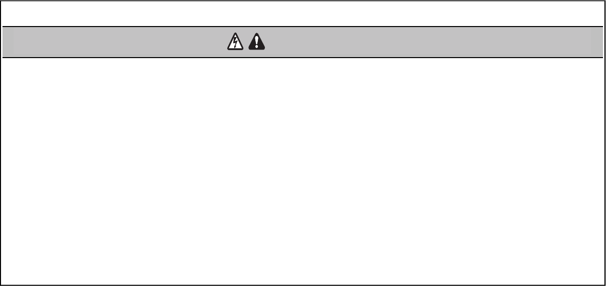
USING THE DOOR CONTROL
SYNCHRONIZETHEDOORCONTROL
To synchronize the door control to the garage door opener, press the push bar until the garage door
opener activates (it may take up to 3 presses). Test the door control by pressing the push bar, each
press of the push bar will activate the garage door opener.
Push Bar
LIGHT
button
Screen
Motion
Sensor
Navigation
Buttons
PUSH BAR
Press the push bar to open or close the door.
NAVIGATION BUTTONS
Use the navigation buttons to make selections and program features.
LIGHT BUTTON
Press the LIGHT button to turn the garage door opener lights on or off. When the lights are turned on
they will stay on until the LIGHT button is pressed again, or until the garage door opener is activated.
Once the garage door opener is activated the lights will turn off after the specified period of time (the
factory setting is 4-1/2 minutes). The LIGHT button will not control the lights when the door is in motion.
The duration of the light timing can be adjusted by accessing the menu using the navigation buttons.
HOLDOPEN
To temporarily suspend the Timer-To-Close (TTC) feature press and release the HOLDOPENbutton
(the HOLDOPENbutton will light solid). Press the HOLDOPENbutton again to resume normal
TTCoperation.
SCREEN
The screen will display the time and temperature until the menu button is pressed, and then it will
display the menu options. If there is a problem with the garage door opener the screen will display the
Diagnostic Code. Refer to the Troubleshooting section.
The following features are accessible through the screen using the navigation buttons:
LEARN A DEVICE
Any compatible remote controls, wireless keyless entry, or MyQ™ accessories can be programmed to
the garage door opener by accessing the menu and using the navigation buttons.
LOCK
The LOCK feature is designed to prevent activation of the garage door opener from remote controls
while still allowing activation from the door control and keyless entry. This feature is useful for added
peace of mind when the home is empty (i.e. vacation).
TIMER-TO-CLOSE (TTC) (881LMONLY)
DO NOT enable TTC if operating a one-piece door. TTC is to be used ONLY with sectional doors.
Factory default is set to off. TTC can be set to automatically close your garage door from the fully open
position after a specified period of time (1, 5, 10 minute intervals or a custom setting up to 99 minutes).
The garage door opener will beep and the lights will fl ash before closing the door. The screen on the
door control can display the status of the TTC. TTC WILL NOT work if the garage door opener is
operating by battery power or if the safety reversing sensors are misaligned. This feature is NOT
intended to be the primary method of closing the door.A keyless entry should be installed in the
event of an accidental lock out when using this feature.
NOTE: Before enabling the TTC for the first time, or if you experience a power outage, cycle the garage
door opener open and closed to allow the TTC to set.
AUTOMATIC LIGHT
Motion Sensor
Factory default is set to on. This feature will automatically turn on the garage door opener lights when
motion is sensed. The lights will come on for the set period of time, then shut off.
The lights will turn on when someone enters through the open garage door and the safety reversing
sensor infrared beam is broken. If using the garage door opener light as a work light disable the
Automatic Light Feature, otherwise the light will turn off automatically if you are beyond the range of the
sensor.
MAINTENANCE ALERT (MAS)
This feature assists the homeowner in ensuring the garage door opener system stays in good working
condition. A maintenance alert message will display on the screen indicating the garage door opener
may be in need of maintenance. The MAS feature MUST be activated at time of installation. The factory
setting is off.
Door Control
31
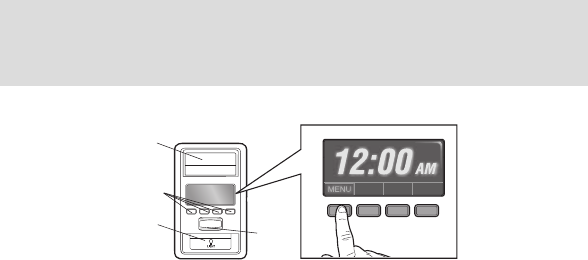
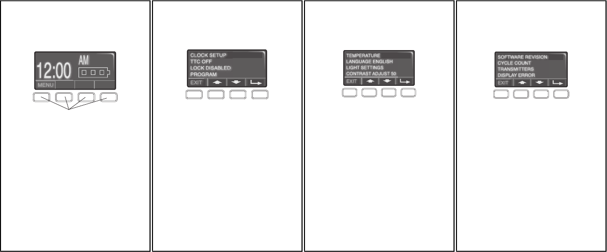
MENU NAVIGATION
The features on the door control can be programmed through a series of menus on the screen and the navigation buttons. Refer to the descriptions below.
SCREEN
The main screen displays the time, temperature,
and current battery charge (if applicable).
Navigation Buttons
FEATURES
Press the navigation button below "MENU" to view
the Features menu.
CLOCK SETUP: Set the time, choose 12 or 24
hour clock and show/hide clock.
TTC SETTINGS (for sectional doors ONLY):
Set the Timer-to-Close feature off/on and set the
time interval before door closes. NOTE: DO NOT
enable TTC if operating a one-piece door. TTC is
to be used ONLY with sectional doors.
LOCK: Enable/disable lock.
PROGRAM: Add remote controls, MyQ™ devices,
an extra remote button to control your garage door
opener lights, or a keyless entry.
SETTINGS
Press the navigation button below the down arrow
till you see TEMPERATURE to view the Settings
menu.
TEMPERATURE: Display the temperature in
Fahrenheit or Celsius and show/hide the
temperature.
LANGUAGE: Select a language.
LIGHT SETTINGS: Set duration for garage door
opener light to stay on after operation, selectable
range of 1-1/2 to 4-1/2 minutes. Turn the Motion
sensor off/on, and turn the entry light feature off/on.
CONTRAST: Adjust the contrast of the screen.
SERVICE
Press and hold the second navigation button, then
press the LIGHT button to view the Service menu.
SOFTWARE REVISION: Displays software version
information.
CYCLE COUNT ON/OFF: Turn the Maintenance
Alert (MAS) on/off.
TRANSMITTERS: Displays the number of remote
controls, MyQ™ devices, door controls and keyless
entries currently programmed to operate the
garage door opener.
DISPLAYERROR: Displays any errors that have
occurred.
To program a remote control or keyless entry to the garage door opener using the door control see page 32.
Door Control
32
Your garage door opener has been programmed at the factory to operate with your remote control. To program additional remote controls refer to the instructions provided with the additional remote controls
or visit www.liftmaster.com.
TO ADD, REPROGRAM,OR CHANGE A REMOTE CONTROL/KEYLESS ENTRY PIN USING THE DOOR CONTROL
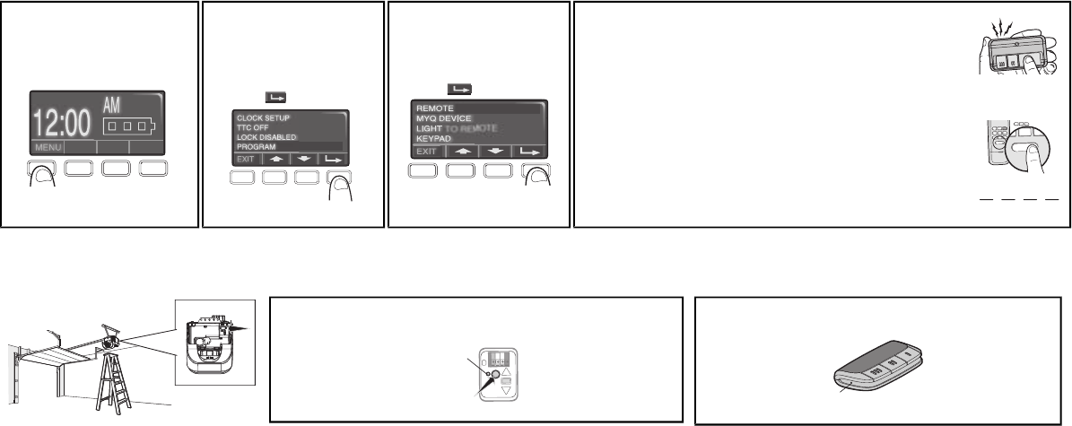
1Press the navigation button
below "MENU" to view the
Features menu.
2Use the navigation buttons
to scroll to "PROGRAM".
press
to continue.
3Select "REMOTE"or
"KEYPAD" to program from
the program menu.
TO REMOTE
press to continue.
4Remote Control:
Press the button on the remote control that you wish to operate your
garage door.
Keyless Entry:
Enter a 4-digit personal identification number (PIN) of your choice on
the keyless entry keypad. Then press the ENTERbutton.
OR
The garage door opener lights will flash (or two clicks will be heard) when
the code hasbeen programmed.
Repeat the steps above for programming additional remote controls or
keyless entry devices. If programming is unsuccessful, program the
remote using the learn button.
PIN
? ? ? ?
12ABC 3DEF
4GHI 5JKL 6MNO
7PRS 8TUV 9WXY
0 QZ
*
#
ENTER
0 QZ
*#
ENTER
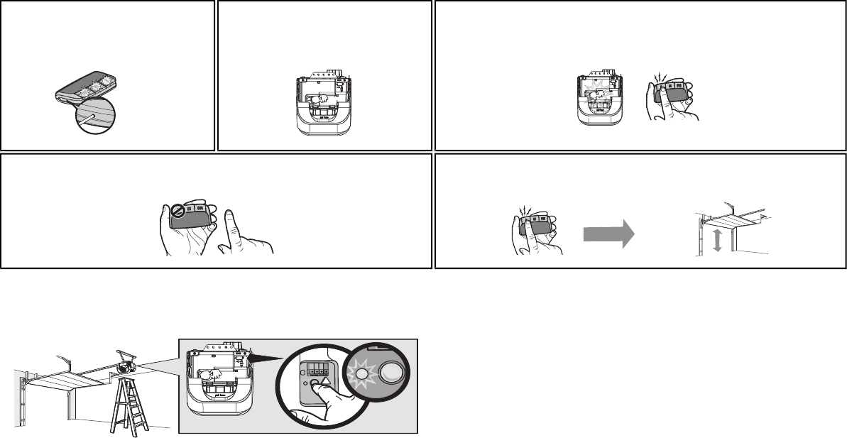
PROGRAM A REMOTE CONTROL USING THE LEARN BUTTON
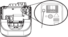
1Locate the Learn button on the garage door opener. NOTE:Your garage
door opener may look different.
Learn
DEL
Yellow
2Locate the Program Button on the side of the remote control.
Program Button
Remote Controls
33
3Using a safety pin or paper clip, press the
program button until the LEDs on the front of
the remote control turn on.
4Press and release the Learn button on the
garage door opener. The Learn LEDwill light.
Within 30 seconds...
5Press and release the remote control button you want to use...
Check to see if the garage door opener light bulb blinks. Ifnot, wait for the remote control LEDto
light solid then slowly press and release the remote control button again.
Repeat until the light bulb blinks. DONOTpress the button after the light bulb blinks.
6To exit programming mode, press any remote control button except the button that was just
programmed.
7To test, press the programmed button on the remote control... The garage door opener will
activate.
To Erase the Memory
ERASE ALL REMOTE CONTROLS AND KEYLESS ENTRIES
1Press and hold the learn button on garage door opener until the learn LED goes out
(approximately 6 seconds). All remote control and keyless entry codes are now erased.
Reprogram any accessory you wish to use.
ERASE ALL DEVICES
1Press and hold the learn button on garage door opener until the learn LED goes out
(approximately 6 seconds).
2Immediately press and hold the learn button again until the learn LED goes out. All codes are
now erased.
Reprogram any accessory you wish to use.
Remote Controls
34
To prevent possible SERIOUS INJURY or DEATH from a falling garage door:
• If possible, use emergency release handle to disengage trolley ONLY when garage door is
CLOSED. Weak or broken springs or unbalanced door could result in an open door falling rapidly
and/or unexpectedly.
• NEVER use emergency release handle unless garage doorway is clear of persons and
obstructions.
• NEVER use handle to pull door open or closed. If rope knot becomes untied, you could fall.
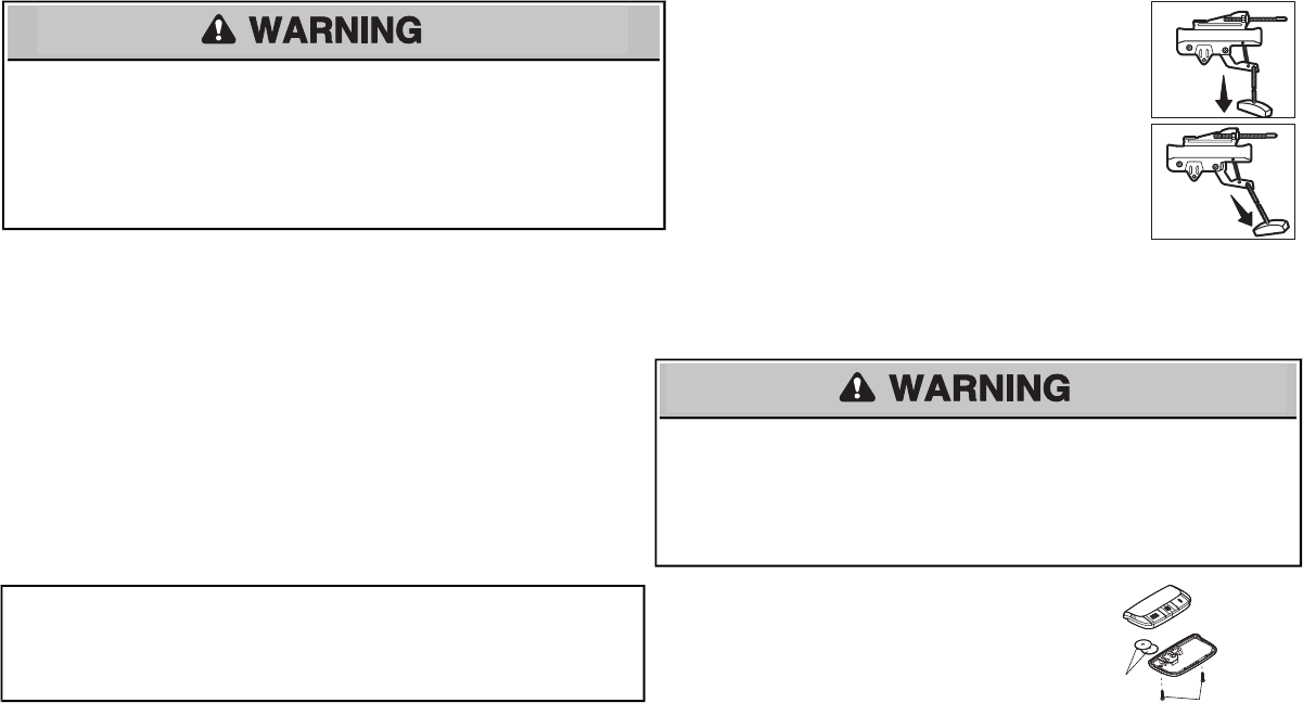
DISCONNECT THE TROLLEY
1The door should be fully closed if possible.
2Pull down on the emergency release handle.
RECONNECT THE TROLLEY
The lockout feature prevents the trolley from reconnecting
automatically.
1Pull the emergency release handle down and back (toward the
opener). The door can then be raised and lowered manually as
often as necessary.
2To disengage the lockout feature, pull the handle straight down.
The trolley will reconnect on the nextUP or DOWN operation,
either manually or by using the door control or remote control.
NOTICE
NOTICE
Maintenance
EVERY MONTH
• Manually operate door. If it is unbalanced or binding, call a trained door systems technician. Check
to be sure door opens and closes fully. Adjust if necessary (refer to Adjustment section). Repeat the
safety reverse test. Make any necessary adjustments (refer to Adjustment section).
EVERY YEAR
• Oil door rollers, bearingsand hinges. The garage door opener does notrequire additional
lubrication. Do not grease the door tracks.
EVERY TWO TO THREE YEARS
• Use a rag to wipe away the existing grease from the garage door opener rail. Reapply a small layer
of white lithium grease to the top and underside of the rail surface where the trolley slides.
• Test the battery and consider replacing the battery to ensure the garage door opener will operate
during an electrical power outage.
NOTICETo complywith FCC and or IndustryCanada rules(IC), adjustment or modifications of this receiver and/or transmitterare
prohibited, except for changing the code setting orreplacing the batteryTHEREARENOOTHERUSERSERVICEABLEPARTS.
Tested to Comply with FCCStandards forHome or office use. Operation is subject to the following tow conditions: (1) this device
maynot cause harmful interface, and (2)thisdevice must accept any interference received, including interference that may cause
undesired operation.
THE REMOTE CONTROL BATTERY
To prevent possible SERIOUS INJURY or DEATH:
• NEVER allow small children near batteries.
• If battery is swallowed, immediately notify doctor.
To reduce risk of fire, explosion or chemical burn:
• Replace ONLY with 3V2016 coin batteries.
• DO NOT recharge, disassemble, heat above 212°F (100°C) or incinerate.
To replace the batteries, remove the two screws and open the remote
control housing. Push the battery out of the holder for removal. Insert
replacement batteries positive side up (+).
Replace the batteries with only 3V2016 coin cell batteries. Dispose of
old batteries properly.
Batteries
Screws (2)
To Open the Door Manually

35
Diagnostic Chart
Your garage door opener is programmed with self-diagnostic capabilities. The UP and DOWN arrows on the garage door opener flash the diagnostic codes.
DIAGNOSTIC
CODE UP
ARROW DOWN
ARROW SYMPTOM CAUSE RESOLUTION
1-1 1 FLASH 1 FLASH The garage door opener will notclose
and the light(s) will flash
Safety sensors are not
installed, connected, or
wires may be cut
Inspectsensor wires for a disconnected or cut wire(s). If the sending sensor with the
amber LED is NOT lit, check the wire and connections for that sensor. If sending
sensor LED is lit, check the wire connections leading to the receiving sensor (green
LED). Reattach wire or replace wire (22 gauge wire) as needed. If pre-wired home,
check the splices. See page 18 for installation. Close the garage door using the
remote control or the door control.
1-2 1 FLASH 2 FLASHES
The garage door opener will notclose
and the light(s) will flash
Safety sensor wire
shorted or reversed
Inspectsensor wire for incorrect wiring or a pinched wire. If the sending sensor
(amber LED) is not lit, check the wire leading to and from that sensor. Check staple
points. Ifsending sensor LED is lit, check the wire leading to the receiving sensor
(green LED). Reattach wire or replace wire (22 gauge wire) as needed. If pre-wired
home, check the splices. See page 18 for installation. Close the garage door using
the remote control or the door control.
1-3 1 FLASH 3 FLASHES
Wall-mounted door control will not
function
The wires for the door
control are shorted or
the door control is faulty
Inspectdoor control wires for a short (staple in wire), replace wire (22 gauge wire) as
needed. After installing new door control wires, if door control still does not operate
garage door opener, replace the door control.
1-4 1 FLASH 4 FLASHES
The garage door opener will notclose
the door and the light(s) flash
Misaligned or
obstructed safety
sensors
Realign the receiving sensor (green LED) by ensuring the LED is steady and not
flickering. A flicker of the safety sensor LED indicates a misalignment.Make sure
nothing is hanging or mounted on the door interrupting the sensor’s path while
closing. Close the garage door using the remote control or the door control.
1-5 1 FLASH 5 FLASHES
The garage door opener clicks but no
movement
Bad logic board Replace the logic board.
The opener runs approximately 6-8"
and stops and/or reverses
Communication error to
travel module
Disconnect all power, remove cover, and locate the travel module. Ensure the wires
for travel module are connected, if wires are connected, then replace the travel
module.
Troubleshooting

36
DIAGNOSTIC
CODE
UP
ARROW DOWN
ARROW SYMPTOM CAUSE RESOLUTION
3-3 3 FLASHES 3 FLASHES The garage door opener is
idle and the battery LED is
constantly flashing green
Battery LED flashing
Green, charging circuit
stops and starts to drain
causing battery charging
status.
Replace the logic board.
4-1 4 FLASHES 1 FLASH Door is closing, stops and
reverses Obstruction, binding or
sticking door If your door is binding or sticking, contact a trained door systems technician. If your door is okay, reprogram
the travel, refer to page 24.
4-2 4 FLASHES 2 FLASHES The door stops while opening
for no apparent reason Obstruction, binding or
sticking door Manually open and close the door. Check for binding or obstructions. Refer to page 2.
4-3 4 FLASHES 3 FLASHES The door reverses for no
apparent reason or after
touching the floor
Obstruction, binding or
sticking door If your door is binding or sticking, contact a trained door systems technician. If your door is okay, reprogram
the travel, refer to page 24.
4-4 4 FLASHES 4 FLASHES My door reverses for no
apparent reason or after
touching the floor
Obstruction, binding or
sticking door Manually open and close the door. Check for binding or obstructions. Refer to page 2 .
4-5 4 FLASHES 5 FLASHES The opener runs
approximately
6-8" and stops and/or
reverses
Communication error to
travel module Disconnect all power, remove cover, and locate the travel module. Ensure the wires for travel module are
connected, if wires are connected, then replace the travel module.
4-6 4 FLASHES 6 FLASHES The door reverses for no
apparent reason while
traveling down
Safety sensors were
temporarily obstructed
or misaligned
Review Diagnostic Codes 1-1, 1-2, and 1-4 correct as necessary. If problem persists remove the sensors
from the brackets and realign the sensors ensuring the LED’s are steady and not flickering. Check for a
temporary obstruction such as a rope attached to the door. Excessive vibration on the door rails may cause
the sensors to be misaligned while the door is closing, secure rails or re-install the sensor brackets to the
wall or floor, refer to page 18.
These are additional troubleshooting issues that will not show up in the diagnostic codes:
My garage door opener beeps every 30 seconds:
Refer to the Battery Status LEDsection on page 27.
My remote control wilnot activate the garage door:
• Verify the lock feature is not activated on the door control.
• Reprogram the remote control.
• If the remote control will still not activate the door check the diagnostic codes to ensure
the garage door opener is working properly.
My garage door opener light(s) will not turn off when the door is open:
The garage door opener is equipped with a feature that turns the light on when the safety reversing
sensors have been obstructed or when the motion sensor on the door control detects movement in the
garage. These features can be disabled using the door control, refer to the Door Control section.
My neighbor’s remote control opens my garage door:
Erase the memory from your garage door opener and reprogram the remote control(s).
The LEDs on the door conrol blink:
If you have an Smart Control Panel installed and the TTC is set to a custom time, press the ONbutton on the
Premium Motion -Detecting Control Panel to set the time properly.
Troubleshooting
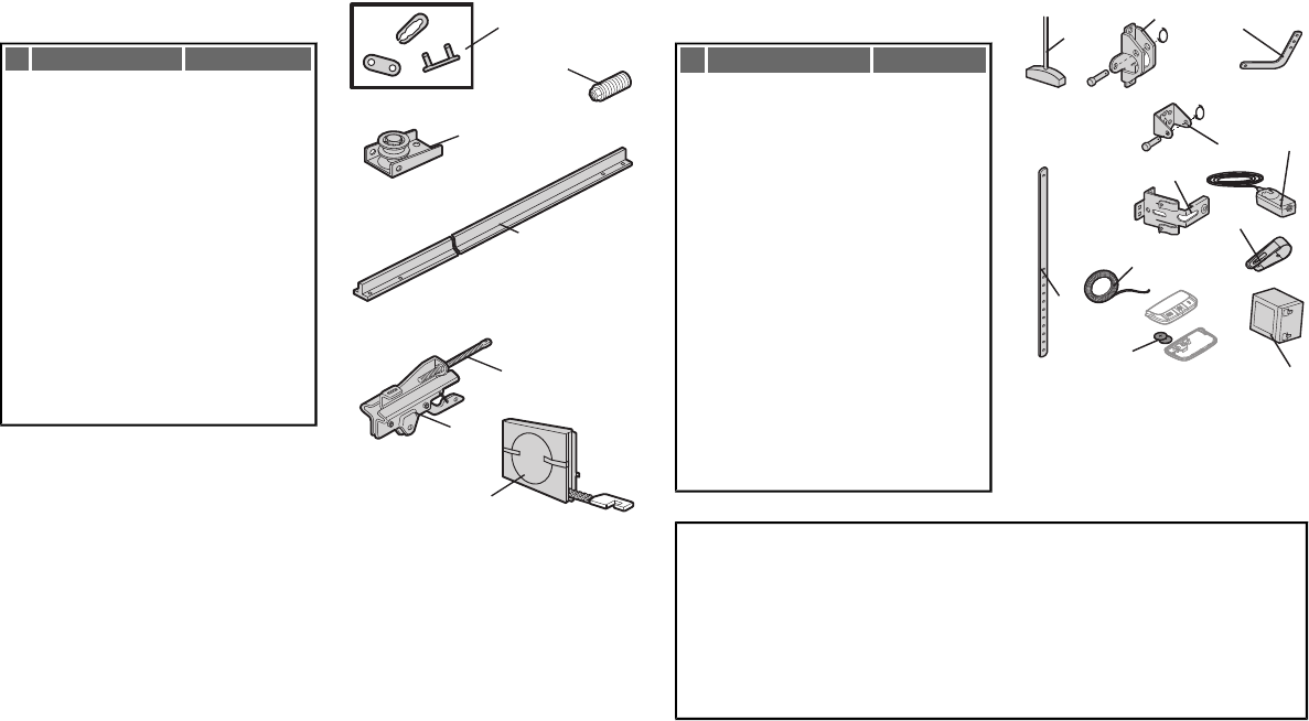
37
Rail Assembly Parts
DESCRIPTION PART NUMBER
1Belt - for 7 foot door
Belt - for 8 foot door
Belt - for 10 foot door
41A5434-11
41A5434-13
41A5434-14
2Belt Pulley Bracket 41B5424
3Master Link 4A1008
4One-Piece Rail
7 feet (2.1 m)
One-Piece Rail
8 feet (2.4 m)
One-Piece Rail
10 feet (3 m)
2777BD
2778BD
2770BD
5Trolley Assembly 41B3869-3A
6Tensioner Assembly 41B4103
7Trolley Threaded Shaft 109B48
1
3
4
5
7
6
2
Installation Parts
DESCRIPTION PART NUMBER
1Curved Door Arm 178B35
2Door Bracket with Clevis
Pin and Fastener
41A5047-1
3Emergency Release Rope
and Handle
41A2828
4Header Bracket with Clevis
Pin and Fastener
41A5047-2
5Remote Control Visor Clip 29B137
6Safety Sensor Bracket 41A5266-1
7Safety Sensor Kit
Receiving and sending
sensors with 3 feet (.9 m)
2-conductor wire
41A5034
8Straight Door Arm 178B34
9White and Red/White Wire 41C5141-1
10 3V2016 Lithium Battery 10A19
11 Battery Backup 485LM
Contact Information
Address repair parts order to:
The Chamberlain Group, Inc.
6050 S. Country Club Rd.
Tucson, AZ 85706
For installation and service information call:
1-800-528-9131
Or visit us online at:
www.liftmaster.com
Before calling, please have the model number of the garage door opener. If you are calling about a
Troubleshooting issue, it is recommended that you have access to your garage door opener while calling. If you
are ordering a repair part please have the following information: part number, part name, and model number.
NOTICE
UP
CEILING MOUNT ONLY
1
2
3
4
5
6
7
8
9
10
11
Repair Parts
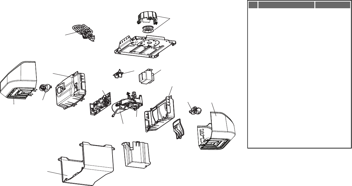
38
Garage Door Opener Parts
11
12
4
10
1
95
3
6
2
7
8
43
DESCRIPTION PART NUMBER
1Sprocket and Sprocket Cover
with Screws
41C589-2
2End Panel with labels, battery
cover and light socket
41D217
3Light Lens 41A7562
4Light Socket 41C279
5Transformer 41A7635
6Cover 41A7619
7Motor and Travel Module 41D1739-1
8Travel Module 41A7114-7
9End Panel with all labels and
light socket
41D216
10 Receiver Logic Board 45DCT
11 Line Cord 41B135
12 Filter Board with Screws 41B7611
NOT SHOWN
Wire Harness with Screws 41B7418
Battery Backup 485LM
Repair Parts
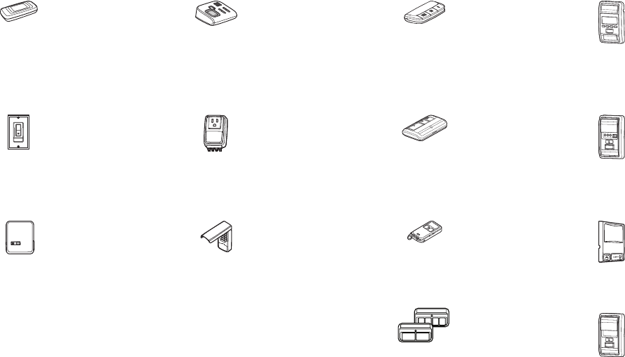
828LM MyQ™ Internet Gateway:
Internet enabled accessory
which connects to the computer
and allows you to monitor and
control garage door openers
and lighting accessories
powered by MyQ™ home
activation technology.
829LM Garage Door Monitor:
Monitor open/closed status for up to
4 MyQ™ compatible garage door
openers and close them from
anywhere in the home.
895MAX SECURITY+®2.0 3-Button
Remote Control:
Compatible with LiftMaster®
garage door openers
manufactured since 1993.
Includes visor clip.
880LM SECURITY+®2.0 Smart Control Panel®:
Displays temperature, time and system
diagnostics; includes a push bar to open
and close the door and a lock feature for
extra security.
823LM Remote Light Switch:
Automatically control your lights
using your garage door opener,
a Security+®2.0 remote control
or a MyQ™ Internet Gateway.
Simply replaces your current
wired wall switch.
990LM System Surge Protector:
The Garage Door Opener Surge
Protector is designed to protect
LiftMaster®garage door openers
against damage from lightning and
power surges. Easy to install.
893MAX SECURITY+®2.0 3-Button
Remote Control:
Compatible with LiftMaster®
garage door openers
manufactured since 1993.
Includes visor clip.
881LM SECURITY+®2.0 Motion Detecting Control
Panel with Timer-To-Close Control:
Multi-function door control with motion
sensor that automatically turns opener lights
on for 5 minutes when it detects a person
entering the garage. Sensor can be easily
deactivated when desired.
825LM Remote Light Control:
Automatically control your lights
using your garage door opener,
a Security+®2.0 remote control
or a MyQ™ Internet Gateway.
877MAX SECURITY+®2.0 Keyless Entry:
For use outside of the home to
enable access to the garage using
a 4-digit PIN. Works with ALL
LiftMaster®openers from 1999-
present. MyQ™ compatible.
890MAX SECURITY+®2.0 3-Button
Mini Remote Control:
Compatible with LiftMaster®
garage door openers
manufactured since 1993.
885LM SECURITY+®2.0 Wireless Door Control:
Push bar, light feature and auxiliary button.
Includes battery.
892LT/894LT 2 & 4 Button Learning Remote
Controls:
Works with any LiftMaster®
Garage Door opener
manufactured since 1993. Also
compatible with Encrypted DIP
for gate applications.
886LM SECURITY+®2.0 Motion Detecting
Control Panel:
Multi-function door control with motion
sensor that automatically turns opener
lights on for 5 minutes when it detects a
person entering the garage. Sensor can
be easily deactivated when desired.
Accessories
39

LIFTMASTER FIVE YEAR LIMITED WARRANTY
LIFETIME MOTOR AND BELT LIMITED WARRANTY
ONE YEAR LIMITED WARRANTY FOR EVERCHARGE®STANDBY POWER BATTERY
The Chamberlain Group, Inc. (“Seller”) warrants to the first retail purchaser of this product, for the residence in which this product is originally installed, that it is free from defect in materials and/or
workmanship for a period of 60 full months from the date of purchase and that the motor and belt are free from defect in materials and/or workmanship for a period of the lifetime of the product. The
proper operation of this product is dependent on your compliance with the instructions regarding installation, operation, and maintenance and testing. Failure to comply strictly with those instructions will
void this limited warranty in its entirety.
If, during the limited warranty period, this product appears to contain a defect covered by this limited warranty, call 1-800-528-9131; toll free, before dismantling this product. Then send this product, pre-
paid and insured, to our service center for warranty repair. You will be advised of shipping instructions when you call. Please include a brief description of the problem and a dated proof-of-purchase
receipt with any product returned for warranty repair. Products returned to Seller for warranty repair, which upon receipt by Seller are confirmed to be defective and covered by this limited warranty, will
be repaired or replaced (at Seller’s sole option) at no cost to you and returned pre-paid. Defective parts will be repaired or replaced with new or factory-rebuilt parts at Seller’s sole option.
ALL IMPLIED WARRANTIES FOR THE PRODUCT, INCLUDING BUT NOT LIMITED TO ANY IMPLIED WARRANTIES OF MERCHANTABILITY AND FITNESS FOR A PARTICULAR PURPOSE, ARE
LIMITED IN DURATION TO THE FIVE YEAR LIMITED WARRANTY PERIOD SET FORTH ABOVE EXCEPT THE IMPLIED WARRANTIES WITH RESPECT TO THE BATTERY, WHICH IS LIMITED IN
DURATION TO ONE YEAR, MOTOR AND BELT, WHICH ARE LIMITED IN DURATION TO THE LIFETIME LIMITED WARRANTY PERIOD FOR THE MOTOR AND BELT, AND NO IMPLIED
WARRANTIES WILL EXIST OR APPLY AFTER SUCH PERIOD. Some states do not allow limitations on how long an implied warranty lasts, so the above limitation may not apply to you. THIS
LIMITED WARRANTY DOES NOT COVER NON-DEFECT DAMAGE, DAMAGE CAUSED BY IMPROPER INSTALLATION, OPERATION OR CARE (INCLUDING, BUT NOT LIMITED TO ABUSE,
MISUSE, FAILURE TO PROVIDE REASONABLE AND NECESSARY MAINTENANCE, UNAUTHORIZED REPAIRS OR ANY ALTERATIONS TO THIS PRODUCT), LABOR CHARGES FOR
REINSTALLING A REPAIRED OR REPLACED UNIT, REPLACEMENT OF BATTERIES IN REMOTE CONTROL TRANSMITTERS AND LIGHT BULBS OR UNITS INSTALLED FOR NON-
RESIDENTIAL USE.
THIS LIMITED WARRANTY DOES NOT COVER ANY PROBLEMS WITH, OR RELATING TO, THE GARAGE DOOR OR GARAGE DOOR HARDWARE, INCLUDING BUT NOT LIMITED TO THE
DOOR SPRINGS, DOOR ROLLERS, DOOR ALIGNMENT OR HINGES. THIS LIMITED WARRANTY ALSO DOES NOT COVER ANY PROBLEMS CAUSED BY INTERFERENCE. ANY SERVICE
CALL THAT DETERMINES THE PROBLEM HAS BEEN CAUSED BY ANY OF THESE ITEMS COULD RESULT IN A FEE TO YOU. UNDER NO CIRCUMSTANCES SHALL SELLER BE LIABLE FOR
CONSEQUENTIAL, INCIDENTAL OR SPECIAL DAMAGES ARISING IN CONNECTION WITH USE, OR INABILITY TO USE, THIS PRODUCT. IN NO EVENT SHALL SELLER’S LIABILITY FOR
BREACH OF WARRANTY, BREACH OF CONTRACT, NEGLIGENCE OR STRICT LIABILITY EXCEED THE COST OF THE PRODUCT COVERED HEREBY. NO PERSON IS AUTHORIZED TO
ASSUME FOR US ANY OTHER LIABILITY IN CONNECTION WITH THE SALE OF THIS PRODUCT.
Some states do not allow the exclusion or limitation of consequential, incidental or special damages, so the above limitation or exclusion may not apply to you. This limited warranty gives you specific
legal rights, and you may also have other rights, which vary from state to state.
Warranty
© 2011, The Chamberlain Group, Inc.
114A4243B All Rights Reserved
