Light And Motion Bluefin Hc7 Users Manual
BLUEFIN HC7 to the manual 2e7d574c-64ee-4da5-bc47-f7c0171c9986
2015-02-09
: Light-And-Motion Light-And-Motion-Bluefin-Hc7-Users-Manual-571924 light-and-motion-bluefin-hc7-users-manual-571924 light-and-motion pdf
Open the PDF directly: View PDF ![]() .
.
Page Count: 32
BLUEFIN HC7
Owner’s Manual
www.uwimaging.com

Standard Warranty
Light & Motion provides a limited warranty to the original purchaser for the Bluefin HC7
housing against all defects in original workmanship and material, under normal use and service,
for one year from the date of purchase with the following exceptions: Lamps are warranted
for 30 days, batteries are warranted for 90 days, and battery chargers are only warranted for
use in the US and Canada. Using a battery charger in conjunction with a voltage converter is
NOT considered normal use, and chargers will not be warranted under such conditions. Light
& Motion will not be liable for any further loss, damages or expenses, including incidental or
consequential damages directly or indirectly arising from the sale or use of this product.
Light & Motion will not be liable for any further loss, damages, or expenses, including incidental
or consequential damages directly or indirectly arising from the sale or use of this product.
Products not manufactured by Light & Motion, such as strobes and strobe arms, are not
covered under the Light & Motion warranty. These products are covered by the Terms and
Conditions set forth by their respective manufacturers.
Fault Free Warranty (Optional)
For 24 months from warranty purchase date this product is warranted against any physical
damage or harm, from any cause, regardless of the fault of purchaser, limited only by intentional
damage. During the Fault-Free Warranty period, any damage to or defects in this product will
be repaired and any adjustments needed for the product to conform fully to factory prescribed
standards will be made, without charge. At our option, the product will be replaced without
charge (but only once during the Fault-Free Warranty period, and only if the serial number
is recognizable). If the product is replaced under the Fault-Free Warranty due to customer
negligence or internal disruption of the product, the replacement product will be covered only
by the Standard Warranty (up to the end of the original Fault-Free Warranty period). Also
included in the Fault-Free Warranty is one Light & Motion Annual Service. These warranties
extend only to the original purchaser through Light & Motion or an authorized dealer.
The Fault-Free Warranty does not cover the following: Loss of product as the result of theft,
misplacement, intentional damage or other cause. Accessories, monitors, accessories lenses
and pointer lights and chargers. Parts such as lamps, O-rings, and batteries that are wear
items. Damage due to tampering or repair by a non-authorized shop or person. Import duties,
customs clearance fees, and general expenses involving shipping to Light & Motion. Light &
Motion reserves the right to choose the return shipping method of warranted products.
Expedited shipping charges are purchaser’s responsibility. The expressed warranty set forth
herein is in lieu of all other warranties expressed or implied, including without limitation any
warranties of merchantability or fitness for a particular purpose, and all such warranties are
hereby disclaimed and excluded by the manufacturer. Repair or replacement of defective items
as provided above is the sole and exclusive remedy provided hereunder.
The Bluefin HC7 Fault Free Warranty is $500. Contact your Light & Motion retailer
or Light & Motion directly to activate your Fault Free Warranty.

Welcome
Congratulations on your purchase of a Bluefin HC7 video housing.
Please inspect the packaging of your product to verify that there was no damage during
shipping.
If you are not familiar with your camera’s features, please take time to become familiar with
the camera before you proceed in this manual. This manual assumes you have a working
knowledge of your camera and will only cover operational procedures related to the Bluefin
HC7 video housing.
Periodically refer to the website for instruction revisions: http://www.uwimaging.com
Caution - Caution - Caution - Caution
2
To increase your enjoyment and the life span of your equipment please take an extra minute to
review common errors which will result in equipment damage or destruction.
• Always remove batteries from battery pods before storage or travel.
Failure to do so may result in inadvertent ignition of lighting system and
possible heat or fire damage.
• Check the operation of all your equipment several weeks prior to your trip. If maintenance
or repair is necessary, then time is available for both shipping and repair scheduling.
• Never transport or ship the housing with the camcorder inside. This may damage your
camcorder.
• Never leave your housing in the rinse bucket. It may be damaged by other equipment.
• When removing the camcorder from the housing after a dive, do so in a dry controlled
environment away from other Scuba related equipment. This prevents water from other
equipment or water from another diver accidentally entering the housing.
• If a battery pod is flooded, immediately remove the battery. POD: rinse with fresh water
(good) or rubbing alcohol (better). Shake vigorously, towel dry, and leave the pod where
it can drain excess moisture. BATTERY: Dry the battery off, blow any water out of the
connectors, and then shake the battery to remove remaining moisture. If there is water
inside the battery do not attempt to use it again. If the battery seems dry inside,
allow it to dry for at least 24 hours, away from flammable items. Then, on land, charge the
battery and test your lights before attempting another dive.

Table of Contents
Getting Started ............................................................4
Camera Preparation ........................................................5
P-Menu Setup . . . . . . . . . . . . . . . . . . . . . . . . . . . . . . . . . . . . . . . . . . . . . . . . . . . . . . . . . . . . . 6
Mounting the Camera in the Housing .........................................10
Operation of the BlueFin....................................................10
Using the Bluefin in VTR Mode...............................................14
Lens Installation / Removal ..................................................15
Reversing Smart Grip Functions..............................................15
Bluefin Monitors - Getting Started............................................16
Bluefin Monitors - Bulkhead Installation . . . . . . . . . . . . . . . . . . . . . . . . . . . . . . . . . . . . . . . . 16
Compact Monitor Operation ................................................17
Remote Monitor Operation .................................................18
Charging the Remote Monitor ...............................................19
Diving Without a Monitor Attached...........................................19
Display Icons on Monitors ..................................................20
Bluefin Light Systems - Getting Started . . . . . . . . . . . . . . . . . . . . . . . . . . . . . . . . . . . . . . . . 20
Charging Batteries.........................................................22
Installing Batteries .........................................................22
Removing Batteries ........................................................23
Mounting Battery Pods .....................................................23
Connecting Lights to Battery Pods............................................23
Light Operation...........................................................23
Pre-Dive Checklist.........................................................24
First Time Use............................................................24
After Diving Care .........................................................24
Replacing Handle Batteries ..................................................25
Housing Storage...........................................................25
O-ring Care and Maintenance................................................26
Other Maintenance ........................................................27
Returning Products for Care.................................................28
Bluefin Accessories ........................................................29
3
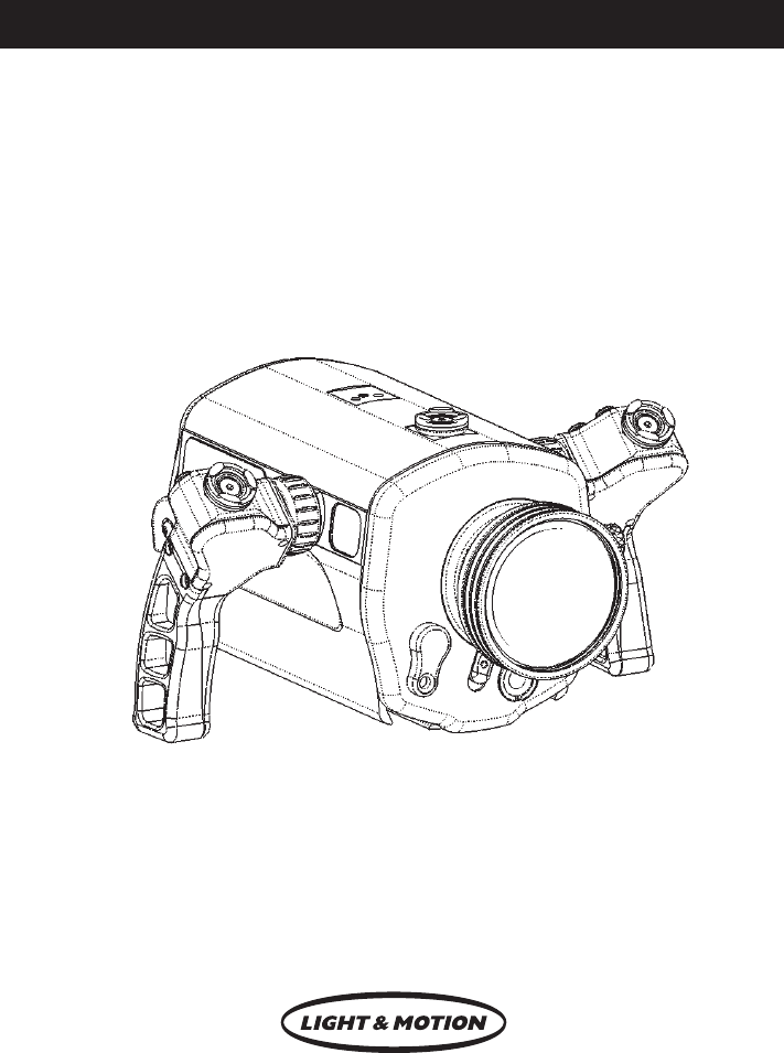
Getting Started
Illustrated below are the locations of Bluefin’s features and functions. Take time to familiarize
yourself with the housing.
Monitor Base
Light Arm Base
Lens Lock
ON/MODE Button
Monitor Bulkhead
Touch Screen Controls
Flip Filter Lever
Manual Button
Camera Control Knob
Self-Locking Rotary Latch
(one on each side)
5
Camera Preparation
1. Install a fully charged Sony “InfoLithium” H series battery pack (NP-FH100 recommended).
2. Install a HD DVC tape into your camcorder.
3. If still images are desired, install a Memory Stick Duo. Press the Flash button on the
right side of the camcorder to disable the camcorder’s built-in flash preventing the flash
from reflecting back into the camcorder’s lens.
4. Open the camcorder’s LCD screen. Rotate the LCD screen 180 degrees so the LCD
screen is facing away from the camcorder. Close the LCD screen against the camcorder
body so the screen is facing outward.
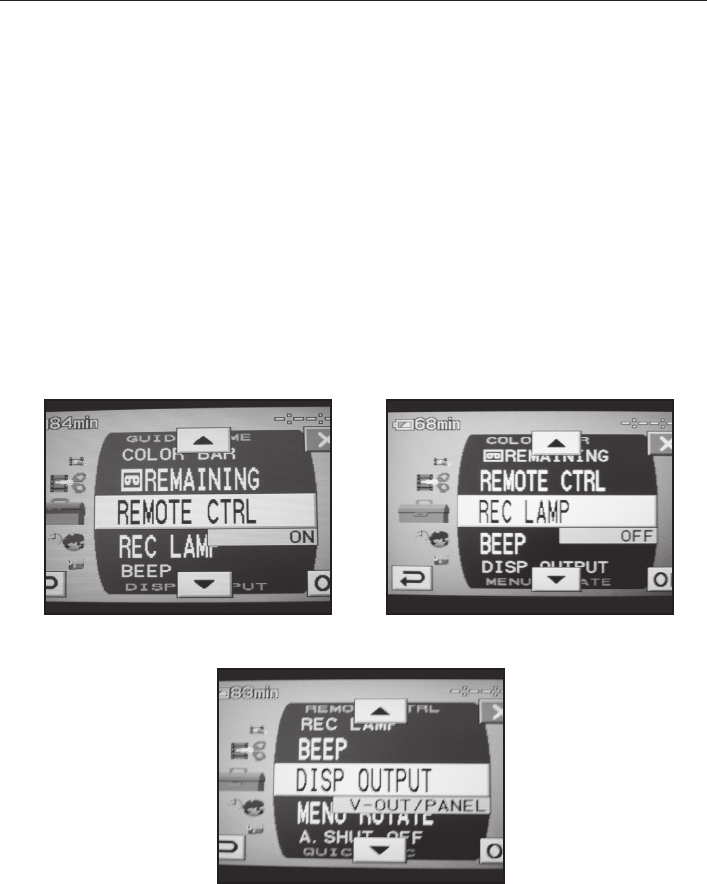
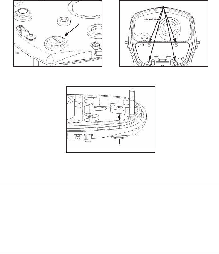
5. Enter the camera’s MENU and confirm or change the following settings. Scroll to the
STANDARD SET sub-menu and select it.
a. Change the Remote Control to the ON position (Refer Fig. 1).
b. Change the REC LAMP to the OFF position (Refer Fig. 2).
c. Change the DISP OUTPUT to the V-OUT/PANEL position (Refer Fig. 3).
If you’re using a monitor, this will display the camcorders icons, remaining battery
time, remaining tape time and other information in the Light & Motion monitor.
(Fig. 1) (Fig. 2)
(Fig. 3)
6
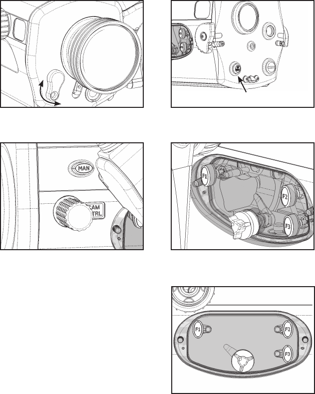
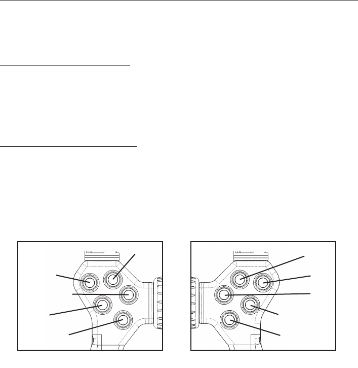
P-MENU Setup (See P-MENU Matrix on page 13)
The P-MENU is a customizable menu that
allows quick access to commonly used camera
features. This is very useful underwater since
controls such as White Balance can only be
accessed through the camera’s menu system.
The Bluefin HC7 uses an improved set of
window mounted controls for access to
the camera’s touch screen. These controls
consist of 3 fixed position buttons (labeled F1,
F2, and F3) and a single rotary control. The
rotary control allows access to the middle and
lower rows of screen buttons on the camera’s
P-MENU. The fixed position buttons allow
access to various buttons that display on the
screen for different controls.
The list on page 9 shows what camera menu items are usable in the Bluefin HC7. Some of these
menu items are on the P-MENU of the camera in its factory condition (or after the P-MENU has
been reset). And some will need to be added to the P-MENU. Because the rotary control can
only reach the middle and bottom screen buttons of the P-MENU, you may need to configure
the position of the items on the P-MENU that you want to access while the camera is in the
housing.
The following instructions show how to modify the P-MENU prior to loading the camera into
the Bluefin HC7. Instructions are included to reset the P-MENU, to sort a menu item to a differ-
ent position on the P-MENU, and to add an item to the P-MENU that is not on the P-MENU in
its factory condition (Refer Fig. 4).
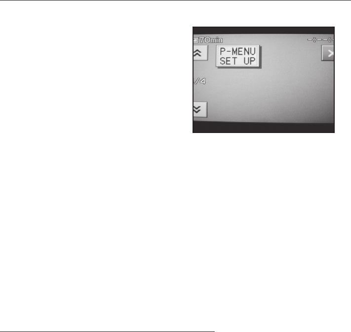
Reset the P-MENU to its factory condition
1. Turn the camera on in CAMERA-TAPE mode.
2. Press the P-MENU button in the lower right corner of the touch screen.
3. Press the up arrow button in the upper left corner of the touch screen.
4. Press the P-MENU SET UP button. (Note that the P-MENU SET UP button is always the last
button on the P-MENU).
5. Press RESET in the lower right position.
6. Press YES in the left position.
7. Press YES in the right position.
The camera’s P-MENU has now been reset to its factory condition.
(Fig. 4)

7
Sort an item on the P-MENU
The instructions below will use the X. V. Color control as an example of how to sort an item on
the P-MENU. X. V. COLOR is an emerging standard that expands the color range used during
capture and display of moving images. The HDR-HC7 camcorder supports this standard. But, the
position of the control that turns it on needs to be moved to allow use of the control with the
Bluefin HC7. Take the following steps to move this control.
1, If you have not just done so, reset the P-MENU by following the instructions above. (You
don’t always want to reset the P-MENU as part of sorting items but it makes this example
easier to understand.)
2. Go to the last page of the P-MENU and press the P-MENU SET UP button.
3. Press the SORT button in the lower left position.
4. Press the up arrow button in the upper left corner of the touch screen.
5. Press the X. V. COLOR button (this selects the X. V. COLOR button as the one to be
moved.
6. Press the up arrow button in the upper left corner twice. This moves the X. V. COLOR
button from position 14 to position 12. (The button position numbers only show up while
you are moving the buttons)
7. Press the OK button in the lower right corner.
8. Press the END button in the upper right corner.
The effect of this move is to put the X. V. Color button in the bottom right corner of the
second P-MENU screen. Moving it up shifts all the items between its original position and its final
position. So, it is a good idea to figure out what buttons you want where and then position them
one at a time starting with the lowest button position numbers and working to the highest but-
ton position numbers.

8
Add an item to the P-MENU
Some items that are useful during underwater photography are not on the P-MENU in its factory
condition. But these items can be moved to the P-MENU to allow access to them in the Bluefin
HC7. ZEBRA will be used as an example of how to add an item to the P-MENU.
ZEBRA displays diagonal stripes in the image in areas where the brightness is at or above a
preset value. The stripes are not recorded. ZEBRA can be useful in understanding if part of the
image will be overexposed.
ZEBRA is in the camera menu under CAMERA SET and can be added to the P-MENU so it can
be used in the Bluefin HC7. Take the following steps to add ZEBRA to the P-MENU.
1. Turn the camera on in CAMERA-TAPE mode.
2. Press the P-MENU button in the lower right corner of the touch screen.
3. Go to the last page of the P-MENU and press the P-MENU SET UP button.
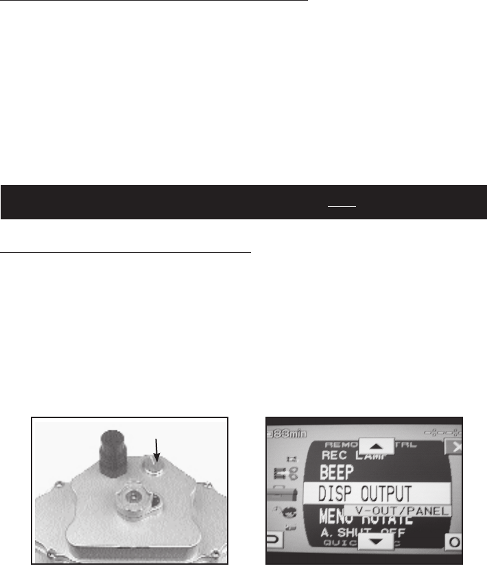
4. Press the ADD button in the upper left corner (Refer Fig. 5).
5. Press the OK button in the lower right corner to enter the CAMERA SET list. (Adding items
from other lists will require scrolling to that list first)
6. Press the down arrow until ZEBRA is selected (17 times!).
7. Press the OK button in the lower right corner.
8. Press the YES in the left position (Refer Fig. 6).
If this is the first item added to the P-MENU in its factory condition, the effect will be to put it at
the end of the list just before P-MENU SET UP. A new page will be created in the P-MENU and
P-MENU SET UP will be the only button on the new page. The added item will be in the lower
right position on the third page of the P-MENU.
If you have already added items to the P-MENU, the new item may not be in the middle or lower
button positions. Because the rotary control can only access items in the middle or lower posi-
tions, you may need to move the newly added item to allow access in the Bluefin HC7.
(Fig. 5) (Fig. 6)

Sony HC7 Functions usable in
Bluefin HC7 Video Housing
On HC7 P-Menu
after RESET
Required Change to P-Menu
Position after RESET
Scene Select
Yes
None
Smth Slw Rec
TeleMacro
Fader
Exposure**
Move to mid or lower P-Menu positions
Shutter Speed**
AE Shift**
None
WB Shift**
White Bal (except “Outdoor”)
X.V. Color Move to mid or lower P-Menu positions
Dial Set
None
Beep
Language
Focus**
No Add and move to mid or
lower P-Menu positions
Quick Record
Auto Slw Shtr
Color Slow S
Zebra
Histogram
Self Timer
Digital Zoom
Steady Shot
Conv. Lens
Pict. Effect
Rec. Format
Component
i.Link Conv.
TV Type
Status Check
Guide Frame
Color Bar
Tape Remaining
Remote Ctrl.
Rec. Lamp
Disp. Output
Menu Rotate
A. Shutoff
World Time
P-Menu Matrix
**Function also available on CAM CTRL Dial.

Mounting the Camera
1. Remove the rear plate by pushing the Latch Locks in and rotating the latches down and
forward of the housing body (Refer Fig. 8).
2. Remove the Camera Tray.
a. Push forward on the Camera Tray.
b. Press the Camera Tray Release Latch down (Refer Fig. 9).
The Camera Tray is spring loaded and will slide out of the housing.
3. Position the Camera Tray underneath the camera. The camera’s alignment hole (forward of
the camera’s threaded hole) should fit over the pin in the camera tray.
4. Use the Mounting Screw to secure the Camera Tray to the camera body. It is important
that the screw be snug to prevent the camera from moving.
5. Open the connector cover under the screen on the camera and plug the end of the long
cable into the blue LANC jack (Refer Fig. 10).
6. Insert the video cable into the A/V OUT connector on the rear of the camera
(Refer Fig. 11).
7. Connect microphone (Refer Fig. 11).
8. On the housing, pull the CAM CTRL knob out and rotate it slightly until it catches in the
out position. You need to do this each time the camera is installed or removed from
the housing.
9. Align the front of the Camera Tray with the base of the housing.
10. Slide the Camera Tray forward until the latch engages.
11. Rotate the CAM CTRL dial slightly until it returns to its inner position.
12. Replace rear plate.
13. Align guide pins and connector into base of Camera Tray.
14. Rotate both latches evenly until they lock. Ensure the rear plate draws in straight
Operation
Left Smart Grip Controls (Refer Fig. 12)
Far - Moves focus point further from camcorder.
Near - Moves focus point closer to camcorder.
Photo - Records still video capture to Memory Stick (in either video or photo mode).
Light - After initial power up from battery pod, cycles Elite Lights through three output
levels. Press and hold for three seconds to turn lights off. For Pro Lights, it turns them
on or off.
Photo Dis. - Non-operational
10
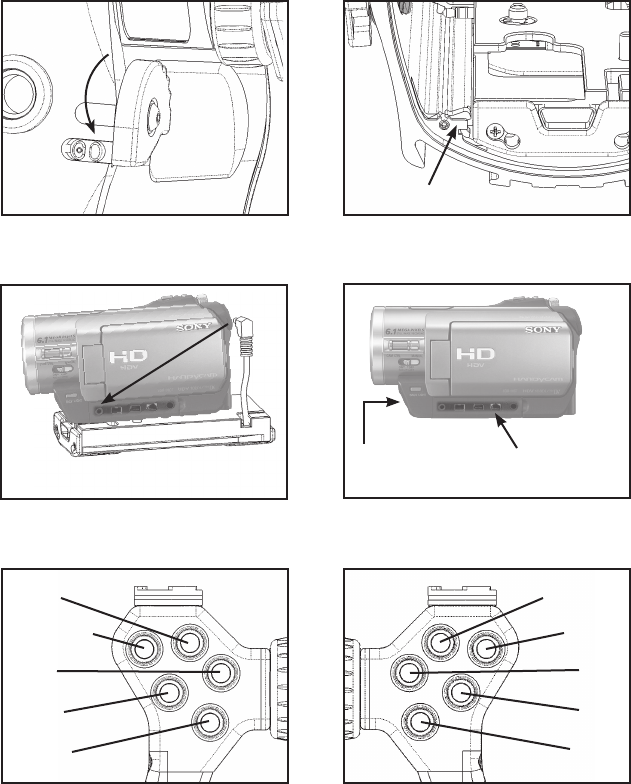
(Fig. 8) (Fig. 9)
LANC cable
(Fig. 10)
11
(Fig. 12) (Fig. 13)
A/V Out
(Fig. 11)
Camera Tray Release
Lights
Photo Dis.
Far/+
Photo
Near/-
MOM AF
AF/Off
Tele
REC
Wide
Microphone
(on front of camera)

12
Right Smart Grip Controls (Refer Fig. 14)
Tele - Zooms camcorder to telephoto.
Wide - Zooms camcorder to wide angle.
Rec - Toggles camcorder between record/standby.
Mom.Af - Press and hold this button to put the camcorder into “momentary AF”.
Camcorder remains in AF as long as the button is pressed. Once released,
the camcorder switches to manual focus. This is useful in stopping the camcorder
from “seeking” when filming in a low contrast environment. To return the camcorder
to AF, press the AF/OFF button.
Af / Off - (dual function) - Press and release, to switch camcorder to auto focus.
Press and hold for 3 seconds, to turn the camcorder off.
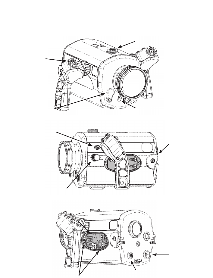
Front Plate (Refer Fig. 14)
Flip Filter - Rotate lever to engage or disengage color correction filter.
Rear Plate (Refer Fig. 15)
On/Mode - Turns the camcorder on and cycles through modes.
Housing Left Side (Refer Fig. 16)
Manual - Activates the camera’s manual button. Briefly pushing this button activates
manual control of the active function. You can change the active function by pushing
and holding the button until the menu of options appears on the display.
Camera Control Knob - Adjusts the function activated with the Manual button.
Touch Screen Controls - Three buttons and one rotary control allow partial access
to the camera’s P-Menu. Rotate the knob to position the internal selector over a
button on the camera’s screen. Press the buttons to access various controls on the
camera’s screen (Refer Fig. 17a and 17b).
13
(Fig. 14) (Fig. 15)
(Fig. 16) (Fig. 17a)
(Fig. 17b)
ON/MODE Button
14
Using the Bluefin in VTR Mode
Push the Bluefin’s Mode button until the camcorder enters VTR Mode as listed and illustrated
below, the Bluefin’s Smart Grip Controls allow you to controls the camcorder’s VTR functions
while the camcorder is still inside the Bluefin.
Left Smart Grip Controls (Refer Fig. 18)
Far - Frame Back while paused and reverse direction during playback
Near - Frame Advance while paused
Photo Dis. - Rewind
Lights - Not used
Photo - Captures still image to Memory Stick
Right Smart Grip Controls (Refer Fig. 19)
Tele - Stop
Wide - Slow Motion
Mom. Af - Pause
AF/Off - Play
Rec - Fast Forward during Stop and records video to memory stick.
(Fig. 18) (Fig. 19)
Rewind
Frame Back
Photo
Frame Adv
Pause
Play
Stop
Fast Forward
Slow Motion
(Not Used)

15
Lens Installation / Removal
To Install Lens
1. Perform O-ring inspection.
2. Align lens to housing details.
3. Press lens into housing.
4. Rotate clockwise until Locking pin engages.
To Remove Lens
1. Slide Locking pin outward away from lens.
2. Rotate lens counter clockwise.
3. Pull away from housing.
Reversing Smart Grip Button Functions
Smart Grips can be programmed to swap left and right button functions. This is useful if a
Smart Grip battery becomes exhausted during a dive. You then can swap Smart Grip functions
to maintain primary housing operation.
This is a total button function swap, not a button-by-button nor a custom configuration.
Press either FAR/- and NEAR/+ or TELE and WIDE buttons simultaneously and hold for
three seconds. Button functions are now swapped. Button functions will mirror opposite
handle, i.e. REC and PHOTO, AF/OFF and PHOTO DIS.
This is a handle-by-handle procedure. Performing this function on one handle will not switch
both of the handles at once.
Revert to original button configuration
Perform the same swap procedure. Press either FAR/- and NEAR/+ or TELE and WIDE
simultaneously and hold for three seconds.
Eventually the batteries in the Smart Grips will totally exhaust. Contact Light & Motion to
order a replacement battery and O-ring kit (part #802-0117), or remove the Smart Grip handle
cover and replace the two batteries located inside. Batteries are CR 1/3 N and can usually be
purchased from any store that stocks camera and watch batteries.
16
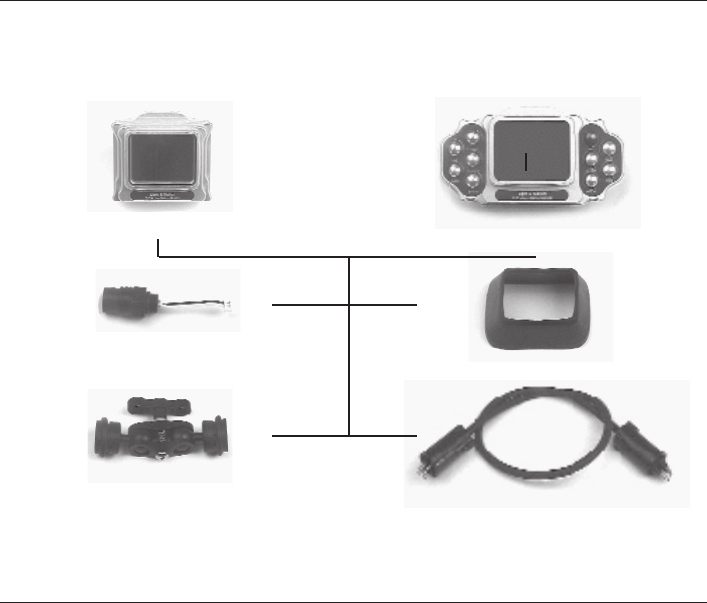
Bluefin Monitors - Getting Started
Illustrated below are the components of the Compact Monitor and the Remote
Monitor. Take time to identify and become familiar with each part.
Compact Monitor Remote Monitor
Bulkhead
Clamp Assembly
Monitor Cable
Lens Shade
Bluefin Monitor - Bulkhead Installation
1. Remove the Rear Plate.
2. Using a flat head screwdriver or coin, remove the Port Plug (Refer Fig. 20).
3. On the inside of the Rear Plate, remove the four screws using a 3/32 Allen key and remove
circuit board (Refer Fig. 21).
4. Feed Bulk Head cable through Bulk Head port (Refer Fig. 22).
5. Insert Bulk Head into Rear Plate until it is firmly seated.
6. Tightening bulk head by turning the bulk head itself with a 3/4” wrench.
7. Attach Bulk Head Cable into the Primary Bulkhead connector on the inside of the Rear
Plate circuit board.
8. Replace circuit board and secure it to the Rear Plate using the four button head cap
screws.
17
(Fig. 20) (Fig. 21)
Button head cap screws
(Fig. 22)
Attaching the Remote or Compact Monitor
1. Attach clamp assembly to back of monitor.
2. Attach monitor/clamp assembly to quick connect post by pressing down and rotating until
black sleeve locks into position.
3. Adjust monitor by releasing clamp assembly (clockwise to tighten, counter clockwise to
loosen).
4. Cable plugs are identical at each end. Attach by aligning the pins and pressing into the
bulkhead until the black rubber seats. Turn locking sleeve clockwise to tighten.
Compact Monitor Operation
Power On/Off
The monitor will power on and off with the camcorder.
Bulkhead Port

18
Remote Monitor Operation
1. If necessary, provide power to the monitor by positioning the appropriate bulkhead switch,
to the ON position. The switch is located on the inside of the Rear Plate.
2. Connect monitor cable to Bulkhead prior to entering the water.
3. Connect monitor cable to Remote Monitor prior to entering the water.
4. Station the BlueFin housing in the area you are going to shoot.
5. Gently let out the slack in the cable as you move the viewing location.
6. Operation of Controls:
Left Side (Refer Fig. 18)
L. Light - Operates left video light.
R. Light - Operates right video light.
Bright - Adjust brightness of monitor.
Far - Moves focus point further from camcorder.
Close - Moves focus point closer to camcorder.
Right Side (Refer Fig. 19)
Af/Off
AF - Press once to return camcorder to auto focus from manual focus.
OFF - Turns camcorder off. Press and hold for three seconds then release.
Rec - Toggles between record and stand-by modes.
Mom.Af - Pressing and holding this button puts the camcorder into “Momentary
AF”. Camcorder remains in AF as long as the button is pressed. Once
released, the camcorder switches to manual focus. This is useful in stopping the
camcorder from “seeking” when shooting in a low contrast environment. To
return the camcorder to AF, press the AF/OFF button.
Tele- Zooms camera to telephoto.
Wide - Zooms camera to wide angle.
Power On/Off with Remote Monitor
On - When camcorder is in a powered down state, press any button on the Remote
Monitor EXCEPT BRIGHT to return camcorder to powered up state and
activate the Remote Monitor LCD screen.
Off - Press and hold AF / OFF button for three seconds.
19
Charging the Remote and Compact Monitor
1. Remove the Charging Port Plug using a coin or large flat head screwdriver
(Refer Fig. 23).
2. Plug charger into a 110v outlet.
This charger is only rated at this voltage. If you do not have
access to a 110v outlet, you must use a converter.
3. Plug charging connector from charger into charging port on Remote Monitor.
4. Charge for 8-14 hours, then remove charging cord.
5. Check O-ring on Charging Port Plug.
6. Replace Charging Port Plug.
IMPORTANT: Failure to re-install Charging Port Plug WILL flood the Monitor.
Diving Without a Monitor Attached
If you do not use the monitor you MUST de-activate power to the bulkhead before entering
the water.
To de-activate BlueFin bulkhead:
1. Remove the Rear Plate.
2. Locate the power switch on the inside of the Rear Plate.
3. Move the switch to the OFF position.
(Fig. 23) (Fig. 24)
Charging Plug
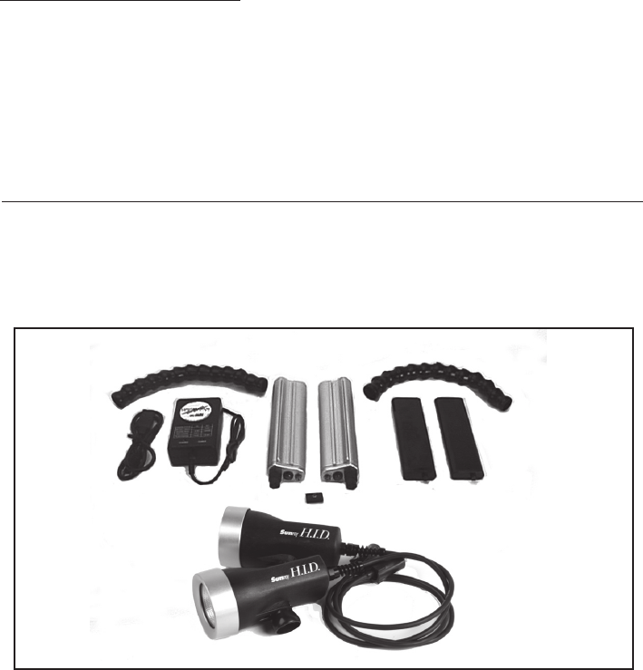
Bluefin Light Systems - Getting Started
Pictured below are the components of the Sunray Pro, Sunray-S Mini Pro and Sunray-S
Mini Elite lighting system. Take a moment to familiarize yourself with each part for later
identification and use.
Display Icons on Monitors
Monitor Screen: In order to see the camera display information in the monitor
screen, you will need to set the camera to V-OUT/PANEL on the menu screen.
Go to menu, scroll to STANDARD SET, highlight DISPLAY and set to V-OUT/
PANEL (See Fig 24 on previous page). Refer to your Sony instruction manual. If
done correctly, the external monitor will now display all of the camcorder
viewfinder information.
HID light heads
Li-ion Batteries
Sunray Pro Light System Battery Pods
Pod Locker
Charger and
electrical cord
20
Light Arms
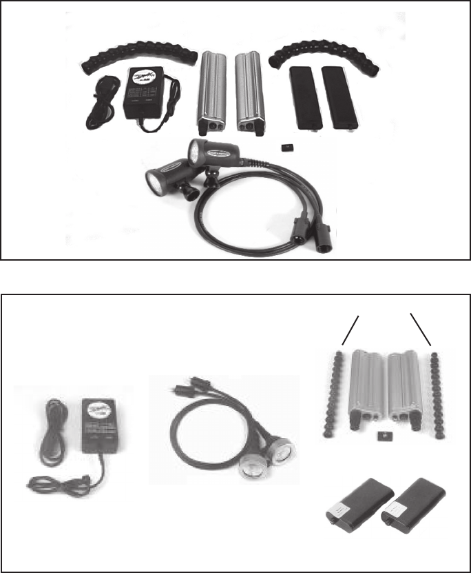
21
Battery Pods
Light heads
Charger and
electrical cord
Pod Locker
Light Arms
NiMH Batteries
Sunray-S Mini Pro Light System
Sunray-S Mini Elite Light System
Battery Pods
Charger and
electrical cord Pod Locker
Li-ion Batteries
HID light heads
Light Arms
Charging Batteries
It is recommended that you charge your batteries when they are received. It is also
recommended to charge batteries just prior to use.
1. The charger can accept an electrical range of 100 - 240v and 50 - 60hz.
2. The charger has two LED lights:
Left LED: Green when charging NiMH batteries.
Right LED: Orange when fast charging.
Green during top-up charge and when charge is complete.
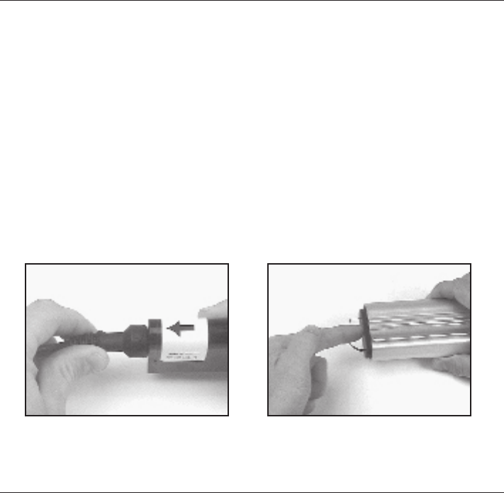
3. To attach charger to battery, align arrow on charger connector with arrow on battery label
and push together until connectors seat (Refer Fig. 25).
Note: The fast charger time is approximately 2.5 hours.
(Fig. 25) (Fig. 26)
Installing Batteries
1. Slide the battery back into the pod with the contact end inserted first so that the
connector will align with the socket inside the pod (Refer Fig. 26).
2. Inspect the O-ring on the pod cap. (See O-ring maintenance).
3. Replace the front cap onto the pod.
Note: Insure that the removal strap attached to the battery does
not interfere with the seal when the end cap is attached to the pod.
4. Turn the knob on the end cap clockwise 1/8 turn until it stops. The end cap will now be
locked into place. The end caps are specific to the left and right pods.
22

Removing Batteries
1. Rotate latch at the front of the pod counter-clockwise 1/8 turn, until it stops.
2. Pull the front cap off the pod.
3. Pull the battery from the pod using removal strap.
Mounting Battery Pods
1. Remove the rear plate of the housing.
2. Slide the battery pods into housing channels.
3. Insert Pod Locker between the pods and tighten using 1/8” Allen key.
Do not over-tighten.
Connecting Lights to Battery Pods
1. Plug in the cable connectors on the pod.
2. Tighten the locking sleeves by rotating clockwise until tight.
3. Plug in the cable connectors on the Light Head. (Pro Lights only)
4. Tighten the locking sleeves by rotating clockwise until tight.
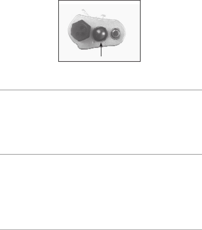
Light Operation
Confirm that the mode selector (flat position of bezel around power button) is set to the P
setting for Pro or Mini Pro Lights or E for Mini Elite Lights (Refer Fig 27).
Operation from Smart Grips
1. Activate initial power-up by pressing the Pod Power Button (Refer Fig 27).
After initial power-up lights may be controlled using LIGHT button on the left Smart Grip.
2. Turn off lights by pressing and holding the LIGHT button.
Operation from Battery Pods
1. Turn on light by pressing the Power Button on the rear cap.
2. Turn off light by pressing and holding the Power Button on the rear cap.
23
(Fig. 27)
Power Button
24
Pre-Dive Checklist
1. Make sure you have a Mini DV tape in the camcorder.
2. Make sure you have a completely charged battery in the camera.
3. Verify operation of all housing controls.
4. Check that the lens lock is securely engaged and that the latch pin is in the locked position.
Clean lens if necessary.
5. Check that the rear plate O-rings are seated correctly and that the rear latches are in the
closed and locked position.
First Time Use
All Light & Motion equipment is pressure tested prior to shipping. However, there could be
unseen damage due to shipping. A test dive without the camcorder in the housing is highly
recommended. After the initial dive with just the housing, make the following checks:
1. Dry off housing exterior.
2. Remove the Rear Plate and visually inspect for moisture.
3. Reach inside the housing and trace a finger around all view ports and mating surfaces.
4. If any water is detected, contact the housing reseller or the Light & Motion service
department.
After Diving Care
1. Immediately submerge the housing in fresh water. While in fresh water, work all the
switches and press all the buttons to work any remaining salt water out of recessed areas.
2. Remove housing from the rinse tank and towel dry.
(Fig. 28) (Fig. 29)
Housing Storage
Store housing and Travel Case in a dry location the first 24 hours after a dive. Leave the Rear
Plate off the housing to allow for air circulation. Similarly, leave Travel Case Lid about two
inches open. Allow any residual water to evaporate from the Travel Case prior to storing the
housing.
Replacing Handle Batteries
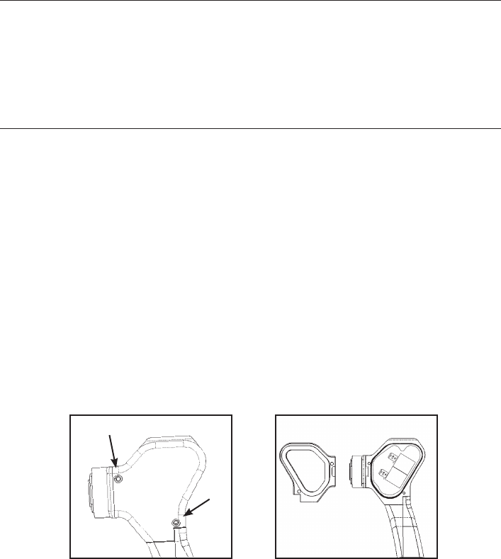
1. Using an Allen key, remove the two screws on the back of the handle. (Refer fig. 28)
2. Remove the Handle Cap from the handle assembly (Refer fig. 29).
3. Remove old batteries from handle board.
4. Install new 1/3 N batteries into the handle board (Refer. fig. 30).
Note: The +/- position of the batteries is critical. If batteries
are installed backwards, they will damage the handle board.
5. Inspect the Handle Cap O-ring or replace with a new O-ring.
6. Press the Handle Cap into the handle assembly so O-ring seals evenly.
7. Replace both screws in Handle Cap and tighten using Allen key.
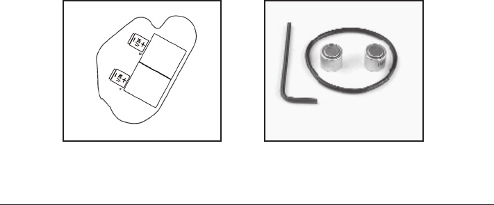
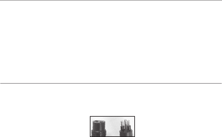
Smart Grip O-ring and Battery Kit—Part # 802-0117 (Refer fig. 31)
Kit contains one O-ring and battery set for one Smart Grip.
25
26
O-ring Care & Maintenance
O-rings are the critical component that keeps water out of the housing. Routinely
inspect O-rings and replace at least once a year. If your O-rings are damaged, contact
the Light & Motion service department for an O-ring replacement kit.
Follow these steps for proper O-ring function.
1. The sealing system used on the rear plate incorporates two O-rings. This is the most
critical area of the housing for maintenance and should be inspected before every dive.
2. Make sure the rear plate O-rings and the mating surface on the inside of the main
housing are free of grit, hair, lint and anything that could breach the O-ring seal.
3. After frequent diving or if O-rings appear dirty, remove O-rings and clean the grooves.
To remove O-rings, use finger pressure or the rounded edge of a plastic card to lift the
O-ring out of the groove.
Note: Never use a metal object to remove an O-ring. It will
cause damage to the O-ring and mating surface.
4. To check O-rings for damage, place the O-ring between the index finger and thumb.
Then pull the O-ring through your fingers, feeling for any debris or wear.
5. If O-rings are dirty, it is best to replace them. Washing dirty O-rings with soap and
water is not recommended. Soap breaks down the lubricants and will compromise the
integrity of the seal.
6. Properly greased O-rings will help maintain sealing integrity and minimize O-ring
degradation. Use enough grease to lubricate the O-ring thoroughly, but not so much
that it will attract additional debris.
7. Clean the groove with a lint free swab or the folded edge of a paper towel.
8. All of the front optic ports for the housing also utilize two O-ring seals. Also check
these seals every time the optic is removed.
(Fig. 30) (Fig. 31)
27
Other Maintenance
1. Clean the Connectors - Pay special attention to the condition of the
connectors at the end of the cables. Equally important is the female receptacle in the
battery pod. These metal connectors should “shine like a new penny.”
2. Apply a light film of O-ring grease to cables and connectors to prevent pre-mature
degradation.
Note: We highly recommend a factory annual service to maintain
proper operation of your underwater video equipment.
O-ring Parts
Bluefin O-ring Replacement Kit part # 802-0096 includes:
Two O-rings for the Rear Plate and two O-rings for front optic.
Smart Grip O-ring and Battery Kit part # 802-0117 includes:
O-ring and battery for one Smart Grip.
Note: O-rings used for the Rear Plate and all optics are different sizes.
Be sure to replace the appropriate O-ring in its respective groove.

Returning Products for Care
We highly recommend an annual factory service to maintain the proper operation of your
Bluefin Housing.
1. Before returning your Light & Motion product for care, please call or email our
service department for a RMA number.
2. Ship your product pre-paid freight with the return number printed on the outside of
the box. It is recommended that you keep your shipper’s tracking number until the
product is returned to you.
Warning: Do not ship your camera inside the housing. Shipping companies
may drop your system from up to three feet which could damage your camera.
Contact Light and Motion
Sales Department:
(831) 645-1525 • Fax (831) 375-2517
Service Department:
(831) 645-1572 • Fax (831) 375-2517
Mail:
Light & Motion
300 Cannery Row
Monterey, CA 93940
E-mail:
support@lightandmotion.com
World Wide Web:
www.uwimaging.com
FEP Ltd.
Attn: Steve Mawle
Aston House
Heimdon Rd.
Sulgrave
OX17-2SQ
England
01295 768444 (office)
07917 320370 (mobile)
01295 768446 (fax)
info@fep.co.uk
www.fep.co.uk
European Service Center
28

Bluefin Accessories
Bluefin Two-Year Fault Free Warranty . . . . . . . . . . . . 905-0201
Bluefin HD Super-Wide Angle Lens . . . . . . . . . . . . . . . 802-0201
Bluefin Super Macro Lens . . . . . . . . . . . . . . . . . . . . . . . 802-0095
Bluefin Tripod Mount . . . . . . . . . . . . . . . . . . . . . . . . . . 802-0152
Bluefin Pole Cam Mounting Kit. . . . . . . . . . . . . . . . . . . 802-0148
Bluefin Custom Travel Case . . . . . . . . . . . . . . . . . . . . . 775-0010
Bluefin Housing O-ring Kit . . . . . . . . . . . . . . . . . . . . . . 802-0096
Smart Grip Battery and O-ring Replacement Kit. . . . . 802-0117
Bluefin Handle Thread Ring Replacement Kit . . . . . . . 802-0147
Light & Motion Lanyard. . . . . . . . . . . . . . . . . . . . . . . . . 802-0167
Replacement Monitor Shade . . . . . . . . . . . . . . . . . . . . . 661-0336
Sunray-S 7.2v NiMH battery . . . . . . . . . . . . . . . . . . . . . 800-0086
Sunray-S 10.8 NiMH battery. . . . . . . . . . . . . . . . . . . . . 800-0082
Sunray 110/220v Multi-Chem Charger. . . . . . . . . . . . . 800-0124
20w Halogen Lamp (Mini Elite Light System) . . . . . . . . 824-0026
Mini Elite Light System O-ring Kit . . . . . . . . . . . . . . . . 800-0087
29

300 Cannery Row • Monterey, CA 93940
(831) 645-1525 • Fax (831) 375-2517
www.uwimaging.com
905-0271-A
