Lightcomm Technology AVXMTG10U Roof Mount Monitor with DVD User Manual F101 IM V1 0
Lightcomm Technology Co., Ltd. Roof Mount Monitor with DVD F101 IM V1 0
User Manual
Instruction Manual

1
1
2
5
7
11
15
TABLE OF CONTENTS
An LCD panel and/or video monitor may be installed in a motor vehicle and visible to the
driver if the LCD panel or video monitor is used for vehicle information , system control ,
rear or side observation or navigation . if the LCD panel or video monitor is used for
television reception , video or DVD play , the LCD panel or video monitor must be
installed so that these features will only function when the vehicle is in “park” or when
the vehicles parking brake is applied .
An LCD panel and/or video monitor used for television reception , video or DVD play
that operates when the vehicle is in gear or when the parking brake is not applied must
be installed to the rear of the driver seat where it will not be visible , directly or indirectly ,
to the operator of the motor vehicle .
Do not use any solvents or cleaning materials when cleaning the video monitor.
Do not use any abrasive cleaners , they may scratch the screen.
Use only lightly dampened lint free cloth to wipe the screen if it is dirty.
Lock the LCD screen in fully closed position when not in use.
Before putting on headphones always adjust the volume setting to off or lowest
position
Remember to leave the dome light switch in the off or auto positions when the vehicle
is unattended , as the dome lights , if left on , can drain the vehicle battery
Do not put pressure on the screen .
Caution children to avoid touching or scratching the screen , as it may become dirty or
damaged .
For safety reasons , when changing video media it is recommended that the vehicle is
not in motion , and that you do not allow children to unfasten seat-belts to change video
media or make any adjustments to the system . System adjustments can be
accomplished using the remote control , while seat-belts remain fastened .
Important Notice
Warnings
Safety precaution
* When connecting power and ground in a mobile video installation , insure that ACC
wire is fused at the point where it is connected to the vehicle ACC wiring. Failure to
do so can result in damage to the vehicle if a short circuit develops between the
vehicle connection point and the mobile video product .
Important Notice
Front view
Function descriptions
Settings and adjustments
Source feature
Installation Guide
32
10 ” TFT LCD (TFT) monitor
Built-in DVD Player
Selectable(M1 and M2) IR Receive and Transmit Codes
Multi-Lingual OSD (On Screen Display) for Control of Picture Quality and Functions
Audio\Video Source Inputs
Dome Lights with Built-in Three Way Switch
Last Memory for DVD
Built-in 16 Channel Frequency Wireless FM Modulator
EARphone Jack
Screen Mode Selection(16:9 , 4:3)
Backlit Controls
Day\Night Picture Modes
AV\Output
USB/SD support
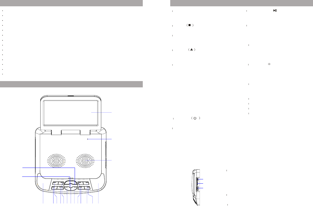
CONTROLS AND INDICATORS DIAGRAM (FRONT VIEW)
FEATURES
1 Dome Lights
Provide additional interior
illumination .
2 STOP
This button is used to stop playback.
3 SCREEN MODE
Wide (16:9) , Normal (4:3 )and
display off
4 EJECT Button
This Button is used for ejecting
discs from the disc compartment .
5 FMM
Used to select the frequentcy in
sequence rotaion : FM OFF,
CH 1 88.1MHz, CH2 88.3MHz,
CH 3 88.5MHz, CH4 88.7MHz,
CH 5 88.9MHz, CH6 89.1MHz,
CH 7 89.3MHz, CH8 89.5 MHz
CH 9 89.7MHz, CH10 89.9MHz,
CH11 90.1MHz, CH12 90.3MHz,
CH13 90.5MHz, CH14 90.7MHz,
CH15 90.9MHz, CH16 91.1MHz,
6 POWER
Used to turn the system on/off.
7 PRESS
Press this button to TFT LCD
open monitor. After the unit has
been turned on and is displaying
a picture, adjust the viewing angle,
by pivoting the screen to optimize
the picture quality.
8 PLAY\PAUSE( )
This button is used to start playback and
pause to disc.
9 VOLUME(-)
To decrease the volume of wired
headphones and decrease the level of
selected picture controls
10 PIC
Allows the user to enter the picture
adjustment mode
11 VOLUME( )
To increase the volume of wired
headphones and decrease the level of
selected picture controls
12 SOURCE
Use to select one of the sources:
DVD VIDEO1,VIDEO2, MEDIA.
13 Ventilation Openings
14 LCD cut off switch
15 LCD Panel
16 Wireless Headphones Transmit .
17: Remote control window
CONTROLS AND INDICATORS DIAGRAM (FRONT VIEW)
1 Three Position Dome Light Switch
ON-Turn on the dome lights
OFF-The dome Lights will not turn on in this position
AUTO-Automatically switches on the dome lights in
conjunction with the vehicle interior illumination.
2 SD Card Reader
Sustain SD Card \MMC .
3 USB 2.0 INPUT FOR USB PEN DRIVE
1234567891011121
13
14
15
1
2
3
16
17
1
2
CR2025 CR2025
54
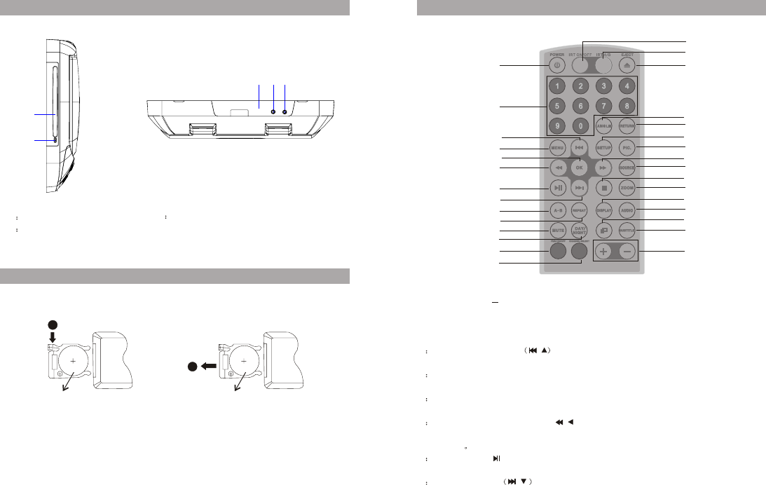
1 DISC indicator light
2 DVD Disc insertion slot
CONTROLS AND INDICATORS DIAGRAM (FRONT VIEW)
1 REMOTE CONTROL WINDOW
2. AV IN Jack
3. Headphone Jack
Remote CONTROL OPERATION
Before attempting to operate your Remote Control , install the batteries as described ibid .
Function descriptions
1
2
4
6
3
5
7
8
9
10
11
12
13
14
15
16
17
18
19
20
21
22
23
24
25
26
27
28
29
1: POWER Button press this button to turn the unit ON and OFF
2:NUMBER Button
Allow the user to enter numbers 0to 9 for selection of selection of CD tracks , DVD
chapters , password setting
3 PREVIOUS\CURSOR
GO the previous chapter or track . cursor use to menu selections on the screen.
4 MENU Button
Allows the user to access the DVD(DVD MODE)
5 OK Button(ENTER)
Used to implement a selected setting or menu option
6 SCAN BACKWARD\CURSOR( )
Scan backward at 2.4.8.16 or 4 times speed . cursor use to menu selections on the
screen.
7 PLAY\PAUSE( )
This button is used to start playback and pause to disc.
8 NEXT \CURSOR
GO the next chapter or track . cursor use to menu selections on the screen.
/
/
/
2
1
123
30

67
9AB
Allow user repeat the playback from point A to point B .
Once Repeat A- Mark the beginning of the section to repeat ( Set point A )
Twice Repeat AB Mark the end of the section repeat (Set point B)
3 times AB off Cancel the A-B repeat function .
10 REPEAT
Allows the user to repeat a selected title , chapter , or track .
For MP3 disc, press “repeat” to repeat playing present file; press it again to repeat
playing the folder .
11 MUTE
Press this button to mute the audio for wireless FMM and wired headphones.
12 DAY\NIGHT Mode Button
This control toggles the unit between “DAY” and “NIGHT” LCD illumination modes .
in the “DAY” mode, the LCD backlit intensity is at maximum. In”NIGHT” mode, the
LCD backlit is dimmed to a preset level that is more suitable for low light operation .
13 FMM ON\OFF
Turns the wireless FM Modulator on or off .
14 CHANNEL SELECT
Selects the wireless FM Modulator Frequency(CH1 88.1MHz, CH2 88.3MHz, CH3
88.5MHz, CH4 88.7MHz, CH5 88.9MHz, CH6 89.1MHz, CH 7 89.3MHz, CH8 89.5MHz
CH9 89.7MHz,CH10 89.9MHz,CH11 90.1MHz,CH12 90.3MHz,CH13 90.5MHz
CH14 90.7MHz,CH15 90.9MHz,CH16 91.1MHz).
15 VOLUME - /(+)
Press to decrease or increase the volume level of the picture adjustments .
16 SUBTITLE
Press to display and select the available subtitle language in DVD mode .
17 Screen Mode Selection( )
Press the button to screen 16:9 or 4:3 mode .
18 AUDIO
Press the button to audio language selection (depend on discs) .
19 DISPLAY
Press to display current disc information while the disc is playing .
20 ZOOM
Press this button to enlarge the picture when playing a DVD disc .
Once Enlarge the picture 1 times of the original size
Twice Enlarge the picture 2 times of the original size
3 times Enlarge the picture 3 times of the original size
4 times Enlarge the picture 4 times of the original size
5 times Picture is returned to original size .
21 STOP
Press to stop playback .
22 SOURCE
Each time the button is pressed, the audio\video source will change in the menu
selection . (DVD \AV1\CARD\USB)
24 PIC
Allows the user to enter the picture adjustment mode (BRIGHTNESS,
CONTRAST, Hue, Saturtation RESET). Once the desired adjustment bar is displayed,
use the VOLUME(+)\VOLUME(-) button to adjust the setting .the display will
automatically turn off if on adjustments are made within 6 seconds , or is any other
button is pressed .
25 SETUP
Press to display the setup menu which allows the user to change the DVD player
options such as OSD LANGUAGE, PARENTAL CONTROL etc .
26 RETURN
Press Return once : Go to disc menu .
Press Return Twice : Go to movies playback
27 ANGLE
To display multi angle picture (depend on discs)
28 EJECT
This is used to eject the disc.
29 IRT A-B
Press to change IRT transmit band between A&B.
30 IRT ON/OFF
23 SCAN FORWARD( )
Scan Forward at 2.4.8.16 or 4 times speed . cursor use to menu selections on the
screen.
Turns the IRT on or off .
Function descriptions Function descriptions
SETTINGS AND ADJUSTMENTS
The setup Menu contains features and options that let you customize your DVD player .
For example , you can set a language for the on screen display, limit playback for
children
/
89
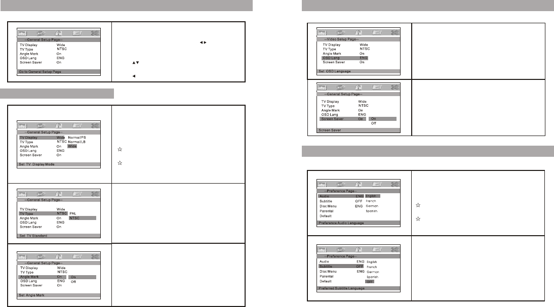
SYSTEM SETUP
Press “Setup” button, the main menu will be
displayed on the screen.
In the General Setup Page, press button to
highlight this item.
Press OK button to access.
Press button to select the settings.
Press OK button to confirm your selection.
Press button to exit.
GENERAL SETUP PAGE
TV Display
Enter this option, user can set screen display
format(Normal/PS, Normal/LB, Wide)
The default is “Wide”
Note
The function depends on the display ratio
with which the DVD disc is recorded.
Please choose “Wide(16:9) when using 16:9
wide screen TV set 16:9.
TV Type
Enter this option to select TV type(PAL, NTSC)
The default is NTSC.
Angle Mark
Enter this option to set the angle during playback.
Optional setting: ON, OFF
The default is PAL
SYSTEM SETUP
OSD Language
In this option, user can set OSD menu language.
The default is English.
Screen Saver
Enter this option to set whether to activate the
screen saver function.
The default is ON.
SYSTEM SETUP
Audio
Enter this option, user can select your preferred
audio language for DVDs. The default is English.
Note
User can also change the audio language during
playback by pressing the Audio button.
The audio language depends on the material
on each disc.
Subtitles
Select your preferred language to show the
subtitles on the screen. The subtitle languages
depend on the information available on each disc.
You can also change the subtitle language during
playback by pressing the Subtitle button.
10 11
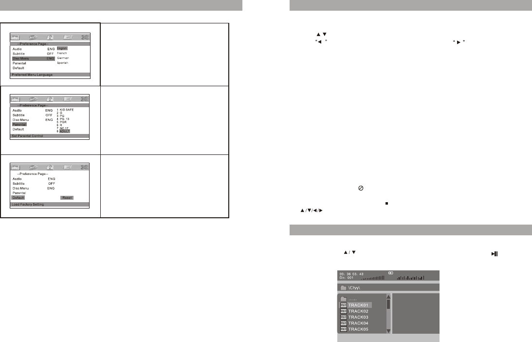
SYSTEM SETUP
Disc Menu
This function allows you to choose the menu
language stored on the disc.
The default is English.
The function is only available for DVD.
Parental
Enter this option, user can set child lock to prevent
children watching some unsuitable content in DVD
disc.
The function is disc-dependent.
The default is ADULT.
Default
Select this item and press OK button to reset all
settings to the original factory settings.
PLAYING JPG FILES
1. Place a JPG disc into the tray, the unit will start reading and play.
2. Press MENU to browse JPG files.
3. Press" " to select a JPG file and press OK button to confirm.
4. Press to rotate the picture counter-clockwise, press to rotate the picture
clockwise.
5. Press DISPLAY when viewing pictures, you can select different refresh mode as
follows:
a. from top to bottom
b. from bottom to top
c. from left side to right side
d. from right side to left side
e. from left top to right bottom
f. from right top to left bottom
g. from left bottom to right top
h. from right bottom to let top
i. from horizontal center to both sides
j. from vertical center to both sides
k. from top and bottom to center
l. From right and left to center
m. from four window's top side to bottom side
n. from four window's left side to right side
o. from 4 edges to center
6. During viewing files, “ ” may appear when pressing “Angle” or “Subtitle” or “Audio”
or “Title” etc, in this situation, these options are unavailable to operate.
7. When viewing JPG files, press “ ” , pictures will be displayed in thumbnail mode, press
“ ”or “ OK ”button to select one picture to view.
PLAYING MP3 FILES
1. Place MP3 disc into the disc door or insert USB disk, SD card to USB port or SD
card slot, press “ ” or “ OK ” button to choose a MP3 file, press “ ” or “ OK ”
button to play the file selected.
12 13
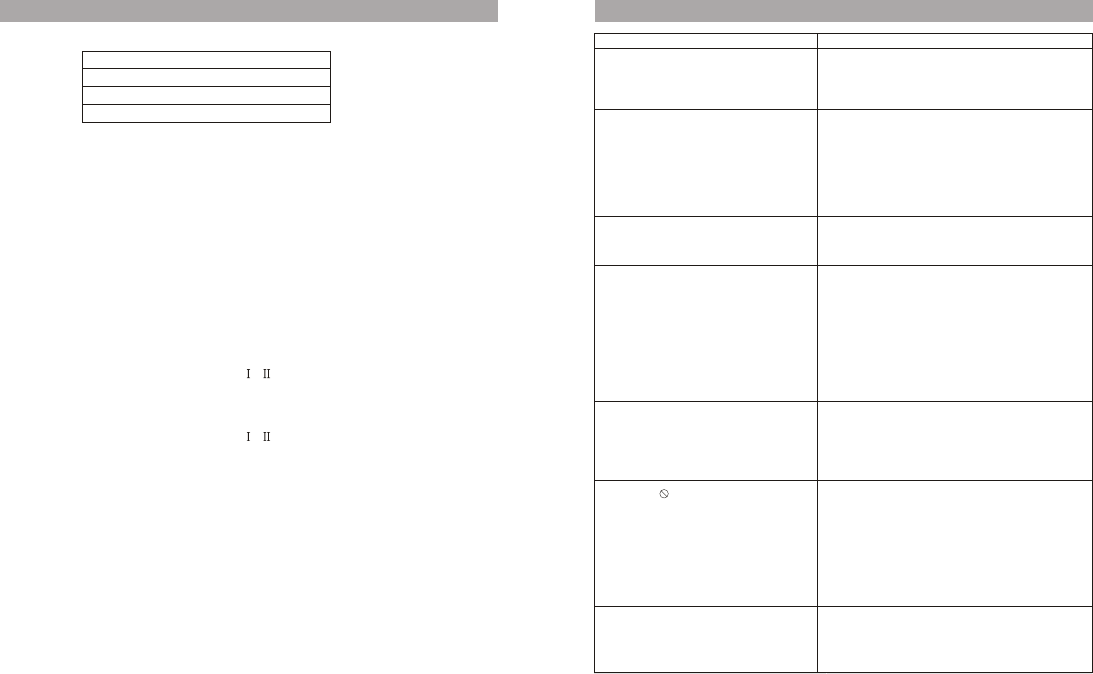
TROUBLE SHOOTING
PROBLEM SOLUTION
IR remote inoperative
Disc won’t play
Play starts, but then stop immediately
No sound or distorted sound
Can’t advance through a movie
The icon ( ) appears on screen
Picture is distorted
1. Verify that the batteries in the remote are
fresh.
2. Verify that the remote sensor eye is not
obstructed.
1. The disc might be damaged, try another
disc.
2. It is normal for some distortion to appear
during forward or reverse scan.
The feature or action cannot be completed at
this time because
1. The disc’s software restricts it.
2. The disc’s software doesn’t support the
feature.
3. The feature is not available at the moment.
4. You’ve requested a title or chapter number
that is out of the range.
1. You can’t advance through the opening
credits and warning information that
appears at the beginning of a movie
because the disc is programmed to
prohibit that action.
1. Make sure your DVD is connected properly.
Make sure all cables are securely inserted
into the appropriate jacks.
2. If you are using 2-channel IR headphones,
make sure you turn on the IR headphone
power, make sure the correct channel(A-B)
is selected.
3. Make sure the modulator is ON and the
proper frequency has been selected.
1. The disc is dirty, clean it.
2. Condensation has formed, allow player to
dry out.
1. Insert a disc with the label side facing up.
2. Check the type of the disc you put into the
disc tray. This DVD only plays DVD, VCD,
audio CD, JPEG, MP3 and MPEG4.
3. Both the unit and the disc are coded by
region. If the regional code doesn’t match,
the disc can’t be played.
SOURCE FEATURE
DVD
When a disc is loading to the DVD player, the program system will switch to DVD mode
directly whatever the CARD or USB and AV is in play condition.
Last Memory for the DVD mode: Every time turning power on, it will play from the point
stopped last time.
At power OFF mode, put into a disc, and it can automatically slot in the disc and turn
power on.
AV1
The unit will accept an audio/video input through the 3RCA jacks located on the rear of
the unit. The audio/video device can be a video game system, video camera, or other
input device.
CARD
Insert a card(compatible with normal SD/MMC/MS) and play content.
Supported format: MP3, JPEG, AVI, MPEG , etc.
USB
Insert USB and play content.
Supported format: MP3, JPEG, AVI, MPEG , etc.
OVERHEAD DOME LIGHTS
The Dome Light integrated into the F101 are controlled by a three position slide switch.
Sliding the switch to the ON position will turn the light ON. The OFF position will
prevent the lights from turning ON with the vehicle interior lighting, and the auto
position will allow the lights to turn ON and OFF with the vehicle interior lighting. Refer
to the installation guide for wire connections. Do not leave the vehicle unattended with
the dome light switch in the ON position, as this could result in a discharged battery.
REMOTE SENSOR
The unit incorporates two infrared remote sensors which relay signals from the remote
control to allow the unit to be controlled simply by pointing its remote control at the
remote sensor. The infrared sensor can relay signals from most manufacturer's remote
control to its respective component connected to the AV input, in this case, you must
use the remote control supplied with the component.
DVD
AV1
USB
SD

14
Type : TFT Active Matrix LCD
Pixels :800x480
Operation Temperature : 0 ~ 55°C
Storage Temperature : -20 ~ 70°C
Back light : LED
Power Source : DC12V
Video Display System : NTSC/PAL
Headphone Audio Output : 0.05W @ 32 ohms
Video Output : 1.0Vpp@ 75 ohms
SPECIFICATIONS
FCC STATEMENT
1. This device complies with Part 15 of the FCC Rules.
Operation is subject to the following two conditions:
(1) This device may not cause harmful interference, and
(2) This device must accept any interference received, including interference
that may cause undesired operation.
2. Changes or modifications not expressly approved by the party responsible for
compliance could void the user's authority to operate the equipment.
NOTE: This equipment has been tested and found to comply with the limits for a
Class B digital device, pursuant to Part 15 of the FCC Rules. These limits are
designed to provide reasonable protection against harmful interference in a
residential installation. This equipment generates, uses and can radiate radio
frequency energy and, if not installed and used in accordance with the
instructions, may cause harmful interference to radio communications. However,
there is no guarantee that interference will not occur in a particular installation.
If this equipment does cause harmful interference to radio or television reception,
which can be determined by turning the equipment off and on, the user is
encouraged to try to correct the interference by one or more of the following
measures:
-- Reorient or relocate the receiving antenna.
-- Increase the separation between the equipment and receiver.
-- Connect the equipment into an outlet on a circuit different
from that to which the receiver is connected.
-- Consult the dealer or an experienced radio/TV technician for help.
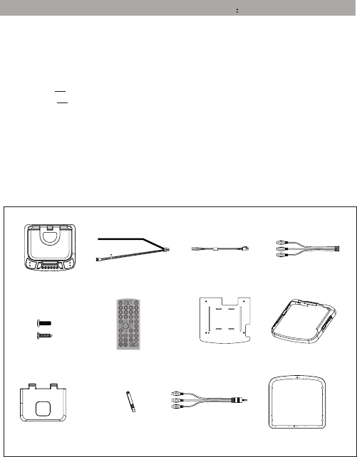
Installation Guide
1) 10” LCD Overhead Monitor with DVD play-(1 PCS)
2) 6 Pin Power harness ( 1 PCS )
3) 2 Pin Power / Wire Harness with choke ( 1 PCS )
4) 3 RCA jack pigtail ( 1 PCS)
5) hardware package
# M5*9 4PCS
# TA4*9 6PCS
6) Remote Control ( 1 PCS)
7) Mounting Bracket (1 PCS)
8)Snap on cover 3pcs
9)Snap on cover 3pcs
10)Pry Tool
11)3.5mm TIP/3RCA JACK PIG TAIL (1PC)
12) 3pcs
MATERIALS INCLUDED IN THIS PACKAGE
123
4
57
6
15
8
91011 12
1)Decide upon system configuration and options that will be installed.
2)Review all manuals to become familiar with electrical requirements and hook ups
3)Decide upon mounting location of all components and method of mounting
4)Prep the vehicle by removing any interior trim necessary to gain access to vehicle’s
wiring as well as all areas wher interconnecting wire harnesses will need to be located.
If any access holes need to be cut into the vehicle, this should be done now as well .
5)Route the wiring harnesses throughout the vehicle as necessary.(Refer to the wiring
Diagrams on this manual as well as the wiring instructions for the individual
components and accessory options being installed). Be sure that all wiring is protected
from sharp edges and is routed in such a manner that pinched when all components and
interior trim are fully installed. Be sure to leave enough slack in the wiring at each
component to allow working room
6)Remove all A/V system components form their packaging and place them loosely in the
vehicle at their respective locations.
7)Connect all components together and verify proper operation of all system functions.
Note: This is best done BEFORE , components have been permanently mounted .
8)After verifying proper operation of the system , proceed to mount of each component
9)When all components are mounted , recheck function of entire system again to ensure
that no wiring was pinched or connected improperly during final installation..
GENERAL INSTALLATION APPROACH
17
16
1. 2. 3.
4.
1 32
1 2
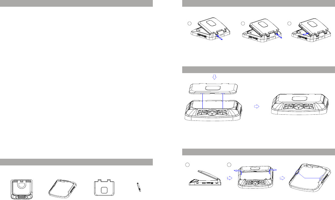
Installing the snap on covers
Place the pod on a soft
surfaces to avoid
dannaging the plastic
Shroud Screen Back Cab
Disconnect the screen cover
Inset the supplied prytoool to “A”,”B”and “c” snap on cover.
“A” “B”
“C”
Installing the screen cover
“D”
Open the screen and hook the two tabs”D”on the buttom edge of the screen snap the
opposite side over the bringe
Disconnect the shroud
Beg in by hooking area “E”(fastener) over the dome light and slide the cover over the
pod The cover will snap in place.
“E”(fastener)
“D”
“D”“D”
Pry Tool
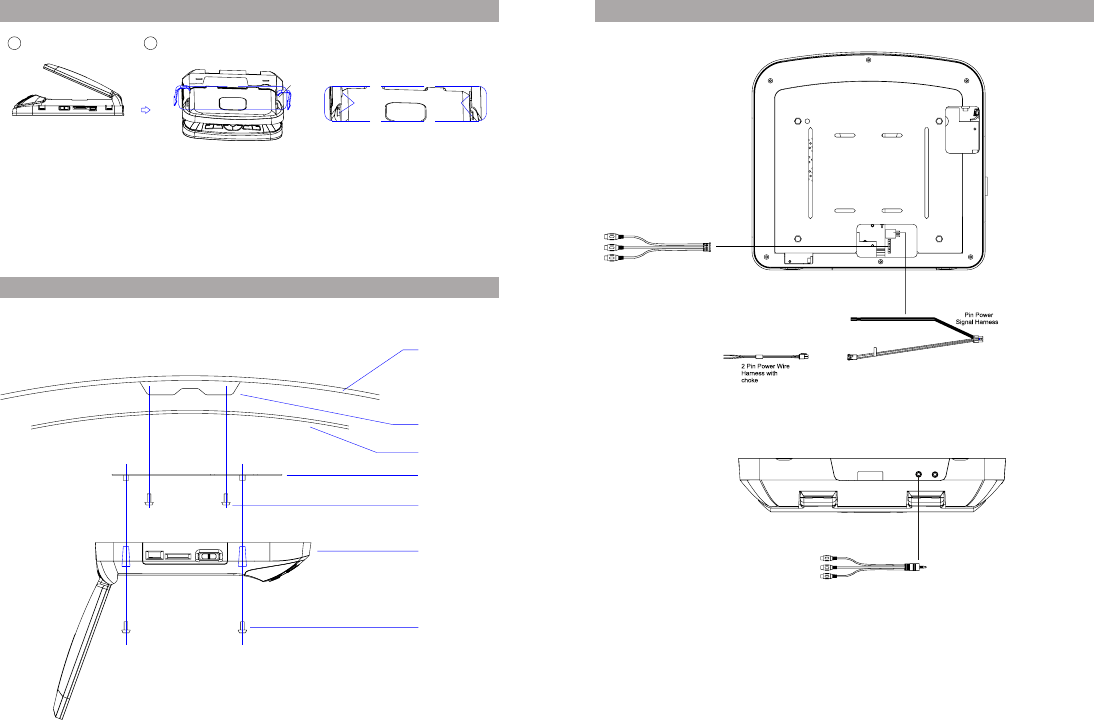
M5 Screw
Video Unit
Self-drilling Screws
Mounting Bracket
Headliner
Roof Support
Roof
GENERAL INSTALLATION APPROACH
Installing the shroud
1 2
Open the monitor angle to pull “F” fist note and contraposition “I”button up
“F”
18
GENERAL INSTALLATION APPROACH
19
6
AV IN 3RCA jack pig tail
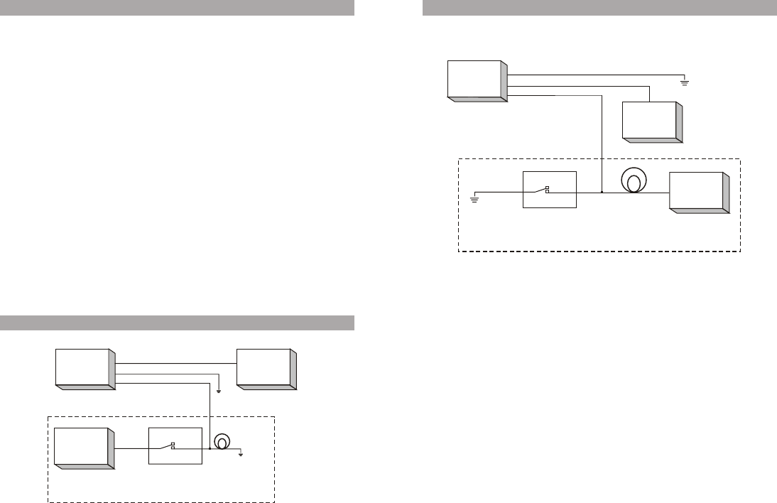
For negative systems, connect the purple / brown (Lamp auto) wire to the vehicle's
switched wire. The connect the red / black (lamp on) wire to a good ground and the black
/ red (lamp common ) wire to fused constant 12 volt source. Negative systems are
commonly found on General Motors and import vehicles.
NOTE: Some vehicles which incorporate transistorized control of the dome light circuit,
such as the 1999 Dodge Caravan, may require that the purple / brown (Lamp auto) wire
be connected to the door pin switch wire, as the additional current draw of the Monitor's
lights may not be supported by the output of the vehicles body control computer.
CONNECTING THE DOME LIGHTS
Positive Switched Dome Lighting
The dome lights in the video monitor require three connections to the vehicle's wiring
.There are two common types of dome light circuits used, positive or negative switched.
Positive systems supply voltage to the interior lights to turn them on , negative switched
systems apply ground to illuminate the bulbs. To determine which system you have you
must locate the wires at the dome light. On a positive switched system. with all the
doors closed and lights out, both wires at the dome light will rest at ground. When the
light is activated, one of these wires will switch to +12 vdc . This is vehicle's switching
wire. On a negative switched system, with all the doors closed and the lights out. Both
wires at the dome light will rest at +12vdc.When the light is activated. One of these
wires will switch to ground. This is the switching wire.
For positive systems, connect the purple / brown (Lamp auto) wire to vehicle's switched
wire. Then connect the red / black (lamp on) wire to a fused constant 12 colt source and
the black/red(lamp common) wire to a good ground. Positive systems are commonly
found on Ford vehicles.
To 6 pin
connector
on Monitor
To
constant
+12vdc
To
constant
+12vdc
Factory Door ajar
switch or Body
Control computer
Red/black-Lamp on
Black/red-Lamp common
Purple/brown-Lamp Auto
21
20
Negative Switched Dome Lighting
To 6 pin
connector
To
constant
Factory Door ajar
switch or Body
Control computer
Red/black-Lamp on
Black/red-Lamp common
Purple/brown-Lamp Auto
To
constant