Lilee Systems TRANSAIRP3001 TRANSAIR PTC-3001 User Manual
Lilee Systems, Ltd. TRANSAIR PTC-3001 Users Manual
Contents
Users Manual
Lilee Systems™
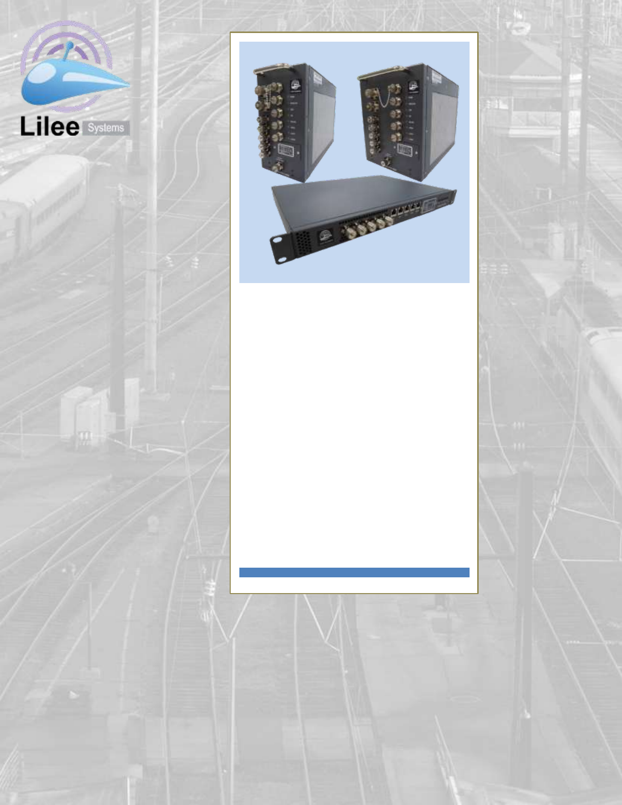
TransAir™ PTC-3000
Family
User Manual
December 5, 2012

Lilee Systems™ TransAir™ PTC-3000 Family User Manual
Page ii
Copyright and Trademark Notice
This manual and all software described herein are protected by copyright: © 2011 Lilee Systems,
Ltd. Lilee and TransAir are trademarks of Lilee Systems. All rights reserved. The information in
this document is subject to change without prior notice in order to improve reliability, design and
function and does not represent a commitment on the part of the manufacturer.
Please visit our website for the most up-to-date product information: www.lileesystems.com.

Lilee Systems™ TransAir™ PTC-3000 Family User Manual
Page iii
1 BEFORE YOU BEGIN ................................................................................................................................ 1
1.1 RF EXPOSURE COMPLIANCE REQUIREMENTS/ EXIGENCES DE CONFORMITÉ DE L'EXPOSITION RF .............. 1
1.2 SAFETY CONSIDERATIONS ................................................................................................................................... 4
1.3 ESD NOTICE .................................................................................................................................................... 4
1.4 FCC/IC APPROVAL NOTICE/ AVIS D'APPROBATION FCC/IC ...................................................................................... 4
1.5 FCC PART 15 NOTICE/IC RSS-210_GEN AVIS ..................................................................................................... 4
1.6 EQUIPMENT MODIFICATIONS/MODIFICATIONS APPORTÉES À L'ÉQUIPEMENT ................................................................ 5
1.7 RADIATED POWER LIMITS/LIMITES DE PUISSANCE RAYONNÉES ................................................................................... 5
1.8 ANTENNA GUIDELINES/ LES LIGNES DIRECTRICES D'ANTENNE ...................................................................................... 6
1.9 PACKAGE CHECKLIST .......................................................................................................................................... 8
1.10 OPTIONAL STARTER KIT ...................................................................................................................................... 9
2 INTRODUCTION ....................................................................................................................................... 10
2.1 FEATURES ...................................................................................................................................................... 10
3 INTERFACE PANEL CONNECTORS .................................................................................................... 11
3.1 1PPS IN/OUT ................................................................................................................................................. 13
3.2 12 V DC POWER ............................................................................................................................................ 13
3.3 220 MHZ ANTENNA ....................................................................................................................................... 14
3.4 3G ANTENNA ................................................................................................................................................. 14
3.5 GPS ANTENNA ............................................................................................................................................... 14
3.6 LAN ............................................................................................................................................................. 15
3.7 RS-232 CONSOLE ........................................................................................................................................... 15
3.8 RS-232/422/485 SERIAL ............................................................................................................................... 16
3.9 WI-FI ANTENNA ............................................................................................................................................. 16
3.10 LED INDICATORS............................................................................................................................................. 17
3.11 PTC-3000 RF (220MHZ RF BOARD) ................................................................................................................ 18
4 INSTALLATION ........................................................................................................................................ 19
4.1 CONNECTING CABLES ....................................................................................................................................... 19
4.1.1 RJ45 to DB9 Console Cable (PTC-3000-1U) ............................................................................................ 19
4.1.2 M12 to DB9 Console Cable (PTC-3201~4, PTC-3004, and PTC-3006 (M12)) .......................................... 19
4.1.3 RJ45 LAN Cable (PTC-30001) .................................................................................................................. 20
4.1.4 M12 to RJ45 LAN Cable (PTC-30001) ..................................................................................................... 20
4.1.5 RJ45 to DB9 Serial Device Cable (PTC-30001) ........................................................................................ 20
4.1.6 M12 to DB9 Serial Device Cable (PTC-3201~4, PTC-3004, and PTC-3006) ............................................. 21
4.1.7 TNC to SMA Male Connector for Wi-Fi Antennas with SMA Connectors ............................................... 21
4.1.8 TNC to SMA Female Connector for GPS or 3G........................................................................................ 21
4.1.9 TNC to TNC Cable for Syncing PTC-3000 Units ....................................................................................... 22
4.1.10 Power Cable and Power Adapter ....................................................................................................... 22
4.2 USB FLASH DISK REMOVAL AND INSTALLATION .................................................................................................... 22
4.2.1 Remove SIM/USB/Reset Panel Cover ..................................................................................................... 22
4.2.2 USB Flash Drive Removal ....................................................................................................................... 23
4.2.3 USB Flash Drive Installation ................................................................................................................... 24
4.2.4 Replace SIM/USB/Reset Panel Cover ..................................................................................................... 25
4.3 SIM CARD INSTALLATION ................................................................................................................................. 25

Lilee Systems™ TransAir™ PTC-3000 Family User Manual
Page iv
5 CONFIGURING THE PTC-3000 .............................................................................................................. 27
5.1 CONFIGURATION COMMANDS ........................................................................................................................... 27

Lilee Systems™ TransAir™ PTC-3000 Family User Manual
Page v
FIGURE 3-1 – PTC-3000-1U INTERFACE PANEL CONNECTOR LOCATIONS (FRONT AND REAR) WITH
SIM/USB/RESET PANEL COVER REMOVED ....................................................................................................... 11
FIGURE 3-2 – PTC-3004 INTERFACE PANEL CONNECTOR LOCATIONS (PTC-3006 AND PTC-3201~4 WILL HAVE
SAME OR LESS PORTS AND WITH SIMILAR FUNCTIONALITIES) ............................................................................ 12
FIGURE 3-3 – SIM CARD SLOT, USB FLASH DISK, AND RESET BUTTON LOCATIONS ............................................. 12
FIGURE 3-4 – LED INDICATORS ................................................................................................................................. 17
FIGURE 3-5 – PTC-3000 RF LABEL ........................................................................................................................... 18
FIGURE 3-5 – 220MHZ RF BOARD ............................................................................................................................. 18
FIGURE 4-1 – SIM/USB/RESET PANEL COVER ..................................................................................................................... 23
FIGURE 4-2 – USB FLASH DRIVE REMOVAL (1U UNIT SHOWN) ................................................................................ 23
FIGURE 4-3 – USB PORT LOCATION (1U UNIT SHOWN) ......................................................................................................... 24
FIGURE 4-4 – USB FLASH DRIVE INSTALLATION (1U UNIT SHOWN) ......................................................................... 24
FIGURE 4-5 – REPLACE SIM/USB/RESET PANEL COVER ........................................................................................................ 25
FIGURE 4-6 – SLIDE SIM CARD SLOT PROTECTIVE COVER DOWN .......................................................................... 25
FIGURE 5-1 – SERIAL PORT SETTINGS....................................................................................................................... 27

Lilee Systems™ TransAir™ PTC-3000 Family User Manual
Page vi
TABLE 1-1 – PACKAGE CHECKLIST .......................................................................................................................................... 8
TABLE 1-2 – OPTIONAL STARTER KIT ...................................................................................................................................... 9
TABLE 3-1 – INTERFACE PANEL CONNECTORS ........................................................................................................................ 13
TABLE 3-2 – 1PPS IN/OUT CONNECTOR PINOUTS................................................................................................................... 13
TABLE 3-3 – 12 V DC POWER CONNECTOR PINOUTS ............................................................................................................. 13
TABLE 3-4 – 220 MHZ ANTENNA CONNECTOR PINOUTS ........................................................................................................ 14
TABLE 3-5 – COAXIAL CABLE SIGNAL LOSS AT 220 MHZ ......................................................................................................... 14
TABLE 3-6 – 3G ANTENNA CONNECTOR PINOUTS ................................................................................................................. 14
TABLE 3-7 – GPS ANTENNA CONNECTOR PINOUTS ................................................................................................................ 14
TABLE 3-8 – LAN PINOUTS ............................................................................................................................................... 15
TABLE 3-9 – RJ45 CONSOLE PORT PINOUTS AND DB9 TERMINATION PINOUTS (PTC-3001) ........................................................ 15
TABLE 3-10 – M12 CONSOLE PORT PINOUTS AND DB9 TERMINATION PINOUTS (PTC-3201~4, PTC-3004, AND PTC-3006 ) ........ 15
TABLE 3-11 – RJ45 SERIAL PORT PINOUTS AND DB9 TERMINATION PINOUTS (PTC-3000-1U) .................................................... 16
TABLE 3-12 – M12 SERIAL PORT PINOUTS AND DB9 TERMINATION PINOUTS (PTC-3201~4, PTC-3004, AND PTC-3006 ) ............. 16
TABLE 3-13 – WI-FI ANTENNA CONNECTOR PINOUTS ............................................................................................................ 16
TABLE 3-14 – LED INDICATORS.......................................................................................................................................... 17
TABLE 5-1 – LED INDICATORS ............................................................................................................................................ 27

Page 1
1 Before You Begin
Carefully remove and inspect the package contents. Refer to the Package Checklist below.
Please adhere to the following Safety Considerations.
1.1 RF EXPOSURE COMPLIANCE REQUIREMENTS/ EXIGENCES
DE CONFORMITÉ DE L'EXPOSITION RF
The PTC-3000 family must be professionally installed and must ensure a minimum
separation distance listed below between the radiating structure and any person.
Note that with PTC-3000 RF Board Fixed installation with highest gain antenna of 14.1dBi,
the antenna of the product, under normal use condition, should be at 2.08 m away from the
body of any user for fixed installation.
Note that with PTC-3000 RF Board Mobile installation with highest gain antenna of 5.2dBi,
the antenna of the product, under normal use condition, should be at 1.41 m away from the
body of any user for mobile installation.
Note that PTC-3004, PTC-3200 family, PTC-3001 and PTC-3006 Fixed installation with
highest gain antenna of 14.1dBi, the antenna of the product, under normal use condition,
should be at 2.5 m away from the body of any user for fixed installation. Note that PTC-
3004 RF exposure limits apply to all PTC-3000 family.
Note that with PTC-3004, PTC-3200 family, PTC-3001 and PTC-3006 Mobile installation
with highest gain antenna of 5.2dBi, the antenna of the product, under normal use condition,
should be at 1.74 m away from the body of any user for mobile installation. Note that PTC-
3004, PTC-3200 family, PTC-3001 and PTC-3006 RF exposure limits apply to all PTC-3000
family.
The output power for fixed stations is factory set max limit at 45.5dBm on 220MHz antenna
ports. The maximum EIRP is 50.4dBm based on max gain antenna of 14.1dBi and cable
loss of 9.2dB. If user/installer exceeds this max EIRP, the installer must increase cable loss
and/or lower power accordingly. Note that output power is variable, and the actual power is
chosen at the time installation depending on cable losses, Antenna height and gain and
terrain as per FCC/ IC licensing procedures.
The output power for mobile stations is factory set max limit at 44.5dBm on 220MHz
antenna ports. The EIRP is is 46.9dBm based on max gain antenna of 5.2dBi and cable loss
of 2.8dB. If user/installer exceeds this max EIRP, the installer must increase cable loss
and/or lower power accordingly. Note that output power is variable, and the actual power is
chosen at the time installation depending on cable losses, Antenna height and gain and
terrain as per FCC/ IC licensing procedures.

Lilee Systems™ TransAir™ PTC-3000 Family User Manual
Page 2
The concentrated energy from an antenna may pose a health hazard. People should not be
in front of the antenna when the transmitter is operating. The installer of this equipment must
ensure the antenna is located or pointed such that it does not emit an RF field in excess of
Health Canada limits for the general population. Recommended safety guidelines for the
human exposure to radio frequency electromagnetic energy are contained in the Canadian
Safety Code 6 (available from Health Canada) and the Federal Communications
Commission (FCC) Bulletin 65.
Any changes or modifications not expressly approved by the party responsible for
compliance (in the country where used) could void the user's authority to operate the
equipment.
La famille PTC-3000 doit être installé par un professionnel et doit garantir une distance
minimale de séparation entre énumérés ci-dessous la structure rayonnante et toute
personne.
Notez qu'avec PTC-3000 RF Board Installation fixe avec antenne haut gain de 14.1dBi,
l'antenne du produit, dans des conditions normales d'utilisation, doit être à 2,08 m du corps
d'un utilisateur pour une installation fixe.
Notez qu'avec PTC-3000 RF Board Installation mobile avec antenne haut gain de 5.2dBi,
l'antenne du produit, dans des conditions normales d'utilisation, doit être de 1,41 m à partir
du corps d'un utilisateur pour une installation mobile.
Notez qu'avec PTC-3004, PTC-3200 family, PTC-3001 and PTC-3006 Installation fixe avec
antenne haut gain de 14.1dBi, l'antenne du produit, dans des conditions normales
d'utilisation, devrait être de 2,5 m à partir du corps d'un utilisateur pour une installation fixe.
Notez que PTC-3004, PTC-3200 family, PTC-3001 and PTC-3006 les limites d'exposition
RF s'appliquent à tous les PTC-3000 famille.
Notez qu'avec PTC-3004, PTC-3200 family, PTC-3001 and PTC-3006 Installation mobile
avec antenne haut gain de 5.2dBi, l'antenne du produit, dans des conditions normales
d'utilisation, doit être à 1,74 m à partir du corps d'un utilisateur pour une installation mobile.
Notez que PTC-3004 les limites d'exposition RF s'appliquent à tous les PTC-3000 famille.
La puissance de sortie pour les stations fixes est réglé en usine limite max à 45.5dBm sur
les ports d'antenne 220MHz. La pire maximale est basée sur 50.4dBm antenne à gain max
de 14.1dBi et la perte de câble de 9.2dB. Si l'utilisateur / installateur dépasse ce maximum
pire, l'installateur doit augmenter la perte de câble et / ou de puissance inférieure
conséquence. Notez que la puissance de sortie est variable, et la puissance réelle est choisi
au moment de l'installation en fonction de pertes dans les câbles, hauteur d'antenne et le
gain de terrain et par la FCC / IC procédures d'octroi de licences.
La puissance de sortie pour les stations mobiles est réglé en usine limite max à 44.5dBm
sur les ports d'antenne 220MHz. Le pire est 46.9dBm est basée sur l'antenne à gain max de
5.2dBi et la perte de câble de 2.8dB. Si l'utilisateur / installateur dépasse ce maximum pire,

Lilee Systems™ TransAir™ PTC-3000 Family User Manual
Page 3
l'installateur doit augmenter la perte de câble et / ou de puissance inférieure conséquence.
Notez que la puissance de sortie est variable, et la puissance réelle est choisi au moment
de l'installation en fonction de pertes dans les câbles, hauteur d'antenne et le gain de terrain
et par la FCC / IC procédures d'octroi de licences.
Le concentré d'énergie à partir d'une antenne peut poser un risque pour la santé.
Personnes ne doivent pas être en face de l'antenne lorsque l'émetteur est en marche.
L'installateur de cet équipement doit s'assurer que l'antenne est située ou orientée de façon
à ne pas émettre un champ RF dépassant les limite de Canada Santé pour la population
générale. Consignes de sécurité recommandées pour l'exposition humaine à l'énergie
électromagnétique de fréquence radio sont contenues dans le Code canadien de sécurité 6
(disponible auprès de Santé Canada) et la Federal Communications Commission (FCC)
Bulletin 65.
Les changements ou modifications non expressément approuvés par la partie responsable
de la conformité (dans le pays d'utilisation) peut annuler le droit de l'utilisateur à utiliser cet
équipement..

Lilee Systems™ TransAir™ PTC-3000 Family User Manual
Page 4
1.2 Safety Considerations
Please ensure the following safety precautions are adhered to at all times.
Follow electrostatic precautions whenever the PTC-3000 is installed. To prevent
malfunction or damage which may be caused by Electrostatic Discharge, the PTC-
3000 should be grounded. Before touching components or connecting/disconnecting
cables, the installer should touch a metal object to dissipate body charge.
Make sure the power is turned off and the power cord is disconnected
whenever the PTC-3000 is being installed or moved.
Do not apply voltage levels that exceed the specified voltage range. Doing so
may cause fire and/or an electrical shock.
Do not open the chassis when the PTC-3000 is running: Electric shocks can
occur.
If considerable amounts of dust, water, or fluids enter the PTC-3000, turn off the
power supply immediately, unplug the power cord, and contact the distributor or
sales representative.
DO NOT do the following:
o DO NOT drop the PTC-3000 onto a hard surface.
o DO NOT use the PTC-3000 in a site where the ambient temperature exceeds
the rated temperature.
1.3 ESD Notice
To prevent malfunction or damage to this product, which may be caused by Electrostatic
Discharge (ESD), the radio should be properly grounded at the time of installation. In
addition, the installer or maintainer should follow proper ESD precautions, such as touching
a bare metal object to dissipate body charge, prior to touching components or
connecting/disconnecting cables.
1.4 FCC/IC Approval Notice/ Avis d'approbation FCC/IC
This device is offered as a licensed transmitter per FCC Parts 80, 90, & 95 and IC RSS-119.
It is approved for use under the following conditions: Changes or modifications not expressly
approved by the party responsible for compliance will void the user’s authority to operate the
equipment.
Cet appareil est un émetteur conforme à la FCC partie 80, 90, & 95 et IC RSS-119. Son
utilisation est uniquement approuvée dans les conditions suivantes: Tout changement ou
modification non expressément approuvé par la partie responsable de la conformité
entraînera le retrait du droit d’exploiter l’équipement.
1.5 FCC Part 15 Notice/IC RSS-210_GEN Avis
Operation of this device is subject to the following two conditions:
(1) This device may not cause harmful interference, and (2) this device must accept any
interference received, including interference that may cause undesired operation. Any
unauthorized modification or changes to this device without the express approval of the

Lilee Systems™ TransAir™ PTC-3000 Family User Manual
Page 5
manufacturer may void the user’s authority to operate this device. Furthermore, this device
is intended to be used only when installed in accordance with the instructions outlined in this
manual. Failure to comply with these instructions may void the user’s authority to operate
this device.
L’exploitation de cet appareil est soumis aux deux conditions suivantes:
(1) ce dispositif ne doit pas causer d'interférences nuisibles, et (2) cet appareil doit accepter
toute interférence reçue, y compris les interférences qui peuvent provoquer un
fonctionnement indésirable. Toute modification non autorisée de cet appareil sans
l'approbation expresse du fabricant peut provoquer le retrait de l’autorisation d’exploiter cet
appareil. De plus, ce dispositif est destiné à être utilisé uniquement lorsqu'il est installé
conformément aux instructions décrites dans ce manuel. Toute infraction à ces instructions
peut engendrer le retrait de l’autorisation d’exploiter l’appareil.
1.6 Equipment Modifications/Modifications apportées à
l'équipement
Caution: Any changes or modifications to this equipment not expressly approved by the
party responsible for compliance (in the respective country of use) could void the user’s
authority to operate the equipment.
Attention: Tout changement ou modification apporté à cet équipement qui n’est pas
expressément approuvé par la partie responsable de la conformité (dans le pays respectif
d'utilisation) peut engendrer le retrait de l’autorisation d’exploiter l’appareil.
1.7 Radiated Power Limits/Limites de puissance rayonnées
It’s the responsibility of the licensee to comply with the effective radiated power limits based
on operation frequency, geographic location, and effective antenna height set out in 47CFR
Subpart T 90.701 et. Seq., or Industry Canada SRSP-512 section 6.3, as applicable.
Il est de la responsabilité du titulaire de la licence de se conformer aux limites légales de
puissance rayonnées basées sur la fréquence de fonctionnement, l'emplacement
géographique et la hauteur effective de l'antenne conformément à 47 CFR sous-section
90.701 et suivants ou dans Industry Canada PNRH-512 6.3, le cas échéant.

Lilee Systems™ TransAir™ PTC-3000 Family User Manual
Page 6
1.8 Antenna guidelines/ Les lignes directrices d'antenne
OPERATIONAL & SAFETY NOTICES
The licensee is required to comply with all limits on frequency of operation, antenna location,
power, and effective antenna height.
The installer must take the following into consideration:
• Antennas must be installed by professional antenna installers only.
• Refer to the RF Energy Exposure Guide for specific guidelines regarding the siting and
installation of mobile and fixed antennas. RF exposure compliance at multiple transmitter
sites must be addressed on a site-by-site basis. It is the responsibility of the licensee to
ensure compliance with maximum exposure limits.
• When servicing the antennas, or working at distances closer than those listed above,
ensure the transmitter has been disabled.
• Unauthorized antennas, equipment modifications or attachments could invalidate any
equipment warranty or authority to transmit. Modification could damage the radio and may
violate FCC or IC regulations.
• For FCC CFR 47 part 95F operation, the transmit power is limited to 4.48W at antenna
port for Cell Transmitter Station (CTS), and 1W at antenna port for Response Transmitter
Unit (RTU).
• For CFR47 part 95F operation, the Cell Transmitter Station (CTS) and Response
Transmitter Unit (RTU) antenna heights must comply with FCC CFR 47 95.859.
AVIS DE SECURITE ET NOTICES OPERATIONNELLES
Le titulaire est tenu de se conformer à toutes les limites sur la fréquence de fonctionnement,
emplacement de l'antenne, la puissance, et la hauteur effective de l'antenne. L'installateur
doit prendre les mesures suivantes en considération:
• Antennes doivent être installés par des installateurs d'antennes professionnels
seulement.
• Reportez-vous au Guide de l'exposition de l'énergie RF pour des directives
spécifiques concernant l'implantation et l'installation d'antennes mobiles et fixes. Le respect
d'exposition aux RF sur les sites d'émetteurs multiples doit être abordée sur une base site
par site. Il est de la responsabilité du titulaire de permis pour assurer le respect des limites
maximales d'exposition.
• Lors de l'entretien des antennes, ou de travailler à des distances que ceux énumérés
ci-dessus, que l'émetteur a été désactivé.

Lilee Systems™ TransAir™ PTC-3000 Family User Manual
Page 7
• Les antennes, modifications à l'équipement ou des pièces jointes peut annuler toute
garantie de l'équipement ou de l'autorité de transmettre. Modification pourrait endommager
la radio et de violer la réglementation de la FCC ou IC.
• Pour FCC CFR partie 47 95F opération, la puissance d'émission est limitée à 4.48W
au port d'antenne pour station émettrice portable (CTS), et 1W au port d'antenne pour l'unité
émetteur de réponse (RTU).
• Pour le fonctionnement CFR47 partie 95F, la station émettrice portable (CTS) et
l'Unité émetteur de réponse (RTU) hauteurs d'antenne doit se conformer à la norme FCC
CFR 47 95.859.
Lilee Systems™ TransAir™ PTC-3000 Family User Manual
Page 8
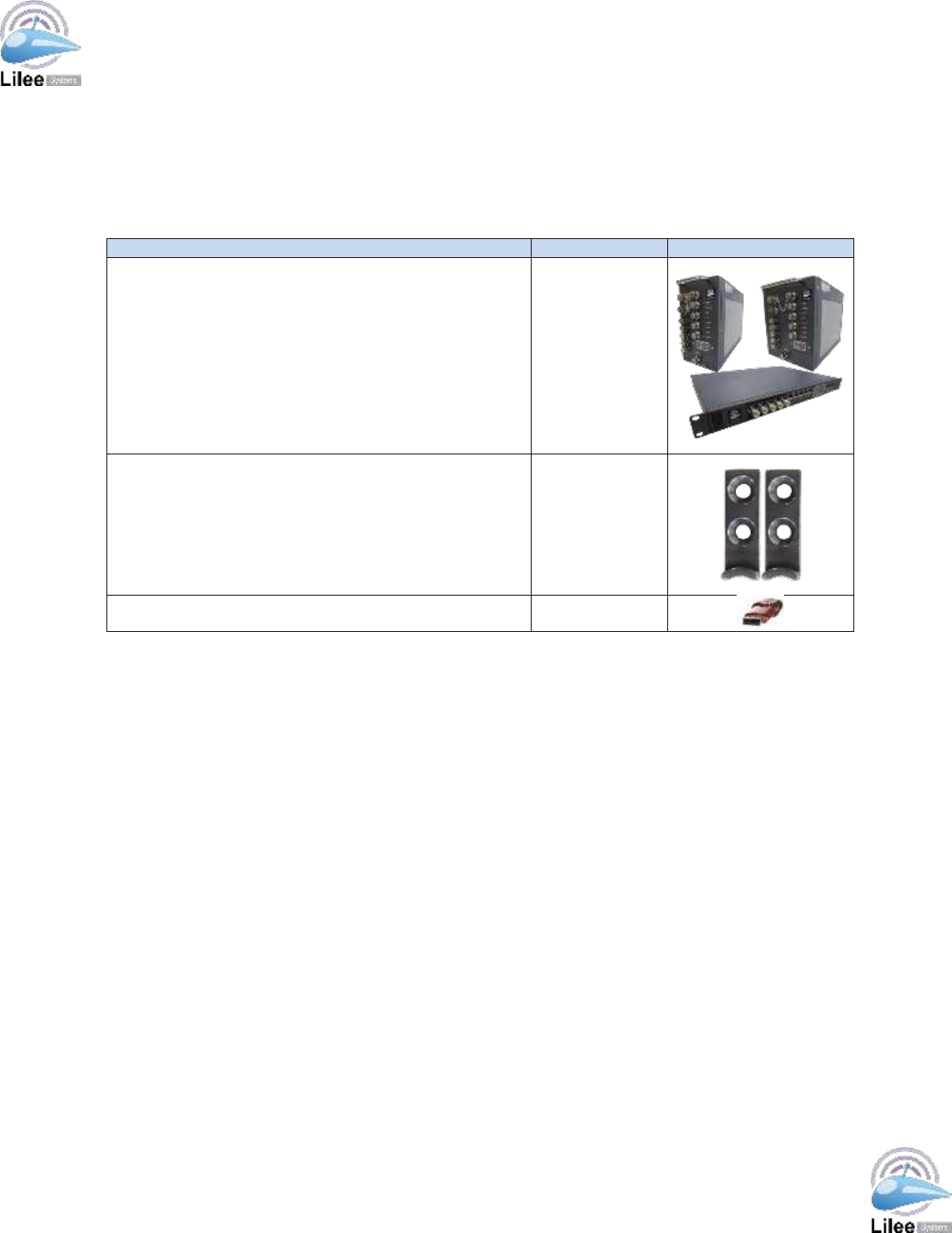
1.9 Package Checklist
The TransAir PTC-3000 is shipped with the following items. Inspect the package contents to
ensure all the components are included. If any of these items are missing or damaged,
contact the distributor or sales representative immediately.
Item and Part Number
Quantity
Image
Model #: PTC-3000 1U
Model #: PTC-3201 2MCU
Model #: PTC-3202 2MCU
Model #: PTC-3203 2MCU
Model #: PTC-3204 2MCU
Model #: PTC-3004 4MCU
Model #: PTC-3006 6MCU
1
NAS622 mounting kit with four screws (PTC-3201~4 PTC-
3004 and PTC-3006)
2 for
4MCU/6MCU
1 for 2MCU
USB Flash Drive (all models)
1
Table 1-1 – Package Checklist
Lilee Systems™ TransAir™ PTC-3000 Family User Manual
Page 9
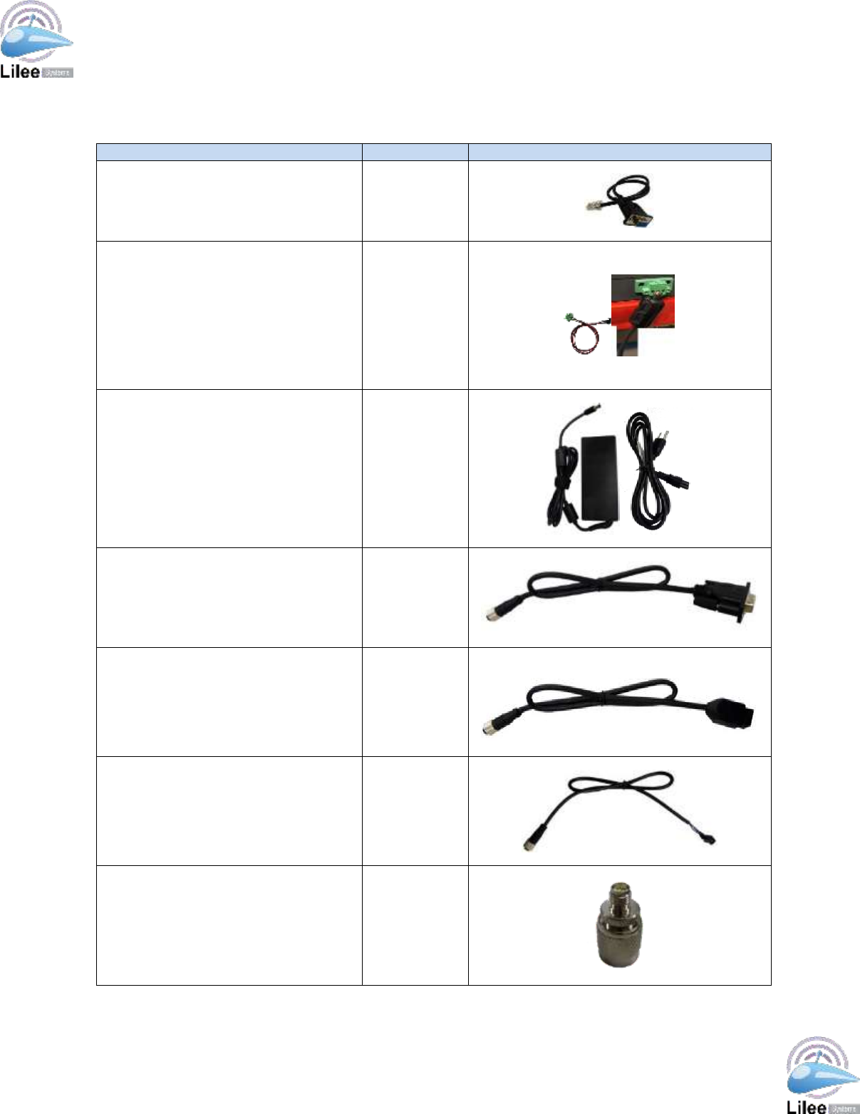
1.10 Optional Starter Kit
The following optional starter kit is available made to order.
Item and Part Number
Quantity
Image
RJ45 to DB9 cable (PTC-3001 only)
3
3-pin terminal block to
DC adapter cable (PTC-3001 only;
NOTE: Professional installer need to
provide ferrite 0461164281 or solid
version (from fair-rite.com) or
equivalent characteristic ferrite on the
power supply line position as shown in
the picture
1
AC to DC adapter + power cord (for
engineering sample purposes only; all
models)
1
M12 to DB9 cable (PTC-3201~4 PTC-
3004 and PTC-3006)
3 for 4MCU
and 6MCU/
3 or less per
2MCU model
M12 to RJ45 cable (PTC-3201~4 PTC-
3004 and PTC-3006)
2 for 4MCU
and 6MCU/2
or less per
2MCU model
DC (M12) to +19 V adapter power
cable (PTC-3201~4 PTC-3004 and
PTC-3006)
1
TNC to SMA male connector (all
models)
4 for 4MCU
and 6MCU / 4
or less for
2MCU model
Table 1-2 – Optional Starter Kit

Lilee Systems™ TransAir™ PTC-3000 Family User Manual
Page 10
2 Introduction
The Lilee Systems TransAir PTC-3000 product family includes three components: TransAir
Wayside, TransAir Base Station and TransAir Locomotive radios. The TransAir PTC product
family’s design is based on both ACSES and an interoperable train control (ITC) architecture
that in conjunction with the Lilee Mobility Controller (LMC-5x00 series) enables seamless
roaming and constant communication between central traffic control, wayside signals, and
onboard locomotive networks. This combined solution can help freight railroads and transit
operators maintain compliance with the Federal Rail Safety Improvement Act of 2008.
2.1 Features
Some of the features and benefits of the PTC-3000 are listed below:
220 MHz PTC System
Wide operating temperature range and ruggedized metal housing for hazardous
environments
3G, Wi-Fi and external satellite radio modem ( Wi-Fi is not available in Canada)
Redundant antenna
GPS Timing/Location receiver
Fast roaming for seamless wireless connections
High security with AES encryption and powerful policy based filter and Access
Control List
The PTC-3000 is designed with the following rugged features for harsh environments:
Metal housing
M12 connectors protect against shock and vibration (4MCU/6MCU locomotive units)
Hardened mounting kit for flexible, secure installation
Wide operating temperature range of -40 to 70 ⁰C
In addition, the PTC-3000 provides specifications for railroad applications:
Combines IP/Ethernet and transparent serial communications on the same network
Fast handover for rapid locomotive roaming
Status LED indicators (PWR, HEALTH, 220, 3G, WLAN, 1PPS, LAN1, LAN2) for
onsite monitoring and diagnosis
Lilee Systems™ TransAir™ PTC-3000 Family User Manual
Page 11
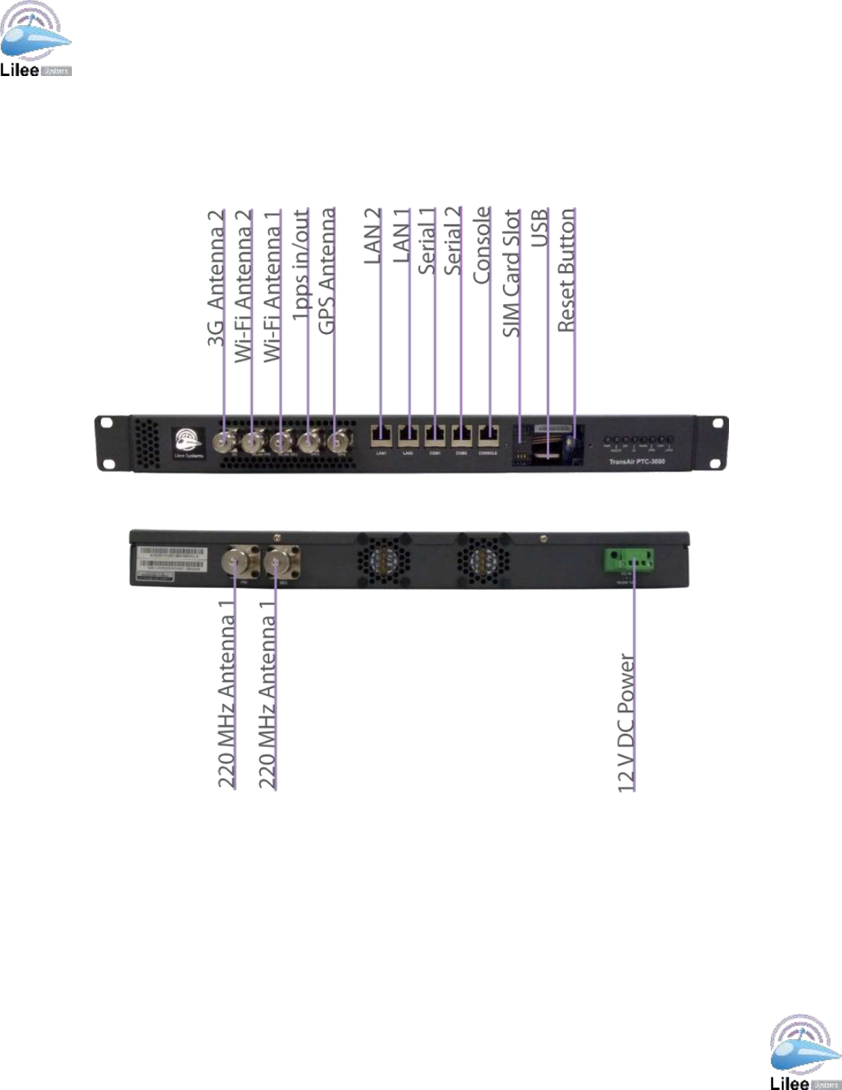
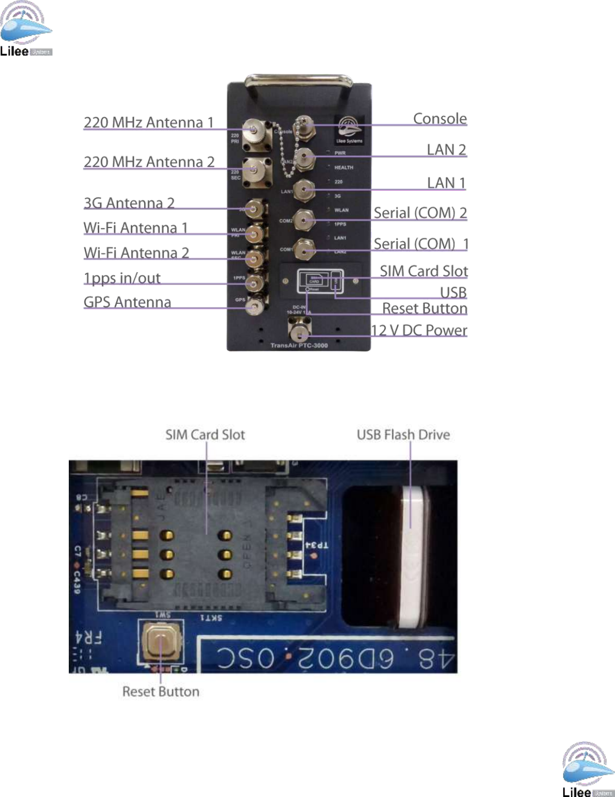
3 Interface Panel Connectors
The connectors on the interface panel of the TransAir PTC-3000 are shown in the figures below.
Figure 3-1 – PTC-3000-1U Interface Panel Connector Locations (Front and Rear) with SIM/USB/Reset panel
cover removed
Lilee Systems™ TransAir™ PTC-3000 Family User Manual
Page 12
Figure 3-2 – PTC-3004 Interface Panel Connector Locations (PTC-3006 and PTC-3201~4 will have same or
less ports and with similar functionalities)
The figure below shows the location of the SIM card slot, USB Flash Drive, and Reset button on
the PTC-3201~4 PTC-3004 and PTC-3006 units. Note: Wi-FI not available in Canada
Figure 3-3 – SIM Card Slot, USB Flash Disk, and Reset Button Locations
Lilee Systems™ TransAir™ PTC-3000 Family User Manual
Page 13
The table below lists the connectors and type on the interface panel of the TransAir PTC-3000.
Connector
Type
1U
4MCU/6MCU/2MCU
1pps In/Out
TNC
TNC
12 V DC Power
3-pin terminal block
M12 with A-coding
220 MHz Antenna 1
N-Type
N-Type
220 MHz Antenna 2
N-Type
N-Type
3G
TNC
TNC
GPS
TNC
TNC
LAN 1
RJ45
M12
LAN 2
RJ45
M12
RS-232 Console
RJ45
M12
RS-232/422/485 Serial 1
RJ45
M12
RS-232/422/485 Serial 2
RJ45
M12
SIM Card
SIM card slot
SIM card slot
USB
Type-A (female) USB
Type-A (female) USB
Wi-Fi Antenna 1
TNC
TNC
Wi-Fi Antenna 2
TNC
TNC
Table 3-1 – Interface Panel Connectors
The following section describes the connectors on the interface panel of the TransAir PTC-3000.
Refer to Figures 1 and 2 above for connector locations. Note: Wi-Fi not available in Canada
3.1 1pps In/Out
There is one 1pps in/out TNC connector on the PTC-3000 for syncing two PTC-3000 units
for lab testing.
Pin No.
Description
Center
Outer
GND
Table 3-2 – 1pps In/Out Connector Pinouts
3.2 12 V DC Power
There is one 3-pin terminal block connector on the PTC-3000-1U and one M12 with A-
coding connector on the PTC-3000-4MCU/6MCU for connecting to a 12 V DC power
adapter.
Pin No.
Description
1U (terminal block)
PTC-3201~4, PTC-3004, and PTC-3006 (M12)
1
GND
VDC
2
VDC
GND
3
GND
GND
4
N/A
VDC
Table 3-3 – 12 V DC Power Connector Pinouts
Lilee Systems™ TransAir™ PTC-3000 Family User Manual
Page 14
3.3 220 MHz Antenna
The TransAir PTC-3000 provides two N-Type connectors for connecting to 220 MHz
antennas. The table below lists the pinouts for the 220 MHz Antenna connectors.
Pin No.
Description
Center
RF
Outer
GND
Table 3-4 – 220 MHz Antenna Connector Pinouts
When selecting cables for connecting the PTC-3000 to 220 MHz antennas, quality is critical.
Poor quality cables can result in significant signal loss. Cable length should be kept at a
minimum to reduce signal loss.
Cable Type
dB/100 ft
dB/100 m
CFD-400
1.9
6.1
Table 3-5 – Coaxial Cable Signal Loss at 220 MHz
3.4 3G Antenna
There is one TNC connector for connecting to a 3G antenna. The table below lists the
pinouts for the Active 3G Antenna connector.
Pin No.
Description
Center
RF
Outer
GND
Table 3-6 – 3G Antenna Connector Pinouts
3.5 GPS Antenna
There is one TNC connector for connecting to a GPS antenna. The table below lists the
pinouts for the GPS Antenna connector.
Pin No.
Description
Center
RF
Outer
GND
Table 3-7 – GPS Antenna Connector Pinouts
Lilee Systems™ TransAir™ PTC-3000 Family User Manual
Page 15
3.6 LAN
There are two RJ45 ports on the PTC-3001 and two M12 connectors on the PTC-3201~4,
PTC-3004, and PTC-3006 for connecting to a local network. The following table lists the
pinouts for the RJ45 ports and M12 connectors.
Pin No.
Description
PTC-3000-1U (RJ45)
PTC-3201~4, PTC-3004, and
PTC-3006 (M12)
1
TX+
N/C
2
TX-
N/C
3
RX+
N/C
4
N/C
TX-
5
N/C
RX+
6
RX-
TX+
7
N/C
N/C
8
N/C
RX-
Table 3-8 – LAN Pinouts
3.7 RS-232 Console
There is one RJ45 port on the PTC-3000-1U and one M12 connector on the PTC-3201~4,
PTC-3004, and PTC-3006 (M12)for an RS-232 connection to an on-board computer or other
terminal for configuring the TransAir PTC-3000.
Pin No. (RJ45 Termination)
Description
Pin No. (DB9 Termination)
1
RTS
8
2
DTR
6
3
RX
3
4
N/C
1
5
TX
2
6
GND
5
7
DSR
4
8
CTS
7
N/A
N/C
9
Table 3-9 – RJ45 Console Port Pinouts and DB9 Termination Pinouts (PTC-3001)
See the following table for the Console port pinout definitions for the M12 connector on the
PTC-3201~4, PTC-3004, and PTC-3006 and corresponding definitions on the DB9 console
port end of a M12 to DB9 cable.
Pin No. (M12 Termination)
Description
Pin No. (DB9 Termination)
1
CTS
1
2
DTR
2
3
TX
3
4
N/C
4
5
GND
5
6
RX
6
7
DSR
7
8
RTS
8
N/A
N/C
9
Table 3-10 – M12 Console Port Pinouts and DB9 Termination Pinouts (PTC-3201~4, PTC-3004, and
PTC-3006 )
Lilee Systems™ TransAir™ PTC-3000 Family User Manual
Page 16
3.8 RS-232/422/485 Serial
There are two RJ45 ports on the PTC-3000 and two M12 connectors on the PTC-
4MCU/6MCU for connecting to RS-232/422/484 serial devices.
See the following table for the Serial port pinout definitions for the RJ45 connector on the
PTC-3000-1U and corresponding definitions on the DB9 serial port end of an M12 to DB9
cable.
Pin No. (RJ45 Termination)
Description
Pin No. (DB9 Termination)
1
RTS
8
2
DTR
6
3
RX
3
4
N/C
1
5
TX
2
6
GND
5
7
DSR
4
8
CTS
7
N/A
N/C
9
Table 3-11 – RJ45 Serial Port Pinouts and DB9 Termination Pinouts (PTC-3000-1U)
See the following table for Serial port pinout definitions for the M12 connector on the PTC-
3000-4MCU/6MCU and corresponding definitions on the DB9 serial port end of an M12 to
DB9 cable.
Pin No. (M12 Termination)
Description
Pin No. (DB9 Termination)
1
CTS
1
2
DTR
2
3
TX
3
4
N/C
4
5
GND
5
6
RX
6
7
DSR
7
8
RTS
8
N/A
N/C
9
Table 3-12 – M12 Serial Port Pinouts and DB9 Termination Pinouts (PTC-3201~4, PTC-3004, and
PTC-3006 )
3.9 Wi-Fi Antenna
Note: Wi-Fi is not available in Canada
The TransAir PTC-3000 provides two TNC connectors for connecting to Wi-Fi antennas.
The table below lists the pinouts for the Wi-Fi Antenna connectors.
Pin No.
Description
Center
RF
Outer
GND
Table 3-13 – Wi-Fi Antenna Connector Pinouts
Lilee Systems™ TransAir™ PTC-3000 Family User Manual
Page 17
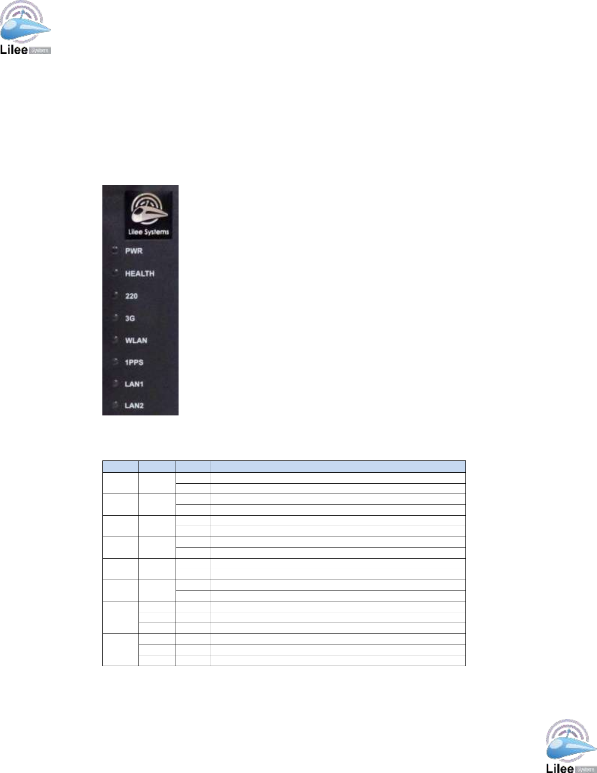
3.10 LED Indicators
The front panel of the PTC-3000 contains several LED indicators. See the figure below for
the location of each indicator.
Figure 3-4 – LED Indicators
The functions of each are described in the table below.
LED
Color
State
Description
Power
Green
On
Powered on.
Off
Powered off or no power current.
Health
Green
On
System fault has occurred.
Off
System is functioning normally.
220
Green
On
220 MHz interface is linked up.
Off
220 MHz interface link is down.
3G
Green
On
3G interface is linked up.
Off
3G interface is down.
WLAN
Green
On
WLAN interface is linked up.
Off
WLAN interface is down.
1PPS
Green
On
PTC driver has loaded and GPS 1pps signal is locked.
Off
PTC driver has not loaded and GPS 1pps signal is not locked.
LAN1
Off
No connection.
Green
On
Cable is connected.
Amber
On
Activity on link.
LAN2
Off
No connection.
Green
On
Cable is connected.
Amber
On
Activity on link.
Table 3-14 – LED Indicators
Lilee Systems™ TransAir™ PTC-3000 Family User Manual
Page 18
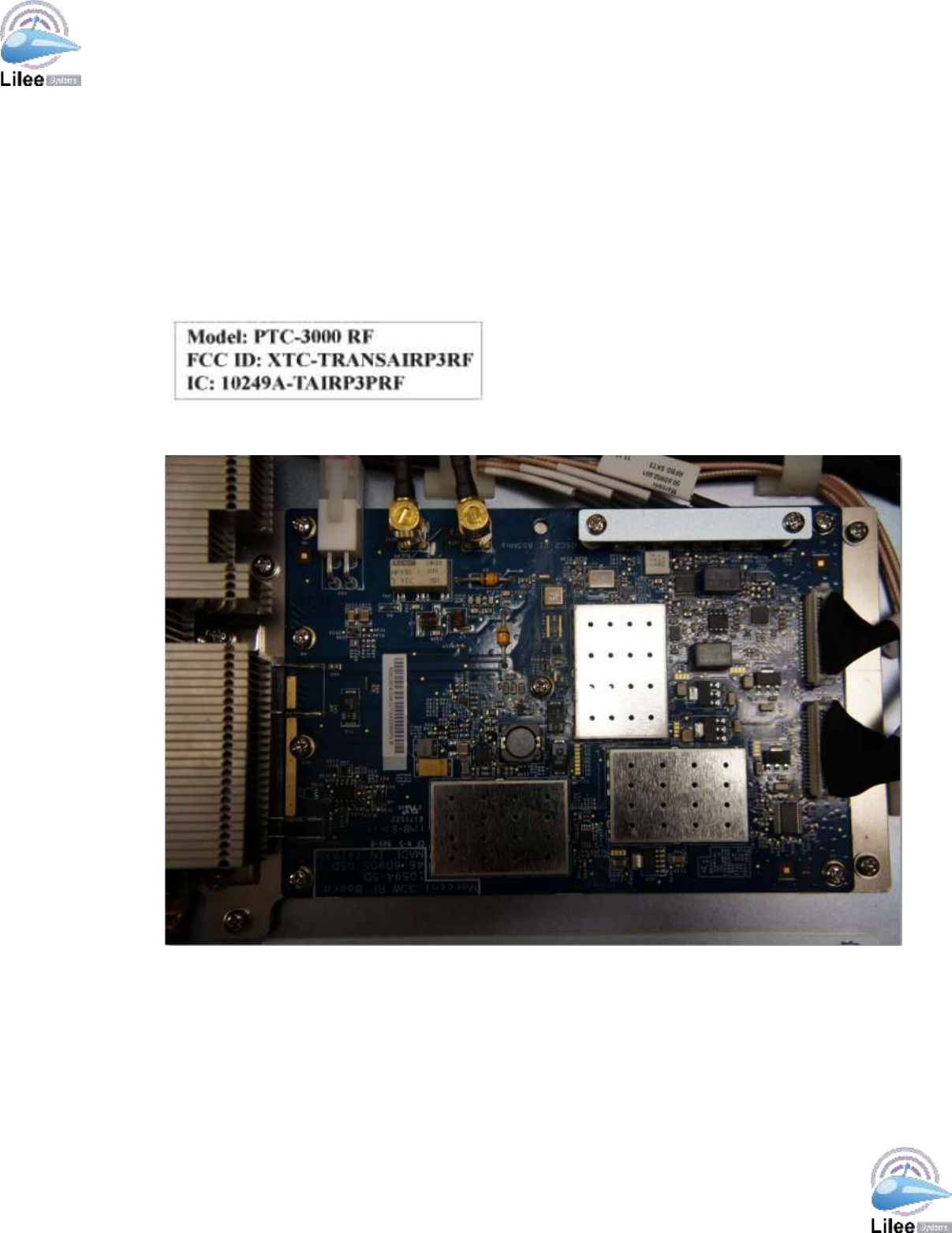
3.11 PTC-3000 RF (220MHz RF board)
The regulatory tested PTC-3000 RF (220MHz RF board) is an integral part of the wireless
communication, with 2 RF ports, PRI and SEC, digital communication protocol and control
from the host board, and single power supply input. This board is an embedded part of the
PTC-3001, PTC3004, PTC3006, PTC3201, PTC3202, and PTC-3203 systems, and the
commands to utilize this board are subpart of the commands used for the whole system.
complies with FCC/IC Modular transmitters Section label requirement. PTC-3000 RF uses a
permanently affixed label, and it's labeled with its own FCC/IC identification number (see
below). Thus, the PTC-3001, PTC-3004, PTC-3006, PTC3201, PTC-3202, and PTC-3203
shall contain the PTC-3000 RF board limited modular transmitter FCC/IC ID’s.
Figure 3-5 – PTC-3000 RF label
Figure 3-6 – 220MHz RF board

Lilee Systems™ TransAir™ PTC-3000 Family User Manual
Page 19
4 Installation
4.1 Connecting Cables
Please see Chapter 3 Interface Panel Connectors for pinout details of the connectors on
the PTC-3000. The following section describes how to connect cables and devices to the
PTC-3000. Connect according to your configuration requirements.
4.1.1 RJ45 to DB9 Console Cable (PTC-3000-1U)
Step 1: Locate the RJ45 Console connectors. The location of the RJ45 Console port
connector is shown in Figure 1.
Step 2: Align the connectors. Align the RJ45 connector on the LAN cable with the RJ45
Console port connector on the PTC-3000.
Step 3: Insert the RJ45 to DB9 cable RJ45 connector. Once aligned, gently insert the LAN
cable RJ45 connector into the PTC-3000 RJ45 connector.
Step 4: Connect to a PC. Locate a serial port connector on the PC to be used to configure the
PTC-3000.
Step 5: Insert the DB9 cable RJ45 connector. Insert the LAN cable RJ45 cable connector into
the RJ45 connector to a PC.
4.1.2 M12 to DB9 Console Cable (PTC-3201~4, PTC-3004, and PTC-3006 (M12))
Step 1: Locate the M12 Console connectors. The location of the M12 Console connectors is
shown in Figure 2.
Step 2: Align the connectors. Align the M12 connector on the LAN cable with the M12
Console connectors on the PTC-3000.
Step 3: Insert the LAN cable RJ45 connector. Once aligned, gently insert the LAN cable
RJ45 connector into the PTC-3000 RJ45 connector.
Step 4: Connect to a LAN router/switch. Locate the RJ45 connector on the PC to be used to
configure the PTC-3000.
Step 5: Insert the LAN cable RJ45 connector. Insert the LAN cable RJ45 cable connector into
the RJ45 connector on the LAN router or switch.

Lilee Systems™ TransAir™ PTC-3000 Family User Manual
Page 20
4.1.3 RJ45 LAN Cable (PTC-30001)
Step 1: Locate the RJ45 LAN connectors. The locations of the LAN connectors are shown in
Figure 1.
Step 2: Align the connectors. Align the RJ45 connector on the LAN cable with one of the
RJ45 connectors on the PTC-3000.
Step 3: Insert the LAN cable RJ45 connector. Once aligned, gently insert the LAN cable
RJ45 connector into the PTC-3000 RJ45 connector.
Step 4: Connect to a LAN router/switch. Locate the RJ45 connector on the LAN router or
switch.
Step 5: Insert the LAN cable RJ45 connector. Insert the LAN cable RJ45 cable connector into
the RJ45 connector on the LAN router or switch.
4.1.4 M12 to RJ45 LAN Cable (PTC-30001)
Step 1: Locate the M12 LAN connectors. The locations of the LAN connectors are shown in
Figure 2.
Step 2: Align the connectors. Align the M12 connector on the LAN cable with one of M12 LAN
connectors on the PTC-3000.
Step 3: Insert the LAN cable M12 connector. Once aligned, gently insert the LAN cable M12
connector into the PTC-3000 M12 connector.
Step 4: Secure the M12 connector. Turn the locking cover of the M12 connector end of the
cable clockwise to secure the cable to the connector on the PTC-3000.
Step 5: Connect to a LAN router or switch. Locate the RJ45 connector on the LAN router or
switch.
Step 6: Insert the LAN cable RJ45 connector. Insert the LAN cable RJ45 cable connector into
the RJ45 connector on the LAN router or switch.
4.1.5 RJ45 to DB9 Serial Device Cable (PTC-30001)
Step 1: Locate the RJ45 serial connector. The location of the RJ45 serial port connector is
shown above in Figure 1.
Step 2: Insert the RJ45 to DB-9 cable. Insert the RJ45 end of the cable into the RJ45
connector of the PTC-3000.
Step 3: Insert the serial connector. Insert the DB-9 connector of a serial device into the DB-9
connector on the cable.
Step 4: Secure the connector. Secure the serial device connector to the external interface by
tightening the two retention screws on either side of the connector.

Lilee Systems™ TransAir™ PTC-3000 Family User Manual
Page 21
4.1.6 M12 to DB9 Serial Device Cable (PTC-3201~4, PTC-3004, and PTC-3006)
Step 1: Locate the M12 serial connector. The location of the M12 serial port connector is
shown above in Figure 2.
Step 2: Insert the M12 to DB-9 cable. Insert the M12 end of the cable into the M12 serial
connector of the PTC-3000.
Step 3: Secure the M12 connector. Turn the locking cover of the M12 connector end of the
cable clockwise to secure the cable to the connector on the PTC-3000.
Step 4: Insert the serial connector. Insert the DB-9 connector of a serial device into the DB-9
connector on the cable.
Step 5: Secure the connector. Secure the serial device connector to the external interface by
tightening the two retention screws on either side of the connector.
4.1.7 TNC to SMA Male Connector for Wi-Fi Antennas with SMA Connectors
Step 1: Locate the TNC Wi-Fi connector. The location of the TNC Wi-Fi antenna connector is
shown above in Figure 1 and Figure 2.
Step 2: Insert the TNC to SMA connector (with center pin). Insert the TNC end of the
connector into the TNC connector of the PTC-3000.
Step 3: Secure the TNC to SMA connector. Turn the locking cover of the TNC connector end
of the TNC to SMA connector clockwise to secure connector on the PTC-3000.
Step 4: Connect a Wi-Fi antenna. Insert the SMA connector end of a Wi-Fi antenna to the
SMA connector end of the TNC to SMA connector.
4.1.8 TNC to SMA Female Connector for GPS or 3G
Step 1: Locate the TNC connector for GPS, 3G. The location of the TNC connectors is shown
above in Figure 1 and Figure 2.
Step 2: Insert the TNC to SMA connector (without center pin). Insert the TNC end of the
connector into the TNC connector of the PTC-3000.
Step 3: Secure the TNC to SMA connector. Turn the locking cover of the TNC connector end
of the TNC to SMA connector clockwise to secure connector on the PTC-3000.
Step 4: Connect to a GPS or 3G antenna. Insert the SMA connector end of a GPS or 3G
antenna (or antenna cable) to the SMA connector end of the TNC to SMA connector.

Lilee Systems™ TransAir™ PTC-3000 Family User Manual
Page 22
4.1.9 TNC to TNC Cable for Syncing PTC-3000 Units
Step 1: Locate the 1pps TNC connectors. The location of the 1pps TNC connectors is shown
above in Figure 1 and Figure 2.
Step 2: Insert the TNC cable. Insert one end of the TNC connector into the 1pps TNC
connector of one PTC-3000.
Step 3: Secure the TNC cable. Turn the locking cover of the TNC connector end of the TNC
connector clockwise to secure connector on the PTC-3000.
Step 4: Connect to second PTC-3000. Repeat Steps 2 and 3 to connect to the TNC cable to
the 1pps connector on the second PTC-3000.
4.1.10 Power Cable and Power Adapter
When other cable connections are complete, connect the PTC-3000 to a power source
according to the following steps.
Step 1: Locate the power connector. Please see Figure 1 and Figure 2 to locate the power
connector on the PTC-3000.
Step 2: Insert the 3-pin terminal block to +19 V power cable or M12 to +19 V power cable.
Insert the 3-pin terminal block end or M12 end of the power cable into the 3-pin terminal
block power connector or M12 connector on the PTC-3000.
Step 3: Insert the +19 V end of the power cable to the power adapter.
Step 4: Connect the power cord to the power adapter.
Step 5: Connect the power cord to the power outlet.
Step 0:
4.2 USB Flash Disk Removal and Installation
4.2.1 Remove SIM/USB/Reset Panel Cover
Step 1: Locate Cover. Locate the SIM/USB/Reset button panel cover on the front panel of the
PTC-3000.
Step 2: Unfasten Screws. Using a screwdriver, unfasten the screws by turning
counterclockwise.
Step 3: Remove Cover.
Lilee Systems™ TransAir™ PTC-3000 Family User Manual
Page 23
Figure 4-1 – SIM/USB/Reset Panel Cover
4.2.2 USB Flash Drive Removal
Step 1: Grasp USB Flash Drive from the top and bottom of the flat surface as shown in the
figure below (yellow arrows).
Step 2: Pull outward to remove (green arrow).
Figure 4-2 – USB Flash Drive Removal (1U unit shown)
Lilee Systems™ TransAir™ PTC-3000 Family User Manual
Page 24
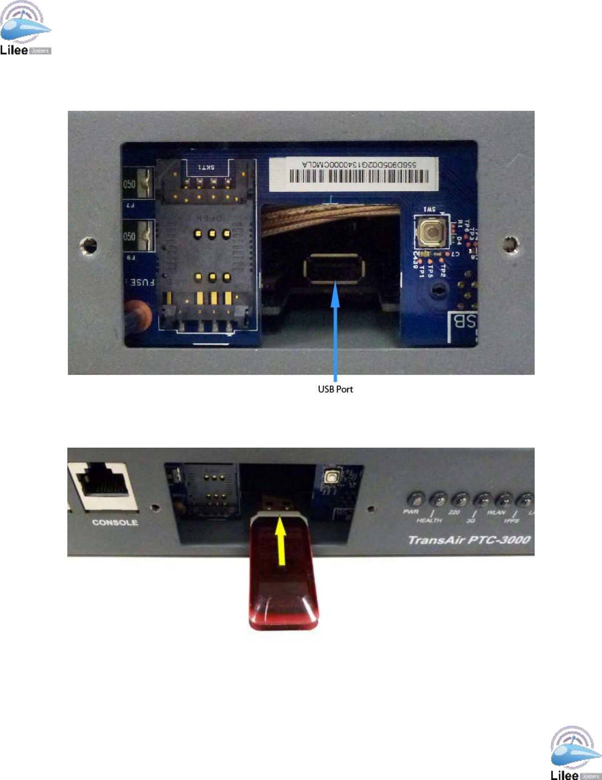
4.2.3 USB Flash Drive Installation
Step 1: Locate USB port (see figure below).
Figure 4-3 – USB Port Location (1U unit shown)
Step 2: Insert USB Flash Drive into USB port as shown in the figure below.
Figure 4-4 – USB Flash Drive Installation (1U unit shown)
Lilee Systems™ TransAir™ PTC-3000 Family User Manual
Page 25
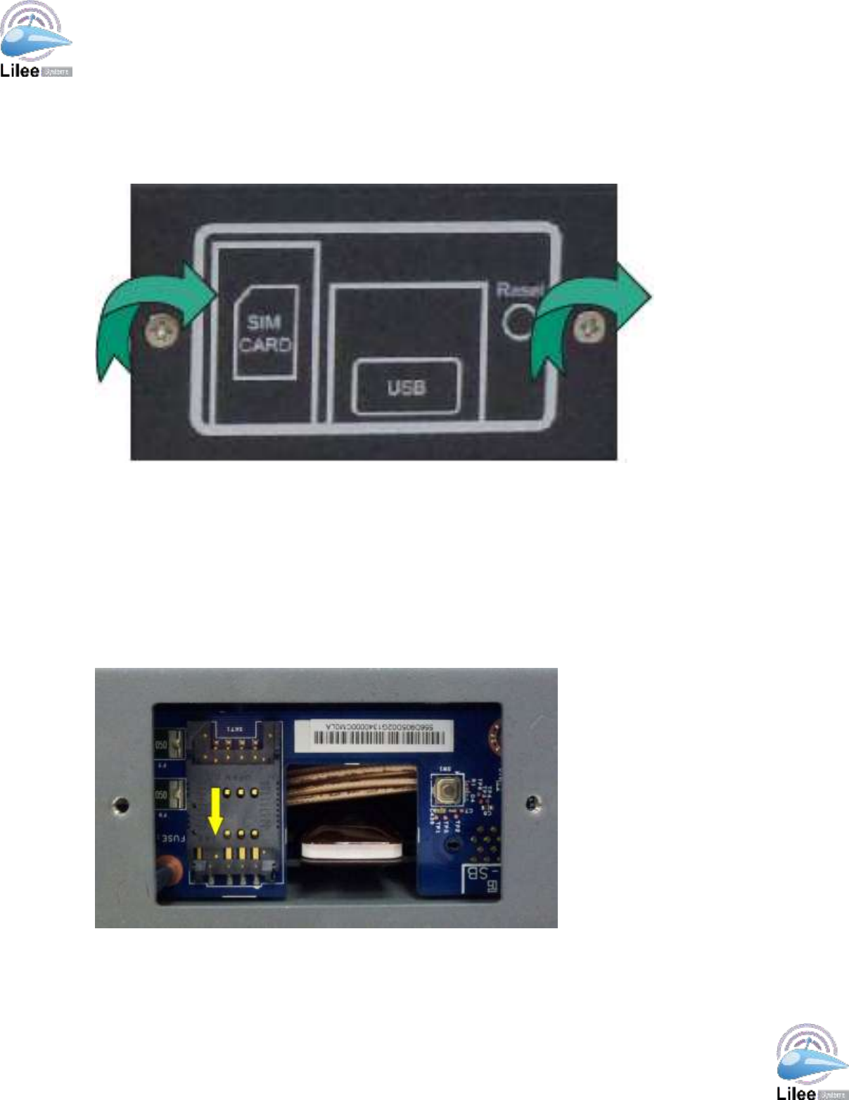
4.2.4 Replace SIM/USB/Reset Panel Cover
Step 1: Replace Cover.
Step 2: Refasten screws. Using a screwdriver, fasten the screws by turning clockwise.
Figure 4-5 – Replace SIM/USB/Reset Panel Cover
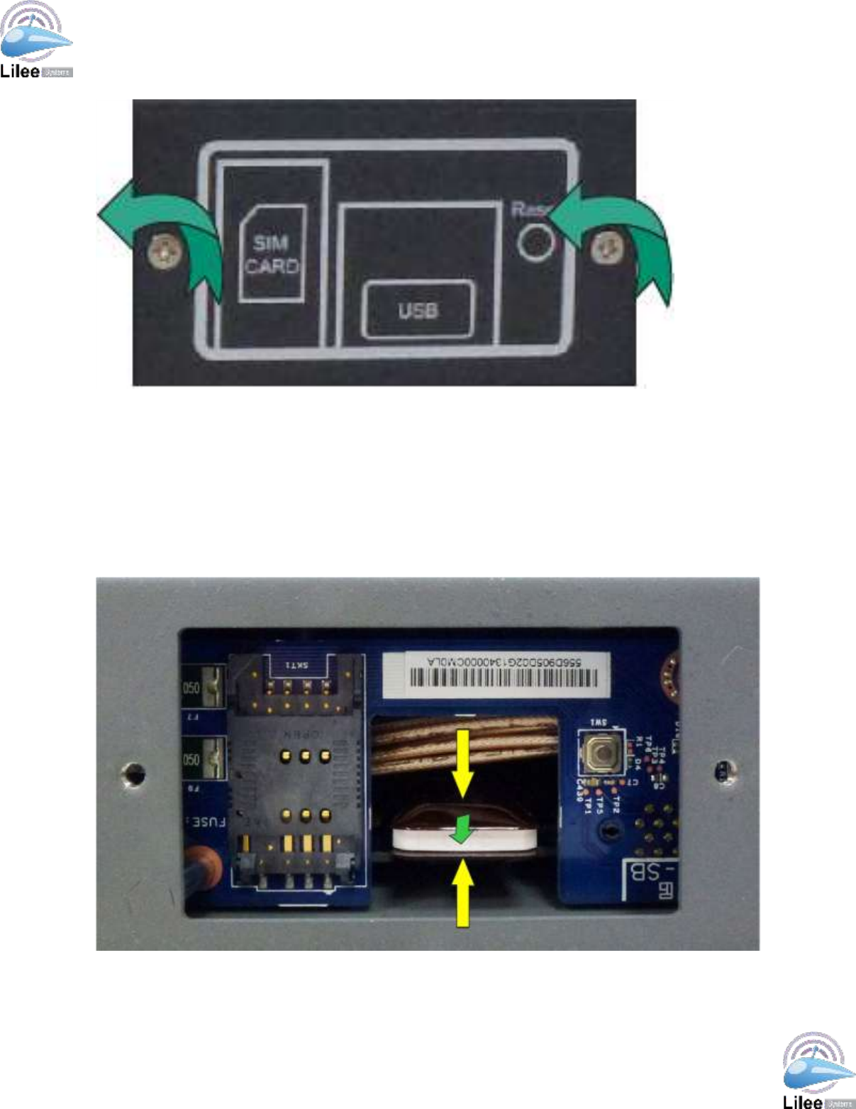
4.3 SIM Card Installation
Step 1: Remove SIM/USB/Reset Panel Cover as in 4.2.1 Remove SIM/USB/Reset Panel
Cover.
Step 2: Open SIM card slot protective cover. Slide SIM card slot protective cover down as
show below (yellow arrow). Open SIM card slot protective cover.
Figure 4-6 – Slide SIM Card Slot Protective Cover Down

Lilee Systems™ TransAir™ PTC-3000 Family User Manual
Page 26
Step 3: Insert SIM card. Slide SIM card into the protective cover with the card’s metallic
contact facing toward the slot.
Step 4: Close SIM card slot protective cover.
Step 5: Lock SIM card slot protective cover. Slide SIM card slot upward.
Step 6: Replace SIM/USB/Reset Panel Cover as in 4.2.4 Replace SIM/USB/Reset Panel
Cover.
Lilee Systems™ TransAir™ PTC-3000 Family User Manual
Page 27
5 Configuring the PTC-3000
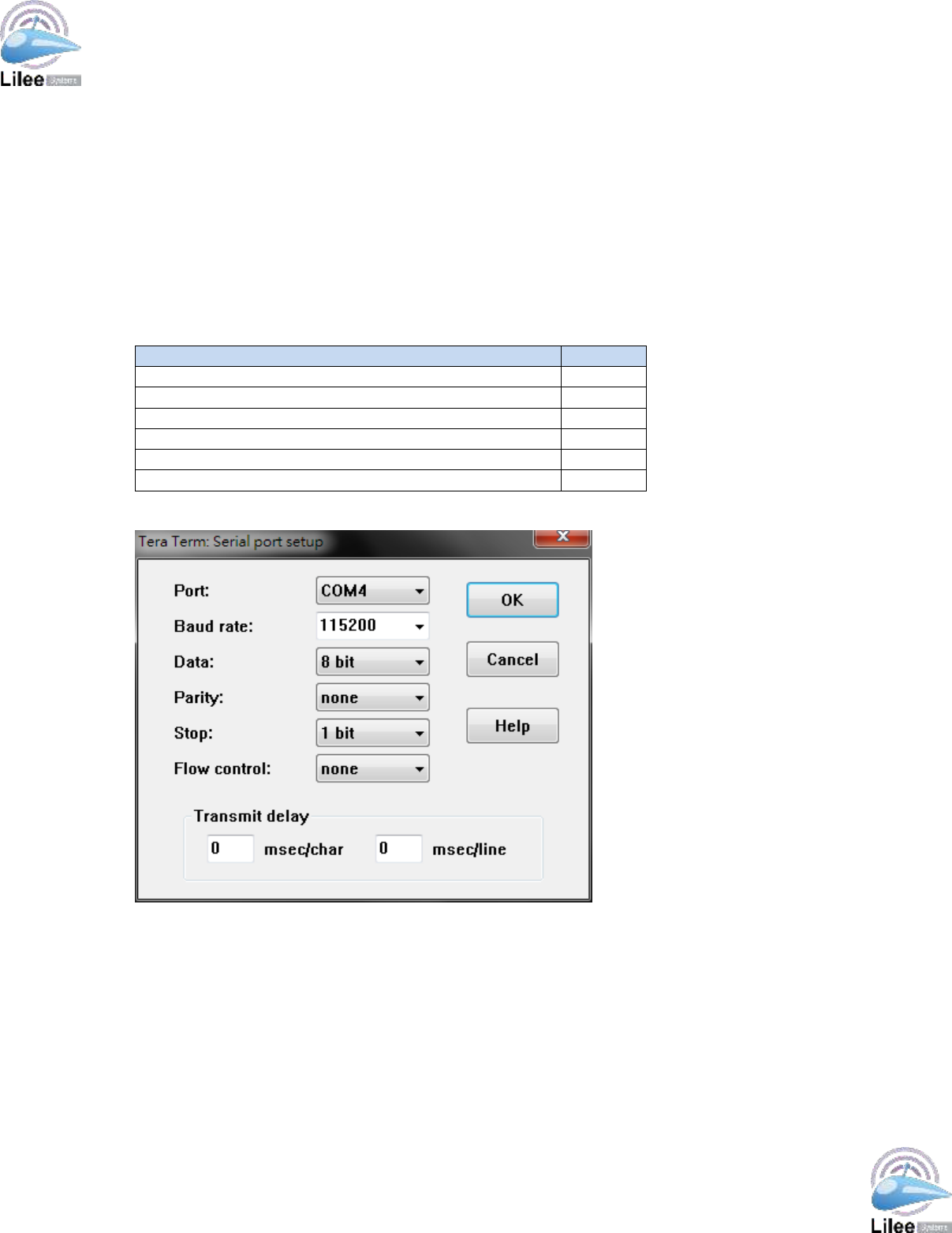
5.1 Configuration Commands
To begin configuring the PTC-3000, use a terminal emulation program like HyperTerminal,
PuTTy, or Tera Term to connect to the PTC-3000 and enter configuration commands.
Configure the terminal emulation program serial port settings as in the table below (also see
example configuration in Tera Term below):
Terminal Emulation Program Serial Port Settings
Value
Port
COM#
Baud Rate
115200
Data
8 bit
Parity
None
Stop
1 bit
Flow Control
None
Table 5-1 – LED Indicators
Figure 5-1 – Serial Port Settings

Lilee Systems, Ltd
2905 Stender Way, Suite 78
Santa Clara, CA 95054
Tel: 408.988.8672
www.lileesystems.com
information@lileesystems.com