Lilee Systems TRANSAIRP3004 TransAir PTC-3004 User Manual
Lilee Systems, Ltd. TransAir PTC-3004 Users Manual
UserManual.wiki
>
Lilee Systems
>
TRANSAIRP3004 User Manual
>
Users Manual
Contents
1.
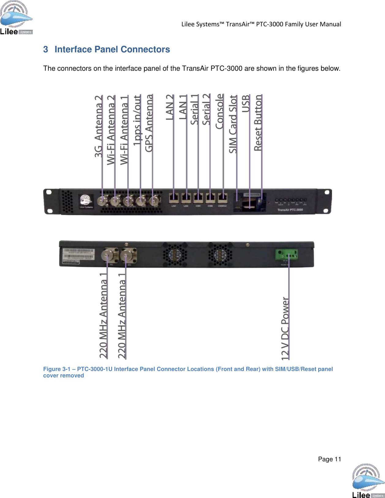
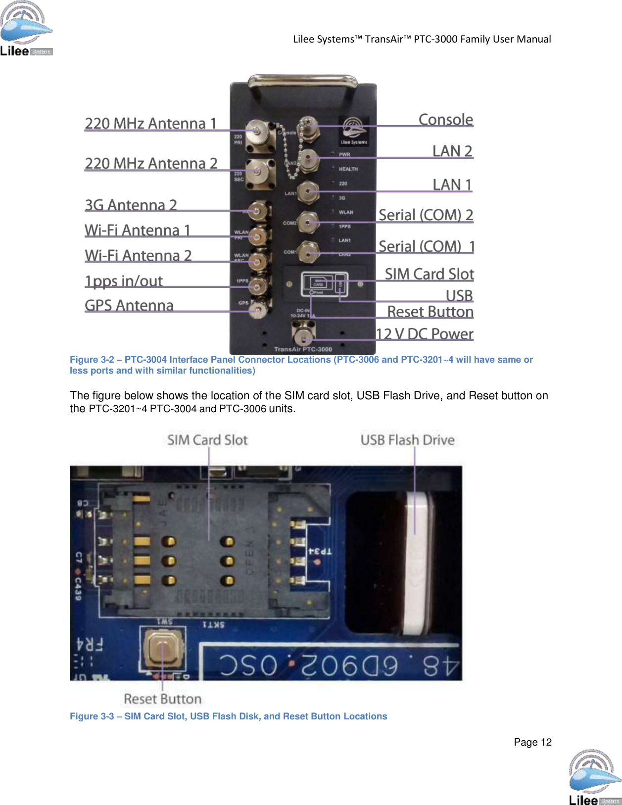
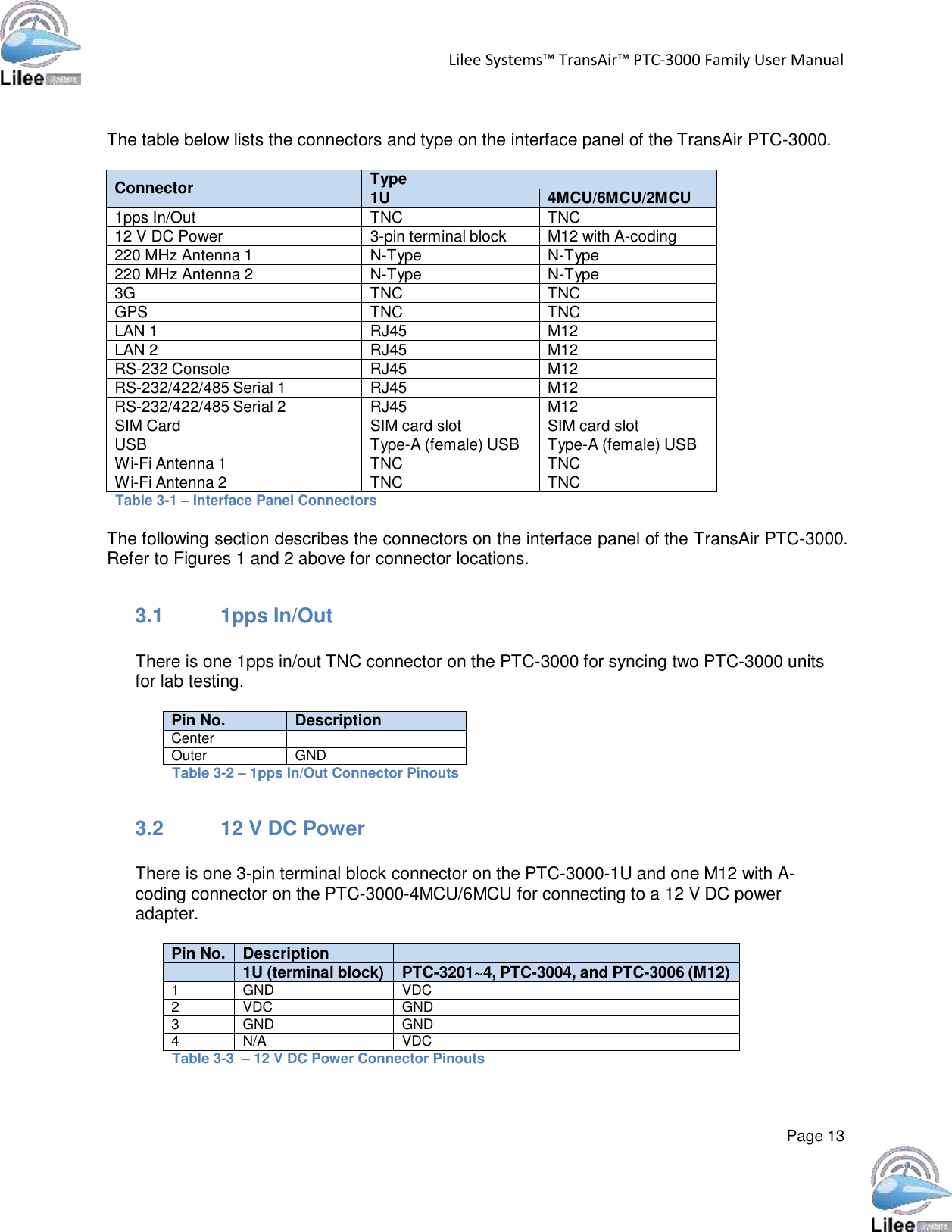
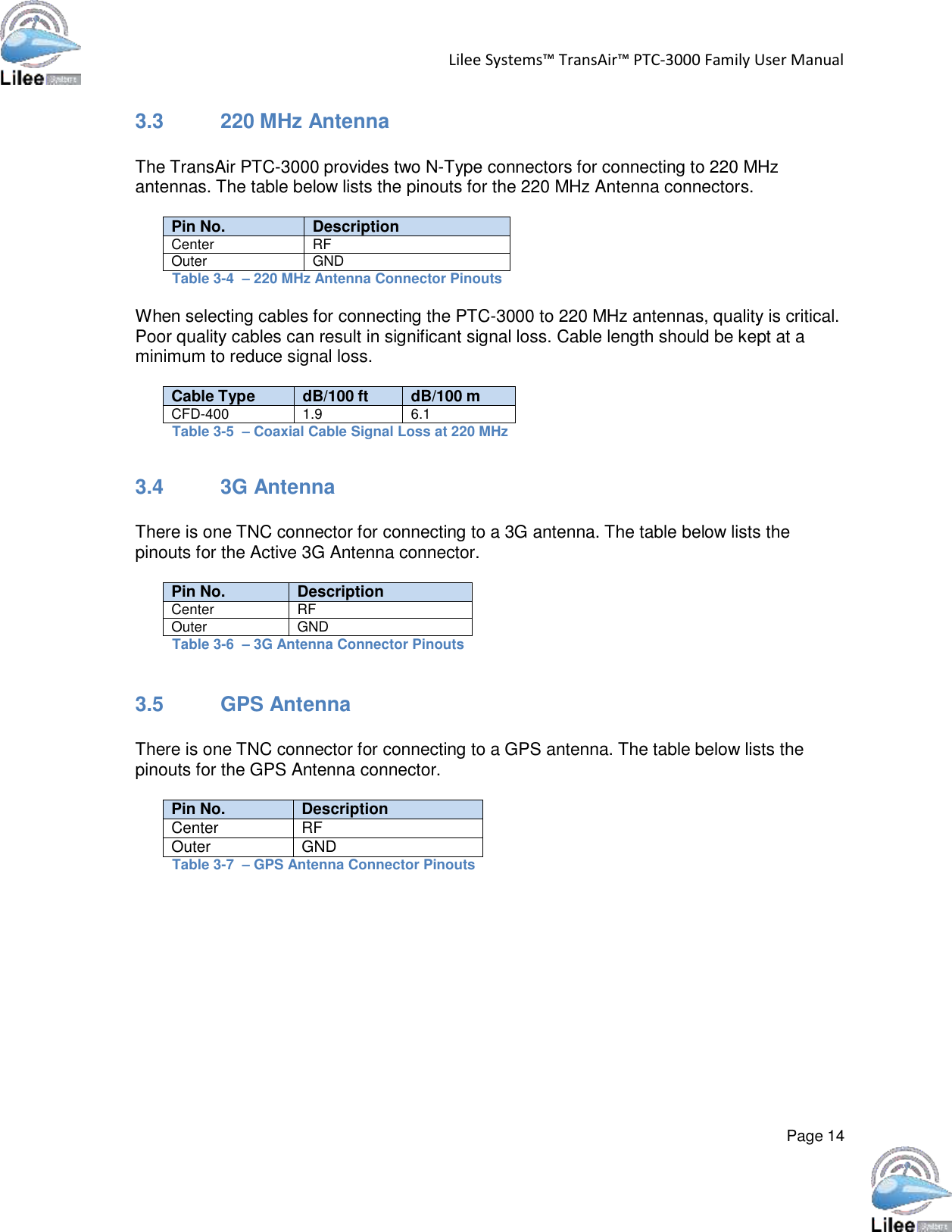
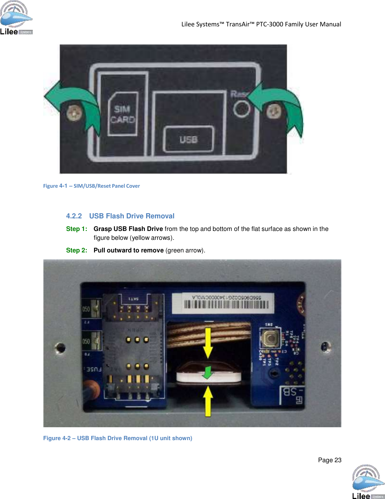
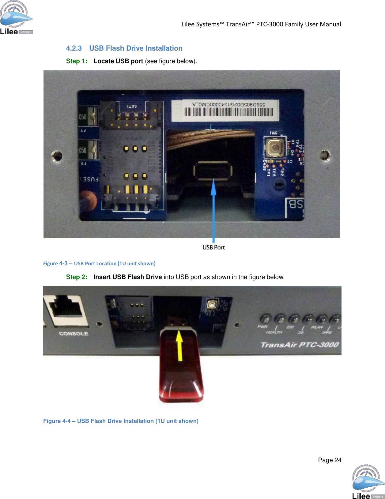
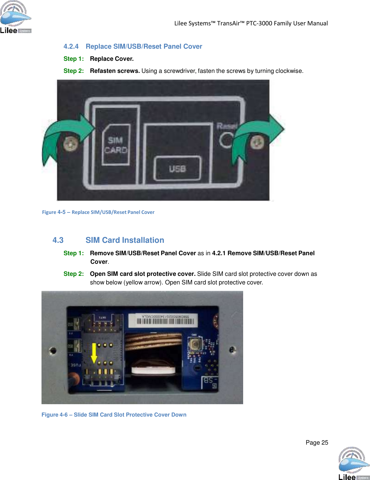
Users Manual
2.
TransAir 3dBi Omni Antenna
3.
TransAir 13dBi Sector Antenna
4.
Dual Yagi Antenna
5.
Yagi Antenna
6.
220MHz 3dBi Antenna
7.
WiFi Antenna
8.
3G Antenna
Users Manual
Navigation menu
Upload a User Manual
Namespaces
Wiki Guide
HTML
PDF
Info
Views
User Manual
Discussion / Help
Navigation