Lin Man Power Technology AJ102 Data Concentrator Unit User Manual
Lin Man Power Technology Inc., Data Concentrator Unit
User Manual
Title:
AJ102 Data Concentrator Unit User Manual
Ver.
1.4
Page:
1 of 23
Data Concentrator Unit
Model No. AJ102
Version: 1.4
Release Date: 2018.07.16
Safety Instruction

Title:
AJ102 Data Concentrator Unit User Manual
Ver.
1.4
Page:
2 of 23
Read all safety information and operating instructions before using the DCU to avoid personal
injury.
This device complies with Part 15 of the FCC Rules. Operation is subject to the following two conditions: (1) this
device may not cause harmful interference, and (2) this device must accept any interference received, including
interference that may cause undesired operation.
Caution: The user is cautioned that changes or modifications not expressly approved by the party responsible for
compliance could void the user's authority to operate the equipment.
Note: This equipment has been tested and found to comply with the limits for a Class B digital device,
pursuant to part 15 of the FCC Rules. These limits are designed to provide reasonable protection
against harmful interference in a residential installation. This equipment generates, uses and can
radiate radio frequency energy and, if not installed and used in accordance with the instructions, may
cause harmful interference to radio communications. However, there is no guarantee that interference
will not occur in a particular installation. If this equipment does cause harmful interference to radio or
television reception, which can be determined by turning
the equipment off and on, the user is encouraged to try to correct the interference by one or more of the
following measures:
—Reorient or relocate the receiving antenna.
—Increase the separation between the equipment and receiver.
—Connect the equipment into an outlet on a circuit different from that to which the receiver is
connected.
—Consult the dealer or an experienced radio/TV technician for help.
This equipment complies with FCC radiation exposure limits set forth for an uncontrolled environment. This
equipment should be installed and operated with a minimum distance of 20cm between the radiator and any part of
your body.
Installation
- DCU must be installed with additional applicable protection SPDs(limit transient voltage to 2500Vac) and
a circuit-breaker(rating 10 A) provided external to the equipment prior to the input, limit over voltage
category to OVII.
- DCU should be installed inside an IP54 outdoor used cabinet (outdoor enclosure, material: SABIC
INNOVATIVE PLASTICS B V, type 503R (f1), 3.0mm thickness, flammability 5VA), which is restricted
access area. Access can only be gained by users with tools or other securities controlled by the authority
responsible for the location, who acknowledge the restriction reasons and precautions.
- DCU should be used with power wiring Min. 0.1A, 17AWG, and wiring screw terminal Min. 3.5 mm
diameter.
Power must be cut off before installation or removal of the DCU. Refer to “DCU Installation” for more
details.
Operation
1. Do not break the seal and remove terminal cover without authorization.
2. Never remove the DCU main cover while the DCU is in operation. The exposed circuits and
components may lead to injuries or damage to the DCU.
3. DCU working voltage should be less than 120% nominal voltage (120%Un). Long time over voltage
may lead to damage the DCU.
4. Do not operate the DCU with wet hands.

Title:
AJ102 Data Concentrator Unit User Manual
Ver.
1.4
Page:
3 of 23
All Rights Reserved
No part of this document can be reproduced or transmitted in any form or by any means without
prior written consent of Shenzhen Kaifa Technology (Chengdu) Co., Ltd.
Notice
The information in this document is subject to change without notice. Every effort has been made
in the preparation of this document to ensure accuracy of the contents but all statements,
information and recommendations in this document do not constitute the warranty of any kind,
expressed or implied.
For service and technical support information, please contact:
SHENZHEN KAIFA TECHNOLOGY (Chengdu) CO., LTD
No.1218 Hezuo Rd., Hi-Tech Development Zone (West), Chengdu, P.R.C.
Postcode: 611731
Tel: 86-28-65706888
http://www.kaifa.cn

Title:
AJ102 Data Concentrator Unit User Manual
Ver.
1.4
Page:
4 of 23
Content
1 OVERVIEW ................................................................................................................................................. 6
2 ABBREVIATION ......................................................................................................................................... 6
3 GENERAL DESCRIPTION ........................................................................................................................ 7
3.1 FRONT VIEW AND REAR VIEW ......................................................................................................... 7
3.2 TECHNICAL FEATURES ..................................................................................................................... 8
4 FUNCTION CHARACTERISTICS ........................................................................................................... 9
4.1 CLOCK MANAGEMENT ..................................................................................................................... 9
4.2 SYNCHRONIZE METER CLOCK ......................................................................................................... 9
4.3 NODE DISCOVERY AND AUTO-ROUTING .......................................................................................... 9
4.4 AUTOMATICALLY METER DATA COLLECTION .................................................................................. 9
4.4.1 Re-collect the Data .................................................................................................................. 9
4.4.2 Storage Capacity ................................................................................................................... 10
4.4.3 Data Upload to Central System ............................................................................................. 10
4.5 ON DEMAND REQUEST AND RESPONSE TRANSFERRING ................................................................ 10
4.6 DCU FIRMWARE UPGRADE ............................................................................................................ 10
4.7 METER FIRMWARE UPGRADE ........................................................................................................ 10
4.8 SELF-DIAGNOSE AND WORKING STATUS ........................................................................................ 11
4.9 EVENT LOGS .................................................................................................................................. 11
4.10 LED INDICATORS ........................................................................................................................... 12
5 COMMUNICATION INTERFACES ....................................................................................................... 13
5.1 OPTICAL PORT COMMUNICATION................................................................................................... 13
5.2 WAN COMMUNICATION ................................................................................................................. 13
5.2.1 3G Communication................................................................................................................ 13
5.2.2 Ethernet Communication ....................................................................................................... 14
5.3 LAN COMMUNICATION .................................................................................................................. 14
5.3.1 RF Communication................................................................................................................ 14
5.3.2 RS-485 Communication ......................................................................................................... 14
6 SECURITY ................................................................................................................................................. 15
6.1 PHYSICAL SECURITY ...................................................................................................................... 15
6.2 COMMUNICATION SECURITY .......................................................................................................... 15
6.3 KEYS OF DCU ................................................................................................................................ 15
6.4 COMMUNICATION SECURITY TO METERS....................................................................................... 15
7 TRANSPORTATION AND STORAGE ................................................................................................... 16
8 DCU INSTALLATION .............................................................................................................................. 16
8.1 INSTALLATION ENVIRONMENT ....................................................................................................... 16
8.2 DIMENSION AND WEIGHT .............................................................................................................. 16
8.3 WIRING DIAGRAM AND AUXILIARY TERMINALS ........................................................................... 16
8.4 INSTALLATION GUIDE .................................................................................................................... 17
8.4.1 What You Need....................................................................................................................... 17

Title:
AJ102 Data Concentrator Unit User Manual
Ver.
1.4
Page:
5 of 23
8.4.2 DCU Installation ................................................................................................................... 17
ANNEX 1 REFERENCE STANDARDS .............................................................................................................. 21
ANNEX 2 RF COMMUNICATION CHANNEL ................................................................................................ 22

Title:
AJ102 Data Concentrator Unit User Manual
Ver.
1.4
Page:
6 of 23
1 Overview
The AJ102 data concentrator unit (DCU) is capable of providing automatic data collection and remote
control of smart electricity meters in AMI system. As a part of AMI solution, the DCU is used for managing
meter, monitoring meter work status, collecting and storing meter data, transferring the data to central
system, and transfer the message/command from the central system to meters or vice versa.
2 Abbreviation
AMI
Advance Metering Infrastructure
DCU
Data Concentrator Unit
HES
Head End System
MDMS
Meter Data Management System
RF
Radio Frequency
WAN
Wide Area Network
LAN
Local Area Network
RTC
Real Time Clock
HLS
High Level Security
SNTP
Simple Network Time Protocol
Title:
AJ102 Data Concentrator Unit User Manual
Ver.
1.4
Page:
7 of 23
3 General Description
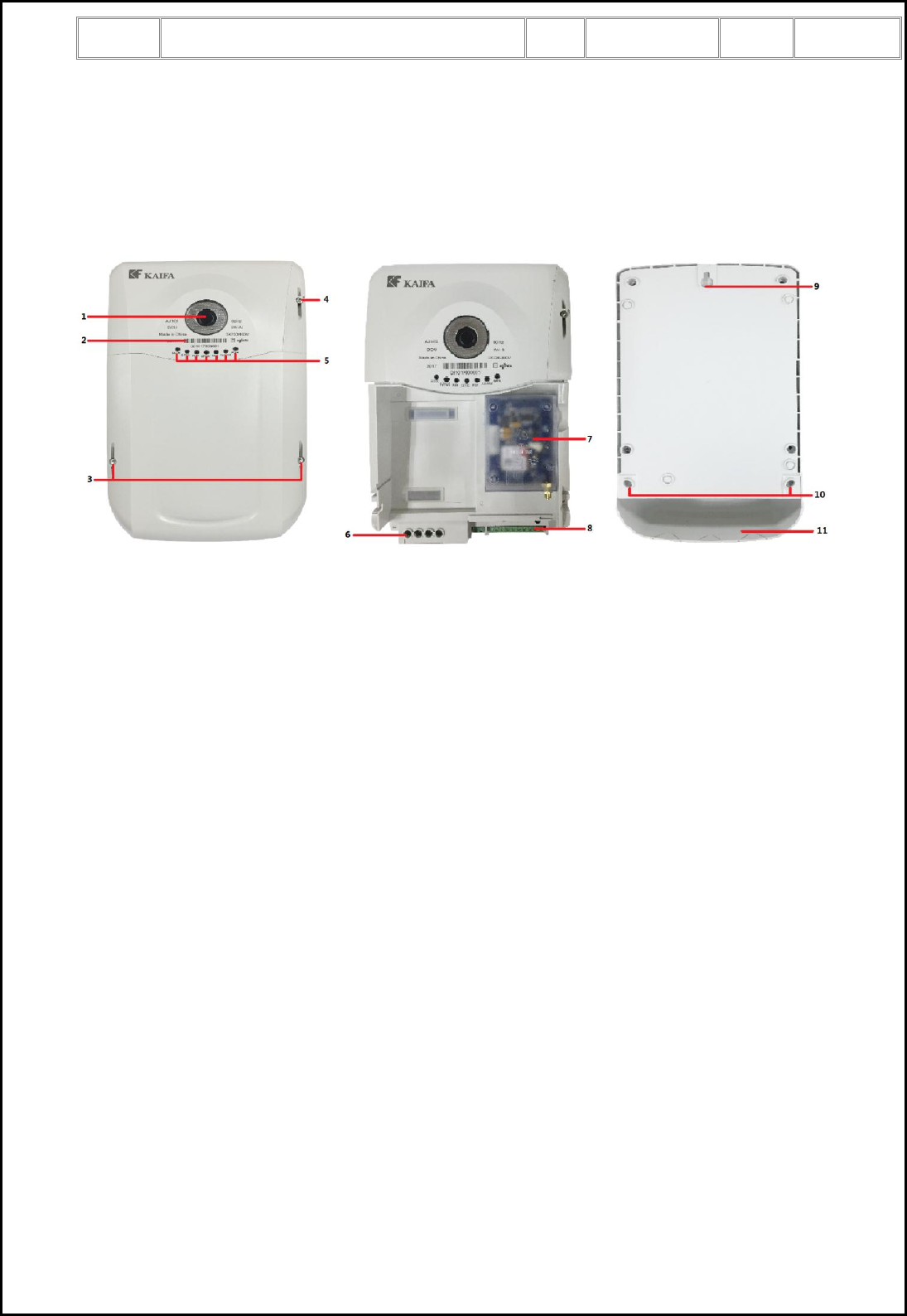
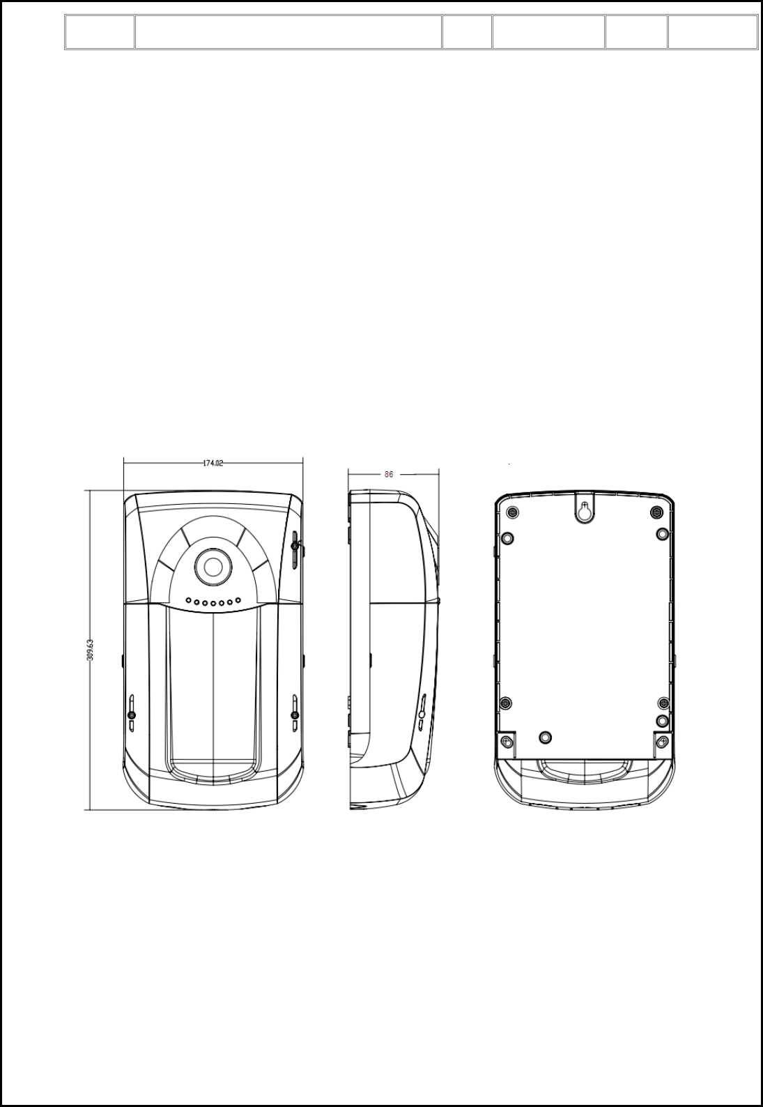
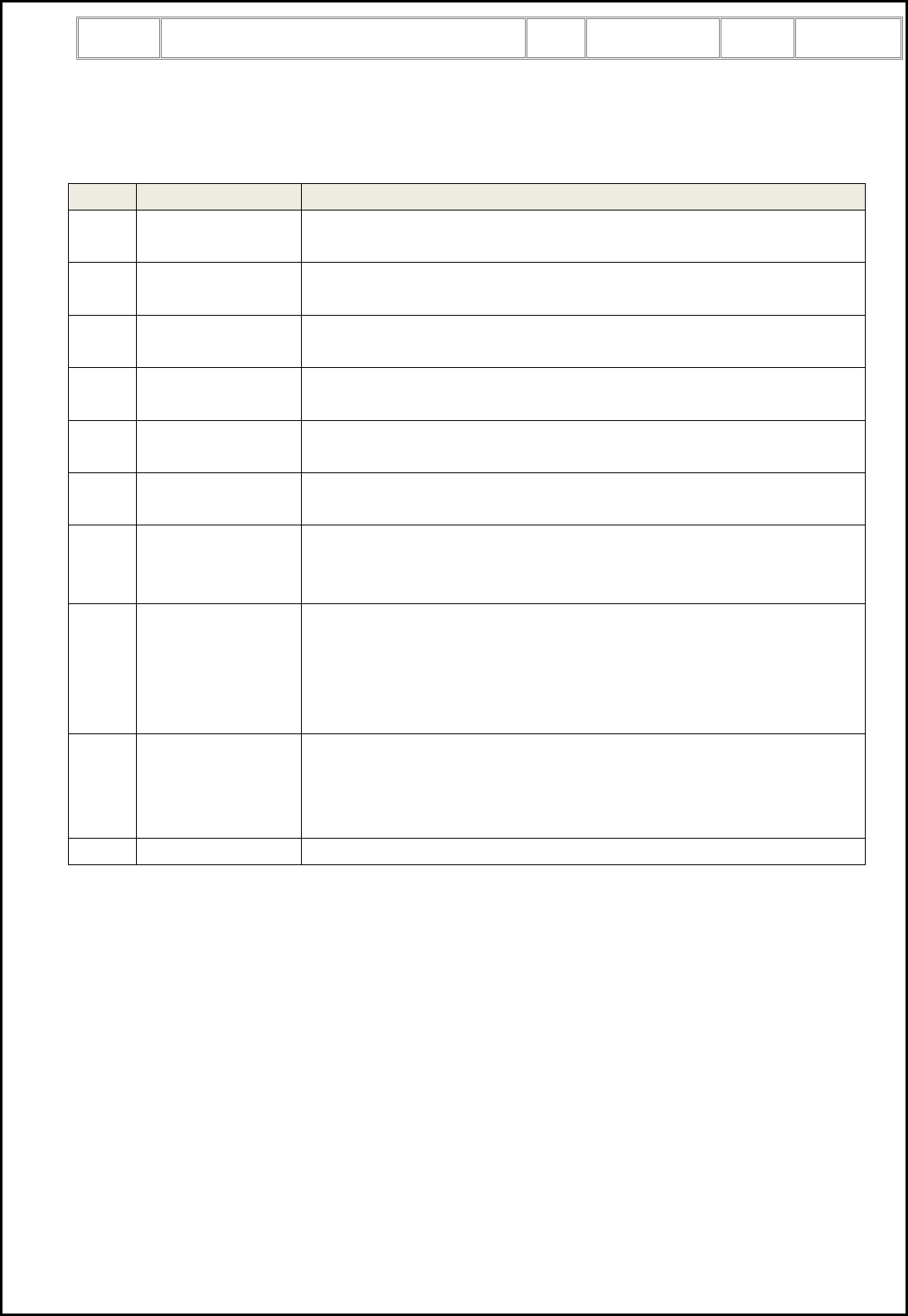
3.1 Front View and Rear View
Figure 1a, front view. Figure 1b, terminal cover opened. Figure 1c, rear view.
1. Optical port
2. Nameplate
3. Terminal cover sealing screws
4. RF antenna interface sealing screw
5. LED indicators
6. Main terminals
7. 3G communication module
8. Auxiliary terminals
9. Device fixing hook
10. Device fixing holes
11. Terminal cover
Title:
AJ102 Data Concentrator Unit User Manual
Ver.
1.4
Page:
8 of 23
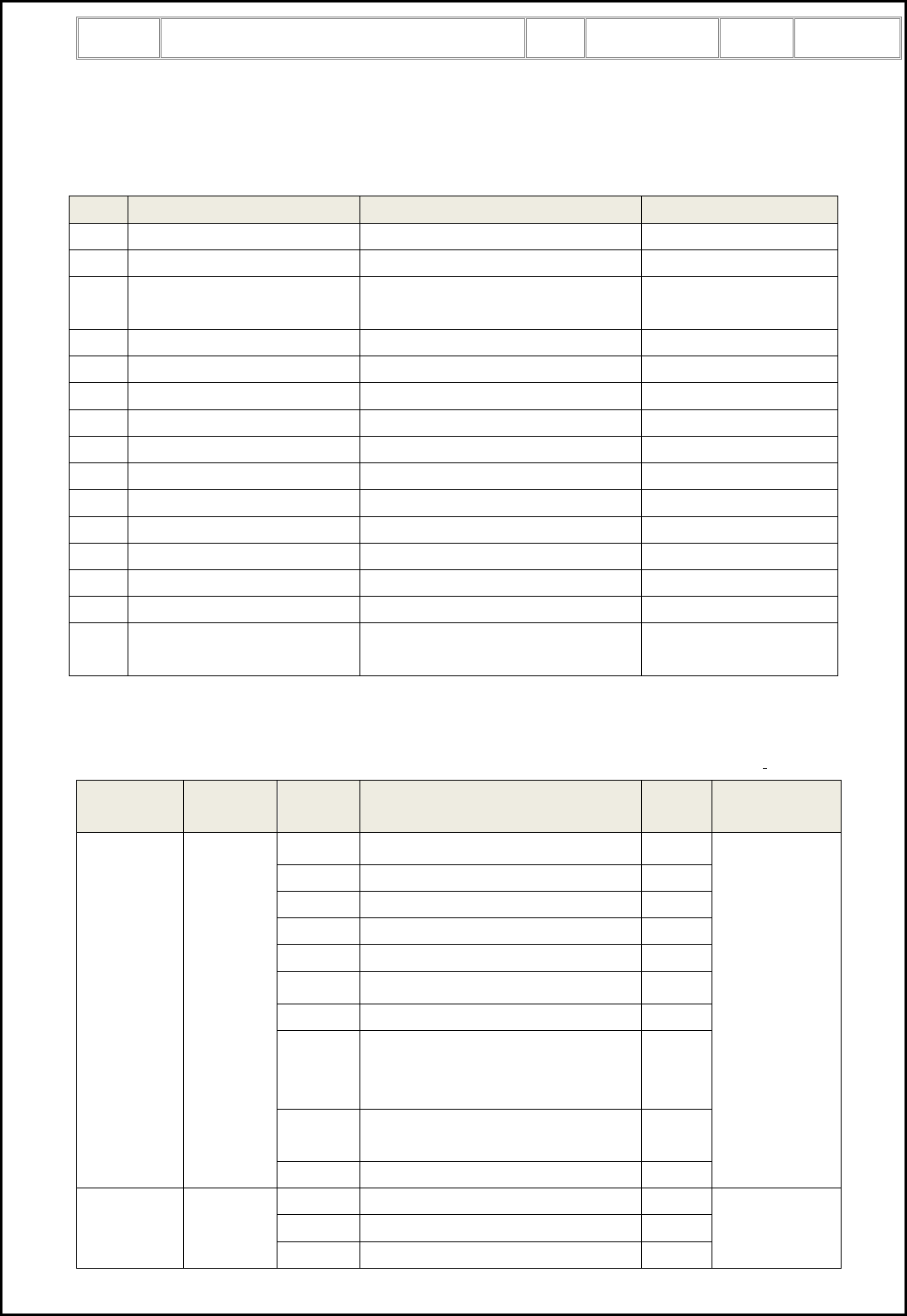
3.2 Technical Features
Feature
Value
Voltage
3×230V/400V (80% to 120%Un)
Frequency
60 Hz (± 5%)
Meter capacity
Not less than 200 smart meters (Daily profile data)
Power consumption
Static power consumption: active ≤ 5W, apparent ≤ 10VA
With communication: active ≤ 10W, apparent ≤ 15VA
Communication protocol
DLMS/COSEM
Display feature
LED indicators
Tamper protection
Terminal cover removal detection
Main cover removal detection
DCU dismantling or removal detection
Communication
interfaces
WAN:
One plug and play 3G module support DLMS/COSEM with TCP/UDP
profile. (UMTS-B1 , UMTS-B5, GSM-900, GSM-1800)
One 10/100M Ethernet port with RJ-45 connector.
LAN:
One Lora RF port, which is embedded in the main board. The basic
parameter as follows:
Frequency:915.25 ~ 917.75 MHz
TX power:≤14±1dbm
RX sensitivity:≤ -119dbm(@SF=8,BW=500KHz,Data rate=12500bps)
6 dB BW:≥500KHz
Local:
One optical port for local communication with 9600bps baud rate,
DLMS/COSEM with direct HDLC profile.
Auxiliaries power supply
N/A
RTC
0.5s/day at reference temperature, comply with IEC 62054-21
Clock backup source: lithium battery
Insulation protection
Class II
Mechanical
Dimensions (mm): 310mm×175mm×86mm
Enclosure material: PC
Environmental
Operating temperature range:+10℃~ +85℃
Storage and transport temperature range: -25℃~ +85℃
Relative humidity up to 95% non-condensing
Title:
AJ102 Data Concentrator Unit User Manual
Ver.
1.4
Page:
9 of 23
4 Function Characteristics
4.1 Clock Management
DCU has a RTC which complies with IEC 62052-21/62054-21. At reference voltage and reference
temperature (23°C), clock accuracy is better than ±0.5 s/day.
The RTC supports leap year, day light saving time. In case of power off, clock of DCU is active for at least
two years after manufactured with battery support.
DCU automatically synchronizes its clock with SNTP server every day.
The central system can synchronize the DCU’s clock.
When the DCU’s clock is invalid, DCU will not automatically collect the data from meters.
4.2 Synchronize Meter Clock
DCU automatically synchronizes the clock of the meters once a day.
DCU interrogates the clock of meters. Depending on the clock difference, DCU take following action:
Clock difference
DCU action
≥10 minutes
Record a clock over limit event for the meter.
≥ 5 minutes
And < 10 minutes
Set the clock of meter
< 5 minutes
No action, the meter’s clock will be synchronized in next day’s clock
synchronization procedure of DCU.
4.3 Node Discovery and Auto-routing
DCU automatically discover the new-installed RF repeater. Automatically routing will be provided by DCU
for RF repeater. DCU supports maximum two levels of RF repeater.
Once DCU discovers new meter, if the meter is not registered in the DCU, DCU will report this meter to
central system, then central system will download the meter archive information into DCU.
4.4 Automatically Meter Data Collection
DCU automatically collects the data from single phase meter, three phase meter with direct connection and
three phase meter with CT connection. The data type for automatically connection includes monthly billing
data, daily profile data, load profile data, and meter event logs. It is configurable to enable or disable the
data collection for each type of data.
4.4.1 Re-collect the Data
In case of missing some data for the meters, DCU will automatically re-collect it from the meters:
Data Type
Re-collection Period
Monthly billing data
Last month

Title:
AJ102 Data Concentrator Unit User Manual
Ver.
1.4
Page:
10 of 23
Daily profile data
Last two days
Energy load profile
Last two days
Power quality load profile
Last two days
4.4.2 Storage Capacity
Below table defines the storage capacity for meter monthly billing data, daily profile data, load profile data
and meter event logs:
Data Type
Capacity
Monthly billing data
13 months
Daily profile data
32 days
Energy load profile
4 days
Power quality load profile
4 days
Event logs
200 events for each meter
The data will be first in first out (FIFO).
4.4.3 Data Upload to Central System
Central system can read the meters’ data stored in DCU through DLMS protocol via the DCU’s WAN
communication port.
The new read data will be compressed in files and sent to the central system by FTP. It is configurable for
the FTP data uploading schedule.
4.5 On Demand Request and Response Transferring
DCU works transparently to get the on request from the central system, and transfer the request to specified
meter, and transfer the response from the meter to the central system. DCU does not interpret the request
and response.
The request to meter includes but not limit to:
1) Read meter energy registers, instant parameters, other registers
2) Read tariff schedule
3) Read clock
4) Set meter parameters, tariff schedule
5) Set tariff schedule
6) Set clock
7) Connect or disconnect the meter
8) Read monthly billing data, daily profile data, load profile data.
4.6 DCU Firmware Upgrade
DCU’s firmware is upgradable from the central system through FTP protocol.
DCU’s firmware is also upgradable from the central system or optical port through DLMS protocol.
4.7 Meter Firmware Upgrade
Central system can request DCU to upgrade the meter’s firmware. DCU will firstly download the meter
firmware from central system via FTP protocol, then start to download the firmware to the meters. The
meter firmware upgrade procedure compliant to the DLMS firmware upgrade procedure.
Title:
AJ102 Data Concentrator Unit User Manual
Ver.
1.4
Page:
11 of 23
4.8 Self-diagnose and Working Status
DCU self-diagnose the communication ports (i.e. 3G module, RF, RS485, optical port etc), clock.
The DCU status word shows the self-diagnostic result and the current working status:
Bit#
Description
Condition to Set
Condition to reset
0
Device power up
DCU is power up
-
1
3G module failure
3G module failure
Recovered from failure
2
3G signal level is too low
3G CSQ less than 11, signal quality
level is too low
3G CSQ is not less than
11
4
RF module failure
RF communication module failure
Recovered from failure
5
NAND flash space full alarm
Flash memory is occupied over 80%
Flash memory is not full.
6
Main cover removal
Main cover is removed
Main cover is closed
7
DCU unlock
DCU is unlock
DCU is locked.
8
Optical port failure
Optical port loop back test failure
Recovered from failure
9
RS-485 failure
RS-485 loop back test failure
Recovered from failure
10
Terminal cover removal
Terminal cover is removed
Terminal cover is closed
11
Clock invalid
Clock is invalid
Clock is set
12
Reserved
13
Reserved
14
Reserved
15
Image download flag
Meter firmware upgrade is in
progress
Meter firmware upgrade
is not running
4.9 Event Logs
The DCU records the following events. It is configurable whether push the event to central system.
Group
Capacity
Code
Description
Push
Capture
Objects
Standard
Event
200
0x0001
Power off
Yes
Event code,
timestamp
0x0002
Power on
Yes
0x0009
System reboot
No
0x0010
Clock is invalid
Yes
0x0017
3G module failure
Yes
0x0019
RF module failure
Yes
0x0032
Parameters is changed
No
0x0057
Input event (SPD detected)
SPD OK: Giving a disconnect signal
SPD Fail: Giving a connect signal
Yes
0x0603
Clock is adjusted since the clock is
over limit (10 minutes)
No
0x0023
Flash memory full (80% used)
Yes
Fraud Event
200
0x011F
Main cover is removed
Yes
Event code,
timestamp
0x0120
Main cover is closed
Yes
0x0121
Terminal cover is removed
Yes
Title:
AJ102 Data Concentrator Unit User Manual
Ver.
1.4
Page:
12 of 23
0x0122
Terminal cover is closed
Yes
Firmware
Upgrade
20
0x0301
DCU firmware upgrade successfully
No
Event code,
timestamp
Communica
tion Event
200
0x0503
Local communication connection
happened
No
Event code,
timestamp
0x0505
Remote communication connection
happened
No
0x0502
Error communication key
Yes
Meter Event
200 for
each meter
0x3201
Meter is unreachable for 72 hours
Yes
Event code,
timestamp
0x3202
Meter is reachable
Yes
0x3203
Meter’s clock is over limit (10
minutes)
Yes
0x3204
Meter’s status word error
Yes
-
All types of meter event pushed by
meter
Yes
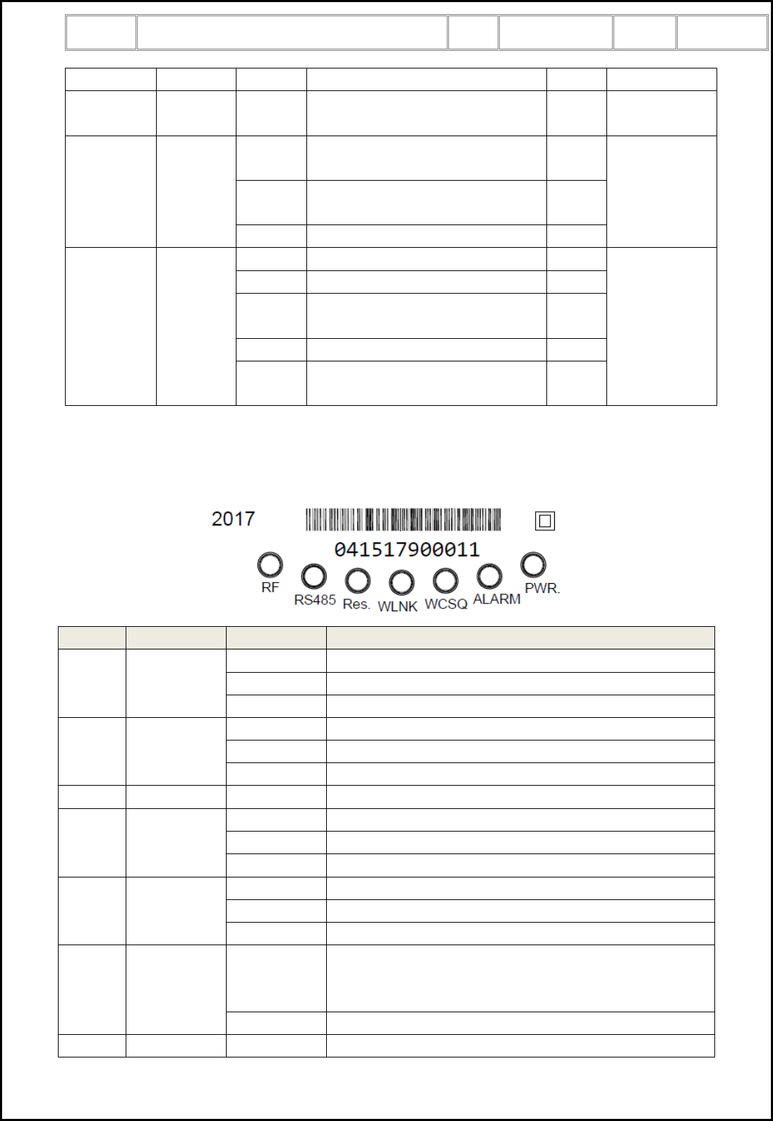
4.10 LED Indicators
DCU has seven LED to indicate the working status.
No.
LED
Status
Description
1
RF
ON
RF module failure
BLINK
Communication with RF repeater is ongoing
OFF
No RF communication
2
RS-485
ON
Indicate RS-485 communication port fail
BLINK
Communication with RS485 meter is ongoing
OFF
No RS-485 communication
3
Res.
-
Reserved
4
WLNK
ON
DCU has connected to HES
BLINK
Communication with HES is ongoing
OFF
No connection to HES
5
WCSQ
ON
3G signal quality is good
BLINK
3G signal quality is weak
OFF
3G signal quality is poor or the channel is not 3G
6
ALARM
ON
Alarm (3G module failure, RF module failure, optical port
failure, RS-485 port failure, main cover clock invalid) is
detected in DCU
OFF
No alarm
7
PWR.
ON
Always on when power supply is ok
Title:
AJ102 Data Concentrator Unit User Manual
Ver.
1.4
Page:
13 of 23
5 Communication Interfaces
The DCU provides following communication interfaces:
Function
Interface
Baud Rate
Protocol
Local
Optical port
9,600 bps
DLMS/COSEM HDLC profile
RS-232
115,200 bps
WAN
3G
Downlink transfer: max. 85.6 kbps
Uplink transfer: 42.9 kbps
DLMS/COSEM TCP/IP Profile.
RJ-45 Ethernet
10/100M
DLMS/COSEM TCP/IP Profile.
AN
RF
1,700 bps
DLMS/COSEM HDLC profile
RS-485
4,800 bps
DLMS/COSEM HDLC profile
5.1 Optical Port Communication
The optical port is used to read DCU and configure the DCU parameter or control the DCU locally. In
general, PC software is used to communicate with DCU via this optical port.
5.2 WAN Communication
The DCU has one replaceable 3G module as the main WAN communication interface, and has an Ethernet
communication interface as a backup WAN communication interface.
5.2.1 3G Communication
Remote communication uses 3G, and bases on DLMS/COSEM TCP/IP profile. The key features of 3G are
listed in below table:
General
Function
Performance &
Availability
Class 12 3G communication slot.
Support reconnection behavior after detecting an unexpected interrupted
communication session.
SIM
Support 2FF SIM card.
Support IMEI lock of the USIM card.
Indications of 3G
signal strength
Indicate 3G signal strength in a minimum of 3 separate levels. Refer to LED
indicators.
RSSI value is readable.
Antenna
Support both internal antenna and external antenna. Exchange the antenna
without de-energizing the device.
Access and
connection
Wake-up
Support fully qualified domain names.
Receive and store the IP addresses of the primary and secondary address
when establishing a PDP context based on the DHCP protocol
Support data pushing.
Authentication
and security
Changeable APN/password
Support RADIUS authentication using PAP or CHAP.
Network access information is not saved on the SIM cards
Communication settings to be remotely configurable
Assign IP
address
3G module support dynamic IP address assignment

Title:
AJ102 Data Concentrator Unit User Manual
Ver.
1.4
Page:
14 of 23
The 3G communication parameters are generally programmed in the factory. It is also possible to change
the communication parameter remotely or locally.
Refer to LED indicators chapter for the communication status indication.
5.2.2 Ethernet Communication
DCU supports one Ethernet port which can also be used for remote communication.
5.3 LAN Communication
DCU supports three LAN communication interfaces:
1) A RF communication interface which is embedded on the main board.
2) A RS-485 communication interface.
5.3.1 RF Communication
RF communication is based on DLMS/COSEM HDLC profile. The key features of RF are listed below:
Communication frequency: 915.25M , 915.85M, 916.60M, 917.10M, 917.75M
Auto-repeater, network self-healing
Meter auto-registration
Up to two repeater levels
Refer to LED indicators chapter for the RF communication status indication.
5.3.2 RS-485 Communication
DCU has one RS-485 communication port, which can be used to connect to RS-485 meters. The interface
supports DLMS/COSEM HDLC profile.
Title:
AJ102 Data Concentrator Unit User Manual
Ver.
1.4
Page:
15 of 23
6 Security
6.1 Physical Security
The DCU has two seals for the terminal cover, one seal for the RF antenna box. It is impossible to access
the DCU internal part unless physically and transparently destroy the seals and the DCU face or terminal
cover. The DCU records the main cover removal event and terminal cover removal event in both power on
condition and power off condition.
The DCU detects the meter dismantle/removal event.
6.2 Communication Security
The DCU supports state-of-art security for data access and data transportation basing on a role-based
security. Each role has its own access privileges. Here below table lists all the roles, their privileges,
security mechanism:
Role
Client ID
Privileges
Security Mechanism
Public
16
Read limited DCU information, like the DCU serial
number.
No
Read-Only
2
Read DCU
LLS Mechanism id 1
Read-Write
1
Read DCU, configure DCU parameters
HLS Mechanism id 2
6.3 Keys of DCU
The DCU has the following keys for each DLMS HLS client.
No
Type Name
Description
1
Authentication key
Ensure data integrity and authenticity
2
Encryption key
Ensure data confidentiality
3
Master key
Use to change other keys
Each DCU has its own individual keys once out of factory.
All the keys are updatable from central system.
6.4 Communication Security to Meters
DCU follows smart meter’s security policy. All communication to meters are authenticated and encrypted.
Title:
AJ102 Data Concentrator Unit User Manual
Ver.
1.4
Page:
16 of 23
7 Transportation and Storage
The DCU should be placed on pallet and the height should not exceed 5 layers. The storage condition
should be clean, with an environmental temperature of between -25°C and +85°C, relative humidity of less
than 95% and with an absence of rusty matter in the air.
8 DCU Installation
8.1 Installation Environment
DCU should be installed at a dry and well-ventilated place. The installation board should be fixed on a solid,
fire-resistant and sturdy wall. The suggested installation height is about 1.8 meters.
8.2 Dimension and Weight
The dimension of DCU is 310mm×175mm×86mm (L×W×H), and weight is 1.2kg.
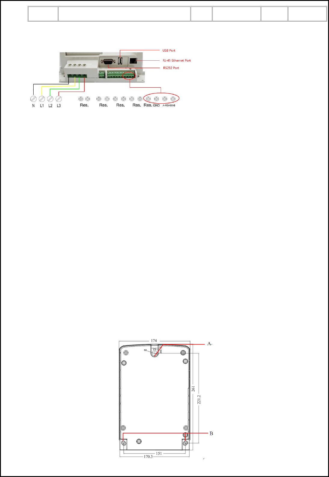
8.3 Wiring Diagram and Auxiliary Terminals
The wiring diagram and auxiliary terminals of DCU:
Title:
AJ102 Data Concentrator Unit User Manual
Ver.
1.4
Page:
17 of 23
8.4 Installation Guide
8.4.1 What You Need
To install DCU, you should prepare:
Screw driver: FD3 screw driver for main terminal screw.
Fixing screw and Hook screw: M5 slotted countersunk (flat) head tapping screw.
Electric drill with M3 broach for metal meter box installation.
Electric drill with M5 broach and plastic plug for concrete wall installation.
8.4.2 DCU Installation
Cut off the power supply to where the DCU will be installed, this is the most important thing!!!
Step 1: Inspect DCU before installation
Before installation, please make sure there is no damage, broken or other defect on DCU.
If defect is found, please don’t install the DCU.
Step 2: Fixing
DCU is 3-point mounting system, fixed by 1 hook and 2 fixing screws.
To fix DCU, hang the DCU by hook then fasten two fixing screws.
Title:
AJ102 Data Concentrator Unit User Manual
Ver.
1.4
Page:
18 of 23
A: Hook, B: Fixing hole
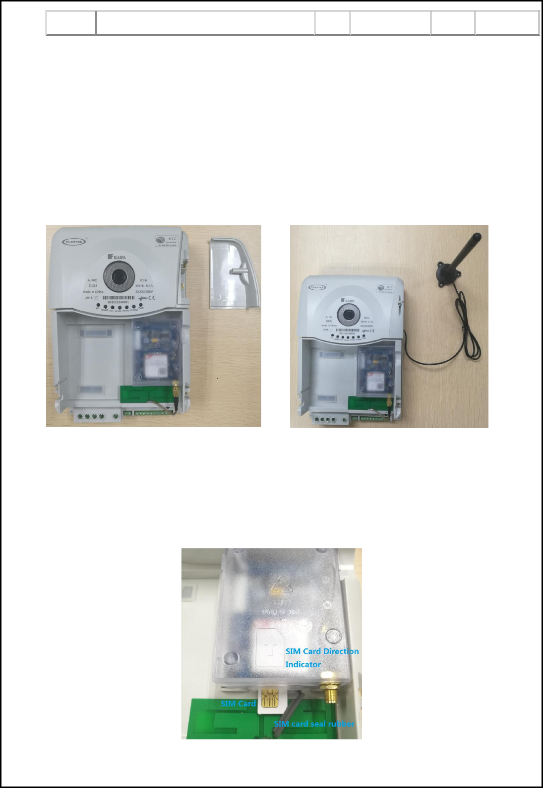
Step 3: Install RF antenna
1) Remove the RF antenna cover
2) Connect tightly the RF antenna to the RF antenna connector
3) Remove the cut-out of the RF antenna cover
4) Install the RF antenna cover, the RF antenna cable should pass through the cut-out
5) Fix the screw
6) Seal the RF antenna cover.
Note: Before install the RF antenna, you may need to fix the RF antenna on the cabinet of the DCU. Make
sure the RF antenna is fixed in the top right direction, and Antenna location according to actual can be
installed at the scene of the adjustment.
Step 4: Install 3G SIM card (2FF SIM card)
1) Open the SIM card seal rubber.
2) Insert the SIM card into the slot with right direction, and make sure the SIM card is installed rightly.
3) Close the SIM card seal rubber, and make sure the slot is totally sealed.
Note: It’s better to install the SIM card without removing the 3G module from the DCU. It is important to
seal the slot with the rubber completely.
Title:
AJ102 Data Concentrator Unit User Manual
Ver.
1.4
Page:
19 of 23
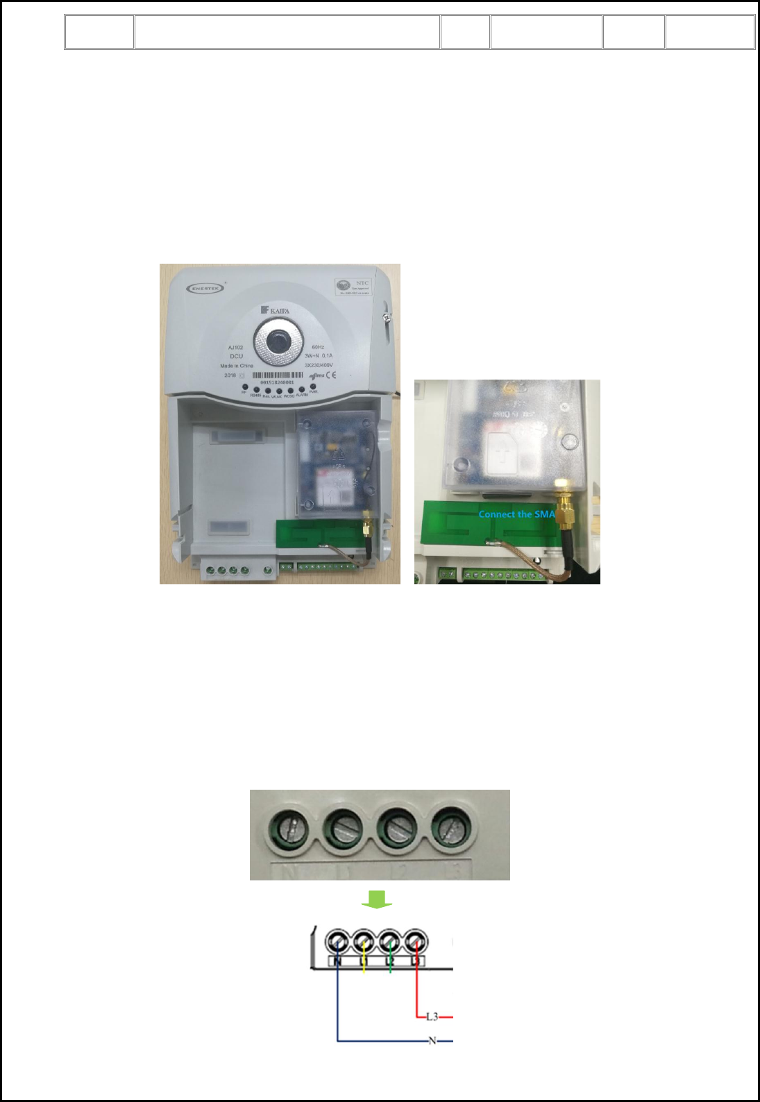
Step 5: Install 3G external antenna
Tightly connect the external 3G antenna to SMA connector on the 3G module.
Note:
1) It’s better to install 3G antenna without removing the 3G module from the DCU.
2) Before install the 3G antenna, you may need to fix the 3G antenna on the cabinet of the DCU. Make
sure the 3G antenna is fixed at the bottom of the 3G module, and as show in figure shows are as
follows.(The antenna has been fixed on the bottom of the 3G module with 3m glue)
3) After installed the SIM card and 3G antenna, please check if the 3G module is tightly connected to the
main box of DCU.
Step 6: Connect the power wires
Connect the power wires according to the marking on the terminals.
Note:
1) To insure the reliable connection, install torque must higher than 3.5Nm.
2) The wire sequence from left to right be neutral, L1, L2, L3. It is important to have a right phase
sequence. Single-phase power supply is recommended to connect neutral and L3.
3) It is proposed to install a fuse-controlled disconnect switch before the DCU, so that it is easy to power
off the DCU for any maintain purpose.

Title:
AJ102 Data Concentrator Unit User Manual
Ver.
1.4
Page:
20 of 23
Step 7: Power on inspection
After right connection of power wires, turn on the power. Inspect LED status according to chapter 4.10.
1) “PWR” LED should be on.
2) “WCSQ” LED should be on, or at least blink.
3) “Res.” LED should not be always on.
4) “RF” LED should not be always on.
5) “ALARM” LED should not be on.
If “WCSQ” LED is off, it means 3G signal quality is very low, please try to adjust the position the 3G
external antenna. If “WCSQ” is still off, there will be no connection the 3G.
If “ALARM” LED is on, it means there is some failures on DCU. Please contact the expert or replace to
install a new DCU.
If the 3G parameter (APN, user, and password etc.) and HES parameter (server IP, port no etc.) is
configured before the installation, the DCU will try to dial 3G and connect to the HES. After successfully
connect to HES, the “WLNK” LED will be on or blink.
Note: before power on DCU, please make sure 3G module is tightly connected to the DCU box.
Step 8: Configure the communication parameters (This step is needed only if DCU is not rightly configured
before installation)
Use configuration software to configure the right 3G communication parameters (APN, user name,
password etc.), and HES communication parameters (server IP, port no etc.). Use configuration software to
send a reboot command to reboot DCU. After reboot is finished, DCU tries to connect to HES. After
successfully connect to HES, the “WLNK” LED will be on or blink.
Note: It is strongly proposed to configure the DCU communication parameters before installation of DCU.
Step 9: Install the terminal cover
1) Install the terminal cover tightly
2) Fix the terminal screws
3) Seal the terminal cover screws.
The installation of DCU is finished.
Note :The detail installation guide in the box refers to “Meter and Meter Box Installation
Specification.pdf”.
Title:
AJ102 Data Concentrator Unit User Manual
Ver.
1.4
Page:
21 of 23
Annex 1 Reference Standards
No.
Standard No.
Title
1
IEC 62056-21 Ed.
1.0:2002
Electricity metering – Data exchange for meter reading, tariff and load control
– Part 21: Direct local data exchange
2
IEC 62056-46 Ed.
1.1:2007
Electricity metering – Data exchange for meter reading, tariff and load control
– Part 46: Data link layer using HDLC protocol
3
IEC 62056-53 Ed.
2.0:2006
Electricity metering – Data exchange for meter reading, tariff and load control
– Part 53: COSEM Application layer
4
IEC 62056-61 Ed.
2.0:2006
Electricity metering – Data exchange for meter reading, tariff and load control
– Part 61: Object identification system (OBIS)
5
IEC 62056-62 Ed.
2.0:2006
Electricity metering – Data exchange for meter reading, tariff and load control
– Part 62: Interface classes
6
ETSI EN301 511
V9.0.2(2003-03)
7
ETSI EN301 489-1
V1.9.2(2011-09)
Electromagnetic compatibility and Radio spectrum Matters(ERM);
Electromagnetic Compatibility (EMC) standard for radio equipment and
services; Part 1: Common technical requirements
8
ETSI EN301 489-7
V1.3.1(2005-11)
Electromagnetic compatibility and Radio spectrum Matters (ERM);
Electromagnetic Compatibility (EMC) standard for radio equipment and
services; Part 7: Specific conditions for mobile and portable radio and
ancillary equipment of digital cellular radio telecommunications systems
(GSM and DCS)
9
EN 60950-1:2006
+A11:2009
+A1: 2010
+A12:2011
10
EN 62311:2008
Title:
AJ102 Data Concentrator Unit User Manual
Ver.
1.4
Page:
22 of 23
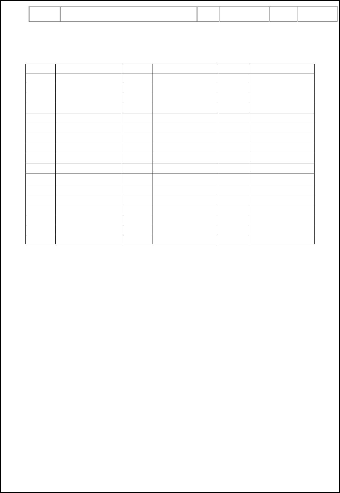
Annex 2 RF communication channel
Channel
Frequency(MHz)
Channel
Frequency(MHz)
Channel
Frequency(MHz)
1
915.25
18
916.10
35
916.95
2
915.30
19
916.15
36
917.00
3
915.35
20
916.20
37
917.05
4
915.40
21
916.25
38
917.10
5
915.45
22
916.30
39
917.15
6
915.50
23
916.35
40
917.20
7
915.55
24
916.40
41
917.25
8
915.60
25
916.45
42
917.30
9
915.65
26
916.50
43
917.35
10
915.70
27
916.55
44
917.40
11
915.75
28
916.60
45
917.45
12
915.80
29
916.65
46
917.50
13
915.85
30
916.70
47
917.55
14
915.90
31
916.75
48
917.60
15
915.95
32
916.80
49
917.65
16
916.00
33
916.85
50
917.70
17
916.05
34
916.90
51
917.75

Title:
AJ102 Data Concentrator Unit User Manual
Ver.
1.1
Page:
1 of 23