Lincoln Electric Ln 25 Svm179 B Users Manual
SVM179-B to the manual d5017ebe-c823-4357-aa08-e055c430acd8
2015-02-09
: Lincoln-Electric Lincoln-Electric-Ln-25-Svm179-B-Users-Manual-574286 lincoln-electric-ln-25-svm179-b-users-manual-574286 lincoln-electric pdf
Open the PDF directly: View PDF ![]() .
.
Page Count: 103 [warning: Documents this large are best viewed by clicking the View PDF Link!]
- Master Table of Contents
- Safety
- Section A - Installation
- Section B - Operation
- Section C - Accessories
- Section D - Maintenance
- Section E - Theory of Operation
- Section F - Troubleshooting and Repair
- Symptoms
- The feeder does not power up - no display (Digital Models) - no cold feed.
- The wire feeder powers up but there is no welder output when the gun trigger is pulled. The shielding gas flows and the drive rolls turn. (Across the arc models)
- Inconsistent wire feeding or wire not feeding but the drive rolls are turning.
- Wire feed speed consistently operates at the wrong value. The speed changes when the control knob is adjusted.
- This wire feeds but cannot be controlled with the wire speed pot.
- Variable or “hunting” arc.
- When the trigger is pulled, the wirefeeds slowly. (Digital display models)
- The preset voltage does not match the power source voltage. (Digital display models)
- Poor arc starts with sticking or “Blast-offs”, weld porosity, narrow or ropy looking beads.
- No shielding gas.
- Section G - Electrical Diagrams
LN-25™PRO WIRE FEEDER
,/&
April, 2011
For use with machines having Code Numbers:
,+/"&'.%
• Sales and Service through Subsidiaries and Distributors Worldwide •
Cleveland, Ohio 44117-1199 U.S.A. TEL: 216.481.8100 FAX: 216.486.1751 WEB SITE: www.lincolnelectric.com
• World's Leader in Welding and Cutting Products •
Copyright © Lincoln Global Inc.
Safety Depends on You
Lincoln arc welding and cutting
equipment is designed and built
with safety in mind. However,
your overall safety can be
increased by proper installation
... and thoughtful operation on
your part. DO NOT INSTALL,
OPERATE OR REPAIR THIS
EQUIPMENT WITHOUT
READING THIS MANUAL
AND THE SAFETY PRE-
CAUTIONS CONTAINED
THROUGHOUT. And, most
importantly, think before you act
and be careful.
Return to Master TOC Return to Master TOC Return to Master TOC Return to Master TOC
View Safety Info View Safety Info View Safety Info View Safety Info
RETURN TO MAIN MENU
%'S)+(
,-2
< <
(+' "'
CBJ8E878DH<C@8AG
1.a. Turn the engine off before troubleshooting and maintenance
work unless the maintenance work requires it to be running.
____________________________________________________
1.b.Operate engines in open, well-ventilated
areas or vent the engine exhaust fumes
outdoors.
____________________________________________________
1.c. Do not add the fuel near an open flame weld-
ing arc or when the engine is running. Stop
the engine and allow it to cool before refuel-
ing to prevent spilled fuel from vaporizing on
contact with hot engine parts and igniting. Do
not spill fuel when filling tank. If fuel is spilled,
wipe it up and do not start engine until fumes
have been eliminated.
____________________________________________________
1.d. Keep all equipment safety guards, covers and devices in posi-
tion and in good repair.Keep hands, hair, clothing and tools
away from V-belts, gears, fans and all other moving parts
when starting, operating or repairing equipment.
____________________________________________________
1.e. In some cases it may be necessary to remove safety
guards to perform required maintenance. Remove
guards only when necessary and replace them when the
maintenance requiring their removal is complete.
Always use the greatest care when working near moving
parts.
___________________________________________________
1.f. Do not put your hands near the engine fan.
Do not attempt to override the governor or
idler by pushing on the throttle control rods
while the engine is running.
___________________________________________________
1.g. To prevent accidentally starting gasoline engines while
turning the engine or welding generator during maintenance
work, disconnect the spark plug wires, distributor cap or
magneto wire as appropriate.
+0%"' 64A58;4M4E7BHF)+(--2(.+,%'(-!+,+(&)(,,"%,+"(.,"'#.+2(+-!
$)!"%+'02)&$+0++,,!(.%(',.%-0"-!-!"+(-(+(+()+-"'
Read and understand the following safety highlights. For additional safety information, it is strongly recommended that you
purchase a copy of “Safety in Welding & Cutting - ANSI Standard Z49.1” from the American Welding Society, P.O. Box 351040,
Miami, Florida 33135 or CSA Standard W117.2-1974. A Free copy of “Arc Welding Safety” booklet E205 is available from the
Lincoln Electric Company, 22801 St. Clair Avenue, Cleveland, Ohio 44117-1199.
,.+ -!-%% "',-%%-"(' ()+-"(' &"'-'' ' +)"+ )+(.+, +
)+(+&('%22*.%"""'"/".%,
0+'"'
%-+"'
& '-""%,
@4L5874A:8EBHF
2.a. Electric current flowing through any conductor causes
localized Electric and Magnetic Fields (EMF). Welding
current creates EMF fields around welding cables and
welding machines
2.b. EMF fields may interfere with some pacemakers, and
welders having a pacemaker should consult their physician
before welding.
2.c. Exposure to EMF fields in welding may have other health
effects which are now not known.
2.d. All welders should use the following procedures in order to
minimize exposure to EMF fields from the welding circuit:
2.d.1.
Route the electrode and work cables together - Secure
them with tape when possible.
2.d.2. Never coil the electrode lead around your body.
2.d.3. Do not place your body between the electrode and
work cables. If the electrode cable is on your right
side, the work cable should also be on your right side.
2.d.4. Connect the work cable to the workpiece as close as
possible to the area being welded.
2.d.5. Do not work next to welding power source.
1.h. To avoid scalding, do not remove the
radiator pressure cap when the engine is
hot.
%"(+'")+()(,"-"('0+'"' ,
Diesel engine exhaust and some of its constituents
are known to the State of California to cause can-
cer, birth defects, and other reproductive harm.
The engine exhaust from this product contains
chemicals known to the State of California to cause
cancer, birth defects, or other reproductive harm.
The Above For Diesel Engines The Above For Gasoline Engines
Return to Master TOC Return to Master TOC Return to Master TOC Return to Master TOC
,-2
<< <<
%'S)+(
.&,' ,,
64A5874A:8EBHF
5.a. Welding may produce fumes and gases
hazardous to health. Avoid breathing these
fumes and gases.When welding, keep
your head out of the fume. Use enough
ventilation and/or exhaust at the arc to keep
fumes and gases away from the breathing zone. 0;8A
J8?7<A: J<G; 8?86GEB78F J;<6; E8DH<E8 FC86<4?
I8AG<?4G<BA FH6; 4F FG4<A?8FF BE ;4E7 946<A: F88
<AFGEH6G<BAF BA 6BAG4<A8E BE &,, BE BA ?847 BE
647@<H@ C?4G87 FG88? 4A7 BG;8E @8G4?F BE 6B4G<A:F
J;<6; CEB7H68 ;<:;?L GBK<6 9H@8F >88C 8KCBFHE8 4F
?BJ 4F CBFF<5?8 4A7 J<G;<A 4CC?<645?8 (,! )% 4A7
"!-%/?<@<GFHF<A:?B64?8K;4HFGBE@86;4A<64?I8A
G<?4G<BA "A 6BA9<A87 FC468F BE <A FB@8 6<E6H@FG4A68F
BHG7BBEF 4 E8FC<E4GBE @4L 58 E8DH<E8777<G<BA4? CE8
64HG<BAF4E84?FB E8DH<E87J;8AJ8?7<A:BA:4?I4A<M87
FG88?
5. b. The operation of welding fume control equipment is affected
by various factors including proper use and positioning of the
equipment, maintenance of the equipment and the specific
welding procedure and application involved. Worker expo-
sure level should be checked upon installation and periodi-
cally thereafter to be certain it is within applicable OSHA PEL
and ACGIH TLV limits.
5.c.
Do not weld in locations near chlorinated hydrocarbon
vapors
coming from degreasing, cleaning or spraying operations.
The heat and rays of the arc can react with solvent vapors
to
form phosgene, a highly toxic gas, and other irritating prod-
ucts.
5.d. Shielding gases used for arc welding can displace air and
cause injury or death. Always use enough ventilation,
especially in confined areas, to insure breathing air is safe.
5.e. Read and understand the manufacturer’s instructions for this
equipment and the consumables to be used, including the
material safety data sheet (MSDS) and follow your
employer’s safety practices. MSDS forms are available from
your welding distributor or from the manufacturer.
5.f. Also see item 1.b.
++2,64A5HEA
4.a. Use a shield with the proper filter and cover
plates to protect your eyes from sparks and
the rays of the arc when welding or observing
open arc welding. Headshield and filter lens
should conform to ANSI Z87. I standards.
4.b. Use suitable clothing made from durable flame-resistant
material to protect your skin and that of your helpers from
the arc rays.
4.c. Protect other nearby personnel with suitable, non-flammable
screening and/or warn them not to watch the arc nor expose
themselves to the arc rays or to hot spatter or metal.
%-+",!($64A><??
3.a. The electrode and work (or ground) circuits
are electrically “hot” when the welder is on.
Do not touch these “hot” parts with your bare
skin or wet clothing. Wear dry, hole-free
gloves to insulate hands.
3.b. Insulate yourself from work and ground using dry insulation.
Make certain the insulation is large enough to cover your full
area of physical contact with work and ground.
"A477<G<BAGBG;8ABE@4?F498GLCE864HG<BAF<9J8?7<A:
@HFG 58 C8E9BE@87 HA78E 8?86GE<64??L ;4M4E7BHF
6BA7<G<BAF <A 74@C ?B64G<BAF BE J;<?8 J84E<A: J8G
6?BG;<A:BA@8G4?FGEH6GHE8FFH6;4F9?BBEF:E4G<A:FBE
F6499B?7F J;8A <A 6E4@C87 CBF<G<BAF FH6; 4F F<GG<A:
>A88?<A:BE?L<A:<9G;8E8<F4;<:;E<F>B9HA4IB<745?8BE
466<78AG4? 6BAG46G J<G; G;8 JBE>C<868 BE :EBHA7 HF8
G;89B??BJ<A:8DH<C@8AG
R,8@<4HGB@4G<6BAFG4AG/B?G4:80<E808?78E
R&4AH4?,G<6>08?78E
R08?78EJ<G;+87H687/B?G4:8BAGEB?
3.c. In semiautomatic or automatic wire welding, the electrode,
electrode reel, welding head, nozzle or semiautomatic
welding gun are also electrically “hot”.
3.d. Always be sure the work cable makes a good electrical
connection with the metal being welded. The connection
should be as close as possible to the area being welded.
3.e. Ground the work or metal to be welded to a good electrical
(earth) ground.
3.f.
Maintain the electrode holder, work clamp, welding cable and
welding machine in good, safe operating condition. Replace
damaged insulation.
3.g. Never dip the electrode in water for cooling.
3.h. Never simultaneously touch electrically “hot” parts of
electrode holders connected to two welders because voltage
between the two can be the total of the open circuit voltage
of both welders.
3.i. When working above floor level, use a safety belt to protect
yourself from a fall should you get a shock.
3.j. Also see Items 6.c. and 8.
Return to Master TOC Return to Master TOC Return to Master TOC Return to Master TOC
%'S)+(
,-2
<<< <<<
(+%-+"%%2
CBJ8E878DH<C@8AG
8.a. Turn off input power using the disconnect
switch at the fuse box before working on
the equipment.
8.b. Install equipment in accordance with the U.S. National
Electrical Code, all local codes and the manufacturer’s
recommendations.
8.c. Ground the equipment in accordance with the U.S. National
Electrical Code and the manufacturer’s recommendations.
2%"'+@4L8KC?B78
<974@4:87
7.a. Use only compressed gas cylinders
containing the correct shielding gas for the
process used and properly operating
regulators designed for the gas and
pressure used. All hoses, fittings, etc. should be suitable for
the application and maintained in good condition.
7.b. Always keep cylinders in an upright position securely
chained to an undercarriage or fixed support.
7.c. Cylinders should be located:
• Away from areas where they may be struck or subjected to
physical damage.
• A safe distance from arc welding or cutting operations and
any other source of heat, sparks, or flame.
7.d. Never allow the electrode, electrode holder or any other
electrically “hot” parts to touch a cylinder.
7.e. Keep your head and face away from the cylinder valve outlet
when opening the cylinder valve.
7.f. Valve protection caps should always be in place and hand
tight except when the cylinder is in use or connected for
use.
7.g. Read and follow the instructions on compressed gas
cylinders, associated equipment, and CGA publication P-l,
“Precautions for Safe Handling of Compressed Gases in
Cylinders,” available from the Compressed Gas Association
1235 Jefferson Davis Highway, Arlington, VA 22202.
0%"' 4A7 .--"'
,)+$,64A64HF89<E8BE
8KC?BF<BA
6.a.
Remove fire hazards from the welding area.
If
this is not possible, cover them to prevent the welding sparks
from starting a fire. Remember that welding sparks and hot
materials from welding can easily go through small cracks
and openings to adjcent areas. Avoid welding near hydraulic
lines. Have a fire extinguisher readily available.
6.b. Where compressed gases are to be used at the job site,
special precautions should be used to prevent hazardous
situations. Refer to “Safety in Welding and Cutting” (ANSI
Standard Z49.1) and the operating information for the
equipment being used.
6.c. When not welding, make certain no part of the electrode
circuit is touching the work or ground. Accidental contact can
cause overheating and create a fire hazard.
6.d. Do not heat, cut or weld tanks, drums or containers until the
proper steps have been taken to insure that such procedures
will not cause flammable or toxic vapors from substances
inside. They can cause an explosion even
though
they have
been “cleaned”. For information, purchase “Recommended
Safe Practices for the
Preparation
for Welding and Cutting of
Containers and Piping That Have Held Hazardous
Substances”, AWS F4.1 from the American Welding Society
(see address above).
6.e. Vent hollow castings or containers before heating, cutting or
welding. They may explode.
6.f.
Sparks and spatter are thrown from the welding arc. Wear oil
free protective garments such as leather gloves, heavy shirt,
cuffless trousers, high shoes and a cap over your hair. Wear
ear plugs when welding out of position or in confined places.
Always wear safety glasses with side shields when in a
welding area.
6.g. Connect the work cable to the work as close to the welding
area as practical. Work cables connected to the building
framework or other locations away from the welding area
increase the possibility of the welding current passing through
lifting chains, crane cables or other alternate circuits. This can
create fire hazards or overheat lifting chains or cables until
they fail.
6.h. Also see item 1.c.
6.I. Read and follow NFPA 51B “ Standard for Fire Prevention
During Welding, Cutting and Other Hot Work”, available from
NFPA 1 Batterymarch Park,PO box 9101, Quincy, Ma
022690-9101.
6.j. Do not use a welding power source for pipe thawing.
Refer to ;GGCJJJ?<A6B?A8?86GE<66B@F498GL for additional safety information.
Return to Master TOC Return to Master TOC Return to Master TOC Return to Master TOC

,-2
<I <I
%'S)+(
)+N.-"(',,Y+-N
Pour votre propre protection lire et observer toutes les instructions
et les précautions de sûreté specifiques qui parraissent dans ce
manuel aussi bien que les précautions de sûreté générales suiv-
antes:
,PE8GO)BHE,BH74:8%[E6
1. Protegez-vous contre la secousse électrique:
a. Les circuits à l’électrode et à la piéce sont sous tension
quand la machine à souder est en marche. Eviter toujours
tout contact entre les parties sous tension et la peau nue
ou les vétements mouillés. Porter des gants secs et sans
trous pour isoler les mains.
b. Faire trés attention de bien s’isoler de la masse quand on
soude dans des endroits humides, ou sur un plancher met-
allique ou des grilles metalliques, principalement dans
les positions assis ou couché pour lesquelles une grande
partie du corps peut être en contact avec la masse.
c. Maintenir le porte-électrode, la pince de masse, le câble de
soudage et la machine à souder en bon et sûr état defonc-
tionnement.
d.Ne jamais plonger le porte-électrode dans l’eau pour le
refroidir.
e. Ne jamais toucher simultanément les parties sous tension
des porte-électrodes connectés à deux machines à souder
parce que la tension entre les deux pinces peut être le total
de la tension à vide des deux machines.
f. Si on utilise la machine à souder comme une source de
courant pour soudage semi-automatique, ces precautions
pour le porte-électrode s’applicuent aussi au pistolet de
soudage.
2. Dans le cas de travail au dessus du niveau du sol, se protéger
contre les chutes dans le cas ou on recoit un choc. Ne jamais
enrouler le câble-électrode autour de n’importe quelle partie du
corps.
3. Un coup d’arc peut être plus sévère qu’un coup de soliel, donc:
a. Utiliser un bon masque avec un verre filtrant approprié ainsi
qu’un verre blanc afin de se protéger les yeux du rayon-
nement de l’arc et des projections quand on soude ou
quand on regarde l’arc.
b. Porter des vêtements convenables afin de protéger la peau
de soudeur et des aides contre le rayonnement de l‘arc.
c. Protéger l’autre personnel travaillant à proximité au
soudage à l’aide d’écrans appropriés et non-inflammables.
4. Des gouttes de laitier en fusion sont émises de l’arc de
soudage. Se protéger avec des vêtements de protection libres
de l’huile, tels que les gants en cuir, chemise épaisse, pan-
talons sans revers, et chaussures montantes.
5. Toujours porter des lunettes de sécurité dans la zone de
soudage. Utiliser des lunettes avec écrans lateraux dans les
zones où l’on pique le laitier.
6. Eloigner les matériaux inflammables ou les recouvrir afin de
prévenir tout risque d’incendie dû aux étincelles.
7. Quand on ne soude pas, poser la pince à une endroit isolé de
la masse. Un court-circuit accidental peut provoquer un
échauffement et un risque d’incendie.
8. S’assurer que la masse est connectée le plus prés possible de
la zone de travail qu’il est pratique de le faire. Si on place la
masse sur la charpente de la construction ou d’autres endroits
éloignés de la zone de travail, on augmente le risque de voir
passer le courant de soudage par les chaines de levage,
câbles de grue, ou autres circuits. Cela peut provoquer des
risques d’incendie ou d’echauffement des chaines et des
câbles jusqu’à ce qu’ils se rompent.
9. Assurer une ventilation suffisante dans la zone de soudage.
Ceci est particuliérement important pour le soudage de tôles
galvanisées plombées, ou cadmiées ou tout autre métal qui
produit des fumeés toxiques.
10. Ne pas souder en présence de vapeurs de chlore provenant
d’opérations de dégraissage, nettoyage ou pistolage. La
chaleur ou les rayons de l’arc peuvent réagir avec les vapeurs
du solvant pour produire du phosgéne (gas fortement toxique)
ou autres produits irritants.
11. Pour obtenir de plus amples renseignements sur la sûreté, voir
le code “Code for safety in welding and cutting” CSA Standard
W 117.2-1974.
)+N.-"(',,Y+-N)(.+
%,&!"',U,(.+U
-+',(+&-.+-U
++,,.+
1. Relier à la terre le chassis du poste conformement au code de
l’électricité et aux recommendations du fabricant. Le dispositif
de montage ou la piece à souder doit être branché à une
bonne mise à la terre.
2. Autant que possible, I’installation et l’entretien du poste seront
effectués par un électricien qualifié.
3. Avant de faires des travaux à l’interieur de poste, la debranch-
er à l’interrupteur à la boite de fusibles.
4. Garder tous les couvercles et dispositifs de sûreté à leur place.
Return to Master TOC Return to Master TOC Return to Master TOC Return to Master TOC

" "
&,-+-%(('-'-,(+%%,-"(',
%'S)+(
Page
,498GL <<I
"AFG4??4G<BA . . . . . . . . . . . . . . . . . . . . . . . . . . . . . . . . . . . . . . . . . . . . . . . . . . . . . . . . . . . . . . . . . .,86G<BA
(C8E4G<BA . . . . . . . . . . . . . . . . . . . . . . . . . . . . . . . . . . . . . . . . . . . . . . . . . . . . . . . . . . . . . . . . . .,86G<BA
668FFBE<8F . . . . . . . . . . . . . . . . . . . . . . . . . . . . . . . . . . . . . . . . . . . . . . . . . . . . . . . . . . . . . . . .,86G<BA
&4<AG8A4A68 . . . . . . . . . . . . . . . . . . . . . . . . . . . . . . . . . . . . . . . . . . . . . . . . . . . . . . . . . . . . . . . .,86G<BA
-;8BELB9(C8E4G<BA . . . . . . . . . . . . . . . . . . . . . . . . . . . . . . . . . . . . . . . . . . . . . . . . . . . . . . . . . .,86G<BA
-EBH5?8F;BBG<A:4A7+8C4<E . . . . . . . . . . . . . . . . . . . . . . . . . . . . . . . . . . . . . . . . . . . . . . . . . . .,86G<BA
?86GE<64?<4:E4@F . . . . . . . . . . . . . . . . . . . . . . . . . . . . . . . . . . . . . . . . . . . . . . . . . . . . . . . . . .,86G<BA
)4EGF&4AH4? )
RETURN TO MAIN MENU
-%(('-'-,"',-%%-"(',-"('
%'S)+(
"AFG4??4G<BA
Technical Specifications . . . . . . . . . . . . . . . . . . . . . . . . . . . . . . . . . . . . . . . . . . . . . . . . . . . . . . . . . . . . . . . .A-2
Safety Precautions . . . . . . . . . . . . . . . . . . . . . . . . . . . . . . . . . . . . . . . . . . . . . . . . . . . . . . . . . . . . . . . . . . . .A-3
Location . . . . . . . . . . . . . . . . . . . . . . . . . . . . . . . . . . . . . . . . . . . . . . . . . . . . . . . . . . . . . . . . . . . . . . . . . . . .A-3
High Frequency Protection . . . . . . . . . . . . . . . . . . . . . . . . . . . . . . . . . . . . . . . . . . . . . . . . . . . . . . . . . . . . . .A-3
Weld Cable Size . . . . . . . . . . . . . . . . . . . . . . . . . . . . . . . . . . . . . . . . . . . . . . . . . . . . . . . . . . . . . . . . . . . . . .A-3
Cable Connections . . . . . . . . . . . . . . . . . . . . . . . . . . . . . . . . . . . . . . . . . . . . . . . . . . . . . . . . . . . . . . . . . . . .A-4
Shielding Gas Connections . . . . . . . . . . . . . . . . . . . . . . . . . . . . . . . . . . . . . . . . . . . . . . . . . . . . . . . . . . . . .A-4
Wire Drive Configuration . . . . . . . . . . . . . . . . . . . . . . . . . . . . . . . . . . . . . . . . . . . . . . . . . . . . . . . . . . . . . . .A-4
Changing The Gun Receiver Bushing . . . . . . . . . . . . . . . . . . . . . . . . . . . . . . . . . . . . . . . . . . . . . . . . . .A-4
Procedure To Install Drive Rolls and Wire Guides . . . . . . . . . . . . . . . . . . . . . . . . . . . . . . . . . . . . . . . .A-5
Pressure Arm Adjustment . . . . . . . . . . . . . . . . . . . . . . . . . . . . . . . . . . . . . . . . . . . . . . . . . . . . . . . . . . . . . . .A-6
Loading Spools of Wire . . . . . . . . . . . . . . . . . . . . . . . . . . . . . . . . . . . . . . . . . . . . . . . . . . . . . . . . . . . . . . . .A-6
Gun Connection . . . . . . . . . . . . . . . . . . . . . . . . . . . . . . . . . . . . . . . . . . . . . . . . . . . . . . . . . . . . . . . . . . . . . .A-6
Power Source to LN-25™ PRO Cable Connection Diagrams . . . . . . . . . . . . . . . . . . . . . . . . . . . . . . .A-7/A-8
)+(.- '& )+(.-
'.&+
(
'.&+,
LN-25™PRO
(NORMAL SPEED) K2613-1 11387, 11507
11620, 11716
LN-25™PRO
(EXTRA TORQUE) K2613-2 11388, 11508
11621, 11717
LN-25™PRO
(NORMAL SPEED) K2613-5 11746
LN-25™PRO
(EXTRA TORQUE) K2613-7 11747
&!"',(/+"'-!",&'.%
Return to Master TOC Return to Master TOC Return to Master TOC Return to Master TOC
"',-%%-"('
%'S)+(
-&)+-.++'
()+-"(' -40°F to 104°F (-40°C to 40°C)
,-(+ -40°F to 185°F (-40°C to 85°C)
"').-/(%- 4A7.++'-
-!'"%,)""-"(',V
%'S)+($4A7
!" !- 0"-! )-! 0" !-
14.8 Inches 8.7 Inches 22.2 Inches 36 lbs
(376 mm) (221 mm) (589 mm) (16 kg)
Handle folded down
)!2,"%"&',"(',
"').-/(%- T
15-110 VDC
(24-42 VAC with remote voltage control kit installed)
"').-&)+,
4A
+-(.-).-QQ
.-22%
60% rating
100% rating
"').-&)+,
450
325
+"' 0"+,)+' 0"+,"3
0,+'
50 – 400 ipm
(0.8 – 10.1m/min)
50 – 700 ipm
(1.3 – 17.7m/min)
0,+'
30 – 400 ipm
(0.8 – 10.1m/min)
50 – 700 ipm
(1.3 – 17.7m/min)
0"+,"3,
.023 – 1/16"
(0.6 – 1.6mm)
.023 – 1/16"
(0.6 – 1.6mm)
0"+,"3,
.030 - 3/32”
(10.3 – 2.4mm)
.030 - 5/64
(0.8 - 2.0mm)
+"'
Extra torque
K2613-2 & K2613-7
Normal Speed
K2613-1 & K2613-5
GMAW FCAW
Return to Section TOC Return to Section TOC Return to Section TOC Return to Section TOC
Return to Master TOC Return to Master TOC Return to Master TOC Return to Master TOC
"',-%%-"('
%'S)+(
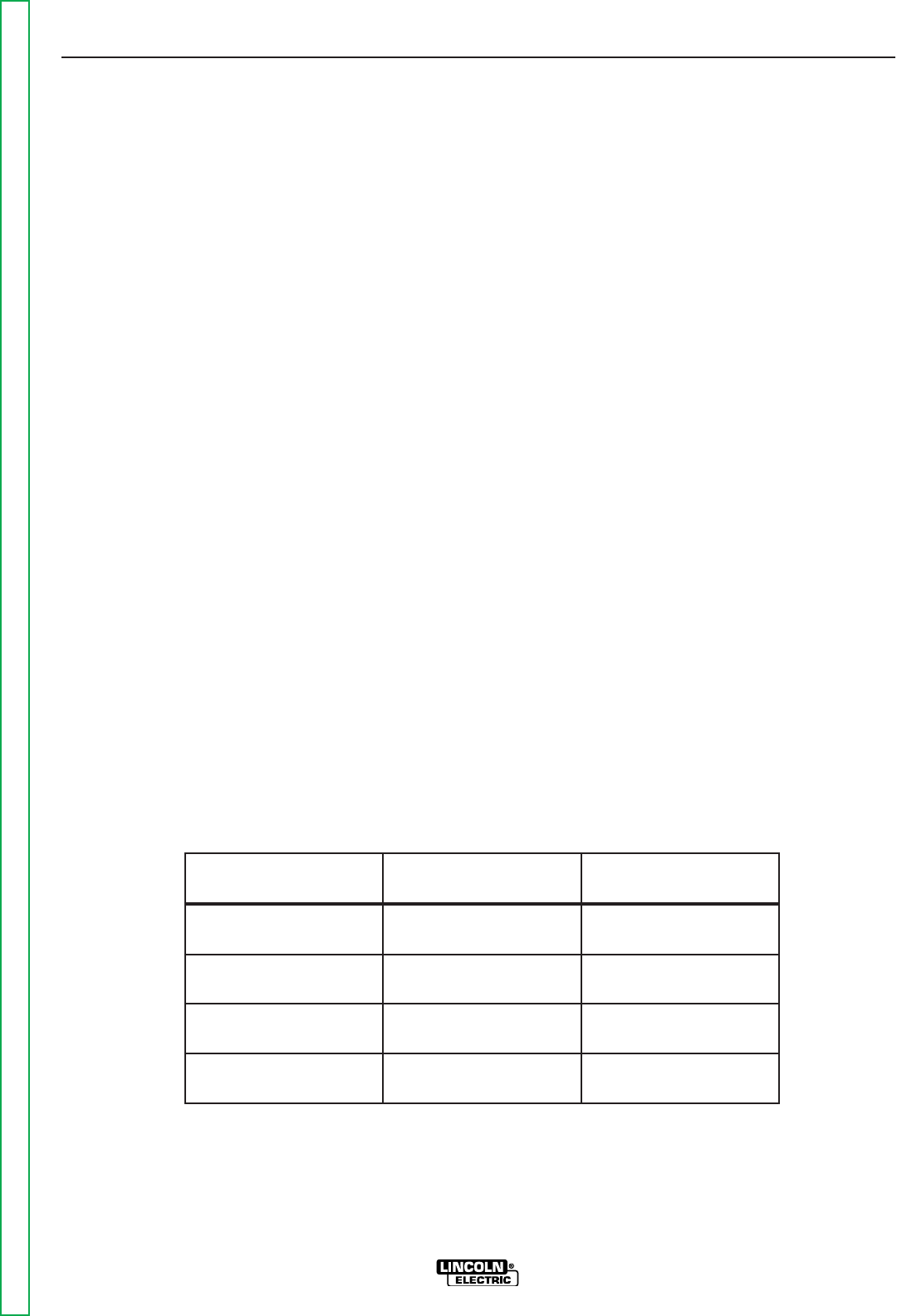
0%%,"3
-45?8Located below are copper cable sizes rec-
ommended for various currents and duty cycles.
Lengths stipulated are the distance from the welder to
work and back to the welder again. Cable sizes are
increased for greater lengths primarily for the purpose
of minimizing voltage drop in the cables.
** Tabled values are for operation at ambient temperatures of 104°F(40°C) and below. Applications above 104°F(40°C) may require cables
larger than recommended, or cables rated higher than 167°F(75°C).
+(&&'%,"3,+.+(/+())++-QBEQ
CABLE SIZES FOR COMBINED LENGTHS OF ELECTRODE AND WORK CABLES
AMPERES
200
200
225
225
250
250
250
250
300
325
350
400
400
500
PERCENT
DUTY
CYCLE
60
100
20
40 & 30
30
40
60
100
60
100
60
60
100
60
GBG
GB@
2
2
4 or 5
3
3
2
1
1
1
2/0
1/0
2/0
3/0
2/0
GBG
GB@
2
2
3
3
3
2
1
1
1
2/0
1/0
2/0
3/0
2/0
GBG
GB@
2
2
2
2
2
1
1
1
1
2/0
2/0
2/0
3/0
3/0
GBG
GB@
1
1
1
1
1
1
1
1
1/0
2/0
2/0
3/0
3/0
3/0
GBG
GB@
1/0
1/0
1/0
1/0
1/0
1/0
1/0
1/0
2/0
3/0
3/0
4/0
4/0
4/0
-%
,-2)+.-"(',
%-+"Z,!($'$"%%
R-HEAG;8<ACHGCBJ8E(4GG;8
7<F6BAA86GFJ<G6;BE9HF85BK
589BE84GG8@CG<A:GB6BAA86GBE
7<F6BAA86G<ACHGCBJ8E?<A8FBHG
CHG645?8FBE6BAGEB?645?8F
R(A?LDH4?<9<87C8EFBAA8?F;BH?7
C8E9BE@G;<F<AFG4??4G<BA
RBABGGBH6;@8G4?CBEG<BAFB9G;8%'S)+(
JBE>6?<CJ;8AG;8J8?7<A:CBJ8EFBHE68<FBA
RBABG4GG46;G;8JBE>6?<CGBG;8J<E898878E
RBAA86GG;8JBE>6?<C7<E86G?LGBG;8JBE>4F
6?BF84FCBFF<5?8GBG;8J8?7<A:4E6
R-HEACBJ8EB994GG;8J8?7<A:CBJ8EFBHE68
589BE87<F6BAA86G<A:G;8JBE>6?<C9EB@G;8
JBE>
R(A?LHF8BACBJ8EFBHE68FJ<G;BC8A6<E6H<G
IB?G4:8F?8FFG;4A/
%(-"('
For best wire feeding performance, place the LN-
25™ PRO on a stable and dry surface. Keep the
wire feeder in a vertical position. Do not operate the
wire feeder on an angled surface of more than 15
degrees.
Do not submerge the LN-25™ PRO.
The LN-25™ PRO is rated IP23 and is suitable for
outdoor use.
The handle of the LN-25™ PRO is intended for
moving the wire feeder about the work place only.
When suspending a wire feeder, insulate the
hanging device from the wire feeder enclosure.
!" !+*.'2)+(--"('
%B64G8G;8%'S)+(4J4L9EB@E47<B6BAGEB??87
@46;<A8EL -;8 ABE@4? BC8E4G<BA B9 G;8 %'S
)+(@4L47I8EF8?L49986GG;8BC8E4G<BAB9+6BA
GEB??878DH<C@8AGJ;<6;@4LE8FH?G<A5B7<?L<A=HEL
BE74@4:8GBG;88DH<C@8AG
0+'"'
.-"('
Return to Section TOC Return to Section TOC Return to Section TOC Return to Section TOC
Return to Master TOC Return to Master TOC Return to Master TOC Return to Master TOC
"',-%%-"('
%'S)+(
2. Remove the cylinder cap. Inspect the cylinder valves
and regulator for damaged threads, dirt, dust, oil or
grease. Remove dust and dirt with a clean cloth. (
'(- --! -! + .%-(+ " ("% +,
(+& ",)+,'-Inform your gas supplier
of this condition. Oil or grease in the presence of high
pressure oxygen is explosive
.
3. Stand to one side away from the outlet and open the
cylinder valve for an instant. This blows away any dust
or dirt which may have accumulated in the valve outlet.
4. Attach the flow regulator to the cylinder valve and tight-
en the union nut(s) securely with a wrench. Note: if
connecting to 100% CO2cylinder, insert regulator
adapter between regulator and cylinder valve. If
adapter is equipped with a plastic washer, be sure it is
seated for connection to the CO2cylinder.
5. Attach one end of the inlet hose to the outlet fitting of
the flow regulator. Attach the other end to the welding
system shielding gas inlet. Tighten the union nuts with
a wrench.
6. Before opening the cylinder valve, turn the regulator
adjusting knob counterclockwise until the adjusting
spring pressure is released.
7. Standing to one side, open the cylinder valve slowly a
fraction of a turn. When the cylinder pressure gage
stops moving, open the valve fully.
8. The flow regulator is adjustable. Adjust it to the flow
rate recommended for the procedure and process
being used before making a weld.
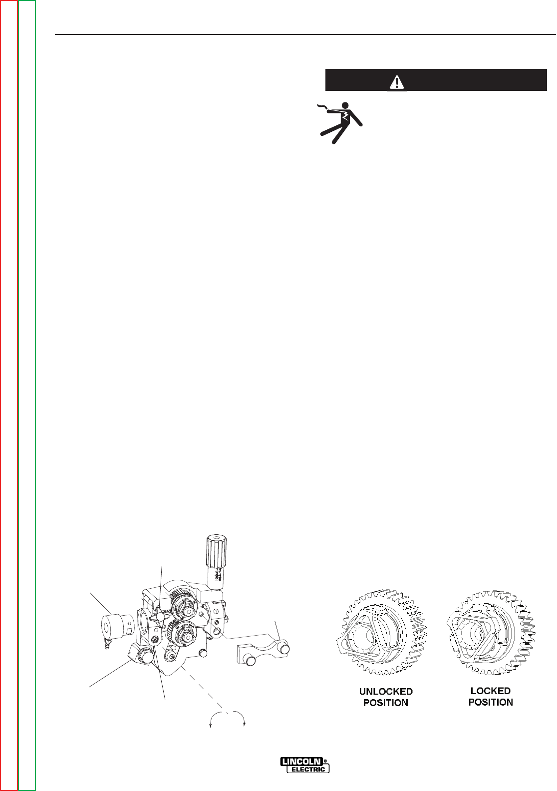
0"++"/('" .+-"('
(See Figure A.1)
!' "' -! .' +"/+
.,!"'
%-+",!($64A><??
R-HEAG;8<ACHGCBJ8E(4GG;8J8?7
<A:CBJ8E FBHE68 589BE8 <AFG4??4G<BA
BE6;4A:<A:7E<I8EB??F4A7BE:H<78F
RBABGGBH6;8?86GE<64??L?<I8C4EGF
R0;8A<A6;<A:J<G;G;8:HAGE<::8E8?86GEB784A7
7E<I8@86;4A<F@4E8;BGGBJBE>4A7:EBHA7
4A7 6BH?7 E8@4<A 8A8E:<M87 F8I8E4? F86BA7F
49G8EG;8:HAGE<::8E<FE8?84F87
RB ABG BC8E4G8 J<G; 6BI8EF C4A8?F BE :H4E7F
E8@BI87BEBC8A
R(A?LDH4?<9<87C8EFBAA8?F;BH?7C8E9BE@@4<AG8
A4A68JBE>
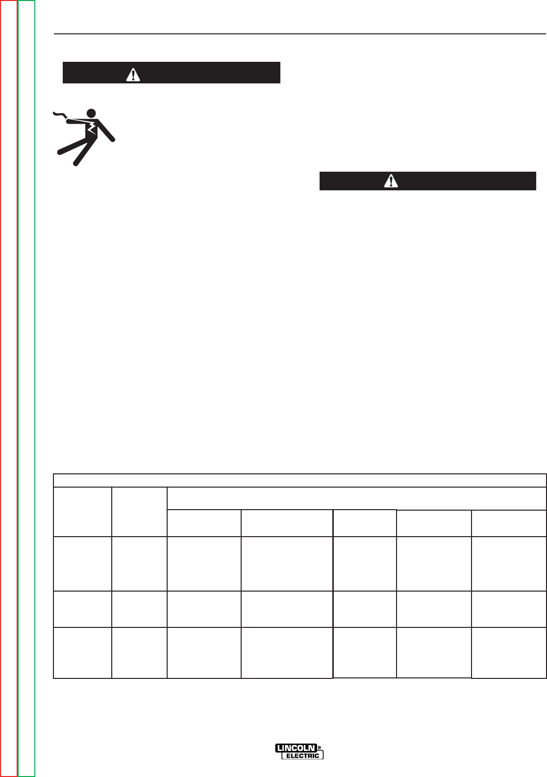
)<A
A
B
C
D
E
0<E<A:
Trigger
Not used
Common
Not used
Not used
%(''-"(',
There is one circular connector for the gun trigger on
the front of the LN-25™ PRO.
HA6G<BA
5-pin trigger
connector for
push-guns
only.
A
E
CB
D
-45?8
0+'"'
,!"%"' ,(''-"('
2%"'+ @4L 8KC?B78 <9
74@4:87
R $88C 6L?<A78E HCE<:;G 4A7
6;4<A87GBFHCCBEG
R$88C6L?<A78E4J4L9EB@4E84FJ;8E8<G@4L58
74@4:87
R'8I8E?<9GJ8?78EJ<G;6L?<A78E4GG46;87
R'8I8E4??BJJ8?7<A:8?86GEB78GBGBH6;6L?<A78E
R$88C6L?<A78E4J4L9EB@J8?7<A:BEBG;8E?<I8
8?86GE<64?6<E6H<GF
R."% .) ( ,!"%"' , &2
!+&!%-!(+$"%%
R,;HGB99F;<8?7<A::4FFHCC?LJ;8AABG<A
HF8
R,88 @8E<64A '4G<BA4? ,G4A74E7 3 ,498GL
<A 08?7<A: 4A7 HGG<A:X )H5?<F;87 5L G;8
@8E<64A08?7<A:,B6<8GL
Maximum inlet pressure is 100 psi. (6.9 bar.)
Install the shielding gas supply as follows:
1. Secure the cylinder to prevent it from falling.
0+'"'
Return to Section TOC Return to Section TOC Return to Section TOC Return to Section TOC
Return to Master TOC Return to Master TOC Return to Master TOC Return to Master TOC
"',-%%-"('
%'S)+(
Tools required:
• 1/4" hex key wrench.
1. Turn power off at the welding power source.
2. Remove the welding wire from the wire drive.
3. Remove the thumb screw from the wire drive.
4. Remove the welding gun from the wire drive.
5. Loosen the socket head cap screw that holds the
connector bar against the gun bushing.
"&)(+-'-
BABG4GG8@CGGB6B@C?8G8?LE8@BI8G;8FB6>8G
;84764CF6E8J
6. Remove the outer wire guide, and push the gun
bushing out of the wire drive. Because of the pre-
cision fit, light tapping may be required to remove
the gun bushing.
7. Disconnect the shielding gas hose from the gun
bushing, if required.
8. Connect the shielding gas hose to the new gun
bushing, if required.
9. Rotate the gun bushing until the thumb screw hole
aligns with the thumb screw hole in the feed plate.
Slide the gun receiver bushing into the wire drive
and verify the thumb screw holes are aligned.
10. Tighten the socket head cap screw.
11. Insert the welding gun into the gun bushing and
tighten the thumb screw.
'(-: Some gun bushings do not require the use of
the thumb screw.
GUN RECEIVER BUSHING
LOOSEN TIGHTEN
THUMB SCREW
OUTER WIRE GUIDE
SOCKET HEAD
CAP SCREW
CONNECTOR BLOCK
)+(.+ -( "',-%% +"/ +(%%,
'0"+ .",
R -HEAG;8<ACHGCBJ8E(4GG;8J8?7
<A: CBJ8E FBHE68 589BE8 <AFG4??4G<BA
BE6;4A:<A:7E<I8EB??F4A7BE:H<78F
RBABGGBH6;8?86GE<64??L?<I8C4EGF
R0;8A<A6;<A:J<G;G;8:HAGE<::8E8?86GEB784A7
7E<I8@86;4A<F@4E8;BGGBJBE>4A7:EBHA7
4A7 6BH?7 E8@4<A 8A8E:<M87 F8I8E4? F86BA7F
49G8EG;8:HAGE<::8E<FE8?84F87
RB ABG BC8E4G8 J<G; 6BI8EF C4A8?F BE :H4E7F
E8@BI87BEBC8A
R(A?LDH4?<9<87C8EFBAA8?F;BH?7C8E9BE@@4<AG8
A4A68JBE>
------------------------------------------------------------------------
1. Turn power off at the welding power source.
2. Release the idle roll pressure arm.
3. Remove the outer wire guide by turning the knurled
thumbscrews counter-clockwise to unscrew them
from the feed plate. See <:HE8.
4. Rotate the triangular lock and remove the drive rolls.
5. Remove the inner wire guide
6. Insert the new inner wire guide, groove side out,
over the two locating pins in the feed plate.
7. Install a drive roll on each hub assembly secure with
the triangular lock.
8. Install the outer wire guide by aligning it with the pins
and tightening the knurled thumbscrews.
9. Close the idle arm and engage the idle roll pressure
arm. Adjust the pressure appropriately.
0+'"'
" .+
" .+
Return to Section TOC Return to Section TOC Return to Section TOC Return to Section TOC
Return to Master TOC Return to Master TOC Return to Master TOC Return to Master TOC
"',-%%-"('
%'S)+(
THUMB
SCREW
GUN
)+,,.++&#.,-&'-
%-+",!($64A><??
R-HEAG;8<ACHGCBJ8E(4GG;8J8?7
<A:CBJ8EFBHE68589BE8<AFG4??4G<BABE
6;4A:<A:7E<I8EB??F4A7BE:H<78F
RBABGGBH6;8?86GE<64??L?<I8C4EGF
R0;8A<A6;<A:J<G;G;8:HAGE<::8E8?86GEB784A7
7E<I8@86;4A<F@4E8;BGGBJBE>4A7:EBHA7
4A7 6BH?7 E8@4<A 8A8E:<M87 F8I8E4? F86BA7F
49G8EG;8:HAGE<::8E<FE8?84F87
RB ABG BC8E4G8 J<G; 6BI8EF C4A8?F BE :H4E7F
E8@BI87BEBC8A
R(A?LDH4?<9<87C8EFBAA8?F;BH?7C8E9BE@@4<AG8
A4A68JBE>
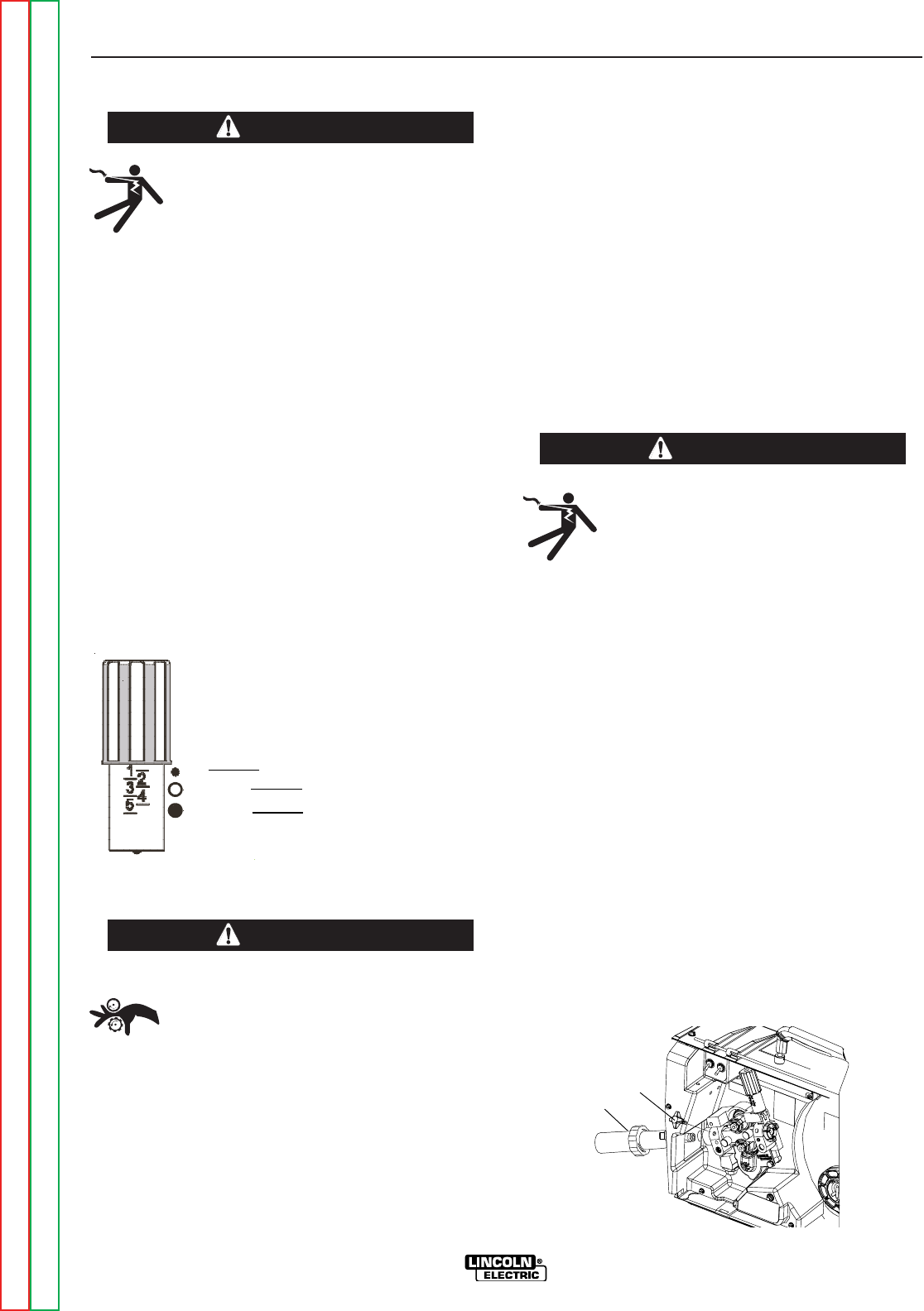
The pressure arm controls the amount of force the
drive rolls exert on the wire. Proper adjustment of the
pressure arm gives the best welding performance.
Set the pressure arm as follows:
(See <:HE8)
Aluminum wires between 1 and 3
Cored wires between 3 and 4
Steel, Stainless wires between 4 and 6
%("' ,)((%,(0"+
R$88C;4A7F;4<E6?BG;<A:4A7GBB?F
4J4L9EB@EBG4G<A:8DH<C@8AG
RBABGJ84E:?BI8FJ;8AG;E847<A:
J<E8BE6;4A:<A:J<E8FCBB?
R(A?LDH4?<9<87C8EFBAA8?F;BH?7<AFG4??
HF8BEF8EI<68G;<F8DH<C@8AG
Loading 10 to 15 lb. (4.5 – 6.8kg) Spools.
A K468 spindle adapter is required for loading 2"
(51mm) wide spools on 2" (51mm) spindles. Use a
K468 spindle adapter for loading 2-1/2" (64mm) wide
spools.
1. Squeeze the release bar on the retaining collar and
remove it from the spindle.
2. Place the spindle adapter on the spindle, aligning
the spindle brake pin with the hole in the adapter.
3. Place the spool on the spindle and align the adapter
brake tab with one of the holes in the back side of
the spool. An indicator mark on the end of the spin-
dle shows the orientation of the brake tab. Be cer-
tain the wire feeds off of the spool in the proper
direction.
4. Re-install the retaining collar. Make sure that the
release bar snaps out and that the retaining collar
fully engages the groove on the spindle.
.'(''-"('
%-+",!($64A><??
R-HEAG;8<ACHGCBJ8E(4GG;8J8?7
<A:CBJ8EFBHE68589BE8<AFG4??4G<BABE
6;4A:<A:7E<I8EB??F4A7BE:H<78F
RBABGGBH6;8?86GE<64??L?<I8C4EGF
R0;8A<A6;<A:J<G;G;8:HAGE<::8E8?86GEB784A7
7E<I8@86;4A<F@4E8;BGGBJBE>4A7:EBHA7
4A7 6BH?7 E8@4<A 8A8E:<M87 F8I8E4? F86BA7F
49G8EG;8:HAGE<::8E<FE8?84F87
RB ABG BC8E4G8 J<G; 6BI8EF C4A8?F BE :H4E7F
E8@BI87BEBC8A
R(A?LDH4?<9<87C8EFBAA8?F;BH?7C8E9BE@@4<AG8
A4A68JBE>
The LN-25™ PRO comes with a K1500-2 gun adapter
installed. (See <:HE8)
To install a gun,
1. Turn power OFF.
2. Remove the thumb screw.
3. Push the gun the completely into the gun bushing.
4. Secure the gun in place with the thumb screw.
5. Connect the trigger cable from the gun to the trigger
connector on the front of the feeder.
Note: Not all gun bushings require the use of the
thumb screw.
0+'"'
0+'"'
6
Al
Fe, CrNi
Fe, CrNi
ALUMINUM WIRES
CORED WIRES
STEEL, STAINLESS WIRES
" .+
0+'"'
" .+
Return to Section TOC Return to Section TOC Return to Section TOC Return to Section TOC
Return to Master TOC Return to Master TOC Return to Master TOC Return to Master TOC
"',-%%-"('
%'S)+(
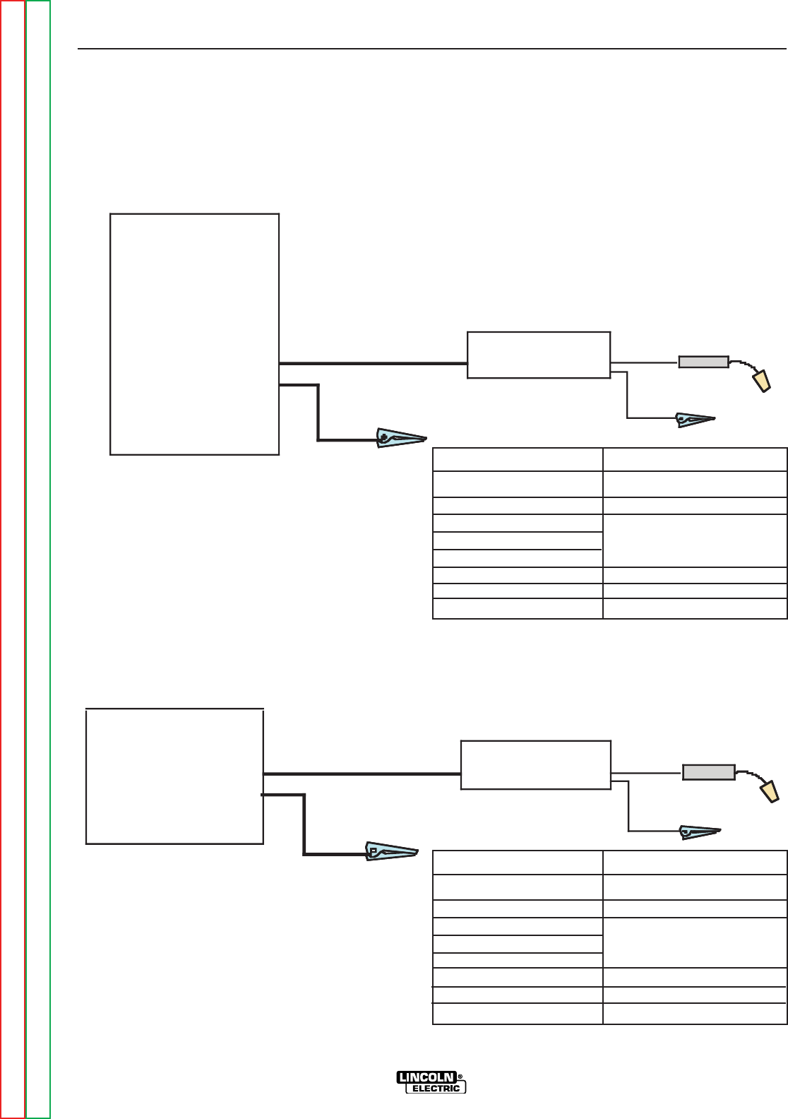
+(,,-!+,-.),
)BJ8E,BHE68FJ<G;(HGCHG-8E@<A4?F?J4LF
!BG,88<:HE8
If the power source has a Remote/Local switch, place
the switch in the Local position.
Place the Power Source CC/CV switch (if present) or
Range Switch in the CV position if possible.
Set the CV/CC switch in the feeder to match the power
source.
/ )BJ8E ,BHE68F J<G; ,GH7 BAA86GBEF 4A7
+8@BG8%B64?,J<G6;,88<:HE8
Place the power source Remote/Local switch in the
Local position.
Place CV/CC switch in the feeder in the "CV" position.
LN-25 PRO
(Across the Arc)
CC Power Source
Ranger 250, 250 LPG
Ranger 305G, 305D
Commander 300
Vantage 300, 400, 500
Air Vantage 500
Ranger 10,000
Ranger 3 phase
SAE 400 with CV adapter
Engine Driven welder with
Wire Feed Module Work
Electrode
Work clip
LN-25 PRO
(Across the Arc)
Work
Electrode
Work clip
CV-655
CV-400
DC-400
DC-600
DC-655
V450-Pro
" .+
" .+
$
K2613-1
K2613-2
KP1695-XX
KP1696-XX
KP1697-XX
See Magnum Literature
K1803-1
8F6E<CG<BA
LN-25™ PRO Wire Feeder
LN-25™ PRO Extra Torque
Drive Roll Kit
Welding Gun
CC power Source
Welding Cables
)(0+,(.+-(%'S)+(
%(''-"('" +&,
$
K2613-1
K2613-2
KP1695-XX
KP1696-XX
KP1697-XX
See magnum Literature
K1803-1
8F6E<CG<BA
LN-25™ PRO Wire Feeder
LN-25™ PRO Extra Torque
Drive Roll Kit
Welding Gun
CV power Source
Welding Cables
Return to Section TOC Return to Section TOC Return to Section TOC Return to Section TOC
Return to Master TOC Return to Master TOC Return to Master TOC Return to Master TOC
"',-%%-"('
%'S)+(
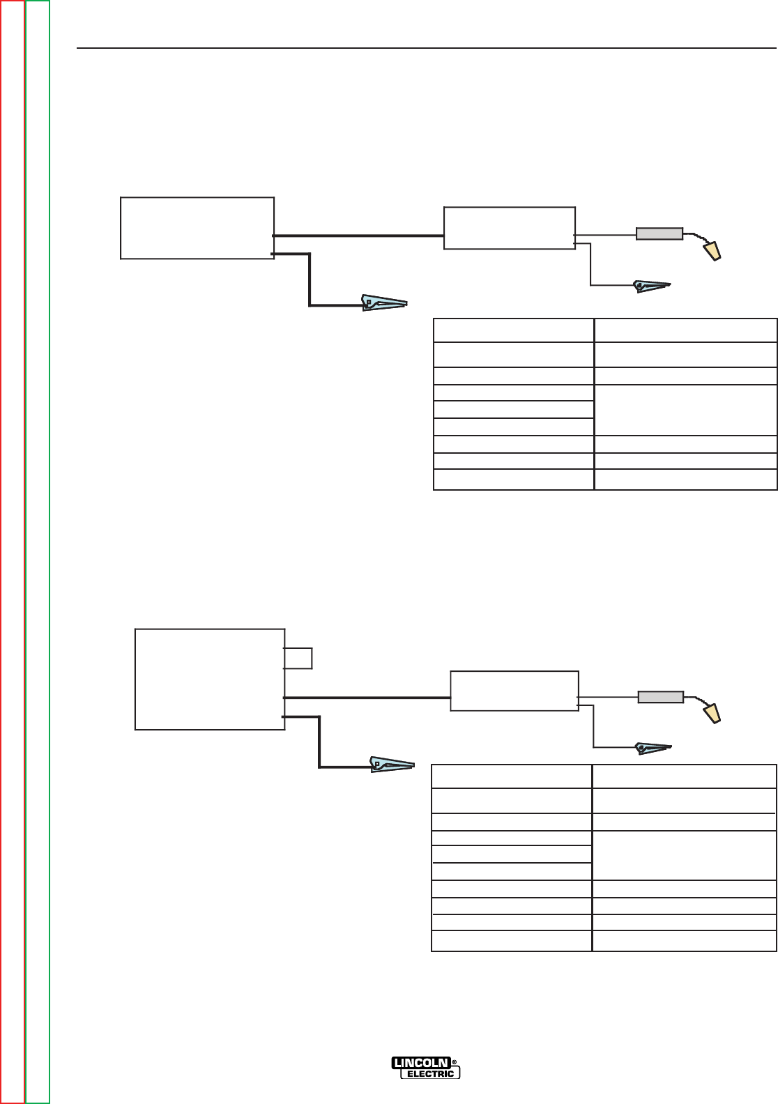
/)BJ8E,BHE68J<G;-J<FG&4G8BAA86GBEF4A7
+8@BG8%B64?,J<G6;,88<:HE8
Place CV/CC switch in the feeder in the "CV" position.
LN-25 PRO
(Across the Arc)
V350-Pro
Work
Electrode
Work clip
" .+
$
K2613-1
K2613-2
KP1695-XX
KP1696-XX
KP1697-XX
See Magnum Literature
K1841
8F6E<CG<BA
LN-25™ PRO Wire Feeder
LN-25™ PRO Extra Torque
Drive Roll Kit
Welding Gun
CC power Source
Welding Cables
/)BJ8E,BHE68J<G;-J<FG&4G8BAA86GBEF4A7
AB+8@BG8%B64?,J<G6;,88<:HE8
Place CV/CC switch in the feeder in the "CV" position.
LN-25 PRO
(Across the Arc)
CV-250
CV-300
CV-305
Work
Electrode
Jumper
Work clip
" .+
$
K2613-1
K2613-2
KP1695-XX
KP1696-XX
KP1697-XX
See Magnum Literature
K1841-
K484
8F6E<CG<BA
LN-25™ PRO Wire Feeder
LN-25™ PRO Extra Torque
Drive Roll Kit
Welding Gun
CV power Source
Welding Cables
Jumper Plug kit
Return to Section TOC Return to Section TOC Return to Section TOC Return to Section TOC
Return to Master TOC Return to Master TOC Return to Master TOC Return to Master TOC

-%(('-'-,()+-"(',-"('
%'S)+(
(C8E4G<BA
Safety Precautions and Graphic Symbol Definitions . . . . . . . . . . . . . . . . . . . . . . . . . . . . . . . . . . . . . . . . . .B-2
General Description . . . . . . . . . . . . . . . . . . . . . . . . . . . . . . . . . . . . . . . . . . . . . . . . . . . . . . . . . . . . . . . . . . .B-3
Case Front Controls . . . . . . . . . . . . . . . . . . . . . . . . . . . . . . . . . . . . . . . . . . . . . . . . . . . . . . . . . . . . . .B-4 / B-8
CV Wire Feed Speed Operation . . . . . . . . . . . . . . . . . . . . . . . . . . . . . . . . . . . . . . . . . . . . . . . . . . . . . .B-4
CC Wire Feed Speed Operation . . . . . . . . . . . . . . . . . . . . . . . . . . . . . . . . . . . . . . . . . . . . . . . . . . . . .B-5
CV Wire Feed Speed Operation . . . . . . . . . . . . . . . . . . . . . . . . . . . . . . . . . . . . . . . . . . . . . . . . . . . . . .B-5
Constant Current vs Constant Voltage Wire Welding . . . . . . . . . . . . . . . . . . . . . . . . . . . . . . . . . . . . . .B-7
Internal Controls . . . . . . . . . . . . . . . . . . . . . . . . . . . . . . . . . . . . . . . . . . . . . . . . . . . . . . . . . . . . . . . . . . . . . .B-9
Description of Internal Controls . . . . . . . . . . . . . . . . . . . . . . . . . . . . . . . . . . . . . . . . . . . . . . . . . . . .B-10 / B-11
Rear Controls . . . . . . . . . . . . . . . . . . . . . . . . . . . . . . . . . . . . . . . . . . . . . . . . . . . . . . . . . . . . . . . . . . . . . . .B-12
Gas Purge/Flow Meter/Power-Up . . . . . . . . . . . . . . . . . . . . . . . . . . . . . . . . . . . . . . . . . . . . . . . . . . . . . . .B-13
Return to Master TOC Return to Master TOC Return to Master TOC Return to Master TOC
()+-"('
%'S)+(
R%-+" ,!($ ' $"%%
.A?8FF HF<A: (% 984
GHE8J;8A9887<A:J<G;:HAGE<:
:8E G;8 8?86GEB78 4A7 7E<I8
@86;4A<F@ 4E8 4?J4LF 8?86GE<
64??L 8A8E:<M87 4A7 6BH?7
E8@4<A 8A8E:<M87 F8I8E4? F86
BA7F49G8EG;8J8?7<A:684F8F
RB ABG GBH6; 8?86GE<64??L ?<I8 C4EG BE 8?86GEB78
J<G;F><ABEJ8G6?BG;<A:
R"AFH?4G8LBHEF8?99EB@JBE>4A7:EBHA7
R?J4LFJ84E7EL<AFH?4G<A::?BI8F
RB ABG BC8E4G8 J<G; 6BI8EF C4A8?F BE :H4E7F
E8@BI87BEBC8A
R.&, ' ,,, 64A 58
74A:8EBHF
R$88CLBHE;847BHGB99H@8F
R.F8 I8AG<?4G<BA BE 8K;4HFG GB
E8@BI8 9H@8F 9EB@ 5E84G;<A:
MBA8
R0%"' ,)+$, 64A 64HF8
9<E8BE8KC?BF<BA
R$88C9?4@@45?8@4G8E<4?4J4L
+Z+2,64A5HEA
R084E 8L8 84E 4A7 5B7L CEBG86
G<BA
, "-"('% 0+'"' "'(+&-"('
.'++ 0%"' ,-2)+.-"(',
'"'-! +('-(-!",()+-"' &'.
%
0+'"'
,-2)+.-"(',
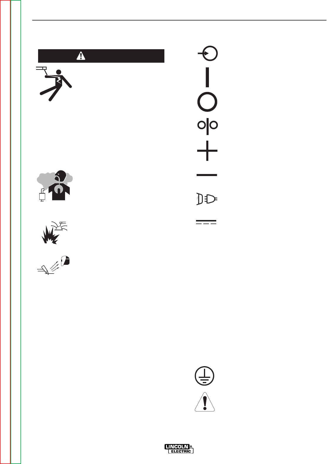
+ ' .'+,-' '-"+ ,-"('
(+()+-"' &!"'
"').-)(0+
('
(
0"++
)(,"-"/(.-).-
' -"/(.-).-
"').-)(0+
"+-.++'-
()'"+."-
/(%-
"').-/(%-
(.-).-/(%-
"').-.++'-
(.-).-.++'-
)+(--"/
+(.'
0+'"' (+
.-"('
.
.
.
"
"
+)!" ,2&(%, -!- ))+ ('
-!",&!"'(+"'-!",&'.%
Return to Section TOC Return to Section TOC Return to Section TOC Return to Section TOC
Return to Master TOC Return to Master TOC Return to Master TOC Return to Master TOC

()+-"('
%'S)+(
"'"-"('(0%"' -+&,
0,
• Wire Feed Speed
RConstant Current
/
RConstant Voltage
&0
• Gas Metal Arc welding
,&0
RShielded Metal Arc welding
0
RFlux Core Arc Welding
'+%,+")-"('
8A8E4?);LF<64?8F6E<CG<BA
The LN-25™ PRO is specially engineered to be the
most rugged portable wire feeder available. The mod-
els covered by this manual are designed for “across
the arc” operation only.
Several models of the LN-25™ PRO are offered to
best meet individual welder needs. The Extra Torque
model features additional torque gearing for reliable
feeding of large diameter FCAW wires. The Standard
model features wire drive gearing for optimal perfor-
mance for both FCAW and GMAW wires of common
sizes. All of the models include a gas solenoid and
flow meter for the flexibility to run most wire processes.
The plastic case is molded from a high impact, flame
retardant plastic for durability and low weight. The
patent pending design keeps the internal components
protected and dry.
The heart of the LN-25™ PRO is the 2 roll MAX-
TRAC™ drive. The patented features on the wire drive
offer tool-less changing of the drive rolls and wire
guides for quick spool changes. A tachometer con-
trolled motor powers the patent pending drive rolls for
smooth, steady feeding without slippage.
With only one p.c. board, the LN-25™ PRO is
designed to be simple, reliable and easy to service.
The p.c. board is mounted with Lincoln’s leading envi-
ronmental design protection that consists of mounting
the board in a plastic tray and potting it with epoxy.
With a 325 amp 100% duty cycle rating, these feeders
are ready for heavy duty welding.
8A8E4?HA6G<BA4?8F6E<CG<BA
The LN-25™ PRO as designed is a simple, robust
feeder. Standard features include a calibrated wire
feed speed dial, 2 step/trigger interlock switch, CV-CC
switch, Gas Purge and Cold Feed. Some newer codes
also have a Wire Speed range switch for more precise
setting at lower speeds.
+(&&')+(,,,
• GMAW
• FCAW
)+(,,%"&"--"(',
• GMAW-P procedures must be qualified by the cus-
tomer.
• Across-the-Arc models are not recommended for
stitch or spot welding.
*.")&'-%"&"--"(',
• The duty cycle of the wire feeder is 325A, 100% and
450A, 60%. Duty cycle is based upon the amount of
welding performed in a 10 minute period.
• The maximum spool size is 45 lb, 12" diameter.
• Maximum FCAW gun length is 15 ft.
• Maximum GMAW gun length is 25 ft.
• Push-pull guns do not work with the wire feeder.
• K2330-1 Timer kits do not work with this feeder, use
K2330-2 kits
+(&&')(0+,(.+,
• CV-305
• CV-400
• CV-655
• DC-400
• DC-600
• DC-655
• Invertec V-350 PRO
• Invertec V-450 PRO
• Multi-Weld 350
• Ranger 10,000
• Ranger 3 Phase
• Ranger GXT
• Ranger 250
• Ranger 305
• SAE-400
• Pipeliner 200G
• Classic 300
• Vantage 300
• Vantage 400
• Vantage 500
Return to Section TOC Return to Section TOC Return to Section TOC Return to Section TOC
Return to Master TOC Return to Master TOC Return to Master TOC Return to Master TOC
()+-"('
%'S)+(
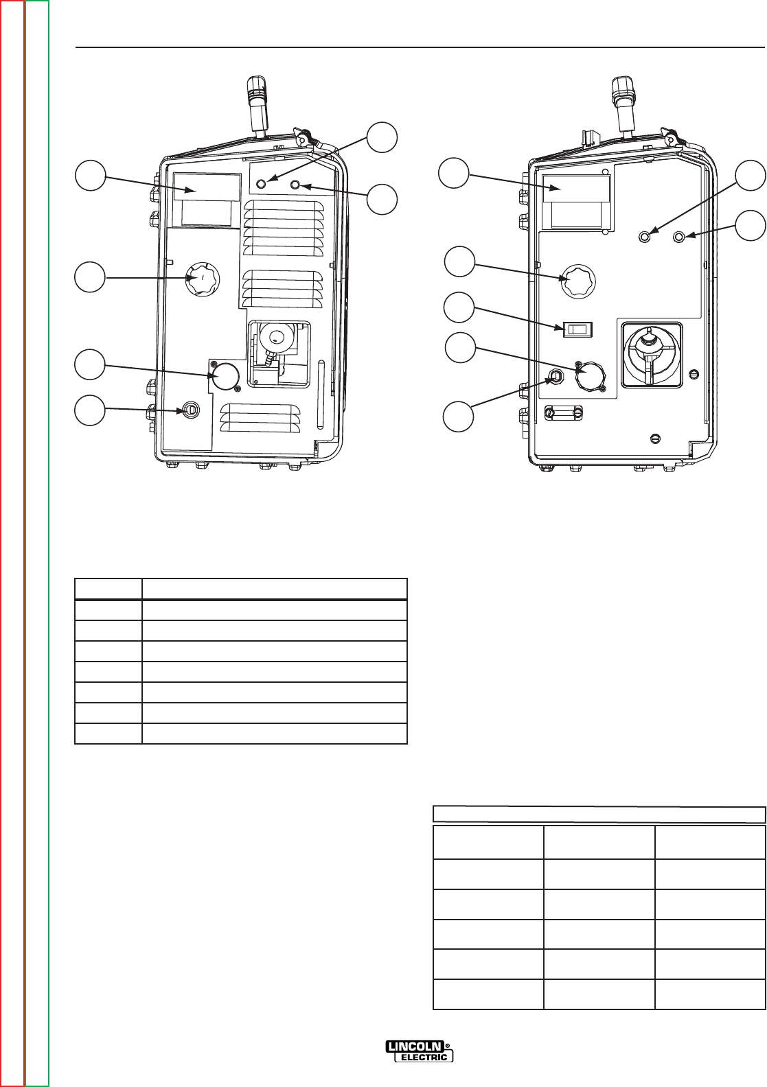
,+('-('-+(%, ,88<:HE8
'%( /(%-&-+
The analog voltmeter shows the voltage between
electrode and work. The voltmeter shows open cir-
cuit voltage when the wire feeder is not welding. As
a result, it is not unusual to see the needle “pegged”
when not welding. The voltmeter is polarity insensi-
tive and the range is 0 - 40VDC.
0"+,)$'(
The large, calibrated wire feed speed knob makes
for easy and accurate adjustment of the wire feed
speed. The knob rotates 3/4 turn. Turn the knob
clockwise to increase the wire feed speed, and
counter clockwise to reduce the wire feed speed.
Models with analog voltmeters have a calibrated
scale printed around the wire feed speed knob using
"in/min" units. A separate decal with "m/min" units is
included with these models wire feeder. Units with a
range switch have two calibrated scales.
0<E8887,C887/(C8E4G<BA
When Across the Arc models are operated with CV
power sources, the wire feed speed will remain a con-
stant value, independent of arc voltage changes, as
long as the arc voltage does not drop below the mini-
mum values per the following table.
-%/()+-"('
11
2
3
2
3
44
5
5
6
6
7
K2613-1 & K2613-2 K2613-5 & K2613-7
" .+
"-& ,+")-"('
1. Analog Voltmeter
2. Wire Feed Speed Control
3. 5-Pin Gun Trigger Receptacle
4. Work Sense Lead Connector
5 Thermal LED (Motor Overload)
6. Polarity LED
7. Wire Feed Speed Range Switch
&<A<@H@
E6/B?G4:8
&4K<@H@0,
,G4A74E7
&4K<@H@0,
KGE4-BEDH8
15 V 280”/min. 210”/min.
17V 340”/min. 235”/min.
21V 440”/min. 400”/min.
24V 520”/min. 400”/min.
27V 600”/min 400”/min.
Return to Section TOC Return to Section TOC Return to Section TOC Return to Section TOC
Return to Master TOC Return to Master TOC Return to Master TOC Return to Master TOC
()+-"('
%'S)+(
50
100
150
200
250
300
350
400
450
500
550
600
650
700
50 100 150 200 250 300 350 400 450 500 550 650 700
35
31
29
27
25
23
21
19
17
15
33
600
V
CC
" .+
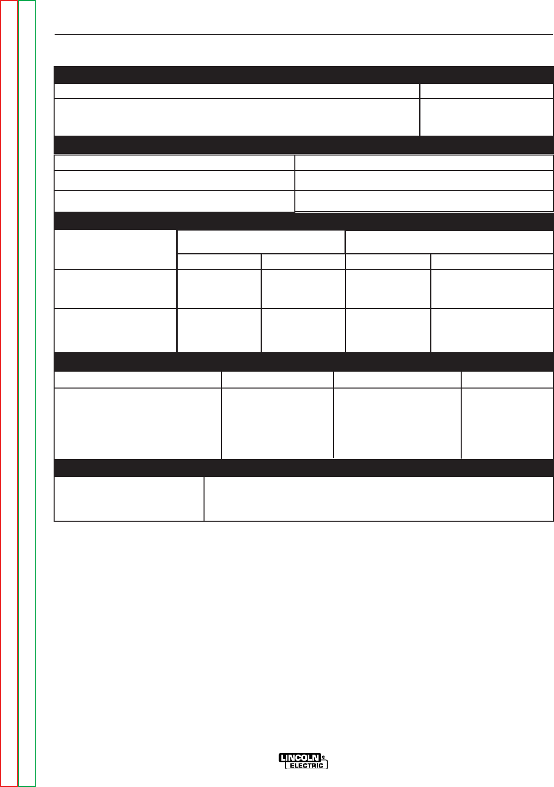
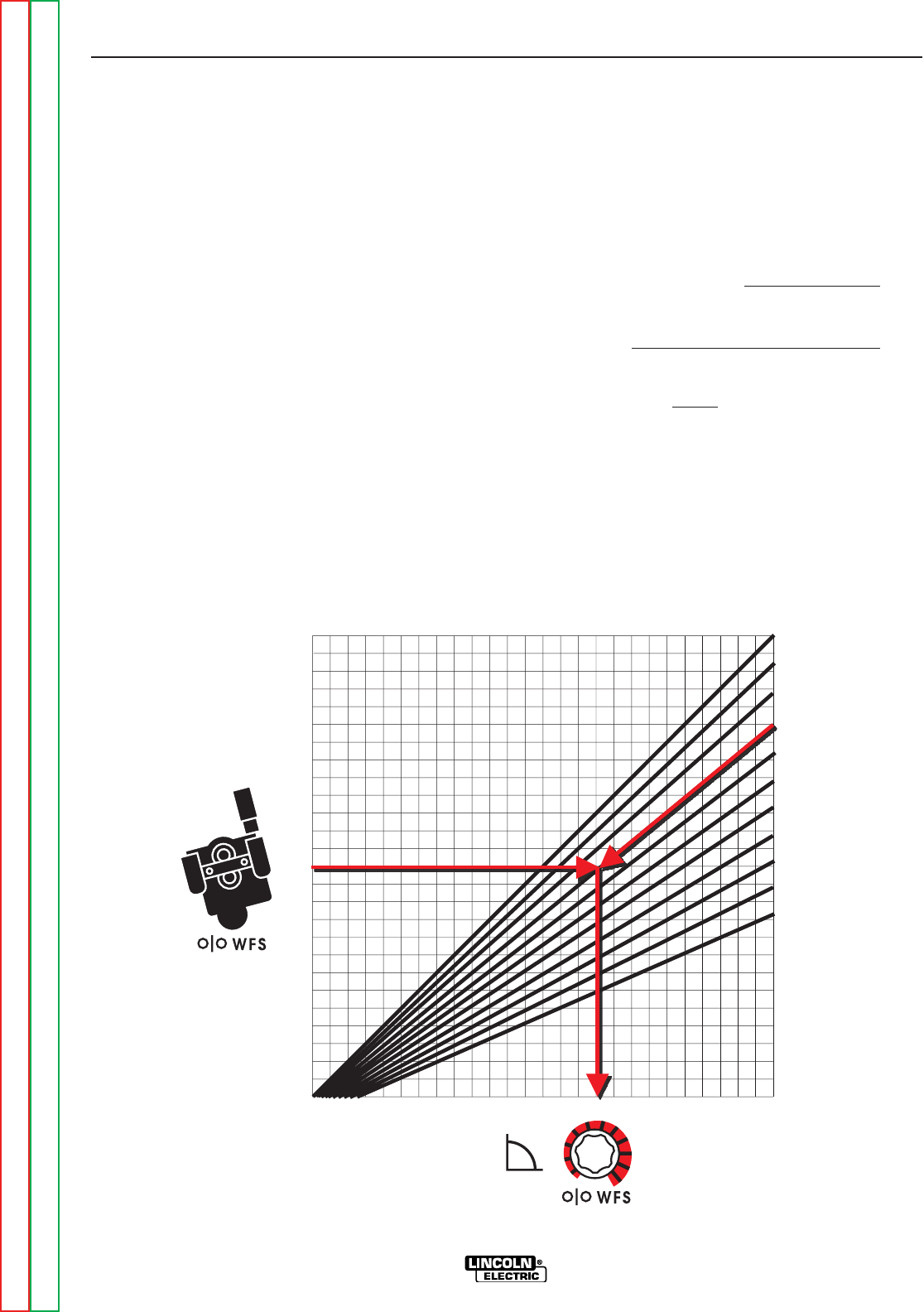
0<E8887,C887(C8E4G<BA(,88<:HE8BE
See Table B.2
When Across the Arc models are operated with CC
power sources, the wire feed speed changes as the arc
voltage changes. When the arc voltage increases, the
wire feed speed will increase; and when the arc voltage
decreases, the wire feed speed will decrease.
To preset the wire feed speed on CC power sources:
1. Set the Wire Feed Mode switch inside the LN-25™
PRO to "CC".
2. Refer to the Figure B.2 graph for the setting for the
wire feed speed knob setting. Select the horizon-
tal line representing the Desired Wire Feed Speed.
(See Figure B.2 arrow for 375 in/min.)
3. Select the diagonal line representing the Arc Volts.
(See Figure B.2 for 29 volts.)
4. Determine the vertical line representing the CC
representing the CC Wire Feed Speed setting
where the above two lines cross. (See Figure B.2
arrow line for 450.) Set the LN-25™ PRO wire feed
speed knob to this value.
CC WFS dial setting = desired WFS x 35
Arc Volts
Example: 375 in/min. (Horizontal Line) x 35
29 Arc Volts (Diagonal Line)
= 13125 = 452-5 (Vertical Line)
29
Set the Wire Speed Control at 450”/min.,
and when welding at 29 volts the average
actual speed should be approximately
375“/min.
Return to Section TOC Return to Section TOC Return to Section TOC Return to Section TOC
Return to Master TOC Return to Master TOC Return to Master TOC Return to Master TOC

()+-"('
%'S)+(
-%//0"+,),--"'
109
131
153
175
197
97
117
136
156
175
88
105
123
140
158
80
95
111
127
143
73
88
102
117
131
67
81
94
108
121
63
75
88
100
113
58
70
82
93
105
55
66
77
88
98
51
62
72
82
93
219
241
263
284
306
194
214
233
253
272
175
193
210
228
245
159
175
191
207
223
146
160
175
190
204
135
148
162
175
188
125
138
150
163
175
117
128
140
152
163
109
120
131
142
153
103
113
124
134
144
328
350
372
394
416
292
311
331
350
369
263
280
298
315
333
239
255
270
286
302
219
233
248
263
277
202
215
229
242
256
188
200
213
225
238
175
187
198
210
222
164
175
186
197
208
154
165
175
185
196
438
459
481
503
525
389
408
428
447
457
350
368
385
403
420
318
334
350
366
382
292
306
321
335
350
269
283
296
310
323
250
263
275
288
300
233
245
257
268
280
219
230
241
252
263
206
216
226
237
247
547
569
591
613
634
486
506
525
544
564
438
455
473
490
508
398
414
430
445
461
365
379
394
408
423
337
350
365
377
390
313
325
338
350
363
292
303
315
327
338
273
284
295
306
317
257
268
278
288
299
656
678
700
583
603
622
642
661
525
543
560
578
595
477
493
509
525
541
438
452
467
481
496
404
417
431
444
458
375
388
400
413
425
350
362
373
385
397
328
339
350
361
372
309
319
329
340
350
681
700
613
630
666
700
557
572
604
636
668
510
526
554
584
612
471
484
512
538
566
438
450
472
500
526
408
420
444
466
490
383
394
416
438
460
360
370
392
412
432
700 642
670
700
592
620
646
674
550
576
600
626
514
536
560
584
482
504
526
546
452
472
494
514
700 650
676
700
606
630
654
676
700
568
590
612
634
656
536
556
576
598
618
678
700
638
658
680
700
50
60
70
80
90
100
110
120
130
140
150
160
170
180
190
200
210
220
230
240
250
260
270
280
290
300
310
320
330
340
350
360
380
400
420
440
460
480
500
520
540
560
580
600
620
640
660
680
700
16 18 20 22 24 26 28 30 32 34
Arc Volts UsedDesired
In/Min
Return to Section TOC Return to Section TOC Return to Section TOC Return to Section TOC
Return to Master TOC Return to Master TOC Return to Master TOC Return to Master TOC
Return to Section TOC Return to Section TOC Return to Section TOC Return to Section TOC
Return to Master TOC Return to Master TOC Return to Master TOC Return to Master TOC
()+-"('
%'S)+(
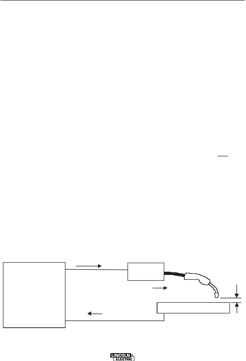
(',-'-.++'-/, (',-'-
/(%- 0"+0%"'
Most semiautomatic welding processes perform better
using constant voltage power sources.
Welding codes usually do not address the power
source selection or specifically, whether the welding
process is to be operated in the constant voltage or
constant current mode. Instead, codes typically spec-
ify limitations on the current, voltage, heat input and
preheat temperature based on the material to be weld-
ed. The intention is to assure that proper weld materi-
al properties will develop.
Welding is sometimes performed using constant cur-
rent power sources. The operation can be more con-
venient because it may allow the use of an existing
stick (SMAW) power source and the power source can
be placed at a distant location without any provision for
adjusting the output settings.
For constant current operation, the power source is set
to deliver the specified current. The power source reg-
ulates this current regardless of changes in the weld-
ing circuit, including cable length, electrode diameter,
wire feed speed, contact tip to work distance, etc.
Changes in the wire feed speed (WFS) or contact tip to
work distance (CTWD) affect the arc voltage when
constant current power sources are used. Lowering
the wire feed speed raises the voltage, raising the wire
feed speed lowers the voltage. Lengthening the con-
tact tip to work distance raises the voltage, shortening
the contact tip to work distance lowers the voltage.
(See <:HE8)
If the contact tip to work distance is properly main-
tained, a satisfactory operating voltage range may be
achieved, and a sound weld may result. However,
when a welder uses a longer contact tip to work dis-
tance, an arc-sensing wire feeder compensates by
increasing the wire feed speed to regulate the voltage.
Even if the voltage and current remain unchanged, the
increased wire feed speed may result in a deposition
rate well beyond the specified range of the electrode.
Under these conditions, the specified weld metal prop-
erties may not be achieved.
Constant voltage power sources deliver large current
surges to stabilize the arc when the electrode is short-
ed or the arc length is very short. However, a constant
current power source does not provide such a
response to stabilize the arc. It may be difficult to
achieve required weld metal properties, or to achieve
the required quality of welds needed to pass nonde-
structive tests, when such welds are made under con-
stant current operation.
For these reasons, Lincoln Electric does '(- recom-
mend constant current semiautomatic welding for
applications which need to meet specified weld metal
chemical or mechanical property requirements or weld
quality requirements.
Constant Current
Power Source
Wire
Feeder
Current
Current
CTWD
WFS
+
-
" .+
()+-"('
%'S)+(
)"' .'-+" +(''-(+
(See Figure B.1)
0(+$,',%
(See Figure B.1)
Must be connected for the drive motor to operate.
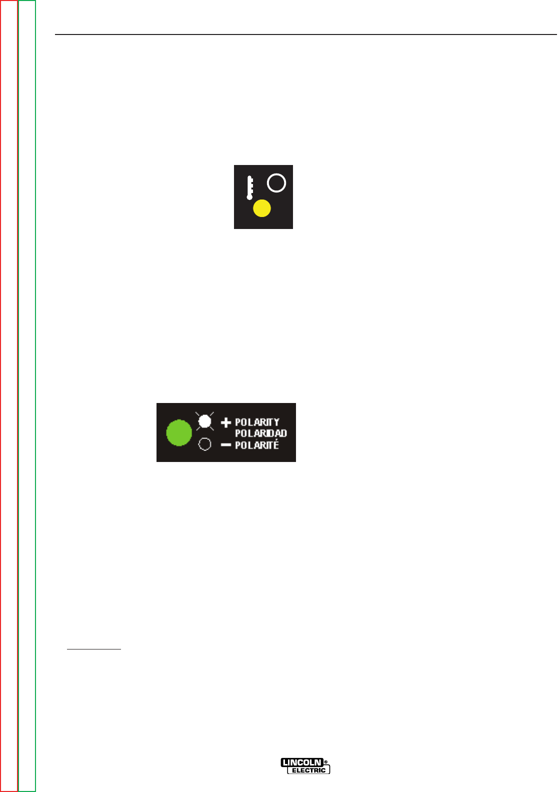
-!+&%%&(-(+(/+%(
(See Figure B.1)
The thermal light illuminates (yellow)
when the wire drive motor draws too
much current. If the thermal light illumi-
nates, the wire drive will automatically
shutdown for up to 30 seconds to allow
the motor to cool. To start welding
again, release the gun trigger, inspect the gun cable,
liner (and conduit). Clean and make repairs as nec-
essary. Start welding again when the problem has
been safely resolved.
For best results, keep the gun cable and conduit as
straight as possible. Perform regular maintenance
and cleaning on the gun liner, conduit and gun.
Always use quality electrode, such as L-50 or L-56
from Lincoln Electric.
)(%+"-2%
(See Figure B.1)
The Polarity LED
lights (green) when
the wire feeder is
connected for posi-
tive polarity. and is
not lit in Negative
Polarity. Use the polarity LED to verify the wire
feeder is connected properly for the process being
used.
'(- Both LED’s will flash briefly when power is
applied to the feeder.
7. 0"+ ,) +' ,0"-! $
4A7$BA?L
Used to select either HIGH or LOW range for the
Wire Feed Speed Control. LOW range allows for
more precise setting at lower feed rates. On the
Standard Torque models, selecting the LOW range
(, '(- increase the torque of the wire drive
system.
MM
Return to Section TOC Return to Section TOC Return to Section TOC Return to Section TOC
Return to Master TOC Return to Master TOC Return to Master TOC Return to Master TOC
()+-"('
%'S)+(
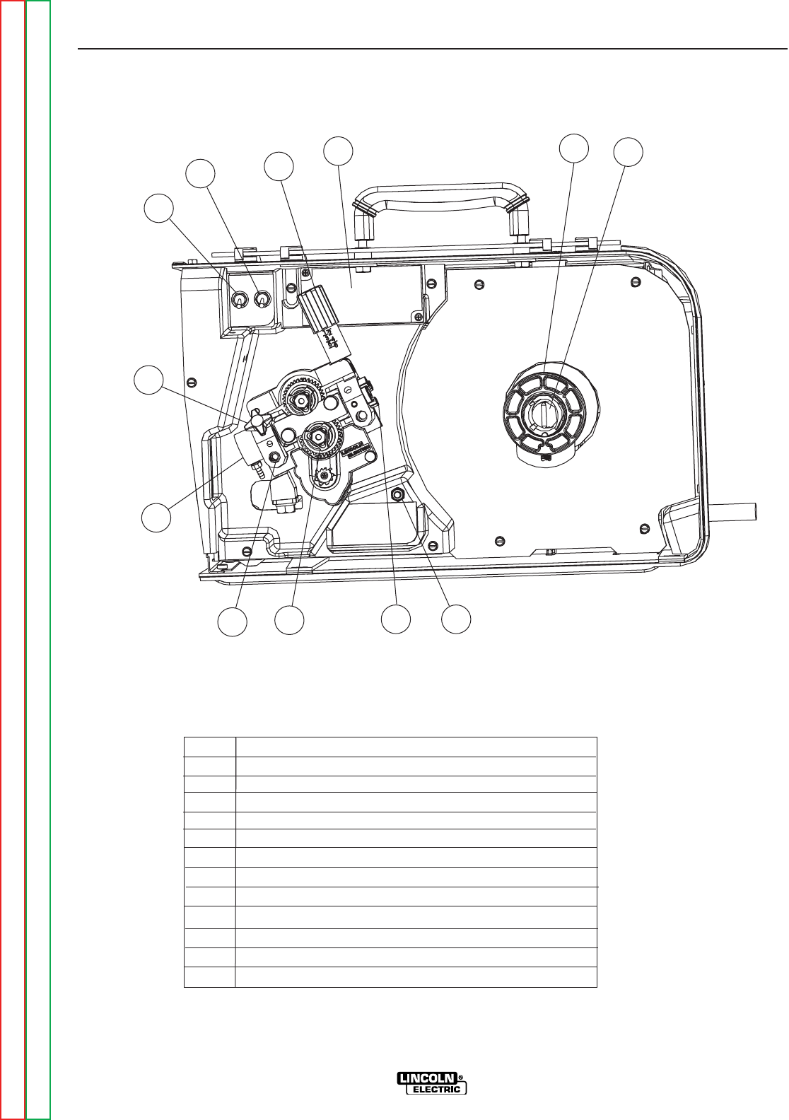
"'-+'%('-+(%,
1 2 Step Trigger Interlock Switch
2 CV / CC Switch
3 Pressure Adjustment Arm
4 Optional Timer Kit (See Accessories Section)
5 Spool Retainer
6 Spindle Brake
7 Gun Bushing
ITEM DESCRIPTION
1
9
8
7
6
3
2
8 Thumb Screw for securing the welding Gun
9 Socket Head Cap Screw for securing the Gun Bushing
45
10 Drive Hubs
12 Cold Feed Pushbutton
11 Inlet Wire Guide
11 12
10
" .+
Return to Section TOC Return to Section TOC Return to Section TOC Return to Section TOC
Return to Master TOC Return to Master TOC Return to Master TOC Return to Master TOC
()+-"('
%'S)+(
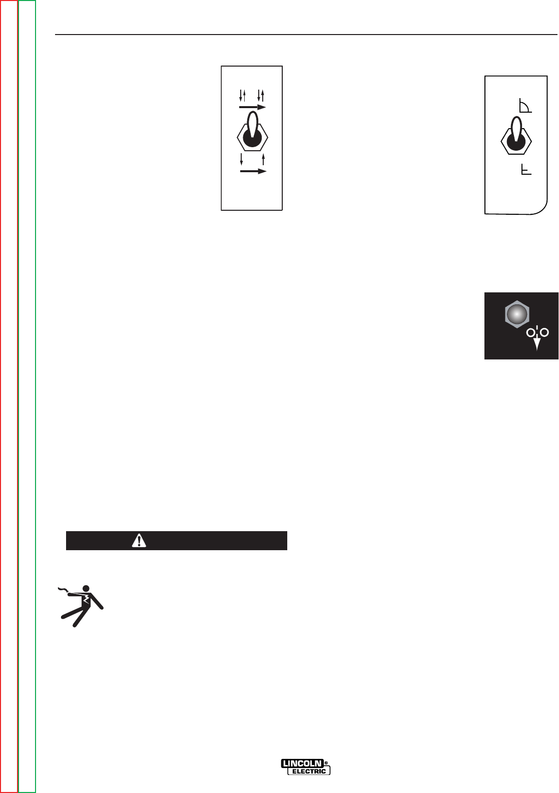
"'-+'%('-+(%,,+")-"('
(See Figure B.4)
,-)-+" + "'-+%($
,0"-!
The 2 Step - Trigger Interlock
switch changes the function of the
gun trigger. 2 Step trigger opera-
tion turns welding on and off in
direct response to the trigger.
Trigger Interlock operation allows
welding to continue when the trig-
ger is released for comfort on long
welds.
Place the toggle switch in the DOWN position for 2
Step operation or in the UP position for Trigger
Interlock operation.
,G8C-E<::8E
2 Step trigger operation is the most common. When
the gun trigger is pulled, the welding power source
energizes the electrode output and the wire feeder
feeds wire for welding. The power source and wire
feeder continue welding until the trigger is released.
-E<::8E"AG8E?B6>
Trigger Interlock operation provides for operator com-
fort when making long welds. When the gun trigger is
first pulled, the welding power source energizes the
output and the wire feeder feeds wire for welding. The
gun trigger is then released while the weld is made. To
stop welding, the gun trigger is pulled again, and when
it is released the welding power source output turns off
and the wire feeder stops feeding wire.
"9G;84E6:B8FBHGJ;<?8J8?7<A:J<G;
GE<::8E <AG8E?B6> BC8E4G<BA G;8 8?86
GEB78 BHGCHG 9EB@ G;8 J8?7<A: CBJ8E
FBHE68E8@4<AF8A8E:<M874A7G;8J<E8
98878EJ<??6BAG<AH8GB9887 J<E8 HAG<?
G;8 :HA GE<::8E <F 4:4<A CH??87 4A7
G;8AE8?84F87
/,0"-!
(See Figure B.4)
The CV/CC switch sets the wire
feed speed control method for the
wire feeder.
In the CV position, the wire feed
speed remains constant during
welding. A steady arc voltage is
regulated by the power source by
adjusting the arc current.
In the CC position, the wire feed
speed varies during welding. The
arc length is maintained by chang-
ing the wire feed speed.
(%).,!.--('
(See Figure B.4)
When cold feeding, the wire drive
will feed electrode but neither the
power source nor the gas solenoid
will be energized. Adjust the speed
of cold feeding by rotating the WFS
knob. Cold feeding, or “cold inching”
the electrode is useful for threading
the electrode through the gun.
CV
CC
.-"('
Return to Section TOC Return to Section TOC Return to Section TOC Return to Section TOC
Return to Master TOC Return to Master TOC Return to Master TOC Return to Master TOC

()+-"('
%'S)+(
()-"('%)+%(0.+'$'
)(,-%(0-"&+$"- $
The preflow, Burnback and Postflow Timer Kit gives
you control over the shielding gas at the beginning and
end of the weld and prepares the end of the wire for
the next arc start. Additional shielding gas protection
is often required when welding aluminum, stainless
steel or exotic alloys.
'(- When stitch welding, set the postflow time to
maximum for best results.
)E89?BJ-<@8E
The preflow timer range is OFF to 10 seconds.
Preflow time is the time delay from when the trigger is
pulled to when the wire starts to feed and is energized.
Preflow is used purge the welding gun with shielding
gads and helps to maximize porosity at the start of the
weld.
HEA546>-<@8E
The Burnback timer range is OFF to 0.25 seconds.
The burnback timer controls the additional amount of
time the power source output remains ON after the
wire drive has stopped feeding wire. Burnback adjust-
ment prevents the wire from sticking to the weld at the
end of a weld and helps to condition the wire for the
next weld.
To set the burnback time, adjust the knob to approxi-
mately 0.03 seconds and then decrease or increase
the time as desired.
)BFG9?BJ-<@8E
The postflow timer range is OFF to 10 seconds.
Postflow is the time from when the power source out-
put turns OFF until the postflow timer expires. Use
postflow to protect the weld while the weld cools.
Return to Section TOC Return to Section TOC Return to Section TOC Return to Section TOC
Return to Master TOC Return to Master TOC Return to Master TOC Return to Master TOC
()+-"('
%'S)+(
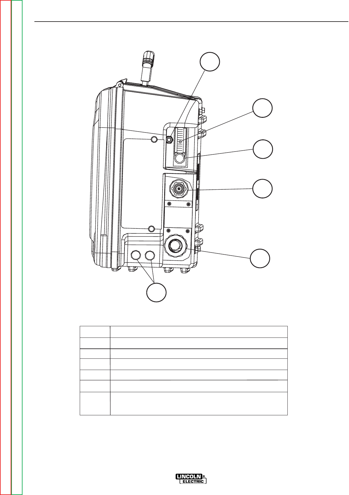
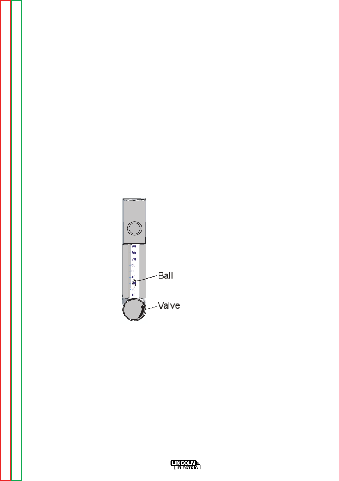
++('-+(%,
" .+
1 Gas Purge Pushbutton
2 Flow Meter Ball
4 Shielding Gas Inlet
3 Flow Meter Valve
6 Optional Water cooled gun
connections
5 Electrode Lead
ITEM DESCRIPTION
1
2
3
4
5
6
Return to Section TOC Return to Section TOC Return to Section TOC Return to Section TOC
Return to Master TOC Return to Master TOC Return to Master TOC Return to Master TOC
()+-"('
%'S)+(
,).+ ).,!.--('
The gas solenoid valve will energize but neither the
power source output nor the drive motor will be turned
on. The Gas Purge switch is useful for setting the
proper flow rate of shielding gas and for purging the
lines.. Flow meters should always be adjusted while
the shielding gas is flowing.
%(0&-+
The flowmeter shows the flow rate of shielding gas and
has a valve to adjust the flow. The flow meter is scaled
for CO2, Ar, and Ar/CO2blends. The middle of the ball
indicates the flow rate of shielding gas.
Adjust the flow rate while depressing the GAS PURGE
switch by turning the valve at the bottom of the meter.
Most weld procedures require 25-40 scfh (11.8 - 18.9
lpm) for sufficient shielding gas coverage. Gun angle,
nozzle diameter, joint configuration and wind condi-
tions may effect the amount of shielding gas required.
When using a wire feeder with
a flow meter, adjust the regula-
tor at the shield gas bottle or
supply to a flow rate that is
higher than the flow rate indi-
cated on the feeder flow meter.
Note that most regulators are
calibrated based upon having
low restrictions on the outlet.
The valve on the feeder flow
meter creates a high restric-
tion and may cause errors in
the readings at the supply reg-
ulator. Set the gas flow rate
using the feeder flow meter
reading and not the supply
regulator reading.
,! %<G8E&<A
10 4.7
20 9.4
30 14.2
40 18.9
50 23.6
60 28.3
70 33.1
80 37.8
)(0+.),*.'
For feeders with analog voltmeters, the thermal LED
and the Polarity LED will light breifly during power-up.
If the gun trigger is activated during power up, the feed-
er will not operate unless the gun trigger is released
and re-activated.
Return to Section TOC Return to Section TOC Return to Section TOC Return to Section TOC
Return to Master TOC Return to Master TOC Return to Master TOC Return to Master TOC


-%(('-'-,,,(+",,-"('
%'S)+(
668FFBE<8F
Factory Installed Equipment . . . . . . . . . . . . . . . . . . . . . . . . . . . . . . . . . . . . . . . . . . . . . . . . . . . . . . . . . . . .C-2
Accessories . . . . . . . . . . . . . . . . . . . . . . . . . . . . . . . . . . . . . . . . . . . . . . . . . . . . . . . . . . . . . . . . . . . . . .C-3/C-5
Installation of the K590-6 Water Cooling Kit . . . . . . . . . . . . . . . . . . . . . . . . . . . . . . . . . . . . . . . . . . . . . . . .C-6
Return to Master TOC Return to Master TOC Return to Master TOC Return to Master TOC
,,(+",
%'S)+(
0"+-2)
Steel Wires:
Cored Wires:
Aluminum Wires:
%-+(,"3
.023-.030 (0.6-0.8mm)
.035 (0.9mm)
.045 (1.2mm)
.052 (1.4mm)
1/16 (1.6mm)
.035,.045 (0.9, 1.2mm)
.040 (1.0mm)
.030-.035" (0.8-0.9mm)
.040-.045" (1.0-1.2mm)
.052" (1.4mm)
1/16" (1.6mm)
.068-.072" (1.7-1.8mm)
5/64" (2.0mm)
3/32” (2.4mm)
.035" (0.9 mm)
.040" (1.0mm)
3/64" (1.2mm)
1/16" (1.6mm)
$)$"-
KP1696-030S
KP1696-035S
KP1696-045S
KP1696-052S
KP1696-1/16S
KP1696-1
KP1696-2
KP1697-035C
KP1697-045C
KP1697-052C
KP1697-1/16C
KP1697-068
KP1697-5/64
KP1697-3/32
KP1695-035A
KP1695-040A
KP1695-3/64A
KP1695-1/16A
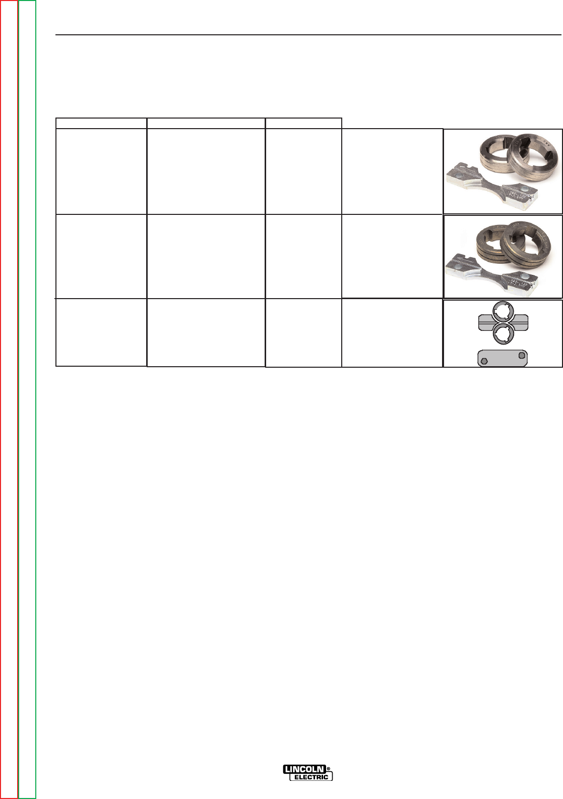
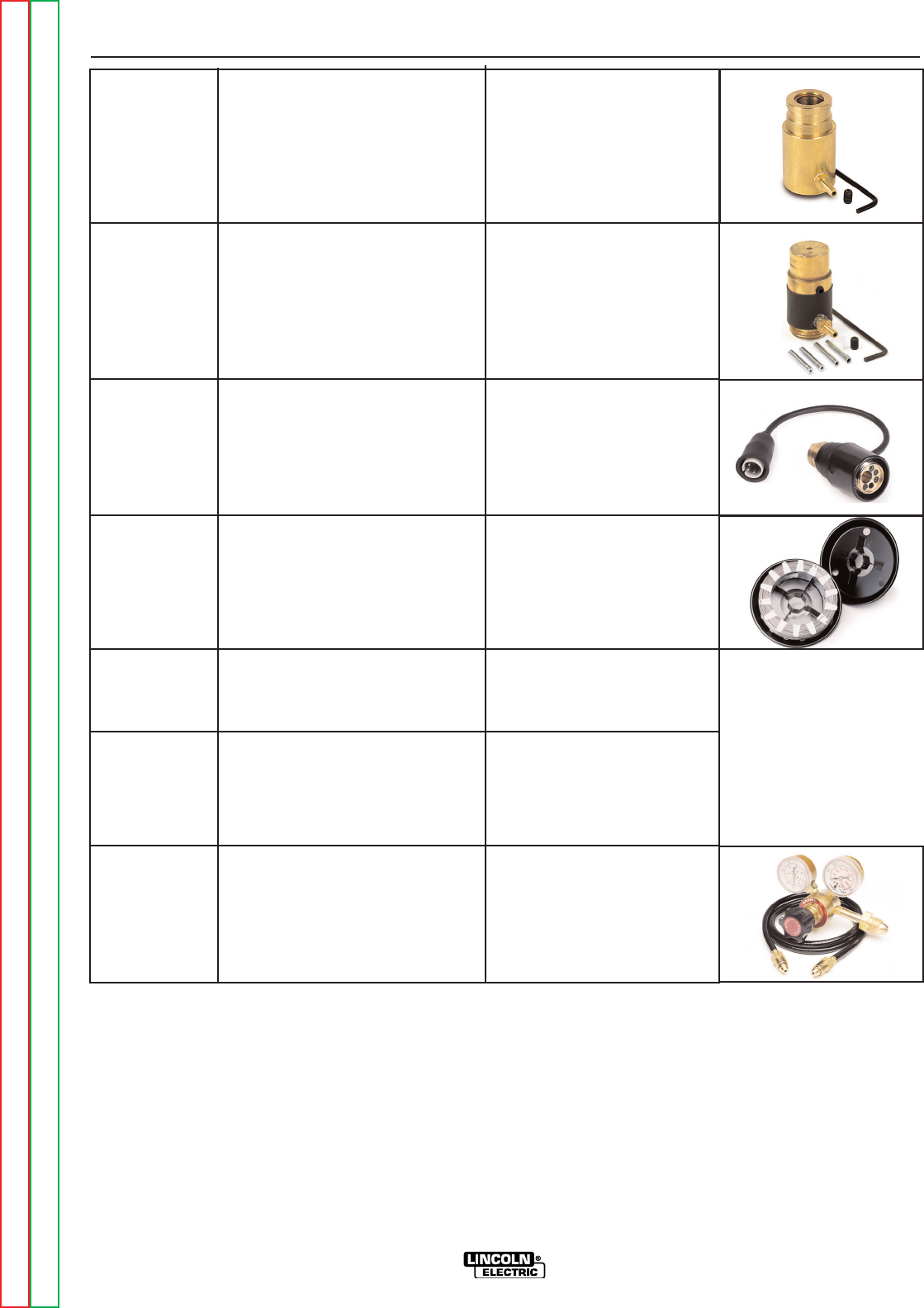
-(+2"',-%%*.")&'-
• K1500-2 Gun Receiver Bushing.
Includes: 2 V groove
drive rolls and inner
wire guide.
Includes: 2 Knurled
drive rolls and inner
wire guide.
Includes: 2 polished
U groove drive rolls,
outer wire guide and
inner wire guide.
+"/+(%%$"-,
Return to Section TOC Return to Section TOC Return to Section TOC Return to Section TOC
Return to Master TOC Return to Master TOC Return to Master TOC Return to Master TOC
,,(+",
%'S)+(
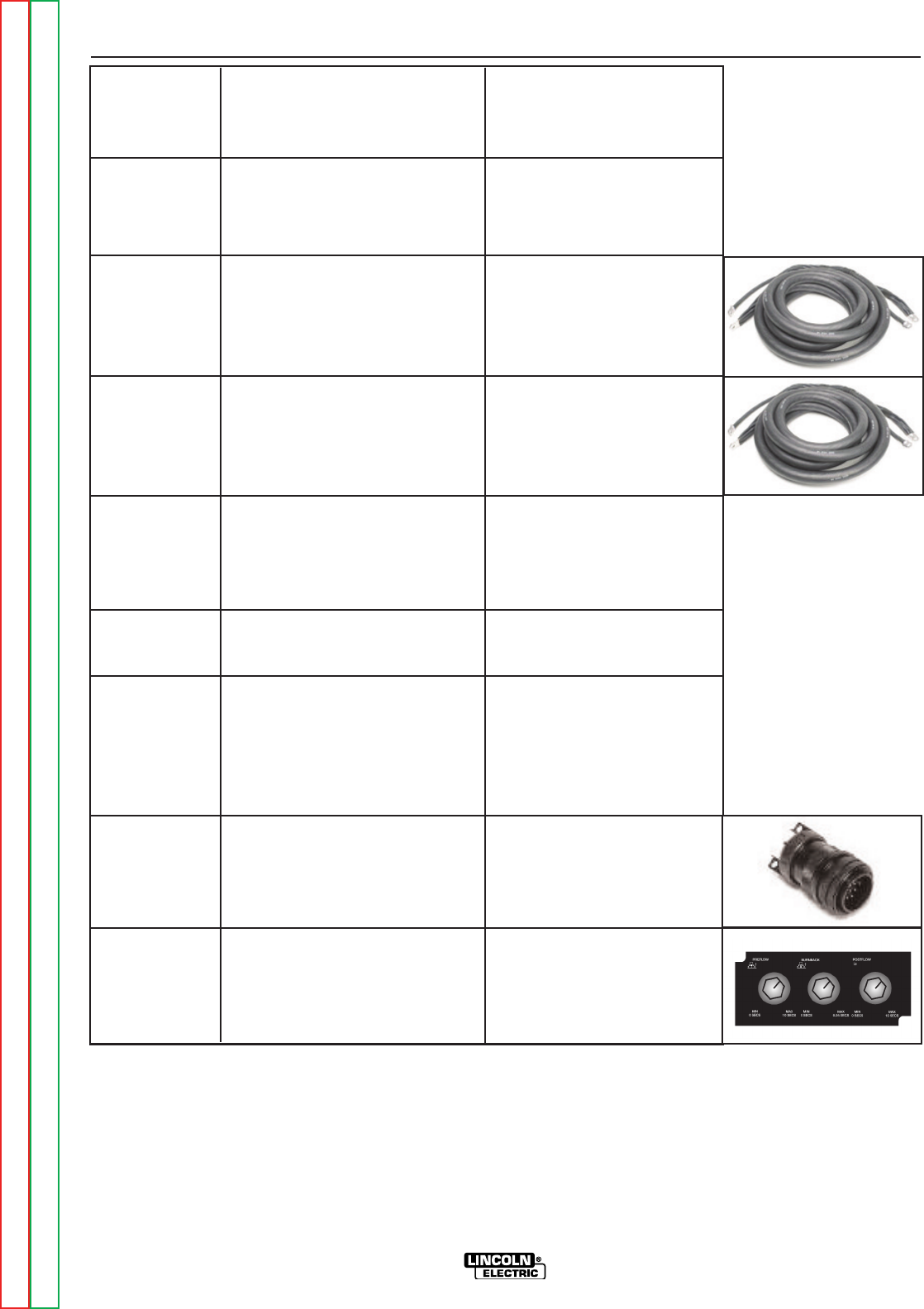
K2596-1
K2596-2
K1796-xx
K2593-xx
K1803-1
K1840-xx
K1842-xx
K484
K2330-2
Aluminum Case
Plastic Case
AWG 1/0 Co-Axial Power Cable
AWG #1 Coaxial Power Cable
Work and Feeder Cables Package
Weld Power Cable, Twist-Mate to
Lug
Weld Power Cable, Lug to Lug
Jumper Plug Kit
Timer Kit
Includes: a complete alu-
minum case. Decals, skids,
insulation and latches are all
preassembled.
Includes: a complete engi-
neered plastic case. Decals
and latches are all preassem-
bled.
Includes: 1/0 Coaxial weld
cable of length "xx". Ends of
the weld cable have lug con-
nections. Use for Pulse weld-
ing.
Includes: AWG #1 Coaxial
weld cable of length "xx".
Ends of the weld cable have
lug connections. Use for
Pulse or STT™ welding.
Includes: Twist-Mate to Lug
2/0 cable 14' (1.2m) long with
Ground Clamp, and Twist-
Mate to Lug 2/0 Cable 9'
(2.7m) long.
Includes: Twist-Mate to Lug,
1/0 cable of length "xx".
Includes: Lug to Lug, 3/0
Cable of length "xx" for
lengths up to 60' (18.3m).
Lug to Lug, 4/0 Cable of
length "xx" for lengths greater
than 60' (18.3m).
Includes: 14 pin circular con-
nector with jumper for leads 2-
4. For use in power sources
for turning the weld terminals
"ON" at all times.
Includes Panel and harness.
Provides adjustable Preflow,
post flow and Burnback.
Return to Section TOC Return to Section TOC Return to Section TOC Return to Section TOC
Return to Master TOC Return to Master TOC Return to Master TOC Return to Master TOC
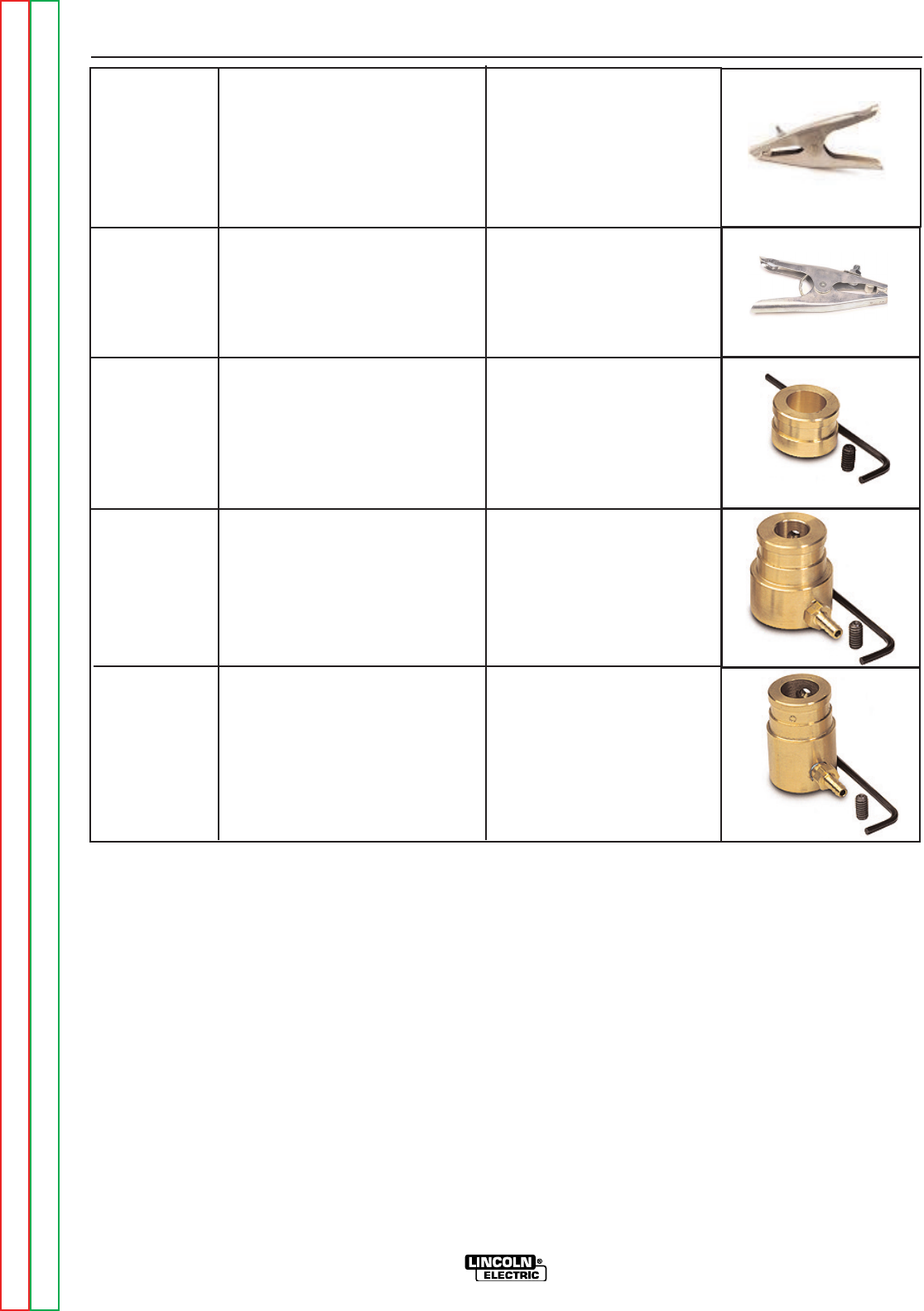
,,(+",
%'S)+(
K910-1
K910-2
K1500-1
K1500-2
K1500-3
Ground Clamp
Ground Clamp
Gun Receiver Bushing (for guns
with K466-1 Lincoln gun connec-
tors; Innershield and Subarc guns)
Gun Receiver Bushing (for guns
with K466-2, K466-10 Lincoln gun
connectors; Magnum 200/300/400
guns and compatible with Tweco®
#2-#4)
Gun Receiver Bushing (for guns
with K613-7 Lincoln gun connec-
tors; Magnum 550 guns and com-
patible with Tweco® #5)
Includes: One 300 Amp
Ground Clamp.
Includes: One 500 Amp
Ground Clamp.
Includes: Gun receiver bush-
ing, set screw and hex key
wrench.
Includes: Gun receiver bush-
ing with hose nipple, set
screw and hex key wrench.
Includes: Gun receiver bush-
ing with hose nipple, set
screw and hex key wrench.
Return to Section TOC Return to Section TOC Return to Section TOC Return to Section TOC
Return to Master TOC Return to Master TOC Return to Master TOC Return to Master TOC
,,(+",
%'S)+(
K1500-4
K1500-5
K489-7 *
K435
K468
K590-6
K586-1
Gun Receiver Bushing (for gun
with K466-3 Lincoln gun connec-
tors; compatible with Miller®
guns.)
Gun Receiver Bushing (compatible
with Oxo® guns.)
Gun Receiver Bushing (for Lincoln
Fast-Mate guns.)
Spindle Adapter, for mounting 14
lb. (6.4 kg) Innershield Coils on 2
in (51 mm) spindles.
Spindle Adapter, for mounting 8in
(203mm) diameter spools on 2 in
(51 mm) spindles.
Water Connection Kit (for
European and Control cable mod-
els only)
Deluxe Adjustable Gas Regulator
Includes: Gun receiver bush-
ing with hose nipple, set
screw and hex key wrench.
Includes: Gun receiver bushing
with hose nipple, 4 guide tubes,
set screw and hex key wrench.
Includes: Gun receiver bushing
with trigger connector.
Includes: Spindle Adapter made
from 2 coil retainers. (Electrode
not included.)
Includes: 2 Spindle Adapters,
one for 2" wide spools and the
other for 3" wide spools.
Includes: 2 hoses with female
quick connectors at each end, 2
male connectors for 3/16" ID
hose, 2 male connectors for _" ID
hose, and mounting hardware.
Includes: Deluxe Gas Regulator
for Mixed Gases, Adapter for
CO2 and 1
0' (3.0m) Hose.
* Not compatible with K2613-5 & K2613-7 feeders (Codes 11746, & 11747)
Return to Section TOC Return to Section TOC Return to Section TOC Return to Section TOC
Return to Master TOC Return to Master TOC Return to Master TOC Return to Master TOC
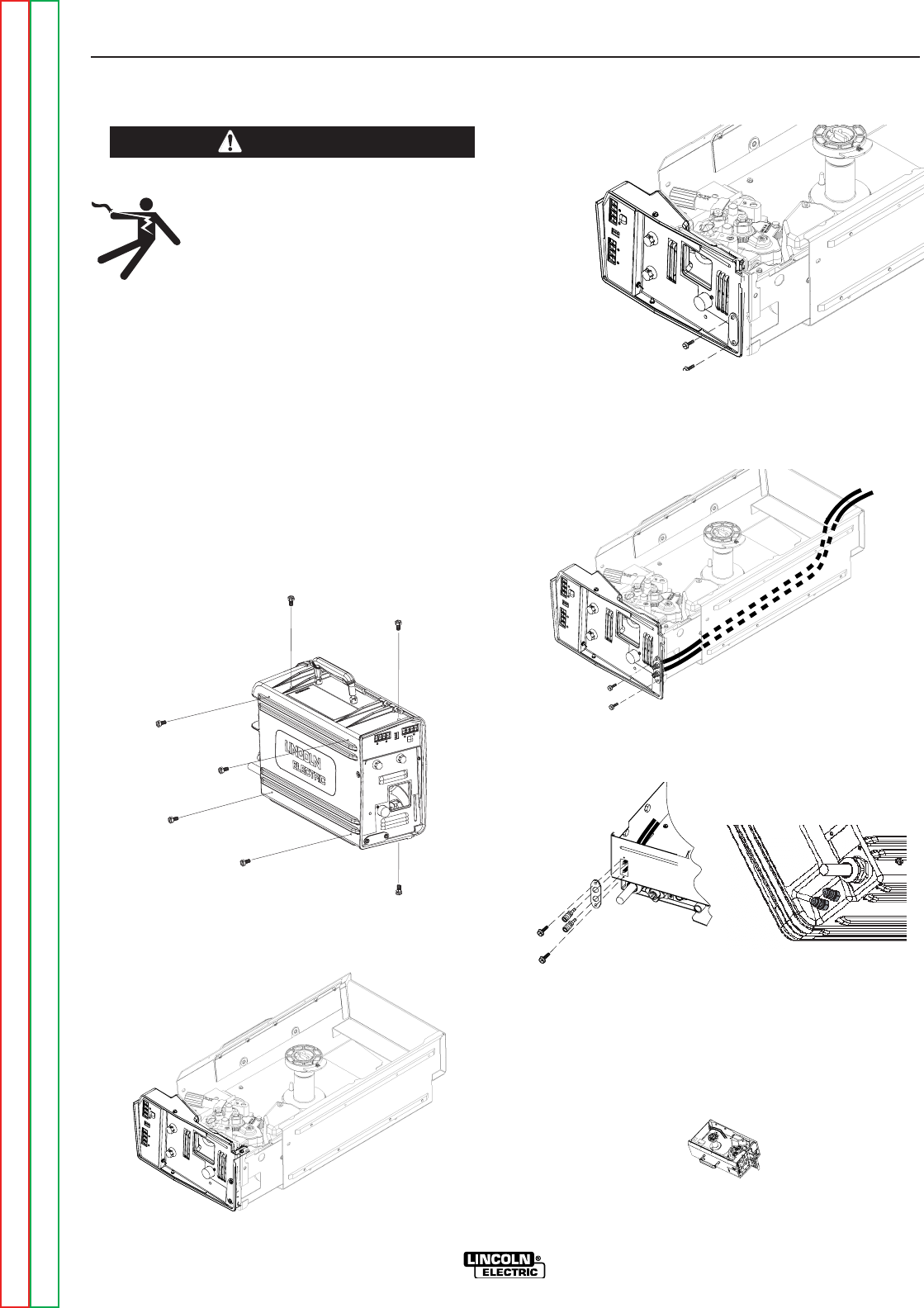
,,(+",
%'S)+(
"',-%%-"(' ( -! $ 0-+
((%"' $"-
%-+",!($64A><??
R-HEAG;8<ACHGCBJ8E(4GG;87<F
6BAA86G FJ<G6; 589BE8 JBE><A: BA
G;<F8DH<C@8AG
RBABGGBH6;8?86GE<64??L;BGC4EGF
R(A?L DH4?<9<87 C8EFBAA8? F;BH?7
<AFG4??HF8BEF8EI<68G;<F8DH<C@8AG
The K590-6 components are rated up to 70 psi (5 bar)
and 158°F (70°C). Use a coolant fluid that is compati-
ble with the water cooler and the gun.
Tools required:
• 3/8" wrench
• 5/16" nut driver
• medium flat bladed screw driver
• cutting tool
1. Turn power off at the welding power source.
2. Remove the screws securing the case to the inner
module using a 3/8" wrench.
3. Remove the module from the case by lifting the front
of the module approximately .25" (6 mm) and then
sliding forward.
4. Use a 5/16" nut driver to remove the screws holding
the water cooling cover on the case front of the inner
module and on the rear of the case.
5. Install the fitting and hose assembly to the case
front. Route the hoses along the bottom of the inner
module and out through the cutout of the cover.
Slide the module back into the case.
6. Secure the module to the case with the screws.
(Shown in Step 2)
7. Install the fitting assembly to the rear of the case
8. Slide the hose clamps on to the hoses. Trim the
hoses to length so that they lay flat on the case bot-
tom. Slide hose clamps on the hose. Slide the hoses
on to the fittings on the case rear and secure with
the hose clamps.
0+'"'
jjo
oee w
waass hhe
er
ree 22000
011
jjooee wwa
ass hheerre
e 22000
011
ALUMINUM CASE
PLASTIC CASE
Return to Section TOC Return to Section TOC Return to Section TOC Return to Section TOC
Return to Master TOC Return to Master TOC Return to Master TOC Return to Master TOC

-%(('-'-,&"'-'',-"('
%'S)+(
&4<AG8A4A68
Safety Precautions . . . . . . . . . . . . . . . . . . . . . . . . . . . . . . . . . . . . . . . . . . . . . . . . . . . . . . . . . . . . . . . . . . . .D-2
Routine Maintenance . . . . . . . . . . . . . . . . . . . . . . . . . . . . . . . . . . . . . . . . . . . . . . . . . . . . . . . . . . . . . . . . . .D-2
Periodic Maintenance . . . . . . . . . . . . . . . . . . . . . . . . . . . . . . . . . . . . . . . . . . . . . . . . . . . . . . . . . . . . . . . . . .D-2
Calibration Specification . . . . . . . . . . . . . . . . . . . . . . . . . . . . . . . . . . . . . . . . . . . . . . . . . . . . . . . . . . . . . . . .D-2
Flow Meter Validation . . . . . . . . . . . . . . . . . . . . . . . . . . . . . . . . . . . . . . . . . . . . . . . . . . . . . . . . . . . . . . . . . .D-2
Wire Feed Speed Validation . . . . . . . . . . . . . . . . . . . . . . . . . . . . . . . . . . . . . . . . . . . . . . . . . . . . . . . . . . . .D-3
Major Component Location . . . . . . . . . . . . . . . . . . . . . . . . . . . . . . . . . . . . . . . . . . . . . . . . . . . . . . . . . . . . .D-4
Return to Master TOC Return to Master TOC Return to Master TOC Return to Master TOC

&"'-''
%'S)+(
%-+",!($64A><??
R B ABG BC8E4G8 J<G; 6BI8EF
E8@BI87
R -HEA B99 CBJ8E FBHE68 589BE8
<AFG4??<A:BEF8EI<6<A:
R B ABG GBH6; 8?86GE<64??L ;BG
C4EGF
R-HEA G;8 <ACHG CBJ8E GB G;8 J8?7<A: CBJ8E
FBHE68B994GG;89HF85BK589BE8JBE><A:<AG;8
G8E@<A4?FGE<C
R(A?L DH4?<9<87 C8EFBAA8? F;BH?7 <AFG4?? HF8 BE
F8EI<68G;<F8DH<C@8AG
0+'"'
,-2)+.-"(',
+(.-"'&"'-''
• Check weld cables and gas hoses for cuts.
• Clean and tighten all weld terminals.
)+"("&"'-''
• Clean drive rolls and inner wire guide and replace if
worn.
• Blow out or vacuum the inside of the feeder.
%"+-"(',)""-"('
The voltmeter and flow meter are not calibrated and
are for reference purposes only.
/B?G@8G8E/4?<74G<BA6EBFFG;8E6A4?B:&8G8E
&B78?F
Tools required:
• DC voltmeter reference standard
• Constant voltage DC welding power source with
adjustable no-load voltage (DC-400, V-350, CV-400
or equivalent).
To verify the analog voltmeter accuracy:
1. Turn power OFF.
2. Connect the LN-25™ PRO to the constant voltage
DC welding power source. The work lead of the
LN-25™ PRO must be connected to the work ter-
minal of the power source.
3. Connect the reference voltmeter between the brass
block of the LN-25™ PRO and the work lead.
4. Turn power ON.
5. Energize the output circuit of the power source.
Adjust the power source output to 20±1 VDC as
measured on the reference meter.
6. Verify that LN-25™ PRO voltmeter reads between
19 and 21 volts.
If the voltmeter reading is out of range, check for loose
connections or replace the voltmeter. There is no cal-
ibration adjustment for the LN-25™ PRO voltmeter.
?BJ&8G8E/4?<74G<BA
-BB?FE8DH<E87
• Flow meter reference standard.
• Constant voltage DC welding power source (DC-
400, V-350, CV-400 or equivalent).
To verify the flow meter accuracy:
1. Turn power OFF.
2. Connect the LN-25™ PRO to the constant voltage
DC welding power source. The work lead of the
LN-25™ PRO must be connected to the work ter-
minal of the power source.
3. Connect a supply of CO2 to the wire feeder. Do not
exceed the maximum inlet pressure of the wire
feeder.
4. Disconnect the shielding gas hose that connects to
the gun bushing.
5. Connect the shielding gas hose to flow meter refer-
ence standard.
6. Orient the LN-25™ PRO in a vertical position.
7. Turn power ON.
8. Adjust the flow meter on the LN-25™ PRO to 40
scfh while pressing the GAS PURGE button.
9. Measure the gas flow with the calibrated flow meter
while pressing the GAS PURGE button.
10. The measured flow rate should be between 35
and 45 scfh.
The LN-25™ PRO flow meter cannot be calibrated. If
the flow meter reads incorrectly, check for leaks or
ki
nks in the gas hose. Replace the flow meter if neces-
sary.
Return to Section TOC Return to Section TOC Return to Section TOC Return to Section TOC
Return to Master TOC Return to Master TOC Return to Master TOC Return to Master TOC
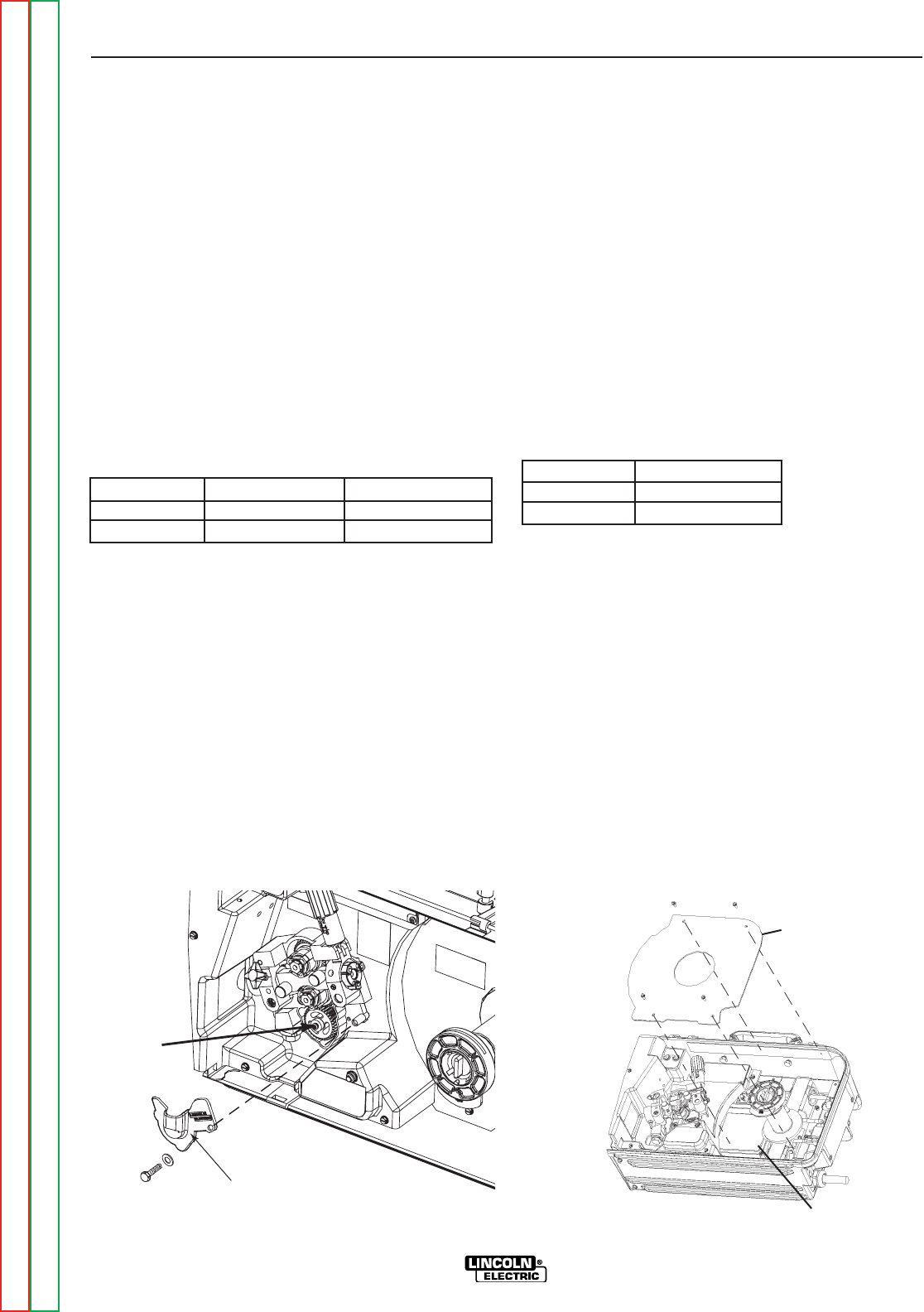
&"'-''
%'S)+(
0<E8887,C887/4?<74G<BA
(See Figure D.1)
Calibration of the LN-25™ PRO may be required when
the p.c. board, wire feed speed potentiometer or motor is
replaced or serviced. Calibration matches the scale on
the name plate to the actual wire feed speed.
Tools required:
• RPM meter
• Constant voltage DC welding power source (DC-400,
V-350, CV-400 or equivalent)
• 7/16" open end wrench
To verify if calibration is necessary:
1. Turn power OFF.
2. Set the wire feed speed per the table.
&B78?:84E<A: 0<E8887,C887668CG45?8+4A:8
Normal Speed 400 in/min 69 - 77 rpm
Extra Torque 150 in/min 25 - 31 rpm
3. Remove the plastic cover from the lower portion of the
wire drive with a 7/16" wrench.
4. Connect the LN-25™ PRO to the constant voltage DC
welding power source. The work lead of the LN-25™
PRO must be connected to the work terminal of the
power source.
5. Turn power ON.
6. Measure the motor rpm when the COLD FEED button
is pressed.
7. Verify the rpm is within the acceptable range.
-B6;4A:8G;8J<E89887FC88764?<5E4G<BA
(See Figure D.2)
Tools required:
• 5/16" nut driver
• RPM meter
• Shorting plug. LE CO.part # S18250-982 - The short-
ing plug shorts pins 4 & 8 of connector J3 on the Control
P.C. Board. J3 is an 8 pin Molex connector.
1. Turn power OFF.
2. Remove the 4 screws holding the rear cover inside the
feeder and remove the cover.
3. Open the idle arm.
4. Set the wire feed speed per the table.
&B78?:84E<A: 0<E8887,C887
Normal Speed 400 in/min
Extra Torque 150 in/min
5. Connect the LN-25™ PRO to the constant voltage DC
welding power source. The work lead of the LN-25™
PRO must be connected to the work terminal of the
power source.
6. Turn power ON.
7.
Insert the shorting plug into connector J3 on the Control
P.C. Board. The shorting plug shorts pins 4 & 8.
8. Remove the shorting plug.
9. Turn power OFF.
10. Replace the cover and secure with the screws.
COVER
MOTOR
SHAFT
" .+ " .+
(/+
)(+
Return to Section TOC Return to Section TOC Return to Section TOC Return to Section TOC
Return to Master TOC Return to Master TOC Return to Master TOC Return to Master TOC
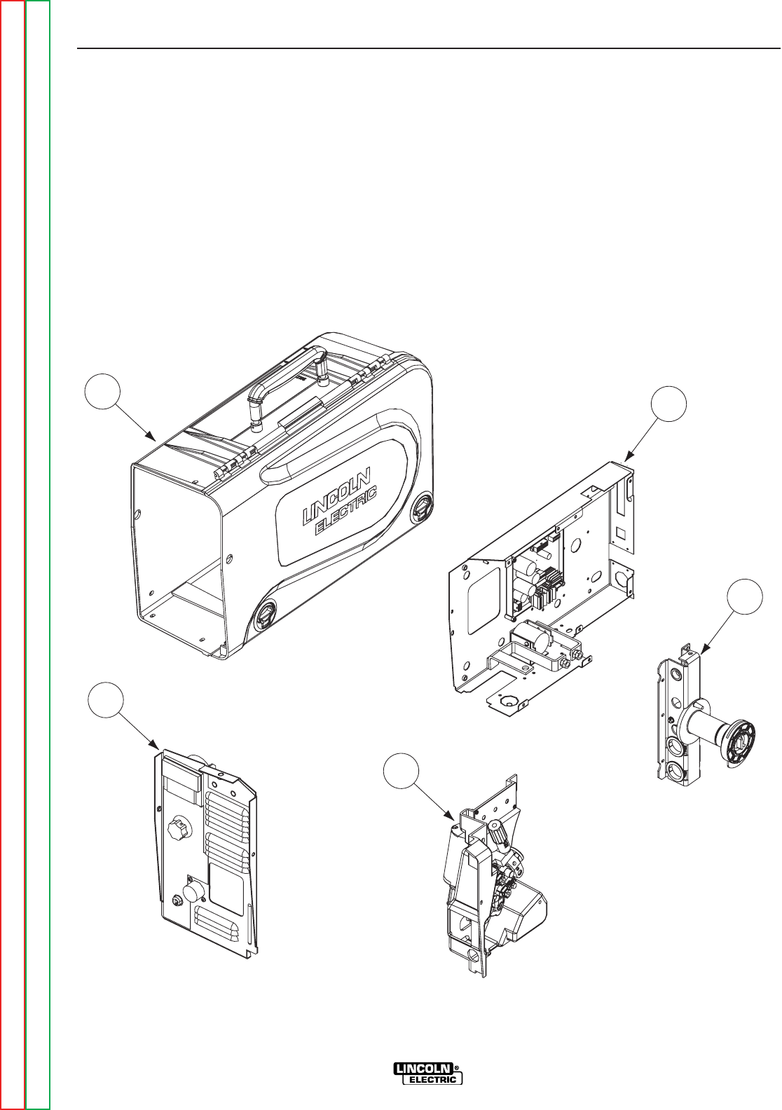
5522
11
44
33
&"'-''
%'S)+(
1. FRONT PANEL ASSEMBLY
2. CONTROL BOX ASSEMBLY
3. SPINDLE & MAST ASSEMBLY
4. WIRE DRIVE ASSEMBLY
5. CASE ASSEMBLY
" .+&#(+(&)(''-%(-"('
Return to Section TOC Return to Section TOC Return to Section TOC Return to Section TOC
Return to Master TOC Return to Master TOC Return to Master TOC Return to Master TOC
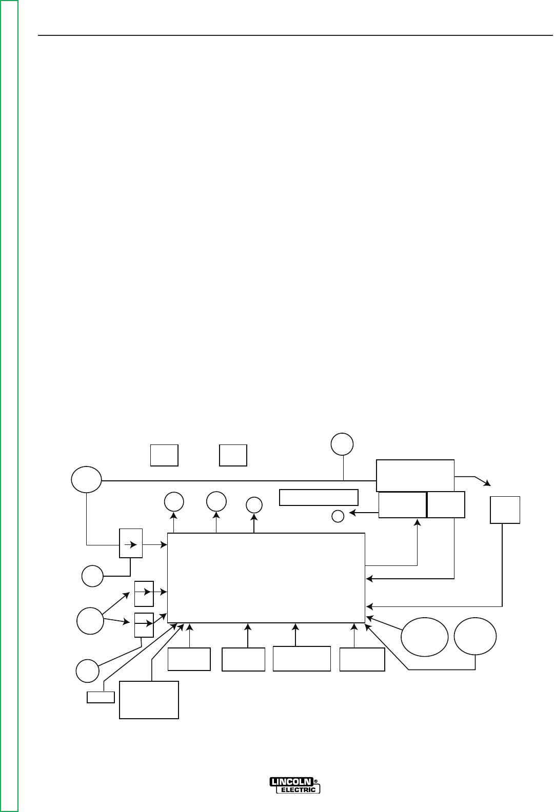
-%(('-'-,-!(+2(()+-"(',-"('
%'S)+(
-;8BELB9(C8E4G<BA
General Description . . . . . . . . . . . . . . . . . . . . . . . . . . . . . . . . . . . . . . . . . . . . . . . . . . . . . . . . . . . . . . . . . . .E-2
Input Power . . . . . . . . . . . . . . . . . . . . . . . . . . . . . . . . . . . . . . . . . . . . . . . . . . . . . . . . . . . . . . . . . . . . . . . . .E-3
Trigger Circuit . . . . . . . . . . . . . . . . . . . . . . . . . . . . . . . . . . . . . . . . . . . . . . . . . . . . . . . . . . . . . . . . . . . . . . . .E-3
Feedback and Control Circuits . . . . . . . . . . . . . . . . . . . . . . . . . . . . . . . . . . . . . . . . . . . . . . . . . . . . . . . . . . .E-4
Optional Circuits . . . . . . . . . . . . . . . . . . . . . . . . . . . . . . . . . . . . . . . . . . . . . . . . . . . . . . . . . . . . . . . . . . . . . .E-5
Digital Display Board . . . . . . . . . . . . . . . . . . . . . . . . . . . . . . . . . . . . . . . . . . . . . . . . . . . . . . . . . . . . . . . . . .E-5
" .+W%($%( "" +&
ELECTRODE
INPUT
CONTROL BOARD
FEEDPLATE
MOTOR TACH
67
CONTACTOR CURRENT TRANSDUCER
INPUT
SOLENOID
V M
POLARITY
TIMER OPTION
MOTOR
OVERLOAD
21
21
ARMATURE
TACH FEEDBACK
GUN TRIGGER
GUN
RUN IN
DIGITAL
DISPLAY
BOARD
COLD
FEED
CC
CV
TRIGGER
INTERLOCK
GAS
PURGE
WIRE
SPEED
REMOTE
VOLTAGE
14 PIN AMPHENOL
1
Return to Master TOC Return to Master TOC Return to Master TOC Return to Master TOC
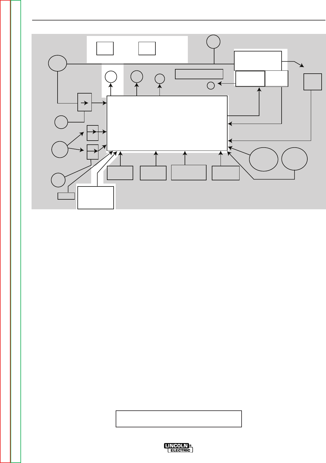
-!(+2(()+-"('
%'S)+(
'+%,+")-"('
Several models of the LN-25™ PRO are offered to best
meet the individual welders needs. The Extra Torque
model features additional torque for reliable feeding of
large diameter FCAW wire. The standard and control
cable models feature wire drive gearing for optimal per-
formance with both FCAW and GMAW wires of com-
mon sizes. All the models include a gas solenoid and
flow meter for the flexibility to run most wire processes.
Control Cable models also includes digital meters and
remote voltage control.
The plastic case is molded from high impact, flame
retardant plastic for durability and low weight. The
patent pending design keeps the internal components
protected and dry.
" .+W '+%,+")-"('
The heart of the LN-25™ PRO is a 2 roll MAXTRAC
wire drive system. The patented features on the wire
drive offer tool-less changing of the drive rolls and wire
guides for quick changeovers. A tachometer controlled
motor powers the patent pending drive rolls for smooth,
steady feeding without slippage.
With only one p.c. board, the LN-25™ PRO is designed
to be simple, reliable and easy to service. The p.c.
board is manufactured with Lincoln’s industry leading
environmental design protection which involces mount-
ing the board in a plastic tray and potting it with epoxy.
With a 325 amp, 100% duty cycle rating, these feeders
are ready for heavy duty welding.
NOTE: Unshaded areas of Block Logic
Diagram are the subject of discussion
ELECTRODE
INPUT
CONTROL BOARD
FEEDPLATE
MOTOR TACH
67
CONTACTOR CURRENT TRANSDUCER
INPUT
SOLENOID
V M
POLARITY
TIMER OPTION
MOTOR
OVERLOAD
21
21
ARMATURE
TACH FEEDBACK
GUN TRIGGER
GUN
RUN IN
DIGITAL
DISPLAY
BOARD
COLD
FEED
CC
CV
TRIGGER
INTERLOCK
GAS
PURGE
WIRE
SPEED
REMOTE
VOLTAGE
14 PIN AMPHENOL
1
Return to Section TOC Return to Section TOC Return to Section TOC Return to Section TOC
Return to Master TOC Return to Master TOC Return to Master TOC Return to Master TOC
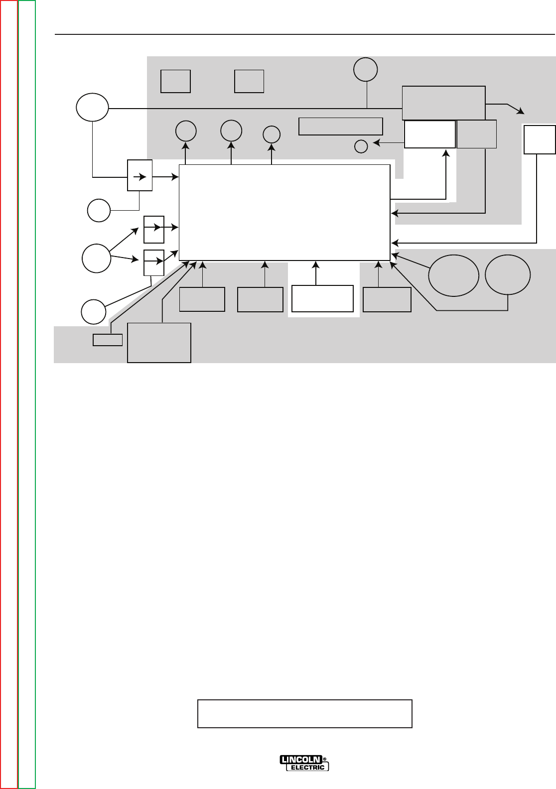
-!(+2(()+-"('
%'S)+(
NOTE: Unshaded areas of Block Logic
Diagram are the subject of discussion
"').-)(0+
The DC input voltage is applied from the power source
via the electrode cable and the work sensing lead on
the across the arc model. With the control cable model
24 to 42VDC is supplied from the power source via the
control cable and the work sense lead.
This voltage is applied through a bridge rectifier and an
analog voltmeter (across the arc), or digital meter (con-
trol cable) and then is supplied to the control board.
The control board the regulates and disperses the var-
ious supply voltages needed for machine operation.
" .+W"').-)(0+-+" +"+."-
-+" +Z"+."-
When the gun trigger is closed, the control board is sig-
naled to apply armature voltage to the drive motor and
to activate any auxiliary circuits that may be incorpo-
rated within the LN-25PRO.
Trigger interlock is used for long welds. When an arc
is established the trigger can be released. To stop
welding, the gun trigger is pulled again, and when it is
released the second time, the welding power source
output turns off and the wire speed stops.
ELECTRODE
INPUT
CONTROL BOARD
FEEDPLATE
MOTOR TACH
67
CONTACTOR CURRENT TRANSDUCER
INPUT
SOLENOID
V M
POLARITY
TIMER OPTION
MOTOR
OVERLOAD
21
21
ARMATURE
TACH FEEDBACK
GUN TRIGGER
GUN
RUN IN
DIGITAL
DISPLAY
BOARD
COLD
FEED
CC
CV
TRIGGER
INTERLOCK
GAS
PURGE
WIRE
SPEED
REMOTE
VOLTAGE
14 PIN AMPHENOL
1
Return to Section TOC Return to Section TOC Return to Section TOC Return to Section TOC
Return to Master TOC Return to Master TOC Return to Master TOC Return to Master TOC
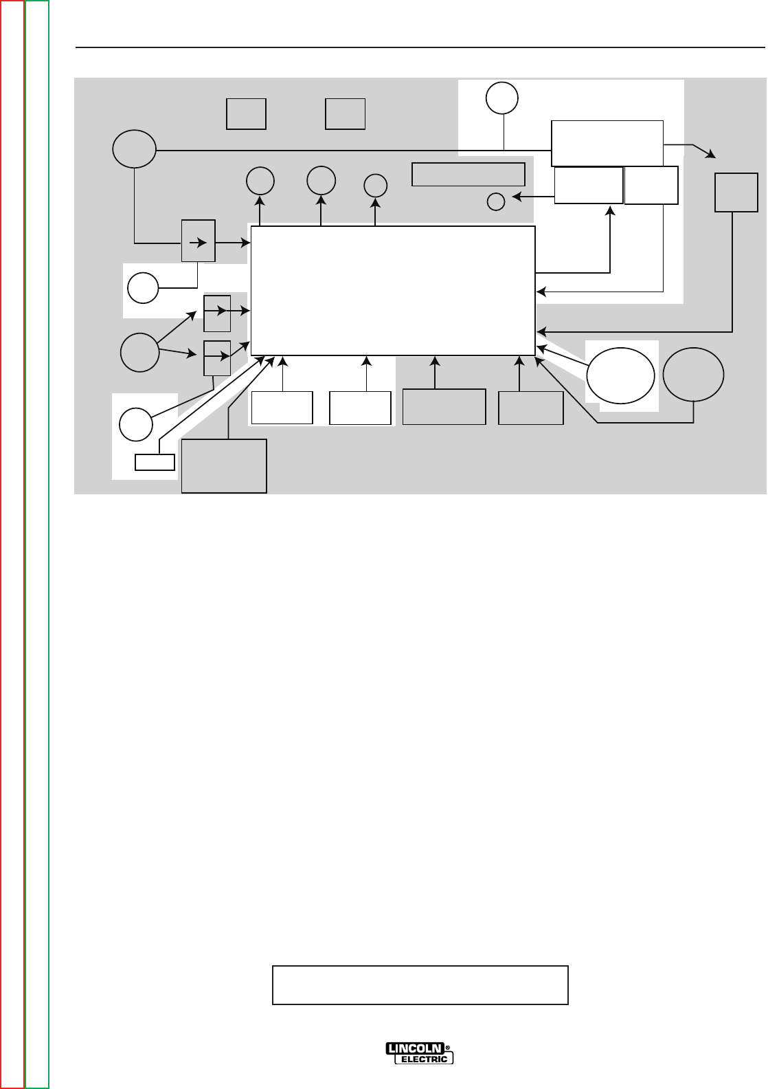
-!(+2(()+-"('
%'S)+(
NOTE: Unshaded areas of Block Logic
Diagram are the subject of discussion
$ ' ('-+(% "+
."-,
The wire speed pot provides command signal to the
control board indicating the desired wire speed. The
tachometer transforms the motor RPM to a digital fre-
quency that is fed back to the control board.
When operating in constant voltage (CV) mode, the
control board monitors the feedback signal, compares
it to the command signal and delivers the appropriate
voltage to the wire drive motor.
When operating in constant current (CC) mode, a vari-
able wire speed is desirable to compensate for the
varying arc voltages associated with the constant cur-
rent process. To accomplish this, the control board
monitors the command voltage, the feedback signal
from the tach and the arc voltage.
" .+W$('-+(%"+."-,
These three factors are monitored and compared, then
the appropriate armature voltage is applied to the wire
drive motor.
When the Run-in Switch is on, the wire speed is
reduced until an arc is struck. When it is off the run-in
wire speed is the same as the welding wire feed speed.
Pressing the cold feed button activates the drive rolls
but neither the power source nor the gas solenoid will
be activated.
ELECTRODE
INPUT
CONTROL BOARD
FEEDPLATE
MOTOR TACH
67
CONTACTOR CURRENT TRANSDUCER
INPUT
SOLENOID
V M
POLARITY
TIMER OPTION
MOTOR
OVERLOAD
21
21
ARMATURE
TACH FEEDBACK
GUN TRIGGER
GUN
RUN IN
DIGITAL
DISPLAY
BOARD
COLD
FEED
CC
CV
TRIGGER
INTERLOCK
GAS
PURGE
WIRE
SPEED
REMOTE
VOLTAGE
14 PIN AMPHENOL
1
Return to Section TOC Return to Section TOC Return to Section TOC Return to Section TOC
Return to Master TOC Return to Master TOC Return to Master TOC Return to Master TOC
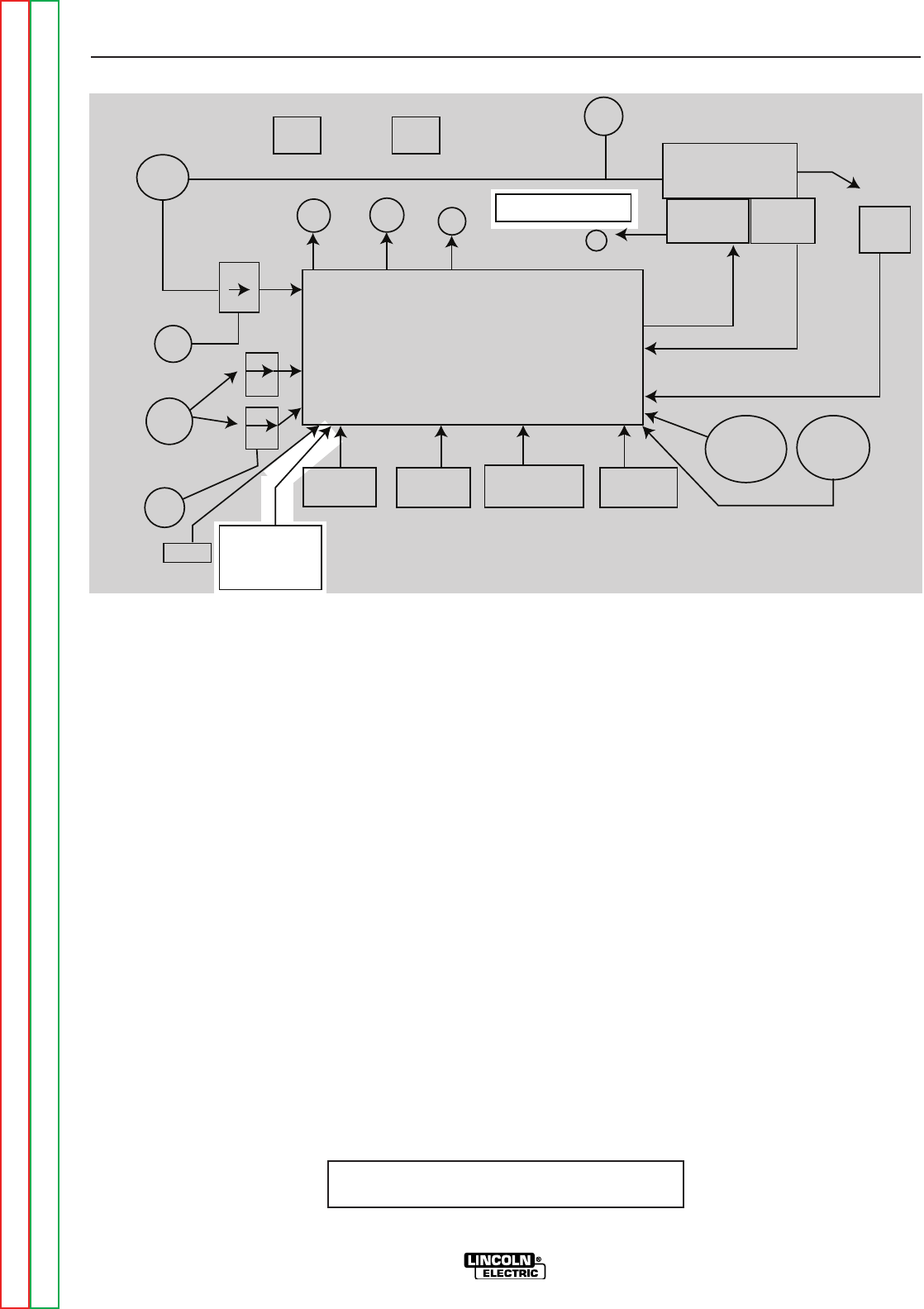
-!(+2(()+-"('
%'S)+(
" "-%",)%2(+
6BAGEB?645?8@B78?FBA?L
When the wire feeder is not welding, the left display
shows the wire feed speed. The default units are
“in/min” and may be changed to “m/min” through the
setup menu. During welding the left display shows the
average welding current, and will continue to hold the
last value for 5 seconds after the trigger is released.
When the wire feeder is in idle the right display shows
the preset voltage. This voltage will change with dif-
ferent power sources and can be changed through the
setup menu. During welding, the right display shows
the average welding voltage, and will hold the last
value for 5 seconds after the trigger is released.
" .+W()-"('%"+."-," "-%",)%2(+
()-"('%"+."-,
The preflow, burnback, and postflow timer kit gives
control over the shielded gas at the beginning and end
of the weld and prepares the end of the wire for the
next arc start.
The preflow timer range is zero to 10 seconds. Preflow
is used to purge the welding gun with shielding gas and
helps to minimize porosity at the start of a weld.
The burnback timer range is zero to 0.25 seconds.
Burnback controls the additional amount of time the
power source output remains on after the wire drive
has stopped feeding wire.
The postflow timer range is zero to 10 seconds. Use
postflow to protect the weld while it cools.
NOTE: Unshaded areas of Block Logic
Diagram are the subject of discussion
ELECTRODE
INPUT
CONTROL BOARD
FEEDPLATE
MOTOR TACH
67
CONTACTOR CURRENT TRANSDUCER
INPUT
SOLENOID
V M
POLARITY
TIMER OPTION
MOTOR
OVERLOAD
21
21
ARMATURE
TACH FEEDBACK
GUN TRIGGER
GUN
RUN IN
DIGITAL
DISPLAY
BOARD
COLD
FEED
CC
CV
TRIGGER
INTERLOCK
GAS
PURGE
WIRE
SPEED
REMOTE
VOLTAGE
14 PIN AMPHENOL
1
Return to Section TOC Return to Section TOC Return to Section TOC Return to Section TOC
Return to Master TOC Return to Master TOC Return to Master TOC Return to Master TOC


-%(('-'-,-+(.%,!((-"' +)"+
%'S)+(
-EBH5?8F;BBG<A:4A7+8C4<E
How to Use Troubleshooting Guide . . . . . . . . . . . . . . . . . . . . . . . . . . . . . . . . . . . . . . . . . . . . . . . . . . . . . . .F-2
PC Board Troubleshooting Procedures . . . . . . . . . . . . . . . . . . . . . . . . . . . . . . . . . . . . . . . . . . . . . . . . . . . .F-3
Troubleshooting Guide . . . . . . . . . . . . . . . . . . . . . . . . . . . . . . . . . . . . . . . . . . . . . . . . . . . . . . . . . . . . . . . . .F-4
Test Procedures . . . . . . . . . . . . . . . . . . . . . . . . . . . . . . . . . . . . . . . . . . . . . . . . . . . . . . . . . . . . . . . . . . . . . .F-9
Case Removal . . . . . . . . . . . . . . . . . . . . . . . . . . . . . . . . . . . . . . . . . . . . . . . . . . . . . . . . . . . . . . . . . . . .F-9
Gas Solenoid Test . . . . . . . . . . . . . . . . . . . . . . . . . . . . . . . . . . . . . . . . . . . . . . . . . . . . . . . . . . . . . . . .F-11
Contactor Test . . . . . . . . . . . . . . . . . . . . . . . . . . . . . . . . . . . . . . . . . . . . . . . . . . . . . . . . . . . . . . . . . . .F-13
Drive Motor and Tach Feedback Test . . . . . . . . . . . . . . . . . . . . . . . . . . . . . . . . . . . . . . . . . . . . . . . . .F-15
Motor Overload Test . . . . . . . . . . . . . . . . . . . . . . . . . . . . . . . . . . . . . . . . . . . . . . . . . . . . . . . . . . . . . . F-17
Contactor Removal and Replacement . . . . . . . . . . . . . . . . . . . . . . . . . . . . . . . . . . . . . . . . . . . . . . . . . . .F-19
Front Panel Removal and Replacement . . . . . . . . . . . . . . . . . . . . . . . . . . . . . . . . . . . . . . . . . . . . . . . . . .F-23
Wire Drive Motor and Gear Box Removal and Replacement . . . . . . . . . . . . . . . . . . . . . . . . . . . . . . . . . .F-25
PC Board Removal and Replacement . . . . . . . . . . . . . . . . . . . . . . . . . . . . . . . . . . . . . . . . . . . . . . . . . . .F-29
Gas Solenoid Removal and Replacement . . . . . . . . . . . . . . . . . . . . . . . . . . . . . . . . . . . . . . . . . . . . . . . . .F-31
Retest and Repair . . . . . . . . . . . . . . . . . . . . . . . . . . . . . . . . . . . . . . . . . . . . . . . . . . . . . . . . . . . . . . . . . . . .F-33
Return to Master TOC Return to Master TOC Return to Master TOC Return to Master TOC

-+(.%,!((-"' +)"+
%'S)+(
This Troubleshooting Guide is provided to
help you locate and repair possible machine
malfunctions. Simply follow the three-step
procedure listed below.
Step 1. LOCATE PROBLEM (SYMPTOM).
Look under the column labeled “PROBLEM
(SYMPTOMS)”. This column describes pos-
sible symptoms that the machine may exhib-
it. Find the listing that best describes the
symptom that the machine is exhibiting.
Symptoms are grouped into the following
categories: output problems, function prob-
lems, wire feeding problems, and welding
problems.
Step 2. PERFORM EXTERNAL TESTS.
The second column labeled “POSSIBLE
AREAS OF MISADJUSTMENT(S)” lists the
obvious external possibilities that may con-
tribute to the machine symptom. Perform
these tests/checks in the order listed. In
general, these tests can be conducted with-
out removing the case wrap-around cover.
Step 3. RECOMMENDED
COURSE OF ACTION
The last column labeled “Recommended
Course of Action” lists the most likely com-
ponents that may have failed in your
machine. It also specifies the appropriate
test procedure to verify that the subject com-
ponent is either good or bad. If there are a
number of possible components, check the
components in the order listed to eliminate
one possibility at a time until you locate the
cause of your problem.
All of the referenced test procedures
referred to in the Troubleshooting Guide are
described in detail at the end of this chapter.
Refer to the Troubleshooting and Repair
Table of Contents to locate each specific
Test Procedure. All of the specified test
points, components, terminal strips, etc. can
be found on the referenced electrical wiring
diagrams and schematics. Refer to the
Electrical Diagrams Section Table of
Contents to locate the appropriate diagram.
!(0-(.,-+(.%,!((-"' ."
,8EI<68 4A7 +8C4<E F;BH?7 BA?L 58 C8E9BE@87 5L %<A6B?A ?86GE<6 46GBEL -E4<A87
)8EFBAA8?.A4HG;BE<M87E8C4<EFC8E9BE@87BAG;<F8DH<C@8AG@4LE8FH?G<A74A:8EGB
G;8G86;A<6<4A4A7@46;<A8BC8E4GBE4A7J<??<AI4?<74G8LBHE946GBELJ4EE4AGLBELBHE
F498GL4A7GB4IB<7?86GE<64?,;B6>C?84F8B5F8EI84??F498GLABG8F4A7CE864HG<BAF
78G4<?87G;EBH:;BHGG;<F@4AH4?
---------------------------------------------------------------------------------------------------------------------------
0+'"'
.-"('
If for any reason you do not understand the test procedures or are unable to perform the
tests/repairs safely, contact the Lincoln Electric Service Department for technical troubleshooting
assistance before you proceed. Call 1-888-935-3877.
-----------------------------------------------------------------------------------------------------------------------------------
Return to Section TOC Return to Section TOC Return to Section TOC Return to Section TOC
Return to Master TOC Return to Master TOC Return to Master TOC Return to Master TOC
-+(.%,!((-"' +)"+
%'S)+(
Sometimes machine failures appear to be due to PC
board failures. These problems can sometimes be
traced to poor electrical connections. To avoid prob-
lems when troubleshooting and replacing PC boards,
please use the following procedure:
1. Determine to the best of your technical ability
that the PC board is the most likely component
causing the failure symptom.
2. Check for loose connections at the PC board
to assure that the PC board is properly
connected.
3. If the problem persists, replace the suspect PC
board using standard practices to avoid static
electrical damage and electrical shock. Read
the warning inside the static resistant bag and
perform the following procedures:
)5B4E764A5874@4:875LFG4G<68?86GE<6<GL
- Remove your body’s static
charge before opening the static-
shielding bag. Wear an anti-static
wrist strap. For safety, use a 1
Meg ohm resistive cord connected
to a grounded part of the
equipment frame.
- If you don’t have a wrist strap,
touch an un-painted, grounded,
part of the equipment frame. Keep
touching the frame to prevent
static build-up. Be sure not to
touch any electrically live parts at
the same time.
- Tools which come in contact with the PC board must
be either conductive, anti-static or static-dissipative.
%-+",!($
64A><??
•Have an electrician install and
service this equipment. Turn the
input power OFF at the fuse box
before working on equipment. Do
not touch electrically hot parts.
- Remove the PC board from the static-shielding bag
and place it directly into the equipment. Don’t set the
PC board on or near paper, plastic or cloth which
could have a static charge. If the PC board can’t be
installed immediately, put it back in the static-shield-
ing bag.
- If the PC board uses protective shorting jumpers,
don’t remove them until installation is complete.
- If you return a PC board to The Lincoln Electric
Company for credit, it must be in the static-shielding
bag. This will prevent further damage and allow prop-
er failure analysis.
4. Test the machine to determine if the failure
symptom has been corrected by the
replacement PC board.
'(- It is desirable to have a spare (known good)
PC board available for PC board troubleshooting.
'(- Allow the machine to heat up so that all
electrical components can reach their operating
temperature.
5. Remove the replacement PC board and
substitute it with the original PC board to
recreate the original problem.
a. If the original problem does not reappear by
substituting the original board, then the PC
board was not the problem. Continue to look
for bad connections in the control wiring
harness, junction blocks, and terminal strips.
b. If the original problem is recreated by the
substitution of the original board, then the PC
board was the problem. Reinstall the
replacement PC board and test the machine.
6. Always indicate that this procedure was
followed when warranty reports are to be
submitted.
'(- Following this procedure and writing on the
warranty report, “INSTALLED AND SWITCHED PC
BOARDS TO VERIFY PROBLEM,” will help avoid
denial of legitimate PC board warranty claims.
) (+ -+(.%,!((-"' )+(.+,
--'-"('
,G4G<6,8AF<G<I8
8I<68F
!4A7?8BA?L4G
,G4G<6,498
0BE>FG4G<BAF
0+'"'
.-"('
Return to Section TOC Return to Section TOC Return to Section TOC Return to Section TOC
Return to Master TOC Return to Master TOC Return to Master TOC Return to Master TOC

The wire feeder powers up but
there is no welder output when the
gun trigger is pulled. The shielding
gas flows and the drive rolls turn.
(Across the arc models)
1. The contactor coil connections
are loose.
2. The contactor has failed.
1. Verify the connections.
2. Check for opens in the leads.
3. Perform the CONTACTOR
TEST, replace if necessary.
(.-).-)+(%&,
Observe Safety Guidelines detailed in the beginning of this manual.
)+(%&,
,2&)-(&,
)(,,"%+,(
&",#.,-&'-,
+(&&'
(.+,(-"('
If for any reason you do not understand the test procedures or are unable to perform the tests/repairs safely,
contact the Lincoln Electric Service Department for technical troubleshooting assistance before you proceed.
Call 1-888-935-3877.
.-"('
-+(.%,!((-"' +)"+
%'S)+(
Thermal LED Lit
Motor overloaded, long term
(Err 81 on Digital Models)
1. The wire drive motor has over-
heated.
1. Remove any bends in the gun.
2. Check to see if the wire moves
smoothly through the gun and
cable.
3. Check the tightness of the spin-
dle brake.
4. Wait for the motor to cool and
the error to reset.
The feeder does not power up - no
display (Digital Models) - no cold
feed.
NOTE: Both LED’s should flash
briefly when power is
applied.
1 The work sense lead has an
open or poor connection
(across the arc model).
2. The power source is off.
3. The circuit breaker for the feed-
er on the power source may
have tripped. (Control cable
model).
1. Connect the work sense lead to
the work in a location free of dirt
or paint.
2. Turn on the power source.
3. Reset the circuit breaker.
Fault Code Description Possible Adjustment
Thermal LED Lit
Motor overloaded, short term
(Err 82 on Digital Models)
1. The wire drive motor is in a
locked state causing the motor
to exceed it’s maximum amper-
age draw.
1. Verify that the motor can move
freely when the pressure arm is
released.
2. Verify that the drive system is
free of dirt and debris.
3. Perform the MOTOR OVER-
LOAD TEST.
Return to Section TOC Return to Section TOC Return to Section TOC Return to Section TOC
Return to Master TOC Return to Master TOC Return to Master TOC Return to Master TOC

(.-).-)+(%&,
Observe Safety Guidelines detailed in the beginning of this manual.
)+(%&,
,2&)-(&,
)(,,"%+,(
&",#.,-&'-,
+(&&'
(.+,(-"('
If for any reason you do not understand the test procedures or are unable to perform the tests/repairs safely,
contact the Lincoln Electric Service Department for technical troubleshooting assistance before you proceed.
Call 1-888-935-3877.
.-"('
-+(.%,!((-"' +)"+
%'S)+(
Inconsistent wire feeding or wire not
feeding but the drive rolls are turn-
ing.
1. The gun cable is kinked.
2. The wire is jammed in the gun
cable.
3. The gun liner is dirty or worn.
4. The electrode is rusty or dirty.
5. The gun tip is worn or has splat-
ter.
6. Improper gun liner, tip, drive
rolls, or wire guides.
7. Incorrect pressure on the wire
drive rolls.
8. Spindle brake to tight.
9. Worn drive rolls.
1. Keep the gun as straight as
possible. Avoid sharp corners
or bends in the gun cable.
2. Remove the gun and clear the
jam.
3. Clear liner with pressurized air
(40 PSI) or less. Change liner if
worn.
4. Use only clean electrode. Use
only quality electrode, like L-50
or L-56 from the Lincoln
Electric.
5. Replace the contact tip.
6. Verify the proper parts are
installed.
7. Adjust the tension arm per the
manual. Most electrodes feed
well with the tension at around
“3”.
8. Verify the spool moves with
minimal effort.
9. Replace the drive rolls if need-
ed.
Wire feed speed consistently oper-
ates at the wrong value. The speed
changes when the control knob is
adjusted.
1. The jumper lead for normal
speed / extra torque is connect-
ed improperly.
2. The wrong gear is installed in
the wire drive unit.
3. The motor brushes are worn.
1. Properly connect the jumper.
2. Install the proper pinion fear in
the wire drive unit.
3. Replace the motor/gearbox
assembly.
This wire feeds but cannot be con-
trolled with the wire speed pot.
1. The tachometer is connected
improperly.
2. The tachometer has failed.
1. Verify that tachometer leads
are properly connected.
2. Perform the MOTOR AND
TACHOMETER TEST. Replace
the tachometer if necessary.
3. Possible control board problem.
Return to Section TOC Return to Section TOC Return to Section TOC Return to Section TOC
Return to Master TOC Return to Master TOC Return to Master TOC Return to Master TOC

(.-).-)+(%&,
Observe Safety Guidelines detailed in the beginning of this manual.
)+(%&,
,2&)-(&,
)(,,"%+,(
&",#.,-&'-,
+(&&'
(.+,(-"('
If for any reason you do not understand the test procedures or are unable to perform the tests/repairs safely,
contact the Lincoln Electric Service Department for technical troubleshooting assistance before you proceed.
Call 1-888-935-3877.
.-"('
-+(.%,!((-"' +)"+
%'S)+(
Variable or “hunting” arc. 1. Wrong size, worn or melted tip.
2. Worn work cable or poor con-
nection.
3. Wrong polarity’
4. The gas nozzle is extended
beyond the contact tip or the
wire stickout is too long.
5. Poor gas shielding on process-
es requiring gas.
1. Replace the tip.
2. Verify all the work and elec-
trode connections are tight and
in good condition Clean if nec-
essary and replace.
3. Adjust polarity to recommended
procedure verify DIP switch 7
setting matches the electrode
polarity.
4. Adjust the gas nozzle and
shorten the stickout to 1/2 to
3/4 inches.
5. Check gas flow and mixture.
Remove or block sources of
drafts. Perform the GAS
SOLENOID TEST, replace if
necessary.
The preset voltage does not match
the power source voltage.
(Digital display models)
The preset voltage calibration in the
feeder has been selected for a dif-
ferent power source.
Use the setup menu to change the
preset voltage in the feeder to
match the power source.
When the trigger is pulled, the wire
feeds slowly.
(Digital display models)
The Run-in switch is “ON” Turn the run-in switch to the “OFF”
position.
Poor arc starts with sticking or “
Blast-offs”, weld porosity, narrow or
ropy looking beads.
Improper procedures or techniques. See “Gas metal arc welding guide”
(GS-100)
Return to Section TOC Return to Section TOC Return to Section TOC Return to Section TOC
Return to Master TOC Return to Master TOC Return to Master TOC Return to Master TOC

,,!"%"' ",,.,
Observe Safety Guidelines detailed in the beginning of this manual.
)+(%&,
,2&)-(&,
)(,,"%+,(
&",#.,-&'-,
+(&&'
(.+,(-"('
If for any reason you do not understand the test procedures or are unable to perform the tests/repairs safely,
contact the Lincoln Electric Service Department for technical troubleshooting assistance before you proceed.
Call 1-888-935-3877.
.-"('
-+(.%,!((-"' +)"+
%'S)+(
No shielding gas. 1. The gas supply is off or empty.
2. The gas hose is cut or crushed.
3. The flow meter is closed. Dirt
or debris is in the solenoid.
4. There is a loose connection at
the solenoid.
5. The solenoid has failed.
1. Verify the gas supply is ON and
flowing.
2. Reroute the gas hose to avoid
sharp corners and make sure
nothing is on it. Repair or
replace damaged hoses.
3. Open the flow meter valve.
4. Apply 80 psi of filtered air to the
solenoid to remove dirt and
debris.
5. Remove the cover and verify
that all the connections are in
good condition.
6. Perform the GAS SOLENOID
TEST, replace if necessary.
Return to Section TOC Return to Section TOC Return to Section TOC Return to Section TOC
Return to Master TOC Return to Master TOC Return to Master TOC Return to Master TOC


Service and repair should be performed by only Lincoln Electric factory trained personnel.
Unauthorized repairs performed on this equipment may result in danger to the technician
or machine operator and will invalidate your factory warranty. For your safety and to avoid
electrical shock, please observe all safety notes and precautions detailed throughout this
manual.
If for any reason you do not understand the test procedures or are unable to perform the
test/repairs safely, contact the Lincoln Electric Service Department for electrical trou-
bleshooting assistance before you proceed. Call 1-888-935-3877.
-,-,+")-"('
This procedure will aid the technician in the removal and replacement of the molded case
ssembly
&-+"%,'
Misc. Hand Tools
,+&(/%)+(.+
0+'"'
-+(.%,!((-"' +)"+
%'S)+(
Return to Section TOC Return to Section TOC Return to Section TOC Return to Section TOC
Return to Master TOC Return to Master TOC Return to Master TOC Return to Master TOC
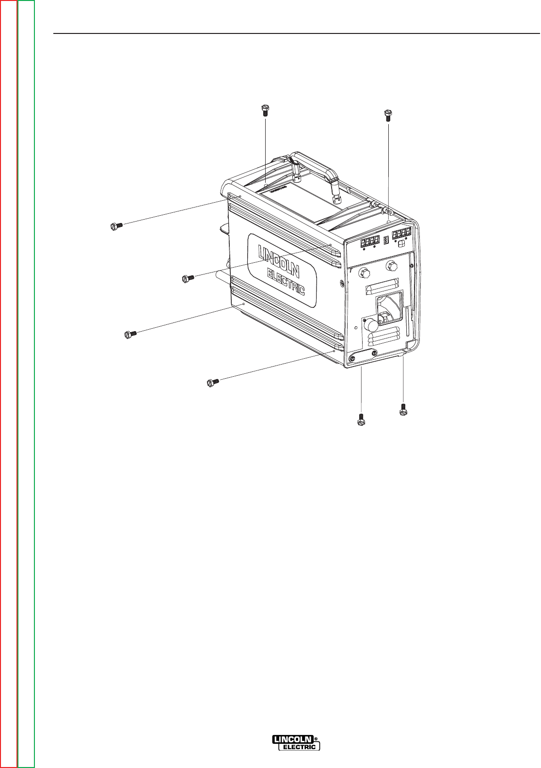
" .+V,+&(/%
,+&(/%)+(.+(CONTINUED)
)+(.+
1. Remove the input power from the LN25 PRO
unit.
2. Using the 1/4-20 nut driver, remove the 8
screws holding the control box. Loosen the
cord grip connector, and slide the control box
assembly out of the case. See <:HE8
-+(.%,!((-"' +)"+
%'S)+(
Return to Section TOC Return to Section TOC Return to Section TOC Return to Section TOC
Return to Master TOC Return to Master TOC Return to Master TOC Return to Master TOC

Service and repair should be performed by only Lincoln Electric factory trained personnel.
Unauthorized repairs performed on this equipment may result in danger to the technician
or machine operator and will invalidate your factory warranty. For your safety and to avoid
electrical shock, please observe all safety notes and precautions detailed throughout this
manual.
If for any reason you do not understand the test procedures or are unable to perform the
test/repairs safely, contact the Lincoln Electric Service Department for electrical trou-
bleshooting assistance before you proceed. Call 1-888-935-3877.
-,-,+")-"('
This test will determine if the gas solenoid circuit is faulty.
&-+"%,'
1/4-20 Nut driver
#10-24 Nut driver
Digital meter
,,(%'("-,-
0+'"'
-+(.%,!((-"' +)"+
%'S)+(
Return to Section TOC Return to Section TOC Return to Section TOC Return to Section TOC
Return to Master TOC Return to Master TOC Return to Master TOC Return to Master TOC
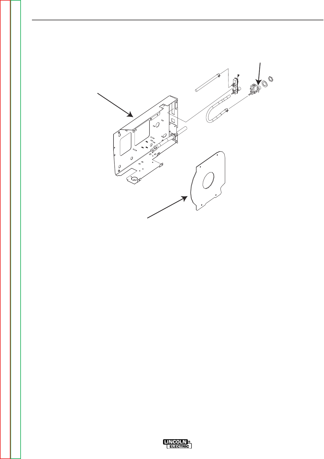
GAS SOLENOID
CONTROL BOX
CONTROL BOX COVER
" .+V ,,(%'("
,,(%'("-,-(CONTINUED)
)+(.+
1. Perform the Case Removal Procedure.
2. Remove the five #10-24 x .50 screws holding
the control box cover and access the solenoid
leads. See <:HE8.
3. Apply the correct input voltage (15-110vdc) to
the unit.
4. While pressing the gas purge button or acti-
vating the gun trigger, check for approximate-
ly 4VDC is present at the solenoid leads. If
the 4VDC is present the solenoid should acti-
vate. If the 8VDC is present but the solenoid
does not activate the solenoid may be faulty.
5. If the 4VDC is missing or low, check the leads
and connections between the solenoid and
the control board. See the Wiring Diagram.
If the leads and connections are ok, the con-
trol board may be faulty.
6. If high voltage is seen (Approx. 35 volts) the
solenoid coil is open.
7. Normal solenoid coil resistance is 22 ohms.
8. The solenoid can also be checked by discon-
necting the leads and applying 12VDC direct-
ly to the terminals. If the solenoid does not
activate the solenoid is faulty.
9. If the solenoid fails any of the above tests
replace it.
10. Reassemble the feeder in reverse order.
-+(.%,!((-"' +)"+
%'S)+(
Return to Section TOC Return to Section TOC Return to Section TOC Return to Section TOC
Return to Master TOC Return to Master TOC Return to Master TOC Return to Master TOC

Service and repair should be performed by only Lincoln Electric factory trained personnel.
Unauthorized repairs performed on this equipment may result in danger to the technician
or machine operator and will invalidate your factory warranty. For your safety and to avoid
electrical shock, please observe all safety notes and precautions detailed throughout this
manual.
If for any reason you do not understand the test procedures or are unable to perform the
test/repairs safely, contact the Lincoln Electric Service Department for electrical trou-
bleshooting assistance before you proceed. Call 1-888-935-3877.
-,-,+")-"('
This test will determine if the contactor is faulty.
&-+"%,'
1/4-20 Nut driver
#10-24 Nut driver
Digital meter
('--(+-,-
0+'"'
-+(.%,!((-"' +)"+
%'S)+(
Return to Section TOC Return to Section TOC Return to Section TOC Return to Section TOC
Return to Master TOC Return to Master TOC Return to Master TOC Return to Master TOC
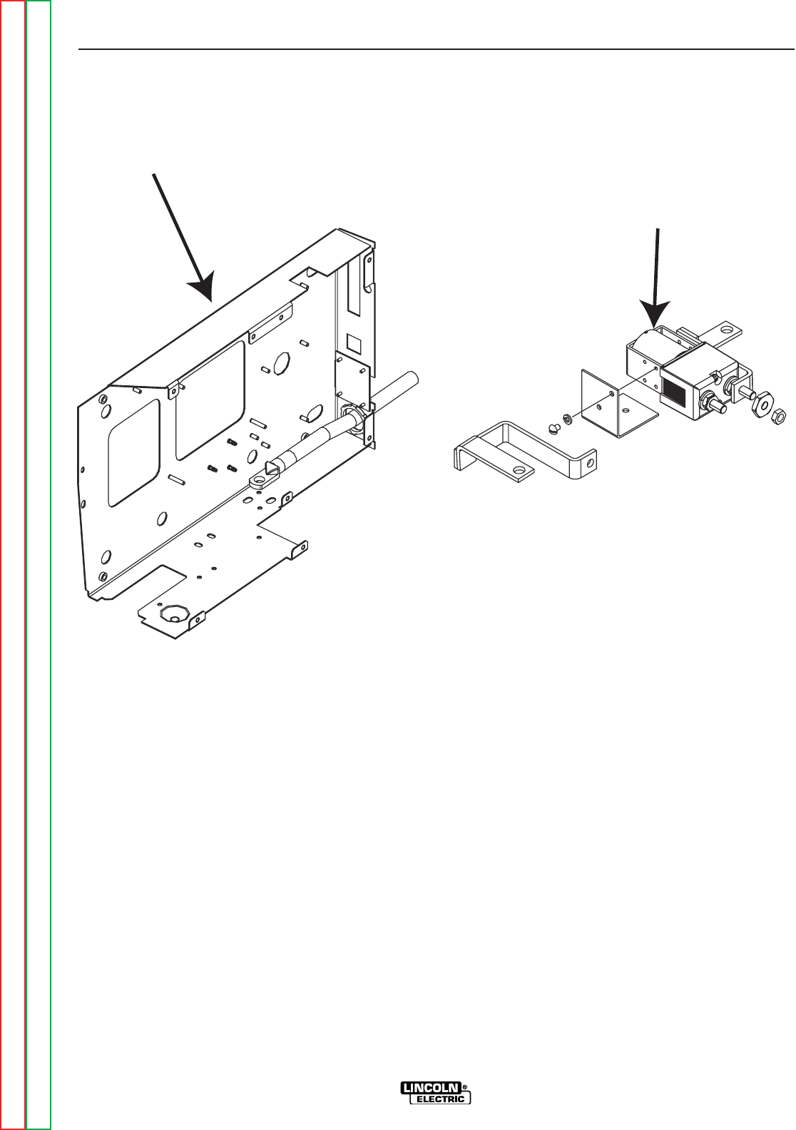
CONTACTOR
CONTROL BOX
" .+V('--(+
('--(+-,-(CONTINUED)
)+(.+
1. Perform the Case Removal Procedure.
2. Remove the 5 #10-24 x .50 screws holding
the control box cover to access the contactor
leads. See Figure F.2.
3. Apply the correct input voltage (15-110vdc) to
the LN25 PRO unit.
4. Check for the correct voltage at leads 507 and
578 at the contactor. Look for 0VDC when the
trigger is open and about 3VDC when it is
closed. See wiring diagram.
5. If the 3VDC is missing or low, check the leads
and connections between the Contactor and
the control board. See the Wiring Diagram.
If the leads and connections are ok, the con-
trol board may be faulty.
6. If high voltage is seen (Approx. 35 volts) the
Contactor coil is open.
7. Normal solenoid coil resistance is 4 ohms.
8. The Contactor can also be checked by dis-
connecting the leads and applying 12VDC
directly to the terminals. If the solenoid does
not activate the solenoid is faulty.
9. If the contactor does not pass all the above
tests it needs to be replaced. See contactor
removal and replacement procedures.
10. Reassemble the feeder in reverse order.
-+(.%,!((-"' +)"+
%'S)+(
Return to Section TOC Return to Section TOC Return to Section TOC Return to Section TOC
Return to Master TOC Return to Master TOC Return to Master TOC Return to Master TOC

Service and repair should be performed by only Lincoln Electric factory trained personnel.
Unauthorized repairs performed on this equipment may result in danger to the technician
or machine operator and will invalidate your factory warranty. For your safety and to avoid
electrical shock, please observe all safety notes and precautions detailed throughout this
manual.
If for any reason you do not understand the test procedures or are unable to perform the
test/repairs safely, contact the Lincoln Electric Service Department for electrical trou-
bleshooting assistance before you proceed. Call 1-888-935-3877.
-,-,+")-"('
This test will help determine if the motor and tach circuit is faulty.
&-+"%,'
1/4-20 nut driver
#10-24 nut driver
Digital meter
+"/&(-(+'-!$-,-
0+'"'
-+(.%,!((-"' +)"+
%'S)+(
Return to Section TOC Return to Section TOC Return to Section TOC Return to Section TOC
Return to Master TOC Return to Master TOC Return to Master TOC Return to Master TOC

CASE
CONTROL BOX ASSEMBLY
" .+V('-+(%(1,,&%2
+"/&(-(+'-!$-,-(CONTINUED)
)+(.+
1. Perform the Case Removal Procedure.
2. Remove the 5 #10-24 x .50 screws holding
the control box cover to access the contactor
leads. See Figure F.2.
3. Remove the 5 #10-24 screws holding the con-
trol box cover, and locate the two motor leads
and the 3 tach leads See the Wiring
Diagram.
4. Apply the correct input voltage (15-110vdc) to
the unit.
5. With trigger activated and the motor running
check for 2.6VDC min. to 32VDC max.
between the black and white motor leads
(pins 7 and 8).
'(-If the tach feedback is missing the board
will limit the motor voltage to 10VDC no
matter where the w/s pot is set.
6. Check for 1.5 ohms of resistance between the
black and white leads. Also make sure there
is at least 550k ohms of resistance between
both leads and the motor shell.
7. With the trigger activated and the motor run-
ning check for 15.6VDC input on the black
and red tach leads. Check for 6.2vdc at any
speed or ≈72hz (min.). to ≈1.2Khz (max). on
the black and blue return leads.
8. For further testing on the drive motor you can
use an isolated source and apply between
2.6VDC and 32VDC to the motor leads.
9. If all the above voltages are not there the
motor or tach needs to be replaced. See Wire
Drive Motor and Gear Box Removal and
Replacement.
-+(.%,!((-"' +)"+
%'S)+(
Return to Section TOC Return to Section TOC Return to Section TOC Return to Section TOC
Return to Master TOC Return to Master TOC Return to Master TOC Return to Master TOC

Service and repair should be performed by only Lincoln Electric factory trained personnel.
Unauthorized repairs performed on this equipment may result in danger to the technician
or machine operator and will invalidate your factory warranty. For your safety and to avoid
electrical shock, please observe all safety notes and precautions detailed throughout this
manual.
If for any reason you do not understand the test procedures or are unable to perform the
test/repairs safely, contact the Lincoln Electric Service Department for electrical trou-
bleshooting assistance before you proceed. Call 1-888-935-3877.
-,-,+")-"('
This test will determine if the motor overload circuit is faulty.
&-+"%,'
1/4-20 nut driver
#10-24 nut driver
Digital meter
&(-(+(/+%(-,-
0+'"'
-+(.%,!((-"' +)"+
%'S)+(
Return to Section TOC Return to Section TOC Return to Section TOC Return to Section TOC
Return to Master TOC Return to Master TOC Return to Master TOC Return to Master TOC
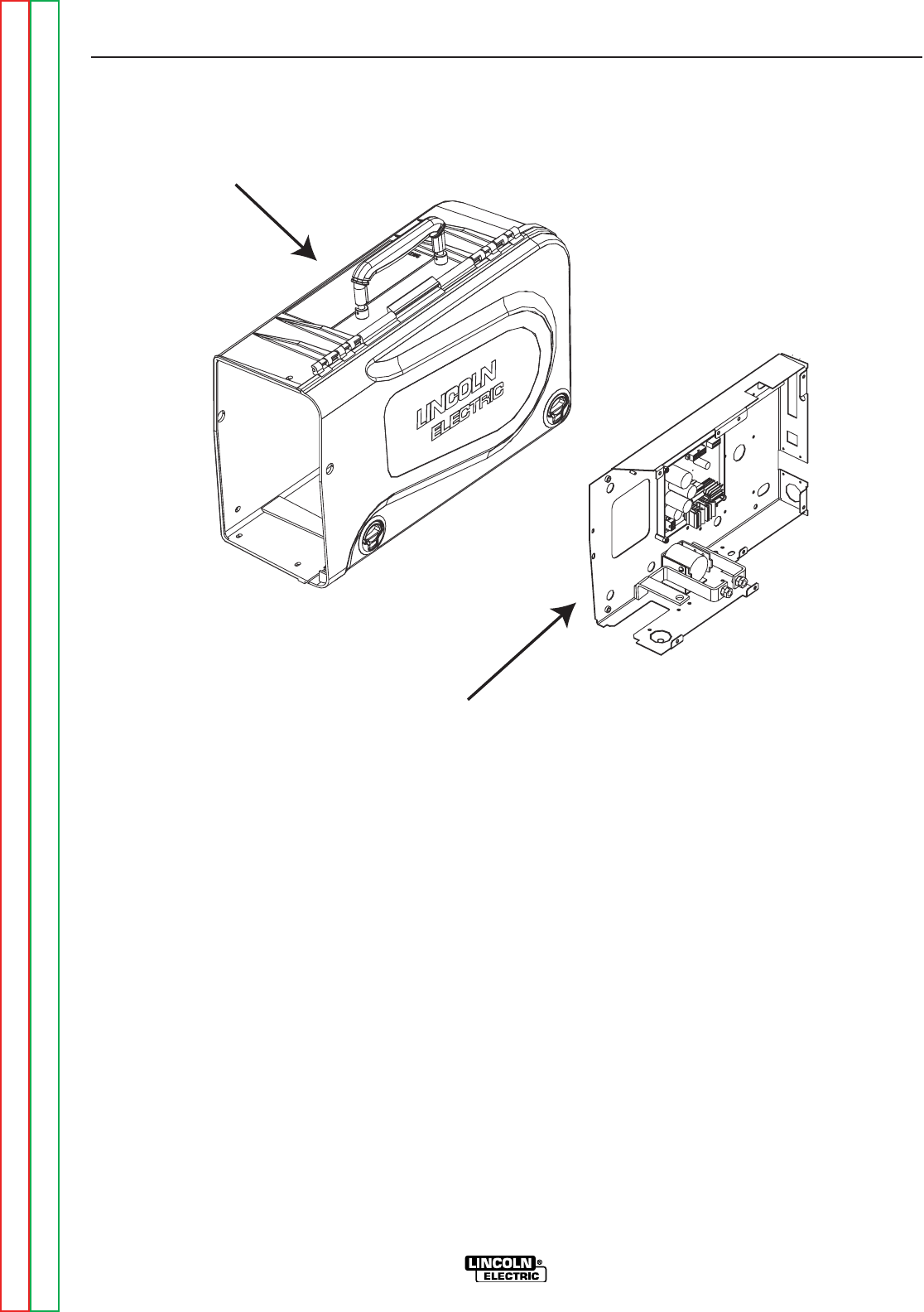
CASE
CONTROL BOX ASSEMBLY
" .+V('-+(%(1,,&%2
&(-(+(/+%(-,-(CONTINUED)
)+(.+
1. Perform the Case Removal Procedure.
2. Remove the 5 #10-24 x .50 screws holding
the control box cover to access the contactor
leads. See Figure F.2.
3. Remove the five #10-24 screws holding the
control box cover, and locate the two motor
leads and 3 tach leads. See the Wiring
Diagram.
4. Apply the correct input voltage (15-110vdc) to
the unit.
5. With the trigger activated and the motor run-
ning check the motor armature current.
Normal armature current is less then 3 amps.
6. If the amperage exceeds 3.2 amps for more
than 8 seconds the motor will be disabled.
7. If the motor armature current is normal and
the motor still shuts down the control board
may be faulty.
8. If the current is high check for restrictions in
the feed system. They can be caused by a
clogged liner, spindle tightness, drive rolls to
tight, fault drive motor or a faulty gearbox.
9. After testing replace faulty parts and reassem-
ble the feeder in reverse order of disassembly.
-+(.%,!((-"' +)"+
%'S)+(
Return to Section TOC Return to Section TOC Return to Section TOC Return to Section TOC
Return to Master TOC Return to Master TOC Return to Master TOC Return to Master TOC

Service and repair should be performed by only Lincoln Electric factory trained personnel.
Unauthorized repairs performed on this equipment may result in danger to the technician
or machine operator and will invalidate your factory warranty. For your safety and to avoid
electrical shock, please observe all safety notes and precautions detailed throughout this
manual.
If for any reason you do not understand the test procedures or are unable to perform the
test/repairs safely, contact the Lincoln Electric Service Department for electrical trou-
bleshooting assistance before you proceed. Call 1-888-935-3877.
-,-,+")-"('
This procedure will aid the technician in the removal and replacement of the contactor.
&-+"%,'
1/4-20 nut driver
#10-24 nut driver
Adjustable wrench
Torque wrench
('--(++&(/%'+)%&'-)+(.+
0+'"'
-+(.%,!((-"' +)"+
%'S)+(
Return to Section TOC Return to Section TOC Return to Section TOC Return to Section TOC
Return to Master TOC Return to Master TOC Return to Master TOC Return to Master TOC
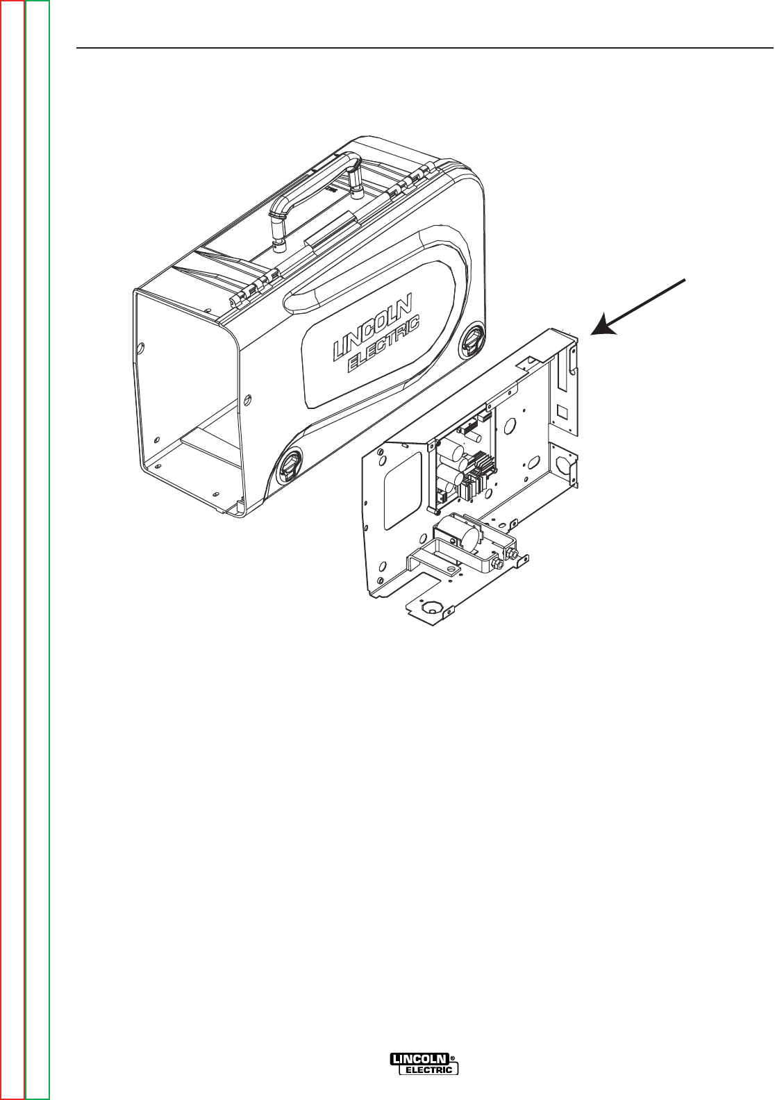
CONTROL BOX
" .+V('-+(%(1
('--(++&(/%'+)%&'-)+(.+(CONTINUED)
+&(/%)+(.+
1. Perform the Case Removal Procedure.
2. Remove the 5 #10-24 x .50 screws holding
the control box cover to access the contactor
leads. See Figure F.2.
3. Disconnect both of the buss bar connectors.
DO NOT loosen the mounting block before
loosening the buss bar. See <:HE8.
4. Remove the five #10-24 x .50 screws from the
wire drive panel, and separate the panel from
the control box.
5. Remove the two #10-24 x .50 screws at the
base of the control box that holds the contac-
tor and remove the contactor.
6. Disconnect the coil leads, and the buss bars
from the contactor.
-+(.%,!((-"' +)"+
%'S)+(
Return to Section TOC Return to Section TOC Return to Section TOC Return to Section TOC
Return to Master TOC Return to Master TOC Return to Master TOC Return to Master TOC
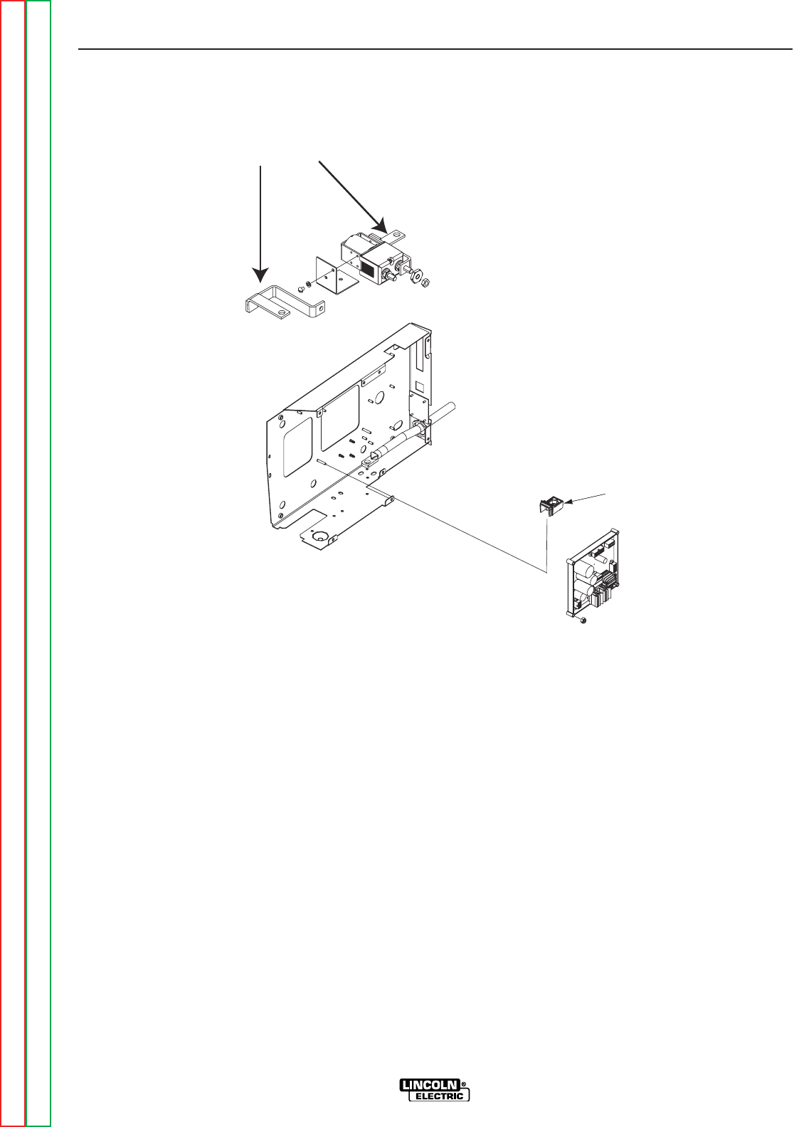
MOUNTING BLOCK
BUSS BAR
" .+V.,,+'&(.'-"' %($
('--(++&(/%'+)%&'-)+(.+(CONTINUED)
+)%&'-)+(.+
1. Loosely connect the buss bars to the new
contactor.
2. Reconnect the coil leads. Slide the buss bar
into the mounting block and start the 1/2-13
bolt.
3. Using the two #10-24 x .50 screws reattach
the contactor to the control box.
4. Tighten the buss bars to the contactor to 15fp.
5. Slide the wire drive panel into place and reat-
tach using the five screws.
6. Reconnect the gas hose and tighten the other
two buss bar connections.
7. Slide the control box into the case and
reassemble in reverse order.
-+(.%,!((-"' +)"+
%'S)+(
Return to Section TOC Return to Section TOC Return to Section TOC Return to Section TOC
Return to Master TOC Return to Master TOC Return to Master TOC Return to Master TOC


Service and repair should be performed by only Lincoln Electric factory trained personnel.
Unauthorized repairs performed on this equipment may result in danger to the technician
or machine operator and will invalidate your factory warranty. For your safety and to avoid
electrical shock, please observe all safety notes and precautions detailed throughout this
manual.
If for any reason you do not understand the test procedures or are unable to perform the
test/repairs safely, contact the Lincoln Electric Service Department for electrical trou-
bleshooting assistance before you proceed. Call 1-888-935-3877.
-,-,+")-"('
This procedure will aid the technician in the removal and replacement of the front panel.
&-+"%,'
1/4-20 Nut driver
+('-)'%+&(/%'+)%&'-)+(.+
0+'"'
-+(.%,!((-"' +)"+
%'S)+(
Return to Section TOC Return to Section TOC Return to Section TOC Return to Section TOC
Return to Master TOC Return to Master TOC Return to Master TOC Return to Master TOC
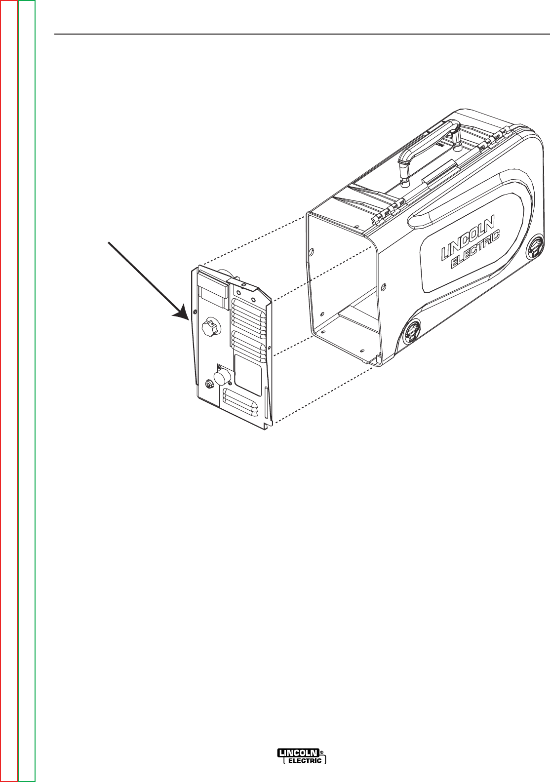
FRONT PANEL
" .+V+('-)'%
+('-)'%+&(/%'+)%&'-)+(.+(CONTINUED)
+&(/%)+(.+
1. Perform the Case Removal Procedure.
2. Remove the 5 #10-24 x .50 screws holding
the control box cover to access the contactor
leads. See Figure F.2.
3. Remove the two 1/4-20 screws that hold the
front panel and lift it out. See <:HE8
4. Disconnect the molex plugs from the control
harness. See wiring diagram.
5. Disconnect the work lead and set it aside to
use with the new panel.
+)%&'-)+(.+
1. Connect the work lead that was previously
removed.
2. Reconnect the molex plugs.
3. Slide the front panel into the control box and
attach it with two 1/4-20 screws.
4. Slide the control box into the case and attach
it with the remaining 1/4-20 screws.
-+(.%,!((-"' +)"+
%'S)+(
Return to Section TOC Return to Section TOC Return to Section TOC Return to Section TOC
Return to Master TOC Return to Master TOC Return to Master TOC Return to Master TOC

Service and repair should be performed by only Lincoln Electric factory trained personnel.
Unauthorized repairs performed on this equipment may result in danger to the technician
or machine operator and will invalidate your factory warranty. For your safety and to avoid
electrical shock, please observe all safety notes and precautions detailed throughout this
manual.
If for any reason you do not understand the test procedures or are unable to perform the
test/repairs safely, contact the Lincoln Electric Service Department for electrical trou-
bleshooting assistance before you proceed. Call 1-888-935-3877.
-,-,+")-"('
The procedure will aid the technician in the removal and replacement of the wire drive
motor and gear box.
&-+"%,'
1/4-20 Nut driver
#10-24 Nut driver
3/8 nut driver
Phillips head screwdriver
0"++"/&(-(+' +(1
+&(/%'+)%&'-)+(.+
0+'"'
-+(.%,!((-"' +)"+
%'S)+(
Return to Section TOC Return to Section TOC Return to Section TOC Return to Section TOC
Return to Master TOC Return to Master TOC Return to Master TOC Return to Master TOC
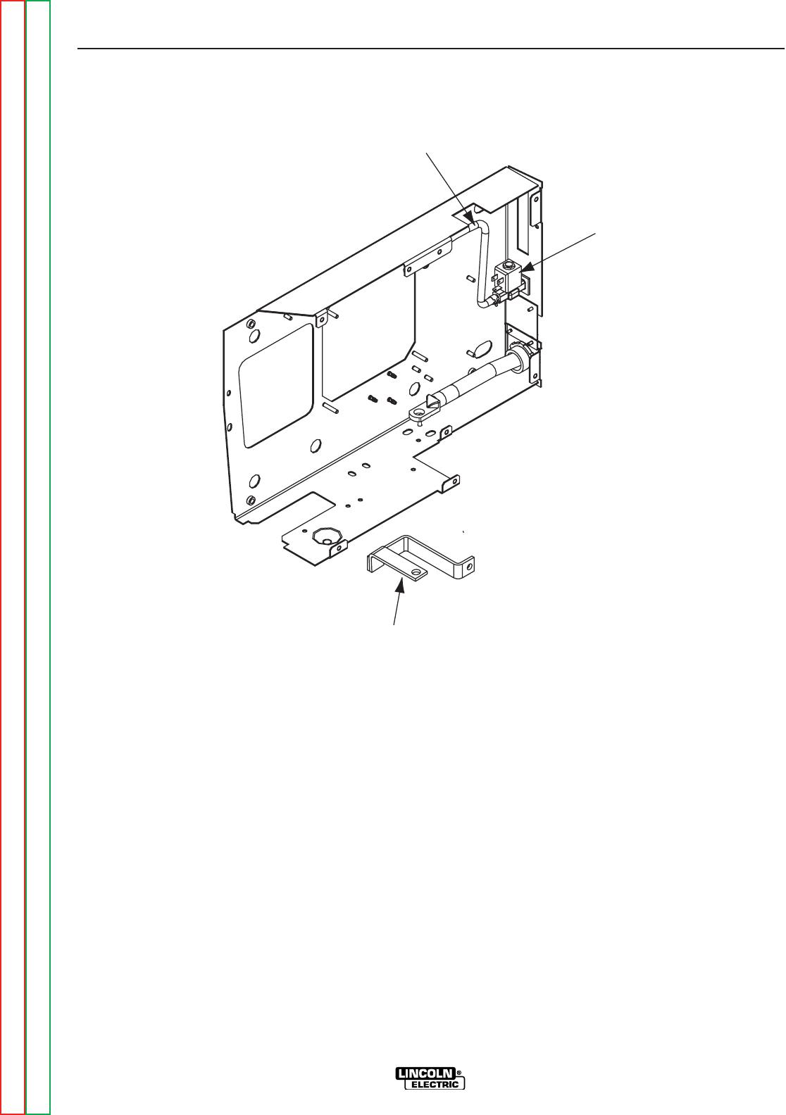
Gas SolenoidGas Solenoid
Gas HoseGas Hose
Buss BarBuss Bar
" .+V.,,+' ,!(,+&(/%
0"++"/&(-(+' +(1
+&(/%'+)%&'-)+(.+(CONTINUED)
+&(/%)+(.+
1. Perform the Case Removal Procedure.
2. Remove the 5 #10-24 x .50 screws holding
the control box cover to access the contactor
leads. See Figure F.2.
3. Disconnect the gas hose and the buss bar
from the drive deck. See <:HE8.
4. Remove the four #10-24 x .50 screws holding
the control box cover.
5. Remove the five #10-24 x .50 screws from the
wire drive panel, and separate the panel from
the control box. See Figure F.10.
6. Remove the plastic drive gear cover and with
a phillips head screwdriver remove the drive
gear. See Figure F.10.
7. Remove the tach and motor leads by discon-
necting the P9 connector. see wiring diagram.
8. Remove the three M6 x 1.00 phillips pan head
screws holding the motor to the motor panel
and lift out the motor.
9. Remove the four 1/4-20 x .50 screws from the
back of the motor panel and remove the drive
deck. Note screw locations for reassembly.
-+(.%,!((-"' +)"+
%'S)+(
Return to Section TOC Return to Section TOC Return to Section TOC Return to Section TOC
Return to Master TOC Return to Master TOC Return to Master TOC Return to Master TOC
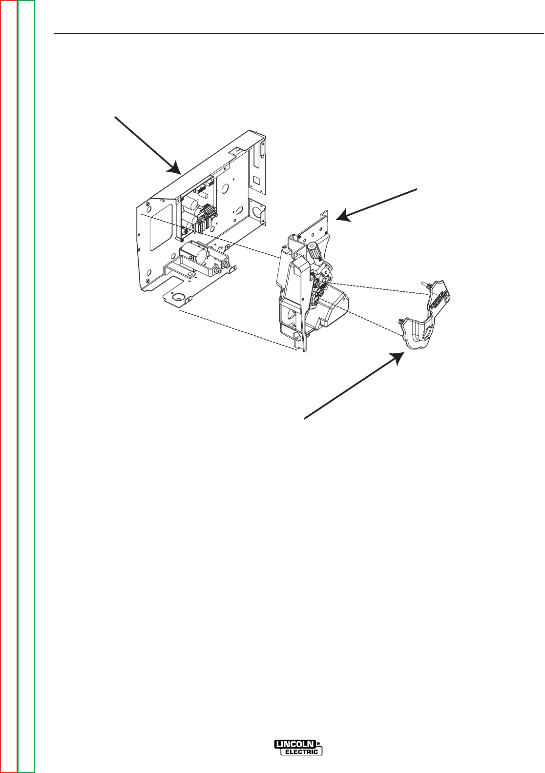
CONTROL BOX
WIRE DRIVE PANEL
DRIVE GEAR COVER
" .+V0"++"/)'%+&(/%
0"++"/&(-(+' +(1
+&(/%'+)%&'-)+(.+(CONTINUED)
+)%&'-)+(.+
1. Line up the gear box with the four holes on the
panel. Replace and tighten the four 1/4-20 x
.50 screws.
2. Insert the drive motor through the panel and
gear box. Line up and tighten the three M6 x
1.00 in. phillips pan head screws.
3. Replace the drive gear and secure in place
using the screw and lock washer previously
removed.
4. Replace the drive rolls and secure the locking
rings.
5. Reconnect the motor and tach leads to har-
ness.
6. Reassemble the wire drive panel and the con-
trol box using the five #10-24 x .50 screws.
7. Reconnect the gas hose and the buss bar
assembly.
8. Replace the control box cover using the four
#10-24 x .50 screws.
9. Slide the control box into the case and secure
it in reverse order.
10. Reinstall the gun.
-+(.%,!((-"' +)"+
%'S)+(
Return to Section TOC Return to Section TOC Return to Section TOC Return to Section TOC
Return to Master TOC Return to Master TOC Return to Master TOC Return to Master TOC


Service and repair should be performed by only Lincoln Electric factory trained personnel.
Unauthorized repairs performed on this equipment may result in danger to the technician
or machine operator and will invalidate your factory warranty. For your safety and to avoid
electrical shock, please observe all safety notes and precautions detailed throughout this
manual.
If for any reason you do not understand the test procedures or are unable to perform the
test/repairs safely, contact the Lincoln Electric Service Department for electrical trou-
bleshooting assistance before you proceed. Call 1-888-935-3877.
-,-,+")-"('
The procedure will aid the technician in the removal and replacement of the Control PC
Board.
&-+"%,'
1/4-20 Nut driver
#10-24 Nut driver
3/8 Nut driver
)(++&(/%'+)%&'-)+(.+
0+'"'
-+(.%,!((-"' +)"+
%'S)+(
Return to Section TOC Return to Section TOC Return to Section TOC Return to Section TOC
Return to Master TOC Return to Master TOC Return to Master TOC Return to Master TOC
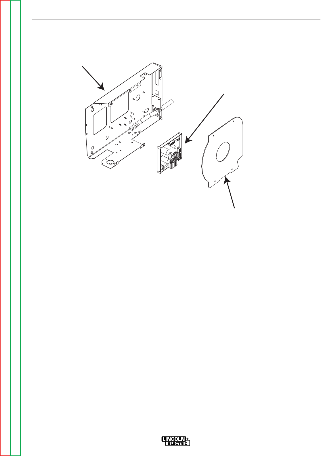
CONTROL BOX COVER
CONTROL BOX
CONTROL BOARD
" .+V('-+(%)(+%(-"('
)Z(++&(/%'+)%&'-)+(.+(CONTINUED)
+&(/%)+(.+
1. Perform the Case Removal Procedure.
2. Remove the 5 #10-24 x .50 screws holding
the control box cover to access the contactor
leads. See Figure F.2.
3. Disconnect the gas hose and the buss bar
from the drive deck.
4. Remove the five #10-24 x .50 screws from the
wire drive panel and separate the panel from
the box to access the control board.
5. Locate the control board and remove the har-
ness plugs on the control board. Observe sta-
tic electricity precautions. Label plugs for
reassembly. See <:HE8.
6. Remove the 4 nuts holding the board using
the 3/8 inch nut driver, and remove the board.
+)%&'-)+(.+
1. Remove the new control board from the static
bag and place it on the 4 studs.
2. Reassemble the 4 nuts and tighten hand tight.
3. Reassemble the harness plugs.
4. Replace the wire drive panel and control box
assembly in reverse order.
5. Reconnect the buss bar and the gas hose.
6. Replace the control box cover.
7. Slide the control box into the case and secure
it in reverse order.
-+(.%,!((-"' +)"+
%'S)+(
Return to Section TOC Return to Section TOC Return to Section TOC Return to Section TOC
Return to Master TOC Return to Master TOC Return to Master TOC Return to Master TOC

Service and repair should be performed by only Lincoln Electric factory trained personnel.
Unauthorized repairs performed on this equipment may result in danger to the technician
or machine operator and will invalidate your factory warranty. For your safety and to avoid
electrical shock, please observe all safety notes and precautions detailed throughout this
manual.
If for any reason you do not understand the test procedures or are unable to perform the
test/repairs safely, contact the Lincoln Electric Service Department for electrical trou-
bleshooting assistance before you proceed. Call 1-888-935-3877.
-,-,+")-"('
The procedure will aid the technician in the removal and replacement of the gas solenoid.
&-+"%,'
#10-24 nut driver
Adjustable pliers
,,(%'("+&(/%'+)%&'-)+(.+
0+'"'
-+(.%,!((-"' +)"+
%'S)+(
Return to Section TOC Return to Section TOC Return to Section TOC Return to Section TOC
Return to Master TOC Return to Master TOC Return to Master TOC Return to Master TOC
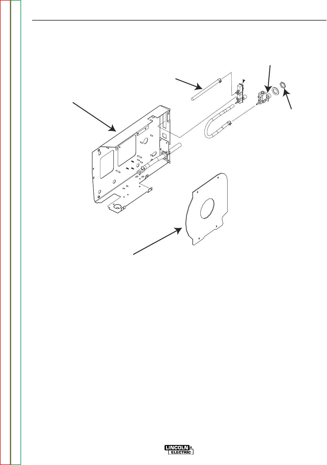
LOCK NUT
GAS SOLENOID
GAS HOSE
CONTROL BOX
CONTROL BOX COVER
" .+V,(%'("'.-'!(,
,,(%'("
+&(/%'+)%&'-)+(.+(CONTINUED)
)+(.+
1. Perform the Case Removal Procedure.
2. Remove the 5 #10-24 x .50 screws holding
the control box cover to access the contactor
leads. See Figure F.2.
3. Remove the 2 wires on the solenoid coil. See
wiring diagram.
4. Using the pliers remove the gas hose. Be
careful not to damage the hose. See <:HE8
.
5. Remove the lock nut holding the solenoid.
See <:HE8.
6. Remove the solenoid from the unit.
7. Install the new solenoid with the attached
hardware.
8. Reconnect the gas hose.
9. Reconnect the wires to the solenoid coil.
10. Replace the control box cover.
-+(.%,!((-"' +)"+
%'S)+(
Return to Section TOC Return to Section TOC Return to Section TOC Return to Section TOC
Return to Master TOC Return to Master TOC Return to Master TOC Return to Master TOC

-+(.%,!((-"' +)"+
%'S)+(
+-,--++)"+
+8G8FG4@46;<A8
• If it is rejected under test for any reason that requires you to
remove any part which could affect the machine’s electrical charac-
teristics.
(+
• If you repair or replace any electrical components.
,-.)
1. Connect a supply of filtered compressed air at 80 psi to the gas inlet.
2. Supply 15 to 110 VAC to the machine.
3. Connect the gun to the connector block and connect the trigger.
()+-"('/+""-"('
WIRE FEED SPEED (Standard) ...................50 through 700 IPM
WIRE FEED SPEED (Ext. Torque)...................50 through 400 IPM
VOLTMETER (Analog)..............Must read Inpit Voltage +/-2%
VOLTMETER (Digital)...............Must operate at 3 TO 12 VDC input volts
GAS SOLENOID.......................Must operate when Gun Trigger is activated.
CONTACTOR............................Must operate when Gun Trigger is activated
or after Pre-flow time if Timer Kit is installed.
Return to Section TOC Return to Section TOC Return to Section TOC Return to Section TOC
Return to Master TOC Return to Master TOC Return to Master TOC Return to Master TOC


-%(('-'-," +&,-"('
%'S)+(
?86GE<64?<4:E4@F
Wiring Diagram - Code 11387, 11388 (G5681) . . . . . . . . . . . . . . . . . . . . . . . . . . . . . . . . . . . . . . . . . . . . . .G-2
Wiring Diagram - Code 11507, 11508 (G5681-1) . . . . . . . . . . . . . . . . . . . . . . . . . . . . . . . . . . . . . . . . . . . .G-3
Wiring Diagram - Code 11620, 11621,11716,11717 (G5681-2) . . . . . . . . . . . . . . . . . . . . . . . . . . . . . . . . .G-4
Wiring Diagram - Code 11746, 11747 (G5681-3) . . . . . . . . . . . . . . . . . . . . . . . . . . . . . . . . . . . . . . . . . . . .G-5
Schematic - Complete Machine - Code 11387, 11388 (G5683) . . . . . . . . . . . . . . . . . . . . . . . . . . . . .G-6 / G-7
Schematic - Complete Machine - Code 11507, 11508 (G5683-1) . . . . . . . . . . . . . . . . . . . . . . . . . . .G-8 / G-9
Schematic - Complete Machine - Code 11620, 11621,11716, 11717 (G5683-2) . . . . . . . . . . . . . .G-10 / G-11
Schematic - Complete Machine - Code 11746, 11747 (G5683-3) . . . . . . . . . . . . . . . . . . . . . . . . .G-12 / G-13
Schematic - Control PC Board* - Code 11387/8, 11507/8 (G4745-1) . . . . . . . . . . . . . . . . . . . . . .G-14 / G-18
Schematic - Control PC Board* - Code 11620/1, 11716/7, 11746/7 (G4783-1) . . . . . . . . . . . . . . .G-19 / G-23
Schematic - Motor Filter PC Board* - Code 11746, 11747 (S27505-1) . . . . . . . . . . . . . . . . . . . . . . . . . . .G-24
Schematic - K2330-2 Timer Kit PC Board* - All Codes (M21341-1) . . . . . . . . . . . . . . . . . . . . . . . . . . . . .G-25
'(-Many PC Board Assemblies are now totally encapsulated, surface mounted and or multi-layered
and are therefore considered to be unserviceable. Assembly drawings of these boards are no
longer provided.
Return to Master TOC Return to Master TOC Return to Master TOC Return to Master TOC
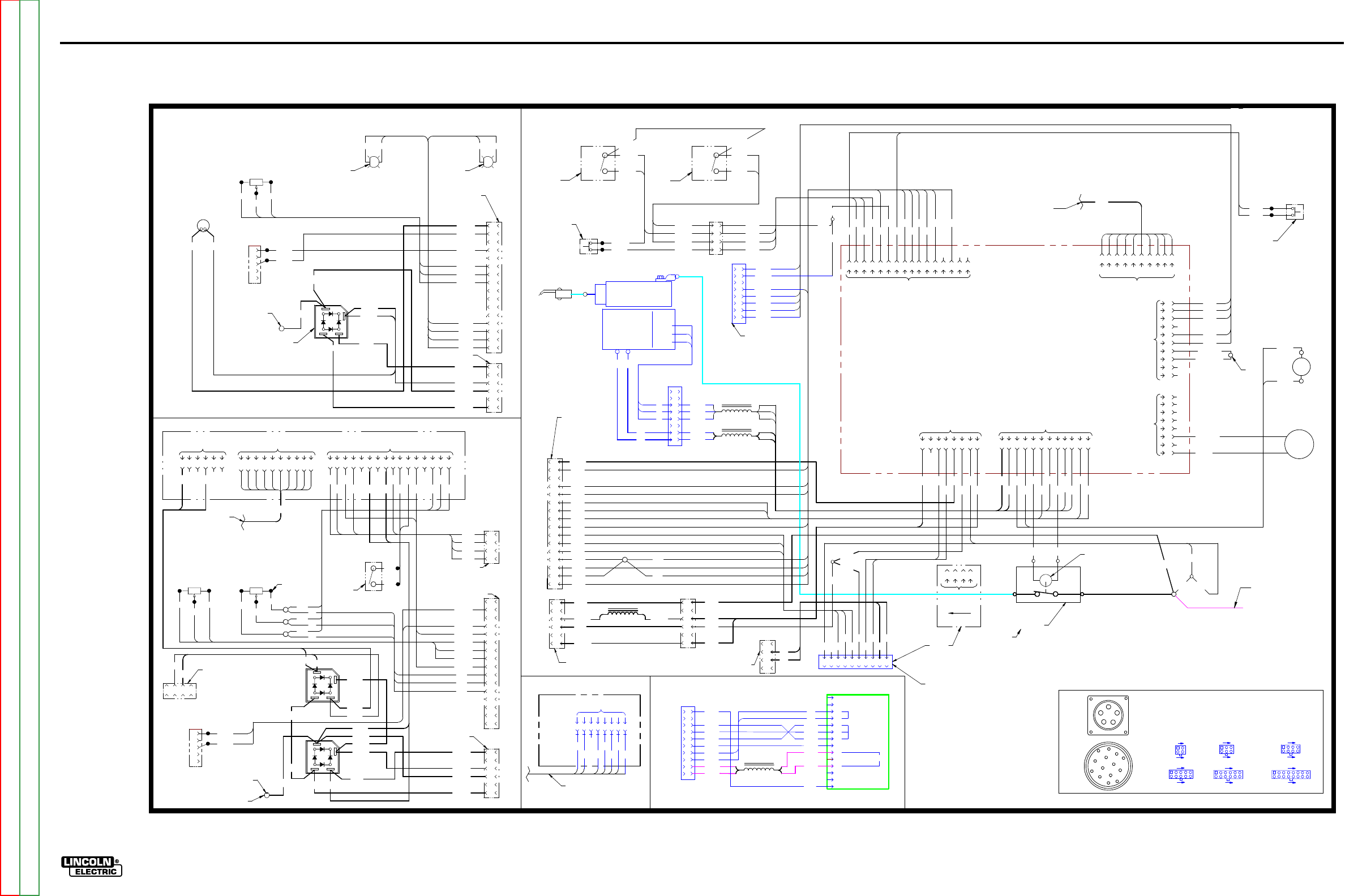
ElECTriCal DiaGrams G-2
lN-25™ prO
WiriNG DiaGram - lN-25 prO - CODEs 11387, 11388 (G5681)
CONTROL P.C
.
BOARD
-
+
BRIDGE
RECTIFIER
AC
AC
POLARITY
LED
A
P14
62
2A
TRIGGER
CONNECTOR
WIRING DIAGRAM LN-25 PRO
G5681
C
J1, J
2, J8, J
15
C
AVI
TY
NU
MBE
RIN
G SEQ
UENCE
(VI
EW
ED FROM COMPONENT
S
IDE OF
P
.C.
BO
ARD
)
6
5
10
1
J6, J
7, J
10
9
8
16
1
4
6
1
3
J3, J
5, J9, J
60
5
4
8
1
J1
2, J
17
FEED
PLATE
P9
8
M
OT
O
R
/
GEARBOX
W
R
TACH
U
B
53
1
B
B
W
69
0
69
1
GAS
SOLENOID
TRIGGER
INTERLOCK
/
2STEP
J3 5
6
3
4
2
1
R
U
B
5
6
3
4
2
1
7
8
J6
123456789
10 11 12 13 14 15 16
50
0A
B
C
D
E
53
7
53
4
55
1
55
0
7
6
5
4
3
2
1
N
OT
E
S:
N.
A. PI
N
NEARES
T T
H
E
FL
A
T
EDG
E
OF
L
E
D
LEN
S
(A
NOD
E)
A
LI
GN
S
W
IT
H
W
HI
TE
LEA
D
OF
L
E
D
SOCKE
T.
N.
B.
T
OG
GL
E
SW
IT
CHE
S
SHOW
N
FR
O
M
REA
R
CONNE
CT
IO
N
SI
D
E
OF
S
W
IT
C
H.
N.C.
PRESE
NT
O
N
CO
NT
R
OL
C
ABL
E
MODEL
S
ONL
Y.
N.D.
PRESE
NT
O
N
ACROS
S
TH
E
AR
C
MODEL
S
ONL
Y.
N.
E.
CONNE
CT
"
EX
TR
A
" T
O
"T
ORQUE
"
O
N
EX
TR
A
TO
RQU
E
MODEL
S
ONL
Y.
N.
F.
N
OT
P
RESE
NT
O
N
A
LL
MODEL
S.
S4
1
GAS PURGE
PUSHBUTTON
SWITCH
S1
S3
COLD
FEED
2
3
4
53
0A
53
0
52
3
58
7
58
7A
P16
1
2
3
4
P7
5
6
72
1A
50
0
62
2A
57
5A
50
0A
62
2
57
5
7
8
57
6A
57
6
N.B.
N.B.
,
N.
F.
N.B.
L5
L4
YELLOW
THERMAL
LED
1W
N.A.
CC
/
CV
S2
52
3A
N.B.
VM
+
66
7B
72
1
ARC
VOLTMETER
1234
J5 J4
1234567
8
9
10 11 12
9
10
J2
A
B
C
DE
J14
57
6A
57
5A
57
7A
10
K2W
R1
WIRE FEED SPEED
CONTROL RHEOSTAT
1B
9
10
11
12
13
14
15
16
62
1A
72
1
1B
1W
2B
2W
57
7
1B
1W
2B
2W
57
7A
66
7B
21
B
67
B
50
0
62
2
50
9C
50
9E
50
9
50
9E
61
0
70
7
53
0
69
0
57
5
57
8
53
1
60
1
57
6
53
7
61
2
58
7
60
6
60
7
60
5
60
8
50
7
57
7
69
1
53
4
1W
2W 3B
4B
P60
61
2
52
3
50
9A
50
9D
50
9D
53
0A
52
3A
58
7A
50
9C
57
6A
57
5A
57
7A
10
K2W
R1
DIGITAL DISPLAY CASE FRONT
PO
ST-FL
OW BURNBACK
TIMER KIT
(
OPTIONA
L)
J60
8
60
1
50
9B
60
5
60
6
60
7
60
8
765
43
2
1
77
A
10
K2W
R2
REMOTE
CONTROL
VOLTAGE
RHEOSTAT
76
A
75
A
70
7
21
A
66
7A
61
0
77
C
76
C
75
C
OUTP
UT
CO
NT
RO
L
A
J19
B
C
D
E
F
G
H
I
J
K
L
M
N
R
EMOTE
VOLTAGE
CO
NT
RO
L
42VA
C
123456789
10
J1
ANALOG DISPLAY CASE FRONT
1
2
3
4
J7
5
6
7
8
9
10
11
12
13
14
15
16
CO
NNE
CTS TO
J7 ON
HARN
ESS
TO P60
ON
HARN
ESS
G
ENER
A
L
INFOR
MAT
ION
EL
EC
T
RIC
A
L
SYMBOLS P
ER
E1537
LE
AD
CO
L
OR COD
ING
B
- B
L
AC
K
W
-
W
HI
TE
50
7
57
8CO
NT
A
CT
O
R
C
OIL
+
1234
J11
CURRENT
TRANSDUCER
CO
NTA
CTO
R
N.C.
N.D.
67
C
50
9B
50
9A
50
9
N.D.
14 PIN CIRCULAR CONNECTOR
TO POWER SOURCE
8
7
6
5
4
3
2
1
60
1
50
9B
60
5
60
6
60
7
60
8
P15
8
7
6
5
4
3
2
1
75
D
10
9
76
D
77
D
41
A
42
A
2
77
D
4
76
D
75
D
42
A
41
A
CO
NNE
CTS TO
P7 ON
C
ASE
F
RO
NT
55
0
55
1
J15 123456789
10
75
C
76
C
77
C
41
42
J1
1, J
1
6, J
18
3
4
1
2
J4
7
6
12
1
J12
A
B
C
D
EF
M
L
K
J
I
N
G
H
67
1
2
67
B
P17
CO
NNE
CTS TO J17
ON
HARN
ESS
CO
NNE
CTS TO 14 PIN
CI
RCU
LA
RCO
NNE
CTO
R
J18
3
4
1
2
3
4
CO
NNE
CTS TO P17
ON
C
ASE FRO
NT
41
42
1234
N.C.
CO
NNE
CTS TO J8
ON P
R
ESET P
.C. BD.
FL
EX
EX
TR
A
TO
RQUE
N.
E.
7
8
5678
67
E
21
E
2A
4A
CO
NNE
CTS
TO T
IMER
KIT
1
2
3
4
5
6
J17
70
8
66
7
4A
2A
72
1A
67F
21
D
62
1
5
6
70
8
67
G
66
7C
62
1C
67
21F
2
4
21F
21
G
67
E
67F
67
D
CO
NNE
CTS TO P18
ON
C
ASE FRO
NT
66
7A
21
A
62
1A
21
E
21
D
21
C
WIRE FEED
SPEED
CONTROL
RHEOSTAT
TO
WORK
C
LIP
2W
N.A.
2B
1
2
67
B
P17
CO
NNE
CTS TO J17
ON
HARN
ESS
3
4
5
6
66
7A
21
A
62
1A
1
2
3
4
5
6
50
0A
62
2A
57
5A
7
8
57
6A
9
10
11
12
13
14
15
16
57
7A
77
76
75
70
7A
-
+
BRIDGE
RECTIFIER
AC
AC
62
1A
21
B
67
B
21
A
TO
WORK
C
LIP
-
+
BRIDGE
RECTIFIER
AC
AC
A
P14
62
2A
TRIGGER
CONNECTOR
50
0A
B
C
D
E
66
7B
J10
1234567 9
10 11 12
70
7A
70
2
21
80
5
70
8
67
80
4
70
1
80
2
8
13 14 15 16
80
1
76
B
77
B
75
B
12 3 4 5 6 7 9
10
8
J8
12 3 4 5 6
J12
41
B
42
B
PRESET P.C
.
BOARD
FL
EX
66
7B
62
1B
P7
1
2
3
4
P11
66
7A
41
B
70
8
P18
CO
NNE
CT TO J18
ON
HARN
ESS
80
5
80
4
80
1
80
2
42
C
41
C
75
75
B
76
76
B
77
77
B
CO
NNE
CTS TO J1
ON
CO
NT
RO
L BD
CO
NNE
CTS TO J7
ON
HARN
ESS
CO
NNE
CTS TO J11
ON
HARN
ESS
67
21
62
1B
42
B
S5
RUN-
IN
N.B.
,
N.C.
41
C
42
C
N.B
.
70
1
70
2
L6
BLACK
RED
FAN
+
-
4B
3B
4B
N.
O.
N.
O.
SHOWN
I
NCV
SHOWN
I
N2STEP
SHOWN OFF
D2
D1
D1
INPUT ELECTRODE
CABLE CONNECTION
1
2
3
4
5
6
67
C
66
7
62
1
21
C
66
7D
L7
G-2
NOTE: This diagram is for reference only. It may not be accurate for all machines covered by this manual. The wiring diagram specific to your code is pasted inside one of the enclosure panels of your machine.
Return to Section TOC Return to Section TOC Return to Section TOC Return to Section TOC
Return to Master TOC Return to Master TOC Return to Master TOC Return to Master TOC
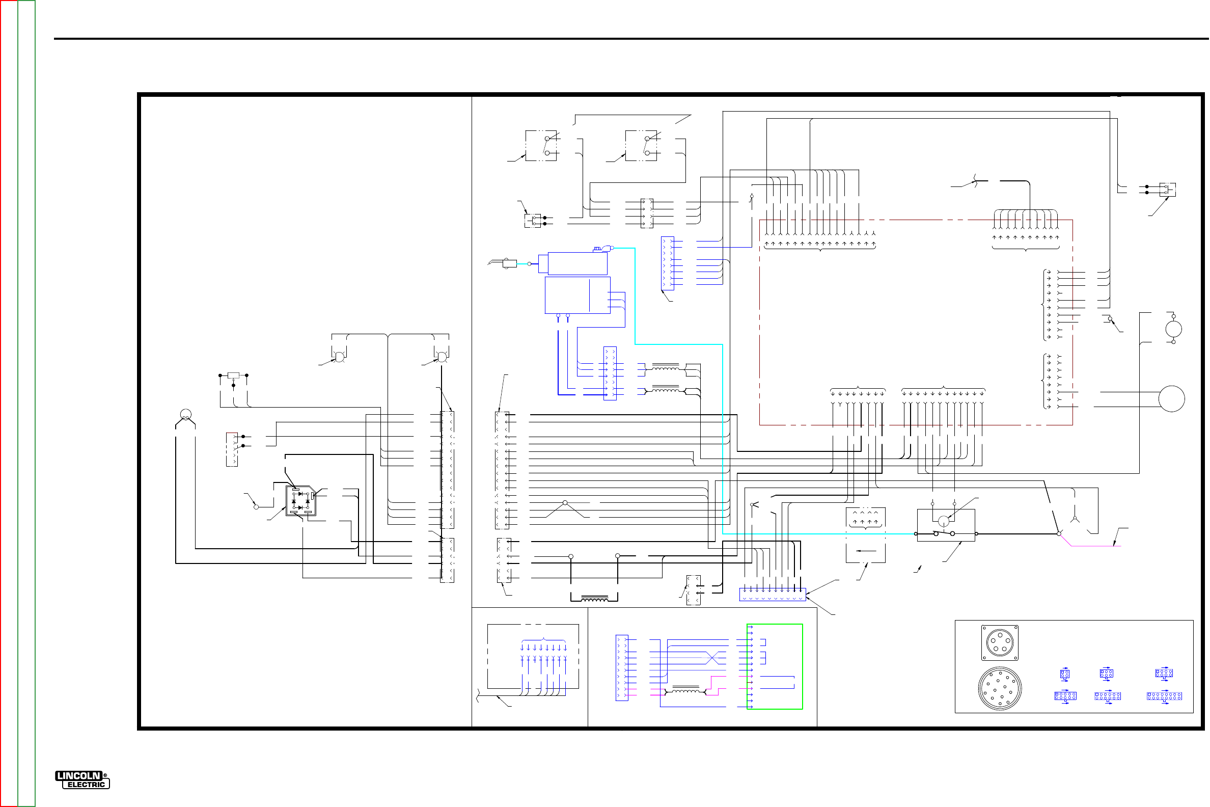
ElECTriCal DiaGrams G-3
lN-25™ prO
WiriNG DiaGram - lN-25 prO - CODEs 11507, 11508 (G5681-1)
CONTROL P.C
.
BOARD
-
+
BRIDGE
RECTIFIER
AC
AC
POLARITY
LED
A
P14
62
2A
TRIGGER
CONNECTOR
WIRING DIAGRAM LN-25 PRO
B
G5681-1
J1, J
2, J8, J
15
C
AVI
TY
NU
MBE
RIN
G SEQ
UENCE
(VI
EW
ED FROM COMPONENT
S
IDE OF
P
.C.
BO
ARD
)
6
5
10
1
J6, J
7, J
10
9
8
16
1
4
6
1
3
J3, J
5, J9, J
60
5
4
8
1
J1
2, J
17
FEED
PLATE
P9
8
M
OT
O
R
/
GEARBOX
W
R
TACH
U
B
53
1
B
B
W
69
0
69
1
GAS
SOLENOID
TRIGGER
INTERLOCK
/
2STEP
J3 5
6
3
4
2
1
R
U
B
5
6
3
4
2
1
7
8
J6
1 2 3456789
10111213141516
50
0A
B
C
D
E
53
7
53
4
55
1
55
0
7
6
5
4
3
2
1
N
OT
E
S:
N.
A. PI
N
NEARES
T T
H
E
FL
A
T
EDG
E
OF
L
E
D
LEN
S
(A
NOD
E)
A
LI
GN
S
W
IT
H
W
HI
TE
LEA
D
OF
L
E
D
SOCKE
T.
N.
B.
T
OG
GL
E
SW
IT
CHE
S
SHOW
N
FR
O
M
REA
R
CONNE
CT
IO
N
SI
D
E
OF
S
W
IT
C
H.
N.C.
PRESE
NT
O
N
CO
NT
R
OL
C
ABL
E
MODEL
S
ONL
Y.
N.D.
PRESE
NT
O
N
ACROS
S
TH
E
AR
C
MODEL
S
ONL
Y.
N.
E.
CONNE
CT
"
EX
TR
A
" T
O
"T
ORQUE
"
O
N
EX
TR
A
TO
RQU
E
MODEL
S
ONL
Y.
N.
F.
N
OT
P
RESE
NT
O
N
A
LL
MODEL
S.
S4
1
GAS PURGE
PUSHBUTTON
SWITCH
S1
S3
COLD
FEED
2
3
4
53
0A
53
0
52
3
58
7
58
7A
P16
1
2
3
4
P7
5
6
72
1A
50
0
62
2A
57
5A
50
0A
62
2
57
5
7
8
57
6A
57
6
N.B.
N.B.
,
N.
F.
N.B.
L5
L4
YELLOW
THERMAL
LED
1W
N.A.
CC
/
CV
S2
52
3A
N.B.
VM
+
66
7B
72
1
ARC
VOLTMETER 1234
J5 J4
1234567
8
9
10 11 12
9
10
J2
A
B
C
DE
J14
57
6A
57
5A
57
7A
10
K2W
R1
WIRE FEED SPEED
CONTROL RHEOSTAT
1B
9
10
11
12
13
14
15
16
62
1A
72
1
1B
1W
2B
2W
57
7
1B
1W
2B
2W
57
7A
66
7B
21
B
67
B
50
0
62
2
50
9C
50
9E
50
9
50
9E
61
0
70
7
53
0
69
0
57
5
57
8
53
1
60
1
57
6
53
7
61
2
58
7
60
6
60
7
60
5
60
8
50
7
57
7
69
1
53
4
1W
2W 3B
4B
P60
61
2
52
3
50
9A
50
9D
50
9D
53
0A
52
3A
58
7A
50
9C
PO
ST-FL
OW BURNBACK
TIMER KIT
(
OPTIONA
L)
J60
8
60
1
50
9B
60
5
60
6
60
7
60
8
765
43
2
1
70
7
21
A
66
7A
61
0
77
C
76
C
75
C
OUTP
UT
CO
NT
RO
L
A
J19
B
C
D
E
F
G
H
I
J
K
L
M
N
R
EMOTE
VOLTAGE
CO
NT
RO
L
42VA
C
1 2 3456789
10
J1
ANALOG DISPLAY CASE FRONT
1
2
3
4
J7
5
6
7
8
9
10
11
12
13
14
15
16
CO
NNE
CTS TO
J7 ON
HARN
ESS
TO P60
ON
HARN
ESS
G
ENER
A
L
INFOR
MAT
ION
EL
EC
T
RIC
A
L
SYMBOLS P
ER
E1537
LE
AD
CO
L
OR COD
ING
B
- B
L
AC
K
W
-
W
HI
TE
50
7
57
8CO
NT
A
CT
O
R
C
OIL
+
1234
J11
CURRENT
TRANSDUCER
CO
NTA
CTO
R
N.C.
N.D.
67
C
50
9B
50
9A
50
9
N.D.
14 PIN CIRCULAR CONNECTOR
TO POWER SOURCE
8
7
6
5
4
3
2
1
60
1
50
9B
60
5
60
6
60
7
60
8
P15
8
7
6
5
4
3
2
1
75
D
10
9
76
D
77
D
41
A
42
A
2
77
D
4
76
D
75
D
42
A
41
A
CO
NNE
CTS TO
P7 ON
C
ASE
F
RO
NT
55
0
55
1
J15 123456789
10
75
C
76
C
77
C
41
42
J1
1, J
1
6, J
18
3
4
1
2
J4
7
6
12
1
J12
A
B
C
D
EF
M
L
K
J
I
N
G
H
67
1
2
67
B
P17
CO
NNE
CTS TO J17
ON
HARN
ESS
CO
NNE
CTS TO 14 PIN
CI
RCU
LA
RCO
NNE
CTO
R
J18
3
4
1
2
3
4
CO
NNE
CTS TO P17
ON
C
ASE FRO
NT
41
42
CO
NNE
CTS TO J8
ON P
R
ESET P
.C. BD.
FL
EX
EX
TR
A
TO
RQUE
N.
E.
7
8
5678
67
E
21
E
2A
4A
CO
NNE
CTS
TO T
IMER
KIT
1
2
3
4
5
6
J17
70
8
66
7
4A
2A
72
1A
67F
21
D
62
1
5
6
70
8
67
C
66
7C
62
1
67
21F
2
4
21F
21
C
67
E
67F
67
D
CO
NNE
CTS TO P18
ON
C
ASE FRO
NT
66
7A
21
A
62
1A
21
E
21
D
21
C
TO
WORK
C
LIP
2W
N.A.
2B
L6
BLACK
RED
FAN
+
-
4B
3B
4B
N.
O.
N.
O.
SHOWN
I
NCV
SHOWN
I
N2STEP
D1
INPUT ELECTRODE
CABLE CONNECTION
66
7D L7
66
7E
66
7
G-3
NOTE: This diagram is for reference only. It may not be accurate for all machines covered by this manual. The wiring diagram specific to your code is pasted inside one of the enclosure panels of your machine.
Return to Section TOC Return to Section TOC Return to Section TOC Return to Section TOC
Return to Master TOC Return to Master TOC Return to Master TOC Return to Master TOC
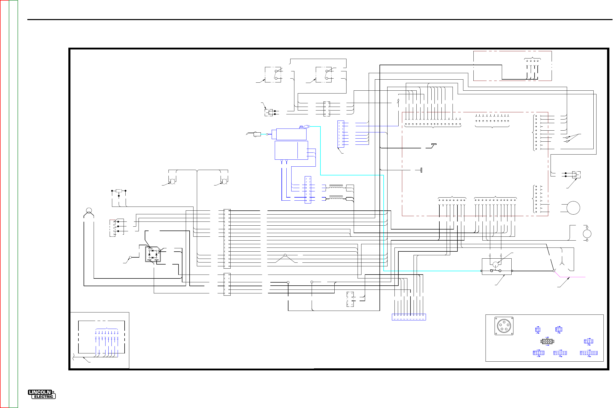
ElECTriCal DiaGrams G-4
lN-25™ prO
WiriNG DiaGram - lN-25 prO - CODEs 11620, 11621, 11716, 11717 (G5681-2)
CONTROL P.C
.
BOARD
WIRING DIAGRAM- LN-25 PRO ANALOG
A
G5681-2
FEED
PLATE
P20/J20
8
M
OT
O
R
/
GEARBOX
W
R
TACH
U
B
53
1
B
B
W
69
0
69
1
GAS
SOLENOID
TRIGGER
INTERLOCK
/
2STEP
J3 5
6
3
4
2
1
R
U
B
5
6
3
4
2
1
7
8
J6
123456789
10 11 12 13 14 15 16
53
7
53
4
55
1
55
0
7
6
5
4
3
2
1
N
OT
E
S:
N.
A. PI
N
NEARES
T T
H
E
FL
A
T
EDG
E
OF
L
E
D
LEN
S
(A
NOD
E)
A
LI
GN
S
W
IT
H
W
HI
TE
LEA
D
OF
L
E
D
SOCKE
T.
N.
B.
SW
IT
CHE
S
SHOW
N
FR
O
M
REA
R
CONNE
CT
IO
N
SI
D
E
OF
S
W
IT
C
H.
N.D.
CONNE
CT
"
EX
TR
A
" T
O
"T
ORQUE
"
O
N
EX
TR
A
TO
RQU
E
MODEL
S
ONL
Y.
1
GAS PURGE
PUSHBUTTON
SWITCH
S1
S3
COLD
FEED
2
3
4
53
0A
53
0
52
3
58
7
58
7A
P16/J16
72
1A
50
0
62
2
57
5
57
6
N.B.
N.B.
N.B.
L5
L4
CC
/
CV
S2
52
3A
N.B.
1234
J5 J4
1234567
8
9
10 11 12
9
10
J2
57
7
1B
1W
2B
2W
50
0
62
2
50
9C
50
9E
50
9
50
9E
61
0
70
7
53
0
69
0
57
5
57
8
53
1
60
1
57
6
53
7
61
2
58
7
60
6
60
7
60
5
60
8
50
7
57
7
69
1
53
4
1W
2W 3B
4B
P60
61
2
52
3
50
9A
50
9D
50
9D
53
0A
52
3A
58
7A
50
9C
PO
ST-FL
OW BURNBACK
TIMER KIT
(
OPTIONA
L)
J60
8
60
1
50
9B
60
5
60
6
60
7
60
8
765
43
2
1
70
7
61
0
77
C
76
C
75
C
123456789
10
J1
TO P60
ON
HARN
ESS
G
ENER
A
L
INFOR
MAT
ION
EL
EC
T
RIC
A
L
SYMBOLS P
ER
E1537
LE
AD
CO
L
OR COD
ING
B
- B
L
AC
K
W
-
W
HI
TE
50
7
57
8CO
NT
A
CT
O
R
C
OIL
CO
NTA
CTO
R
67
C
50
9B
50
9A
50
9
8
7
6
5
4
3
2
1
60
1
50
9B
60
5
60
6
60
7
60
8
55
0
55
1
75
C
76
C
77
C
41
42
J18
1
2
3
4
41
42
EX
TR
A
TO
RQUE
7
8
5678
67
E
21
E
2A
4A
CO
NNE
CTS
TO T
IMER
KIT
70
8
66
7
4A
2A
72
1A
67F
82
1B
62
1
70
8
67
C
66
7C
62
1
82
1B
67
E
67F
67
D
4B
3B
4B
N.
O.
N.
O.
(SHOWN
I
NCV)
(SHOWN
I
N2STEP)
66
7D
66
7E
66
7
INP
UT ELE
CT
RODE
C
ABLE CO
NNE
CTI
ON
21
E
1
2
P17/J17
3
4
5
6
1
2
3
4
5
6
7
8
9
10
11
12
13
14
15
16
P7/J7
J15 123456789
10
J1, J
2, J
15
C
AVI
TY
NU
MBE
RIN
G SEQ
UENCE
(VI
EW
ED FROM COMPONENT
S
IDE OF
P
.C.
BO
ARD
)
6
5
10
1
J6, J
7
9
8
16
1
4
6
1
3
J3, J
5, J
9,
J2
0, J
60
5
4
8
1
J1
2, J
17
A
B
C
DE
J14
J1
1, J
1
6,
J1
8, J
61
3
4
1
2
J4
7
6
12
1
J1
9
4
1
5
8
B1
B2
MOTOR FILTER P.C
.
BOARD
1234
J61
66
7D B1
66
7EB2
55
5
55
5
S4
BLACK
RED
FAN
+
-
N.D
.
WOR
K
A
WOR
K
B
D1
2B
N.A.
2W
TO
WORK
C
LIP
62
1A
WOR
K
A
66
7A
67
B
ANALOG DISPLAY CASE FRONT
66
7A
67
B
66
7B
57
7A
2W
2B
1W
1B
72
1
62
1A
1B
WIRE FEED SPEED
CONTROL RHEOSTAT
R1
10
K2W
57
7A
57
5A
57
6A
ARC
VOLTMETER
72
1
66
7B
+
VM
N.A.
1W
YELLOW
THERMAL
LED
57
6A
50
0A
57
5A
62
2A
E
D
C
B
50
0A
TRIGGER
CONNECTOR
62
2A
P14
A
POLARITY
LED
AC
AC
BRIDGE
RECTIFIER
+
-
62
2B
55
5A
55
5A
G-4
NOTE: This diagram is for reference only. It may not be accurate for all machines covered by this manual. The wiring diagram specific to your code is pasted inside one of the enclosure panels of your machine.
Return to Section TOC Return to Section TOC Return to Section TOC Return to Section TOC
Return to Master TOC Return to Master TOC Return to Master TOC Return to Master TOC
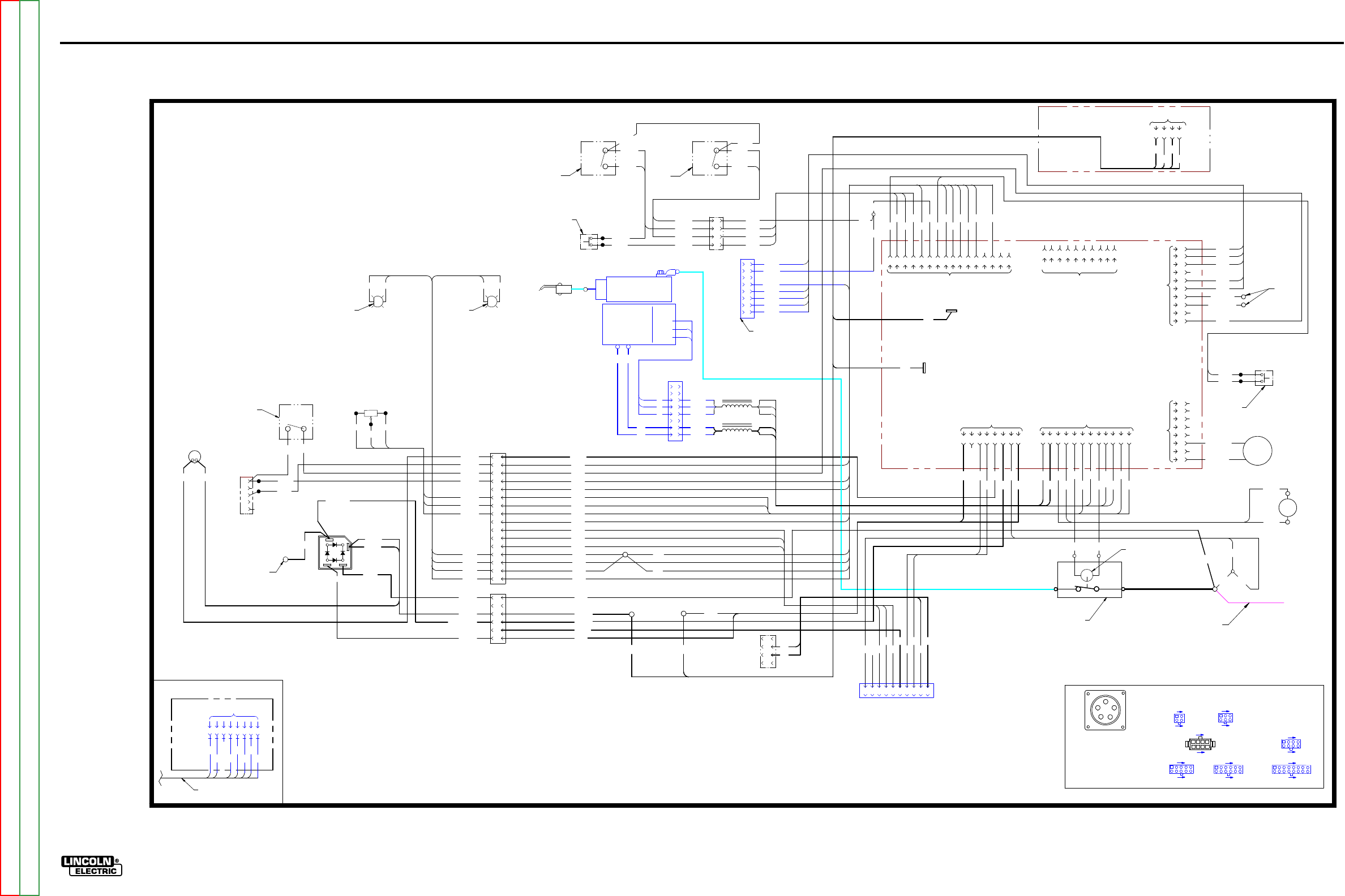
ElECTriCal DiaGrams G-5
lN-25™ prO
WiriNG DiaGram - lN-25 prO - CODEs 11746, 11747 (G5681-3)
CONTROL P.C
.
BOARD
WIRING DIAGRAM- LN-25 PRO ANALOG
A.01
G5681-3
FEED
PLATE
P20/J20
8
M
OT
O
R
/
GEARBOX
W
R
TACH
U
B
53
1
B
B
W
69
0
69
1
GAS
SOLENOID
TRIGGER
INTERLOCK
/
2STEP
J3 5
6
3
4
2
1
R
U
B
5
6
3
4
2
1
7
8
J6
1 2 3456789
10111213141516
53
7
53
4
55
1
55
0
7
6
5
4
3
2
1
N
OT
E
S:
N.
A. PI
N
NEARES
T T
H
E
FL
A
T
EDG
E
OF
L
E
D
LEN
S
(A
NOD
E)
A
LI
GN
S
W
IT
H
W
HI
TE
LEA
D
OF
L
E
D
SOCKE
T.
N.
B.
SW
IT
CHE
S
SHOW
N
FR
O
M
REA
R
CONNE
CT
IO
N
SI
D
E
OF
S
W
IT
C
H.
N.D.
CONNE
CT
"
EX
TR
A
" T
O
"T
ORQUE
"
O
N
EX
TR
A
TO
RQU
E
MODEL
S
ONL
Y.
1
GAS PURGE
PUSHBUTTON
SWITCH
S1
S3
COLD
FEED
2
3
4
53
0A
53
0
52
3
58
7
58
7A
P16/J16
72
1A
50
0
62
2
57
5
57
6
N.B.
N.B.
N.B.
L5
L4
CC
/
CV
S2
52
3A
N.B.
1234
J5 J4
1234567
8
9
10 11 12
9
10
J2
57
7
1B
1W
2B
2W
50
0
62
2
50
9C
50
9E
50
9
50
9E
61
0
70
7
53
0
69
0
57
5
57
8
53
1
60
1
57
6
53
7
61
2
58
7
60
6
60
7
60
5
60
8
50
7
57
7
69
1
53
4
1W
2W 3B
4B
P60
61
2
52
3
50
9A
50
9D
50
9D
53
0A
52
3A
58
7A
50
9C
PO
ST-FL
OW BURNBACK
TIMER KIT
(
OPTIONA
L)
J60
8
60
1
50
9B
60
5
60
6
60
7
60
8
765
43
2
1
70
7
61
0
77
C
76
C
75
C
1 2 3456789
10
J1
TO P60
ON
HARN
ESS
G
ENER
A
L
INFOR
MAT
ION
EL
EC
T
RIC
A
L
SYMBOLS P
ER
E1537
LE
AD
CO
L
OR COD
ING
B
- B
L
AC
K
W
-
W
HI
TE
50
7
57
8CO
NT
A
CT
O
R
C
OIL
CO
NTA
CTO
R
67
C
50
9B
50
9A
50
9
8
7
6
5
4
3
2
1
60
1
50
9B
60
5
60
6
60
7
60
8
55
0
55
1
75
C
76
C
77
C
41
42
J18
1
2
3
4
41
42
EX
TR
A
TO
RQUE
7
8
5678
67
E
21
E
2A
4A
CO
NNE
CTS
TO T
IMER
KIT
70
8
66
7
4A
2A
72
1A
67F
82
1B
62
1
70
8
67
C
66
7C
62
1
82
1B
67
E
67F
67
D
4B
3B
4B
N.
O.
N.
O.
(SHOWN
I
NCV)
(SHOWN
I
N2STEP)
66
7D
66
7E
66
7
INP
UT ELE
CT
RODE
C
ABLE CO
NNE
CTI
ON
21
E
1
2
P17/J17
3
4
5
6
1
2
3
4
5
6
7
8
9
10
11
12
13
14
15
16
P7/J7
J15 123456789
10
J1, J
2, J
15
C
AVI
TY
NU
MBE
RIN
G SEQ
UENCE
(VI
EW
ED FROM COMPONENT
S
IDE OF
P
.C.
BO
ARD
)
6
5
10
1
J6, J
7
9
8
16
1
4
6
1
3
J3, J
5, J
9,
J2
0, J
60
5
4
8
1
J1
2, J
17
A
B
C
DE
J14
J1
1, J
1
6,
J1
8, J
61
3
4
1
2
J4
7
6
12
1
J1
9
4
1
5
8
B1
B2
MOTOR FILTER P.C
.
BOARD
1234
J61
66
7DB1
66
7E B2
55
5
55
5
S4
BLACK
RED
FAN
+
-
N.D
.
WOR
K
A
WOR
K
B
D1
TO
WORK
C
LIP
62
1A
WOR
K
A
66
7A
67
B
66
7A
67
B
66
7B
57
7A
2W
2B
1W
1B
72
1
62
1A
WIRE FEED SPEED
CONTROL
POTENTIOMETER
R1
10
K2W
57
7A
57
5A
57
6A
ARC
VOLTMETER
72
1
66
7B
+
VM
YELLOW
THERMAL
LED
57
6A
50
0A
57
5A
62
2A
E
D
C
B
50
0A
TRIGGER
CONNECTOR
62
2A
P14
A
AC
AC
BRIDGE
RECTIFIER
+
-
62
2B
55
5A
55
5A
2B
N.A.
2W
1B
N.A.
1W
POLARITY
LED
S5
WFS RANGE
SWITCH
N.B.
G-5
NOTE: This diagram is for reference only. It may not be accurate for all machines covered by this manual. The wiring diagram specific to your code is pasted inside one of the enclosure panels of your machine.
Return to Section TOC Return to Section TOC Return to Section TOC Return to Section TOC
Return to Master TOC Return to Master TOC Return to Master TOC Return to Master TOC
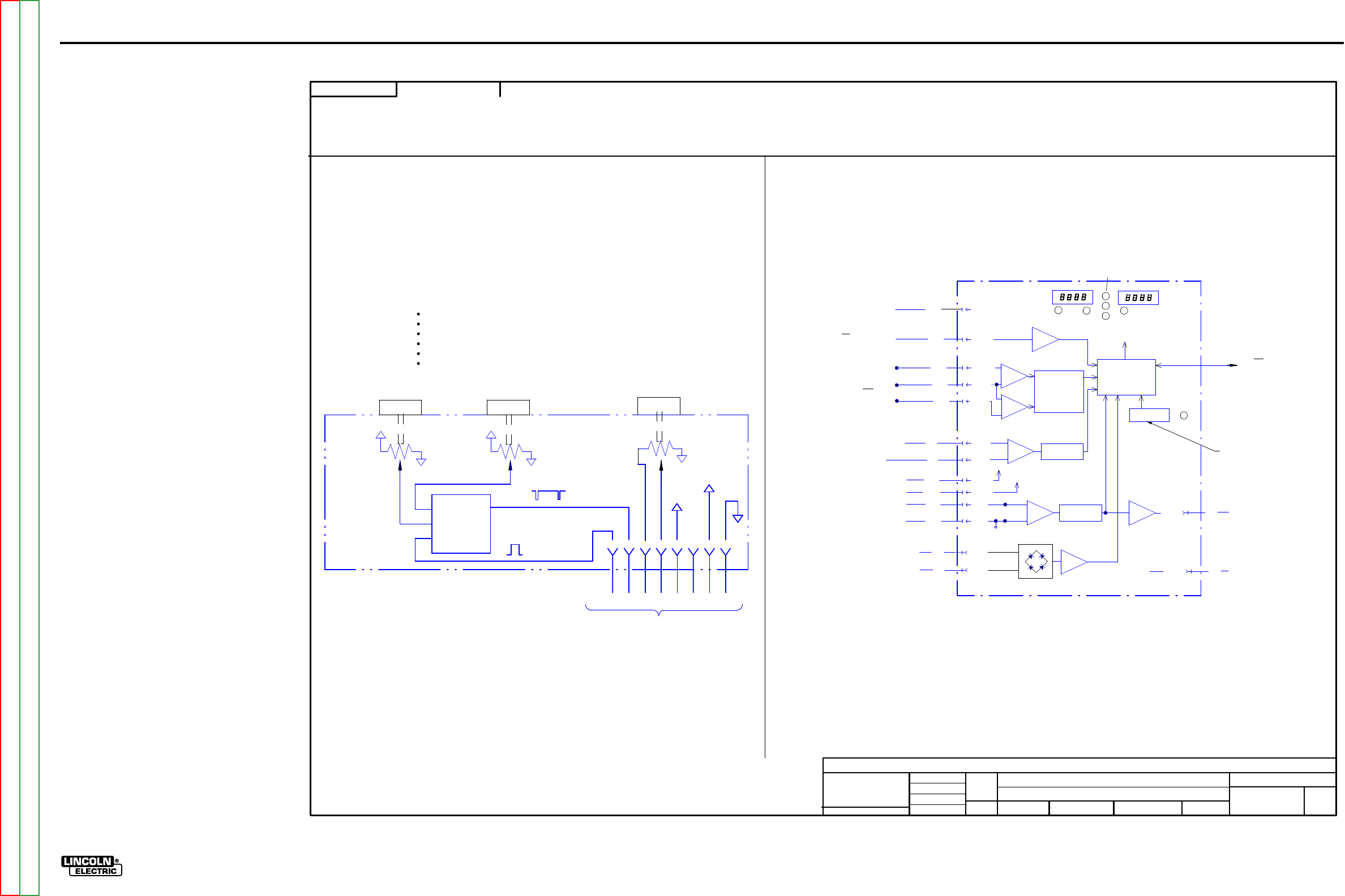
ElECTriCal DiaGrams G-6
lN-25™ prO
sChEmaTiC - lN-25 prO - COmplETE maChiNE CODEs 11387, 11388 - (G5683) pG1
SOLID EDGE
G5683
LN
-25 P
RO
MAC
HI
N
E SC
HEM
ATIC
NONE
-
DO NO
T
SC
AL
E
T
HIS DR
A
WING
EQ
UIP
M
ENT
TYPE:
SUBJECT:
UF
CR
M39437
2
PAGE ___ OF
___
2
E
NGI
N
EE
RI
NG
CO
NT
RO
LLE
D
MA
NU
FA
CT
URE
R:
No
THIS DOCUMENT CONTAINS PROPRIETAR
Y
INFORMATION OWNED B
Y
LINCOLN GLOBA
L, INC.
AND MA
Y
NOT BE DUPLICATED, COMMUNICATED
TO O
THER PARTIES OR US
ED FOR
AN
Y
PURPOS
E WITHOU
T
THE EXPRES
S WRIT
TEN PERMISSION
OF LINCOLN GLOBAL, INC.
PRO
PRIETARY & C
ONFIDENTIAL:
R
EVISED LEA
D
S GO
ING TO P17.
t
MAT
ERI
A
L TO
L
ER
ANC
E ("
"
) TO A
GR
EE
WITH
PU
B
LI
SH
ED
ST
ANDARD
S.
ON A
LL
AN
GL
E
S I
S ± .5 OF
A D
E
GR
EE
ON
3
PLACE
D
E
CIM
ALS
IS
± .
00
2 i
n.
(
±
0.
0
5
mm)
ON 2
PL
AC
E D
ECIM
AL
S I
S ± .02 in. (
±
0.5 mm)
UNLESS OTHERWISE SPECIFIED TOLERANCE:
M
ANUF
ACTURING TO
L
ER
ANC
E
P
ER
E
2056
CHAN
GE
D
ET
AIL:
REFER
ENCE:
SC
ALE:
M
ATER
IAL
DI
SP
OS
ITI
ON:
APPR
OV
AL
DATE
:
PROJ
ECT
NU
M
BER:
DOCUMEN
T
NUMBER:
DOCUMEN
T
REV
ISI
ON:
UN
I
TS
:
IF PR
IN
T
ED
@ A
2
SIZ
E
IN
CH 1
1/16/2
007
d
di
e
tz
ENYEDY
-
DRAWN BY:
ENGINEER:
CLE
VE
L
AND
APPROVED:
CONTROL:
C
G5683
Insight
LN-25 PRO WIRE FEEDER
MICROCONTRO
L
LER
SETUP
PUSHBUTTON
SERIAL
SPI
C
OMMUNICATION
T
OJ1
CONTROL
PC BOARD
VOL
TAGE
MEASUREMENT
OF REMOTE
VOL
TS
POTEN
TIOME
TER
ARC VOLTAGE
FEEDB
ACK
ARC CURRE
NT
FEEDB
ACK
+
-
+
-
J10-12
J12-4
J12-1
J10-14
J10-16
J10-15
J10-11
J10-6
J10-8
J10-1
J10-2
J10-9
J10-4
-15V
+15V
COM
{+4V = +500A
-4V = -500A
0V=RUN
I
NENABLED
T
OSW
IT
CH S5 RUN
I
N
77B
76B
75B
{
TO REMOTE VOLTS
POTEN
TI
OMETER R2
AND POWER SOURCE
ELECTRODE
WORK
41
42
67
21
PR
ESE
T
P
.C.
BOA
RD CIRCUIT
(LOCATED
O
NCAS
E
FRONT)
SCHE
MATIC
=
G4748
804
802
801
805
{
{
702
701
{J10-10
WFS/AMPS D
ISPLA
Y
VOLTS DISPLA
Y
7 SEGMENT
DISPLA
YS
(2 e
ach)
SIGNALS TO
DISPLA
Y
& LED
VOLTS
WFS
AMPS
MOTOR
THERMAL
3 LEDs
set
=WFS
actual = AMP
S
SPI
(10 leads)
708
SETUP
PUSHBU
TT
ON
(BOARD MOUNTED
)
J6-8 707
-15V
INPUT
POWER
SETUP
LED
CONTROL CABLE
I
NPU
T
POWER
DETEC
TI
ON
(<18 VAC
T
ODETEC
T)
ARC CURREN
T
MEASUREMENT
FOR DISPLAY & ARC ESTABLISHED
ARC VOLTAGE
MEASUREMENT
FOR DISPLAY
Timer
Board Summary
Has potentiometers for
B
urnback
, Preflow
and
P
ostflow.
Preflow
range
from
0
ms
to 10s.
Burnback range
from
0 to 25
0 m
s.
Postflow range
from
5
0ms
to 10 s.
Receives “Gas Flow Enable” signal.
Outputs 1
6
ms pulses to turn Gas Flow On
/
Off.
TIMER KIT
(OPTIONAL)
SCHEMATIC =
M21342
J60-6
60
1
50
9B
60
5
60
7
60
8
60
6A
J60-5
J60-8 J60-7 J60-1
J60-2
5V
COM
(LOCATED
B
EHIND
W
IRE
REE
L
COVER)
(LOCATED
O
NCAS
E
FRONT)
TIMER
P
.C.
BOA
RD CIRCUIT
POSTFLO
W
POT.
PREFLOW
POT.
TOG
GLE GAS FLOW
ON/OFF
5V SIGNAL
GAS FLOW
ENABLE
MICROCONTRO
L
LER
J60-4
1
5V
OUTPU
T
1
5V SIGNAL
1
5 ms PULSES
+5V
COM
+5V
COM
4B
TO
C
ONTR
OL B
D.
(VIA P60 plug)
BURNBAC
K
POT.
ADJU
ST KNOB
COM
1
0K
CW= +5
CCW= 0V
+5V +5V
1
0K
+5V
1
0K
ADJU
ST KNOB
ADJU
ST KNOB
ARC ESTABLISHED
OUTPUT
IF V> 10V RELATIVE TO COMMON
0
V= ARC NOT ESTABLISHED
TO
CONTROL
BOARD
(VIA P7)
FR
OM
CONTROL
BOARD
(VIA P7)
NOT
USED
J60-3
G-6
NOTE: This diagram is for reference only. It may not be accurate for all machines covered by this manual.
Return to Section TOC Return to Section TOC Return to Section TOC Return to Section TOC
Return to Master TOC Return to Master TOC Return to Master TOC Return to Master TOC
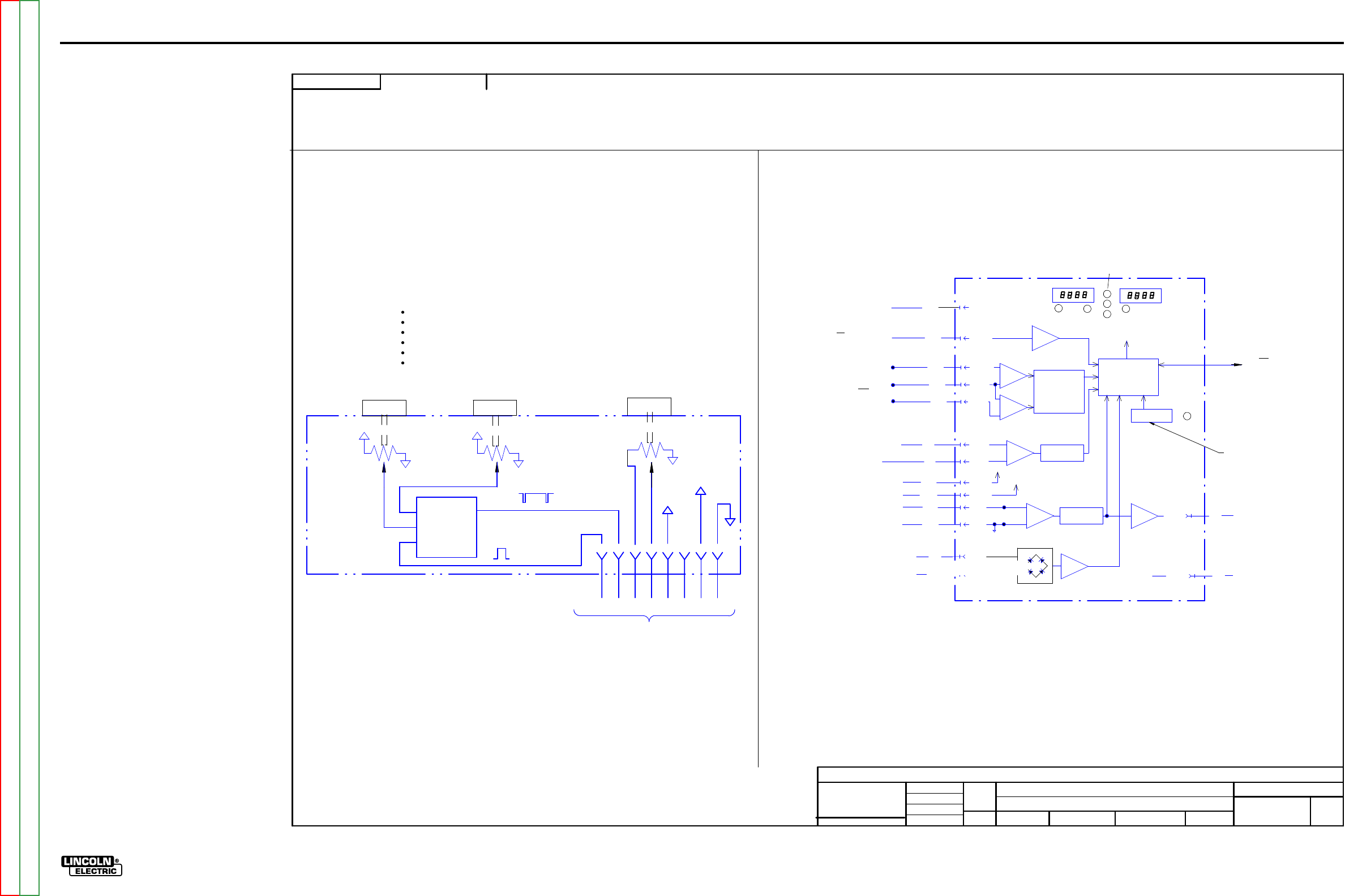
ElECTriCal DiaGrams G-7
lN-25™ prO
sChEmaTiC - lN-25 prO - COmplETE maChiNE CODEs 11387, 11388 - (G5683) pG2
G5683
LN
-25 P
RO
MAC
HI
N
E SC
HEM
ATIC
NONE
-
DO NO
T
SC
AL
E
T
HIS DR
A
WING
EQ
UIP
M
ENT
TYPE:
SUBJECT:
UF
CR
M39437
2
PAGE ___ OF
___
2
E
NGI
N
EE
RI
NG
CO
NT
RO
LLE
D
MA
NU
FA
CT
URE
R:
No
THIS DOCUMENT CONTAINS PROPRIETAR
Y
INFORMATION OWNED B
Y
LINCOLN GLOBA
L, INC.
AND MA
Y
NOT BE DUPLICATED, COMMUNICATED
TO O
THER PARTIES OR US
ED FOR
AN
Y
PURPOS
E WITHOU
T
THE EXPRES
S WRIT
TEN PERMISSION
OF LINCOLN GLOBAL, INC.
PRO
PRIETARY & C
ONFIDENTIAL:
R
EVISED LEA
D
S GO
ING TO P17.
t
MAT
ERI
A
L TO
L
ER
ANC
E ("
"
) TO A
GR
EE
WITH
PU
B
LI
SH
ED
ST
ANDARD
S.
ON A
LL
AN
GL
E
S I
S ± .5 OF
A D
E
GR
EE
ON
3
PLACE
D
E
CIM
ALS
IS
± .
00
2 i
n.
(
±
0.
0
5
mm)
ON 2
PL
AC
E D
ECIM
AL
S I
S ± .02 in. (
±
0.5 mm)
UNLESS OTHERWISE SPECIFIED TOLERANCE:
M
ANUF
ACTURING TO
L
ER
ANC
E
P
ER
E
2056
CHAN
GE
D
ET
AIL:
REFER
ENCE:
SC
ALE:
M
ATER
IAL
DI
SP
OS
ITI
ON:
APPR
OV
AL
DATE
:
PROJ
ECT
NU
M
BER:
DOCUMEN
T
NUMBER:
DOCUMEN
T
REV
ISI
ON:
UN
I
TS
:
IF PR
IN
T
ED
@ A
2
SIZ
E
IN
CH 1
1/16/2
007
d
di
e
tz
ENYEDY
-
DRAWN BY:
ENGINEER:
CLE
VE
L
AND
APPROVED:
CONTROL:
C
G5683
I i h
LN-25 PRO WIRE FEEDER
MICROCONTRO
L
LER
SETUP
PUSHBUTTON
SERIAL
SPI
C
OMMUNICATION
T
OJ1
CONTROL
PC BOARD
VOL
TAGE
MEASUREMENT
OF REMOTE
VOL
TS
POTEN
TIOME
TER
ARC VOLTAGE
FEEDB
ACK
ARC CURRE
NT
FEEDB
ACK
+
-
+
-
J10-12
J12-4
J12-1
J10-14
J10-16
J10-15
J10-11
J10-6
J10-8
J10-1
J10-2
J10-9
J10-4
-15V
+15V
COM
{+4V = +500A
-4V = -500A
0V = RUN
I
NENABLED
T
OSW
IT
CH S5 RUN
I
N
77B
76B
75B
{
TO REMOTE VOLTS
POTEN
TI
OMETER R2
AND POWER SOURCE
ELECTRODE
WORK
41
42
67
21
PR
ESE
T
P
.C.
BOA
RD CIRCUIT
(LOCATED
O
NCAS
E
FRONT)
SCHE
MATIC
=
G4748
804
802
801
805
{
{
702
701
{J10-10
WFS/AMPS D
ISPLA
Y
VOLTS DISPLA
Y
7 SEGMENT
DISPLA
YS
(2 e
ach)
SIGNALS TO
DISPLA
Y
& LED
VOLTS
WFS
AMPS
MOTOR
THERMAL
3 LEDs
set
=WFS
actual = AMP
S
SPI
(10 leads)
708
SETUP
PUSHBU
TT
ON
(BOARD MOUNTED
)
J6-8 707
-15V
INPUT
POWER
SETUP
LED
CONTROL CABLE
I
NPU
T
POWER
DETEC
TI
ON
(<18 VAC
T
ODETEC
T)
ARC CURREN
T
MEASUREMENT
FOR DISPLAY & ARC ESTABLISHED
ARC VOLTAGE
MEASUREMENT
FOR DISPLAY
Timer
Board Summary
Has potentiometers for
B
urnback
, Preflow
and
P
ostflow.
Preflow
range
from
0
ms
to 10s.
Burnback range
from
0 to 25
0m
s.
Postflow range
from
5
0ms
to 10 s.
Receives “Gas Flow Enable” signal.
Outputs 1
6
ms pulses to turn Gas Flow On
/
Off.
TIMER KIT
(OPTIONAL)
SCHEMATIC =
M21342
J60-6
60
1
50
9B
60
5
60
7
60
8
60
6A
J60-5
J60-8 J60-7 J60-1
J60-2
5V
COM
(LOCATED
B
EHIND
W
IRE
REE
L
COVER)
(LOCATED
O
NCAS
E
FRONT)
TIMER
P
.C.
BOA
RD CIRCUIT
POSTFLO
W
POT.
PREFLOW
POT.
TOG
GLE GAS FLOW
ON/OFF
5V SIGNAL
GAS FLOW
ENABLE
MICROCONTRO
L
LER
J60-4
1
5V
OUTPU
T
1
5V SIGNAL
1
5 ms PULSES
+5V
COM
+5V
COM
4B
TO
C
ONTR
OL B
D.
(VIA P60 plug)
BURNBAC
K
POT.
ADJU
ST KNOB
COM
1
0K
CW= +5
CCW= 0V
+5V +5V
1
0K
+5V
1
0K
ADJU
ST KNOB
ADJU
ST KNOB
ARC ESTABLISHED
OUTPUT
IF V> 10V RELATIVE TO COMMON
0
V= ARC NOT ESTABLISHED
TO
CONTROL
BOARD
(VIA P7)
FR
OM
CONTROL
BOARD
(VIA P7)
NOT
USED
J60-3
G-7
NOTE: This diagram is for reference only. It may not be accurate for all machines covered by this manual.
Return to Section TOC Return to Section TOC Return to Section TOC Return to Section TOC
Return to Master TOC Return to Master TOC Return to Master TOC Return to Master TOC
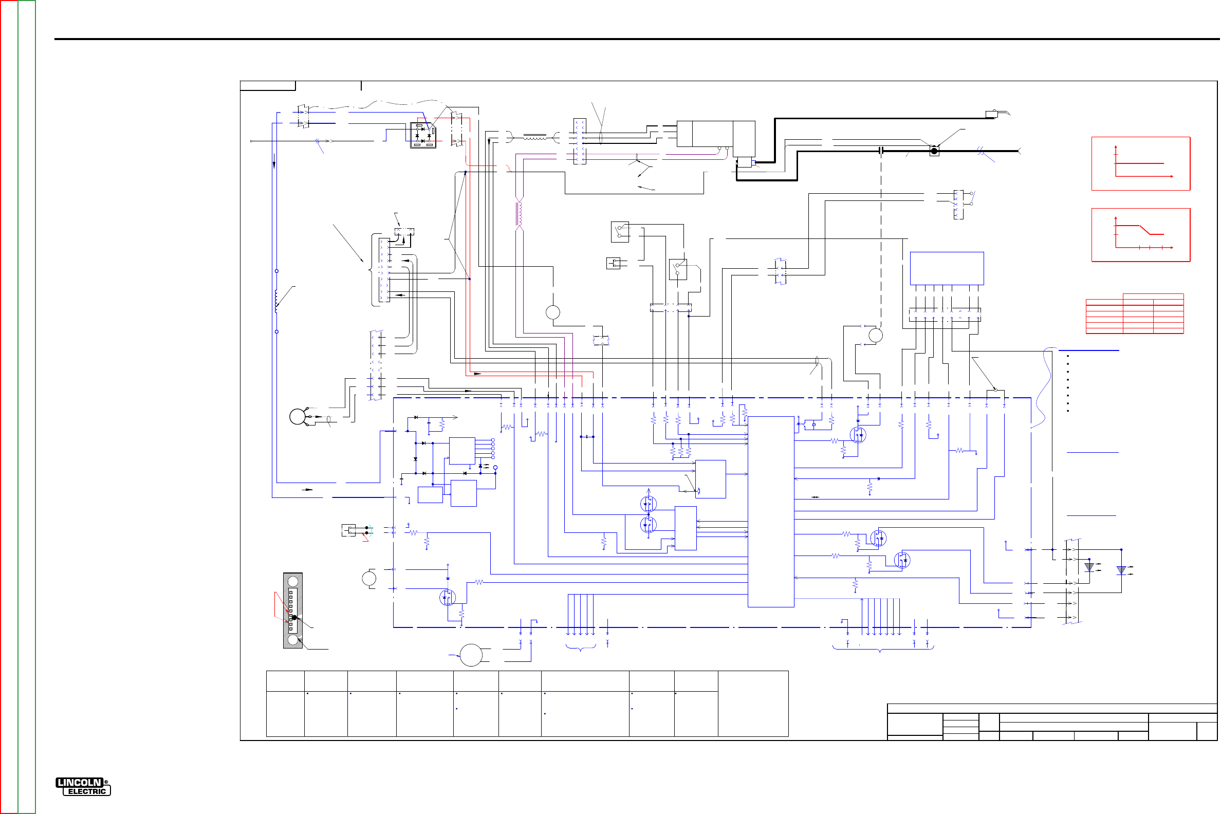
ElECTriCal DiaGrams G-8
lN-25™ prO
sChEmaTiC - lN-25 prO - COmplETE maChiNE CODEs 11507, 11508 - (G5683-1) pG1
G568
3-
1
LN
-25 P
RO
MAC
HI
N
E SC
HEM
ATIC
NONE
G5683
DO NO
T
SC
AL
E
T
HIS DR
A
WING
EQ
UIP
M
ENT
TYPE:
SUBJECT:
SCA
L
E:
NA
CR
M40936
1
PAGE ___ OF
___
2
E
NGI
N
EE
RI
NG
CO
NT
RO
LLE
D
MA
NU
FA
CT
URE
R:
No
THIS DOCUMENT CONTAINS PROPRIETAR
Y
INFORMATION OWNED B
Y
LINCOLN GLOBA
L, INC.
AND MA
Y
NOT BE DUPLICATED, COMMUNICATED
TO O
THER PARTIES OR US
ED FOR
AN
Y
PURPOS
E WITHOU
T
THE EXPRES
S WRIT
TEN PERMISSION
OF LINCOLN GLOBAL, INC.
PRO
PRIETARY & C
ONFIDENTIAL:
t
MAT
ERI
A
L TO
L
ER
ANC
E ("
"
) TO A
GR
EE
WITH
PU
B
LI
SH
ED
ST
ANDARD
S.
ON A
LL
AN
GL
E
S I
S ± .5 OF
A D
E
GR
EE
ON
3
PLACE
D
E
CIM
ALS
IS
± .
00
2 i
n.
(
±
0.
0
5
mm)
ON 2
PL
AC
E D
ECIM
AL
S I
S ± .02 in. (
±
0.5 mm)
UNLESS OTHERWISE SPECIFIED TOLERANCE:
M
ANUF
ACTURING TO
L
ER
ANC
E
P
ER
E
2056
MISC. UP
D
ATES PER SE
R
VICE
D
EPA
RTME
NT.
CHAN
GE
D
ET
AIL:
REFER
ENCE:
MA
T
ERI
AL
DIS
PO
SI
T
ION:
AP
PRO
VA
L
DA
T
E:
PROJ
EC
T
NUMBER:
DOCUMEN
T
NUMBER:
DOCUMEN
T
REV
ISI
ON:
IF PR
IN
T
ED
@ A
1
SIZ
E
UNI
T
S:
IN
CH
2/12/2
010
tpe
ar
n
ENYEDY
SCHO
LTI
DRAWN BY:
ENGINEER:
CLE
VE
L
AND
APPROVED:
CONTROL:
C
G5683-1
LN-25 PRO WIRE FEEDER
St
a
rt-Up
On power-
up,
the LN
-25 P
RO w
il
l
l
ight the
motor
thermal LE
D and
pol
ar
ity LE
D 2
-3 se
conds.
If the
feede
r i
s powered
-up with the trigge
r dep
re
ssed, weld
ing w
ill
not start un
ti
l the trigge
r i
s re
lea
sed and then depres
sed aga
in.
Note
s:
Motor over
cu
r
rent l
imit var
ie
s with WFS
.
FE
ED
PL
AT
E
67
C & 67
D
J4-10
1
4
3
2
6
5
P9
8
7
MOT
O
R /
GEARBOX
W
B
551
550
531
L4
537
534
72 H
Z TO 1.2 KHZ
R
-B 15.0 VD
C
B-
U 6.2 VD
C A
NY SPEED
(METE
R
D
EPE
NDE
NT
)
Mot
or i
s l
oc
ate
d
be
hi
nd
gl
ast
ic
pane
l
G
ear
bo
x rat
io
is
23.5:1
Motor c
ase i
s at
el
ectr
od
e pote
nti
al
From Power Sour
ce
(E
le
ctrode
C
onnect
ion
)
J4-7
0-5V PULSE SIGNAL
FREQUENC
Y
=
SPEED
WIRE FEED
SPEED
0V = MIN
SPEED
5V = MAX
SPEE
D
GAS PURGE
FLE
X
IBLE
PO
WE
R P.C. B
OA
RD
SCHE
MATIC
=
G4745
T
op
of
m
otor
Mot
or re
si
sta
nc
e
is
1.5
oh
ms
Leads Pass through
toroid 2 times. R
U
B
L
oc
at
e
d
on
C
as
e fro
nt
Leads Pass
through
toroid 2 times.
ISOLATED 2-4 TO
POWER SOU
RCE
BLACK
RED
FAN
+
-
S4
GAS PURGE
PUSHBUTTON
SWITCH
(
N.O
.)
61
2
61
0
13.5 VD
C W
HEN
NOT
D
EP
R
ESSE
D
J6-1
J6-7
J2-1
(LOCATED
I
NSIDE OF
CONTROL BOX)
FA
N BLOWS AIR AC
ROSS
CO
NT
RO
L PC BOA
R
D
CO
NTI
NO
U
SLY
AT
6200 RPMS.
GAS
SOLENOID
22 O COIL
0
VDC
OPEN
4 VDC CLOSED
12 VDC COIL
PWM
CO
NTROLLED
69
0
69
1J4-4
J4-3
J2-5
100K
ohm
+15V
J3-7
+5
V
J3-1
J3-2
J3-3
J3-4
J3-5
PROGRAMMING
PCB
FACTORY USE ONLY
GAS SOLENOID
-
+
WOR
K
C
LI
P
+35V
POWER
SUPPL
Y
POWER
SUPPL
Y
+5V SPI
+15V SPI
OVER
VOL
TAGE
PROTECTION
ISO
LED
3
5VDC
+5VDC
+15V ISO
-15V
C
OM
MO
TOR
SUPPL
Y
C
OM
J5-1
J5-8
62
1A
Located on
Case Fr ont
J4-11 J4-12
J4-6
10
0K
o
hm
+5
V
J3-6
J3-8
+5
V
S
PI
J4-9
1
0K
o
hm
+15V
COM
534
537
531
J4-1
J4-2
550
551
TACH
FEEDB
ACK
Model
Ranger 8,9
Classic
Ranger 250, 305
Commander 300,400,500
(Common Analog
Contr ol s)
V350
(Common Digi tal
Controls)
DC
-
400, 600
Square Wave TIG 300/355
Miller Inverters
STT II
K
2613
-1
K2613-2
K2613-3
Recommended
all CV
operation.
Recommended f or
CV o pera t io n.
(Wire Feed
Module R equired)
Rec ommended f or CV
operation.
Rec ommended
for CV
operation.
May be us ed for
pulse welding if
the welding
procedure is
qualified by the
cus tomer.
Rec ommended
for CV and CC
operation.
Not recommended for CC operation
because the customer may
experience short contactor life from
inductive nature of the power source.
Not recommended with high frequency
TIG starting.
Rec om me nd ed
for CV voltage
sens e operation.
Not
recommended for
use when pulse
welding.
Notrecommended
for STT oper
ation.
Note:
Most semiauto mati c wire
welding processes perform
better using constant voltage
power sources. Be sure the
proper power source is used
for your application. Contactor
life may be shortened in
applications using CC
machines with high OCV.
J5-6
J5-7
21D
67F
721
J5-5
AN
ALO
G
VOLTMET
ER
667B
721
-
+
TRIGGER
622
500
-15
+15
72
1 IS DRIV
EN NEGATIVE TO COMPENSATE
FOR THE METER FOR D
IODE DROP
ERROR
ON THE BRIDGE
METER
COMPENSATION
CIRCUIT
POLARITY
SENSE
PROGRAM
BURNBAC
K
M
OTO
R
D
RI
VE
CI
RC
UI
T
MO
TOR VOL
TAGE
MO
TOR CURRENT
BRAKE
DRIVE
BRAKE
D
RI
VE
PW
M
0.05K
oh
m
L5
J6-3
J6-2
587
530
J6-4
523
J6-6
509A
+15
V
COLD FEED
CC/VV
T
RI
GG
ER I
NT
ERLOC
K / 2 S
T
EP
S
1,
S
2
&S
3 L
oc
ate
d
on Wir
e
D
riv
e
P
an
el
CC
509D
CV
509E
TRI
GGE
R I
NT
E
RL
OCK
(N
OT
PRESE
NT
O
N
K2613-3)
S1
587
2-ST
EP
Lo
cat
ed
on Wir
e
D
riv
e
P
an
el
T
rig
ger I
nter
lo
ck
do
es
not
sto
p
w
eldi
ng
w
he
n th
e ar
c i
s br
ok
en.
P
ul
l a
nd r
el
ea
se t
o e
nd t
he
w
el
d.
509B
S2
523
S3
N.O.
C
OL
D F
EED
530A
509E
(LOCATED
A
T
REAR
O
F
FEEDER)
66
7C
0V=
CO
L
D FEE
D
(
N.O.)
15V=
CV
0V=
CC
15V=
2 STEP
0V=T
RIGGE
R
INTE
R
LO
CK
4B
606A
2
4
+15V
J5-4 J5-3
MOV
MACHINE
OUTPU
T
ENABLE
CONTAC
TOR DRIVE
COM
+35V J4-8J4-5
CO
NT
A
CT
OR
4
O COIL
0
VDC
OPEN
3
VDC CLOSED
12 VDC COIL
PWM
CO
NTROLLED
507
578
20
ohm
0V = OF
F
2
0msec ----
25
0msec
605 601
J2-6 J2-3
608
607
J2-7
COM
Y
ELLO
W
THERMAL
LED
COM
POLARITY LED
J6-11 1W
J6-14 B
+5V SPI
GREEN
POLARITY
LED
Y
ELL
OW
MOT
OR
TH
E
RM
AL
LE
D
ARC ESTABLISHED
J1-2 J1-1
+5V SPI +15V
J1-10
J1-8
J1-6
J1-5
J1-4
J1-9
J1-3
J1-7
SCLK
CS3
CS2
CS1
CS0
MOSI
MISO
SPI
DIGITA
lL COMMUNICATION
J6-8
-15V
GAS
ON - OF
F
GAS
FLOW
ENABLE
Lo
cat
ed
un
der
Wire
D
riv
e
P
an
el
(LOCATED
A
T
OUT
SI
D
E
REAR
O
F
FEEDER)
10K/2W
0 VD
C MI
N. WFS
5 VD
C MA
X
.
WFS
WI
R
E F
EE
D
SPEED
CO
NT
R
OL
P
OT
E
NTIOM
ET
ER
62
1
66
7
11
10
P7
12
Conn
ect
or
l
oc
at
ed
behin
d c
as
e
fro
nt
COM
15
14
(LOCATED
A
T
TOP
FRON
T
O
F
FEEDER)
MICRO
CONTROLLER
COM
MO
TOR
SUPPL
Y
6
8
7
5
1
3
4
6
2
8
7
9
10
J18
1
P16
L
oc
at
e
d
on
top
of m
ot
or
PLASTIC
HO
U
SE
D BOLTE
D
CO
NNE
CTIO
N
(BASE
CE
NTE
R)
TIMER KIT
P.C. B
OA
RD
(
OPTIO
NAL
)
SCHE
MATIC
=
M213
41
SEE
PAGE 2
L12081 2.6 V
@ 50
IPM
27
V @
700
IPM
L13084 2.6 V
@ 25
IPM
32
V @
400
IPM
0V
.=
TR
IG
GER
CLOSED
15
VDC
.=
TR
IG
GER
OPEN
Lo
cat
ed
on
C
as
e
F
ront
TRI
GGER
IN
P
UT
TRI
GGE
R
CONNE
CT
OR
J14
622A
500A
E
B
C
D
A
4
2
P7-1
67D
67C
66
7B
67
B
4
1
3
6
67C
67B
IN
HARN
ESS
CE
NTE
R BASE
AR
EA
P
7
=
16
PI
N
P
17
=
6
PI
N (
B
oth
are
lo
cat
ed on
lo
w
er fr
ont)
57
7A
57
6A
57
5A
57
7A
57
5A
57
6A
57
7A
57
6A
57
5A
77
C
76
C
75
C
531
537
534
FL
OW
METER
(O
UTSIDE BACK
OF CASE)
GOOD FO
R A
r, CO2,
CO
2/Ar BLEN
DS
40V MA
X.
21
B
.05
uF
60
0 V
70
7
608
607
J2-8
4B
gun connecto
r
25
TO 35
NOR
MAL
FL
O
W
RATE
BALL FLOAT
U
SE MID
D
LE OF
BALL TO SE
T
AD
J
UST VALVE
4 of 4
3 of 4
J6-9
J6-10
622
500
+15
V
2 of 2
P
17
P7
1 of 4
P7
When tach feed back is
lo
st,
the voltage to
the
motor is a
constant 10VD
C.
(c
ontro
l
led b
y so
ftware
)
P
17
ca
se
fron
t
str
ain
rel
ief
1 of 2
5
2 of 4
coppe
r
bar coppe
r
bar weld cable
13
2B
1B
R1
D1
ca
se
ba
ck
str
ain
rel
ief
509C
21
A
21
C
21E
JU
MPE
R TOGET
HE
R FO
R
EX
TRA TO
RQ
U
E MAC
HI
NE
P6
0
3
4
5
67
8
601
509B
605
2
1
3
42
J2-2
+5V
606
EX
TRA TO
RQ
UE
TAKEN WITH 40 V INP
UT
IN
C
V MODE.
667E 667D
66
7A
WFS limited by arc voltage when operating across the arc
Feeder Input Volts Standard Gear Extra Torque
15
280
210
17
340
235
21
440
400
24
520
400
27
600
400
Maximum WFS
EXTRA
TO
RQUE
Control
Boar d Summary
Conve r ts a rc power t o a u sa ble co ntro l c irc u it vol ta ge.
Rec ei ve s swit c h s ignals f rom T ri gger, Co ld F e ed , Gas P ur g e
Reads WFS potentiometer.
Commun icates w it h o pt io nal t im er ki t.
Control s motor spe ed wi t h P W M.
Turns Gas Solenoid on, off
, PWM
.
Reads t he motor t ac home ter.
O
perat
ing V
o
ltage=
15
-
110 VD
C.
Shut down
Voltage
=130
VDC
.
Thermal light turns on when shutdown voltage exceeded.
Code and Seri al numbers a re belo w Wir e D ri ve o n pl a st ic
housing Nameplate.
Ther mal “Yell ow” Li ght
Motor O
ver
Current
Motor and trigger disabled for 30 seconds.
Must retrigger to start welding after 30 seconds pass.
Shutdown Voltage exceeded
May occur with some inverters.
May occur with some CC machines with high
inductance.
Polarity “Green” Light
On=
Positive Polarity
Off= Negative Polarity
70
8J6-5 9
2W
J6-12
16
509B
The WFS range of the LN-
25 PRO
No
rmal Speed
= 40
- 700 IPM.
E
x
tra Torque
= 25
- 400 IPM.
Before 2-20-2009
After 2-20-2009
*Extra Torque
370 530 700
180* 257* 400*
3.5
4.5
3.5
4.5
Preset
WFS
Current
Level
Current
Level
Preset
WFS
77
C
76
C
75
C
N
ot pr
es
e
nt
o
n
K261
3-
3
J1
5
14 PIN
R
EMOTE
LEA
D
S ARE
PR
ESE
NT B
UT
NOT
U
SE
D I
N
THIS
U
NIT.
NOT
U
SE
D
LINE FILTE
R FO
R
NOISE ON
INVE
RTE
R I
NP
UT POWE
R.
LO
C
ATED ABOVE CO
NT
RO
L
BOAR
D O
N TOP
CE
NTE
R OF
CO
NT
RO
L BO
X
ASSEMBL
Y
62
1
G-8
NOTE: This diagram is for reference only. It may not be accurate for all machines covered by this manual.
Return to Section TOC Return to Section TOC Return to Section TOC Return to Section TOC
Return to Master TOC Return to Master TOC Return to Master TOC Return to Master TOC
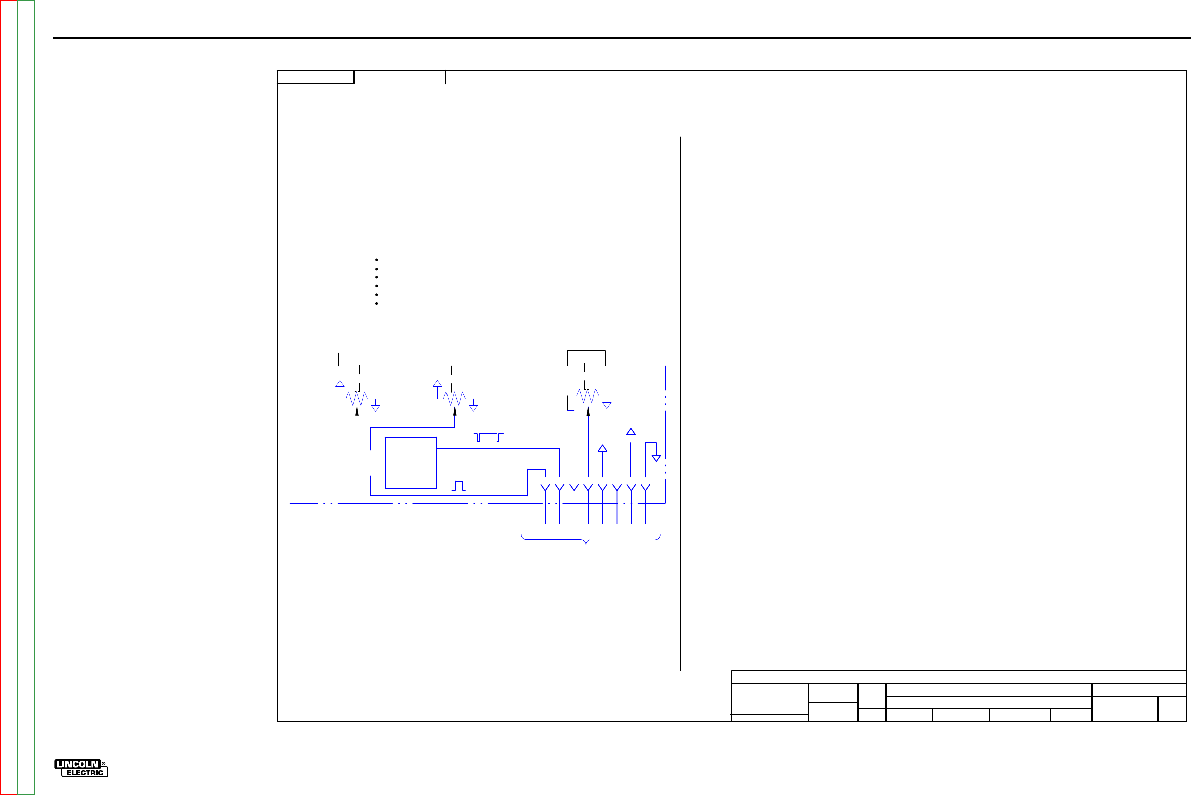
ElECTriCal DiaGrams G-9
lN-25™ prO
sChEmaTiC - lN-25 prO - COmplETE maChiNE CODEs 11507, 11508 - (G5683-1) pG2
SOLID EDGE
G568
3-
1
LN
-25 P
RO
MAC
HI
N
E SC
HEM
ATIC
NONE
G5683
DO NO
T
SC
AL
E
T
HIS DR
A
WING
EQ
UIP
M
ENT
TYPE:
SUBJECT:
NA
CR
M40936
2
PAGE ___ OF
___
2
E
NGI
N
EE
RI
NG
CO
NT
RO
LLE
D
MA
NU
FA
CT
URE
R:
No
THIS DOCUMENT CONTAINS PROPRIETAR
Y
INFORMATION OWNED B
Y
LINCOLN GLOBA
L, INC.
AND MA
Y
NOT BE DUPLICATED, COMMUNICATED
TO O
THER PARTIES OR US
ED FOR
AN
Y
PURPOS
E WITHOU
T
THE EXPRES
S WRIT
TEN PERMISSION
OF LINCOLN GLOBAL, INC.
PRO
PRIETARY & C
ONFIDENTIAL:
MISC. UP
D
ATES PER SE
R
VICE
D
EPA
RTME
NT.
t
MAT
ERI
A
L TO
L
ER
ANC
E ("
"
) TO A
GR
EE
WITH
PU
B
LI
SH
ED
ST
ANDARD
S.
ON A
LL
AN
GL
E
S I
S ± .5 OF
A D
E
GR
EE
ON
3
PLACE
D
E
CIM
ALS
IS
± .
00
2 i
n.
(
±
0.
0
5
mm)
ON 2
PL
AC
E D
ECIM
AL
S I
S ± .02 in. (
±
0.5 mm)
UNLESS OTHERWISE SPECIFIED TOLERANCE:
M
ANUF
ACTURING TO
L
ER
ANC
E
P
ER
E
2056
CHAN
GE
D
ET
AIL:
REFER
ENCE:
SC
ALE:
M
ATER
IAL
DI
SP
OS
ITI
ON:
APPR
OV
AL
DATE
:
PROJ
ECT
NU
M
BER:
DOCUMEN
T
NUMBER:
DOCUMEN
T
REV
ISI
ON:
UN
I
TS
:
IF PR
IN
T
ED
@ A
2
SIZ
E
IN
CH
2/12/2
010
tpe
ar
n
ENYEDY
SCHO
LTI
DRAWN BY:
ENGINEER:
CLE
VE
L
AND
APPROVED:
CONTROL:
C
G5683-1
Insight
LN-25 PRO WIRE FEEDER
TIMER KIT
(OPTIONAL)
SCHEMATIC =
M21342
J60-6
60
1
50
9B
60
5
60
7
60
8
60
6A
J60-5
J60-8 J60-7 J60-1
J60-2
5V
COM
(LOCATED
B
EHIND
W
IRE
REE
L
COVER)
(LOCATED
O
NCAS
E
FRONT)
TIMER
P
.C.
BOA
RD CIRCUIT
POSTFLO
W
POT.
PREFLOW
POT.
TOG
GLE GAS FLOW
ON/OFF
5V SIGNAL
GAS FLOW
ENABLE
MICROCONTRO
L
LER
J60-4
1
5V
OUTPU
T
1
5V SIGNAL
1
5 ms PULSES
+5V
COM
+5V
COM
4B
TO
C
ONTR
OL B
D.
(VIA P60 plug)
BURNBAC
K
POT.
ADJU
ST KNOB
COM
1
0K
CW= +5
CCW= 0V
+5V +5V
1
0K
+5V
1
0K
ADJU
ST KNOB
ADJU
ST KNOB
NOT
USED
J60-3
Timer
Board Su mmar y
Has pot entiome ters f or bu rn ba c k, p os tf low
and p
re
flow.
Preflow
range is 0 to 10
sec.
Burnback range is 0 to 0.25 sec.
Postflow range is 0.25 to 10 sec.
Rec ei ves “ Gas Fl ow Enable” s ignal.
Outputs 100 msec pulses to turn Gas Flow On, Gas
Flow Off.
G-9
NOTE: This diagram is for reference only. It may not be accurate for all machines covered by this manual.
Return to Section TOC Return to Section TOC Return to Section TOC Return to Section TOC
Return to Master TOC Return to Master TOC Return to Master TOC Return to Master TOC
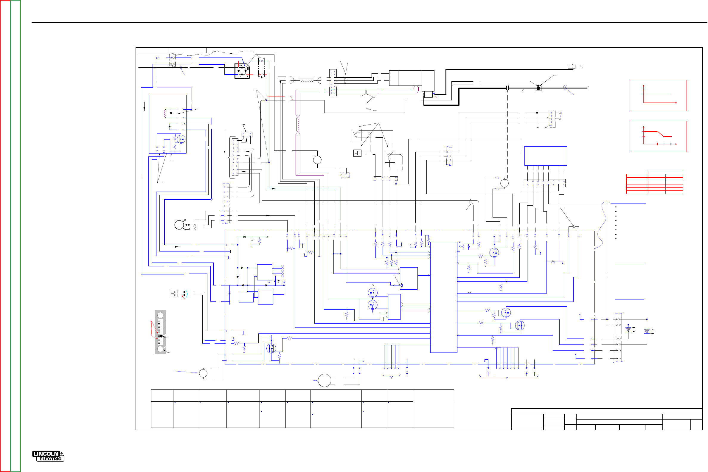
ElECTriCal DiaGrams G-10
lN-25™ prO
sChEmaTiC - lN-25 prO - COmplETE maChiNE CODEs 11620, 11621, 11716, 11717 - (G5683-2) pG1
G568
3-
2
LN
-25 P
R
O A
N
ALOG
MAC
HI
N
E SC
HEM
ATIC
NONE
G5683-
1
DO NO
T
SC
AL
E
T
HIS DR
A
WING
EQ
UIP
M
ENT
TYPE:
SUBJECT:
SCA
L
E:
UF
CR
M40943
1
PAGE ___ OF
___
2
E
NGI
N
EE
RI
NG
CO
NT
RO
LLE
D
MA
NU
FA
CT
URE
R:
No
THIS DOCUMENT CONTAINS PROPRIETAR
Y
INFORMATION OWNED B
Y
LINCOLN GLOBA
L, INC.
AND MA
Y
NOT BE DUPLICATED, COMMUNICATED
TO O
THER PARTIES OR US
ED FOR
AN
Y
PURPOS
E WITHOU
T
THE EXPRES
S WRIT
TEN PERMISSION
OF LINCOLN GLOBAL, INC.
PRO
PRIETARY & C
ONFIDENTIAL:
t
MAT
ERI
A
L TO
L
ER
ANC
E ("
"
) TO A
GR
EE
WITH
PU
B
LI
SH
ED
ST
ANDARD
S.
ON A
LL
AN
GL
E
S I
S ± .5 OF
A D
E
GR
EE
ON
3
PLACE
D
E
CIM
ALS
IS
± .
00
2 i
n.
(
±
0.
0
5
mm)
ON 2
PL
AC
E D
ECIM
AL
S I
S ± .02 in. (
±
0.5 mm)
UNLESS OTHERWISE SPECIFIED TOLERANCE:
M
ANUF
ACTURING TO
L
ER
ANC
E
P
ER
E
2056
R
ELEASE
D A.03 F
ROM "
X
".
CHAN
GE
D
ET
AIL:
REFER
ENCE:
MA
T
ERI
AL
DIS
PO
SI
T
ION:
AP
PRO
VA
L
DA
T
E:
PROJ
EC
T
NUMBER:
DOCUMEN
T
NUMBER:
DOCUMEN
T
REV
ISI
ON:
IF PR
IN
T
ED
@ A
1
SIZ
E
UNI
T
S:
IN
CH 1
1/6/
2009
tpe
ar
n
ENYEDY
BS
DRAWN BY:
ENGINEER:
CLE
VE
L
AND
APPROVED:
CONTROL:
A
G5683-2
LN-25 PRO WIRE FEEDER
St
a
rt-Up
On power-
up,
the LN
-25 P
RO w
il
l
l
ight the
motor
thermal LE
D and
pol
ar
ity LE
D 2
-3 se
conds.
If the
feede
r i
s powered
-up with the trigge
r dep
re
ssed, weld
ing w
ill
not start un
ti
l the trigge
r i
s re
lea
sed and then depres
sed aga
in.
Note
s:
Motor over
cu
r
rent l
imit var
ie
s with WFS
.
FE
ED
PL
AT
E
67
C & 67
D
J4-10
1
4
3
2
6
5
P9
8
7
MOT
O
R /
GEARBOX
W
B
551
550
531
L4
537
534
72 H
Z TO 1.2 KHZ
R
-B 15.0 VD
C
B-
U 6.2 VD
C A
NY SPEED
(METE
R
D
EPE
NDE
NT
)
Mot
or i
s l
oc
ate
d
be
hi
nd
gl
ast
ic
pane
l
G
ear
bo
x rat
io
is
23.5:1
Motor c
ase i
s at
el
ectr
od
e pote
nti
al
From Power Sour
ce
(E
le
ctrode
C
onnect
ion
)
J4-7
0-5V PULSE SIGNAL
FREQUENC
Y
=
SPEED
WIRE FEED
SPEED
0V = MIN
SPEED
5V = MAX
SPEE
D
GAS PURGE
FLE
X
IBLE
PO
WE
R P.C. B
OA
RD
SCHE
MATIC
=
G4783
T
op
of
m
otor
Mot
or re
si
sta
nc
e
is
1.5
oh
ms
Leads Pass through
toroid 2 times. R
U
B
L
oc
at
e
d
on
C
as
e fro
nt
Leads Pass
through
toroid 2 times.
ISOLATED 2-4 TO
POWER SOU
RCE
BLACK
RED
FAN
+
-
S4
GAS PURGE
PUSHBUTTON
SWITCH
(
N.O
.)
61
2
61
0
13.5 VD
C W
HEN
NOT
D
EP
R
ESSE
D
J6-1
J6-7
J2-1
(LOCATED
I
NSI DE OF
CONTROL BOX)
FA
N BLOWS AIR AC
ROSS
CO
NT
RO
L PC BOA
R
D
CO
NTI
NO
U
SLY
AT
6200 RPMS.
GAS
SOLENOID
69
0
69
1
J4-4
J4-3
J2-5
100K
ohm
+15V
J3-7
+5
V
J3-1
J3-2
J3-3
J3-4
J3-5
PROGRAMMING
PCB
FACTORY USE ONLY
GAS SOLENOID
-
+
WORK
C
LI
P
+35V
POWER
SUPPL
Y
POWER
SUPPL
Y
+5V SPI
+15V SPI
OVER
VOL
TAGE
PROTECTION
ISO
LED
3
5VDC
+5VDC
+15V ISO
-15V
C
OM
MO
TOR
SUPPL
Y
C
OM
J5-1
J5-8
62
1A
Located on Case Front
J4-11 J4-12
J4-6
10
0K
o
hm
+5
V
J3-6
J3-8
+5
V
S
PI
J4-9
1
0K
o
hm
+15V
COM
534
537
531
J4-1
J4-2
550
551
TACH
FEEDB
ACK
Model
Ranger 8,9
Classic
Ranger 250, 305
Commander 300,400,500
(Common Analog
Contr ol s)
V350
(Common Digi tal
Controls)
DC
-
400, 600
Square Wave TIG 300/355
Miller Inverters
STT II
K
2613
-1
K2613-2
Recommended
all CV
operation.
Recommended f or
CV o pera t io n.
(Wire F
eed
Module R equired)
Rec ommended f or CV
operation.
Rec ommended
for CV
operation.
May be us ed for
pulse welding if
the welding
procedure is
qualified by the
cus tomer.
Rec ommended
for CV and CC
operation.
Not recommended for CC operation
because the customer may
experience short contactor life from
inductive nature of the power source.
Not recommended with high frequency
TIG starting.
Rec om me nd ed
for CV voltage
sens e operation.
Not
recommended for
use when pulse
welding.
Notrecommended
for STT operation.
Note:
Most semiauto matic wire
welding processes perform
better using constant voltage
power sources. Be sure the
proper power sourceis used
for your application. Contactor
life may be shortenedin
applications using CC
machi nes wi th high OCV.
J5-6
J5-7
21D
67F
721
J5-5
AN
ALO
G
VOLTMET
ER
667B
721
-
+
TRIGGER
-15
+15
72
1 IS DRIV
EN NEGATIVE TO COMPENSATE
FOR THE METER FOR D
IODE DROP
ERROR
ON THE BRIDGE
METER
COMPENSATION
CIRCUIT
POLARITY
SENSE
PROGRAM
BURNBAC
K
M
OTO
R
D
RI
VE
CI
RC
UI
T
MO
TOR VOL
TAGE
MO
TOR CURRENT
BRAKE
DRIVE
BRAKE
D
RI
VE
PW
M
0.05K
oh
m
L5
J6-3
J6-2
587
530
J6-4
523
J6-6
509A
+15
V
COLD FEED
CC/VV
T
RI
GG
ER I
NT
ERLOC
K / 2 S
T
EP
S
1,
S
2
& S
3 L
oc
ate
d
on Wir
e
D
riv
e
P
an
el
CC
509D
CV
509E
TRI
GGE
R I
NT
E
RL
OCK
(N
OT
PRESE
NT
O
N
K2613-3)
S1
587
2-ST
EP
Lo
cat
ed
on Wir
e
D
riv
e
P
an
el
T
rig
ger I
nter
lo
ck
do
es
not
sto
p
w
eldi
ng
w
he
n th
e ar
c i
s br
ok
en.
P
ul
l a
nd r
el
ea
se t
o e
nd t
he
w
el
d.
509B
S2
523
S3
C
OL
D F
EED
530A
509E
(LOCATED
A
T
REAR
O
F
FEEDER)
66
7C
0V=
CO
L
D FEE
D
(
N.O.)
15V=
CV
0V=
CC
15V=
2 STEP
0V=T
RIGGE
R
INTE
R
LO
CK
4B
606A
2
4
+15V
J5-4 J5-3
MOV
MACHINE
OUTPU
T
ENABLE
CONTAC
TOR DRIVE
COM
+35V J4-8J4-5
CO
NT
A
CT
OR
4
O COIL
0
VDC
OPEN
3
VDC CLOSED
12 VDC COIL
PWM
CO
NTROLLED
507
578
20
ohm
0V = OF
F
2
0msec ----
25
0msec
605 601
J2-6 J2-3
608
607
J2-7
COM
Y
ELLO
W
THERMAL
LED
COM
POLARITY LED
J6-11 1W
J6-14 B
+5V SPI
GREEN
POLARITY
LED
Y
ELL
OW
MOT
OR
TH
E
RM
AL
LE
D
ARC ESTABLISHED
J1-2 J1-1
+5V SPI +15V
J1-10
J1-8
J1-6
J1-5
J1-4
J1-9
J1-3
J1-7
SCLK
CS3
CS2
CS1
CS0
MOSI
MISO
SPI
DIGITA
lL COMMUNICATION
J6-8
-15V
GAS
ON - OF
F
GAS
FLOW
ENABLE
Lo
cat
ed
un
der
Wire
D
riv
e
P
an
el
(LOCATED
A
T
OUT
SI
DE
REAR
O
F
FEEDER)
10K/2W
0 VD
C MI
N. WFS
5 VD
C MA
X
.
WFS
WI
R
E F
EE
D
SPEED
CO
NT
R
OL
P
OT
E
NTIOM
ET
ER
62
1
66
7
11
10
P7
12
Conn
ect
or
l
oc
at
ed
behin
d c
as
e fro
nt
COM
15
14
(LOCATED
A
T
TOP
FRON
T
O
F
FEEDER)
MICRO
CONTROLLER
COM
MO
TOR
SUPPL
Y
6
8
7
5
1
3
4
6
2
8
7
9
10
J18
1
P16
L
oc
at
e
d
on
top
of m
ot
or
PLASTIC
HO
U
SE
D BOLTE
D
CO
NNE
CTIO
N
(BASE
CE
NTE
R)
TIMER KIT
P.C. B
OA
RD
(
OPTIO
NAL
)
SCHE
MATIC
=
M213
41
SEE
PAGE 2
L12081 2.6 V
@ 50
IPM
27
V @
700
IPM
L13084 2.6 V
@ 25
IPM
32
V @
400
IPM
0V
.=
TR
IG
GER
CLOSED
15
VDC
.=
TR
IG
GER
OPEN
Lo
cat
ed
on
C
as
e
F
ront
TRI
GGER
IN
P
UT
TRI
GGE
R
CONNE
CT
OR
J14
622A
500A
E
B
C
D
A
P7-1
67D
67C
66
7B
67
B
4
1
3
6
67C
67B
IN
HARN
ESS
CE
NTE
R BASE
AR
EA
P
7
=
16
PI
N
P
17
=
6
PI
N (
B
oth
are
lo
cat
ed on
lo
w
er fr
ont)
57
7A
57
6A
57
5A
57
7A
57
5A
57
6A
57
7A
57
6A
57
5A
77
C
76
C
75
C
531
537
534
40V MA
X.
21
B
.05
uF
60
0 V
70
7
608
607
J2-8
4B
gun connecto
r
4 of 4
3 of 4
J6-9
J6-10
622
500
+15
V
2 of 2
P
17
P7
1 of 4
P7
When tach feed back is
lo
st,
the voltage to
the
motor is a
constant 10VD
C.
(c
ontro
l
led b
y so
ftware
)
P
17
ca
se
fron
t
str
ain
rel
ief
1 of 2
5
2 of 4
coppe
r
bar coppe
r
bar weld cable
13
2B
1B
R1
D1
ca
se
ba
ck
str
ain
rel
ief
509C
21
A
21
C
21E
JU
MPE
R TOGET
HE
R FO
R
EX
TRA TO
RQ
U
E MAC
HI
NE
P6
0
3
4
5
67
8
601
509B
605
2
1
3
42
J2-2
+5V
606
EX
TRA TO
RQ
UE
TAKEN WITH 40 V INP
UT
IN
C
V MODE.
66
7A
WFS limited by arc voltage when operating across the arc
Feeder Input Volts Standard Gear Extra Torque
15
280
210
17
340
235
21
440
400
24
520
400
27
600
400
Maximum WFS
EXTRA
TO
RQUE
Control
Boar d Summary
Conve r ts a rc power t o a u sa ble co ntro l c irc u it vol ta ge.
Rec ei ve s swit c h s ignals f rom T ri gger, Co ld F e ed , Gas P ur g e
Reads WFS potentiometer.
Commun icates w it h o pt io nal t im er ki t.
Control s motor spe ed wi t h P W M.
Turns Gas Solenoid on, off
, PWM
.
Reads t he motor t ac home ter.
O
perat
ing V
o
ltage=
15
-
110 VD
C.
Shut down
Voltage
=130
VDC
.
Thermal light turns on when shutdown voltage exceeded.
Code and Seri al numbers a re belo w Wir e D ri ve o n pl a st ic
housing Nameplate.
Ther mal “Yell ow” Li ght
Moto r O
ver
Current
Motor and trigger disabled for 30 seconds.
Must retrigger to start welding after 30 seconds pass.
Shutdown Voltage exceeded
May occur with some inverters.
May occur with some CC machines with high
inductance.
Polarity “Green” Light
On=
Positive Polarity
Off= Negative Polarity
70
8J6-5 9
2W
J6-12
16
509B
The WFS range of the LN-
25 PRO
No
rmal Speed
= 40
- 700 IPM.
E
x
tra Torque
= 25
- 400 IPM.
Before 2-20-2009
After 2-20-2009
*Extra Torque
370 530 700
180* 257* 400*
3.5
4.5
3.5
4.5
Preset
WFS
Current
Level
Current
Level
Preset
WFS
77
C
76
C
75
C
61
0
61
2
B1
B2
C2
C1
C1
C2
B1
B2
66
7D
66
7E
B2
B1
62
1
66
7D
25
TO 35
NOR
MAL
FL
OW
RATE
GOOD FO
R A
r, CO2,
CO
2/Ar BLEN
DS
(O
UTSIDE
BACK
O
F
CASE)
FL
OW
METER
22 O COIL
0
VDC
OPEN
4 VDC CLOSED
12 VDC COIL
PWM
CO
NTROLLED
BALL FLOAT
U
SE MID
D
LE
OF BALL TO
SET
AD
J
UST VALVE
NOT P
R
ESE
NT
ON S2750
5
J6
1-
1
J6
1-
3
J6
1-
4
J6
1-
2
J6
2-
2
J6
2-
1
MOTO
R
FI
LTE
R
P.
C.
BOAR
D
SCH
EM
A
TI
C=
S2
75
92 B
EFOR
E 6/15/2
00
9
S2
75
05 A
FTE
R
6/15/2
00
9
U
SE
D TO
DIS
CHA
RGE
POWER S
U
PPLY
CAP
AFTE
R A
HIG
H VOLTAGE
TRA
N
SIENT. LATER
R
ELO
C
ATED TO THE
CO
NT
RO
L BOAR
D.
U
SE
D FO
R FILTE
RI
NG
INVE
RTE
R
NOISE
J1
5
14 PIN
R
EMOTE
LEA
D
S ARE
PR
ESE
NT B
UT
NOT
U
SE
D I
N
THIS
U
NIT.
NOT
U
SE
D
J2-10
555
622
500
4
2
555
3
555A
622B
G-10
NOTE: This diagram is for reference only. It may not be accurate for all machines covered by this manual.
Return to Section TOC Return to Section TOC Return to Section TOC Return to Section TOC
Return to Master TOC Return to Master TOC Return to Master TOC Return to Master TOC
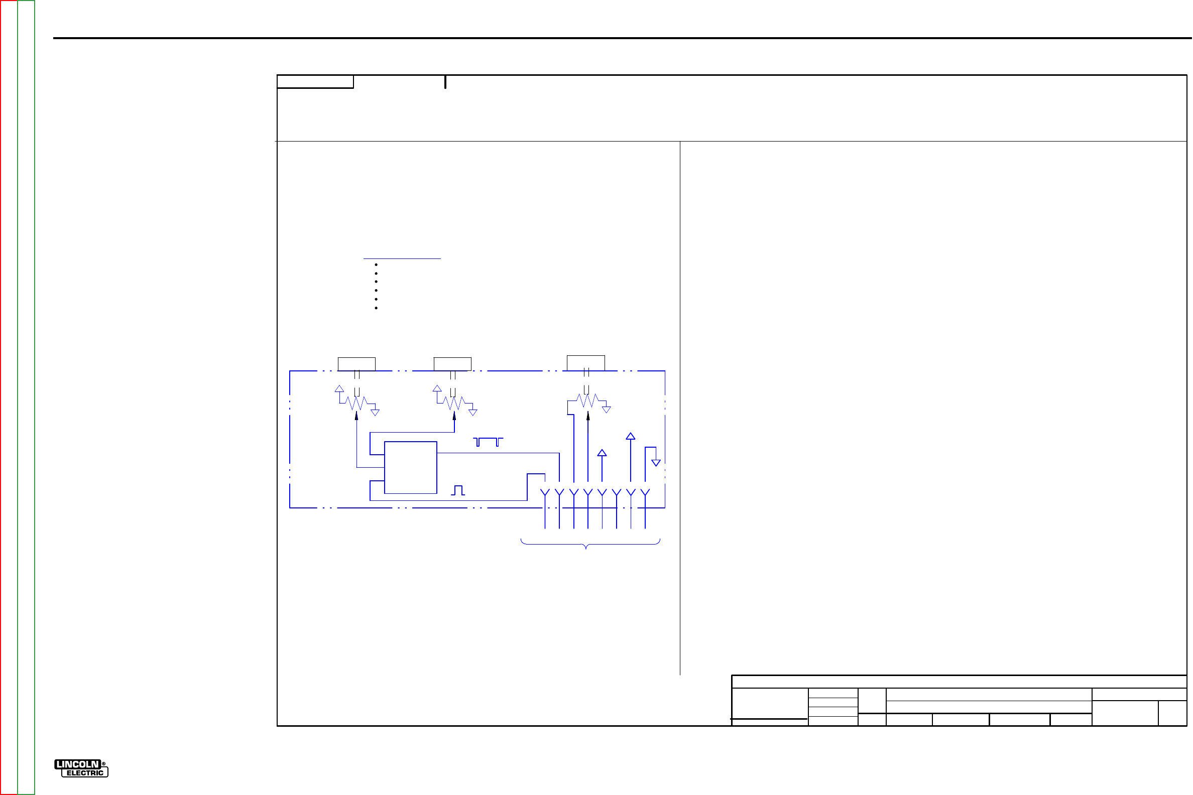
ElECTriCal DiaGrams G-11
lN-25™ prO
sChEmaTiC - lN-25 prO - COmplETE maChiNE CODEs 11620, 11621, 11716, 11717 - (G5683-2) pG2
G568
3-
2
LN
-25 P
R
O A
N
ALOG
MAC
HI
N
E SC
HEM
ATIC
NONE
G5683-
1
DO NO
T
SC
AL
E
T
HIS DR
A
WING
EQ
UIP
M
ENT
TYPE:
SUBJECT:
UF
CR
M40943
2
PAGE ___ OF
___
2
E
NGI
N
EE
RI
NG
CO
NT
RO
LLE
D
MA
NU
FA
CT
URE
R:
No
THIS DOCUMENT CONTAINS PROPRIETAR
Y
INFORMATION OWNED B
Y
LINCOLN GLOBA
L, INC.
AND MA
Y
NOT BE DUPLICATED, COMMUNICATED
TO O
THER PARTIES OR US
ED FOR
AN
Y
PURPOS
E WITHOU
T
THE EXPRES
S WRIT
TEN PERMISSION
OF LINCOLN GLOBAL, INC.
PRO
PRIETARY & C
ONFIDENTIAL:
R
ELEASE
D A.03 F
ROM "
X
".
t
MAT
ERI
A
L TO
L
ER
ANC
E ("
"
) TO A
GR
EE
WITH
PU
B
LI
SH
ED
ST
ANDARD
S.
ON A
LL
AN
GL
E
S I
S ± .5 OF
A D
E
GR
EE
ON
3
PLACE
D
E
CIM
ALS
IS
± .
00
2 i
n.
(
±
0.
0
5
mm)
ON 2
PL
AC
E D
ECIM
AL
S I
S ± .02 in. (
±
0.5 mm)
UNLESS OTHERWISE SPECIFIED TOLERANCE:
M
ANUF
ACTURING TO
L
ER
ANC
E
P
ER
E
2056
CHAN
GE
D
ET
AIL:
REFER
ENCE:
SC
ALE:
M
ATER
IAL
DI
SP
OS
ITI
ON:
APPR
OV
AL
DATE
:
PROJ
ECT
NU
M
BER:
DOCUMEN
T
NUMBER:
DOCUMEN
T
REV
ISI
ON:
UN
I
TS
:
IF PR
IN
T
ED
@ A
2
SIZ
E
IN
CH 1
1/6/
2009
tpe
ar
n
ENYEDY
BS
DRAWN BY:
ENGINEER:
CLE
VE
L
AND
APPROVED:
CONTROL:
A
G5683-2
LN-25 PRO WIRE FEEDER
TIMER KIT
(OPTIONAL)
SCHEMATIC =
M21342
J60-6
60
1
50
9B
60
5
60
7
60
8
60
6A
J60-5
J60-8 J60-7 J60-1
J60-2
5V
COM
(LOCATED
B
EHIND
W
IRE
REE
L
COVER)
(LOCATED
O
NCAS
E
FRONT)
TIMER
P
.C.
BOA
RD CIRCUIT
POSTFLO
W
POT.
PREFLOW
POT.
TOG
GLE GAS FLOW
ON/OFF
5V SIGNAL
GAS FLOW
ENABLE
MICROCONTRO
L
LER
J60-4
1
5V
OUTPU
T
1
5V SIGNAL
1
5 ms PULSES
+5V
COM
+5V
COM
4B
TO
C
ONTR
OL B
D.
(VIA P60 plug)
BURNBAC
K
POT.
ADJU
ST KNOB
COM
1
0K
CW= +5
CCW= 0V
+5V +5V
1
0K
+5V
1
0K
ADJU
ST KNOB
ADJU
ST KNOB
NOT
USED
J60-3
Timer
Board Su mmar y
Has pot entiome ters f or bu rn ba c k, p os tf low
and p
re
flow.
Preflow
range is 0 to 10
sec.
Burnback range is 0 to 0.25 sec.
Postflow range is 0.25 to 10 sec.
Rec ei ves “ Gas Fl ow Enable” s ignal.
Outputs 100 msec pulses to turn Gas Flow On, Gas
Flow Off.
G-11
NOTE: This diagram is for reference only. It may not be accurate for all machines covered by this manual.
Return to Section TOC Return to Section TOC Return to Section TOC Return to Section TOC
Return to Master TOC Return to Master TOC Return to Master TOC Return to Master TOC
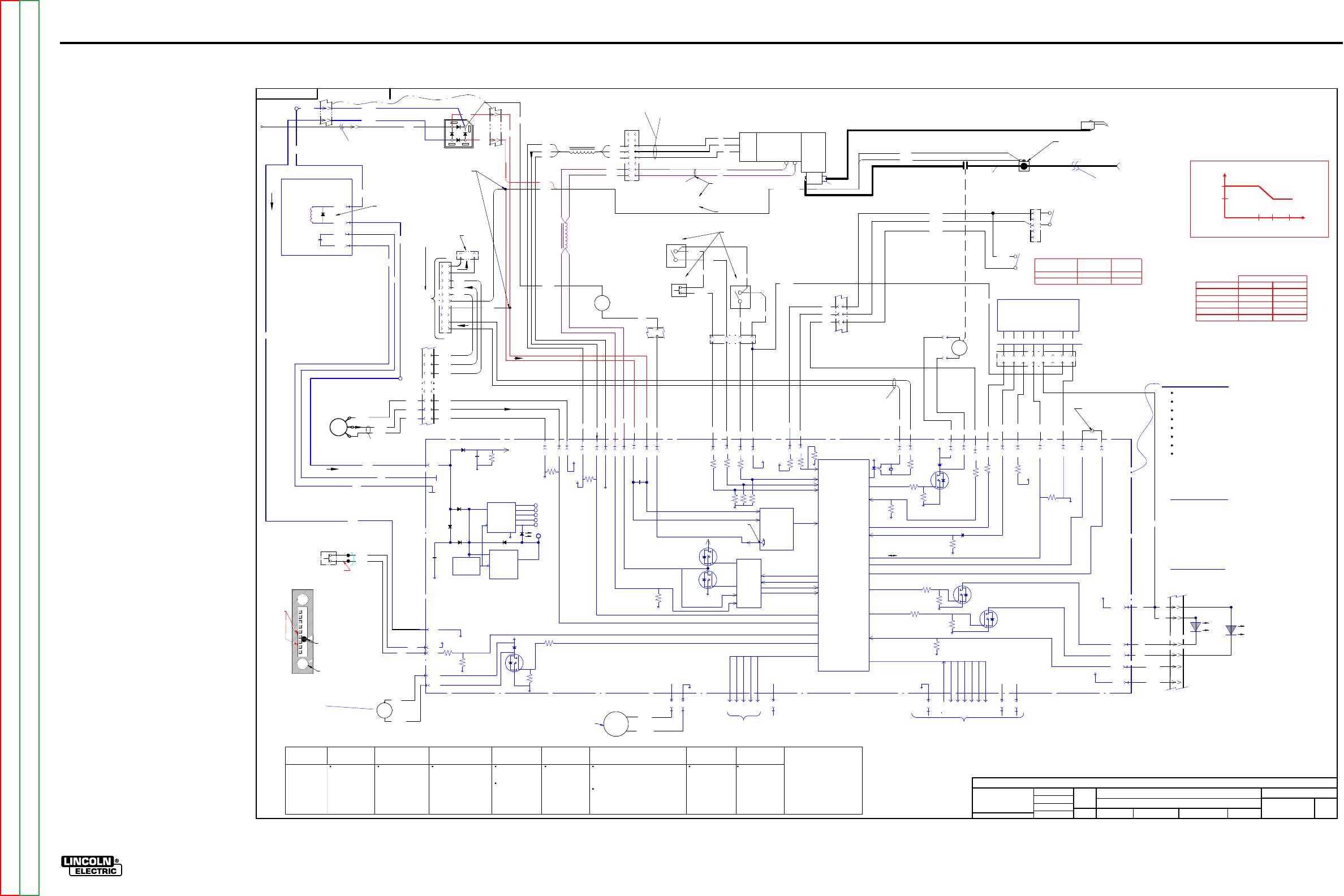
ElECTriCal DiaGrams G-12
lN-25™ prO
sChEmaTiC - lN-25 prO - COmplETE maChiNE CODEs 11746, 11747 - (G5683-3) pG1
G568
3-
3
LN
-25 P
R
O A
N
ALOG
MAC
HI
N
E SC
HEM
ATIC
NONE
G5683-
2
DO NO
T
SC
AL
E
T
HIS DR
A
WING
EQ
UIP
M
ENT
TYPE:
SUBJECT:
SCA
L
E:
NA
X
M6214-
C
1
PAGE ___ OF
___
2
E
NGI
N
EE
RI
NG
CO
NT
RO
LLE
D
MA
NU
FA
CT
URE
R:
No
THIS DOCUMENT CONTAINS PROPRIETAR
Y
INFORMATION OWNED B
Y
LINCOLN GLOBA
L, INC.
AND MA
Y
NOT BE DUPLICATED, COMMUNICATED
TO O
THER PARTIES OR US
ED FOR
AN
Y
PURPOS
E WITHOU
T
THE EXPRES
S WRIT
TEN PERMISSION
OF LINCOLN GLOBAL, INC.
PRO
PRIETARY & C
ONFIDENTIAL:
t
MAT
ERI
A
L TO
L
ER
ANC
E ("
"
) TO A
GR
EE
WITH
PU
B
LI
SH
ED
ST
ANDARD
S.
ON A
LL
AN
GL
E
S I
S ± .5 OF
A D
E
GR
EE
ON
3
PLACE
D
E
CIM
ALS
IS
± .
00
2 i
n.
(
±
0.
0
5
mm)
ON 2
PL
AC
E D
ECIM
AL
S I
S ± .02 in. (
±
0.5 mm)
UNLESS OTHERWISE SPECIFIED TOLERANCE:
M
ANUF
ACTURING TO
L
ER
ANC
E
P
ER
E
2056
A.02,
COMPLETELY REVISED
CHAN
GE
D
ET
AIL:
REFER
ENCE:
MA
T
ERI
AL
DIS
PO
SI
T
ION:
AP
PRO
VA
L
DA
T
E:
PROJ
EC
T
NUMBER:
DOCUMEN
T
NUMBER:
DOCUMEN
T
REV
ISI
ON:
IF PR
IN
T
ED
@ A
1
SIZ
E
UNI
T
S:
IN
CH
1/26/2
011
T.
PE
ARN
ENYEDY
-
DRAWN BY:
ENGINEER:
CLE
VE
L
AND
APPROVED:
CONTROL:
A.02
G5683-3
LN-25 PRO WIRE FEEDER
St
a
rt-Up
On power-
up,
the LN
-25 P
RO w
il
l
l
ight the
motor
thermal LE
D and
pol
ar
ity LE
D 2
-3 se
conds.
If the
feede
r i
s powered
-up with the trigge
r dep
re
ssed, weld
ing w
ill
not start un
ti
l the trigge
r i
s re
lea
sed and then depres
sed aga
in.
Note
s:
Motor over
cu
r
rent l
imit var
ie
s with WFS
.
FE
ED
PL
AT
E
67
C & 67
D
J4-10
1
4
3
2
6
5
P9
8
7
MOT
O
R /
GEARBOX
W
B
551
550
531
L4
537
534
72 H
Z TO 1.2 KHZ
R
-B 15.0 VD
C
B-
U 6.2 VD
C A
NY SPEED
(METE
R
D
EPE
NDE
NT
)
Mot
or i
s l
oc
ate
d
be
hi
nd
gl
ast
ic
pane
l
G
ear
bo
x rat
io
is
23.5:1
Motor c
ase i
s at
el
ectr
od
e pote
nti
al
From Power Sour
ce
(E
le
ctrode
C
onnect
ion
)
J4-7
0-5V PULSE SIGNAL
FREQUENC
Y
=
SPEED
WIRE FEED
SPEED
0V = MIN
SPEED
5V = MAX
SPEE
D
GAS PURGE
FLE
X
IBLE
PO
WE
R P.C. B
OA
RD
SCHE
MATIC
=
G4783
T
op
of
m
otor
Mot
or re
si
sta
nc
e
is
1.5
oh
ms
Leads Pass through
toroid 2 times. R
U
B
L
oc
at
e
d
on
C
as
e fro
nt
Leads Pass
through
toroid 2 times.
ISOLATED 2-4 TO
POWER SOU
RCE
BLACK
RED
FAN
+
-
S4
GAS PURGE
PUSHBUTTON
SWITCH
(
N.O
.)
61
2
61
0
13.5 VD
C W
HEN
NOT
D
EP
R
ESSE
D
J6-1
J6-7
J2-1
(LOCATED
I
NSI DE OF
CONTROL BOX)
FA
N BLOWS AIR AC
ROSS
CO
NT
RO
L PC BOA
R
D
CO
NTI
NO
U
SLY
AT
6200 RPMS.
GAS
SOLENOID
69
0
69
1
J4-4
J4-3
J2-5
100K
ohm
+15V
J3-7
+5
V
J3-1
J3-2
J3-3
J3-4
J3-5
PROGRAMMING
PCB
FACTORY USE ONLY
GAS SOLENOID
-
+
WORK
C
LI
P
+35V
POWER
SUPPL
Y
POWER
SUPPL
Y
+5V SPI
+15V SPI
OVER
VOL
TAGE
PROTECTION
ISO
LED
3
5VDC
+5VDC
+15V ISO
-15V
C
OM
MO
TOR
SUPPL
Y
C
OM
J5-1
J5-8
62
1A
Located on Case Front
J4-11 J4-12
J4-6
10
0K
o
hm
+5
V
J3-6
J3-8
+5
V
S
PI
J4-9
1
0K
o
hm
+15V
COM
534
537
531
J4-1
J4-2
550
551
TACH
FEEDB
ACK
Model Ranger 8,9 Classic Multiweld,
Ranger
s,
Vantages, Flextec
V350
DC
-400, 600 Square Wave TIG 300/355 Miller Inverters STT II
K2 6 13 -5
K2 6 13 -7
Recomm ended
al l CV
op er ati on .
Recommended for
CV operation.
(Wire Feed
Module Required)
Recommended for CV
and CC operation.
Recomm ended
for CV
operation.
May be used for
pulse welding if
the welding
procedure is
qualified by the
customer.
Recommended
for CV and CC
operation.
Not recommended for CC operation
be cau se th e cu s to me r m ay
exp er ie nc e sh or t c o nt ac to r li fe f ro
m
inductive nature of the power source.
Not recommended with hi gh frequency
TIG starting.
Recommended
for CV voltage
sense operation.
Not recommended
for STT operation.
Note:
Mos t s emi a uto mat ic w ir e
welding processes perform
better using constant vo ltage
power sou rces. Be sure the
proper power source is used
for your application. Con tact or
life may be shortened in
ap pl icatio ns us in g CC
machines with high OCV.
J5-6
J5-7
21D
67F
721
J5-5
AN
ALO
G
VOLTMET
ER
667B
721
-
+
TRIGGER
-15
+15
72
1 IS DRIV
EN NEGATIVE TO COMPENSATE
FOR THE METER FOR D
IODE DROP
ERROR
ON THE BRIDGE
METER
COMPENSATION
CIRCUIT
POLARITY
SENSE
PROGRAM
BURNBAC
K
M
OTO
R
D
RI
VE
CI
RC
UI
T
MO
TOR VOL
TAGE
MO
TOR CURRENT
BRAKE
DRIVE
BRAKE
D
RI
VE
PW
M
0.05K
oh
m
L5
J6-3
J6-2
587
530
J6-4
523
J6-6
509A
+15
V
COLD FEED
CC/VV
T
RI
GG
ER I
NT
ERLOC
K / 2 S
T
EP
S
1,
S
2
&S
3 L
oc
ate
d
on Wir
e
D
riv
e
P
an
el
CC
509D
CV
509E
TRI
GGE
R I
NT
E
RL
OCK
S1
587
2-ST
EP
Lo
cat
ed
on Wir
e
D
riv
e
P
an
el
T
rig
ger I
nter
lo
ck
do
es
not
sto
p
w
eldi
ng
w
he
n th
e ar
c i
s br
ok
en.
P
ul
l a
nd r
el
ea
se t
o e
nd t
he
w
el
d.
509B
S2
523
S3
C
OL
D F
EED
530A
509E
(LOCATED
A
T
REAR
O
F
FEEDER)
66
7C
0V=
CO
L
D FEE
D
(
N.O.)
15V=
CV
0V=
CC
15V=
2 STEP
0V=T
RIGGE
R
INTE
R
LO
CK
4B
606A
2
4
+15V
J5-4 J5-3
MOV
MACHINE
OUTPU
T
ENABLE
CONTAC
TOR DRIVE
COM
+35V J4-8J4-5
CO
NT
A
CT
OR
4
O COIL
0
VDC
OPEN
3
VDC CLOSED
12 VDC COIL
PWM
CO
NTROLLED
507
578
20
ohm
0V = OF
F
2
0msec ----
25
0msec
605 601
J2-6 J2-3
608
607
J2-7
COM
Y
ELLO
W
THERMAL
LED
COM
POLARITY LED
J6-11 1W
J6-14 B
+5V SPI
GREEN
POLARITY
LED
Y
ELL
OW
MOT
OR
TH
E
RM
AL
LE
D
ARC ESTABLISHED
J1-2 J1-1
+5V SPI +15V
J1-10
J1-8
J1-6
J1-5
J1-4
J1-9
J1-3
J1-7
SCLK
CS3
CS2
CS1
CS0
MOSI
MISO
SPI
DIGITA
lL COMMUNICATION
J6-8
-15V
GAS
ON - OF
F
GAS
FLOW
ENABLE
Lo
cat
ed
un
der
Wire
D
riv
e
P
an
el
(LOCATED
A
T
OUT
SI
DE
REAR
O
F
FEEDER)
10K/2W
0 VD
C MI
N. WFS
5 VD
C MA
X
.
WFS
WI
R
E F
EE
D
SPEED
CO
NT
R
OL
P
OT
E
NTIOM
ET
ER
62
1
66
7
11
10
P7
12
Conn
ect
or
l
oc
at
ed
behin
d c
as
e fro
nt
COM
15
14
(LOCATED
A
T
TOP
FRON
T
O
F
FEEDER)
MICRO
CONTROLLER
COM
MO
TOR
SUPPL
Y
6
8
7
5
1
3
4
6
2
8
7
9
10
J18
1
P16
L
oc
at
e
d
on
top
of m
ot
or
PLASTIC
HO
U
SE
D BOLTE
D
CO
NNE
CTIO
N
(BASE
CE
NTE
R)
TIMER KIT
P.C. B
OA
RD
(
OPTIO
NAL
)
SCHE
MATIC
=
M213
41
SEE
PAGE 2
L12081
-1 2.6 V
@ 50
IPM
27
V @
700
IPM
L13084
-1 2.6 V
@ 25
IPM
32
V @
400
IPM
0V
.=
TR
IG
GER
CLOSED
15
VDC
.=
TR
IG
GER
OPEN
Lo
cat
ed
on
C
as
e
F
ront
TRI
GGER
IN
P
UT
TRI
GGER
CONNE
CT
OR
J14
622A
500A
E
B
C
D
A
P7-1
67D
67C
66
7B
67
B
4
1
3
6
67C
67B
IN
HARN
ESS
CE
NTE
R BASE
AR
EA
P
7
=
16
PI
N
P
17
=
6
PI
N (
B
oth
are
lo
cat
ed on
lo
w
er fr
ont)
57
7A
57
6A
57
5A
57
7A
57
5A
57
6A
57
7A
57
6A
57
5A
77
C
76
C
75
C
531
537
534
40V MA
X.
21
B
.05
uF
60
0 V
70
7
608
607
J2-8
4B
gun connecto
r
4 of 4
3 of 4
J6-9
J6-10
622
500
+15
V
2 of 2
P
17
P7
1 of 4
P7
When tach feed back is
lo
st,
the voltage to
the
motor is a
constant 10VD
C.
(c
ontro
l
led b
y so
ftware
)
P
17
ca
se
fron
t
str
ain
rel
ief
1 of 2
5
2 of 4
coppe
r
bar coppe
r
bar weld cable
13
2B
1B
R1
D1
ca
se
ba
ck
str
ain
rel
ief
509C
21
A
21
C
21E
JU
MPE
R TOGET
HE
R FO
R
EX
TRA TO
RQ
U
E MAC
HI
NE
P6
0
3
4
5
6
78
601
509B
605
2
1
3
42
J2-2
+5V
606
EX
TRA TO
RQ
UE
TAKEN WITH 40 V INP
UT
IN
C
V MODE.
66
7A
WFS limited by arc voltage when operating across the arc
Feeder Input Volts Standard Gear Extra Torque
15
400 220
17
450 250
21
570 300
24
650 350
27
700 400
Maximum WFS
EXTRA
TO
RQUE
Control
Boar d Summary
Conve r ts arc pow e r t o a u sa ble con tro l c i rc uit volt ag e.
Rec ei ve s swit c h s ignals f r om T ri gg er, Cold F eed, Gas Pu r ge
Reads WFS potentiometer.
Commun icates w it h o pt io nal t im er ki t.
Control s motor spee d wi t h P W M.
Turns Gas Solenoid on, off
, PWM
.
Reads t he motor tac home ter.
O
perat
ing V
o
ltage=
15
-
110 VD
C.
Shut down
Voltage
=130
VDC
.
Thermal light turns on when shutdown voltage exceeded.
Code and Seri al n um bers a re b elow Wir e Dri ve o n pl a st ic
housing Nameplate.
Ther mal “Yell ow” Li ght
Mot o r O
ver
Current
Motor and trigger disabled for 30 seconds.
Must retrigger to start welding after 30 seconds pass.
Shutdown Voltage exceeded
May occur with some inverters.
May occur with some CC machines with high
inductance.
Polarity “Green” Light
On=
Positive Polarity
Off= Negative Polarity
70
8J6-5 9
2W
J6-12
16
509B
77
C
76
C
75
C
61
0
61
2
B1
B2
B1
B2
66
7D
66
7E
B2
B1
62
1
66
7D
25
TO 35
NOR
MAL
FL
OW
RATE
GOOD FO
R A
r, CO2,
CO
2/Ar BLEN
DS
(O
UTSIDE
BACK
O
F
CASE)
FL
OW
METER
22 O COIL
0
VDC
OPEN
4 VDC CLOSED
12 VDC COIL
PWM
CO
NTROLLED
BALL FLOAT
U
SE MID
D
LE
OF BALL TO
SET
AD
J
UST VALVE
J1
5
14 PIN
R
EMOTE
LEA
D
S ARE
PR
ESE
NT B
UT
NOT
U
SE
D I
N
THIS
U
NIT.
NOT
U
SE
D
J2-10
555
622
500
4
2
555
3
555A
622B
J6
1-
1
J6
1-
3
J6
1-
4
J6
1-
2
MOTO
R
FI
LTE
R
P.
C.
BOAR
D
SCH
EM
A
TI
C=
S2
7505
U
SE
D FO
R FILTE
RI
NG
INVE
RTE
R
NOISE
After 2-20-2009
*Extra Torque
370 530 700
180* 257* 400*
3.5
4.5
Current
Level
Preset
WFS
Low Range
High Range
(White) (Red)
Normal Speed 50-200 50-700
Extr a Torque 50-200 50-400
WF
S
RANGE
S
WIT
CH
Lo
cat
ed
on
C
as
e
F
ront
G-12
NOTE: This diagram is for reference only. It may not be accurate for all machines covered by this manual.
Return to Section TOC Return to Section TOC Return to Section TOC Return to Section TOC
Return to Master TOC Return to Master TOC Return to Master TOC Return to Master TOC
ElECTriCal DiaGrams G-13
lN-25™ prO
sChEmaTiC - lN-25 prO - COmplETE maChiNE CODEs 11746, 11747 - (G5683-3) pG2
G568
3-
3
LN
-25 P
R
O A
N
ALOG
MAC
HI
N
E SC
HEM
ATIC
NONE
G5683-
2
EQ
UIP
M
ENT
TYPE:
SUBJECT:
NA
X
M6214-
C
2
PAGE ___ OF
___
2
E
NGI
N
EE
RI
NG
CO
NT
RO
LLE
D
MA
NU
FA
CT
URE
R:
No
THIS DOCUMENT CONTAINS PROPRIETAR
Y
INFORMATION OWNED B
Y
LINCOLN GLOBA
L, INC.
AND MA
Y
NOT BE DUPLICATED, COMMUNICATED
TO O
THER PARTIES OR US
ED FOR
AN
Y
PURPOS
E WITHOU
T
THE EXPRES
S WRIT
TEN PERMISSION
OF LINCOLN GLOBAL, INC.
PRO
PRIETARY & C
ONFIDENTIAL:
A.02,
COMPLETELY REVISED
t
MAT
ERI
A
L TO
L
ER
ANC
E ("
"
) TO A
GR
EE
WITH
PU
B
LI
SH
ED
ST
ANDARD
S.
ON A
LL
AN
GL
E
S I
S ± .5 OF
A D
E
GR
EE
ON
3
PLACE
D
E
CIM
ALS
IS
± .
00
2 i
n.
(
±
0.
0
5
mm)
ON 2
PL
AC
E D
ECIM
AL
S I
S ± .02 in. (
±
0.5 mm)
UNLESS OTHERWISE SPECIFIED TOLERANCE:
M
ANUF
ACTURING TO
L
ER
ANC
E
P
ER
E
2056
CHAN
GE
D
ET
AIL:
REFER
ENCE:
SC
ALE:
M
ATER
IAL
DI
SP
OS
ITI
ON:
APPR
OV
AL
DATE
:
PROJ
ECT
NU
M
BER:
DOCUMEN
T
NUMBER:
DOCUMEN
T
REV
ISI
ON:
UN
I
TS
:
IF PR
IN
T
ED
@ A
2
SIZ
E
IN
CH
1/26/2
011
T.
PE
ARN
ENYEDY
-
DRAWN BY:
ENGINEER:
CLE
VE
L
AND
APPROVED:
CONTROL:
A.02
G5683-3
LN-25 PRO WIRE FEEDER
TIMER KIT
(OPTIONAL)
SCHEMATIC =
M21342
J60-6
60
1
50
9B
60
5
60
7
60
8
60
6A
J60-5
J60-8 J60-7 J60-1
J60-2
5V
COM
(LOCATED
B
EHIND
W
IRE
REE
L
COVER)
(LOCATED
O
NCAS
E
FRONT)
TIMER
P
.C.
BOA
RD CIRCUIT
POSTFLO
W
POT.
PREFLOW
POT.
TOG
GLE GAS FLOW
ON/OFF
5V SIGNAL
GAS FLOW
ENABLE
MICROCONTRO
L
LER
J60-4
1
5V
OUTPU
T
1
5V SIGNAL
1
5 ms PULSES
+5V
COM
+5V
COM
4B
TO
C
ONTR
OL B
D.
(VIA P60 plug)
BURNBAC
K
POT.
ADJU
ST KNOB
COM
1
0K
CW= +5
CCW= 0V
+5V +5V
1
0K
+5V
1
0K
ADJU
ST KNOB
ADJU
ST KNOB
NOT
USED
J60-3
Timer
Board Su mmar y
Has pot entiome ters f or bu rn ba c k, p os tf low
and p
re
flow.
Preflow
range is 0 to 10
sec.
Burnback range is 0 to 0.25 sec.
Postflow range is 0.25 to 10 sec.
Rec ei ves “ Gas Fl ow Enable” s ignal.
Outputs 100 msec pulses to turn Gas Flow On, Gas
Flow Off.
G-13
NOTE: This diagram is for reference only. It may not be accurate for all machines covered by this manual.
Return to Section TOC Return to Section TOC Return to Section TOC Return to Section TOC
Return to Master TOC Return to Master TOC Return to Master TOC Return to Master TOC
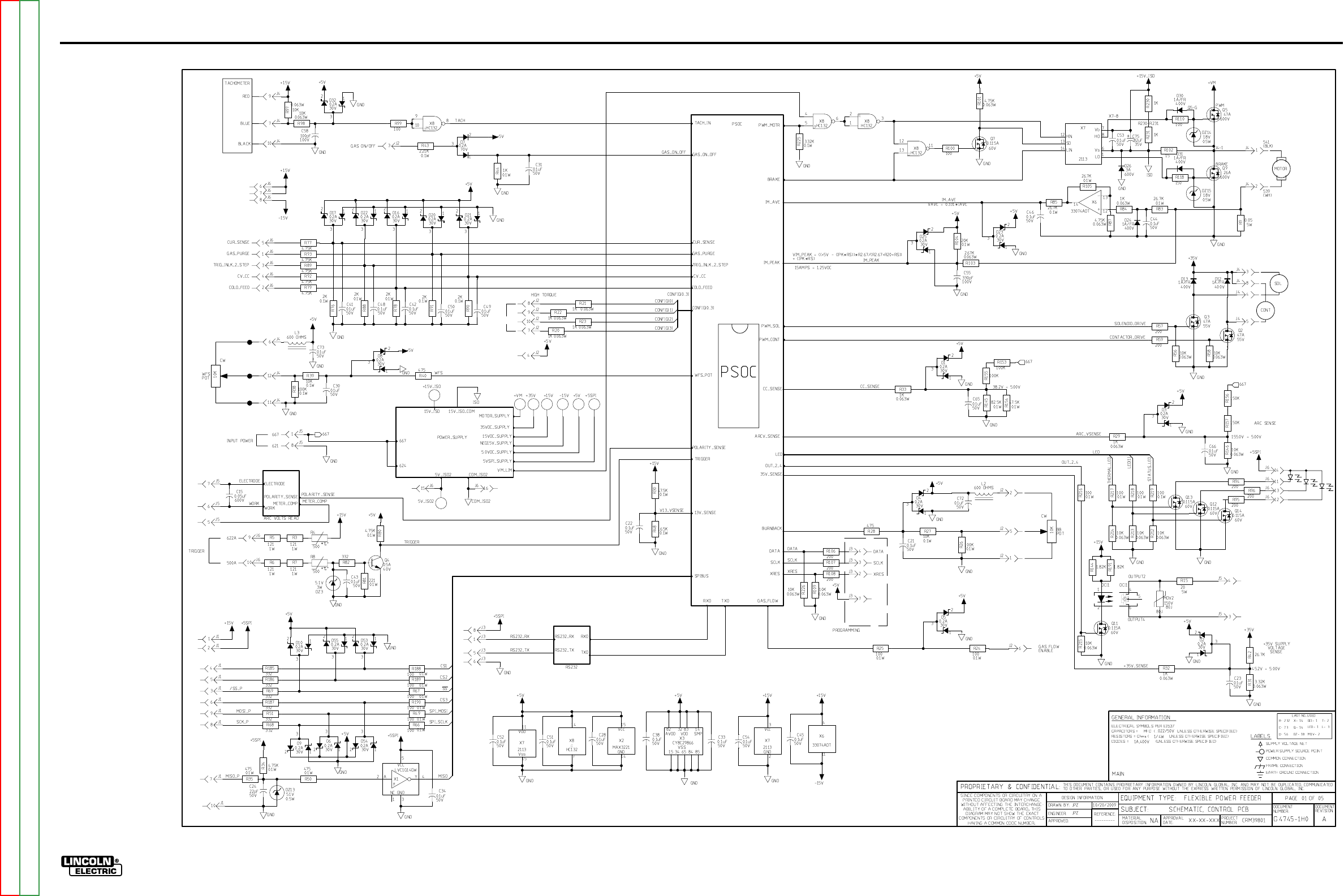
ElECTriCal DiaGrams G-14
lN-25™ prO
sChEmaTiC - lN-25 prO CONTrOl pC BOarD - CODEs 11387, 11388, 11507, 11508 (G4745-1) pG 1
G-14
NOTE: This diagram is for reference only. It may not be accurate for all machines covered by this manual.
Return to Section TOC Return to Section TOC Return to Section TOC Return to Section TOC
Return to Master TOC Return to Master TOC Return to Master TOC Return to Master TOC
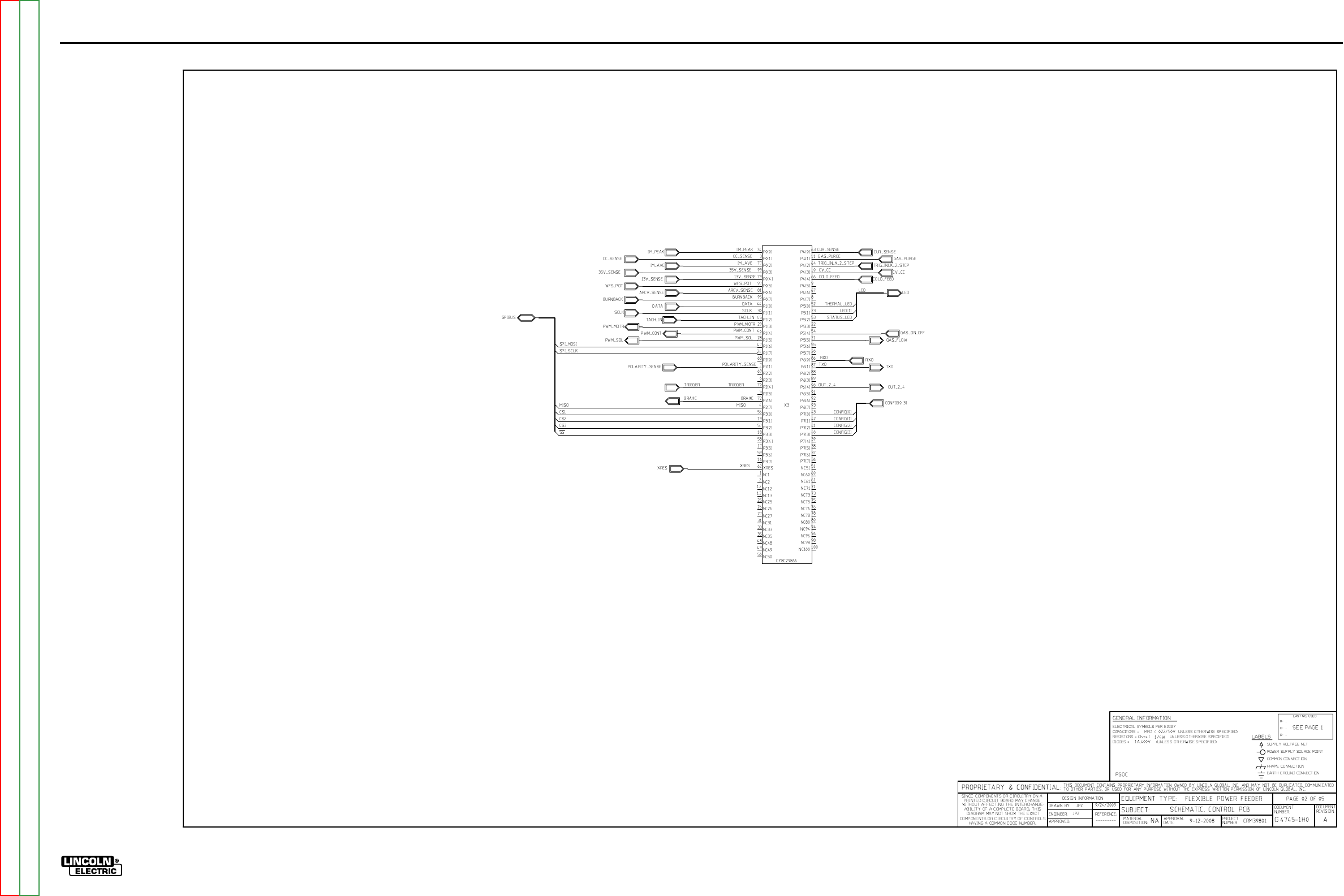
ElECTriCal DiaGrams G-15
lN-25™ prO
sChEmaTiC - lN-25 prO CONTrOl pC BOarD - CODEs 11387, 11388, 11507, 11508 (G4745-1) pG 2
G-15
NOTE: This diagram is for reference only. It may not be accurate for all machines covered by this manual.
Return to Section TOC Return to Section TOC Return to Section TOC Return to Section TOC
Return to Master TOC Return to Master TOC Return to Master TOC Return to Master TOC
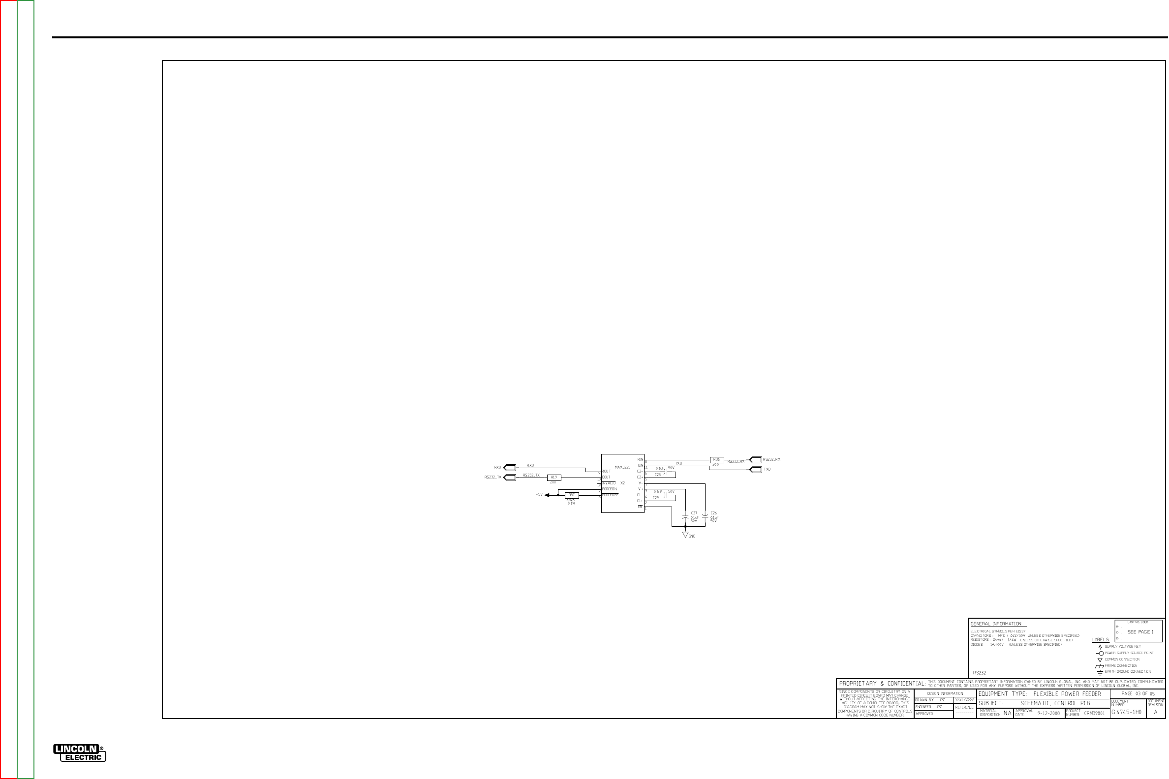
ElECTriCal DiaGrams G-16
lN-25™ prO
sChEmaTiC - lN-25 prO CONTrOl pC BOarD - CODEs 11387, 11388, 11507, 11508 (G4745-1) pG 3
G-16
NOTE: This diagram is for reference only. It may not be accurate for all machines covered by this manual.
Return to Section TOC Return to Section TOC Return to Section TOC Return to Section TOC
Return to Master TOC Return to Master TOC Return to Master TOC Return to Master TOC
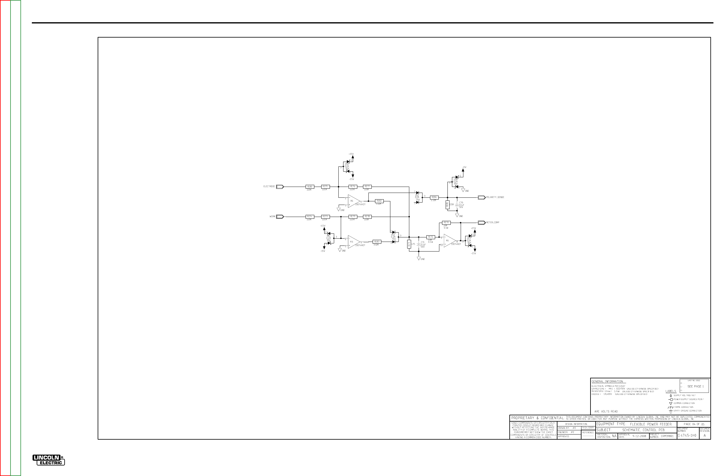
ElECTriCal DiaGrams G-17
lN-25™ prO
sChEmaTiC - lN-25 prO CONTrOl pC BOarD - CODEs 11387, 11388, 11507, 11508 (G4745-1) pG 4
G-17
NOTE: This diagram is for reference only. It may not be accurate for all machines covered by this manual.
Return to Section TOC Return to Section TOC Return to Section TOC Return to Section TOC
Return to Master TOC Return to Master TOC Return to Master TOC Return to Master TOC
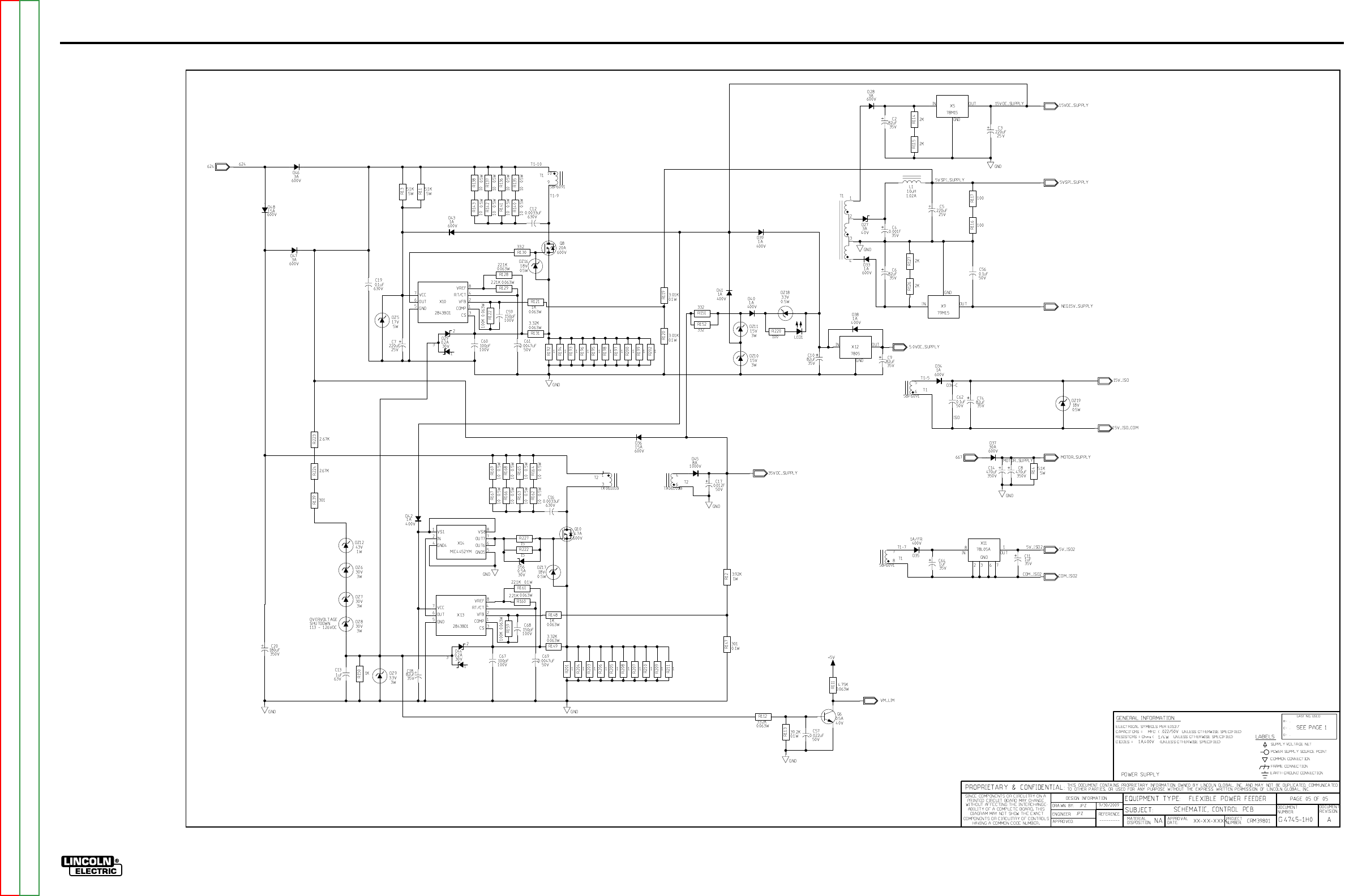
ElECTriCal DiaGrams G-18
lN-25™ prO
sChEmaTiC - lN-25 prO CONTrOl pC BOarD - CODEs 11387, 11388, 11507, 11508 (G4745-1) pG 5
G-18
NOTE: This diagram is for reference only. It may not be accurate for all machines covered by this manual.
Return to Section TOC Return to Section TOC Return to Section TOC Return to Section TOC
Return to Master TOC Return to Master TOC Return to Master TOC Return to Master TOC
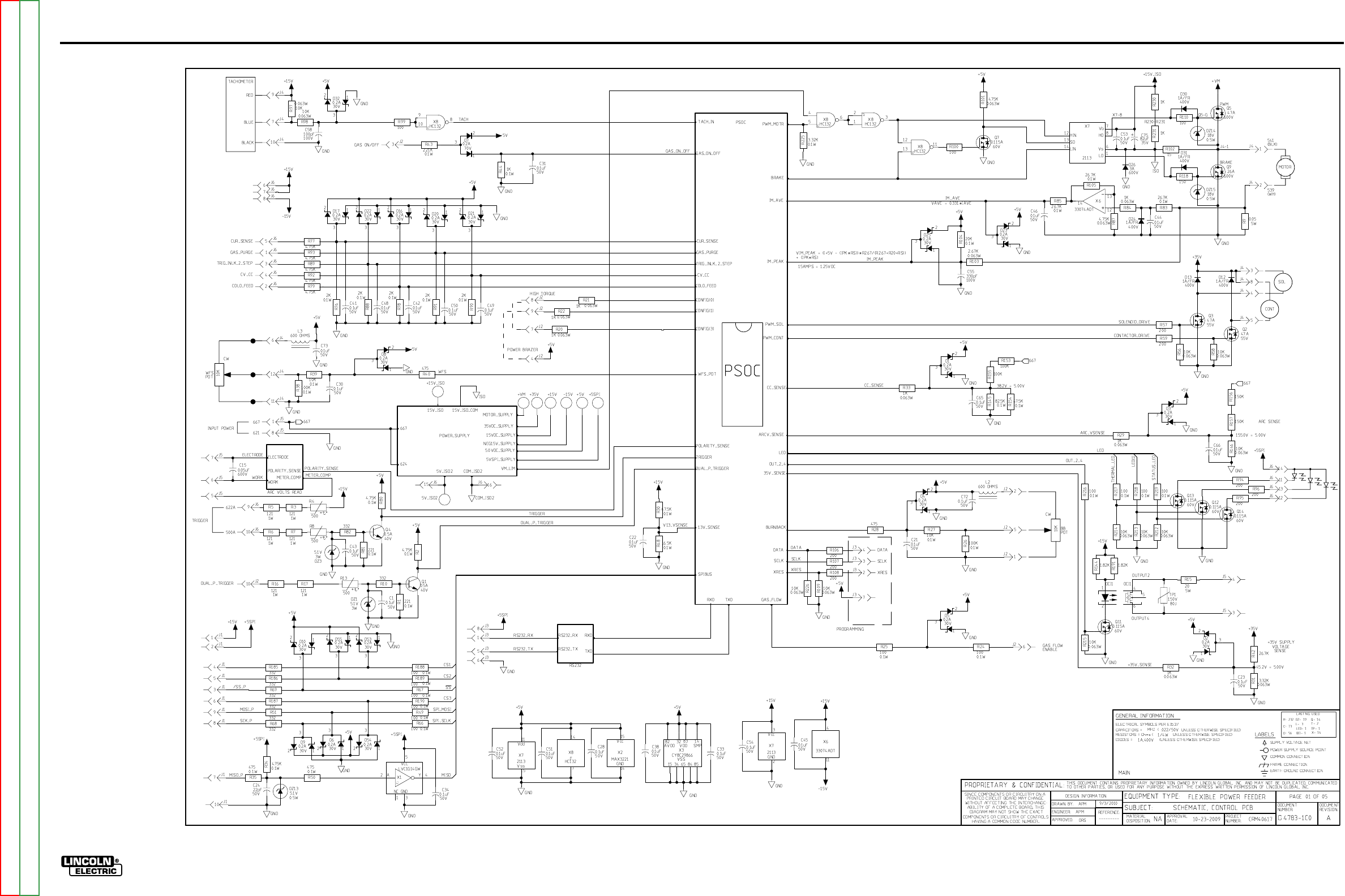
ElECTriCal DiaGrams G-19
lN-25™ prO
sChEmaTiC - lN-25 prO CONTrOl pC BOarD - CODEs 11620, 11621, 11716, 11717, 11746, 11747 (G4783-1) pG 1
G-19
NOTE: This diagram is for reference only. It may not be accurate for all machines covered by this manual.
Return to Section TOC Return to Section TOC Return to Section TOC Return to Section TOC
Return to Master TOC Return to Master TOC Return to Master TOC Return to Master TOC
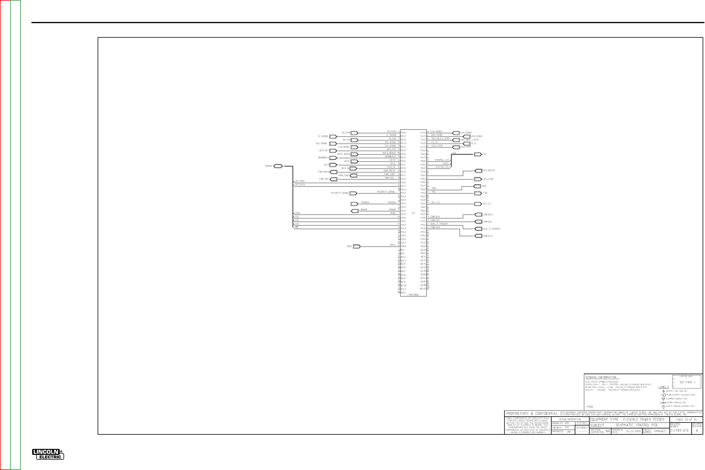
ElECTriCal DiaGrams G-20
lN-25™ prO
sChEmaTiC- lN-25 prO CONTrOl pC BOarD - CODEs 11620, 11621, 11716, 11717, 11746, 11747 (G4783-1) pG 2
G-20
NOTE: This diagram is for reference only. It may not be accurate for all machines covered by this manual.
Return to Section TOC Return to Section TOC Return to Section TOC Return to Section TOC
Return to Master TOC Return to Master TOC Return to Master TOC Return to Master TOC
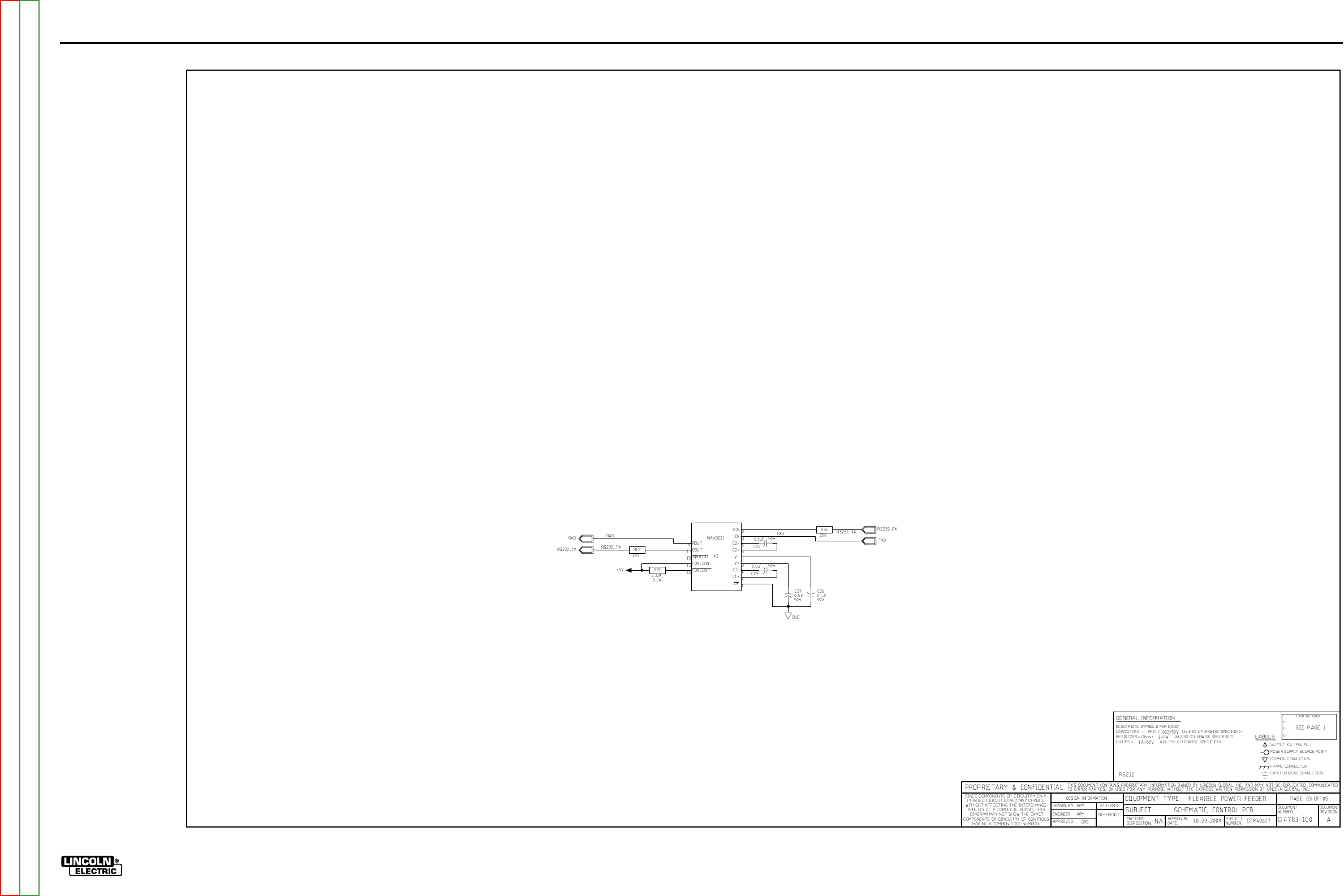
ElECTriCal DiaGrams G-21
lN-25™ prO
sChEmaTiC- lN-25 prO CONTrOl pC BOarD - CODEs 11620, 11621, 11716, 11717, 11746, 11747 (G4783-1) pG 3
G-21
NOTE: This diagram is for reference only. It may not be accurate for all machines covered by this manual.
Return to Section TOC Return to Section TOC Return to Section TOC Return to Section TOC
Return to Master TOC Return to Master TOC Return to Master TOC Return to Master TOC
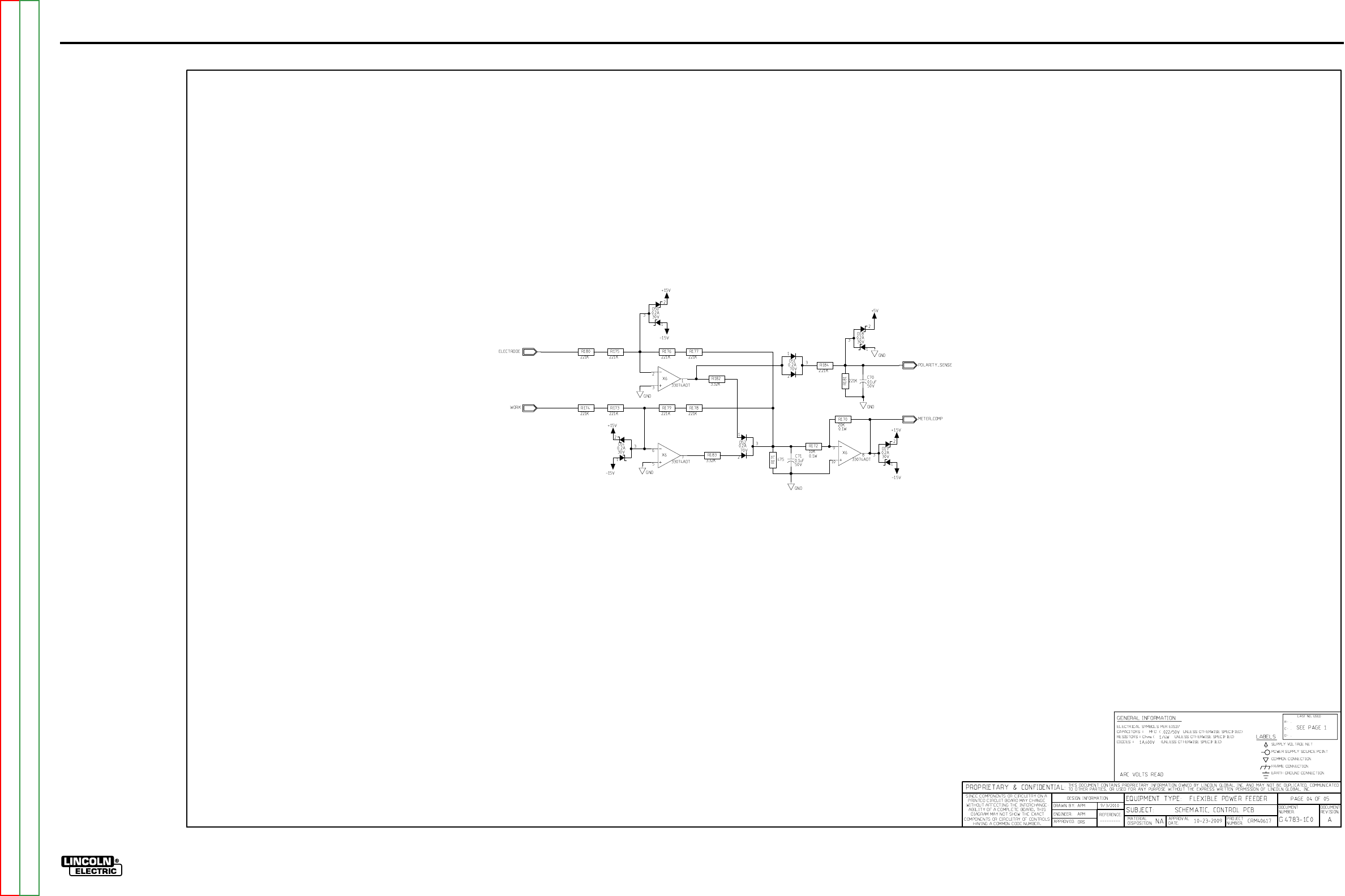
ElECTriCal DiaGrams G-22
lN-25™ prO
sChEmaTiC- lN-25 prO CONTrOl pC BOarD - CODEs 11620, 11621, 11716, 11717, 11746, 11747 (G4783-1) pG 4
G-22
NOTE: This diagram is for reference only. It may not be accurate for all machines covered by this manual.
Return to Section TOC Return to Section TOC Return to Section TOC Return to Section TOC
Return to Master TOC Return to Master TOC Return to Master TOC Return to Master TOC
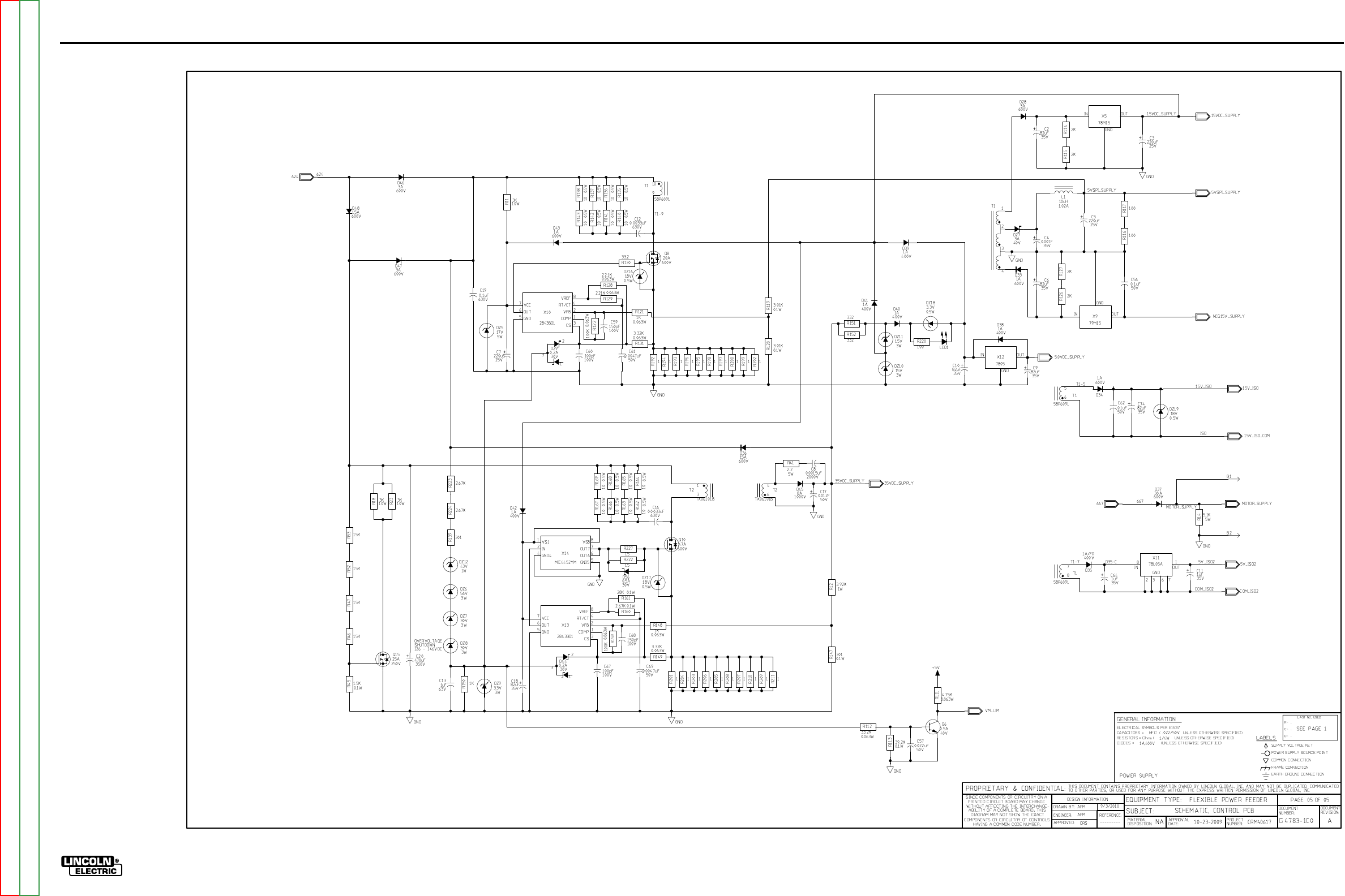
ElECTriCal DiaGrams G-23
lN-25™ prO
sChEmaTiC- lN-25 prO CONTrOl pC BOarD - CODEs 11620, 11621, 11716, 11717, 11746, 11747 (G4783-1) pG 5
G-23
NOTE: This diagram is for reference only. It may not be accurate for all machines covered by this manual.
Return to Section TOC Return to Section TOC Return to Section TOC Return to Section TOC
Return to Master TOC Return to Master TOC Return to Master TOC Return to Master TOC
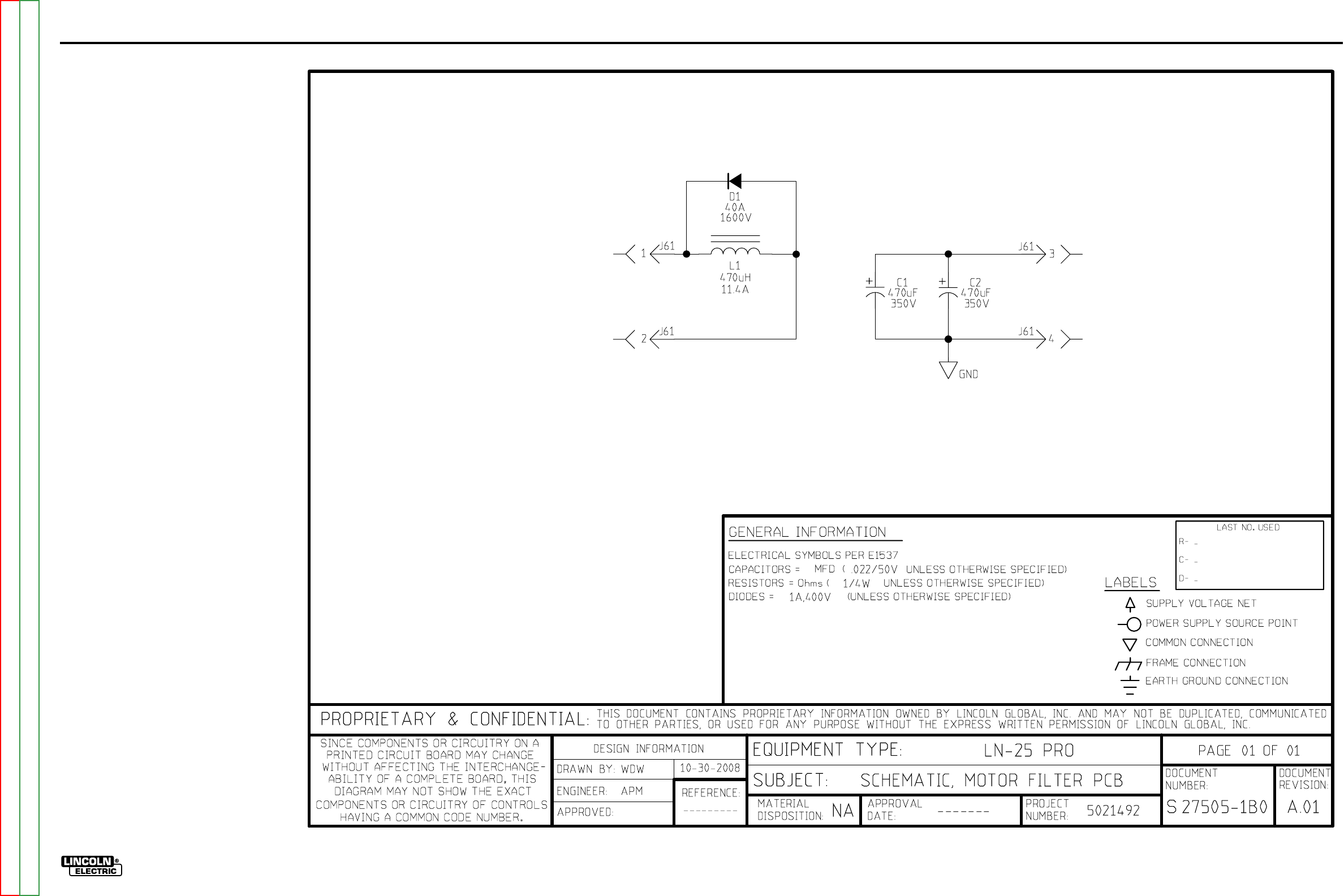
ElECTriCal DiaGrams G-24
lN-25™ prO
sChEmaTiC - mOTOr FilTEr pC BOarD - CODE 11746, 11747 (s27505-1)
G-24
NOTE: This diagram is for reference only. It may not be accurate for all machines covered by this manual.
Return to Section TOC Return to Section TOC Return to Section TOC Return to Section TOC
Return to Master TOC Return to Master TOC Return to Master TOC Return to Master TOC
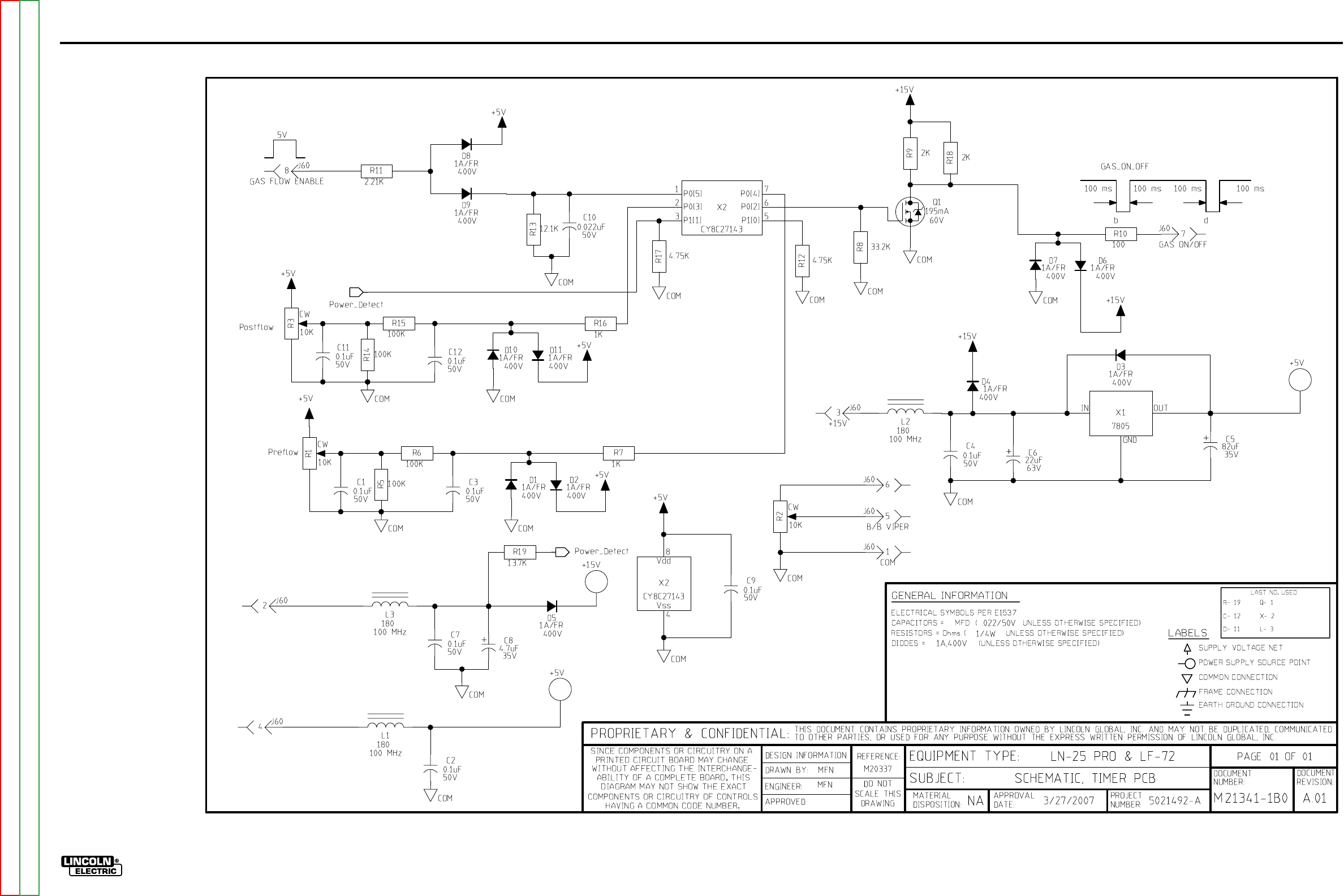
ElECTriCal DiaGrams G-25
lN-25™ prO
sChEmaTiC - K2330 TimEr KiT pC BOarD - all CODEs (m21341-1)
G-25
NOTE: This diagram is for reference only. It may not be accurate for all machines covered by this manual.
Return to Section TOC Return to Section TOC Return to Section TOC Return to Section TOC
Return to Master TOC Return to Master TOC Return to Master TOC Return to Master TOC
