Lincoln Electric Ln 8 Svm132 A Users Manual Svm132a
SVM132-A to the manual fc4a2110-b391-452e-97fe-4fe2779a7b57
2015-02-09
: Lincoln-Electric Lincoln-Electric-Ln-8-Svm132-A-Users-Manual-574292 lincoln-electric-ln-8-svm132-a-users-manual-574292 lincoln-electric pdf
Open the PDF directly: View PDF ![]() .
.
Page Count: 99
- Master Table of Contents
- Safety
- Section A - Installation
- Section B - Operation
- Section C - Accessories
- Section D - Maintenance
- Section E - Theory of Operation
- Section F - Troubleshooting and Repair
- Symptoms
- No wire feed or arc voltage when the gun trigger is activated. The drive rolls do not turn. The LN-8 appears “dead”.
- The wire feeds when the gun trigger is activated but there is no arc voltage.
- The wire continues to feed with the gun trigger open, and the wire is electrically “hot”. The interlock switch is in the “off” position.
- With the interlock switch (S2) in the “ON” postion, the wire feed stops when the gun trigger is released.
- The circuit breaker (5 amp) repeatedly trips when the gun trigger is activated.
- The circuit breaker (5 amp) trips when power is applied to the LN-8. Gun trigger is NOT activated.
- The 1/2 amp fuse on the relay board repeatedly fails.
- The drive motor thermostat “opens” while welding.
- The wire feed speed cannot be controlled. The motor runs and feeds wire but the speed cannot be changed regardless of control setting.
- The wire feed “coasts” when the gun trigger is released.
- The wire feeds normally and welds but the solenoid is not operating.
- When the gun trigger is activated the wire “backs up” instead of feeding forward.
- When the gun trigger is activated, the drive rolls turn but the wire will not feed or wire feeding is rough.
- The welding arc is variable or “hunting”.
- Poor arc striking with sticking or “blast offs”. The weld bead may also be ropey and display weld porosity.
- Section G - Electrical Diagrams
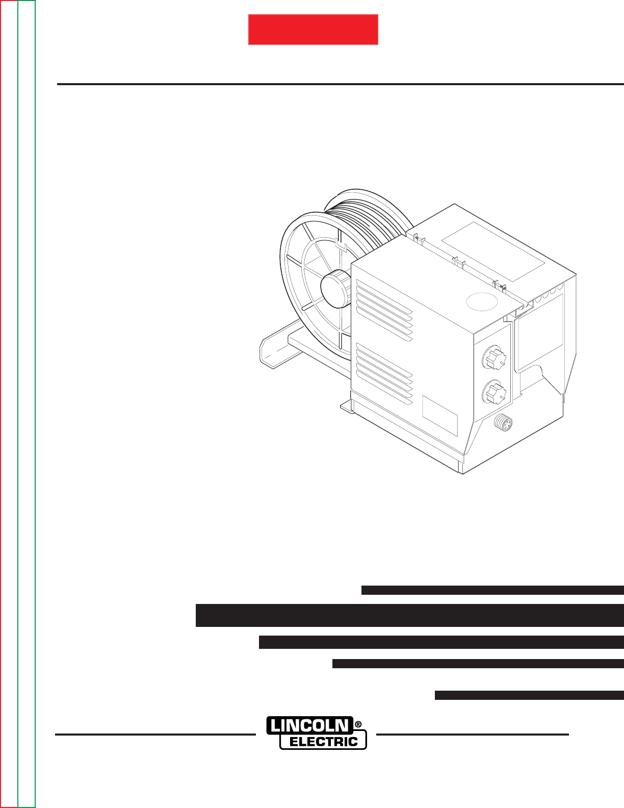
LN-8 SEMIAUTOMATIC WIRE FEEDER
SERVICE MANUAL
SVM132-A
May, 2002
Safety Depends on You
Lincoln arc welding and cutting
equipment is designed and built
with safety in mind. However, your
overall safety can be increased by
proper installation ... and thought-
ful operation on your part. DO
NOT INSTALL, OPERATE OR
REPAIR THIS EQUIPMENT
WITHOUT READING THIS
MANUAL AND THE SAFETY
PRECAUTIONS CONTAINED
THROUGHOUT. And, most
importantly, think before you act
and be careful.
For use with code numbers: 9963, 9964
Return to Master TOC Return to Master TOC Return to Master TOC Return to Master TOC
View Safety Info View Safety Info View Safety Info View Safety Info
• Sales and Service through Subsidiaries and Distributors Worldwide •
Cleveland, Ohio 44117-1199 U.S.A. TEL: 216.481.8100 FAX: 216.486.1751 WEB SITE: www.lincolnelectric.com
• World's Leader in Welding and Cutting Products •
Copyright © 2002 Lincoln Global Inc.
RETURN TO MAIN INDEX
Return to Master TOC Return to Master TOC Return to Master TOC Return to Master TOC
LN-8
SAFETY
FOR ENGINE
powered equipment.
1.a. Turn the engine off before troubleshooting and maintenance
work unless the maintenance work requires it to be running.
____________________________________________________
1.b.Operate engines in open, well-ventilated
areas or vent the engine exhaust fumes
outdoors.
____________________________________________________
1.c. Do not add the fuel near an open flame
welding arc or when the engine is running.
Stop the engine and allow it to cool before
refueling to prevent spilled fuel from vaporiz-
ing on contact with hot engine parts and
igniting. Do not spill fuel when filling tank. If
fuel is spilled, wipe it up and do not start
engine until fumes have been eliminated.
____________________________________________________
1.d. Keep all equipment safety guards, covers
and devices in position and in good
repair.Keep hands, hair, clothing and tools
away from V-belts, gears, fans and all other
moving parts when starting, operating or
repairing equipment.
____________________________________________________
1.e. In some cases it may be necessary to remove safety
guards to perform required maintenance. Remove
guards only when necessary and replace them when the
maintenance requiring their removal is complete.
Always use the greatest care when working near moving
parts.
___________________________________________________
1.f. Do not put your hands near the engine fan. Do not attempt
to override the governor or idler by pushing on the throttle
control rods while the engine is running.
___________________________________________________
1.g. To prevent accidentally starting gasoline engines while
turning the engine or welding generator during maintenance
work, disconnect the spark plug wires, distributor cap or
magneto wire as appropriate.
ii
ARC WELDING CAN BE HAZARDOUS. PROTECT YOURSELF AND OTHERS FROM POSSIBLE SERIOUS INJURY OR DEATH.
KEEP CHILDREN AWAY. PACEMAKER WEARERS SHOULD CONSULT WITH THEIR DOCTOR BEFORE OPERATING.
Read and understand the following safety highlights. For additional safety information, it is strongly recommended that you
purchase a copy of “Safety in Welding & Cutting - ANSI Standard Z49.1” from the American Welding Society, P.O. Box
351040, Miami, Florida 33135 or CSA Standard W117.2-1974. A Free copy of “Arc Welding Safety” booklet E205 is available
from the Lincoln Electric Company, 22801 St. Clair Avenue, Cleveland, Ohio 44117-1199.
BE SURE THAT ALL INSTALLATION, OPERATION, MAINTENANCE AND REPAIR PROCEDURES ARE
PERFORMED ONLY BY QUALIFIED INDIVIDUALS.
WARNING
Mar ‘95
ELECTRIC AND
MAGNETIC FIELDS
may be dangerous
2.a. Electric current flowing through any conductor causes
localized Electric and Magnetic Fields (EMF). Welding
current creates EMF fields around welding cables and
welding machines
2.b. EMF fields may interfere with some pacemakers, and
welders having a pacemaker should consult their physician
before welding.
2.c. Exposure to EMF fields in welding may have other health
effects which are now not known.
2.d. All welders should use the following procedures in order to
minimize exposure to EMF fields from the welding circuit:
2.d.1.
Route the electrode and work cables together - Secure
them with tape when possible.
2.d.2. Never coil the electrode lead around your body.
2.d.3. Do not place your body between the electrode and
work cables. If the electrode cable is on your right
side, the work cable should also be on your right side.
2.d.4. Connect the work cable to the workpiece as close as
possible to the area being welded.
2.d.5. Do not work next to welding power source.
1.h. To avoid scalding, do not remove the
radiator pressure cap when the engine is
hot.
CALIFORNIA PROPOSITION 65 WARNINGS
Diesel engine exhaust and some of its constituents
are known to the State of California to cause can-
cer, birth defects, and other reproductive harm.
The engine exhaust from this product contains
chemicals known to the State of California to cause
cancer, birth defects, or other reproductive harm.
The Above For Diesel Engines The Above For Gasoline Engines
Return to Master TOC Return to Master TOC Return to Master TOC Return to Master TOC
LN-8
SAFETY iiii
ARC RAYS can burn.
4.a. Use a shield with the proper filter and cover
plates to protect your eyes from sparks and
the rays of the arc when welding or observing
open arc welding. Headshield and filter lens
should conform to ANSI Z87. I standards.
4.b. Use suitable clothing made from durable flame-resistant
material to protect your skin and that of your helpers from
the arc rays.
4.c. Protect other nearby personnel with suitable, non-flammable
screening and/or warn them not to watch the arc nor expose
themselves to the arc rays or to hot spatter or metal.
ELECTRIC SHOCK can
kill.
3.a. The electrode and work (or ground) circuits
are electrically “hot” when the welder is on.
Do not touch these “hot” parts with your bare
skin or wet clothing. Wear dry, hole-free
gloves to insulate hands.
3.b. Insulate yourself from work and ground using dry insulation.
Make certain the insulation is large enough to cover your full
area of physical contact with work and ground.
In addition to the normal safety precautions, if welding
must be performed under electrically hazardous
conditions (in damp locations or while wearing wet
clothing; on metal structures such as floors, gratings or
scaffolds; when in cramped positions such as sitting,
kneeling or lying, if there is a high risk of unavoidable or
accidental contact with the workpiece or ground) use
the following equipment:
• Semiautomatic DC Constant Voltage (Wire) Welder.
• DC Manual (Stick) Welder.
• AC Welder with Reduced Voltage Control.
3.c. In semiautomatic or automatic wire welding, the electrode,
electrode reel, welding head, nozzle or semiautomatic
welding gun are also electrically “hot”.
3.d. Always be sure the work cable makes a good electrical
connection with the metal being welded. The connection
should be as close as possible to the area being welded.
3.e. Ground the work or metal to be welded to a good electrical
(earth) ground.
3.f.
Maintain the electrode holder, work clamp, welding cable and
welding machine in good, safe operating condition. Replace
damaged insulation.
3.g. Never dip the electrode in water for cooling.
3.h. Never simultaneously touch electrically “hot” parts of
electrode holders connected to two welders because voltage
between the two can be the total of the open circuit voltage
of both welders.
3.i. When working above floor level, use a safety belt to protect
yourself from a fall should you get a shock.
3.j. Also see Items 6.c. and 8.
FUMES AND GASES
can be dangerous.
5.a. Welding may produce fumes and gases
hazardous to health. Avoid breathing these
fumes and gases.When welding, keep
your head out of the fume. Use enough
ventilation and/or exhaust at the arc to keep
fumes and gases away from the breathing zone. When
welding with electrodes which require special
ventilation such as stainless or hard facing (see
instructions on container or MSDS) or on lead or
cadmium plated steel and other metals or coatings
which produce highly toxic fumes, keep exposure as
low as possible and below Threshold Limit Values (TLV)
using local exhaust or mechanical ventilation. In
confined spaces or in some circumstances, outdoors, a
respirator may be required. Additional precautions are
also required when welding on galvanized steel.
5.b.
Do not weld in locations near chlorinated hydrocarbon
vapors
coming from degreasing, cleaning or spraying operations.
The heat and rays of the arc can react with solvent vapors
to
form phosgene, a highly toxic gas, and other irritating
products.
5.c. Shielding gases used for arc welding can displace air and
cause injury or death. Always use enough ventilation,
especially in confined areas, to insure breathing air is safe.
5.d. Read and understand the manufacturer’s instructions for this
equipment and the consumables to be used, including the
material safety data sheet (MSDS) and follow your
employer’s safety practices. MSDS forms are available from
your welding distributor or from the manufacturer.
5.e. Also see item 1.b. Mar ‘95
Return to Master TOC Return to Master TOC Return to Master TOC Return to Master TOC
LN-8
SAFETY
FOR ELECTRICALLY
powered equipment.
8.a. Turn off input power using the disconnect
switch at the fuse box before working on
the equipment.
8.b. Install equipment in accordance with the U.S. National
Electrical Code, all local codes and the manufacturer’s
recommendations.
8.c. Ground the equipment in accordance with the U.S. National
Electrical Code and the manufacturer’s recommendations.
CYLINDER may explode
if damaged.
7.a. Use only compressed gas cylinders
containing the correct shielding gas for the
process used and properly operating
regulators designed for the gas and
pressure used. All hoses, fittings, etc. should be suitable for
the application and maintained in good condition.
7.b. Always keep cylinders in an upright position securely
chained to an undercarriage or fixed support.
7.c. Cylinders should be located:
•Away from areas where they may be struck or subjected to
physical damage.
•A safe distance from arc welding or cutting operations and
any other source of heat, sparks, or flame.
7.d. Never allow the electrode, electrode holder or any other
electrically “hot” parts to touch a cylinder.
7.e. Keep your head and face away from the cylinder valve outlet
when opening the cylinder valve.
7.f. Valve protection caps should always be in place and hand
tight except when the cylinder is in use or connected for
use.
7.g. Read and follow the instructions on compressed gas
cylinders, associated equipment, and CGA publication P-l,
“Precautions for Safe Handling of Compressed Gases in
Cylinders,” available from the Compressed Gas Association
1235 Jefferson Davis Highway, Arlington, VA 22202.
iiiiii
Mar ‘95
WELDING SPARKS can
cause fire or explosion.
6.a.
Remove fire hazards from the welding area.
If this is not possible, cover them to prevent
the welding sparks from starting a fire.
Remember that welding sparks and hot
materials from welding can easily go through small cracks
and openings to adjacent areas. Avoid welding near
hydraulic lines. Have a fire extinguisher readily available.
6.b. Where compressed gases are to be used at the job site,
special precautions should be used to prevent hazardous
situations. Refer to “Safety in Welding and Cutting” (ANSI
Standard Z49.1) and the operating information for the
equipment being used.
6.c. When not welding, make certain no part of the electrode
circuit is touching the work or ground. Accidental contact
can cause overheating and create a fire hazard.
6.d. Do not heat, cut or weld tanks, drums or containers until the
proper steps have been taken to insure that such procedures
will not cause flammable or toxic vapors from substances
inside. They can cause an explosion even
though
they have
been “cleaned”. For information, purchase “Recommended
Safe Practices for the
Preparation
for Welding and Cutting of
Containers and Piping That Have Held Hazardous
Substances”, AWS F4.1 from the American Welding Society
(see address above).
6.e. Vent hollow castings or containers before heating, cutting or
welding. They may explode.
6.f.
Sparks and spatter are thrown from the welding arc. Wear oil
free protective garments such as leather gloves, heavy shirt,
cuffless trousers, high shoes and a cap over your hair. Wear
ear plugs when welding out of position or in confined places.
Always wear safety glasses with side shields when in a
welding area.
6.g. Connect the work cable to the work as close to the welding
area as practical. Work cables connected to the building
framework or other locations away from the welding area
increase the possibility of the welding current passing
through lifting chains, crane cables or other alternate cir-
cuits. This can create fire hazards or overheat lifting chains
or cables until they fail.
6.h. Also see item 1.c.

Return to Master TOC Return to Master TOC Return to Master TOC Return to Master TOC
LN-8
iv
SAFETY
iv
PRÉCAUTIONS DE SÛRETÉ
Pour votre propre protection lire et observer toutes les instruc-
tions et les précautions de sûreté specifiques qui parraissent
dans ce manuel aussi bien que les précautions de sûreté
générales suivantes:
Sûreté Pour Soudage A L’Arc
1. Protegez-vous contre la secousse électrique:
a. Les circuits à l’électrode et à la piéce sont sous tension
quand la machine à souder est en marche. Eviter toujours
tout contact entre les parties sous tension et la peau nue
ou les vétements mouillés. Porter des gants secs et sans
trous pour isoler les mains.
b. Faire trés attention de bien s’isoler de la masse quand on
soude dans des endroits humides, ou sur un plancher
metallique ou des grilles metalliques, principalement dans
les positions assis ou couché pour lesquelles une grande
partie du corps peut être en contact avec la masse.
c. Maintenir le porte-électrode, la pince de masse, le câble
de soudage et la machine à souder en bon et sûr état
defonctionnement.
d.Ne jamais plonger le porte-électrode dans l’eau pour le
refroidir.
e. Ne jamais toucher simultanément les parties sous tension
des porte-électrodes connectés à deux machines à soud-
er parce que la tension entre les deux pinces peut être le
total de la tension à vide des deux machines.
f. Si on utilise la machine à souder comme une source de
courant pour soudage semi-automatique, ces precautions
pour le porte-électrode s’applicuent aussi au pistolet de
soudage.
2. Dans le cas de travail au dessus du niveau du sol, se pro-
téger contre les chutes dans le cas ou on recoit un choc. Ne
jamais enrouler le câble-électrode autour de n’importe quelle
partie du corps.
3. Un coup d’arc peut être plus sévère qu’un coup de soliel,
donc:
a. Utiliser un bon masque avec un verre filtrant approprié
ainsi qu’un verre blanc afin de se protéger les yeux du
rayonnement de l’arc et des projections quand on soude
ou quand on regarde l’arc.
b. Porter des vêtements convenables afin de protéger la
peau de soudeur et des aides contre le rayonnement de
l‘arc.
c. Protéger l’autre personnel travaillant à proximité au
soudage à l’aide d’écrans appropriés et non-inflamma-
bles.
4. Des gouttes de laitier en fusion sont émises de l’arc de
soudage. Se protéger avec des vêtements de protection
libres de l’huile, tels que les gants en cuir, chemise épaisse,
pantalons sans revers, et chaussures montantes.
5. Toujours porter des lunettes de sécurité dans la zone de
soudage. Utiliser des lunettes avec écrans lateraux dans les
zones où l’on pique le laitier.
6. Eloigner les matériaux inflammables ou les recouvrir afin de
prévenir tout risque d’incendie dû aux étincelles.
7. Quand on ne soude pas, poser la pince à une endroit isolé de
la masse. Un court-circuit accidental peut provoquer un
échauffement et un risque d’incendie.
8. S’assurer que la masse est connectée le plus prés possible
de la zone de travail qu’il est pratique de le faire. Si on place
la masse sur la charpente de la construction ou d’autres
endroits éloignés de la zone de travail, on augmente le risque
de voir passer le courant de soudage par les chaines de lev-
age, câbles de grue, ou autres circuits. Cela peut provoquer
des risques d’incendie ou d’echauffement des chaines et des
câbles jusqu’à ce qu’ils se rompent.
9. Assurer une ventilation suffisante dans la zone de soudage.
Ceci est particuliérement important pour le soudage de tôles
galvanisées plombées, ou cadmiées ou tout autre métal qui
produit des fumeés toxiques.
10. Ne pas souder en présence de vapeurs de chlore provenant
d’opérations de dégraissage, nettoyage ou pistolage. La
chaleur ou les rayons de l’arc peuvent réagir avec les
vapeurs du solvant pour produire du phosgéne (gas forte-
ment toxique) ou autres produits irritants.
11. Pour obtenir de plus amples renseignements sur la sûreté,
voir le code “Code for safety in welding and cutting” CSA
Standard W 117.2-1974.
PRÉCAUTIONS DE SÛRETÉ POUR
LES MACHINES À SOUDER À
TRANSFORMATEUR ET À
REDRESSEUR
1. Relier à la terre le chassis du poste conformement au code
de l’électricité et aux recommendations du fabricant. Le dis-
positif de montage ou la piece à souder doit être branché à
une bonne mise à la terre.
2. Autant que possible, I’installation et l’entretien du poste
seront effectués par un électricien qualifié.
3. Avant de faires des travaux à l’interieur de poste, la
debrancher à l’interrupteur à la boite de fusibles.
4. Garder tous les couvercles et dispositifs de sûreté à leur
place.
Mar. ‘93

LN-8
MASTER TABLE OF CONTENTS FOR ALL SECTIONS
Page
Safety . . . . . . . . . . . . . . . . . . . . . . . . . . . . . . . . . . . . . . . . . . . . . . . . . . . . . . . i-iv
Installation . . . . . . . . . . . . . . . . . . . . . . . . . . . . . . . . . . . . . . . . . . . . . . . . . . . . Section A
Technical Specifications - LN-8 . . . . . . . . . . . . . . . . . . . . . . . . . . . . . . . . . A-2
Mounting Location . . . . . . . . . . . . . . . . . . . . . . . . . . . . . . . . . . . . . . . . . . . A-3
Power Source Connections . . . . . . . . . . . . . . . . . . . . . . . . . . . . . . . . . . . . A-3
Power Source Connection Diagrams . . . . . . . . . . . . . . . . . . . . . . . . . . . . . A-5
Gun and Cable Assemblies . . . . . . . . . . . . . . . . . . . . . . . . . . . . . . . . . . . . A-18
LN-8S and LN-8SE Continuous Flux Feed (Submerged Arc) . . . . . . . . . . A-18
Operation . . . . . . . . . . . . . . . . . . . . . . . . . . . . . . . . . . . . . . . . . . . . . . . . . . . . . Section B
Safety Instructions . . . . . . . . . . . . . . . . . . . . . . . . . . . . . . . . . . . . . . . . . . . B-2
Controls and Their Functions . . . . . . . . . . . . . . . . . . . . . . . . . . . . . . . . . . . B-2
Circuit Protection . . . . . . . . . . . . . . . . . . . . . . . . . . . . . . . . . . . . . . . . . . . . B-4
Avoiding Ground Lead Protector (GLP) Activation . . . . . . . . . . . . . . . . . . B-4
Wire Feed Rolls and Guide Tubes . . . . . . . . . . . . . . . . . . . . . . . . . . . . . . . B-5
Setting for CV or CC Power Sources . . . . . . . . . . . . . . . . . . . . . . . . . . . . . B-6
Welding with a Constant Voltage Power Source . . . . . . . . . . . . . . . . . . . . B-7
Welding with a Constant Current Power Source . . . . . . . . . . . . . . . . . . . . B-7
Wire Reel Loading - 50 and 60 lb. Coils (K303 Wire Reel Stand) . . . . . . . B-8
Wire Reel Loading (K1524-1 Unversal Wire Reel Stand) . . . . . . . . . . . . . . B-9
Slow Acceleration Starting (Code 7926 and Above) . . . . . . . . . . . . . . . . . B-12
Flux Tank Loading . . . . . . . . . . . . . . . . . . . . . . . . . . . . . . . . . . . . . . . . . . . B-12
Accessories . . . . . . . . . . . . . . . . . . . . . . . . . . . . . . . . . . . . . . . . . . . . . . . . . . . Section C
General . . . . . . . . . . . . . . . . . . . . . . . . . . . . . . . . . . . . . . . . . . . . . . . . . . . . C-2
Reel Mounting Accessories . . . . . . . . . . . . . . . . . . . . . . . . . . . . . . . . . . . . C-4
Welding Guns . . . . . . . . . . . . . . . . . . . . . . . . . . . . . . . . . . . . . . . . . . . . . . . C-5
Welding Gun Accessories . . . . . . . . . . . . . . . . . . . . . . . . . . . . . . . . . . . . . C-5
Constant Current Conversion Parts . . . . . . . . . . . . . . . . . . . . . . . . . . . . . . C-5
Maintenance . . . . . . . . . . . . . . . . . . . . . . . . . . . . . . . . . . . . . . . . . . . . . . . . . . Section D
Routine Maintenance . . . . . . . . . . . . . . . . . . . . . . . . . . . . . . . . . . . . . . . . . D-2
Periodic Maintenance . . . . . . . . . . . . . . . . . . . . . . . . . . . . . . . . . . . . . . . . D-2
Theory of Operation . . . . . . . . . . . . . . . . . . . . . . . . . . . . . . . . . . . . . . . . . . . . Section E
General Description . . . . . . . . . . . . . . . . . . . . . . . . . . . . . . . . . . . . . . . . . . E-2
Power Input Circuits . . . . . . . . . . . . . . . . . . . . . . . . . . . . . . . . . . . . . . . . . E-2
Gun Trigger and 1CR Relay Contact Control Circuits . . . . . . . . . . . . . . . . E-3
Variable Voltage Board, Meter Shunt, Wire Speed
and Remote Output Controls . . . . . . . . . . . . . . . . . . . . . . . . . . . . . . . E-4
SCR Operation . . . . . . . . . . . . . . . . . . . . . . . . . . . . . . . . . . . . . . . . . . . . . . E-5
Troubleshooting and Repair . . . . . . . . . . . . . . . . . . . . . . . . . . . . . . . . . . . . . Section F
How to Use Troubleshooting Guide . . . . . . . . . . . . . . . . . . . . . . . . . . . . . F-2
PC Board Troubleshooting Procedures . . . . . . . . . . . . . . . . . . . . . . . . . . . F-3
Troubleshooting Guide . . . . . . . . . . . . . . . . . . . . . . . . . . . . . . . . . . . . . . . F-4
LN-8 Electrical Sequence of Operation . . . . . . . . . . . . . . . . . . . . . . . . . . . F-10
Test Procedures . . . . . . . . . . . . . . . . . . . . . . . . . . . . . . . . . . . . . . . . . . . . . F-12
Component Replacement Procedures . . . . . . . . . . . . . . . . . . . . . . . . . . . F-24
Retest After Repair . . . . . . . . . . . . . . . . . . . . . . . . . . . . . . . . . . . . . . . . . . . F-40
Electrical Diagrams . . . . . . . . . . . . . . . . . . . . . . . . . . . . . . . . . . . . . . . . . . . . Section G
Parts Manual . . . . . . . . . . . . . . . . . . . . . . . . . . . . . . . . . . . . . . . . . . . . . . . . . P293 Series
vv RETURN TO MAIN INDEX

Return to Master TOC Return to Master TOC Return to Master TOC Return to Master TOC
SECTION A-1
INSTALLATION
LN-8
SECTION A-1
TABLE OF CONTENTS
-INSTALLATION SECTION-
Installation . . . . . . . . . . . . . . . . . . . . . . . . . . . . . . . . . . . . . . . . . . . . . . . . . . . . . . . . . . . . . . . Section A
Technical Specifications - LN-8 . . . . . . . . . . . . . . . . . . . . . . . . . . . . . . . . . . . . . . . . . . . . . A-2
Mounting Location . . . . . . . . . . . . . . . . . . . . . . . . . . . . . . . . . . . . . . . . . . . . . . . . . . . . . . . A-3
Power Source Connections . . . . . . . . . . . . . . . . . . . . . . . . . . . . . . . . . . . . . . . . . . . . . . . . A-3
LN-8N and LN-8NE . . . . . . . . . . . . . . . . . . . . . . . . . . . . . . . . . . . . . . . . . . . . . . . . . . . A-3
LN-8S and LN-8SE (and converted LN-8N and LN-8NE) . . . . . . . . . . . . . . . . . . . . . . A-4
Power Source Connection Diagrams . . . . . . . . . . . . . . . . . . . . . . . . . . . . . . . . . . . . . . . . . A-5
Connection of the LN-8 to an Idealarc R3S-400, 600 or 800
(with LVC) (Discontinued) . . . . . . . . . . . . . . . . . . . . . . . . . . . . . . . . . . . . . . . . . . . . A-6
Connection of LN-8 to an Idealarc R3S-400, 600 or 800
(without LVC) (Discontinued) . . . . . . . . . . . . . . . . . . . . . . . . . . . . . . . . . . . . . . . . . . A-7
Connection of LN-8 to a Sam Motor-Generator or Engine Driven Welder. . . . . . . . . . A-8
Connection of LN-8 to R3S-250 and R3S-325 . . . . . . . . . . . . . . . . . . . . . . . . . . . . . . A-9
Connection of LN-8 to DC-600 . . . . . . . . . . . . . . . . . . . . . . . . . . . . . . . . . . . . . . . . . . A-10
Connection of LN-8 to DC-250, 400 and CV/CVI Power Sources . . . . . . . . . . . . . . . . A-11
K318 Dual Process Contactor Kit DC-400, CV-400 and CVI-500 Connection
to LN-8 for Same Polarity Operation . . . . . . . . . . . . . . . . . . . . . . . . . . . . . . . . . . . . A-12
K318 Dual Process Contactor Kit DC-400, CV-400 and CVI-500 Connection
to LN-8 for Opposite Polarity Operation . . . . . . . . . . . . . . . . . . . . . . . . . . . . . . . . . A-13
For Power Sources Other Than Lincoln Electric . . . . . . . . . . . . . . . . . . . . . . . . . . . . . A-14
Input Cable Connections . . . . . . . . . . . . . . . . . . . . . . . . . . . . . . . . . . . . . . . . . . . . . . . A-15
LN-8N and LN-8S. . . . . . . . . . . . . . . . . . . . . . . . . . . . . . . . . . . . . . . . . . . . . . . . . . . . . A-15
LN-8NE and LN-8SE . . . . . . . . . . . . . . . . . . . . . . . . . . . . . . . . . . . . . . . . . . . . . . . . . . A-15
Gun and Cable Assemblies . . . . . . . . . . . . . . . . . . . . . . . . . . . . . . . . . . . . . . . . . . . . . . . . A-18
General . . . . . . . . . . . . . . . . . . . . . . . . . . . . . . . . . . . . . . . . . . . . . . . . . . . . . . . . . . . . . A-18
Gun Cable Connections . . . . . . . . . . . . . . . . . . . . . . . . . . . . . . . . . . . . . . . . . . . . . . . . A-18
Handling Procedures . . . . . . . . . . . . . . . . . . . . . . . . . . . . . . . . . . . . . . . . . . . . . . . . . . A-18
LN-8S and LN-8SE Continuous Flux Feed (Submerged Arc) . . . . . . . . . . . . . . . . . . . . . . A-18
Return to Section TOC Return to Section TOC Return to Section TOC Return to Section TOC
Return to Master TOC Return to Master TOC Return to Master TOC Return to Master TOC
ELECTRODE DIAMETER
SOLID 0.030 in. through 3/32 in. (0.76 through 2.36 mm)
CORED 0.062 in. through 0.120 in. (1.57 through 3.05 mm)
OPERATING -4˚F to 104˚F (-20˚C to 40˚C)
STORAGE -31˚F to 185˚F (-35˚C to 85˚C)
A-2
INSTALLATION
LN-8
A-2
TECHNICAL SPECIFICATIONS – LN-8
INPUT – VOLTAGE
WIRE FEED SPEED
WIRE DIAMETERS
WEIGHT WIRE TOTAL WEIGHT
LENGTH WIDTH HEIGHT DRIVE UNIT ONLY LESS ELECTRODE
LN-8 WITH K303 30.25 in. 9.75 in. 26.50 in. 36.0 lb (◊)80.0 lb. (◊)
(50-60 lb wire reel stand (768 mm) (248 mm) (673 mm) (16.3 kg) (36.3 kg)
with dust cover over reel) * ** ***
LN-8 WITH K377 22.19 in. 9.44 in. 17.00 in. 36.0 lb 48.0 lb.
(small stand equipped for (564 mm) (240 mm) (432 mm) (16.3 kg) (21.8 kg)
Readi-Reel)
LN-8 WITH K378 25.68 in. 9.44 in. 17.00 in. 36.0 lb 48.0 lb.
(small stand equipped for (652 mm) (240 mm) (432 mm) (16.3 kg) (21.8 kg)
14 lb Innershield coil)
PHYSICAL DIMENSIONS
115 VAC, 50/60 Hz @ 4.5 amps
TEMPERATURE RATING
50 in. to 600 in. per minute (1.25 to 15.24 m/min)
*Add 1.00 in. (25.4 mm) to length if door kit is attached.
** Add 0.50 in. (12.7 mm) to width if door kit is attached.
*** Add 7.31 lbs (3.32 kg) to total weight if door kit is attached.
(◊)Codes below 7926-33.5 lbs (15.2 kg) and 78.5 lbs (35.6 kg)
Return to Section TOC Return to Section TOC Return to Section TOC Return to Section TOC
Return to Master TOC Return to Master TOC Return to Master TOC Return to Master TOC
A-3
INSTALLATION
LN-8
A-3
MOUNTING LOCATION
The LN-8 can be operated as a free-standing unit, or it
can be mounted to an undercarriage when portability
is required. Refer to Accessories Section for avail-
able under carriage, mounting platform, or wire reel
stands.
POWER SOURCE CONNECTIONS
Use the type of power source required for the specific
welding application.
Never operate a Lincoln Squirt welder wire feeder with
a power source that has a jumper from #2 to #4 on the
terminal strip, or with a power source without a
contactor. To do so would defeat the ground lead
protector circuit and could result in overheating of the
electrical ground circuit to the wire feeder.
____________________________________
A constant voltage power source is required for
Innershield electrode and other open arc welding. It is
often preferred for small, single pass submerged arc
welds at fast travel speeds.
Formerly, a constant current power source was rec-
ommended for most submerged arc welding. With the
innovation of the new DC power sources, a special
mode (CV Sub-Arc) is available and is preferred for
most submerged arc welding.
The LN-8N and LN-8NE, when shipped, can only be
used with a constant voltage power source. These
models can be converted to weld with a constant cur-
rent power source with the installation of the proper
conversion parts.
The LN-8S and LN-8SE, when shipped, can weld with
either a constant voltage or constant current power
source. Be sure that both the power source and the
wire feeder are properly set for the required procedure.
Refer to the “Input Cable Connections” section
when connecting the LN-8 to a Lincoln power source.
LN-8N AND LN-8NE
Use a constant voltage type power source. If the LN-8
has been converted to weld with a constant current
power source, use the instructions for the LN-8S.
1. If using a multi-purpose power source, be sure it
is set for constant voltage welding per the
instructions in the power source operating
manual.
2. Connect the LN-8 input cable to the power source
exactly as specified on the appropriate
connection diagram, see Table A.2. Include any
jumpers on the terminal strips as shown in the
applicable diagram.
3. Connect a work lead of sufficient size and length
per Table A.1, between the appropriate output
terminal on the power source and the work.
Ensure the connection to the work makes tight
metal-to-metal contact.
TABLE A.1 – WORK LEAD SPECIFICATIONS
Copper Work Cable Length
Current Amps
60% Duty 25 ft 50 ft 100 ft
Cycle (7.5 m) (15 m) (45 m)
300 0 0 000
400 00 00 0000
500 00 000 0000
600 000 000 Two 000
CAUTION
Return to Section TOC Return to Section TOC Return to Section TOC Return to Section TOC
Return to Master TOC Return to Master TOC Return to Master TOC Return to Master TOC
A-4
INSTALLATION
LN-8
A-4
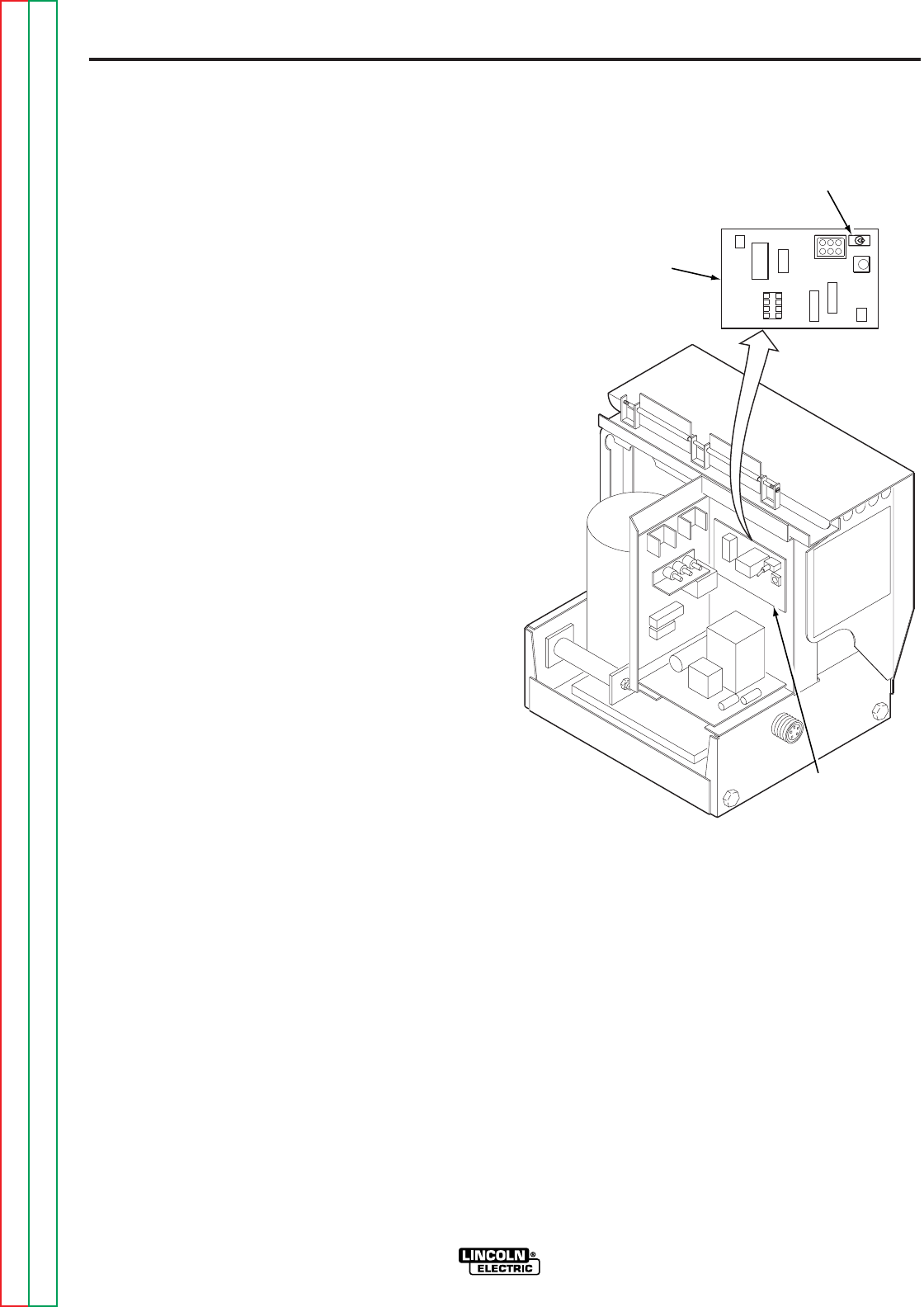
LN-8S AND LN-8SE (AND CONVERTED
LN-8N AND LN-8NE)
1. Use either a constant voltage or constant current
type power source as required for the application.
Ensure the power source is properly set for
constant voltage or constant current welding, as
appropriate, per the instructions in the power
source operating manual.
2. Set the LN-8 wire feeder for a constant voltage or
constant current power source as appropriate per
the following:
a. There are two nameplates on the front of the
wire feeder, one mounted on top of the other.
Be sure the ‘Constant Current Power Source’
nameplate is on top when using a constant
current power source. When connected to a
constant voltage power source, be sure the
‘Constant Voltage Power Source’ nameplate is
on top.
b. Turn the power to the wire feeder off. Open the
door to the control section and switch the
power source selection switch to constant
current ‘CC’ or constant voltage ‘CV’ as
appropriate. See Figure A.1.
3. Connect the LN-8 input cable to the power source
exactly as specified in the wire connection
diagrams in Table A.2. Include any jumpers on
the terminal strips as shown in the connection
diagrams.
4. Connect a work lead of sufficient size and length,
per Table A.1, between the appropriate output
terminal on the power source and the work.
Ensure the connection to the work makes tight
metal-to-metal contact.
FIGURE A.1 – POWER SOURCE SELECTION
SWITCH
POWER SOURCE
SELECTION SWITCH
VARIABLE
VOLTAGE
PC BOARD
VARIABLE
VOLTAGE
PC BOARD

Return to Section TOC Return to Section TOC Return to Section TOC Return to Section TOC
Return to Master TOC Return to Master TOC Return to Master TOC Return to Master TOC
A-5
INSTALLATION
LN-8
A-5
Figure No. Power Source
A.2 Connection of LN-8 to an Idealarc® R3S-400, 600 or 800 (with LVC) (Discontinued)
A.3 Connection of LN-8 to an Idealarc R3S-400, 600 or 800 (without LVC) (Discontinued)
A.4 Connection of LN-8 to a SAM Motor-Generator or Engine Driven Welder
A.5 Connection of LN-8 to R3S-250 and R3S-325
A.6 Connection of LN-8 to DC-600
A.7 Connection of LN-8 to DC-250, 400 and CV/CVI Power Sources
A.8 K318 Duel Process Contactor Kit
DC-400, CV-400, and CVI-500 Connection to LN-8 for Same Polarity Operation
A.9 K318 Duel Process Contactor Kit
DC-400, CV-400, and CVI-500 Connection to LN-8 for Opposite Polarity Operation
A.10 Power Sources other than Lincoln Electric
POWER SOURCE CONNECTION DIAGRAMS
Table A.2 – LN-8 Power Source Connection Diagrams
Return to Section TOC Return to Section TOC Return to Section TOC Return to Section TOC
Return to Master TOC Return to Master TOC Return to Master TOC Return to Master TOC
A-6
INSTALLATION
A-6
LN-8
ELECTRIC
SHOCK
CAN KILL
TURN OFF INPUT POWER
TO THE WELDING POWER
SOURCE USING THE
DISCONNECT SWITCH
BEFORE WORKING
ON THIS EQUIPMENT.
WARNING
24 21
POWER SOURCE
TO WORK
ELECTRODE CABLE TO
WIRE FEED UNIT
NEGATIVE
31 32
21
2
31
32
GND
A
B
C
4
75 76 77
TO OPTIONAL R3S
LINE VOLTAGE
COMPENSATOR
TO LN-8
INPUT CABLE PLUG
LN-8 CONTROL
CABLE
N.D.
N.B.
N.C.
N.B.
N.A.
THE ABOVE DIAGRAM SHOWS THE ELECTRODE CONNECTED FOR POSITIVE POLARITY. TO CHANGE POLARITY, TURN OFF THE POWER,
REVERSE THE ELECTRODE AND "TO WORK" LEADS AT THE POWER SOURCE, AND REVERSE THE "CONTROL SWITCH" AT THE POWER
SOURCE.
CONNECT THE LN-8 CONTROL CABLE GROUND LEAD TO THE FRAME TERMINAL MARKED NEAR THE POWER SOURCE TERMINAL STRIP
OR TO AN UNPAINTED FRAME SCREW. THE POWER SOURCE MUST BE PROPERLY GROUNDED.
N.A. ON EARLIER R3S-400, -600, AND -800 MACHINES, TERMINALS #67 AND #1 WERE ALSO ON THE TERMINAL STRIP.
N.B. WELDING CABLES MUST BE OF PROPER CAPACITY FOR THE CURRENT AND DUTY CYCLE OF IMMEDIATE AND FUTURE APPLICATIONS.
N.C. EXTEND LEAD #21 USING #14 OR LARGER INSULATED WIRE PHYSICALLY SUITABLE FOR THE INSTALLATION. AN S16586-[ ]
REMOTE VOLTAGE SENSING WORK LEAD IS AVAILABLE FOR THIS PURPOSE. CONNECT IT DIRECTLY TO THE WORK PIECE, KEEPING IT
ELECTRICALLY SEPARATE FROM THE WELDING WORK LEAD CIRCUIT AND CONNECTION. FOR CONVENIENCE, THIS EXTENDED LEAD
#21 SHOULD BE TAPED TO THE WELDING WORK LEAD. (THIS EXTENDED #21 LEAD CONNECTION REPLACES THE NEED TO EMPLOY THE
REMOTE WORK LEAD ACCESSORY ON LN-8 METER KITS WHICH HAVE A DIRECT WORK LEAD JACK).
N.D. LN-8 LEADS A, B, AND C (#75, #76, AND #77 ON OLDER LN-8 CONTROL CABLES) ARE TAPED UP WHEN THE R3S LINE VOLTAGE
COMPENSATOR IS CONNECTED. ARC VOLTAGE IS CONTROLLED BY THE LINE VOLTAGE COMPENSATOR RHEOSTAT. THERE WILL BE NO
ADJUSTMENTS OF VOLTAGE BY THE LN-8 VOLTAGE CONTROL.
TAPE UP BOLTED CONNECTION
POSITIVE
FIGURE A.2 – CONNECTION OF LN-8 TO AN IDEALARC R3S-400, 600 OR 800
(WITH LVC) (DISCONTINUED)
CLEVELAND, OHIO U.S.A.
Return to Section TOC Return to Section TOC Return to Section TOC Return to Section TOC
Return to Master TOC Return to Master TOC Return to Master TOC Return to Master TOC
A-7
INSTALLATION
A-7
LN-8
ELECTRIC
SHOCK
CAN KILL
TURN OFF INPUT POWER
TO THE WELDING POWER
SOURCE USING THE
DISCONNECT SWITCH
BEFORE WORKING
ON THIS EQUIPMENT.
WARNING
24 21
POWER SOURCE
TO WORK
ELECTRODE CABLE TO
WIRE FEED UNIT
NEGATIVE
31 32
21
2
31
32
GND
C
B
A
4
75 76 77
TO LN-8
INPUT CABLE PLUG
LN-8 CONTROL
CABLE
N.D.
N.B.
N.C.
N.B.
N.A.
THE ABOVE DIAGRAM SHOWS THE ELECTRODE CONNECTED FOR POSITIVE POLARITY. TO CHANGE POLARITY, TURN OFF THE POWER,
REVERSE THE ELECTRODE AND "TO WORK" LEADS AT THE POWER SOURCE, AND REVERSE THE "CONTROL SWITCH" AT THE POWER
SOURCE.
CONNECT THE LN-8 CONTROL CABLE GROUND LEAD TO THE FRAME TERMINAL MARKED NEAR THE POWER SOURCE TERMINAL STRIP
OR TO AN UNPAINTED FRAME SCREW. THE POWER SOURCE MUST BE PROPERLY GROUNDED.
N.A. ON EARLIER R3S-400, -600, AND -800 MACHINES, TERMINALS #67 AND #1 WERE ALSO ON THE TERMINAL STRIP.
N.B. WELDING CABLES MUST BE OF PROPER CAPACITY FOR THE CURRENT AND DUTY CYCLE OF IMMEDIATE AND FUTURE APPLICATIONS.
N.C. EXTEND LEAD #21 USING #14 OR LARGER INSULATED WIRE PHYSICALLY SUITABLE FOR THE INSTALLATION. AN S16586-[ ]
REMOTE VOLTAGE SENSING WORK LEAD IS AVAILABLE FOR THIS PURPOSE. CONNECT IT DIRECTLY TO THE WORK PIECE, KEEPING IT
ELECTRICALLY SEPARATE FROM THE WELDING WORK LEAD CIRCUIT AND CONNECTION. FOR CONVENIENCE, THIS EXTENDED LEAD
#21 SHOULD BE TAPED TO THE WELDING WORK LEAD. (THIS EXTENDED #21 LEAD CONNECTION REPLACES THE NEED TO EMPLOY THE
REMOTE WORK LEAD ACCESSORY ON LN-8 METER KITS WHICH HAVE A DIRECT WORK LEAD JACK).
N.D. IF USING AN OLDER LN-8 CONTROL CABLE (PRIOR TO USE OF A, B, AND C MARKING): CONNECT LEAD #75 TO #75 ON THE TERMINAL
STRIP, CONNECT LEAD #76 TO #76 ON THE TERMINAL STRIP, AND CONNECT LEAD #77 TO #77 ON THE TERMINAL STRIP.
N.E. UPPER TERMINAL STRIP (#75, #76 AND #77) MAY NOT APPEAR ON OLDER R3S MACHINES. LEADS A, B, AND C SHOULD BE TAPED UP.
THERE WILL BE NO ADJUSTMENT OF VOLTAGE BY THE LN-8 VOLTAGE CONTROL.
TAPE UP BOLTED CONNECTION
POSITIVE
N.E.
FIGURE A.3 – CONNECTION OF LN-8 TO AN IDEALARC R3S-400, 600 OR 800
(WITHOUT LVC) (DISCONTINUED)
CLEVELAND, OHIO U.S.A.
Return to Section TOC Return to Section TOC Return to Section TOC Return to Section TOC
Return to Master TOC Return to Master TOC Return to Master TOC Return to Master TOC
A-8
INSTALLATION
A-8
LN-8
ELECTRIC
SHOCK
CAN KILL
TURN OFF INPUT POWER
TO THE WELDING POWER
SOURCE USING THE
DISCONNECT SWITCH
BEFORE WORKING
ON THIS EQUIPMENT.
WARNING
TO WORK
TO LN-8 INPUT
CABLE PLUG
ELECTRODE CABLE TO
WIRE FEED UNIT
21
2
31
32
GND
A
B
C
4
AUTO
EQUIP. STICK WORK
TAPE
UP
67
21
2
31
32
C4
76
77
75
N.A.
CONTROL CABLE
N.B.
CONNECT THE LN-8 CONTROL CABLE GROUND LEAD TO THE FRAME TERMINAL MARKED NEAR THE POWER SOURCE TERMINAL STRIP
OR TO AN UNPAINTED FRAME SCREW. THE POWER SOURCE MUST BE PROPERLY GROUNDED.
N.A. EXTEND LEAD #21 USING #14 OR LARGER INSULATED WIRE PHYSICALLY SUITABLE FOR THE INSTALLATION. AN S16586-[ ]
REMOTE VOLTAGE SENSING WORK LEAD IS AVAILABLE FOR THIS PURPOSE. CONNECT IT DIRECTLY TO THE WORK PIECE, KEEPING IT
ELECTRICALLY SEPARATE FROM THE WELDING WORK LEAD CIRCUIT AND CONNECTION. FOR CONVENIENCE, THIS EXTENDED LEAD #21
SHOULD BE TAPED TO THE WELDING WORK LEAD. (THIS EXTENDED #21 LEAD CONNECTION REPLACES THE NEED TO EMPLOY THE
REMOTE WORK LEAD ACCESSORY ON LN-8 METER KITS WHICH HAVE A DIRECT WORK LEAD JACK).
N.B. IF USING AN OLDER LN-8 CONTROL CABLE (PRIOR TO USE OF A, B, AND C MARKING): CONNECT LEAD #76 TO #76 ON TERMINAL
STRIP, CONNECT LEAD #77 TO #75 ON THE TERMINAL STRIP, AND TAPE UP LEAD #75.
1
REMOVE SAM PORTABLE FIELD CONTROL AND
CONNECT LEADS B AND C FROM LN-8 CONTROL CABLE.
DO NOT CONNECT LEAD A. LEAD MUST BE TAPED UP.
POWER
SOURCE
TAPE UP
BOLTED
CONNECTION
FIGURE A.4 – CONNECTION OF LN-8 TO A SAM MOTOR-GENERATOR OR ENGINE DRIVEN WELDER
CLEVELAND, OHIO U.S.A.
Return to Section TOC Return to Section TOC Return to Section TOC Return to Section TOC
Return to Master TOC Return to Master TOC Return to Master TOC Return to Master TOC
A-9
INSTALLATION
A-9
LN-8
ELECTRIC
SHOCK
CAN KILL
TURN OFF INPUT POWER
TO THE WELDING POWER
SOURCE USING THE
DISCONNECT SWITCH
BEFORE WORKING
ON THIS EQUIPMENT.
WARNING
TO WORK
TO LN-8 INPUT
CABLE PLUG
ELECTRODE CABLE TO LN-8 OR
NA-3 AUTOMATIC SHUNT
21
4
31
32
GND
A
B
C
2
4
21
32
76
77
75
N.B.
CONTROL CABLE
N.C.
THE ABOVE DIAGRAM SHOWS THE ELECTRODE CONNECTED FOR POSITIVE POLARITY. TO CHANGE POLARITY, TURN OFF THE POWER,
REVERSE THE ELECTRODE AND "TO WORK" LEADS AT THE POWER SOURCE, AND REVERSE THE 'CONTROL SWITCH' AT THE POWER
SOURCE.
CONNECT THE LN-8 CONTROL CABLE GROUND LEAD TO THE FRAME TERMINAL MARKED NEAR THE POWER SOURCE TERMINAL STRIP
OR TO AN UNPAINTED FRAME SCREW. THE POWER SOURCE MUST BE PROPERLY GROUNDED.
N.A. WELDING CABLES MUST BE OF PROPER CAPACITY FOR THE CURRENT AND DUTY CYCLE OF IMMEDIATE AND FUTURE APPLICATIONS.
N.B. EXTEND LEAD #21 USING #14 OR LARGER INSULATED WIRE PHYSICALLY SUITABLE FOR THE INSTALLATION. AN S16586-[ ]
REMOTE VOLTAGE SENSING WORK LEAD IS AVAILABLE FOR THIS PURPOSE. CONNECT IT DIRECTLY TO THE WORK PIECE, KEEPING IT
ELECTRICALLY SEPARATE FROM THE WELDING WORK LEAD CIRCUIT AND CONNECTION. FOR CONVENIENCE, THIS EXTENDED LEAD #21
SHOULD BE TAPED TO THE WELDING WORK LEAD. (THIS EXTENDED #21 LEAD CONNECTION REPLACES THE NEED TO EMPLOY THE
REMOTE WORK LEAD ACCESSORY ON LN-8 METER KITS WHICH HAVE A DIRECT WORK LEAD JACKET.)
N.C. IF USING AN OLDER LN-8 CONTROL CABLE (PRIOR TO USE OF A, B, AND C MARKING), CONNECT LEAD #75 TO #75 ON THE TERMINAL
STRIP, LEAD #76 TO #76 ON THE TERMINAL STRIP, AND CONNECT LEAD #77 TO #77 ON THE TERMINAL STRIP.
31
NEGATIVE POSITIVE
N.A.
POWER SOURCE
TAPE UP
BOLTED
CONNECTION
FIGURE A.5 – CONNECTION OF LN-8 TO R3S-250 AND R3S-325
CLEVELAND, OHIO U.S.A.
Return to Section TOC Return to Section TOC Return to Section TOC Return to Section TOC
Return to Master TOC Return to Master TOC Return to Master TOC Return to Master TOC
A-10
INSTALLATION
A-10
LN-8
ELECTRIC
SHOCK
CAN KILL
TURN OFF INPUT POWER
TO THE WELDING POWER
SOURCE USING THE
DISCONNECT SWITCH
BEFORE WORKING
ON THIS EQUIPMENT.
WARNING
THE ABOVE DIAGRAM SHOWS THE ELECTRODE CONNECTED POSITIVE. TO CHANGE POLARITY, TURN OFF THE POWER, REVERSE THE
ELECTRODE AND "TO WORK" LEADS AT THE POWER SOURCE, AND POSITION THE SWITCH ON THE POWER SOURCE TO PROPER
POLARITY.
N.A. WELDING CABLES MUST BE OF PROPER CAPACITY FOR THE CURRENT AND DUTY CYCLE OF IMMEDIATE AND FUTURE APPLICATIONS.
N.B. EXTEND LEAD #21 USING #14 OR LARGER INSULATED WIRE PHYSICALLY SUITABLE FOR THE INSTALLATION. AN S16586-[ ] REMOTE
VOLTAGE SENSING WORK LEAD IS AVAILABLE FOR THIS PURPOSE. CONNECT IT DIRECTLY TO THE WORK PIECE, KEEPING IT
ELECTRICALLY SEPARATE FROM THE WELDING WORK LEAD CIRCUIT AND CONNECTION. FOR CONVENIENCE, THIS EXTENDED LEAD #21
SHOULD BE TAPED TO THE WELDING WORK LEAD. (THIS EXTENDED #21 LEAD CONNECTION REPLACES THE NEED TO EMPLOY THE
REMOTE WORK LEAD ACCESSORY ON LN-8 METER KITS WHICH HAVE A DIRECT WORK LEAD JACK.)
N.C. TAPE UP BOLTED CONNECTION.
N.D. CONNECT THE LN-8 CONTROL CABLE GROUND LEAD TO THE FRAME TERMINAL MARKED NEAR THE POWER SOURCE TERMINAL
STRIP OR TO AN UNPAINTED FRAME SCREW. THE POWER SOURCE MUST BE PROPERLY GROUNDED.
N.E. IF USING AN OLDER LN-8 CONTROL CABLE (PRIOR TO USE OF A, B, AND C MARKING): CONNECT LEAD #75 TO #75 ON TERMINAL
STRIP, CONNECT LEAD #76 TO #76 ON TERMINAL STRIP, AND CONNECT LEAD #77 TO #77 ON TERMINAL STRIP.
N.F. FOR DC-600 CODES BELOW 8200, CONNECT A JUMPER FROM 'N' TO 'S' ON LN-8 ONLY. THERE IS NO NPS TERMINAL STRIP ON CODES
ABOVE 8200.
POWER SOURCE
C
B
A
32
31
21
2
4
GND
476
21 75
32 8127731 80
P
NS
TO WORK
ELECTRODE CABLE TO
WIRE FEED UNIT
POSITIVE
NEGATIVE
N.A.
N.E.
N.B. AND N.C.
TO LN-8 INPUT
CABLE PLUG
CONTROL
CABLE
N.F. N.D.
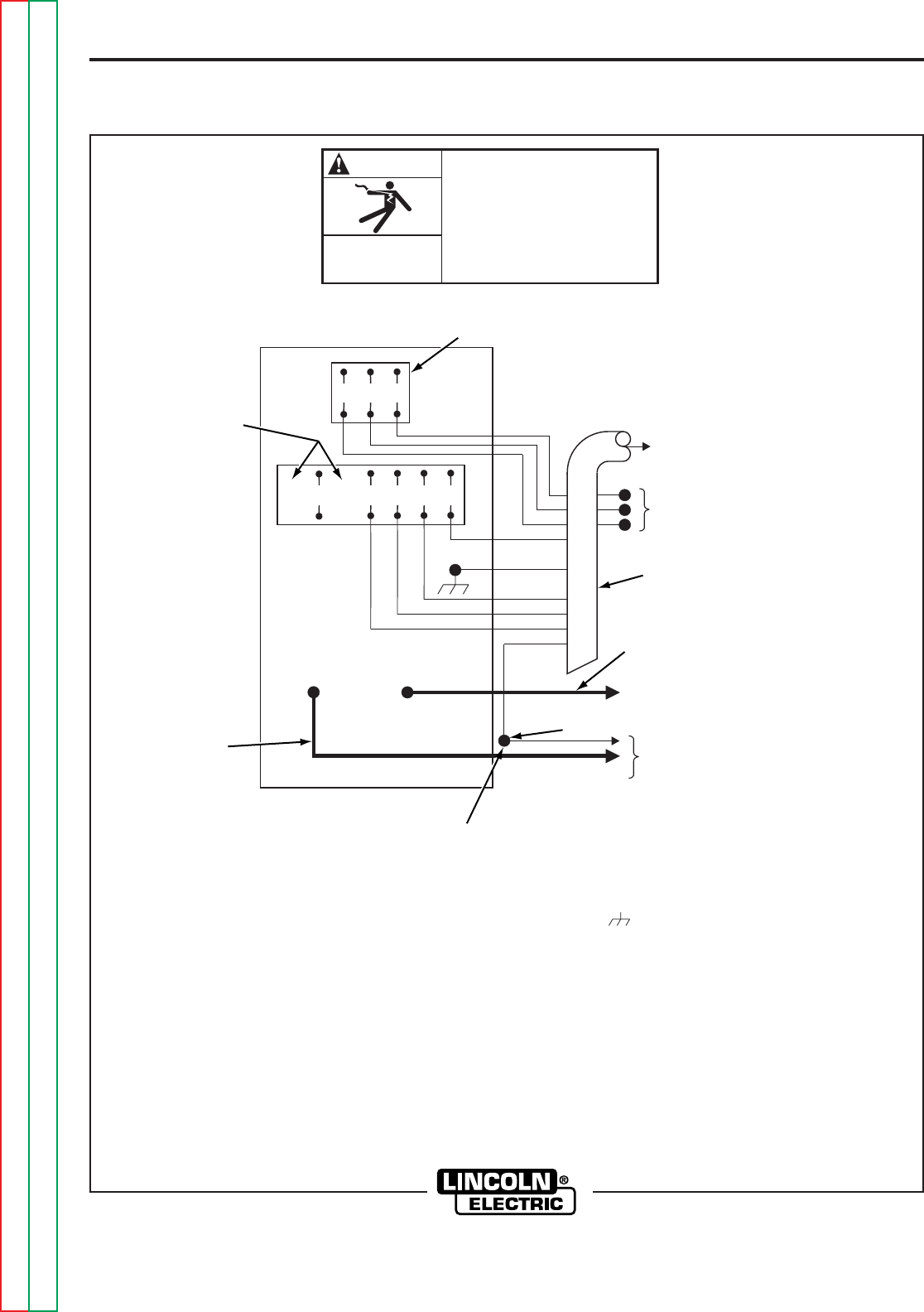
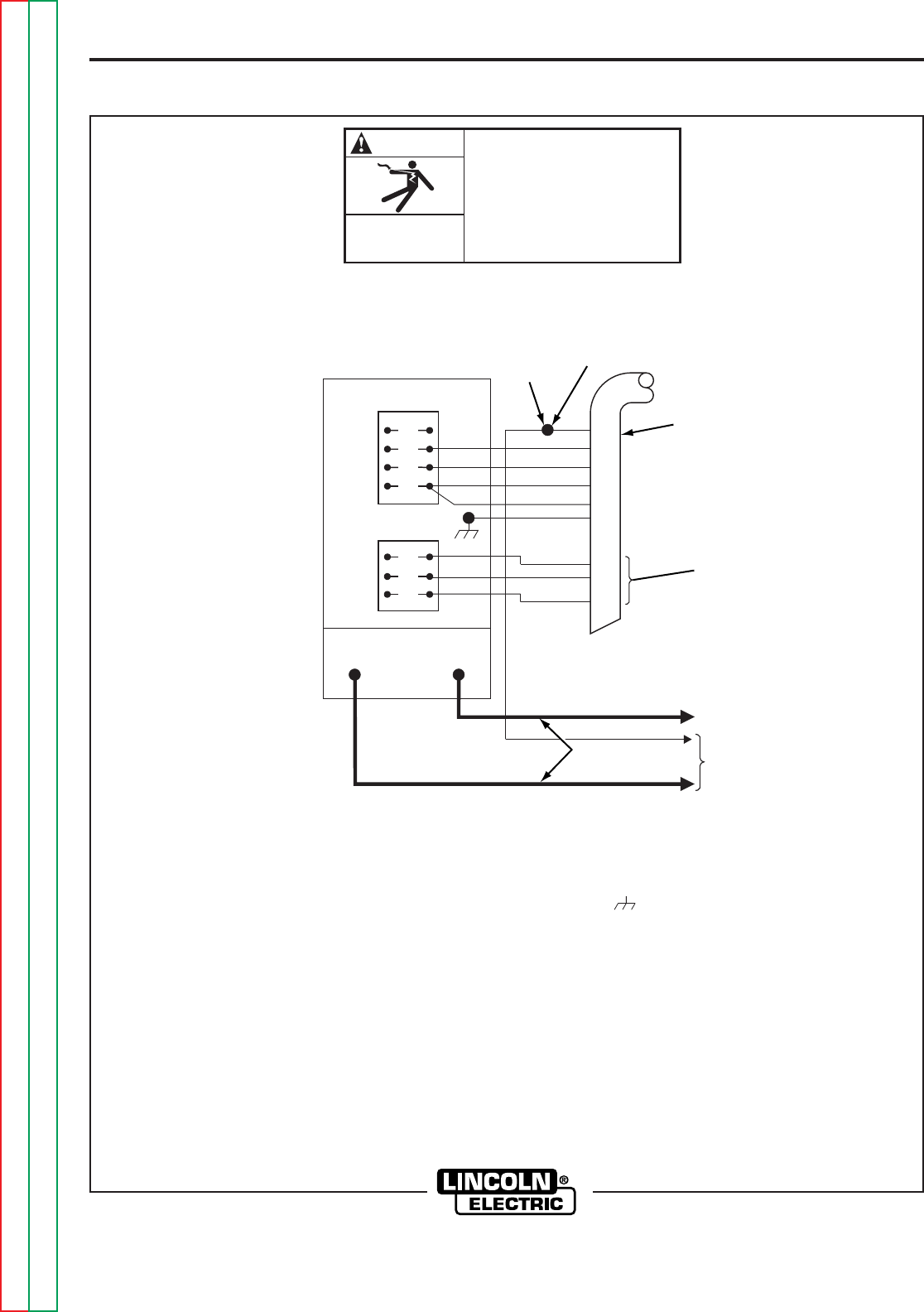
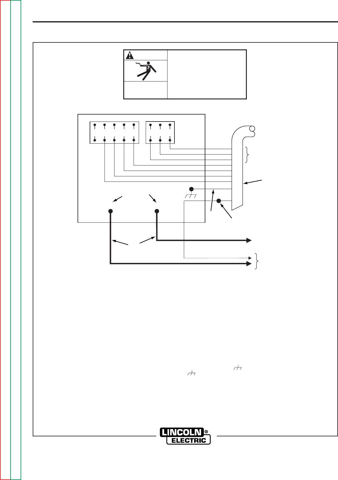
FIGURE A.6 – CONNECTION OF LN-8 TO DC-600
CLEVELAND, OHIO U.S.A.
Return to Section TOC Return to Section TOC Return to Section TOC Return to Section TOC
Return to Master TOC Return to Master TOC Return to Master TOC Return to Master TOC
A-11
INSTALLATION
A-11
LN-8
ELECTRIC
SHOCK
CAN KILL
TURN OFF INPUT POWER
TO THE WELDING POWER
SOURCE USING THE
DISCONNECT SWITCH
BEFORE WORKING
ON THIS EQUIPMENT.
WARNING
4
21 32
POWER SOURCE
TO WORK
ELECTRODE CABLE TO
WIRE FEED UNIT
NEGATIVE POSITIVE
231
GND
C
B
A
32
31
21
2
4
75 76 77 TO LN-8 INPUT
CABLE PLUG
CONTROL CABLE
N.B. AND N.C.
N.D.
N.E.
N.A.
THE ABOVE DIAGRAM SHOWS THE ELECTRODE CONNECTED POSITIVE. TO CHANGE POLARITY, TURN OFF THE POWER, REVERSE THE
ELECTRODE AND "TO WORK" LEADS AT THE POWER SOURCE, AND POSITION THE SWITCH ON THE POWER SOURCE AND WIRE FEEDER
(IF EQUIPPED) TO PROPER POLARITY. ALSO REFER TO THE FOLLOWING NOTE:
NOTE: IF LEAD #21 IS TO BE CONNECTED TO THE TERMINAL STRIP, CONNECT TO TERMINAL #21 THAT MATCHES WORK POLARITY. THIS
CONNECTION MUST BE CHANGED WHENEVER THE ELECTRODE POLARITY IS CHANGED. THIS DOES NOT APPLY TO DC-400 BELOW
CODE 9200 WITH POLARITY SWITCH.
N.A. WELDING CABLES MUST BE OF PROPER CAPACITY FOR THE CURRENT AND DUTY CYCLE OF IMMEDIATE AND FUTURE APPLICATIONS.
N.B. EXTEND LEAD #21 USING #14 OR LARGER INSULATED WIRE PHYSICALLY SUITABLE FOR THE INSTALLATION. AN S16586-[ ]
REMOTE VOLTAGE SENSING WORK LEAD IS AVAILABLE FOR THIS PURPOSE. CONNECT IT DIRECTLY TO THE WORK PIECE, KEEPING IT
ELECTRICALLY SEPARATE FROM THE WELDING WORK LEAD CIRCUIT AND CONNECTION. FOR CONVENIENCE, THIS EXTENDED LEAD #21
SHOULD BE TAPED TO THE WELDING WORK LEAD. (IF THE LENGTH OF THE WORK LEAD CIRCUIT IS SHORT, AND CONNECTIONS CAN BE
EXPECTED TO BE RELIABLE, THEN CONTROL CABLE LEAD #21 DOES NOT NEED TO BE EXTENDED AND CAN BE DIRECTLY CONNECTED
TO TERMINAL #21 ON THE TERMINAL STRIP. NOTE THAT THIS IS NOT THE PREFERRED CONNECTION BECAUSE IT ADDS ERROR TO THE
WIRE FEEDER VOLTMETER READING.)
N.C. TAPE UP BOLTED CONNECTION.
N.D. CONNECT THE LN-8 CONTROL CABLE GROUND LEAD TO THE FRAME TERMINAL MARKED NEAR THE POWER SOURCE TERMINAL
STRIP. THE POWER SOURCE GROUNDING TERMINAL STRIP (MARKED AND LOCATED NEAR THE POWER SOURCE INPUT POWER
CONNECTIONS) MUST BE PROPERLY CONNECTED TO ELECTRICAL GROUND PER THE POWER SOURCE OPERATING MANUAL.
N.E. IF USING AN OLDER LN-8 CONTROL CABLE (PRIOR TO USE OF A, B, AND C MARKING): CONNECT LEAD #75 TO #75 ON TERMINAL
STRIP, CONNECT LEAD #76 TO #76 ON TERMINAL STRIP, AND CONNECT LEAD #77 TO #77 ON THE TERMINAL STRIP.
CV OUTPUT
TERMINALS ON
DC-250
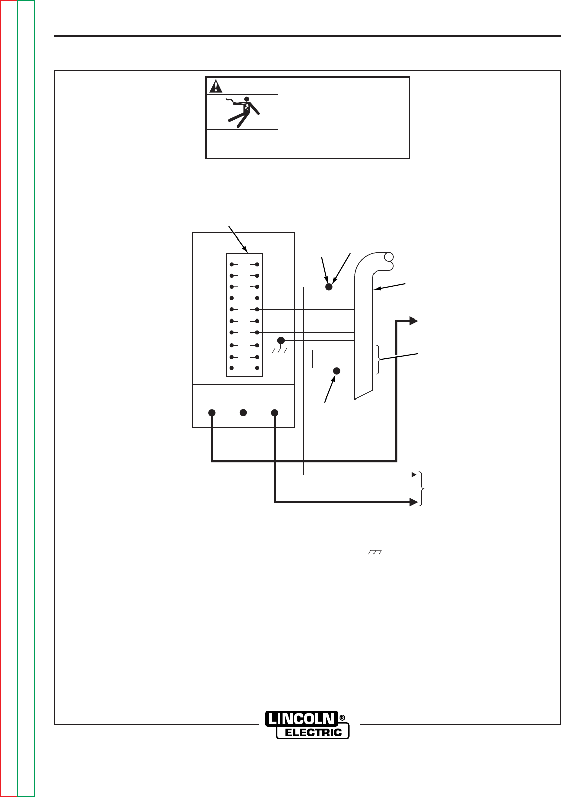
FIGURE A.7 – CONNECTION OF LN-8 TO DC-250, 400 AND CV/CVI POWER SOURCES
CLEVELAND, OHIO U.S.A.
Return to Section TOC Return to Section TOC Return to Section TOC Return to Section TOC
Return to Master TOC Return to Master TOC Return to Master TOC Return to Master TOC
A-12
INSTALLATION
A-12
LN-8
GND
77
76
75
32
31
2
4
A
B
C
4
2
GND
32
31
21
DUAL PROCESS
CONTACTOR
4
2
32
31
75
76
77
A
A
4
2
32
31
75
76
77
B
B
A
B
C
4
2
GND
32
31
21
81
80
ELECTRIC
SHOCK
CAN KILL
TURN OFF INPUT POWER
TO THE WELDING POWER
SOURCE USING THE
DISCONNECT SWITCH
BEFORE WORKING
ON THIS EQUIPMENT.
WARNING
4
21 32
DC-400
TO WORK
TO NEGATIVE OUTPUT
STUD ON POWER
SOURCE
TO POSITIVE OUTPUT
STUD ON POWER
SOURCE
231 75 76 77
WELDER
CONTROL
CABLE
N.A.
N.C.
N.F.
21A 21B
N.B.B.
WELDING LEAD STUD ON
BACK OF CONTACTOR KIT
N.E.
N.A.
N.D.
ELECTRODE
CABLES
WIRE FEEDER
CONTROL
CABLE
WIRE FEEDER
CONTROL
CABLE
TO "A" WIRE FEEDER TO "B" WIRE FEEDER
N.B. N.B.
N.A.A.
FOR 50 HZ OPERATION, DISCONNECT BOTH BROWN LEADS FROM TERMINAL 31B AND TAPE UP EACH LEAD. UNTAPE BOTH RED LEADS AND
CONNECT TO 31B.
N.A.A. CONNECT THE LN-8 CONTROL CABLE GROUND LEAD TO THE FRAME TERMINAL MARKED NEAR THE POWER SOURCE TERMINAL
STRIP OR TO AN UNPAINTED FRAME SCREW. THE POWER SOURCE MUST BE PROPERLY GROUNDED.
N.B.B. EXTEND LEAD #21A & #21B USING #14 OR LARGER INSULATED WIRE PHYSICALLY SUITABLE FOR THE INSTALLATION. AN S16586-[]
REMOTE VOLTAGE SENSING WORK LEAD IS AVAILABLE FOR THIS PURPOSE. CONNECT IT DIRECTLY TO THE WORK PIECE KEEPING IT
ELECTRICALLY SEPARATE FROM THE WELDING LEAD CIRCUIT AND CONNECTION. FOR CONVENIENCE, THESE EXTENDED #21A AND #21B
LEADS SHOULD BE TAPED TO THE WELDING WORK LEAD. EACH LEAD MUST BE CONNECTED DIRECTLY TO THE WORK AND LEADS MUST
NOT BE CONNECTED TOGETHER.
N.A. WELDING CABLES MUST BE OF PROPER CAPACITY FOR THE CURRENT AND DUTY CYCLE OF IMMEDIATE AND FUTURE APPLICATIONS.
N.B. BOLT AND TAPE CONNECTIONS.
N.C. TAPE UP SEPARATELY.
N.D. PUT TRANSFER SWITCH IN "SAME POLARITY ON FEEDERS" POSITION.
N.E. MODE SWITCHES ON CONTACTOR KIT ARE NOT FUNCTIONAL WHEN USED WITH THE POWER SOURCE.
N.F. CONNECTION SHOWN FOR NEGATIVE POLARITY. FOR POSITIVE POLARITY REVERSE ELECTRODE AND WORK CABLES CONNECTED TO
POWER SOURCE OUTPUT STUDS.
N.B.B.
N.A.
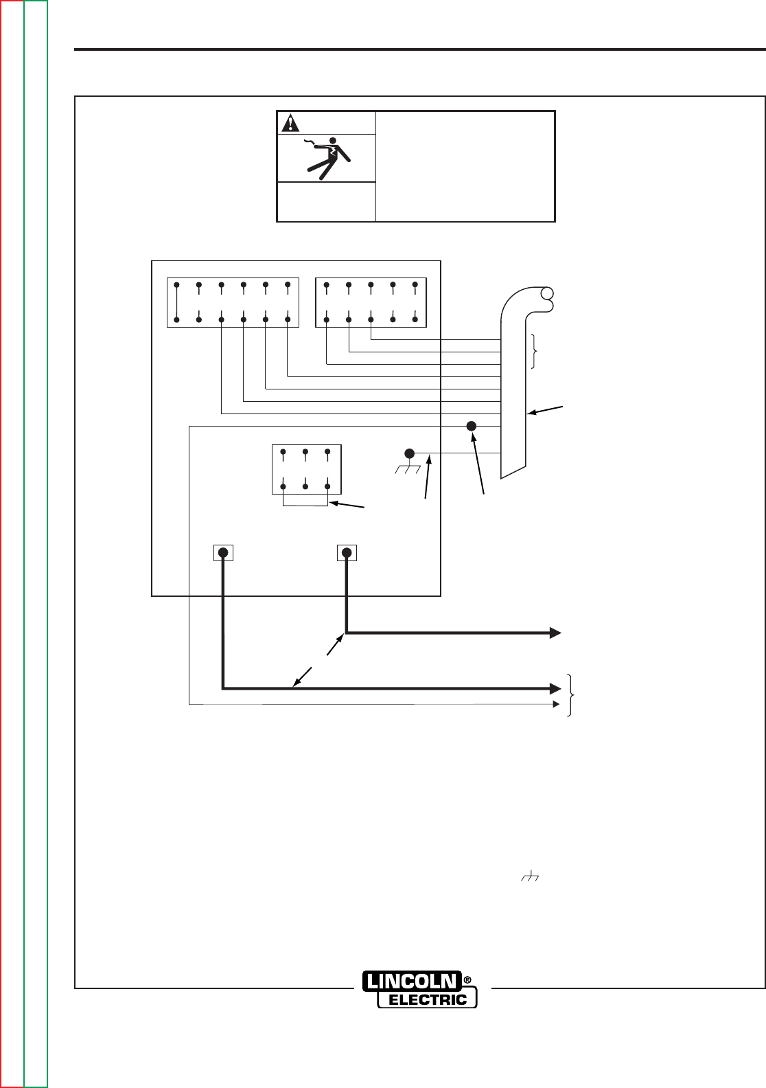
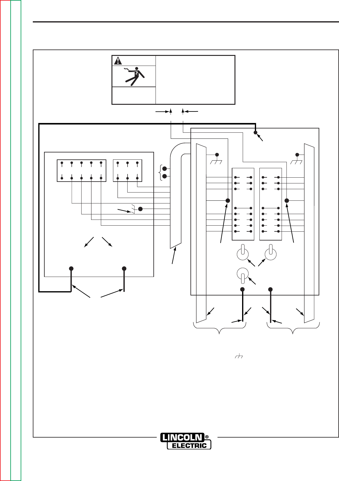
FIGURE A.8 – K318 DUAL PROCESS CONTACTOR KIT DC-400, CV-400 AND CVI-500 CONNECTION TO
LN-8 FOR SAME POLARITY OPERATION
CLEVELAND, OHIO U.S.A.
Return to Section TOC Return to Section TOC Return to Section TOC Return to Section TOC
Return to Master TOC Return to Master TOC Return to Master TOC Return to Master TOC
A-13
INSTALLATION
A-13
LN-8
GND
77
76
75
32
31
2
4
A
B
C
4
2
GND
32
31
21
DUAL PROCESS
CONTACTOR
4
2
32
31
75
76
77
A
A
4
2
32
31
75
76
77
B
B
A
B
C
4
2
GND
32
31
21
81
80
ELECTRIC
SHOCK
CAN KILL
TURN OFF INPUT POWER
TO THE WELDING POWER
SOURCE USING THE
DISCONNECT SWITCH
BEFORE WORKING
ON THIS EQUIPMENT.
WARNING
4
21 32
DC-400
TO WORK
TO NEGATIVE OUTPUT
STUD ON POWER
SOURCE
TO POSITIVE OUTPUT
STUD ON POWER
SOURCE
231 75 76 77
WELDER
CONTROL
CABLE
N.A.
N.C.
N.F.
21A 21B
N.B.B.
WELDING LEAD STUD ON
BACK OF CONTACTOR KIT
N.E.
N.A.
N.D.
ELECTRODE
CABLES
WIRE FEEDER
CONTROL
CABLE
WIRE FEEDER
CONTROL
CABLE
TO "A" WIRE FEEDER
ELECTRODE NEGATIVE
TO "B" WIRE FEEDER
ELECTRODE POSITIVE
N.B. N.B.
N.A.
FOR 50 HZ OPERATION, DISCONNECT BOTH BROWN LEADS FROM TERMINAL 31B AND TAPE UP EACH LEAD. UNTAPE BOTH RED LEADS
AND CONNECT TO 31B.
N.A.A. CONNECT THE LN-8 CONTROL CABLE GROUND LEAD TO THE FRAME MARKED NEAR THE POWER SOURCE TERMINAL STRIP OR
TO AN UNPAINTED FRAME SCREW. THE POWER SOURCE MUST BE PROPERLY GROUNDED.
N.B.B. EXTEND LEAD #21A AND #21B USING #14 OR LARGER INSULATED WIRE PHYSICALLY SUITABLE FOR THE INSTALLATION. AN S16586-[]
REMOTE VOLTAGE SENSING WORK LEAD IS AVAILABLE FOR THIS PURPOSE. CONNECT IT DIRECTLY TO THE WORK PIECE, KEEPING IT
ELECTRICALLY SEPARATE FROM THE WELDING WORK LEAD CIRCUIT AND CONNECTION. FOR CONVENIENCE, THESE EXTENDED #21A AND
#21B LEADS SHOULD BE TAPED TO THE WELDING WORK LEAD. EACH LEAD MUST BE CONNECTED DIRECTLY TO THE WORK AND LEADS
MUST NOT BE CONNECTED TOGETHER.
N.A. WELDING CABLES MUST BE OF PROPER CAPACITY FOR THE CURRENT AND DUTY CYCLE OF IMMEDIATE AND FUTURE APPLICATIONS.
N.B. BOLT AND TAPE CONNECTIONS.
N.C. TAPE UP SEPARATELY.
N.D. PUT TRANSFER SWITCH IN "OPPOSITE POLARITY ON FEEDERS" POSITION.
N.E. MODE SWITCHES ON CONTACTOR KIT ARE NOT FUNCTIONAL WHEN USED WITH THE POWER SOURCE.
N.F. TO MAKE "A" FEEDER POSITIVE POLARITY AND "B" FEEDER NEGATIVE POLARITY, REVERSE ELECTRODE CABLES CONNECTED TO
POWER SOURCE OUTPUT STUDS.
N.A.A.
N.B.B.
N.A.
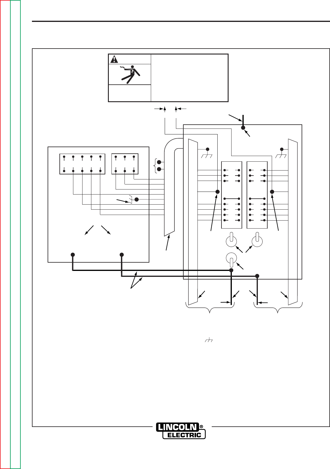
FIGURE A.9 – K318 DUAL PROCESS CONTACTOR KIT DC-400, CV-400 AND CVI-500 CONNECTION TO
LN-8 FOR OPPOSITE POLARITY OPERATION
CLEVELAND, OHIO U.S.A.
Return to Section TOC Return to Section TOC Return to Section TOC Return to Section TOC
Return to Master TOC Return to Master TOC Return to Master TOC Return to Master TOC
A-14
INSTALLATION
A-14
LN-8
ELECTRIC
SHOCK
CAN KILL
TURN OFF INPUT POWER
TO THE WELDING POWER
SOURCE USING THE
DISCONNECT SWITCH
BEFORE WORKING
ON THIS EQUIPMENT.
WARNING
REFER TO THE POWER SOURCE WIRING DIAGRAM TO FIND THE TYPE OF CONTACTOR CIRCUIT.
INTERNALLY POWERED CONTACTOR EXTERNALLY POWERED CONTACTOR
OUTPUT CONTACTOR COIL OUTPUT CONTACTOR COIL
(115 VAC)
WORK WORK
TO
WORK
TO
WORK
ELECTRODE ELECTRODE
FOR POWER TO
OPERATE CONTACTOR
MAX. RATING OR LN-8
#2 TO #4 CIRCUIT IS
5 AMP 115 VAC OR
5 AMP 28 VDC
1/2 AMP 115 VDC
MAX. RATING OF LN-8
#2 TO #4 CIRCUIT IS
5 AMP 115 VAC
5 AMP 28 VDC
1/2 AMP 115 VDC
TO 115 VAC 350
VOLT-AMP CAPACITY
TO 115 VAC 350 VOLT-AMP
FOR LN-8 PLUS
CONTACTOR
REQUIREMENTS
TAPE UP
EACH LEAD
TAPE UP
EACH LEAD
TO LN-8 CIRCUIT TO LN-8 CIRCUIT
LN-8 WIRE FEEDER LN-8 WIRE FEEDER
ELECTRODE CABLE ELECTRODE CABLE
POWER SOURCE POWER SOURCE
INPUT
CONTROL
CABLE
INPUT
CONTROL
CABLE
GND GND
21 21
31 31
32 32
75 75
76 76
77 77
31 3132 322244
44
22
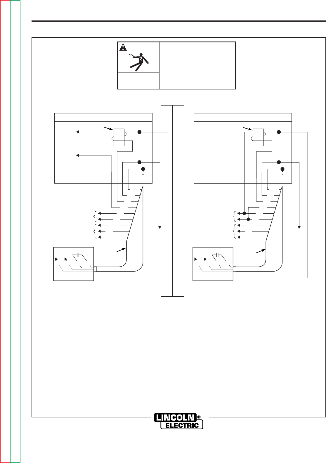
FIGURE A.10 – FOR POWER SOURCES OTHER THAN LINCOLN ELECTRIC
CLEVELAND, OHIO U.S.A.
Return to Section TOC Return to Section TOC Return to Section TOC Return to Section TOC
Return to Master TOC Return to Master TOC Return to Master TOC Return to Master TOC
A-15
INSTALLATION
LN-8
A-15
INPUT CABLE CONNECTIONS
For connecting an LN-8 to a specific Lincoln Electric
power source, use the appropriate steps in one of
these paragraphs and refer to the connection dia-
grams listed on Table A.2 for the applicable power
source. Table A.2 lists each figure number with its
corresponding power source.
LN-8N AND LN-8S
The input cable consists of an electrode cable and a
multi-conductor control cable. The control cable has a
polarized plug on the wire feeder end. To connect the
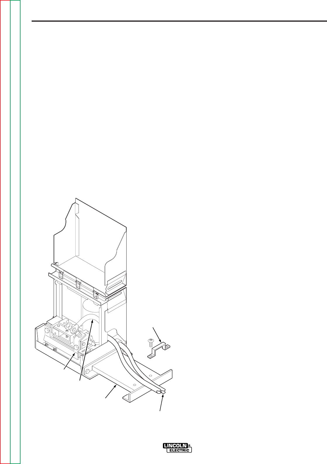
cables, refer to Figure A.11 and perform these steps:
1. Connect the polarized plug of the control cable to
the mating connector on the back of the wire
feeder.
FIGURE A.11 – INPUT CONTROL CABLE AND
ELECTRODE CABLE CONNECTIONS
2. Remove the screws holding the cable clamp
located near the rear of the wire reel base. Put
the control cable and electrode cable under the
clamp and install the screws. On cables with
more than one electrode cable, leave the junction
between the two or more cables and the single
4/0 stub behind the clamp so only the single
electrode lead is under the clamp.
3. Pass the single electrode cable through the holes
provided in the back corner of the control section
and fasten it to the tab on the conductor above
the rear brass block of the wire feeder.
LN-8NE AND LN-8SE
The extension unit consists of a wire reel mount with
a hand crank and either a 22-1/2 or 45 ft (6.9 or
13.7 m) extension cable assembly. The cable is rated
at 450 amps, 50% duty cycle. For higher currents
install a parallel length of 1/0 cable per step 10. The
extension cable can be used for 0.068 through
0.120 in. (1.7 through 3.0 mm) flux-cored electrode
and 5/64 through 3/32 in. (2.0 through 2.4 mm) solid
electrode. The 22-1/2 ft. (6.9 m) cables can also be
used for 1/16 in. (1.6 mm) solid electrodes. To con-
nect the cables, perform these steps:
1. When shipped, the hand crank on the wire reel
mount is equipped to feed 1/16 through 0.120 in.
(1.6 through 3.0 mm) electrode.
WIRE
REEL
BASE
CONTROL
CABLE
CABLE
CLAMP
ELECTRODE
CABLE
CONDUCTOR
Return to Section TOC Return to Section TOC Return to Section TOC Return to Section TOC
Return to Master TOC Return to Master TOC Return to Master TOC Return to Master TOC
A-16
INSTALLATION
LN-8
A-16
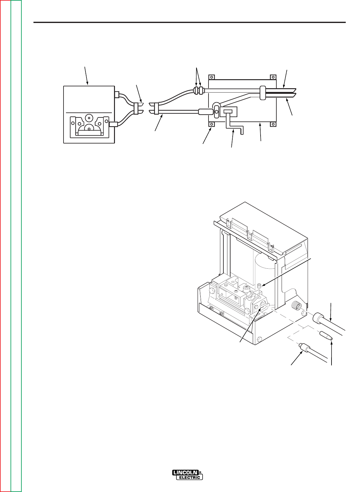
2. The standard cable setup consists of an electrode
cable and a control cable with a polarized plug on
the wire feeder end. Position the control cable
with the polarized plug at the wire reel base. Refer
to Figure A.12.
3. Connect the electrode cable to the brass block on
the hand crank assembly using the screw
provided.
4. Position the 22-1/2 or 45 ft (6.9 or 13.7 m) control
cable extension so the polarized connector with
the threads on its O.D. is at the wire reel base.
5. Connect the polarized connectors of the control
cable together.
6. Place both the control and electrode cables under
the clamp on the wire reel base and tighten the
screws.
7. Insert the connector on the electrode cable
extension into the brass block of the hand crank
assembly and tighten with a 3/16 in. Allen wrench.
8. At the wire feeder, connect the polarized plug of
the control cable extension into the mating
receptacle on the back of the wire feeder. Refer to
Figure A.13.
FIGURE A.13 – CABLE EXTENSION
CONNECTIONS TO WIRE FEEDER
WIRE
DRIVE
UNIT CONTROL
CABLE
EXTENSION
POLARIZED
PLUGS CONTROL
CABLE
ELECTRODE
CABLE
HAND
CRANK
BRASS
BLOCK
ELECTRODE
EXTENSION
CABLE WIRE
REEL
BASE
FIGURE A.12 – INPUT CONTROL CABLE AND ELECTRODE CABLE EXTENSIONS
LOCKING
SCREW
CONTROL
CABLE
EXTENSION
REAR
BRASS
BLOCK
ELECTRODE
CABLE
EXTENSION
CONNECTOR
INGOING
GUIDE
TUBE
Return to Section TOC Return to Section TOC Return to Section TOC Return to Section TOC
Return to Master TOC Return to Master TOC Return to Master TOC Return to Master TOC
A-17
INSTALLATION
LN-8
A-17
9. Remove the ingoing guide tube from the rear
brass block of the wire feeder and plug the
connector of the electrode cable extension into
the brass block. Tighten the locking screw with a
3/16 in. Allen wrench. The guide tube is not used
when the extension assembly is installed.
10. If using over 450 amperes, connect a length of
1/0 cable between the brass block on the wire reel
base and the tab on the rear brass block of the
wire feeder. Tape this cable to the extension
assembly. Proper cable lengths are:
•For a 22-1/2 ft (6.9 m) extension use 23-1/2 ft
(7.2 m) - order M5906-106
•For 45 ft (13.7 m) extension use 46 ft (14 m) -
order M5906-104
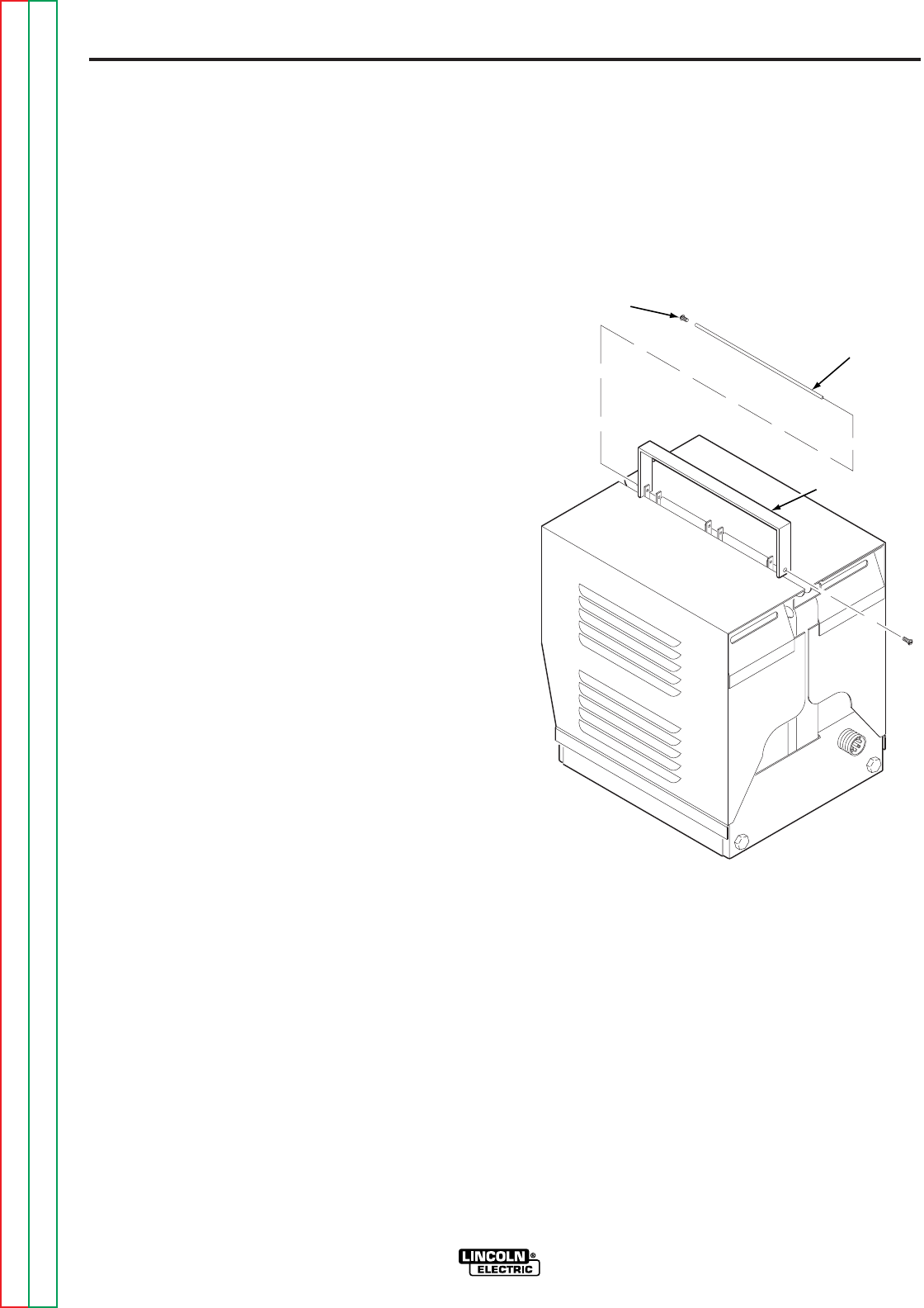
11. To mount the wire feeder handle provided with
the extension unit, remove the two self-tapping
screws that hold the hinge pin in the top of the
wire feeder. Push the hinge pin out, leaving the
covers intact. Place the handles into the slots
provided and push the hinge pin back into the
assembly making sure that the pin goes through
the holes in the handle. Put the two self-tapping
screws back into their respective positions. Refer
to Figure A.14.
12. If the extension is being used with a K306 Wire
Reel Flux Tank assembly, the hose attached to
the bottom of the flux tank may have to be
shortened. This hose is 64 ft (19.5 m) long, and is
the correct length for use with the 45 ft (13.7 m)
extension. If a 22-1/2 ft (6.9 m) extension is to be
used, cut 22-1/2 ft (6.9 m) off the flux hose to give
the correct length of 41-1/2 ft (12.6 m). (The
conductor cable is 22-1/2 ft (6.9 m) long, tip to tip,
and can be used to measure the length of hose
cut off.) If the flux hose is taped to the extension
cables or gun cable, it should be done in such a
manner as not to deform or collapse the hose.
FIGURE A.14 – WIRE FEEDER HANDLE
INSTALLATION
SELF-TAPPING
SCREW
HINGE
PIN
HANDLE

Return to Section TOC Return to Section TOC Return to Section TOC Return to Section TOC
Return to Master TOC Return to Master TOC Return to Master TOC Return to Master TOC
A-18
INSTALLATION
LN-8
A-18
GUN AND CABLE ASSEMBLIES
GENERAL
The LN-8 is used with various guns. In all cases, the
gun is shipped connected to the cable and is ready to
weld. Use the gun recommended for the wire type
(solid or cored) and size to be used. See the para-
graph on Welding Guns in the Accessories Section
for more information on the different types of guns.
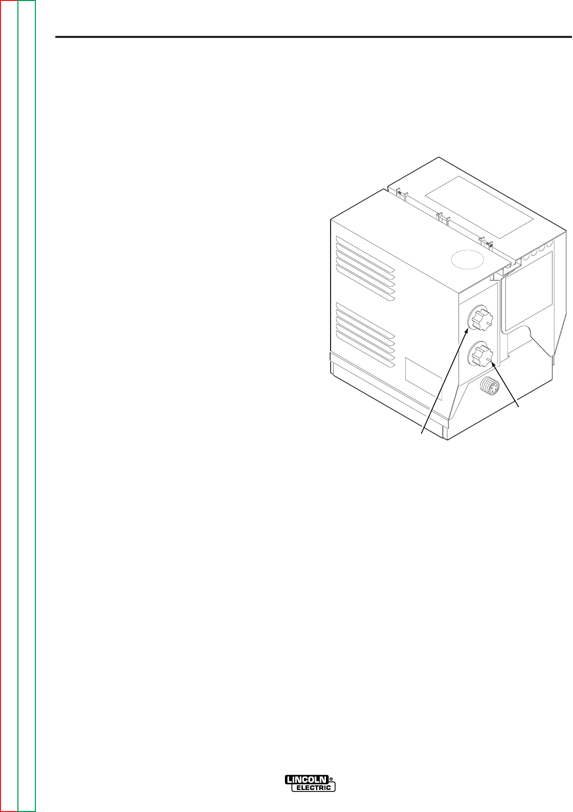
GUN CABLE CONNECTIONS
Lay the cable out straight. Insert the male end of the
welding conductor cable into the brass block on the
front of the LN-8. Make sure it is in all the way and
tighten the locking screw with a 3/16 in. Allen wrench.
Keep this connection clean and bright. Connect the
control cable polarized plug into the receptacle next to
the coupling.
HANDLING PROCEDURES
1. Do not kink or pull the cable around sharp
corners.
2. Keep the electrode cable as straight as practical
when welding or starting the electrode through
the cable.
3. Do not allow dolly wheels or trucks to run over the
cables.
4. Keep the cable clean by following the
maintenance instructions.
5. Use only clean, rust-free electrode wire.
6. Replace contact tip when the arc starts to become
unstable or the contact tip end is fused or
deformed.
LN-8S AND LN-8SE CONTINUOUS
FLUX FEED (SUBMERGED ARC)
Connect the loose end of the hose to the tube at the
back end of the welding gun. Tighten the hose clamp.
If the hose is taped to the gun cable, be sure it is not
collapsed or deformed as this could cause flux feed-
ing problems.
The air for the automatic flux feeding system is
obtained from the regular plant compressed air sys-
tem, providing the plant system pressure is between
60 and 120 psi (414 and 827 kPa). The tank is
equipped with a pressure regulator to reduce the input
pressure to the 30 psi (207 kPa) required for the flux
feeding system. This pressure is set at the factory
before the machine is shipped. When the LN-8SE
with the 22-1/2 or 45 ft. (6.9 or 13.7 m) extension is
used, and the flux hose is long, set the air pressure at
45 psi (310 kPa) for 1/2 in. (12 mm) I.D. hose, and 55
psi (379 kPa) for 3/8 in. (9.5 mm) I.D. hose. Exact
pressure is indicated on the pressure gage. Air con-
sumption is normally less than 1.5 cubic feet
(4.2 cubic meters) per minute of welding.
Connect the input air hose to the street elbow located
at the right side of the flux tank. A quick disconnect
should be installed between the elbow and the input
hose.
The air tank is equipped with a water and dirt separa-
tor. Water separated from the input air feeds down
through the long flux filled tube located at the input
connection. It is exhausted from the system through
the coiled tube below the flux tank. There is always a
small amount of air and possibly water coming out of
the end of this tube.

Return to Master TOC Return to Master TOC Return to Master TOC Return to Master TOC
OPERATION
LN-8
SECTION B-1SECTION B-1
TABLE OF CONTENTS
-OPERATION SECTION-
Operation . . . . . . . . . . . . . . . . . . . . . . . . . . . . . . . . . . . . . . . . . . . . . . . . . . . . . . . . . . . . . . . . Section B
Safety Instructions . . . . . . . . . . . . . . . . . . . . . . . . . . . . . . . . . . . . . . . . . . . . . . . . . . . . . . . B-2
Controls and Their Functions . . . . . . . . . . . . . . . . . . . . . . . . . . . . . . . . . . . . . . . . . . . . . . . B-2
Constant Current Controls . . . . . . . . . . . . . . . . . . . . . . . . . . . . . . . . . . . . . . . . . . . . . . B-2
Constant Voltage Controls . . . . . . . . . . . . . . . . . . . . . . . . . . . . . . . . . . . . . . . . . . . . . . B-3
Circuit Protection . . . . . . . . . . . . . . . . . . . . . . . . . . . . . . . . . . . . . . . . . . . . . . . . . . . . . . . . B-4
Avoiding Ground Lead Protector (GLP) Activation. . . . . . . . . . . . . . . . . . . . . . . . . . . . . . . B-4
Wire Feed Rolls and Guide Tubes . . . . . . . . . . . . . . . . . . . . . . . . . . . . . . . . . . . . . . . . . . . B-5
Setting for CV or CC Power Sources . . . . . . . . . . . . . . . . . . . . . . . . . . . . . . . . . . . . . . . . . B-6
Welding with a Constant Voltage Power Source . . . . . . . . . . . . . . . . . . . . . . . . . . . . . . . . B-7
Welding with a Constant Current Power Source . . . . . . . . . . . . . . . . . . . . . . . . . . . . . . . . B-7
Wire Reel Loading - 50 and 60 lb Coils (K303 Wire Reel Stand). . . . . . . . . . . . . . . . . . . . B-8
Wire Reel Loading (K1524-1 Universal Wire Reel Stand) . . . . . . . . . . . . . . . . . . . . . . . . . B-9
Feeding Electrode to the LN-8N or LN-8S . . . . . . . . . . . . . . . . . . . . . . . . . . . . . . . . . . B-11
Feeding Electrode to the LN-8NE or LN-8SE (With Extension) . . . . . . . . . . . . . . . . . . B-11
Slow Acceleration Starting (Code 7926 and Above) . . . . . . . . . . . . . . . . . . . . . . . . . . . . . B-12
Flux Tank Loading . . . . . . . . . . . . . . . . . . . . . . . . . . . . . . . . . . . . . . . . . . . . . . . . . . . . . . . B-12
Return to Section TOC Return to Section TOC Return to Section TOC Return to Section TOC
Return to Master TOC Return to Master TOC Return to Master TOC Return to Master TOC
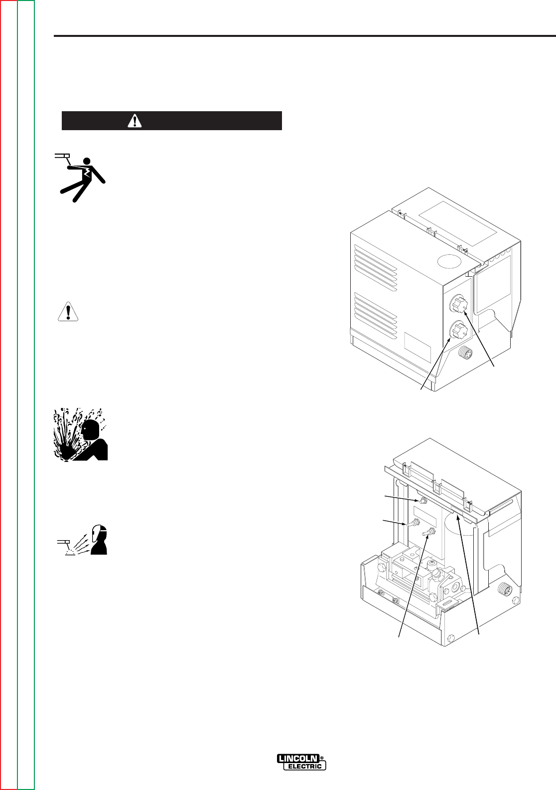
B-2
OPERATION
B-2
CONTROLS AND THEIR
FUNCTIONS
CONSTANT CURRENT CONTROLS
Operator controls for welding using a constant current
power source are illustrated in Figure B.1. Refer to the
figure and the following explanations of the controls.
FIGURE B.1 – CONSTANT CURRENT CONTROLS
LN-8
Read and understand this entire section before
operating your machine.
SAFETY INSTRUCTIONS
ELECTRIC SHOCK can kill.
• Do not touch electrically live parts such
as output terminals or internal wiring.
• Insulate yourself from the work and ground.
• Always wear dry insulating gloves.
____________________________________
FUMES AND GASES
can be dangerous.
• Keep your head out of fumes.
• Use ventilation or exhaust to remove
fumes from breathing zone.
____________________________________
WELDING, CUTTING and
GOUGING SPARKS
can cause fire or explosion
• Keep flammable material away.
• Do not weld, cut or gouge on containers
that have held combustibles.
____________________________________
ARC RAYS
can burn.
• Wear eye, ear and body protection.
____________________________________
Only qualified personnel should operate this equip-
ment. Observe all safety information throughout this
manual.
WARNING
CURRENT
CONTROL
VOLTAGE
CONTROL
CIRCUIT
BREAKER
TRIGGER
INTERLOCK
GROUND LEAD
PROTECTOR
RESET BUTTON
WIRE FEED
DIRECTION
CONTROL
B-3
OPERATION
B-3
CURRENT CONTROL. Adjusts welding current by
controlling power source output.
VOLTAGE CONTROL. Adjusts arc voltage by control-
ling wire feed speed.
TRIGGER INTERLOCK. With the switch in the OFF
position, the wire feed motor runs and the welding cir-
cuit is energized only when the gun trigger is pressed.
The operator must hold the trigger in from the start to
the finish of the weld. To stop the arc, the operator
releases the trigger and raises the gun from the work.
With the switch in the ON position, the operator holds
the trigger until the arc is established, then the trigger
can be released. When the welding is completed, the
operator raises the gun from the work to break the
arc.
WIRE FEED DIRECTION CONTROL. The direction
the electrode passes through the wire feeder is con-
trolled by this switch. The electrode is fed through the
wire feeder in the same direction that the switch is
pointing.
CIRCUIT BREAKER. Protects the circuit from severe
wire feed motor overloads and short circuits. Press to
reset.
GROUND LEAD PROTECTOR RESET BUTTON.
The ground lead protector guards the ground lead in
the control cable from damage that can occur when
the electrode circuit touches the wire feeder frame
while the gun trigger is pressed. This button resets the
ground lead protector circuit.
CONSTANT VOLTAGE CONTROLS
Operator controls for welding using a constant voltage
power source that differ from the constant current con-
trols are illustrated in Figure B.2. Refer to the figure
and the following explanations of the controls.
VOLTAGE CONTROL. Adjusts arc voltage by control-
ling power source output voltage.
CURRENT CONTROL. Adjusts wire feed speed to
control welding current.
FIGURE B.2 – CONSTANT VOLTAGE CONTROLS
LN-8
Return to Section TOC Return to Section TOC Return to Section TOC Return to Section TOC
Return to Master TOC Return to Master TOC Return to Master TOC Return to Master TOC
VOLTAGE
CONTROLS
CURRENT
CONTROLS

B-4
OPERATION
B-4
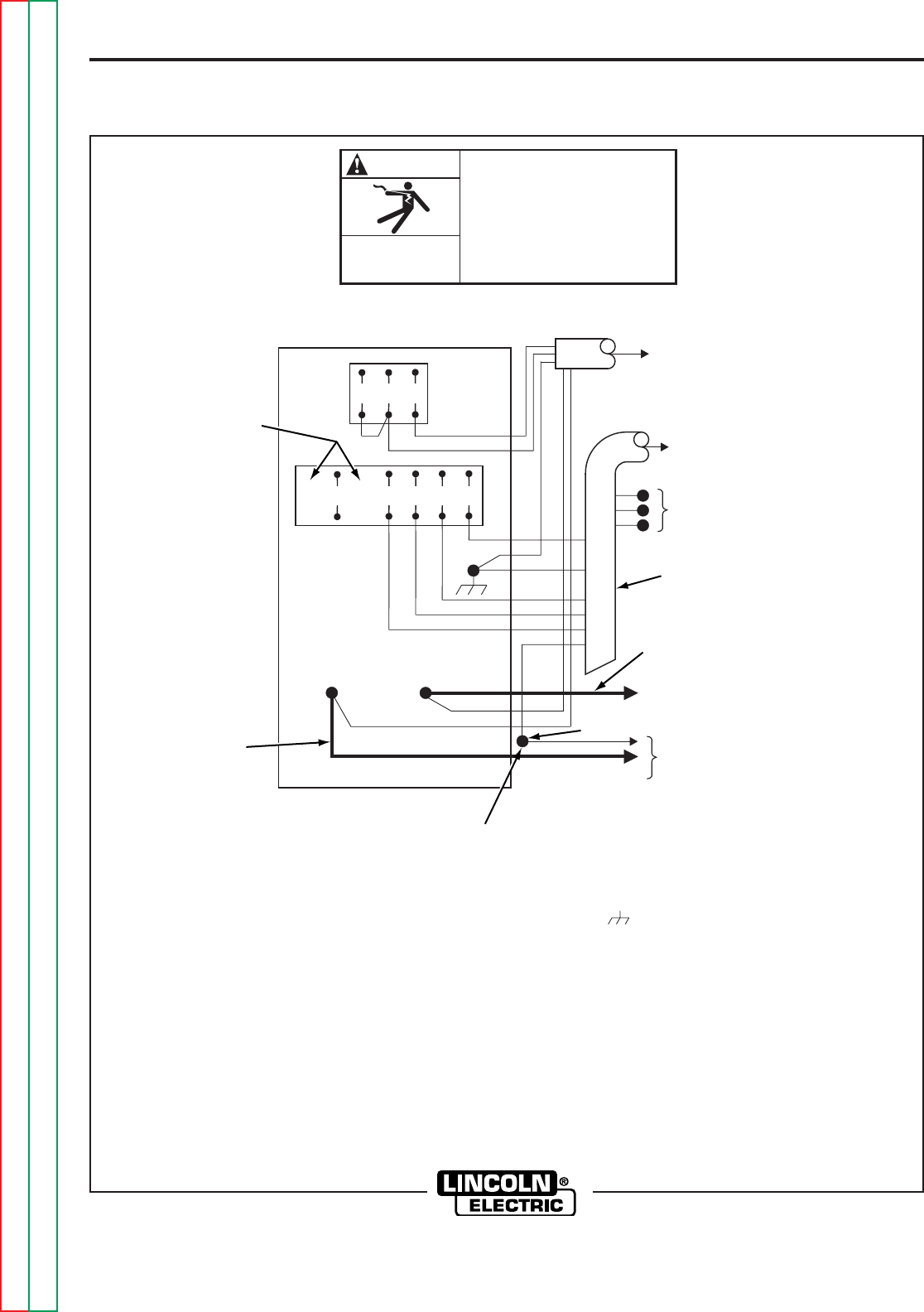
CIRCUIT PROTECTION
FIELD CIRCUIT FUSE. This 1/2 amp slow blow fuse,
located on the Relay PC board, protects the field cir-
cuit. It will blow if the field shorts or if one of the field
circuit components on the Relay PC board fails.
MOTOR THERMAL PROTECTION. The temperature
sensing thermal protector mounted in the motor opens
the relay circuit when the motor overheats because of
excessive loading or frequent triggering. This protects
the motor without nuisance tripping. The thermal pro-
tector automatically resets itself after the motor cools
sufficiently (may take 10-15 minutes). Reset time can
be shortened by cooling the motor with an air hose or
fan.
CIRCUIT BREAKER. The 5 amp circuit breaker locat-
ed above the drive rolls normally trips only when an
overload occurs because of excessive loading in the
wire feed cable, or a defective motor or control com-
ponent. After allowing a minute for cooling, push the
reset button and weld. If it trips again, be sure the wire
feed cable is clean and the proper size for the wire
diameter being fed. If it still trips, look for a defective
electrical component.
AVOIDING GROUND LEAD
PROTECTOR (GLP) ACTIVATION
The frame of the LN-8 wire feed unit and the drive
motor are grounded to the frame of the power source
by a lead in the control cable. An overload protector
prevents welding current from damaging this lead if
the electrode circuit touches the wire feeder frame
while the gun trigger is pressed.
When the protector is tripped, the welding contactor in
the power source will not close when the gun trigger is
pressed.
DO NOT allow the electrode to contact the case of the
wire feeder or the uninsulated part of the wire reel
stand when the gun trigger is activated.
Be sure that all work lead connections to the work
make tight metal-to-metal contact.
DO NOT allow excess input cable or work cable to be
placed closer than three feet from the wire feeder.
DO NOT coil excess input cable assembly or use a
coiled assembly as shipped from the factory. Instead,
loop the excess cable length back and forth in three to
six foot straight lengths. Coiling the input cable results
in a transformer action between the electrode
conductor cable and the ground lead in the
multiconductor control cable. This transformer action
can cause a current to flow in the ground lead which
will falsely activate the GLP circuit.
To reset the GLP circuit, press the white button above
the drive motor and to the right of the circuit breaker.
LN-8
Return to Section TOC Return to Section TOC Return to Section TOC Return to Section TOC
Return to Master TOC Return to Master TOC Return to Master TOC Return to Master TOC
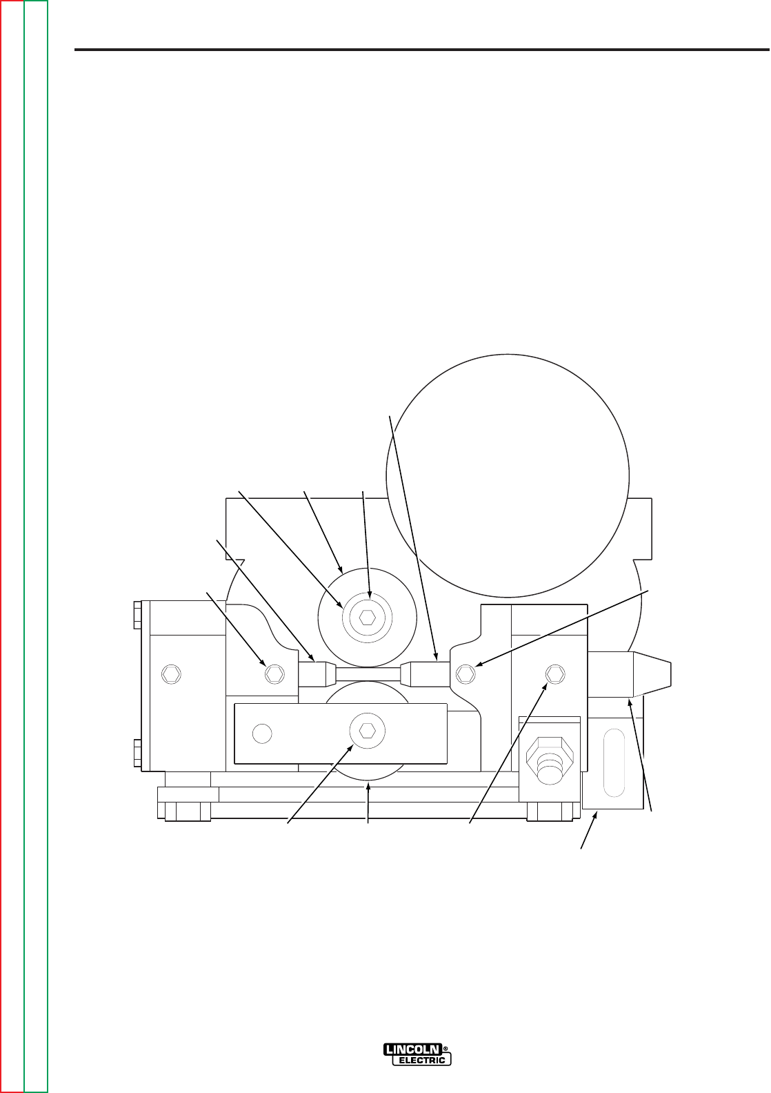
B-5
OPERATION
B-5
WIRE FEED ROLLS AND GUIDE
TUBES
The drive rolls and guide tube kits are ordered sepa-
rately. Refer to Figure B.3 and install these parts per
the following instructions:
1. Loosen the idle roll spring pressure screw.
2. Remove the drive roll screw and clamping collar
from the drive shaft.
3. Install the drive roll and replace the clamping col-
lar. Tighten the drive roll screw.
4. Remove idle roll shaft screw. Install the idle roll
and idle roll shaft screw.
5. Remove the large ingoing guide from the rear
brass block by loosening the locking screw.
6. Loosen the ingoing guide tube clamping screw.
Install the ingoing guide tube (which is stenciled
“in”) through the rear brass block. Tighten the
clamping screw.
LN-8
Return to Section TOC Return to Section TOC Return to Section TOC Return to Section TOC
Return to Master TOC Return to Master TOC Return to Master TOC Return to Master TOC
FIGURE B.3 – WIRE FEED ROLLS AND GUIDE TUBE INSTALLATION
LOCKING
SCREW
OUTGOING
GUIDE TUBE
CLAMPING
COLLAR DRIVE
ROLL
DRIVE
ROLL
SCREW
INGOING
GUIDE
TUBE
CLAMPING
SCREW
LOCKING
SCREW
LARGE
INGOING
GUIDE
IDLE ROLL
SPRING PRESSURE
SCREW
IDLE
ROLL
IDLE ROLL
SHAFT SCREW

B-6
OPERATION
B-6
7. Install the large ingoing guide into the rear brass
block and tighten the locking screw.
8. Install the outgoing guide tube with its plastic
insert through the front brass block. Tighten the
locking screw so the dog point goes into the
groove on the O.D. of the guide tube.
9. Set the drive roll spring pressure:
a. For wire sizes from 0.030 thru 0.052 in. (0.8
thru 1.3 mm) – With wire in the system, the
idle roll pressure indicator should be set to the
wire size shown on the “solid” side of the
nameplate. (For 0.030 in. (0.8 mm) solid wire,
set the pressure indicator to slightly less than
the 0.035 in. (0.9 mm) marking.) This setting
is a starting point and may have to be
changed depending upon the type of wire,
surface condition, lubrication, and hardness.
The optimum idle roll setting can be deter-
mined when there are wire stoppages. If the
wire “bird nests” between the drive roll and
the guide tube, the idle roll spring pressure is
too high. When properly set, the drive rolls will
slip during a stoppage. If the electrode is
removed from the cable, there will be a slight
waviness in the electrode for about a foot
beyond the slip marks on the electrode. If
there is no waviness, the pressure is set too
low.
b. For 1/16 in. (1.6 mm) solid or 0.062 in.
(1.6 mm) cored wire (using the 1/16 in. drive
roll) The idle roll pressure should be set with
wire in the system. For 1/16 in. (1.6 mm)
solid wire, the indicator should be lined up
with the “solid” 1/16 in. mark. For 0.062 in.
(1.6 mm) cored wire, adjust the idle roll pres-
sure so that the indicator is lined up with the
“cored” 3/32 in. mark.
NOTE: These indicator settings are accurate enough
so that there is no need to readjust unless the elec-
trode is unusually soft.
c. For wire sizes from 0.068 thru 0.120 in. (1.7
thru 3.0 mm) Idle roll pressure should be set
with wire in the system. For solid wire, the
indicator should be lined up with the “solid”
wire settings. For cored wire, the indicator
should be lined up with the “cored” wire set-
tings. When using 7/64 in. (2.8 mm) diameter
‘Innershield’ wire, adjust the idle roll pressure
so that the indicator is between the 0.120 and
3/32 in. “cored” wire setting.
NOTE: The indicator settings for these larger wire
sizes are accurate enough so that there is no need to
readjust, unless the electrode is unusually soft.
The drive rolls are stamped with the wire size for
which they are designed. If a wire size is used
that is not stamped on the drive roll, the drive
rolls and guide tubes will have to be changed.
SETTING FOR CV OR CC POWER
SOURCES
The LN-8N and LN-8NE weld only with a constant
voltage (CV) power source. These machines can be
converted for constant current (CC) welding by
installing the proper parts.
The LN-8S and LN-8SE weld with either a CV or CC
power source. Set the equipment for either “CV” or
“CC” as appropriate per the following:
1. If using a multi-process power source, set it up
per the instructions in the operating manual
shipped with the power source.
2. Turn the input power off and open the left panel.
Set the “CV-CC” switch located on the variable
voltage PC board inside the control box as
shown in Figure B.4.
3. There are two nameplates on top of each other
on the front of the wire feeder control box. Make
sure the correct nameplate for the power source
being used is on top.
LN-8
Return to Section TOC Return to Section TOC Return to Section TOC Return to Section TOC
Return to Master TOC Return to Master TOC Return to Master TOC Return to Master TOC
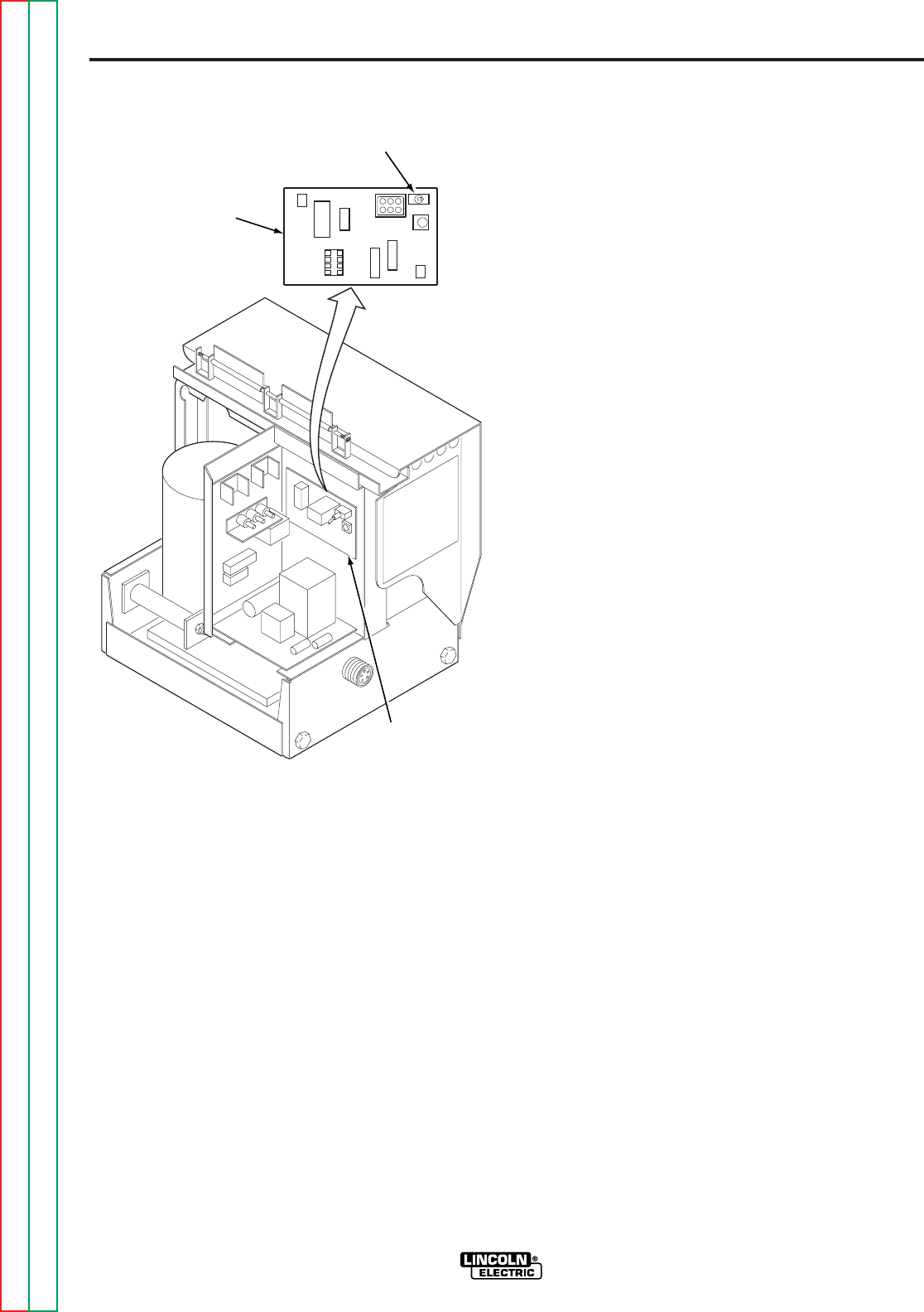
B-7
OPERATION
B-7
FIGURE B.4 – CV-CC SWITCH
WELDING WITH A CONSTANT
VOLTAGE POWER SOURCE
1. Current and voltage adjustments
Amps Control — All Power Sources
Set the welding current (or wire feed speed) with
the LN-8 Amps control.
Volts Control — DC-600 Power Source
a. Set the mode switch on the power source to
CV Innersheild or CV Subarc, as required.
b. Place power source output control toggle
switch in the ‘Output Control Remote’ posi-
tion. Total voltage control is now at the LN–8.
Volts Control — Idealarc R3S Power Sources
Set the power source to the approximate voltage
required, per the R3S instruction manual. Make
final adjustments with the LN–8 ‘Volts’ control (or
the ‘Fine Voltage Control’ on the optional Line
Voltage Compensator).
Volts Control — SAM Power Sources
Set the power source for the approximate voltage
required, per the SAM instruction manual. Make
final adjustments with the LN-8 ‘Volts’ control.
If using the variable inductance control (see SAM
instruction manual), set the SAM ‘Current
Control’ as desired in the 8 o’clock range.
2. Set the ‘Direction of Wire Feed’ switch so the
wire feeds out of the gun.
3. Adjust the electrical stickout and the actual
welding current and voltage as needed.
WELDING WITH A CONSTANT
CURRENT POWER SOURCE
1. Current and voltage adjustments
Volts Control — All Power Sources
Set the welding voltage with the LN-8 ‘Volts’ control.
Amps Control — CC Power Sources
a. Place mode switch in the CC submerged arc
position.
b. Place power source output control toggle
switch in the ‘Output Control Remote’ posi-
tion. Total current control is now at the LN–8.
Amps Control — SAM Power Sources
Set the Current Control on the power source for
the approximate current required. Make final
adjustments with the LN-8 ‘Amps’ control.
2. Set the ‘Direction of Wire Feed’ switch so the
wire feeds out of the gun.
3. Adjust the welding current and voltage while
welding as needed.
LN-8
Return to Section TOC Return to Section TOC Return to Section TOC Return to Section TOC
Return to Master TOC Return to Master TOC Return to Master TOC Return to Master TOC
CV-CC
SWITCH
VARIABLE
VOLTAGE
PC BOARD
VARIABLE
VOLTAGE
PC BOARD
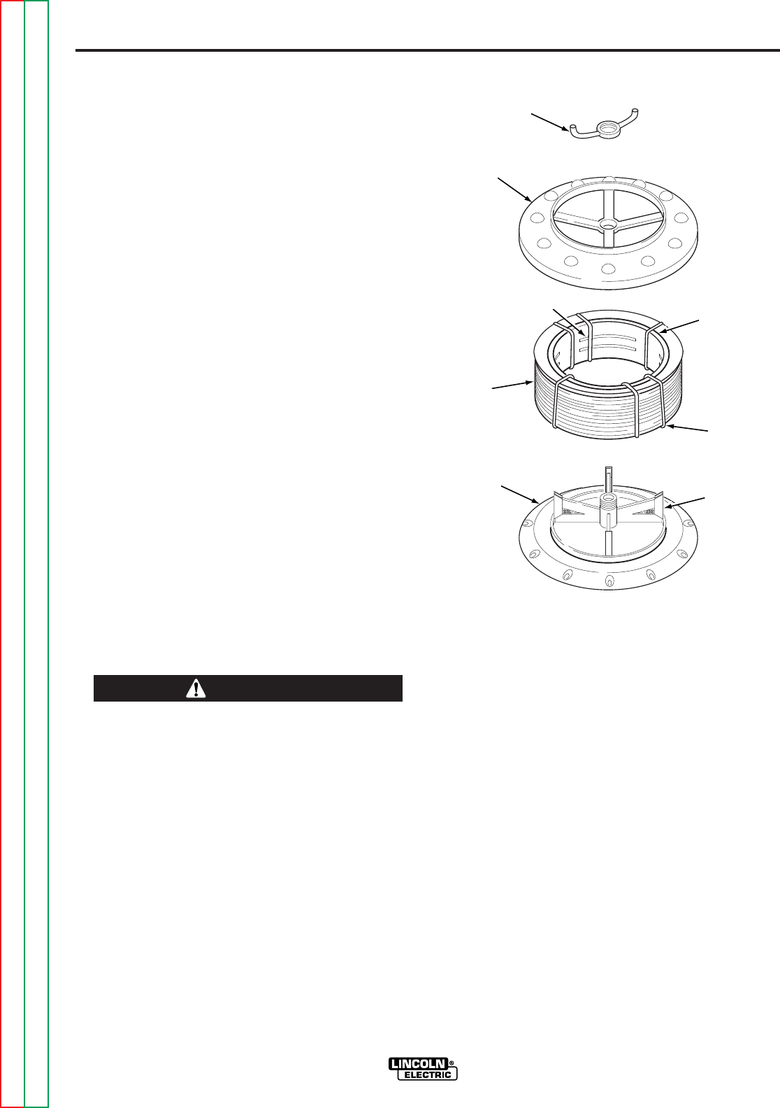
B-8
OPERATION
B-8
WIRE REEL LOADING – 50 AND
60 lb COILS (K303 WIRE REEL
STAND)
MOUNTING A 50 OR 60 lb COIL
1. To remove the wire reel from its shaft, grasp the
spring loaded knob and pull out. This straightens
the knob so it seats into the shaft when released.
Remove the reel.
2. Lay the reel flat on the floor. Loosen the spinner
nut and remove the cover plate. See Figure B.5.
3. Place the coil of electrode on the reel so it
unwinds as the reel rotates clockwise. DO NOT
cut the tie wires at this time.
4. Be sure the coil is placed so the spring loaded
arms will not interfere with the later removal of
the coil tie wires.
5. When loading the electrode, be certain the coil is
placed on the reel so the spring loaded arms are
at the center of the slots in the cardboard coil liner.
This provides the positive compression of the coil
sides needed for trouble-free wire feeding.
6. Put the cover plate on the reel so the four arms
of the cover plate straddle and are in line with the
spring loaded arms of the reel.
7. Tighten the cover as much as possible by hand.
DO NOT hammer on the spinner nut arms.
Always be sure the free end of the coil is securely
held while the tie wires are being cut and until the wire
is feeding through the drive rolls. Failure to do this will
result in “back lashing” of the coil, which may tangle
the wire. A tangled coil will not feed. It must be untan-
gled or discarded.
____________________________________
FIGURE B.5 – LOADING A 50 OR 60 lb COIL
8. Cut and remove only the tie wire holding the free
end of the coil. Insert the free end into one of the
holes in the cover and secure it by bending it
back. Cut and remove the remaining tie wires.
9. Replace the reel on the wire reel stand. Grasp
the shaft knob, pull it out and swing it across the
reel hub, locking the reel in place.
LN-8
Return to Section TOC Return to Section TOC Return to Section TOC Return to Section TOC
Return to Master TOC Return to Master TOC Return to Master TOC Return to Master TOC
SPINNER
NUT
COVER
PLATE
COIL
SLOTS CARDBOARD
COIL
LINER
TIE
WIRE
REEL SPRING
LOADED
ARM
CAUTION
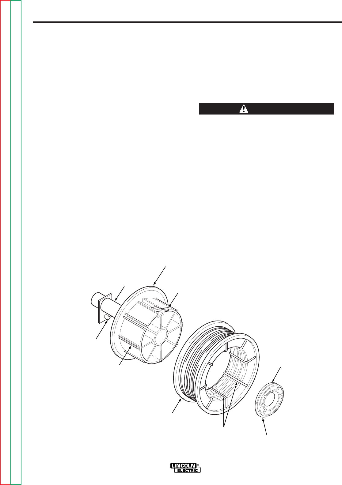
B-9
OPERATION
B-9
WIRE REEL LOADING (K1524-1
UNIVERSAL WIRE REEL STAND)
TO MOUNT A 30 lb (14 kg) READI-REEL
PACKAGE (USING THE MOLDED PLASTIC
K363-P READI-REEL ADAPTER):
The spindle should be located in the LOWER mount-
ing hole.
1. Depress the Release Bar on the Retaining Collar
and remove it from the spindle. See Figure B.6.
2. Place the Adapter on the spindle.
3. Re-install the Retaining Collar. Make sure that
the Release Bar “pops up” and that the collar
retainers fully engage the retaining groove on the
spindle.
4. Rotate the spindle and adapter so the retaining
spring is at the 12 o’clock position.
5. Position the Readi-Reel so that when it rotates
the wire is de-reeled from the bottom of the coil.
6. Set one of the Readi-Reel inside cage wires on
the slot in the retaining spring tab.
7. Lower the Readi-Reel to depress the retaining
spring and align the other inside cage wires with
the grooves in the molded adapter.
8. Slide the cage all the way onto the adapter until
the retaining spring “pops up” fully.
Check to be sure the Retaining Spring has fully returned
to the locking position and has SECURELY locked the
Readi-Reel cage in place. The Retaining Spring must
rest on the cage, not the welding electrode.
____________________________________
9. To remove the Readi-Reel from the Adapter,
depress the retaining spring tab with a thumb
while pulling the Readi-Reel cage from the molded
adapter with both hands. Do not remove the
Adapter from the spindle.
LN-8
Return to Section TOC Return to Section TOC Return to Section TOC Return to Section TOC
Return to Master TOC Return to Master TOC Return to Master TOC Return to Master TOC
CAUTION
BRAKE
HOLDING
PIN
GROOVES
READI-REEL
INSIDE CAGE
WIRES RELEASE
BAR
RETAINING
COLLAR
RETAINING
SPRING
2 IN. O.D.
SPINDLE
ADAPTER
FIGURE B.6 – READI-REEL MOUNTING
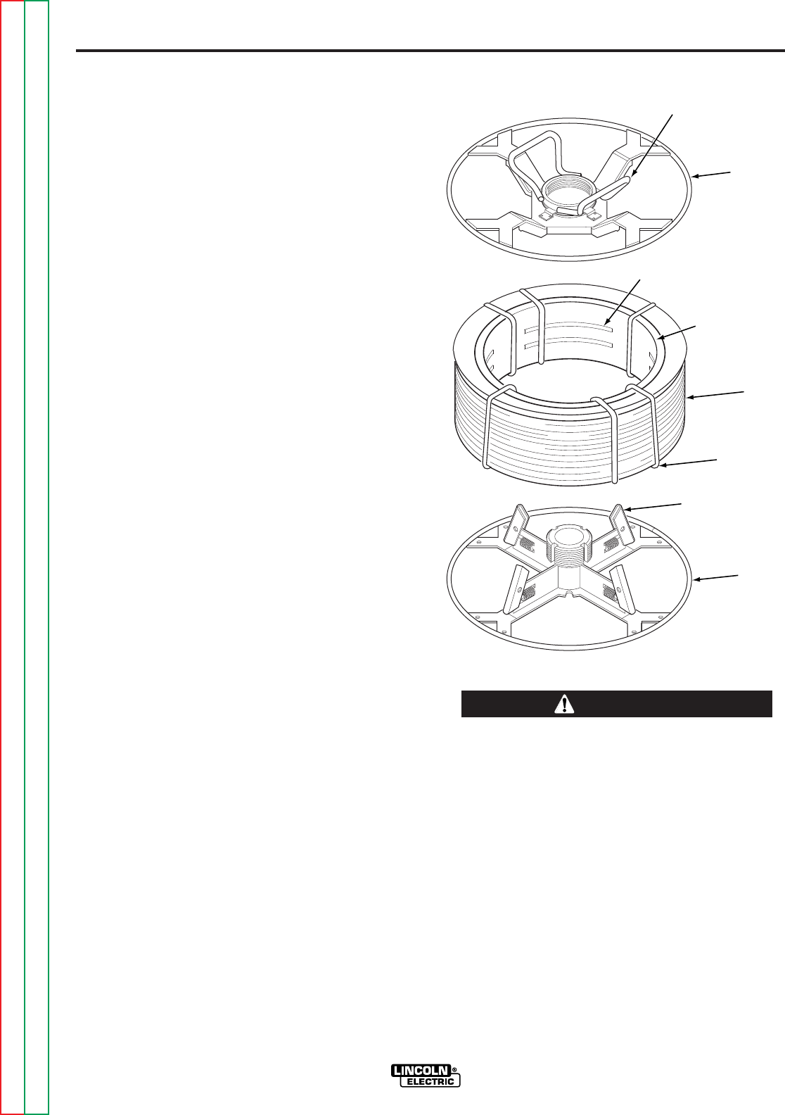
B-10
OPERATION
B-10
TO MOUNT 10 TO 44 lb (4.5 to 20 kg) SPOOLS
(12 in./300 mm DIAMETER) OR 14 lb (6 kg)
INNERSHIELD COILS:
The spindle should be located in the lower mounting
hole.
[For 8 in. (200 mm) spools, a K468 spindle adapter
must first be slipped onto the spindle.]
[For 13 to 14 lb (6 kg) Innershield coils, a K435 Coil
Adapter must be used.]
1. Depress the Release Bar on the Retaining Collar
and remove it from the spindle.
2. Place the spool on the spindle, making certain
the spindle brake pin enters one of the holes in
the backside of the spool. Be certain the wire
comes off the reel in a direction so as to de-reel
from the bottom of the coil.
3. Re-install the Retaining Collar. Make sure that
the Release Bar “pops up” and that the collar
retainers fully engage the retaining groove on the
spindle.
TO MOUNT A 50 to 60 lb (22.7 to 27.2 kg) COIL:
(USING K1504-1 COIL REEL) (FOR 50 to 60 lb
READI-REELS A K438 READI-REEL ADAPTER
MUST BE USED.)
The spindle should be located in the UPPER mount-
ing hole.
1. With the K-1504-1 Coil Reel mounted on the 2 in.
(51 mm) spindle (or with reel laying flat on the
floor) loosen the spinner nut and remove the reel
cover. See Figure B.7.
2. Before cutting the tie wires, place the coil of elec-
trode on the reel so it unwinds from the bottom
as the reel rotates.
3. Tighten the spinner nut against the reel cover as
much as possible by hand, using the reel cover
spokes for leverage. DO NOT hammer on the
spinner nut arms.
4. Cut and remove only the tie wire holding the free
end of the coil. Hook the free end around the rim
of the reel cover and wrap it around to secure.
Cut and remove the retaining tie wires.
FIGURE B.7 – K1504-1 COIL REEL
Always be sure the free end of the coil is securely
held while the tie wires are being cut and until the wire
is feeding through the drive rolls. Failure to do this will
result in “backlash” of the coil, which may tangle the
wire. A tangled coil will not feed, so it must either be
untangled or discarded.
____________________________________
5. Be sure the coil is engaged with the spindle
brake pin and the Release Bar and Retaining
Collar “pops up” and that the collar retainers fully
engage the retaining groove on the spindle.
LN-8
Return to Section TOC Return to Section TOC Return to Section TOC Return to Section TOC
Return to Master TOC Return to Master TOC Return to Master TOC Return to Master TOC
SPINNER NUT
COVER
PLATE
SLOTS
CARDBOAR
D
COIL LINER
COIL
TIE WIRE
SPRING
LOADED ARM
REEL
CAUTION
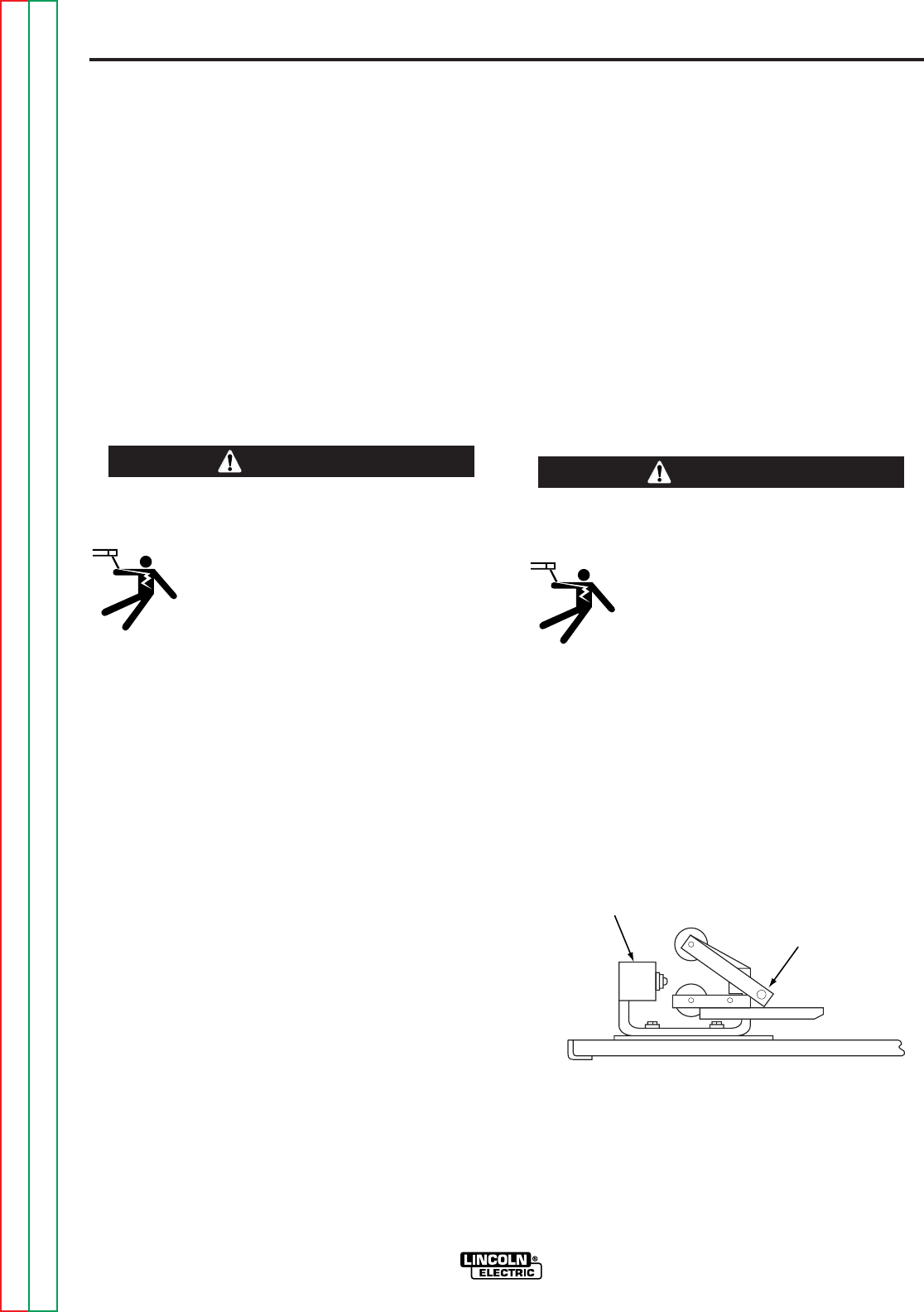
B-11
OPERATION
B-11
FEEDING ELECTRODE TO THE LN-8N OR
LN-8S
1. Turn the reel until the free end of the electrode is
accessible.
2. While tightly holding the electrode, cut off the
bent end and straighten the first six inches. Cut
off the first inch. (If the electrode is not properly
straightened, it may not feed or may not go into
the outgoing guide tube causing a “birdnest”.)
3. Insert the free end through the incoming guide
tube.
4. Press the gun trigger and push the electrode into
the drive roll.
ELECTRIC SHOCK can kill.
• Do not touch electrically live parts such
as output terminals or internal wiring.
• When inching with the gun trigger,
electrode and drive mechanism are
“hot” to work and ground.
____________________________________
5. Inch the electrode through the gun.
FEEDING ELECTRODE TO THE LN-8NE
OR LN-8SE (WITH EXTENSION)
1. Slide the ingoing guide tube of the hand crank to
the forward position.
2. Remove start end of coil from the hole in the wire
reel cover, straighten the first six inches of the
wire and then insert this end into the ingoing
guide tube. Push at least one foot of wire
through.
3. Pull the ingoing guide tube back to the rear posi-
tion and rotate 90˚ so that it will remain in this
position during the cranking operation.
4. Pull the plastic hand crank handle to the out posi-
tion in the arm.
5. Pull the shaft and drive roll assembly to the out
position.
6. Apply downward pressure to the idler roll pres-
sure arm. Maintain this pressure and start crank-
ing the wire thru the system. Keep the conductor
cable as straight as possible during the loading
operation. This will facilitate cranking the wire
through.
7. Crank until the wire touches the drive roll and
then pull the gun trigger. This will start the drive
rolls and feed the wire the rest of the way
through the cable and gun assembly.
ELECTRIC SHOCK can kill.
• Do not touch electrically live parts such
as output terminals or internal wiring.
• When inching with the gun trigger,
electrode and drive mechanism are
“hot” to work and ground.
____________________________________
8. Push the plastic of the hand crank to the in
position, as shown in Figure B-8.
9. Shift the ingoing guide tube to the forward
position.
FIGURE B.8 – HAND CRANK POSITION
LN-8
Return to Section TOC Return to Section TOC Return to Section TOC Return to Section TOC
Return to Master TOC Return to Master TOC Return to Master TOC Return to Master TOC
WARNING WARNING
BRASS
BLOCKS HAND CRANK
ARM

B-12
OPERATION
B-12
SLOW ACCELERATION STARTING
(CODE 7926 AND ABOVE)
The LN-8 has the capability of optimum starting for dif-
ferent processes. This is accomplished by designing
the LN-8 to start with two different speeds of con-
trolled acceleration. As shipped, the unit is connected
for fast acceleration, which is best for most open arc
procedures. The slower acceleration may be more
desirable for long stickout applications and most sub-
merged arc procedures. If the electrode being used
does not give satisfactory starting because of “stub-
bing” or “blast off”, the slower acceleration can be
obtained by modifying the LN-8 as follows:
1. Turn off the control power to the LN-8 at the
power source.
2. Remove the screws holding the control section
cover in place and swing open.
3. Switch circuit #1 of S1 on the Control PC board
from position “F” to position “S”.
4. Reassemble.
FLUX TANK LOADING
Either turn off the incoming air line or remove the
quick disconnect if one has been installed. Slightly
loosen the tank cap and let the air in the tank escape
in the holes in the side of the cap. After pressure has
been released, remove the cap from the tank. Using
the funnel provided, put 100 pounds of flux in the tank.
It is very important that only new or properly reclaimed
flux be put in the tank. Coarse particles and/or mag-
netic particles will stop the flux feeding process. New
Lincoln flux is properly screened at the factory. All
reclaimed flux must be separately screened through a
vibrating screen with 0.065 to 0.075 in. openings and
be put through a magnetic separator. The K310 vibrat-
ed screen and K58 magnetic separator are available
for this purpose. The screen in the funnel supplied
with the tank has much larger openings and its only
purpose is to keep paper and slag out of the tank.
Screw the tank cap back on and tighten hand tight.
Reconnect the incoming air supply.
There will always be a small amount of air and possi-
bly drops of water coming out of the end of the tube
coiled under the tank. This is an automatic disposal
system in case the plant air has water and dirt in it.
LN-8
Return to Section TOC Return to Section TOC Return to Section TOC Return to Section TOC
Return to Master TOC Return to Master TOC Return to Master TOC Return to Master TOC

Return to Master TOC Return to Master TOC Return to Master TOC Return to Master TOC
SECTION C-1
ACCESSORIES
SECTION C-1
LN-8
TABLE OF CONTENTS
-ACCESSORIES SECTION-
Accessories............................................................................................................................. Section C
General................................................................................................................................ C-2
K163 Undercarriage (Requires K303, K377, or K378) .................................................. C-3
K178 Mounting Platform................................................................................................ C-3
K261 Meter Kit............................................................................................................... C-3
K202 Burnback Kit......................................................................................................... C-3
K58 Magnetic Separator ............................................................................................... C-3
K119 Gravity Feed Flux Cone ....................................................................................... C-3
K310 Flux Screen.......................................................................................................... C-3
K320 Flux Tank ............................................................................................................. C-3
K161 Mechanized Travel Power Pack........................................................................... C-3
K240 Contactor Kit ........................................................................................................ C-4
K317 Dual Process Kit (No Polarity Change) ................................................................ C-4
K318 Dual Process Contactor Kit (With Polarity Changes) ........................................... C-4
Reel Mounting Accessories................................................................................................. C-4
K303 50 to 60 lb (22.7 to 27.2 kg) Wire Reel Stand...................................................... C-4
K1524-1 Universal Reel Stand and Base Assembly ..................................................... C-4
K162 Spindle for Mounting Readi-Reels and 10 thru 30 lb
(4.5 thru 13.5 kg) Spools ............................................................................................ C-4
K377 Small Mounting Stand for Readi-Reel Coils or 10 thru 30 lb
(4.5 thru 13.5 kg) Spools with 2 in. (50 mm) I.D ......................................................... C-4
K378 Small Mounting Stand for 13 to 14 lb (6.0 to 6.4 kg) Innershield Coils ................ C-4
M11514 Wire Reel Dust Shield Door for K303 .............................................................. C-4
Welding Guns...................................................................................................................... C-5
Innershield Guns ........................................................................................................... C-5
Submerged Arc Guns.................................................................................................... C-5
GMAW Guns ................................................................................................................. C-5
Welding Gun Accessories ................................................................................................... C-5
K70 Fillet Guide............................................................................................................. C-5
K110 Hand Travel Unit .................................................................................................. C-5
K62 Squirtmobile ........................................................................................................... C-5
Constant Current Conversion Parts .................................................................................... C-5

Product Number Name
K163 UNDERCARRIAGE
K178 MOUNTING PLATFORM
K261 METER KIT
K202 BURNBACK KIT
K58 MAGNETIC SEPARATOR
K119 GRAVITY FEED FLUX CONE
K310 FLUX SCREEN
K320 FLUX TANK
K161 MECHANIZED TRAVEL POWER PACK
K240 CONTACTOR KIT
K317 DUAL PROCESS KIT (NO POLARITY CHANGE)
K318 DUAL PROCESS CONTACTOR KIT (WITH POLARITY CHANGES)
K303 50 THRU 60 lb (22.7 THRU 27.2 kg) WIRE REEL STAND
K1524-1 UNIVERSAL REEL STAND AND BASE ASSEMBLY
K162 SPINDLE FOR MOUNTING READI-REELS AND 10 THRU 30 lb
(4.5 THRU 13.5 kg) SPOOLS
K377 SMALL MOUNTING STAND FOR READI-REEL COILS OR 10 THRU 30 lb
(4.5 THRU 13.5 kg) SPOOLS WITH 2 in. (50 mm) I.D.
K378 SMALL MOUNTING STAND FOR 13-14 lb. (6.0-6.4 kg) INNERSHIELD COILS
M11514 WIRE REEL DUST SHIELD DOOR FOR K303
K112 SUBMERGED ARC WELDING GUN - 500 AMPS
K113 SUBMERGED ARC WELDING GUN - 600 AMPS
K114 SUBMERGED ARC WELDING GUN - 600 AMPS
K115 INNERSHIELD WELDING GUN - 450 AMPS
K116 INNERSHIELD WELDING GUN - 400 AMPS
K126 INNERSHIELD WELDING GUN - 350 AMPS
K497 MAGNUM GMA WELDING GUN - 200 AMPS
K471 MAGNUM GMA WELDING GUN - 300 AMPS
K527 MAGNUM GMA WELDING GUN - 400 AMPS
K70 FILLET GUIDE
K110 HAND TRAVEL UNIT
K62 SQUIRTMOBILE
CONSTANT CURRENT CONVERSION PARTS
C-2
ACCESSORIES
C-2
GENERAL
The following is a list of the accessories that can be
used with the LN-8 wire feeder unit. A detailed description of each item is given later in the
section.
LN-8
Return to Section TOC Return to Section TOC Return to Section TOC Return to Section TOC
Return to Master TOC Return to Master TOC Return to Master TOC Return to Master TOC
TABLE C.1 – LN-8 WIRE FEEDER ACCESSORIES

C-3
ACCESSORIES
C-3
K163 UNDERCARRIAGE
(REQUIRES K303, K377, OR K378)
The undercarriage includes casters, wheels, a handle,
and related hardware. Casters are mounted at the
front and wheels are mounted at the rear of the plat-
form. The handle is bolted to the front of the platform
so the wire feeder can be tilted back and wheeled like
a two-wheel truck. Installation sheet M13424 is provid-
ed with the undercarriage.
K178 MOUNTING PLATFORM
This is a turntable type platform for mounting the LN-8
to the top of Idealarc power sources. Bolt the platform
to the lift bail per the instructions supplied with the
platform.
K261 METER KIT
All LN-8 wire feed units with code no. 7580 to 7925
come equipped with a factory calibrated Speedmeter
Trimmer PC board and meter kit receptacle prepared
to accept the optional K261 speed-ammeter voltmeter
(analog) kit. LN-8 wire feed units no. 7926 and above
come with the speedmeter trimmers incorporated into
the Control PC board.
K202 BURNBACK KIT
This kit is useful to help prevent the electrode from
sticking in the crater at the end of the weld in two
types of welding applications:
1. Welding with small diameter wire [0.035 thru 1/16
in. (0.9 thru 1.6 mm)] at fast wire feed speed
when there is a tendency to overrun the wire.
2. When the semiautomatic gun is mounted in a fix-
ture or on the K62 Squirtmobile in such a manner
that it cannot be lifted from the work at the end of
the weld.
The kit delays the dropout of the contactor allowing
the electrode to burnback from the crater at the end of
the weld. The delay time is adjustable for optimum
burnback for different sizes, processes, and proce-
dures. Installation instructions are shipped with the kit.
K58 MAGNETIC SEPARATOR
Useful with any submerged arc equipment. The unit
removes foreign magnetic particles from reused sub-
merged arc welding flux. Operating instructions are
included with the kit.
K119 GRAVITY FEED FLUX CONE
The flux cone is manual feed attachment for the K112
and K113 sub-arc guns that is used instead of the
continuous feed flux system. The flux cone attaches to
the gun using the screws provided. The cone also
includes a new clamp to be used to hold the trigger
pod to the gun. Use it in place of the clamp shipped
with the gun.
K310 FLUX SCREEN
The unit was designed to fit the top of either the stan-
dard fill funnel or the K58 magnetic separator. The
unit has a steel screen with 0.065 to 0.075 in. open-
ings and an air vibrator attached to the frame. The
vibrator can be used with air line pressures ranging
from 20 through 100 psi.
For ease of handling, the user should connect the
incoming air line to the 1/8 in. pipe elbow with the aid
of a quick disconnect type air coupling.
It is very important that reclaimed flux to be used in
the continuous flux feeding system be passed through
the K310 screen or its equivalent.
K320 FLUX TANK
The flux tank is available to permit the LN-8 to be
used for submerged arc welding. Installation instruc-
tions are shipped with the kit.
K161 MECHANIZED TRAVEL
POWER PACK
The power pack supplies the power needed by the
K110 hand travel unit or the K62 Squirtmobile when
used with the K114 sub-arc welding gun. Complete
installation instructions are shipped with the kit.
LN-8
Return to Section TOC Return to Section TOC Return to Section TOC Return to Section TOC
Return to Master TOC Return to Master TOC Return to Master TOC Return to Master TOC

C-4
ACCESSORIES
C-4
K240 CONTACTOR KIT
Output contactor with pilot relay to make the electrode
‘cold’ when not welding. Must be ordered when using
the LN-8 with SA-750, SAE, TM, R3M and R3R
Idealarcs. Contactor kits are rated at 600 amps maxi-
mum, and cannot be paralleled with each other.
K317 DUAL PROCESS KIT
(NO POLARITY CHANGE)
The Dual Process Kit is a transfer device that con-
nects two wire feeders to a single power source and
enables each wire feeder to weld a different proce-
dure without changing any of the dials. When used
with the DC-600, the wire feeders can be set for differ-
ent modes; CV Innershield or CV Submerged Arc.
Both wire feeders will operate at the same polarity.
K318 DUAL PROCESS CONTACTOR KIT
(WITH POLARITY CHANGES)
The Dual Process Contactor Kit permits the connec-
tion of two wire feeders to a single power source and
enables each wire feeder to weld at a different proce-
dure and polarity without changing any dials or switch-
es. When used with the DC-600, the wire feeders can
be set for different modes; CV Innershield or CV
Submerged Arc. The kit can also be connected to
operate with the same polarity on each wire feeder.
REEL MOUNTING ACCESSORIES
K303 50 TO 60 lb (22.7 TO 27.2 kg)
WIRE REEL STAND
This assembly includes a framework to which is
attached a 50 to 60 lb (22.7 to 27.2 kg) wire reel, a
mounting spindle, a lift bail, and a cable clamp for fas-
tening the input cable assembly.
K1524-1 UNIVERSAL REEL STAND
AND BASE ASSEMBLY
The wire reel stand comes with a 2 in. spindle. With
the addition of the proper spindle and Readi-Reel
adapters, it can accomodate various sizes of coils,
spools, and Readi-Reels.
K363P 30 lb Readi-Reel Adapter
K435 Spindle Adapter for 14 lb coils
K468 Spindle Kit
K1504-1 60 lb Wire Reel
K438 60 lb Readi-Reel Adapter
K162 SPINDLE FOR MOUNTING
READI-REELS AND 10 THRU 30 lb
(4.5 THRU 13.5 kg) SPOOLS
For use with the K303 wire reel stand. To mount this
spindle kit, remove the shaft from the standard 50 to
60 lb (22.5 to 27.2 kg) wire coils from the mounting
framework. Install the spindle per the instructions
shipped with the kit.
K377 SMALL MOUNTING STAND FOR
READI-REEL COILS OR 10 THRU 30 lb
(4.5 THRU 13.5 kg) SPOOLS WITH 2 in.
(50 mm) I.D.
This assembly includes a wire reel spindle (similar to
the K162 spindle) attached to a small frame. The unit
is supplied with the K363 Readi-Reel Adapter for
using the Lincoln “Readi-Reel Electrode Coils”.
Without the adapter, the unit is capable of handling
spools with a 2 in. I.D., a 12 in. maximum O.D., and a
4 in. width. The spindle has an adjustable breaking
system.
K378 SMALL MOUNTING STAND FOR
13 TO 14 lb (6.0 TO 6.4 kg)
INNERSHIELD COILS
This assembly includes the smaller frame as used in
the K377 and the fully enclosed canister system for
derailing of the 14 lb coil. This system has a fixed
brake for the 14 lb coil.
M11514 WIRE REEL DUST SHIELD DOOR
FOR K303
In extremely dusty and dirty locations, this door kit can
be added to those units having a dust shield kit
(S14543). This door kit includes a hinged door and
sliding bottom seal. When these parts are attached to
the reel support per the instructions included, the unit
becomes a completely enclosed housing. Order part
no. M11514.
LN-8
Return to Section TOC Return to Section TOC Return to Section TOC Return to Section TOC
Return to Master TOC Return to Master TOC Return to Master TOC Return to Master TOC

C-5
ACCESSORIES
C-5
WELDING GUNS
INNERSHIELD GUNS
The K126 gun and cable assembly is recommended
for most Innershield electrodes at up to 350 amps.
The K115 gun and cable assembly is recommended
for up to 450 amps.
The K116 gun and cable assembly is recommended
for up to 600 amps.
NOTE: LinconditionerTM guns are recommended for
locations where smoke accumulation is a problem and
conventional exhaust systems are ineffective. The
available smoke removal type Innershield guns and
vacuum units can be used in these locations.
Instructions are shipped with the equipment.
SUBMERGED ARC GUNS
The K112 gun and cable assembly is recommended
for welding up to 500 amps.
The K113 gun and cable is recommended for use up
to 600 amps.
The K114 gun and cable assembly is a 600 amp gun
that includes a flux valve and receptacle for the K110
or K62.
GMAW GUNS
An expanding line of Magnum GMA gun and cable
assemblies are available to allow welding with solid
and cored electrodes using the GMAW process. See
the appropriate Magnum literature for descriptions of
the 100-500 ampere air cooled gun and cables that
are available. Gun cable lengths range from 10 to
25 ft. (3.0 to 7.5 m) and feed electrode sizes 0.023 to
3/32 in. (0.6 to 2.4 mm).
NOTE: Magnum GMA welding guns require a K466-1
connector for use with an LN-8 wire feeder.
WELDING GUN ACCESSORIES
K70 FILLET GUIDE
The fillet guide is designed to help guide the K114
sub-arc gun so the operator can make more uniform
horizontal fillet welds with less effort. It consists of a
vertical plate roller guide and rear wheel assembly.
Once the roller guide and rear wheel are adjusted, the
weld is easily made by gently pushing the gun into the
fillet. The operator does not have to constantly control
the drag of the flux cone against the vertical plate or
carefully watch the angle of the gun.
K110 HAND TRAVEL UNIT
The mechanized travel unit can be attached to the
K114 sub-arc gun and is used to obtain controlled
travel speeds ranging from 7 to 60 inches. Since the
hand travel unit derives its control power from a mag-
amp source, a K161 power pack is required for this
mode of operation.
K62 SQUIRTMOBILE
The Squirtmobile is a self-propelled trackless carriage
that carries the K114 sub-arc gun on long welds for
automatic welder economy without high fixture costs.
To use the LN-8S or LN-8SE with the Squirtmobile,
install the K161 mechanized travel power pack.
CONSTANT CURRENT
CONVERSION PARTS
To convert the LN-8N or LN-8NE for welding with a
constant current power source, purchase a variable
voltage PC board L5039, and constant current dial
plate (M12230 for LN-8N and LN-8S models, M13148
for LN-8F models above code 7580).
LN-8
Return to Section TOC Return to Section TOC Return to Section TOC Return to Section TOC
Return to Master TOC Return to Master TOC Return to Master TOC Return to Master TOC


Return to Master TOC Return to Master TOC Return to Master TOC Return to Master TOC
SECTION D-1
MAINTENANCE
SECTION D-1
LN-8
TABLE OF CONTENTS
-MAINTENANCE SECTION-
Maintenance. . . . . . . . . . . . . . . . . . . . . . . . . . . . . . . . . . . . . . . . . . . . . . . . . . . . . . . . . . . . . . Section D
Routine Maintenance . . . . . . . . . . . . . . . . . . . . . . . . . . . . . . . . . . . . . . . . . . . . . . . . . . . . . D-2
Drive Rolls and Guide Tubes . . . . . . . . . . . . . . . . . . . . . . . . . . . . . . . . . . . . . . . . . . . . D-2
Wire Reel Mounting . . . . . . . . . . . . . . . . . . . . . . . . . . . . . . . . . . . . . . . . . . . . . . . . . . . D-2
Periodic Maintenance. . . . . . . . . . . . . . . . . . . . . . . . . . . . . . . . . . . . . . . . . . . . . . . . . . . . . D-2
Control Box. . . . . . . . . . . . . . . . . . . . . . . . . . . . . . . . . . . . . . . . . . . . . . . . . . . . . . . . . . D-2
Wire Drive Motor and Gearbox. . . . . . . . . . . . . . . . . . . . . . . . . . . . . . . . . . . . . . . . . . . D-2
Gun and Cable Maintenance . . . . . . . . . . . . . . . . . . . . . . . . . . . . . . . . . . . . . . . . . . . . D-2

D-2
MAINTENANCE
D-2
ROUTINE MAINTENANCE
DRIVE ROLLS AND GUIDE TUBES
After feeding every coil of wire, inspect the drive roll
section. Clean the assembly as necessary. Do not use
solvent to clean the drive roll assembly as it may wash
the lubricant out of the bearings. The drive rolls and
guide tubes are stamped with the wire sizes they will
feed. If a wire size other than that stamped on the rolls
is to be used, the rolls and guide tubes must be
changed.
The drive rolls for 0.068 and 0.120 in. (1.7 thru
3.0 mm) wire have a double set of teeth so they can
be reversed for additional life. Between the two
knurled rolls is a shim washer which limits the damage
to the electrode if wire feeding problems occur. Drive
rolls for 1/16 in. (1.6 mm) and smaller wire have no
teeth and are not reversible.
Refer to the instructions included with the drive roll kit
for installation and replacement of the drive rolls on
the wire feeder.
WIRE REEL MOUNTING
To prolong the life of the reel shaft on the 50 to 60 lb
coils, periodically coat it with a thin layer of grease. No
maintenance to the two position brake is required. If
the brake shoe wears through to metal, replace the
brake assembly.
PERIODIC MAINTENANCE
CONTROL BOX
Every six months, open and inspect the control sec-
tion. The accumulated dirt should be gently blown off
all the electrical components. Be sure the air that is
used is dry. Check all relay contacts.
WIRE DRIVE MOTOR AND GEARBOX
Every year, inspect the gearbox and coat the gear
teeth with a moly-disulfide filled grease. Do not use
graphite grease.
Every six months, check the motor brushes. Replace
them if they are less than 1/4 in. (6.4 mm) long.
GUN AND CABLE MAINTENANCE
For instructions on periodic maintenance for the weld-
ing gun and cables, refer to the manual for your spe-
cific model of welding gun.
LN-8
Return to Section TOC Return to Section TOC Return to Section TOC Return to Section TOC
Return to Master TOC Return to Master TOC Return to Master TOC Return to Master TOC

Return to Master TOC Return to Master TOC Return to Master TOC Return to Master TOC
SECTION E-1
THEORY OF OPERATION
SECTION E-1
LN-8
TABLE OF CONTENTS
-THEORY OF OPERATION SECTION-
Theory of Operation . . . . . . . . . . . . . . . . . . . . . . . . . . . . . . . . . . . . . . . . . . . . . . . . . . . . . . . Section E
General Description . . . . . . . . . . . . . . . . . . . . . . . . . . . . . . . . . . . . . . . . . . . . . . . . . . . . . . E-2
Power Input Circuits . . . . . . . . . . . . . . . . . . . . . . . . . . . . . . . . . . . . . . . . . . . . . . . . . . . . . . E-2
Gun Trigger and 1CR Relay Contact Control Circuits . . . . . . . . . . . . . . . . . . . . . . . . . . . . E-3
Variable Voltage Board, Meter Shunt, Wire Speed and Remote Output Controls . . . . . . . E-4
SCR Operation. . . . . . . . . . . . . . . . . . . . . . . . . . . . . . . . . . . . . . . . . . . . . . . . . . . . . . . . . . E-5
E-2
THEORY OF OPERATION
E-2
GENERAL DESCRIPTION
The LN-8 is a semiautomatic wire feeder
designed for Innershield (FCAW) and
gas metal arc processes with the appro-
priate accessories. It is also suitable for
constant voltage (CV) submerged arc
welding processes. With the optional
variable voltage board installed the LN-8
can be used with constant current (CC)
procedures. The wire feed speed and
welding power source output can be
controlled from the LN-8.
POWER INPUT CIRCUITS
The 115VAC is applied (usually from the
welding power source) via the input
receptacle, through the circuit breaker
and 2 ohm resistor to the control board,
the relay board, and the trigger trans-
former.
The 24VAC developed at the trigger
transformer is rectified on the relay
board and applied to the gun trigger cir-
cuit which controls the 1CR relay.
The 115VAC that is applied to the con-
trol board is rectified and controlled by
SCRs (See SCR Operation) and
applied to the armature of the wire feed
motor.
The relay board rectifies the 115VAC
and applies it to the field winding of the
wire feed motor.
FIGURE E.1 – POWER INPUT CIRCUITS
LN-8
REMOTE
OUTPUT
CONTROL
ELECTRODE
METER
SHUNT
WIRE
FEED
MOTOR
CIRCUIT
BREAKER
INPUT
RECEPTACLE
VARIABLE VOLTAGE
BOARD
CONTROL
BOARD
WIRE FEED
SPEED CONTROL
THERMAL
CIRCUIT
BREAKER
RELAY
BOARD
GLP REED
SWITCH TRIGGER
TRANS.
WIRE
FEED
SWITCH
INTERLOCK
SWITCH
FUSE
GUN
CABLE
RECEPTACLE
FIELD
ARMATURE
#3
2
A
OPTIONAL
BURNBACK
BOARD
CONTROL
#2
&
#4
C
O
N
T
A
C
T
O
R
#531
#31
2 OHMS
#32 #32A
#75
#76
#77
#21 #567
NOTE: Unshaded areas of block logic diagrams are the subject of discussion.
Return to Section TOC Return to Section TOC Return to Section TOC Return to Section TOC
Return to Master TOC Return to Master TOC Return to Master TOC Return to Master TOC
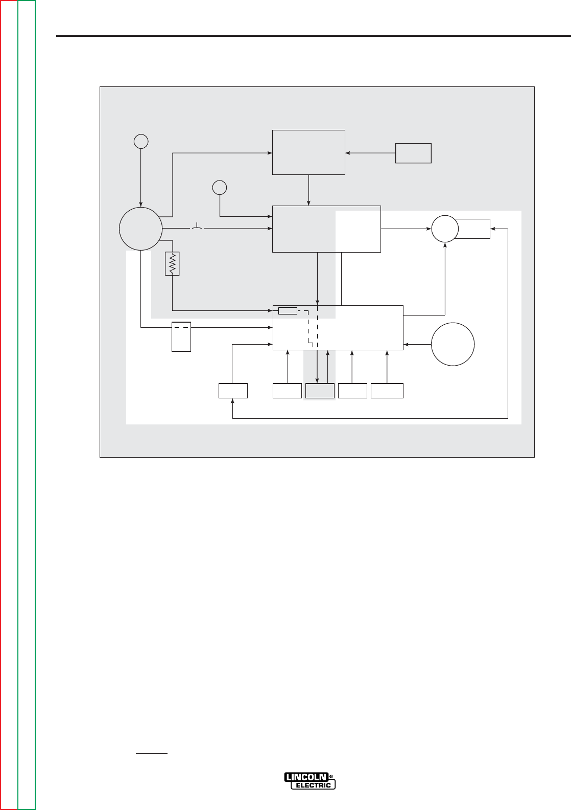
E-3
THEORY OF OPERATION
E-3
GUN TRIGGER AND 1CR
RELAY CONTACT
CONTROL CIRCUITS
When the gun trigger switch is activat-
ed (closed) the 1CR relay is energized.
Three sets of isolated contacts incor-
porated within the 1CR relay perform
several functions. One set of contacts
completes the circuit to energize the
wire feed motor armature and also the
auxiliary circuit #7 and #32A. Another
set of contacts control the motor field
circuit polarity which, along with the
wire feed switch, dictate the wire feed
direction. The third set of contacts
control the #2 and #4 contactor circuit
which enables the power source weld-
ing output. The #2 and #4 contactor
circuit is passed through the optional
burnback board which delays the
“opening” of the circuit and prevents
the electrode from “sticking” in the
weld puddle.
The interlock switch, reed switch,
ground lead protector (GLP), and ther-
mal circuit breaker are all incorporated
in the gun trigger circuit. In case of a
fault condition, the GLP or thermal cir-
cuit breaker will disable the trigger cir-
cuit. The interlock switch and reed
switch enhance the gun trigger circuitry
by allowing the operator to release the
trigger button and continue welding.
FIGURE E.2 – GUN TRIGGER AND 1CR CONTACT CONTROL CIRCUITS
LN-8
REMOTE
OUTPUT
CONTROL
ELECTRODE
METER
SHUNT
WIRE
FEED
MOTOR
CIRCUIT
BREAKER
INPUT
RECEPTACLE
VARIABLE VOLTAGE
BOARD
CONTROL
BOARD
WIRE FEED
SPEED CONTROL
THERMAL
CIRCUIT
BREAKER
RELAY
BOARD
GLP REED
SWITCH TRIGGER
TRANS.
WIRE
FEED
SWITCH
INTERLOCK
SWITCH
FUSE
GUN
CABLE
RECEPTACLE
FIELD
ARMATURE
#3
2
A
OPTIONAL
BURNBACK
BOARD
CONTROL
#2
&
#4
C
O
N
T
A
C
T
O
R
#531
#31
2 OHMS
#32 #32A
#75
#76
#77
#21 #567
NOTE: Unshaded areas of block logic diagrams are the subject of discussion.
Return to Section TOC Return to Section TOC Return to Section TOC Return to Section TOC
Return to Master TOC Return to Master TOC Return to Master TOC Return to Master TOC
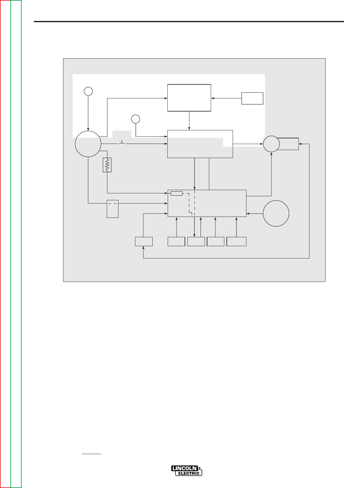
E-4
THEORY OF OPERATION
E-4
VARIABLE VOLTAGE
BOARD, METER SHUNT,
WIRE SPEED AND
REMOTE OUTPUT
CONTROLS
The optional variable voltage board
enables the LN-8 to be used with a con-
stant current power source. The vari-
able voltage board monitors the arc
voltage via leads #21 and #567 and
modifies the wire feed speed according
to arc voltage variations and require-
ments.
The wire speed control dictates to the
control board the directives of the
operator. The control board adjusts the
armature voltage applied to the wire
feed motor to change the motor speed.
The remote output control permits
power source control from the LN-8
unit. The remote control is coupled to
the welding power source via leads #75,
#76, and #77 through the input
receptacle.
The electrode meter shunt, which is
connected to and also in series with the
gun connector block, senses the weld-
ing current and arc voltage. This infor-
mation is used by the variable voltage
board and also the optional meter kit.
FIGURE E.3 – VARIABLE VOLTAGE BOARD, METER SHUNT, WIRE SPEED,
AND REMOTE OUTPUT CONTROLS
LN-8
REMOTE
OUTPUT
CONTROL
ELECTRODE
METER
SHUNT
WIRE
FEED
MOTOR
CIRCUIT
BREAKER
INPUT
RECEPTACLE
VARIABLE VOLTAGE
BOARD
CONTROL
BOARD
WIRE FEED
SPEED CONTROL
THERMAL
CIRCUIT
BREAKER
RELAY
BOARD
GLP REED
SWITCH TRIGGER
TRANS.
WIRE
FEED
SWITCH
INTERLOCK
SWITCH
FUSE
GUN
CABLE
RECEPTACLE
FIELD
ARMATURE
#3
2
A
OPTIONAL
BURNBACK
BOARD
CONTROL
#2
&
#4
C
O
N
T
A
C
T
O
R
#531
#31
2 OHMS
#32 #32A
#75
#76
#77
#21 #567
NOTE: Unshaded areas of block logic diagrams are the subject of discussion.
Return to Section TOC Return to Section TOC Return to Section TOC Return to Section TOC
Return to Master TOC Return to Master TOC Return to Master TOC Return to Master TOC
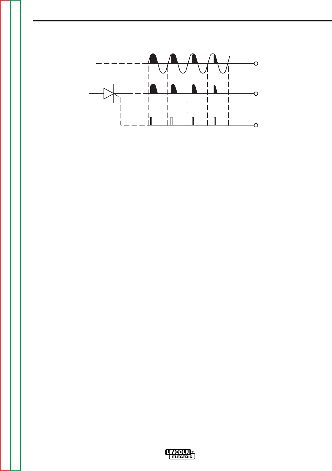
Return to Section TOC Return to Section TOC Return to Section TOC Return to Section TOC
Return to Master TOC Return to Master TOC Return to Master TOC Return to Master TOC
E-5
THEORY OF OPERATION
E-5
SCR OPERATION
A silicon controlled rectifier (SCR) is a
three terminal semi-conductor device
used to control currents to a load. Refer
to Figure E.4. An SCR acts very much
like a switch. When a gate signal is
applied to the SCR it is turned ON and
there is current flow from anode to cath-
ode. In the ON state the SCR acts like a
closed switch. When the SCR is turned
OFF there is no current flow, thus the
device acts like an open switch. As the
name suggests, the SCR is a rectifier,
so it passes current only during positive
half cycles of the AC supply, The posi-
tive half cycle is the portion of the sine
wave in which the anode of the SCR is
more positive than the cathode.
When an AC supply voltage is applied
to the SCR, the device spends a certain
portion of the AC cycle time in the ON
state and the remainder of the time in
the OFF state. The amount of time
spent in the ON state is controlled by
the gate.
An SCR is fired by a short burst of cur-
rent into the gate. This gate pulse must
be more positive than the cathode volt-
age. Since there is a standard PN junc-
tion between the gate and cathode, the
voltage between these terminals must
be slightly greater than 0.6 VDC. Once
the SCR has fired, it is not necessary to
continue the flow of gate current. As
long as current continues to flow from
anode to cathode the SCR will remain
on. When the anode to cathode current
drops below a minimum value, called
holding current, the SCR will shut off.
This normally occurs as the AC supply
voltage passes through zero into the
negative portion of the sine wave. If the
SCR is turned on early in the positive
half cycle, the conduction time is longer,
resulting in greater SCR output. If the
gate firing time is later in the cycle the
conduction time is less, resulting in
lower SCR output.
FIGURE E.4 – SILICON-CONTROLLED RECTIFIER OPERATION
LN-8
INPUT
CATHODE
GATE
GATE
OUTPUT
ANODE
NOTE: AS THE GATE PULSE IS
APPLIED LATER IN THE
CYCLE, THE SCR OUTPUT
IS DECREASED.


Return to Master TOC Return to Master TOC Return to Master TOC Return to Master TOC
LN-8
SECTION F
TROUBLESHOOTING AND REPAIR
SECTION F
TABLE OF CONTENTS
-TROUBLESHOOTING AND REPAIR SECTION-
Troubleshooting and Repair. . . . . . . . . . . . . . . . . . . . . . . . . . . . . . . . . . . . . . . . . . . . . . . . . Section F
How to Use Troubleshooting Guide. . . . . . . . . . . . . . . . . . . . . . . . . . . . . . . . . . . . . . . . . . . . . F-2
PC Board Troubleshooting Procedures . . . . . . . . . . . . . . . . . . . . . . . . . . . . . . . . . . . . . . . F-3
Troubleshooting Guide. . . . . . . . . . . . . . . . . . . . . . . . . . . . . . . . . . . . . . . . . . . . . . . . . . . . F-4
LN-8 Electrical Sequence of Operation . . . . . . . . . . . . . . . . . . . . . . . . . . . . . . . . . . . . . . . F-10
Test Procedures. . . . . . . . . . . . . . . . . . . . . . . . . . . . . . . . . . . . . . . . . . . . . . . . . . . . . . . . . F-12
Trigger Transformer Test . . . . . . . . . . . . . . . . . . . . . . . . . . . . . . . . . . . . . . . . . . . . . . . F-12
Internal Voltage Test . . . . . . . . . . . . . . . . . . . . . . . . . . . . . . . . . . . . . . . . . . . . . . . . . . F-14
1CR Relay Test . . . . . . . . . . . . . . . . . . . . . . . . . . . . . . . . . . . . . . . . . . . . . . . . . . . . . . F-17
Drive Motor Test . . . . . . . . . . . . . . . . . . . . . . . . . . . . . . . . . . . . . . . . . . . . . . . . . . . . . . F-20
Component Replacement Procedures . . . . . . . . . . . . . . . . . . . . . . . . . . . . . . . . . . . . . . . . F-24
Potentiometer Replacement. . . . . . . . . . . . . . . . . . . . . . . . . . . . . . . . . . . . . . . . . . . . . F-24
Circuit Breaker Replacement . . . . . . . . . . . . . . . . . . . . . . . . . . . . . . . . . . . . . . . . . . . . F-26
Ground Lead Protector Push Button Switch Replacement. . . . . . . . . . . . . . . . . . . . . . F-28
Trigger Transformer Replacement . . . . . . . . . . . . . . . . . . . . . . . . . . . . . . . . . . . . . . . . F-30
PC Board Replacement . . . . . . . . . . . . . . . . . . . . . . . . . . . . . . . . . . . . . . . . . . . . . . . . F-32
Wire Drive Assembly and Component Replacement . . . . . . . . . . . . . . . . . . . . . . . . . . F-35
Retest After Repair. . . . . . . . . . . . . . . . . . . . . . . . . . . . . . . . . . . . . . . . . . . . . . . . . . . . . . . F-40

Return to Section TOC Return to Section TOC Return to Section TOC Return to Section TOC
Return to Master TOC Return to Master TOC Return to Master TOC Return to Master TOC
LN-8
F-2
TROUBLESHOOTING AND REPAIR
F-2
This Troubleshooting Guide is provided to
help you locate and repair possible machine
malfunctions. Simply follow the three-step
procedure listed below.
Step 1. LOCATE PROBLEM (SYMPTOM).
Look under the column labeled “PROBLEM
(SYMPTOMS)”. This column describes
possible symptoms that the machine may
exhibit. Find the listing that best describes
the symptom that the machine is exhibiting.
Symptoms are grouped into the following
categories: function problems, feeding prob-
lems, and welding problems.
Step 2. PERFORM EXTERNAL TESTS.
The second column labeled “POSSIBLE
AREAS OF MISADJUSTMENT(S)” lists the
obvious external possibilities that may con-
tribute to the machine symptom. Perform
these tests/checks in the order listed. In
general, these tests can be conducted with-
out removing the case wrap-around cover.
Step 3. RECOMMENDED COURSE OF
ACTION
The last column labeled “Recommended
Course of Action” lists the most likely com-
ponents that may have failed in your
machine. It also specifies the appropriate
test procedure to verify that the subject
component is either good or bad. If there
are a number of possible components,
check the components in the order listed to
eliminate one possibility at a time until you
locate the cause of your problem.
All of the referenced test procedures
referred to in the Troubleshooting Guide are
described in detail at the end of this chap-
ter. Refer to the Troubleshooting and Repair
Table of Contents to locate each specific
Test Procedure. All of the specified test
points, components, terminal strips, etc. can
be found on the referenced electrical wiring
diagrams and schematics. Refer to the
Electrical Diagrams Section Table of
Contents to locate the appropriate diagram.
HOW TO USE TROUBLESHOOTING GUIDE
Service and Repair should only be performed by Lincoln Electric Factory Trained Personnel.
Unauthorized repairs performed on this equipment may result in danger to the technician and
machine operator and will invalidate your factory warranty. For your safety and to avoid
Electrical Shock, please observe all safety notes and precautions detailed throughout this
manual.
__________________________________________________________________________
WARNING
CAUTION
If for any reason you do not understand the test procedures or are unable to perform the
tests/repairs safely, contact the Lincoln Electric Service Department for technical trou-
bleshooting assistance before you proceed call 1-800-833-9353.
_____________________________________________________________
LN-8
Return to Section TOC Return to Section TOC Return to Section TOC Return to Section TOC
Return to Master TOC Return to Master TOC Return to Master TOC Return to Master TOC
TROUBLESHOOTING & REPAIR
F-3 F-3
Sometimes machine failures appear to be due to PC
board failures. These problems can sometimes be
traced to poor electrical connections. To avoid prob-
lems when troubleshooting and replacing PC boards,
please use the following procedure:
1. Determine to the best of your technical ability
that the PC board is the most likely component
causing the failure symptom.
2. Check for loose connections at the PC board to
assure that the PC board is properly connected.
3. If the problem persists, replace the suspect PC
board using standard practices to avoid static
electrical damage and electrical shock. Read
the warning inside the static resistant bag and
perform the following procedures:
PC board can be damaged by static electricity.
- Remove your body’s static
charge before opening the static-
shielding bag. Wear an anti-static
wrist strap. For safety, use a 1
Meg ohm resistive cord connected
to a grounded part of the
equipment frame.
- If you don’t have a wrist strap,
touch an un-painted, grounded,
part of the equipment frame. Keep
touching the frame to prevent
static build-up. Be sure not to
touch any electrically live parts at
the same time.
- Tools which come in contact with the PC board must
be either conductive, anti-static or static-dissipative.
ELECTRIC SHOCK
can kill.
•Have an electrician install and
service this equipment. Turn the
input power OFF at the fuse box
before working on equipment. Do
not touch electrically hot parts.
- Remove the PC board from the static-shielding bag
and place it directly into the equipment. Don’t set the
PC board on or near paper, plastic or cloth which
could have a static charge. If the PC board can’t be
installed immediately, put it back in the static-shield-
ing bag.
- If the PC board uses protective shorting jumpers,
don’t remove them until installation is complete.
- If you return a PC board to The Lincoln Electric
Company for credit, it must be in the static-shielding
bag. This will prevent further damage and allow
proper failure analysis.
4. Test the machine to determine if the failure
symptom has been corrected by the
replacement PC board.
NOTE:It is desirable to have a spare (known good)
PC board available for PC board troubleshooting.
NOTE:Allow the machine to heat up so that all
electrical components can reach their operating
temperature.
5. Remove the replacement PC board and
substitute it with the original PC board to
recreate the original problem.
a. If the original problem does not reappear by
substituting the original board, then the PC
board was not the problem. Continue to look
for bad connections in the control wiring
harness, junction blocks, and terminal strips.
b. If the original problem is recreated by the
substitution of the original board, then the PC
board was the problem. Reinstall the
replacement PC board and test the machine.
6. Always indicate that this procedure was
followed when warranty reports are to be
submitted.
NOTE:Following this procedure and writing on the
warranty report, “INSTALLED AND SWITCHED PC
BOARDS TO VERIFY PROBLEM,” will help avoid
denial of legitimate PC board warranty claims.
PC BOARD TROUBLESHOOTING PROCEDURES
ATTENTION
Static-Sensitive
Devices
Handle only at
Static-Safe
Workstations
WARNING
CAUTION

Return to Section TOC Return to Section TOC Return to Section TOC Return to Section TOC
Return to Master TOC Return to Master TOC Return to Master TOC Return to Master TOC
1. Check the Ground Lead
Protector (GLP). Reset if
necessary.
2. Check the circuit breaker. Reset
if necessary.
3. Make sure 115VAC is being
applied to the LN-8 at the input
receptacle. Pin “C” lead #31 and
pin “D” lead #32.
4. Check the 1/2 amp fuse located
on the relay board. Replace if
necessary.
5. If the LN-8 has a variable voltage
board and the power source is a
constant current supply, check to
make sure the switch on the vari-
able voltage board is in the “VV”
position.
6. If the switch on the variable
board is in the “VV” position,
make sure the power source is
set for an open circuit voltage of
30VDC or more.
F-4
TROUBLESHOOTING AND REPAIR
F-4
LN-8
Observe all Safety Guidelines detailed throughout this manual
If for any reason you do not understand the test procedures or are unable to perform the tests/repairs safely, contact the Lincoln Electric
Service Department for technical troubleshooting assistance before you proceed. Call 1-800-833-9353.
CAUTION
POSSIBLE AREAS OF
MISADJUSTMENT(S) RECOMMENDED
COURSE OF ACTION
No wire feed or arc voltage when
the gun trigger is activated. The
drive rolls do not turn. The LN-8
appears “dead”.
1. Check for loose or faulty con-
nections between the input
receptacle, the circuit breaker,
and the 2 ohm resistor. See
wiring diagram.
2. Check the 2 ohm resistor.
Replace if faulty.
3. Perform the Trigger
Transformer Test.
4. Perform the Internal Voltage
Test.
5. Perform the 1CR Relay Test.
6. Check the relay board. Replace
if faulty.
7. Check the variable voltage board
(if used). Replace if faulty.
TROUBLESHOOTING GUIDE
PROBLEMS
(SYMPTOMS)
FUNCTION PROBLEMS

Return to Section TOC Return to Section TOC Return to Section TOC Return to Section TOC
Return to Master TOC Return to Master TOC Return to Master TOC Return to Master TOC
1. The 1CR relay, located on the
power board, may be faulty.
Check or replace. Note: The
relay may operate but the indi-
vidual contacts may not be func-
tioning properly.
2. If a burnback kit is installed,
remove and install the jumper
plug. If the problem is solved,
the burnback kit is faulty.
3. Check the #2 and #4 leads in the
LN-8 wiring harness for loose or
faulty connections. See wiring
diagram.
1. The 1CR relay may be stuck
closed. Perform the 1CR Relay
Test.
2. Check the relay board. Replace
if faulty.
1. The 2CR reed switch may be
faulty. Check to see if it closes
when welding.
2. Check the interlock switch (S2)
for proper operation.
3. Check the continuity (zero ohms)
of leads #523 and #536 between
the interlock switch (S2) and the
relay board. See wiring diagram.
4. The relay board may be faulty.
1. Check the welding cables for
loose or faulty connections.
2. Put a jumper wire from #2 to #4
on the power source terminal
strip. (machines with 14 pin
amphenols pin C to pin D). If the
arc voltage is not present at the
output terminals, the power
source is faulty. If the arc volt-
age IS present, the problem is in
the wire feeder or control cable.
3. Check the continuity of leads #2
and #4 through the control cable.
Replace if “open”.
4. The welding gun may be faulty.
Check or replace.
1. Disconnect the gun trigger cable.
If the problem is solved, the gun
trigger or cable is faulty. Repair
or replace.
1. Check leads #529 and #528 for
loose or faulty connections
between the 2CR reed switch
and the control board and motor
thermal circuit breaker. See
wiring diagram.
The wire feeds when the gun trig-
ger is activated but there is no arc
voltage.
The wire continues to feed with the
gun trigger open, and the wire is
electrically “hot”. The interlock
switch is in the “off” position.
With the interlock switch (S2) in the
“ON” postion, the wire feed stops
when the gun trigger is released.
POSSIBLE AREAS OF
MISADJUSTMENT(S) RECOMMENDED
COURSE OF ACTION
PROBLEMS
(SYMPTOMS)
F-5
TROUBLESHOOTING AND REPAIR
F-5
LN-8
Observe all Safety Guidelines detailed throughout this manual
If for any reason you do not understand the test procedures or are unable to perform the tests/repairs safely, contact the Lincoln Electric
Service Department for technical troubleshooting assistance before you proceed. Call 1-800-833-9353.
CAUTION
FUNCTION PROBLEMS (Continued)

Return to Section TOC Return to Section TOC Return to Section TOC Return to Section TOC
Return to Master TOC Return to Master TOC Return to Master TOC Return to Master TOC
F-6
TROUBLESHOOTING AND REPAIR
F-6
LN-8
If for any reason you do not understand the test procedures or are unable to perform the tests/repairs safely, contact the Lincoln Electric
Service Department for technical troubleshooting assistance before you proceed. Call 1-800-833-9353.
CAUTION
The circuit breaker (5 amp)
repeatedly trips when the gun trig-
ger is activated.
The circuit breaker (5 amp) trips
when power is applied to the LN-8.
Gun trigger is NOT activated.
The 1/2 amp fuse on the relay
board repeatedly fails.
The drive motor thermostat “opens”
while welding.
1. Check or replace the gun trigger
and leads. Make sure the trigger
leads are not shorted to the elec-
trode or work cables.
2. Disconnect any accessory that
may be connected to terminals
#7 and #32A. See wiring dia-
gram. If the problem is resolved,
the accessory may be faulty.
1. Disconnect any kits or acces-
sories that may be incorporated
in the LN-8. Be sure to install
any necessary jumper plugs. If
problem is resolved the fault may
be in the disconnected kit.
1. Check to make sure the correct
input voltage (115VAC) is being
applied to the LN-8.
2. Very rapid and repetitive gun
triggering can possibly cause the
field fuse to fail.
1. Check for mechanical restric-
tions in the wire feeding path.
This condition could cause the
motor to overheat.
2. The electrode may be rusty or
dirty. Clean or replace.
1. Perform the Trigger
Transformer Test.
2. Perform the Drive Motor Test.
3. Remove the molex plug from the
relay board. If the circuit breaker
continues to trip, the control
board may be faulty. If the cir-
cuit breaker does not trip, the
relay board may be faulty.
1. Check the wiring harness leads
#32, #32A, #31, and #531 for
shorts or grounds. See wiring
diagram.
2. Perform the Trigger
Transformer Test.
3. Remove the molex plug from the
relay board. If the circuit breaker
continues to trip, the control
board may be faulty. If the cir-
cuit breaker does not trip, the
relay board may be faulty.
4. Perform the Drive Motor Test.
1. Perform the Drive Motor Test.
2. Perform the Trigger
Transformer Test.
2. The relay board may be faulty.
1. Perform the Drive Motor Test.
POSSIBLE AREAS OF
MISADJUSTMENT(S) RECOMMENDED
COURSE OF ACTION
PROBLEMS
(SYMPTOMS)
Observe all Safety Guidelines detailed throughout this manual
FUNCTION PROBLEMS (Continued)

Return to Section TOC Return to Section TOC Return to Section TOC Return to Section TOC
Return to Master TOC Return to Master TOC Return to Master TOC Return to Master TOC
F-7
TROUBLESHOOTING AND REPAIR
F-7
LN-8
If for any reason you do not understand the test procedures or are unable to perform the tests/repairs safely, contact the Lincoln Electric
Service Department for technical troubleshooting assistance before you proceed. Call 1-800-833-9353.
CAUTION
The wire feed speed cannot be
controlled. The motor runs and
feeds wire but the speed cannot
be changed regardless of control
setting.
The wire feed “coasts” when the
gun trigger is released.
The wire feeds normally and welds
but the solenoid is not operating.
When the gun trigger is activated
the wire “backs up” instead of feed-
ing forward.
1. If the LN-8 is being used for sub-
merged arc welding with the vari-
able voltage board switch in the
VV position, change it to the CV
position. If proper motor speed
control returns, the variable volt-
age board may be faulty.
1. Make sure the gun trigger is not
“sticking”.
1. Check or replace the solenoid.
1. Check wire feed direction switch
for proper direction and operation.
1. Check for loose connections
between the speed control, the
control board, and the variable
voltage board. See wiring
diagram.
2. Check the speed control rheostat
for proper operation. Normal
resistance is 5000 ohms.
3. Perform the Drive Motor Test.
4. The control board may be faulty.
1. Perform the 1CR Relay Test.
1. With the gun trigger activated,
check for the presence of
115VAC at terminals 32A and 7.
If the proper voltage is present,
the solenoid may be faulty. If the
correct voltage (115VAC) is NOT
present, the relay board may be
faulty.
1. The 1CR relay may be faulty.
Check or replace.
POSSIBLE AREAS OF
MISADJUSTMENT(S) RECOMMENDED
COURSE OF ACTION
PROBLEMS
(SYMPTOMS)
Observe all Safety Guidelines detailed throughout this manual
FUNCTION PROBLEMS (Continued)

Return to Section TOC Return to Section TOC Return to Section TOC Return to Section TOC
Return to Master TOC Return to Master TOC Return to Master TOC Return to Master TOC
F-8
TROUBLESHOOTING AND REPAIR
F-8
LN-8
If for any reason you do not understand the test procedures or are unable to perform the tests/repairs safely, contact the Lincoln Electric
Service Department for technical troubleshooting assistance before you proceed. Call 1-800-833-9353.
CAUTION
When the gun trigger is activated,
the drive rolls turn but the wire will
not feed or wire feeding is rough.
1. Check or replace the gun cable.
It may be kinked, clogged or
twisted.
2. Make certain the drive rolls and
guide tubes are correct for the
wire being used.
3. Check or replace the gun contact
tip.
4. The electrode wire may be rusty
or dirty. Replace if necessary.
1. If conditions are extremely dirty,
install a wiper on the wire before
it enters the guide tube. Use a
piece of cloth saturated with
“Pyroil B”.
POSSIBLE AREAS OF
MISADJUSTMENT(S) RECOMMENDED
COURSE OF ACTION
PROBLEMS
(SYMPTOMS)
Observe all Safety Guidelines detailed throughout this manual
FEEDING PROBLEMS

Return to Section TOC Return to Section TOC Return to Section TOC Return to Section TOC
Return to Master TOC Return to Master TOC Return to Master TOC Return to Master TOC
F-9
TROUBLESHOOTING AND REPAIR
F-9
LN-8
If for any reason you do not understand the test procedures or are unable to perform the tests/repairs safely, contact the Lincoln Electric
Service Department for technical troubleshooting assistance before you proceed. Call 1-800-833-9353.
CAUTION
The welding arc is variable or
“hunting”.
Poor arc striking with sticking or
“blast offs”. The weld bead may
also be ropey and display weld
porosity.
1. Make sure the welding parame-
ters are correct for the welding
procedure being used.
2. Check the welding cables for
loose or faulty connections.
3. The gun cable may be faulty.
Check or replace.
4. The gun contact tip may be
worn. Check or replace.
5. The welding power supply may
be faulty. Check or replace.
1. Make sure the welding parame-
ters and techniques are correct
for the welding procedure being
used.
2. Check the welding cables for
loose or faulty connections.
3. The gun cable may be faulty.
Check or replace.
4. The gun contact tip may be
worn. Check or replace.
5. The welding power source may
be faulty. Check or replace.
1. Put the power source in
“Machine Control” and check if
the welding performance
improves. If the problem is
resolved, check or replace the
control cable and/or check the
output control in the LN-8.
2. Perform the Drive Motor Test.
1. Put the power source in
“Machine Control” and check if
welding performance improves.
If the problem is resolved, check
or replace the control cable
and/or check the output control
in the LN-8.
POSSIBLE AREAS OF
MISADJUSTMENT(S) RECOMMENDED
COURSE OF ACTION
PROBLEMS
(SYMPTOMS)
Observe all Safety Guidelines detailed throughout this manual
WELDING PROBLEMS

Return to Section TOC Return to Section TOC Return to Section TOC Return to Section TOC
Return to Master TOC Return to Master TOC Return to Master TOC Return to Master TOC
F-10
TROUBLESHOOTING AND REPAIR
F-10
LN-8 ELECTRICAL SEQUENCE OF OPERATION
FIGURE F.1 – LN-8 ELECTRICAL SEQUENCE OF OPERATION
LN-8
TURN ON POWER SOURCE
PRESS GUN TRIGGER
CLOSES 524-528
ENERGIZES 1 CR
CLOSES 531-7
OPENS 682-683
CLOSES 683-32A CIRCUIT
REVERSES WIRE
FEED MOTOR
FIELD
ENERGIZES
CONTROL CIRCUIT
(AND AUX. EQUIPMENT IF
CONNECTED TO 7-32A)
WIRE FEEDS DOWN
ARC STARTS
MOTOR ACCELERATES
TO WELDING SPEED
WELDING
INTERLOCKS 1 CR IF
INTERLOCK SWITCH
IS CLOSED
ENERGIZES 2 CR
(REED SWITCH)
CLOSES 2-4 CIRCUIT
ENERGIZES POWER
SOURCE PILOT RELAY
ENERGIZES
POWER SOURCE
CONTACTOR
ELECTRODE NOW
"HOT" TO GROUND

Return to Section TOC Return to Section TOC Return to Section TOC Return to Section TOC
Return to Master TOC Return to Master TOC Return to Master TOC Return to Master TOC
F-11
TROUBLESHOOTING AND REPAIR
F-11
FIGURE F.1 – LN-8 ELECTRICAL SEQUENCE OF OPERATION (continued)
LN-8
DE-ENERGIZES
2 CR
REED SWITCH
OPENS INTERLOCK
ON 1 CR (NOTE 2)
OPENS 531-7
DE-ENERGIZES 1 CR
OPENS 683-32A CIRCUIT
CLOSES 682-683
REVERSES
MOTOR FIELD
WELDING
ELECTRODE IS
COLD TO WORK
RELEASE
GUN TRIGGER
OPENS 2-8 (NOTE 1)
OPENS 2-4 CIRCUIT
DE-ENERGIZES
POWER SOURCE
CONTACTOR
BREAK
WELDING ARC
DE-ENERGIZES
POWER SOURCE
PILOT RELAY DISCONNECTS MOTOR ARMATURE
AND CONTROL CIRCUIT FROM
INPUT AC LINE - (DE-ENERGIZES
AUX. EQUIPMENT IF CONNECTED) 3CR (NOTE 3)
REED SWITCH
MOMENTARILY
CLOSES
DYNAMIC BRAKE
CURRENT FLOWS
THROUGH FREE
WHEELING DIODE (D-7 ON
CONTROL BOARD)
DISCHARGES SLOW
ACCELERATION
CAPACITOR (C3 ON
CONTROL BOARD)
MOTOR STOPS
RESETS SLOW
ACCELERATION
CIRCUIT
UNIT READY
FOR NEXT WELD
NOTE 1: When interlock is open.
NOTE 2: When interlock is closed.
NOTE 3: 3 CR is not used on units with code no. 7926 and up.

Return to Section TOC Return to Section TOC Return to Section TOC Return to Section TOC
Return to Master TOC Return to Master TOC Return to Master TOC Return to Master TOC
LN-8
F-12
TROUBLESHOOTING AND REPAIR
F-12
TEST DESCRIPTION
This test will aid the technician in determining if the Trigger Transformer is functioning
properly.
MATERIALS NEEDED
115 VAC power supply
5/16 in. nutdriver
Volt-Ohmmeter (Multimeter)
Service and repair should be performed only by Lincoln Electric factory trained per-
sonnel. Unauthorized repairs performed on this equipment could result in danger to
the technician or the machine operator and will invalidate your factory warranty. For
your safety and to avoid electrical shock, please observe all safety notes and precau-
tions detailed throughout this manual.
If for any reason you do not understand the test procedures or are unable to perform
the tests/repairs safely, contact the Lincoln Electric service department for technical
troubleshooting assistance before you proceed.
Call (800) 833-9353 (WELD).
_____________________________________________________________
WARNING
TRIGGER TRANSFORMER TEST
This procedure takes approximately 8 minutes to perform.
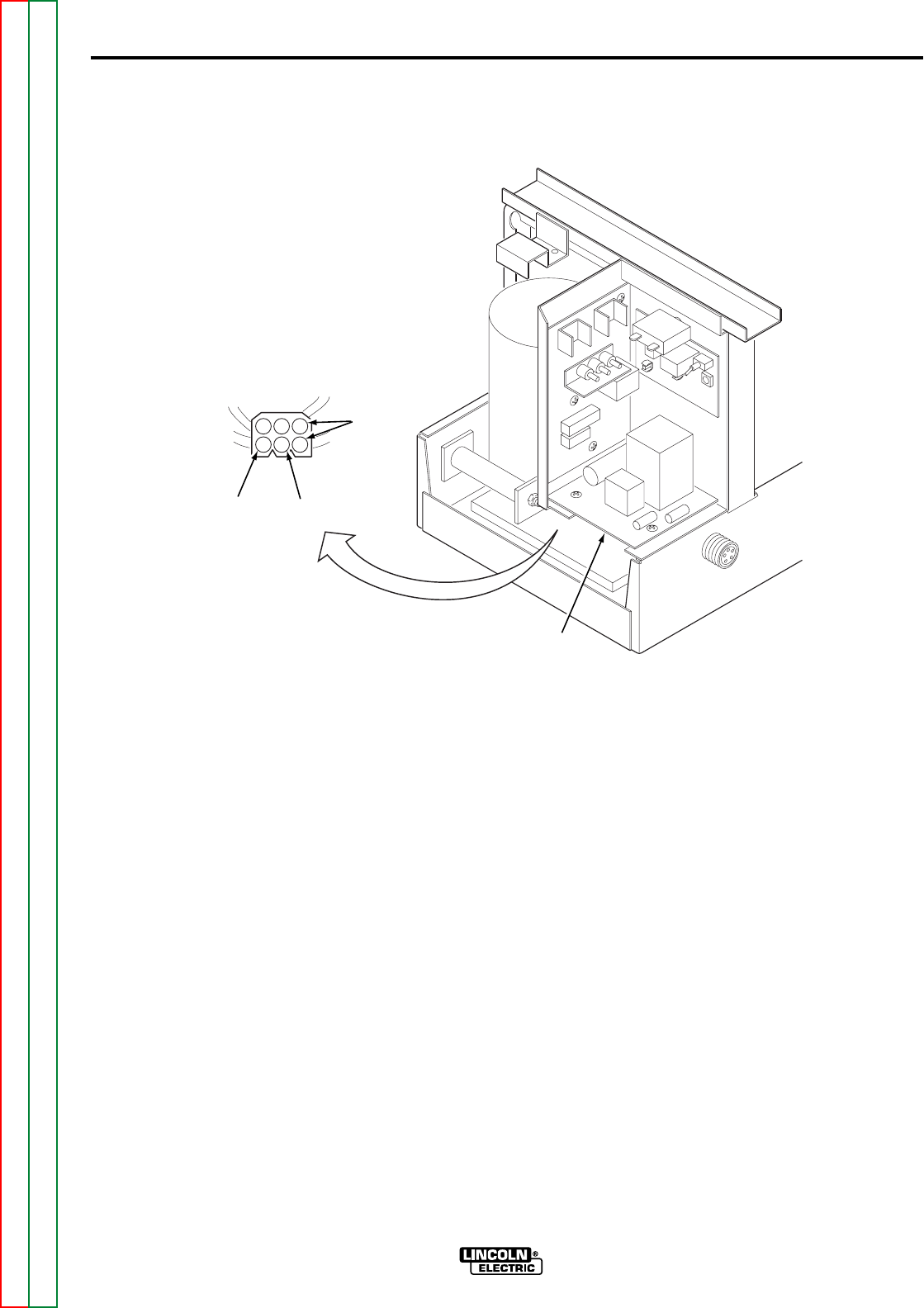
F-13
TROUBLESHOOTING AND REPAIR
F-13
TEST PROCEDURE
1. Remove input power to the LN-8.
2. Using the 5/16 in. nutdriver,
remove the screws holding the left
side cover assembly.
3. Disconnect the Molex plug from
the under-side of the relay board.
See Figure F.2.
4. Apply power (115VAC) to the
black primary transformer leads,
pins 2 and 3.
5. Using the voltmeter, check for
approximately 24VAC at the red
secondary leads, pins 1 and 4.
6. If 115VAC is applied to the black
primary leads (2 and 3) and the
secondary voltage (red leads 1
and 4) is missing or low, the trig-
ger transformer may be faulty.
Replace.
7. Reconnect the Molex plug to the
underside of the relay board.
8. Install the screws that secure the
left side cover assembly.
TRIGGER TRANSFORMER TEST (continued)
FIGURE F.2 – TRIGGER TRANSFORMER TEST POINTS
LN-8
Return to Section TOC Return to Section TOC Return to Section TOC Return to Section TOC
Return to Master TOC Return to Master TOC Return to Master TOC Return to Master TOC
654
321
BLACK BLACK
RED
RELAY
BOARD

Return to Section TOC Return to Section TOC Return to Section TOC Return to Section TOC
Return to Master TOC Return to Master TOC Return to Master TOC Return to Master TOC
F-14
TROUBLESHOOTING AND REPAIR
F-14
LN-8
TEST DESCRIPTION
This test will aid the technician in determining if the correct voltages are present in the LN-8.
MATERIALS NEEDED
5/16 in. nutdriver
Volt-Ohmmeter
Wiring diagram
INTERNAL VOLTAGE TEST
Service and repair should be performed only by Lincoln Electric factory trained per-
sonnel. Unauthorized repairs performed on this equipment could result in danger to
the technician or the machine operator and will invalidate your factory warranty. For
your safety and to avoid electrical shock, please observe all safety notes and precau-
tions detailed throughout this manual.
If for any reason you do not understand the test procedures or are unable to perform
the tests/repairs safely, contact the Lincoln Electric service department for technical
troubleshooting assistance before you proceed.
Call (800) 833-9353 (WELD).
_____________________________________________________________
WARNING
This procedure takes approximately 20 minutes to perform.
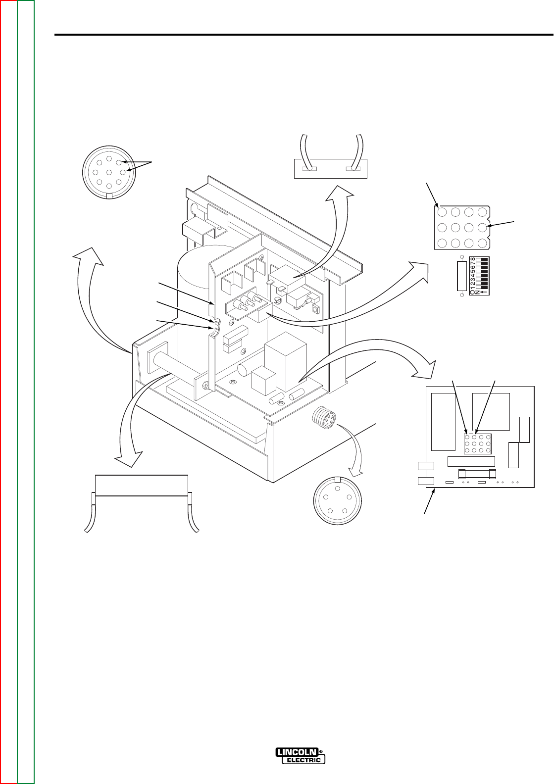
Return to Section TOC Return to Section TOC Return to Section TOC Return to Section TOC
Return to Master TOC Return to Master TOC Return to Master TOC Return to Master TOC
F-15
TROUBLESHOOTING AND REPAIR
F-15
TEST DESCRIPTION
1. Remove input power to the LN-8.
2. Using the 5/16 in. nutdriver,
remove the screws from the left
side cover assembly.
3. Lift the left side cover.
4. Apply 115VAC to the input
receptacle at pins C and D.
5. Using the voltmeter, carefully
test the voltages per Table F.1
at the test points shown in
Figure F.3.
6. When testing is complete,
install the screws that secure
the left side cover assembly.
LN-8
INTERNAL VOLTAGE TEST (continued)
FIGURE F.3 – VOLTAGE TEST POINTS
32 32A
INPUT
CIRCUIT
BREAKER CONTROL
BOARD
CONNECTOR
PLUG
PIN #12
(32A)
PIN #2
(7)
7 32A 525
(A)
RELAY
BOARD
627
626
PIN #1
(32A) PIN #4
(531)
GUN TRIGGER
RECEPTACLE
A
BC
D
E
2 OHM
RESISTOR (R4)
31 531
CONTROL
BOARD
541
539
A
HD
C
B
115 VAC
APPLIED
E
F
G
INPUT
RECEPTACLE

INTERNAL VOLTAGE TEST (continued)
TABLE F.1 – VOLTAGE TEST POINTS
Return to Section TOC Return to Section TOC Return to Section TOC Return to Section TOC
Return to Master TOC Return to Master TOC Return to Master TOC Return to Master TOC
F-16
TROUBLESHOOTING AND REPAIR
F-16
LN-8
ACCEPTABLE
CHECKPOINT TEST VOLTAGE
LOCATIONS DESCRIPTION LEAD NO. READING
Input Circuit Breaker Input voltage before the #31 and #32 103 to 126VAC
and circuit breaker and 2
Resistor R4 ohm resistor (R4).
Input Circuit Breaker Input voltage after the #31 and #32A 103 to 126VAC
and circuit breaker.
Resistor R4
Input Circuit Breaker Input voltage after the #531 and #32A 103 to 126VAC
and circuit breaker and 2
Resistor R4 ohm resistor (R4).
Gun trigger receptacle Check voltage across #524 (pin A) and 34 to 42VDC
pins A and C gun trigger - #528 (pin C)
- trigger open.
Terminals #7 and #32A Auxiliary terminals #7 and #32A 103 to 126VAC
located on relay board (gas solenoid)
Note: Gun trigger must
be activated.
Terminals #626 and Drive motor field #626 and #627 102 to 125VDC
#627 located on relay voltage.
board
Terminals #539 and Drive motor armature #539 and #541 4VDC (min) -
#541 located on control voltage. 90VDC (max).
board Note: Gun trigger must
be activated and
armature voltage will
be dependent upon wire
speed setting.
Control board Check that 115VAC is #32A (pin 12) and 103 to 126VAC
connector plug being applied to control #7 (pin 2)
board when gun trigger
is activated.
Relay board connector Check that 115VAC is #32A (pin 1) and 103 to 126VAC
plug being applied to the #531 (pin 4)
control board.

Return to Section TOC Return to Section TOC Return to Section TOC Return to Section TOC
Return to Master TOC Return to Master TOC Return to Master TOC Return to Master TOC
F-17
TROUBLESHOOTING AND REPAIR
F-17
LN-8
TEST DESCRIPTION
This test will determine if the control relay is functioning properly by measuring the resistance
across the contacts when the relay is energized and de-energized.
MATERIALS NEEDED
Volt-Ohmmeter
24VDC power supply
5/16 in. nutdriver
1CR RELAY TEST
Service and repair should be performed only by Lincoln Electric factory trained per-
sonnel. Unauthorized repairs performed on this equipment could result in danger to
the technician or the machine operator and will invalidate your factory warranty. For
your safety and to avoid electrical shock, please observe all safety notes and precau-
tions detailed throughout this manual.
If for any reason you do not understand the test procedures or are unable to perform
the tests/repairs safely, contact the Lincoln Electric service department for technical
troubleshooting assistance before you proceed.
Call (800) 833-9353 (WELD).
_____________________________________________________________
WARNING
This procedure takes approximately 15 minutes to perform.
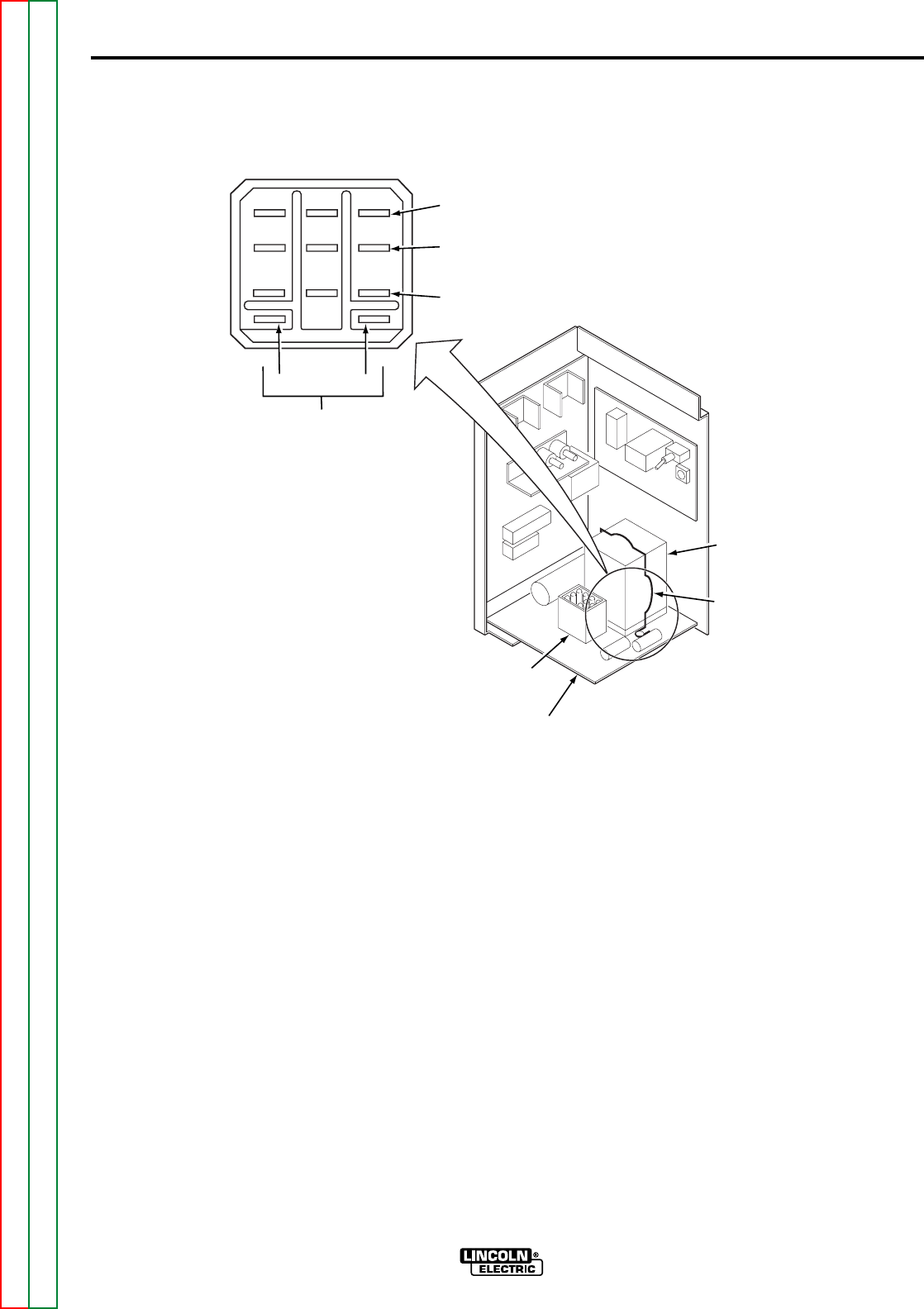
Return to Section TOC Return to Section TOC Return to Section TOC Return to Section TOC
Return to Master TOC Return to Master TOC Return to Master TOC Return to Master TOC
F-18
TROUBLESHOOTING AND REPAIR
F-18
TEST PROCEDURE
1. Remove input power to the LN-8.
2. Using the 5/16 in. nutdriver,
remove the screws from the left
side cover assembly.
3. Lift the left side cover.
4. Locate the 1CR relay. Slide the
retaining clip off the relay and
carefully remove the relay from the
relay board. See Figure F.4.
Note: The Molex plug located on the
relay board may have to be removed to
gain access to the 1CR relay.
5. Connect the 24VDC supply to ter-
minals A- and B+ on the 1CR
relay. Do not energize the power
supply at this time.
6. Connect the ohmmeter across the
first set of terminals shown in
Table F.2.
LN-8
1CR RELAY TEST (continued)
FIGURE F.4 – 1CR RELAY TEST POINTS
123
456
789
AB
NORMALLY CLOSED
NORMALLY OPEN
COMMON
-+
24VDC
MOLEX
PLUG
RELAY
BOARD
RETAINING
CLIP
1CR RELAY

Return to Section TOC Return to Section TOC Return to Section TOC Return to Section TOC
Return to Master TOC Return to Master TOC Return to Master TOC Return to Master TOC
F-19
TROUBLESHOOTING AND REPAIR
F-19
7. Measure the resistance across the
contacts. A resistance of less than
one ohm indicates that the con-
tacts are closed. An infinite resis-
tance indicates that the contacts
are open. Energize the 24VDC
power supply and measure the
resistance again. Compare to the
conditions given in Table F.2. If the
readings do not match the table,
the relay is faulty and should be
replaced.
8. Repeat the above procedure for all
of the contacts.
9. Re-install relay into the relay
board.
10. Install the screws that secure the
left side cover assembly.
1CR RELAY TEST (continued)
TABLE F.2 – RELAY TEST TERMINAL CONNECTIONS
LN-8
Terminals Terminals
A&B A&B
Terminals Energized De-energized
7-1 Open Closed
7-4 Closed Open
8-2 Open Closed
8-5 Closed Open
9-3 Open Closed
9-6 Closed Open

Return to Section TOC Return to Section TOC Return to Section TOC Return to Section TOC
Return to Master TOC Return to Master TOC Return to Master TOC Return to Master TOC
F-20
TROUBLESHOOTING AND REPAIR
F-20
LN-8
TEST DESCRIPTION
This test will help determine if the drive motor is functioning correctly.
MATERIALS NEEDED
5/16 in. nutdriver
Volt-Ohmmeter
Variable DC voltage supply 0 to 90VDC
Isolated DC voltage supply 120VDC
DRIVE MOTOR TEST
Service and repair should be performed only by Lincoln Electric factory trained per-
sonnel. Unauthorized repairs performed on this equipment could result in danger to
the technician or the machine operator and will invalidate your factory warranty. For
your safety and to avoid electrical shock, please observe all safety notes and precau-
tions detailed throughout this manual.
If for any reason you do not understand the test procedures or are unable to perform
the tests/repairs safely, contact the Lincoln Electric service department for technical
troubleshooting assistance before you proceed.
Call (800) 833-9353 (WELD).
_____________________________________________________________
WARNING
This procedure takes approximately 20 minutes to perform.
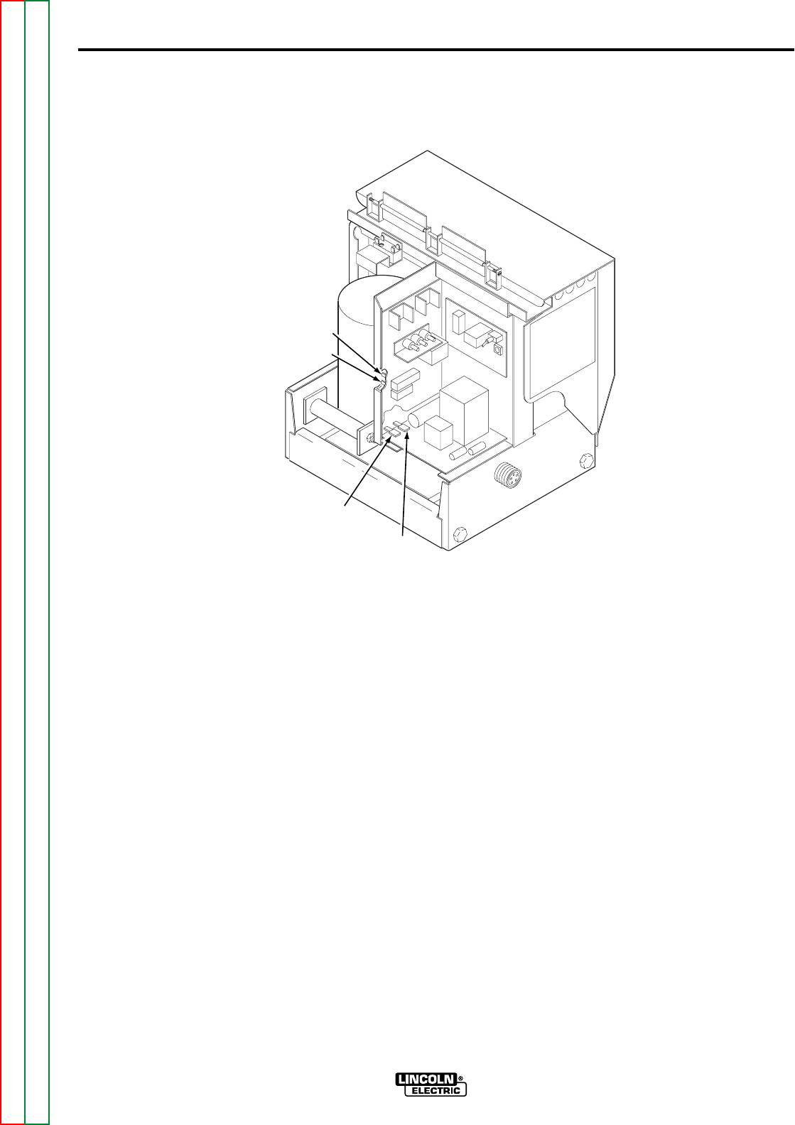
F-21
TROUBLESHOOTING AND REPAIR
F-21
TEST PROCEDURE
1. Remove input power to LN-8.
2. Remove the electrode wire or dis-
engage drive rolls.
3. Using the 5/16 in. nutdriver,
remove the screws from the left
side cover assembly.
4. Lift the left side cover.
5. Locate leads #539 and #541 at the
control board. See Figure F.5.
DRIVE MOTOR TEST (continued)
FIGURE F.5 – DRIVE MOTOR TEST POINTS
LN-8
Return to Section TOC Return to Section TOC Return to Section TOC Return to Section TOC
Return to Master TOC Return to Master TOC Return to Master TOC Return to Master TOC
#626
#627
#541
#539
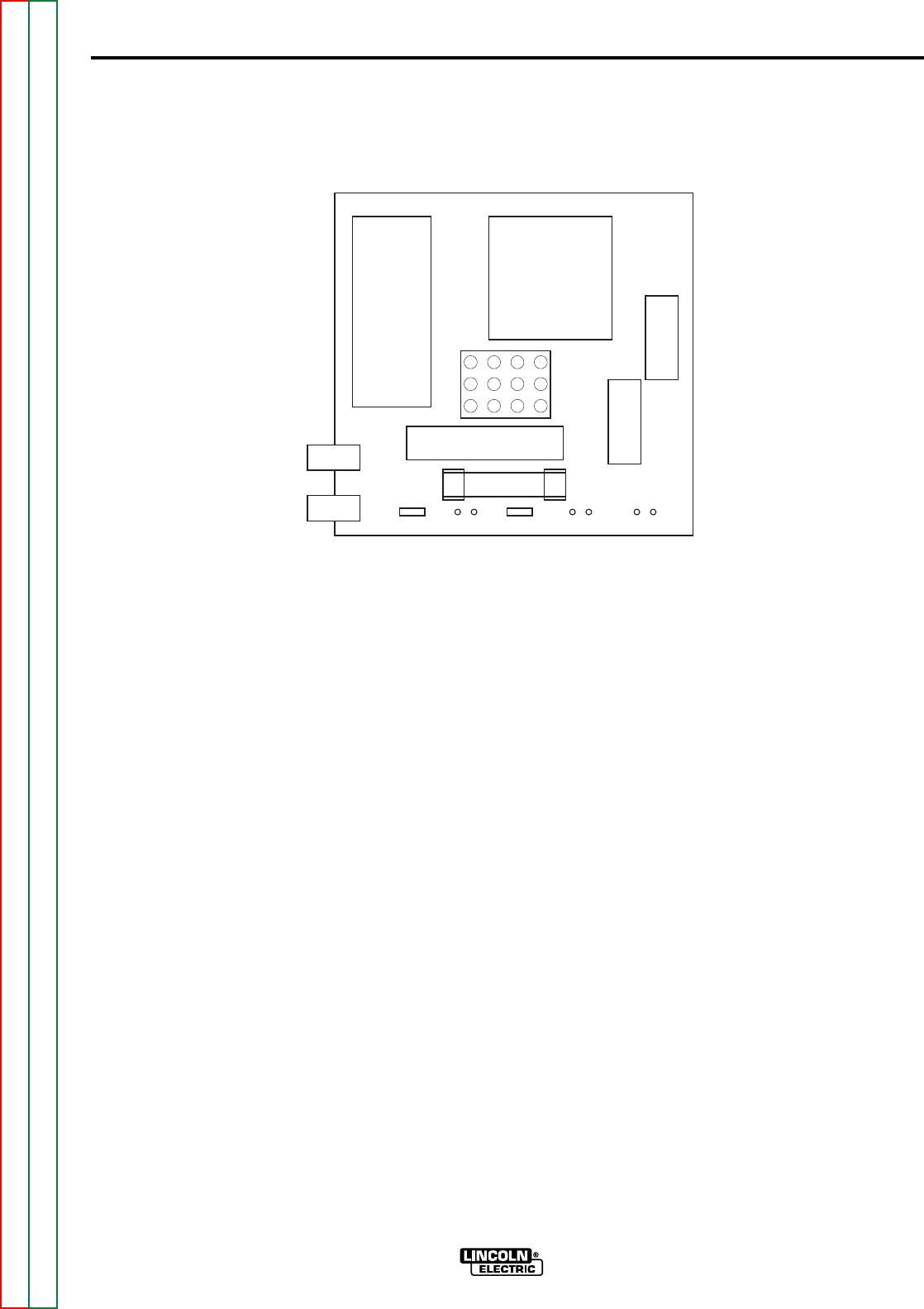
F-22
TROUBLESHOOTING AND REPAIR
F-22
6. Locate leads #626 and #627 at the
relay board.
7. If a variable voltage board is
installed in the LN-8, make cer-
tain the mode switch is in the CV
position.
8. Apply 115VAC to the input recep-
tacle at pins C and D.
9. With the gun trigger activated or
the gun trigger terminals jumpered
together, (see wiring diagram),
check the motor armature volts at
leads #541 (+) and #539 (-).
Normal is 5 to 95VDC dependent
upon the setting of the wire feed
speed control.
10. With the LN-8 at idle (gun trigger
NOT activated) check the motor
field voltage at lead #626 and
#627. Normal is 115VDC. When
the gun trigger is activated or the
gun terminals jumpered together,
Figure F.6, the field voltage polari-
ty should reverse from the idle
state. Normal is 115VDC and is
independent of motor speed.
Note: The wire feed direction switch
(S3) must be in the forward, or “weld-
ing” position.
11. If the above voltages are present
and motor does not operate, the
motor, motor brushes, or the gear
box may be faulty. If the armature
voltage is not correct (leads #539
and #541), the control board may
be faulty. If the field voltage is not
correct (leads #626 and #627), the
1CR relay or relay board may be
faulty.
DRIVE MOTOR TEST (continued)
FIGURE F.6 – GUN TERMINAL JUMPER LOCATIONS
LN-8
Return to Section TOC Return to Section TOC Return to Section TOC Return to Section TOC
Return to Master TOC Return to Master TOC Return to Master TOC Return to Master TOC
1CR
RELAY
627
626 7 529 32A 524(A) 525(A)
LN-8 RELAY

F-23
TROUBLESHOOTING AND REPAIR
F-23
To further check the drive motor:
12. Remove input power (115VAC)
from the LN-8.
13. Locate and remove leads #539
and #541 from the control board,
see Figure F.5.
14. Locate and remove leads #626
and #627 from the relay board.
15. Using the ohmmeter, measure the
resistances per Table F.3.
16. If the motor resistance test is
good, proceed to the Motor
Applied Voltage Test.
MOTOR APPLIED
VOLTAGE TEST
1. Carefully connect the isolated
120VDC supply (supply turned off)
to motor leads #626 and #627, see
Figure F.5.
2. Carefully connect the variable 0 to
120VDC supply (supply turned off)
to motor leads #539 and #541.
3. Apply field voltage first (leads #626
and #627) to the motor. Then
slowly apply the armature voltage
at leads #539 and #541.
4. The motor should run and the
speed should vary with changes to
the armature voltage.
5. If the motor does NOT run and
change speed correctly, the motor
or gear box may be faulty.
6. To stop the motor, remove the
armature voltage first, leads #539
and #541.
AFTER TESTING
1. Replace motor leads.
2. Install the screws that secure the
left side cover assembly.
3. If disengaged, engage the drive
rolls.
4. If removed, feed the electrode
back into the wire drive unit.
DRIVE MOTOR TEST (continued)
LN-8
Return to Section TOC Return to Section TOC Return to Section TOC Return to Section TOC
Return to Master TOC Return to Master TOC Return to Master TOC Return to Master TOC
TEST POINTS RESISTANCE DC VOLTAGE
Lead #539 to #541 3 to 5 ohms 0 to 90VDC
Armature
Lead #626 to #627 750 to 950 ohms 90 to 120VDC
Field Winding
All leads to 500,000 ohms N/A
motor shell min.
TABLE F.3 – DRIVE MOTOR TEST POINTS

Return to Section TOC Return to Section TOC Return to Section TOC Return to Section TOC
Return to Master TOC Return to Master TOC Return to Master TOC Return to Master TOC
F-24
TROUBLESHOOTING AND REPAIR
F-24
LN-8
MATERIALS NEEDED
5/16 in. nutdriver
1/2 in. wrench
5/64 in. Allen wrench
Small slothead screwdriver
Soldering iron and solder
POTENTIOMETER REPLACEMENT
Service and repair should be performed only by Lincoln Electric factory trained per-
sonnel. Unauthorized repairs performed on this equipment could result in danger to
the technician or the machine operator and will invalidate your factory warranty. For
your safety and to avoid electrical shock, please observe all safety notes and precau-
tions detailed throughout this manual.
If for any reason you do not understand the test procedures or are unable to perform
the tests/repairs safely, contact the Lincoln Electric service department for technical
troubleshooting assistance before you proceed.
Call (800) 833-9353 (WELD).
_____________________________________________________________
WARNING
This procedure takes approximately 10 minutes to perform.
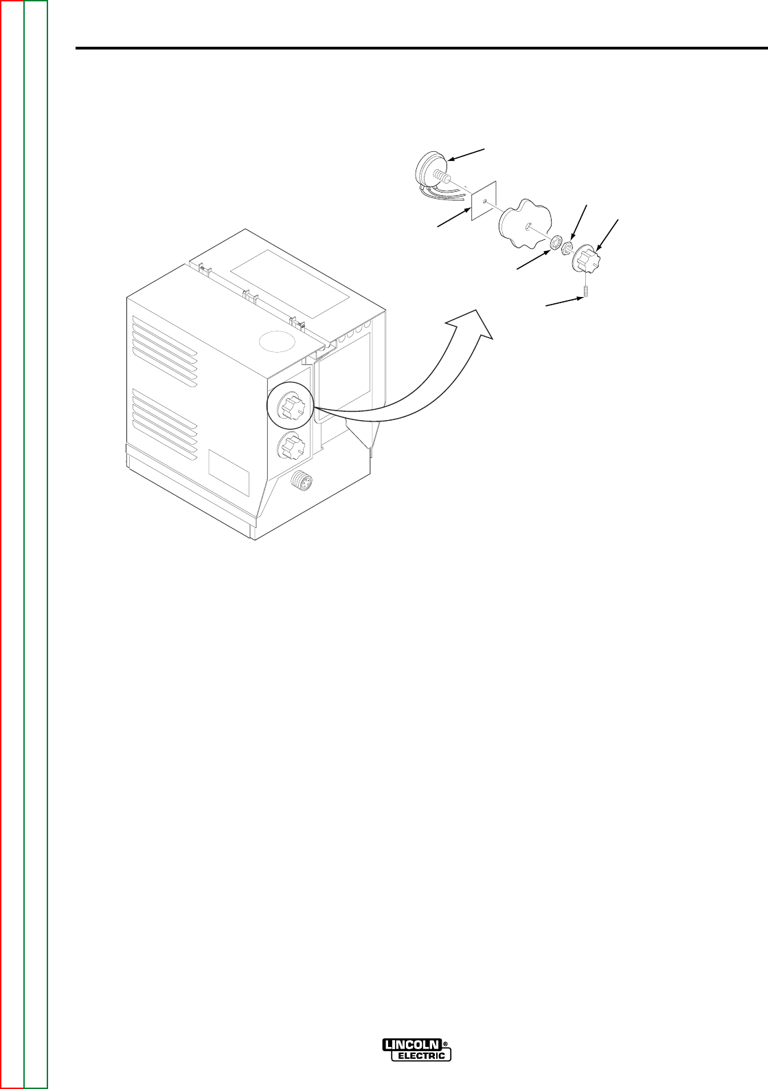
F-25
TROUBLESHOOTING AND REPAIR
F-25
REPAIR PROCEDURE
1. Remove input power to the LN-8
2. Using the 5/16 in. nutdriver,
remove the screws from the left
side cover assembly.
3. Using a 5/64 in. Allen wrench or
slothead screwdriver, loosen the
setscrew on the potentiometer knob
and remove the knob from the
potentiometer. Refer to Figure F.7.
4. Remove the nut and lockwasher
holding the potentiometer to the
left side cover assembly.
5. Remove the potentiometer and
insulation sheet from the inside of
the left side cover assembly.
6. Tag the three wires on the poten-
tiometer so that they can be reat-
tached in the same location from
where they were removed.
Unsolder the three wires from the
potentiometer.
7. Solder the three wires to the new
potentiometer on the correspond-
ing terminals from where they were
removed.
8. Place the new potentiometer and
insulation sheet through the cover
assembly from the inside. Ensure
that the index pin in the poten-
tiometer fits in the locating hole on
the cover assembly. Install the
lockwasher and nut on the poten-
tiometer. Tighten the nut until it is
snug.
9. Install the knob onto the poten-
tiometer so the set screw aligns
with the flat on the potentiometer.
Tighten the set screw.
10. Install the screws that secure the
left side cover assembly.
POTENTIOMETER REPLACEMENT (continued)
FIGURE F.7 – POTENTIOMETER REMOVAL
LN-8
Return to Section TOC Return to Section TOC Return to Section TOC Return to Section TOC
Return to Master TOC Return to Master TOC Return to Master TOC Return to Master TOC
POTENTIOMETER
NUTKNOB
LOCKWASHER
SET
SCREW
INSULATION

Return to Section TOC Return to Section TOC Return to Section TOC Return to Section TOC
Return to Master TOC Return to Master TOC Return to Master TOC Return to Master TOC
F-26
TROUBLESHOOTING AND REPAIR
F-26
LN-8
MATERIALS NEEDED
5/16 in. nutdriver
9/16 in. wrench
CIRCUIT BREAKER REPLACEMENT
Service and repair should be performed only by Lincoln Electric factory trained per-
sonnel. Unauthorized repairs performed on this equipment could result in danger to
the technician or the machine operator and will invalidate your factory warranty. For
your safety and to avoid electrical shock, please observe all safety notes and precau-
tions detailed throughout this manual.
If for any reason you do not understand the test procedures or are unable to perform
the tests/repairs safely, contact the Lincoln Electric service department for technical
troubleshooting assistance before you proceed.
Call (800) 833-9353 (WELD).
_____________________________________________________________
WARNING
This procedure takes approximately 6 minutes to perform.
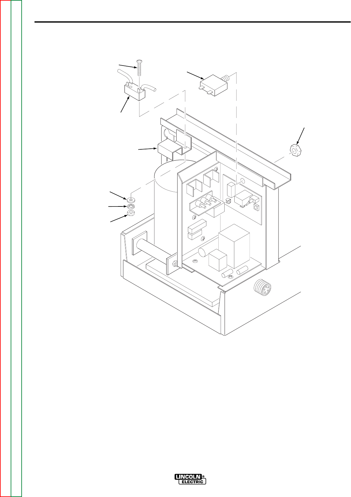
F-27
TROUBLESHOOTING AND REPAIR
F-27
REPAIR PROCEDURE
1. Using the 5/16 in. nutdriver,
remove the screws from the left
side cover assembly.
2. Tag and remove the two connec-
tors from the back of the circuit
breaker. Refer to Figure F.8.
3. Using the 9/16 in. wrench, remove
the retaining nut that secures the
circuit breaker to the center panel
on the wire feeder. Remove the
circuit breaker from the wire
feeder.
4. Install the new circuit breaker
through the panel of the control
box. Secure the circuit breaker
with the retaining nut.
5. Install the connectors onto the
back of the circuit breaker at the
positions they were removed from.
6. Install the screws that secure the
left side cover assembly.
CIRCUIT BREAKER REPLACEMENT (continued)
FIGURE F.8 – CIRCUIT BREAKER AND GROUND LEAD PROTECTOR REPLACEMENT
LN-8
Return to Section TOC Return to Section TOC Return to Section TOC Return to Section TOC
Return to Master TOC Return to Master TOC Return to Master TOC Return to Master TOC
CIRCUIT
BREAKER
SCREW
GROUND LEAD
PROTECTOR SWITCH
SWITCH
MOUNT
FLATWASHER
LOCKWASHER
NUT
RETAINING
NUT

Return to Section TOC Return to Section TOC Return to Section TOC Return to Section TOC
Return to Master TOC Return to Master TOC Return to Master TOC Return to Master TOC
F-28
TROUBLESHOOTING AND REPAIR
F-28
LN-8
MATERIALS NEEDED
5/16 in. nutdriver
3/32 in. wrench
Jewelers’ flat blade screwdriver
Soldering iron and solder
GROUND LEAD PROTECTOR PUSH BUTTON
SWITCH REPLACEMENT
Service and repair should be performed only by Lincoln Electric factory trained per-
sonnel. Unauthorized repairs performed on this equipment could result in danger to
the technician or the machine operator and will invalidate your factory warranty. For
your safety and to avoid electrical shock, please observe all safety notes and precau-
tions detailed throughout this manual.
If for any reason you do not understand the test procedures or are unable to perform
the tests/repairs safely, contact the Lincoln Electric service department for technical
troubleshooting assistance before you proceed.
Call (800) 833-9353 (WELD).
_____________________________________________________________
WARNING
This procedure takes approximately 10 minutes to perform.

Return to Section TOC Return to Section TOC Return to Section TOC Return to Section TOC
Return to Master TOC Return to Master TOC Return to Master TOC Return to Master TOC
F-29
TROUBLESHOOTING AND REPAIR
F-29
REPAIR PROCEDURE
1. Using the 5/16 in. nutdriver,
remove the screws from the left
side cover assembly.
2. Using the 3/32 in. wrench and jew-
elers’ flat blade screwdriver,
remove the ground lead protector
switch from the switch mount.
Refer to Figure F.8.
3. Remove insulation and unsolder
the two leads from the ground lead
protector switch.
4. Solder the two leads onto the
new switch and reinsulate the
connections.
5. Place the switch onto the switch
mount and install the screws, flat
washers, lockwashers and nuts
that secure the switch into place.
6. Install the screws that secure the
left side cover assembly.
LN-8
GROUND LEAD PROTECTOR PUSH BUTTON
SWITCH REPLACEMENT (continued)

Return to Section TOC Return to Section TOC Return to Section TOC Return to Section TOC
Return to Master TOC Return to Master TOC Return to Master TOC Return to Master TOC
F-30
TROUBLESHOOTING AND REPAIR
F-30
LN-8
MATERIALS NEEDED
5/16 in. nutdriver
Flat blade screwdriver
Needlenose pliers
TRIGGER TRANSFORMER REPLACEMENT
Service and repair should be performed only by Lincoln Electric factory trained per-
sonnel. Unauthorized repairs performed on this equipment could result in danger to
the technician or the machine operator and will invalidate your factory warranty. For
your safety and to avoid electrical shock, please observe all safety notes and precau-
tions detailed throughout this manual.
If for any reason you do not understand the test procedures or are unable to perform
the tests/repairs safely, contact the Lincoln Electric service department for technical
troubleshooting assistance before you proceed.
Call (800) 833-9353 (WELD).
_____________________________________________________________
WARNING
This procedure takes approximately 12 minutes to perform.
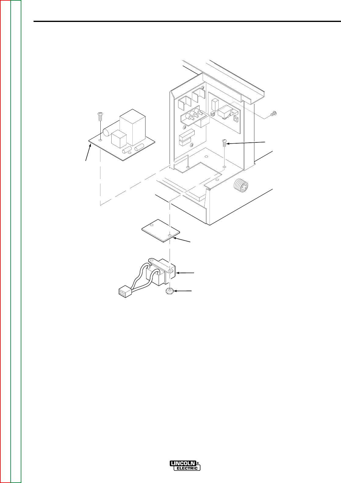
Return to Section TOC Return to Section TOC Return to Section TOC Return to Section TOC
Return to Master TOC Return to Master TOC Return to Master TOC Return to Master TOC
F-31
TROUBLESHOOTING AND REPAIR
F-31
REPAIR PROCEDURE
1. Using the 5/16 in. nutdriver
remove the screws from the left
side cover assembly.
2. Remove the Relay PC board as
described in the PC Board
Replacement procedure.
3. Disconnect the Molex plug for the
trigger transformer from the bottom
of the relay board. Refer to Figure
F.9.
4. Using a flat blade screwdriver and
needlenose pliers, remove the trig-
ger transformer and insulation
sheet from the case.
5. Place the insulation sheet and new
trigger transformer into the case
and install the screws and nuts
that secure the transformer in
place.
6. Install the Relay PC board as
described in the PC Board
Replacement procedure.
7. Attach the trigger transformer
Molex plug to the bottom of the
relay board.
8. Install the screws that secure the
left side cover assembly.
LN-8
TRIGGER TRANSFORMER REPLACEMENT (continued)
FIGURE F.9 – TRIGGER TRANSFORMER REMOVAL
INSULATION
SHEET
TRIGGER
TRANSFORMER
RELAY
PC BOARD
ROUNDHEAD
SCREW
NUT

Return to Section TOC Return to Section TOC Return to Section TOC Return to Section TOC
Return to Master TOC Return to Master TOC Return to Master TOC Return to Master TOC
F-32
TROUBLESHOOTING AND REPAIR
F-32
LN-8
MATERIALS NEEDED
5/16 in. nutdriver
Phillips screwdriver
PC BOARD REPLACEMENT
Service and repair should be performed only by Lincoln Electric factory trained per-
sonnel. Unauthorized repairs performed on this equipment could result in danger to
the technician or the machine operator and will invalidate your factory warranty. For
your safety and to avoid electrical shock, please observe all safety notes and precau-
tions detailed throughout this manual.
If for any reason you do not understand the test procedures or are unable to perform
the tests/repairs safely, contact the Lincoln Electric service department for technical
troubleshooting assistance before you proceed.
Call (800) 833-9353 (WELD).
_____________________________________________________________
WARNING
The Variable Voltage board takes approximately 5 minutes to replace.
The Control board takes approximately 5 minutes to replace.
The Relay board takes approximately 5 minutes to replace.
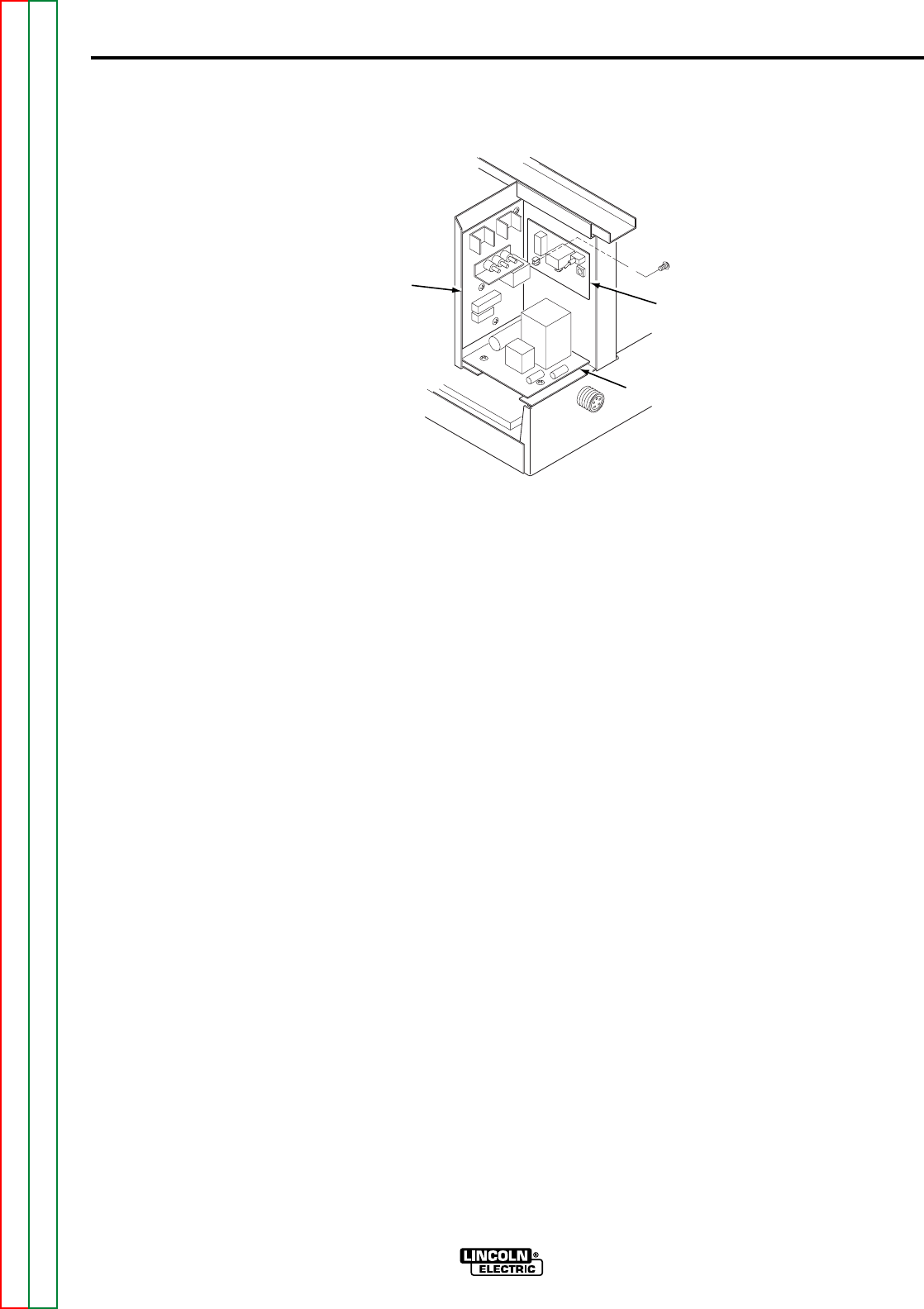
Return to Section TOC Return to Section TOC Return to Section TOC Return to Section TOC
Return to Master TOC Return to Master TOC Return to Master TOC Return to Master TOC
F-33
TROUBLESHOOTING AND REPAIR
F-33
REPAIR PROCEDURE
1. Observe the static precautions
detailed in the PC Board
Troubleshooting Procedures at
the beginning of this section.
2. Using the 5/16 in. nutdriver,
remove the screws from the left
side cover assembly.
CAUTION: Label all wires and connec-
tors prior to removal. All wires and con-
nectors must be reconnected to the
same terminals from where they were
removed. Improper connection may
lead to component damage or machine
malfunction.
VARIABLE VOLTAGE BOARD
REMOVAL AND REPLACEMENT
1. Disconnect all plugs and connec-
tors that can be reached without
removing the variable voltage PC
board. Refer to Figure F.10.
2. Using a Phillips screwdriver,
remove the screws that secure the
variable voltage PC board to the
case.
NOTE: The screws that secure the
Variable Voltage PC board are on the
wire drive assembly side of the unit.
3. Carefully move the PC board away
from the case, checking to ensure
that all plugs and connectors have
been removed. Disconnect any
connectors that have been missed
or that could not be reached while
the PC board was installed.
4. Place the new PC board into the
case and install the mounting
screws.
5. Connect all plugs and connectors
to the PC board in the same loca-
tion they were removed from.
6. Install the screws that secure the
left side cover assembly.
LN-8
PC BOARD REPLACEMENT (continued)
FIGURE F.10 – PC BOARD LOCATIONS
VARIABLE
VOLTAGE
PC BOARD
CONTROL
PC BOARD
RELAY
PC BOARD

Return to Section TOC Return to Section TOC Return to Section TOC Return to Section TOC
Return to Master TOC Return to Master TOC Return to Master TOC Return to Master TOC
F-34
TROUBLESHOOTING AND REPAIR
F-34
RELAY BOARD REMOVAL AND
REPLACEMENT
1. If the Relay PC board is being
replaced, remove the 1CR Relay
from the PC board.
2. Disconnect all plugs and connec-
tors.
3. Remove mounting screws.
4. Place the new PC board into the
case and install the mounting
screws.
5. Install the 1CR Relay into the PC
board.
CAUTION: Do not use excessive force
when installing the 1CR Relay.
Excessive force can damage the Relay
PC board. If the relay does not fit prop-
erly, remove it and try again.
6. Connect all plugs and connectors
to the PC board in the same loca-
tion they were removed from.
7. Install the screws that secure the
left side cover assembly.
CONTROL PC BOARD
REMOVAL AND
REPLACEMENT
1. Disconnect all plugs and connec-
tors from the Control PC board.
2. Using a Phillips screwdriver,
remove the screws that secure the
Control PC board to the case.
3. Carefully move the Control Board
away from the case. Check to
ensure that all plugs and connec-
tors have been disconnected.
4. Place the new PC board into the
case and install the mounting
screws.
5. Connect all plugs and connectors
to the PC board in the same loca-
tion they were removed from.
6. Install the screws that secure the
left side cover assembly.
LN-8

Return to Section TOC Return to Section TOC Return to Section TOC Return to Section TOC
Return to Master TOC Return to Master TOC Return to Master TOC Return to Master TOC
F-35
TROUBLESHOOTING AND REPAIR
F-35
LN-8
MATERIALS NEEDED
Offset flat blade screwdriver
Flat blade screwdriver
Phillips screwdriver
7/16 in. wrench
1/2 in. wrench
11/32 in. wrench
Insulating tape
WIRE DRIVE ASSEMBLY AND COMPONENT REPLACEMENT
Service and repair should be performed only by Lincoln Electric factory trained per-
sonnel. Unauthorized repairs performed on this equipment could result in danger to
the technician or the machine operator and will invalidate your factory warranty. For
your safety and to avoid electrical shock, please observe all safety notes and precau-
tions detailed throughout this manual.
If for any reason you do not understand the test procedures or are unable to perform
the tests/repairs safely, contact the Lincoln Electric service department for technical
troubleshooting assistance before you proceed.
Call (800) 833-9353 (WELD).
_____________________________________________________________
WARNING
This procedure takes approximately 40 minutes to perform.
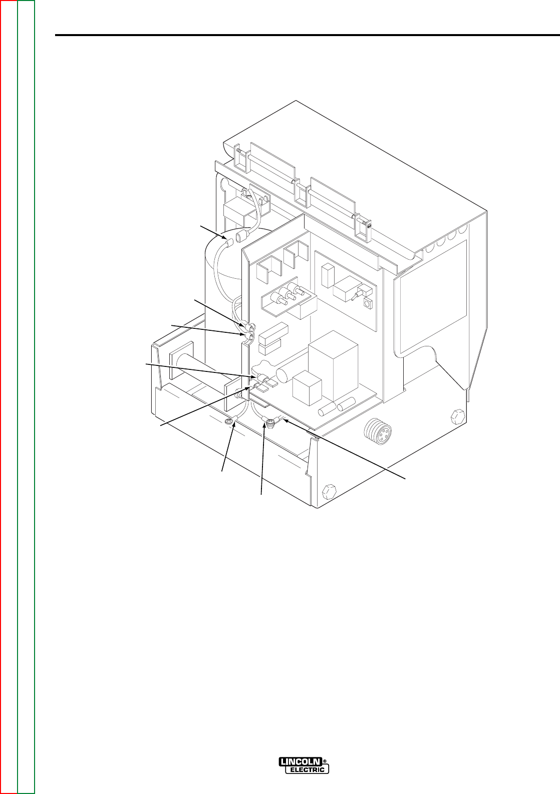
Return to Section TOC Return to Section TOC Return to Section TOC Return to Section TOC
Return to Master TOC Return to Master TOC Return to Master TOC Return to Master TOC
F-36
TROUBLESHOOTING AND REPAIR
F-36
REPAIR PROCEDURE
1. Using the 5/16 in. nutdriver,
remove the screws from the left
side cover assembly.
2. Disconnect drive motor leads #539
(blue) and #541 (black) from the
back of the Control PC board.
Refer to Figure F.11.
3. Disconnect drive motor leads #626
(red) and #627 (white) from the
side of the Relay PC board.
4. Using a Phillips screwdriver, dis-
connect the drive motor ground
lead (green) from the case.
5. Separate ground lead protection
wire #525 (yellow) at the in-line
connector.
6. Remove the insulating tape from
wire #528 (yellow) and disconnect
it from the reed switch wire and
gun receptacle wire (#528, and
both blue leads) using a 11/32 in.
wrench and a Phillips screwdriver.
See the wiring diagram.
LN-8
WIRE DRIVE ASSEMBLY AND COMPONENT REPLACEMENT (continued)
FIGURE F.11 – DRIVE MOTOR ELECTRICAL CONNECTIONS
YELLOW
(#525)
BLACK
(#541)
BLUE
(#539)
WHITE
(#627)
RED
(#626)
GREEN
(GROUND)
YELLOW
(#528)
BLUE (TWO)
(#528)
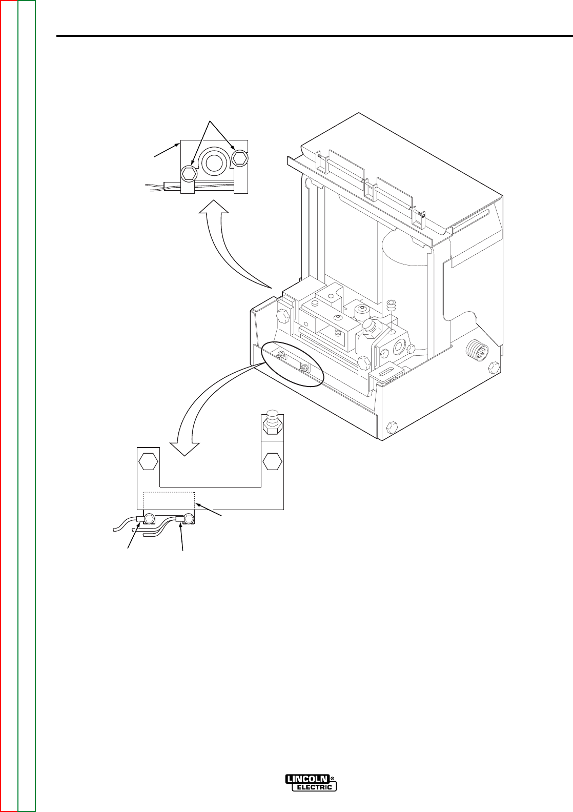
Return to Section TOC Return to Section TOC Return to Section TOC Return to Section TOC
Return to Master TOC Return to Master TOC Return to Master TOC Return to Master TOC
F-37
TROUBLESHOOTING AND REPAIR
F-37
7. Disconnect two leads #567 (blue),
and lead #568 (blue) from the
shunt using the 11/32 in. wrench.
See Figure F.12. Note the lead
placement on the shunt for
reassembly.
8. Using a 7/16 in. wrench, loosen
the two hex head screws that
secure the reed switch bracket to
the front of the wire drive assem-
bly. Slide the bracket off the front
of the wire drive assembly.
9. Using an offset flat blade screw-
driver, remove the two mounting
screws below the shunt and the
one mounting screw below the
wire drive motor. Remove the wire
drive assembly through the wire
drive side of the case.
LN-8
WIRE DRIVE ASSEMBLY AND COMPONENT REPLACEMENT (continued)
FIGURE F.12 – REED SWITCH REMOVAL AND SHUNT ELECTRICAL CONNECTIONS
SHUNT
#567
#568
REED
SWITCH
BRACKET
HEX HEAD
SCREWS
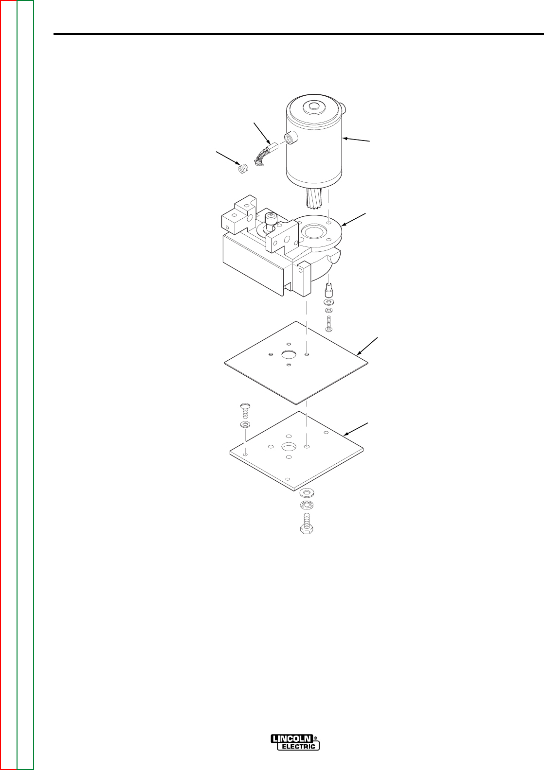
Return to Section TOC Return to Section TOC Return to Section TOC Return to Section TOC
Return to Master TOC Return to Master TOC Return to Master TOC Return to Master TOC
F-38
TROUBLESHOOTING AND REPAIR
F-38
10. Using a 1/2 in. wrench, remove the
four hex head screws, lockwash-
ers and flat washers that hold the
mounting plate to the gear box
assembly, and remove the mount-
ing plate and insulation sheet.
Refer to Figure F.13.
11. Using a flat blade screwdriver,
remove the three screws, lock-
washers, flat washers and spacers
that secure the drive motor to the
gearbox assembly, and remove
the drive motor.
12. For further disassembly of the wire
drive assembly, refer to Figure
F.13.
13. Secure the drive motor to the gear-
box assembly using three screws,
lockwashers, flat washers, and
spacers.
LN-8
WIRE DRIVE ASSEMBLY AND COMPONENT REPLACEMENT (continued)
FIGURE F.13 – WIRE DRIVE ASSEMBLY REMOVAL
BRUSH
SCREW
BRUSH
WIRE
DRIVE
MOTOR
GEARBOX
INSULATION
SHEET
MOUNTING
PLATE

F-39
TROUBLESHOOTING AND REPAIR
F-39
14. Install the gearbox assembly onto
the insulation sheet and mounting
plate using four hex head screws,
lockwashers and flat washers.
Ensure that the edge of the mount-
ing plate that has the single
mounting hole is under the drive
motor.
15. Place the wire drive assembly into
the case. Secure the wire drive
assembly using three round head
screws and lockwashers.
16. Position the reed switch bracket
onto the front of the wire drive
assembly and tighten the two hex
head screws that secure it in
place. Refer to Figure F.12.
17. Connect the two #567 (blue) leads
and the #568 (blue) lead to the
shunt. Note lead placement. Refer
to Figure F.13.
18. Connect the #528 wire (yellow)
from the drive motor to the reed
switch wire and gun receptacle
wire (both #528 blue) using the
round head screw and nut. Wrap
the connection in insulating tape.
Refer to Figure F.11.
19. Connect the drive motor wire #525
(yellow) to the ground lead protec-
tion wire at the in-line connector.
20. Connect the drive motor ground
lead (green) to the case.
21. Connect the drive motor leads
#539 (blue) and #541 (black) to
the back of the Control PC board.
22. Connect drive motor leads #626
(red) and #627 (white) to the side
of the Relay PC board.
23. Install the screws that secure the
left side cover assembly.
WIRE DRIVE ASSEMBLY AND COMPONENT REPLACEMENT (continued)
LN-8
Return to Section TOC Return to Section TOC Return to Section TOC Return to Section TOC
Return to Master TOC Return to Master TOC Return to Master TOC Return to Master TOC

F-40
TROUBLESHOOTING AND REPAIR
F-40
If a failed test indicates that any
mechanical part that could affect the
machine’s electrical characteristics
must be replaced or if any electrical
components are repaired or replaced,
the machine must be retested and meet
the following standards.
RETEST AFTER REPAIR
LN-8
Return to Section TOC Return to Section TOC Return to Section TOC Return to Section TOC
Return to Master TOC Return to Master TOC Return to Master TOC Return to Master TOC
Wire Feed Speed Range . . . . . . . . . . . . . . . . . . . . . . . . . . . . . . . . . . . 50 to 600 IPM
Gas Solenoid (If Used) . . . . . . . . . . . . . Must function when gun trigger is activated.
1CR Relay . . . . . . . . . . . . . . . . . . . . . . Must function when gun trigger is activated.
2CR Reed Switch . . . . . . . . . . . . . . . . . Must close when welding current is present.

G-1
ELECTRICAL DIAGRAMS
G-1
Return to Master TOC Return to Master TOC Return to Master TOC Return to Master TOC
TABLE OF CONTENTS
-ELECTRICAL DIAGRAMS SECTION-
Electrical Diagrams . . . . . . . . . . . . . . . . . . . . . . . . . . . . . . . . . . . . . . . . . . . . . . . . . . . . . . . . Section G
Wiring Diagram. . . . . . . . . . . . . . . . . . . . . . . . . . . . . . . . . . . . . . . . . . . . . . . . . . . . . . . . . . G-2
Connection Schematic . . . . . . . . . . . . . . . . . . . . . . . . . . . . . . . . . . . . . . . . . . . . . . . . . . . . G-3
Operating Schematic . . . . . . . . . . . . . . . . . . . . . . . . . . . . . . . . . . . . . . . . . . . . . . . . . . . . . G-4
Control Board (L5767) Schematic . . . . . . . . . . . . . . . . . . . . . . . . . . . . . . . . . . . . . . . . . . . G-5
Variable Voltage Board (L5039) Schematic . . . . . . . . . . . . . . . . . . . . . . . . . . . . . . . . . . . . G-6
Control Board (L5767) Layout . . . . . . . . . . . . . . . . . . . . . . . . . . . . . . . . . . . . . . . . . . . . . . G-7
Variable Voltage Board (L5039) Layout . . . . . . . . . . . . . . . . . . . . . . . . . . . . . . . . . . . . . . . G-8
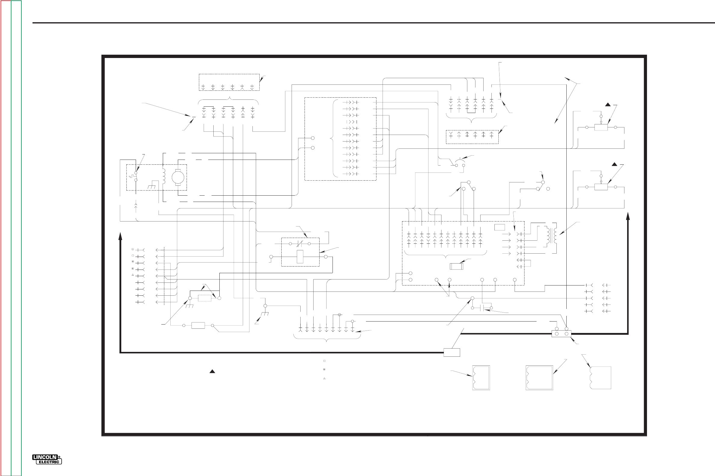
G-2
ELECTRICAL DIAGRAMS
LN-8
Wiring Diagram
2502 4504 53132A
*
162345
2502 4504 53132A
528
525
WIRE
FEED
MOTOR
539 U
541 B
R
626
627 W
BURNBACK P.C. BOARD
JUMPER CONNECTOR IS REMOVED
AND CONNECTOR "B" PLUGGED
INTO OPTIONAL BURNBACK
P.C. BOARD.
CONNECTOR "B"
THERMAL CIRCUIT
BREAKER
G
A2
4
31
32
21
75
76
77
B
C
D
E
F
G
H
I
GND
31 531
2 OHMS
634
632
631
635
636
637
32A
543
541
32A
7
3
4
9
1
6
7
12
10
5
11
2
8
*
CONTROL
P.C.
BOARD
541
539
GROUNDING
LEAD
PROTECTOR
525A 4CR
525
289571436
*
GND
21
541 543
568
567
504531531
50232A
10 411 1 89
7
56
627
683
682
536
37212
*
RELAY
P.C. BOARD
627
626
32A 7
526
531A
32A
522
1CR
4
2
3
1
6
5
524525A
529
R
B
R
B
682
683
627
DIRECTION
OF WIRE
FEED
SWITCH
32A
32
5 AMP CIRCUIT BREAKER
523 ON OFF
536
INTERLOCK SWITCH
BEAD PINS ON
BOTTOM OF BOARD
21 635636 637567
*
1/ AMP 125V.2
OR 250V. SLOW
BLOW FUSE
124563
21 635 636 637567
CONNECTOR "A"
VARIABLE VOLTAGE
P.C. BOARD
(OPTIONAL)
632
634 5K OHMS 631
10K OHMS
76
75 77
POWER SOURCE
OUTPUT
RHEOSTAT
SPEED
RHEOSTAT
WIRE FEED
LOW VOLTAGE
TRIGGER
TRANSFORMER
QUICK CONNECT TERMINALS 7 & 32A
TO CONNECT AUXILIARY EQUIPMENT
OPTIONAL METER
KIT RECEPTACLE
528 529 2CR REED SWITCH
528
524 A
B
C
D
E
GUN CABLE
567
568
ELECTRODE TO POWER SOURCE
METER SHUNT
WORK TO POWER SOURCE
WORK
BOLTED
CONNECTION
LEAD COLOR CODING
B = BLACK
G = GREEN
R = RED
W = WHITE
U = BLUE
ELECTRICAL SYMBOLS PER E1537
*CONNECTOR CAVITY NUMBER
CONNECTIONS AS VIEWED FROM
BACK OF RHEOSTATS WHEN
COVER IS UP
TO CONTACTOR CIRCUIT
115 VAC
TO POWER SOURCE WORK
TERMINAL 1
2
3
47
58
69
METER KIT
RECEPTACLE
PIN SIDE OF
CONNECTOR
14710
25811
36912
RELAY AND
CONTROL BOARD
14
25
6
3
CAVITY NUMBERING SEQUENCE
(COMPONENT SIDE OF BOARD)
BURNBACK
AND VARIABLE
VOLTAGE BOARD
2-1-2002M
M14679
LN-8N, -8NE, -8S, AND -8SE WIRING DIAGRAM
JUMPER CONNECTOR IS REMOVED AND CONNECTOR
"A" PLUGGED INTO OPTIONAL VARIABLE VOLTAGE
POWER SOURCE BOARD.
(OPTIONAL)
J1
N.B.
523
GND
G
SCREW
CASE
GROUNDING
.1 OHMS
N.A.
CASE
GROUNDING
SCREW
NOTES:
N.A. RESISTOR USED ON CODES 9090 AND BELOW. FOR CODES ABOVE 9090
THE GROUNDING LEAD PROTECTOR CONNECTS DIRECTLY TO THE CASE
GROUNDING SCREW.
N.B. THE VARIABLE VOLTAGE BOARD IS FACTORY INSTALLED IN CV-VV MODELS
AND DOES NOT INCLUDE JUMPER CONNECTOR.
115 V.A.C., .25 AMP RATING
WW
W
G-2
Return to Section TOC Return to Section TOC Return to Section TOC Return to Section TOC
Return to Master TOC Return to Master TOC Return to Master TOC Return to Master TOC
NOTE: This diagram is for reference only. It may not be accurate for all machines covered by this manual.
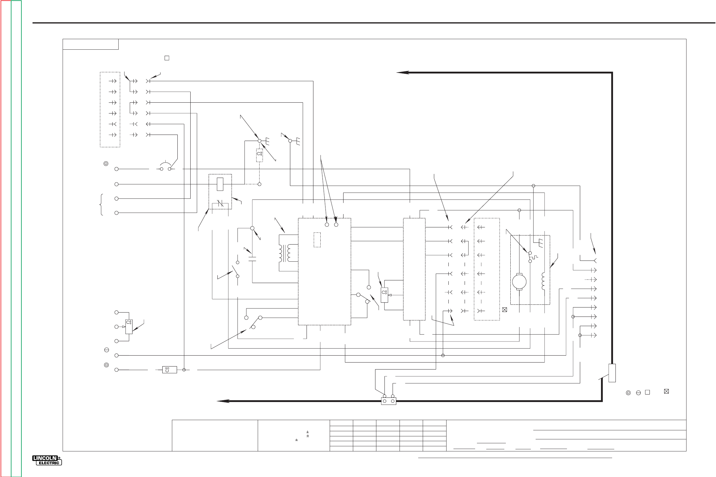
G-3
ELECTRICAL DIAGRAMS
LN-8
CONNECTION SCHEMATIC
14669
Ch’ge. Sht. No.
3-31-83N
11-14-86G
2-13-87G
t
UNLESS OTHERWISE SPECIFIED TOLERANCE
ON HOLE SIZES PER E2056
ON 2 PLACE DECIMALS IS .02
WITH PUBLISHED STANDARDS.
ON 3 PLACE DECIMALS IS .002
ON ALL ANGLES IS .5 OF A DEGREE
MATERIAL TOLERANCE (" ") TO AGREE
THE LINCOLN ELECTRIC CO.
CLEVELAND, OHIO U.S.A.
EQUIP.
TYPE
SCALE SUBJECT
DR DATE CHK REF. SUP’S’D’G
SHT.
NO.
THE LINCOLN ELECTRIC CO.
THIS SHEET CONTAINS PROPRIETARY INFORMATION
OWNED BY AND IS
NOT TO BE REPRODUCED, DISCLOSED OR USED
THE LINCOLN ELECTRIC CO.
M
M
WITHOUT THE EXPRESS PERMISSION OF
14669
3-4-83
NONE
FI 6-20-97
LN-8N AND -8S
CONNECTION SCHEMATIC
568
567
63418759
21
543
GND
568
567
2
541
ARM
539
525
627 626
528
541
THERMAL CIRCUIT BREAKER
21 567 635 636 637
VARIABLE VOLTAGE P.C. BD. (OPTIONAL)
21 567 635 636 637
631 632 634 32A 7
635 636 637
541
32A
CONTROL P.C. BD.
REV.
FWD.
7
32A
683 627 682
RELAY
P.C. BOARD
626
32A
7
536
523
525A
529
526
531A
32A
522
LOW VOLTAGE
TRIGGER TRANSFORMER
2CR REED SWITCH
ON
OFF
627
531
524
502 504
32A 531 24
115 V.A.C. (31 AND 32)
TO POWER SOURCE WORK TERMINAL
JUMPER CONNECTOR IS REMOVED AND CONNECTOR "B" IS PLUGGED
INTO OPTIONAL BURNBACK P.C. BOARD
ACTUATED BY MOTOR TEMPERATURE
ELECTRICAL SYMBOLS PER E1537
WORK
METER KIT
RECEPTACLE
WIRE FEED
MOTOR
504
502
METER
SHUNT
ELECTRODE TO POWER SOURCE
10K
31 21 75 76 77
31
531
2
POWER SOURCE
OUTPUT CONTROL
INTERLOCK
SWITCH GUN TRIGGER
SWITCH
524 528
525A
525
4CR
.1
QUICK CONNECT TERMINALS ON
BOARD FOR CONNECTION OF
AUXILIARY EQUIPMENT 115 V.A.C.
JUMPER CONNECTOR IS REMOVED AND
CONNECTOR "A" PLUGGED INTO
OPTIONAL VARIABLE VOLTAGE POWER
SOURCE BOARD.
FACTORY INSTALLED IN CV-VV
THE VARIABLE VOLTAGE BOARD IS
MODELS AND DOES NOT INCLUDE
JUMPER CONNECTOR.
JUMPER CONNECTOR
WORK TO POWER SOURCE
CONNECTOR "A"
543
539
5K
WIRE FEED
SPEED
CONTROL
DIRECTION
OF WIRE
FEED SWITCH
1CR
CASE GROUNDING
SCREW
502 504
4
531
32A 2
5 AMP
CIRCUIT
BREAKER
BURNBACK
P.C. BOARD (OPTIONAL)
24GND 32
TO POWER SOURCE
TO OPERATE CONTACTOR
32
32A
JUMPER
CONNECTOR
CONNECTOR
"B"
BOLTED
CONNECTION
RESISTOR USED ON CODES
9090 AND BELOW ONLY.
THE GROUNDING LEAD
PROTECTOR CONNECTS
DIRECTLY TO THE CASE
GROUNDING SCREW.
GROUND LEAD PROTECTOR
FOR CODES ABOVE 9090
.25 AMP RATING
G-3
Return to Section TOC Return to Section TOC Return to Section TOC Return to Section TOC
Return to Master TOC Return to Master TOC Return to Master TOC Return to Master TOC
NOTE: Lincoln Electric assumes no responsibility for liablilities resulting from board level troubleshooting. PC Board repairs will invalidate your factory warranty. Individual Printed Circuit Board Components are not available from Lincoln Electric. This information is provided
for reference only. Lincoln Electric discourages board level troubleshooting and repair since it may compromise the quality of the design and may result in danger to the Machine Operator or Technician. Improper PC board repairs could result in damage to the machine.
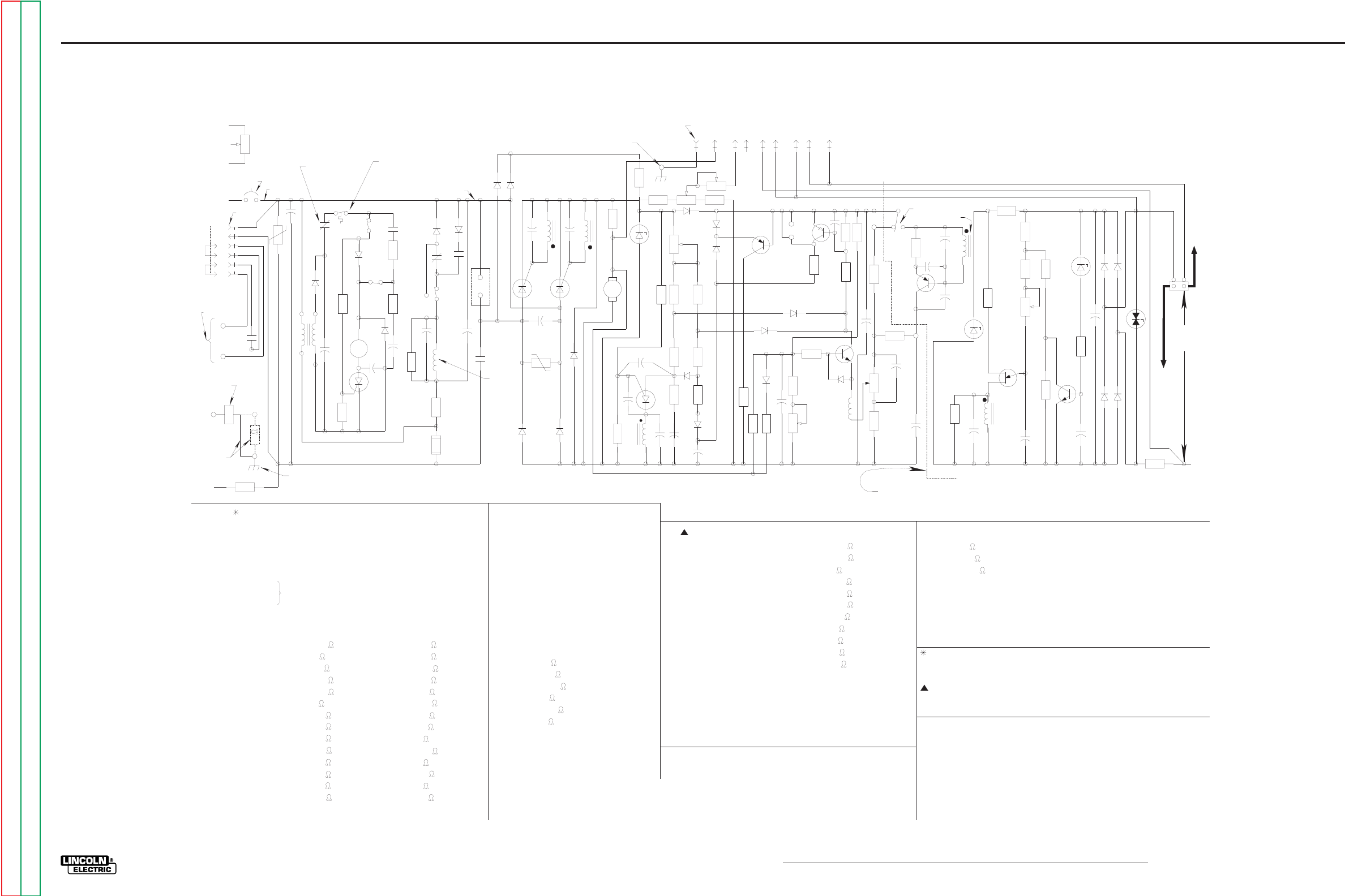
G-4
ELECTRICAL DIAGRAMS
LN-8
OPERATING SCHEMATIC
5
4
2
3
6
1
32A
531
4
504
502
2
2
4
1CR
504
N.A.
32
32A
5 AMP CIRCUIT
BREAKER
TP201
C204
77
76
75
R20
T1
526 525A
C205
525
R205
523
524
S1
R204
S2
536
R202
D205
529
2CR
528
D204
1CR
C201
R206
SCR
531
C202
R203
C203
(R)
(W)
627
S3
683
682
1CR
D201
D202
C206
R201
626
F201
531
1CR
32A
732A
D103 D104
C107
PT101
C109
7
TP101
SCR101 SCR102
C108
PT101
D107
D105
D106
539
R123
541
(B)
(U)
R118
DZ101
R105
R127
R111
R109
R113
C105
C106
PT101
R106
C112
QU101
R107
R129
D113
C103 D102
R108
R112
C111
D101
D114
D108
539
R125
R124
R126
R128
R119
R120
D111
Q103
D110
S
F
Q101
R114
D109
R116
R117
C113
635
R115
C104
R102 R121
Q102
R122
D112
L101
R103
R110 R9
632
631
C110
634
R101
C102
A
B
CV VV
S304
R309
C306
Q302
C305 C303
DZ302
R310
C304
PT301
C302
R306
R302
QU301
R308 R305
R303
R304
Q301
C307
R301
DZ301
C301
D301
D302
D303
D304
TP301
R311
CONTROL CIRCUIT (BOARD #1)
C101
C102
C103
C104
C105
1MFD
2MFD
39MFD ~10%
4.7MFD
.10MFD
C106, C110,C111
C112, C113 .02 MFD
C107, C108 .047MFD
C109 .005MFD
D101
D102
D103
D104
D105
D106
D107
D108
D109
D110
D111
D112
D113
D114
1A.
1A.
1A.
1A.
16A.
1A.
1A.
1A.
1A.
1A.
1A.
1A.
20V.
16A.
16A.
DZ101
R101
R102
R103
R105
R106
R107
R108
R109
R110
R111
R112
R113
R114
R115
6.8K
10K
4.7K
4.7K
33K
33K
750
27K
39K
10K
68K
2K TRIMMER
15
50K TRIMMER
R116
R117
R118
R119
R120
R121
R122
R123
R124
R125
R126
R127
R128
R129
10K
22K
27K
15K
1.5K
10K
150
15K
4.7K 4W
.25 7W
1K TRIMMER
1K TRIMMER
1K
4.7K 4W
L101
Q101
Q102
Q103
QU101
TP101
SCR101
SCR102
PT101
5.6MH
2N4125
2N4123
2N5815
2N6027
TRANSIENT PROTECTION
12A 400V
12A 400V
1:1:1 PULSE TRANSFORMER
RELAY CIRCUIT (BOARD #2)
C201
C202
C203
C204
1CR
D201
50MFD
.02MFD
50MFD
.005MFD
C205
C206 .005MFD
50MFD
3PDT 24V.D.C.
1A.
D202
D203
D204
D205
1A.
1A.
1A.
1A.
R201 40 12W
R202
R203
R204
R205
R206
100
100K
27
4.7K
1K
F201 1/2A 125V CR 250V
SLOW BLOW FUSE
SCR201 4A 400V
TP201 TRANSIENT PROTECTION
VARIABLE VOLTAGE CIRCUIT (BOARD #3)
C301
C302
C303
C304
C305
C306, C307
2MFD
.10MFD
.01MFD
.047MFD
.01MFD
.02MFD
D301
D302
D303
D304
1A.
2A.
3A.
4A.
DZ301 62V
DZ302 10V
Q301
Q302
2N3393
2N4125
PT301 1:1:1 PULSE TRANSFORMER
TP301 TRANSIENT PROTECTION
R301
R302
R303
R304
R305
R306
R307
R308
R309
R310
R311
6.8K
3.3K
100
5.6K (2%)
1K (2%)
3.9K (2%)
4.7K 2W
5K TRIMMER
15
47
68
S304 POWER SOURCE
SELECTOR SWITCH
QU301 UJT
COMPONENTS NOT ON P.C. BOARD
R4
R9
T1
S1
S2
S3
R20
2CR
4CR
2 50W
5K 2W POT.
10K 2W POT.
110-24V TRANSFORMER
REED SWITCH (ACTUATED BY WELDING CURRENT)
GROUNDING LEAD PROTECTOR
SPST GUN SWITCH
SPDT INTERLOCK SWITCH
SPDT DIRECTION SWITCH
LEAD COLOR CODING
B - BLACK
W - WHITE
R - RED
U - BLUE
SINCE COMPONENTS OR CIRCUITRY ON A PRINTED CIRCUIT
BOARD MAY CHANGE WITHOUT AFFECTING THE INTER-
CHANGEABILITY OF A COMPLETE BOARD, THIS DIAGRAM
MAY NOT SHOW THE EXACT COMPONENTS OR CIRCUITRY
OF CONTROLS HAVING A COMMON CODE NUMBER.
GND LEAD
PROTECTOR
COIL
.1
R4
31
GND
N.B.
CASE GROUNDING
SCREW
FOR VARIABLE VOLTAGE P.C. BOARD L5039-1 OR HIGHER,
USE M16441 SCHEMATIC FOR COMPONENT VALUES AND
CIRCUIT CONNECTIONS
WIRE
FEED
MOTOR
FIELD
TO POWER
SOURCE TO
OPERATE
CONTACTOR
GND LEAD
PROTECTOR
SWITCH
THERMAL
CIRCUIT
BREAKERS
TH1
M16802 SCHEMATIC FOR COMPONENT VALUES AND
CIRCUIT CONNECTIONS
GND 541 543 567 568
21
CASE
GROUNDING
SCREW
N.A. JUMPER PLUG IS REMOVED AND CONNECTOR "B" IS PLUGGED INTO
OPTIONAL BURNBACK P.C. BOARD. SEE S15123 FOR OPERATING
SCHEMATIC.
N.B. RESISTOR USED ON CODES 9090 AND BELOW ONLY. FOR CODES
ABOVE 9090 THE GROUNDING LEAD PROTECTOR CONNECTS
DIRECTLY TO THE CASE GROUNDING SCREW.
VARIABLE VOLTAGE CONTROL CIRCUIT TO RIGHT OF THIS LINE. TO
OPERATE LN-8 WHEN THIS CIRCUIT IS NOT INSTALLED IN UNIT,
POINT "A" TO "B" IS JUMPERED.
PER E1537
ELECTRICAL SYMBOLS
METER KIT RECEPTACLE
PT301
21
POWER
SOURCE
TO
ARC
VOLTAGE
568
567
TO
GUN
CABLE
LN-8
SHUNT
D203
522
201
C101
R307
FOR CONTROL P.C. BOARDS L5767-1 AND HIGHER, USE
637
12-3-92E
M14680
G-4
Return to Section TOC Return to Section TOC Return to Section TOC Return to Section TOC
Return to Master TOC Return to Master TOC Return to Master TOC Return to Master TOC
NOTE: Lincoln Electric assumes no responsibility for liablilities resulting from board level troubleshooting. PC Board repairs will invalidate your factory warranty. Individual Printed Circuit Board Components are not available from Lincoln Electric. This information is provided
for reference only. Lincoln Electric discourages board level troubleshooting and repair since it may compromise the quality of the design and may result in danger to the Machine Operator or Technician. Improper PC board repairs could result in damage to the machine.
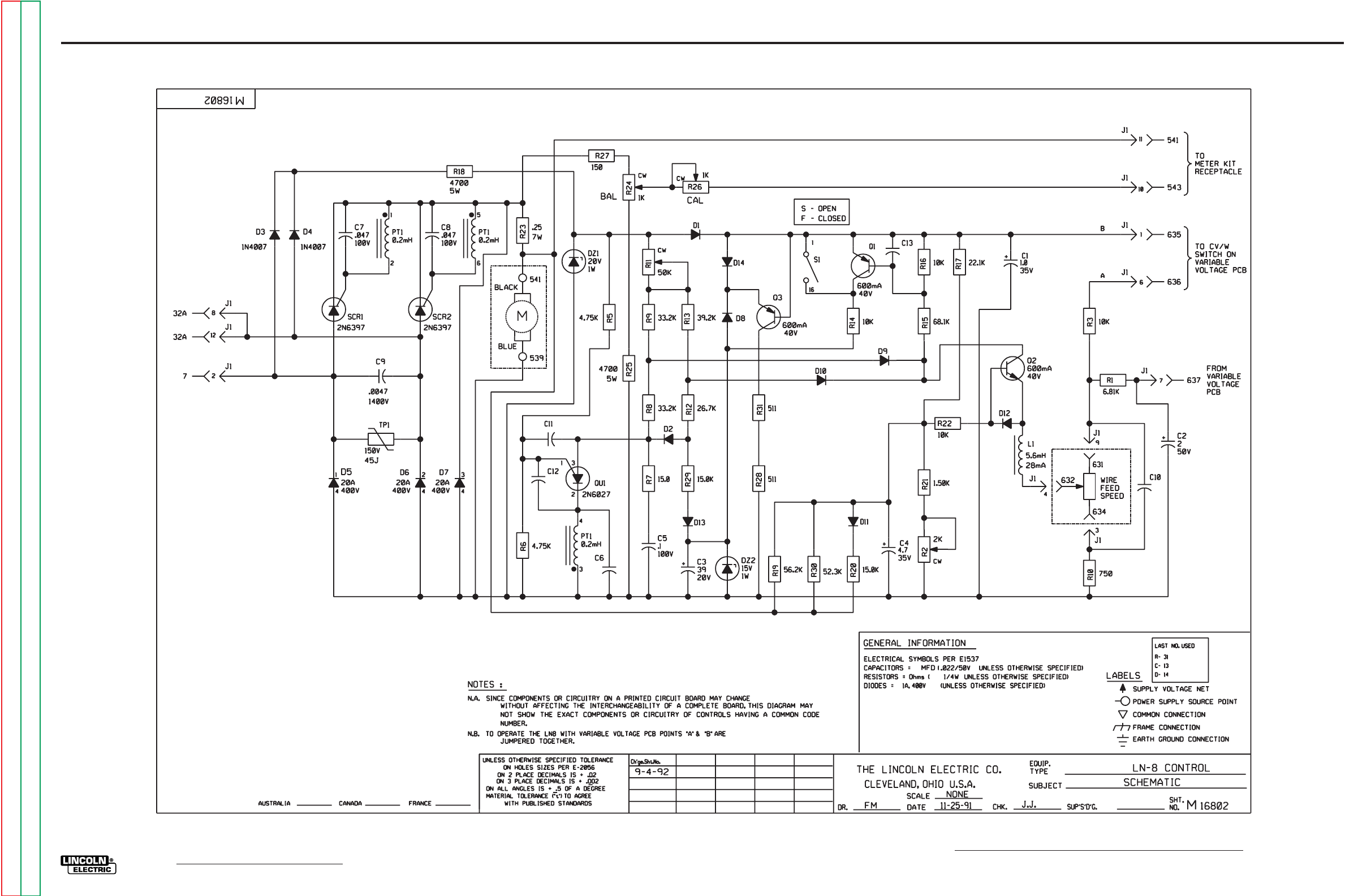
G-5
ELECTRICAL DIAGRAMS
LN-8
CONTROL BOARD (L5767) SCHEMATIC
G-5
Return to Section TOC Return to Section TOC Return to Section TOC Return to Section TOC
Return to Master TOC Return to Master TOC Return to Master TOC Return to Master TOC
NOTE: Lincoln Electric assumes no responsibility for liablilities resulting from board level troubleshooting. PC Board repairs will invalidate your factory warranty. Individual Printed Circuit Board Components are not
available from Lincoln Electric. This information is provided for reference only. Lincoln Electric discourages board level troubleshooting and repair since it may compromise the quality of the design and may result
in danger to the Machine Operator or Technician. Improper PC board repairs could result in damage to the machine.
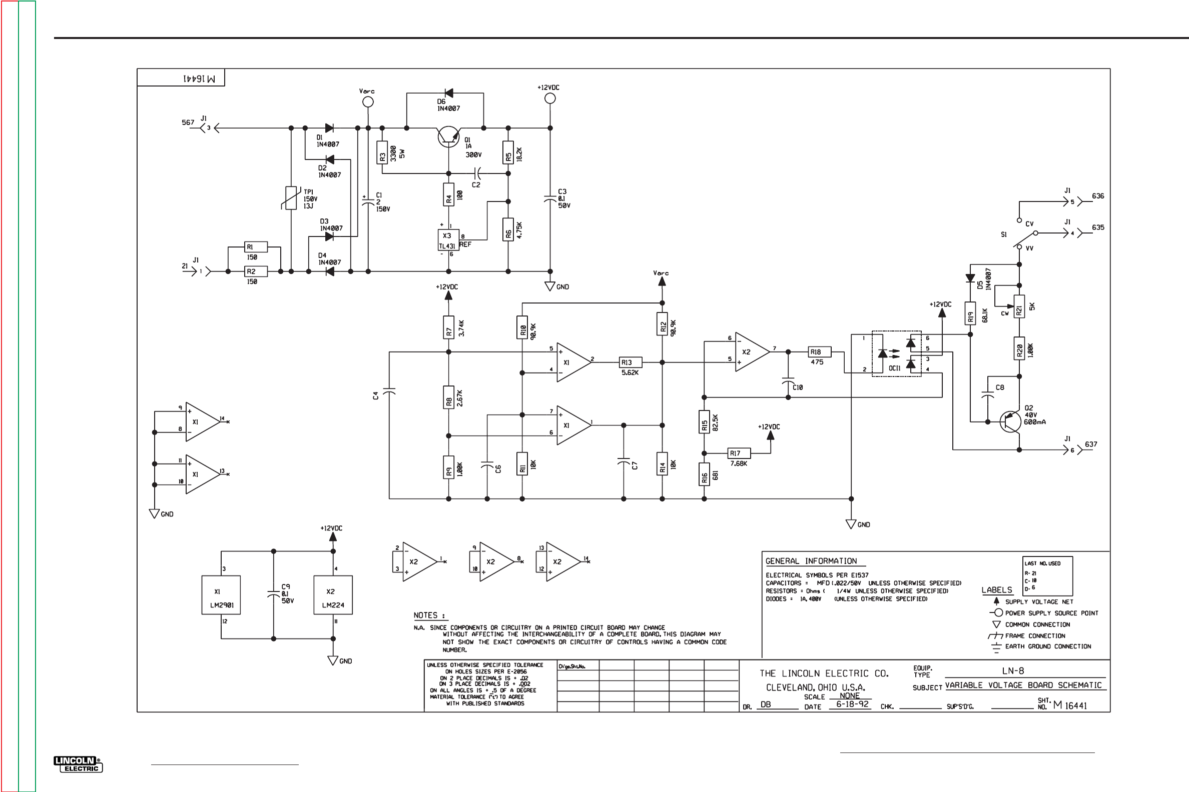
G-6
ELECTRICAL DIAGRAMS
LN-8
VARIABLE VOLTAGE BOARD (L5039) SCHEMATIC
12-3-92E
G-6
Return to Section TOC Return to Section TOC Return to Section TOC Return to Section TOC
Return to Master TOC Return to Master TOC Return to Master TOC Return to Master TOC
NOTE: Lincoln Electric assumes no responsibility for liablilities resulting from board level troubleshooting. PC Board repairs will invalidate your factory warranty. Individual Printed Circuit Board Components are not
available from Lincoln Electric. This information is provided for reference only. Lincoln Electric discourages board level troubleshooting and repair since it may compromise the quality of the design and may result
in danger to the Machine Operator or Technician. Improper PC board repairs could result in damage to the machine.
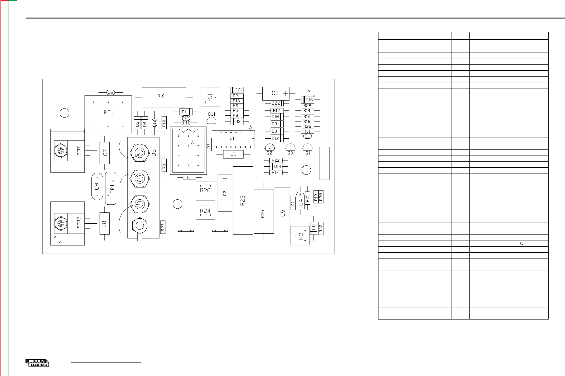
G-7
ELECTRICAL DIAGRAMS
LN-8
CONTROL BOARD (L5767) LAYOUT
LN-8 CONTROL L5767-1
D6D7
12345678
N
O
BAL CAL
FS
ITEM REQ’D. PART No.
IDENTIFICATION
C1
C2
C3
C4
C5
C6,C10,C11,C12,C13
C7,C8
C9
1
1
1
1
1
5
2
1
S13490-42
S13490-67
S13490-104
S13490-25
T11577-26
S16668-5
S13490-102
T11577-52
1.0/35
2/50
39uF/20V
4.7/35
.1/100
.022/50
.047/100
.0047 or .005/1400
D1,D2,D8,D9,D10,D11,D12,D13,D14
D3,D4
DZ1
DZ2
9
2
1
1
T12199-1
T12199-2
T12702-4
T12702-29
1N4004
1N4007
IN4747
1N4744A
L1
PT1
1
1
T12218-2
T12737-2
5.6mH
1:1:1
Q1,Q3
Q2
QU1
2
1
1
T12704-69
T12704-68
T12707-4
2N4403
2N4401
2N6027
R1
R2
R3,R14,R16,R22
R5,R6
R7
R8,R9
R10
R11
R12
R13
R15
R17
R18,R25
R19
R20,R29
R21
R23
R24,R26
R27
R28,R31
R30
1
1
4
2
1
2
1
1
1
1
1
1
2
1
2
1
1
2
1
2
1
S19400-6811
T10812-73
S19400-1002
S19400-4751
S19400-15R0
S19400-3322
S19400-7500
T10812-39
S19400-2672
S19400-3922
S19400-6812
S19400-2212
T14648-11
S19400-5622
S19400-1502
S19400-1501
T14764-2
T10812-68
S19400-1500
S19400-5110
S19400-5232
4700 5W
.25 7W
SCR1,SCR2 2 S15161-6 2N6397
TP1 1 T13640-11 45J
CAPACITORS = MFD/VOLTS
INDUCTANCE = HENRYS
RESISTORS = OHMS/ 1/4W UNLESS OTHERWISE SPECIFIED
2K 1/2W
50K 1/2W
1K 1/2W
1-24-97B
L5767-1
G-7
Return to Section TOC Return to Section TOC Return to Section TOC Return to Section TOC
Return to Master TOC Return to Master TOC Return to Master TOC Return to Master TOC
NOTE: Lincoln Electric assumes no responsibility for liablilities resulting from board level troubleshooting. PC Board repairs will invalidate your factory warranty. Individual Printed Circuit Board Components are not
available from Lincoln Electric. This information is provided for reference only. Lincoln Electric discourages board level troubleshooting and repair since it may compromise the quality of the design and may result
in danger to the Machine Operator or Technician. Improper PC board repairs could result in damage to the machine.
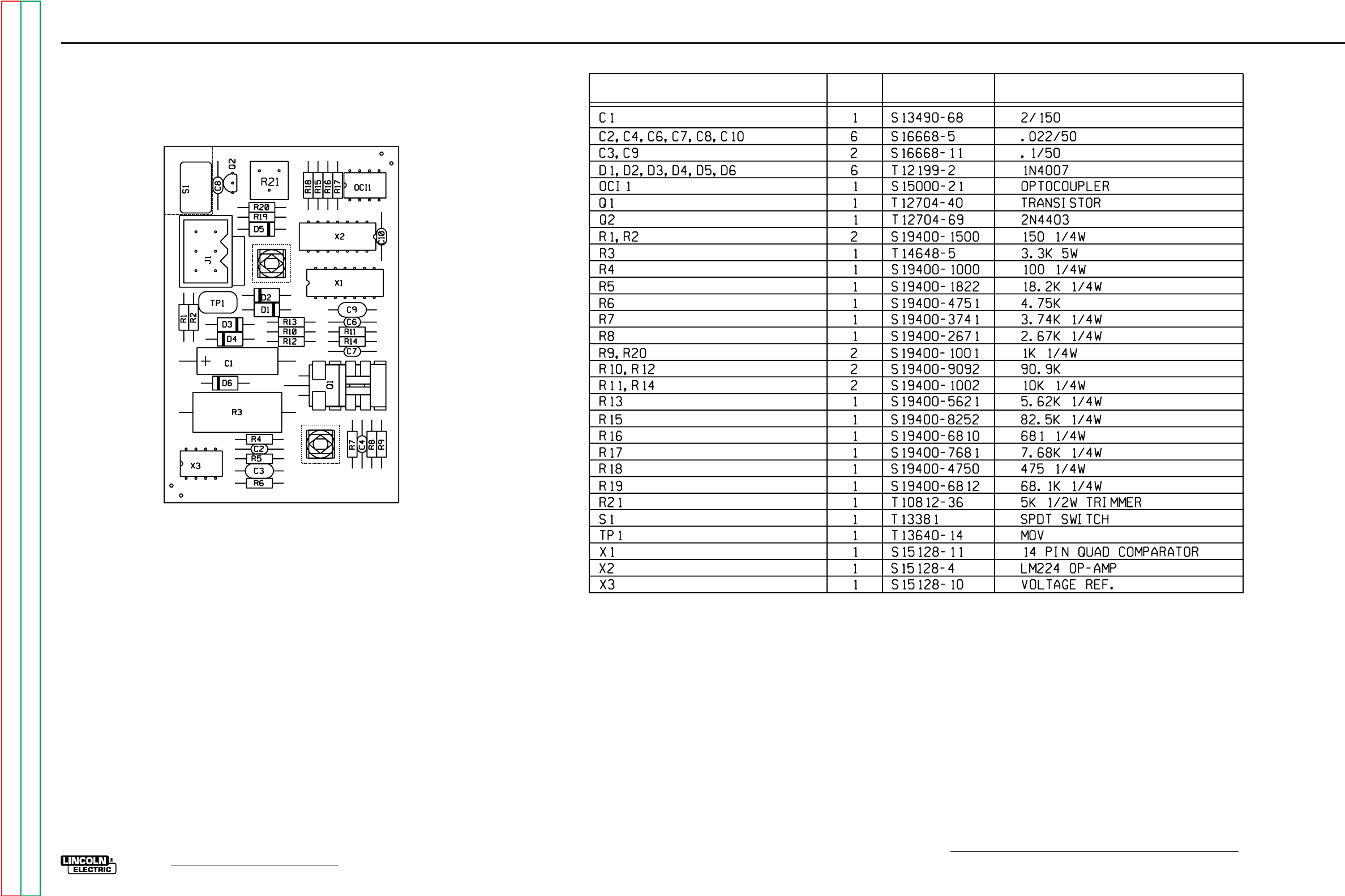
G-8
ELECTRICAL DIAGRAMS
LN-8
VARIABLE VOLTAGE BOARD (L5039) LAYOUT
IDENTIFICATION
PART NO.
REQ’D
ITEM
INDUCTANCE = HENRY
CAPACITORS = MFD VOLTS
L5039-1
LN-8 VARIABLE VOLTAGE VVCV
8-31-2001E
L5039-1
G-8
Return to Section TOC Return to Section TOC Return to Section TOC Return to Section TOC
Return to Master TOC Return to Master TOC Return to Master TOC Return to Master TOC
NOTE: Lincoln Electric assumes no responsibility for liablilities resulting from board level troubleshooting. PC Board repairs will invalidate your factory warranty. Individual Printed Circuit Board Components are not
available from Lincoln Electric. This information is provided for reference only. Lincoln Electric discourages board level troubleshooting and repair since it may compromise the quality of the design and may result
in danger to the Machine Operator or Technician. Improper PC board repairs could result in damage to the machine.

SVM ERROR REPORTING FORM
We need to know if there are errors in our manuals. We also value any suggestions as to
additional tests or procedures that would make this SVM a better tool for you.
If you discover new or different “Problems or Symptoms” that are not covered in the three col-
umn troubleshooting chart, please share this information with us. Please include the
machine’s code number and how the problem was resolved.
Thank You,
Technical Services Group
Lincoln Electric Co.
22801 ST. Clair Ave.
Cleveland, Ohio 44117-1199
FAX 216-481-2309
SVM Number ___________________________
Page Number if necessary__________________
Your Company__________________________
Your Name_____________________________
Please give detailed description below:
___________________________________________________________________________
___________________________________________________________________________
___________________________________________________________________________
___________________________________________________________________________
___________________________________________________________________________
___________________________________________________________________________
___________________________________________________________________________
___________________________________________________________________________
___________________________________________________________________________
___________________________________________________________________________
___________________________________________________________________________
___________________________________________________________________________
___________________________________________________________________________
SD287 01/99
Return to Section TOC Return to Section TOC Return to Section TOC Return to Section TOC
Return to Master TOC Return to Master TOC Return to Master TOC Return to Master TOC
