Lincoln Electric Ln 9 Semiautomatic Wire Feeder Im294 C Users Manual
LN-9 SEMIAUTOMATIC WIRE FEEDER IM294-C 7f5557cc-1676-4c62-8f11-a825d22c7427
IM294-C to the manual 7f5557cc-1676-4c62-8f11-a825d22c7427
2015-02-09
: Lincoln-Electric Lincoln-Electric-Ln-9-Semiautomatic-Wire-Feeder-Im294-C-Users-Manual-574293 lincoln-electric-ln-9-semiautomatic-wire-feeder-im294-c-users-manual-574293 lincoln-electric pdf
Open the PDF directly: View PDF ![]() .
.
Page Count: 148 [warning: Documents this large are best viewed by clicking the View PDF Link!]
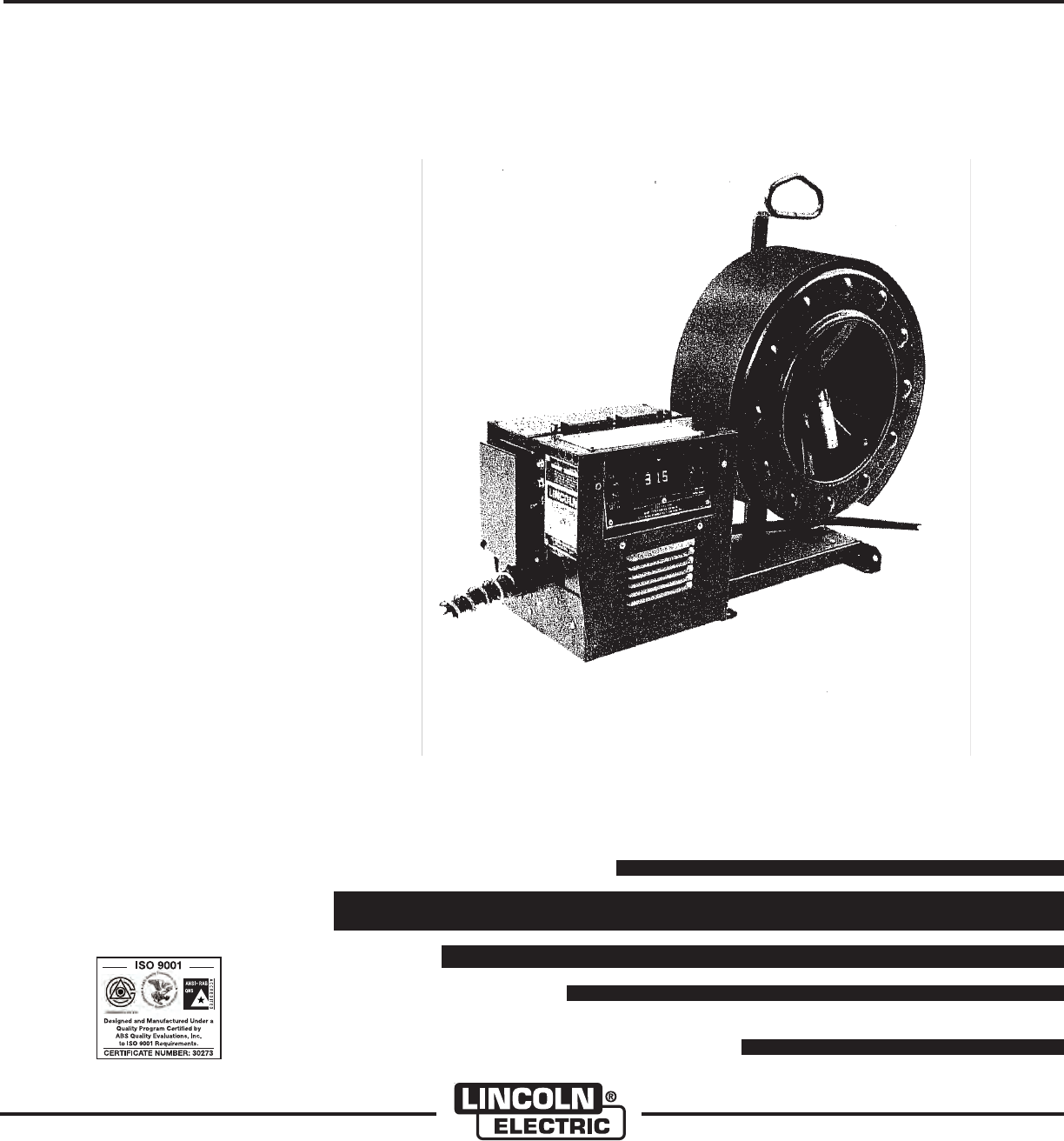
LN-9 SEMIAUTOMATIC WIRE FEEDER
OPERATOR’ S MANUAL
IM294-C
June, 2010
Safety Depends on You
Lincoln arc welding and cutting
equipment is designed and built
with safety in mind. However,
your overall safety can be
increased by proper installation
... and thoughtful operation on
your part. DO NOT INSTALL,
OPERATE OR REPAIR THIS
EQUIPMENT WITHOUT READ-
ING THIS MANUAL AND THE
SAFETY PRECAUTIONS CON-
TAINED THROUGHOUT. And,
most importantly, think before
you act and be careful.
August, 2006
s World's Leader in Welding and Cutting Products s
s Sales and Service through Subsidiaries and Distributors Worldwide s
Cleveland, Ohio 44117-1199 U.S.A. TEL: 216.481.8100 FAX: 216.486.1751 WEB SITE: www.lincolnelectric.com
Copyright © 2006 Lincoln Global Inc.
For Submerged Arc, Innershield® and Other Open
Arc Semiautomatic Arc Welding Processes
For Operation with Appropriate Lincoln
Power Sources
• Sales and Service through Subsidiaries and Distributors Worldwide •
Cleveland, Ohio 44117-1199 U.S.A. TEL: 216.481.8100 FAX: 216.486.1751 WEB SITE: www.lincolnelectric.com
• World's Leader in Welding and Cutting Products •
Copyright © Lincoln Global Inc.
RETURN TO MAIN MENU
FOR ENGINE
powered equipment.
1.a. Turn the engine off before troubleshooting and maintenance
work unless the maintenance work requires it to be running.
____________________________________________________
1.b. Operate engines in open, well-ventilated
areas or vent the engine exhaust fumes
outdoors.
____________________________________________________
1.c. Do not add the fuel near an open flame
welding arc or when the engine is running.
Stop the engine and allow it to cool before
refueling to prevent spilled fuel from vaporiz-
ing on contact with hot engine parts and
igniting. Do not spill fuel when filling tank. If
fuel is spilled, wipe it up and do not start
engine until fumes have been eliminated.
____________________________________________________
1.d. Keep all equipment safety guards, covers and devices in
position and in good repair.Keep hands, hair, clothing and
tools away from V-belts, gears, fans and all other moving
parts when starting, operating or repairing equipment.
____________________________________________________
1.e. In some cases it may be necessary to remove safety
guards to perform required maintenance. Remove
guards only when necessary and replace them when the
maintenance requiring their removal is complete.
Always use the greatest care when working near moving
parts.
___________________________________________________
1.f. Do not put your hands near the engine fan.
Do not attempt to override the governor or
idler by pushing on the throttle control rods
while the engine is running.
___________________________________________________
1.g. To prevent accidentally starting gasoline engines while
turning the engine or welding generator during maintenance
work, disconnect the spark plug wires, distributor cap or
magneto wire as appropriate.
i
SAFETY
i
ARC WELDING CAN BE HAZARDOUS. PROTECT YOURSELF AND OTHERS FROM POSSIBLE SERIOUS INJURY OR DEATH.
KEEP CHILDREN AWAY. PACEMAKER WEARERS SHOULD CONSULT WITH THEIR DOCTOR BEFORE OPERATING.
Read and understand the following safety highlights. For additional safety information, it is strongly recommended that you
purchase a copy of “Safety in Welding & Cutting - ANSI Standard Z49.1” from the American Welding Society, P.O. Box
351040, Miami, Florida 33135 or CSA Standard W117.2-1974. A Free copy of “Arc Welding Safety” booklet E205 is available
from the Lincoln Electric Company, 22801 St. Clair Avenue, Cleveland, Ohio 44117-1199.
BE SURE THAT ALL INSTALLATION, OPERATION, MAINTENANCE AND REPAIR PROCEDURES ARE
PERFORMED ONLY BY QUALIFIED INDIVIDUALS.
WARNING
ELECTRIC AND
MAGNETIC FIELDS
may be dangerous
2.a. Electric current flowing through any conductor causes
localized Electric and Magnetic Fields (EMF). Welding
current creates EMF fields around welding cables and
welding machines
2.b. EMF fields may interfere with some pacemakers, and
welders having a pacemaker should consult their physician
before welding.
2.c. Exposure to EMF fields in welding may have other health
effects which are now not known.
2.d. All welders should use the following procedures in order to
minimize exposure to EMF fields from the welding circuit:
2.d.1.
Route the electrode and work cables together - Secure
them with tape when possible.
2.d.2. Never coil the electrode lead around your body.
2.d.3. Do not place your body between the electrode and
work cables. If the electrode cable is on your right
side, the work cable should also be on your right side.
2.d.4. Connect the work cable to the workpiece as close as
possible to the area being welded.
2.d.5. Do not work next to welding power source.
1.h. To avoid scalding, do not remove the
radiator pressure cap when the engine is
hot.
CALIFORNIA PROPOSITION 65 WARNINGS
Diesel engine exhaust and some of its constituents
are known to the State of California to cause can-
cer, birth defects, and other reproductive harm.
The engine exhaust from this product contains
chemicals known to the State of California to cause
cancer, birth defects, or other reproductive harm.
The Above For Diesel Engines The Above For Gasoline Engines
ii
SAFETY
ii
ARC RAYS can burn.
4.a. Use a shield with the proper filter and cover
plates to protect your eyes from sparks and
the rays of the arc when welding or observing
open arc welding. Headshield and filter lens
should conform to ANSI Z87. I standards.
4.b. Use suitable clothing made from durable flame-resistant
material to protect your skin and that of your helpers from
the arc rays.
4.c. Protect other nearby personnel with suitable, non-flammable
screening and/or warn them not to watch the arc nor expose
themselves to the arc rays or to hot spatter or metal.
ELECTRIC SHOCK can
kill.
3.a. The electrode and work (or ground) circuits
are electrically “hot” when the welder is on.
Do not touch these “hot” parts with your bare
skin or wet clothing. Wear dry, hole-free
gloves to insulate hands.
3.b. Insulate yourself from work and ground using dry insulation.
Make certain the insulation is large enough to cover your full
area of physical contact with work and ground.
In addition to the normal safety precautions, if welding
must be performed under electrically hazardous
conditions (in damp locations or while wearing wet
clothing; on metal structures such as floors, gratings or
scaffolds; when in cramped positions such as sitting,
kneeling or lying, if there is a high risk of unavoidable or
accidental contact with the workpiece or ground) use
the following equipment:
• Semiautomatic DC Constant Voltage (Wire) Welder.
• DC Manual (Stick) Welder.
• AC Welder with Reduced Voltage Control.
3.c. In semiautomatic or automatic wire welding, the electrode,
electrode reel, welding head, nozzle or semiautomatic
welding gun are also electrically “hot”.
3.d. Always be sure the work cable makes a good electrical
connection with the metal being welded. The connection
should be as close as possible to the area being welded.
3.e. Ground the work or metal to be welded to a good electrical
(earth) ground.
3.f.
Maintain the electrode holder, work clamp, welding cable and
welding machine in good, safe operating condition. Replace
damaged insulation.
3.g. Never dip the electrode in water for cooling.
3.h. Never simultaneously touch electrically “hot” parts of
electrode holders connected to two welders because voltage
between the two can be the total of the open circuit voltage
of both welders.
3.i. When working above floor level, use a safety belt to protect
yourself from a fall should you get a shock.
3.j. Also see Items 6.c. and 8.
FUMES AND GASES
can be dangerous.
5.a. Welding may produce fumes and gases
hazardous to health. Avoid breathing these
fumes and gases. When welding, keep
your head out of the fume. Use enough
ventilation and/or exhaust at the arc to keep
fumes and gases away from the breathing zone. When
welding with electrodes which require special
ventilation such as stainless or hard facing (see
instructions on container or MSDS) or on lead or
cadmium plated steel and other metals or coatings
which produce highly toxic fumes, keep exposure as
low as possible and within applicable OSHA PEL and
ACGIH TLV limits using local exhaust or mechanical
ventilation. In confined spaces or in some circum-
stances, outdoors, a respirator may be required.
Additional precautions are also required when welding
on galvanized steel.
5. b. The operation of welding fume control equipment is affected
by various factors including proper use and positioning of
the equipment, maintenance of the equipment and the spe-
cific welding procedure and application involved. Worker
exposure level should be checked upon installation and
periodically thereafter to be certain it is within applicable
OSHA PEL and ACGIH TLV limits.
5.c.
Do not weld in locations near chlorinated hydrocarbon
vapors
coming from degreasing, cleaning or spraying operations.
The heat and rays of the arc can react with solvent vapors
to
form phosgene, a highly toxic gas, and other irritating prod-
ucts.
5.d. Shielding gases used for arc welding can displace air and
cause injury or death. Always use enough ventilation,
especially in confined areas, to insure breathing air is safe.
5.e. Read and understand the manufacturer’s instructions for this
equipment and the consumables to be used, including the
material safety data sheet (MSDS) and follow your
employer’s safety practices. MSDS forms are available from
your welding distributor or from the manufacturer.
5.f. Also see item 1.b.
iii
SAFETY
iii
FOR ELECTRICALLY
powered equipment.
8.a. Turn off input power using the disconnect
switch at the fuse box before working on
the equipment.
8.b. Install equipment in accordance with the U.S. National
Electrical Code, all local codes and the manufacturer’s
recommendations.
8.c. Ground the equipment in accordance with the U.S. National
Electrical Code and the manufacturer’s recommendations.
CYLINDER may explode
if damaged.
7.a. Use only compressed gas cylinders
containing the correct shielding gas for the
process used and properly operating
regulators designed for the gas and
pressure used. All hoses, fittings, etc. should be suitable for
the application and maintained in good condition.
7.b. Always keep cylinders in an upright position securely
chained to an undercarriage or fixed support.
7.c. Cylinders should be located:
• Away from areas where they may be struck or subjected to
physical damage.
• A safe distance from arc welding or cutting operations and
any other source of heat, sparks, or flame.
7.d. Never allow the electrode, electrode holder or any other
electrically “hot” parts to touch a cylinder.
7.e. Keep your head and face away from the cylinder valve outlet
when opening the cylinder valve.
7.f. Valve protection caps should always be in place and hand
tight except when the cylinder is in use or connected for
use.
7.g. Read and follow the instructions on compressed gas
cylinders, associated equipment, and CGA publication P-l,
“Precautions for Safe Handling of Compressed Gases in
Cylinders,” available from the Compressed Gas Association
1235 Jefferson Davis Highway, Arlington, VA 22202.
WELDING and CUTTING
SPARKS can
cause fire or explosion.
6.a.
Remove fire hazards from the welding area.
If this is not possible, cover them to prevent
the welding sparks from starting a fire.
Remember that welding sparks and hot
materials from welding can easily go through small cracks
and openings to adjacent areas. Avoid welding near
hydraulic lines. Have a fire extinguisher readily available.
6.b. Where compressed gases are to be used at the job site,
special precautions should be used to prevent hazardous
situations. Refer to “Safety in Welding and Cutting” (ANSI
Standard Z49.1) and the operating information for the
equipment being used.
6.c. When not welding, make certain no part of the electrode
circuit is touching the work or ground. Accidental contact
can cause overheating and create a fire hazard.
6.d. Do not heat, cut or weld tanks, drums or containers until the
proper steps have been taken to insure that such procedures
will not cause flammable or toxic vapors from substances
inside. They can cause an explosion even
though
they have
been “cleaned”. For information, purchase “Recommended
Safe Practices for the
Preparation
for Welding and Cutting of
Containers and Piping That Have Held Hazardous
Substances”, AWS F4.1 from the American Welding Society
(see address above).
6.e. Vent hollow castings or containers before heating, cutting or
welding. They may explode.
6.f.
Sparks and spatter are thrown from the welding arc. Wear oil
free protective garments such as leather gloves, heavy shirt,
cuffless trousers, high shoes and a cap over your hair. Wear
ear plugs when welding out of position or in confined places.
Always wear safety glasses with side shields when in a
welding area.
6.g. Connect the work cable to the work as close to the welding
area as practical. Work cables connected to the building
framework or other locations away from the welding area
increase the possibility of the welding current passing
through lifting chains, crane cables or other alternate cir-
cuits. This can create fire hazards or overheat lifting chains
or cables until they fail.
6.h. Also see item 1.c.
6.I. Read and follow NFPA 51B “ Standard for Fire Prevention
During Welding, Cutting and Other Hot Work”, available
from NFPA, 1 Batterymarch Park, PO box 9101, Quincy, Ma
022690-9101.
6.j. Do not use a welding power source for pipe thawing.
Refer to http://www.lincolnelectric.com/safety for additional safety information.

PRÉCAUTIONS DE SÛRETÉ
Pour votre propre protection lire et observer toutes les instructions
et les précautions de sûreté specifiques qui parraissent dans ce
manuel aussi bien que les précautions de sûreté générales suiv-
antes:
Sûreté Pour Soudage A L’Arc
1. Protegez-vous contre la secousse électrique:
a. Les circuits à l’électrode et à la piéce sont sous tension
quand la machine à souder est en marche. Eviter toujours
tout contact entre les parties sous tension et la peau nue
ou les vétements mouillés. Porter des gants secs et sans
trous pour isoler les mains.
b. Faire trés attention de bien s’isoler de la masse quand on
soude dans des endroits humides, ou sur un plancher
metallique ou des grilles metalliques, principalement dans
les positions assis ou couché pour lesquelles une grande
partie du corps peut être en contact avec la masse.
c. Maintenir le porte-électrode, la pince de masse, le câble
de soudage et la machine à souder en bon et sûr état
defonctionnement.
d.Ne jamais plonger le porte-électrode dans l’eau pour le
refroidir.
e. Ne jamais toucher simultanément les parties sous tension
des porte-électrodes connectés à deux machines à souder
parce que la tension entre les deux pinces peut être le
total de la tension à vide des deux machines.
f. Si on utilise la machine à souder comme une source de
courant pour soudage semi-automatique, ces precautions
pour le porte-électrode s’applicuent aussi au pistolet de
soudage.
2. Dans le cas de travail au dessus du niveau du sol, se protéger
contre les chutes dans le cas ou on recoit un choc. Ne jamais
enrouler le câble-électrode autour de n’importe quelle partie
du corps.
3. Un coup d’arc peut être plus sévère qu’un coup de soliel,
donc:
a. Utiliser un bon masque avec un verre filtrant approprié
ainsi qu’un verre blanc afin de se protéger les yeux du ray-
onnement de l’arc et des projections quand on soude ou
quand on regarde l’arc.
b. Porter des vêtements convenables afin de protéger la
peau de soudeur et des aides contre le rayonnement de
l‘arc.
c. Protéger l’autre personnel travaillant à proximité au
soudage à l’aide d’écrans appropriés et non-inflammables.
4. Des gouttes de laitier en fusion sont émises de l’arc de
soudage. Se protéger avec des vêtements de protection libres
de l’huile, tels que les gants en cuir, chemise épaisse, pan-
talons sans revers, et chaussures montantes.
5. Toujours porter des lunettes de sécurité dans la zone de
soudage. Utiliser des lunettes avec écrans lateraux dans les
zones où l’on pique le laitier.
6. Eloigner les matériaux inflammables ou les recouvrir afin de
prévenir tout risque d’incendie dû aux étincelles.
7. Quand on ne soude pas, poser la pince à une endroit isolé de
la masse. Un court-circuit accidental peut provoquer un
échauffement et un risque d’incendie.
8. S’assurer que la masse est connectée le plus prés possible
de la zone de travail qu’il est pratique de le faire. Si on place
la masse sur la charpente de la construction ou d’autres
endroits éloignés de la zone de travail, on augmente le risque
de voir passer le courant de soudage par les chaines de lev-
age, câbles de grue, ou autres circuits. Cela peut provoquer
des risques d’incendie ou d’echauffement des chaines et des
câbles jusqu’à ce qu’ils se rompent.
9. Assurer une ventilation suffisante dans la zone de soudage.
Ceci est particuliérement important pour le soudage de tôles
galvanisées plombées, ou cadmiées ou tout autre métal qui
produit des fumeés toxiques.
10. Ne pas souder en présence de vapeurs de chlore provenant
d’opérations de dégraissage, nettoyage ou pistolage. La
chaleur ou les rayons de l’arc peuvent réagir avec les vapeurs
du solvant pour produire du phosgéne (gas fortement toxique)
ou autres produits irritants.
11. Pour obtenir de plus amples renseignements sur la sûreté,
voir le code “Code for safety in welding and cutting” CSA
Standard W 117.2-1974.
PRÉCAUTIONS DE SÛRETÉ POUR
LES MACHINES À SOUDER À
TRANSFORMATEUR ET À
REDRESSEUR
1. Relier à la terre le chassis du poste conformement au code de
l’électricité et aux recommendations du fabricant. Le dispositif
de montage ou la piece à souder doit être branché à une
bonne mise à la terre.
2. Autant que possible, I’installation et l’entretien du poste seront
effectués par un électricien qualifié.
3. Avant de faires des travaux à l’interieur de poste, la debranch-
er à l’interrupteur à la boite de fusibles.
4. Garder tous les couvercles et dispositifs de sûreté à leur
place.
iv
SAFETY
iv
vv
Thank You for selecting a QUALITY product by Lincoln Electric. We want you
to take pride in operating this Lincoln Electric Company product
••• as much pride as we have in bringing this product to you!
Read this Operators Manual completely before attempting to use this equipment. Save this manual and keep it
handy for quick reference. Pay particular attention to the safety instructions we have provided for your protection.
The level of seriousness to be applied to each is explained below:
WARNING
This statement appears where the information must be followed exactly to avoid serious personal injury or loss of life.
This statement appears where the information must be followed to avoid minor personal injury or damage to this equipment.
CAUTION
Please Examine Carton and Equipment For Damage Immediately
When this equipment is shipped, title passes to the purchaser upon receipt by the carrier. Consequently, Claims
for material damaged in shipment must be made by the purchaser against the transportation company at the
time the shipment is received.
Please record your equipment identification information below for future reference. This information can be
found on your machine nameplate.
Product _________________________________________________________________________________
Model Number ___________________________________________________________________________
Code Number or Date Code_________________________________________________________________
Serial Number____________________________________________________________________________
Date Purchased___________________________________________________________________________
Where Purchased_________________________________________________________________________
Whenever you request replacement parts or information on this equipment, always supply the information you
have recorded above. The code number is especially important when identifying the correct replacement parts.
On-Line Product Registration
- Register your machine with Lincoln Electric either via fax or over the Internet.
• For faxing: Complete the form on the back of the warranty statement included in the literature packet
accompanying this machine and fax the form per the instructions printed on it.
• For On-Line Registration: Go to our
WEB SITE at www.lincolnelectric.com. Choose “Quick Links” and then
“Product Registration”. Please complete the form and submit your registration.
CUSTOMER ASSISTANCE POLICY
The business of The Lincoln Electric Company is manufacturing and selling high quality welding equipment, consumables, and cutting equip-
ment. Our challenge is to meet the needs of our customers and to exceed their expectations. On occasion, purchasers may ask Lincoln
Electric for advice or information about their use of our products. We respond to our customers based on the best information in our posses-
sion at that time. Lincoln Electric is not in a position to warrant or guarantee such advice, and assumes no liability, with respect to such infor-
mation or advice. We expressly disclaim any warranty of any kind, including any warranty of fitness for any customer’s particular purpose,
with respect to such information or advice. As a matter of practical consideration, we also cannot assume any responsibility for updating or
correcting any such information or advice once it has been given, nor does the provision of information or advice create, expand or alter any
warranty with respect to the sale of our products.
Lincoln Electric is a responsive manufacturer, but the selection and use of specific products sold by Lincoln Electric is solely within the control
of, and remains the sole responsibility of the customer. Many variables beyond the control of Lincoln Electric affect the results obtained in
applying these types of fabrication methods and service requirements.
Subject to Change – This information is accurate to the best of our knowledge at the time of printing. Please refer to www.lincolnelectric.com
for any updated information.

Input Power (115VAC, 4.5A) is supplied by the power souce.
Connect to appropriate Lincoln power source as follows:

Sec. N2.3.2 (continue)
9. Actual Value Push Button:
This button us used to allow the meter to be changed
from a preset readout to a reading of actual arc voltage
or wire feed speed.
10. Direct Work Lead Jack (below code 8200):
This jack permits connection of the direct work clip lead
to the LN-9 to more accurately monitor arc voltage. See
Sec. N4.4.4 for direct work lead connection of later LN-9
models.
11. Duty Cycle:
The amount of welding performed in a 10 minute period,
expressed as a percentage.


01-01-2007
ITEM DESCRIPTION PART NO. QTY. 123456789
Work Jack T14280 1
Input Amphenol S12021-12 1
Output Amphenol S12021-3 1
Heat Sink (LN9 & LN9H) (Part of Motor) M13579 1
Insulator (LN9 & LN9H) (Part of Motor) S16267 1
Drive Motor Cover (LN9F & LN9FH) (Part of Motor)
S16718 1
Grommet (LN9F & LN9FH) (Part of Motor) S10255-12 1
Hose Nipple T15008 1
Inert Arc Nut T15007-1 1
Handle (Optional) S13863 1
Burn Back Jumper Plug T13498-3 1
Collar Assembly T12341 1
Button Head Socket Screw T11551-6 1
Key M8776-31 1
Sems Screw T10082-26 1
Key M8776-82 1
Sems Screw T10082-4 1
Plug Button T10397-4 1
Wiring Harness (Code 8421, 8423, 8670, 8671,
8990, 8991) L6323-7 1
Wiring Harness (Code 9089, 9090, 9131, 9756, 9959) L6323-8 1
Wiring Harness (Code 9159, 9844, 9961, 10248,
10249,10322,10350, 10351) L6323-9 1
Wiring Harness (Code 10355, 10356) L6323-10 1
Wiring Harness (Code 9134, 9842, 9958, 10316,
10327) L7202-1 1
Wiring Harness (Code 9135, 9160, 9843, 9960,
10326) L7271 1
Wiring Harness (Code 10353, 10354) L7271-1 1
P-127-B.2P-127-B.2
# Indicates a Change This Printing
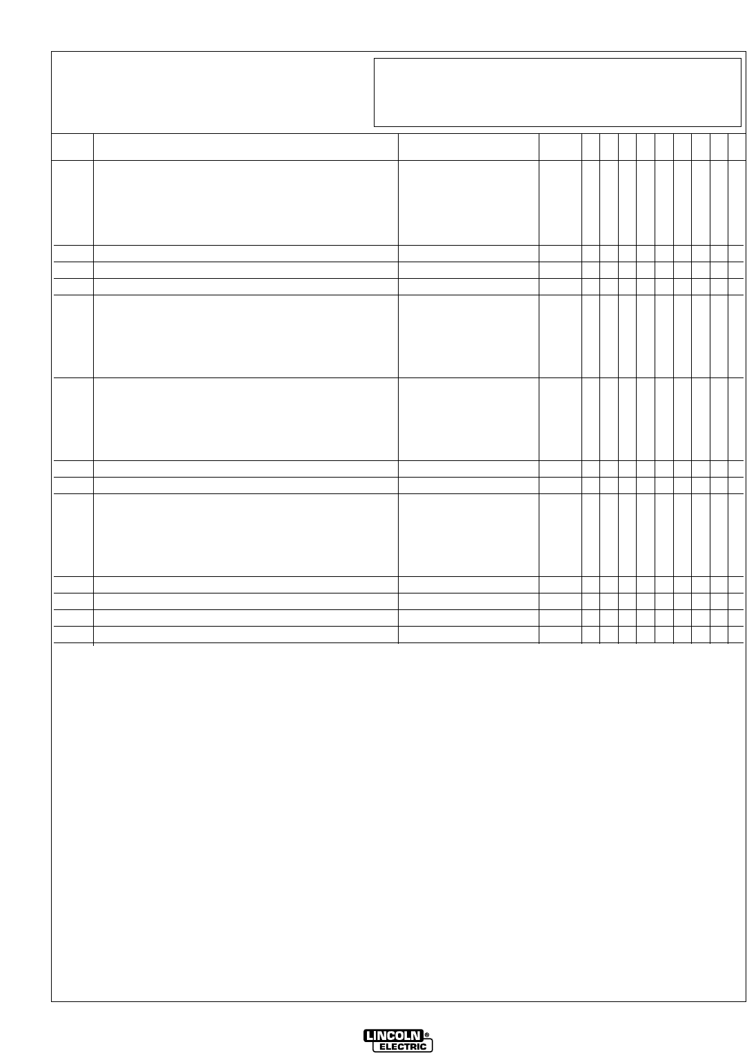
MISCELLANEOUS ITEMS
(These Items Are Not Illustrated)
LN9 AND LN9 GMA

NOTES
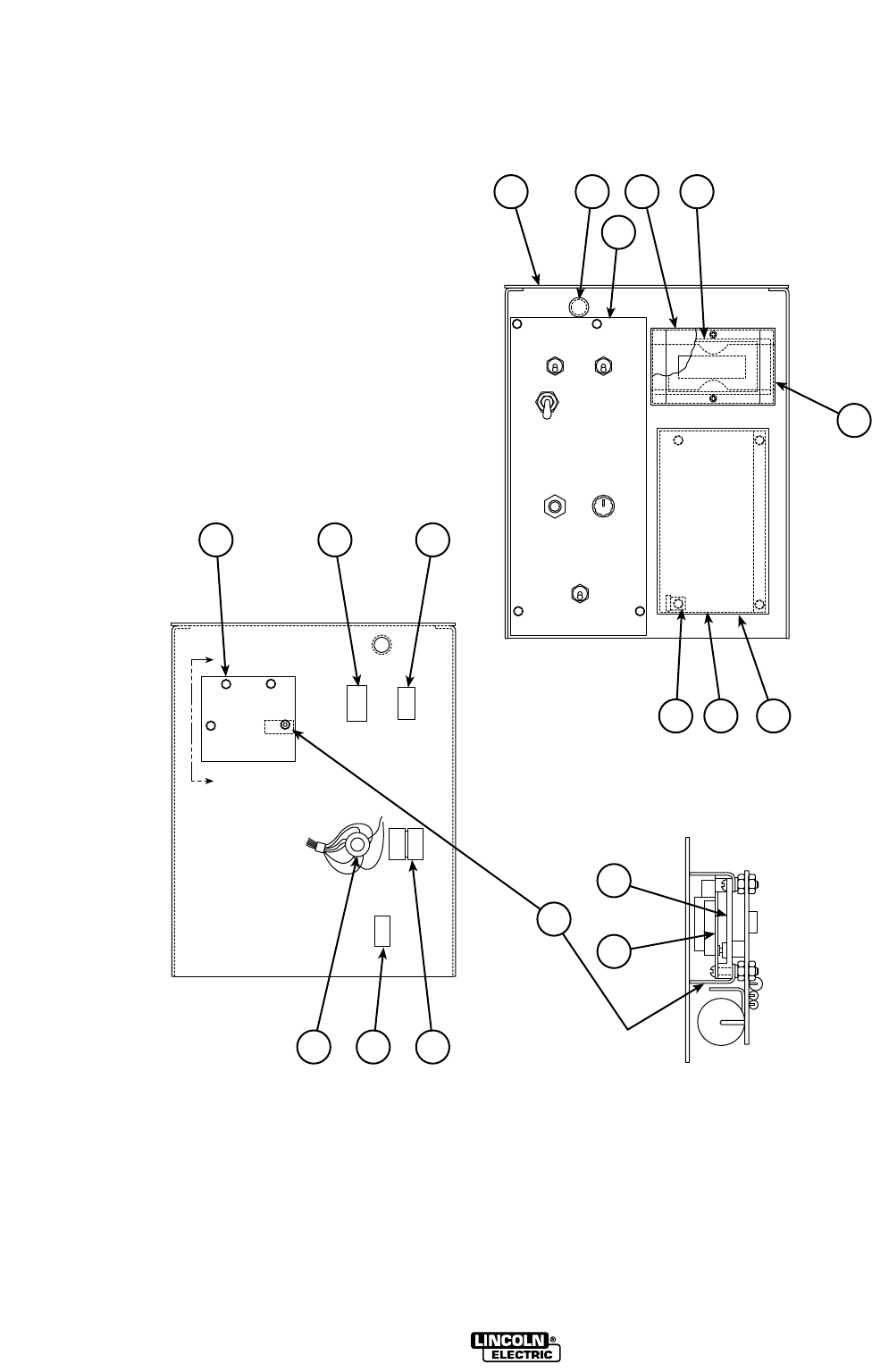
LN9 AND LN9 GMA
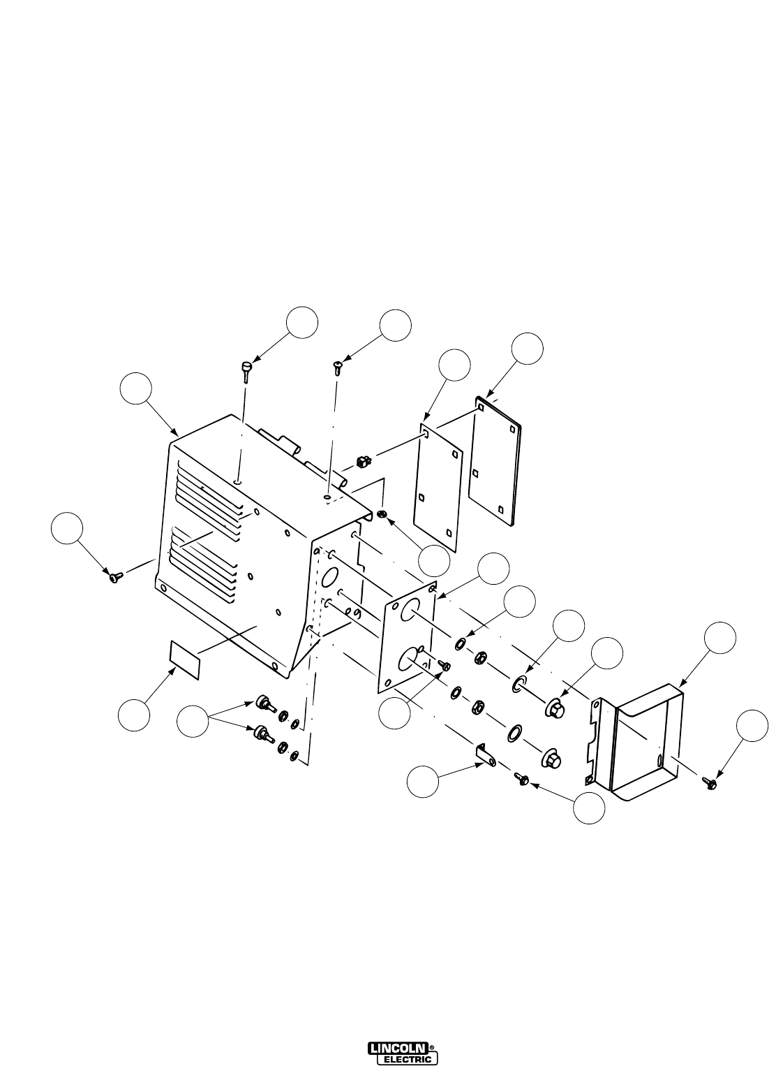
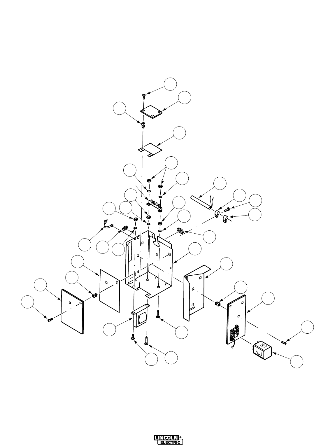
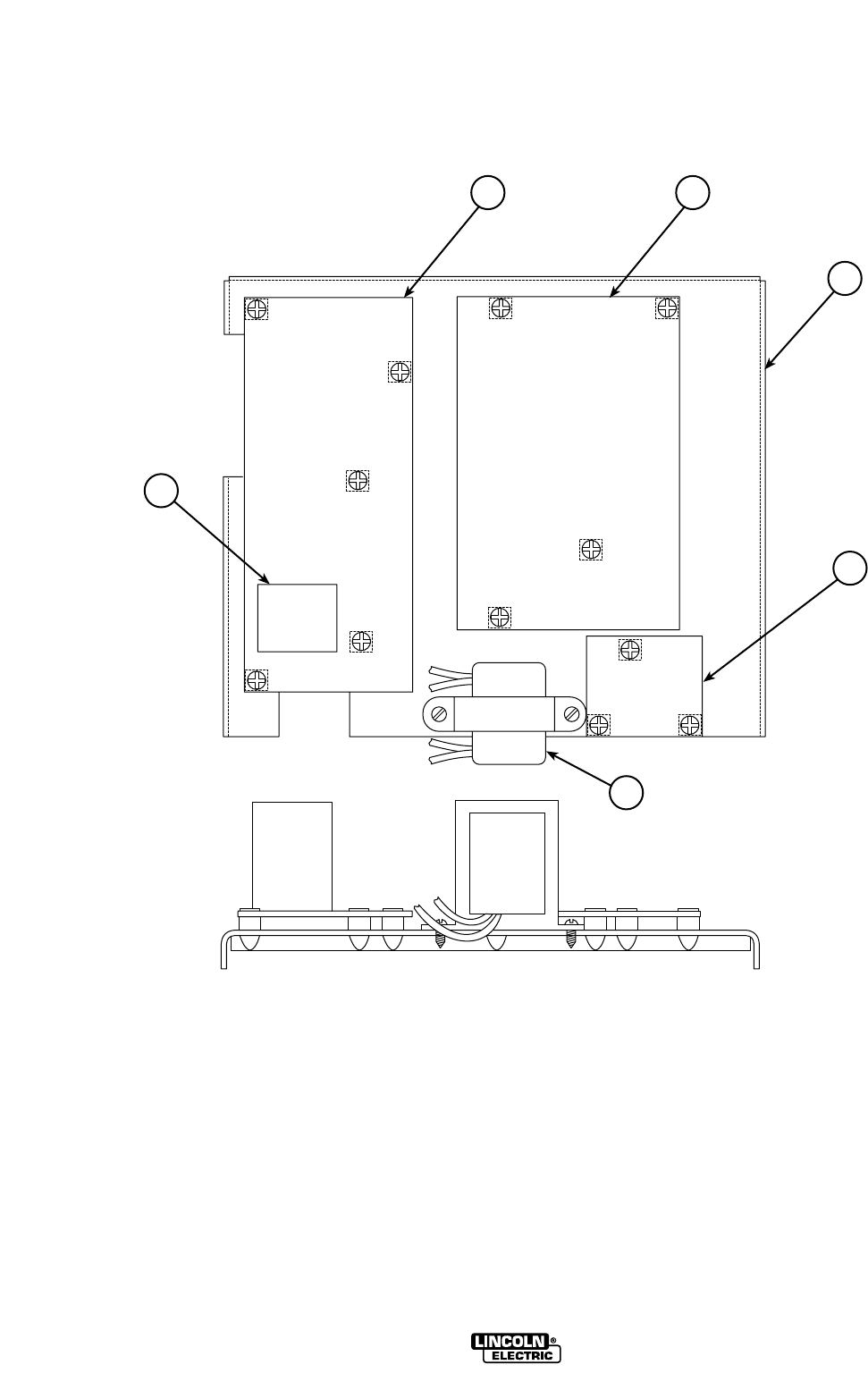
CONTROL BOX
LN9 & LN9 GMA
(2-Roll & 4-Roll)
P-127-CP-127-C
Part Numbers Part Numbers Part Numbers Part Numbers
1-28-2002
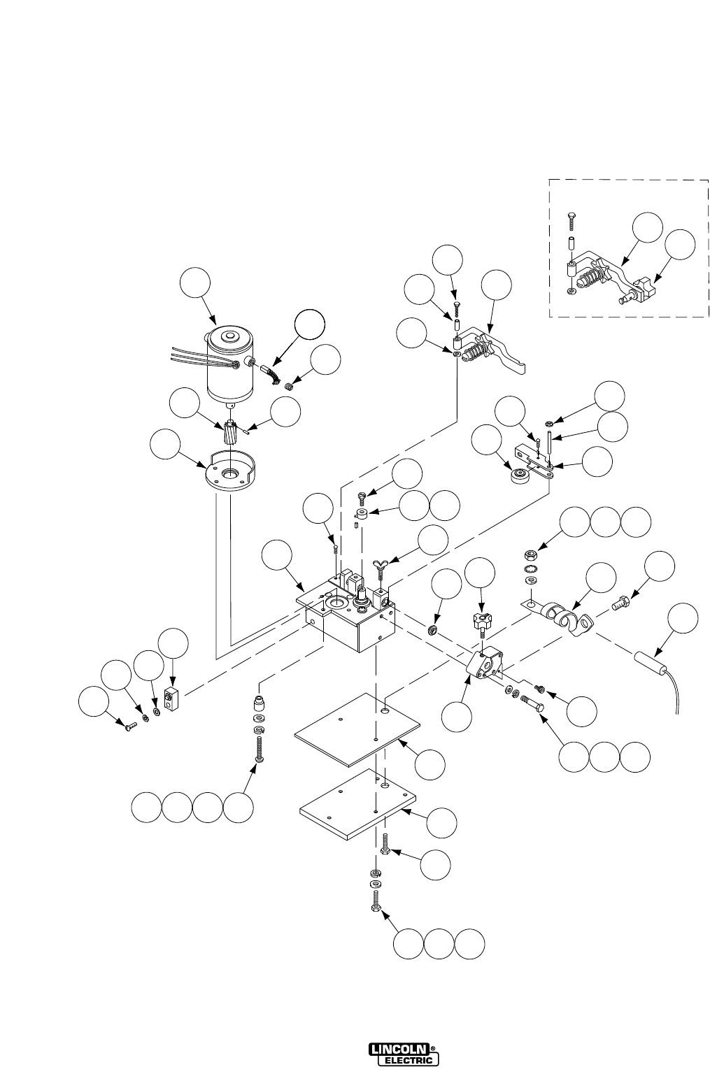
LN9 AND LN9 GMA
1
45A
6A
6B
5D 10
9C
9B
8
7
12
12
11
13
9A
2
3
LN9 AND LN9 GMA
ITEM DESCRIPTION PART NO. QTY. 123456789
1 Cover Assembly (Below Code 8200) M12216-1 1 X •
1 Cover Assembly ( Code 8200 to Code 9000) M12216-2 1 X •
1 Cover Assembly ( Code 9000 & Above) M14851-3 1 X •
1 Cover Assembly M14851-5 1 • X
2 Self Tapping Screw S8025-14 4 X X
3 Warning Decal T13470 1 X X
4 Door Bumper T14882 1 X X
5A #8-32x.50 Round Head Screw CF000033 1 X X
5B Plain Washer (Not Shown) S9262-3 1 X X
5C Lock Washer (Not Shown) T4291-A 1 X X
5D #8-32 Hex Nut CF000042 1 X X
5E Lead Clamp (Not Shown) T12563-7 1 X X
6A Voltage P.C. Board (Code 7949 Only) L6041 1 X •
6A Voltage P.C. Board (Code 7949-A to 9000) L6084 1 X •
6A Voltage P.C. Board (Code 9000 to 9100) L6084-2 1 X •
6A Voltage P.C. Board (Above Code 9100) L6084-[ ] 1 X X
6B P.C. Board Insulation S16364 1 X X
7 Security Panel S16275 1 X X
8 Knob T10491 2 X X
9
Potentiometer & Plug Assembly, includes: (Not Shown)
S14165-173 1 X X
9A Potentiometer S16296-1 2 X X
9B Felt Washer T14034 2 X X
9C Plain Washer S9262-76 2 X X
9D Insulating Tube T7028-241 2 X X
10 Dial Plate S16277 1 X X
11 Lock Tab T10045-40 1 X X
12 Self Tapping Screw S8025-70 4 X X
13 Self Tapping Screw S8025-60 1 X X
10-04-2005
Use Column 1 for LN9, LN9H, LN9 GMA (2 Roll Drive)
Use Column 2 for LN9, and LN9 GMA (4 Roll Drive)
Use only the parts marked “X” in the column under the
heading number called for in the model index page.
P-127-C.1P-127-C.1
# Indicates a Change This Printing
Sub Assembly Illustration Sub Assembly Illustration Sub Assembly Illustration Sub Assembly Illustration
#
Note: When ordering new printed circuit boards indicate the dash number [ ] of the “Old” board
that is to be replaced. This will aid Lincoln in supplying the correct and latest board along
with any necessary jumpers or adapters. The dash number brackets [ ] have purposely
been left blank so as to eliminate errors, confusion and updates.
P-127-DP-127-D
Part Numbers Part Numbers Part Numbers Part Numbers
1-96
1
2
3
4A
4B
5
8C
7
6
10
9
8A 8B
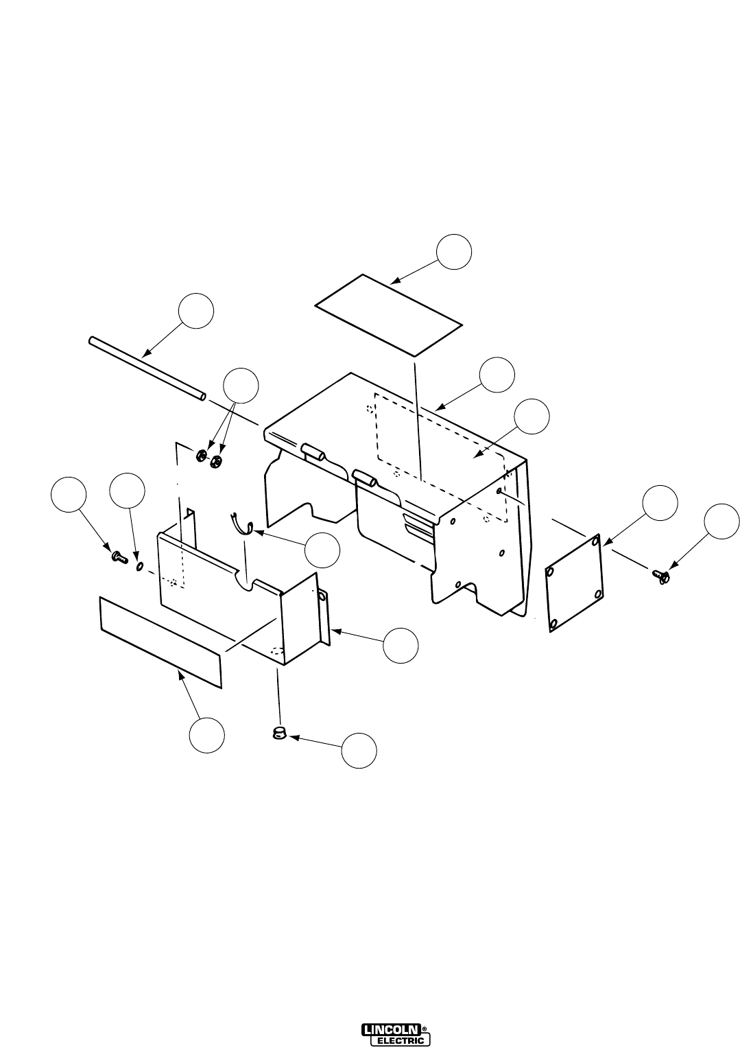
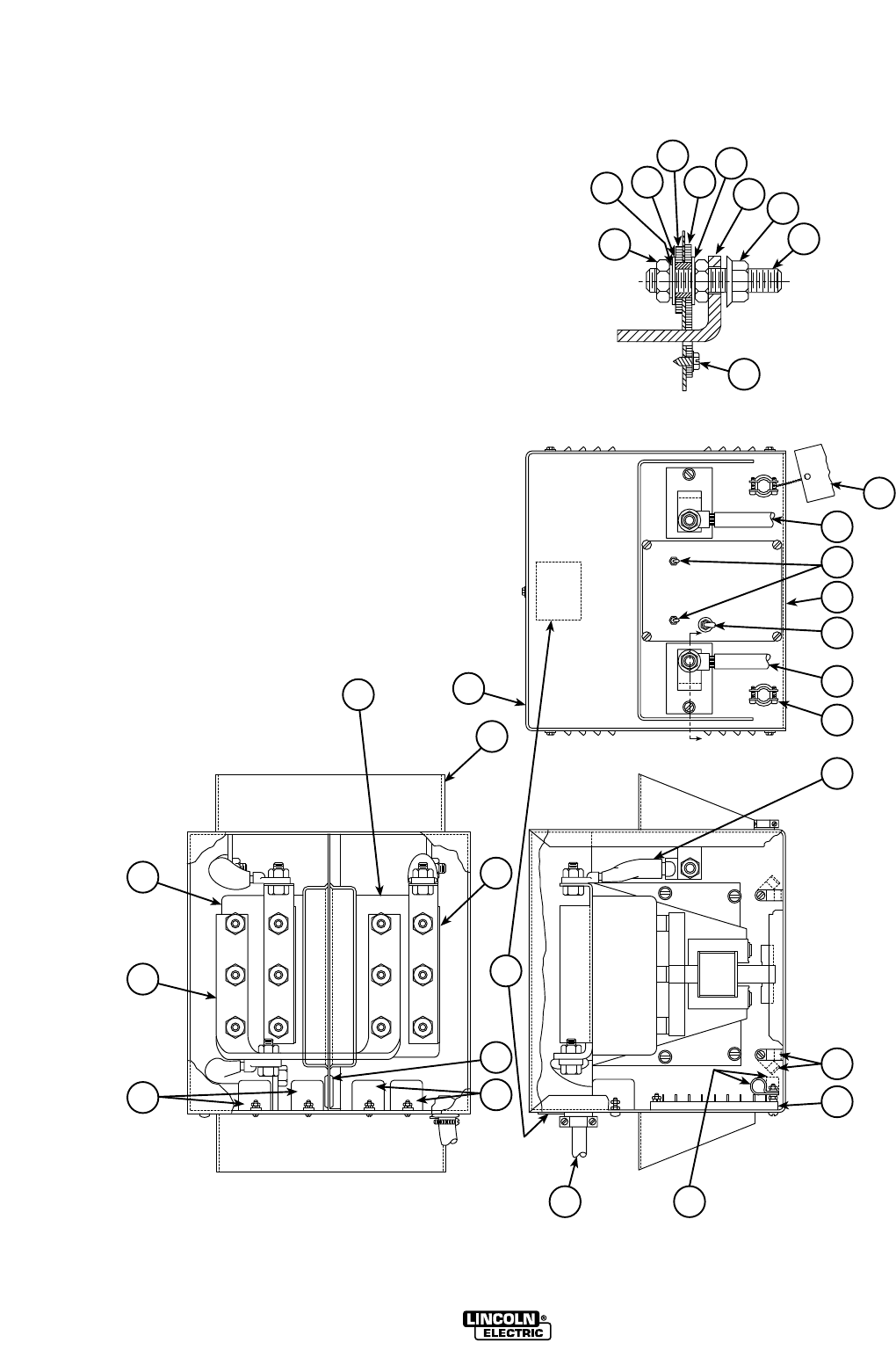
HINGED DOOR ASSEMBLY
LN9 & LN9 GMA
(2-Roll & 4-Roll)
LN9 AND LN9 GMA

ITEM DESCRIPTION PART NO. QTY. 123456789
Use Column 1 for LN9, LN9H, LN9 GMA (2 Roll Drive)
Use Column 2 for LN9, and LN9 GMA (4 Roll Drive)
LN9 AND LN9 GMA
1 Warning Decal M16196 1 X X
2 Door Assembly (Below Code 9000) M11490-1 1 X •
2 Door Assembly (Above Code 9000) M14850-2
ø
1X•
2 Door Assembly (Red) M16806 1 • X
3 Meter Panel Assembly See P127-G 1 X X
4A Nameplate (LN9 Only) S16279 1 X •
4A Nameplate (LN9H Only) S16623 1 X •
4A Nameplate (LN9 GMA) S18003 1 X •
4A Nameplate (LN9, 4 Roll Drive) S20424-1 1 • X
4A Nameplate (LN9 GMA, 4-Roll Drive) S20424-2 1 • X
4B Self Tapping Screw S8025-70 4 X X
5 Hinge Pin M8809-53 1 X X
6
Meter Panel Enclosure (Except LN9, GMA 2 & 4 Roll
S16502 1 X •
Drive & LN9, 4 Roll Drive)
6
Meter Panel Enclosure (LN9 GMA 2 & 4 Roll Drive)
S18005 1 X •
6 Meter Panel Enclosure (LN9, 4 Roll Drive) S16502-1 1 • X
6
Meter Panel Enclosure LN9 GMA, 4 Roll Drive)
S18005-1 1 X X
7 Grommet Strip T12823-14 1 X X
8A Thread Cutting Screw S9225-36 1 X X
8B Lock Washer T9695-1 1 X X
8C Hex Nut #10-24 2 X X
9 Drive Roll Decal S17973 1 X •
9 Drive Roll Decal (Below Code 10351) S20101 1 • X
9 Drive Roll Decal (Above Code 10351) S22739-2 1 • X
10 Plug Button T13597-2 4 X X
01-01-2007
Sub Assembly Illustration Sub Assembly Illustration Sub Assembly Illustration Sub Assembly Illustration
P-127-D.1P-127-D.1
# Indicates a Change This Printing
øThis part is obsolete and no longer available.
P-127-EP-127-E
Part Numbers Part Numbers Part Numbers Part Numbers
1-28-2002
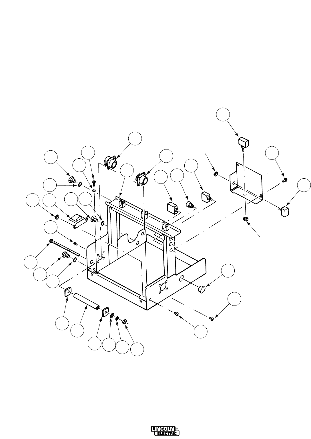
BASE PLATFORM
LN9 & LN9 GMA
(2-Roll & 4-Roll)
LN9 AND LN9 GMA
1
23
4
5
6
Part of 13B
13B
12
13A
Part of 13A
15
8
7B
9C
9A
9C 9D 9E 9F
16A
16B
8
9B
7C 7A 16A 16B
11B
11A
10B
10A
01-01-2007
LN9 AND LN9 GMA
ITEM DESCRIPTION PART NO. QTY. 123456789
1 Base Assembly (Below Code 8000) L5778-4 1 X •
1 Base Assembly (Code 8178 thru 8180) L5778-5 1 X •
1 Base Assembly (Code 8420 and up) and L5778-7 1 X •
(LN-9 & LN-9H Only)
1 Base Assembly (LN9 GMA Only) L7269 1 X •
1 Base Assembly (LN9, 4 Roll Only) L8815 1 • X
2 Circuit Breaker (LN9) (2 & 4 Roll Drive) T12287-10 1 X X
2
Circuit Breaker (LN9H, LN9 GMA) (2 & 4 Roll Drive)
T12287-8 1 X X
(Above Code 8000)
3 Push Button Switch GLP T14200 1 X X
4 Hot-Cold Interlock Switch (Above Code 8000) T10800-12 1 X X
5 Input Connector S12021-12 1 X X
6 Output Connector Assembly S12021-3 1 X X
7A Transformer Assembly S14651-5 1 X X
7B Sems Screw T10082-27 2 X X
7C #8-32 Hex Nut CF000042 2 X X
8 Self Tapping Screw S8025-73 8 X X
9A Resistor S10404-75 1 X X
9B #10-24x5.00 Round Head Screw CF000045 1 X X
9C Insulating Washer T4479-A 2 X X
9D Plain Washer S9262-27 1 X X
9E Lock Washer E106A-1 1 X X
9F #10-24 Hex Nut CF000010 1 X X
10A Thread Forming Screw S9225 4 X X
10B Lock Washer T9695-1 1 X X
11A 3/8-16x.875 Hex Head Cap Screw CF000070 1 X X
11B Lock Washer E106A-16 1 X X
11C Plain Washer S9262-120 2 X X
12 Self Tapping Screw S8025-4 2 X X
13
Switch Box Assembly, includes: (Below Code 8000)
S16270
ø
1X•
13
Switch Box Assembly, includes: (Above Code 8000)
S16270-1 1 X X
(Except LN9 GMA 2 & 4 Roll)
13
Switch Box Assembly, includes: (LN9 GMA 2 & 4
S16270-2 1 X X
Roll Drive)
13A Polarity Switch T13111 1 X X
13B Direction Switch (Above Code 8000) T14535 1 X X
(Except LN9 GMA)
13B Direction Switch (LN9 GMA) T10800-7 1 X X
13C Trigger Interlock Switch (Below Code 8000) T10800-4 1 X X
(Not Shown)
14 Switch Box (Not Shown) M13576 1 X X
15 Plug Button (LN9, 4 Roll Only) T10397-4 2 • X
16A 3/8-16x.625 Hex Head Cap Screw CF000018 2 X X
16B Lock Washer E106A-16 2 X X
* Resistance Coil (Below Code 9100) T14104 1 X •
Use Column one for (2 Roll).
Use Column two for (4 Roll)
P-127-E.1P-127-E.1
# Indicates a Change This Printing
Sub Assembly Illustration Sub Assembly Illustration Sub Assembly Illustration Sub Assembly Illustration
øThis part is obsolete and no longer available.
P-127-FP-127-F
Part Numbers Part Numbers Part Numbers Part Numbers
1-96
1A
1B
1C
1D
8C
8B
8B
8B
8C
8C
8B
Not Sold
911 10B
13
10C
2
34
3
6
7B
8C
7A
7D
15
8A
12
5B
5C
5A
5D
10A 8A
CONTROL PANEL INSTRUMENT ASSEMBLY
LN9 & LN9 GMA
(2-Roll & 4-Roll)
LN9 AND LN9 GMA
LN9 AND LN9 GMA 10-20-2006
ITEM DESCRIPTION PART NO. QTY. 123456789
1A Self Tapping Screw S8025-14 3 X
1B Trigger P.C. Board M13861-3 1 X
1B Trigger P.C. Board (Above Code 8000)(GMA) L9928-[ ] 1 X
1C Plastic Expansion Nut S14020-1 3 X
1D P.C. Board Insulation (Below Code 8000) T14274 1 X
1D P.C. Board Insulation (Above Code 8000) S16609 1 X
2 Reed Switch Assembly S12334-29 1 X
3 Lead Clamp T12563-7 2 X
4 #8-32x.50 Br RHS CF000102 2 X
5A Control P.C. Board (LN9 & 9H Only) L6019 1 X
5A
Control P.C. Board (LN9 GMA Only (Below Code 10352)
L7253-[ ] 1 X
5A
Control P.C. Board (LN9 GMA Only) (Above Code 10352)
L10068-[ ] 1 X
5B P.C. Board Insulation (LN9 & 9H Only) S16365 1 X
5B P.C. Board Insulation (LN9 GMA Only) S16365-1 1 X
5C Plastic Expansion Nut S14020-1 2 X
5D Self Tapping Screw S8025-14 1 X
6 Instrument Mounting Panel (Below Code 8000) M13580
ø
1X
6 Instrument Mounting Panel (Above Code 8000) M13580-1 1 X
7A Power P.C. Board (LN9 & 9H Only) L6043-[ ] 1 X
7A Power P.C. Board (P.M.) (GMA) L7265-[ ] 1 X
7B P.C. Board Insulation (LN9 & 9H Only) S16363 1 X
7B
P.C. Board Insulation (LN9 GMA Codes 9135, 9160,
S18006 1 X
9960, 9843, 10320, 10326, 10353)
7B P.C. Board Insulation (LN9 GMA) S18006-1 1 X
7C Plastic Expansion Nut S14020-1 5 X
7D Self Tapping Screw S8025-14 5 X
8A #6-32x.625 RHS CF000043 2 X
8B Lock Washer E106A-13 4 X
8C #6-32 HN CF000005 4 X
9 Lead Clamp T13496-2 1 X
10A #6-32x.375 RHS CF000003 1 X
10B Lock Washer E106A-13 1 X
10C #6-32 HN CF000005 1 X
11 Grommet S10255-12 1 X
12 Transformer Asbly (Part of M15098-3 Harness) S16282 1 X
13 Grommet S10255-14 1 X
14
Power Board Connection Diagram (LN9 & 9H Only)
T14258 1 X
14 P
ower Board Connection Diagram (LN9 & GMA Only)
T15050 1 X
15 Relay (Mounts on Power P.C. Board) S13929-6 1 X
P-127-F.1P-127-F.1
# Indicates a Change This Printing
Sub Assembly Illustration Sub Assembly Illustration Sub Assembly Illustration Sub Assembly Illustration
#
øThis Part is Obsolete and No Longer Available.
Note: When ordering new printed circuit boards indicate the dash number [ ] of the “Old” board
that is to be replaced. This will aid Lincoln in supplying the correct and latest board along
with any necessary jumpers or adapters. The dash number brackets [ ] have purposely
been left blank so as to eliminate errors, confusion and updates.
P-127-GP-127-G
Part Numbers Part Numbers Part Numbers Part Numbers
1-96
3
4
16
15
2C
6
13
10A
17
14
7D
7C
9B
10B
10C
5
10C
9A
1
9C
9D
11A
11B
12
2A 2B
8
7A 7B
METER PANEL ASSEMBLY
LN9 AND LN9 GMA
ITEM DESCRIPTION PART NO. QTY. 123456789
1 Meter Housing (Below Code 9900) L4753
ø
1XXX
1 Meter Housing (Above Code 9900) L4753-1 1 • • X
2A Actuator & Switch Assembly T14751-1 1 X X X
2B Lock Washer T9695-16 1 X X X
2C Hex Nut T10940-11 1 X X X
3 Meter Shield Frame M13572 1 X X X
4 Sems Screw T10082-27 2 X X X
5 Meter Printed Circuit Board (LN9 Only) L6685-[ ] 1 • X •
5 Meter Printed Circuit Board (LN9H Only) L6686 1 • X •
5 Meter Printed Circuit Board (LN9 Metric Only) L6687-[ ] 1 • X X
5 Meter Printed Circuit Board (LN9H Metric & L6688-[ ] 1 • X X
LN9 GMA Only)
6 Nameplate M13582 1 X X •
6
Nameplate (LN9, LN-9H Metric & LN9 GMA Only)
M13582-1 1 • X X
7A Switch (LN9 Only) T13111 1 X X •
7A Switch (LN9H Only) T13381-2 1 • X •
7A Switch (LN9, LN9H Metric & LN9 GMA Only) S16670-5 1 • X X
7B Non-Turn Washer T14457-1 1 X X X
7C Plain Washer S9262-76 1 X X X
7D Knob T13639 1 X X X
8 Meter Panel Assembly T14248 1 X • •
8 Meter Panel Assembly T14248-1 1 • X X
9A Shock Mounting T13003 4 X X X
9B Sems Screw T10082-27 4 X X X
9C Lock Washer T9695-3 4 X X X
9D Hex Nut #8-32 4 X X X
10A Round Head Screw #6-32x.50 2 X X X
10B Lock Washer T9695-2 2 X X X
10C Hex Nut #6-32 4 X X X
11A Insulation S16635 1 • X X
11B Self Tapping Screw S8025-60 2 • X X
12 Insulation T14468 1 • X X
13 Spatter Shield S17016 1 • • X
14 P.C. Board Spacer M14537 1 • • X
15 Bezel Assembly S17414 1 • • X
16 Meter Shield (Standard Clear Welding Lens) T14771 1 X X •
16 Filter Lens T14807-1 1 • • X
17
Meter and Printed Circuit Board Assembly (Not Shown)
M13650
ø
1X••
17 Meter and Pin Assembly (Not Shown) Order S17747 1 • X •
17 Digital Voltmeter P.C. Board M14490-[ ] 1 • • X
18A Round Head Screw (Not Shown) #6-32x1.00 2 X X X
18B Lock Washer (Not Shown) T9695-2 2 X X X
18C Hex Nut (Not Shown) #6-32 4 X X X
19A Lead Clamp (Not Shown) (LN9H, LN9 GMA) T12563-6 1 X X X
(Not Shown)
19B Self Tapping Screw (Not Shown) S8025-73 1 X X X
19C Plain Washer (Not Shown) S9262-3 1 X X X
01-01-2007
For Codes Below 8000, use parts marked “X” in Column 1.
For Codes 8000 to 8700, use parts marked “X” in Column 2.
For Codes Above 8700, use parts marked “X” in Column 3.
P-127-G.1P-127-G.1
# Indicates a Change This Printing
Sub Assembly Illustration Sub Assembly Illustration Sub Assembly Illustration Sub Assembly Illustration
LN9 AND LN9 GMA
øThis part is obsolete and no longer available.
P-127-HP-127-H
Part Numbers Part Numbers Part Numbers Part Numbers
12-22-2009
1A
1A
1B
1B
2
3A
3A
3B
3B
3C
3C
5
6
7
4A
4A
4B
4B
89
11A
11A
11B
11B
10
10
12A
12A
12C
12C
12D
12D
12E
12E
12K
12K
12B
12B
22
22
26
26
23
23
21
21
20
20
24
24
25
25
23
23
39
39
32
32
31
31
33
33
34
34
36
36
15C
15C
15B
15B
14B
14B
35
35
16
16
15A
15A
14A
14A
30
30
37
37
23
23
22
22
21
21
20
20
19
19
18
18
25
25
12H
12H
13
13
12F
12F
12K
12K
12G
12G
12J
12J
27
27
28
28
29B
29B
29C
29C
29A
29A
23
23
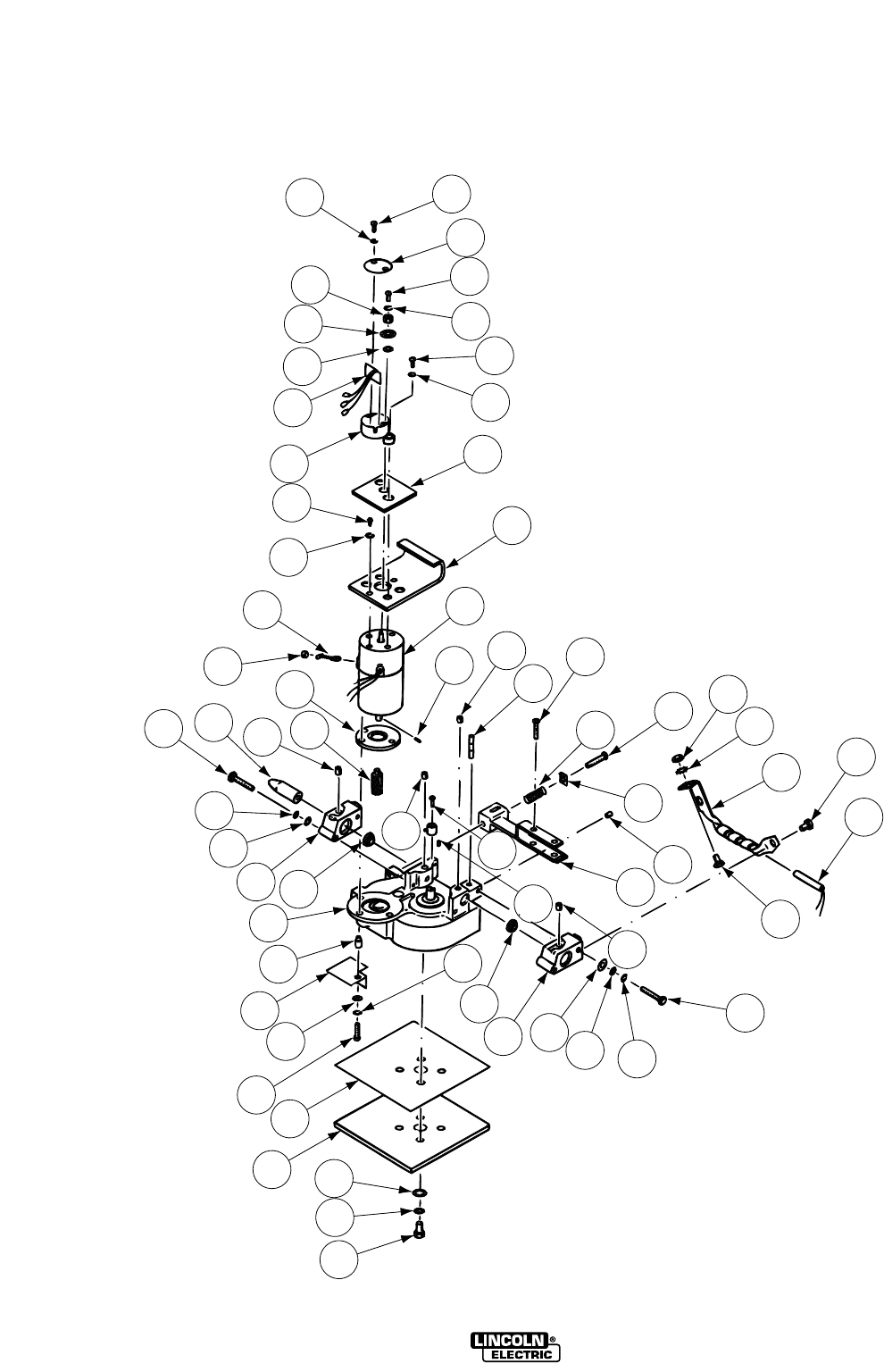
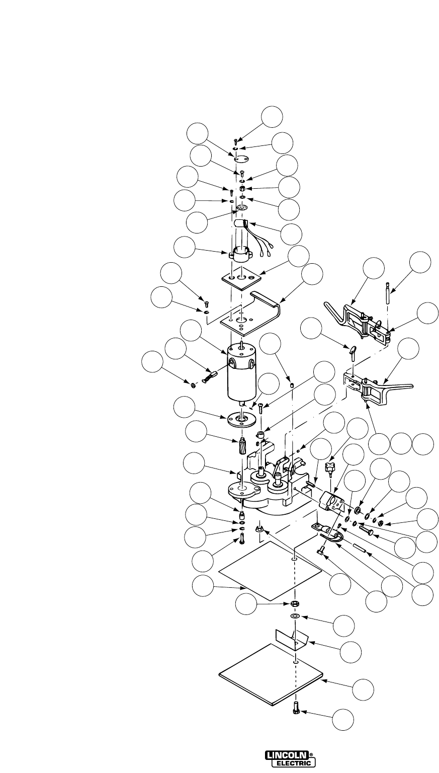
WIRE DRIVE
LN9, LN9H, LN9F, LN9FH
LN9 AND LN9 GMA
Wire Drive Motor & Gear Box Assembly, Includes:
L5743-10 X • • •
Wire Drive Motor & Gear Box Assembly, Includes:
L5743-3
ø
1X•••
Wire Drive Motor & Gear Box Assembly, Includes:
L5743-4 1 • X • •
Wire Drive Motor & Gear Box Assembly, Includes:
L5743-6 1 • • X •
Wire Drive Motor & Gear Box Assembly, Includes:
L5743-7
ø
1•••X
(Items 2, 4C, 4B, 6, 7, 8, 10, 12A, 12B, 12C, 12F, 12J, 12K, 13)
1A #6-32x.375 Round Head Screw CF000003 2 X X X X
1B Lock Washer E106A-13 2 X X X X
2 Cover Assembly T14326 1 X X X X
3A #6-32x.375 Phillips Round Head Screw CF000108 1 X X X X
3B Lock Washer E106A-13 1 X X X X
3C Cap T14246 1 X X X X
4A #8-32x.375 Round Head Screw CF000006 2 X X X X
4B Lock Washer T4291-A 2 X X X X
4C Plain Washer (Not Shown) S9262-3 2 X X X X
5 Plain Washer (Shim) S16268-1 4 X X X X
6 Slotted Disc S16180 1 X X X X
7 Tachometer Pick UP P.C. Board M14700-[ ] 1 X X X X
8 Pick-Up Housing Assembly M13578 1 X X X X
9 Insulator S16267 1 X X X X
10 Heat Sink M13579 1 X X X X
11A #8-32x.375 Round Head Screw CF000006 2 X X X X
11B Lock Washer T4291-A 2 X X X X
12
Drive Motor Assembly,(LN9) includes: (12A & 12B)
L5974-1 1 X • • •
12A Drive Motor, Pinion & Shaft, includes: S16470-1 1 X • • •
(Codes 8420, 8180, 9087, 9134, 9958)
12
Drive Motor Assembly,(LN9F) includes: (12A & 12B)
L5974-2 1 • X • •
12A Drive Motor, Pinion & Shaft, includes: S16470-2 1 • X • •
(Codes 8921, 8670, 9089, 8421, 8670)
12
Drive Motor Assembly,(LN9H) includes: (12A & 12B)
L5974-3 1 • • X •
12A Drive Motor, Pinion & Shaft, includes: M13862-1
ø
1••X•
(Codes 8178, 8422, 8669, 9088)
12
Drive Motor Assembly,(LN9FH) includes: (12A & 12B)
L5974-4 1 • • • X
12A Drive Motor, Pinon & Shaft, includes: M13862-2 1 • • • X
Codes 8423, 8671, 9090)
12B Pinon Gear S15013-4 1 X X • •
12B Pinon Gear S16612 1 • • X X
12C Roll Pin (Gear to Shaft) T9967-33 1 X X X X
12D Brush Cap (Stature) M13312-13 1 X X • •
12D
Brush Cap (Universal) (Early Design 7/8-27 THD)
M9655-7A
ø
1•X••
12D
Brush Cap (Universal) (Present Design 3/4-27 THD)
M9655-7B
ø
1•X••
12D Brush Cap M13274-7 1 • • X X
12E Brush & Spring Assembly (Stature) M13312-12 2 X • • •
12E Brush & Spring Assembly (Universal) M12254-1F 2 • X • •
12E Brush & Spring Assembly (Stature) M13312-12 2 • X • •
12E Brush & Spring Assembly M13274-6 2 • • X X
12F Insulating Bushing T14058 3 X X X X
12G Plain Washer S9262-147 3 X X X X
12H Lock Washer T4291-A 3 X X X X
12J 8-32x1.125 Round Head Screw CF000007 3 X X X X
12K Motor Insulator M13479-1 1 X X X X
12L Insulation (Not Shown) T13911 1 X • X X
12M Speed Clip (Not Shown) T10982-5 1 X X X X
01-01-2007
ITEM DESCRIPTION PART NO. QTY. 123456789
P-127-H.1P-127-H.1
# Indicates a Change This Printing
Sub Assembly Illustration Sub Assembly Illustration Sub Assembly Illustration Sub Assembly Illustration
For LN9, use parts marked “X” in Column 1.
For LN9F, use parts marked “X” in Column 2.
For LN9H, use parts marked “X” in Column 3.
For LN9FH, use parts marked “X” in Column 4.
LN9 AND LN9 GMA
øThis part is obsolete and no longer available.
01-01-2007
P-127-H.2P-127-H.2
Sub Assembly Illustration Sub Assembly Illustration Sub Assembly Illustration Sub Assembly Illustration
13 Gearbox M14310-1 1 X X • •
13 Gearbox M14310-2 1 • • X X
14A
Reed Switch & Energizer Assembly (Below Code 9100)
S14623-2 1 X • X •
14A Reed Switch (Above Code 9100) S12334-43 1 X • • •
14A Reed Switch (Above Code 9100) S12334-45 1 • X • •
14A
Reed Switch & Energizer Assembly (Below Code 9100)
S14623-2 1 X • X •
14A
Reed Switch & Energizer Assembly (Below Code 9100)
S14623-3 1 • X • X
14B Energizer (Above Code 9100) L7392 1 X X • •
14C Self Tapping Screw (Not Shown) S8025-13 1 X X X X
15A Hex Head Cap Screw (Above Code 9100) 1/2-13x1.000 1 X X • •
15A Hex Head Cap Screw (Below Code 9100) 1/4-20x2.00 4 X X X X
15B Lock Washer (Above Code 9100) T9860-2 1 X X • •
15C Hex Jam Nut (Above Code 9100) 1/2-13 1 X X • •
16 Hex Head Cap Screw 1/2-13x.750 2 X X • •
18 Outgoing Conductor Block L6872-2 1 X X X X
19 Plain Washer (Above Code 9100) S9262-120 2 X X • •
20 Plain Washer S9262-23 4 X X X X
21 Lock Washer E106A-2 4 X X X X
22 Hex Head Cap Screw 1/4-20x2.00 4 X X X X
23 Hollow Set Screw S11604-28 4 X X X X
24 Incoming Conductor Block L6872-1 1 X X X X
25 Locator Bushing T12189 2 X X X X
26 Incoming Wire Guide T12272 1 X X X X
27 Insulation M12137 1 X X X X
28 Gear Box Mounting Plate M11460 1 X X X X
29A Hex Head Screw 5/16-18x.75 4 X X X X
29B Plain Washer S9262-121 4 X X X X
29C Lock Washer E106A-14 4 X X X X
30 Yoke Assembly S13454 1 X X • •
30 Yoke Assembly S16731 1 • • X X
31 Pivot Pin T12206-3 1 X X X X
32 Hollow Set Screw S11604-8 1 X X X X
33 Button Head Set Screw T11551-5 1 X X X X
34 Compression Spring T10247-10 1 X X X X
35 Yoke Setting Indicator T12689 1 X X X X
36 Button Head Screw T11551-1 1 X X X X
37 Key (Below Code 10300) M8776-31 1 X X X X
38 Collar Assembly (Below Code 10300) T12341 1 X X X X
38 Collar Assembly (Above Code 10300) S21193 1 X X X X
39 Button Head Socket Screw T11551-6 1 X X X X
40 Feed Unit Mounting Screw (Not Shown) M12616 1 • X • X
41 Round Head Screw (Not Shown) 1/4-20x.625 3 • X • X
42 Lock Washer (Not Shown) E106A-2 3 • X • X
43 Hex Nut (Not Shown) 1/4-20 3 • X • X
* Cover - Black (End of Motor) S16718 1 X X X X
ITEM DESCRIPTION PART NO. QTY. 123456789
# Indicates a Change This Printing
For LN9, use parts marked “X” in Column 1.
For LN9F, use parts marked “X” in Column 2.
For LN9H, use parts marked “X” in Column 3.
For LN9FH, use parts marked “X” in Column 4.
LN9 AND LN9 GMA

NOTES
LN9 AND LN9 GMA
P-127-JP-127-J
Part Numbers Part Numbers Part Numbers Part Numbers
1-28-2002
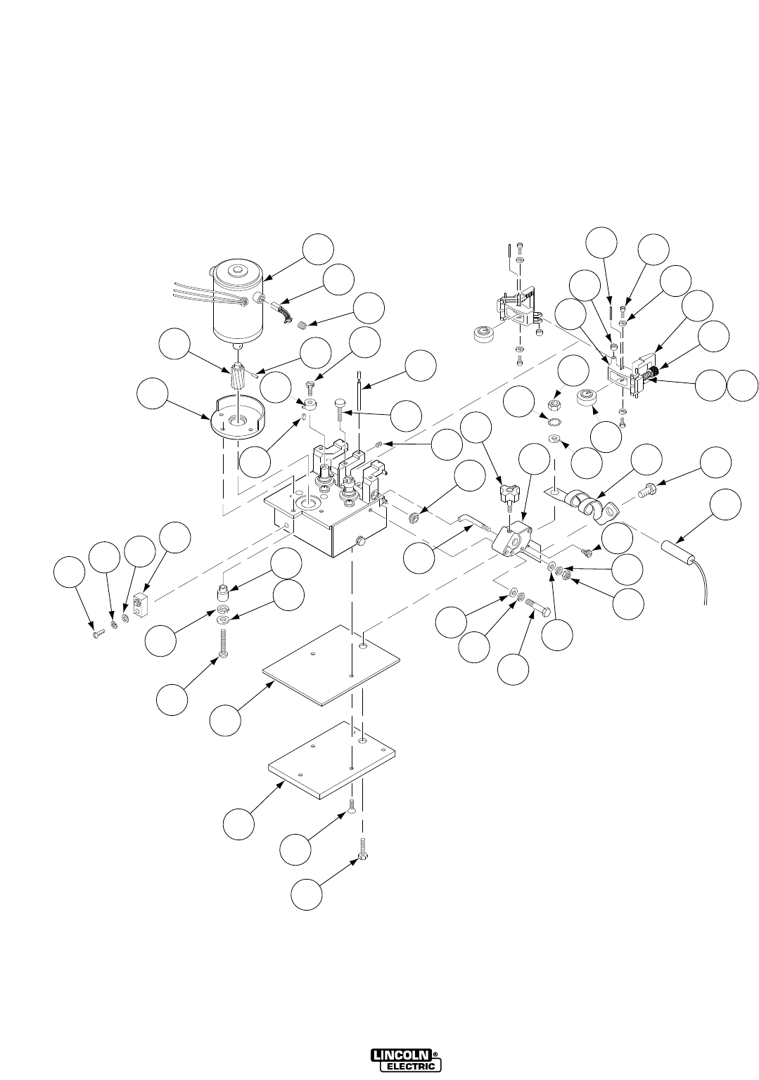
WIRE DRIVE, MOTOR & GEAR BOX ASSEMBLY
LN9 GMA & LN9F GMA
(4-Roll)
LN9 AND LN9 GMA
1A
1B
1C
1F
1E
2
7C
7B
7A
23
5
6
10
8
9C
9B
9A 3A
3C
3B
3D
19
20
21
18A
25
22K
22D 22G
22F
22H
22J
22E 22N
18D
18B
18C
22A
17
16B
16A
15
12D
12B
12C
12A
12B
12C
11
14
13

05-06-2006
ITEM DESCRIPTION PART NO. QTY. 123456789
Gear Box Asbly (LN9F GMA 4 Roll), Includes:
G2262-3 1 X
Gear Box Asbly (LN9 GMA 4 Roll), Includes:
G2262-2 1 X
1 Drive Motor Asbly (LN9 GMA), Includes: M15078-1 1 X
1 Drive Motor Asbly (LN9F GMA), Includes: M15078-3 1 X
1A Drive Motor, Includes: NSS 1X
1B
Brush & Spring Asbly (Universal Electric)
M13274-6 2 X
1B
Brush & Spring Asbly (Specialty Motors)
M16718-F
ø
2X
1B
Brush & Spring Asbly (Stature Electric)
M15114-1K 2 X
1C Brush Cap (Universal Electric) M13274-7 2 X
1C Brush Cap (Specialty Motors) M14907-1G 2 X
1C Brush Cap (Stature Electric) M15114-1L 2 X
1D Plain Washer (Not Shown) S9262-70 1 X
1E Pinion Gear S17980-1 1 X
1F Roll Pin T9967-33 1 X
1G Ring Magnet (Not Shown) S18011 1 X
2 Motor Insulator / Spacer M16803 1 X
3A Bushing T14058-1 3 X
3B Plain Washer S9262-147 3 X
3C Lock Washer T4291-A 3 X
3D #8-32 x 1.50 RHS CF000119 3 X
5 Thumb Screw S19924 3 X
6 Set Screw S11604-6 1 X
7A Sems Screw T10082-26 2 X
7B Collar Assembly (Below Code 10300) T12341 2 X
7B Collar Assembly (Above Code 10300) S21193 2 X
7C Key (Below Code 10300) M8776-82 2 X
8 Hall Effect Switch (LN9 GMA) S18160-1 1 X
8 Hall Effect Switch (LN9F GMA) S18160-1 1 X
9A #10-24 x 1.00 RHS CF000038 1 X
9B Lock Washer E106A-1 1 X
9C Plain Washer S9262-27 1 X
10 Locator Bushing T14031 1 X
11 Bent Bolt S20629-1 1 X
12A Hex Head Screw 1/4-20x1.750 2 X
12B Lock Washer E106A-2 2 X
12C Plain Washer S9262-23 2 X
12D 1/4-20 Hex Nut CF000017 1 X
13 Conductor Block M13972-2 1 X
14 Molded Hand Screw T13858 1 X
15 Sems Screw T10082-4 1 X
16A Reed Switch Assembly (LN9F GMA 4 Roll) S12334-47 1 X
16A Reed Switch Assembly (LN9 GMA 4 Roll) S12334-43 1 X
16B Reed Switch Energizer M15173 1 X
17 1/2-13 x .750 HHCS CF000029 1 X
18A 1/2-13 x 1.75 HHCS CF000277 1 X
18B Lock Washer T9695-8 1 X
18C Plain Washer (LN9 GMA) S9262-1 1 X
18C Plain Washer (LN9F GMA) S9262-125 1 X
18D 1/2-13 HJN CF000054 2 X
19 Gear Box Insulation (Lower) T11472-26 1 X
(Not used on LN9 GMA 4 Roll)
P-127-J.1P-127-J.1
Sub Assembly Illustration Sub Assembly Illustration Sub Assembly Illustration Sub Assembly Illustration
LN-9 AND LN-9 GMA
#
øThis part is obsolete and no longer available.
NSS - Not Sold Separately

02-13-2006
LN9 AND LN9 GMA
ITEM DESCRIPTION PART NO. QTY. 123456789
20 Gear Box Mounting Plate S20331 1 X
21 1/4-20x.625 Flat Head Screw CF000345 2 X
22 Swing Arm Assembly, Includes: M16445 2 X
22A Bearings & Shaft Assembly T13244-1 1 X
22B Roll Pin (Not Shown) T9967-25 1 X
22C Plain Washer (Not Shown) S9262-60 1 X
22D Pin M8809-122 1 X
22E Spring T10247-11 1 X
22F Plain Washer S9262-3 2 X
22G Socket Head Screw T9447-21 2 X
22H Release Assembly S19965 1 X
22J Knob S19922 1 X
22K Swing Arm M16446 1 X
22L Pivot Block Shaft (Not Shown) S19921 1 X
22M Spacer (Not Shown) S20244 2 X
22N Tension Rod S19920 1 X
23 Pin S19828 1 X
24
Connection Box Assembly LN9F GMA (4 Roll)
M15238-1 1 X
(Not Shown)
Female Connector T11591-3 1 X
Solenoid Valve Assembly M15234 1 X
Number Plate T10726-153 1 X
Hose Clamp S10888-35 1 X
Connector T14557-3 1 X
Connector and Lead Assembly S13100-73 1 X
Terminal Strip S14530-10 1 X
Terminal Strip S14872-1 1 X
Warning Label T9274-4 1 X
25 Swing Arm Spacer S19923 1 X
P-127-J.2P-127-J.2
Sub Assembly Illustration Sub Assembly Illustration Sub Assembly Illustration Sub Assembly Illustration

NOTES
LN9 AND LN9 GMA
P-127-KP-127-K
Part Numbers Part Numbers Part Numbers Part Numbers
10-26-2007
7
8
10B
10B
10A
10A
9
11A
11A
11B
11B
11C
11C
5
6
15D
15D
15B
15B
15C
15C
13B
13B
14
14
13A
13A
17
17
19
19
16
16
18C
18C
18B
18B
18A
18A
20
20
21
21
15A
15A
22B
22B
22C
22C
22A
22A
4
3D
3D
3C
3C
3B
3B
3A
3A
23
23
24C
24C
24B
24B
24A
24A
25
25
12D
12D
12E
12E
12C
12C
12B
12B
12A
12A
1B
1B
1C
1C
1F
1F
1E
1E
2
1A
1A
Old Style
Old Style
10
10
WIRE DRIVE, MOTOR & GEAR BOX ASSEMBLY
LN9 GMA & LN9F GMA
(2-Roll)
LN9 AND LN9 GMA

ITEM DESCRIPTION PART NO. QTY. 123456789
P-127-K.1P-127-K.1
# Indicates a Change This Printing
Sub Assembly Illustration Sub Assembly Illustration Sub Assembly Illustration Sub Assembly Illustration
1 Drive Motor Asbly (LN9 GMA), Includes: M15078-1 1 X
1 Drive Motor Asbly (LN9F GMA), Includes: M15078-3 1 X
1A Drive Motor NSS 1X
1B
Brush & Spring Asbly (Universal Electric)
M13274-6 2 X
1B
Brush & Spring Asbly (Specialty Motors)
M14996-F 2 X
1B
Brush & Spring Asbly (Stature Electric)
M15114-1K 2 X
1C Brush Cap (Universal Electric) M13274-7 2 X
1C Brush Cap (Specialty Motors) M14907-G 2 X
1C Brush Cap (Stature Electric) M15114-1L 2 X
1D Plain Washer (Not Shown) S9262-70 1 X
1E Pinion Gear S17980-1 1 X
1F Roll Pin T9967-33 1 X
1G Ring Magnet (Not Shown) S18011 1 X
2 Motor Insulator M13479-4 1 X
3A Bushing T14058 3 X
3B Plain Washer S9262-3 3 X
3C Lock Washer T4291-A 3 X
3D #8-32x1.125 RHS CF000007 3 X
4 Gear Box L7255-1 1 X
5 Thumb Screw T15046 2 X
6 Drive Screw S8025-19 1 X
7 1/4-20x1.25 HHCS CF000069 1 X
8 Pivot Spacer S10918-7 1 X
9 Plain Washer S9262-103 1 X
10 Quick Release Asbly (Old Style), Includes: M15023 1 X
10A Latch Knob T13858-1 1 X
10B Quick Release Assembly (Current Style) M19266-1 1 X
11A Sems Screw T10082-26 1 X
11B Collar Assembly (Below Code 10300) T12341 1 X
11B Collar Assembly (Above Code 10300) S21193 1 X
11C Key (Below Code 10300) M8776-82 1 X
12A Idle Roll Assembly S16666-1 1 X
12B Bearing T13244 1 X
12C Self Taping Screw S8025-19 1 X
12D Speed Clip T10982-7 1 X
12E Groove Pin T10580-9 1 X
13A Reed Switch Assembly S12334-43 1 X
13B Reed Switch Energizer M15173 1 X
14 1/2-13x.75 HHCS CF000020 1 X
15A 1/2-13x1.75 HHCS CF000277 1 X
15B Lock Washer T9695-8 1 X
15C Plain Washer (LN-9 GMA) S9262-1 1 X
15C Plain Washer (LN-9F GMA) S9262-125 1 X
15D 1/2-13 HJN CF000054 2 X
16 Conductor Block S17798 1 X
17 Knob T13858 1 X
18A 1/4-20x1.75 HHCS CF000016 2 X
18B Lock Washer E106A-2 2 X
18C Plain Washer S9262-23 2 X
19 Locator Bushing T14031 1 X
10-26-2007
NSS - Not Sold Separately
10-26-2007
LN9 AND LN9 GMA
ITEM DESCRIPTION PART NO. QTY. 123456789
20 Gear Box Insulation T15049 1 X
21 Gear Box Mounting Plate S17979 1 X
22A 1/4-20x.75 HHCS CF000014 2 X
22B Lock Washer E106A-2 2 X
22C Plain Washer S9262-98 2 X
23 Switch Mounting Housing Assembly S21227 1 X
24A #10-24x1.00 RHS CF000038 1 X
24B Lock Washer E106A-1 1 X
24C Plain Washer S9262-27 1 X
25 Sems Screw T10082-4 1 X
26 Connection Bolt Insulation (Not Shown) S18169 1 X
27 Hall Effect Switch, (Not Shown) S18160-1 1 X
28 Gas Solenoid & Support (Not Shown) M15095-1 1 X
P-127-K.2P-127-K.2
# Indicates a Change This Printing
Sub Assembly Illustration Sub Assembly Illustration Sub Assembly Illustration Sub Assembly Illustration

NOTES
LN9 AND LN9 GMA
P-127-LP-127-L
Part Numbers Part Numbers Part Numbers Part Numbers
1-17-97
1A
1B
2
3A
3B
3C
4A
4B
5
6
7
89
10
11A
11B
14A 14B
14D
14A
12A
12E
12D
12K
12C
15
12B
13
12F
12G
12H
12J
14C
14E 14F 14G
23 21G
21E
21D
21H
21C
22A
20B
20A 21A
21B
17B
17C
17A
17F
17G
17D
17H
17D
16
17E
19B
19A
19C
14H
WIRE DRIVE, MOTOR & GEAR BOX ASSEMBLY
LN9 & LN9F
(4-Roll Drive)
LN9 AND LN9 GMA

01-01-2007
LN9 AND LN9 GMA
ITEM DESCRIPTION PART NO. QTY. 123456789
Wire Drive and Gear Box Assembly G2223-1
(LN9F, 4-Roll), includes:
Wire Drive and Gear Box Assembly G2223-4
(LN9, 4-Roll), includes:
1A #6-32x.375 Round Head Screw CF000003 2 X
1B Lock Washer E106A-13 2 X
2 Cover Assembly T14326 1 X
3A #6-32x.375 Phillips Round Head Screw CF000108 1 X
3B Lock Washer E106A-13 1 X
3C Cap T14246 1 X
4A #8-32x.375 Round Head Screw CF000006 2 X
4B Lock Washer T4291-A 2 X
4C Plain Washer (Not Shown) S9262-3 2 X
5 Plain Washer (Shim) S16268-1 4 X
6 Slotted Disc S16180 1 X
7 Tachometer Pick Up P.C. Board M14700-[ ] 1 X
8 Pick-Up Housing Assembly M13578 1 X
9 Insulator S20425 1 X
10 Heat Sink M13579 1 X
11A #8-32x.375 Round Head Screw CF000006 2 X
11B Lock Washer T4291-A 2 X
12A
Drive Motor Assembly (LN9, 4-Roll), includes:
L5974-8 1 X
Drive Motor, Pinion & Shaft, includes: (LN9, 4-Roll)
S16470-1 1 X
12A
Drive Motor Assembly (LN9F, 4-Roll), includes:
L5974-2 1 X
Drive Motor, Pinion & Shaft, includes: (LN9F, 4-Roll)
S16470-2 1 X
12B Pinion S15013-4 1 X
12C Roll Pin (Gear to Shaft) T9967-33 1 X
12D Brush Cap (Stature Electric) M13312-13 2 X
12D Brush Cap (Universal Electric) M9655-7B
ø
2X
12E Brush & Spring Assembly (Stature Electric) M13312-12 2 X
12E Brush & Spring Assembly (Universal Electric) M12254-1F 2 X
12F Insulating Bushing T14058-1 3 X
12G Plain Washer S9262-147 3 X
12H Lock Washer T4291-A 3 X
12J 8-32x1.125 Round Head Screw CF000007 3 X
12K Motor Insulator M13479-1 1 X
12L Insulation (Not Shown) T13911 1 X
12M Speed Clip (Not Shown) T10982-5 1 X
13 Gearbox G2232 1 X
14A Swing Arm M16373 2 X
14B Swing Arm Pin S19828 1 X
14C Set Screw S11604-6 1 X
14D Quick Release Pin S19829 2 X
14E Pivot Block Shaft S19827 2 X
14F Pivot Block S19826 2 X
14G Roll Pin T9967-27 2 X
14H Swing Arm L8364 1 X
15A Cam (Not Shown) S19824 4 X
15B Roll Pin (Not Shown) T9967-5 4 X
16 Screw & Handle Assembly T13858 1 X
P-127-L.1P-127-L.1
# Indicates a Change This Printing
Sub Assembly Illustration Sub Assembly Illustration Sub Assembly Illustration Sub Assembly Illustration
øThis part is obsolete and no longer available.

ITEM DESCRIPTION PART NO. QTY. 123456789
17A Conductor Block S19830 1 X
17B 1/4-20x1.50 Hex Head Cap Screw CF000141 1 X
17C Plain Washer S9262-23 2 X
17D Lock Washer E106A-2 2 X
17E Stud T9781-129 1 X
17F Insulating Tube T7028-13 1 X
17G Insulating Washer S10773-53 1 X
17H 1/4-20 Hex Nut CF000017 1 X
18 Locator Bushing (Not Shown) S19825 1 X
19A Collar Assembly (Below Code 10300) T12341 2 X
19A Collar Assembly (Above Code 10300) S21193 1 X
19B Button Head Socket Screw T11551-6 2 X
19C Key (Below Code 10300) M8776-31 2 X
20A Reed Switch Energizer M16370 1 X
20B 1/2-13x.75 Hex Head Cap Screw CF000020 1 X
21A Reed Switch Assembly S12334-43 1 X
21B Self Tapping Screw S8025-13 1 X
21C 1/2-13x1.75 Hex Head Cap Screw CF000026 1 X
21D Plain Washer S9262-1 1 X
21E Flange Nut T3960 1 X
21F Lock Washer (Not Shown) T9695-8 1 X
21G 1/2-13 Hex Jam Nut CF000054 1 X
21H Insulation S18169 1 X
22A Gearbox Mounting Plate S19831 1 X
22B 5/16-18x.75 Hex Head Cap Screw (Not Shown) CF000040 4 X
22C Plain Washer (Not Shown) S9262-121 4 X
22D Lock Washer (Not Shown) E106A-14 4 X
23 Insulation M16372 1 X
P-127-L.2P-127-L.2
# Indicates a Change This Printing
Sub Assembly Illustration Sub Assembly Illustration Sub Assembly Illustration Sub Assembly Illustration
01-01-2007
LN9 AND LN9 GMA

NOTES
LN9 AND LN9 GMA
P-127-MP-127-M
1
2
3
33
29
30
525
23
26
22
17
18
19
14
11109
Part Numbers Part Numbers Part Numbers Part Numbers
1-96
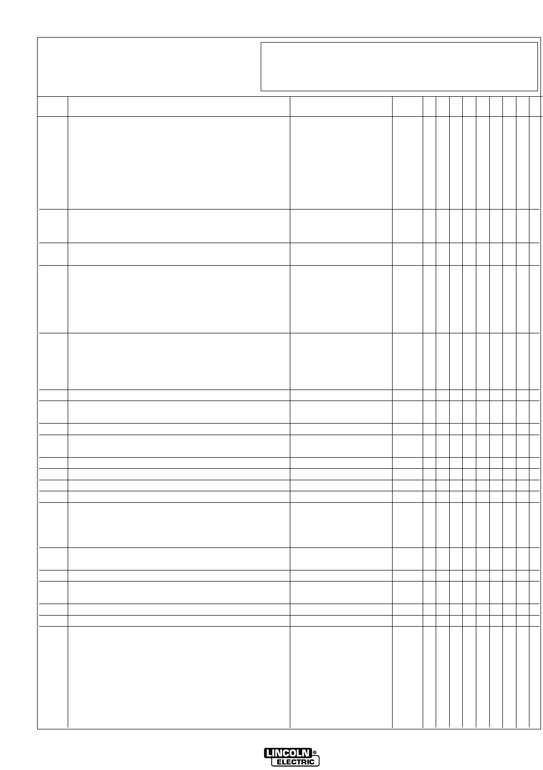
CONTROL BOX
LN9F, LN9FH & LN9F GMA
L7201
6-28-85M
LN9 AND LN9 GMA

10-04-2005
ITEM DESCRIPTION PART NO. QTY. 123456789
1 Control Box Welded Assembly M13655-1 1 X
(LN-9F Above Code 9100)
1 Control Box Welded Assembly M13655 1 X
(LN9F & 9FH Below Code 9100)
1 Control Box Welded Assembly M13655-3 1 X
(LN-9F GMA)
2 Resistor S10404-75 1 X
#10-24 x 5.00 RHS CF000045 1 X
Insulating Washer T4479-A 2 X
3 Sub Panel Assembly See P-127-S 1 X
4 Work Jack (Below Code 8400)(Not Shown) T14280 1 X
5 Door Assembly See P-127-N 1 X
9 Circuit Breaker (LN9F) T12287-10 1 X
9 Circuit Breaker (LN9FH & LN9F GMA) T12287-8 1 X
10 Push Button Switch T14200 1 X
11 Terminal Strip S13323-5 1 X
Number Plate T10726-130 1 X
14 Plug Button T13597-1 1 X
17 Reed Switch Assembly S12334-26 1 X
18 Resistor T12731-34F 1 X
19 Terminal Strip T10707 1 X
22 Transformer Assembly S14651-6
ø
1X
23 Voltage Printed Circuit Board Assembly L6084 1 X
(Below Code 9000)
23 Voltage Printed Circuit Board Assembly L6084-[ ] 1 X
(Above 9000)
Voltage Printed Circuit Board Insulation S16364 1 X
25 Warning Decal T13470 1 X
26 Patent Decal S13232 1 X
27 Start Printed Circuit Board Assembly M13750 1 X
(Below Code 9000 Only) (Not Shown)
29 Potentiometer S16296-1 2 X
30 Felt Washer T14034 2 X
Insulating Tube T7028-241 2 X
Knob T14091 2 X
33 Warning Label S16722-3A 1 X
Parts (Not Shown)
Tachometer Connector (Not Used On LN9F GMA)
S12021-18 1 X
Input Connector S12021-12 1 X
Output Connector (LN9F & 9FH) S12021-10 1 X
Output Connector (LN9F GMA) S12021-37 1 X
P-127-M.1P-127-M.1
# Indicates a Change This Printing
Sub Assembly Illustration Sub Assembly Illustration Sub Assembly Illustration Sub Assembly Illustration
#
LN9 AND LN9 GMA
øThis part is obsolete and no longer available.
Note: When ordering new printed circuit boards indicate the dash number [ ] of the “Old” board that
is to be replaced. This will aid Lincoln in supplying the correct and latest board along with
any necessary jumpers or adapters. The dash number brackets [ ] have purposely been left
blank so as to eliminate errors, confusion and updates.
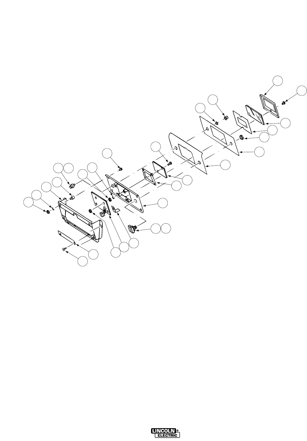
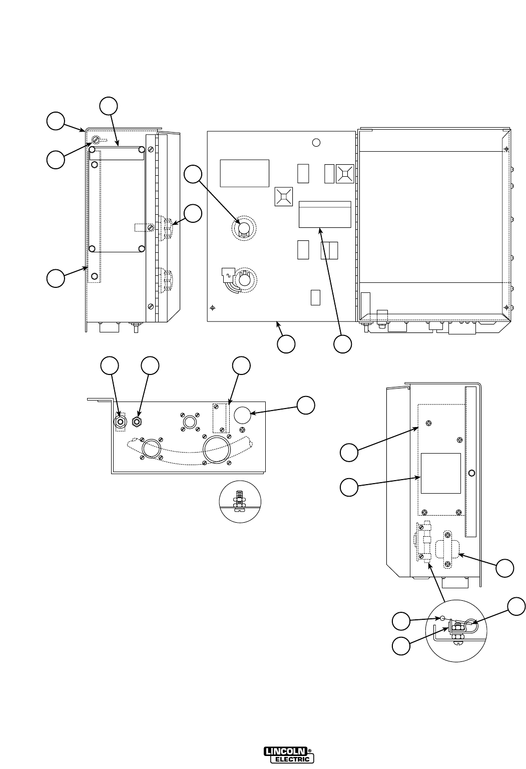
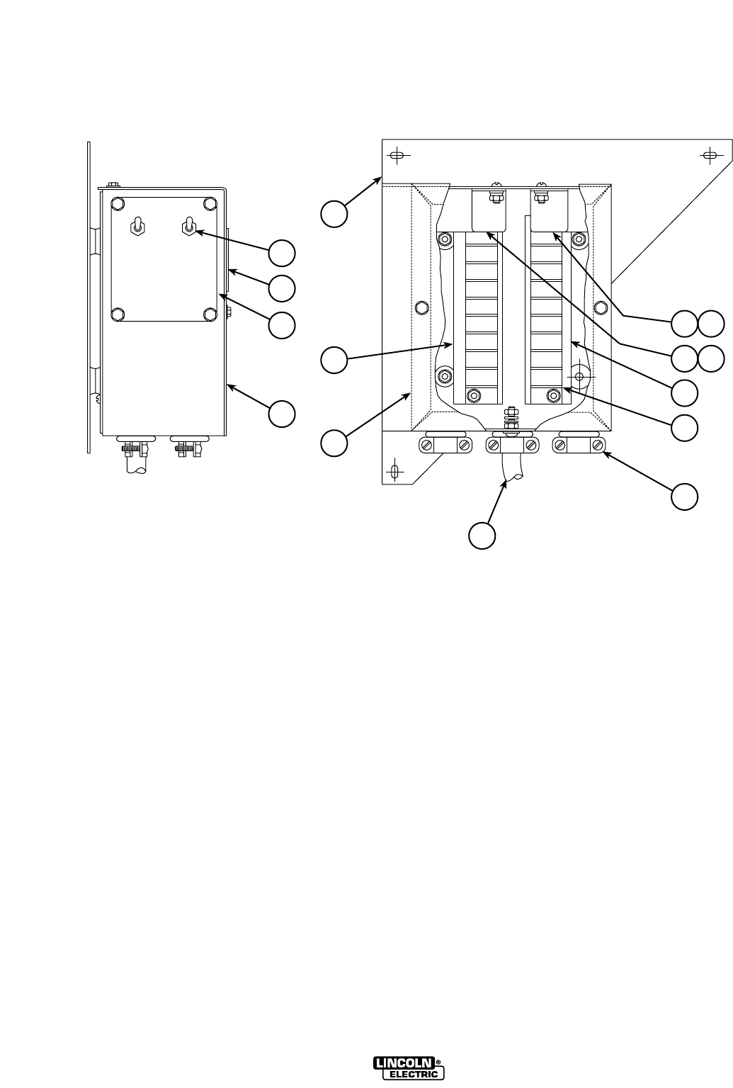
P-127-NP-127-N
1 2 7 8
3
9
151413
654
17 18 19
22
20
21
A
A
FRONT VIEW
REAR VIEW
Part Numbers Part Numbers Part Numbers Part Numbers
1-96
DOOR ASSEMBLY
LN9F, LN9FH, & LN9F GMA
L7091
2-1-85B
LN9 AND LN9 GMA
Door Assembly, Includes: L6023 1 X • • •
Door Assembly (LN9F Only), Includes: L6185-1 1 • X • •
Door Assembly (LN9FH Only), Includes: L6185-2 1 • X • •
Door Assembly (LN9F Metric), Includes: L6667-1 1 • X • •
Door Assembly (LN9FH Metric), Includes: L6667-2 1 • X • •
Door Assembly (LN9F Metric), Includes: L7091-1 1 • • X •
Door Assembly (LN9FH Metric), Includes: L7091-2 1 • • X •
Door Assembly (LN9F GMA), Includes: L7367 1 • • • X
1 Door S16336 ø1X••X
1 Door S16336-2 1 • • • X
1 Door S16336-1 1 • X X •
2 Button Plug T13597-2 1 X X X •
2 Button Plug T13597-2 4 • • • X
3 Nameplate L6005 1 X • • •
3 Nameplate (LN9F Only) L6183 ø 1•X••
3 Nameplate (LN9FH Only) L6184 ø1•X••
3 Nameplate (LN9F Metric) L6183-1 1 • X X •
3 Nameplate (LN9F GMA) L7348 1 • • X •
3 Nameplate (LN9FH Metric) L6184-1 1 • X X •
4 Meter & P.C. Board Assembly M13650 1 X • • •
4 Meter & P.C. Board (LN9F Only) L6181-[ ] 1 • X • •
4 Meter & P.C. Board (LN9FH Only) L6181-[ ] 1 • X • •
4 Meter & P.C. (LN9F Metric) L6687-[ ] 1 • X X •
4 Meter & P.C. Board (LN9FH Metric & LN9F GMA) L6688-[ ] 1 • X X X
5 Switch (Polarity) T13111 1 X X X X
6 Switch & Transient Protector Assembly T14535 1 X X X •
6 Switch (Direction) T10800-7 1 • • • X
7 Bezel Assembly S17414 1 • • X X
8 Meter Shield (Std. Clear Lens) T14771 1 X X • •
8 Filter Lens T14807-1 1 • • X X
9 Meter Shield Frame M13572 1 X X X X
13 Lock Tab T10045-40 1 X X X X
14 Dial Plate S16277 1 X X X X
15 Security Panel S16275 1 X X X X
17 Switch (LN9F Only) T13111 1 X X • •
17 Switch (LN9FH Only) T13381-2 1 • X • •
17 Switch (LN9FH Metric, LN9F GMA), Includes: S16670-5 1 • X X X
Knob T13639 1 • X X X
18 Switch T10800-4 1 X • • •
18 Switch (Hot-Cold Interlock) T10800-12 1 • X X X
19 Switch & Actuator Assembly T14751-1 1 X X X X
20 Meter & Pin Assembly S16636 1 • X • •
20 Digital Meter P.C. Board M14490-[ ] 1 • • X X
21 P.C. Board Spacer M14537 1 • • X X
22 Printed Circuit Board Insulation T14468 1 X • X X
Items Not Shown:
Fiber Washer S10773-15 2 X X X X
Felt Washer T14034 2 X X X X
Insulating Tube T7028-241 2 X X X X
Potentiometer S16296-1 2 X X X X
Knob T14091 2 X X X X
10-04-2005
ITEM DESCRIPTION PART NO. QTY. 123456789
P-127-N.1P-127-N.1
# Indicates a Change This Printing
Sub Assembly Illustration Sub Assembly Illustration Sub Assembly Illustration Sub Assembly Illustration
For Codes Below 8000, use parts marked “X” in Column 1.
For Codes 8000 to 8700, use parts marked “X” in Column 2.
For Codes Above 8700, use parts marked “X” in Column 3.
For LN9F GMA, use parts marked “X” in Column 4.
LN9 AND LN9 GMA
#
øThis part is obsolete and no longer available.
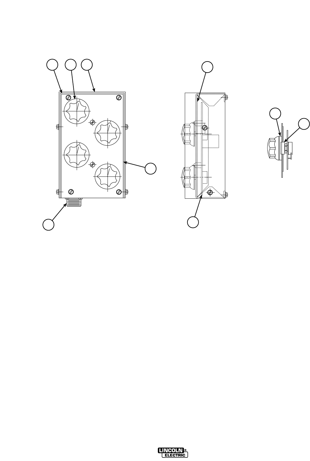
K317 DUAL PROCESS KIT
P-127-PP-127-P
2
3
4
6
7
5
1
16 17
14 15
13
12
10
8
Part Numbers Part Numbers Part Numbers Part Numbers
1-96
M13524
10-8-82G
LN9 AND LN9 GMA

01-01-2007
LN9 AND LN9 GMA
ITEM DESCRIPTION PART NO. QTY. 123456789
1 Mounting Bracket M13696 1 X
2 Toggle Switch T13381 2 X
3 Caution Decal T13470 1 X
4 Nameplate S16391 1 X
5 Number Plate T10726-125 1 X
6 Cover M13692 1 X
7 Case Welded Assembly S16191 1 X
8 Control Cable S16190 1 X
10 Box Connector T9639-1 2 X
12 Terminal Strip S8542-1 2 X
13 Number Plate T10726-126 1 X
14 Relay (1CR) T13845-3 1 X
15 I.D. Sticker T12286-1 1 X
16 Relay (2CR) S14293-7 1 X
17 I.D. Sticker T12286-2 1 X
P-127-P.1P-127-P.1
# Indicates a Change This Printing
Sub Assembly Illustration Sub Assembly Illustration Sub Assembly Illustration Sub Assembly Illustration
K319 DUAL PROCEDURE KIT
P-127-RP-127-R
Part Numbers Part Numbers Part Numbers Part Numbers
1-96
L6055
11-5-82M
1 2 3
6
75
15
10
9
LN9 AND LN9 GMA

ITEM DESCRIPTION PART NO. QTY. 123456789
1 Control Box L6054 1 X
2 Rheostat Knob T10491 4 X
3 Cover M13652 1 X
4 Insulation S16384 1 X
5 P.C. Board Assembly M13679-[ ] 1 X
6 Nameplate S16382 1 X
7 Receptacle Assembly S13100-63 1 X
9 Insulating Tube T14767 4 X
10 Shaft Seal T14034 4 X
Insulating Tube T7028-241 2 X
Items Not Shown:
Gun Mounted Selector Switch & Cable Assembly,
Includes: S16383 1 X
3 pin Amphenol Connector S12020-16 1 X
Cable Clamp S12024-4 1 X
Extension Cable Assembly, Includes: M13681 1 X
3 socket Amphenol Connector S12023-8 1 X
3 pin Amphenol Connector S12020-16 1 X
Cable Clamp S12024-4 2 X
10-04-2005
P-127-R.1P-127-R.1
# Indicates a Change This Printing
Sub Assembly Illustration Sub Assembly Illustration Sub Assembly Illustration Sub Assembly Illustration
LN9 AND LN9 GMA
#
P-127-SP-127-S
6
3
1
4
5
2
Part Numbers Part Numbers Part Numbers Part Numbers
1-96
M13647
2-10-95D
INSTRUMENT PANEL
LN9F, LN9FH & LN9F GMA
LN9 AND LN9 GMA

Sub Panel Assembly, Includes: (Below Code 8000)
M13647 1 X
Sub Panel Assembly, Includes:
(Above Code 8000 LN9F & FH) M13647-1 1 X
Sub Panel Assembly, Includes: (LN9F GMA) M13647-1 1 X
1 Sub Panel (Below Code 8000) M13626 1 X
Sub Panel (Above Code 8000) M13872-1 1 X
2 Control Printed Circuit Board (LN9F & FH) L6019 1 X
2 Control Printed Circuit Board (LN9F GMA) L7253-[ ] 1 X
(Below Code 10352)
2 Control Printed Circuit Board (LN9F GMA)
(Above Code 10352) L10068-[ ] 1 X
Plastic Expansion Nut S14020-3 4 X
Self Tapping Screw S8025-71 4 X
3 Power Printed Circuit Board (LN9F & FH) L6043-[ ] 1 X
3 Control Printed Circuit Board (LN9F GMA) L7265-2 1 X
Plastic Expansion Nut S14020-3 5 X
Self Tapping Screw S8025-71 5 X
4
Trigger Printed Circuit Board (Below Code 8000)
M13630 1 X
4
Trigger Printed Circuit Board (Above Code 8000)
M13861-[ ] 1 X
Plastic Expansion Nut S14020-3 3 X
Self Tapping Screw S8025-71 3 X
5 Transformer Assembly S16282 1 X
5
Transformer Assembly (Used with Trigger Board)
S16282-1 1 X
6 Power Board Relay S13929-6 1 X
ITEM DESCRIPTION PART NO. QTY. 123456789
01-01-2007
P-127-S.1P-127-S.1
# Indicates a Change This Printing
Sub Assembly Illustration Sub Assembly Illustration Sub Assembly Illustration Sub Assembly Illustration
LN9 AND LN9 GMA
.068”-5/64 Cored KP653-3/32 KP2139-8
S14541-3/32
(2 Req”d) KP2125-5 KP2125-8 S13342-3/32
(.062) 1/16
Cored or Solid* KP653-1/16 KP2139-5 S14541-1/16 (2 Req”d) KP2125-3 KP2124-5 None
.045 & .052” KP653-052C KP2139-3
S14542-052
KP1999-1 KP2124-3 None
.045” -.052”
Cored KP653-052C KP2139-3 M17301 (2 Req”d) KP1999-1 KP2124-3 None
.023” -.035” Solid
KP653-035S KP2139-3
M17301-035
KP2125-1 KP2124-1 T14984
.030 Solid KP653-030S KP2139-1
M17301-030
KP2125-1 KP2124-1 T14984
.035 Cored KP653-030C KP2139-3
M17301-030
KP2125-1 KP2124-1 T14984
.035 Solid KP653-035S KP2139-3 M17301-035 KP2125-1 KP2124-1 T14984
7/64 Cored KP653-7/64H KP2139-8 M17302-120 KP2125-4 KP2124-7 None
.120 Cored KP653-120C KP2139-7 M17302-120 KP2125-4 KP2124-7 None
1/16A KP654-1/16A KP2139-5 S17092-1/16A KP2125-3 KP2124-5 Wing Screw T9078-3
3/64A KP654-3/64A KP2139-3 S17092-035A KP1999-1 KP2124-1 Wing Screw T9078-3
.035A KP654-035A KP2139-1 S17092-035A KP2125-1 KP2124-1 Wing Screw T9078-3
* Can be used for .052
10-10-2003
Conversion Kit Chart
LN9 GMA (2 Roll Drive)
LN9 GMA
(4 Roll Drive)
P-127-T
P-127-T
WIRE
CONVERSION
KIT
INCOMING
GUIDE
DRIVE
ROLL
OUTGOING
GUIDE TUBE
DRIVE ROLL
SPACER
OUTGOING
GUIDE INSERT
.023 - .025S KP655-025S KP2139-2 M17301-025 T14984 KP2125-1 KP2124-1 KP2114-1
.030 Solid KP655-030S KP2139-2 M17301-030 T14984 KP2125-1 KP2124-1 KP2114-1
.035
Cored
KP655-035C KP2139-4 M17302-035 None KP2125-1 KP2124-1 KP2114-1
.035 Solid KP655-035S KP2139-4 M14932 (2 Req”d) T14984 KP2125-1 KP2124-1 KP2114-1
.045 & .052” Solid
KP655-052S KP2139-4 S14542-052 (2 Reqʼd) None KP1999-1 KP2124-3 KP2114-2
.045 - .052” Cored
KP655-052C KP2139-4 S14541-052 (4 Reqʼd) None KP1999-1 KP2124-3 KP2114-2
1/16 Solid KP655-1/16 KP2139-6 S14541-1/16 (4 Reqʼd) None KP2125-3 KP2124-5 KP2114-3
.068 - 3/32 Cored
KP655-3/32 KP2139-9 S14541-
3/32
(4 Reqʼd)
S13342-3/32
KP2125-5 KP2124-8 KP2114-5
.120
Cored
KP655-120C T13467-120F M17302-120 None KP2125-4 KP2124-7 KP2114-4
1/16A KP656-1/16A KP2132-1 S17092-1/16A (2 Reqʼd) None KP2137-2 S14349-1/16L KP2115
3/64A KP656-3/64A KP2132-2 S17092-3/64A (2 Reqʼd) None KP2137-3 S14349-045 L KP2115-2
.035A KP656-035A S21273-3/64F S17092-035F(2 Reqʼd) None KP2137-1 S14349-045L KP2115-2
WIRE
SIZE
GUIDE
CONVERSION
KIT
INCOMING
GUIDE TUBE
ASSEMBLY
DRIVE
ROLL
OUTGOING
GUIDE TUBE
MIDDLE
INSERT
L(LOOSE)
OUTGOING
GUIDE INSERT
SPACER
(2 REQʼD)
LN9 AND LN9 GMA
#Indicates a Change This Printing
Some Drive Rolls Available Only in a Kit.
#
#
#
#
#
#
#
#
#
#
#
#
#
#
#
#
#
#
#
#
#
#
#
#
#

NOTES
LN9 AND LN9 GMA
K318 DUAL PROCESS CONTACTOR KIT
P-127-UP-127-U
Part Numbers Part Numbers Part Numbers Part Numbers
1-96
22
21
23
25
26
29
30
28
24
27
2
32
35191817161514
3
1
AA
456
831 20 36
1211
9
33
L6224
10-8-82G
LN9 AND LN9 GMA

1 Case M13673-1
ø
1X•
1 Case M13673-2 1 • X
2 Wraparound L3153 1 X X
3 Contactor (Less NVR Coil) L4300-31A 1 X •
3 Contactor (Less NVR Coil) L4300-33A 1 • X
NVR Coil S17-3 1 X X
4 Contactor (Less NVR Coil) L4300-30A 1 X •
4 Contactor (Less NVR Coil) L6200-32A 1 • X
NVR Coil S17-3 1 X X
5 Contactor Jumper M8427-1 1 X X
6 Relay S14293-7 1 X •
6 Relay S14293-8 2 • X
8 Relay S14293-7 1 X •
8 Relay S14293-7 2 • X
9 Lead Clamp T12563-11 2 X X
11 Terminal Strip S8542-1 2 X •
11 Terminal Strip S8542-2
ø
2•X
Number Plate T10726-125 1 X •
Number Plate T10726-136
ø
1•X
Number Plate T10726-126 1 X •
Number Plate T10726-137
ø
1•X
12 Lead Clamp T12363-11 4 X X
14 Cable L2286-139 3 X X
15 Box Connector T9639-1 2 X X
16 Cable L2286-256 1 X X
17 Transfer Switch T10800-14 1 X X
18 Nameplate M13677 1 X X
19 Mode Switch T13381 2 X X
20 Caution Decal T13470 1 X X
21 Self Tapping Screw S8025-65 3 X X
22 Hex Jam Nut 1/2-13 6 X X
23 Lock Washer E106A-15 3 X X
24 Plain Washer S9262-1 6 X X
25 Insulating Washer S10773-9 3 X X
26 Insulating Panel T14373 3 X X
27 Insulating Tube T14374 3 X X
28 Connection Strap T8141 3 X X
29 Stud T6931-11 3 X X
30 Flanged Nut T3960 3 X X
31 Grommet T8965 1 X X
32 Reconnect Tag T11590-52 1 X X
33 Control Cable S16378
ø
1X•
33 Control Cable S16677
ø
1•X
35 Cable L2286-255 1 X X
36 Contactor Jumper S13472-2 2 X X
01-01-2007
ITEM DESCRIPTION PART NO. QTY. 123456789
P-127-U.1P-127-U.1
# Indicates a Change This Printing
Sub Assembly Illustration Sub Assembly Illustration Sub Assembly Illustration Sub Assembly Illustration
For Code 8002, use parts marked “X” in Column 1.
For all other Codes, use parts marked”X” in Column 2.
LN9 AND LN9 GMA
øThis part is obsolete and no longer available

7/64”-.120
& 2.8-3.0 mmCored KP545-120 KP2123-4 T12057-120 S12722-120 KP2119-1 KP2131-1 KP2129-4
.068 & 3/32
1.7-2.4 mm KP545-3/32 KP2123-5 T12057-3/32 S12722-3/32 KP2119-2 KP2131-2 KP2129-5
Cored & Solid
1/16” & 1.6mm Solid KP545-1/16 KP2123-3 S13343-1/16 S12722-1/16 KP2117-3 KP2130-3 KP2129-3
1/16 & 1.6mm KP545-1/16C KP2123-3 T12057-1/16 S12722-1/16 KP2117-3 KP2130-3 KP2129-3
Cored or Solid
.045”-.052” & KP545-052 KP2123-2 S13343-052 S12722-052 KP2117-2 KP2130-2 KP2129-2
1.0-1.4 mm Solid
.045”-.052” & KP545-052C KP2123-2 T12057-052 S12722-052 KP2117-2 KP2130-2 KP2129-2
1.0-1.4mm Cored
.030”-.035” & KP545-035 KP2123-1 S13343-035 S12722-035 KP2117-1 KP2130-1 KP2129-1
0.8-0.9mm Solid
1/16” & 1.6mm KP546-1/16A KP2123-3 S17729-1/16 S17731-1/16 KP2117-3 KP2130-3 KP2129-3
3/64” & 1.2mm KP546-3/64A KP2123-2 S17729-3/64 S17731-3/64 KP2117-2 KP2130-2 KP2129-2
.035” & 0.9mm KP546-035A KP2123-1 S17729-035 S17731-035 KP2117-1 KP2130-1 KP2129-1
01-01-2007
P-127-VP-127-V
WIRE
CONVERSION
KIT
INCOMING
GUIDE
DRIVE ROLL
(2 REQʼD)
OUTGOING
GUIDE
TUBE
MIDDLE
GUIDE
OUTGOING
GUIDE
INSERT
IDLE ROLL
ASSEMBLY
LN-9
(2 Roll Drive)
7/64”-.120 & KP502-120 KP2123-4 T12057-120 S12722-120 KP2119-1 KP2120-1
2.8-3.0 mm Cored
.068 & 3/32
1.7-2.4 mm KP502-3/32 KP2123-5 T12057-3/32 S12722-3/32 KP2119-2 KP2120-2
Cored & Solid
1/16” & 1.6mm Solid KP502-1/16 KP2123-3 S13343-1/16 S12722-1/16 KP2117-3 KP2118-3
1/16 & 1.6mm Cored KP502-1/16C KP2123-3 T12057-1/16 S12722-1/16 KP2117-3 KP2118-3
.045”-.052” & KP502-052 KP2123-2 S13343-052 S12722-052 KP2117-2 KP2118-2
1.0-1.4 mm Solid
.045”-.052” & KP502-052C KP2123-2 T12057-052 S12722-052 KP2117-2 KP2118-2
1.0-1.4mm Cored
.030”-.035” & KP502-035 KP2123-1 S13343-035 S12722-035 KP2117-1 KP2118-1
0.8-0.9mm Solid
7/64” &2.8 Hardfacing KP502-7/64H KP2123-4 T12057-7/64H S12722-
7/64H
KP2119-1 KP2120-1
1/16” & 1.6mm KP503-1/16A KP2123-3 S17729-1/16 S17731-16 KP2117-3 KP2118-3
3/64” & 1.2mm KP503-3/64A KP2123-2 S17729-3/64 S17731-3/64 KP2117-2 KP2118-2
.035” & 0.9mm KP503-035A KP2123-1 S17729-035 S17731-035 KP2117-1 KP2118-1
WIRE
CONVERSION
KIT
INCOMING
GUIDE DRIVE ROLL
OUTGOING
GUIDE
TUBE
OUTGOING
GUIDE INSERT
IDLE ROLL
ASSEMBLY
LN9 AND LN9 GMA
Conversion Kit Chart
LN9
(4 Roll Drive)
Some Drive Rolls Available Only in a Kit.

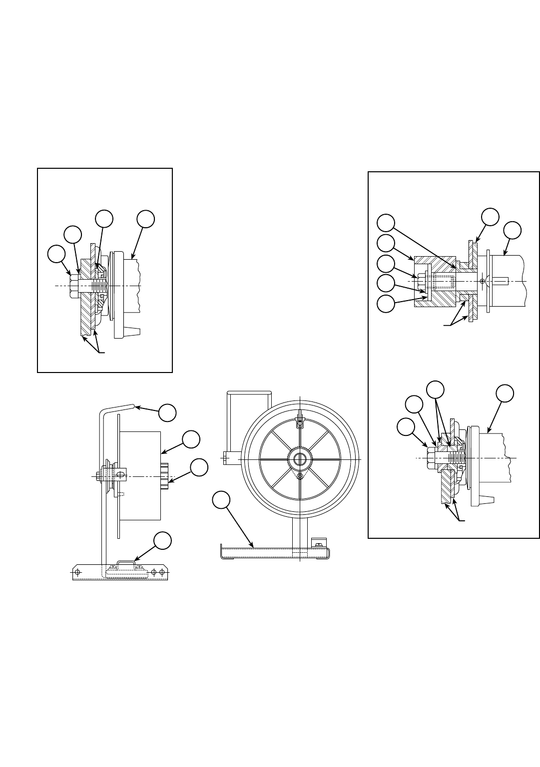
STAND ASSEMBLY FOR READI-REEL
(K377)
P-125-NP-125-N
Par t Number s Par t Numbers Part Number s Par t Number s
11-25-97
L6940
12-19-85G
13
3
1
10
CURRENT MOLDED
PLASTIC
9
8
14 2
WIRE WHEEL
SUPPORT
OBSOLETE ALUMINUM
SPINDLE ASSEMBLY
WIRE WHEEL
SUPPORT
9
8
52
WIRE WHEEL
SUPPORT
OBSOLETE MOLDED
PLASTIC SPINDLE ASSEMBLY
2
4
5
6
9
8
7
15

-
1 Wire Reel Support Assembly L6831-3
ø
1XXX
2 Wire Reel Shaft Assembly M14511 1 X • •
2 Spindle Assembly M14935 1 • X X
3 Readi-Reel Adapter K363-P 1 X X X
4 Insulating Washer S10773-52 1 X • •
5 Insulator Bushing T14816 1 X • •
5 Bushing T14844 1 • X •
6 Brake Disc Spacer T12967-1 1 X • •
7 Plainwasher S9262-14 1 X • •
8 Lockwasher E106A-15 1 X X X
9 Hex Head Screw 1/2-13 x 1.00 1 X • •
9 Hex Head Screw 1/2-13 x 1.75 1 • X X
10 Cable Clamp S16819 1 X X X
Thread Rolling Screw S9225-8 2 X X X
12 Retaining Collar S13871 1 X • •
13 Readi-Reel Decal T13086-44 1 X X X
14 Plainwasher S9262-14 1 • • X
15 Retaining Collar M14587-1 1 • • X
Optional - Not Illustrated
10# Wire Reel Spacer S18221 1 X X X
05-09-2002
ITEM DESCRIPTION PART NO. QTY. 123456789
P-125-N.1P-125-N.1
# Indicates a Change This Printing
Sub Ass embl y I l l ust r at i on Sub Assembl y I l l ust r at i on Sub Assembl y I l l ust r at i on Sub Assembl y I l l ust r at i on
For Obsolete Molded Plastic Spindle Assembly Use Column 1.
For Obsolete Aluminum Spindle Assembly Use Column 2.
For Current Molded Plastic Assembly Use Column 3.
#
øThis part is obsolete and no longer available.
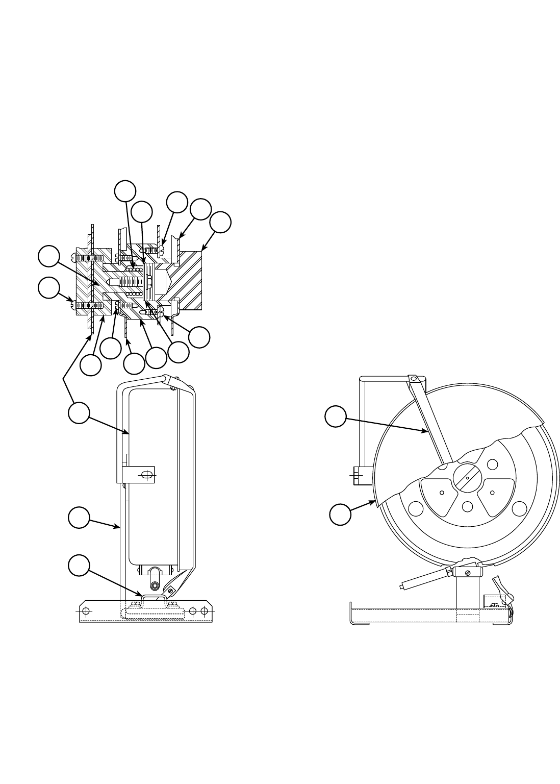
STAND ASSEMBLY FOR 14 POUND REEL
(K378)
P-125-OP-125-O
Par t Number s Par t Numbers Part Number s Par t Number s
1-28-2002
9
2
1
22
12 13
14
10
3
4
5
8
76
24
11
20
21

1 Wire Reel Support Assembly L6831-3
ø
1X
2 Wire Reel Housing, Includes: S17069-2 1 X
Housing M11940 1 X
Wire Sheath T14800 1 X
Wire Sheath Insulating Block S17068 1 X
Support Washer S15094 1 X
3 Axle S13954 1 X
4 Round Head Screw #10-24 x .875 4 X
Lockwasher E106A-1 4 X
5 Washer T13984 1 X
6 Axle Housing S13953 1 X
7 Wire Reel Cover (Back) M11574-2 2 X
8 Self Tapping Screw S8025-22 4 X
9 Spring T11862-8 1 X
10 Plainwasher S9262-45 1 X
11 Insulating Washer S10773-49 1 X
12 Hex Head Screw 5/16-18 x .75 1 X
Lockwasher E106A-3 1 X
Plainwasher S9262-61 1 X
13 Wire Reel Cover (Front) M11574-2 1 X
14 Axle Nut S13956 1 X
20 Housing Cover M11578 1 X
Decal S118932 1 X
21 Cover Retaining Strap Assembly S15891 1 X
22 Cable Clamp S16819 1 X
Thread Cutting Screw S9225-8 2 X
23 Coil Support Disc S17060 1 X
24 Thread Cutting Screw S9225-30 2 X
05-09-2002
Use only the parts marked “X” in the column under the
heading number called for in the model index page.
ITEM DESCRIPTION PART NO. QTY. 123456789
P-125-O.1P-125-O.1
# Indicates a Change This Printing
Sub Ass embl y I l l ust r at i on Sub Assembl y I l l ust r at i on Sub Assembl y I l l ust r at i on Sub Assembl y I l l ust r at i on
#
øThis part is obsolete and no longer available.


LN-6 Power Input Cable Assembly, Includes: K164* 1
Control Cable Assembly, Includes: L4700-B*
ø
1
Amphenol Connector (Female) S12020-11 1
Amphenol Connector (Male) S12020-12 1
Amphenol Connector Clamp S12024-2 2
Electrode Cable Assembly L4700-C* 1
LN-8 & LN-9 Power Input Assembly, Includes: K196* 1
Control Cable Assembly, Includes: L5027-B* 1
Amphenol Connector (Female) S12020-8 1
Amphenol Connector (Male) S12024-2 1
Electrode Cable Assembly L5027-C* 1
LN-6NE & LN-6SE Extension Cable Assembly, Includes:
M11518** 1
Control Cable Assembly, Includes: M11517** 1
Amphenol Connector (Female) S12020-11 1
Amphenol Connector (Male) S12023-3 1
Amphenol Connector Clamp S12024-2 2
Conductor Cable Assembly L4702** 1
LN-8NE, 8SE, 9NE & 9SE Extension Cable
Assembly Includes: M12220** 1
Control Cable Assembly, Includes: M12219** 1
Amphenol Connector (Female) S12020-8 1
Amphenol Connector (Male) S12023-2 1
Amphenol Connector Clamp S12024-2 2
Conductor Cable Assembly L4702** 1
Flux Hose, 22-1/2 Ft.
(Reqʼd. For All Submerged Arc Machines) T10642-82
ø1
Flux Hose, 45 Ft.
(Reqʼd. For All Submerged Arc Machines) T10642-83 1
Electrode Cable, 22-1/2 Ft.
(Reqʼd. On All Machines Above 450 Amps) M5906-106 1
Electrode Cable, 45 Ft.
(Reqʼd. On All Machines Above 450 Amps) M5906-104 1
* Specify Cable Length and Maximum Current
Draw Thru Cable.
** Specify “ 22-1/2 Ft.” or “ 45 Ft.” as appropriate.
07-26-2005
ITEM DESCRIPTION PART NO. QTY. 123456789
P-107-MP-107-M
# Indicates a Change This Printing
INPUT CABLE AND EXTENSION CABLE ASSEMBLIES
øThis part is obsolete and no longer available.
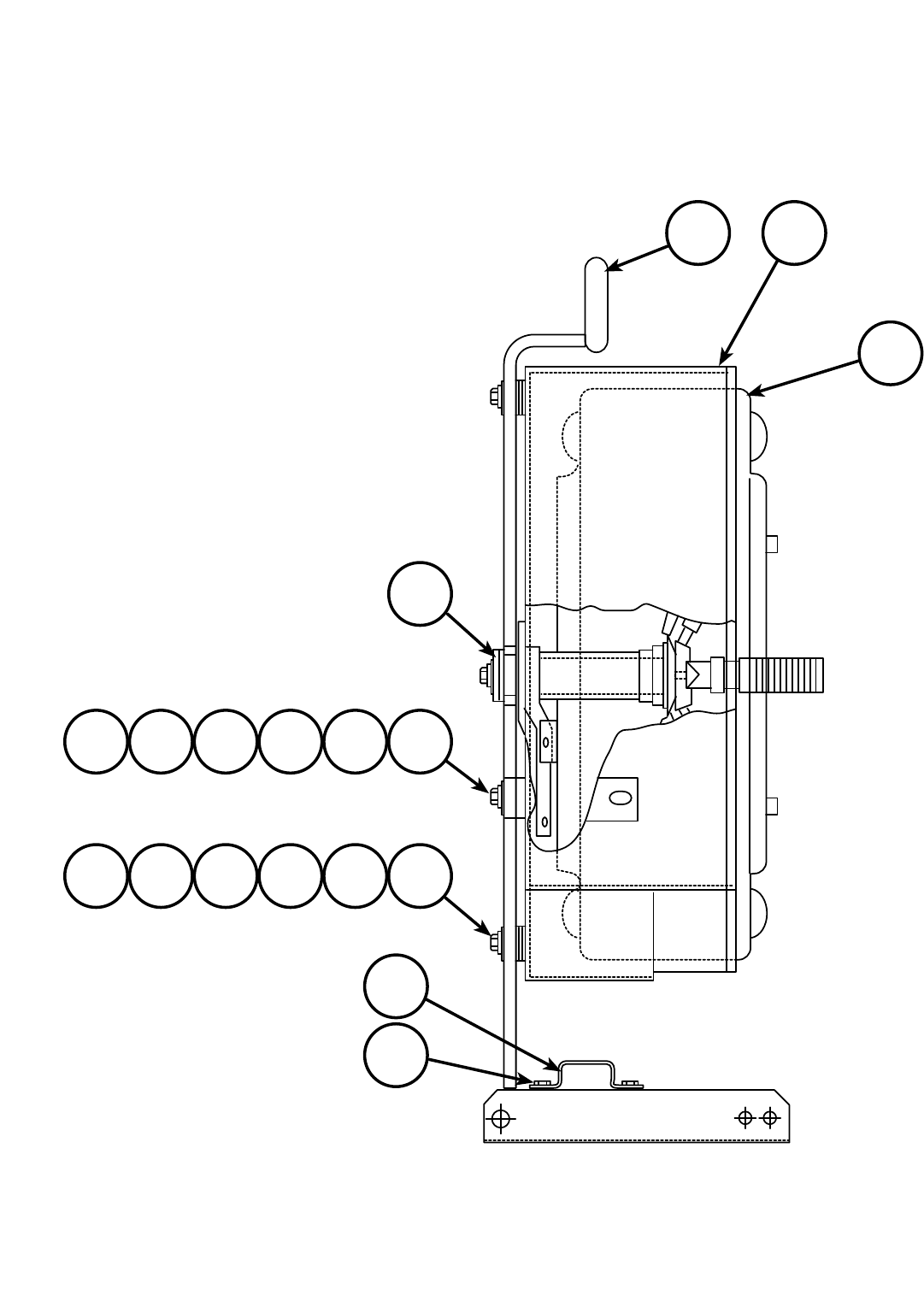
50 AND 60# WIRE REEL SUPPORT
P-107-OP-107-O
Par t Number s Par t Numbers Part Number s Par t Number s
07-26-2005
3 2
1
10
13
87654
987654
11
12
L4699

LN-6, LN-7, LN-8 & LN-9 Wire Reel Support
Assembly, Includes: L4699-2 1 X X • • X •
LN-7 Wire Reel Support Assembly, Includes: L4959-2 1 • • X • • •
LN-7 Wire Reel Support Assembly, Includes: L4959-3 1 • • • • • X
1 Wire Reel L4604 1 X X X • X X
1 Wire Reel S18179 1 • • • • • X
2
Wire Reel Housing (For LN-7, K376 Reel, See Note 1)
S13858 1 X X • • X •
3 Reel Support L4680 1 X X X • X X
4 Plain Washer S9262-23 6 X X • • X •
5 Lock Washer E106A-2 3 X X • • X •
6 1/4-20 HN CF000017 3 X X • • X •
7 1/4-20 x 1.50 HHCS CF000141 3 X X • • X •
8 Insulating Washer S10773-41 12 X X • • X •
9 Insulating Tube T7028-90 1 X X • • X •
10 Reel Mounting Shaft Assembly See P-107-P 1 X X X • X •
10 Reel Mounting Shaft Assembly Order K162-H 1 • • • • • X
11 Cable Clamp S16819 1 X X X • X X
12 Thread Cutting Screw S9225-8 2 X X X • X X
13 Insulating Tube T7028-180 2 X X • • X •
Optional Door Assembly, Includes: M11514 Note 11 XXX•XX
Door and Hinge Welded Assembly L4692 1 X X X • X X
Catch T12652 1 X X X • X X
Sealing Panel S14049 1 X X X • X X
Sealing Panel Mounting Plate S14067 2 X X X • X X
LN-XNE & LN-XSE Fully Wire Reel Support
Assembly, Includes all Above plus: L4745
ø
1 •X•••X
LN-22 Fully Enclosed Wire Reel Support Assembly,
Includes all above plus: L4745-2 1 • • • • X •
Hand Crank Assembly See P-107-R 1 • X • • • X
Wire Feed Unit Handle S13863 1 • X • • • X
LN-XNE Lightweight Wire Reel Support Assembly,
Includes: L5369-2
ø
1•••X••
Wire Reel L4604 1 • • • X • •
Hand Crank Assembly See P-107-R 1 • • • X • •
Cage Type Wire Reel Support L5368 1 • • • X • •
Wire Feed Unit Handle S13863 1 • • • X • •
Reel Mounting Shaft Assembly (For 2” I.D. Spools) Order K162 1 • • • X • •
Reel Mounting Shaft Assembly (Standard) M12460 1 • • • X • •
08-25-2009
For LN-6N, 6S, 7, 8N, 8S, 9HN and 9S (K303 Wire Reel Open Shroud), use Column 1. For Enclosed LN-6NE, 8NE, 9NE
and 9SE, use Column 2. For LN-7 (K376 Wire Reel, No Shroud), use Column 3. For lightweight LN-6NE, 6SE, 8NE, 9NE
and 9SE, use Column 4. For LN-22 use Column 5. For K445 use Column 6.
ITEM DESCRIPTION PART NO. QTY. 123456789
P-107-O.1P-107-O.1
# Indicates a Change This Printing
Sub Ass embl y I l l ust r at i on Sub Assembl y I l l ust r at i on Sub Assembl y I l l ust r at i on Sub Assembl y I l l ust r at i on
øThis part is obsolete and no longer available.
#
#
NOTE 1: To equip an LN-7 with a wire reel cover kit order S14543. Includes items 2, 4 through 9 and 13.
For LN-7, K376 or K445 Reel, S14543 must also be installed when a K1898-1 door is to be
installed.
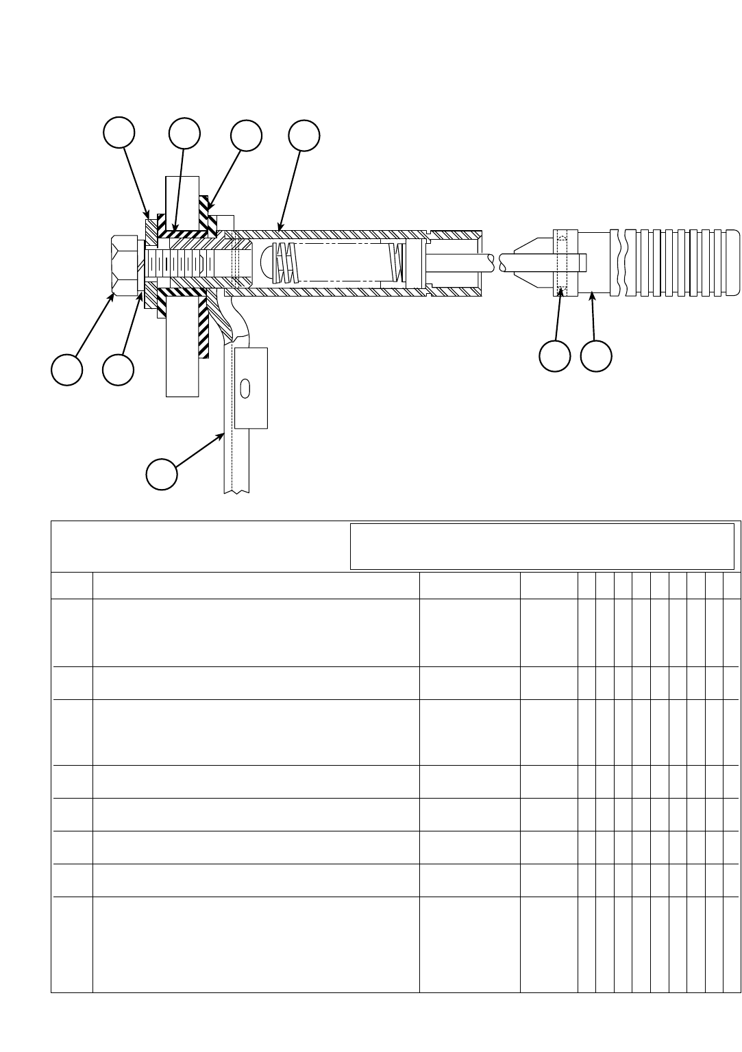
Reel Mounting Shaft Assembly, Includes: M12460 1 X • •
Reel Mounting Shaft Assembly, Includes: M12908 1 • X •
Reel Mounting Shaft Assembly, Includes: M12460-1 1 • • X
1 Hex Head Bolt 1/2-13 x 1.00 1 X X X
2 Lock Washer E106A-15 1 X X X
4 Brake Assembly, Includes: S14882* 1 X • •
4 Brake Assembly, Includes: S14882-1 1 • X X
Brake T13519 1 X X X
Cotter Pin S10750-19 1 X X X
5 Plain Washer (1.38 O.D.) S9262-14 1 X X X
5 Plain Washer (1.50 O.D.) S9262-119 1 • X •
7 Insulator Bushing T14816 1 X • X
8 Insulating Washer S10773-52 1 X • X
9 Wire Reel Shaft Assembly S16253 1 X • X
9 Wire Reel Shaft Assembly S15492 1 • X •
10 Roll Pin T9967-9 1 X X X
11 Pull Knob S11038 1 X X X
* LN-6 and LN-7 welders built before November 1972
did not have the adjustable brake (Item 4). If a shaft
or fixed brake assembly is needed, order the
M12460 Assembly.
4-19-2000
For All LN-6, LN-7, LN-8S, 8N, 8SE, LN-9S, 9N, 9SE, 9NE, 9NH and
LN-22, use Column 1. For LN-8F, LN-9F and LN-9FH, use Column 2.
For SP-200, use Column 3.
ITEM DESCRIPTION PART NO. QTY. 123456789
P-107-PP-107-P
# Indicates a Change This Printing
WIRE REEL SHAFT
Par t Number s Par t Number s Par t Number s Par t Number s
7
59
1110
4
21
8
M12460
#
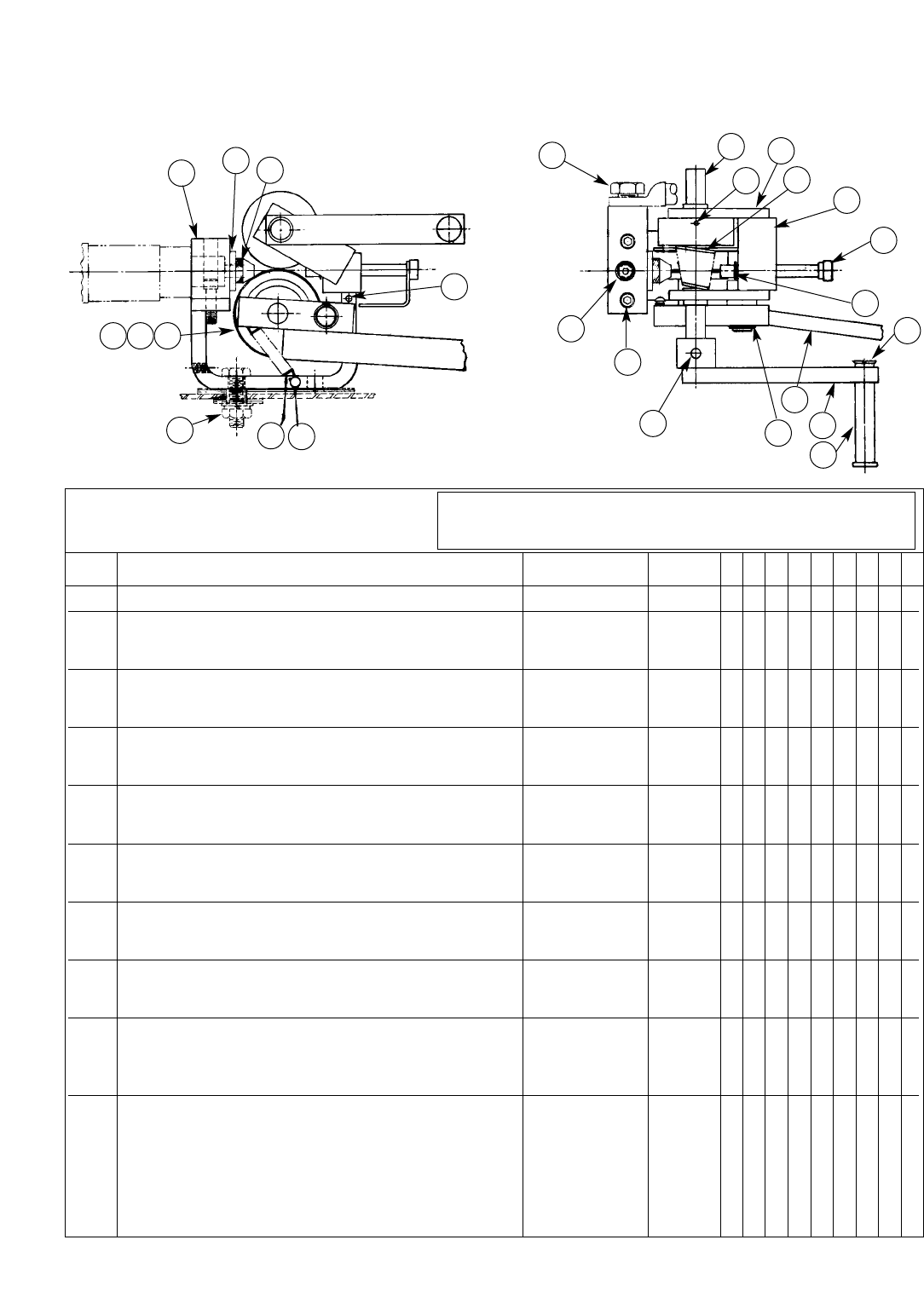
HAND CRANK ASSEMBLY
LN-6, LN-7, LN-8 and LN-9
P-107-RP-107-R
Par t Number s Par t Number s Par t Number s Par t Number s
01-30-2003
Hand Crank Assembly, Includes: L4703
ø
1
1 Plain Washer S9262-120 1
2 Hex head Screw 3/8-16 x .50 1
3 Bracket Assembly M10965
ø
1
4 Lever Arm Stop pin T9967-4 1
5 Drive Screw S8025-7 2
6 Tension Spring T11514 1
7 Guide Tube S13686 1
8 Spacer Washer S9262-56 1
9 Conductor Block S13687 1
10 Hex head Screw 1/2-13 x .75 1
11 Shaft T12650-1 1
12 Roll Pin T9967-31 1
13 Drive Roll S12805 1
14 Conical Spring T12648 1
15 Idle Roll (1/16 thru .120) T12556-4 1
17 Incoming Guide Tube T12654 1
18 Retaining Ring S9776-1 1
19 Flat Head Screw 5/16-18 x 1.25 1
20 Handle S13397 1
21 Crank Arm Assembly S13392 1
22 Lever Arm Assembly S13404 1
23 Retaining Ring S9776-3 1
24 Fiber Pin T8433 1
25 Socket Head Cap Screw T9447-10
ø
2
26 Set Screw S11604-11 1
27 Hex Head Screw 3/8-16 x 1.25 2
Insulating Tube T7305-4 2
Insulating Washer S10773-19 2
Plain Washer S9262-120 2
Lock Washer E106A-4 2
Hex Nut 3/8-16 2
Insulating Pad T8477-12 1
For All LN-6, LN-7, LN-8S, 8N, 8SE, LN-9S, 9N, 9SE, 9NE, 9NH and
LN-22, use Column 1. For LN-8F, LN-9F and LN-9FH, use Column 2.
For SP-200, use Column 3.
ITEM DESCRIPTION PART NO. QTY. 123456789
# Indicates a Change This Printing
L4703
987
1521
27 65
4
10 11
12
13
14
3
17
18
19
20
21
22
23
24
25
26
øThis part is obsolete and no longer available.
#
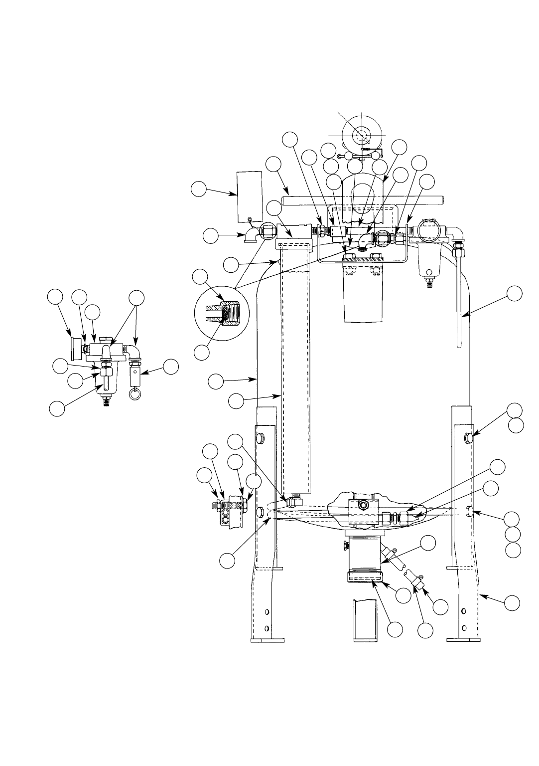
FLUX TANK
(LN-6, LN-7, LN-8 and LN-9)
P-107-SP-107-S
Par t Number s Par t Numbers Part Number s Par t Number s
3-15-82
L4695-4
9-19-80J
30
11
23
24
25
21
22
N.E.
18
48
26
6
27
17
14
1
29
28
2
11
12
13
3
9
10 15 8
40
11
22
5
6
7
4
21
16
6
35
36
16
6
7
20
37
38
34
33
32

Flux Tank Assembly, Includes: K320 1 X • •
Flux Tank Assembly, Includes: L4695-4 1 • X •
Flux Tank Assembly, Includes: L4695-2 1 • • X
1 Flux Tank G1204 1 X • •
1 Flux Tank G1204-1 1 • X X
2 Decal T11182 1 X X X
3 Tank Cover S11461 1 X X X
4 Instrument Mounting Bracket S12741 1 X X X
5 Hex Head Screw 1/2-13 x 1.25 2 X X X
6 Lock Washer E106A-5 8 X X X
7 Hex Nut 1/2-13 4 or 5 X X X
8 Pipe Nipple T9959-11 1 X X X
9 Check Valve T11130 1 X • •
9 Check Valve T14410 1 • X X
10 Pipe Nipple T9959-7 1 X • •
10 Pipe Coupling T12390-1 1 • X X
11 Street Elbow T9958-2 4 X X X
12 Caution Tag T11416 1 X X X
13 Air Line Filter S11060 1 X X X
14 Water Separator M8985-1
ø
1XXX
15 Strainer S16628-1 1 X X X
16 Hex Head Screw 1/2-13 x .75 5 X X X
17 Compression Elbow S7531 1 X X X
18
Bleeder Line (For LN-4 or LN-5, Also Order Items 35 & 36)
T12995 1 X X X
20 Flux Tank support S12737 3 X X X
21 Copper Line (For LN-4 or LN-5, Order S4893-65)
ø
S4893-61 1 X • •
21 Copper Line S4893-66 1 • X X
22 Male Connector T11167 2 X X X
23 Pressure Regulator S11028 1 X X X
24 Reducing Bushing T9948 1 X X X
25 Pressure Gauge S11395 1 X X X
26 Clamp S12740 1 X X X
27 Hex Head Screw 1/2-13 x 2.75 1 X X X
28 Adaptor T11248 2 X X X
29 Screen Cup T11249 2 X X X
30 Safety Valve T11394 1 X X X
31 Street Tee T11393 1 X • •
32 Cap Gasket T11225-1 1 X X X
33 Outlet Tube Cap S11155 1 X X X
34 Outlet Assembly S12739 1 X X X
35 Union T12754 1 X X X
36 Flared Copper Tube T12755 1 X X X
37 Flux Hose T10642-81 1 X • •
37 Flux Hose (8 Ft. Boom) T10642-80
ø
1••X
37 Flux Hose (11Ft. Boom) T10642-79 1 • • X
37 Flux Hose (14 Ft. Boom) T10642-77 1 • • X
38 Hose Clamp (Tank End) S10888-27 2 X X X
40 Lift Bail Assembly M11483 1 X X •
Flux Funnel - Not Illustrated S11062 1 X X X
Air Line Connector - Not Illustrated T14390-2 1 • • X
12-20-2001
Use Column 1 for Flux Tanks with Safety Valve on Outlet Assembly.
Use Column 2 for Flux Tanks with Safety Valve on Pressure Regulator.
Use Column 3 for Flux Tanks used on Welding Station.
tITEM DESCRIPTION PART NO. QTY. 123456789
P-107-S.1P-107-S.1
# Indicates a Change This Printing
Sub Ass embl y I l l ust r at i on Sub Assembl y I l l ust r at i on Sub Assembl y I l l ust r at i on Sub Assembl y I l l ust r at i on
#
#
øThis part is obsolete and no longer available.
#
#
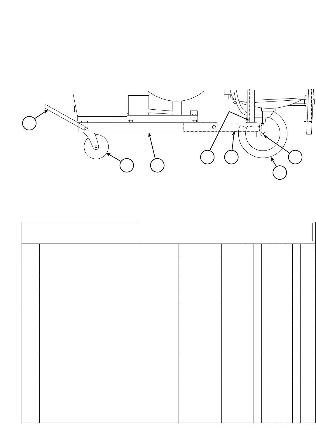
Undercarriage, Includes: K163 1 X •
Undercarriage, Includes:
(Standard Equip.)
1•X
2 Handle M10469-1 1 X X
3 Casters S11124 2 X X
4 Base, Platform Type (Discontinued) L4688 1 X X
4 Base, Open Frame Type L5239 1 X X
6 Wheels S13127 2 X X
7 Axle M10470 1 X X
12 Flux Tank Support S12737 3 • X
10-22-97
For optional K163 use parts marked “X” in Column 1.
For LN-6S, 6SE, 8S, 8SE, 9S, and parts marked “X” in Column 2.
P-107-TP-107-T
# Indicates a Change This Printing
UNDERCARRIAGE: K163
Standard with LN-6S, LN-6SE, LN-8S, LN-8SE, LN-9S and LN-9SE
Par t Number s Par t Number s Par t Number s Par t Number s
#
43
2
912
6
7
ITEM DESCRIPTION PART NO. QTY. 123456789

NOTES
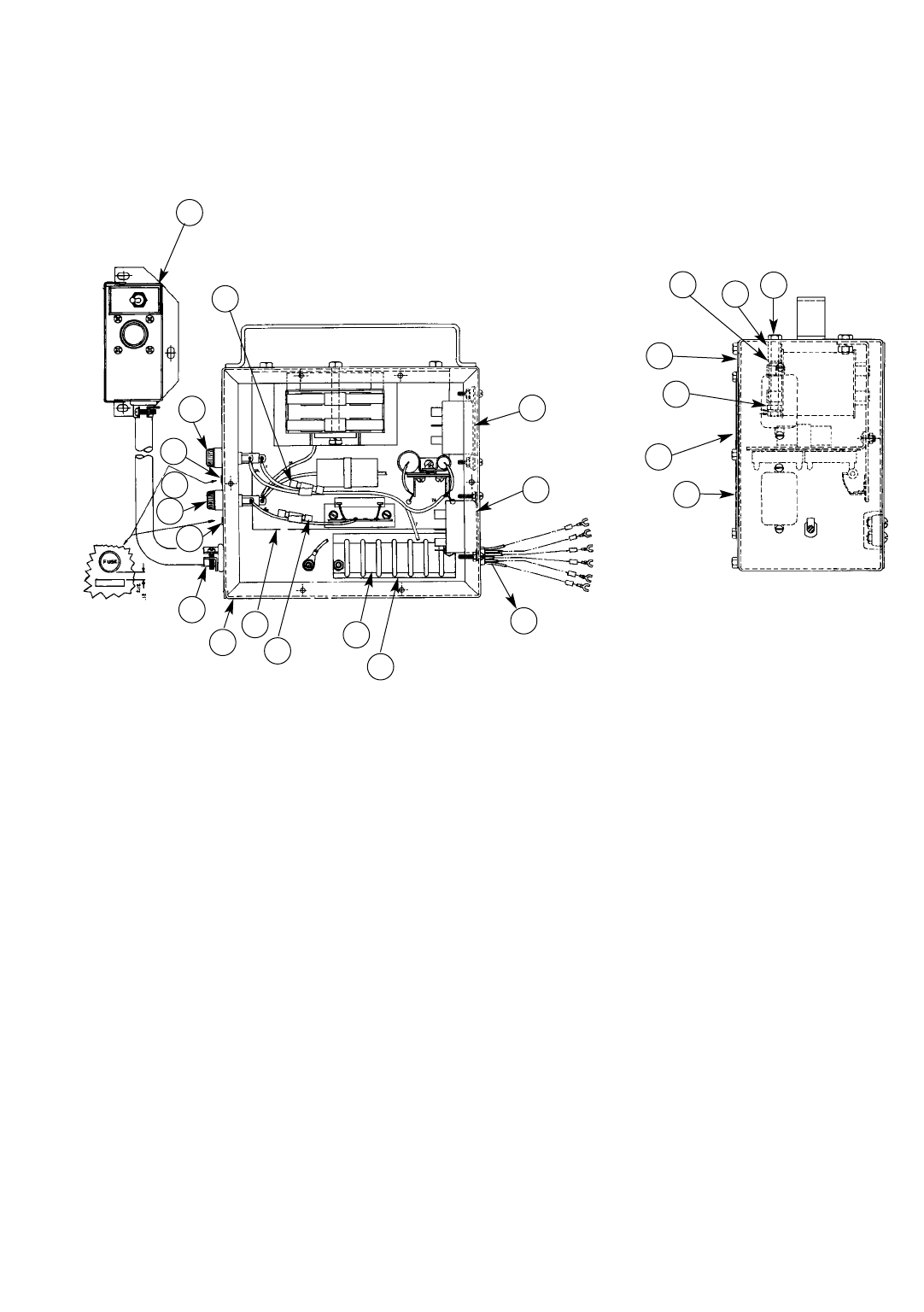
MECHANIZED TRAVEL POWER PACK: K161
P-107-V.aP-107-V.a
Par t Number s Par t Numbers Part Number s Par t Number s
05-10-2005
G1429
10-23-81N
9
33
14
34
23
14
13
10
1
2
18 3
6
8
7
30
26
25
24
18
27
16
28

Mechanized Travel Power Pack, Includes: K161* 1 X X
1 Case Welded Assembly M9734 1 X X
2 Mag-Amp Assembly, Includes: L3524-1 1 X X
Core and Coil Assembly M9017 1 X X
Resistor S10404-15 1 X X
Insulation T11134-1 1 X X
Terminal Strip T10707 1 X X
Condenser T11577-37 1 X X
Rectifier Assembly S13707 1 X X
5 Terminal Strip S8542 1 X X
6 Number Plate T10726-60 1 X X
7 Relay S22182 1 X X
8 Lead Grommet T9274-1 1 X •
8 Lead Grommet T9274-2 1 • X
9 Adapter Box Assembly, Includes: M11617* 1 X X
Amphenol Connector (Next to Toggle Switch) S12021-3 1 X X
Toggle Switch T13083 1 X X
Amphenol Connector (Opposite Side of Box
from Switch) S12020-6 1 X X
10 Connector T9639-2 1 X X
13 Fuse (1/8 Amp) T10728-9 2 X X
14 Fuse Holder S10433 2 X X
16 Nameplate M9730 1 X X
18 Front Panel S11344 1 X X
23 Fuse Identification Sticker T12607-9 1 X X
24 Insulation T11472-5 1 X X
25 Spacer S10040-33 1 X X
26 Hex Head Screw 1/4-20x3.00 1 X X
27 Spacer S10040-34 1 X X
28 Wiring Diagram S13868 1 X •
28 Wiring Diagram M20116 1 • X
30 Relay S15122-10 1 • X
33 Fuse T10728-10 2 X X
34 Fuse Identification Sticker T12607-10 1 X X
*Specify Cable Length
05-10-2005
Use Parts Marked “X” in Column 1 for Code 6801.
Use Parts Marked “X” in Column 2 for Code 7627.
ITEM DESCRIPTION PART NO. QTY. 123456789
P-107-V.bP-107-V.b
# Indicates a Change This Printing
#
Sub Ass embl y I l l ust r at i on Sub Assembl y I l l ust r at i on Sub Assembl y I l l ust r at i on Sub Assembl y I l l ust r at i on
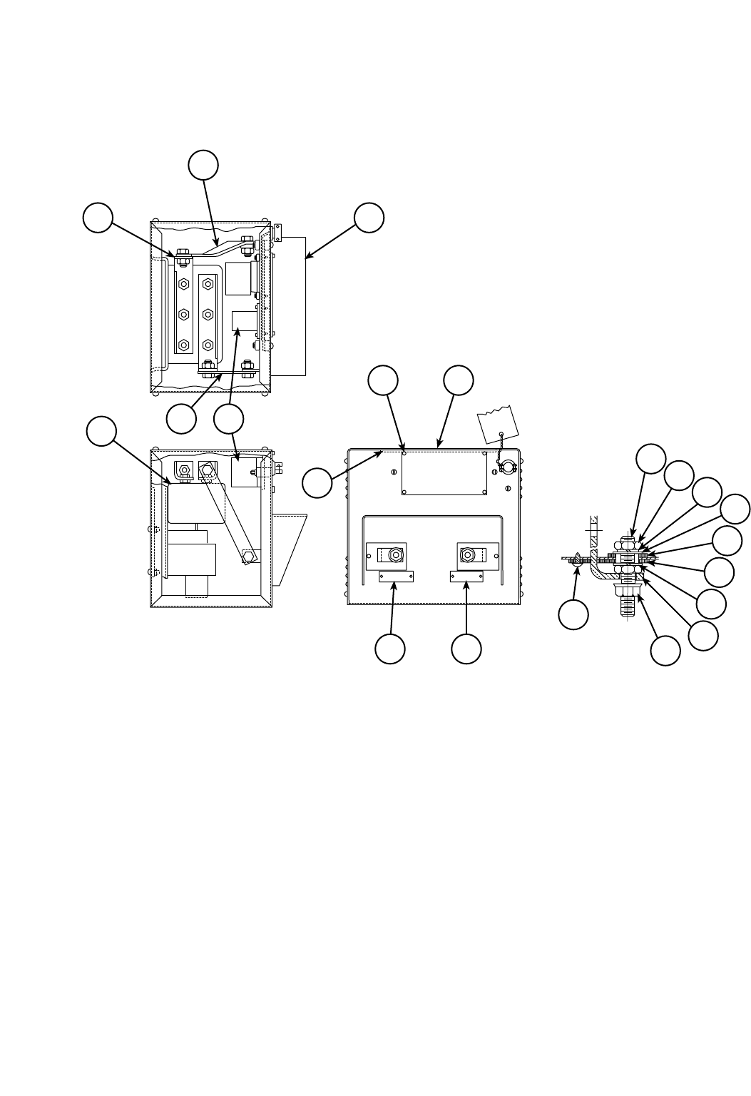
CONTACTOR KIT: K240
P-107-W.2.aP-107-W.2.a
2
3 1
12 413
14
6 7
11 10
25
24
23
22
21
20
19
18
17
16
Par t Number s Par t Numbers Part Number s Par t Number s
6-20-86
L5360
6-20-86S

1 Case M12799 1
2 “Power Source” Lead S15017-12 1
3 Contactor Jumper S13472-3 2
4 “Auto Equipment” Lead S15017-11 1
5 Warning Decal T13470 1
6 Wraparound L4397-1
ø
1
7 Nameplate M12802 1
10 “Power Source” Marker T10743 1
10 Rivet T8973 2
11 “Auto Equipment” Marker T12256 1
11 Rivet T8973 2
12 S67 Contactor (Early Machines) L4300-35 1
L4300-35 Contactor Parts See P-28-H
12 S78 L6200-4 1
L6200-4 Contactor Parts See P-28-J
13 Relay S10834-1 1
13 Rubber Chassis Mount T10325-1 4
14 Printed Wiring Diagram S15371 1
16 Stud T6931-11 2
17 Hex Jam Nut 1/2-13 4
18 Lock Washer E106A-5 2
19 Flat Washer S9262-1 4
20 Insulating Washer S10773-9 2
21 Insulating Panel T14373 2
22 Insulating Tube T14374 2
23 Connecting Strap T8141 2
24 Flange Nut T3960 2
25 Self Tapping Screw S8025-65 2
06-12-2001
ITEM DESCRIPTION PART NO. QTY. 123456789
P-107-W.2.bP-107-W.2.b
# Indicates a Change This Printing
Sub Ass embl y I l l ust r at i on Sub Assembl y I l l ust r at i on Sub Assembl y I l l ust r at i on Sub Assembl y I l l ust r at i on
#
øThis part is obsolete and no longer available.
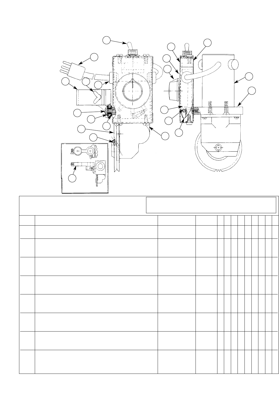
t
Gun Drive Unit Assembly, Includes: K110 1
1 Mounting Clamp M9108 1
2 Thumb Screw T9078-3 1
3 Control Cable and Plug S11837 1
5 Grommet T9274-1 2
6 Truss Head Screw 8-32x5/8 2
7 Insulator Bushing T11215-2 2
8 Drive Wheel M9122 1
9 Hollow Set Screw, Cup Point S11604-13 1
11 Resistor T12731-3 1
14 Reversing Switch T13111 1
15 Insulating Plate T11221 1
16 Control Box Back M9027-1 1
17 Control Box Front M9693 1
19 Dial Plate S11163 1
20 Knob T11157 1
21 Insulation T11228 1
22 Rheostat T10812-9 1
23 Gear Box assembly See P-107-Y 1
26 Motor S11162 1
27 Adapter Plate M9109 1
28 Mounting Clamp Extension M9142 1
05-10-2005
Use only the parts marked “X” in the column under the
heading number called for in the model index page.
ITEM DESCRIPTION PART NO. QTY. 123456789
P-107-XP-107-X
# Indicates a Change This Printing
MECHANIZED HAND TRAVEL UNIT: K110
Par t Number s Par t Number s Par t Number s Par t Number s
L3865
4-3-81E
27
26
16
14
17
19
20
22
11
21
23
28
9
815
7
6
2
15
3
METHOD OF MOUNTING EXTENSION
NOTE: FOR PROPER LEAD
CONNECTIONS SEE
WIRING DIAGRAM
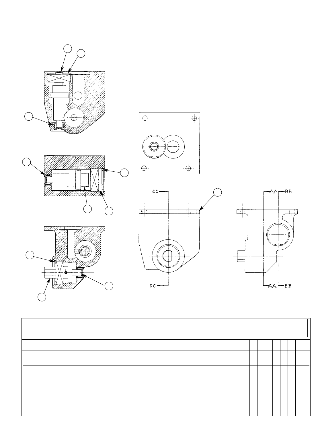
Gun Drive Gear Case Assembly, Includes: L3569 1
1 Gear Box L3568 1
2 Needle Bearing S10116-2 3
3 Retaining Ring S9776-9 3
4 Vertical Shaft Assembly S11160 1
5 Cross Shaft Assembly S11161 1
6 Shaft Cap T11226 1
7 Output Shaft Assembly S11159 1
9-69
Use only the parts marked “X” in the column under the
heading number called for in the model index page.
ITEM DESCRIPTION PART NO. QTY. 123456789
P-107-YP-107-Y
# Indicates a Change This Printing
GEAR BOX FOR K110
Par t Numbers Part Number s Par t Number s Par t Number s
43
2
2
3
6
5
1
2
3
7

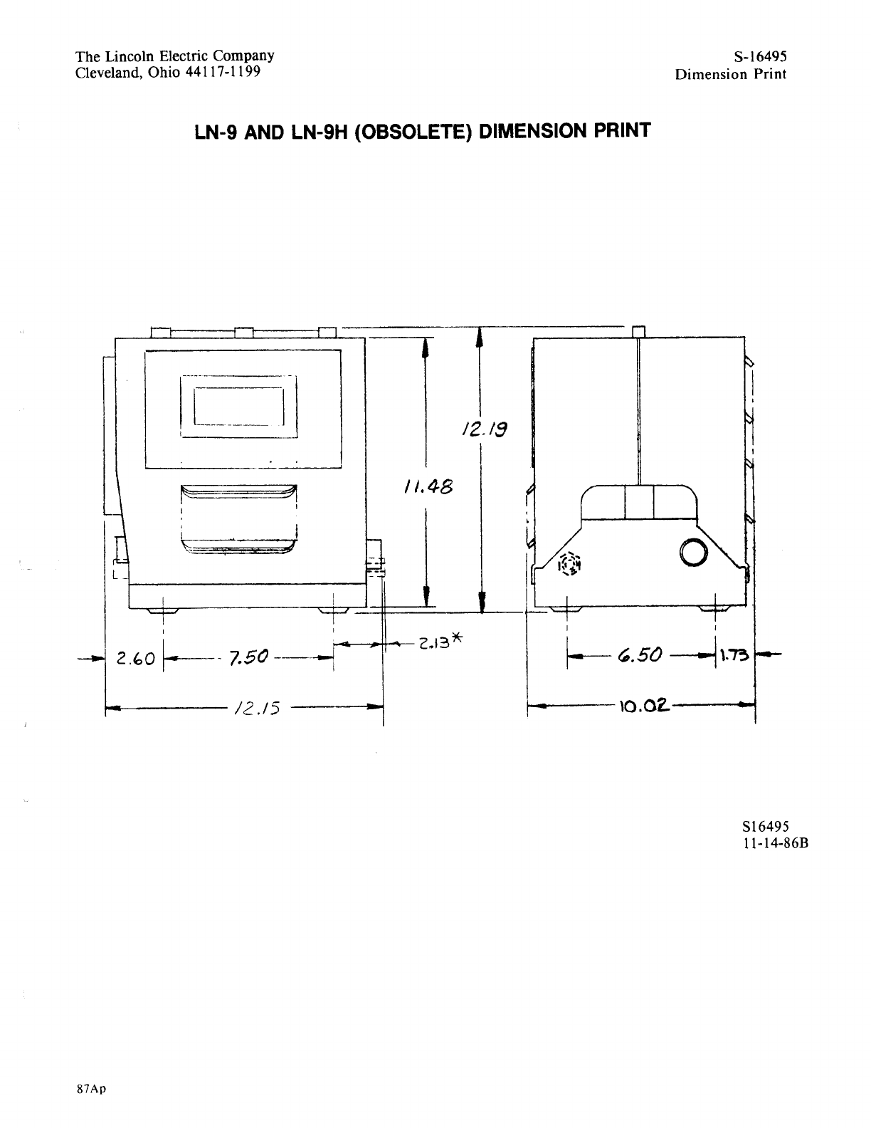
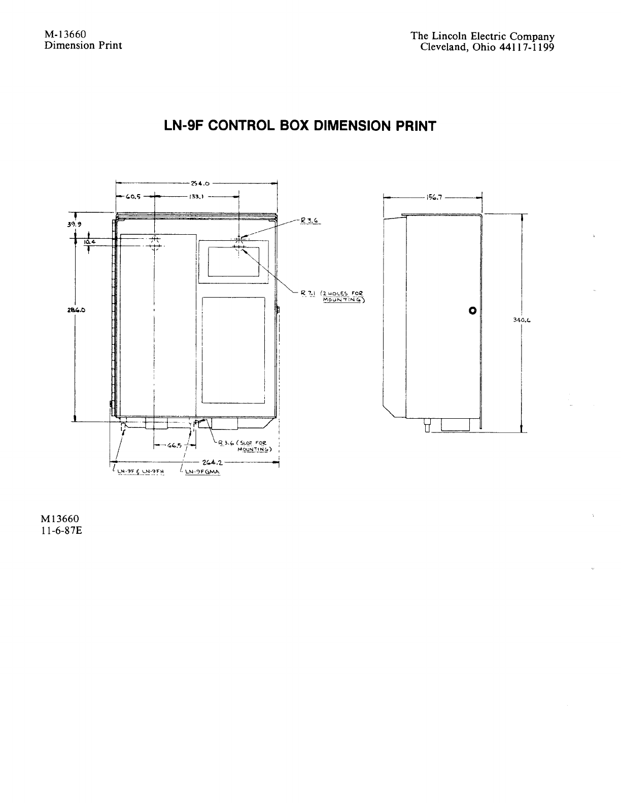
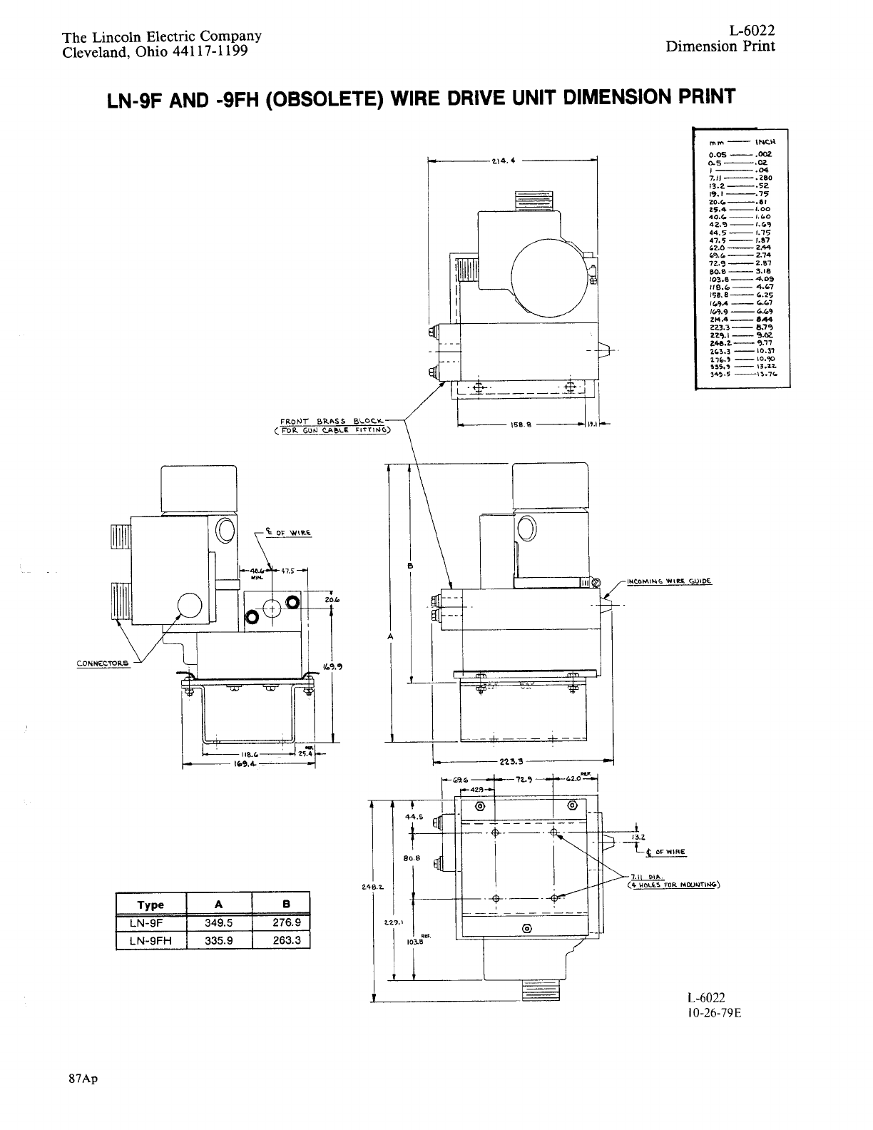
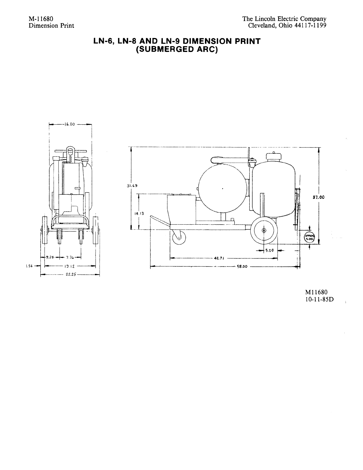
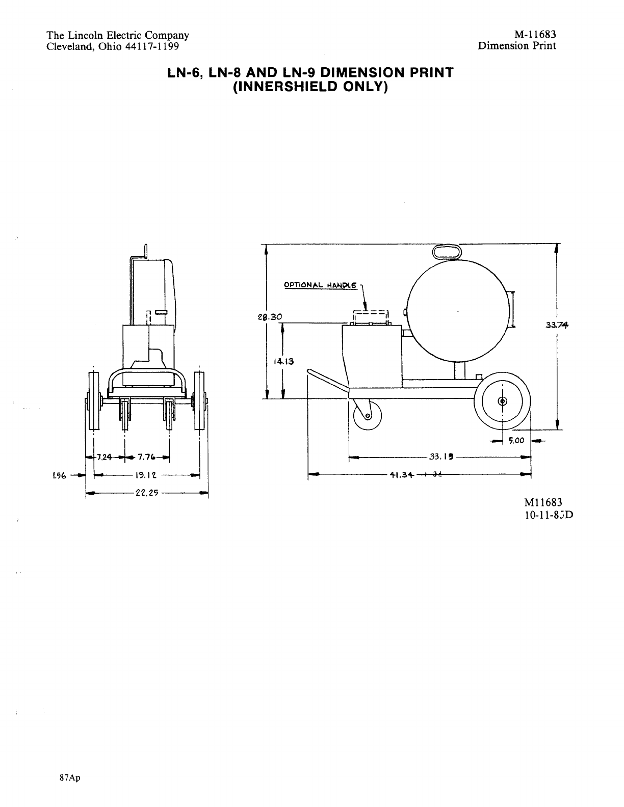
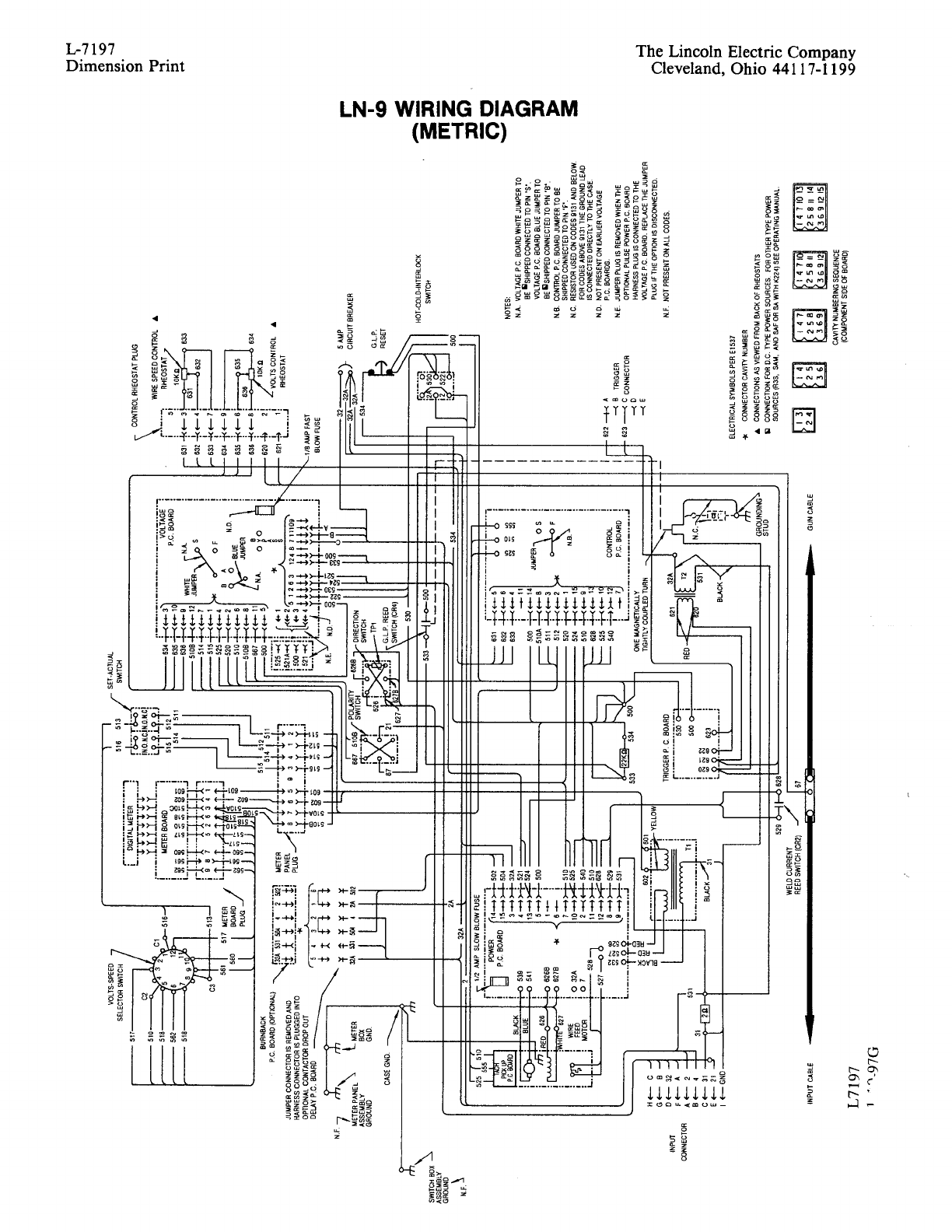
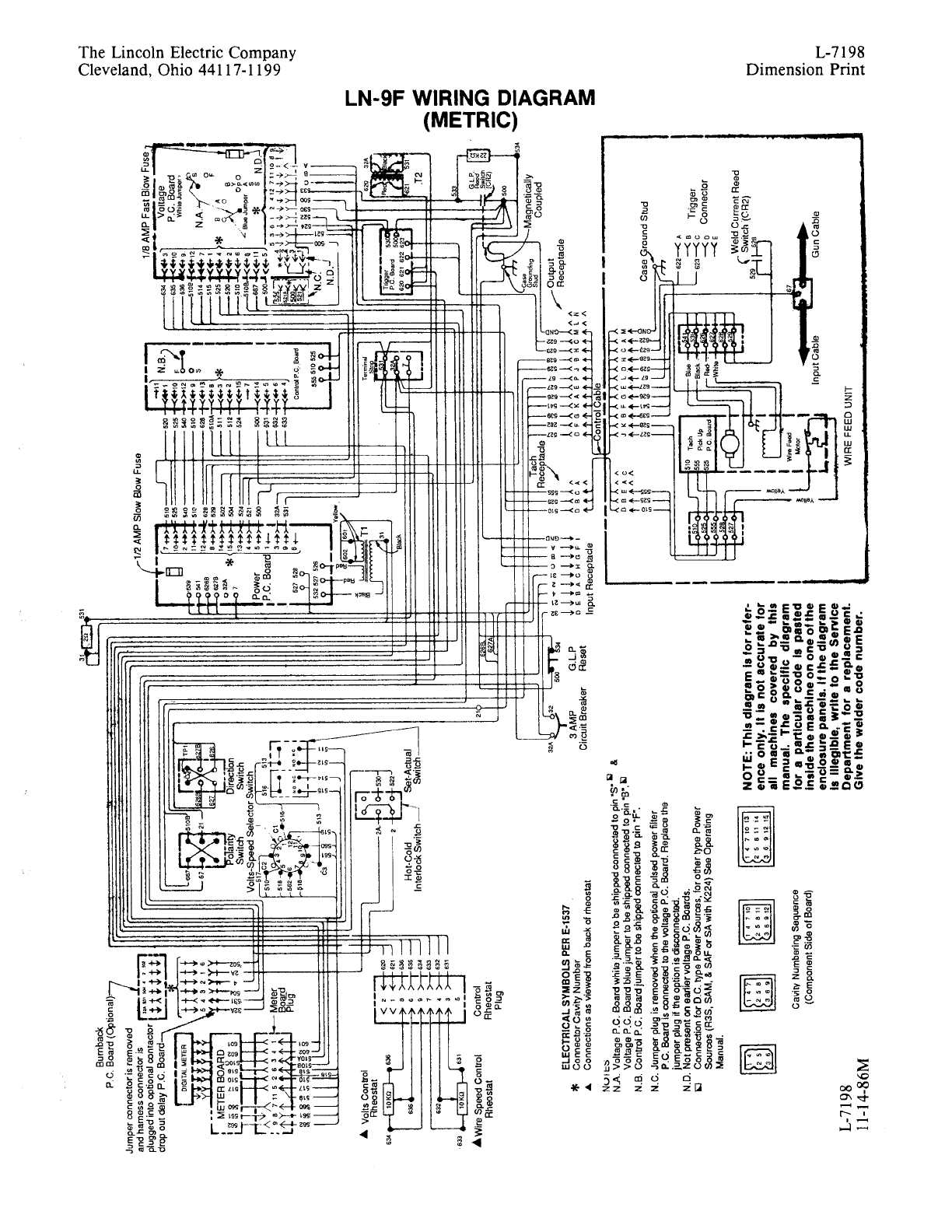
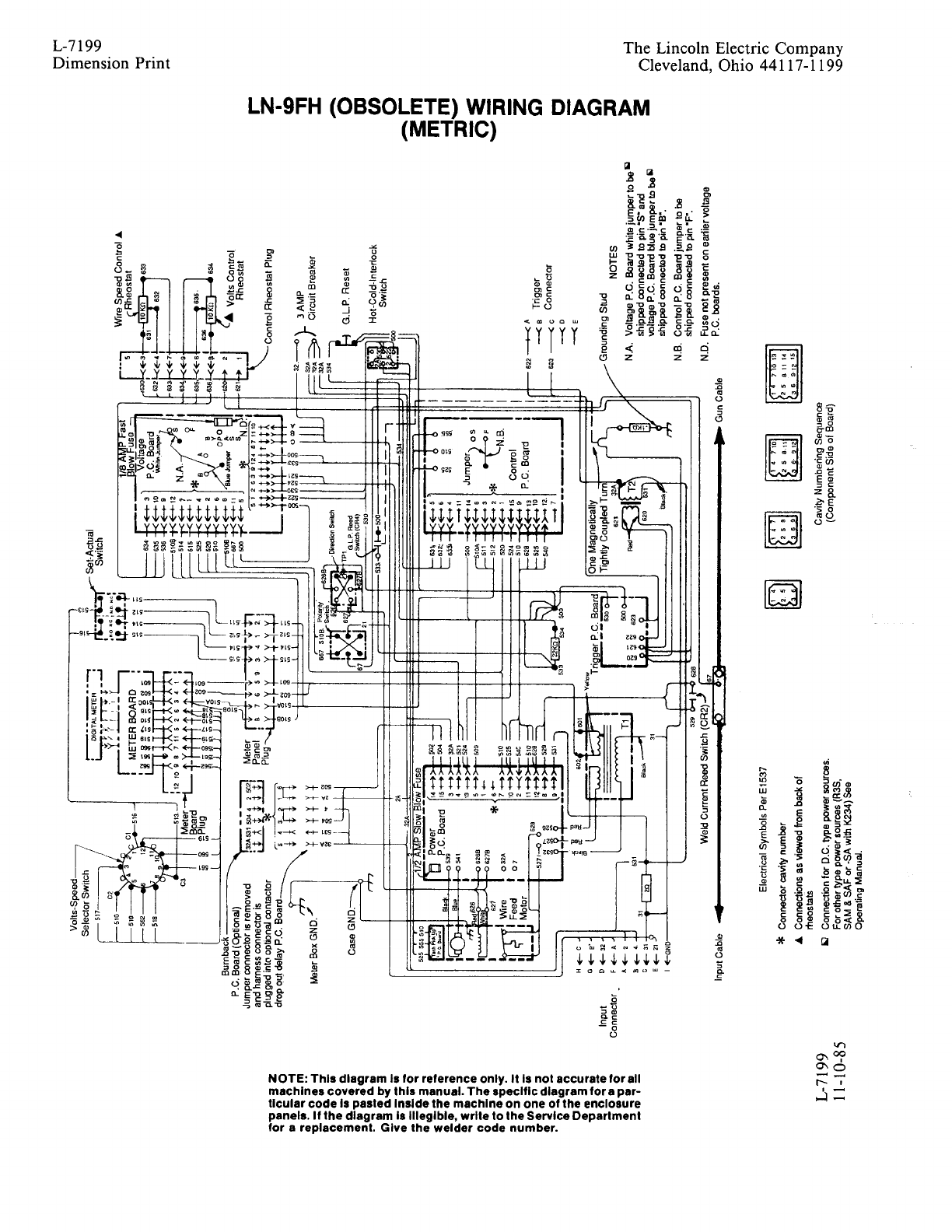
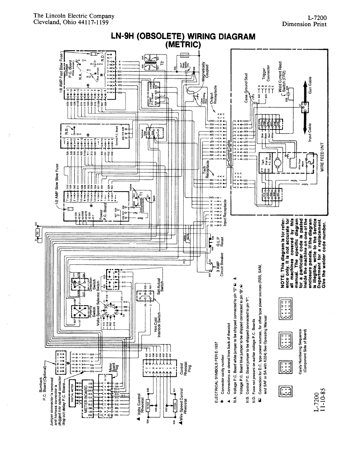
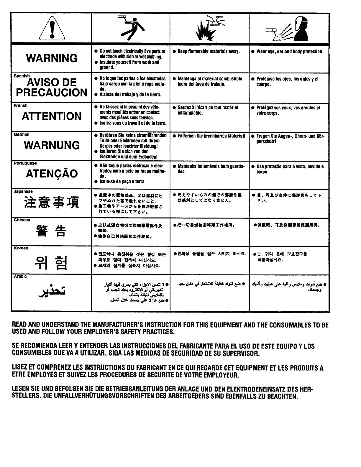
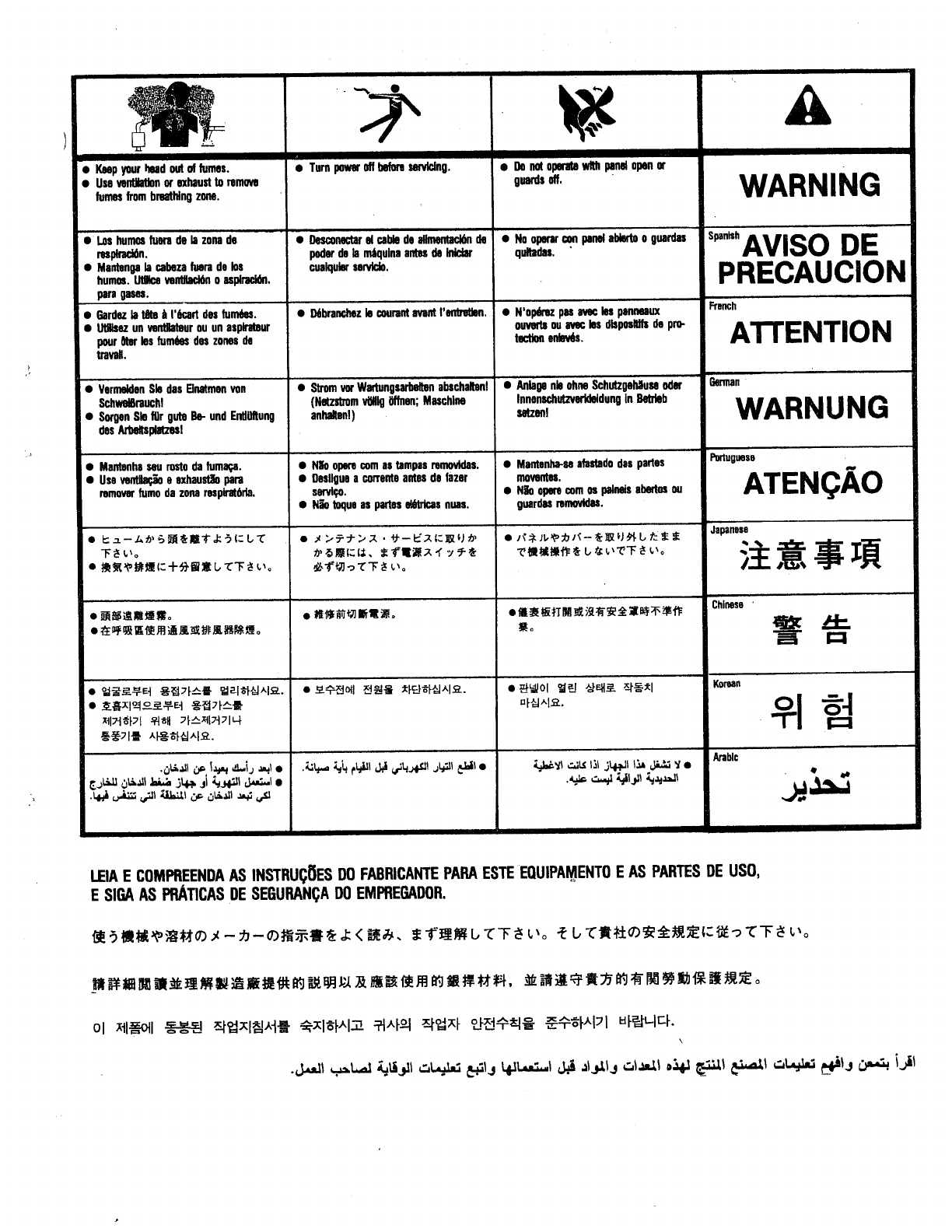

• World's Leader in Welding and Cutting Products •
• Sales and Service through Subsidiaries and Distributors Worldwide •
Cleveland, Ohio 44117-1199 U.S.A. TEL: 216.481.8100 FAX: 216.486.1751 WEB SITE: www.lincolnelectric.com
