Lincoln Electric Power Wave Svm135 B Users Manual Svm135b
SVM135-B to the manual b7a4e6b5-c0b9-4995-809f-d4fe2b940037
2015-02-09
: Lincoln-Electric Lincoln-Electric-Power-Wave-Svm135-B-Users-Manual-574397 lincoln-electric-power-wave-svm135-b-users-manual-574397 lincoln-electric pdf
Open the PDF directly: View PDF ![]() .
.
Page Count: 182 [warning: Documents this large are best viewed by clicking the View PDF Link!]
- Master TOC
- Safety
- Section A Installation
- Section B Operation
- Section C Accessories
- Section D Maintenance
- Section E Theory of Operation
- Section F Troubleshooting and Repair
- Symptoms
- Major physical or electrical damage is evident when the sheet metal cover(s) are removed.
- The machine is dead -- no output -- no fan -- no LEDs.
- The main input fuses (or breaker) repeatedly fail.
- The Power Wave has no output -- the fan is running -- a “clicking” sound may be heard coming from...
- The fan runs slow or intermittently -- low or no weld output.
- The thermal LED is lit. The machine regularly overheats.
- The Auxiliary Receptacle is “dead”. The 115 VAC is missing.
- The Power Wave 455 won’t produce full output.
- For no apparent reason, the welding characteristics have changed.
- The machine often “noodle welds” with a particular procedure.
- The arc burns back to the tip.
- The wire feeder won’t work. No lights. Apparently the wire feeder is not being powered-up.
- LED is solid green (not blinking)
- LED is solid red
- LED is solid red (not blinking)
- LED is blinking red and green
- #11 CAN bus off (Excessive number of communication errors).
- #12 Ul time out (Loss of communication to control box).
- #21 Unprogrammed mode
- #22 Empty weld table
- #23 Weld table check sum (table is corrupt)
- #31 Primary over current
- #32 Capacitor “A” under voltage
- #33 Capacitor “B” under voltage
- #34 Capacitor “A” over voltage
- #35 Capacitor “B” over voltage
- #36 Thermal overload
- #37 Machine failed soft start
- Major physical or electrical damage is evident when the sheet metal cover(s) are removed.
- No wire feed, solenoid or arc voltage. The STATUS LEDs are steady green.
- No control of wire feed speed. All STATUS LEDs are steady green. The preset wire feed speed is adjustable on the Control Box.
- No welding arc voltage when the gun trigger is activated. The wire feeds normally and the gas solenoid...
- The wire feed speed does not change when welding current is established. The WFS stays at the run in speed. The STATUS LEDs..
- The purge switch on the wire drive unit does not activate the gas solenoid, but gun trigger closure in the...
- The COLD INCH/GAS PURGE switch does not turn on the wire drive motor but gun trigger closure...
- The voltmeter on the Control Box does not function properly even though the STATUS LEDS are steady green.
- The ammeter on the Control Box does not function properly even though the STATUS LEDs are steady green.
- The display and/or indicator LEDs do not change when their corresponding switches and or knobs are activated or turned.
- The mode and/or settings change while welding under normal conditions.
- The feeder resets when the gun trigger is activated. The LEDs blink and the displays are intermittent.
- The displays are blank (not lit). The wire feeds when the gun trigger is activated.
- The dual procedure is not functional when using the remote Dual Prodedure switch. The STATUS...
- The Dual Procedure is not functioning when using the local Dual Procedure switch on the Control Box. The STATUS LEDs are...
- The wire feed speed is consistent and adjustable, but runs at the wrong speed.
- The unit shuts off while welding or at tempting to weld. The STATUS LED is alternating between red and...
- When the gun trigger is activated, the drive rolls do not turn. The arc voltage is present and the solenoid...
- The wire is feeding rough or not feeding, but the drive rolls are turning.
- When in CC modes with the optional “MX” or “MSP” panels, the output does not energize.
- The gun tip seizes in diffuser.
- Poor arc striking with sticking or “blast-offs”. The weld bead may be narrow and ropy with weld porosity.
- The arc is variable and/or hunting. The power source, Control Box and drive units seem to be operating properly.
- Err 011
- Err 003
- Err 004
- Err 005
- Err 006
- Err 020
- Err 100
- Err 200
- Err 201
- Err 210
- Err 211
- - - - (three dashes)
- Section G - Electrical Diagrams
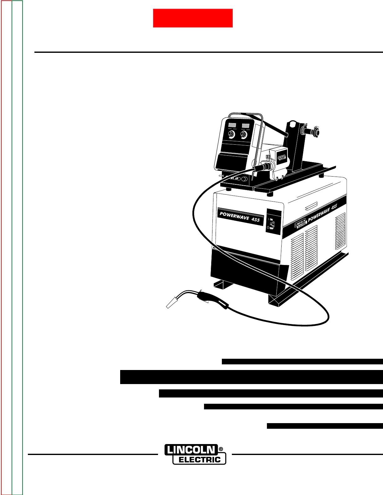
PPoowweerr WWaavvee 445555//PPoowweerr FFeeeedd 1100
SERVICE MANUAL
SVM135-B
July,2001
Safety Depends on You
Lincoln arc welding and cutting
equipment is designed and built
with safety in mind. However, your
overall safety can be increased by
proper installation ... and thought-
ful operation on your part. DO
NOT INSTALL, OPERATE OR
REPAIR THIS EQUIPMENT
WITHOUT READING THIS
MANUAL AND THE SAFETY
PRECAUTIONS CONTAINED
THROUGHOUT. And, most
importantly, think before you act
and be careful.
Return to Master TOC Return to Master TOC Return to Master TOC Return to Master TOC
View Safety Info View Safety Info View Safety Info View Safety Info
RETURN TO MAIN INDEX
• Sales and Service through Subsidiaries and Distributors Worldwide •
Cleveland, Ohio 44117-1199 U.S.A. TEL: 216.481.8100 FAX: 216.486.1751 WEB SITE: www.lincolnelectric.com
World's Leader in Welding and Cutting Products Premier Manufacturer of Industrial Motors
FOR ENGINE
powered equipment.
1.a. Turn the engine off before troubleshooting and maintenance
work unless the maintenance work requires it to be running.
____________________________________________________
1.b.Operate engines in open, well-ventilated
areas or vent the engine exhaust fumes
outdoors.
____________________________________________________
1.c. Do not add the fuel near an open flame
welding arc or when the engine is running.
Stop the engine and allow it to cool before
refueling to prevent spilled fuel from vaporiz-
ing on contact with hot engine parts and
igniting. Do not spill fuel when filling tank. If
fuel is spilled, wipe it up and do not start
engine until fumes have been eliminated.
____________________________________________________
1.d. Keep all equipment safety guards, covers
and devices in position and in good
repair.Keep hands, hair, clothing and tools
away from V-belts, gears, fans and all other
moving parts when starting, operating or
repairing equipment.
____________________________________________________
1.e. In some cases it may be necessary to remove safety
guards to perform required maintenance. Remove
guards only when necessary and replace them when the
maintenance requiring their removal is complete.
Always use the greatest care when working near moving
parts.
___________________________________________________
1.f. Do not put your hands near the engine fan. Do not attempt
to override the governor or idler by pushing on the throttle
control rods while the engine is running.
___________________________________________________
1.g. To prevent accidentally starting gasoline engines while
turning the engine or welding generator during maintenance
work, disconnect the spark plug wires, distributor cap or
magneto wire as appropriate.
i
SAFETY
i
ARC WELDING CAN BE HAZARDOUS. PROTECT YOURSELF AND OTHERS FROM POSSIBLE SERIOUS INJURY OR DEATH.
KEEP CHILDREN AWAY. PACEMAKER WEARERS SHOULD CONSULT WITH THEIR DOCTOR BEFORE OPERATING.
Read and understand the following safety highlights. For additional safety information, it is strongly recommended that you
purchase a copy of “Safety in Welding & Cutting - ANSI Standard Z49.1” from the American Welding Society, P.O. Box
351040, Miami, Florida 33135 or CSA Standard W117.2-1974. A Free copy of “Arc Welding Safety” booklet E205 is available
from the Lincoln Electric Company, 22801 St. Clair Avenue, Cleveland, Ohio 44117-1199.
BE SURE THAT ALL INSTALLATION, OPERATION, MAINTENANCE AND REPAIR PROCEDURES ARE
PERFORMED ONLY BY QUALIFIED INDIVIDUALS.
WARNING
Mar ‘95
ELECTRIC AND
MAGNETIC FIELDS
may be dangerous
2.a. Electric current flowing through any conductor causes
localized Electric and Magnetic Fields (EMF). Welding
current creates EMF fields around welding cables and
welding machines
2.b. EMF fields may interfere with some pacemakers, and
welders having a pacemaker should consult their physician
before welding.
2.c. Exposure to EMF fields in welding may have other health
effects which are now not known.
2.d. All welders should use the following procedures in order to
minimize exposure to EMF fields from the welding circuit:
2.d.1.
Route the electrode and work cables together - Secure
them with tape when possible.
2.d.2. Never coil the electrode lead around your body.
2.d.3. Do not place your body between the electrode and
work cables. If the electrode cable is on your right
side, the work cable should also be on your right side.
2.d.4. Connect the work cable to the workpiece as close as
possible to the area being welded.
2.d.5. Do not work next to welding power source.
1.h. To avoid scalding, do not remove the
radiator pressure cap when the engine is
hot.
CALIFORNIA PROPOSITION 65 WARNINGS
Diesel engine exhaust and some of its constituents
are known to the State of California to cause can-
cer, birth defects, and other reproductive harm.
The engine exhaust from this product contains
chemicals known to the State of California to cause
cancer, birth defects, or other reproductive harm.
The Above For Diesel Engines The Above For Gasoline Engines
Return to Master TOC Return to Master TOC Return to Master TOC Return to Master TOC
ii
SAFETY
ii
ARC RAYS can burn.
4.a. Use a shield with the proper filter and cover
plates to protect your eyes from sparks and
the rays of the arc when welding or observing
open arc welding. Headshield and filter lens
should conform to ANSI Z87. I standards.
4.b. Use suitable clothing made from durable flame-resistant
material to protect your skin and that of your helpers from
the arc rays.
4.c. Protect other nearby personnel with suitable, non-flammable
screening and/or warn them not to watch the arc nor expose
themselves to the arc rays or to hot spatter or metal.
ELECTRIC SHOCK can
kill.
3.a. The electrode and work (or ground) circuits
are electrically “hot” when the welder is on.
Do not touch these “hot” parts with your bare
skin or wet clothing. Wear dry, hole-free
gloves to insulate hands.
3.b. Insulate yourself from work and ground using dry insulation.
Make certain the insulation is large enough to cover your full
area of physical contact with work and ground.
In addition to the normal safety precautions, if welding
must be performed under electrically hazardous
conditions (in damp locations or while wearing wet
clothing; on metal structures such as floors, gratings or
scaffolds; when in cramped positions such as sitting,
kneeling or lying, if there is a high risk of unavoidable or
accidental contact with the workpiece or ground) use
the following equipment:
• Semiautomatic DC Constant Voltage (Wire) Welder.
• DC Manual (Stick) Welder.
• AC Welder with Reduced Voltage Control.
3.c. In semiautomatic or automatic wire welding, the electrode,
electrode reel, welding head, nozzle or semiautomatic
welding gun are also electrically “hot”.
3.d. Always be sure the work cable makes a good electrical
connection with the metal being welded. The connection
should be as close as possible to the area being welded.
3.e. Ground the work or metal to be welded to a good electrical
(earth) ground.
3.f.
Maintain the electrode holder, work clamp, welding cable and
welding machine in good, safe operating condition. Replace
damaged insulation.
3.g. Never dip the electrode in water for cooling.
3.h. Never simultaneously touch electrically “hot” parts of
electrode holders connected to two welders because voltage
between the two can be the total of the open circuit voltage
of both welders.
3.i. When working above floor level, use a safety belt to protect
yourself from a fall should you get a shock.
3.j. Also see Items 6.c. and 8.
FUMES AND GASES
can be dangerous.
5.a. Welding may produce fumes and gases
hazardous to health. Avoid breathing these
fumes and gases.When welding, keep
your head out of the fume. Use enough
ventilation and/or exhaust at the arc to keep
fumes and gases away from the breathing zone. When
welding with electrodes which require special
ventilation such as stainless or hard facing (see
instructions on container or MSDS) or on lead or
cadmium plated steel and other metals or coatings
which produce highly toxic fumes, keep exposure as
low as possible and below Threshold Limit Values (TLV)
using local exhaust or mechanical ventilation. In
confined spaces or in some circumstances, outdoors, a
respirator may be required. Additional precautions are
also required when welding on galvanized steel.
5.b.
Do not weld in locations near chlorinated hydrocarbon
vapors
coming from degreasing, cleaning or spraying operations.
The heat and rays of the arc can react with solvent vapors
to
form phosgene, a highly toxic gas, and other irritating
products.
5.c. Shielding gases used for arc welding can displace air and
cause injury or death. Always use enough ventilation,
especially in confined areas, to insure breathing air is safe.
5.d. Read and understand the manufacturer’s instructions for this
equipment and the consumables to be used, including the
material safety data sheet (MSDS) and follow your
employer’s safety practices. MSDS forms are available from
your welding distributor or from the manufacturer.
5.e. Also see item 1.b. Mar ‘95
Return to Master TOC Return to Master TOC Return to Master TOC Return to Master TOC
FOR ELECTRICALLY
powered equipment.
8.a. Turn off input power using the disconnect
switch at the fuse box before working on
the equipment.
8.b. Install equipment in accordance with the U.S. National
Electrical Code, all local codes and the manufacturer’s
recommendations.
8.c. Ground the equipment in accordance with the U.S. National
Electrical Code and the manufacturer’s recommendations.
CYLINDER may explode
if damaged.
7.a. Use only compressed gas cylinders
containing the correct shielding gas for the
process used and properly operating
regulators designed for the gas and
pressure used. All hoses, fittings, etc. should be suitable for
the application and maintained in good condition.
7.b. Always keep cylinders in an upright position securely
chained to an undercarriage or fixed support.
7.c. Cylinders should be located:
•Away from areas where they may be struck or subjected to
physical damage.
•A safe distance from arc welding or cutting operations and
any other source of heat, sparks, or flame.
7.d. Never allow the electrode, electrode holder or any other
electrically “hot” parts to touch a cylinder.
7.e. Keep your head and face away from the cylinder valve outlet
when opening the cylinder valve.
7.f. Valve protection caps should always be in place and hand
tight except when the cylinder is in use or connected for
use.
7.g. Read and follow the instructions on compressed gas
cylinders, associated equipment, and CGA publication P-l,
“Precautions for Safe Handling of Compressed Gases in
Cylinders,” available from the Compressed Gas Association
1235 Jefferson Davis Highway, Arlington, VA 22202.
iii
SAFETY
iii
Mar ‘95
WELDING SPARKS can
cause fire or explosion.
6.a.
Remove fire hazards from the welding area.
If this is not possible, cover them to prevent
the welding sparks from starting a fire.
Remember that welding sparks and hot
materials from welding can easily go through small cracks
and openings to adjacent areas. Avoid welding near
hydraulic lines. Have a fire extinguisher readily available.
6.b. Where compressed gases are to be used at the job site,
special precautions should be used to prevent hazardous
situations. Refer to “Safety in Welding and Cutting” (ANSI
Standard Z49.1) and the operating information for the
equipment being used.
6.c. When not welding, make certain no part of the electrode
circuit is touching the work or ground. Accidental contact
can cause overheating and create a fire hazard.
6.d. Do not heat, cut or weld tanks, drums or containers until the
proper steps have been taken to insure that such procedures
will not cause flammable or toxic vapors from substances
inside. They can cause an explosion even
though
they have
been “cleaned”. For information, purchase “Recommended
Safe Practices for the
Preparation
for Welding and Cutting of
Containers and Piping That Have Held Hazardous
Substances”, AWS F4.1 from the American Welding Society
(see address above).
6.e. Vent hollow castings or containers before heating, cutting or
welding. They may explode.
6.f.
Sparks and spatter are thrown from the welding arc. Wear oil
free protective garments such as leather gloves, heavy shirt,
cuffless trousers, high shoes and a cap over your hair. Wear
ear plugs when welding out of position or in confined places.
Always wear safety glasses with side shields when in a
welding area.
6.g. Connect the work cable to the work as close to the welding
area as practical. Work cables connected to the building
framework or other locations away from the welding area
increase the possibility of the welding current passing
through lifting chains, crane cables or other alternate cir-
cuits. This can create fire hazards or overheat lifting chains
or cables until they fail.
6.h. Also see item 1.c.
Return to Master TOC Return to Master TOC Return to Master TOC Return to Master TOC

iv
SAFETY
iv
PRÉCAUTIONS DE SÛRETÉ
Pour votre propre protection lire et observer toutes les instruc-
tions et les précautions de sûreté specifiques qui parraissent
dans ce manuel aussi bien que les précautions de sûreté
générales suivantes:
Sûreté Pour Soudage A L’Arc
1. Protegez-vous contre la secousse électrique:
a. Les circuits à l’électrode et à la piéce sont sous tension
quand la machine à souder est en marche. Eviter toujours
tout contact entre les parties sous tension et la peau nue
ou les vétements mouillés. Porter des gants secs et sans
trous pour isoler les mains.
b. Faire trés attention de bien s’isoler de la masse quand on
soude dans des endroits humides, ou sur un plancher
metallique ou des grilles metalliques, principalement dans
les positions assis ou couché pour lesquelles une
grande partie du corps peut être en contact avec la
masse.
c. Maintenir le porte-électrode, la pince de masse, le câble
de soudage et la machine à souder en bon et sûr état
defonctionnement.
d.Ne jamais plonger le porte-électrode dans l’eau pour le
refroidir.
e. Ne jamais toucher simultanément les parties sous tension
des porte-électrodes connectés à deux machines à soud-
er parce que la tension entre les deux pinces peut être le
total de la tension à vide des deux machines.
f. Si on utilise la machine à souder comme une source de
courant pour soudage semi-automatique, ces precautions
pour le porte-électrode s’applicuent aussi au pistolet de
soudage.
2. Dans le cas de travail au dessus du niveau du sol, se pro-
téger contre les chutes dans le cas ou on recoit un choc. Ne
jamais enrouler le câble-électrode autour de n’importe quelle
partie du corps.
3. Un coup d’arc peut être plus sévère qu’un coup de soliel,
donc:
a. Utiliser un bon masque avec un verre filtrant approprié
ainsi qu’un verre blanc afin de se protéger les yeux du
rayonnement de l’arc et des projections quand on soude
ou quand on regarde l’arc.
b. Porter des vêtements convenables afin de protéger la
peau de soudeur et des aides contre le rayonnement de
l‘arc.
c. Protéger l’autre personnel travaillant à proximité au
soudage à l’aide d’écrans appropriés et non-inflamma-
bles.
4. Des gouttes de laitier en fusion sont émises de l’arc de
soudage. Se protéger avec des vêtements de protection
libres de l’huile, tels que les gants en cuir, chemise épaisse,
pantalons sans revers, et chaussures montantes.
5. Toujours porter des lunettes de sécurité dans la zone de
soudage. Utiliser des lunettes avec écrans lateraux dans les
zones où l’on pique le laitier.
6. Eloigner les matériaux inflammables ou les recouvrir afin de
prévenir tout risque d’incendie dû aux étincelles.
7. Quand on ne soude pas, poser la pince à une endroit isolé de
la masse. Un court-circuit accidental peut provoquer un
échauffement et un risque d’incendie.
8. S’assurer que la masse est connectée le plus prés possible
de la zone de travail qu’il est pratique de le faire. Si on place
la masse sur la charpente de la construction ou d’autres
endroits éloignés de la zone de travail, on augmente le risque
de voir passer le courant de soudage par les chaines de lev-
age, câbles de grue, ou autres circuits. Cela peut provoquer
des risques d’incendie ou d’echauffement des chaines et des
câbles jusqu’à ce qu’ils se rompent.
9. Assurer une ventilation suffisante dans la zone de soudage.
Ceci est particuliérement important pour le soudage de tôles
galvanisées plombées, ou cadmiées ou tout autre métal qui
produit des fumeés toxiques.
10. Ne pas souder en présence de vapeurs de chlore provenant
d’opérations de dégraissage, nettoyage ou pistolage. La
chaleur ou les rayons de l’arc peuvent réagir avec les
vapeurs du solvant pour produire du phosgéne (gas forte-
ment toxique) ou autres produits irritants.
11. Pour obtenir de plus amples renseignements sur la sûreté,
voir le code “Code for safety in welding and cutting” CSA
Standard W 117.2-1974.
PRÉCAUTIONS DE SÛRETÉ POUR
LES MACHINES À SOUDER À
TRANSFORMATEUR ET À
REDRESSEUR
1. Relier à la terre le chassis du poste conformement au code
de l’électricité et aux recommendations du fabricant. Le dis-
positif de montage ou la piece à souder doit être branché à
une bonne mise à la terre.
2. Autant que possible, I’installation et l’entretien du poste
seront effectués par un électricien qualifié.
3. Avant de faires des travaux à l’interieur de poste, la
debrancher à l’interrupteur à la boite de fusibles.
4. Garder tous les couvercles et dispositifs de sûreté à leur
place.
Mar. ‘93
Return to Master TOC Return to Master TOC Return to Master TOC Return to Master TOC

POWER WAVE 455/POWER FEED 10
v
MASTER TABLE OF CONTENTS FOR ALL SECTIONS Page
Safety . . . . . . . . . . . . . . . . . . . . . . . . . . . . . . . . . . . . . . . . . . . . . . . . . . . . . . . . . . . . . . . . . . . . . . . . . . . i-iv
Installation . . . . . . . . . . . . . . . . . . . . . . . . . . . . . . . . . . . . . . . . . . . . . . . . . . . . . . . . . . . . . . . . . . . . . . . Section A
Technical Specifications - Power Feed 10 Wire Drive and Control Box . . . . . . . . . . . . . . . . . . . . . . A-2
Technical Specifications - Power Wave 455 . . . . . . . . . . . . . . . . . . . . . . . . . . . . . . . . . . . . . . . . . . . A-3
Safety Precautions . . . . . . . . . . . . . . . . . . . . . . . . . . . . . . . . . . . . . . . . . . . . . . . . . . . . . . . . . . . . . . A-4
Location and Mounting . . . . . . . . . . . . . . . . . . . . . . . . . . . . . . . . . . . . . . . . . . . . . . . . . . . . . . . . . . . A-4
Electrical Connections . . . . . . . . . . . . . . . . . . . . . . . . . . . . . . . . . . . . . . . . . . . . . . . . . . . . . . . . . . . A-6
Cable Connections . . . . . . . . . . . . . . . . . . . . . . . . . . . . . . . . . . . . . . . . . . . . . . . . . . . . . . . . . . . . . . A-7
Wire Feeder Setup . . . . . . . . . . . . . . . . . . . . . . . . . . . . . . . . . . . . . . . . . . . . . . . . . . . . . . . . . . . . . . A-9
Operation . . . . . . . . . . . . . . . . . . . . . . . . . . . . . . . . . . . . . . . . . . . . . . . . . . . . . . . . . . . . . . . . . . . . . . . . Section B
Operating Instructions . . . . . . . . . . . . . . . . . . . . . . . . . . . . . . . . . . . . . . . . . . . . . . . . . . . . . . . . . . . . B-2
Safety Instructions . . . . . . . . . . . . . . . . . . . . . . . . . . . . . . . . . . . . . . . . . . . . . . . . . . . . . . . . . . . . . . B-2
System Description . . . . . . . . . . . . . . . . . . . . . . . . . . . . . . . . . . . . . . . . . . . . . . . . . . . . . . . . . . . . . . B-2
Controls and Settings . . . . . . . . . . . . . . . . . . . . . . . . . . . . . . . . . . . . . . . . . . . . . . . . . . . . . . . . . . . . B-3
Weld Mode Descriptions . . . . . . . . . . . . . . . . . . . . . . . . . . . . . . . . . . . . . . . . . . . . . . . . . . . . . . . . . . B-6
Electrode Routing . . . . . . . . . . . . . . . . . . . . . . . . . . . . . . . . . . . . . . . . . . . . . . . . . . . . . . . . . . . . . . . B-6
Wire Spindle Replacement . . . . . . . . . . . . . . . . . . . . . . . . . . . . . . . . . . . . . . . . . . . . . . . . . . . . . . . . B-7
Wire Reel Loading - Readi-Reels, Spools or Coils . . . . . . . . . . . . . . . . . . . . . . . . . . . . . . . . . . . . . . B-7
Feeding Electrode and Brake Adjustment . . . . . . . . . . . . . . . . . . . . . . . . . . . . . . . . . . . . . . . . . . . . B-9
Drive Roll Kit Installation (KP1505-[]) . . . . . . . . . . . . . . . . . . . . . . . . . . . . . . . . . . . . . . . . . . . . . . . . B-9
Drive Roll Pressure Setting . . . . . . . . . . . . . . . . . . . . . . . . . . . . . . . . . . . . . . . . . . . . . . . . . . . . . . . . B-9
Procedure For Setting Angle of Feedplate . . . . . . . . . . . . . . . . . . . . . . . . . . . . . . . . . . . . . . . . . . . . B-9
Wire Feed Overload Protection . . . . . . . . . . . . . . . . . . . . . . . . . . . . . . . . . . . . . . . . . . . . . . . . . . . . . B-10
Accessories . . . . . . . . . . . . . . . . . . . . . . . . . . . . . . . . . . . . . . . . . . . . . . . . . . . . . . . . . . . . . . . . . . . . . . Section C
General . . . . . . . . . . . . . . . . . . . . . . . . . . . . . . . . . . . . . . . . . . . . . . . . . . . . . . . . . . . . . . . . . . . . . . . C-2
Power Wave Options and Accessories . . . . . . . . . . . . . . . . . . . . . . . . . . . . . . . . . . . . . . . . . . . . . . . C-3
Wire Feeder Options and Accessories . . . . . . . . . . . . . . . . . . . . . . . . . . . . . . . . . . . . . . . . . . . . . . . C-3
Maintenance . . . . . . . . . . . . . . . . . . . . . . . . . . . . . . . . . . . . . . . . . . . . . . . . . . . . . . . . . . . . . . . . . . . . . . Section D
Safety Precautions . . . . . . . . . . . . . . . . . . . . . . . . . . . . . . . . . . . . . . . . . . . . . . . . . . . . . . . . . . . . . . D-2
Routine Maintenance . . . . . . . . . . . . . . . . . . . . . . . . . . . . . . . . . . . . . . . . . . . . . . . . . . . . . . . . . . . . D-2
Periodic Maintenance . . . . . . . . . . . . . . . . . . . . . . . . . . . . . . . . . . . . . . . . . . . . . . . . . . . . . . . . . . . . D-2
Theory of Operation . . . . . . . . . . . . . . . . . . . . . . . . . . . . . . . . . . . . . . . . . . . . . . . . . . . . . . . . . . . . . . . Section E
Troubleshooting and Repair . . . . . . . . . . . . . . . . . . . . . . . . . . . . . . . . . . . . . . . . . . . . . . . . . . . . . . . . Section F
How to Use Troubleshooting Guide . . . . . . . . . . . . . . . . . . . . . . . . . . . . . . . . . . . . . . . . . . . . . . . . . F-2
PC Board Troubleshooting Procedures . . . . . . . . . . . . . . . . . . . . . . . . . . . . . . . . . . . . . . . . . . . . . . F-3
Troubleshooting Guide . . . . . . . . . . . . . . . . . . . . . . . . . . . . . . . . . . . . . . . . . . . . . . . . . . . . . . . . . . . F-5
Test Procedures . . . . . . . . . . . . . . . . . . . . . . . . . . . . . . . . . . . . . . . . . . . . . . . . . . . . . . . . . . . . . . . . F-23
Component Replacement Procedures . . . . . . . . . . . . . . . . . . . . . . . . . . . . . . . . . . . . . . . . . . . . . . . F-61
Electrical Diagrams . . . . . . . . . . . . . . . . . . . . . . . . . . . . . . . . . . . . . . . . . . . . . . . . . . . . . . . . . . . . . . . . Section G
Parts
Parts List Power Wave 455 . . . . . . . . . . . . . . . . . . . . . . . . . . . . . . . . . . . . . . . . . . . . . . . . . . . . . . . . P-291
Parts List Power Feed 10 . . . . . . . . . . . . . . . . . . . . . . . . . . . . . . . . . . . . . . . . . . . . . . . . . . . . . . . . . P-306
vRETURN TO MAIN INDEX

SECTION A-1
INSTALLATION
POWER WAVE 455/POWER FEED 10
SECTION A-1
TABLE OF CONTENTS
-INSTALLATION SECTION-
Installation . . . . . . . . . . . . . . . . . . . . . . . . . . . . . . . . . . . . . . . . . . . . . . . . . . . . . . . . . . . . . . . . . . . . . . . . Section A
Technical Specifications - Power Feed 10 Wire Drive and Control Box . . . . . . . . . . . . . . . . . . . . . . A-2
Technical Specifications - Power Wave 455 . . . . . . . . . . . . . . . . . . . . . . . . . . . . . . . . . . . . . . . . . . . A-3
Safety Precautions . . . . . . . . . . . . . . . . . . . . . . . . . . . . . . . . . . . . . . . . . . . . . . . . . . . . . . . . . . . . . . A-4
Location and Mounting . . . . . . . . . . . . . . . . . . . . . . . . . . . . . . . . . . . . . . . . . . . . . . . . . . . . . . . . . . . A-4
Stacking . . . . . . . . . . . . . . . . . . . . . . . . . . . . . . . . . . . . . . . . . . . . . . . . . . . . . . . . . . . . . . . . . . . A-4
Environment . . . . . . . . . . . . . . . . . . . . . . . . . . . . . . . . . . . . . . . . . . . . . . . . . . . . . . . . . . . . . . . . A-4
Lifting . . . . . . . . . . . . . . . . . . . . . . . . . . . . . . . . . . . . . . . . . . . . . . . . . . . . . . . . . . . . . . . . . . . . . A-4
Feeder and Control Box Mounting . . . . . . . . . . . . . . . . . . . . . . . . . . . . . . . . . . . . . . . . . . . . . . . A-4
Electrical Connections . . . . . . . . . . . . . . . . . . . . . . . . . . . . . . . . . . . . . . . . . . . . . . . . . . . . . . . . . . . A-6
Grounding . . . . . . . . . . . . . . . . . . . . . . . . . . . . . . . . . . . . . . . . . . . . . . . . . . . . . . . . . . . . . . . . . . A-6
High Frequency Interference Protection . . . . . . . . . . . . . . . . . . . . . . . . . . . . . . . . . . . . . . . . . . . A-6
Input Fuse and Supply Wire Considerations . . . . . . . . . . . . . . . . . . . . . . . . . . . . . . . . . . . . . . . A-6
Input Voltage Reconnect Procedure . . . . . . . . . . . . . . . . . . . . . . . . . . . . . . . . . . . . . . . . . . . . . . A-6
Cable Connections . . . . . . . . . . . . . . . . . . . . . . . . . . . . . . . . . . . . . . . . . . . . . . . . . . . . . . . . . . . . . . A-7
Control Cable Connections . . . . . . . . . . . . . . . . . . . . . . . . . . . . . . . . . . . . . . . . . . . . . . . . . . . . . A-7
Flexible Connection Possibilities . . . . . . . . . . . . . . . . . . . . . . . . . . . . . . . . . . . . . . . . . . . . . . . . A-7
Cable Connections . . . . . . . . . . . . . . . . . . . . . . . . . . . . . . . . . . . . . . . . . . . . . . . . . . . . . . . . . . . A-8
Electrode and Work Leads — Electrode Positive Applications . . . . . . . . . . . . . . . . . . . . . . . . . A-8
Electrode and Work Leads — Electrode Negative Applications . . . . . . . . . . . . . . . . . . . . . . . . . A-9
Voltage Sensing at the Workpiece . . . . . . . . . . . . . . . . . . . . . . . . . . . . . . . . . . . . . . . . . . . . . . . A-9
Wire Feeder Setup . . . . . . . . . . . . . . . . . . . . . . . . . . . . . . . . . . . . . . . . . . . . . . . . . . . . . . . . . . . . . . A-9
Wire Drive Gear Ratio (High or Low Speed) . . . . . . . . . . . . . . . . . . . . . . . . . . . . . . . . . . . . . . . A-9
DIP Switch Setup . . . . . . . . . . . . . . . . . . . . . . . . . . . . . . . . . . . . . . . . . . . . . . . . . . . . . . . . . . . . A-11
Gun and Cable Assemblies . . . . . . . . . . . . . . . . . . . . . . . . . . . . . . . . . . . . . . . . . . . . . . . . . . . . A-15
GMAW Shielding Gas . . . . . . . . . . . . . . . . . . . . . . . . . . . . . . . . . . . . . . . . . . . . . . . . . . . . . . . . . A-15
Standard Panel Installation . . . . . . . . . . . . . . . . . . . . . . . . . . . . . . . . . . . . . . . . . . . . . . . . . . . . . A-16
Return to Master TOC Return to Master TOC Return to Master TOC Return to Master TOC

A-2
POWER WAVE 455/POWER FEED 10
A-2 INSTALLATION
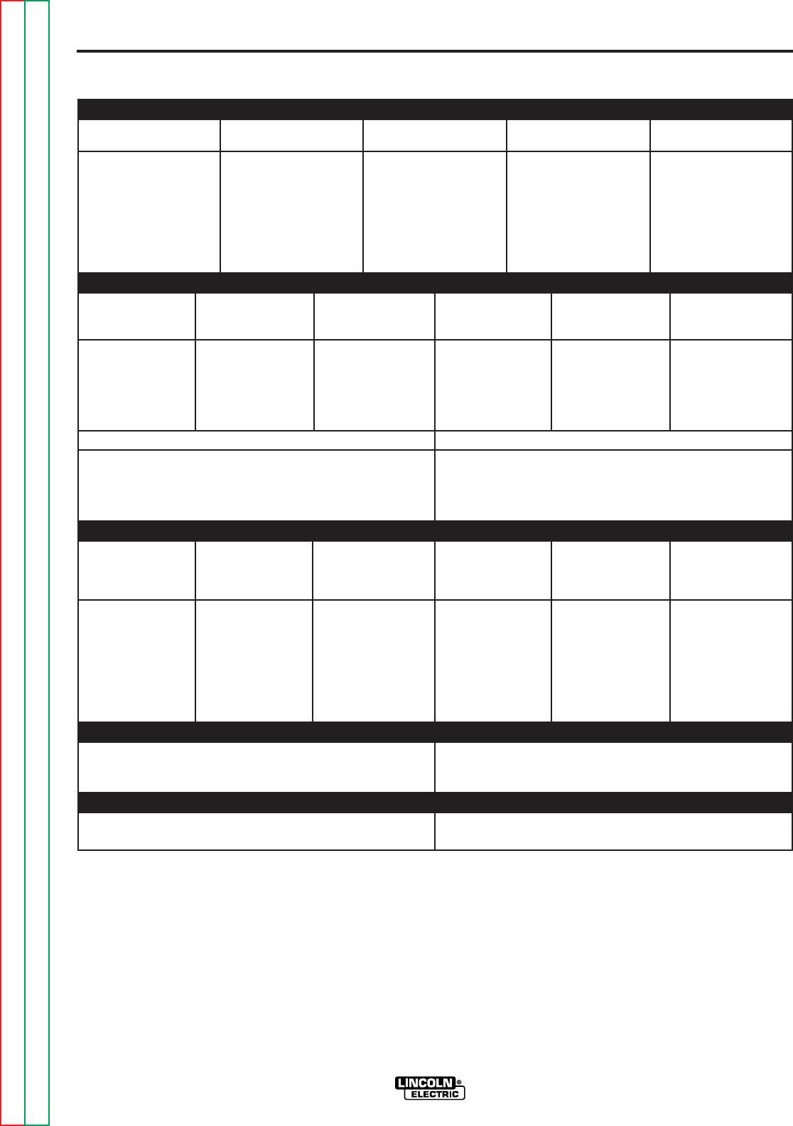
TECHNICAL SPECIFICATIONS – POWER FEED 10 WIRE DRIVE AND
CONTROL BOX
WIRE DRIVE OR WIRE DRIVE SECTION OF FEEDER
SPEC # TYPE LOW SPEED RATIO HIGH SPEED RATIO
* Included with K1538-1 Boom package and K1541-1 Bench Feeder.
∆Dimensions do not include wire reel.
# For Control Box and Wire Drive dimensions and weights, see individual component listings.
Wire Size Wire Size
Speed Solid Cored Speed Solid Cored
K1540-1
Power Feed 10
50-800 IPM .025 - 3/32 in. .035 - .125 in. 75 - 1200 IPM .025 - 1/16 in. .035 - 5/64 in.
Wire Drive (1.27-20.3 m/m) (0.6 - 2.4 mm) (0.9 - 3.2 mm) (2.03 - 30.5 m/m) (0.6 - 1.6 mm) (0.9 - 2.0 mm)
K1538-1
Power Feed 10
50-800 IPM .025 - 3/32 in. .035 - .125 in. 75 - 1200 IPM .025 - 1/16 in. .035 - 5/64 in.
Boom Package#
(1.27-20.3 m/m) (0.6 - 2.4 mm) (0.9 - 3.2 mm) (2.03 - 30.5 m/m) (0.6 - 1.6 mm) (0.9 - 2.0 mm)
K1541-1
Power Feed 10
50-800 IPM .025 - 3/32 in. .035 - .125 in. 75 - 1200 IPM .025 - 1/16 in. .035 - 5/64 in.
Bench Model (1.27-20.3 m/m) (0.6 - 2.4 mm) (0.9 - 3.2 mm) (2.03 - 30.5 m/m) (0.6 - 1.6 mm) (0.9 - 2.0 mm)
Drive and
Control Box
CONTROL BOX, WIRE DRIVE AND COMPLETE UNITS
SPEC.# TYPE INPUT POWER PHYSICAL SIZE• TEMPERATURE RATING
Dimensions
Height Width Depth Weight Operating Storage
K1539-1 Power 40 VDC 13.0 in. 8.50 in. 4.0 in. 8.5 lbs
(Control Feed 10 (330 mm) ( 215 mm) (105 mm) (3.8 kg)
Box Control
Only)*Box
K1540-1 Power 40 VDC 7.6 in. 12.9 in. 13.7 in. 30 lbs +40˚C +40˚C
(Wire Feed 10 (195 mm) (325 mm) (345 mm) (13.6 kg) to to
Drive Wire -20˚C -40˚C
Only)*Drive
K1541-1 Power 40 VDC 18.5 in. 13.5 in. 30.5 in. 62 lbs
Bench Feed 10 ( 470 mm) (345 mm) (775 mm) (28.1 kg.)
Model
Bench Model
Feeder∆Drive and
Control Box
Return to Section TOC Return to Section TOC Return to Section TOC Return to Section TOC
Return to Master TOC Return to Master TOC Return to Master TOC Return to Master TOC
A-3
INSTALLATION
POWER WAVE 455/POWER FEED 10
A-3
RECOMMENDED INPUT WIRE AND FUSE SIZES
PHYSICAL DIMENSIONS
TEMPERATURE RANGES
INPUT AT RATED OUTPUT - THREE PHASE ONLY
Input Volts
208V - 60Hz
230V - 60Hz
400V - 60Hz
460V - 60Hz
200V - 50Hz
220V - 50Hz
400V - 50Hz
440V - 50Hz
Open
Circuit
Voltage
75 VDC
Input
Voltage /
Frequency
208/60/50
230/60/50
400/60/50
460/60/50
208/60/50
230/60/50
400/60/50
460/60/50
Height
26.10 in.
663 mm
Width
19.86 in.
505 mm
Depth
32.88 in.
835 mm
Weight
250 lbs
114 kg
Type 75°C
(Super Lag)
or Breaker
Size (AMPS)
80
70
50
40
90
90
60
50
Type 75°C
Ground Wire in
Conduit AWG[IEC]
Sizes (mm2)
8 (10)
8 (10)
10 (6)
10 (6)
8 (10)
8 (10)
8 (6)
8 (6)
Type 75°C
Copper Wire in
Conduit AWG[IEC]
Sizes (mm2)
4 (25)
4 (25)
8 (10)
8 (10)
4 (25)
4 (25)
6 (10)
6 (10)
Input Ampere Rating
on Nameplate (AMPS)
70/72
65/67
39/40
35/36
87/79
82/74
50/45
48/41
Duty
Cycle
100%
100%
100%
100%
60%*
60%*
60%*
60%*
Process Current Ranges (DC)
MIG/MAG
FCAW
SMAW
Pulse
Current
50-570 Amps
40-570 Amps
30-570 Amps
5-750 Amps
Pulse
Voltage
Range
5 - 55 VDC
Auxiliary
Power
40 VDC AT
10 AMPS
115 VAC AT
10 AMPS
Pulse and
Background
Time Range
100 MICRO SEC. -
3.3 SEC.
Current Range
5 - 570
Pulse
Frequency
0.15 - 1000 Hz
Input
Current
70
65
39
35
72
67
40
36
Input
Current
87
82
50
48
79
74
45
41
Rated Output @
100% Duty Cycle
450A@38V 100%
450A@38V 100%
450A@38V 100%
450A@38V 100%
450A@38V 100%
450A@38V 100%
450A@38V 100%
450A@38V 100%
Rated Output @
60% Duty Cycle
570A@43V 60%
570A@43V 60%
570A@43V 60%
570A@43V 60%
500A@40V 60%
500A@40V 60%
500A@40V 60%
500A@40V 60%
Operating Temperature Range
0°C to 40°C Storage Temperature Range
-50°C to 85°C
TECHNICAL SPECIFICATIONS – POWER WAVE 455
OUTPUT
*At 60% duty cycle with 50Hz input power, the machine is de-rated to 500 Amps at 40V.
Return to Section TOC Return to Section TOC Return to Section TOC Return to Section TOC
Return to Master TOC Return to Master TOC Return to Master TOC Return to Master TOC
A-4
INSTALLATION
POWER WAVE 455/POWER FEED 10
A-4
SAFETY PRECAUTIONS
ELECTRIC SHOCK
can kill.
• Only qualified personnel should per-
form this installation.
• Turn off the input power to the power
source at the disconnect switch or
fuse box before working on this equip-
ment. Turn off the input power to any
other equipment connected to the
welding system at the disconnect
switch or fuse box before working on
this equipment.
• Do not touch electrically hot parts.
• Always connect the Power Wave
grounding lug (located inside the
reconnect input access door) to a
proper safety (Earth) ground.
-----------------------------------------------------------
LOCATION AND MOUNTING
Place the welder where clean cooling air can freely
circulate in through the rear louvers and out through
the case sides and bottom. Dirt, dust, or any foreign
material that can be drawn into the welder should be
kept at a minimum. Using filters on the air intake to
prevent dirt from building up restricts air flow. Do
not use such filters. Failure to observe these precau-
tions can result in excessive operating temperatures
and nuisance shutdowns.
STACKING
Power Wave machines can be stacked to a maxi-
mum of three high. The bottom machine must
always be placed on a firm, secure, level surface.
There is a danger of machines toppling over if this
precaution is not taken.
ENVIRONMENT
The Power Wave power source carries an IP21 envi-
ronmental rating. If subjected to occasional falling
water, such as rain, the machine should be sheltered.
LIFTING
Lift the machine by the lift bail only. The lift bail is
designed to lift the power source only. Do not
attempt to lift the Power Wave with accessories
attached to it.
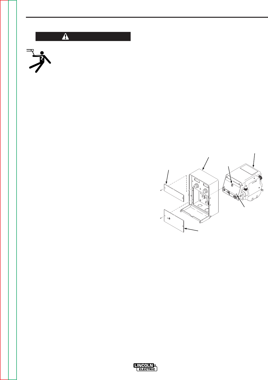
FEEDER AND CONTROL BOX
MOUNTING
SEPARATION FROM BENCH MODEL
The Control Box can be removed from the bench
model feeder and mounted in a different location.
See Figure A-1.
FIGURE A.1 — SEPARATING CONTROL BOX
AND FEEDER.
Complete the following steps to remove the Control
Box:
1. Remove the bottom and center option panels
from the front of the Control Box.
2. Disconnect the connector between the Control
Box and the wire drive located in the middle of
the Control Box back near the bottom of the
Control Box.
WIRE
DRIVE
CENTER
PANEL
CONTROL
BOX
BOTTOM
PANEL
CONNECTOR
MOUNTING
SCREW
WARNING
Return to Section TOC Return to Section TOC Return to Section TOC Return to Section TOC
Return to Master TOC Return to Master TOC Return to Master TOC Return to Master TOC

A-5
INSTALLATION
POWER WAVE 455/POWER FEED 10
A-5
3. Loosen the four screws inside the Control Box
located along the sides of the back of the Control
Box, two near the bottom and two near the mid-
dle.
4. Push the Control Box upwards and then pull the
Control Box away from the wire drive.
5. Remove plug button taped to inside of Control
Box and insert it into hole on front panel of wire
drive.
BOOM MOUNTING
If you wish to convert to a boom mount, the follow-
ing components are required to complete the conver-
sion process:
Item 1 K1549-1 Receptacle
Item 2 K1550-1 Receptacle
Assemble the components above as follows:
1. Remove plug button and mount item 1 to the left
hole in the bottom of the Control Box.
2. Remove and save plug button and mount item 2
to the right hole in the bottom of the Control Box.
3. Insert connector from item 1 into either 4-pin
connector on Control Box motherboard.
4. Insert 6-pin connector that went to wire drive unit
into item 2.
5. Connect sense lead from item 1 to sense lead
from 6-pin connector that went to wire drive unit.
6. Replace all option panels removed from front of
Control Box.
7. Place plug button saved in step 2 into hole in
back panel of Control Box.
CONTROL BOX POWER SOURCE MOUNTING
The Power Feed Control Box can be directly mount-
ed on the front of the power source. If this control
location is preferred, complete the following steps to
mount Control Box on the power source:
1. Remove the bottom and center option panels
from the front of the Control Box.
2. Mount Control Box to the power source, follow-
ing the instructions supplied with that specific
power source.
3. If the Control Box has an input Amphenol con-
nector mounted on right side of bottom, then dis-
connect it’s 6-pin electrical connector from the
input connector inside the Control Box.
NOTE: This input connector no longer functions.
4. Connect 6-pin connector that comes out of the
back of the Control Box to the 6 pin connector.
(See specific power source instructions.)
5. 67 sense lead from left bottom connector (if pre-
sent) should be connected to 67 sense lead con-
nection from 6-pin connector from motherboard.
6. Replace all option panels removed from front of
Control Box.
Return to Section TOC Return to Section TOC Return to Section TOC Return to Section TOC
Return to Master TOC Return to Master TOC Return to Master TOC Return to Master TOC

A-6
INSTALLATION
POWER WAVE 455/POWER FEED 10
A-6
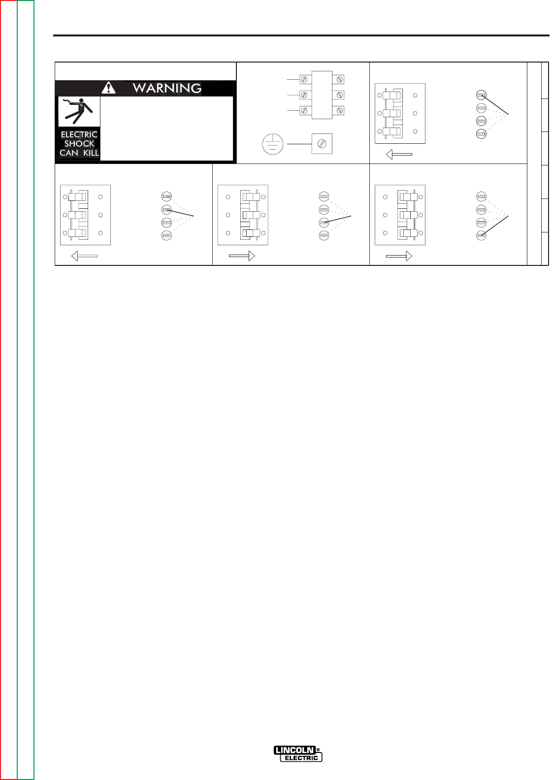
ELECTRICAL CONNECTIONS
Only a qualified electrician should connect the
input leads to the Power Wave. Connections
should be made in accordance with all local and
national electrical codes and the connection dia-
gram located on the inside of the reconnect/input
access door of the machine. Failure to do so
may result in bodily injury or death.
-----------------------------------------------------------
Use a three-phase supply line. An access hole for
the input supply is located on the upper left case
back next to the input access door. Connect L1, L2,
L3 and ground according to the Input Supply
Connection Diagram decal located on the inside of
the input access door or refer to Figure A.2.
GROUNDING
The frame of the welder must be grounded. A
ground terminal marked with the symbol is
located inside the reconnect/input access door for
this purpose. See your local and national electrical
codes for proper grounding methods. Refer to the
Technical Specifications
at the beginning of this
chapter for proper cable sizes.
HIGH FREQUENCY INTERFERENCE
PROTECTION
If possible, locate the Power Wave away from radio
controlled machinery. The normal operation of the
Power Wave may adversely affect the operation of
RF controlled equipment, which may result in bodily
injury or damage to the equipment.
INPUT FUSE AND SUPPLY WIRE
CONSIDERATIONS
Refer to the
Technical Specifications
at the begin-
ning of this Installation section for recommended fuse
and wire sizes. Fuse the input circuit with the recom-
mended super lag fuse or delay type breakers (also
called “inverse time” or “thermal/magnetic” circuit
breakers). Choose an input and grounding wire size
according to local or national electrical codes. Using
fuses or circuit breakers smaller than recommended
may result in “nuisance” shut-offs from welder inrush
currents, even if the machine is not being used at
high currents.
INPUT VOLTAGE RECONNECT
PROCEDURE
Turn main input power to the machine OFF
before performing reconnect procedure. Failure
to do so will result in damage to the machine.
DO NOT switch the reconnect bar with machine
power ON.
-----------------------------------------------------------
Welders are shipped connected for the highest input
voltage listed on the rating plate. To connect to a dif-
ferent input voltage, refer to reconnect instructions
located on the inside of the input access door or in
Figure A.2. If the main reconnect switch is placed in
the wrong position, the welder will not produce output
power. If the Auxiliary (“A”) lead is placed in the
wrong position, there are two possible results. If the
lead is placed in a position higher than the applied
line voltage, the welder may not come on at all. If the
Auxiliary (“A”) lead is placed in a position lower than
the applied line voltage, the welder will not come on,
and the two circuit breakers in the reconnect area will
open. If this occurs, turn off the input voltage, prop-
erly connect the “A” lead, reset the breakers, and try
again.
WARNING
WARNING
Return to Section TOC Return to Section TOC Return to Section TOC Return to Section TOC
Return to Master TOC Return to Master TOC Return to Master TOC Return to Master TOC
A-7
INSTALLATION
POWER WAVE 455/POWER FEED 10
A-7
CABLE CONNECTIONS
CONTROL CABLE CONNECTIONS
• All system control cables are the same but can
vary in length.
• All control cables can be connected end to end to
extend their length.
• All system equipment must be connected to a
control cable.
Welding systems using the Power Feed 10 offer pre-
viously unprecedented flexibility in the connection of
system components. This system uses the same
type of control cable between each of the system
components. Connections can be “daisy chained”
from one system component to another. Since com-
munication over the control cables is done by a
robust communications network, the order of connec-
tion of the components makes no difference. The
cables can be connected anywhere that there is a
mating connector. See the flexible connections part
of this section for more details.
NOTE: Maximum cable length between any two
nodes is 250 feet.
TYPICAL BENCH FEEDER CONNECTION
Control cable is connected from Power Source (PS)
to Feed Head (FH). If the Control Box is separated
from the FH, a control cable will connect from the PS
to the control box, which will have two control cable
connectors. This could be the control box or the FH
control box depending on how the units were sepa-
rated. A second control cable would be connected
from the second connector on the control box to the
other FH control box.
TYPICAL BOOM FEEDER CONNECTION
Control cable is connected from PS to the control
box. A second control cable would be connected
from the second connector on the control box to the
FH control box.
FLEXIBLE CONNECTION POSSIBILITIES
By using connector kits, a second connector can be
added to the Control box or the FH. This allows the
user to connect equipment types together in any
order.
FIGURE A.2 — CONNECTION DIAGRAM ON RECONNECT/INPUT ACCESS DOOR.
200-208V
220-230V
380-415V
440-460V
200-208V
220-230V
VOLTAGE=220-230V
220-230V
200-208V
220-230V
380-415V
440-460V
200-208V
U / L1
440-460V
380-415V
.
inspecting or servicing machine.
Do not operate with covers
.
removed.
Do not touch electrically live parts.
.
Only qualified persons should install,
use or service this equipment.
.
'A'
'A'
VOLTAGE=380-415V
'A'
S23847
VOLTAGE=200-208V
THE LINCOLN ELECTRIC CO. CLEVELAND, OHIO U.S.A.
A
'A'
VOLTAGE=440-460V
CR1
W / L3
V / L2
380-415V
440-460V
Disconnect input power before
INPUT SUPPLY CONNECTION DIAGRAM
Return to Section TOC Return to Section TOC Return to Section TOC Return to Section TOC
Return to Master TOC Return to Master TOC Return to Master TOC Return to Master TOC
A-8
INSTALLATION
POWER WAVE 455/POWER FEED 10
A-8
CONTROL CABLE SPECIFICATIONS
The cable is a five copper conductor cable in a SO-
type rubber jacket. There is one 20 gauge twisted
pair for network communications. This pair has an
impedance of approximately 120 ohms and a propa-
gation delay per foot of < 2.1 ns. There are two 12
gauge conductors that are used to supply the 40
VDC to the network. The fifth wire is 18 gauge and is
used as an electrode sense lead. It is typically con-
nected to the feed plate on the feed head when that
feed head is active.
AVAILABLE CABLE ASSEMBLIES
K1543 Control cable only. Available in lengths of
8, 16, 25, 50 and 100 feet.
K1544 Control cable and a 3/0 (85 mm2 ) electrode
cable with stud terminal. It is rated at 600
amps, 60% duty cycle and is available in
lengths of 8, 16, 25, and 50 feet.
K1545 Control cable and a 3/0 (85 mm2) electrode
cable with Twist-Mate™ connector on one
end and a stud terminal on the other. It is
rated at 500 amps, 60% duty cycle and is
available in lengths of 8, 16, 25, and 50 feet.
CABLE CONNECTIONS
To avoid interference problems with other equipment
and to achieve the best possible operation, route all
cables directly to the work or wire feeder. Avoid
excessive lengths, bundle the electrode and ground
cables together where practical, and do not coil
excess cable. Be sure the connection to the work
makes tight metal-to-metal electrical contact.
Minimum work and electrode cables sizes are as fol-
lows:
When using an inverter type power source, use the
largest welding (electrode and ground) cables that
are practical. At least 2/0 copper wire — even if the
average output current would not normally require it.
When pulsing, the pulse current can reach very high
levels. Voltage drops can become excessive, lead-
ing to poor welding characteristics, if undersized
welding cables are used.
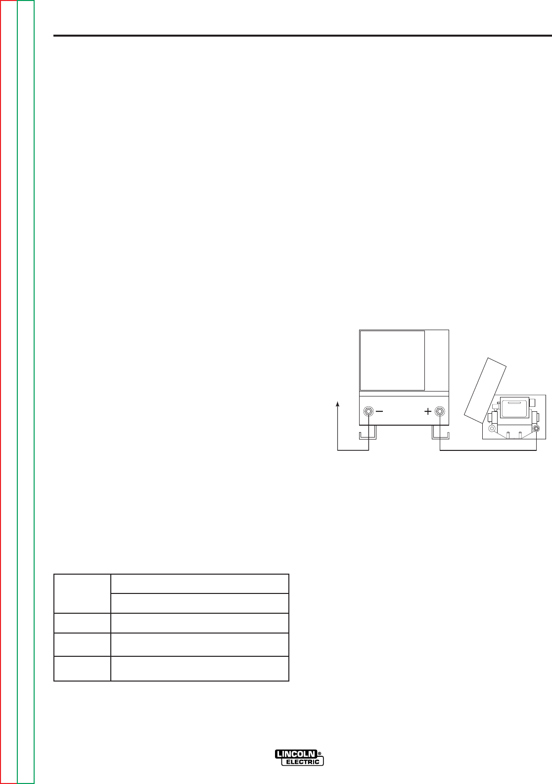
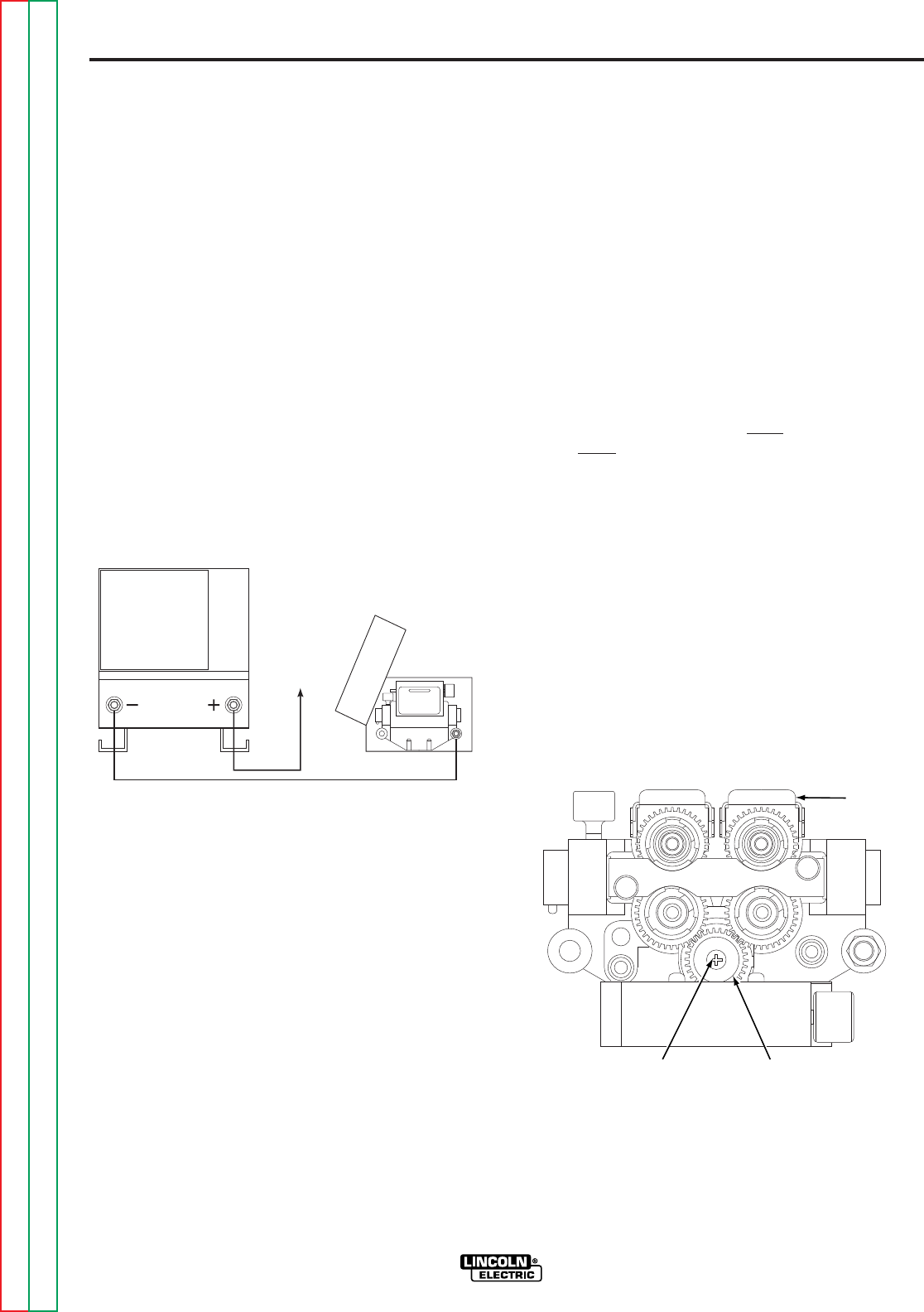
ELECTRODE AND WORK LEADS —
ELECTRODE POSITIVE APPLICATIONS
Most welding applications run with the electrode
being positive (+). For those applications, connect
the electrode cable between the wire feeder and the
positive (+) output stud on the power source (located
beneath the spring loaded output cover near the bot-
tom of the case front). See Figure A.3.
FIGURE A.3 — ELECTRODE POSITIVE
APPLICATION.
A work lead must be run from the negative (-) power
source output stud to the work piece. The work
piece connection must be firm and secure, especially
if pulse welding is planned. Excessive voltage drops
at the work piece connection often result in unsatis-
factory pulse welding performance.
Minimum Copper Work Cable Size, AWG
Up to 100 ft Length (30m)
Current
60% Duty
Cycle
400 Amps
500 Amps
600 Amps
2/0 (67 mm2)
3/0 (85 mm2)
3/0 (85 mm2)
POWER WAVE
WIRE
FEEDER
TO
WORK
Return to Section TOC Return to Section TOC Return to Section TOC Return to Section TOC
Return to Master TOC Return to Master TOC Return to Master TOC Return to Master TOC
A-9
INSTALLATION
POWER WAVE 455/POWER FEED 10
A-9
ELECTRODE AND WORK LEADS —
ELECTRODE NEGATIVE APPLICATIONS
When negative electrode polarity is required, such as
in some Innershield™ applications, install as above,
except reverse the output connections at the power
source (electrode cable to the negative (-) stud, and
work cable to the positive (+) stud). See Figure A.4.
VOLTAGE SENSING AT THE WORK-
PIECE
A four-pin voltage sense lead connector is located
beneath the output stud cover. In certain installa-
tions, where the work connection is poor, arc perfor-
mance may be improved by the use of an external
voltage sensing lead. Contact the factory for informa-
tion on connecting and using this feature.
FIGURE A.4 — ELECTRODE NEGATIVE
APPLICATION.
WIRE FEEDER SETUP
WIRE DRIVE GEAR RATIO (HIGH OR
LOW SPEED)
The speed range capability and drive torque of the
Power Feed 10 wire drive can be easily and quickly
changed by changing the external drive gear. The
Power Feed 10 is shipped with both a high speed
and a low speed gear. As shipped from the factory,
the low speed (high torque) gear is installed on the
feeder. If this is the desired gear ratio, no changes
need to be made.
SELECTING THE PROPER GEAR RATIO
See the Technical Specifications at the front of this
section for feed speed and wire size capabilities with
high and low speed gear ratios. To determine
whether you should be using the high or low speed
ratio, use the following guidelines:
- If you need to operate at wire feed speeds greater
than 800 IPM (20 m/m), you will need to install the
high speed gear (large, 30 tooth, 1.6 inch diameter
gear).
- If you need to operate at wire feed speeds less than
800 IPM (20 m/m), you should use the low speed
gear (small, 20 tooth, 1.1 inch diameter gear).
Using the low speed ratio will provide the maximum
available wire driving force. Note: If you are feeding
only small diameter wires you may, at your option,
install the high speed ratio.
CHANGING THE WIRE DRIVE RATIO
Changing the ratio requires a gear change and a
switch position change located on the feed head PC
Board. The Power Feed 10 is shipped with both a
high speed and a low speed gear. As shipped from
the factory, the low speed (high torque) gear is
installed on the feeder. For identification purposes,
the low speed (high torque) gear has 20 teeth and is
1.1 inches in diameter. The high speed gear has 30
teeth and is 1.6 inches in diameter. See Figure A.5.
FIGURE A.5 — CHANGING WIRE DRIVE RATIO.
TO WORK
WIRE
FEEDER
POWER WAVE
DRIVE
GEAR
PHILLIPS
HEAD SCREW
WIRE
FEEDER
Return to Section TOC Return to Section TOC Return to Section TOC Return to Section TOC
Return to Master TOC Return to Master TOC Return to Master TOC Return to Master TOC

A-10
INSTALLATION
POWER WAVE 455/POWER FEED 10
A-10
RATIO CHANGE PROCEDURE
1. Pull open the pressure door.
2. Remove the Phillips head screw retaining the
pinion gear to be changed and remove the gear.
If the gear is not easily accessible or difficult to
remove, remove the feed plate from the gearbox.
To remove feed plate:
a. Loosen the clamping collar screw using a
3/16 in. Allen wrench. The clamping collar
screw is accessed from the bottom of the
feed plate. It is the screw which is perpendic-
ular to the feeding direction.
b. Loosen the retaining screw, which is also
accessed from bottom of feeder, using a
3/16 in. Allen wrench. Continue to loosen the
screw until the feed plate can be easily
pulled off of the wire feeder.
3. Loosen, but do not remove, the screw on the
lower right face of the feed plate with a 3/16 in.
Allen wrench.
4. Remove the screw on the left face of the feed
plate. If changing from high speed (larger gear)
to low speed (smaller gear), line the upper hole
on the left face of the feed plate with the threads
on the clamping collar. Line the lower hole with
the threads to install larger gear for high speed
feeder. If feed plate does not rotate to allow
holes to line up, further loosen the screw on right
face of feed plate.
5. Remove the small gear from the output shaft.
Lightly cover the output shaft with engine oil or
equivalent. Install gear onto output shaft and
secure with flat washer, lock washer, and Phillips
head screw which were previously removed.
6. Tighten the screw on lower right face of feed
plate.
7. Re-attach feed plate to wire feeder if removed in
Step 2.
8. Feed plate will be rotated out-of-position due to
the gear change. Adjust the angle of the feed
plate by loosening the clamping collar screw
(Step 2a) and pivoting feed head.
9. Set the High/Low switch code on Feed Head PC
board as follows:
a. Power down the Power Feed by turning off its
campanion Power Wave power source. For
maximum safety, disconnect the control cable
from the Power Feed.
b. Remove the cover from the back of the feed
head (2 screws).
c. Locate the 8-position DIP switch near the top
edge of the PC board, centered left to right.
The setting will be made on the right most
switch, S8.
d. Using a pencil or other small object, slide the
switch down, to the “0” position, when the low
speed gear is installed. Conversely, slide the
switch up, to the “1” position, when the high
speed gear is installed. Refer to Figure A.6.
e. Replace the cover and screws. The PC board
will “read” the switch at power up, automati-
cally adjusting all control parameters for the
speed range selected.
Return to Section TOC Return to Section TOC Return to Section TOC Return to Section TOC
Return to Master TOC Return to Master TOC Return to Master TOC Return to Master TOC
A-11
INSTALLATION
POWER WAVE 455/POWER FEED 10
A-11
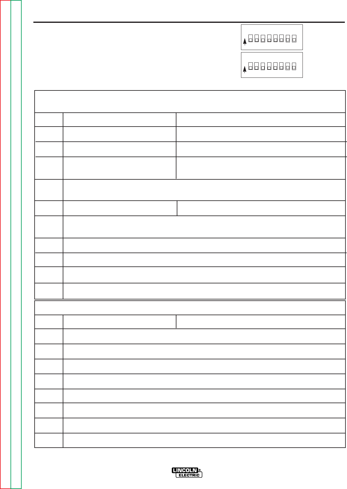
DIP SWITCH SETUP
SETTING DIP SWITCHES IN THE
CONTROL BOX
There are two DIP switch banks on the mother board
of the Control Box. They are labeled S1 and S2 and
are located and oriented as shown in Figure A.3.
Return to Section TOC Return to Section TOC Return to Section TOC Return to Section TOC
Return to Master TOC Return to Master TOC Return to Master TOC Return to Master TOC
FIGURE A.3
S1
ON 1 2 3 4 5 6 7 8
S2
ON 1 2 3 4 5 6 7 8
S1 DIP Switch Bank on Control Box Motherboard (For software version S24004-2 only)
Switch Off On
1 US 4-Step Trigger Logic Euro 4-Step Trigger Logic
2 WFS Display = inches/minute WFS Display = meters/minute
3 Left Display is always preset WFS Left Display is preset WFS when weld current is not flowing
Left Display is actual weld current when weld current is flowing
CC modes override this switch regardless of position. Left Display is always preset weld cur-
rent when weld current is not flowing and actual weld current when weld current is flowing
4 Run-in = Minimum Speed Available Run-in = weld WFS
If any option containing a Run-in setting is connected to the motherboard, it automatically
overrides this switch regardless of position.
5 Spare
6 Acceleration, MSB (Sets acceleration rate for wire drive) see below
7 Acceleration (Sets acceleration rate for wire drive) see below
8 Acceleration, LSB (Sets acceleration rate for wire drive) see below
S2 DIP Switch Bank on Control Box Motherboard (For software version S24004-2 only)
Switch Off On
1 Network Group ID, MSB (Assigns Control Box to a specific group) (Off is factory setting)
2 Network Group ID, LSB (Assigns Control Box to a specific group ) (Off is factory setting)
3 Spare
4 Spare
5 Spare
6 Spare
7 Spare
8 Reserved
Note: the factory shipped settings for all of the S1 and S2 switches is “OFF”.

A-12
INSTALLATION
A-12
POWER WAVE 455/POWER FEED 10
Return to Section TOC Return to Section TOC Return to Section TOC Return to Section TOC
Return to Master TOC Return to Master TOC Return to Master TOC Return to Master TOC
S1 DIP Switch Bank on Control Box Motherboard (For software version S24004-3 & up)
Switch Off On
1
Standard speed gearbox limits adjustable
High speed gearbox limits adjustable
2 WFS Display = inches/minute WFS Display = meters/minute
3 Left Display is always preset WFS Left Display is preset WFS when weld current is not flowing
Left Display is actual weld current when weld current is flowing
CC modes override this switch regardless of position. Left Display is always preset weld cur-
rent when weld current is not flowing and actual weld current when weld current is flowing
4 Run-in = Minimum Speed Available Run-in = weld WFS
If any option containing a Run-in setting is connected to the motherboard, it automatically
overrides this switch regardless of position.
5 Memory change with trigger disabled Memory change with trigger enabled
6 Acceleration, MSB (Sets acceleration rate for wire drive) see below
7 Acceleration (Sets acceleration rate for wire drive) see below
8 Acceleration, LSB (Sets acceleration rate for wire drive) see below
MSB - Most Significant Bit or Byte. This is the bit in a binary number or DIP switch bank that is furthest to the left.
LSB - Least Significant Bit or Byte. This is the bit in a binary number or DIP switch bank that is furthest to the right.
S2 DIP Switch Bank on Control Box Motherboard (For software version S24004-3 & up)
Switch Off On
1 Network Group ID, MSB (Assigns Control Box to a specific group) (Off is factory setting)
2 Network Group ID, LSB (Assigns Control Box to a specific group ) (Off is factory setting)
3 Spare
4 Spare
5 Spare
6 Must be off for normal operation Adjust lower limits
7 Must be off for normal operation Adjust upper limits
8 Must be on for European units only
Note: the factory shipped settings for all of the S1 and S2 switches is “OFF”.

A-13
INSTALLATION
POWER WAVE 455/POWER FEED 10
A-13
S1 DIP Switch Bank on Control Box Motherboard (For software version S24456)
Switch Off On
1
Standard speed gearbox limits adjustable
High speed gearbox limits adjustable
2 WFS Display = inches/minute WFS Display = meters/minute
3 Left Display is always preset WFS Left Display is preset WFS when weld current is not flowing
Left Display is actual weld current when weld current is flowing
CC modes override this switch regardless of position. Left Display is always preset weld cur-
rent when weld current is not flowing and actual weld current when weld current is flowing
4 Run-in = Minimum Speed Available Run-in = weld WFS
If any option containing a Run-in setting is connected to the motherboard, it automatically
overrides this switch regardless of position.
5 Memory change with trigger disabled Memory change with trigger enabled
6 Acceleration, MSB (Sets acceleration rate for wire drive) see below
7 Acceleration (Sets acceleration rate for wire drive) see below
8 Acceleration, LSB (Sets acceleration rate for wire drive) see below
MSB - Most Significant Bit or Byte. This is the bit in a binary number or DIP switch bank that is furthest to the left.
LSB - Least Significant Bit or Byte. This is the bit in a binary number or DIP switch bank that is furthest to the right.
S2 DIP Switch Bank on Control Box Motherboard (For software version S24456)
Switch Off On
1 Network Group ID, MSB (Assigns Control Box to a specific group) (Off is factory setting)
2 Network Group ID, LSB (Assigns Control Box to a specific group ) (Off is factory setting)
3 4-Step Domestic Configuration 4-Step European Configuration
4 Power Feed 10 / Dual Power Feed 11
5 Procedure Change with Trigger “OFF” Procedure Change with Trigger “ON”
6 Set lower limits
7 Set upper limits
8 Must be on for all units (Permits selection of extended modes)
Note: the factory shipped settings for the S2 switches are as follows:
PF-10 (and Dual) Domestic - switches 1-7 “OFF”, 8 “ON” PF-10 (and Dual) European - switches 1,2,4-7 “OFF”, 3,8 “ON”
PF-11 Domestic - switches 1-3,5-7 “OFF”, 4,8 “ON” PF-11 European - switches 1,2,5-7 “OFF”, 3,4,8 “ON”
Note: the factory shipped settings for the S1 switches are as follows:
PF-10 (and Dual) Domestic - All switches “OFF” PF-10 (and Dual) European - switches 1 & 3-8 “OFF”, 2 “ON”
PF-11 Domestic - switches 2-8 “OFF”, 1 “ON” PF-11 European - switches 3-8 “OFF”, 1,2 “ON”
Return to Section TOC Return to Section TOC Return to Section TOC Return to Section TOC
Return to Master TOC Return to Master TOC Return to Master TOC Return to Master TOC
A-14
INSTALLATION
POWER WAVE 455/POWER FEED 10
A-14
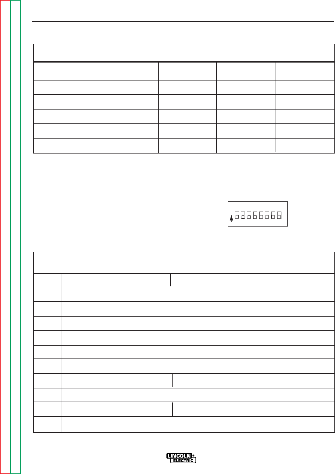
SETTING DIP SWITCHES IN THE WIRE
DRIVE
There is one DIP switch bank on the control board of
the wire drive. It’s labeled S1 and is located and ori-
ented as shown in Figure A.4.
FIGURE A.4
S1 DIP Switch on Wire Drive Control Board (For software version S24029-All & S24467)
Switch Off On
1 Network Group ID, MSB (Assigns Wire Drive to a specific group)
2 Network Group ID, LSB (Assigns Wire Drive to a specific group )
3 Network Feed Head ID, MSB (Assigns feed head number to wire drive)
4 Network Feed Head ID (Assigns feed head number to wire drive)
5 Network Feed Head ID, LSB (Assigns feed head number to wire drive)
6 Spare
7 Electrode Sense Polarity = Positive Electrode Sense Polarity = Negative
Switch position must match polarity of weld cable attached to feed plate.
8 Gear Box Ratio = Low Gear Box Ratio = High
Switch position must match actual gear box ratio of wire drive.
Note: the factory shipped settings for all of the S1 switches is “OFF”.
S1
ON 1 2 3 4 5 6 7 8
DIP SWITCH 6 DIP SWITCH 7 DIP SWITCH 8
Acceleration 1 (slow) Off Off On
Acceleration 2 Off On Off
Acceleration 3 Off On On
Acceleration 4 On Off Off
Acceleration 5 (fast ) (factory setting) Off Off Off
Setting Wire Drive Acceleration Rate Using (All software versions)
DIP Switch S1 on the Control Box Motherboard
Return to Section TOC Return to Section TOC Return to Section TOC Return to Section TOC
Return to Master TOC Return to Master TOC Return to Master TOC Return to Master TOC

A-15
INSTALLATION
POWER WAVE 455/POWER FEED 10
A-15
GUN AND CABLE ASSEMBLIES
GUN AND CABLE ASSEMBLIES WITH
STANDARD CONNECTION
The Power Feed 10 wire feeder is equipped with a
factory installed K1500-2 gun connection kit. This kit
is for guns having a Tweco™ #2-#4 connector. The
Power Feed 10 has been designed to make connect-
ing a variety of guns easily and inexpensively with the
K1500 series of gun connection kits. Gun trigger and
dual procedure lead connections connect to the single
five pin receptacle on the front of the feed head box.
See
Gun Adapters
in
Accessories
section.
GENERAL GUN CONNECTION GUIDELINES
The instructions supplied with the gun and K1500
series gun adapter should be followed when
installing and configuring a gun. What follows are
some general guidelines that are not intended to
cover all guns.
a. Check that the drive rolls and guide tubes
are proper for the electrode size and type
being used. If not, change them per drive
roll installation instructions in the
Operation
section.
b. Lay the cable out straight. Insert the connec-
tor on the welding conductor cable into the
brass conductor block on the front of the wire
drive head. Make sure it is all the way in and
tighten the hand clamp. Keep this connec-
tion clean and bright. Connect the trigger
control cable polarized plug into the mating
five cavity receptacle on the front of the wire
drive unit.
NOTE: For Fast-Mate and European connector style
guns, connect gun to gun connector making sure all
pins and gas tube line up with appropriate holes in
connector. Tighten gun by turning large nut on gun
clockwise.
c. For GMA gun cables with separate gas fit-
tings, connect the 3/16 in. I.D. gas hose
from the wire drive unit to the gun cable
barbed fitting.
d. For water cooled guns, refer to the instruc-
tions supplied with the kit.
GMAW SHIELDING GAS
CYLINDER may explode if damaged.
• Keep cylinder upright and chained to
support.
• Keep cylinder away from areas where it
may be damaged.
• Never lift welder with cylinder attached.
• Never allow welding electrode to touch
cylinder.
• Keep cylinder away from welding or
other live electrical circuits.
BUILDUP OF SHIELDING GAS may
harm health or kill.
• Shut off shielding gas supply when not
in use.
SEE AMERICAN NATIONAL STANDARD Z-49.1,
“SAFETY IN WELDING AND CUTTING” PUB-
LISHED BY THE AMERICAN WELDING
SOCIETY.
-----------------------------------------------------------
Customer must provide a cylinder of shielding gas, a
pressure regulator, a flow control valve, and a hose
from the flow valve to the gas inlet fitting of the wire
drive unit.
Connect a supply hose from the gas cylinder flow
valve outlet to the 5/8-18 female inert gas fitting on
the back panel of the wire drive or, if used, on the
inlet of the Gas Guard Regulator. See
Accessories
section.
WARNING
Return to Section TOC Return to Section TOC Return to Section TOC Return to Section TOC
Return to Master TOC Return to Master TOC Return to Master TOC Return to Master TOC

A-16
INSTALLATION
POWER WAVE 455/POWER FEED 10
A-16
CV/GOUGE PANEL
NOTE: Installation Instructions for the standard
equipment panels will be required only if you have
removed a standard panel and wish to reinstall it.
The CV/Gouge Panel fits into the lower position of
the Control Box.
Installation is as follows:
1. Turn off power.
2. Remove the two screws from the front of the
Control Box panel. Save the screws, discard the
old panel or save for future use.
3. Tilt the new option panel away from the front
opening of the Control Box cabinet. Plug the
electrical connector into the proper connector on
the right side of the main printed circuit board
(12 pin). Make sure the connector latches in
place.
4. Position the panel to the opening, taking care not
to damage the switch connections on the back.
5. Align the screw holes, replace the two screws
and tighten.
OPTIONAL PANELS FOR CONTROL BOX
All optional panels for the control box are described
in the
Accessories
section of this manual.
STANDARD PANEL INSTALLATION
CONTROL/DISPLAY PANEL
NOTE: Installation Instructions for the standard
equipment panels will be required only if you have
removed a standard panel and wish to reinstall it.
The Control/Display Panel fits into the upper or mid-
dle slots of the Control Box, and is used to adjust
WFS, Amps, Voltage, and Trim. It is also the location
of the Status indicator, a diagnostic tool provided for
system troubleshooting.
Installation is as follows:
1. Turn off power.
2. Remove the two screws from the front of the
blank option panel at the location you choose to
install your new panel, (top or middle), of the
Control Box cabinet. Discard the blank panel or
save for future use and save the screws.
3. Tilt the new panel away from the front opening of
the Control Box cabinet. Plug the electrical con-
nector into the proper connector on the right side
of the main printed circuit board (14 pin). Make
sure the connector latches in place.
4. Position the new panel, taking care not to dam-
age the printed circuit boards on the back and
align the screw holes.
5. Replace the two screws and tighten.
Return to Section TOC Return to Section TOC Return to Section TOC Return to Section TOC
Return to Master TOC Return to Master TOC Return to Master TOC Return to Master TOC

OPERATION
POWER WAVE 455/POWER FEED 10
TABLE OF CONTENTS
-OPERATION SECTION-
Operation . . . . . . . . . . . . . . . . . . . . . . . . . . . . . . . . . . . . . . . . . . . . . . . . . . . . . . . . . . . . . . . . . . . . . . . . . Section B
Operating Instructions . . . . . . . . . . . . . . . . . . . . . . . . . . . . . . . . . . . . . . . . . . . . . . . . . . . . . . . . . . . . B-2
Safety Instructions . . . . . . . . . . . . . . . . . . . . . . . . . . . . . . . . . . . . . . . . . . . . . . . . . . . . . . . . . . . . . . B-2
System Description . . . . . . . . . . . . . . . . . . . . . . . . . . . . . . . . . . . . . . . . . . . . . . . . . . . . . . . . . . . . . . B-2
Recommended Equipment . . . . . . . . . . . . . . . . . . . . . . . . . . . . . . . . . . . . . . . . . . . . . . . . . . . . . B-2
Duty Cycle and Welding Capabilities . . . . . . . . . . . . . . . . . . . . . . . . . . . . . . . . . . . . . . . . . . . . . B-3
Limitations . . . . . . . . . . . . . . . . . . . . . . . . . . . . . . . . . . . . . . . . . . . . . . . . . . . . . . . . . . . . . . . . . B-3
Controls and Settings . . . . . . . . . . . . . . . . . . . . . . . . . . . . . . . . . . . . . . . . . . . . . . . . . . . . . . . . . . . . B-3
Power Wave Controls and Status Lights . . . . . . . . . . . . . . . . . . . . . . . . . . . . . . . . . . . . . . . . . . B-3
Power Feed Controls . . . . . . . . . . . . . . . . . . . . . . . . . . . . . . . . . . . . . . . . . . . . . . . . . . . . . . . . . B-4
Display Control Panel . . . . . . . . . . . . . . . . . . . . . . . . . . . . . . . . . . . . . . . . . . . . . . . . . . . . . . . . . B-5
Board Level Adjustments . . . . . . . . . . . . . . . . . . . . . . . . . . . . . . . . . . . . . . . . . . . . . . . . . . . . . . B-6
Weld Mode Descriptions . . . . . . . . . . . . . . . . . . . . . . . . . . . . . . . . . . . . . . . . . . . . . . . . . . . . . . . . . . B-6
Constant Voltage (CV/MIG) . . . . . . . . . . . . . . . . . . . . . . . . . . . . . . . . . . . . . . . . . . . . . . . . . . . . B-6
Arc Gouging . . . . . . . . . . . . . . . . . . . . . . . . . . . . . . . . . . . . . . . . . . . . . . . . . . . . . . . . . . . . . . . . B-6
Electrode Routing . . . . . . . . . . . . . . . . . . . . . . . . . . . . . . . . . . . . . . . . . . . . . . . . . . . . . . . . . . . . . . . B-6
Wire Spindle Replacement . . . . . . . . . . . . . . . . . . . . . . . . . . . . . . . . . . . . . . . . . . . . . . . . . . . . . . . . B-7
Wire Reel Loading - Readi-Reels, Spools or Coils . . . . . . . . . . . . . . . . . . . . . . . . . . . . . . . . . . . . . . B-7
To Mount a 30 lb (14 kg) Readi-Reel Package
(Using the Molded Plastic K363-P Readi-Reel Adapter) (Figure B.4): . . . . . . . . . . . . . . . . . B-7
To Mount 10 to 44 lb (4.5 to 20 kg) Spools [12 in. (300 mm) Diameter]
or 14 lb (6 kg) Innershield Coils (Figure B.4): . . . . . . . . . . . . . . . . . . . . . . . . . . . . . . . . . . . . B-8
To Mount a 50 to 60 lb (22.7 to 27.2 kg) Coil (Using K1504-1 Coil Reel) (Figure B.5): . . . . . . . B-8
Feeding Electrode and Brake Adjustment . . . . . . . . . . . . . . . . . . . . . . . . . . . . . . . . . . . . . . . . . . . . B-9
Drive Roll Kit Installation (KP1505-[]) . . . . . . . . . . . . . . . . . . . . . . . . . . . . . . . . . . . . . . . . . . . . . . . . B-9
Drive Roll Pressure Setting . . . . . . . . . . . . . . . . . . . . . . . . . . . . . . . . . . . . . . . . . . . . . . . . . . . . . . . . B-9
Procedure For Setting Angle of Feedplate . . . . . . . . . . . . . . . . . . . . . . . . . . . . . . . . . . . . . . . . . . . . B-9
Wire Feed Overload Protection . . . . . . . . . . . . . . . . . . . . . . . . . . . . . . . . . . . . . . . . . . . . . . . . . . . . . B-10
SECTION B-1SECTION B-1
Return to Master TOC Return to Master TOC Return to Master TOC Return to Master TOC

B-2
OPERATION
B-2
OPERATING INSTRUCTIONS
Read and understand this entire section of operating
instructions before operating the machine.
SAFETY INSTRUCTIONS
ELECTRIC SHOCK
can kill.
• Do not touch electrically live parts or
electrodes with your skin or wet cloth-
ing.
• Insulate yourself from the work and
ground.
• Always wear dry insulating gloves.
-----------------------------------------------------------
FUMES AND GASES
can be dangerous.
• Keep your head out of fumes.
• Use ventilation or exhaust to remove
fumes from breathing zone.
-----------------------------------------------------------
WELDING SPARKS
can cause fire or explosion.
• Keep flammable material away.
• Do not weld on containers that have
held combustibles.
-----------------------------------------------------------
ARC RAYS
can burn.
• Wear eye, ear, and body protection.
Observe additional Safety Guidelines detailed in
the beginning of this manual.
-----------------------------------------------------------
SYSTEM DESCRIPTION
The Power Wave 455 is a high performance, digitally
controlled inverter welding power source capable of
complex, high-speed waveform control. The Power
Feed 10 is a high performance, digitally controlled,
modular wire feeder. Properly equipped, they can
support the GMAW, GMAW-P, and FCAW processes.
Operating as a system, each component in the sys-
tem has special circuitry to “talk with” the other sys-
tem components, so each component (power source,
wire feeder, electrical accessories) knows what the
other is doing at all times. This shared information
lays the groundwork for a system with superior weld-
ing performance.
The Power Feed 10 is a four driven roll feeder that
operates on 40 VDC input power, and is available
configured in both boom and bench models. In addi-
tion, the Control Box and wire feed unit can also be
purchased separately. The bench model is designed
so that it can easily be converted to a boom feeder.
RECOMMENDED EQUIPMENT
The Power Feed 10 must be used with the Power
Wave 455.
POWER WAVE 455/POWER FEED 10
WARNING
Return to Section TOC Return to Section TOC Return to Section TOC Return to Section TOC
Return to Master TOC Return to Master TOC Return to Master TOC Return to Master TOC
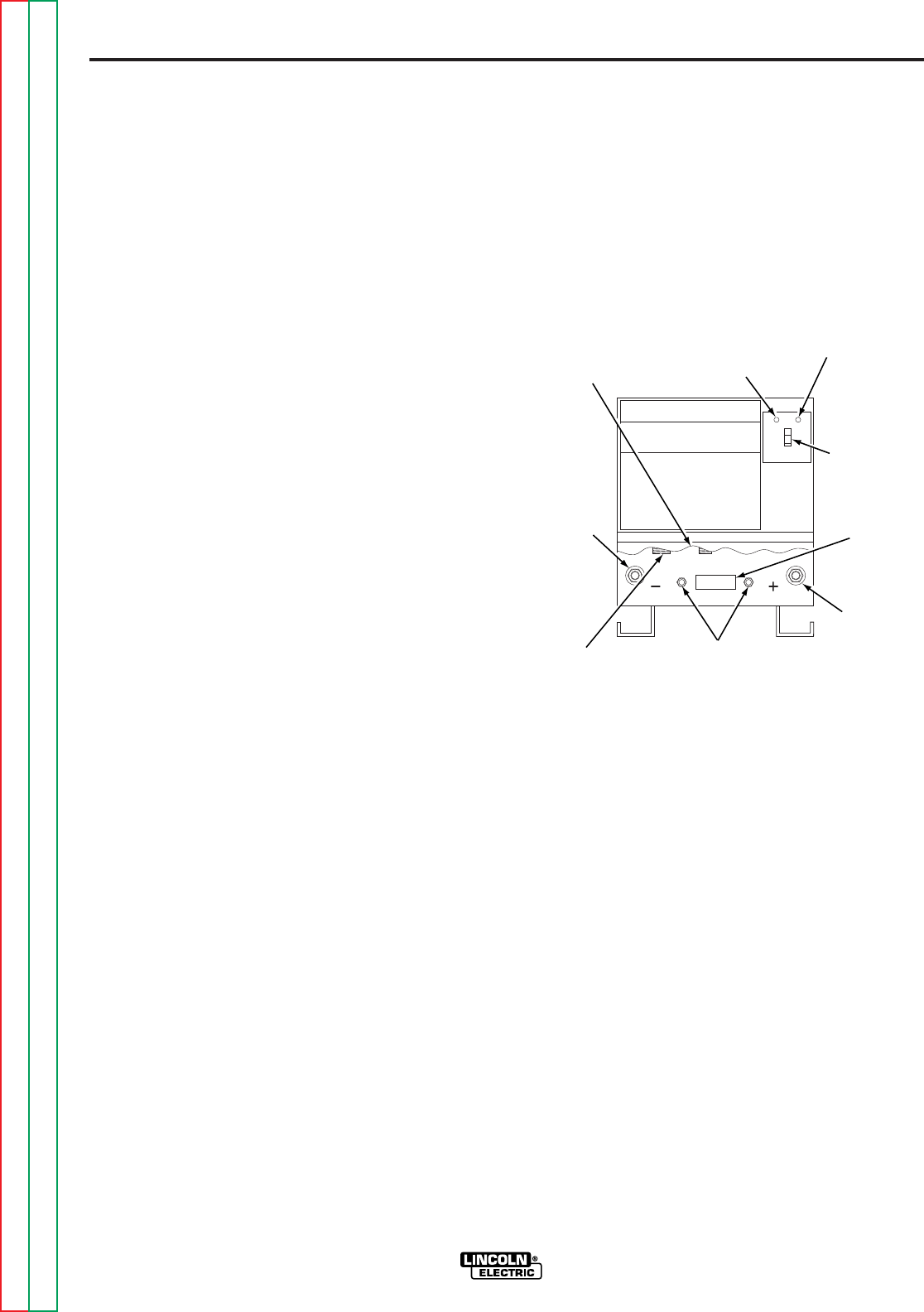
B-3
OPERATION
B-3
DUTY CYCLE AND WELDING
CAPABILITIES
The Power Feed 10 wire feeder is capable of welding
at a 100% duty cycle (continuous welding). The
power source will be the limiting factor in determining
system duty cycle capability.
The Power Wave 455 is rated 450 amps at 38 volts,
100% duty cycle, and 570 amps at 43 volts, 60%
duty cycle. On 50 Hz, the 60% rating is 500 amps at
40 volts, 60% duty cycle. The duty cycle is based
upon a ten minute period. A 60% duty cycle repre-
sents six minutes of welding and four minutes of
idling in a ten minute period.
If the duty cycle is exceeded, a thermostat will shut
off the output until the machine cools to a reasonable
operating temperature.
LIMITATIONS
• The Power Wave is not recommended for process-
es other than those listed.
• The Power Wave can only be used with Power
Feed wire feeders. Other models of Lincoln feed-
ers, or any models of non-Lincoln wire feeders,
cannot be used.
CONTROLS AND SETTINGS
POWER WAVE CONTROLS AND
STATUS LIGHTS
All operator controls and adjustments are located on
the case front of the Power Wave. See Figure B.1.
FIGURE B.1 — POWER WAVE CONTROLS
AND STATUS LIGHTS.
1. POWER SWITCH: Controls input power to the
Power Wave.
2. STATUS LIGHT: A two color light that indicates
system errors. Normal operation is a steady
green light. Error conditions are indicated as fol-
lows:
NOTE: The Power Wave 455 status light will flash
green, and sometimes red and green, for up to one
minute when the Power Wave 455 is first turned on.
This is a normal situation as the machine goes
through a self test at power up.
POWER WAVE 455/POWER FEED 10
HIGH
TEMPERATURE
LIGHT
STATUS
LIGHT
ON/OFF
SWITCH
POSITIVE
TERMINAL
CIRCUIT
BREAKERS
CONTROL
CABLE
CONNECTOR
NEGATIVE
TERMINAL
SPRING LOADED
OUTPUT COVER
(CUTAWAY)
115 VAC
AUXILIARY
RECEPTACLE
Return to Section TOC Return to Section TOC Return to Section TOC Return to Section TOC
Return to Master TOC Return to Master TOC Return to Master TOC Return to Master TOC
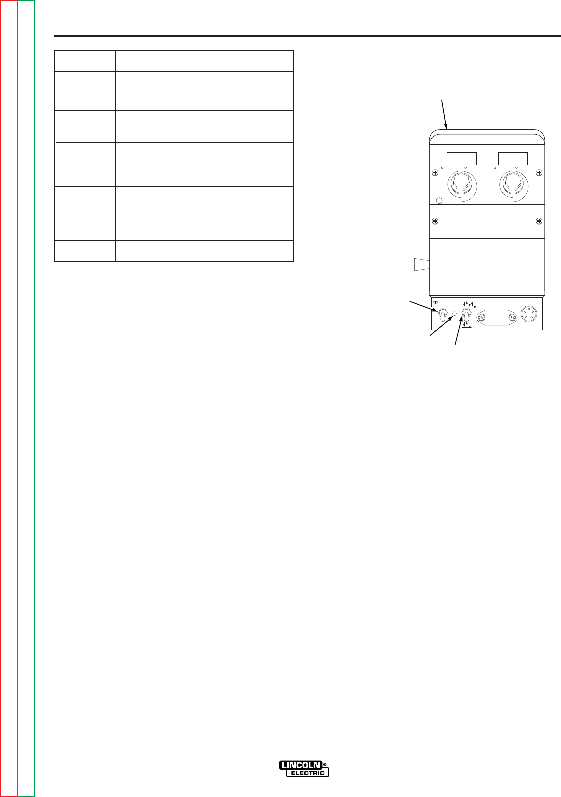
3. HIGH TEMPERATURE LIGHT (thermal overload):
A yellow light that comes on when an over tem-
perature situation occurs. Output is disabled until
the machine cools down. When cool, the light
goes out and output is enabled.
4. 10 AMP WIRE FEEDER CIRCUIT BREAKER:
Protects 40 volt DC wire feeder power supply.
5. 10 AMP AUXILIARY POWER CIRCUIT BREAK-
ER: Protects 115 volt AC receptacle.
POWER FEED CONTROLS
1. 2-STEP/4-STEP SWITCH OPERATION
The Power Feed head unit has a 2-Step/4-Step
switch shown in Figure B.2. This switch has no
effect in CC modes of operation such as stick weld-
ing. When in the 2-step position, the gun trigger func-
tions as follows:
2-Step Operation:
1. Closing the gun trigger initiates gas preflow time
followed by run in speed and strike voltage until
welding current is established.
2. Opening the gun trigger during a weld stops wire
feed and initiates burnback time, followed by gas
postflow time.
Meaning
System OK. Power source communicating
normally with wire feeder and its
components.
Nothing connected to Wire Feeder
Receptacle.
Recoverable system fault. See
Troubleshooting Section.
Non-recoverable system fault. Must turn
power source off, find source of error, and
turn power back on to reset. See
Troubleshooting Section.
See Troubleshooting Section.
B-4
OPERATION
B-4
FIGURE B.2 — WIRE FEEDER CONTROLS.
When the switch is in the 4-step position, the gun
trigger functions as follows:
4-Step Operation (Current interlock):
1. Closing trigger initiates gas preflow time followed
by run in speed and strike voltage until welding
current is established.
2. Once current is established, the trigger may be
released and welding will continue.
3. When the trigger is closed again, welding will
continue but the current interlock function will be
disabled.
4. Releasing the trigger stops the wire feed and ini-
tiates burnback followed by gas postflow.
2. COLD FEED/GAS PURGE SWITCH
The Power Feed head unit has a Cold Feed/Gas
Purge switch. When left untouched, this switch
returns to a center position where no action results.
POWER WAVE 455/POWER FEED 10
Light
Condition
Steady Green
Blinking
Green
Alternating
Green and
Red
Steady Red
Blinking Red
COLDFEED
STATUS 4-STEP
2-STEP
CONTROL BOX
(SHOWN ATTACHED
TO WIRE FEEDER)
2. COLD FEED/
GAS PURGE
SWITCH
3. STATUS
LIGHT 1. 2-STEP/
4-STEP
SWITCH
Return to Section TOC Return to Section TOC Return to Section TOC Return to Section TOC
Return to Master TOC Return to Master TOC Return to Master TOC Return to Master TOC

B-5
OPERATION
B-5
Cold feed function:
When this switch is held in the up position, the unit
automatically feeds wire, but does not activate output
to the power source or gas solenoid. The speed of
this cold feed is factory preset to 200 IPM. It can be
adjusted while the switch is held up, by rotating the
WFS encoder knob on the Control Box. Note that
this cold feed speed is independent of WFS or run in
speeds. When the cold feed switch is released, the
cold feed value is memorized for the next time cold
feed is activated.
Gas purge function:
When this switch is held in the down position only the
gas solenoid valve is energized.
3. STATUS LIGHT
A two color light that indicates system errors. Normal
operation is a steady green light.
DISPLAY CONTROL PANEL
The Display Control panel is the main input to the
system. From it, the operator can control WFS,
amps, voltage, and trim depending on the active weld
mode. It is also the location of the Status
indicator, a multicolored diagnostic LED (see
Troubleshooting
section). Refer to Figure B.3.
FIGURE B.3 — CONTROL BOX.
1. Indicator Lights:
Indicates either WFS or AMPS for the left display,
and VOLTS or TRIM for the right display.
2. Displays:
Two extra bright, 3 1/2 digit, red LED displays. The
values of the active parameters are displayed, as
defined by their associated indicators. The left dis-
play is for WFS or Amps, while the right display is for
voltage or trim.
3. Left Encoder-Wire Feed Speed or Output Amps:
The left encoder is used to adjust the parameters for
either wire feed speed or output amps, dependent
upon the process and weld mode being used.
Rotating the encoder knob CCW decreases the num-
ber value, while rotating the knob CW increases the
number value. The ranges and limits are as follows:
WFS - Low Range: 50 to 800 IPM (1.25 to 19.99 MPM)
High Range: 75 to 1200 IPM (2.0 to 30.5 MPM)
AMPS - Limited by the power source based on mode
and process.
4. Right Encoder - Trim or Output Volts:
The right encoder operates in the same manner as
the left except that either output Volts or Trim is
adjusted. The ranges and limits are as follows:
VOLTS - 00.0 to 99.9 volts, limited by power source
based on mode and process.
TRIM - 0.50 to 1.50, nominal value is 1.00
When not welding (no output current flow) the displays
reflect the preset values. During welding (output cur-
rent flowing) the displays depict actual values. These
actual values are held for a period of five seconds after
welding (output current) ceases. This hold feature is
canceled if a trigger pull or encoder adjustment occurs
during the hold time. The actual value displayed is
dependent upon the weld mode and process being
used.
5. Status light:
A two color light that indicates system errors. Normal
operation is a steady green light.
POWER WAVE 455/POWER FEED 10
GOUGE
STATUS
WFS AMPS VOLTS TRIM
A V T
CV/MIG
WELD MODE
m
1. INDICATOR
LIGHTS 2. DISPLAYS
1. INDICATOR
LIGHTS
3. WFS/
AMPS
ENCODER
5. STATUS
LIGHT
6. CV/GOUGE PANEL
BLANK PANEL
DISPLAY
CONTROL
PANEL
4. VOLTS/
TRIM
ENCODER
Return to Section TOC Return to Section TOC Return to Section TOC Return to Section TOC
Return to Master TOC Return to Master TOC Return to Master TOC Return to Master TOC

B-6
OPERATION
B-6
6. CV/GOUGE PANEL
The CV/Gouge Panel provides a fixed toggle switch
selection of two power source modes. The upper
position selects the generic CV/MIG mode from the
power source while the lower position selects the
GOUGE mode.
OPTIONAL PANELS
A number of Optional Features are available for use
with the Power Feed 10. Some Installation informa-
tion is provided in the
ACCESSORIES
section,
REFER TO THE INSTRUCTIONS THAT COME
WITH EACH KIT FOR DETAILED INFORMATION
REGARDING INSTALLATION.
BOARD LEVEL ADJUSTMENTS
The control box motherboard provides the capability
to adjust some basic parameters as follows.
BURNBACK
The BURNBACK trimmer (R5) is provided as a basic
adjustment for burnback time. The range is 0.0 to
0.25 seconds, CCW limit is minimum, CW limit is
maximum. This value is overridden by any option
with the ability to independently adjust burnback.
ACCELERATION
See
DIP Switch setup
in the
Installation
section.
RUN IN
See
DIP Switch setup
in the
Installation
section.
WELD MODE DESCRIPTIONS
CONSTANT VOLTAGE (CV/MIG)
For each wire feed speed, a corresponding voltage is
preprogrammed into the machine through special
softwares at the factory. This preprogrammed volt-
age is the best average voltage for the procedure at
the given wire feed speed. If the wire feed speed is
changed on the wire feeder, the voltage automatical-
ly changes with it.
In some cases, the operator may want to change the
preprogrammed voltages; for example, to compen-
sate for cable and fixture voltage drops. The preset
voltages can be adjusted on the wire feeder’s voltage
display. When a change is made to the voltage at
one wire feed speed, this change is applied to all
other wire feed speed settings. For example, if the
operator turns up the voltage by 10 percent, the
machine automatically increases the preset voltages
at all the other wire feed speeds by 10 percent. The
preset voltage, programmed at the factory, may be
changed with the wire feeder VOLTS adjustment.
ARC GOUGING
Arc gouging can be performed by choosing the arc
gouging weld mode. Doing so automatically ener-
gizes the output terminals on the Power Wave, mak-
ing the power source immediately ready to gouge.
The output current is set by the AMPS control on the
Power Weld wire feeder. The VOLTS/TRIM adjust-
ment has no effect in this mode.
The ARC CONTROL adjusts the arc force.
Increasing the ARC CONTROL setting increases the
arc force, making the arc more harsh but less likely
to stick. Decreasing the ARC CONTROL setting
decreases the arc force, making the arc softer and
smoother.
ELECTRODE ROUTING
The electrode supply may be either from reels,
Readi-Reels, spools, or bulk packaged drums or
reels. Observe the following precautions:
a. The electrode must be routed to the wire
drive unit so that the bends in the wire are at
a minimum, and also that the force required
to pull the wire from the reel into the wire
drive unit is kept at a minimum.
b. The electrode is “hot” when the gun trigger is
pressed and must be insulated from the
boom and structure.
c. If more than one wire feed unit shares the
same boom and are not sharing the some
power source output stud, their wire and
reels must be insulated from each other as
well as insulated from their mounting struc-
ture.
POWER WAVE 455/POWER FEED 10
Return to Section TOC Return to Section TOC Return to Section TOC Return to Section TOC
Return to Master TOC Return to Master TOC Return to Master TOC Return to Master TOC
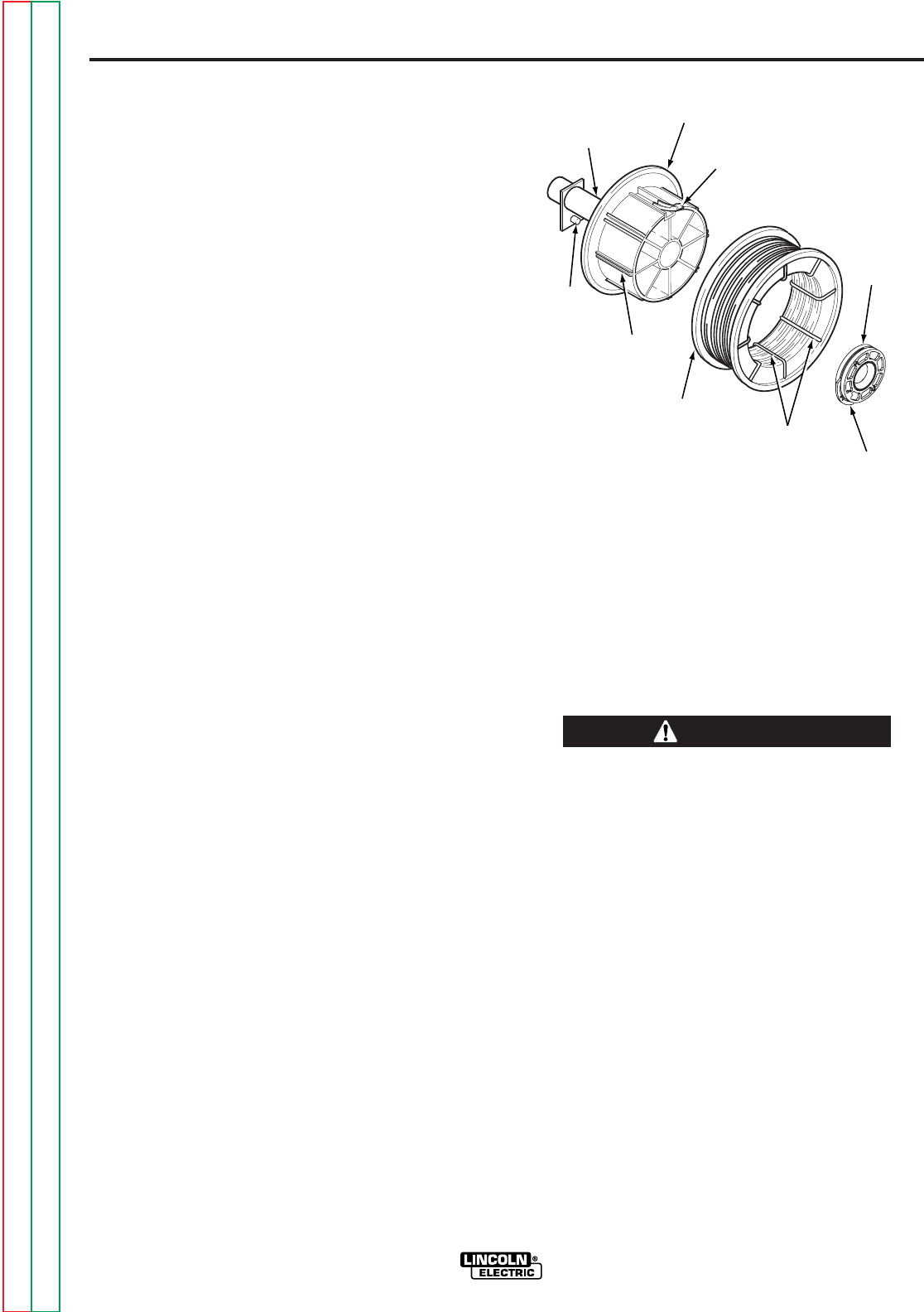
B-7
OPERATION
B-7
WIRE SPINDLE PLACEMENT
The reel stand provides two mounting locations for
the 2 inch diameter wire reel spindle to accommo-
date various reel sizes. Each mounting location con-
sists of a tube in the center of the reel stand, and a
locating pin on the right side (viewed from the front)
of the reel stand. The bolt, used with a plain washer
and lock washer, slides through the tube from the left
side of the reel stand. The large plain washer is
placed between the wire spindle hub and the reel
stand. The bolt should be threaded into the wire
spindle such that the locating pin aligns with the
largest of the three holes (the hole that is not
recessed) in the back side of the wire spindle base.
The upper location must be used for 50 to 60 lb
Readi-Reels, spools and coils.
For smaller coils (44 lb, 30 lb, 10 lb, etc.), the spindle
can be placed in either the upper or lower location.
The goal is to make the wire path from the coil to the
incoming wire guide as straight as possible. This will
optimize wire feeding performance.
WIRE REEL LOADING -
READI-REELS, SPOOLS
OR COILS
TO MOUNT A 30 LB (14 KG) READI-
REEL PACKAGE (USING THE MOLDED
PLASTIC K363-P READI-REEL
ADAPTER) (FIGURE B.4):
The spindle should be located in the LOWER mount-
ing hole.
1. Depress the release bar on the retaining collar
and remove it from the spindle.
2. Place the adapter on the spindle.
3. Re-install the retaining collar. Make sure that the
release bar “pops up” and that the collar retainers
fully engage the retaining groove on the spindle.
4. Rotate the spindle and adapter so the retaining
spring is at the 12 o'clock position.
5. Position the Readi-Reel so that it will rotate in a
direction when feeding so as to be de-reeled from
the bottom of the coil.
FIGURE B.4 — READI-REEL MOUNTING.
6. Set one of the Readi-Reel inside cage wires on
the slot in the retaining spring tab.
7. Lower the Readi-Reel to depress the retaining
spring and align the other inside cage wires with
the grooves in the molded adapter.
8. Slide cage all the way onto the adapter until the
retaining spring “pops up” fully.
Check to be sure the retaining spring has fully
returned to the locking position and has SECURELY
locked the Readi-Reel cage in place. Retaining
spring must rest on the cage, not the welding elec-
trode.
-----------------------------------------------------------
9. To remove Readi-Reel from adapter, depress
retaining spring tab with thumb while pulling the
Readi-Reel cage from the molded adapter with
both hands. Do not remove adapter from spindle.
POWER WAVE 455/POWER FEED 10
CAUTION
2 IN. O.D.
SPINDLE
ADAPTER
RETAINING
SPRING
BRAKE
HOLDING
PIN GROOVES
READI-REEL
INSIDE
CAGE
WIRES RELEASE
BAR
RETAINING
COLLAR
Return to Section TOC Return to Section TOC Return to Section TOC Return to Section TOC
Return to Master TOC Return to Master TOC Return to Master TOC Return to Master TOC
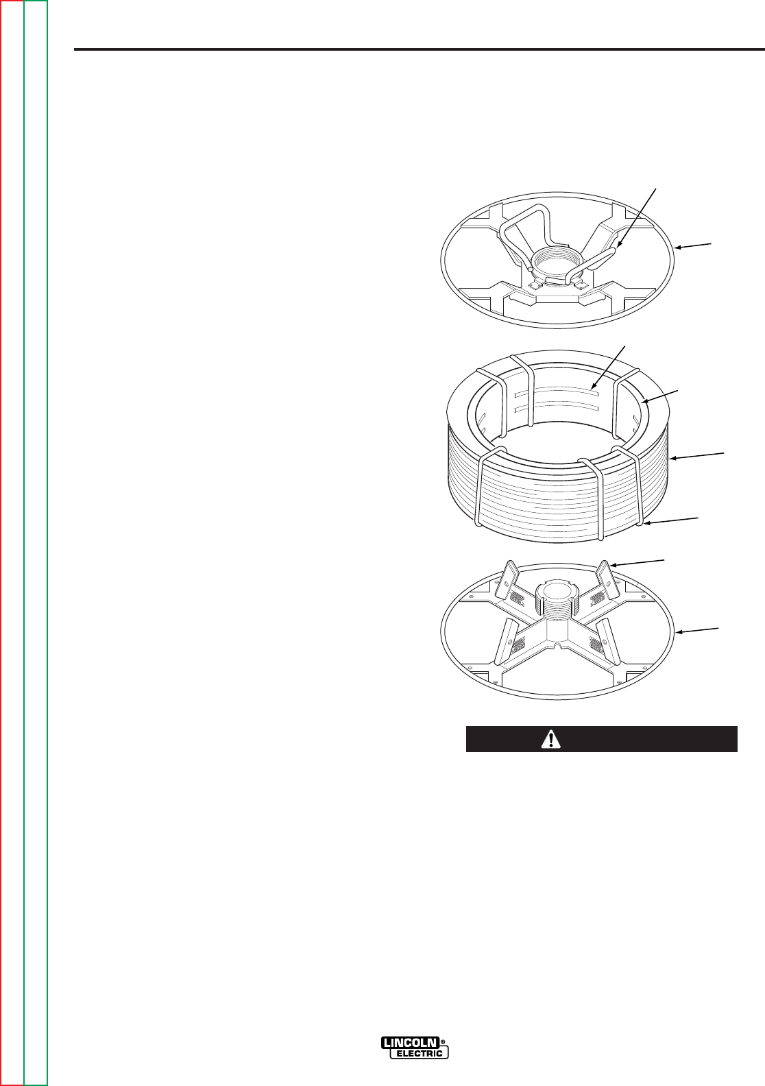
B-8
OPERATION
B-8
TO MOUNT 10 TO 44 LB (4.5 TO 20
KG) SPOOLS [12 IN. (300 MM)
DIAMETER] OR 14 LB (6 KG)
INNERSHIELD COILS (FIGURE B.4):
The spindle should be located in the LOWER
mounting hole.
(For 8 in. (200 mm) spools, a K468 spindle adapter
must first be slipped onto spindle.)
(For 13 to 14 lb (6 kg) Innershield coils, a K435 coil
adapter must be used).
1. Depress the release bar on the retaining collar
and remove it from the spindle.
2. Place the spool on the spindle making certain the
spindle brake pin enters one of the holes in the
back side of the spool. Be certain the wire comes
off the reel in a direction so as to de-reel from the
bottom of the coil.
3. Re-install the retaining collar. Make sure that the
release bar “pops up” and that the collar retainers
fully engage the retaining groove on the spindle.
TO MOUNT A 50 TO 60 LB (22.7 TO
27.2 KG) COIL (USING K1504-1 COIL
REEL) (FIGURE B.5):
NOTE: (For 50 to 60 lb Readi-Reels a K438
Readi-Reel adapter must be used).
The spindle must be located in the UPPER mounting
hole.
1. With the K1504-1 coil reel mounted on to the 2 in.
(51 mm) spindle (or with reel laying flat on the
floor) loosen the spinner nut and remove the reel
cover. See Figure B.5.
2. Before cutting the tie wires, place the coil of elec-
trode on the reel so it unwinds from the bottom as
the reel rotates. The slots in the cardboard liner
should align over the spring loaded arms.
3. Tighten the spinner nut against the reel cover as
much as possible by hand using the reel cover
spokes for leverage. DO NOT hammer on the
spinner nut arms.
4. Cut and remove only the tie wire holding the free
end of the coil. Hook the free end around the rim
of the reel cover and secure it by wrapping it
around. Cut and remove the remaining tie wires.
FIGURE B.5 — K1504-1 COIL REEL.
Always be sure the free end of the coil is securely
held while the tie wires are being cut and until the
wire is feeding through the drive rolls. Failure to do
this will result in “backlashing” of the coil, which may
tangle the wire. A tangled coil will not feed so it must
either be untangled or discarded.
-----------------------------------------------------------
5. Be sure the coil reel is engaged with the spindle
brake pin and the release bar on the retaining col-
lar “pops up” and that the collar retainers fully
engage the retaining groove on the spindle.
POWER WAVE 455/POWER FEED 10
CAUTION
SPINNER NUT
COVER
PLATE
SLOTS
CARDBOARD
COIL LINER
COIL
TIE WIRE
SPRING
LOADED ARM
REEL
Return to Section TOC Return to Section TOC Return to Section TOC Return to Section TOC
Return to Master TOC Return to Master TOC Return to Master TOC Return to Master TOC

B-9
OPERATION
B-9
FEEDING ELECTRODE AND
BRAKE ADJUSTMENT
1. Turn the reel or spool until the free end of the
electrode is accessible.
2. While tightly holding the electrode, cut off the bent
end and straighten the first 6 in. (150 mm). Cut
off the first 1 in. (25 mm). (If the electrode is not
properly straightened, it may not feed or may jam
causing a “birdnest”.)
3. Insert the free end through the incoming guide.
4. Press the Cold Feed Switch while pushing the
electrode into the incoming wire guide.
If feeding with the Gun Trigger, the electrode and
wire drive may be electrically “HOT”.
-----------------------------------------------------------
5. Feed the electrode through the gun.
6. Adjust the brake tension with the thumbscrew on
the spindle hub, until the reel turns freely but with
little or no overrun when wire feeding is stopped.
Do not overtighten.
DRIVE ROLL KIT INSTALLATION
(KP1505-[])
1. Turn off welding power source.
2. Pull open pressure door to expose rolls and wire
guides.
3. Remove outer wire guide by turning knurled
thumb screws counterclockwise to unscrew them
from Feedplate.
4. Remove the drive rolls, if any are installed, by
pulling straight off the shaft. Remove the inner
guide.
5. Insert the inner wire guide, groove side out, over
the two locating pins in the feedplate.
6. Install each drive roll by pushing over the shaft
until it butts up against the locating shoulder on
the drive roll shaft. (Do not exceed maximum wire
size rating of the wire drive).
7. Install the outer wire guide by sliding over the
locating pins and tightening in place.
8. Engage the upper drive rolls if they are in the
“open” position and close pressure door.
To set drive roll pressure, see
Drive Roll Pressure
Setting.
DRIVE ROLL PRESSURE
SETTING
The Power Feed 10 pressure is factory pre-set to
about position “2” as shown on the pressure indicator
on the front of the feedplate door. This is an approxi-
mate setting.
The optimum drive roll pressure varies with type of
wire, surface condition, lubrication, and hardness.
Too much pressure could cause “birdnesting”, but
too little pressure could cause wire feed slippage with
load and/or acceleration. The optimum drive roll set-
ting can be determined as follows:
1. Press end of gun against a solid object that is
electrically isolated from the welder output and
press the gun trigger for several seconds.
2. If the wire “birdnests”, jams, or breaks at the drive
roll, the drive roll pressure is too great. Back the
pressure setting out one turn, run new wire
through the gun, and repeat above steps.
3. If the only result is drive roll slippage, disengage
the gun, pull the gun cable forward about 6 in.
(150 mm). There should be a slight waviness in
the exposed wire. If there is no waviness, the
pressure is too low. Increase the pressure setting
one turn, reconnect the gun, tighten locking clamp
and repeat the above steps.
PROCEDURE FOR SETTING
ANGLE OF FEEDPLATE
1. Loosen the clamping collar screw using a 3/16 in.
Allen wrench. The clamping collar screw is
accessed from the bottom of the feedplate. It is
the screw which is perpendicular to the feeding
direction.
2. Rotate feedplate to the desired angle and tighten
clamping collar screw.
POWER WAVE 455/POWER FEED 10
WARNING
Return to Section TOC Return to Section TOC Return to Section TOC Return to Section TOC
Return to Master TOC Return to Master TOC Return to Master TOC Return to Master TOC

B-10
OPERATION
B-10
WIRE FEED OVERLOAD
PROTECTION
The wire drive has solid-state overload protection of
the wire drive motor. If the wire drive motor becomes
overloaded for an extended period of time the wire
drive will issue a shutdown command to the Control
Box and force its STATUS light to blink between
green and red. The Control Box turns off the power
source, wire feed and gas solenoid. The status light
on the wire drive will continue to blink between green
and red for about 30 seconds before the wire drive
will automatically reset. At that time, the wire drive
will issue a shutdown over command to the Control
Box that will return the system to normal operation.
The wire drive will force its STATUS light to solid
green.
Overloads can result from improper tip size, liner,
drive rolls, or guide tubes, obstructions or bends in
the gun cable, feeding wire that is larger than the
rated capacity of the feeder or any other factors that
would impede normal wire feeding.
POWER WAVE 455/POWER FEED 10
Return to Section TOC Return to Section TOC Return to Section TOC Return to Section TOC
Return to Master TOC Return to Master TOC Return to Master TOC Return to Master TOC

ACCESSORIES
POWER WAVE 455/POWER FEED 10
SECTION C-1SECTION C-1
TABLE OF CONTENTS
-ACCESSORIES SECTION-
Accessories . . . . . . . . . . . . . . . . . . . . . . . . . . . . . . . . . . . . . . . . . . . . . . . . . . . . . . . . . . . . . . . . . . . . . . . Section C
General . . . . . . . . . . . . . . . . . . . . . . . . . . . . . . . . . . . . . . . . . . . . . . . . . . . . . . . . . . . . . . . . . . . . . . . C-2
Power Wave Options and Accessories . . . . . . . . . . . . . . . . . . . . . . . . . . . . . . . . . . . . . . . . . . . . . . . C-3
Factory Installed . . . . . . . . . . . . . . . . . . . . . . . . . . . . . . . . . . . . . . . . . . . . . . . . . . . . . . . . . . . . . C-3
Field Installed . . . . . . . . . . . . . . . . . . . . . . . . . . . . . . . . . . . . . . . . . . . . . . . . . . . . . . . . . . . . . . . C-3
Wire Feeder Options and Accessories . . . . . . . . . . . . . . . . . . . . . . . . . . . . . . . . . . . . . . . . . . . . . . . C-3
Drive Roll and Guide Tube Kits . . . . . . . . . . . . . . . . . . . . . . . . . . . . . . . . . . . . . . . . . . . . . . . . . C-3
Input Cable Assemblies . . . . . . . . . . . . . . . . . . . . . . . . . . . . . . . . . . . . . . . . . . . . . . . . . . . . . . . C-4
Cable Receptacles . . . . . . . . . . . . . . . . . . . . . . . . . . . . . . . . . . . . . . . . . . . . . . . . . . . . . . . . . . . C-4
Reel Adapters . . . . . . . . . . . . . . . . . . . . . . . . . . . . . . . . . . . . . . . . . . . . . . . . . . . . . . . . . . . . . . . C-6
Guns and Gun Adapters . . . . . . . . . . . . . . . . . . . . . . . . . . . . . . . . . . . . . . . . . . . . . . . . . . . . . . . C-6
Conduit Adapters . . . . . . . . . . . . . . . . . . . . . . . . . . . . . . . . . . . . . . . . . . . . . . . . . . . . . . . . . . . . C-7
Dual Procedure Switch Options . . . . . . . . . . . . . . . . . . . . . . . . . . . . . . . . . . . . . . . . . . . . . . . . . C-8
Gas and Water Kits . . . . . . . . . . . . . . . . . . . . . . . . . . . . . . . . . . . . . . . . . . . . . . . . . . . . . . . . . . C-8
Chassis Options . . . . . . . . . . . . . . . . . . . . . . . . . . . . . . . . . . . . . . . . . . . . . . . . . . . . . . . . . . . . . C-8
Description and Installation of Optional Control Box Panels . . . . . . . . . . . . . . . . . . . . . . . . . . . C-9
Return to Master TOC Return to Master TOC Return to Master TOC Return to Master TOC

C-2
ACCESSORIES
C-2
GENERAL
The following is a list of the accessories that can be
used with the Power Feed 10 wire feeder and the
Power Wave 455. A description of each item is given
later in the section.
POWER WAVE 455/POWER FEED 10
K1570-1 DUAL CYLINDER UNDERCARRIAGE
KP1505 Series DRIVE ROLL AND GUIDE TUBE KITS
K1543 INPUT CABLE ASSEMBLY (CONTROL CABLE ONLY)
K1544 INPUT CABLE ASSEMBLY
K1548-1 RECEPTACLE KIT (INPUT AND OUTPUT)
K162h WIRE SPINDLE ADAPTER
K1504-1 COIL ADAPTER
K435 COIL ADAPTER
K363P READI-REEL ADAPTER
K438 READI-REAL ADAPTER
K489-7 FAST-MATE™ GUN ADAPTERS
K489-2
K466-10 CONNECTOR KIT
K471-21,-22, -23 MAGNUM 400 WELDING GUNS
K497-20, -21 MAGNUM 200 WELDING GUNS
K613-7 MAGNUM 550 WELDING GUN CONNECTOR KIT
K556 (250XA) LINCOLN FUME EXTRACTION GUNS
K556 (400XA)
K206
K289
K309
K489-2 FAST-MATE™ ADAPTER KIT
K1500-1 LINCOLN INNERSHEILD GUN STANDARD CONNECTION
K1500-2 TWECO™ #2-#4 CONNECTION
K1500-3 TWECO™ #5 CONNECTION
K1500-4 MILLER CONNECTION
K1546-1 CONDUIT ADAPTER
K1546-2 CONDUIT ADAPTER
K683-1 DUAL PROCEDURE SWITCH
K683-3 DUAL PROCEDURE SWITCH
K590-5 WATER CONNECTION KIT (FOR DRIVE ONLY)
K1536-1 WATER FLOW SENSOR KIT
K659-1 GAS GUARD REGULATOR
K1557-1 SWIVEL MOUNT
K1556-1 LIGHT DUTY CASTER KIT
K1574-1 SECURITY DOOR (LARGE)
K1555-1 INSULATED LIFT HOOK
K1542-5 DUAL PROCEDURE PANEL
K1542-6 “M” PANEL
K1546-7 MX PANEL (LARGE)
K1542-8 MSP PANEL (LARGE)
K1542-9 DUAL PROCEDURE / MEMORY PANEL (SMALL)
K1542-11 MX2 PANEL (LARGE)
K1542-12 MSP2 PANEL (LARGE)
TABLE C.1 — POWER FEED 10 AND POWER WAVE 455 ACCESSORIES.
Return to Section TOC Return to Section TOC Return to Section TOC Return to Section TOC
Return to Master TOC Return to Master TOC Return to Master TOC Return to Master TOC

C-3
ACCESSORIES
C-3
POWER WAVE OPTIONS AND
ACCESSORIES
The following is a list of available Power Wave
options.
FACTORY INSTALLED
There are no factory installed options available for
the Power Wave machines.
FIELD INSTALLED
The following options/accessories are available for
your Power Wave from your local Lincoln Distributor.
K1570-1 DUAL CYLINDER UNDERCARRIAGE
This is a platform undercarriage for mounting up to
two gas cylinders at the rear of the welder.
WIRE FEEDER OPTIONS AND
ACCESSORIES
The following is a list of available Wire Feeder
options.
DRIVE ROLL AND GUIDE TUBE KITS
POWER WAVE 455/POWER FEED 10
TABLE C.2 — DRIVE ROLL AND GUIDE TUBE KITS.
Wire Size 4-Roll
Drive
(4-Driven)
Solid Steel Electrode
in. mm
0.023 - 0.025 0.6 KP1505 - 030S
0.030 0.8 KP1505 - 030S
0.035 0.9 KP1505 - 035S
0.040 1.0 KP1505 - 045S
0.045 1.2 KP1505 - 045S
0.052 1.4 KP1505 - 052S
1/16 1.6 KP1505 - 1/16S
5/64 2.0 KP1505 - 5/64
3/32 2.4 KP1505 - 3/32
Cored Electrode
in. mm
0.030 0.8 KP1505 - 035C
0.035 0.9 KP1505 - 035C
0.040 1.0 KP1505 - 045C
0.045 1.2 KP1505 - 045C
0.052 1.4 KP1505 - 052C
1/16 1.6 KP1505 - 1/16C
0.068 1.7 KP1505 - 068
5/64 2.0 KP1505 - 5/64
3/32 2.4 KP1505 - 3/32
7/64 Hard Facing,smooth U groove 2.8 KP1505 - 7/64H
7/64 2.8 KP1505 - 7/64
0.120 3.0 KP1505 - 120
Aluminum Wire
.035" (0.9 mm) Aluminum KP1507-035A
.040" (1.0 mm) Aluminum KP1507-040A
3/64" (1.2 mm) Aluminum KP1507-3/64A
1/16" (1.6 mm) Aluminum KP1507-1/16A
3/32” (2.2 mm) Aluminum KP1507-3/32A
Return to Section TOC Return to Section TOC Return to Section TOC Return to Section TOC
Return to Master TOC Return to Master TOC Return to Master TOC Return to Master TOC

C-4
ACCESSORIES
C-4
POWER WAVE 455/POWER FEED 10
INPUT CABLE ASSEMBLIES
K1543 (Control Cable Only) - Consists of a 5-con-
ductor control cable with a 5-pin control cable plug,
without electrode cable, and is available in lengths of
10 ft, 15 ft, 20 ft, 50 ft, and 100 ft.
K1544 - Consists of a 5-conductor control cable with
a 5-pin control cable plug and a 3/0 electrode cable.
It is rated at 600 amps, 60% duty cycle and is avail-
able in lengths of 10 ft,15 ft, 20 ft, and 50 ft.
With input power disconnected from the power
source, install the input cable by performing the
following:
CABLE RECEPTACLES
K1548-1 RECEPTACLE KIT (INPUT AND
OUTPUT)
This kit contains the contents of both the K1549-1
and K1550-1 kits. Refer to the instructions for each,
below.
RECEPTACLE (OUTPUT)
Optional Output Connector installation into the
Control Box cabinet and/or into the feed head
enclosure.
Control Box Cabinet Procedure
1. Turn off power.
2. Remove the screws from the front of the lower
and middle option panels of the Control Box.
3. Tilt the option panels away from the front open-
ing of the Control Box cabinet. If the option panel
has an electrical connector, disconnect it from
the main printed circuit board (note connection
point for re-connection later). Remove the option
panel and set aside.
4. Remove the plastic plug (black) from the left hole
in the bottom of the Control Box cabinet and
store it in the bottom of the Control Box cabinet
for future use, should the Optional Output
Connector be removed.
5. Place the Optional Output Connector
(Amphenol) through the hole opened by the pre-
vious step (place from the inside, out). Rotate
the Optional Output Connector so its aligning
key is positioned to the front of the Control Box
cabinet. Fasten the Optional Output Connector
to the bottom wall of the Control Box cabinet with
the four screws provided.
6. Secure the choke (large circular component of
the Optional Output Connector) by inserting its
leads into the white nylon clip located near the
Optional Output Connector on the back wall of
the Control Box cabinet. Insert the choke leads
only.
7. The Optional Output Connector has two internal
connectors, a four pin, and a single lead connec-
tor. Connect the four pin connector to the
unused four pin connector on the main printed
circuit board. Connect the single lead connector
to a similar connector found on a lead nearby
that branches out of the Control Box wiring har-
ness.
8. Re-install the lower and middle option panels by
reversing the removal process. While re-
installing the option panels, ensure clearance
between Optional Output Connector compo-
nents, Control Box wiring harness, and option
panel harness (if any).
Return to Section TOC Return to Section TOC Return to Section TOC Return to Section TOC
Return to Master TOC Return to Master TOC Return to Master TOC Return to Master TOC

C-5
ACCESSORIES
C-5
POWER WAVE 455/POWER FEED 10
Feed Head Enclosure Procedure
1. Turn power off.
2. Remove the Feed Head rear access door. The
Feed Head cover can be removed to aid installa-
tion, but is not required.
3. Remove the plastic plug (black) from the hole at
the right rear of the Feed Head and store it in the
left side of the Feed Head rear compartment for
future use, should the Optional Output
Connector be removed.
4. Disconnect a printed circuit board connector,
located at the bottom right corner of the printed
circuit board, and position it to the left so as to
provide clear access to the lower right corner of
the Feed Head enclosure.
5. Place the Optional Output Connector
(Amphenol) through the hole opened by the two
previous steps (place from the inside, out).
Rotate the Optional Output Connector so its
aligning key is positioned to the top of the Feed
Head enclosure. Fasten the Optional Output
Connector to the back wall of the Control Box
cabinet with the four screws provided.
6. Secure the choke (large circular component of
the Optional Output Connector) by inserting its
leads into the white nylon clip located near the
Optional Output Connector on the floor of the
Feed Head. Insert the long choke leads rather
than the short leads that run between the choke
and the Output Connector. Insert the choke
leads only.
7. The Optional Output Connector has two internal
connectors, a four pin, and a single lead connec-
tor. Connect the four pin connector to the
unused four pin connector on the printed circuit
board. Connect the single lead connector to a
similar connector found on a lead nearby that
branches out of the Feed Head wiring harness.
8. Reconnect the printed circuit board connector
that was disconnected earlier.
9. Replace the rear access door and Feed Head
cover if removed.
RECEPTACLE (INPUT)
Power Feed Wire Feeder Optional Input
Connector Installation into the Control Box
Cabinet and Conversion to Fixture Wire Feeder
1. Turn off power.
2. Remove the screws from the front of the lower
and middle option panels of the Control Box cab-
inet.
3. Tilt the option panels away from the front open-
ing of the Control Box cabinet. If the option panel
has an electrical connector, disconnect it from
the main printed circuit board (note connection
point for re-connection later). Remove the option
panel and set aside.
4. Disconnect the connector located at the back
wall of the Control Box cabinet.
5. Loosen (do not remove) the four screws located
on the back wall of the Control Box cabinet.
6. Lift Control Box cabinet off of the four screws
loosened above and set on a work surface. Re-
tighten the four screws to secure for future use.
7. Remove the plastic plug (black) from the right
hole in the bottom wall of the Control Box cabi-
net and insert it into the hole in the front of the
Feed Head.
8. Place the Optional Input Connector (Amphenol)
through the hole opened by the previous step
(place from the inside, out). Rotate the Optional
Input Connector so it’s aligning key is positioned
to the front of the Control Box cabinet. Fasten the
Optional Input Connector to the bottom wall of
the Control Box cabinet with the four screws pro-
vided and connect the option’s opposite end to
the connector previously disconnected in step 4.
9. Secure the choke (large circular component of
the Optional Input Connector) by inserting it’s
leads into the white nylon clip located near the
Optional Input Connector on the back wall of the
Control Box cabinet. Insert the choke leads only.
Return to Section TOC Return to Section TOC Return to Section TOC Return to Section TOC
Return to Master TOC Return to Master TOC Return to Master TOC Return to Master TOC

C-6
ACCESSORIES
C-6
POWER WAVE 455/POWER FEED 10
10. Install an Optional Output Connector into the
Control Box cabinet, if not already present.
11. Mount the Control Box cabinet to the work sta-
tion fixture at this time, if desired. The four holes
in the back wall of the Control Box cabinet can
be used for this purpose.
12. Re-install the lower and middle option panels by
reversing the removal process. While re-
installing the option panels, ensure clearance
between Optional Input Connector components,
Control Box wiring harness, and option panel
wiring harness (if any).
REEL ADAPTERS
K162H - WIRE SPINDLE ADAPTER
Spindle for boom mounting Readi-Reels and 2 in. (51
mm) I.D. spools with up to 60 lb (27.2 kg) capacity.
User mounted to appropriately prepared boom
framework. Includes an easily adjustable friction
brake for control of overrun (a 2 in. spindle is stan-
dard on Power Feed 10 bench model).
When a 2 in. (51 mm) spindle is used with Readi-
Reels, or coils not on 12 in. (305 mm) O.D. spools,
an adapter is required:
K1504-1 - COIL ADAPTER
Permits 50 lb to 60 lb (22.7 to 27.2 kg) coils to be
mounted on 2 in. (51 mm) O.D. spindles.
K435 - COIL ADAPTER
Permits 14 lb (6 kg) Innershield coils to be mounted
on 2 in. (51 mm) O.D. spindles.
K363P - READI-REEL ADAPTER
Adapts Lincoln Readi-Reel coils of electrode 30 lb
(14 kg) and 22 lb (10 kg) to a 2 in. (51 mm) spindle.
Durable molded plastic one piece construction.
Designed for easy loading; adapter remains on spin-
dle for quick changeover.
K438 - READI-REEL ADAPTER
Adapts Lincoln Readi-Reel coils of electrode 50 to
60 lb (22.7 to 27.2 kg) to a 2 in. (51 mm) spindle.
GUNS AND GUN ADAPTERS
The Power Feed 10 wire feeder is equipped with a
factory installed K1500-2 gun connection kit. This kit
is for guns having a Tweco™ #2-#4 connector. The
Power Feed 10 has been designed to make connect-
ing a variety of guns easy and inexpensive with the
K1500 series of gun connection kits. Gun trigger and
dual procedure lead connections connect to the sin-
gle 5 pin receptacle on the front of the Feed Head
box.
FAST-MATE™ GUNS (INCLUDING THE
MAGNUM 450 WATER COOLED GUN)
A K489-7 adapter will install directly into the wire
drive feedplate, to provide for use of guns with Fast-
Mate™ or European style gun connections. This
K489-7 will handle both standard Fast-Mate™and
Dual Schedule Fast-Mate™ guns.
Another way to connect a gun with a Fast-Mate™ or
European style gun connector to the Power Feed 10,
is to use the K489-2 Fast-Mate™ adapter kit.
Installation of this adapter also requires a K1500-1
gun connector.
Return to Section TOC Return to Section TOC Return to Section TOC Return to Section TOC
Return to Master TOC Return to Master TOC Return to Master TOC Return to Master TOC

C-7
ACCESSORIES
C-7
POWER WAVE 455/POWER FEED 10
MAGNUM 200/300/400 GUNS
The easiest and least expensive way to use Magnum
200/300/400 guns with the Power Feed 10 wire feed-
er is to order them with the K466-10 connector kit, or
to buy a completely assembled Magnum gun having
the K466-10 connector (such as the K471-21, -22,
and -23 dedicated Magnum 400 guns and the K497-
20 and -21 Magnum 200 guns).
MAGNUM 550 GUNS
The easiest and least expensive way to use the
Magnum 550 guns with Power Feed 10 wire feeders
is to order the gun with the K613-7 connector kit, and
install a K1500-3 gun connection kit to the wire
feeder.
LINCOLN INNERSHIELD AND SUB ARC GUNS
All of these guns can be connected to the Power
Feed by using the K1500-1 Adapter Kit.
LINCOLN FUME EXTRACTION GUNS
The K556 (250XA) and K566 (400XA) guns require
that a K489-2 Fast-Mate™ adapter kit be installed.
Installation of this adapter also requires a K1500-1
gun connector kit.
The K206, K289, and K309 require only the installa-
tion of a K1500-1 connector in the Power Feed wire
feeder.
NON-LINCOLN GUNS
Most competitive guns can be connected to the
Power Feed by using one of the K1500 series
adapter kits.
K1500-1 (LINCOLN INNERSHIELD GUN
STANDARD CONNECTION)
Use this kit to connect the following guns: Guns hav-
ing a Lincoln standard innershield gun connector,
Fast-Mate™ guns with K489-2 Fast-Mate™ Adapter
Kit, Magnum 200/300/400 with K466-1 connector kit,
and Magnum 550 guns with the K613-1 gun connec-
tion kit.
K1500-2 (TWECO™ #2-#4 CONNECTION)
The K1500-2 gun adapter comes factory installed on
the Power Feed 10 wire feeder. Use this adapter for
guns that have a Tweco™ #2-#4 connector. Such
guns include Magnum 200/300/400 guns with K466-
10 connector kit, and completely factory assembled
Magnum guns that are factory equipped with the
K466-10 connector (such as the K497-21 dedicated
Magnum 400).
K1500-3 (TWECO™ #5 CONNECTION)
The K1500-3 gun adapter is for Magnum 550 guns
with a K613-7 connection kit, and any other gun hav-
ing a Tweco™ #5 connector.
K1500-4 (MILLER CONNECTION) for any gun hav-
ing a Miller connector.
Install gun adapters per the instructions shipped with
them.
CONDUIT ADAPTERS
K1546-1 ADAPTER
For use with Lincoln Magnum conduit (wire sizes
0.023 to 0.052)
Install the K1546-1 gun adapter at the incoming end
of the feed plate, secure with the set screw located at
the back of the feed plate. If a brass fitting is supplied
with the conduit, remove it from the feeder end of the
conduit by unscrewing it. Insert the conduit into the
K1546-1, secure the conduit by fastening it to the
adapter with the supplied knob screw.
K1546-2 ADAPTER
For use with Lincoln Magnum conduit (wire sizes
1/16 to 0.120)
Install the K1546-2 gun adapter at the incoming end
of the feed plate; secure with the set screw located at
the back of the feed plate. If a brass fitting is supplied
with the conduit, remove it from the feeder end of the
conduit by unscrewing it. Insert the conduit into the
K1546-2, secure the conduit by fastening it to the
adapter with the supplied knob screw.
Return to Section TOC Return to Section TOC Return to Section TOC Return to Section TOC
Return to Master TOC Return to Master TOC Return to Master TOC Return to Master TOC

C-8
ACCESSORIES
C-8
POWER WAVE 455/POWER FEED 10
DUAL PROCEDURE SWITCH OPTIONS
K683-3 DUAL PROCEDURE SWITCH
Kit includes gun switch and mountings for Lincoln
Innershield and Magnum guns, with 15 ft (4.5 m)
control cable and 5-pin plug with two leads to con-
nect to gun trigger.
Connect the 5-pin plug of the K683-3 Dual Procedure
Switch to the Power Feed 10 wire feeder trigger/dual
procedure 5-socket receptacle.
The two lead plug cord extending out of the 5-pin
plug of the Dual Procedure Switch is to be connected
to the two trigger leads of the welding gun per
instructions shipped with the kit.
K683-1 DUAL PROCEDURE SWITCH
The K683-3 Dual Procedure Switch is the recom-
mended method of obtaining dual procedure; but if it
is desired to use an existing K683-1 with the Power
Feed 10, it can be done. A K683-1 Dual Procedure
Switch can be used on the Power Feed 10 if a K686-
2 adapter is used. The K682-1 kit includes gun
switch and mountings for Lincoln Innershield and
Magnum guns, with 15 ft (4.5 m) control cable and 3-
pin plug. K686-2 adapter permits 3-pin plug and 5-
pin gun trigger plug to be connected to Power Feed
10 5-pin trigger/dual procedure receptacle.
GAS AND WATER KITS
K590-5 WATER CONNECTION KIT
(FOR DRIVE ONLY)
Install per the instructions shipped with the kit.
K1536-1 WATER FLOW SENSOR KIT
Install per the instructions shipped with the kit.
K659-1 GAS GUARD REGULATOR
Adjustable flow regulator with removable adjuster key
for CO2and Argon blend gases. Mounts onto feeder
inlet, and reduces gas waste and arc start “blow” by
reducing surge caused by excess pressure in supply
hose.
Install the 5/8-18 male outlet of the regulator to the
5/8-18 female gas inlet on the back panel of the wire
drive. Secure fitting with flow adjuster key at top.
Attach gas supply to 5/8-18 female inlet of regulator.
CHASSIS OPTIONS
K1557-1 SWIVEL PLATFORM
The K1557-1 Swivel platform attaches to the power
source. This kit includes a feeder adapter plate that
allows the feeder to rotate on top of the power
source. The feeder can be easily separated from the
swivel mount at any time. This option is compatible
with the K1556-1 Light Duty Caster Kit.
K1556-1 LIGHT DUTY CASTER KIT
This option provides four casters and all required
hardware to mount it to the Power Feed 10. This
option is compatible with the K1557-1 Swivel
Platform.
K1574-1 SECURITY DOOR (LARGE)
K1574-1 Security Door Installation into the Control
Box cabinet.
1. Turn off power.
2. Unlatch and swing open the small door. Remove
the two screws from the horizontal hinge rod.
Save the screws.
3. While holding the door so it doesn’t fall, slide the
rod out sideways releasing the door.
Return to Section TOC Return to Section TOC Return to Section TOC Return to Section TOC
Return to Master TOC Return to Master TOC Return to Master TOC Return to Master TOC

C-9
ACCESSORIES
C-9
POWER WAVE 455/POWER FEED 10
4. Position the new door between the panel holes
and re-install the rod so the screw holes can be
accessed.
5. Replace the two screws and tighten.
6. Swing the door into the up position. A lock may
be installed through the side holes for security
purposes.
K1555-1 INSULATED LIFT BAIL
For applications where an insulated lift bail is
required. This kit provides an easily installed, heavy
duty insulated lift eye that mounts to the wire reel
stand mast. See the instructions provided with the kit
for installation.
DESCRIPTION AND INSTALLATION OF
OPTIONAL CONTROL BOX PANELS
K1542-5 DUAL PROCEDURE PANEL
The Dual Procedure Panel provides a fixed large tog-
gle switch or the use of a gun switch for the selection
of either of two procedures. The upper position of the
switch selects PROCEDURE A, while the lower
selects PROCEDURE B. The middle position selects
the GUN switch, in which case the procedure is
determined by the position of the switch located at
the gun.
NOTE: Due to the nature of fixed position switches,
this option does not allow the indication of a remotely
selected procedure. When in the gun mode there is
no provision to indicate, at the Control Box, which
procedure has been remotely selected (at the gun).
Installation is as follows:
1. Turn off power.
2. Remove the two screws from the front of the
blank option panel at the location you choose to
install your new option, (middle or top), of the
Control Box cabinet. Save the screws, discard
the old panel or save for future use.
3. Tilt the new option panel away from the front
opening of the Control Box cabinet. Plug the
electrical connector into the proper connector on
the right side of the main printed circuit board
(10 pin). Make sure the connector latches in
place.
4. Position the new panel, taking care not to dam-
age the switch connections on the back.
5. Align the screw holes, replace the two screws
and tighten.
K1542-6 M PANEL
The M Panel provides a large toggle switch selection
of three power source modes. The upper position
selects the generic CV/MIG mode from the power
source, the middle position selects the CV/FLUX
CORED mode, and the lower position selects the
CC/STICK/GOUGE mode. Arc control is accom-
plished through the use of the ARC CONTROL
potentiometer. The arc control value is actually a trim
with zero being the nominal and the scale ranging
from (-10) to (+10). Preflow, postflow, and spot time
default to zero or off. Run in defaults to the minimum
value, or weld speed depending on the position of its
associated DIP switch. See
Installation
section for
DIP switch settings. Burnback defaults to the on
board trimmer adjustment.
NOTE: Due to the nature of fixed position switches,
potentiometers, and default values, this option does
not allow the mode, arc control, timers, or burnback
values to be included in dual procedure or memory
information. They are overridden by the fixed values.
CC/STICK/GOUGE Mode
Selecting the CC/STICK/GOUGE mode on this panel
automatically energizes the output terminals on the
power source, making the power source immediately
ready to weld. In the CC modes, the output current is
set by the AMPS control, and the VOLTS/TRIM
adjustment has no effect in this mode. In this mode,
the ARC CONTROL adjusts the arc force. Increasing
the ARC CONTROL setting increases the arc force,
making the arc more harsh but less likely to stick.
Decreasing the ARC CONTROL setting decreases
the arc force, making the arc softer and smoother.
Return to Section TOC Return to Section TOC Return to Section TOC Return to Section TOC
Return to Master TOC Return to Master TOC Return to Master TOC Return to Master TOC

C-10
ACCESSORIES
C-10
Constant Voltage (CV/MIG and CV/Flux Cored)
Procedures
When in this mode, the ARC CONTROL adjusts the
inductance. (This adjustment is often referred to as
“pinch”. Inductance is inversely proportional to
pinch.) Increasing the ARC CONTROL setting
decreases the inductance, which results in the arc
getting colder and pinched tighter. Decreasing the
ARC CONTROL setting increases the inductance,
which results in the arc getting wider (reduced pinch).
Installation is as follows:
1. Turn off power.
2. Remove the two screws from the front of the
blank option panel at the location you choose to
install your new option (bottom) of the Control
Box cabinet. Save the screws, discard the old
panel or save for future use.
3. Tilt the new option panel away from the front
opening of the Control Box cabinet. Plug the
electrical connector into the proper connector on
the right side of the main printed circuit board (12
pin). Make sure the connector latches in place.
4. Position the new panel, taking care not to dam-
age the connections on the back.
5. Align the screw holes, replace the two screws
and tighten.
K1542-7 MX PANEL (LARGE PANEL)
The MX Panel provides a selection of four power
source modes. In addition, it provides for the adjust-
ment of the following parameters: PREFLOW, RUN
IN, ARC CONTROL, BURNBACK, POSTFLOW, and
SPOT time.
Descriptions
Indicator Lights - Extra bright red LED’s indicate the
mode and active parameter being displayed.
Display - Displays the value or status of the active
parameter.
Available Modes - CV/MIG
CV/ FLUX CORED
CC/STICK CRISP
CC/STICK SOFT
Due to the nature of the system, the following feature
is required for safety reasons. Upon entering any
constant current (CC) mode, the right encoder,
labeled VOLTS, TRIM, on the Display/Control Panel
acts as a “soft” contactor switch. The encoder knob
must be turned CW at least 45° to activate the output
(turning CCW 45° deactivates the output). This pre-
vents the output from inadvertently becoming “hot”
when scrolling through the weld modes. The excep-
tion to this rule is when the weld mode is entered by
a change in procedure (using a memory panel such
as the K1542-9 Memory/Dual Procedure panel). In
this case, the state of the contactor is recalled as it
was left when the procedure was exited.
In the CC modes, the output current is set by the
AMPS control, and the VOLTS/TRIM adjustment has
no effect in this mode. In this mode, the ARC
CONTROL adjusts the arc force. Increasing the ARC
CONTROL setting increases the arc force, making
the arc more harsh but less likely to stick. Decreasing
the ARC CONTROL setting decreases the arc force,
making the arc softer and smoother.
Parameter Ranges
PREFLOW -
0.0 to 2.5 seconds (0.1 sec. increments).
RUN IN -
Low Range: 50 to 150 IPM (1.25 to 3.80 MPM).
High Range: 75 to 150 IPM (2.00 to 3.80 MPM).
ARC CONTROL -
Trim (-10.0) to (+10.0) , (0) is nominal.
BURNBACK -
0.0 to 0.25 sec. (0.01 sec. increments).
POSTFLOW -
0.0 to 2.5 sec. (0.1 sec. increments).
SPOT -
0 to 25 sec. (0.1 sec. increments).
POWER WAVE 455/POWER FEED 10
Return to Section TOC Return to Section TOC Return to Section TOC Return to Section TOC
Return to Master TOC Return to Master TOC Return to Master TOC Return to Master TOC

C-11
ACCESSORIES
C-11
Mode Selection
The MODE SELECT switch is a momentary large
three position toggle switch that defaults to the center
(off) position. Moving the switch up advances the
mode indicator in the upward direction, down
advances it in the downward direction. Holding the
switch in either direction will result in the indicator
advancing at a high rate of speed in that direction,
until the switch is released. When the indicator
reaches its upper or lower limit, advancing ceases
until the direction of the switch is changed.
Parameter Selection
The PARAMETER SELECT switch is a momentary
large three position toggle switch that defaults to the
center (off) position. Moving the switch up advances
the parameter indicator in the upward direction, down
advances it in the downward direction. Holding the
switch in either direction will result in the indicator
advancing at a high rate of speed in that direction,
until the switch is released. When the indicator
reaches its upper or lower limit, advancing ceases
until the direction of the switch is changed.
Parameter Adjustment
The value of the active parameter, as defined by the
parameter indicator, is displayed on the parameter
display. The PARAMETER SET switch is a momen-
tary large three position toggle switch that defaults to
the center (off) position. Moving the switch bat up
advances the displayed value in the positive direc-
tion, down advances it in the negative direction.
Holding the switch in either direction will result in the
displayed value advancing at a high rate of speed in
that direction, until the switch is released. When the
indicator reaches its upper or lower limit, advancing
ceases until the direction of the switch is changed.
Installation is as follows:
1. Turn off power.
2. Remove the two screws from the front of the
blank option panel at the location you choose to
install your new option (bottom) of the Control
Box cabinet. Save the screws, discard the old
panel or save for future use.
3. Tilt the new option panel away from the front
opening of the Control Box cabinet. Plug the
electrical connector into the proper connector on
the right side of the main printed circuit board
(12 pin). Make sure the connector latches in
place.
4. Position the new panel, taking care not to dam-
age the connections on the back.
5. Align the screw holes, replace the two screws
and tighten.
K1542-8 MSP PANEL (LARGE PANEL)
The MSP Panel provides a selection of numerous
process specific and generic power source modes. In
addition, it provides for the adjustment of the follow-
ing parameters: PREFLOW, RUN IN, ARC CON-
TROL, BURNBACK, POSTFLOW, and SPOT time.
Only one parameter, as defined by the parameter
indicator, may be displayed and adjusted at a time.
Description
Indicator Lights - Red LED’s indicate the active para-
meter being displayed.
Display - 3 1/2 digit, red LED display. Displays the
value or status of the active parameter.
Parameter Ranges
WELD MODE -
Adjustable per mode schedule.
PREFLOW -
0.0 to 2.5 seconds (0.1 sec. increments).
RUN IN -
Low Range: 50 to 150 IPM (1.25 to 3.80 MPM).
High Range: 75 to 150 IPM (2.00 to 3.80 MPM).
ARC CONTROL -
Trim (-10.0) to (+10.0) , (0) is nominal.
BURNBACK -
0.0 to 0.25 sec. (0.01 sec. increments).
POSTFLOW -
0.0 to 2.5 sec. (0.1 sec. increments).
SPOT -
0 to 25 sec. (0.1 sec. increments).
POWER WAVE 455/POWER FEED 10
Return to Section TOC Return to Section TOC Return to Section TOC Return to Section TOC
Return to Master TOC Return to Master TOC Return to Master TOC Return to Master TOC

C-12
ACCESSORIES
C-12
Mode Schedule - Table on the front of the option
used by the operator to correlate the displayed mode
number to an actual power source mode.
Due to the nature of the system, the following feature
is required for safety reasons. Upon entering any
constant current (CC) mode, the right encoder,
labeled VOLTS, TRIM, on the Display/Control Panel
acts as a “soft” contactor switch. The encoder knob
must be turned CW at least 45° to activate the output
(turning CCW 45° deactivates the output). This pre-
vents the output from inadvertently becoming “hot”
when scrolling through the weld modes. The excep-
tion to this rule is when the weld mode is entered by
a change in procedure (using a memory panel such
as the K1542-9 Memory/Dual Procedure panel). In
this case, the state of the contactor is recalled as it
was left when the procedure was exited.
In the CC modes, the output current is set by the
AMPS control, and the VOLTS/TRIM adjustment has
no effect in this mode. In this mode, the ARC
CONTROL adjusts the arc force. Increasing the ARC
CONTROL setting increases the arc force, making
the arc more harsh but less likely to stick. Decreasing
the ARC CONTROL setting decreases the arc force,
making the arc softer and smoother.
Parameter Selection
The PARAMETER SELECT switch is a momentary
large three position toggle switch that defaults to the
center (off) position. Moving the switch up advances
the parameter indicator in the upward direction, down
advances it in the downward direction. Holding the
switch in either direction will result in the indicator
advancing at a high rate of speed in that direction,
until the switch is released. When the indicator
reaches its upper or lower limit, advancing ceases
until the direction of the switch is changed.
Parameter Adjustment
The value of the active parameter, as defined by the
parameter indicator, is displayed on the parameter
display. The PARAMETER SET switch is a momen-
tary large three position toggle switch that defaults to
the center (off) position. Moving the switch up
advances the displayed value in the positive direc-
tion, down advances it in the negative direction.
Holding the switch in either direction will result in the
displayed value advancing at a high rate of speed in
that direction, until the switch is released. When the
indicator reaches its upper or lower limit, advancing
ceases until the direction of the switch is changed.
GMAW Pulse Procedures
In these procedures, the actual voltage greatly
depends on the waveform used. The peak currents,
background currents, rise times, fall times, and pulse
times all affect the actual voltage. The actual voltage
for a given wire feed speed is not directly predictable
unless the waveform is known. In this case, it is not
practical to preset an actual voltage for the proce-
dure. Instead, an arc length adjustment is provided.
The machine “knows” what the best arc length is at
the given wire feed speed but allows the operator to
change it.
The arc length trim (usually referred to simply as
“trim”) can be adjusted between 0.500 and 1.500 on
the Control Box’s VOLTS/TRIM display. A trim of
1.000 means that no adjustments will be made to the
preset arc lengths. A trim setting less than 1.000
decreases the preset arc lengths. The arc length trim
adjustment is factored in at all wire feed speed set-
tings. Increasing the trim by 10 percent at a given
wire feed speed also increases all the other arc
length trim settings of the procedure by 10 percent.
Lincoln Power Wave power sources utilizes a control
scheme known as adaptive control in all pulse
modes. Because the Power Wave utilizes adaptive
control, it can adjust the pulsing parameters based
on changes in the arc due to changes in the electrical
sitckout of the electrode. (Electrical stickout is the
distance from the contact to the workpiece.) The
Power Wave is optimized for use with a 0.75 in. stick-
out. The adaptive behavior is programmed to support
a stickout range from 0.5 in. to 1.25 in. In the low and
high end of the wire feed speed ranges of most
processes, the adaptive behavior may be restricted.
This is a physical restriction due to reaching the edge
of the operating range for the process.
The ARC CONTROL adjustment allows the pulse fre-
quency to be varied. Increasing the ARC CONTROL
causes the frequency setting to increase, while
decreasing the ARC CONTROL causes the frequen-
cy to decrease. Varying the ARC CONTROL, and
hence, the pulse frequency, affects the droplet trans-
fer and allows fine-tuning for different welding
positions.
POWER WAVE 455/POWER FEED 10
Return to Section TOC Return to Section TOC Return to Section TOC Return to Section TOC
Return to Master TOC Return to Master TOC Return to Master TOC Return to Master TOC

C-13
ACCESSORIES
C-13
Installation is as follows:
1. Turn off power.
2. Remove the two screws from the front of the
blank option panel at the location you choose to
install your new option (bottom) of the Control
Box cabinet. Save the screws, discard the old
panel or save for future use.
3. Tilt the new option panel away from the front
opening of the Control Box cabinet. Plug the
electrical connector into the proper connector on
the right side of the main printed circuit board
(12 pin). Make sure the connector latches in
place.
4. Position the new panel, taking care not to dam-
age the connections and the printed circuit board
on the back.
5. Align the screw holes, replace the two screws
and tighten.
K1542-9 DUAL PROCEDURE/MEMORY PANEL
(SMALL PANEL)
The Dual Procedure/Memory panel provides for the
selection of either of two procedures, or a gun switch
for remote selection of the procedure. In addition,
there are six permanent memory storage locations
for saving commonly used procedures. Procedures A
and B are “soft” type memories that record any
changes made to them. The six memory locations
are “hard” or more permanent type memories. Any
changes made must be consciously saved back to
them. Furthermore, each memory contains only one
procedure, therefore any combination of memories
may be recalled to procedure A and B.
Descriptions
Indicator Lights - Red LED’s indicate the procedure
and active memory and save mode if applicable.
Dual Procedure Selection
The procedure switch is used to scroll the indicator to
select PROCEDURE A, PROCEDURE B, or the
GUN switch. When the GUN switch is selected, the
procedure is determined by the position of the switch
located at the gun. Under this condition, indicators
will show that the gun switch has been selected and
also which procedure the gun switch is requesting.
Memory Selection
RECALL - When a memory key is depressed, its indi-
cator comes on and its contents are copied to the
active procedure. As long as no changes are made
to the contents of that procedure, the memory indica-
tor will be on any time that procedure is active. This
indicates that their contents are the same. Any
change to that procedure will cause the memory indi-
cator to go off, indicating that they are no longer
equal.
SAVE - The save mode allows “hard” memories to be
changed. Pressing the SAVE key will light the save
indicator, and enter the save mode. In the save
mode, the indicator for the memory that was the
source of the active procedure’s contents will blink,
whether their contents are still equal or not. This fea-
ture allows the user to choose to save an active pro-
cedure back to its source, or some other location.
To complete the save transaction requires the selec-
tion of one of the memory keys. When the memory
key is pressed in the save mode, it’s contents are
overwritten with the contents of the active procedure.
This means that the contents of the memory location
and the active procedure are now equal, and thereo-
re, by definition, each of their indicators will be lit,
and the save mode will be exited. To exit the save
mode without saving, depress the save key a second
time. This feature allows the operator to determine
the source of the active procedure’s contents without
actually overwriting it.
POWER WAVE 455/POWER FEED 10
Return to Section TOC Return to Section TOC Return to Section TOC Return to Section TOC
Return to Master TOC Return to Master TOC Return to Master TOC Return to Master TOC

C-14
ACCESSORIES
C-14
Installation is as follows:
1. Turn off power.
2. Remove the two screws from the front of the
blank option panel at the location you choose to
install your new option (bottom) of the Control
Box cabinet. Save the screws, discard the old
panel or save for future use.
3. Tilt the new option panel away from the front
opening of the Control Box cabinet. Plug the
electrical connector into the proper connector on
the right side of the main printed circuit board
(10 pin). Make sure the connector latches in
place.
4. Position the new panel, taking care not to dam-
age the connections and the printed circuit board
on the back.
5. Align the screw holes, replace the two screws
and tighten.
K1542-11 MX2 Panel:
This panel provides a selection of four weld modes:
CV/MIG, CV/Flux Cored, CC/Stick/soft and
CC/Stick/Crisp through a toggle switch and indicator
lights (LEDs). It allows for adjustment of all set up
parameters, Preflow, Run In, Arc Control, Burnback,
Postflow, and Crater, through an up/down toggle
switch, indicator lights and a 3 digit display.
Weld modes are selected with the Mode Select
switch, an up/down center-off momentary toggle
switch. Moving the switch bat up or down moves the
Weld Mode LED in the corresponding direction.
Holding the switch in either direction will cause the
indicator to move quickly in the corresponding direc-
tion until the switch is released, or the upper or lower
limit is reached.
To adjust Set Up parameters, first select the Set Up
parameter for adjustment, and then adjust the dis-
played value up or down.
Set Up parameters are selected with the Select
switch, an up/down center-off momentary toggle
switch. Moving the switch bat up or down moves the
Weld Mode LED in the corresponding direction.
Holding the switch in either direction will cause the
indicator to move quickly in the corresponding direc-
tion until the switch is released, or the upper or lower
limit is reached.
POWER WAVE 455/POWER FEED 10
Return to Section TOC Return to Section TOC Return to Section TOC Return to Section TOC
Return to Master TOC Return to Master TOC Return to Master TOC Return to Master TOC
The value of the active Set Up parameter, as defined
by the Set Up LED, is displayed on the MX2 panel
Set Up display. The value can be modified with the
Set switch. The Set switch is an up/down center-off
momentary toggle switch. Moving the switch bat up
or down adjusts the displayed value in the corre-
sponding direction. Holding the switch in either direc-
tion will cause the display to move quickly in the cor-
responding direction until the switch is released, or
the upper or lower parameter limit is reached.
To energize the output studs in either CC/Stick
mode, the right Control/Display panel knob, labeled
Volts/Trim, must be used. The Volts/Trim knob must
be turned clockwise roughly a quarter revolution to
energize the output studs. (The Volts/trim display will
indicate ‘On’ when the studs are energized.)
Similarly, turning the knob a quarter turn counter-
clockwise de-energizes the output studs. If a
CC/Stick weld mode is entered through use of the
Dual Procedure, the studs will be in the same state
as when they were last used. If a CC/Stick weld
mode is entered through a Memory recall, the studs
will be de-energized.
K1542-12 MSP2 Panel:
This panel provides a selection of over 25 weld
modes, including CV, pulse, FCAW and CC, through
a toggle switch and indicator lights (LEDs). It allows
for adjustment of all set up parameters, Preflow, Run
In, Arc Control, Burnback, Postflow, and Crater,
through an up/down toggle switch, indicator lights
and a 3 digit display.
To adjust a set up parameter (Weld Mode being one
of those parameters), first select one of the set up
parameters for adjustment, and then adjust the dis-
played value up or down.
Set up parameters are selected with the Select
switch, an up/down center-off momentary toggle
switch. Moving the switch bat up or down moves an
LED in the corresponding direction. Holding the
switch in either direction will cause the indicator to
move quickly in the corresponding direction until the
switch is released, or the upper or lower limit is
reached.

C-15
ACCESSORIES
C-15
The value of the active set up parameter is shown on
the MSP2 panel digital display. The value can be modi-
fied with the Set switch. The Set switch is an up/down
center-off momentary toggle switch. Moving the switch
bat up or down adjusts the displayed value in the cor-
responding direction. Holding the switch in either direc-
tion will cause the display to move quickly in the corre-
sponding direction until the switch is released, or the
upper or lower parameter limit is reached.
To energize the output studs in either CC/Stick mode,
the right Control/Display panel knob, labeled
Volts/Trim, must be used. The Volts/Trim knob must
be turned clockwise roughly a quarter revolution to
energize the output studs. (The Volts/trim display will
indicate ‘On’ when the studs are energized.)
Similarly, turning the knob a quarter turn counter-
clockwise de-energizes the output studs. If a CC/Stick
weld mode is entered through use of the Dual
Procedure, the studs will be in the same state as
when they were last used. If a CC/Stick weld mode is
entered through a Memory recall, the studs will be de-
energized.
CONTROL BOX PANELS -- SET UP
CONTROLS DESCRIPTION
Certain large option panels can modify the set up
parameters Preflow, Run In, Arc Control, Burnback,
Postflow, and Crater. The meaning of those parame-
ters, and their maximum and minimum values, follows.
Preflow - Time delay after the trigger is pulled, but
before weld starts, during which shielding gas flows.
Weld start is defined as the time when both the power
source is energized and the Wire Drive begins feeding
wire. Adjustable from 0.0 (Off) to 2.5 seconds in 0.1s
increments.
Run In - Wire feed speed during arc starting. Wire
Drive will feed wire at the Run In speed for one sec-
ond, or until weld current flows. Low speed gear
range: Off (Run In speed equals weld wire feed
speed) or adjustable from 50 to 150 IPM (1.25 to 3.80
MPM). High speed gear range: Off (Run In speed
equals weld wire feed speed) or adjustable from 75 to
150 IPM (2.00 to 3.80 MPM). NOTE: Run In settings
over 150 IPM produce strange display values used for
troubleshooting and service. If encountered, reset Run
In to 150 IPM or less.
Arc Control - Unitless characteristic, also known as
Inductance or Wave Control. Allows operator to vary
the arc characteristics from “soft” to “harsh” in all weld
modes. Adjustable from -10.0 to 10.0 in increments of
0.1. Off (0.0) is nominal.
Burnback - Time delay after the trigger is released-
during which the power source remains energized but
the Wire Drive stops feeding wire. Adjustable from
0.00 (Off) to 0.25 seconds in 0.01 second increments.
Postflow - Time delay after burnback is complete,
during which shielding gas flows. Adjustable from 0.0
(Off) to 10.0 seconds in 0.1 second increments.
Crater - Used only when welding with the 4-Step trig-
ger mode. Can be set to Off or On. When On,
Adjustments can be made to WFS and Volts/Trim on
the Control/Display panel. These settings are then
used for ‘cratering’ when in the 4-Step trigger mode
(see explanation of 2 Step and 4 Step operation
below). When Off, ‘cratering’ is not possible.
CONTROL BOX -- PC BOARD ADJUSTMENTS
The Control Box Mother board provides the capability
to adjust some wire feeding parameters as follows:
Acceleration: The motor acceleration can be varied
in five steps, from slow to fast. See “Setting DIP
Switches in the Control Box” section.
Burnback: For the options which cannot adjust the
Burnback set up parameter (CV/G and M panels) a
PC board adjustment (trimmer R5) is provided. The
range is 0.0 to 0.25 seconds, increasing in the clock-
wise direction. This is ignored by options which have
the ability to adjust Burnback (MX2 and MSP2 pan-
els).
Run In: For the options which cannot adjust the Run
In set up parameter (CV/G and M panels) a PC board
DIP switch setting is provided. In one position, the run
in speed will be the minimum Wire Drive WFS. At the
other setting, run in will occur at the same speed as
set on the WFS knob. This DIP switch setting is
ignored by options which have the ability to adjust
Run In (MX2 and MSP2 panels). See “Setting DIP
Switches in the Control Box” section.
POWER WAVE 455/POWER FEED 10
Return to Section TOC Return to Section TOC Return to Section TOC Return to Section TOC
Return to Master TOC Return to Master TOC Return to Master TOC Return to Master TOC

C-16
ACCESSORIES
C-16
CONTROL BOX -- SETTING OPERATING LIMITS
Upper and lower operating limits can be set for the
WFS/Amps setting and the Volts/Trim setting. Doing
so requires knowledge of how to set the limits, and
access to the PC board in the Control Box.
There are two independent sets of limits, Procedure
A limits and Procedure B limits. If a DP/M door
option is installed, the A and B limits must be set
independently. If there is no DP/M door option, the
Control Box defaults to Procedure A, and only
Procedure A limits can be set.
With system power on, select the weld mode for
which you want to set limits. If a Dual Procedure
option is installed, select the procedure A. Turn the
system power off. Remove the two screws holding
the Control/Display panel to the Control Box, but do
not unplug it. Tilt the panel down to allow access to
DIP switches S1-1, S2-6 and S2-7. (See “Setting DIP
Switches in the Control Box” section.) Do not allow
the panel to hang by the wiring harness.
Determine if the Wire Drive is set up for low or high
speed. If low speed, S1-1 should be off. If high
speed, set S1-1 to on.
To adjust the lower limit, set S2-6 to on. Turn the
power on and adjust the WFS/Amps and Volts/Trim
knobs to the desired lower limits. Note: You will not
be able to adjust the lower limit outside of the mini-
mum and maximum wire feed speed of the Wire
Drive, nor above the upper limit. Turn the system
power off. Return S2-6 to off.
To adjust the upper limit, set S2-7 to on. Turn the
power on and adjust the WFS/Amps and Volts/Trim
knobs to the desired upper limits. Note: You will not
be able to adjust the upper limit outside of the mini-
mum and maximum wire feed speed of the Wire
Drive, nor below the lower limit. Turn the system
power off. Return S2-7 to off.
If a Dual Procedure panel is installed, repeat the
above procedure with the Procedure B selected.
When done, attach the Control/Display panel to the
Control Box. The machine is now ready for normal
operation with the new limits.
CONTROL BOX -- USING OPERATING LIMITS
Once set, limits apply to all weld modes. Limiting
Procedure A to 200 to 300 inches per minute, for
example, limits the ability of the operator to adjust his
WFS in pulse, CV and FCAW weld modes. Limiting
the Volts to 23.0 to 24.5 would limit the ability of the
operator to adjust his Volts in synergic and non-syn-
ergic CV modes. Procedure B could be set up with
different limits. Limits are absolute -- they will over-
ride values stored in the memories. Note that limits
do not apply to set up parameters, such a Preflow
and Arc Control.
OPERATION WITH PREVIOUS
SOFTWARE VERSION
The operation of the previous Control Box software
version (S24004-2) is different than described earlier
in this section. The differences are as follows:
• The Memory/Dual Procedure panel is not a valid
option.
• The MX (K1542-1) and MSP (K1542-8) are are
used in place of the MX2 and MSP2 options.
• Limits cannot be set.
The key difference in the MX/MSP panels, compared
to the MX2/MSP2 panels, is the Spot function. In the
old software, a 0.1 to 2.5 second Spot function was
available on these two panels. No Crater function
was available (Crater replaced Spot in the graphics
on these two panels).
An upgrade kit is available to change the software
from S24004-2 to the latest version of Control Box
software. Once the upgrade is done, the Dual
Procedure/ Memory panel becomes a valid option,
limits can be set, and Spot is replaced by Crater.
POWER WAVE 455/POWER FEED 10
Return to Section TOC Return to Section TOC Return to Section TOC Return to Section TOC
Return to Master TOC Return to Master TOC Return to Master TOC Return to Master TOC

SECTION D-1
MAINTENANCE
SECTION D-1
POWER WAVE 455/POWER FEED 10
TABLE OF CONTENTS
-MAINTENANCE SECTION-
Maintenance............................................................................................................................................. Section D
Safety Precautions............................................................................................................................. D-2
Routine Maintenance......................................................................................................................... D-2
Power Wave ................................................................................................................................ D-2
Wire Feeder................................................................................................................................. D-2
Periodic Maintenance ........................................................................................................................ D-2
Wire Drive Motor and Gearbox.................................................................................................... D-2
Gun and Cable Maintenance....................................................................................................... D-2
Return to Master TOC Return to Master TOC Return to Master TOC Return to Master TOC

D-2
MAINTENANCE
D-2
SAFETY PRECAUTIONS
ELECTRIC SHOCK
can kill.
• Do not touch electrically live parts
such as output terminals or internal
wiring.
• Only qualified personnel should
perform maintenance work.
Observe all additional Safety Guidelines detailed
throughout this manual.
-----------------------------------------------------------
ROUTINE MAINTENANCE
POWER WAVE
Routine maintenance consists of periodically blowing
out the machine, using a low pressure airstream, to
remove accumulated dust and dirt from the intake
and outlet louvers and the cooling channels in the
machine.
WIRE FEEDER
DRIVE ROLLS AND GUIDE TUBES
After feeding every coil of wire, inspect the drive roll
section. Clean as necessary. Do not use a solvent
for cleaning the drive rolls because it may wash the
lubricant out of the bearing. The drive rolls and Inner
Wire Guides are stamped with the wire sizes they will
feed. If a wire size other than that stamped on the
roll(s) is to be used, the roll(s) and Inner Wire Guides
must be changed.
All drive rolls have two identical grooves. The rolls
may be flipped over to use the other groove.
See
Procedure to Install Drive Rolls and Wire
Guides
in the
Operation
section for roll changing
instructions.
WIRE REEL MOUNTING - READI-REELS AND
10 THROUGH 30 LB (4.5-14 KG) SPOOLS
No routine maintenance required. Do not lubricate
2 in. (51 mm) spindle.
AVOIDING WIRE FEEDING PROBLEMS
Wire feeding problems can be avoided by observing
the following gun handling and feeder set up proce-
dures:
a. Do not kink or pull cable around sharp cor-
ners.
b. Keep the electrode cable as straight as pos-
sible when welding or loading electrode
through cable.
c. Do not allow dolly wheels or trucks to run
over cables.
d. Keep cable clean by following maintenance
instructions.
e. Use only clean, rust-free electrode. The
Lincoln electrodes have proper surface lubri-
cation.
f. Replace contact tip when the arc starts to
become unstable or the contact tip end is
fused or deformed.
g. Do not use excessive wire spindle brake set-
tings.
h. Use proper drive rolls, wire guides and drive
roll pressure settings.
PERIODIC MAINTENANCE
WIRE DRIVE MOTOR AND GEARBOX
Every year inspect the gearbox and coat the gear
teeth with grease. Do not use graphite grease.
Refer to the
Troubleshooting
section for disassem-
bly of Drive Motor and Wire Feed Assembly.
GUN AND CABLE MAINTENANCE
See appropriate
Operator’s Manual.
POWER WAVE 455/POWER FEED 10
WARNING
Return to Section TOC Return to Section TOC Return to Section TOC Return to Section TOC
Return to Master TOC Return to Master TOC Return to Master TOC Return to Master TOC

SECTION E-1
THEORY OF OPERATION
SECTION E-1
POWER WAVE 455/POWER FEED 10
TABLE OF CONTENTS
-THEORY OF OPERATION SECTION-
Theory of Operation ................................................................................................................................. Section E
Modular Inverter Based Welding System........................................................................................... E-2
System Diagram A............................................................................................................................. E-2
System Diagram B............................................................................................................................. E-3
System Diagram C............................................................................................................................. E-4
Power Source General Description.................................................................................................... E-5
Input Voltage and Precharge ............................................................................................................. E-5
Switch Boards and Main Transformer................................................................................................ E-6
Control Board..................................................................................................................................... E-7
Output Rectifier and Choke................................................................................................................ E-8
Thermal Protection............................................................................................................................. E-9
Protective Circuits.............................................................................................................................. E-9
Over Current Protection..................................................................................................................... E-9
Under/Over Voltage Protection.......................................................................................................... E-9
Insulated Gate Bipolar Transistor (IGBT) Operation.......................................................................... E-10
Pulse Width Modulation ..................................................................................................................... E-11
Minimum Output .......................................................................................................................... E-11
Maximum Output ......................................................................................................................... E-11
Control Box (User Interface) .............................................................................................................. E-12
Power Feed 10 Feed Head................................................................................................................ E-13
Return to Master TOC Return to Master TOC Return to Master TOC Return to Master TOC
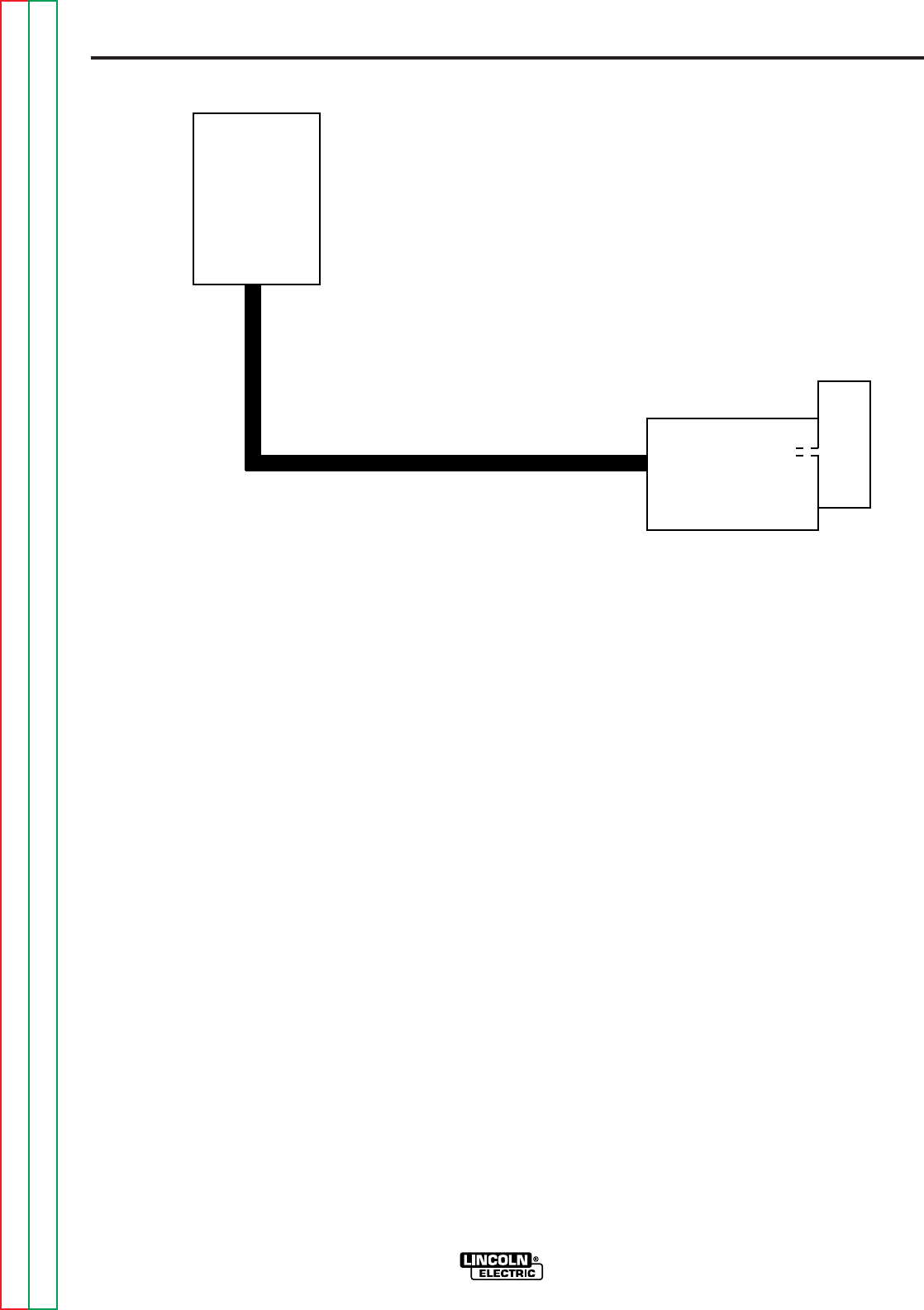
E-2
THEORY OF OPERATION
E-2
POWER WAVE 455/POWER FEED 10
specific requirements and also locate and
identify each piece of equipment for maxi-
mum efficiency and ease of operation.
SYSTEM DIAGRAM A
This basic system utilizes two physical
pieces of equipment. Refer to Figure E.1.
The power source (Power Wave 455) and
the combination Control Box and wire drive
(Power Feed 10) are the two circuit ele-
ments. Note the Control Box (user inter-
face) is attached to, and internally connect-
ed to, the wire drive unit.
The communication cable is depicted by the
heavy black connector line. PC board
power, communications and intelligence
between the power source and the combi-
nation wire drive/control box unit are con-
veyed through this cable.
MODULAR INVERTER
BASED WELDING SYSTEM
The Welding Network is an assembly of
welding equipment joined together by a
common network communication cable.
These individual welding components con-
sist of a power source (Power Wave 455), a
user interface (Power Feed 10 Control Box)
and a modular wire drive (Power Feed 10
Wire Drive). Each discrete element in the
system is designed to “talk” with the other
system components so that all information
is shared and the entire system is in sync.
This communication and shared information
network lays the groundwork for a system
with superior welding performance and
capabilities.
The equipment can be connected together
in a daisy-chain fashion. Lincoln customers
can configure a system to meet their
FIGURE E.1 — SYSTEM DIAGRAM A.
POWER
SOURCE
CONTROL BOX
(USER INTERFACE)
WIRE DRIVE
INTERNAL
CONNECTION
Return to Section TOC Return to Section TOC Return to Section TOC Return to Section TOC
Return to Master TOC Return to Master TOC Return to Master TOC Return to Master TOC
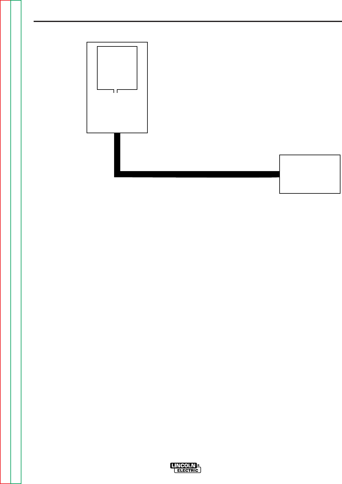
E-3
THEORY OF OPERATION
E-3
POWER WAVE 455/POWER FEED 10
The communication cable is depicted by the
heavy black connector line. PC board
power, communications and intelligence
between the wire drive and combination
power source/Control Box unit are con-
veyed through this cable.
SYSTEM DIAGRAM B
This system utilizes two physical pieces of
equipment. Refer to Figure E.2. The combi-
nation Control Box (user interface) and
power source (Power Wave 455) make up
one of the circuit elements. This combina-
tion unit is coupled to the wire drive module
(Power Feed 10). Note the Control Box is
attached to and internally connected to the
power source.
FIGURE E.2 — SYSTEM DIAGRAM B.
CONTROL
BOX
(USER
INTERFACE)
POWER
SOURCE
INTERNAL
CONNECTION
WIRE DRIVE
Return to Section TOC Return to Section TOC Return to Section TOC Return to Section TOC
Return to Master TOC Return to Master TOC Return to Master TOC Return to Master TOC
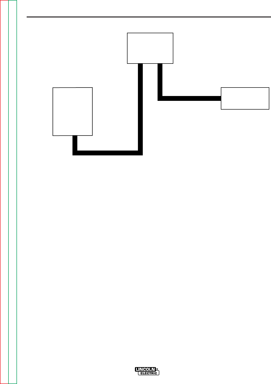
E-4
THEORY OF OPERATION
E-4
POWER WAVE 455/POWER FEED 10
cables. All PC board power, communica-
tions and intelligence are transmitted via the
two cables.
This component configuration might be
used if the wire drive unit was mounted on a
boom and the Control Box located remotely
from the power source.
SYSTEM DIAGRAM C
The power source (Power Wave 455), the
Control Box (user interface) and the wire
drive (Power Feed 10) are the three dis-
crete and physically separate circuit compo-
nents employed in this configuration. Refer
to Figure E.3. The three elements are daisy-
chained together via the communication
FIGURE E.3 — SYSTEM DIAGRAM C.
POWER
SOURCE
CONTROL BOX
(USER
INTERFACE)
WIRE DRIVE
Return to Section TOC Return to Section TOC Return to Section TOC Return to Section TOC
Return to Master TOC Return to Master TOC Return to Master TOC Return to Master TOC
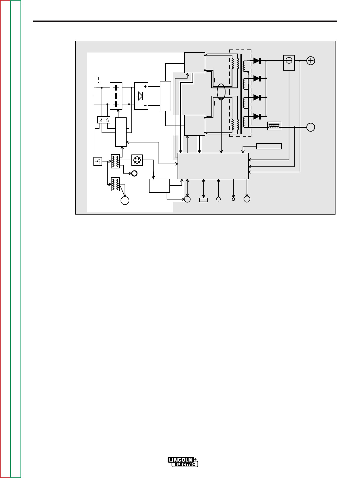
E-5
THEORY OF OPERATION
E-5
POWER WAVE 455/POWER FEED 10
voltage developed by the No. 2 auxiliary
transformer is applied to the 115 VAC
receptacle.
The 65 VDC produced from the power
board rectifier is utilized by the power board
to provide various DC voltages for the con-
trol board and wire feeder.
The two phases which are connected to the
input board, through the power switch, are
connected to the input rectifier. During
precharge or “soft start” these two phases
are current limited by the input board. This
AC input voltage is rectified, and the resul-
tant DC voltage is applied through the
reconnect switches to the input capacitors
located on the switch boards. The control
board monitors the voltage across the
capacitors. When the capacitors have
charged to an acceptable level, the control
board signals the input board to energize
the main input contactor making all three
phases of input power, without current limit-
ing, available to the input capacitors. At
this point, the Power Wave 455 is in the
“Run Mode” of operation. If the capacitors
become under or overvoltage, the control
board will signal the input board to de-
energize the main input contactor, and the
Power Wave 455 will be disabled.
POWER SOURCE
GENERAL DESCRIPTION
The Power Wave 455 is an inverter based
welding power source that is designed to be
part of a modular, multi-process welding
system. It is a high performance, digitally
controlled inverter capable of complex,
high-speed waveform control. With the
appropriate modular components it can sup-
port constant current, constant voltage and
pulse welding processes. The output rating
is 450 amps at 38 volts with a 100% duty
cycle.
INPUT VOLTAGE AND
PRECHARGE
The Power Wave 455 can be connected for
a variety of three phase voltages. Refer to
Figure E.4. The initial input power is
applied to the Power Wave 455 through a
line switch located on the front of the
machine. Two phases of the three-phase
input power is applied to the input board
and both auxiliary transformers. The vari-
ous secondary voltages developed by the
#1 auxiliary transformer are applied to the
input board, the power board rectifier and
the fan motor. The 115 VAC secondary
FIGURE E.4 — INPUT VOLTAGE AND RECHARGE.
INPUT
CONTACTOR INPUT
RECTIFIER
R
E
C
O
N
N
E
C
T
CONTROL BOARD
RIGHT
SWITCH
BOARD
LEFT
SWITCH
BOARD
MAIN
TRANSFORMER CURRENT
SENSOR
CHOKE
OUTPUT
TERMINAL
OUTPUT
TERMINAL
POWER
BOARD
115VAC
RECEPTACLE
P
O
W
E
R
S
W
I
T
C
HI
N
P
U
T
B
O
A
R
D
FAN
MOTOR
AUX.
TRANS.
AUX.
TRANS.
RECTIFIER
AUX.
RECONNECT
PRIMARY
CURRENT
SENSOR
WIRE FEEDER
RECEPTACLE RS232
CONN.
THERMOSTATS
STATUS
LIGHT
THERMAL
LIGHT
CURRENT FEEDBACK
VOLTAGE FEEDBACK
65VDC
40VDC
CONTROL SIGNALS PWM
CAPACITOR
VOLTAGE
FEEDBACK
PWM
DRIVE
VOLTAGE
SENSE
RECEPTACLE
#1
#2
S
W
I
T
C
H
DRIVE FEEDBACK
VOLTAGE
CAPACITOR
Return to Section TOC Return to Section TOC Return to Section TOC Return to Section TOC
Return to Master TOC Return to Master TOC Return to Master TOC Return to Master TOC
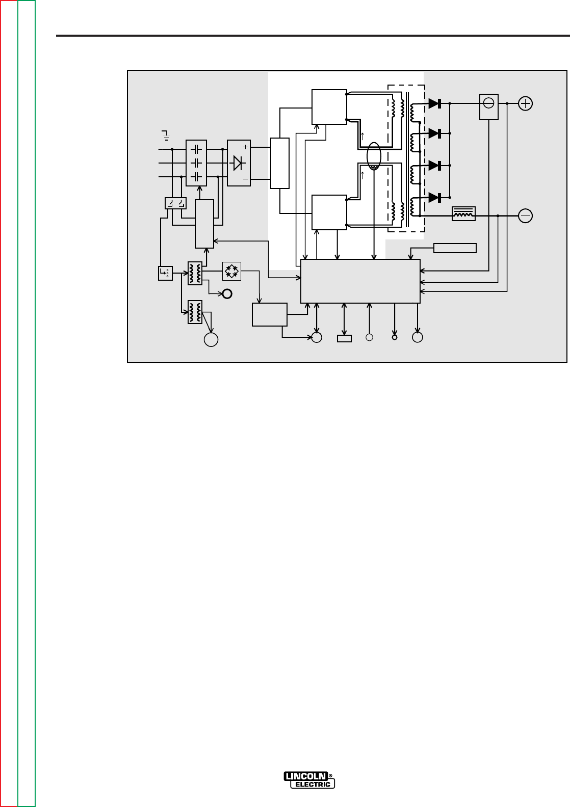
E-6
THEORY OF OPERATION
E-6
POWER WAVE 455/POWER FEED 10
Each switch board feeds current to a sepa-
rate, oppositely wound primary winding of
the main transformer. The reverse direc-
tions of current flow through the main trans-
former primaries and the offset timing of the
IGBT switch boards induce an AC square
wave output signal at the secondary of the
main transformer. These primary currents
are monitored by the current transformer
(CT). If the primary currents become abnor-
mally high, the control board will shut off the
IGBTs, thus disabling machine output. The
DC current flow through each primary wind-
ing is clamped back to each respective
input capacitor when the IGBTs are turned
off. This is needed due to the inductance of
the transformer primary winding. The firing
of the two switch boards occurs during
halves of a 50 microsecond interval, creat-
ing a constant 20 kHz output.
SWITCH BOARDS AND
MAIN TRANSFORMER
There are two switch boards in the Power
Wave 455, each containing an input capaci-
tor and insulated gate bipolar transistor
(IGBT) switching circuitry. Refer to Figure
E.5. When the machine reconnect switches
are configured for a lower input voltage
(below 300 VAC) the input capacitors are
connected in parallel. When the machine is
configured for higher input voltages (300
VAC and above) the input capacitors are
connected in series.
When the input capacitors are fully charged
they act as power supplies for the IGBT
switching circuit. The Insulated Gate
Bipolar Transistors switch the DC power,
from the input capacitors, “on and off” thus
supplying pulsed DC current to the main
transformer primary windings. See
IGBT
Operation Discussion and Diagrams
in
this section.
FIGURE E.5 — SWITCH BOARDS AND MAIN TRANSFORMER.
INPUT
CONTACTOR INPUT
RECTIFIER
R
E
C
O
N
N
E
C
T
CONTROL BOARD
RIGHT
SWITCH
BOARD
LEFT
SWITCH
BOARD
MAIN
TRANSFORMER CURRENT
SENSOR
CHOKE
OUTPUT
TERMINAL
OUTPUT
TERMINAL
POWER
BOARD
115VAC
RECEPTACLE
P
O
W
E
R
S
W
I
T
C
HI
N
P
U
T
B
O
A
R
D
FAN
MOTOR
AUX.
TRANS.
AUX.
TRANS.
RECTIFIER
AUX.
RECONNECT
PRIMARY
CURRENT
SENSOR
WIRE FEEDER
RECEPTACLE RS232
CONN.
THERMOSTATS
STATUS
LIGHT
THERMAL
LIGHT
CURRENT FEEDBACK
VOLTAGE FEEDBACK
65VDC
40VDC
CONTROL SIGNALS PWM
DRIVE
CAPACITOR
VOLTAGE
FEEDBACK
CAPACITOR
VOLTAGE
FEEDBACK
PWM
DRIVE
VOLTAGE
SENSE
RECEPTACLE
#1
#2
S
W
I
T
C
H
Return to Section TOC Return to Section TOC Return to Section TOC Return to Section TOC
Return to Master TOC Return to Master TOC Return to Master TOC Return to Master TOC
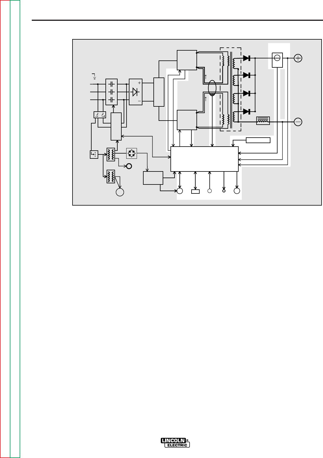
E-7
THEORY OF OPERATION
E-7
POWER WAVE 455/POWER FEED 10
pulse width modulation (PWM) signal (See
Pulse Width Modulation
in this section) is
sent to the switch board IGBTs. In this
manner, the digitally controlled high-speed
welding waveform is created.
The control board also monitors the ther-
mostats, main transformer primary current,
and capacitor voltage, and activates either
the thermal light and/or the status light.
Dependent upon the fault situation, the con-
trol board will either disable or reduce
machine output, or de-energize the main
input contactor.
CONTROL BOARD
The control board performs the primary
interfacing functions to establish and main-
tain output control of the Power Wave 455.
Refer to Figure E.6. The control board
sends and receives digital command infor-
mation through the wire feeder receptacle
and or the RS232 connector. The software
that is contained within the control board
processes and compares these commands
with the voltage and current feedback infor-
mation it receives from the current sensor
and voltage sensing leads. The appropriate
FIGURE E.6 — CONTROL BOARD.
INPUT
CONTACTOR INPUT
RECTIFIER
R
E
C
O
N
N
E
C
T
CONTROL BOARD
RIGHT
SWITCH
BOARD
LEFT
SWITCH
BOARD
MAIN
TRANSFORMER CURRENT
SENSOR
CHOKE
OUTPUT
TERMINAL
OUTPUT
TERMINAL
POWER
BOARD
115VAC
RECEPTACLE
P
O
W
E
R
S
W
I
T
C
HI
N
P
U
T
B
O
A
R
D
FAN
MOTOR
AUX.
TRANS.
AUX.
TRANS.
RECTIFIER
AUX.
RECONNECT
PRIMARY
CURRENT
SENSOR
WIRE FEEDER
RECEPTACLE RS232
CONN.
THERMOSTATS
STATUS
LIGHT
THERMAL
LIGHT
CURRENT FEEDBACK
VOLTAGE FEEDBACK
65VDC
40VDC
CONTROL SIGNALS PWM
DRIVE
CAPACITOR
VOLTAGE
FEEDBACK
CAPACITOR
VOLTAGE
FEEDBACK
PWM
DRIVE
VOLTAGE
SENSE
RECEPTACLE
#1
#2
S
W
I
T
C
H
Return to Section TOC Return to Section TOC Return to Section TOC Return to Section TOC
Return to Master TOC Return to Master TOC Return to Master TOC Return to Master TOC
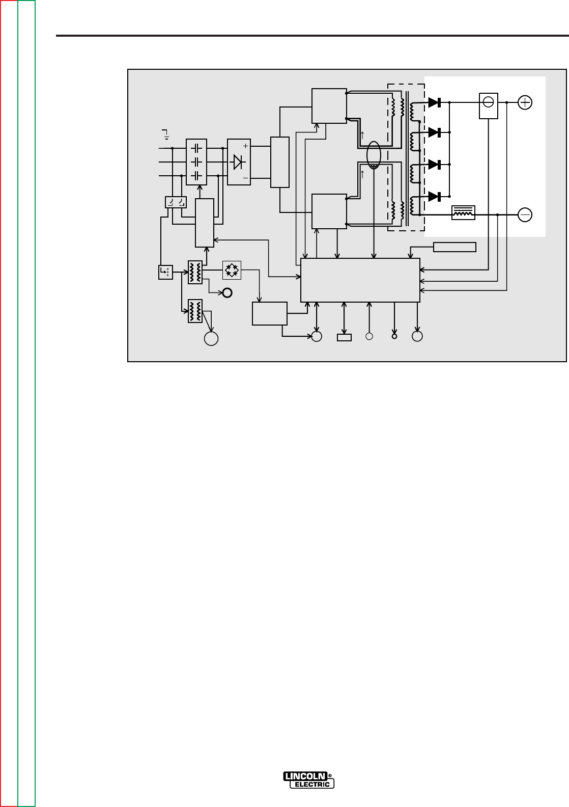
E-8
THEORY OF OPERATION
E-8
POWER WAVE 455/POWER FEED 10
rectifies it to a DC voltage level. Since the
output choke is in series with the negative
leg of the output rectifier and also in series
with the welding load, a filtered DC output is
applied to the machine output terminals.
Refer to Figure E.7.
OUTPUT RECTIFIER
AND CHOKE
The output rectifier receives the AC output
from the main transformer secondary and
FIGURE E.7 — OUTPUT RECTIFIER AND CHOKE.
INPUT
CONTACTOR INPUT
RECTIFIER
R
E
C
O
N
N
E
C
T
CONTROL BOARD
RIGHT
SWITCH
BOARD
LEFT
SWITCH
BOARD
MAIN
TRANSFORMER CURRENT
SENSOR
CHOKE
OUTPUT
TERMINAL
OUTPUT
TERMINAL
POWER
BOARD
115VAC
RECEPTACLE
P
O
W
E
R
S
W
I
T
C
HI
N
P
U
T
B
O
A
R
D
FAN
MOTOR
AUX.
TRANS.
AUX.
TRANS.
RECTIFIER
AUX.
RECONNECT
PRIMARY
CURRENT
SENSOR
WIRE FEEDER
RECEPTACLE RS232
CONN.
THERMOSTATS
STATUS
LIGHT
THERMAL
LIGHT
CURRENT FEEDBACK
VOLTAGE FEEDBACK
65VDC
40VDC
CONTROL SIGNALS PWM
DRIVE
CAPACITOR
VOLTAGE
FEEDBACK
CAPACITOR
VOLTAGE
FEEDBACK
PWM
DRIVE
VOLTAGE
SENSE
RECEPTACLE
#1
#2
S
W
I
T
C
H
Return to Section TOC Return to Section TOC Return to Section TOC Return to Section TOC
Return to Master TOC Return to Master TOC Return to Master TOC Return to Master TOC

E-9
THEORY OF OPERATION
E-9
POWER WAVE 455/POWER FEED 10
OVER CURRENT
PROTECTION
If the average current exceeds 590 amps,
then the peak current will be limited to 100
amps until the average current decreases to
under 50 amps.
UNDER/OVER VOLTAGE
PROTECTION
A protective circuit is included on the
control board to monitor the voltage across
the input capacitors. In the event that a
capacitor voltage is too high, or too low, the
protection circuit will de-energize the input
contactor. Machine output will be disabled
and the “soft start” mode will be repeated.
The protection circuit will prevent output if
any of the following circumstances occur.
1. Capacitor conditioning is required.
(May be required if machine has been
off for a long period of time and is con-
nected for high input voltage operation.)
2. Voltage across a capacitor exceeds
390 volts. (High line surges or improp-
er input voltage connections.)
3. Voltage across a capacitor is under 70
volts. (Due to improper input voltage
connections.)
4. Internal component damage.
THERMAL PROTECTION
Two normally closed (NC) thermostats pro-
tect the machine from excessive operating
temperatures. These thermostats are wired
in series and are connected to the control
board. One of the thermostats is located on
the heat sink of the output rectifier and the
other is located near the fan. (On later pro-
duction machines this thermostat is located
on the output choke) Excessive tempera-
tures may be caused by a lack of cooling air
or operating the machine beyond its duty
cycle or output rating. If excessive operat-
ing temperatures should occur, the ther-
mostats will prevent output from the
machine. The yellow thermal light, located
on the front of the machine, will be illuminat-
ed. The thermostats are self-resetting once
the machine cools sufficiently. If the ther-
mostat shutdown was caused by excessive
output or duty cycle and the fan is operating
normally, the power switch may be left on
and the reset should occur within a 15-
minute period. If the fan is not turning or
the air intake louvers are obstructed, then
the power must be removed from the
machine, and the fan problem or air
obstruction corrected. On later production
machines (above code 10500) the cooling
fan runs only when necessary. The F.A.N.
(fan as needed) system is controlled by the
control board via a solid state relay.
PROTECTIVE CIRCUITS
Protective circuits are designed into the
Power Wave 455 to sense trouble and shut
down the machine before damage occurs to
the machine's internal components.
Return to Section TOC Return to Section TOC Return to Section TOC Return to Section TOC
Return to Master TOC Return to Master TOC Return to Master TOC Return to Master TOC
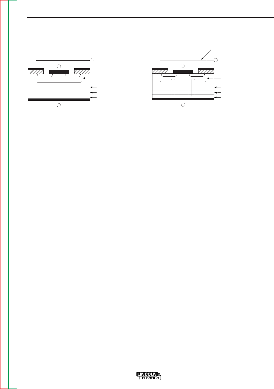
E-10
THEORY OF OPERATION
E-10
POWER WAVE 455/POWER FEED 10
connected to the source. The circuit is
turned OFF like a light switch.
Example B shows the IGBT in an active
mode. When the gate signal , a positive DC
voltage relative to the source, is applied to
the gate terminal of the IGBT, it is capable
of conducting current. A voltage supply con-
nected to the drain terminal will allow the
IGBT to conduct and supply current to the
circuit components coupled to the source.
Current will flow through the conducting
IGBT to downstream components as long
as the positive gate signal is present. This is
similar to turning ON a light switch.
INSULATED GATE BIPOLAR
TRANSISTOR (IGBT)
OPERATION
An IGBT is a type of transistor. IGBT are
semiconductors well suited for high frequen-
cy switching and high current applications.
Example A in Figure E.8 shows an IGBT in
passive mode. There is no gate signal, zero
volts relative to the source, and therefore,
no current flow. The drain terminal of the
IGBT may be connected to a voltage sup-
ply; but since there is no conduction, the cir-
cuit will not supply current to components
FIGURE E.8 — IGBT OPERATION.
DRAIN
SOURCE GATE
A. PASSIVE B. ACTIVE
BODY REGION
DRAIN DRIFT REGION
BUFFER LAYER
INJECTING LAYER
DRAIN
SOURCE GATE
BODY REGION
DRAIN DRIFT REGION
BUFFER LAYER
INJECTING LAYER
n+ n+
P
n-
n+
P+
n+ n+
P
n-
n+
P+
POSITIVE
VOLTAGE
APPLIED
Return to Section TOC Return to Section TOC Return to Section TOC Return to Section TOC
Return to Master TOC Return to Master TOC Return to Master TOC Return to Master TOC
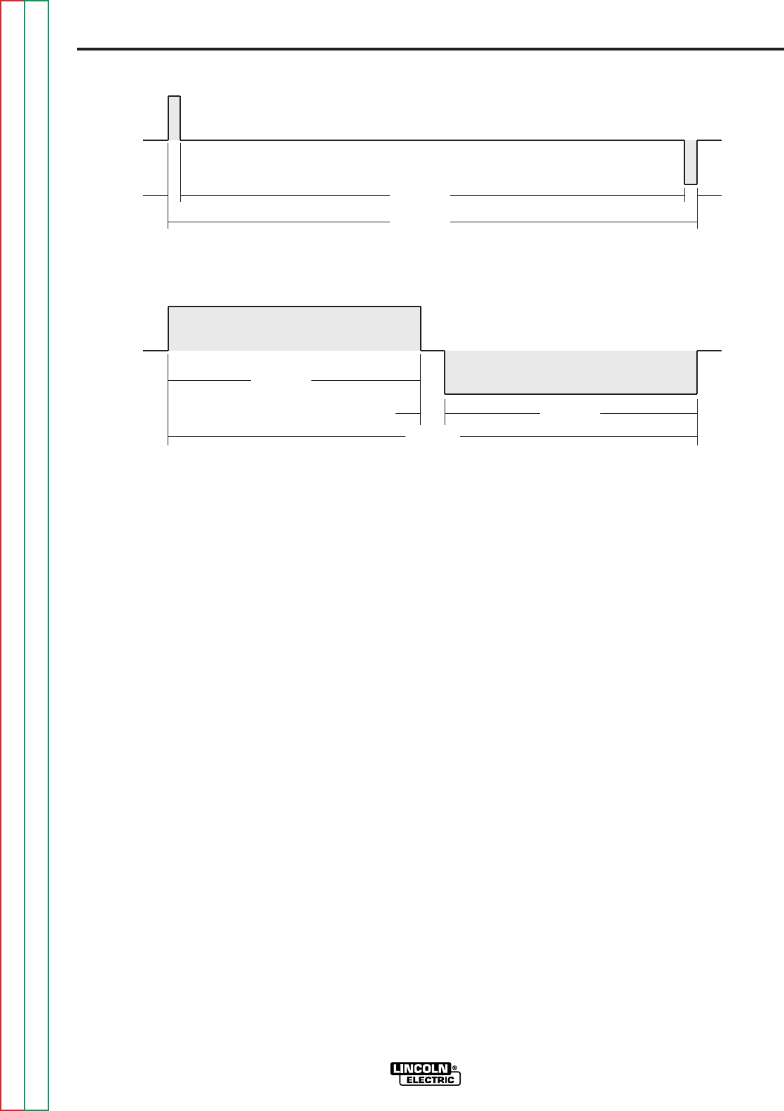
E-11
THEORY OF OPERATION
E-11
POWER WAVE 455/POWER FEED 10
microsecond. The negative portion is the
other IGBT group1. The dwell time (off time)
is 48 microseconds (both IGBT groups off).
Since only two microseconds of the 50-
microsecond time period is devoted to con-
ducting, the output power is minimized.
MAXIMUM OUTPUT
By holding the gate signal on for 24
microseconds each, and allowing only two
microseconds of dwell time (off time) during
the 50-microsecond cycle, the output is
maximized. The darkened area under the
top curve can be compared to the area
under the bottom curve. The more dark
area that is under the curve indicates that
more power is present.
1An IGBT group consists of two IGBT
modules feeding one transformer primary
winding.
PULSE WIDTH
MODULATION
The term Pulse Width Modulation is used to
describe how much time is devoted to con-
duction in the positive and negative portions
of the cycle. Changing the pulse width is
known as modulation. Pulse Width
Modulation (PWM) is the varying of the
pulse width over the allowed range of a
cycle to affect the output of the machine.
MINIMUM OUTPUT
By controlling the duration of the gate sig-
nal, the IGBT is turned on and off for differ-
ent durations during the cycle. The top
drawing in Figure E.9 shows the minimum
output signal possible over a 50-microsec-
ond time period.
The positive portion of the signal represents
one IGBT group1conducting for one
FIGURE E.9 — TYPICAL IGBT OUTPUTS.
(+)
1 µsec 48 µsec
50 µsec
1 µsec
(-)
(+)
(-)
2 µsec
24 µsec
50 µsec
24 µsec
MINIMUM OUTPUT
MAXIMUM OUTPUT
Return to Section TOC Return to Section TOC Return to Section TOC Return to Section TOC
Return to Master TOC Return to Master TOC Return to Master TOC Return to Master TOC
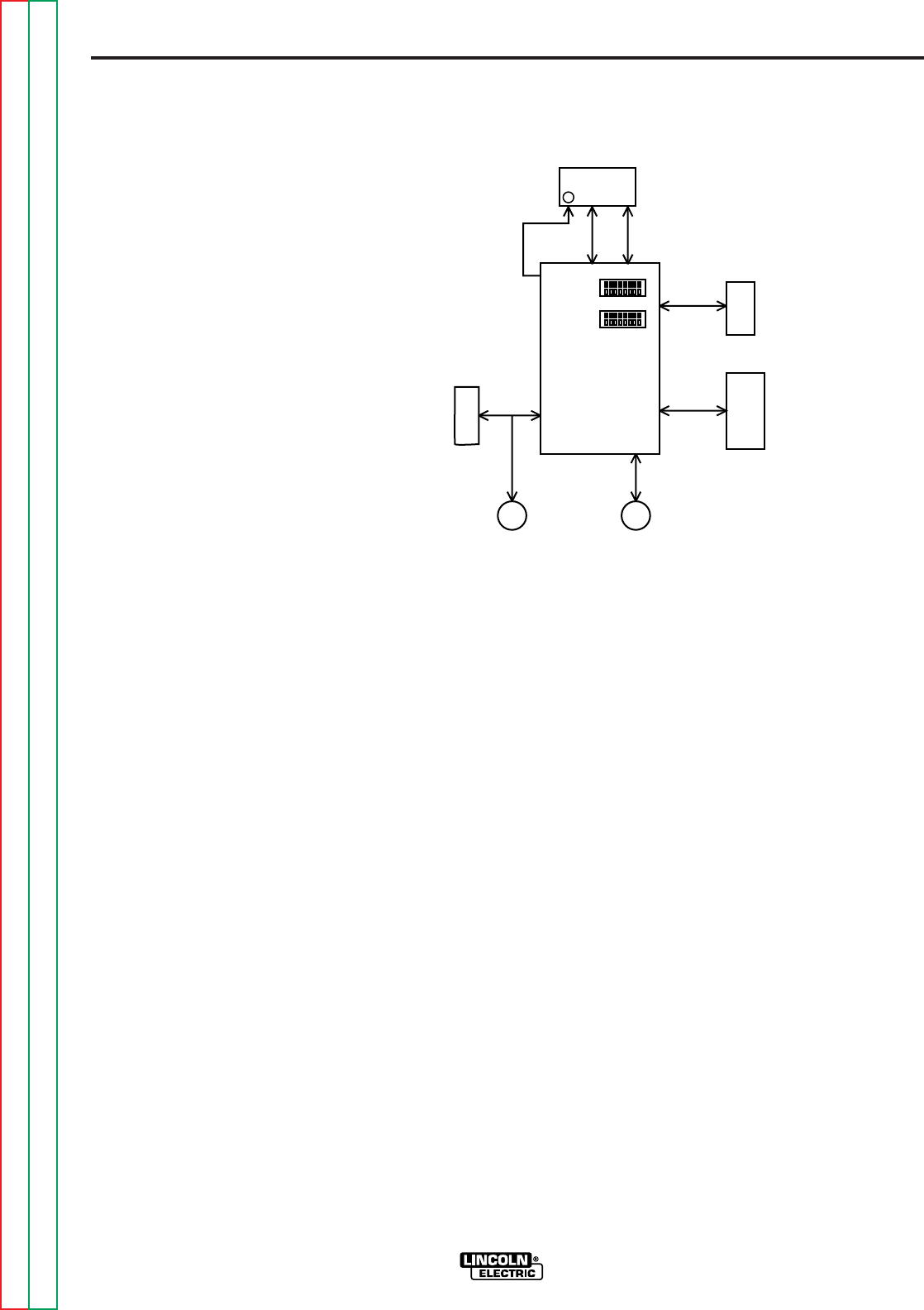
E-12
THEORY OF OPERATION
E-12
POWER WAVE 455/POWER FEED 10
In addition to the large and smaller size
options, there is a Display Panel which is
standard on the Control Box unit. The
Display Panel, typically installed in the
upper position of the Control Box assembly,
houses the encoder controls and the STA-
TUS LED. The controls are used to adjust
the wire feed speed, current, voltage and
trim parameters. The STATUS LED is
designed to blink a red and green code if a
fault should occur.
The internal Network Connector is used
when the Control Box is mounted on either
the power source or the wire drive units.
See
System Diagram A
and
System
Diagram B
in this section.
The optional Network Input and Output
receptacles are utilized when the Control
Box assembly is mounted independently
from both the wire drive and power source.
See
System Diagram C
in this section.
There are two DIP switch banks located on
the motherboard. They are labeled S1 and
S2 and are used to set display, trigger,
acceleration and run in functions.
CONTROL BOX
(USER INTERFACE)
The system Control Box is the main entry
point for all system parameters, and from it
the user can control both power source and
wire feeder functions. Refer to Figure E.10.
The user interface motherboard is the heart
of the Control Box. Dependent upon the
option panels and the information received
through the network cable, it directs the
entire system as to the options, wire feed
speed, and weld cycle requirements and
parameters.
The options are divided into two physical
size categories. The smaller option, typical-
ly installed in the middle section of the con-
trol box, is dedicated to dual procedure,
head selection, and memory related func-
tions. The larger, or bottom section, is
reserved for control of the setup functions
for the power source (Power Wave 455)
and wire drive (Power Feeder 10) such as
mode, arc control, run in and timer set up.
FIGURE E.10 — CONTROL BOX (USER INTERFACE).
SMALL
PANEL
OPTIONS
LARGE
PANEL
OPTIONS
AMPHENOL-OUTPUT
NETWORK RECEPTACLE
(OPTIONAL)
AMPHENOL-INPUT
NETWORK RECEPTACLE
(OPTIONAL)
NETWORK
CONNECTOR
(INTERNAL)
DIP
SWITCHES
STATUS
LED
DISPLAY AND
ENCODER PANEL
(STANDARD)
USER
INTERFACE
MOTHER-
BOARD
Return to Section TOC Return to Section TOC Return to Section TOC Return to Section TOC
Return to Master TOC Return to Master TOC Return to Master TOC Return to Master TOC

E-13
THEORY OF OPERATION
E-13
POWER WAVE 455/POWER FEED 10
the correct commands are transmitted to
the feed drive. The feed drive control board
then sends the signals to energize the
active components such as the solenoid
and wire drive motor. The tach feedback
signal is processed on the control board
which regulates the motor armature voltage
so as to maintain the required wire feed
speed.
When the gun trigger is pulled, the voltage
sense board relays the electrode sense sig-
nal to the input network receptacle for pro-
cessing by the Control Box.
The optional shutdown feature can be
implemented as a means of stopping the
wire feeding in the event that the water
cooler (if used) is not turned on.
The STATUS LED is designed to blink a red
and green code if a fault should occur.
There is one DIP switch bank located on the
wire drive control board. It is labeled S1
and is used to set gear ratios, arc polarity,
and for network identification purposes.
POWER FEED 10
FEED HEAD
The Power Feed 10 is a four roll, high per-
formance, digitally controlled, modular wire
feeder that operates on 40 VDC input
power. It is designed to be part of a modu-
lar, multi-process welding system. Refer to
Figure E.11.
Network communications, intelligence, PC
board input power, and arc voltage feed-
back is received and transmitted through
the input network receptacle. The internal
network connector plug is utilized when the
Control Box is mounted directly to the wire
drive unit. See
System Diagram A
in this
section. The optional network output recep-
tacle is used when the system components
are connected in a daisy-chain fashion.
The feed drive control board processes the
information it receives from the various user
operated switches such as the gun trigger,
2-step/4-step, and cold inch switches and
sends this information to other system com-
ponents. This information is evaluated and
FIGURE E.11 — POWER FEED 10 FEED HEAD.
CONTROL BOARD
LEAD #67A
VOLTAGE
SENSE
LEAD #67
DRIVE
MOTOR GEAR BOX
AND
CONDUCTOR
BLOCK
TACH
FEEDBACK
STATUS LED
2-STEP/
4-STEP
GUN TRIGGER AND
DUAL PROCEDURE
RECEPTACLE
TO POWER
SOURCE OR
CONTROL
BOX
DIP SWITCH
INPUT
NETWORK
RECEPTACLE
NETWORK
CONNECTOR
(INTERNAL) COLD
INCH/
GAS
PURGE
GAS
SOLENOID
NETWORK
OUTPUT
RECEPTACLE
(OPTIONAL)
SHUTDOWN
Return to Section TOC Return to Section TOC Return to Section TOC Return to Section TOC
Return to Master TOC Return to Master TOC Return to Master TOC Return to Master TOC


TROUBLESHOOTING AND REPAIR
POWER WAVE 455/POWER FEED 10
SECTION F-1SECTION F-1
TABLE OF CONTENTS
-TROUBLESHOOTING AND REPAIR SECTION-
Troubleshooting and Repair . . . . . . . . . . . . . . . . . . . . . . . . . . . . . . . . . . . . . . . . . . . . . . . . . . . . . . . . . . Section F
How to Use Troubleshooting Guide . . . . . . . . . . . . . . . . . . . . . . . . . . . . . . . . . . . . . . . . . . . . . . . . . F-2
PC Board Troubleshooting Procedures . . . . . . . . . . . . . . . . . . . . . . . . . . . . . . . . . . . . . . . . . . . . . . F-3
Troubleshooting Guide . . . . . . . . . . . . . . . . . . . . . . . . . . . . . . . . . . . . . . . . . . . . . . . . . . . . . . . . . . . F-5
Power Wave . . . . . . . . . . . . . . . . . . . . . . . . . . . . . . . . . . . . . . . . . . . . . . . . . . . . . . . . . . . . . . . . F-5
Power Feed . . . . . . . . . . . . . . . . . . . . . . . . . . . . . . . . . . . . . . . . . . . . . . . . . . . . . . . . . . . . . . . . F-13
Power Wave 455 Control Board LED Definitions . . . . . . . . . . . . . . . . . . . . . . . . . . . . . . . . . . . . . . . F-22
Test Procedures . . . . . . . . . . . . . . . . . . . . . . . . . . . . . . . . . . . . . . . . . . . . . . . . . . . . . . . . . . . . . . . . F-23
Input Filter Capacitor Discharge Procedure . . . . . . . . . . . . . . . . . . . . . . . . . . . . . . . . . . . . . . . . F-23
Switch Board Test . . . . . . . . . . . . . . . . . . . . . . . . . . . . . . . . . . . . . . . . . . . . . . . . . . . . . . . . . . . F-25
Output Rectifier Test . . . . . . . . . . . . . . . . . . . . . . . . . . . . . . . . . . . . . . . . . . . . . . . . . . . . . . . . . . F-29
Input Rectifier Test . . . . . . . . . . . . . . . . . . . . . . . . . . . . . . . . . . . . . . . . . . . . . . . . . . . . . . . . . . . F-31
Input Contactor Test . . . . . . . . . . . . . . . . . . . . . . . . . . . . . . . . . . . . . . . . . . . . . . . . . . . . . . . . . . F-35
Auxiliary Transformer No. 2 Test . . . . . . . . . . . . . . . . . . . . . . . . . . . . . . . . . . . . . . . . . . . . . . . . F-37
Auxiliary Transformer No. 1 Test . . . . . . . . . . . . . . . . . . . . . . . . . . . . . . . . . . . . . . . . . . . . . . . . F-39
Power Board Test . . . . . . . . . . . . . . . . . . . . . . . . . . . . . . . . . . . . . . . . . . . . . . . . . . . . . . . . . . . . F-43
Current Transducer Test . . . . . . . . . . . . . . . . . . . . . . . . . . . . . . . . . . . . . . . . . . . . . . . . . . . . . . F-47
Drive Motor Test . . . . . . . . . . . . . . . . . . . . . . . . . . . . . . . . . . . . . . . . . . . . . . . . . . . . . . . . . . . . . F-51
Tach Feedback Test . . . . . . . . . . . . . . . . . . . . . . . . . . . . . . . . . . . . . . . . . . . . . . . . . . . . . . . . . . F-53
Voltage Sense PC Board Test . . . . . . . . . . . . . . . . . . . . . . . . . . . . . . . . . . . . . . . . . . . . . . . . . . F-55
Dual Encoder PC Board Test . . . . . . . . . . . . . . . . . . . . . . . . . . . . . . . . . . . . . . . . . . . . . . . . . . . F-57
Control Cable Continuity Test . . . . . . . . . . . . . . . . . . . . . . . . . . . . . . . . . . . . . . . . . . . . . . . . . . . F-59
Component Replacement Procedures . . . . . . . . . . . . . . . . . . . . . . . . . . . . . . . . . . . . . . . . . . . . . . . F-61
Gas Solenoid Removal and Replacement . . . . . . . . . . . . . . . . . . . . . . . . . . . . . . . . . . . . . . . . . F-61
Wire Feeder Control Board Removal And Replacement . . . . . . . . . . . . . . . . . . . . . . . . . . . . . . F-63
Tach (Hall Effect) Assembly Removal and Replacement . . . . . . . . . . . . . . . . . . . . . . . . . . . . . . F-65
Gear Box and Drive Motor Removal and Replacement . . . . . . . . . . . . . . . . . . . . . . . . . . . . . . . F-67
Switch Board and Filter Capacitor Removal and Replacement . . . . . . . . . . . . . . . . . . . . . . . . . F-71
Meter Accuracy Check . . . . . . . . . . . . . . . . . . . . . . . . . . . . . . . . . . . . . . . . . . . . . . . . . . . . . . . . F-74
Control or Power Board Removal and Replacement . . . . . . . . . . . . . . . . . . . . . . . . . . . . . . . . . F-75
Auxiliary Transformer No. 1 Removal and Replacement Procedure . . . . . . . . . . . . . . . . . . . . . F-79
Main Input Contactor Removal and Replacement . . . . . . . . . . . . . . . . . . . . . . . . . . . . . . . . . . . F-83
Input Rectifier Removal and Replacement . . . . . . . . . . . . . . . . . . . . . . . . . . . . . . . . . . . . . . . . . F-87
Output Rectifier and Module Removal and Replacement . . . . . . . . . . . . . . . . . . . . . . . . . . . . . F-89
Troubleshooting Flowcharts . . . . . . . . . . . . . . . . . . . . . . . . . . . . . . . . . . . . . . . . . . . . . . . . . . . . . . . F-93
Power Source Error Interpretation Guide . . . . . . . . . . . . . . . . . . . . . . . . . . . . . . . . . . . . . . . . . . F-93
Performance Troubleshooting Guide . . . . . . . . . . . . . . . . . . . . . . . . . . . . . . . . . . . . . . . . . . . . . F-94
Functional Troubleshooting Guide . . . . . . . . . . . . . . . . . . . . . . . . . . . . . . . . . . . . . . . . . . . . . . . F-95
Return to Master TOC Return to Master TOC Return to Master TOC Return to Master TOC

POWER WAVE 455/POWER FEED 10
F-2
TROUBLESHOOTING AND REPAIR
F-2
This Troubleshooting Guide is provided to
help you locate and repair possible machine
malfunctions. Simply follow the three-step
procedure listed below.
Step 1. LOCATE PROBLEM (SYMPTOM).
Look under the column labeled “PROBLEM
(SYMPTOMS)”. This column describes
possible symptoms that the machine may
exhibit. Find the listing that best describes
the symptom that the machine is exhibiting.
Symptoms are grouped into the following
categories: function problems, feeding prob-
lems, and welding problems.
Step 2. PERFORM EXTERNAL TESTS.
The second column labeled “POSSIBLE
AREAS OF MISADJUSTMENT(S)” lists the
obvious external possibilities that may con-
tribute to the machine symptom. Perform
these tests/checks in the order listed. In
general, these tests can be conducted with-
out removing the case wrap-around cover.
Step 3. RECOMMENDED COURSE OF
ACTION.
The last column labeled “RECOMMENDED
COURSE OF ACTION” lists the most likely
components that may have failed in your
machine. It also specifies the appropriate
test procedure to verify that the subject
component is either good or bad. If there
are a number of possible components,
check the components in the order listed to
eliminate one possibility at a time until you
locate the cause of your problem.
All of the referenced test procedures
referred to in the Troubleshooting Guide are
described in detail at the end of this chap-
ter. Refer to the Troubleshooting and Repair
Table of Contents to locate each specific
Test Procedure. All of the specified test
points, components, terminal strips, etc. can
be found on the referenced electrical wiring
diagrams and schematics. Refer to the
Electrical Diagrams Section Table of
Contents to locate the appropriate diagram.
HOW TO USE TROUBLESHOOTING GUIDE
Service and Repair should only be performed by Lincoln Electric Factory Trained
Personnel. Unauthorized repairs performed on this equipment may result in danger to
the technician and machine operator and will invalidate your factory warranty. For your
safety and to avoid electrical shock, please observe all safety notes and precautions
detailed throughout this manual.
---------------------------------------------------------------------------------------------------------
WARNING
CAUTION
If for any reason you do not understand the test procedures or are unable to perform the
tests/repairs safely, contact the Lincoln Electric Service Department for technical
troubleshooting assistance before you proceed. Call 216-383-2531 or 1-800-833-9353.
---------------------------------------------------------------------------------------------------------
Return to Section TOC Return to Section TOC Return to Section TOC Return to Section TOC
Return to Master TOC Return to Master TOC Return to Master TOC Return to Master TOC

F-3
TROUBLESHOOTING AND REPAIR
F-3
ELECTRIC SHOCK
can kill.
Have an electrician install
and service this equipment.
Turn the input power OFF
at the fuse box before
working on equipment. Do
not touch electrically hot
parts.
-------------------------------------------------
Sometimes machine failures appear to be
due to PC board failures. These problems
can sometimes be traced to poor electrical
connections. To avoid problems when trou-
bleshooting and replacing PC boards,
please use the following procedure:
-------------------------------------------------
1. Determine to the best of your technical
ability that the PC board is the most
likely component causing the failure
symptom.
2. Check for loose connections at the PC
board to assure that the PC board is
properly connected.
3. If the problem persists, replace the sus-
pect PC board using standard practices
to avoid static electrical damage and
electrical shock. Read the warning
inside the static resistant bag and per-
form the following procedures:
PC board can be
damaged by static
electricity.
- Remove your body’s
static charge before
opening the static-
shielding bag. Wear an
anti-static wrist strap.
For safety, use a 1 Meg
ohm resistive cord con-
nected to a grounded
part of the equipment
frame.
- If you don’t have a
wrist strap, touch an unpainted, grounded,
part of the equipment frame. Keep touching
the frame to prevent static build-up. Be sure
not to touch any electrically live parts at the
same time.
- Tools which come in contact with the PC
board must be either conductive, anti-static
or static-dissipative.
- Remove the PC board from the static-
shielding bag and place it directly into the
equipment. Don’t set the PC board on or
near paper, plastic or cloth which could
have a static charge. If the PC board cannot
be installed immediately, put it back in the
static-shielding bag.
- If the PC board uses protective shorting
jumpers, don’t remove them until installation
is complete.
- If you return a PC board to the Lincoln
Electric Company for credit, it must be in
the static-shielding bag. This will prevent
further damage and allow proper failure
analysis.
POWER WAVE 455/POWER FEED 10
PC BOARD TROUBLESHOOTING PROCEDURES
WARNING
CAUTION
ATTENTION
Static-Sensitive
Devices
Handle only at
Static-Safe
Workstations
Reusable
Container
Do Not Destroy
Return to Section TOC Return to Section TOC Return to Section TOC Return to Section TOC
Return to Master TOC Return to Master TOC Return to Master TOC Return to Master TOC

F-4
TROUBLESHOOTING AND REPAIR
F-4
4. Test the machine to determine if the
failure symptom has been corrected by
the replacement PC board.
NOTE: It is desirable to have a spare
(known good) PC board available for PC
board troubleshooting.
NOTE: Allow the machine to heat up so
that all electrical components can reach
their operating temperature.
5. Remove the replacement PC board and
substitute it with the original PC board
to recreate the original problem.
NOTE: Do not substitute boards that show
physical damage.
a. If the original problem does not reap-
pear by substituting the original
board, then the PC board was not
the problem. Continue to look for
bad connections in the control wiring
harness, junction blocks, and termi-
nal strips.
b. If the original problem is recreated
by the substitution of the original
board, then the PC board was the
problem. Reinstall the replacement
PC board and test the machine.
6. Always indicate that this procedure was
followed when warranty reports are to
be submitted.
NOTE: Following this procedure and writing
on the warranty report, “INSTALLED AND
SWITCHED PC BOARDS TO VERIFY
PROBLEM,” will help avoid denial of legiti-
mate PC board warranty claims.
POWER WAVE 455/POWER FEED 10
Return to Section TOC Return to Section TOC Return to Section TOC Return to Section TOC
Return to Master TOC Return to Master TOC Return to Master TOC Return to Master TOC

F-5
TROUBLESHOOTING AND REPAIR
F-5
POWER WAVE 455/POWER FEED 10
TROUBLESHOOTING GUIDE
POWER WAVE
Observe all Safety Guidelines detailed throughout this manual.
CAUTION
PROBLEMS
(SYMPTOMS) POSSIBLE AREAS OF
MISADJUSTMENT(S) RECOMMENDED
COURSE OF ACTION
Major physical or electrical dam-
age is evident when the sheet
metal cover(s) are removed.
The machine is dead -- no output --
no fan -- no LEDs.
The main input fuses (or breaker)
repeatedly fail.
1. Contact your local authorized
Lincoln Electric Field Service
Facility for technical assistance.
1. Make certain the input power
switch SW1 is in the ON posi-
tion.
2. Check the main input fuses. If
open, replace.
3. Check the 6 amp circuit breaker
(CB4). Reset if tripped.
4. Make certain the reconnect
panel is configured correctly for
the applied input voltage.
1. Make certain the fuses or break-
ers are properly sized.
2. Make certain the reconnect
panel is configured properly for
the applied input voltage.
3. The welding procedure may be
drawing too much input current
or the duty cycle may be too
high. Reduce the welding cur-
rent and/or reduce the duty
cycle.
If for any reason you do not understand the test procedures or are unable to perform the tests/repairs safely, contact the Lincoln Electric
Service Department for technical troubleshooting assistance before you proceed. Call 216-383-2531 or 1-800-833-9353.
-----------------------------------------------------------------------------------------------------------------------------
1. Contact the Lincoln Electric
Service Department, 216-383-
2531 or 1-800-833-9353
(WELD).
1. Check the input power switch
(SW1) for proper operation.
Also check the associated leads
for loose or faulty connections.
See wiring diagram.
2. Check CB4 for proper operation.
3. Perform the
T1 Auxiliary
Transformer Test.
4. Perform the
Power Board Test.
1. Check the reconnect switches
and associated wiring. See
wiring diagram.
2. Perform the
Input Rectifier
Test.
3. Perform the
Switch Board
Test.
OUTPUT PROBLEMS
Return to Section TOC Return to Section TOC Return to Section TOC Return to Section TOC
Return to Master TOC Return to Master TOC Return to Master TOC Return to Master TOC

F-6
TROUBLESHOOTING AND REPAIR
F-6
POWER WAVE 455/POWER FEED 10
POWER WAVE
Observe all Safety Guidelines detailed throughout this manual.
If for any reason you do not understand the test procedures or are unable to perform the tests/repairs safely, contact the Lincoln Electric
Service Department for technical troubleshooting assistance before you proceed. Call 216-383-2531 or 1-800-833-9353.
-----------------------------------------------------------------------------------------------------------------------------
CAUTION
PROBLEMS
(SYMPTOMS) POSSIBLE AREAS OF
MISADJUSTMENT(S) RECOMMENDED
COURSE OF ACTION
The Power Wave has no output --
the fan is running -- a “clicking”
sound may be heard coming from
the machine. The main contactor
CR1 is not “pulling in”. If the
STATUS LED is not steady green,
see
LED Code Table.
The fan runs slow or intermittently
-- low or no weld output.
1. Turn the input power OFF
immediately.
2. Make certain the reconnect
panel is configured correctly for
the applied input voltage.
3. If the machine is connected for
380 VAC or higher and has not
been used for a long period of
time, the capacitors may require
“conditioning”. Let the Power
Wave 455 run at an idle state
for 30 minutes.
1. Make certain the reconnect
panel is configured correctly.
1. Perform the
T1 Auxiliary
Transformer Test.
2. Perform the
Main Contactor
Test.
3. Perform the
Input Rectifier
Test.
4. Perform the
Switch Board
Test.
5. The power board rectifier may
be faulty. Check or replace.
Also check associated wiring.
See wiring diagram.
6. Perform the
Power Board Test.
7. The input voltage board may be
faulty.
8. The control board may be faulty.
1. Perform the
T1 Auxiliary
Transformer Test.
2. The power board rectifier may
be faulty. Check or replace.
OUTPUT PROBLEMS (Continued)
Return to Section TOC Return to Section TOC Return to Section TOC Return to Section TOC
Return to Master TOC Return to Master TOC Return to Master TOC Return to Master TOC

F-7
TROUBLESHOOTING AND REPAIR
F-7
POWER WAVE 455/POWER FEED 10
POWER WAVE
Observe all Safety Guidelines detailed throughout this manual.
If for any reason you do not understand the test procedures or are unable to perform the tests/repairs safely, contact the Lincoln Electric
Service Department for technical troubleshooting assistance before you proceed. Call 216-383-2531 or 1-800-833-9353.
-----------------------------------------------------------------------------------------------------------------------------
CAUTION
PROBLEMS
(SYMPTOMS) POSSIBLE AREAS OF
MISADJUSTMENT(S) RECOMMENDED
COURSE OF ACTION
The thermal LED is lit. The
machine regularly overheats.
The Auxiliary Receptacle is “dead”.
The 115 VAC is missing.
The Power Wave 455 won’t pro-
duce full output.
1. Welding application may exceed
recommended duty cycle.
2. Dirt and dust may have clogged
the cooling channels inside the
machine. Refer to the
Mainte-
nance Section
of this manual.
3. Air intake and exhaust louvers
may be blocked due to inade-
quate clearance around
machine.
4. Make sure the fan is functioning
correctly.
1. Check the 10 amp circuit break-
er (CB2) located on the case
front. Reset if necessary.
2. Check the 10 amp circuit break-
er (CB3) located in the recon-
nect area. Reset if necessary.
1. The input voltage may be too
low, limiting the output capability
of the Power Wave 455. Make
certain the input voltage is prop-
er for the machine and recon-
nect panel configuration.
2. Make sure all three phases of
input power are being applied to
the machine.
1. One of the thermostats may be
faulty. Check or replace. See
wiring diagram.
1. Check the receptacle and asso-
ciated wiring for loose or faulty
connections. See wiring dia-
gram. (Plugs P80 and P81)
2. Perform the
Auxiliary Transfor-
mer T2 Test.
1. Perform the
Output Rectifier
Test.
2. Perform the
Power Board Test.
3. Compare the display voltage
reading with an actual voltage
reading at the output terminals.
If the discrepancy is greater
than two volts the control board
may be faulty.
4. Perform the
Current Trans-
ducer Test.
OUTPUT PROBLEMS (Continued)
Return to Section TOC Return to Section TOC Return to Section TOC Return to Section TOC
Return to Master TOC Return to Master TOC Return to Master TOC Return to Master TOC

F-8
TROUBLESHOOTING AND REPAIR
F-8
POWER WAVE 455/POWER FEED 10
POWER WAVE
Observe all Safety Guidelines detailed throughout this manual.
If for any reason you do not understand the test procedures or are unable to perform the tests/repairs safely, contact the Lincoln Electric
Service Department for technical troubleshooting assistance before you proceed. Call 216-383-2531 or 1-800-833-9353.
-----------------------------------------------------------------------------------------------------------------------------
CAUTION
PROBLEMS
(SYMPTOMS) POSSIBLE AREAS OF
MISADJUSTMENT(S) RECOMMENDED
COURSE OF ACTION
For no apparent reason, the weld-
ing characteristics have changed.
The machine often “noodle welds”
with a particular procedure.
The arc burns back to the tip.
1. Check for proper wire feed
speed setting. In the MIG/MAG
and FCAW modes, check for
proper voltage settings. In the
MIG/MAG pulse modes, check
the arc length trim setting.
These controls are on the
Control Box (user interface).
2. Check for proper shielding gas
and gas flow.
3. Check for loose or faulty weld-
ing cables and connections.
1. The machine may be trying to
deliver too much power. When
the average output current
exceeds a maximum limit, the
machine will “phase back” to
protect itself. Adjust the proce-
dure or reduce the load to lower
the current draw from the Power
Wave 455 machine.
Power Wave 455 - When the
average output current exceeds
570 amps, the output current is
phased back to 100 amps.
1. The voltage settings may be too
high for the procedure.
2. The voltage sensing lead or con-
nection may be faulty. See the
Power Feed 10 Wiring Diagram
1. If zero arc voltage is displayed
on the Control Box while weld-
ing, the voltage sense leads
may be broken. Check lead #67
at the wire drive. See wiring
diagram. Also check leads
#202 (Neg. output terminal) and
#206 (Pos. output terminal).
See Power Wave 455 wiring
diagram. If external voltage
sensing is utilized, check the
#21 lead between the 4-pin
receptacle on the Power Wave
455 and the workpeice.
2. Perform the
Output Rectifier
Test.
3. The control board may be faulty.
4. Perform the
Current Trans-
ducer Test.
1. Perform the
Current Trans-
ducer Test.
2. The control board may be faulty.
1. Perform the
Voltage Sense PC
Board Test.
WELDING PROBLEMS
Return to Section TOC Return to Section TOC Return to Section TOC Return to Section TOC
Return to Master TOC Return to Master TOC Return to Master TOC Return to Master TOC

F-9
TROUBLESHOOTING AND REPAIR
F-9
POWER WAVE 455/POWER FEED 10
POWER WAVE
Observe all Safety Guidelines detailed throughout this manual.
If for any reason you do not understand the test procedures or are unable to perform the tests/repairs safely, contact the Lincoln Electric
Service Department for technical troubleshooting assistance before you proceed. Call 216-383-2531 or 1-800-833-9353.
-----------------------------------------------------------------------------------------------------------------------------
CAUTION
PROBLEMS
(SYMPTOMS) POSSIBLE AREAS OF
MISADJUSTMENT(S) RECOMMENDED
COURSE OF ACTION
The wire feeder won’t work. No
lights. Apparently the wire feeder
is not being powered-up.
1. Make certain the Power Wave
455 is turned on.
2. Check circuit breaker CB1 locat-
ed on the case front of the
Power Wave 455. Reset if nec-
essary.
3. Check the 6 amp circuit breaker
(CB4) located on the reconnect
panel. Reset if necessary.
4. Check the control cable
between the power source and
the wire feeder.
Check for loose or broken con-
nections. Check continuity on
all five leads from one end to
the other.
1. Check for 40 VDC on pin “D” (+)
and pin “E” (-) at the Power
Wave 455 wire feeder recepta-
cle. See wiring diagram.
If 40 volts DC is not present at
the Power Wave wire feeder
receptacle, perform the
Power
Board Test.
2. Check the power board rectifier.
See wiring diagram.
3. Perform the
T1 Auxiliary
Transformer Test.
4. If the 40 volts DC is present at
the Power Wave wire feeder
receptacle, the problem is in
the control cable or the
wire drive/control box. See
Wire Drive/Control Box
Troubleshooting.
FUNCTION PROBLEMS
Return to Section TOC Return to Section TOC Return to Section TOC Return to Section TOC
Return to Master TOC Return to Master TOC Return to Master TOC Return to Master TOC

F-10
TROUBLESHOOTING AND REPAIR
F-10
POWER WAVE 455/POWER FEED 10
POWER WAVE 455 STATUS LED CHART
If for any reason you do not understand the test procedures or are unable to perform the tests/repairs safely, contact the Lincoln Electric
Service Department for technical troubleshooting assistance before you proceed. Call 216-383-2531 or 1-800-833-9353.
-----------------------------------------------------------------------------------------------------------------------------
CAUTION
STATUS LED
CONDITION
LED is solid green (not blinking)
LED is solid red
LED is solid red (not blinking)
LED is blinking red and green
POSSIBLE FAULT(S)
System operating normally.
-- Indicates that nothing is connected to the wire feeder receptacle.
Connect a control cable to the Power Wave 455 wire feeder receptacle.
The other end of the control cable must be connected to either a
Control Box or wire drive unit.
-- The control cable may be faulty. Check continuity on all five leads from
end to end in the control cable.
-- The wire drive and/or Control Box may not be properly configured or
connected together. See
Installation
section of
Power Feed 10
Instruction Manual.
-- If the wire drive unit and Control Box are properly configured, consult
the
Status LED Error Code Table.
-- The Power Wave 455 cannot communicate with the wire drive unit
and/or the Control Box due to a problem within the Power Wave 455.
Consult the three column
Troubleshooting Guide.
-- The welding software may be corrupt. Contact the Lincoln Electric
Service Department.
-- If the Thermal LED is also lit, consult the Power Wave three column
Troubleshooting Guide
“Thermal LED is lit”.
-- The input voltage is too high or too low. Make certain the input voltage
is proper according to the rating plate located on the rear of the Power
Wave 455.
-- The Power Wave 455 is having trouble communicating with the wire
drive or control box. Turn the Power Wave 455 off. Disconnect the
control cable from the wire feeder receptacle on the power source.
Turn the Power Wave 455 on. If the status LED then blinks green, the
problem is external to the power source. If the LED is still blinking red
and green, consult
Status LED Error Code Table.
Return to Section TOC Return to Section TOC Return to Section TOC Return to Section TOC
Return to Master TOC Return to Master TOC Return to Master TOC Return to Master TOC

F-11
TROUBLESHOOTING AND REPAIR
F-11
POWER WAVE 455/POWER FEED 10
STATUS LED ERROR CODE TABLE
If for any reason you do not understand the test procedures or are unable to perform the tests/repairs safely, contact the Lincoln Electric
Service Department for technical troubleshooting assistance before you proceed. Call 216-383-2531 or 1-800-833-9353.
-----------------------------------------------------------------------------------------------------------------------------
CAUTION
DIGITAL COMMUNICATION
ERRORS
#11 CAN bus off (Excessive
number of communication errors).
#12 Ul time out (Loss of communi-
cation to control box).
WELDING FILE ERRORS
#21 Unprogrammed mode
#22 Empty weld table
#23 Weld table check sum (table is
corrupt)
ERROR CODE LED
SEQUENCE
[2 sec.green] [1.2 sec.red] [1.6 sec.off] [0.4 sec.red]
[2 sec.green] [1.2 sec.red] [1.6 sec.off] [0.4 sec.red] [0.4 sec.off]
[0.4 sec.red]
ERROR CODE LED SEQUENCE
[2 sec.green] [1.2 sec.red] [0.4 sec.off] [1.2 sec.red] [1.6 sec.off]
[0.4 sec.red]
[2 sec.green] [1.2 sec.red] [0.4 sec.off] [1.2 sec.red] [1.6 sec.off]
[0.4 sec.red] [0.4 sec.off] [0.4 sec.red]
[2 sec.green] [1.2 sec.red] [0.4 sec.off] [1.2 sec.red] [1.6 sec.off]
[0.4 sec.red] [0.4 sec.off] [0.4 sec.red] [0.4 sec.off] [0.4 sec.red]
NOTE: The error code signal sequence is always preceeded by a 2 second green light. If more than one error
code is present, a 4 second off signal will separate the individual error code signals. Note that the [2 sec.green]
is only displayed at the beginning of the entire code sequence, not between codes if more than one error code is
present.
Example: (Code. #11 “one long red” followed by “one short red”) followed by (Code. #21 “two long reds”
followed by “one short red”).
[2 sec.green] [1.2 sec.red] [1.6 sec.off] [0.4 sec.red] [4.0 sec.off] [1.2 sec.red] [0.4 sec.off]
[1.2 sec.red] [1.6 sec.off] [0.4 sec.red]
Return to Section TOC Return to Section TOC Return to Section TOC Return to Section TOC
Return to Master TOC Return to Master TOC Return to Master TOC Return to Master TOC

F-12
TROUBLESHOOTING AND REPAIR
F-12
POWER WAVE 455/POWER FEED 10
STATUS LED ERROR CODE TABLE (Continued)
If for any reason you do not understand the test procedures or are unable to perform the tests/repairs safely, contact the Lincoln Electric
Service Department for technical troubleshooting assistance before you proceed. Call 216-383-2531 or 1-800-833-9353.
-----------------------------------------------------------------------------------------------------------------------------
CAUTION
POWER SOURCE
ERRORS
#31 Primary over current
#32 Capacitor “A” under voltage
#33 Capacitor “B” under voltage
#34 Capacitor “A” over voltage
#35 Capacitor “B” over voltage
#36 Thermal overload
#37 Machine failed soft start
ERROR CODE
LED SEQUENCE
[2 sec.green] [1.2 sec.red] [0.4 sec.off] [1.2 sec.red] [0.4 sec.off]
[1.2 sec.red] [1.6 sec.off] [0.4 sec.red]
[2 sec.green] [1.2 sec.red] [0.4 sec.off] [1.2 sec.red] [0.4 sec.off]
[1.2 sec.red] [1.6 sec.off] [0.4 sec.red] [0.4 sec.off] [0.4 sec.red]
[2 sec.green] [1.2 sec.red] [0.4 sec.off] [1.2 sec.red] [0.4 sec.off]
[1.2 sec.red] [1.6 sec.off] [0.4 sec.red] [0.4 sec.off] [0.4 sec.red]
[0.4 sec.off] [0.4 sec.red]
[2 sec.green] [1.2 sec.red] [0.4 sec.off] [1.2 sec.red] [0.4 sec.off]
[1.2 sec.red] [1.6 sec.off] [0.4 sec.red] [0.4 sec.off] [0.4 sec.red]
[0.4 sec.off] [0.4 sec.red] [0.4 sec.off] [0.4 sec.red]
[2 sec.green] [1.2 sec.red] [0.4 sec.off] [1.2 sec.red] [0.4 sec.off]
[1.2 sec.red] [1.6 sec.off] [0.4 sec.red] [0.4 sec.off] [0.4 sec.red]
[0.4 sec.off] [0.4 sec.red] [0.4 sec.off] [0.4 sec.red] [0.4 sec.off]
[0.4 sec.red]
[2 sec.green] [1.2 sec.red] [0.4 sec.off] [1.2 sec.red] [0.4 sec.off]
[1.2 sec.red] [1.6 sec.off] [0.4 sec.red] [0.4 sec.off] [0.4 sec.red]
[0.4 sec.off] [0.4 sec.red] [0.4 sec.off] [0.4 sec.red] [0.4 sec.off]
[0.4 sec.red] [0.4 sec.off] [0.4 sec.red]
[2 sec.green] [1.2 sec.red] [0.4 sec.off] [1.2 sec.red] [0.4 sec.off]
[1.2 sec.red] [1.6 sec.off] [0.4 sec.red] [0.4 sec.off] [0.4 sec.red]
[0.4 sec.off] [0.4 sec.red] [0.4 sec.off] [0.4 sec.red] [0.4 sec.off]
[0.4 sec.red] [0.4 sec.off] [0.4 sec.red] [0.4 sec.off] [0.4 sec.red]
Return to Section TOC Return to Section TOC Return to Section TOC Return to Section TOC
Return to Master TOC Return to Master TOC Return to Master TOC Return to Master TOC

F-13
TROUBLESHOOTING AND REPAIR
F-13
POWER WAVE 455/POWER FEED 10
POWER FEED
Observe all Safety Guidelines detailed throughout this manual.
If for any reason you do not understand the test procedures or are unable to perform the tests/repairs safely, contact the Lincoln Electric
Service Department for technical troubleshooting assistance before you proceed. Call 216-383-2531 or 1-800-833-9353.
-----------------------------------------------------------------------------------------------------------------------------
CAUTION
PROBLEMS
(SYMPTOMS) POSSIBLE AREAS OF
MISADJUSTMENT(S) RECOMMENDED
COURSE OF ACTION
Major physical or electrical dam-
age is evident when the sheet
metal cover(s) are removed.
No wire feed, solenoid or arc volt-
age. The STATUS LEDs are
steady green.
No control of wire feed speed. All
STATUS LEDs are steady green.
The preset wire feed speed is
adjustable on the Control Box.
No welding arc voltage when the
gun trigger is activated. The wire
feeds normally and the gas sole-
noid functions properly. The
STATUS LEDs are steady green
on the wire drive unit and the
Contol Box.
The wire feed speed does not
change when welding current is
established. The WFS stays at the
run-in speed. The STATUS LEDs
are steady green.
1. Contact your local authorized
Lincoln Electric Field Service
Facility for technical assistance.
1. The gun trigger may be faulty.
Check or replace.
2. Make certain the Control Box is
configured for a wire feeding
mode.
3. Check option panel connec-
tions and switch(s) for proper
operation.
1. Check for a mechanical restric-
tion in the wire feed path.
1. The power source may unable
to produce welding output due
to a thermal fault or other mal-
function. Check STATUS LED
on Power Wave 455 machine.
See
Power Wave 455
Troubleshooting.
1. The run in and weld wire feed
speeds may be set to the same
value. Set run in speed to a
value that gives best starting
results.
1. Contact the Lincoln Electric
Service Department, 216-383-
2531 or 1-800-833-9353
(WELD).
1. Check the continuity of leads
#556 and #557 from the gun
trigger receptacle to plug J5
pins #11 and #12. See wire
drive wiring diagram.
2. The wire drive control board
may be faulty.
3. The Control Box control board
may be faulty.
1. Perform the
Tach Feedback
Test.
2. The wire drive control board
may be faulty.
1. Make certain the Power Wave
455 power source is function-
ing correctly.
2. The wire drive control board
may be faulty.
3. The Control Box control board
may be faulty.
1. Perform the
Current Trans-
ducer Test.
2. If the run in wire feed speed
cannot be adjusted, perform the
Tach Feedback Test
and also
the
Drive Motor Test.
3. The wire drive control board
may be faulty.
FUNCTION PROBLEMS
Return to Section TOC Return to Section TOC Return to Section TOC Return to Section TOC
Return to Master TOC Return to Master TOC Return to Master TOC Return to Master TOC

F-14
TROUBLESHOOTING AND REPAIR
F-14
POWER WAVE 455/POWER FEED 10
POWER FEED
Observe all Safety Guidelines detailed throughout this manual.
If for any reason you do not understand the test procedures or are unable to perform the tests/repairs safely, contact the Lincoln Electric
Service Department for technical troubleshooting assistance before you proceed. Call 216-383-2531 or 1-800-833-9353.
-----------------------------------------------------------------------------------------------------------------------------
CAUTION
PROBLEMS
(SYMPTOMS) POSSIBLE AREAS OF
MISADJUSTMENT(S) RECOMMENDED
COURSE OF ACTION
The purge switch on the wire drive
unit does not activate the gas sole-
noid, but gun trigger closure in the
MIG or Pulse modes does acitvate
the solenoid. The LEDs are steady
green on the power source,
Control Box and wire drive unit.
The COLD INCH/GAS PURGE
switch does not turn on the wire
drive motor but gun trigger closure
in the MIG or Pulse modes does
activate the wire drive motor. The
LEDs are steady green on the
power source, Control Box and
wire drive unit.
The voltmeter on the Control Box
does not function properly even
though the STATUS LEDS are
steady green.
1. Make certain the COLD
INCH/GAS PURGE switch is
operating properly.
2. Check for loose or faulty leads
between COLD INCH/GAS
PURGE switch and the wire
drive control board. See wiring
diagram.
1. Make certain the COLD
INCH/GAS PURGE switch is
operating properly.
2. Check for loose or faulty leads
between the COLD INCH/GAS
PURGE switch and the wire
drive control board. See wiring
diagram.
1. Make sure the DIP switches are
configured correctly for the weld-
ing polarity being used. See
Setting DIP Switches in the
Wire Drive
in the
Installation
section of this manual.
2. Check the #67 lead on the wire
drive unit. Make sure it is con-
nected to the motor gear box
and also the voltage sense PC
board.
3. Check the work sensing leads
on the Power Wave 455 power
source. Check leads #202
(Neg. output terminal) and #206
(Pos. output terminal). See
Power Wave 455 wiring dia-
gram. If external voltage sens-
ing is utilized, check the #21
lead between the 4-pin recepta-
cle on the front of the Power
Wave 455 and the workpiece.
1. If the COLD INCH/GAS PURGE
switch is operating correctly and
the associated leads are OK,
the wire drive control board may
be faulty.
1. If the COLD INCH/GAS PURGE
switch is operating correctly and
the associated leads are OK,
the wire drive control board may
be faulty.
1. Check leads #512B and #511
from plug J4 on the wire drive
control board to the voltage
sense PC board.
2. Perform the
Voltage Sense
Board Test.
3. The display board may be
faulty.
4. The wire drive control board
may be faulty.
5. The Control Box control board
may be faulty.
FUNCTION PROBLEMS (Continued)
Return to Section TOC Return to Section TOC Return to Section TOC Return to Section TOC
Return to Master TOC Return to Master TOC Return to Master TOC Return to Master TOC

F-15
TROUBLESHOOTING AND REPAIR
F-15
POWER WAVE 455/POWER FEED 10
POWER FEED
Observe all Safety Guidelines detailed throughout this manual.
If for any reason you do not understand the test procedures or are unable to perform the tests/repairs safely, contact the Lincoln Electric
Service Department for technical troubleshooting assistance before you proceed. Call 216-383-2531 or 1-800-833-9353.
-----------------------------------------------------------------------------------------------------------------------------
CAUTION
PROBLEMS
(SYMPTOMS) POSSIBLE AREAS OF
MISADJUSTMENT(S) RECOMMENDED
COURSE OF ACTION
The ammeter on the Control Box
does not function properly even
though the STATUS LEDs are
steady green.
The display and/or indicator LEDs
do not change when their corre-
sponding switches and or knobs
are activated or turned.
The mode and/or settings change
while welding under normal condi-
tions.
The feeder resets when the gun
trigger is activated. The LEDs blink
and the displays are intermittent.
1. Make sure the DIP switches are
configured correctly for the
welding process and polarity
being used. See
Setting DIP
Switches in the Wire Drive
in
the
Installation
section of this
manual.
2. Check the following connections
on the Power Wave 455
machine. Check for loose or
faulty connections between plug
J90 at the current transducer
and plug J21 on the Power
Wave 455 control board.
1. Check for loose or faulty con-
nections between the encoder
panel and the Control Box con-
trol board.
2. Check for loose or faulty con-
nections between the appropri-
ate switches and the Control
Box control board.
1. Contact the Lincoln Electric ser-
vice dept. for possible software
updates 1-800-833-9353.
(Please ref. your current soft-
ware number.)
1. The auxiliary reconnect (Lead
“A”) may not be configured cor-
rectly.
See Figure A.2.
in the
Installation Section of this man-
ual.
1. Perform the
Current Trans-
ducer Test.
2. The display board, located in
the control box, may be faulty.
3. The control board, located in the
power source, may be faulty.
1. Check suspected potentiometer
and/or switches for correct
resistances and operation.
2. Perform the
Encoder PC Board
Test.
3. The Control Box control board
may be faulty.
1. Perform the
Power Board Test
.
2. Perform the
Auxiliary
Transformer Test #1.
FUNCTION PROBLEMS (Continued)
Return to Section TOC Return to Section TOC Return to Section TOC Return to Section TOC
Return to Master TOC Return to Master TOC Return to Master TOC Return to Master TOC

F-16
TROUBLESHOOTING AND REPAIR
F-16
POWER WAVE 455/POWER FEED 10
POWER FEED
Observe all Safety Guidelines detailed throughout this manual.
If for any reason you do not understand the test procedures or are unable to perform the tests/repairs safely, contact the Lincoln Electric
Service Department for technical troubleshooting assistance before you proceed. Call 216-383-2531 or 1-800-833-9353.
-----------------------------------------------------------------------------------------------------------------------------
CAUTION
PROBLEMS
(SYMPTOMS) POSSIBLE AREAS OF
MISADJUSTMENT(S) RECOMMENDED
COURSE OF ACTION
The displays are blank (not lit). The
wire feeds when the gun trigger is
activated.
The dual procedure is not function-
al when using the remote Dual
Prodedure switch. The STATUS
LEDs are steady green on the
power source, Control Box and
wire drive units.
1. Check for loose or faulty con-
nections at plug J1 on the dis-
play board, to plug J4 on the
Control Box control board.
1. Make certain the the bat switch
on the Dual Procedure Panel is
in the middle position. This
enables the gun remote dual
procedure switch.
1. Check for 12 VDC at plug J1 pin
7 (lead #512+) to plug J1 pin 8
(lead #500-) on the display
board. If the 12 VDC is present,
then the display board may be
faulty.
2. If the 12 VDC is low or not pre-
sent, check for loose or faulty
connections on leads #512 and
#500.
3. The Control Box control board
may be faulty.
1. The remote Dual Procedure
switch may be faulty. Check
switch and associated leads.
2. The local dual procedure switch
may be faulty.
Remove power to the machine.
Disconnect plug J5 from the
Control Box control board.
Check for continuity (less than
one ohm) between pins 1 and 7
when the Dual Procedure switch
is in position “A”. Next check for
continuity (less than one ohm)
between pins 1 and 8 when the
Dual Procedure switch is in the
“B” position. If either of these
continuity tests fail, replace the
switch. When the switch is in
the center postion there should
not be any continuity between
pins.
3. The Control Box control board
may be faulty.
FUNCTION PROBLEMS (Continued)
Return to Section TOC Return to Section TOC Return to Section TOC Return to Section TOC
Return to Master TOC Return to Master TOC Return to Master TOC Return to Master TOC

F-17
TROUBLESHOOTING AND REPAIR
F-17
POWER WAVE 455/POWER FEED 10
POWER FEED
Observe all Safety Guidelines detailed throughout this manual.
If for any reason you do not understand the test procedures or are unable to perform the tests/repairs safely, contact the Lincoln Electric
Service Department for technical troubleshooting assistance before you proceed. Call 216-383-2531 or 1-800-833-9353.
-----------------------------------------------------------------------------------------------------------------------------
CAUTION
PROBLEMS
(SYMPTOMS) POSSIBLE AREAS OF
MISADJUSTMENT(S) RECOMMENDED
COURSE OF ACTION
The Dual Procedure is not func-
tioning when using the local Dual
Procedure switch on the Control
Box. The STATUS LEDs are
steady green on the power source,
Control Box and wire drive units.
The wire feed speed is consistent
and adjustable, but runs at the
wrong speed.
The unit shuts off while welding or
attempting to weld. The STATUS
LED is alternating between red and
green every second. The unit tries
to recover after 30 seconds and
may repeat sequence.
1. Check the leads and plug J5
between the switch and the
Control Box control board for
loose or faulty connections.
See wiring diagram.
1. The DIP switch on the wire drive
unit may not be set for the cor-
rect gear ratio. See the
Instal-
lation
section of this manual.
1. The shut down circuit in the
wire drive unit may be electrical-
ly “open”. Make sure leads
#570 and #571 are connected
together.
2. The drive motor may be over
loaded due to a mechanial
restriction in the wire feeding
path. See
Operation
section of
this manual.
1. The local dual procedure switch
may be faulty.
Remove power to the machine.
Disconnect plug J5 from the
Control Box control board.
Check for continuity (less than
one ohm) between pins 1 and 7
when the Dual Procedure switch
is in position “A”. Next check for
continuity (less than one ohm)
between pins 1 and 8 when the
Dual Procedure switch is in the
“B” position. If either of these
continuity tests fail, replace the
switch. When the switch is in
the center position, there should
not be any continuity between
pins.
2. The Control Box control board
may be faulty.
1. The wire drive control board
may be faulty.
1. Disconnect any shutdown
device from leads #570 and
#571 (0.25 in. insulated tab ter-
minals). Connect leads #570
and #571 together. If the feeder
STATUS LED is now steady
green, the problem is in the
external shutdown circuit.
2. If there are no restrictions in the
wire feeding path, the drive
motor or gear box may be faulty.
3. The wire drive control board
may be faulty.
FUNCTION PROBLEMS (Continued)
Return to Section TOC Return to Section TOC Return to Section TOC Return to Section TOC
Return to Master TOC Return to Master TOC Return to Master TOC Return to Master TOC

F-18
TROUBLESHOOTING AND REPAIR
F-18
POWER WAVE 455/POWER FEED 10
POWER FEED
Observe all Safety Guidelines detailed throughout this manual.
If for any reason you do not understand the test procedures or are unable to perform the tests/repairs safely, contact the Lincoln Electric
Service Department for technical troubleshooting assistance before you proceed. Call 216-383-2531 or 1-800-833-9353.
-----------------------------------------------------------------------------------------------------------------------------
CAUTION
PROBLEMS
(SYMPTOMS) POSSIBLE AREAS OF
MISADJUSTMENT(S) RECOMMENDED
COURSE OF ACTION
When the gun trigger is activated,
the drive rolls do not turn. The arc
voltage is present and the solenoid
is energized. The STATUS LEDs
are steady green.
The wire is feeding rough or not
feeding, but the drive rolls are
turning.
When in CC modes with the
optional “MX” or “MSP” panels, the
output does not energize.
1. Check plug J3 on the wire drive
control board, and leads #550
and #551 for loose or faulty con-
nections. See wiring diagram.
1. The drive roll pressure may be
incorrect. Set drive roll pres-
sure. See
Operation
section in
this manual.
2. Check for dirty or rusty elec-
trode wire.
3. Make sure the drive rolls and
wire guides are positioned and
installed correctly. See
Opera-
tion
section of this manual.
4. Check for mechanical restric-
tions in the wire feeding path.
1. Rotate Volts/Trim encoder knob
at least 45° clockwise. This is
normal. See
Accessories
sec-
tion for detailed operation.
1. Perform the
Drive Motor Test
.
2. The wire drive control board
may be faulty.
1. Contact the Lincoln Electric
Service Department, 216-383-
2531 or 1-800-833-9353
(WELD).
1. Check option panel installation
for loose or faulty connections.
FUNCTION PROBLEMS (Continued)
Return to Section TOC Return to Section TOC Return to Section TOC Return to Section TOC
Return to Master TOC Return to Master TOC Return to Master TOC Return to Master TOC

F-19
TROUBLESHOOTING AND REPAIR
F-19
POWER WAVE 455/POWER FEED 10
POWER FEED
Observe all Safety Guidelines detailed throughout this manual.
If for any reason you do not understand the test procedures or are unable to perform the tests/repairs safely, contact the Lincoln Electric
Service Department for technical troubleshooting assistance before you proceed. Call 216-383-2531 or 1-800-833-9353.
-----------------------------------------------------------------------------------------------------------------------------
CAUTION
PROBLEMS
(SYMPTOMS) POSSIBLE AREAS OF
MISADJUSTMENT(S) RECOMMENDED
COURSE OF ACTION
The gun tip seizes in diffuser.
Poor arc striking with sticking or
“blast-offs”. The weld bead may
be narrow and ropy with weld
porosity.
The arc is variable and/or hunting.
The power source, Control Box
and drive units seem to be operat-
ing properly.
1. The tip may be overheating due
to prolonged or excessive high
current and /or duty cycle. Do
not exceed the current and duty
cycle rating of the gun.
2. A light application of high tem-
perature antiseize lubricant
(such as Graphite Grease) may
be applied to tip threads.
1. Make sure the weld procedures
are correct for the process being
used. Check gas, wire feed,
speed and arc voltage.
2. Remove the gun liner and check
the rubber seal for any sign of
deterioration or damage. Be
sure the set screw in the con-
nector block is in place and
tightened against the liner
bushing.
3. Check the welding cables for
loose or faulty connections.
1. Check the contact tip. It may be
worn or the wrong size for the
electrode wire being used.
2. Check for loose or faulty weld-
ing cables and connections.
3. Make sure the weld procedures
are correct for the process being
used. Check gas, wire feed
speed and arc voltage.
1. Contact the Lincoln Electric
Service Department, 216-383-
2531 or 1-800-833-9353
(WELD).
1. Contact the Lincoln Electric
Service Department, 216-383-
2531 or 1-800-833-9353
(WELD).
1. Contact the Lincoln Electric
Service Department, 216-383-
2531 or 1-800-833-9353
(WELD).
WELDING PROBLEMS
Return to Section TOC Return to Section TOC Return to Section TOC Return to Section TOC
Return to Master TOC Return to Master TOC Return to Master TOC Return to Master TOC

F-20
TROUBLESHOOTING AND REPAIR
F-20
POWER WAVE 455/POWER FEED 10
POWER FEED ERROR CODE CHART
If for any reason you do not understand the test procedures or are unable to perform the tests/repairs safely, contact the Lincoln Electric
Service Department for technical troubleshooting assistance before you proceed. Call 216-383-2531 or 1-800-833-9353.
-----------------------------------------------------------------------------------------------------------------------------
CAUTION
DISPLAYED
CODE POSSIBLE CAUSE
(FAULT) RECOMMENDED
COURSE OF ACTION
Err 011
Err 003
Err 004
Err 005
Err 006
Err 020
More than one control box has the
same group number.
There are too many objects in the
group.
More than one object of the same
equipment type with the same
group number and feed head num-
ber.
A wire drive unit has its DIP switch-
es set to zero. It is in a group that
has more than one object.
The unit did not receive a recogni-
tion command from the power
source.
An attempt was made to reprogram
the Control Box or the wire drive
unit, but the program did not verify.
Make sure the group DIP switch
setting is unique for each Control
Box. See
Installation
section of
this manual.
A given group can support a max-
imun of seven objects. Remove
any objects over seven either by
changing the group DIP switch set-
tings or physically disconnecting
the “extra” objects. See
Instal-
lation
section of this manual.
Adjust the DIP switch setting to
make either the group number or
the feed head number unique for all
objects of the same equipment
type. See
Installation
section of
this manual.
The appropriate wire drive numbers
are 1 through 7. Check the DIP
switch setting chart in the
Instal-
lation
section of this manual.
Check to see if the STATUS LED on
the Power Wave 455 is not steady
green. If it is not steady green, refer
to the
Power Wave 455 Status
LED Chart and Code Table
. Check
the control cables for loose or faulty
connections. Also check the conti-
nuity of all five leads from one end
to the other. The control board in the
PW 455 may be faulty.
Check for potential electrical high
frequency noise in the surrounding
area. Remove any potential HF
noise and program the unit again.
If the Err 020 still occurs, either
replace the EEPROM chip(s) in the
board being programmed or
replace the entire PC board being
programmed.
CONTROL BOX/WIRE DRIVE ERROR CODE CHART
Return to Section TOC Return to Section TOC Return to Section TOC Return to Section TOC
Return to Master TOC Return to Master TOC Return to Master TOC Return to Master TOC

F-21
TROUBLESHOOTING AND REPAIR
F-21
POWER WAVE 455/POWER FEED 10
POWER FEED ERROR CODE CHART
Observe all Safety Guidelines detailed throughout this manual.
If for any reason you do not understand the test procedures or are unable to perform the tests/repairs safely, contact the Lincoln Electric
Service Department for technical troubleshooting assistance before you proceed. Call 216-383-2531 or 1-800-833-9353.
-----------------------------------------------------------------------------------------------------------------------------
CAUTION
PROBLEMS
(SYMPTOMS) POSSIBLE AREAS OF
MISADJUSTMENT(S) RECOMMENDED
COURSE OF ACTION
Err 100
Err 200
Err 201
Err 210
Err 211
- - - (three dashes)
For some reason the Power Wave
455 issued a shutdown command.
No response from the Power Wave
455.
No response from either the
Control Box or wire feed unit.
EEPROM error
A microprocessor RAM error
occurred in the Control Box.
Appears on the control box display.
See
Err 006
in this chart.
See
Err 006
in this chart.
If this condition occurs while weld-
ing, the status LED should be flash-
ing red on the problem unit.
Otherwise, check for any units that
are flashing green. This indicates
that the particular unit has not been
recognized and there is a power
source problem. See
Power Wave
455 Troubleshooting
. If the STA-
TUS LED is either flashing red or
steady red, there may be a fault in
the control cable(s).
The parameter(s) recalled at power
up was out of range. Rotate
Encoder Knob to reset. Check all
settings before proceeding to weld.
If this condition persists, replace
the Control Box control board.
Remove the input power. Wait five
seconds. Turn power on. If Err
211 is displayed again, the Control
Box control board may be faulty.
This is an indication that constant
current such as STICK or GOUGE
mode has been selected. Turning
the right encoder clockwise when in
this state will activate output from
the Power Wave 455. Turning the
right encoder counterclockwise will
deactivate output.
CONTROL BOX/WIRE DRIVE ERROR CODE CHART (Continued)
Return to Section TOC Return to Section TOC Return to Section TOC Return to Section TOC
Return to Master TOC Return to Master TOC Return to Master TOC Return to Master TOC

F-22
NOTES
POWER WAVE 455/POWER FEED 10
F-22
Return to Section TOC Return to Section TOC Return to Section TOC Return to Section TOC
Return to Master TOC Return to Master TOC Return to Master TOC Return to Master TOC
PW 455 CONTROL BOARD LED DEFINITIONS
LED COLOR AND NUMBER CIRCUIT INDICATORS
Green LED 1 -15 VDC Supply
Green LED 3 +15 VDC Supply
Green LED 4 +5 VDC Supply
Red LED 5 On when jumper removed from J26
Green 6 LED +5 VDC Communication Supply
Red LED 7 Fault Error Indicator
Green LED 8 +5 VDC RS232 Supply
NOTE: The only LED that changes state when the machine is running is
LED 7 (Fault Indicator). The rest are either on or off depending upon the
power supply or jumper status.

F-23
TROUBLESHOOTING AND REPAIR
F-23
INPUT FILTER CAPACITOR DISCHARGE PROCEDURE
Service and repair should only be performed by Lincoln Electric factory trained
personnel. Unauthorized repairs performed on this equipment may result in dan-
ger to the technician or machine operator and will invalidate your factory warran-
ty. For your safety and to avoid electrical shock, please observe all safety notes
and precautions detailed throughout this manual.
If for any reason you do not understand the test procedures or are unable to per-
form the test/repairs safely, contact the Lincoln Electric service department for
technical troubleshooting assistance before you proceed. Call 216-383-2531 or
1-800-833-9353(WELD).
------------------------------------------------------------------------------------------------
TEST DESCRIPTION
This “safety” procedure should be performed before any internal maintenance or repair
procedures are attempted on the Power Wave 455. Capacitance normally discharges
within 2 minutes of removing input power. This procedure is used to check that the
capacitors have properly discharged.
This procedure takes approximately 9 minutes to perform.
MATERIALS NEEDED
3/8 in. nutdriver
Volt-Ohmmeter
25-1000 ohms @ 25 watts (minimum) resistor
Electrically insulated gloves and pliers
POWER WAVE 455/POWER FEED 10
WARNING
TEST PROCEDURES
Return to Section TOC Return to Section TOC Return to Section TOC Return to Section TOC
Return to Master TOC Return to Master TOC Return to Master TOC Return to Master TOC
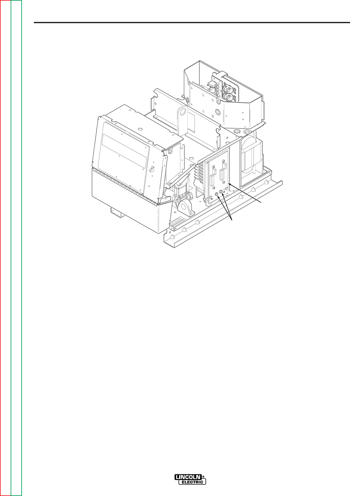
F-24
TROUBLESHOOTING AND REPAIR
F-24
POWER WAVE 455/POWER FEED 10
6. Using the high wattage resistor (25-
1000 ohms @ 25 watts (minimum),
electrically insulated gloves and pliers,
connect the resistor across the two
capacitor terminals. Hold the resistor in
place for 10 seconds. DO NOT
TOUCH THE CAPACITOR TERMI-
NALS WITH YOUR BARE HANDS.
NEVER USE A SHORTING STRAP
FOR THIS PROCEDURE.
7. Repeat procedure for the other
capacitor.
8. Recheck the voltage across the capaci-
tor terminals. The voltage should be
zero. If any voltage remains, repeat the
discharge procedure.
NOTE: Voltage present after the discharge
has been performed is an abnormal condi-
tion and may indicate a switch board
problem.
TEST PROCEDURE
1. Remove input power to the Power
Wave 455.
2. Using the 3/8 in. nutdriver, remove the
left and right case sides.
3. Be careful not to make contact with the
capacitor terminals that are located in
the bottom center of the left and right
side switch boards. See Figure F.1.
4. Carefully check for a DC voltage at the
capacitor terminals on both boards.
Note the polarity is marked on the PC
board and also lead #19 is positive.
5. If any voltage is present, proceed to
Step #6. If no voltage is present, the
capacitors are discharged.
FIGURE F.1 — CAPACITOR DISCHARGE PROCEDURE.
CAPACITOR
TERMINALS
SWITCH
BOARD
INPUT FILTER CAPACITOR DISCHARGE PROCEDURE
(continued)
Return to Section TOC Return to Section TOC Return to Section TOC Return to Section TOC
Return to Master TOC Return to Master TOC Return to Master TOC Return to Master TOC

F-25
TROUBLESHOOTING AND REPAIR
F-25
SWITCH BOARD TEST
Service and repair should only be performed by Lincoln Electric factory trained
personnel. Unauthorized repairs performed on this equipment may result in dan-
ger to the technician or machine operator and will invalidate your factory warran-
ty. For your safety and to avoid electrical shock, please observe all safety notes
and precautions detailed throughout this manual.
If for any reason you do not understand the test procedures or are unable to per-
form the test/repairs safely, contact the Lincoln Electric service department for
technical troubleshooting assistance before you proceed. Call 216-383-2531 or
1-800-833-9353(WELD).
------------------------------------------------------------------------------------------------
TEST DESCRIPTION
This test will help determine if the “power section” of the switch boards are functioning
correctly. This test will NOT indicate if the entire PC board is functional. This resis-
tance test is preferable to a voltage test with the machine energized because these
boards can be damaged easily. In addition, it is dangerous to work on these boards
with the machine energized.
This procedure takes approximately 20 minutes to perform.
MATERIALS NEEDED
3/8 in. nutdriver
3/8 in. wrench
Analog Volt-Ohmmeter
POWER WAVE 455/POWER FEED 10
WARNING
Return to Section TOC Return to Section TOC Return to Section TOC Return to Section TOC
Return to Master TOC Return to Master TOC Return to Master TOC Return to Master TOC
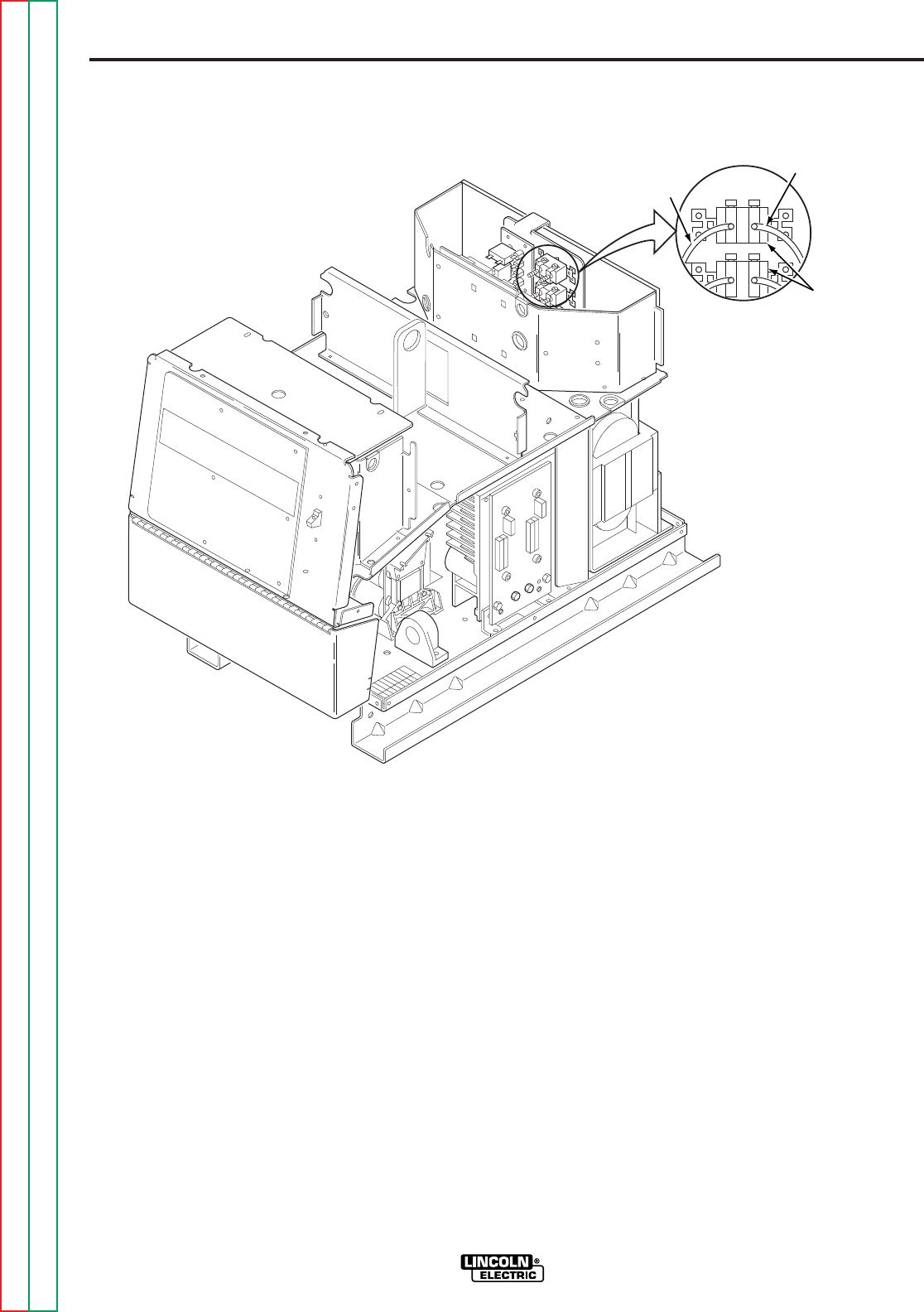
F-26
TROUBLESHOOTING AND REPAIR
F-26
POWER WAVE 455/POWER FEED 10
4. Locate label and remove leads 19C
and 19D from the reconnect switches
with the 3/8 in. wrench. Note lead
placement for reassembly. Clear leads.
Refer to Figure F.2.
5. Using the Analog ohmmeter, perform
the resistance tests detailed in Table
F.1. Refer to Figure F.3 for the test
points.
TEST PROCEDURE
1. Remove input power to the Power
Wave 455.
2. Using the 3/8 in. nutdriver, remove the
case top and sides.
3. Perform the
Capacitor Discharge
Procedure.
FIGURE F.2 — RECONNECT SWITCHES.
19C
19D
RECONNECT
SWITCHES
SWITCH BOARD TEST
(continued)
Return to Section TOC Return to Section TOC Return to Section TOC Return to Section TOC
Return to Master TOC Return to Master TOC Return to Master TOC Return to Master TOC
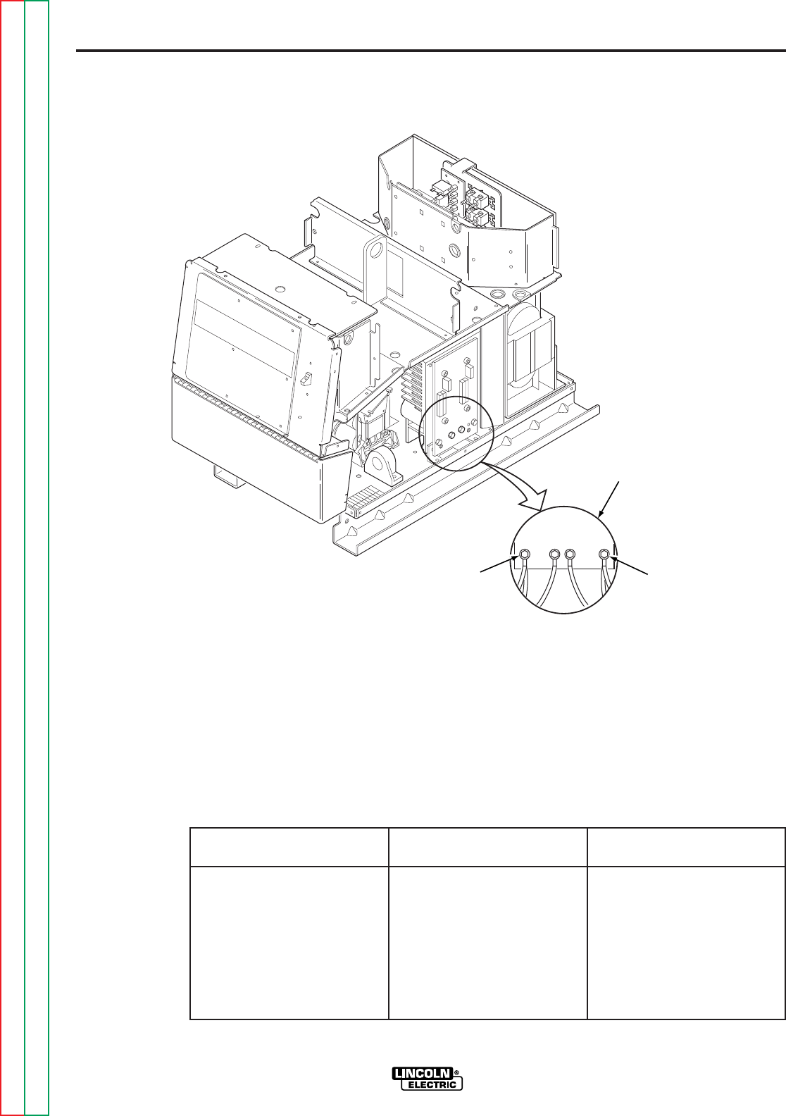
F-27
TROUBLESHOOTING AND REPAIR
F-27
POWER WAVE 455/POWER FEED 10
8. Reconnect leads 19C and 19D to the
reconnect switches. Ensure that the
leads are installed in the same location
they were removed from.
9. Install the right and left case sides
using the 3/8 in. nutdriver.
6. If any test fails replace both switch
boards. See
Switch Board Removal
and Replacement.
7. If the switch board resistance tests are
OK, check the molex pin connections
and associated wiring from the switch
boards to the control board. See wiring
diagram.
FIGURE F.3 — SWITCH BOARD TEST POINTS.
SWITCH
BOARD
-20+19
11/12
OR
15/16
13/14
OR
17/18
SWITCH BOARD TEST
(continued)
APPLY POSITIVE TEST APPLY NEGATIVE TEST NORMAL
PROBE TO TERMINAL PROBE TO TERMINAL RESISTANCE READING
+19 11/12 OR 15/16 Greater than 1000 ohms
+19 13/14 OR 17/18 Greater than 1000 ohms
11/12 OR 15/16 - 20 Greater than 1000 ohms
13/14 OR 17/18 - 20 Greater than 1000 ohms
- 20 11/12 OR 15/16 Less than 100 ohms
- 20 13/14 OR 17/18 Less than 100 ohms
11/12 OR 15/16 +19 Less than 100 ohms
13/14 OR 17/18 +19 Less than 100 ohms
TABLE F.1 — SWITCH BOARD RESISTANCE TEST.
Return to Section TOC Return to Section TOC Return to Section TOC Return to Section TOC
Return to Master TOC Return to Master TOC Return to Master TOC Return to Master TOC


F-29
TROUBLESHOOTING AND REPAIR
F-29
OUTPUT RECTIFIER TEST
Service and repair should only be performed by Lincoln Electric factory trained
personnel. Unauthorized repairs performed on this equipment may result in dan-
ger to the technician or machine operator and will invalidate your factory warran-
ty. For your safety and to avoid electrical shock, please observe all safety notes
and precautions detailed throughout this manual.
If for any reason you do not understand the test procedures or are unable to per-
form the test/repairs safely, contact the Lincoln Electric service department for
technical troubleshooting assistance before you proceed. Call 216-383-2531 or
1-800-833-9353(WELD).
------------------------------------------------------------------------------------------------
TEST DESCRIPTION
The test will help determine if any of the output rectifiers are shorted.
This procedure takes approximately 10 minutes to perform.
MATERIALS NEEDED
Analog Volt-Ohmmeter
POWER WAVE 455/POWER FEED 10
WARNING
Return to Section TOC Return to Section TOC Return to Section TOC Return to Section TOC
Return to Master TOC Return to Master TOC Return to Master TOC Return to Master TOC

F-30
TROUBLESHOOTING AND REPAIR
F-30
POWER WAVE 455/POWER FEED 10
3. With the analog ohmmeter, measure
the resistance between the positive and
negative output terminals. Refer to
Figure F.4. IMPORTANT: The positive
(+) meter probe must be attached to the
positive (+) output terminal and the
negative (-) meter probe must be
attached to the negative (-) output ter-
minal.
4. If the reading is more than 200 ohms,
the output rectifier modules are not
shorted. If the reading is less than 200
ohms, one or more of the rectifier mod-
ules are shorted. Refer to the
Output
Rectifier Module Replacement
Procedure.
TEST PROCEDURE
1. Remove main input supply power to the
Power Wave 455.
NOTE: Later code machines have a 50
ohm resistor across the welding output ter-
minals. It will be necessary to remove the
case sides and
Perform the Input Filter
Capacitor Discharge Procedure.
Remove
and insulate one of the resistor leads (#
202A or #206A) from the appropriate weld-
ing output terminal. See the wiring diagram.
2. Remove any output load that may be
connected to the Power Wave 455.
FIGURE F.4 — OUTPUT RECTIFIER TEST.
NEGATIVE (-)
OUTPUT
TERMINAL
POSITIVE (+)
OUTPUT
TERMINAL
OUTPUT RECTIFIER TEST
(continued)
Return to Section TOC Return to Section TOC Return to Section TOC Return to Section TOC
Return to Master TOC Return to Master TOC Return to Master TOC Return to Master TOC

F-31
TROUBLESHOOTING AND REPAIR
F-31
INPUT RECTIFIER TEST
Service and repair should only be performed by Lincoln Electric factory trained
personnel. Unauthorized repairs performed on this equipment may result in dan-
ger to the technician or machine operator and will invalidate your factory warran-
ty. For your safety and to avoid electrical shock, please observe all safety notes
and precautions detailed throughout this manual.
If for any reason you do not understand the test procedures or are unable to per-
form the test/repairs safely, contact the Lincoln Electric service department for
technical troubleshooting assistance before you proceed. Call 216-383-2531 or
1-800-833-9353(WELD).
------------------------------------------------------------------------------------------------
TEST DESCRIPTION
This test will help determine if the input rectifier has “shorted” or “open” diodes.
This procedure takes approximately 15 minutes to perform.
MATERIALS NEEDED
Analog Volt-Ohmmeter
Phillips head screwdriver
Wiring diagram
3/8 in. nutdriver
POWER WAVE 455/POWER FEED 10
WARNING
Return to Section TOC Return to Section TOC Return to Section TOC Return to Section TOC
Return to Master TOC Return to Master TOC Return to Master TOC Return to Master TOC
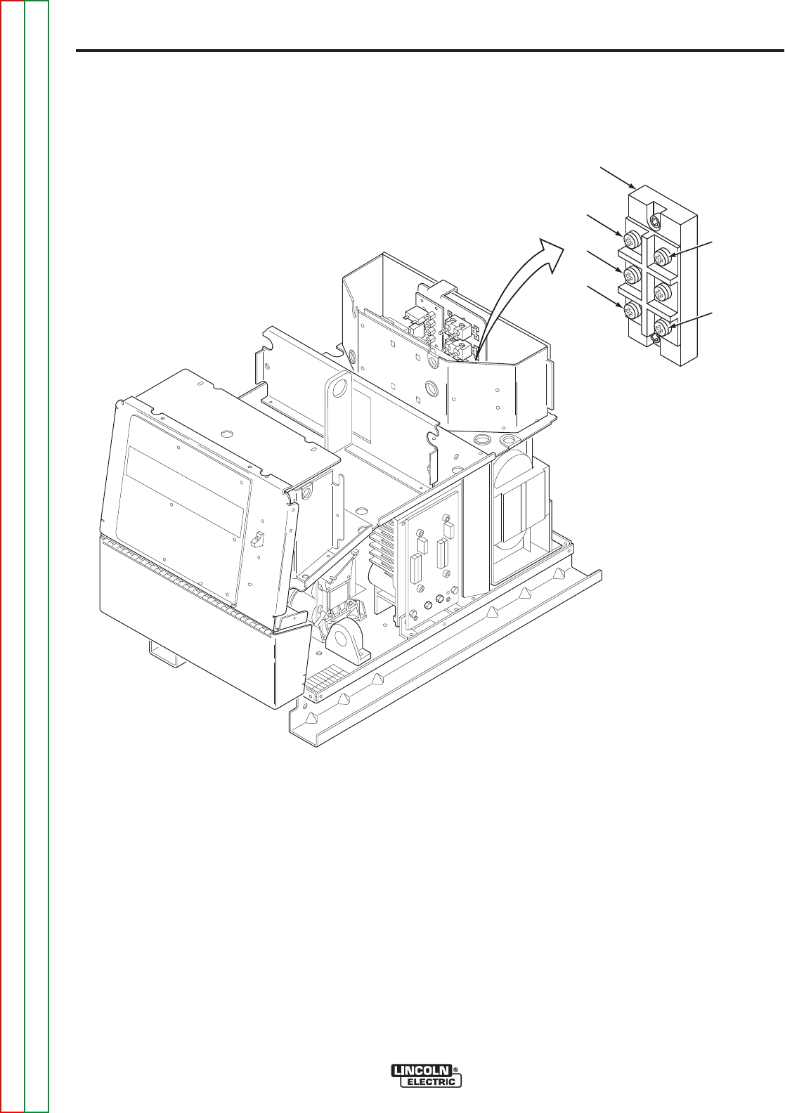
F-32
TROUBLESHOOTING AND REPAIR
F-32
POWER WAVE 455/POWER FEED 10
NOTE: Some RTV sealant may have to be
removed from the input rectifier terminals.
The RTV should be replaced when test is
complete.
5. With the Phillips head screwdriver
remove the positive and negative leads
from the rectifier.
6. Use the analog ohmmeter to perform
the tests detailed in Table F.2.
TEST PROCEDURE
1. Remove input power to the Power
Wave 455.
2. Using the 3/8 in. nutdriver, remove the
case top.
3. Perform the Capacitor Discharge
Procedure.
4. Locate the Input Rectifier and lead
locations. Refer to Figure F.5.
FIGURE F.5 — INPUT RECTIFIER TEST.
NEG (-)
POS (+)
C
B
A
INPUT
RECTIFIER
INPUT RECTIFIER TEST (continued)
Return to Section TOC Return to Section TOC Return to Section TOC Return to Section TOC
Return to Master TOC Return to Master TOC Return to Master TOC Return to Master TOC

F-33
TROUBLESHOOTING AND REPAIR
F-33
POWER WAVE 455/POWER FEED 10
9. If the input rectifier is good, be sure to
reconnect the positive and negative
leads to the correct terminals and
torque to 31 in/lbs. See wiring diagram.
10. Replace any RTV sealant previously
removed.
11. Install the case top.
7. If the input rectifier does not meet the
acceptable readings outlined in the
table, the component may be faulty.
Replace.
NOTE: Before replacing the input rectifier,
perform the
Switch Board Test
and the
Input Contactor Test.
8. When installing a new input rectifier,
see
Input Rectifier Removal and
Replacement
procedure.
TABLE F.2 — INPUT RECTIFIER TEST POINTS AND ACCEPTABLE READINGS.
INPUT RECTIFIER TEST
(continued)
TEST POINT TERMINALS ANALOG METER X10 RANGE
+ Probe - Probe Acceptable Meter Readings
A NEG Greater than 1000 ohms
B NEG Greater than 1000 ohms
C NEG Greater than 1000 ohms
A POS Less than 100 ohms
B POS Less than 100 ohms
C POS Less than 100 ohms
NEG A Less than 100 ohms
NEG B Less than 100 ohms
NEG C Less than 100 ohms
POS A Greater than 1000 ohms
POS B Greater than 1000 ohms
POS C Greater than 1000 ohms
Return to Section TOC Return to Section TOC Return to Section TOC Return to Section TOC
Return to Master TOC Return to Master TOC Return to Master TOC Return to Master TOC


F-35
TROUBLESHOOTING AND REPAIR
F-35
INPUT CONTACTOR TEST
Service and repair should only be performed by Lincoln Electric factory trained
personnel. Unauthorized repairs performed on this equipment may result in dan-
ger to the technician or machine operator and will invalidate your factory warran-
ty. For your safety and to avoid electrical shock, please observe all safety notes
and precautions detailed throughout this manual.
If for any reason you do not understand the test procedures or are unable to per-
form the test/repairs safely, contact the Lincoln Electric service department for
technical troubleshooting assistance before you proceed. Call 216-383-2531 or
1-800-833-9353(WELD).
------------------------------------------------------------------------------------------------
TEST DESCRIPTION
This test will help determine if the input contactor is functional and if the contacts are
functioning correctly.
This procedure takes approximately 17 minutes to perform.
MATERIALS NEEDED
3/8 in. nutdriver
Volt-Ohmmeter
External 24 VAC supply
POWER WAVE 455/POWER FEED 10
WARNING
Return to Section TOC Return to Section TOC Return to Section TOC Return to Section TOC
Return to Master TOC Return to Master TOC Return to Master TOC Return to Master TOC
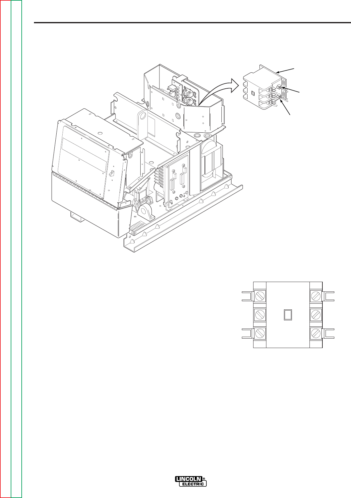
F-36
TROUBLESHOOTING AND REPAIR
F-36
POWER WAVE 455/POWER FEED 10
FIGURE F.7 — INPUT CONTACTOR
TEST POINTS.
6. When the contactor is NOT activated,
the resistance should be infinite or very
high across the contacts. If the resis-
tance is low, the input contactor is
faulty.
7. Reconnect the four leads (601, 601A,
X4, and X4A) to the input contactor coil.
8. Install the input access door and case
top using the 3/8 in. nutdriver.
TEST PROCEDURE
1. Remove input power to the Power
Wave 455.
2. Using the 3/8 in. nutdriver, remove the
input access panel and case top.
3. Locate, mark, and remove the four
leads (601, 601A, X4 and X4A) that are
connected to the input contactor coil.
Refer to Figure F.6.
4. Using the external 24 VAC supply,
apply 24 VAC to the terminals of the
input contactor coil. If the contactor
does NOT activate, the input contactor
is faulty. Replace.
5. With the input contactor activated,
check the continuity across the three
sets of contacts. (Zero ohms or very
low resistance is normal). Refer to
Figure F.7. If the resistance is high, the
input contactor is faulty. Replace the
input contactor.
FIGURE F.6 — INPUT CONTACTOR COIL.
INPUT
CONTACTOR
X4/X4A
601/601A
INPUT CONTACTOR TEST
(continued)
L3
L2
L1
T3
T2
T1
Return to Section TOC Return to Section TOC Return to Section TOC Return to Section TOC
Return to Master TOC Return to Master TOC Return to Master TOC Return to Master TOC

F-37
TROUBLESHOOTING AND REPAIR
F-37
AUXILIARY TRANSFORMER NO. 2 TEST
Service and repair should only be performed by Lincoln Electric factory trained
personnel. Unauthorized repairs performed on this equipment may result in dan-
ger to the technician or machine operator and will invalidate your factory warran-
ty. For your safety and to avoid electrical shock, please observe all safety notes
and precautions detailed throughout this manual.
If for any reason you do not understand the test procedures or are unable to per-
form the test/repairs safely, contact the Lincoln Electric service department for
technical troubleshooting assistance before you proceed. Call 216-383-2531 or
1-800-833-9353(WELD).
------------------------------------------------------------------------------------------------
TEST DESCRIPTION
This test will determine if the correct voltage is being applied to the primary of Auxiliary
Transformer No. 2 and also if the correct voltage is being induced on the secondary
winding of the transformer.
This procedure takes approximately 10 minutes to perform.
MATERIALS NEEDED
Volt-Ohmmeter (Multimeter)
3/8 in. nutdriver
Wiring diagram
POWER WAVE 455/POWER FEED 10
WARNING
Return to Section TOC Return to Section TOC Return to Section TOC Return to Section TOC
Return to Master TOC Return to Master TOC Return to Master TOC Return to Master TOC
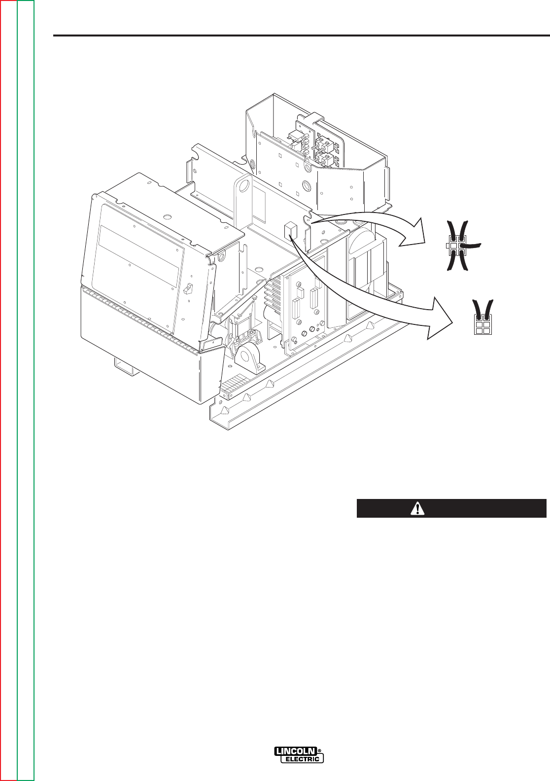
F-38
TROUBLESHOOTING AND REPAIR
F-38
POWER WAVE 455/POWER FEED 10
8. If 115 VAC is not present between pins
#1 and #4, check the associated leads
and plugs for loose or faulty connec-
tions.
High voltage is present at plug P80.
9. Carefully test for the correct AC input
voltage applied to the primary windings
at plug P80. See wiring diagram.
10. If the correct AC input voltage is
applied to the primary of the Auxiliary
Transformer No. 2 and the secondary
voltage is NOT correct, the transformer
may be faulty. Replace.
11. Install the left and right case sides
using the 3/8 in. nutdriver.
TEST PROCEDURE
1. Remove the main input supply power to
the Power Wave 455 machine.
2. Remove any load that may be connect-
ed to the 115 VAC receptacle.
3. Using the 3/8 in. nutdriver, remove the
left and right case sides.
4. Perform the
Capacitor Discharge
Procedure.
5. Locate plugs P80 and P81 at the
Auxiliary Transformer No. 2. Refer to
Figure F.8.
6. Carefully apply the correct input power
and check for 115 VAC at plug P81
pins #1 and #4.
7. If 115 VAC is present, the Auxiliary
Transformer No. 2 is good.
FIGURE F.8 — AUXILIARY TRANSFORMER NO. 2 TEST.
4
6
P80
12
3
1 4
P81
AUXILIARY TRANSFORMER NO. 2 TEST
(continued)
WARNING
Return to Section TOC Return to Section TOC Return to Section TOC Return to Section TOC
Return to Master TOC Return to Master TOC Return to Master TOC Return to Master TOC

F-39
TROUBLESHOOTING AND REPAIR
F-39
AUXILIARY TRANSFORMER NO. 1 TEST
Service and repair should only be performed by Lincoln Electric factory trained
personnel. Unauthorized repairs performed on this equipment may result in dan-
ger to the technician or machine operator and will invalidate your factory warran-
ty. For your safety and to avoid electrical shock, please observe all safety notes
and precautions detailed throughout this manual.
If for any reason you do not understand the test procedures or are unable to per-
form the test/repairs safely, contact the Lincoln Electric service department for
technical troubleshooting assistance before you proceed. Call 216-383-2531 or
1-800-833-9353(WELD).
------------------------------------------------------------------------------------------------
TEST DESCRIPTION
This test will determine if the correct voltage is being applied to the primary of Auxiliary
Transformer No. 1 and also if the correct voltage is being induced on the secondary
windings of the transformer.
This procedure takes approximately 16 minutes to perform.
MATERIALS NEEDED
Volt-Ohmmeter (Multimeter)
3/8 in. nutdriver
Wiring diagram
POWER WAVE 455/POWER FEED 10
WARNING
Return to Section TOC Return to Section TOC Return to Section TOC Return to Section TOC
Return to Master TOC Return to Master TOC Return to Master TOC Return to Master TOC
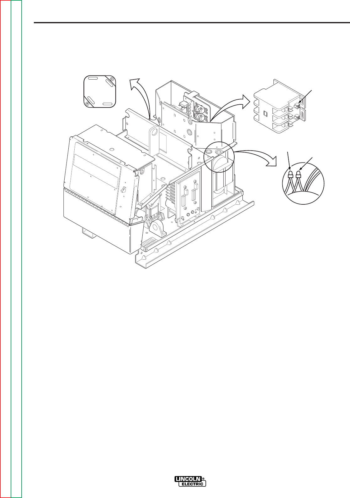
F-40
TROUBLESHOOTING AND REPAIR
F-40
POWER WAVE 455/POWER FEED 10
4. Locate secondary leads X1 and X2 (at
power board rectifier bridge). Refer to
Figure F.9.
5. Locate secondary leads X3 and X5 (fan
motor leads).
6. Locate secondary lead X4 (at main
contactor).
TEST PROCEDURE
1. Remove the main input supply power to
the Power Wave 455 machine.
2. Using the 3/8 in. nutdriver, remove the
case sides and top.
3. Perform the
Capacitor Discharge
Procedure.
FIGURE F.9 — AUXILIARY TRANSFORMER NO. 1 TEST.
FAN MOTOR
LEADS
X4
MAIN
CONTACTOR
POWER BOARD
RECTIFIER BRIDGE
X1
X2
X3 X5
AUXILIARY TRANSFORMER NO. 1 TEST
(continued)
Return to Section TOC Return to Section TOC Return to Section TOC Return to Section TOC
Return to Master TOC Return to Master TOC Return to Master TOC Return to Master TOC

F-41
TROUBLESHOOTING AND REPAIR
F-41
POWER WAVE 455/POWER FEED 10
High voltage is present at primary of
Auxiliary Transformer.
9. If the correct input voltage is applied to
the primary, and the secondary volt-
age(s) are not correct, the T1 trans-
former may be faulty.
10. Install the case sides and top using the
3/8 in. nutdriver.
7. Carefully apply the correct input voltage
to the Power Wave 455 and check for
the correct secondary voltages per
Table F.3.
NOTE: The secondary voltages will vary if
the input line voltage varies.
8. If the correct secondary voltages are
present, the T1 auxiliary transformer is
functioning properly. If any of the sec-
ondary voltages are missing or low,
check to make certain the primary is
configured correctly for the input volt-
age applied. See wiring diagram.
TABLE F.3 — SECONDARY VOLTAGES.
AUXILIARY TRANSFORMER NO. 1 TEST
(continued)
NORMAL EXPECTED
LEAD IDENTIFICATION VOLTAGE
X1 to X2 52 VAC
X3 to X5 115 VAC
X3 to X4 24 VAC
WARNING
Return to Section TOC Return to Section TOC Return to Section TOC Return to Section TOC
Return to Master TOC Return to Master TOC Return to Master TOC Return to Master TOC


F-43
TROUBLESHOOTING AND REPAIR
F-43
POWER BOARD TEST
Service and repair should only be performed by Lincoln Electric factory trained
personnel. Unauthorized repairs performed on this equipment may result in dan-
ger to the technician or machine operator and will invalidate your factory warran-
ty. For your safety and to avoid electrical shock, please observe all safety notes
and precautions detailed throughout this manual.
If for any reason you do not understand the test procedures or are unable to per-
form the test/repairs safely, contact the Lincoln Electric service department for
technical troubleshooting assistance before you proceed. Call 216-383-2531 or
1-800-833-9353(WELD).
------------------------------------------------------------------------------------------------
TEST DESCRIPTION
This test will help determine if the power board is receiving the correct voltages and
also if the power board is regulating and producing the correct DC voltages.
This procedure takes approximately 20 minutes to perform.
MATERIALS NEEDED
3/8 in. nutdriver
Volt-Ohmmeter
Wiring diagram
POWER WAVE 455/POWER FEED 10
WARNING
Return to Section TOC Return to Section TOC Return to Section TOC Return to Section TOC
Return to Master TOC Return to Master TOC Return to Master TOC Return to Master TOC
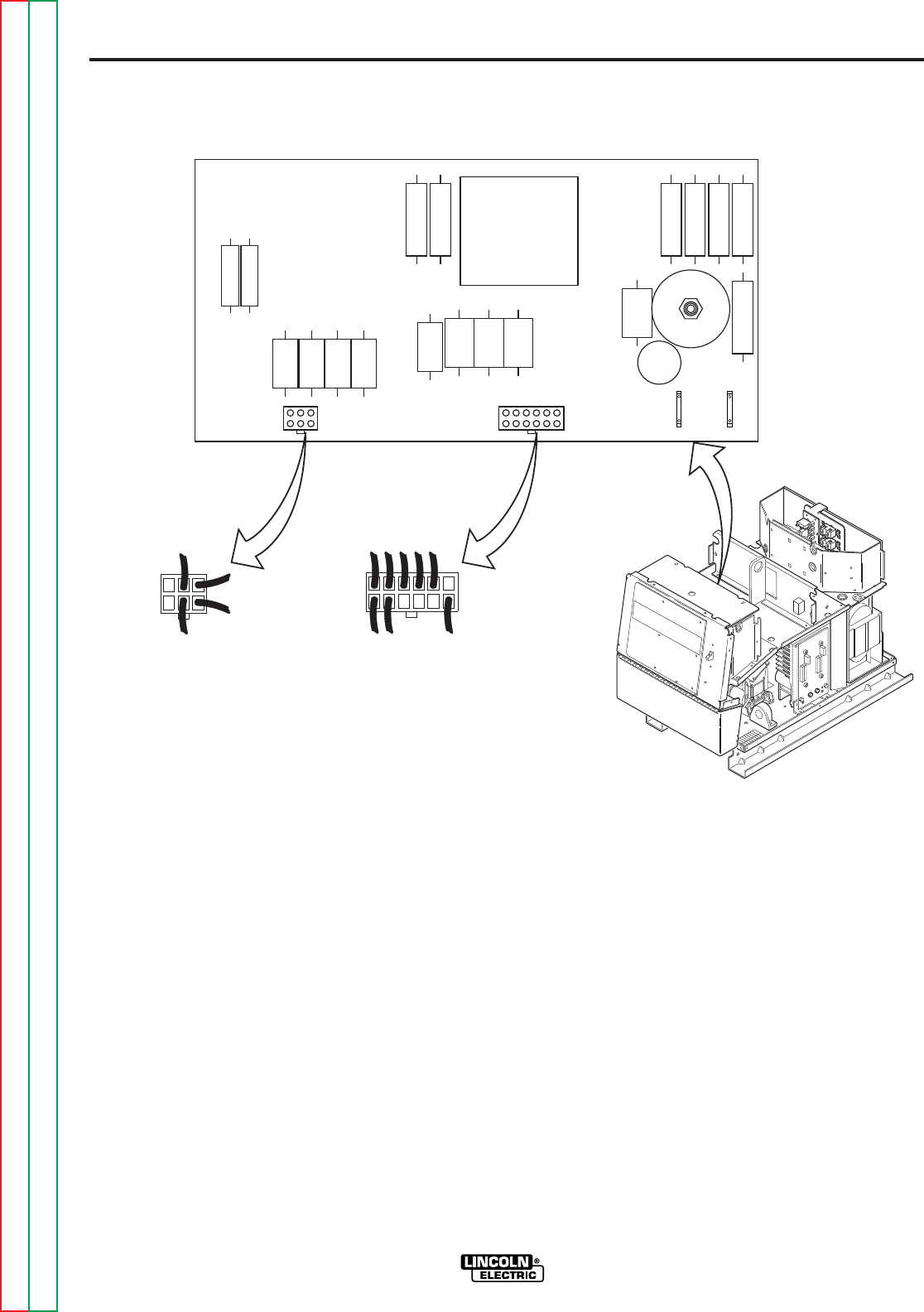
F-44
TROUBLESHOOTING AND REPAIR
F-44
POWER WAVE 455/POWER FEED 10
6. Carefully test for the correct voltages at
the power board as per Table F.4.
NOTE: Capacitor C3 (25000 mfd/100 V)
may hold a charge. Do not come in con-
tact with the capacitor terminals.
7. If the 65 VDC is low or not present at
plug J32, check the rectifier bridge and
C3 filter capacitor. See wiring diagram.
Also perform the
T1 Auxiliary
Transformer Test.
8. If any of the DC voltages are low, or not
present, at plug J31, the power board
may be faulty.
9. Install the case sides and top using the
3/8 in. nutdriver.
TEST PROCEDURE
1. Remove input power to the Power
Wave 455.
2. Using the 3/8 in. nutdriver, remove the
case sides and top.
3. Perform the
Capacitor Discharge
Procedure.
4. Locate the power board and plugs J31
and J32. Also locate leads #51 (black)
and #50 (white). Do not remove plugs
or leads from the power board. Refer
to Figure F.10.
5. Carefully apply the correct input voltage
to the Power Wave 455.
FIGURE F.10 — POWER BOARD TEST.
1 2 3 4 5
6
J31
7 89101112
J32
1
2
3
456
51
BK 50
WT
B2 B1
POWER BOARD TEST
(continued)
Return to Section TOC Return to Section TOC Return to Section TOC Return to Section TOC
Return to Master TOC Return to Master TOC Return to Master TOC Return to Master TOC
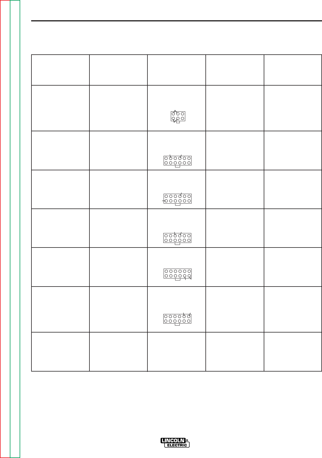
F-45
TROUBLESHOOTING AND REPAIR
F-45
POWER WAVE 455/POWER FEED 10
TABLE F.4 — POWER BOARD VOLTAGE CHECKS.
POWER BOARD TEST
(continued)
NORMAL
LEAD NO. ACCEPTABLE
CHECK POINT TEST CONNECTOR OR VOLTAGE
LOCATION DESCRIPTION PLUG PIN NO. IDENTITY READING
POWER PC CHECK 65 VDC 1 & 2(+) POS(+) 73 VDC
BOARD SUPPLY FROM 4 & 5(-) NEG(-)
CONNECTOR POWER BOARD
PLUG J32 RECTIFIER
BRIDGE
POWER PC CHECK +15 2(+) 225(+) 15 VDC
BOARD VDC SUPPLY 4(-) 222(-)
CONNECTOR FROM POWER
PLUG J31 PC BOARD
POWER PC CHECK +5 VDC 7(+) 221(+) 5 VDC
BOARD SUPPLY FROM 4(-) 222(-)
CONNECTOR POWER PC
PLUG J31 BOARD
POWER PC CHECK -15 VDC 4(+) 222(+) 15 VDC
BOARD SUPPLY FROM 3(-) 223(-)
CONNECTOR POWER PC
PLUG J31 BOARD
POWER PC CHECK +5 VDC 11(+) 274(+) 5 VDC
BOARD “CAN” SUPPLY 12(-) 273(-)
CONNECTOR FROM POWER
PLUG J31 PC BOARD
POWER PC CHECK +5 VDC 6(+) 226(+) 5 VDC
BOARD “RS232” 5(-) 228(-)
CONNECTOR SUPPLY FROM
PLUG J31 POWER PC
BOARD
POWER PC CHECK +40 #50 TERMINAL WHITE (+) 40 VDC
BOARD SPADE VDC WIRE TO BLACK (-)
TERMINALS FEEDER SUPPLY #51 TERMINAL
FROM POWER PC
BOARD
NEG
POS
225 222
221
222
223 222
274 273
228 226
Return to Section TOC Return to Section TOC Return to Section TOC Return to Section TOC
Return to Master TOC Return to Master TOC Return to Master TOC Return to Master TOC


F-47
TROUBLESHOOTING AND REPAIR
F-47
CURRENT TRANSDUCER TEST
Service and repair should only be performed by Lincoln Electric factory trained
personnel. Unauthorized repairs performed on this equipment may result in dan-
ger to the technician or machine operator and will invalidate your factory warran-
ty. For your safety and to avoid electrical shock, please observe all safety notes
and precautions detailed throughout this manual.
If for any reason you do not understand the test procedures or are unable to per-
form the test/repairs safely, contact the Lincoln Electric service department for
technical troubleshooting assistance before you proceed. Call 216-383-2531 or
1-800-833-9353(WELD).
------------------------------------------------------------------------------------------------
TEST DESCRIPTION
This test will help determine if the current transducer and associated wiring is function-
ing correctly.
This procedure takes approximately 25 minutes to perform.
MATERIALS NEEDED
3/8 in. nutdriver
Volt-Ohmmeter
POWER WAVE 455/POWER FEED 10
WARNING
Return to Section TOC Return to Section TOC Return to Section TOC Return to Section TOC
Return to Master TOC Return to Master TOC Return to Master TOC Return to Master TOC
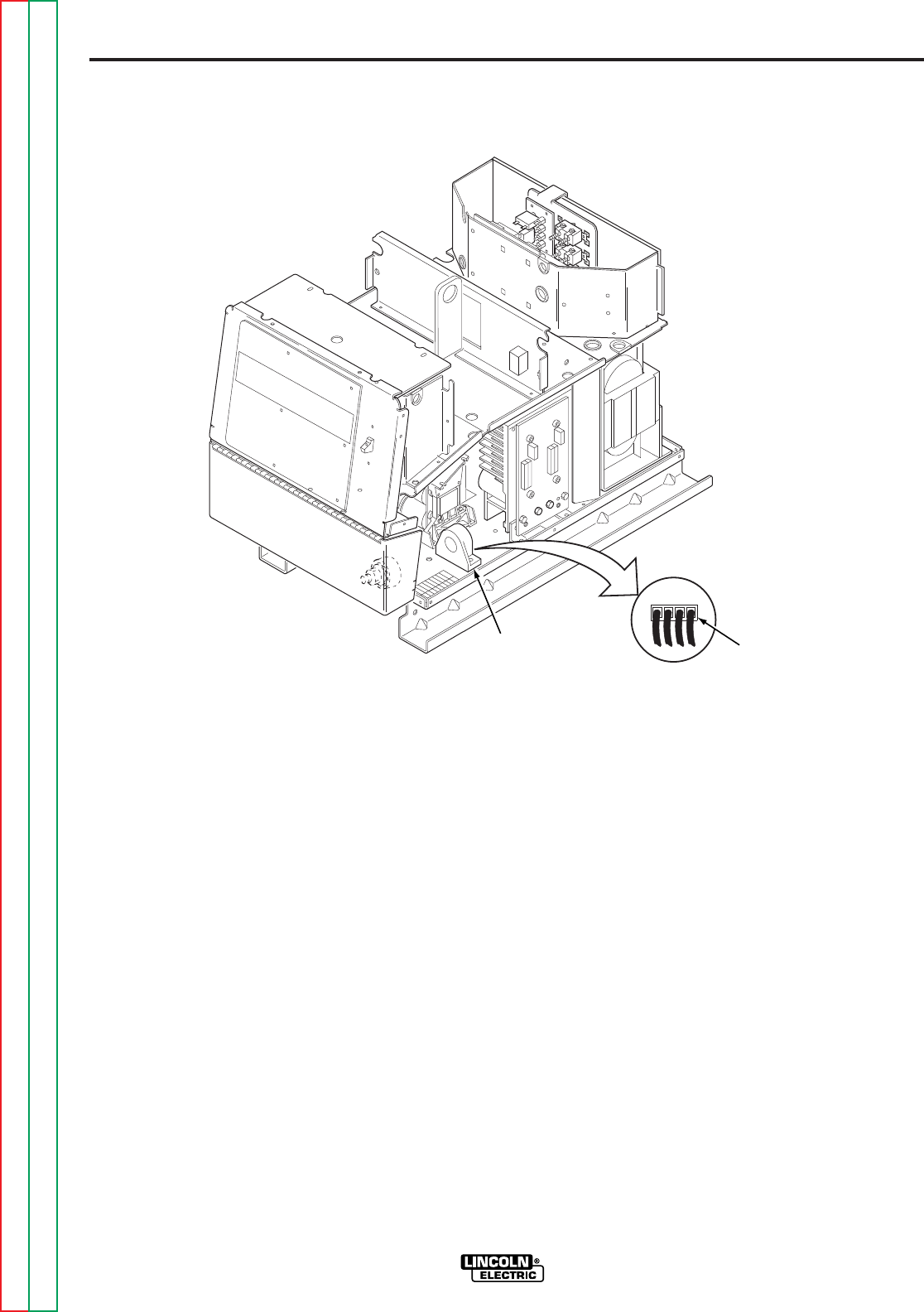
F-48
TROUBLESHOOTING AND REPAIR
F-48
POWER WAVE 455/POWER FEED 10
7. Check for the correct DC supply volt-
ages to the current transducer at plug
P90.
A. Pin 1 (lead 212+) to pin 4 (lead
216-) should read +15 VDC.
B. Pin 2 (lead 213-) to pin 4 (lead
216+) should read -15 VDC.
8. If either of the supply voltages are low
or missing, check the associated leads
between the current transducer and the
control board. If the leads are OK and
the DC supply voltages are not present,
the control board may be faulty.
TEST PROCEDURE
1. Remove input power to the Power
Wave 455.
2. Using the 3/8 in. nutdriver remove the
right side case cover.
3. Perform the
Capacitor Discharge
Procedure.
4. Locate the current transducer at the
lower right front of the machine.
5. Apply the correct input power to the
Power Wave 455.
6. Locate plug P90 at the current trans-
ducer. Do not remove the plug. Refer
to Figure F.11.
FIGURE F.11 — CURRENT TRANSDUCER TEST.
4321
P90
CURRENT
TRANSDUCER
CURRENT TRANSDUCER TEST
(continued)
Return to Section TOC Return to Section TOC Return to Section TOC Return to Section TOC
Return to Master TOC Return to Master TOC Return to Master TOC Return to Master TOC
NOTE: On later codes
the transducer is located
on left side of the
machine near the output
choke.

F-49
TROUBLESHOOTING AND REPAIR
F-49
POWER WAVE 455/POWER FEED 10
11. If the correct supply voltages are
applied to the current transducer, and
with the machine loaded, the feedback
voltage is missing or not correct, the
current transducer may be faulty. Also
make certain that lead #211 has conti-
nuity (zero ohms) between the current
transducer and the control board. See
wiring diagram.
12. Install the right side case cover using
the 3/8 in. nutdriver.
9. Check the feedback voltage from the
current transducer. With the Power
Wave system in a constant current
mode and the machine loaded to 250
amps, the current feedback voltage can
be read at plug P90.
A. Pin 3 (lead 211) to pin 4 (lead
216) should read 2.0 VDC (machine
loaded to 250 amps).
10. If for any reason the machine cannot be
loaded to 250 amps, Table F.5 shows
what feedback voltage is produced at
various current loads.
TABLE F.5 — CURRENT FEEDBACK AT VARIOUS OUTPUT LOADS.
CURRENT TRANSDUCER TEST
(continued)
EXPECTED TRANSDUCER FEEDBACK
OUTPUT LOAD CURRENT VOLTAGE
500 4.0
450 3.6
400 3.2
350 2.8
300 2.4
250 2.0
200 1.6
150 1.2
100 0.8
Return to Section TOC Return to Section TOC Return to Section TOC Return to Section TOC
Return to Master TOC Return to Master TOC Return to Master TOC Return to Master TOC


F-51
TROUBLESHOOTING AND REPAIR
F-51
DRIVE MOTOR TEST
Service and repair should only be performed by Lincoln Electric factory trained
personnel. Unauthorized repairs performed on this equipment may result in dan-
ger to the technician or machine operator and will invalidate your factory warran-
ty. For your safety and to avoid electrical shock, please observe all safety notes
and precautions detailed throughout this manual.
If for any reason you do not understand the test procedures or are unable to per-
form the test/repairs safely, contact the Lincoln Electric service department for
technical troubleshooting assistance before you proceed. Call 216-383-2531 or
1-800-833-9353(WELD).
------------------------------------------------------------------------------------------------
TEST DESCRIPTION
This test will help determine if the wire drive motor is receiving the correct voltage, and
if it is capable of running properly.
This procedure takes approximately 12 minutes to perform.
MATERIALS NEEDED
3/8 in. nutdriver
Volt-Ohmmeter
POWER WAVE 455/POWER FEED 10
WARNING
Return to Section TOC Return to Section TOC Return to Section TOC Return to Section TOC
Return to Master TOC Return to Master TOC Return to Master TOC Return to Master TOC
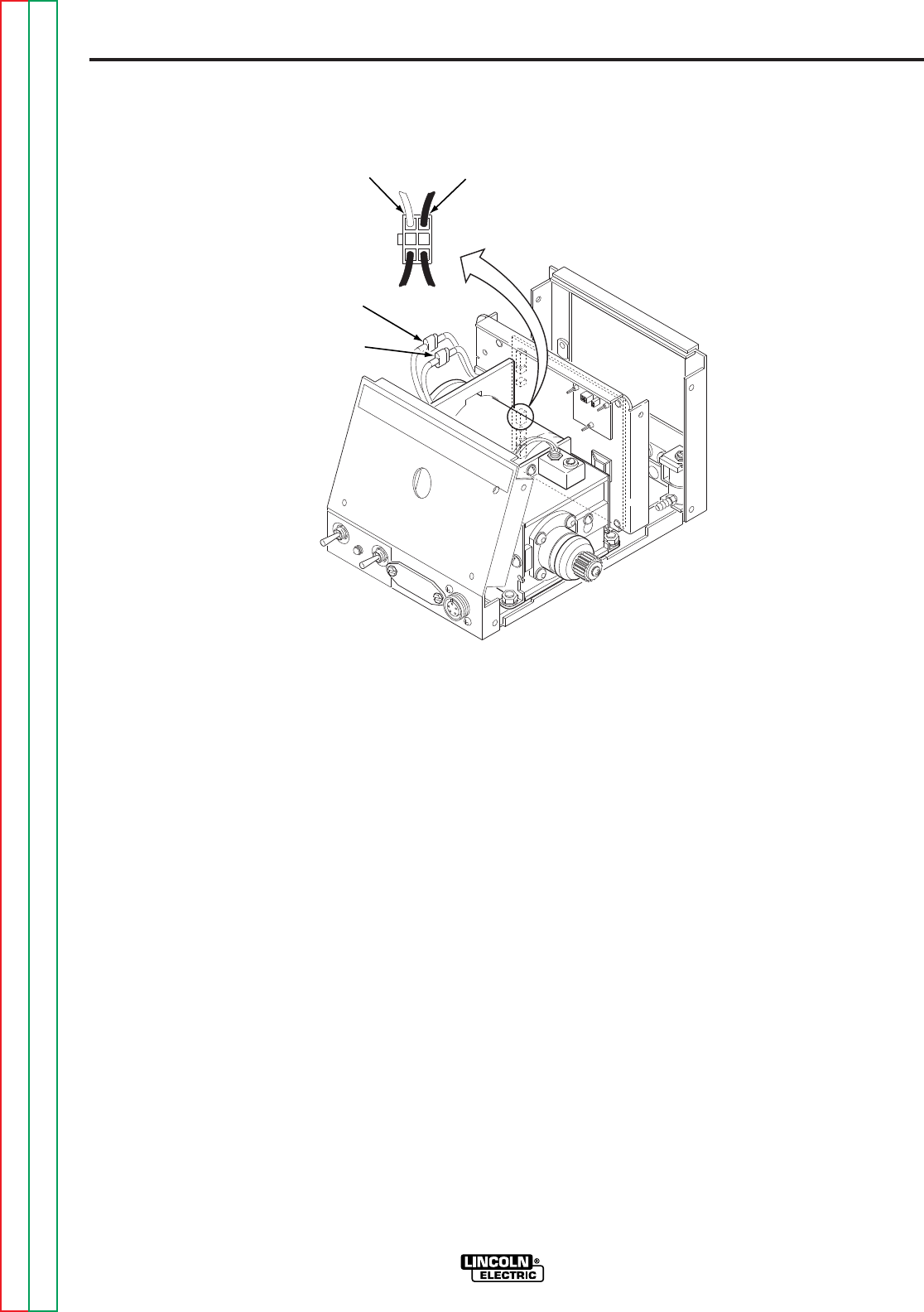
F-52
TROUBLESHOOTING AND REPAIR
F-52
POWER WAVE 455/POWER FEED 10
5. If the correct voltages are NOT present
at the motor leads, check the associat-
ed leads between the motor and plug
J3 on the control board. If the leads
are OK, the control board may be
faulty.
6. If the correct voltages are present at
the motor armature leads and the motor
does not run and vary speed with
changes in armature voltage, the motor
or gear box may be faulty. See
Gear
Box and Drive Motor Removal and
Replacement.
7. Install the wire feeder cover using the
3/8 in. nutdriver.
PROCEDURE
1. Remove input power to wire feed unit.
2. Using the 3/8 in. nutdriver, remove the
cover from the wire feeder.
3. Locate the two quick connectors in the
two motor armature leads. Refer to
Figure F.12. Do NOT disconnect the
leads.
4. Apply the correct input power (from the
Power Wave 455 control cable) to the
wire feeder. Activate the gun trigger
and with the motor running check at the
quick connectors [#551 White (+) to
#550 Black (-)] for approximately 1
VDC to 32 VDC dependent upon motor
speed. The motor speed should vary
with changes in motor armature
voltage.
FIGURE F.12 — DRIVE MOTOR TEST.
#550 (-)
BLACK
#551 (+)
WHITE
1
3
4
6
J3
#550#551
DRIVE MOTOR TEST
(continued)
Return to Section TOC Return to Section TOC Return to Section TOC Return to Section TOC
Return to Master TOC Return to Master TOC Return to Master TOC Return to Master TOC

F-53
TROUBLESHOOTING AND REPAIR
F-53
TACH FEEDBACK TEST
Service and repair should only be performed by Lincoln Electric factory trained
personnel. Unauthorized repairs performed on this equipment may result in dan-
ger to the technician or machine operator and will invalidate your factory warran-
ty. For your safety and to avoid electrical shock, please observe all safety notes
and precautions detailed throughout this manual.
If for any reason you do not understand the test procedures or are unable to per-
form the test/repairs safely, contact the Lincoln Electric service department for
technical troubleshooting assistance before you proceed. Call 216-383-2531 or
1-800-833-9353(WELD).
------------------------------------------------------------------------------------------------
TEST DESCRIPTION
This test will determine if the tach unit is receiving the correct supply voltage from the
control board, and also if the tach unit is sending feedback information to the control
board.
This procedure takes approximately 7 minutes to perform.
MATERIALS NEEDED
3/8 in. nutdriver
Volt-Ohmmeter
POWER WAVE 455/POWER FEED 10
WARNING
Return to Section TOC Return to Section TOC Return to Section TOC Return to Section TOC
Return to Master TOC Return to Master TOC Return to Master TOC Return to Master TOC
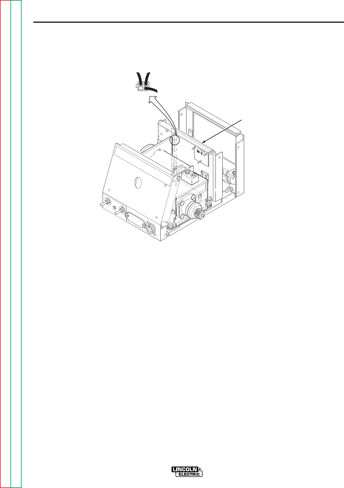
F-54
TROUBLESHOOTING AND REPAIR
F-54
POWER WAVE 455/POWER FEED 10
5. With the gun trigger activated and the
motor running, check the feedback volt-
age at plug J4 pin #2 (blue wire) posi-
tive to pin #3 (black wire) negative.
Normal feedback voltage is approxi-
mately 5 VDC. If the correct supply volt-
age is present and the feedback volt-
age is missing, the tach unit may be
faulty. With the motor NOT running,
the feedback voltage may be either 0 or
10 VDC depending upon where the
motor stopped.
6. Remove input power from the wire
feeder unit.
7. Install the wire feeder cover with the 3/8
in. nutdriver.
TEST PROCEDURE
1. Remove input power from the wire
feeder unit.
2. Using the 3/8 in. nutdriver, remove the
cover from the wire feeder.
3. Locate plug J4 on the control board.
Refer to Figure F.13. Do NOT remove
the plug from the control board.
4. Apply the correct input power (from the
Power Wave 455 control cable) to the
wire feeder unit and check for approxi-
mately 12 VDC from pin #1 (red wire)
positive to pin #3 (black wire) negative.
This is the supply voltage from the con-
trol board to the tach feedback unit. If
the 12 VDC is missing or not correct,
the wire feeder control board may be
faulty. Also check for loose or faulty
wires and connections.
FIGURE F.13 — TACH FEEDBACK TEST.
WIRE FEED
CONTROL BOARD
#3
BLACK #1
RED
#2
(BLUE)
J4
TACH FEEDBACK TEST
(continued)
Return to Section TOC Return to Section TOC Return to Section TOC Return to Section TOC
Return to Master TOC Return to Master TOC Return to Master TOC Return to Master TOC

F-55
TROUBLESHOOTING AND REPAIR
F-55
VOLTAGE SENSE PC BOARD TEST
Service and repair should only be performed by Lincoln Electric factory trained
personnel. Unauthorized repairs performed on this equipment may result in dan-
ger to the technician or machine operator and will invalidate your factory warran-
ty. For your safety and to avoid electrical shock, please observe all safety notes
and precautions detailed throughout this manual.
If for any reason you do not understand the test procedures or are unable to per-
form the test/repairs safely, contact the Lincoln Electric service department for
technical troubleshooting assistance before you proceed. Call 216-383-2531 or
1-800-833-9353(WELD).
------------------------------------------------------------------------------------------------
TEST DESCRIPTION
This test will help determine if the voltage sensing board is receiving the correct activa-
tion signal from the control board and also if the voltage sensing board is processing
arc voltage sensing information.
This procedure takes approximately 13 minutes to perform.
MATERIALS NEEDED
3/8 in. nutdriver
Volt-Ohmmeter
POWER WAVE 455/POWER FEED 10
WARNING
Return to Section TOC Return to Section TOC Return to Section TOC Return to Section TOC
Return to Master TOC Return to Master TOC Return to Master TOC Return to Master TOC
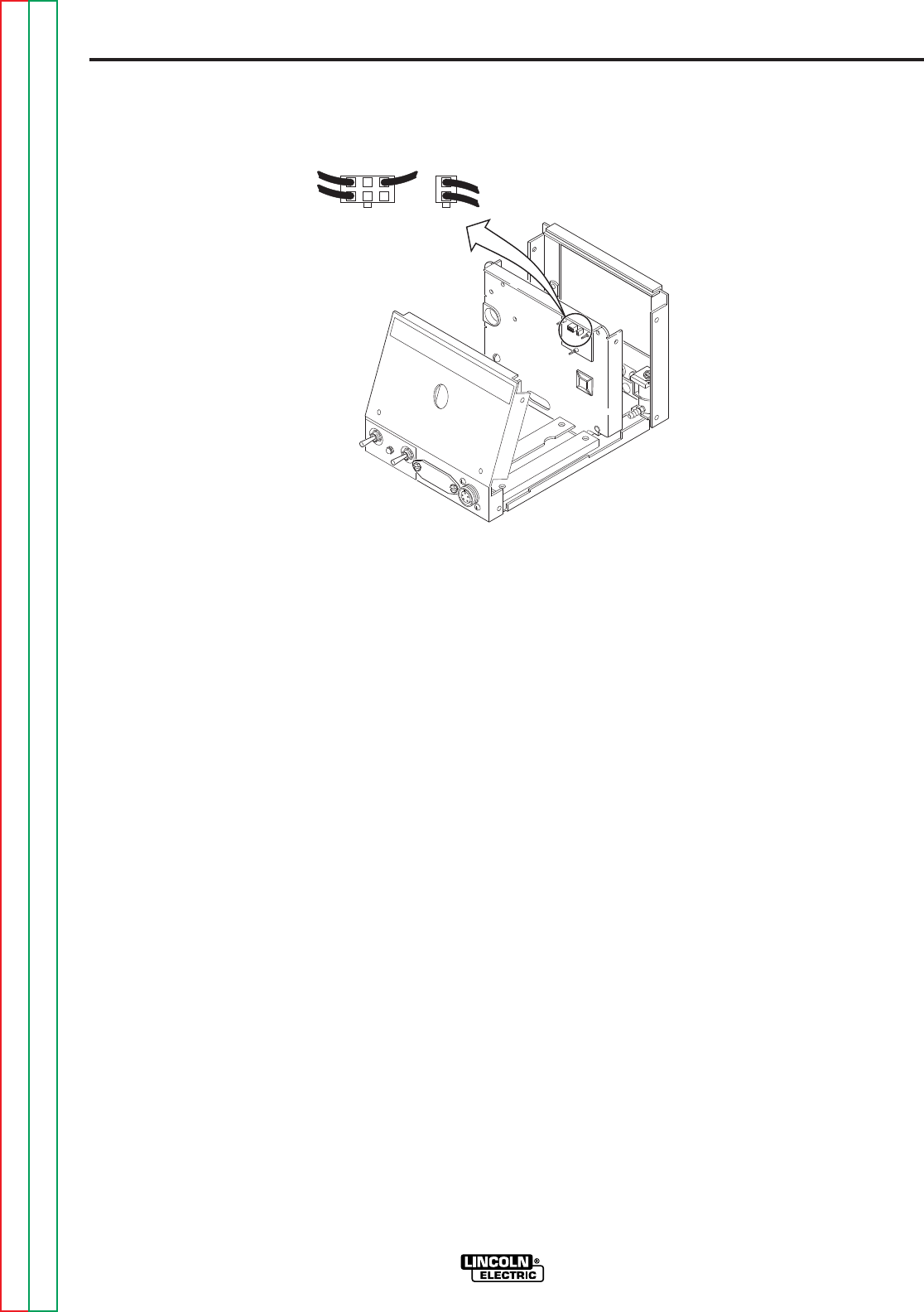
F-56
TROUBLESHOOTING AND REPAIR
F-56
POWER WAVE 455/POWER FEED 10
5. With the gun trigger activated and arc
voltage present at the conductor block,
check for arc voltage from plug J1 pin 3
(lead 67) to the workpiece. If actual
arc voltage is NOT present, check the
continuity of lead 67 from the conductor
block to plug J1 pin 3 on the voltage
sense PC board.
6. If the actual arc voltage IS present at
plug J1 pin 3 (lead 67), then check for
arc voltage from plug J2 pin 1 (lead
67A) to the workpiece. See wiring dia-
gram.
7. If the 12 VDC IS present in Step #4 and
the arc voltage IS present in Step #5
but the arc voltage is NOT present in
Step #6 (lead 67A), the voltage sense
PC board may be faulty.
8. Remove all input power from the wire
feeder unit.
9. Install the wire feeder cover with the 3/8
in. nutdriver.
TEST PROCEDURE
1. Remove input power from the wire feed
unit.
2. Using the 3/8 in. nutdriver, remove the
cover from the wire feeder.
3. Locate the voltage sense PC board and
plugs J1 and J2. Do not remove the
plugs from the voltage sense PC board.
Refer to Figure F.14.
4. Apply the correct input power (from the
Power Wave 455 control cable) to the
wire feeder. With the gun trigger acti-
vated, check for approximately 12 VDC
at plug J1 pin 1 (+) to pin 4 (-). If the 12
VDC is NOT present, the control board
may be faulty. Also check for loose or
faulty wires and connections between
the control board (plug J6) and plug J1
on the voltage sense PC board.
FIGURE F.14 — VOLTAGE SENSING BOARD TEST.
1 2 3
4561
2
J1
J2
VOLTAGE SENSE PC BOARD TEST
(continued)
Return to Section TOC Return to Section TOC Return to Section TOC Return to Section TOC
Return to Master TOC Return to Master TOC Return to Master TOC Return to Master TOC
NOTE: Inspect the molex
plug connector pins on the
Voltage Sense Board. If
any of them are gold plat-
ed the P.C. board should
be replaced

F-57
TROUBLESHOOTING AND REPAIR
F-57
DUAL ENCODER PC BOARD TEST
Service and repair should only be performed by Lincoln Electric factory trained
personnel. Unauthorized repairs performed on this equipment may result in dan-
ger to the technician or machine operator and will invalidate your factory warran-
ty. For your safety and to avoid electrical shock, please observe all safety notes
and precautions detailed throughout this manual.
If for any reason you do not understand the test procedures or are unable to per-
form the test/repairs safely, contact the Lincoln Electric service department for
technical troubleshooting assistance before you proceed. Call 216-383-2531 or
1-800-833-9353(WELD).
------------------------------------------------------------------------------------------------
TEST DESCRIPTION
This test will help determine if the encoder PC board is functioning properly.
This procedure takes approximately 20 minutes to perform.
MATERIALS NEEDED
Phillips head screwdriver
Volt-Ohmmeter (Analog Recommended)
POWER WAVE 455/POWER FEED 10
WARNING
Return to Section TOC Return to Section TOC Return to Section TOC Return to Section TOC
Return to Master TOC Return to Master TOC Return to Master TOC Return to Master TOC
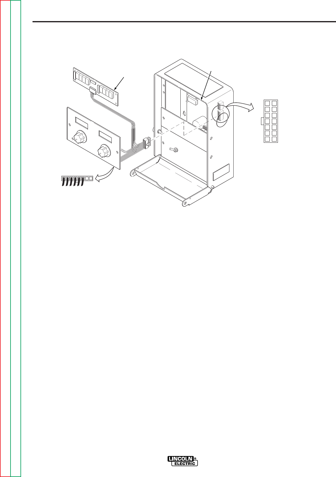
F-58
TROUBLESHOOTING AND REPAIR
F-58
POWER WAVE 455/POWER FEED 10
6. While rotating the wire feed speed
(WFS) control check for a “pulsing” 0
to 5 VDC signal at plug J1 pin 5 + (lead
553) to J1 pin 1 - (lead 500C). Also
check for a “pulsing” 0 to 5 VDC signal
from plug J1 pin 6 + (lead 554) to J1 pin
1 - (lead 500C).
7. While rotating the volts/trim control
check for a “pulsing” 0 to 5 VDC signal
at plug J1 pin 3 + (lead 555) to J1 pin 1-
(lead 500C). Also check for a “pulsing”
0 to 5 VDC signal at plug J1 pin 4 +
(lead 556) to J1 pin 1 - (lead 500C).
8. If the 12 VDC supply in Step 5 is pre-
sent and any of the 0 to 5 VDC “puls-
ing”* signals are missing, the encoder
PC board may be faulty.
*“Pulsing” means that as the control is
rotated the signal will fluctuate from 0
to 5 VDC.
9. Remove input power to the control box
assembly.
10. Install the display/encoder assembly
panel into the Control Box.
TEST PROCEDURE
1. Remove input power from control box
assembly.
2. Using the Phillips head screwdriver,
remove the display/encoder assembly
panel from the Control Box. Refer to
Figure F.15.
NOTE: The panel assembly cannot be
removed completely without removing the
lead plug from the control board. DO NOT
remove the lead plug.
3. Locate the dual encoder PC board and
plug J1. Also locate plug J4 on the
control board.
4. Apply the correct input power (from the
Power Wave 455 control cable) to the
Control Box.
5. Check for approximately 12 VDC from
plug J1 pin 2+ (lead 512C) to plug J1
pin 1 - (lead 500C). This is the supply
voltage from the control board to the
encoder board. If this voltage is miss-
ing, check the continuity of the leads
between the control board (J4) and the
encoder board (J1). See wiring dia-
gram. The control board may be faulty.
FIGURE F.15 — DUAL ENCODER TEST.
DISPLAY
BOARD
CONTROL
BOARD
J1 1 23 4 5 678
1
2
3
4
5
6
7
8
9
10
11
12
13
14
DUAL ENCODER PC BOARD TEST
(continued)
Return to Section TOC Return to Section TOC Return to Section TOC Return to Section TOC
Return to Master TOC Return to Master TOC Return to Master TOC Return to Master TOC

F-59
TROUBLESHOOTING AND REPAIR
F-59
CONTROL CABLE CONTINUITY TEST
Service and repair should only be performed by Lincoln Electric factory trained
personnel. Unauthorized repairs performed on this equipment may result in dan-
ger to the technician or machine operator and will invalidate your factory warran-
ty. For your safety and to avoid electrical shock, please observe all safety notes
and precautions detailed throughout this manual.
If for any reason you do not understand the test procedures or are unable to per-
form the test/repairs safely, contact the Lincoln Electric service department for
technical troubleshooting assistance before you proceed. Call 216-383-2531 or
1-800-833-9353(WELD).
------------------------------------------------------------------------------------------------
TEST DESCRIPTION
This test will help determine if the control cable is functional.
This procedure takes approximately 6 minutes to perform.
MATERIALS NEEDED
Volt-Ohmmeter
POWER WAVE 455/POWER FEED 10
WARNING
Return to Section TOC Return to Section TOC Return to Section TOC Return to Section TOC
Return to Master TOC Return to Master TOC Return to Master TOC Return to Master TOC

F-60
TROUBLESHOOTING AND REPAIR
F-60
POWER WAVE 455/POWER FEED 10
feeder/Control Box end. Refer to Figure
F.16 and Table F-6.
4. If any conductor resistance measures
greater than 1.0 ohm, the cable is
faulty and should be replaced. If the
resistance between any two conductors
or any conductor and the amphenol
body is less than 0.5M ohms, the cable
is faulty and should be replaced.
5. Connect the control cable amphenols to
the wire feeder and power source.
TEST PROCEDURE
1. Disconnect the input power to the
Power Wave 455 machine.
2. Disconnect the control cable amphe-
nols from the power source and the
wire feeder.
3. Using the ohmmeter measure the resis-
tance of the individual control cable
leads from the amphenol on the power
source end to the amphenol on the wire
FIGURE F.16 — CABLE CONTINUITY TEST.
WIRE FEEDER END POWER SOURCE END
A
BC
D
EE
A
B
C
D
CONTROL CABLE CONTINUITY TEST
(continued)
TABLE F.6 CONTROL CABLE PIN AND LEAD DESIGNATIONS.
FIVE PIN AMPHENOL AT FIVE PIN AMPHENOL AT
POWER SOURCE END WIRE FEEDER/CONTROL BOX END
A A
B B
C C
D D
E E
Return to Section TOC Return to Section TOC Return to Section TOC Return to Section TOC
Return to Master TOC Return to Master TOC Return to Master TOC Return to Master TOC

F-61
TROUBLESHOOTING AND REPAIR
F-61
GAS SOLENOID REMOVAL AND REPLACEMENT
Service and repair should only be performed by Lincoln Electric factory trained
personnel. Unauthorized repairs performed on this equipment may result in dan-
ger to the technician or machine operator and will invalidate your factory warran-
ty. For your safety and to avoid electrical shock, please observe all safety notes
and precautions detailed throughout this manual.
If for any reason you do not understand the test procedures or are unable to per-
form the test/repairs safely, contact the Lincoln Electric service department for
technical troubleshooting assistance before you proceed. Call 216-383-2531 or
1-800-833-9353(WELD).
------------------------------------------------------------------------------------------------
DESCRIPTION
This will aid the technician in the removal and replacement of the gas solenoid.
This procedure takes approximately 12 minutes to perform.
MATERIALS NEEDED
3/8 in. nutdriver
Needlenose pliers
5/16 in. nutdriver
3/4 in. wrench
POWER WAVE 455/POWER FEED 10
WARNING
COMPONENT REPLACEMENT PROCEDURES
Return to Section TOC Return to Section TOC Return to Section TOC Return to Section TOC
Return to Master TOC Return to Master TOC Return to Master TOC Return to Master TOC
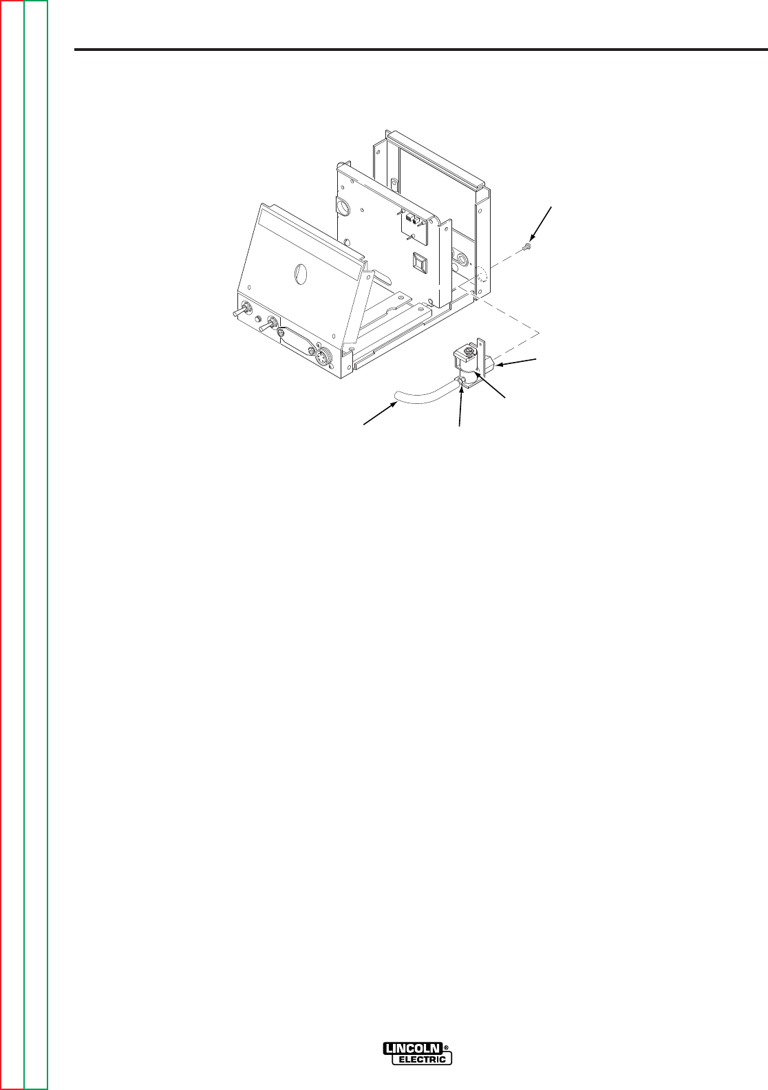
F-62
TROUBLESHOOTING AND REPAIR
F-62
POWER WAVE 455/POWER FEED 10
INSTALLATION
1. If a new solenoid is to be installed, it
may be necessary to remove the hose
fitting from the “old” solenoid and install
it into the new solenoid using the 1/2 in.
wrench.
2. Place the gas solenoid into the wire
feeder and secure it to the rear case
panel using the two 5/16 in. mounting
screws.
3. Install the gas hose onto the solenoid.
4. Connect the two electrical leads to the
gas solenoid.
5. Install the external brass fitting onto the
gas solenoid using the 3/4 in. wrench.
6. Install the wire feeder cover with the 3/8
in. nutdriver.
PROCEDURE
1. Remove input power to the wire feeder.
2. Using the 3/8 in. nutdriver, remove the
cover from the wire feeder.
3. Locate the gas solenoid on the rear
panel of the wire feeder. Refer to
Figure F.17.
4. Using the 3/4 in. wrench, remove the
external brass fitting.
5. Carefully remove the two leads from
the solenoid.
6. Remove the gas hose from the sole-
noid.
7. Using the 5/16 in. nutdriver, remove the
two screws mounting the solenoid to
the rear case panel.
8. Carefully remove the gas solenoid from
the wire feeder.
FIGURE F.17 — GAS SOLENOID REMOVAL AND REPLACEMENT.
MOUNTING
SCREW
GAS
HOSE HOSE
FITTING
BRASS
FITTING
GAS
SOLENOID
GAS SOLENOID REMOVAL AND REPLACEMENT
(continued)
Return to Section TOC Return to Section TOC Return to Section TOC Return to Section TOC
Return to Master TOC Return to Master TOC Return to Master TOC Return to Master TOC

F-63
TROUBLESHOOTING AND REPAIR
F-63
WIRE FEEDER CONTROL BOARD REMOVAL
AND REPLACEMENT
Service and repair should only be performed by Lincoln Electric factory trained
personnel. Unauthorized repairs performed on this equipment may result in dan-
ger to the technician or machine operator and will invalidate your factory warran-
ty. For your safety and to avoid electrical shock, please observe all safety notes
and precautions detailed throughout this manual.
If for any reason you do not understand the test procedures or are unable to per-
form the test/repairs safely, contact the Lincoln Electric service department for
technical troubleshooting assistance before you proceed. Call 216-383-2531 or
1-800-833-9353(WELD).
------------------------------------------------------------------------------------------------
DESCRIPTION
This will aid the technician in the removal and replacement of the control board.
This procedure takes approximately 7 minutes to complete.
MATERIALS NEEDED
3/8 in. nutdriver
Pliers
Anti-static wrist strap
POWER WAVE 455/POWER FEED 10
WARNING
Return to Section TOC Return to Section TOC Return to Section TOC Return to Section TOC
Return to Master TOC Return to Master TOC Return to Master TOC Return to Master TOC
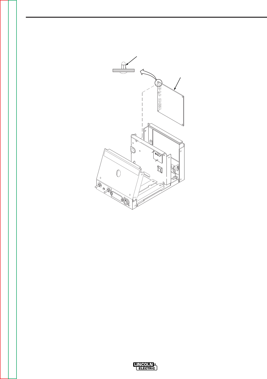
F-64
TROUBLESHOOTING AND REPAIR
F-64
POWER WAVE 455/POWER FEED 10
INSTALLATION
NOTE: Press the PC board onto the support
by pressing near the mounting hole you are
securing. Pressing near the center of the
PC board could damage the circuitry within
the board.
1. Align the holes on the PC board with
the supports attached to the wire feeder
and press the PC board until it is held
securely in place.
2. Connect the molex type plugs to the
control board.
3. Install the wire feeder cover using the
3/8 in. nutdriver.
PROCEDURE
1. Remove input power to the wire feeder.
2. Using the 3/8 in. nutdriver, remove the
cover from the wire feeder.
3. Observe static precautions detailed
in
PC Board Troubleshooting
Procedures
at the beginning of this
section.
4. Disconnect the molex type plugs from
the control board. Refer to Figure F.18.
5. Disengage the PC board supports by
squeezing each support in turn with a
pair of pliers and gently pulling out on
the board next to the support. When all
five supports have been disconnected,
carefully remove the control PC board
from the wire feeder.
FIGURE F.18 — WIRE FEEDER CONTROL BOARD REMOVAL AND REPLACEMENT.
LOCKING
TAB
WIRE FEEDER
CONTROL BOARD
WIRE FEEDER CONTROL BOARD REMOVAL AND REPLACEMENT
(continued)
Return to Section TOC Return to Section TOC Return to Section TOC Return to Section TOC
Return to Master TOC Return to Master TOC Return to Master TOC Return to Master TOC

F-65
TROUBLESHOOTING AND REPAIR
F-65
TACH (HALL EFFECT) ASSEMBLY REMOVAL
AND REPLACEMENT
Service and repair should only be performed by Lincoln Electric factory trained
personnel. Unauthorized repairs performed on this equipment may result in dan-
ger to the technician or machine operator and will invalidate your factory warran-
ty. For your safety and to avoid electrical shock, please observe all safety notes
and precautions detailed throughout this manual.
If for any reason you do not understand the test procedures or are unable to per-
form the test/repairs safely, contact the Lincoln Electric service department for
technical troubleshooting assistance before you proceed. Call 216-383-2531 or
1-800-833-9353(WELD).
------------------------------------------------------------------------------------------------
DESCRIPTION
The procedure will aid the technician in the removal and replacement of the tach
assembly from the gear box.
This procedure takes approximately 10 minutes to perform.
MATERIALS NEEDED
3/8 in. nutdriver
9/16 in. wrench
POWER WAVE 455/POWER FEED 10
WARNING
Return to Section TOC Return to Section TOC Return to Section TOC Return to Section TOC
Return to Master TOC Return to Master TOC Return to Master TOC Return to Master TOC
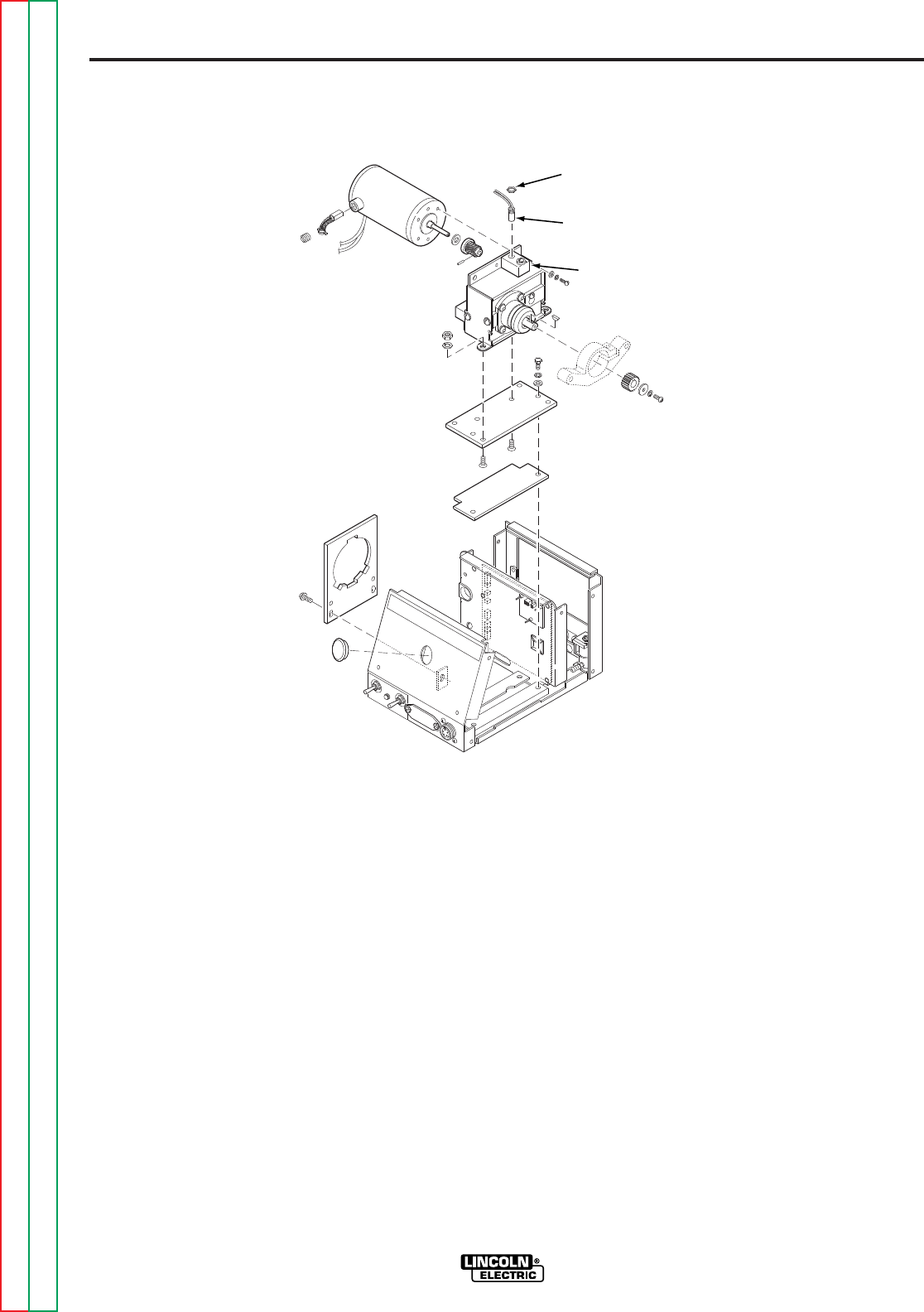
F-66
TROUBLESHOOTING AND REPAIR
F-66
POWER WAVE 455/POWER FEED 10
REPLACEMENT PROCEDURE
1. Carefully screw the Hall Effect device
into the gear box assembly until it gen-
tly “bottoms out” on the rotary magnet
inside.
2. Unscrew the Hall Effect device 1/2 turn
from the rotary magnet. Tighten the
locking nut to 8 in/lbs.
3. Thread the J4 leads through the vertical
baffle and install cable ties where
appropriate.
4. Connect plug J4 into the control board.
5. Install the wire feeder cover using the
3/8 in. nutdriver.
REMOVAL PROCEDURE
1. Remove input power to the wire feeder.
2. Using the 3/8 in. nutdriver, remove the
case cover.
3. Locate the tach assembly on the top of
the gear box. Refer to Figure F.19.
4. Locate and remove plug J4 from the
control board.
5. Thread plug J4 and associated leads
through the vertical baffle. Cut any
necessary cable ties.
6. Using the 9/16 in. wrench, loosen the
locking nut on the Hall Effect device.
7. Carefully unscrew the Hall Effect device
from the gear box assembly.
FIGURE F.19 — TACH REMOVAL AND REPLACEMENT.
LOCK
NUT
HALL
EFFECT
DEVICE
TACH
ASSEMBLY
TACH (HALL EFFECT) ASSEMBLY REMOVAL AND REPLACEMENT
(continued)
Return to Section TOC Return to Section TOC Return to Section TOC Return to Section TOC
Return to Master TOC Return to Master TOC Return to Master TOC Return to Master TOC

F-67
TROUBLESHOOTING AND REPAIR
F-67
GEAR BOX AND DRIVE MOTOR REMOVAL
AND REPLACEMENT
Service and repair should only be performed by Lincoln Electric factory trained
personnel. Unauthorized repairs performed on this equipment may result in dan-
ger to the technician or machine operator and will invalidate your factory warran-
ty. For your safety and to avoid electrical shock, please observe all safety notes
and precautions detailed throughout this manual.
If for any reason you do not understand the test procedures or are unable to per-
form the test/repairs safely, contact the Lincoln Electric service department for
technical troubleshooting assistance before you proceed. Call 216-383-2531 or
1-800-833-9353(WELD).
------------------------------------------------------------------------------------------------
DESCRIPTION
This test will aid the technican in the removal and replacement of the wire feed drive
motor.
Removal and installation of the gearbox and drive motor assembly
takes approximately 20 minutes to perform. Removal and installation
of the drive motor takes approximately 10 minutes. Removal and
installation of the gearbox takes approximately 4 minutes to complete.
MATERIALS NEEDED
3/8 in. nutdriver
Slot head screwdriver
Phillips head screwdriver
7/16 in. socket wrench with extension
Needlenose pliers
5/16 in. wrench
3/16 in. Allen wrench
POWER WAVE 455/POWER FEED 10
WARNING
Return to Section TOC Return to Section TOC Return to Section TOC Return to Section TOC
Return to Master TOC Return to Master TOC Return to Master TOC Return to Master TOC
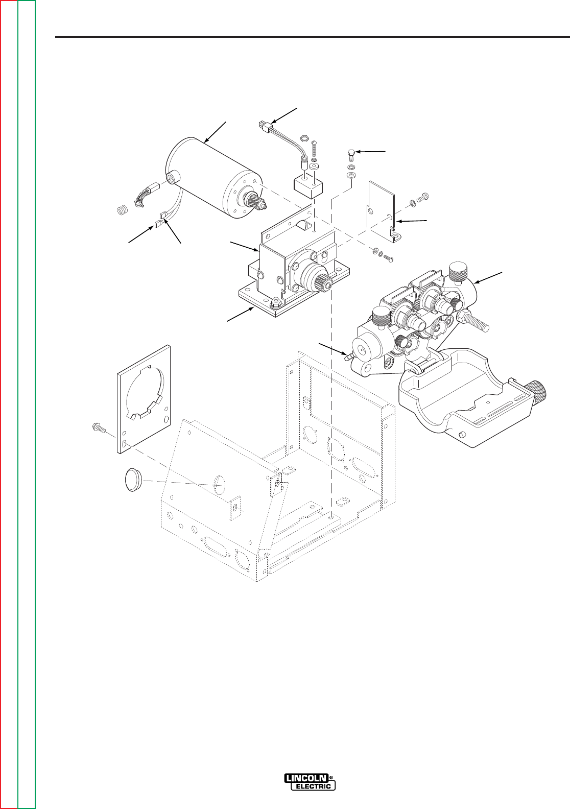
F-68
TROUBLESHOOTING AND REPAIR
F-68
POWER WAVE 455/POWER FEED 10
4. Thread plug J4 and associated leads
through the vertical baffle. Cut any
necessary cable ties.
5. Locate and disconnect the motor leads
(#551 and #550) at the quick connects.
Cut any necessary cable ties.
6. Using the Phillips head screwdriver,
remove the #67 lead from the conduc-
tor block.
PROCEDURE
1. Remove the input power to the wire
drive unit.
2. Using the 3/8 in. nutdriver, remove the
case cover.
3. Locate and remove plug J4 from the
control board. Refer to Figure F.20.
FIGURE F.20 — GEAR BOX AND DRIVE MOTOR REMOVAL AND REPLACEMENT.
DRIVE
MOTOR
#551
(BLACK) #550
(WHITE)
GEAR BOX
GAS
FITTING
WIRE
DRIVE
ASSEMBLY
INSPECTION COVER
INSULATION
MOUNTING BOLT
J4
GEAR BOX AND DRIVE MOTOR REMOVAL AND REPLACEMENT
(continued)
Return to Section TOC Return to Section TOC Return to Section TOC Return to Section TOC
Return to Master TOC Return to Master TOC Return to Master TOC Return to Master TOC

F-69
TROUBLESHOOTING AND REPAIR
F-69
POWER WAVE 455/POWER FEED 10
2. Tighten the two Allen type screws at
the bottom of the wire drive unit using
the 3/16 in. Allen wrench.
3. Attach lead #67 to the conductor block.
4. Carefully slide the drive motor into the
gear box assembly. Be sure to position
the motor leads so that they can be
properly connected.
5. Install the slot head screws that mount
the “top” of the drive motor to the gear
box.
6. Install the mounting screw located
inside the gearbox using the 5/16 in.
wrench.
7. Install the gear box inspection cover
and secure it with slot head screws.
8. Properly place insulation in the bottom
of the wire feeder case.
9. Place the entire gear box, drive motor
and wire drive assembly into the wire
feeder case, aligning the holes in the
glastic base insulator with the mounting
holes in the case.
10. Mount the gear box and drive motor
assembly to the wire feeder case using
the four mounting bolts, lock washers
and flat washers.
11. Connect the gas hose to the brass gun
connector block.
12. Connect drive motor leads #550 and
#551 to their quick disconnects.
13. Thread plug J4 and associated leads
through the vertical baffle and attach it
to the control board. Install cable ties
as necessary.
14. Install the wire feeder cover using the
3/8 in. nutdriver.
7. Using the needlenose pliers, discon-
nect the gas hose from the brass gun
connector block.
8. Using the 7/16 in. socket wrench,
remove the four mounting bolts, lock
washers, and flat washers from the
glastic base insulator.
9. Carefully slide and remove the entire
gear box, drive motor, and wire drive
assembly from the wire feeder
case. Note insulation placement for
reassembly.
TO REMOVE THE DRIVE MOTOR
FROM THE GEAR BOX:
10. Using the slot head screwdriver,
remove the gear box inspection cover
nearest to the drive motor.
11. Using the 5/16 in. wrench, remove the
motor mounting screw located inside
the gear box.
12. Using the slot head screwdriver,
remove the two screws mounting the
“top” of the motor to the gear box.
13. Carefully remove the motor from the
gear box assembly. Note motor lead
placement for reassembly.
TO REMOVE THE WIRE DRIVE
ASSEMBLY FROM THE GEAR BOX:
14. Using the 3/16 in. Allen wrench, loosen
the two Allen type screws at the bottom
of the wire drive unit.
15. Remove lead #67 from the conductor
block.
16. Carefully slide and remove the wire
drive assembly from the gear box
assembly.
REPLACEMENT PROCEDURES
1. Carefully slide the wire drive assembly
and gear box together.
GEAR BOX AND DRIVE MOTOR REMOVAL AND REPLACEMENT
(continued)
Return to Section TOC Return to Section TOC Return to Section TOC Return to Section TOC
Return to Master TOC Return to Master TOC Return to Master TOC Return to Master TOC


F-71
TROUBLESHOOTING AND REPAIR
F-71
SWITCH BOARD AND FILTER CAPACITOR REMOVAL
AND REPLACEMENT
Service and repair should only be performed by Lincoln Electric factory trained
personnel. Unauthorized repairs performed on this equipment may result in dan-
ger to the technician or machine operator and will invalidate your factory warran-
ty. For your safety and to avoid electrical shock, please observe all safety notes
and precautions detailed throughout this manual.
If for any reason you do not understand the test procedures or are unable to per-
form the test/repairs safely, contact the Lincoln Electric service department for
technical troubleshooting assistance before you proceed. Call 216-383-2531 or
1-800-833-9353(WELD).
------------------------------------------------------------------------------------------------
DESCRIPTION
This procedure will aid the technician in the removal and replacement of the switch
board(s) and/or filter capacitor(s).
This procedure takes approximately 25 minutes to perform.
MATERIALS NEEDED
3/8 in. nutdriver
7/16 in. wrench
3/16 in. Allen wrench
Slot head screwdriver
POWER WAVE 455/POWER FEED 10
WARNING
Return to Section TOC Return to Section TOC Return to Section TOC Return to Section TOC
Return to Master TOC Return to Master TOC Return to Master TOC Return to Master TOC
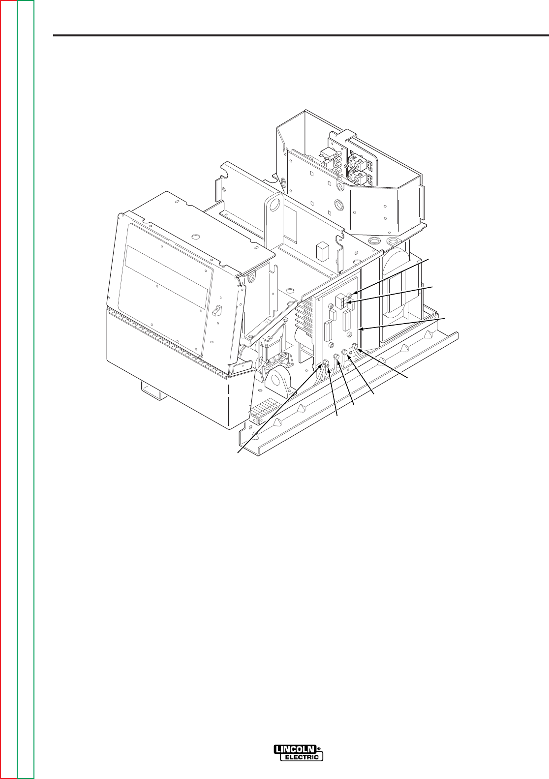
F-72
TROUBLESHOOTING AND REPAIR
F-72
POWER WAVE 455/POWER FEED 10
4. Remove the molex plug from the top of
the switch board. Refer to Figure F.21.
5. Using the 7/16 in. wrench, remove
leads 11/12 or 15/16 from the switch
board.
6. Using the 7/16 in. wrench, remove
leads 13/14 or 17/18 from the switch
board.
7. Using the 7/16 in. wrench, remove
leads 19+ and 20- from the switch
board capacitor connection bolts.
REMOVAL PROCEDURE
NOTE: Observe all static electricity precau-
tions.
1. Remove input power to the Power
Wave 455.
2. Using the 3/8 in. nutdriver, remove the
case top and sides.
3. Perform the
Capacitor Discharge
Procedure.
FIGURE F.21 — SWITCH BOARD AND FILTER CAPACITOR REMOVAL AND REPLACEMENT.
MOUNTING
SCREW (4X)
MOLEX PLUG
SWITCH
BOARD
11/12
OR
15/16
19+
20-
NYLON
SCREW
(2X)
13/14
OR
17/18
SWITCH BOARD AND FILTER CAPACITOR REMOVAL
AND REPLACEMENT
(continued)
Return to Section TOC Return to Section TOC Return to Section TOC Return to Section TOC
Return to Master TOC Return to Master TOC Return to Master TOC Return to Master TOC

F-73
TROUBLESHOOTING AND REPAIR
F-73
POWER WAVE 455/POWER FEED 10
5. Mount the new switch board and tight-
en the four cap head screws in the fol-
lowing manner.
• Tighten all until snug.
• Tighten all from 24 to 28 in/lbs.
• Tighten all from 40 to 48 in/lbs.
6. Make sure the capacitor is positioned
correctly. Connect leads 19+ and 20-
to the correct terminals. Tighten to
55 in/lbs.
7. Position and mount the two nylon
screws, fiber spacers, and washers.
Torque from 4 to 8 in/lbs.
8. Connect leads 11/12 or 15/16 to the
correct terminal.
9. Connect leads 13/14 or 17/18 to the
correct terminal.
10. Connect the molex plug to the top of
the switch board.
11. Install the case top and sides using the
3/8 in. nutdriver.
8. With the slot head screwdriver, remove
the two nylon mounting screws at the
bottom of the switch board. Note
placement of the shake-proof washers
and fiber spacers.
9. Using the 3/16 in. Allen wrench, care-
fully remove the four cap screws that
mount the switch board to the heatsink.
10. Carefully remove the switch board from
the heatsink.
11. If the filter capacitor is to be removed,
carefully slide it out of the mounting
bracket.
REPLACEMENT PROCEDURE
1. If the filter capacitor is to be replaced,
carefully slide the new capacitor into
the mounting bracket. Position the
capacitor so the correct polarity termi-
nal is lined up with the correct hole on
the switch board.
2. All heatsink and IGBT mounting sur-
faces must be clean.
3. Apply a thin coat of thermal compound
(Penetrox A13) 0.005 in. to 0.010 in. to
the mating surfaces. Do not apply
around mounting holes.
4. Apply a thin coat of Penetrox A13 to the
capacitor terminals. Be careful not to
apply compound to screw threads or
threaded area of terminals.
SWITCH BOARD AND FILTER CAPACITOR REMOVAL
AND REPLACEMENT
(continued)
Return to Section TOC Return to Section TOC Return to Section TOC Return to Section TOC
Return to Master TOC Return to Master TOC Return to Master TOC Return to Master TOC

F-74
TROUBLESHOOTING AND REPAIR
F-74
METER ACCURACY CHECK
1. With power off, locate DIP switch bank
S2 on the PF-10 Control PC board.
(There are 8 switches, number 1 on the
left, through number 8).
2. Set switch 8 to the up position.
3. Connect a resistive load between the out-
put block of the PF-10 and the work ter-
minal of the PW-455 machine.
4. Turn machine on.
5. Using the Set Control on the PF-10, set
the display to mode 200. Turn the right
knob of the PF-10 to energize the output.
6. Adjust the resistive load and the left knob
of the PF-10 to achieve 300A at 32v. The
left knob will adjust the output current.
Amps and volts will be displayed on the
PF-10 meters.
7. After the load condition is set, accuracy is
measured by comparing the meter of the
PF-10 to the master meter. At 300A,
amperage must agree within +/-10A. At
32V, voltage must agree within +/- 1V.
8. At conclusion of test, turn the power off
and set the DIP switch to its original posi-
tion.
PROCEDURE TO REPAIR IF
METERS ARE OUT OF RANGE
If the measured voltage is not within the
acceptable range, the Control PC board
must be replaced. The Control PC board
can not be calibrated.
If the measured current is not within the
acceptable current range, adjust trimmer
R126 on the Control PC board. R126 is
located on the upper left corner of the
Control PC board. If the display is still in
error, either the Control PC board or LEM
(Current Transducer) may be faulty.
Perform the
Current Transducer Test.
POWER WAVE 455/POWER FEED 10
POWER WAVE 455 / PF-10 METER ACCURACY CHECK
Service and repair should only be performed by Lincoln Electric factory trained
personnel. Unauthorized repairs performed on this equipment may result in dan-
ger to the technician or machine operator and will invalidate your factory warran-
ty. For your safety and to avoid electrical shock, please observe all safety notes
and precautions detailed throughout this manual.
If for any reason you do not understand the test procedures or are unable to per-
form the test/repairs safely, contact the Lincoln Electric service department for
technical troubleshooting assistance before you proceed. Call 216-383-2531 or
1-800-833-9353(WELD).
------------------------------------------------------------------------------------------------
DESCRIPTION
This procedure will aid the technician in checking and calibrating meter displays.
This procedure takes approximately 30 minutes to perform.
MATERIAL NEEDED
DC ammeter and meter grade shunt, +/- 1% accuracy
DC voltmeter, +/- 1% accuracy
Resistive load bank
DSP, STT or other PF-10 option panel with mode light and set switch
PW-455 and PF-10 Operator’s manual for reference
WARNING
Return to Section TOC Return to Section TOC Return to Section TOC Return to Section TOC
Return to Master TOC Return to Master TOC Return to Master TOC Return to Master TOC

F-75
TROUBLESHOOTING AND REPAIR
F-75
CONTROL OR POWER BOARD REMOVAL AND REPLACEMENT
Service and repair should only be performed by Lincoln Electric factory trained
personnel. Unauthorized repairs performed on this equipment may result in dan-
ger to the technician or machine operator and will invalidate your factory warran-
ty. For your safety and to avoid electrical shock, please observe all safety notes
and precautions detailed throughout this manual.
If for any reason you do not understand the test procedures or are unable to per-
form the test/repairs safely, contact the Lincoln Electric service department for
technical troubleshooting assistance before you proceed. Call 216-383-2531 or
1-800-833-9353(WELD).
------------------------------------------------------------------------------------------------
DESCRIPTION
This procedure will aid the technician in the removal and replacement of either the
power board or the control board.
This procedure takes approximately 15 minutes to perform.
MATERIAL NEEDED
3/8 in. nutdriver
Phillips head screwdriver
Anti-static wrist strap
POWER WAVE 455/POWER FEED 10
WARNING
Return to Section TOC Return to Section TOC Return to Section TOC Return to Section TOC
Return to Master TOC Return to Master TOC Return to Master TOC Return to Master TOC
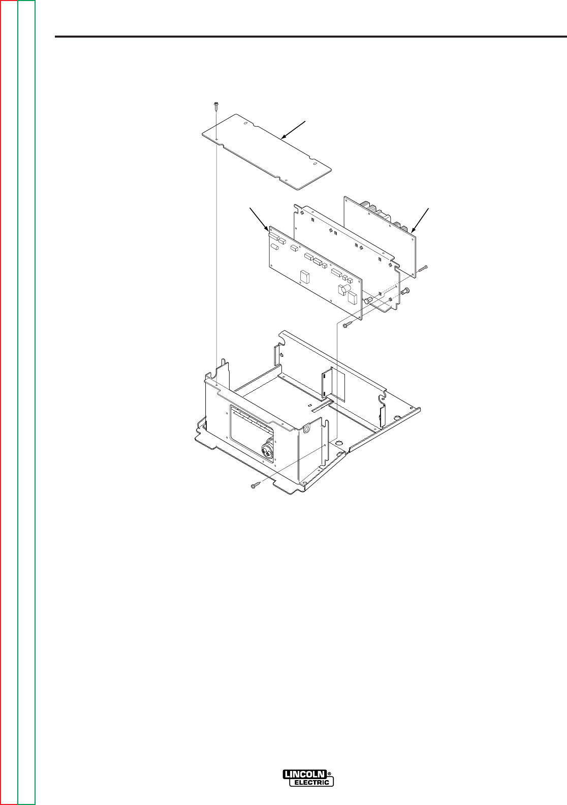
F-76
TROUBLESHOOTING AND REPAIR
F-76
POWER WAVE 455/POWER FEED 10
6. Remove the eight molex plugs from the
control board.
7. Remove the two molex plugs and white
and black wires with quick connects
from the power PC board.
8. Using the 3/8 in. nutdriver, remove the
two screws holding the rear of the
Control Box in place.
9. Clear the lead harnesses from the left
and right sides and carefully remove
the power and control PC board
assembly.
10. Using the Phillips head screwdriver,
remove either the power or the control
board from the PC board assembly.
REMOVAL PROCEDURE
1. Remove input power to the Power
Wave 455.
2. Using the 3/8 in. nutdriver, remove the
case top and sides.
3. Perform the
Capacitor Discharge
Procedure.
4. Observe all static electricity precau-
tions.
5. Using the 3/8 in. nutdriver, remove the
PC board compartment cover. Refer to
Figure F.22.
FIGURE F.22 — CONTROL OR POWER BOARD REMOVAL AND REPLACEMENT.
COMPARTMENT
COVER
POWER
BOARD
CONTROL
BOARD
CONTROL OR POWER BOARD REMOVAL AND REPLACEMENT
(continued)
Return to Section TOC Return to Section TOC Return to Section TOC Return to Section TOC
Return to Master TOC Return to Master TOC Return to Master TOC Return to Master TOC

F-77
TROUBLESHOOTING AND REPAIR
F-77
POWER WAVE 455/POWER FEED 10
4. Connect two molex plugs and black
and white wires with quick disconnects
to the power PC board.
5. Connect the eight molex plugs to the
control PC board.
6. Install the PC board compartment cover
using the 3/8 in. nutdriver.
7. Install the case top and sides using the
3/8 in. nutdriver.
INSTALLATION PROCEDURE
1. Install either the power or control board
to the PC board assembly and secure it
in place using the Phillips head mount-
ing screws.
2. Carefully slide the power and control
PC board assembly into place, making
sure to clear the lead harnesses on the
right and left side of the PC board com-
partment.
3. Secure the rear of the control box in
place using two screws and the 3/8 in.
nutdriver.
CONTROL OR POWER BOARD REMOVAL AND REPLACEMENT
(continued)
Return to Section TOC Return to Section TOC Return to Section TOC Return to Section TOC
Return to Master TOC Return to Master TOC Return to Master TOC Return to Master TOC


F-79
TROUBLESHOOTING AND REPAIR
F-79
AUXILIARY TRANSFORMER NO. 1 REMOVAL AND
REPLACEMENT PROCEDURE
Service and repair should only be performed by Lincoln Electric factory trained
personnel. Unauthorized repairs performed on this equipment may result in dan-
ger to the technician or machine operator and will invalidate your factory warran-
ty. For your safety and to avoid electrical shock, please observe all safety notes
and precautions detailed throughout this manual.
If for any reason you do not understand the test procedures or are unable to per-
form the test/repairs safely, contact the Lincoln Electric service department for
technical troubleshooting assistance before you proceed. Call 216-383-2531 or
1-800-833-9353(WELD).
------------------------------------------------------------------------------------------------
DESCRIPTION
This procedure will aid the technician in the removal and replacement of auxiliary
transformer No. 1.
This procedure takes approximately 25 minutes to perform.
MATERIALS NEEDED
3/8 in. nutdriver
Wire cutters
Wire splicer or soldering equipment
POWER WAVE 455/POWER FEED 10
WARNING
Return to Section TOC Return to Section TOC Return to Section TOC Return to Section TOC
Return to Master TOC Return to Master TOC Return to Master TOC Return to Master TOC
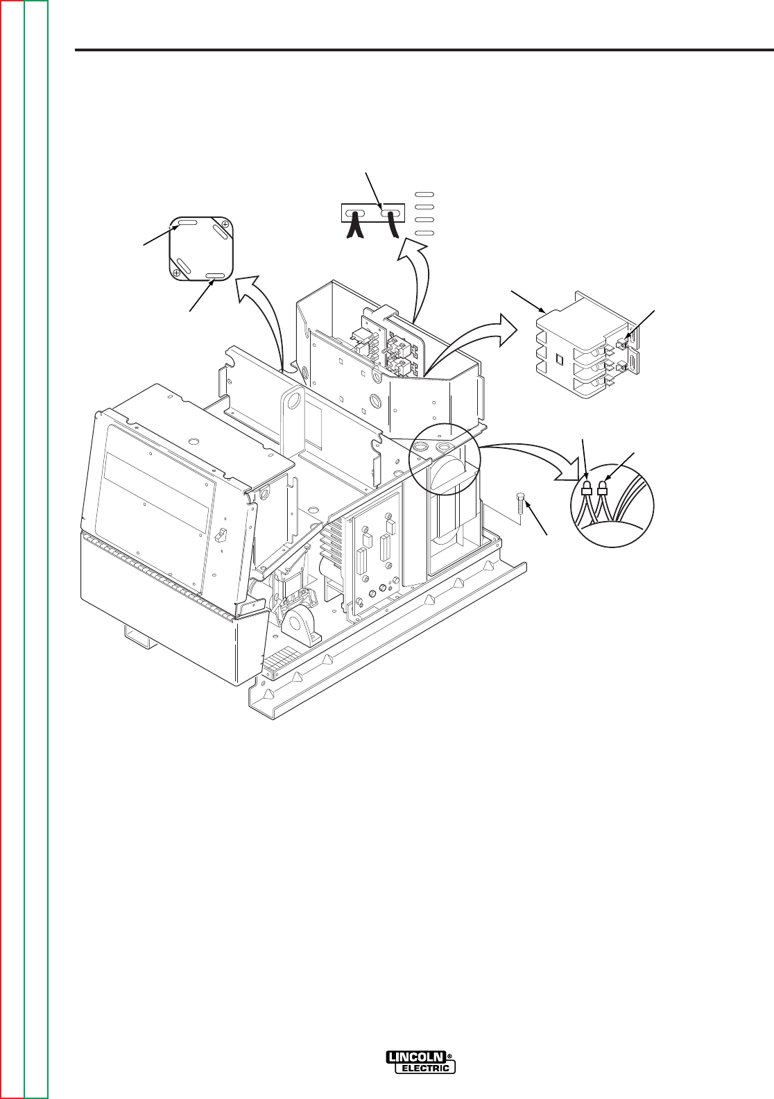
F-80
TROUBLESHOOTING AND REPAIR
F-80
POWER WAVE 455/POWER FEED 10
5. Remove leads X1 and X2 from the
power board rectifier bridge. Refer to
Figure F.23.
6. Cut X3 and X5 from the fan motor
leads. Leave enough lead length to
splice in the new transformer leads.
7. Remove lead X4 from the main contac-
tor coil terminal.
REMOVAL PROCEDURE
1. Remove input power to the Power
Wave 455.
2. Using the 3/8 in. nutdriver, remove the
case top, sides and input access panel.
3. Perform the
Capacitor Discharge
Procedure.
4. Using the 3/8 in. nutdriver, remove the
case back.
FIGURE F.23 — AUXILIARY TRANSFORMER NO. 1 REMOVAL AND REPLACEMENT PROCEDURE.
POWER BOARD
RECTIFIER BRIDGE
X1
X2
X3 X5
MOUNTING
SCREW
(2X)
FAN
MOTOR
LEADS
RECONNECT
TERMINALS
CB4
H1
H2
H3
H4
H5
MAIN
CONNECTOR
X4
AUXILIARY TRANSFORMER NO. 1 REMOVAL AND
REPLACEMENT PROCEDURE
(continued)
Return to Section TOC Return to Section TOC Return to Section TOC Return to Section TOC
Return to Master TOC Return to Master TOC Return to Master TOC Return to Master TOC

F-81
TROUBLESHOOTING AND REPAIR
F-81
POWER WAVE 455/POWER FEED 10
and the machine base using the 3/8 in.
nutdriver.
3. Install the primary leads H2, H3, H4,
and H5 to the reconnect terminals on
the reconnect panel.
4. Connect primary lead H1 to circuit
breaker CB4.
5. Splice the new transformer lead with
the X3 lead connected to the input
board.
6. Connect lead X4 to the main contactor
coil terminal.
7. Splice the new transformer fan leads to
the fan motor leads X3 and X5.
8. Connect leads X1 and X2 to the power
board rectifier bridge.
9. Reposition any wire leads and install
wire ties as necessary.
10. Install the case back using the 3/8 in.
nutdriver.
11. Install the case top, sides, and input
access panel using the 3/8 in. nutdriver.
8. Cut the X3 lead that is connected to the
input board. Leave enough lead length
to splice in the new transformer lead.
9. Locate, label, and remove primary lead
H1 from circuit breaker CB4.
10. Label and remove primary leads H2,
H3, H4, and H5 from the reconnect ter-
minals on the reconnect panel. Note
lead placement for reassembly.
11. Using the 3/8 in. nutdriver, remove the
two mounting screws that hold the
transformer to the fan baffle and the
machine base.
12. Cut any necessary cable ties and clear
the leads.
13. Carefully remove the transformer from
the Power Wave 455.
REPLACEMENT PROCEDURE
1. Carefully place the transformer into the
Power Wave 455.
2. Install the two mounting screws that
hold the transformer to the fan baffle
AUXILIARY TRANSFORMER NO. 1 REMOVAL AND
REPLACEMENT PROCEDURE
(continued)
Return to Section TOC Return to Section TOC Return to Section TOC Return to Section TOC
Return to Master TOC Return to Master TOC Return to Master TOC Return to Master TOC


F-83
TROUBLESHOOTING AND REPAIR
F-83
MAIN INPUT CONTACTOR REMOVAL AND REPLACEMENT
Service and repair should only be performed by Lincoln Electric factory trained
personnel. Unauthorized repairs performed on this equipment may result in dan-
ger to the technician or machine operator and will invalidate your factory warran-
ty. For your safety and to avoid electrical shock, please observe all safety notes
and precautions detailed throughout this manual.
If for any reason you do not understand the test procedures or are unable to per-
form the test/repairs safely, contact the Lincoln Electric service department for
technical troubleshooting assistance before you proceed. Call 216-383-2531 or
1-800-833-9353(WELD).
------------------------------------------------------------------------------------------------
DESCRIPTION
This procedure will aid the technician in the removal and replacement of the input con-
tactor.
This procedure takes approximately 15 minutes to perform.
MATERIALS NEEDED
3/8 in. nutdriver
5/16 in. nutdriver
Slot head screwdriver
POWER WAVE 455/POWER FEED 10
WARNING
Return to Section TOC Return to Section TOC Return to Section TOC Return to Section TOC
Return to Master TOC Return to Master TOC Return to Master TOC Return to Master TOC
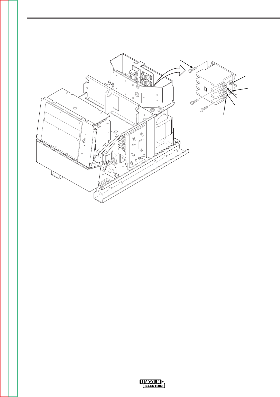
F-84
TROUBLESHOOTING AND REPAIR
F-84
POWER WAVE 455/POWER FEED 10
remove the small T2 lead. Label leads
for reassembly.
6. Remove the two small leads T1 and T3
from the quick disconnect terminals.
7. Remove leads 601, 601A, and X4, X4A
from the contactor coil terminals.
8. Remove leads L1A and L3A from the
contactor line side quick-disconnect ter-
minals.
9. Using the 5/16 in. nutdriver, remove the
three mounting screws holding the
input contactor to the metal housing
bracket.
10. Carefully remove the input contactor.
REMOVAL PROCEDURE
1. Remove input power to the Power
Wave 455.
2. Using the 3/8 in. nutdriver, remove the
case top, sides, and input access
panel.
3. Perform the
Capacitor Discharge
Procedure.
4. Using the slot head screwdriver,
remove the three input lines (L1, L2,
and L3) from the main contactor. Refer
to Figure F.24.
5. Using the slot head screwdriver,
remove the three heavy leads (T1, T2,
and T3) from the input contactor. Also
FIGURE F.24 — MAIN INPUT CONTACTOR REMOVAL AND REPLACEMENT.
MOUNTING
SCREW (3X)
L3
L2
L1
T1
T2
T3
X4/X4A
601/601A
MAIN INPUT CONTACTOR REMOVAL AND REPLACEMENT
(continued)
Return to Section TOC Return to Section TOC Return to Section TOC Return to Section TOC
Return to Master TOC Return to Master TOC Return to Master TOC Return to Master TOC

F-85
TROUBLESHOOTING AND REPAIR
F-85
POWER WAVE 455/POWER FEED 10
5. Install the two small leads T1 and T3 to
the quick-disconnect terminals.
6. Install the three input lines (L1, L2 and
L3) to the main contactor using the slot
head screwdriver.
7. Install the three heavy leads (T1, T2
and T3) from the input contactor using
the slot head screwdriver.
8. Install the small T2 lead to the input
contactor.
9. Install the case top, sides, and input
access panel using the 3/8 in. nutdriver.
REPLACEMENT PROCEDURE
1. Carefully place the input contactor into
position.
2. Install the three mounting screws that
hold the input contactor to the metal
housing bracket using the 5/16 in.
nutdriver.
3. Connect leads L1A and L3A to the
contactor line side quick-disconnect
terminals.
4. Install leads 601, 601A, and X4, X4A
to the contactor coil terminals.
MAIN INPUT CONTACTOR REMOVAL AND REPLACEMENT
(continued)
Return to Section TOC Return to Section TOC Return to Section TOC Return to Section TOC
Return to Master TOC Return to Master TOC Return to Master TOC Return to Master TOC


F-87
TROUBLESHOOTING AND REPAIR
F-87
INPUT RECTIFIER REMOVAL AND REPLACEMENT
Service and repair should only be performed by Lincoln Electric factory trained
personnel. Unauthorized repairs performed on this equipment may result in dan-
ger to the technician or machine operator and will invalidate your factory warran-
ty. For your safety and to avoid electrical shock, please observe all safety notes
and precautions detailed throughout this manual.
If for any reason you do not understand the test procedures or are unable to per-
form the test/repairs safely, contact the Lincoln Electric service department for
technical troubleshooting assistance before you proceed. Call 216-383-2531 or
1-800-833-9353(WELD).
------------------------------------------------------------------------------------------------
DESCRIPTION
This procedure will aid the technician in the removal and replacement of the input recti-
fier module.
This procedure takes approximately 15 minutes to perform.
MATERIALS NEEDED
3/8 in. nutdriver
3/16 in. Allen wrench
Phillips head screwdriver
POWER WAVE 455/POWER FEED 10
WARNING
Return to Section TOC Return to Section TOC Return to Section TOC Return to Section TOC
Return to Master TOC Return to Master TOC Return to Master TOC Return to Master TOC
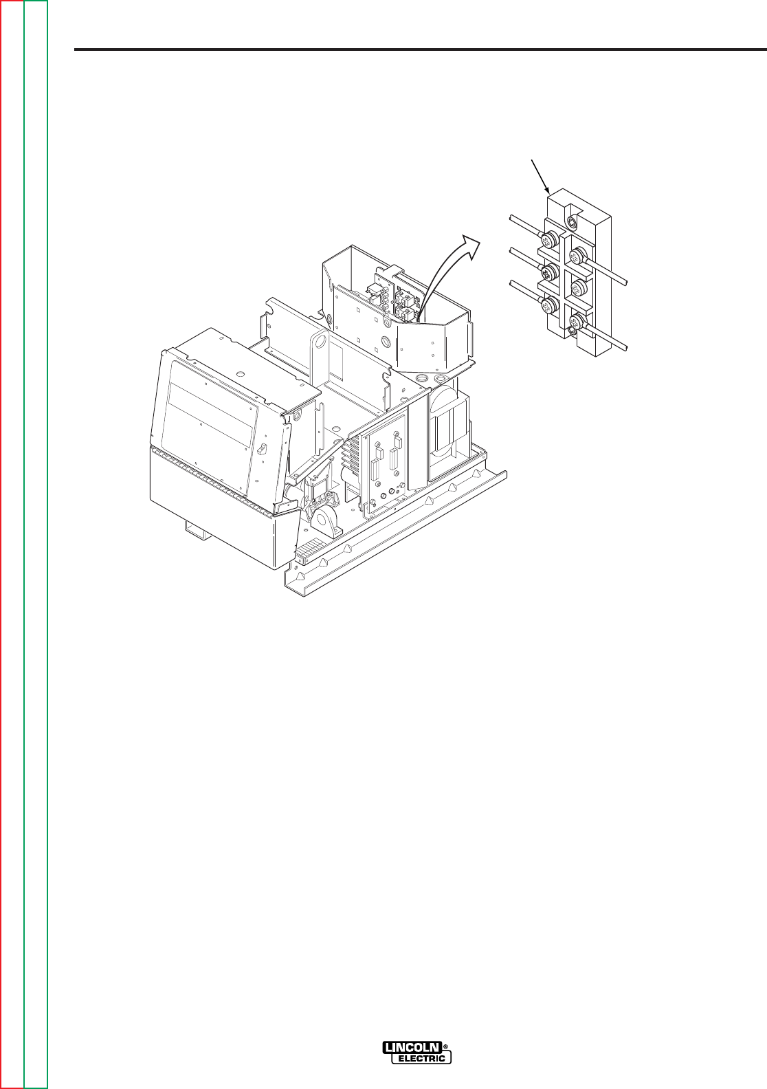
F-88
TROUBLESHOOTING AND REPAIR
F-88
POWER WAVE 455/POWER FEED 10
7. Carefully remove the module.
REPLACEMENT PROCEDURE
1. Clean heatsink surfaces.
2. Apply an even coating of joint com-
pound (Penetrox A-13) to both the
heatsink and module mounting sur-
faces. The joint compound should be
0.002 in/0.005 in. thick per surface.
3. Mount the module to the heat sink and
evenly torque the mounting screws
(with washers) to 44 in/lbs.
4. Assembly the leads to the correct mod-
ule terminals and torque to 26 in/lbs.
5. Apply RTV sealant to the rectifier con-
nection terminals.
6. Install the case top, sides, and input
access panel using the 3/8 in. nutdriver.
REMOVAL PROCEDURE
1. Remove input power to the Power
Wave 455.
2. Using the 3/8 in. nutdriver, remove the
case top, sides, and input access
panel.
3. Perform the
Capacitor Discharge
Procedure.
4. Locate and remove the RTV sealant
from the input rectifier connection termi-
nals. Refer to Figure F.25.
5. Label leads and using the Phillips head
screwdriver carefully remove the five
leads from the input rectifier terminals.
Note placement for reassembly.
6. Using the 3/16 in. Allen wrench,
remove the two mounting screws and
washers from the rectifier module.
FIGURE F.25 — INPUT RECTIFIER REMOVAL AND REPLACEMENT.
A
B
C
POS (+)
NEG (-)
INPUT
RECTIFIER
INPUT RECTIFIER REMOVAL AND REPLACEMENT
(continued)
Return to Section TOC Return to Section TOC Return to Section TOC Return to Section TOC
Return to Master TOC Return to Master TOC Return to Master TOC Return to Master TOC

F-89
TROUBLESHOOTING AND REPAIR
F-89
OUTPUT RECTIFIER AND MODULE REMOVAL
AND REPLACEMENT
Service and repair should only be performed by Lincoln Electric factory trained
personnel. Unauthorized repairs performed on this equipment may result in dan-
ger to the technician or machine operator and will invalidate your factory warran-
ty. For your safety and to avoid electrical shock, please observe all safety notes
and precautions detailed throughout this manual.
If for any reason you do not understand the test procedures or are unable to per-
form the test/repairs safely, contact the Lincoln Electric service department for
technical troubleshooting assistance before you proceed. Call 216-383-2531 or
1-800-833-9353(WELD).
------------------------------------------------------------------------------------------------
DESCRIPTION
This procedure will aid the technician in the removal and replacement of the output rec-
tifier assembly and individual rectifier module replacement.
This procedure takes approximately 35 minutes to remove and replace
the output rectifier and 5 minutes to remove and replace the rectifier
module.
MATERIALS NEEDED
3/8 in. nutdriver
7/16 in. wrench
9/16 in. wrench
9/64 in. Allen wrench
POWER WAVE 455/POWER FEED 10
WARNING
Return to Section TOC Return to Section TOC Return to Section TOC Return to Section TOC
Return to Master TOC Return to Master TOC Return to Master TOC Return to Master TOC
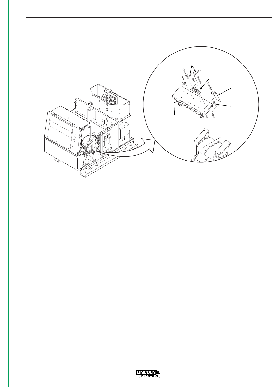
F-90
TROUBLESHOOTING AND REPAIR
F-90
POWER WAVE 455/POWER FEED 10
5. Using the 7/16 in. wrench, remove the
eight transformer leads from the rectifi-
er modules. Label the leads and take
note of lead placement for reassembly.
Note that each screw has two flat
washers and one lock washer.
6. Remove leads #220 and #290 from the
rectifier thermostat.
7. Using the 7/16 in. wrench, remove the
four nuts and associated washers from
the heatsink mounting bolts. The heat-
sink assembly can be removed by care-
fully sliding the assembly forward and
removing the mounting bolts.
RECTIFIER ASSEMBLY
REMOVAL PROCEDURE
1. Remove input power to the Power
Wave 455.
2. Using the 3/8 in. nutdriver, remove the
case top and sides.
3. Perform the
Capacitor Discharge
Procedure.
4. Using the 9/16 in. wrench, remove the
positive output lead from the rectifier
heatsink. Refer to Figure F.26.
FIGURE F.26 — OUTPUT RECTIFIER AND MODULE REMOVAL AND REPLACEMENT.
TRANSFORMER
LEADS
RECTIFIER
MODULE
THERMOSTAT
HEATSINK
HEATSINK
MOUNT
BOLTS (4X)
POSITIVE
OUTPUT
LEAD
OUTPUT RECTIFIER AND MODULE REMOVAL AND REPLACEMENT
(continued)
Return to Section TOC Return to Section TOC Return to Section TOC Return to Section TOC
Return to Master TOC Return to Master TOC Return to Master TOC Return to Master TOC

F-91
TROUBLESHOOTING AND REPAIR
F-91
POWER WAVE 455/POWER FEED 10
RECTIFIER ASSEMBLY
REPLACEMENT PROCEDURE
1. Position the assembly in place with the
mounting bolts.
2. Assemble the nuts and associated
washers to the mounting bolts.
3. Using the 7/16 in. wrench, tighten the
four nuts on the mounting bolts.
4. Replace leads #220 and #290 to the
thermostat.
5. Connect the eight transformer leads to
the correct rectifier modules. Tighten
the screws (with two flat washers and
one lock washer) to between 30 and 40
in/lbs. Do not stress the terminals
when making these connections.
6. Apply a thin coat of Penetrox A13 to the
heatsink where the positive output lead
attaches.
7. Attach the positive output lead to the
heatsink using the 9/16 in. wrench.
8. Install the case top and sides using the
3/8 in. nutdriver.
RECTIFIER MODULE REMOVAL
AND REPLACEMENT
PROCEDURE
1. Using the 9/64 in. Allen wrench,
remove the cap screw from the center
of the rectifier module that is to be
replaced.
2. Using the 7/16 in. wrench, remove the
two mounting bolts and associated
washers from the rectifier module to be
replaced.
3. Remove the faulty module.
4. This module requires special mounting
considerations to prevent warping of
the base plate. The heatsink surfaces
must be clean and flat. Apply a thin,
even coating of thermal compound,
(Penetrox A13) 0.004 to 0.010 inches
thick. Keep the compound away from
the area of the mounting holes.
5. Press the new module firmly against
the heatsink while aligning the mount-
ing holes. Start all three screws two to
three turns by hand.
6. Tighten each of the outer screws to
between 5 and 10 in/lbs.
7. Tighten the center screw to between 12
and 18 in/lbs.
8. Tighten each of the outer screws again,
this time to between 30 and 40 in/lbs.
OUTPUT RECTIFIER AND MODULE REMOVAL AND REPLACEMENT
(continued)
Return to Section TOC Return to Section TOC Return to Section TOC Return to Section TOC
Return to Master TOC Return to Master TOC Return to Master TOC Return to Master TOC

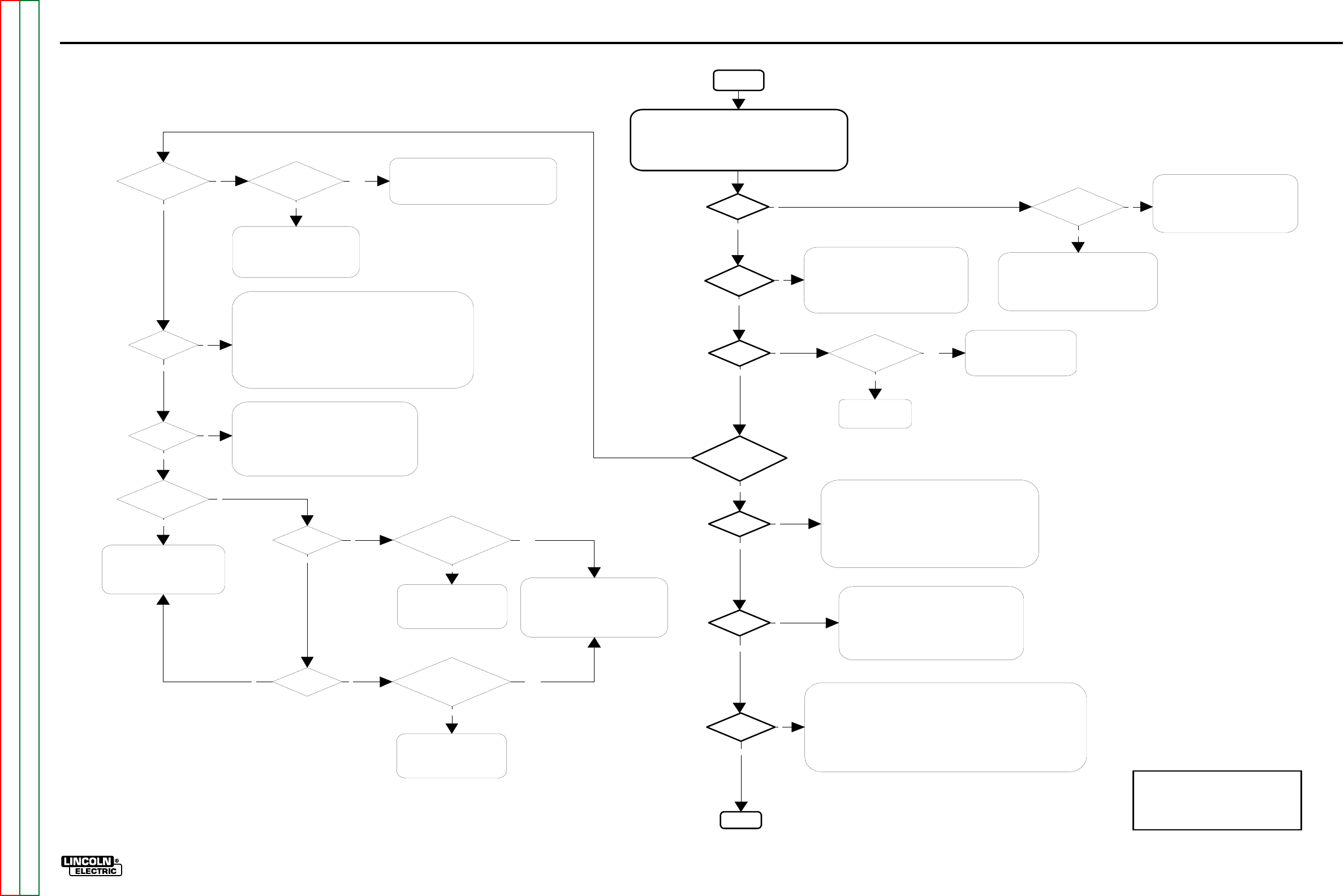
TROUBLESHOOTING AND REPAIR F-93
POWER WAVE 455/POWER FEED 10
FLOWCHART - POWER SOURCE ERROR INTERPRETATION GUIDE
Code 12?
Start
Codes 21,
22, or 23?
Code 36?
Code 31?
Codes 32, 33, 34,
and 35? UI previously recognized by the system is no
longer communicating, but power appears to
be present at the UI. Check for intermittent
connections in the communication path
(pins A and B in the control cable, wires 541
and 542 in both the UI and FH).
UI Display and
Status light on?
UI previously recognized by the system is no
longer communicating, and no power appears to
be present at the UI. Check for intermittent
connections in the +40 VDC path (pins D and E
in the control cable, wires 540 and 500 in both
the UI and FH).
Weld Table Error is present.
Reload known good Weld Software.
Check the "All Modes" dipswitch in the UI, typically
SW2-8 (refer to dipswitch settings specified for the
software version loaded in the UI).
Thermal Error (generally accompanied by a thermal error light):
Check continuity of thermostat circuit. Thermostats are connected
in series, so open circuit reading indicates tripped thermostat or
faulty connection
Check operation of the cooling fan.
Check for excessive dirt build up in heatsink fins etc.
Perform Output
Rectifier Test
Replace Output
Rectifier Modules as
Required
The current transformer (CT)
feedback signal to the control
board is too high. Look for a
short in the transformer or
primary side of the machine.
Perform the Switch
Board Test on both
sides.
Replace as Necessary.
Replacement board(s) must have
identical part number (including the
"dash number").
Code 32 and
33?
Code 34 and
35?
Both Switch boards are reporting an undervoltage error.
Check Input Voltage.
Perform the Input Board Test.
Check for proper reconnect position.
Look for faulty undervoltage connections from the Switch board(s) to the
Control board (+5VDC = normal, 0VDC = fault).
If the symptom is intermittent, Check the operation of the main contactor.
Both Switch boards are reporting an overvoltage error.
Check the Input Voltage.
Check for proper reconnect position.
Look for faulty overvoltage connections from the Switch
board(s) to the Control board
(+5VDC = normal, 0VDC = fault).
Machine configured
for 230V?
Invalid error combination. Check for
faulty overvoltage and undervoltage
connections from the Switch
board(s) to the Control board
(+5VDC = normal, 0VDC = fault).
Code 32 and
34?
Code 33 and
35?
Perform the Switch Board
Test on Side "A" (left side
facing the front of
machine)
Perform the Switch Board
Test on Side "B" (right
side facing the front of
machine)
Replace the Switch Board
Replacement board(s) must have
identical part number (including
the "dash number").
Replace the Switch
BoardReplacement board(s)
must have identical part number
(including the "dash number").
Check main capacitor for a short circuit
condition.
Check for faulty overvoltacge and
undervoltage connections from the Switch
board(s) to the Control board
(+5VDC = normal, 0VDC = fault).
N
Y
Y
Y
N
Y
YPass
Fail
Y
Fail
N
Y
Y
N
N
Y
N
Y
Fail
Pass
N
YPass
Fail
N
Any of the following
codes:
32, 33, 34, or 35?
Code 37?
Soft Start failure.
Generally accompanied by under and over voltage errors
(32-35), because the system is unable to charge the
main capacitors to an acceptable voltage level.
Follow the branch for under and over voltage errors
(32-35) to test the Input Bd., Switch Bd., and main
contactor operation.
Finish
Y
N
N
N
N
N
Power Source Error Interpretation Guide
Error codes that contain three or four digits are defined as fatal errors. These codes
generally indicate internal errors on the PS Control Board. If cycling the input power on
the machine does not clear the error, try reloading the operating system. If this fails,
replace the control board.
EXCEPTION:
Reoccuring fatal errorscan sometimes be caused by overloading the system. As an
example this could occur in earlier versions of PS software when rapidly changing from
one head to the another on a multi-head system (i.e. PF10x2). Adding a minimum (0.1
seconds) of preflow time to each head or upgrading the operating system shoudl
generally solve the problem.
Other Codes?
N
Y
(Semi Automatic PW-455, PW455/STT)
If the PS Status light is flashing any combination of red and green,
errors are present in the PW-455.
Error Code interpretation through the Status light is detailed in the
Service Manual. Individual code digits are flashed in red with a long
pause between digits. If more than one code is present, the codes
will be se
p
arated b
y
a
g
reen li
g
ht.
Key:
PS = Power Source
UI = User Interface (Control
Box)
FH = Feed Head
Perform the Contactor Test.
Perform Input Board Test.
Perform the Input Rectifier Test.
Pass
(For Codes 10555 and Below)
F-93
Return to Section TOC Return to Section TOC Return to Section TOC Return to Section TOC
Return to Master TOC Return to Master TOC Return to Master TOC Return to Master TOC
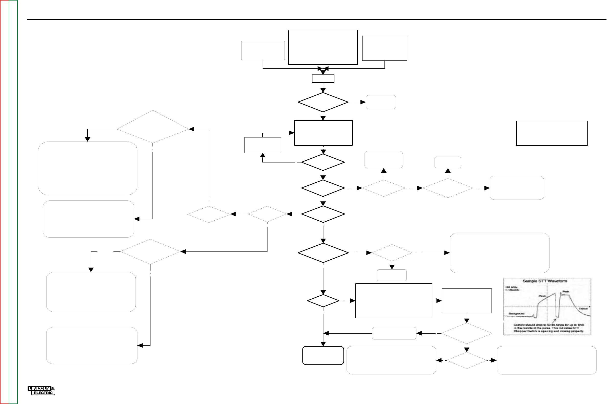
TROUBLESHOOTING AND REPAIR F-94
POWER WAVE 455/POWER FEED 10
FLOWCHART - PERFORMANCE TROUBLESHOOTING GUIDE
Turn On
Performance Test Configuration (USE STD
STUD)**
GMAW (.045 Steel - 3/8" Plate)
Mode = 5
WFS =400 ipm
Voltage = 28V
Gas =90/10 ArCO2
Arc Control= 0
** Configuration may be altered based on available
materials. A spray procedure was selected for
Alternate CC Configuration:
Grid Load (300A / 30V)
Mode = 200
Current = 300
Arc Control = 0
Alternate CV Configuration:
Grid Load (300A / 30V)
Mode = 201
Voltage = 30V
Arc Control = 0
Note: Mode 201 requires an
electrode sense lead (67).
All Status Lights green?
UI functional with no
errors displayed? FH
functional?
See Functional
Troubleshooting
Guide
Activate output (trigger the welding
output).
Using the appropiate measuring
equipment, compare the Actual Current,
Voltage, and WFS to the readings
displayed on the UI
Do you get output
from the machine
(can you weld)?
Actual vs Displayed
WFS:
+/-10 ipm?**
Actual vs Displayed
Voltage:
+/-1 Volt?**
Actual vs Displayed
Current:
+/- 10 Amps?**
Increase or Decrease the
output settings as
required to achieve a
stable output.
The system is monitoring and
controlling WFS, Voltage,
and Current correctly.
Performance checks OK.
Y
Y
Y
Y
Y
Y
N
Y
N
**Note: The accuracy of measuring equipment
plays a significant role.Generally speaking,
meters of reasonable accuracy should give
readings within the stated limits. The intent
here is to establish proper performance, not
absolute accuracy.
Motor running full
speed regardless of
WFS setting?
Does FH gear ratio
dipswitch setting match
pinion gear size?
Perform tachometer test.
Repair / replace as
necessary.
Correct FH
Dipswitch
settin
g
.
Check for proper Drive Roll tension.
Check for proper Drive Rolls.
Verify software is correct version
(PF-10 vs.PF-11).
ALL VOLTAGE MEASUREMENTS SHOULD BE MADE
AT THE SOURCE OF THE VOLTAGE FEEDBACK.
The source of voltage feedback is mode dependent. Mode
200 senses voltage from the output studs of the machine.
Modes 5 and 201 sense from the Conductor Block on the
feeder to the negative stud of the machine, unless the
Voltage Sense Plug (P26) is removed from the Control PC
Bd., inwhich case the remote work sense plug is used
instead of the negative stud.
Test being
performed in Mode
200?
Perform the Voltage
Sense PC Board Test.
Under load as defined
previously:
Check for actual voltage
at the PS
Control PC Bd., from P20-8
to P20-2
(P20
-
8to
P20-4 if usin
g
a remote work
sense lead)
The Power Source Control PC Board is interpreting voltage correctly, but
there is a bad or incorrect connection in the feedback path.
Check to make sure the weld polarity matches the Electrode Sense
Polarity dipswitch in the FH (SW-7). The default setting is electrode
positive.
Check connections in the entire electrode sense path (wire #67) from the
2 pin output connector on the Voltage Sense PC Board, through the FH
w
irin
g
harness, control cable
(
s
)
, UI wirin
g
harness
(
if s
y
stem is
configured with the UI between the FH and PS), and up to P20-8 on the
Control PC Board inside of the PS.
Check the work sense path (wire #202) from P20-2 on the PS Control PC
Board to the Work Stud, or (wire #21) from P20-4 to the remote work
sense lead depending on the configuration.
The PS Control PC Board is NOT interpreting voltage correctly.
On "-3" and higher vintage PS Control PC Boards the Voltage
feedback can be calibrated. Perform the "Voltage Calibration
Procedure".
If unable to calibrate, replace the Control PC Board. Please note the
statement regarding test meter accuracy, and follow all applicable
board replacement procedures when replacing this board.
OK
Matches Display
Value +/- 1V
Does not match
Display Value +/- 1V
NN
Under load as defined
previously: Check for actual
voltage at the PS Control PC
Bd., from P20-6 to P20-2.
The Power Source Control PC Board is interpreting voltage
correctly, but there is a bad connection in the feedback path.
Check connections in the electrode sense path (wire #206) from
P20-6 on the Control PC Board to the electrode(+) stud inside of
the PS.
Check the work sense path (wire #202) from P20-2 on the Control
PC Board to the Work Stud.
The PS Control PC Board is NOT interpreting voltage correctly.
On "-3" and higher vintage PS Control PC Boards the Voltage
feedback can be calibrated. Perform the "Voltage Calibration
Procedure".
If unable to calibrate, replace the Control PC Board. Please note the
statement regarding test meter accuracy, and follow all applicable
board replacement procedures when replacing this board.
Matches Display
Value +/- 1V
Does not match
Display Value +/- 1V
Y
Y
N N Y
N
Perform the PS
Current Transducer
Test
The PS Control PC Board is NOT interpreting current correctly.
Check the connections at P21 on the Control PC Board. Particularly the
signal pins (1 and 6).
Depending on the magnitude of the descrepency, the current feedback
can be calibrated. Perform the "Current Calibration Procedure".
If unable to calibrate, and the connections are OK, replace the Control PC
Board. Please note the statement regarding test meter accuracy, and
follow all applicable board replacement procedures when replacing this
board.
Replace the current
Transducer.
NPass
Fail
Performance Troubleshooting Guide
(Semi Automatic PW-455, PW455/STT)
Key:
PS = Power Source
UI = User Interface (Control
Box)
FH = Feed Head
STT Machine?
N
STT Performance Test Configuration (USE STT STUD)**
GMAW (.045 Steel - 1/4" Plate)
Mode = 117
WFS =170 ipm
Trim = 1.00
Gas =CO2
Arc Control= 0
** Configuration may be altered based on available
materials, but basic waveshape should remain the same.
!!CANNOT BE TESTED WITH STATIC GRID LOAD!!
Using the Arc Scope function in
Wave Designer / Wave Surfer, or
an oscilloscope equiped with a
current probe, capture an STT
waveform, and compare it to the
sample STT waveform (shown at
ri
g
ht
)
.
Are the wave shapes
similar, and does current
drop in the middle of the
pulse as indicated?
Does the machine
noodle weld ( low output)?
The STT Chopper PC Board appears to be "open".
Check for 18Vac at J10 pins 1 & 4 on the STT Chopper Board.
Check for loose or broken connections. Inspect the PC board for physical
damage
Perform the STT Chopper Board Test.
The STT Chopper PC Board appears to be shorted, and therefore,
the resulting current waveform does not drop in the middle of the
pulse as indicated in the Sample STT Waveform
Disconnect J10 from the STT Chopper PC Board, and make
another test weld. If the same symptoms result, perform the STT
chopper PCBD test. If the machine noodle welds, the problem is
related to the control signal from the Control PC Board.
The STT portion of the system
is operating properly
Y
N
Y
YN
A NOTE ON VOLTAGE SENSING:
All CV and Pulse modes utilize the electrode sense lead (lead #67) built into the control cable.
As with any sense lead it's performance is only as good as the worst connection.
For diagnostic purposes, an external sense lead can be used to bypass the entire electrode
sense network. This can be accomplished by removing the front cover of the PW-455, and
connecting a lead (20 AWG minimum) from pin 5 of the exposed 6 pin UI molex connector (P6),
to the feedplate on the feeder.
(For Codes 10555 and Below)
F-94
Return to Section TOC Return to Section TOC Return to Section TOC Return to Section TOC
Return to Master TOC Return to Master TOC Return to Master TOC Return to Master TOC
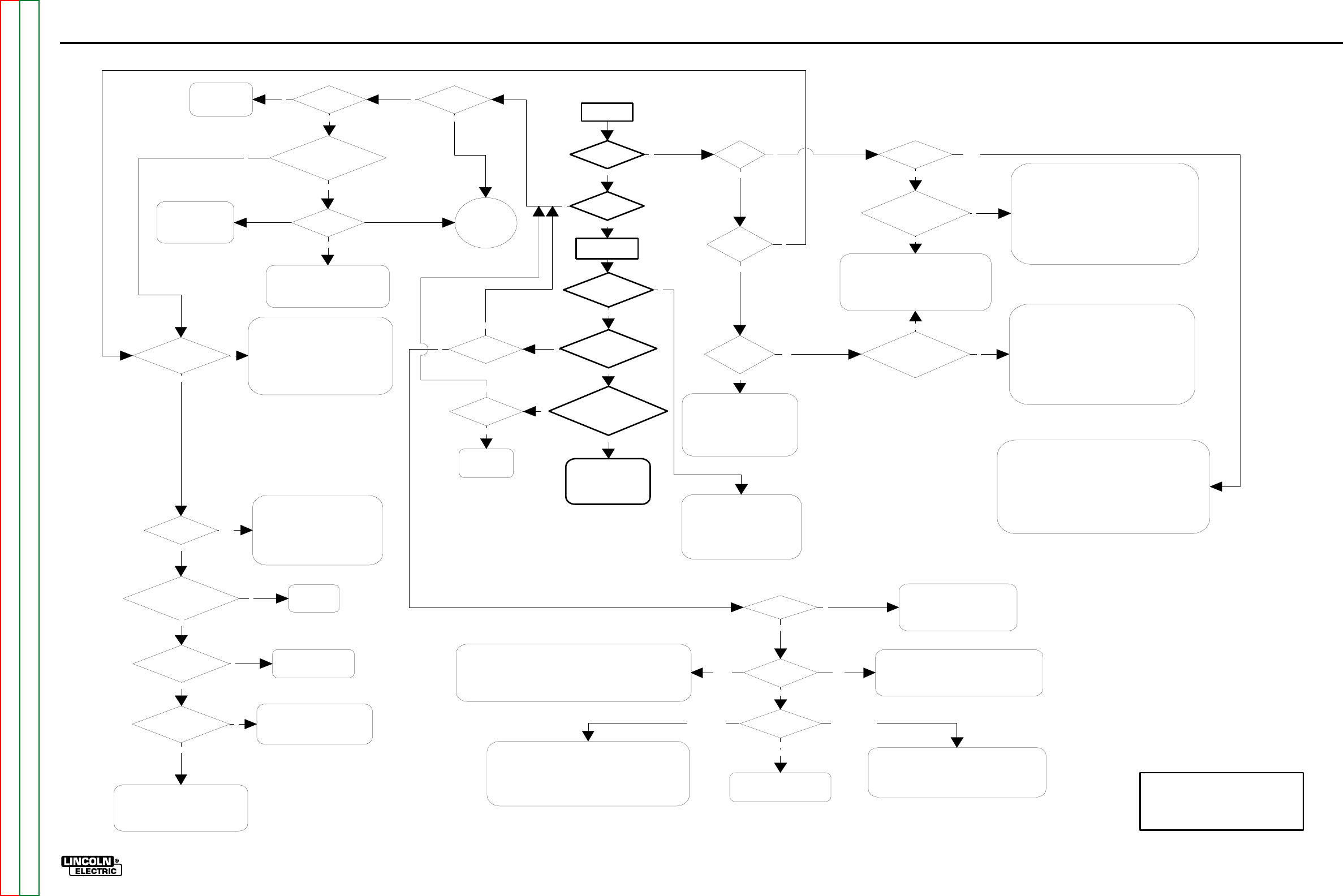
TROUBLESHOOTING AND REPAIR F-95
POWER WAVE 455/POWER FEED 10
FLOWCHART - FUNCTIONAL TROUBLESHOOTING GUIDE
N
UI Status
on?
PS Status
on?
Check For
40VDC at UI
Control Board
Verify 12 VDC is being
supplied to UI Display
PCBD (J1 pin 7 to 8)
Y
OK
At this point, voltage is being supplied to the UI Control
Board, and the on board supply is properly converting it to
12Vdc, which has been verified at the display.
The Status light is not functioning, so the most likely
problem is that the UI Control board is "lost".Try reloading
the UI Software. If problem still exists, Replace the Control
board.
There is a remote possibility that a multiple fault exists in
the harness from the Display to the UI Control board, or in
any combination of the following: The harness, the Display
board
,
and the Status li
g
ht.
Turn On
Main UI Display
panel on?
Errors on UI
Display?
Can you adjust
WFS and Voltage?
Does Wire feed when
you pull the trigger?
Is there OCV from the
brass block to the work stud
with the trigger pulled
Error 100?
Status Light on the PS
on?
Condition of
Status light
Communication Fault.
Check Wiring and
Linc-Net Cables for
open circuit
Go To PS
Error
Interpretation
Guide.
Solid
Red
Error 006?
See UI Error
Chart for
additional error
codes.
Select a CV
Mode
Errors on UI
Display?
Errors on UI
Display?
FH Status On?
Be sure the trigger is engaged long enough to overcome any set preflow
delay, or turn the preflow timer off.
Check trigger circuit operation from the gun to the FH Control Board.
Perform the Drive Motor Test to verify motor voltage is present when the
trigger is pulled.
N
NN
Y
Y
Y
N
Y
Y
N
Condition of
Status Light?
Y
Y
5 Green LED's lit on
the PS Control
Board?
NN
Verify 12 VDC is being
supplied to UI Display
PCBD (J1 pin 7 to 8)
Check connections from UI Control Board to
Display panel. If the display and Status light are
still not functioning, remove P4 from the UI
Control Board.
Check for 12 VDC at J4 pins 1 to 4 , and J4
pins 3 to 8 on the UI Control board. If voltage is
not present, replace UI Control Board
Solid Green
N
N
At this point, voltage is being supplied to the UI Control
Board, and the on board supply is properly converting it to
12Vdc. This has been verified by the condition of the Status
light and by measurement at the display.
Because the Status light indicates a healthy condition, the
problem is most likely in the harness from the Display to
the UI Control board or in the Display board itself. Check the
harness, and run the Display Panel Check.
There is a remote possibility that the Communications
Hardware on the UI Control board is not functioning
properly.
Y
Check PS breaker (CB1), Linc-Net
cables, wiring in UI and PS.
+40 VDC section of Power Board
may be malfunctioning, Perform
Power Board test
Not OK
System is functional. If
performance problems
exist see System
Performance
Troubleshooting guide
Y
Look for open
circuit in the
PS secondary
N
System is stuck in Remapping loop.
Most likely cause is the loss of the
+5Vcan Supply. Check J27 on PS
Control Board, check Power Board,
Etc.
Flashing Green
Y
Verify no Limits are set.
Check Harness for UI Control Board
to the Dislay Panel (specifically the
w
ires to the Encoder Board.
Run The Dual Encoder PC Board
Test
N
Flashing
Red and Green
N
Y
Y
N
Check Status Light and harness
Verify all connections to the PS Control Board
Perform Power Board test to verify correct
voltage levels
Reload the PS Software. If Problem still
exists, replace PS Control Board.
Y
Run Power
Board Test
Check/repair harness between:
The Power Board and the Control Board.
- AND/OR -
The Power Board and the wire feeder
receptacle (S1), including the output
circuit breaker (CB1).
Pass
N
Was 60-80 VDC at Power
Board input connector
Replace the
Power Board.
Fail
Y
Input power does not appear to be
supplied to aux. transformers
Check input power, check reconnect,
check Breakers, check Line Switch, etc.
Voltage at the input to
the Rectifier?
Voltage at the Power
Board Capacitor?
Check/repair harness
between the Power
Board and the Capacitor.
Check for 60 to 80 VDC at the
Output of the rectifier. If present,
check harness from rectifier to
Capacitor. If not replace rectifier
N
N
Y
Y
N
UNHEALTHY STATUS LIGHT WITH BLANK DISPLAY:
Improper system configuration (dipswitch settings) can result in
mapping errors that cause PS to continuously issue a system reset
command. The result is the UI gets stuck in a reset loop, usually
accompanied by a blank display with a green and/or red flashing
status light. Correct the system configuration.
Check the connections on wires 541 & 542, and pins A & B in the
Linc-Net control cable.
UI software may be corrupt. Reload UI soft ware
Other
N
FH Status
Condition?
FH does not appear to have power.
Check +40 VDC connections on
pins "D" & "E" of the Linc Net
receptacle in the FH.
Y
Check the continuity of the Shutdown circuit in the FH (wires
570 & 571). If the path between these wires is interrupted the
FH will not operate and the Status light will flash red while all
other nodes appear normal.
A rapidly flashing red Status light indicates the node needs to be
reprogrammed.
Functional Troubleshooting Guide
Y
(Semi Automatic PW-455, PW455/STT)
Key:
PS = Power Source
UI = User Interface (Control
Box)
FH
=
Feed Head
FH Status
Condition?
Check the system configuration.
If the FH is not recognized as part of a valid group, or if
improper dipswitch settings result in a duplicate or invalid
network assignment, a mapping error will be generated.
The FH has detected no activity from the
communication network.
Check the connections on wires 541 & 542, and pins
A & B in the Linc-Net control cable.
FH has a motor
overcurrent/overtemperature
error.
RedGreen
Flashing
Flashing GreenFlashing Red
Flashing
Red and Green
N
(For Codes 10555 and Below)
F-95
Return to Section TOC Return to Section TOC Return to Section TOC Return to Section TOC
Return to Master TOC Return to Master TOC Return to Master TOC Return to Master TOC

G-1
ELECTRICAL DIAGRAMS
G-1
TABLE OF CONTENTS
-ELECTRICAL DIAGRAMS SECTION-
ELECTRICAL DIAGRAMS . . . . . . . . . . . . . . . . . . . . . . . . . . . . . . . . . . . . . . . . . . . . . . . . . . . . . . . . . . SECTION G
POWER WAVE 455 WIRING DIAGRAM - CODE 10372 . . . . . . . . . . . . . . . . . . . . . . . . . . . . . . . G-2
POWER WAVE 455 WIRING DIAGRAM - CODE 10555 . . . . . . . . . . . . . . . . . . . . . . . . . . . . . . . G-3
POWER WAVE 455 WIRING DIAGRAM - CODE 10553 . . . . . . . . . . . . . . . . . . . . . . . . . . . . . . . G-4
POWER FEED 10 CONTROL BOX WIRING DIAGRAM. . . . . . . . . . . . . . . . . . . . . . . . . . . . . . . . G-5
POWER FEED 10 WIRE DRIVE WIRING DIAGRAM . . . . . . . . . . . . . . . . . . . . . . . . . . . . . . . . . . G-6
POWER FEED 10 MACHINE SCHEMATIC . . . . . . . . . . . . . . . . . . . . . . . . . . . . . . . . . . . . . . . . . G-7
POWER WAVE 455 MACHINE SCHEMATIC - CODE 10372. . . . . . . . . . . . . . . . . . . . . . . . . . . . G-8
POWER WAVE 455 MACHINE SCHEMATIC - CODE 10555. . . . . . . . . . . . . . . . . . . . . . . . . . . . G-9
POWER WAVE 455 MACHINE SCHEMATIC - CODE 10553. . . . . . . . . . . . . . . . . . . . . . . . . . . . G-10
POWER WAVE 455 CONTROL PC BOARD SCHEMATIC (1 of 3) . . . . . . . . . . . . . . . . . . . . . . . G-11
POWER WAVE 455 CONTROL PC BOARD SCHEMATIC (2 of 3) . . . . . . . . . . . . . . . . . . . . . . . G-12
POWER WAVE 455 CONTROL PC BOARD SCHEMATIC (3 of 3) . . . . . . . . . . . . . . . . . . . . . . . G-13
POWER WAVE 455 POWER PC BOARD SCHEMATIC . . . . . . . . . . . . . . . . . . . . . . . . . . . . . . . G-14
POWER WAVE 455 INPUT PC BOARD SCHEMATIC . . . . . . . . . . . . . . . . . . . . . . . . . . . . . . . . . G-15
POWER WAVE 455 SWITCH PC BOARD SCHEMATIC - CODE 10372 & 10555. . . . . . . . . . . . G-16
POWER WAVE 455 SWITCH PC BOARD SCHEMATIC - CODE 10553 . . . . . . . . . . . . . . . . . . . G-17
POWER FEED 10 MOTHER CONTROL PC BOARD SCHEMATIC . . . . . . . . . . . . . . . . . . . . . . G-18
POWER FEED 10 CONTROL PC BOARD SCHEMATIC . . . . . . . . . . . . . . . . . . . . . . . . . . . . . . G-19
POWER FEED 10 DISPLAY PC BOARD SCHEMATIC. . . . . . . . . . . . . . . . . . . . . . . . . . . . . . . . G-20
POWER FEED 10 ENCODER PC BOARD SCHEMATIC. . . . . . . . . . . . . . . . . . . . . . . . . . . . . . . G-21
POWER FEED 10 VOLTAGE SENSE PC BOARD SCHEMATIC. . . . . . . . . . . . . . . . . . . . . . . . . G-22
Return to Master TOC Return to Master TOC Return to Master TOC Return to Master TOC

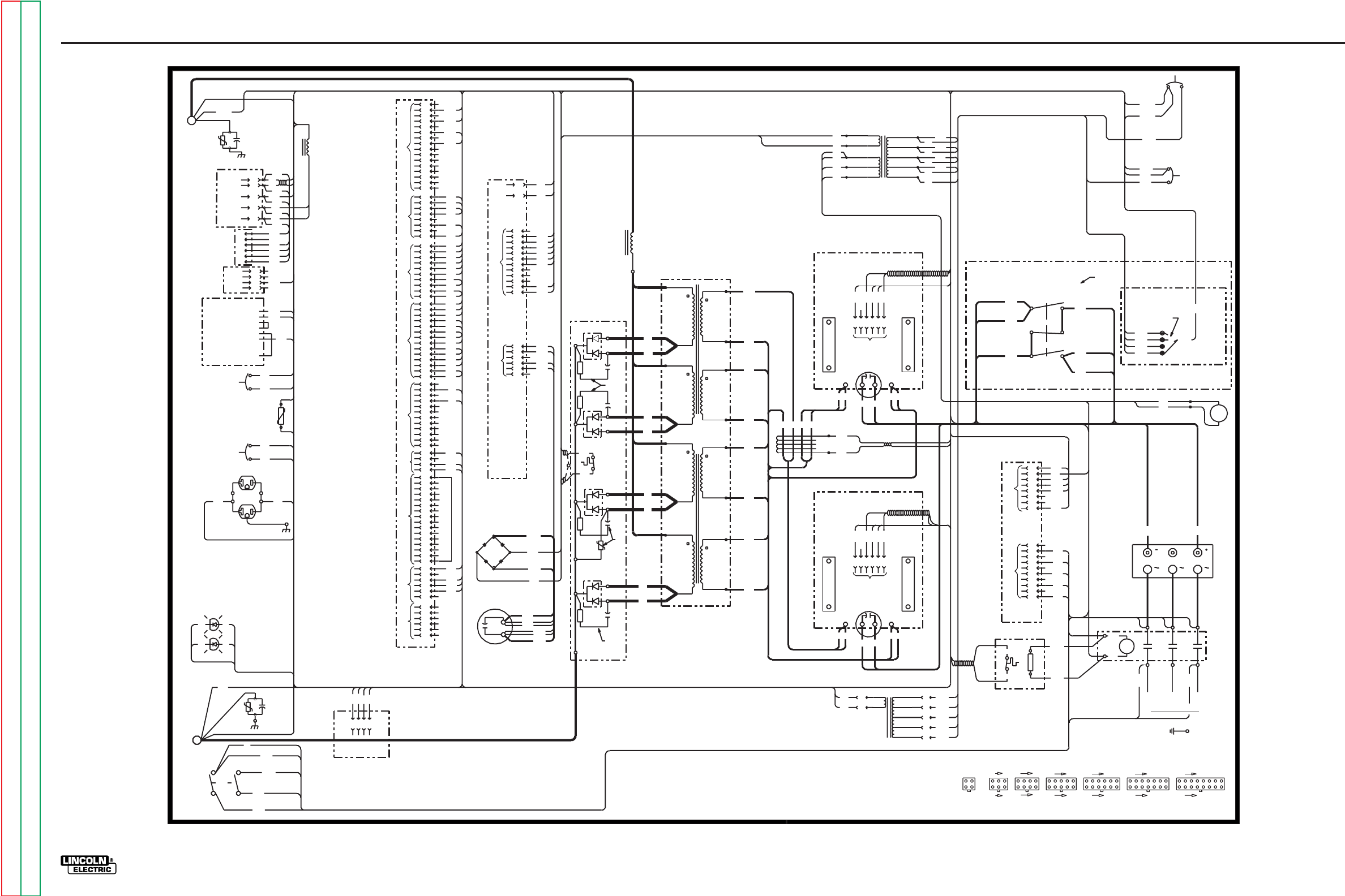
G-2
ELECTRICAL DIAGRAMS
POWER WAVE 455/POWER FEED 10
Power Wave 455 Wiring Diagram - Code 10372
13
TO CONTACTOR
L3A
53
TO
CT
P90
10
3
4
6
406
239
G3051
19C
220
NEG
NEG
NEG
RIGHT)
RIGHT)
RIGHT SIDE
INPUT BOARD
1601
TO CURRENT
TRANSFORMER
+
C5
17
H5
CB3
21
405
604
274
6
1
2
3
4
5
6
J31
52
50
TP3
TO
J81
CB2
33
32
3
4
3
4
5
7
15
J25
TP2
.05/600V
+
213
212
C3
216
(440-460)
TO
S4 (380-415)
CB2
POS
H3
POS
2
(220-230)
H2
TO
(200-208)
H1
C2
211
J20
B
POWER BOARD
A
C
L2
ELECTRODE
WORK
E
TO CB1 S1
POWER BOARD
S1
51BK 51
1
2
3
CB1
4
5
D
J27
TO
J20
67A
54A
54A
51A
67B
16
J21
H1D
TO TP3
612B
TO J61
TO CB3
TO RECONNECT PANEL
TO CONTACTOR
P90
CURRENT
TRANSDUCER
53
RIGHT SIDE OF MACHINE
F1
F1
J25 J50,J81 J21,J60
31
46
4
10W
2.7
3273 S1
J27 X1
J28
2
3
TO J21
1
POS
4
SW1
POWER
S4
S2
CB2
SENSE
BREAKER
CB1
10A CIRCUIT
BREAKER
VOLTAGE
110V RECEPTACLE
P6
10A CIRCUIT
USER
RECEPTACLE
S3
RS232
CONNECTOR
J81
S4
TO
TO
WORK
ELECTRODE
L2
TO
BOARD
POWER
J26
J24
6
5
5
4
+
1B
2B
1
2
3
4
21A
TO
1
2
J20
3
4
5
253
6
7
254
251
TO
J25
9
20
31
TO CURRENT
TRANSFORMER
LEFT)
TO SWITCH
BD #1
11
(TOP
PRIMARY
12
20C
12
(BOTTOM
SECONDARY
2
1
3
LEFT)
(BOTTOM
SECONDARY
LEFT)
TO SWITCH BD #2
PRIMARY
(TOP
LEFT)
TO CURRENT
TRANSFORMER
50
10
9
8
7
6
5
4
3
1
2
TO
OUTPUT RECT
226
7
8
9
10
11
273
1
2
274
228
AUX. #1
TO
N.D.
TP5
J32
BD.
POWER
RECT.
220-230V
N.D.
380-415V
CONNECTION SHOWN IS FOR 440-460V OPERATION.
440-460V
N.C. PLACE "A" LEAD ON APPROPRIATE CONNECTION FOR INPUT VOLTAGE.
FAN
150 5W
R
TO CURRENT
TRANSFORMER
20C
17
RECONNECT PANEL
COMPONENT VALUES:
TO SWITCH
BD #2
TO SWITCH BD #1
NEG
H2
TO AUX #1
PRIMARY
CAPACITORS=MFD/VOLTS
(BOTTOM
RIGHT)
RESISTORS=OHMS/WATTS
TO INPUT RECT
T0
RECT
1
THERM
224A
SECONDARY
N.C.
H1A
TO SW1
TO CB4
TO P80
612A
612
H1
TO AUX #1
H5
H5
(440-460)
AUXILIARY TRANSFORMER #1
H4
RECONNECT PANEL
H4
X1 W
(380-415)
(200-208) H2
H2
(51V)
X2
H3
H1
(220-230)
WJ61
TO CB3
21A
6
7
206
867A
TO
S2
H3
J50
H4
H5
1
2
3
4
5
6
234
T3
L3
W
TO
CR1
J23
8
7
10
CONNECTOR CAVITY NUMBERING SEQUENCE
6
239
235
1
54
NEG
9
TO
254
253
LED
TO
STATUS
2
9
8
7
6
5
1
404
12
506
13
403
14
1W
1B
3
4
10
11
11
1
3
H4A
4
H5A
3
#2
ELECTRICAL SYMBOLS PER E1537
LEAD COLOR CODING
(115V)
TRANSFORMER
AUXILIARY
433
32
TO J23
503
506
H1A
1
2
8
9
10
H3A
8
7
H2A
6
H4
W
R
1
P81
LED
RECT.
THERMAL
THERM.
TO FAN THERM
225
223
222
221 J22
J27
10W
2.7
D4
LEFT SIDE
X5
X4
CR1
X3
J60
TO
H4A
FAN
H3A CB4
TO
5
14
1
(VIEWED FROM COMPONENT SIDE OF BOARD)
4
X3
F4
800V
F4
.022
F3
F3
.022
800V
F2
.022
F2
800V
POS
X2
MAIN CHOKE
L1
S3
TO CURRENT
TRANSFORMER
TO INPUT RECT
POS
19D
19C
TO SWITCH BD #2
TO SWITCH BD #1
RECONNECT SWITCH
10W
.022
800V
D3
2.7
10W
TO
2
3NEG
RECTIFIER
NEG
SW1
INPUT
AUX #1
SWITCH
RECONNECT
TO
TO J61
601
X4
TO AUX #1
FAN THERM
20D
TO SWITCH BD #2
FAN THERM
T3
V
J20,J26
1
TO J60
9
7
L3A
TO SW1
14
1
8
5
AC
50WT
AC
POWER BD RECTIFIER
211
213
214
2W
2B
216
503
202
ALIGNS WITH BLACK LEAD OF LED SOCKET.
CONNECTION SHOWN IS FOR 380-460V OPERATION.
N.A. PIN NEAREST THE FLAT EDGE OF LED LENS (CATHODE)
N.B. PLACE SWITCH IN APPROPRIATE POSITION FOR INPUT VOLTAGE.
NOTES:
52A
INTERFACE
ELECTRODE
FRONT OF MACHINE
J31
223
4
TO
1
6
J40
J50
235
7
J60
8
232
233
234
231
225
3
226
5
214 TO J21
218
2X3
3
J60
238
4
5
604
6
232 J23
20D
TO
H5A
H2A
N
H1
(24V)
(115V)
212
2
1
2
1
15
14
13
12
11
10
9
SWITCH BOARD #2
TO MAIN TRANS
13
TO RECONNECT
+
6
C4
406
5405
J40
4
CURRENT
404
TRANSFORMER
403
SWITCH BOARD #1
233
16
15
14
12
18
16
6
2
1
12
238
AC2
T1
AC3
J61 CR1
612
T2
L1A
CB4
L2
H1D
U
'A'
PRIMARY
X3
TO AUX #1
X5
J22,J61
CR1
J24,J31
61
12
19D
TO RECONNECT SWITCH
(BOTTOM
16
(TOP
15
RIGHT)
(TOP
TO SWITCH
BD #1
13
TO MAIN TRANS
B=BLACK
G=GREEN
N=BROWN
R=RED
U=BLUE
W=WHITE
N.B.
THIS AREA VIEWED FROM REAR OF MACHINE
A
(TOP)
2
L1A
31
1W
THERMAL LED (Y)
2W
STATUS LED (R/G)
TO J24
LINE
LOAD
TO J22
N.A.
TO J20
206
N.A.
16
8
G
U
NATIONAL ELECTRICAL CODE.
TO A SYSTEM GROUND PER
L1
TO SW1
TO SUPPLY LINES
AC1
POS
POS
REAR OF MACHINE
TO AUX #1
BREAKER
10A CIRCUIT
CB3
612A
TO J23
612B
AUX #2
MAIN TRANSFORMER
15
TO CURRENT
TRANSFORMER
3-19-99D
SECONDARY
18
11
-
P6
H3
RECEPTACLE
POWER BD. RECTIFIER
TO
1
4
2
3
CONTROL BOARD
TO
TP3
202
TO J20
WORK
C1
.05/600V
TP1
53A
S1
WIRE
FEEDER
TO
S1
6
2
228
J23
J32
220
5
7
6
5
11
POS
12
POS
NEG
1
2
3
4
3
4
8218
221
67B
222
52
TO
54
J31
J22
52A
51
51A
53A
231
601A
X4A
4
290
RECT
THERMOSTAT
FAN
THERM
TO
J27,J28
J32,J40
7
6
5
T2
T1
224
251
8
10
11
12
13
14
16
4
5
CB1 TO
BREAKER
6A CIRCUIT
CB4
TO
C3
LEFT SIDE OF MACHINE
2.7
J22
TO SW1
N.D. MAY NOT APPEAR ON ALL MACHINES.
200-208V
290
D2
RECT.
224
D1
THERM.
224A
TO
C3
N.D.
G-2
Return to Section TOC Return to Section TOC Return to Section TOC Return to Section TOC
Return to Master TOC Return to Master TOC Return to Master TOC Return to Master TOC
NOTE: This diagram is for reference only. It may not be accurate for all machines covered by this manual. The wiring diagram specific to your code is pasted inside one of the enclosure panels of your machine.
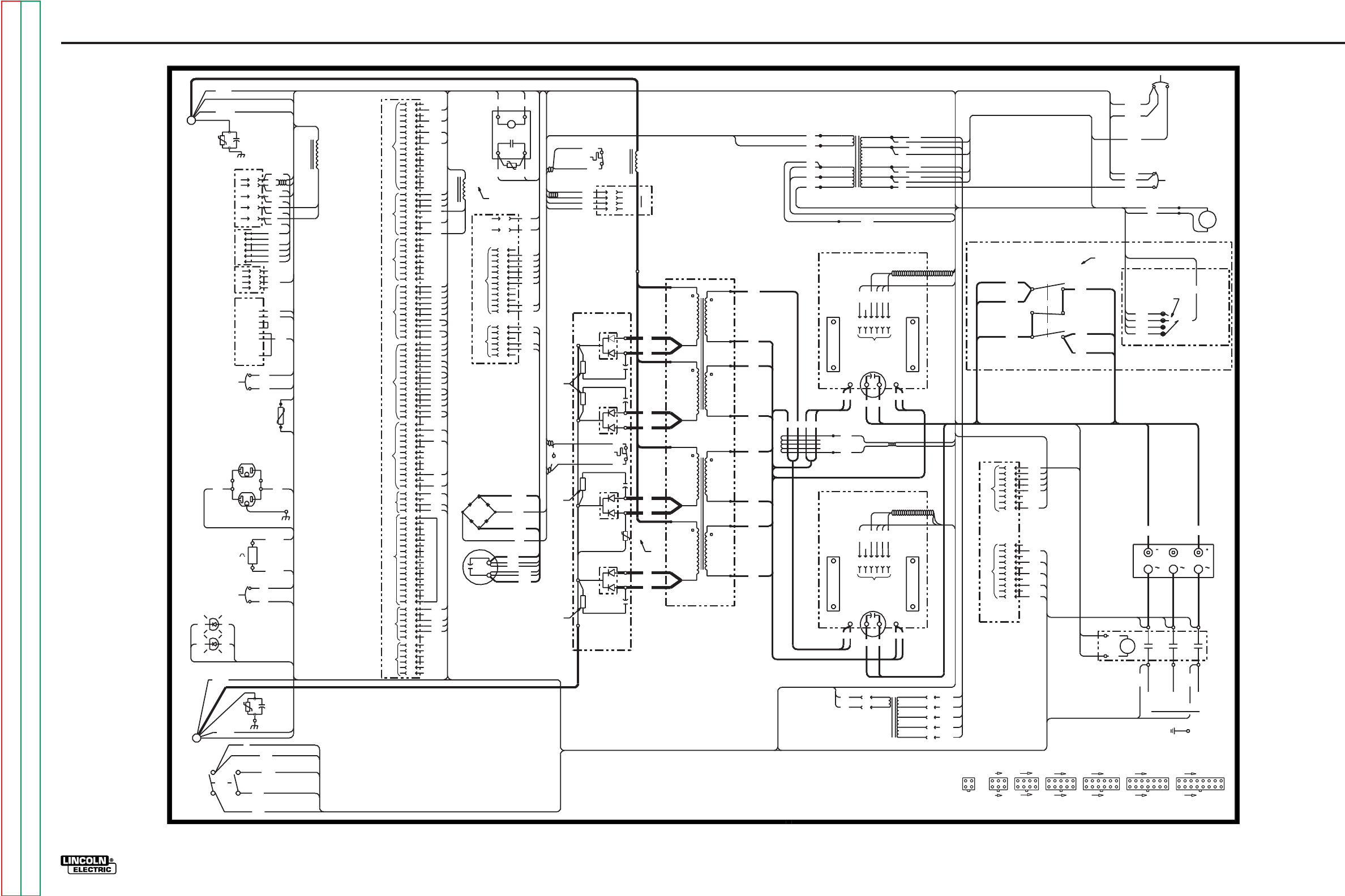
G-3
ELECTRICAL DIAGRAMS
POWER WAVE 455/POWER FEED 10
Power Wave 455 Wiring Diagram - Code 10555
G-3
Return to Section TOC Return to Section TOC Return to Section TOC Return to Section TOC
Return to Master TOC Return to Master TOC Return to Master TOC Return to Master TOC
31
L3A
18
TO AUX #1
TO CURRENT
32
33
4
POS
X2
4
POWER BD RECTIFIER
J24
NEG
TO
J32
NEG
NEG
NEG
POWER BD RECT
C3
+
32
TO
J81
L1A
A
H1D
31
TO J61
612B
S4
TO CB3
(TOP)
2
FRONT OF MACHINE
110V RECEPTACLE
TO TP3
TO CONTACTOR
TO CONTACTOR
TO RECONNECT PANEL
11
TO SWITCH
11
16
BD #1
12
TRANSFORMER
TO CURRENT
BD #2
16
PRIMARY
(TOP
LEFT)
TRANSFORMER
RECT.
TO CURRENT
F4
TO SWITCH
THERM.
C3
D4
TO
OUTPUT RECT
273
274
TO
J27
J22
SECONDARY
(BOTTOM
LEFT)
PRIMARY
(BOTTOM
LEFT)
SECONDARY
(TOP
LEFT)
MAIN TRANSFORMER
LEFT SIDE
N.D.
TO CURRENT
3
ELECTRODE
21A WORK
4
4
MAIN CHOKE
L1
3
TP1
2
H1A
++
P6
TO AUX #2
J20
612B
54A
67A
TO SW1
67B
TO J61
CB3
612A
612
H1
TO AUX #1
TO SOLID STATE RELAY
4
TO CB4
C1
612A
AUXILIARY TRANSFORMER #1
TO
AUX #2
H1A
TO
H5
S4
CB2
6
1
(440-460) H5A
P81
3
(380-415)
H3
H4A
H2
2
(220-230) H3A
H2A
H1
(200-208) 4
AUXILIARY TRANSFORMER #2
5
4
6
SWITCH BOARD #1
J21A,J21B
TO SW1
RECONNECT PANEL
CB3
10A CIRCUIT
BREAKER
1
'A'
J32,J40
J50,J81
403
406
TO J23
D2
10W
2.7
AUX. #1
1
THERM
CHOKE
TO
10W
2.7
10W
2.7
TO J22
CB2
L2
N.D.
C3
TO
224
224A
AC
52A
1
4
3
2
TRANSFORMER
218
TO CURRENT
TRANSFORMER
D1
800V
.022
POS
POS
2.7
10W
N.D.
TRANSFORMER
15
.022
800V
POS
RECTIFIER
INPUT
U
SWITCH
TO
RECONNECT
L1A
T2
TO SW1
503
234
4
5
7
L3A
8
TO A SYSTEM GROUND PER
NATIONAL ELECTRICAL CODE.
4
TO SUPPLY LINES
G
AC1
POS
AC2
J22
3
4
254
253
7
6
5
4
3
2
1
6
D
C
B
A
2
1
8
7
6
5
(220-230) H3A
H2
H1
H2
H3
(200-208)
N
H1
(24V)
R
(115V)
(51V)
6
5
H4
W
R
+
19D
J50
(115V)
403
503
506
404
235
604
405
1B
239
238
406
1W
TO MAIN TRANS
1
1
2B
214
213
212
N.D.
212
50
NEG
CB1
3
2
221
1
9
8
6
5
POWER BD
TO
TO AUX #1
2T1
3
T2 TO
J61 CR1
6612 SW1
CB4
H1D
9
T3
T1
L2
WORK
ELECTRODE
206A
J27
TO
S4
31
J81
CR1
X4
S3
RS232
CONNECTOR
REAR OF MACHINE
ELECTRODE
4
LOAD
LINE
SW1
POWER
G3051-1
S1
WIRE
FEEDER
RECEPTACLE
FAN
CB4
6A CIRCUIT
BREAKER
S2
VOLTAGE
SENSE
RECEPTACLE
3-19-99D
202A
TO TP3
TRANSFORMER
+
NEG
NEG
AC3
T3
L3
TO SW1
WV
CB4
S2
H4A
RECONNECT PANEL
202
2
2
3
14
8
TO
251
11
S3
12
253
1
254
2
3
J40
+
C4
13 14
POWER BOARD
H5A
H5
(440-460)
H4
U
(380-415)
TO J20
-
202
+
X5
TO RECT THERM
224A
CHOKE
-
WORK
LEFT SIDE OF MACHINE
CONTROL BOARD
N.C.
X5
H5
H4
444
H3
H2
RECONNECT SWITCH
TO SWITCH BD #2
THIS AREA VIEWED FROM REAR OF MACHINE
TO L7
206A
405
404
1
TO CURRENT
X3A
TO SOLID STATE RELAY
TO AUX#1
P6
USER
INTERFACE
220
14
15
CURRENT
800V
.022
800V
.022
P91
CURRENT
TRANSDUCER
TO J24
TO J22
50
CB1
10A CIRCUIT
BREAKER
TP2
TO
WORK
1W
2W
C2
ELECTRODE
N.A.
206
N.A.
THERMAL LED (Y)
TO J20
STATUS LED (R/G)
52
1B
.05/600V
2B
TO R1
8
7
6
5
4
1
3
8
7
6
5
4
3
2
16
15
14
J21B
J21A
506
239
TO SWITCH
TO J23
11
21
3
7
TRANSFORMER
TO R1
291
THERM.
TO J21A 216
211
213
TO SWITCH BD #1
20C
TO INPUT RECT
19C
POS
TO SWITCH BD #1
N.B.
NEG
TO INPUT RECT
TO SWITCH BD #2
20D
19D
14
J20,J26
7
9
8
1
12 16
7
10
L1
J23
8
CONNECTOR CAVITY NUMBERING SEQUENCE
(VIEWED FROM COMPONENT SIDE OF BOARD)
11
6
J22,J61
561
J24,J31
228
L2
TO
225
50
2
2
S1
TO
67B
51A
54A
52
13
CURRENT
12
J27
TO
11
TO
10
67A
9
8
POWER BD
J20
CB1
L2
TO
.05/600V
TO MAIN TRANS
TRANSFORMER
8
7
J60
6
231
5
4
3
232
2
604
238
X3
601
3
INPUT BOARD
4
17 18
1
2
10
5
21A
53A
2
51A
51
3
52A
4
1
53A
54
E
53
TO AUX#1
J31
S1
TO
51
X1
53
X3A
TO
SOLID STATE RELAY
274
TP4
J32
273
STATUS LED
AC
POS
NEG
POS
POS
6
5
4
J60
J50
J40
TO
231
THERM.
TP3
220
2W
12
11
10
9
J26
9
10
7
6
5
1
3
2
11
13
12
10
13
4
43
54
12
1
4
2
AUX #1
J25
380-415V
3R
3W
CAPACITORS=MFD/VOLTS
RESISTORS=OHMS/WATTS
TO
1
CB3
6
440-460V
220-230V
200-208V
6
5
4
3
2
1
16
15
14
1211
1
216
218
444
50WT
221
222
223
224
225
226
TO
J31
1
LED
J31
THERMAL
5
6
7
8
9
10
11
12
RECT.
4
P91
TO
N.D.
L7
235
F2
F2
SECONDARY
(BOTTOM
RIGHT)
BD #1
PRIMARY
(TOP
RIGHT)
13
SECONDARY
(TOP
RIGHT)
RIGHT SIDE
15 16
PRIMARY
(BOTTOM
RIGHT)
C5
17
BD #2
TO SWITCH
F1
F1
SWITCH BOARD #2
20D
TO RECONNECT SWITCH
TO
CR1
J23
AUX #1
222
223
3
214
2
51BK
TO FAN
233
X1 WH5
CONNECTION SHOWN IS FOR 440-460V OPERATION. 8
J60
1
3
5
COMPONENT VALUES:
ELECTRICAL SYMBOLS PER E1537
LEAD COLOR CODING
B=BLACK
G=GREEN
NOTES:
N.A. PIN NEAREST THE FLAT EDGE OF LED LENS (CATHODE)
ALIGNS WITH BLACK LEAD OF LED SOCKET.
N.B. PLACE SWITCH IN APPROPRIATE POSITION FOR INPUT VOLTAGE.
N=BROWN
U=BLUE
R=RED
W=WHITE
RIGHT SIDE OF MACHINE
J27,J28
N.D MAY NOT APPEAR ON ALL MACHINES.
N.C. PLACE "A" LEAD ON APPROPRIATE CONNECTION FOR INPUT VOLTAGE.
CONNECTION SHOWN IS FOR 380-460V OPERATION.
J25
4
3
J28
8
7
6
5
3
2
1
4
5
6
202A
226
TO RECONNECT SWITCH
12
20C 19C
228
10
9
33
J25
20
TO
251
TO J61
J20
TO J60
TO
601
291
D3
R1
TP7
1
CB2
10A CIRCUIT
BREAKER
7
234
233
232
J23
4
3
2F4
TO
F3
F3
TO FAN
H3
H4
W
H2A
X4
X3
X3
X2
J60
CR1
TO
TO POWER BD. RECTIFIER
3W
SOLID
STATE
RELAY
J24
TO
3R
206
6
5
S1
TO
1
NOTE: This diagram is for reference only. It may not be accurate for all machines covered by this manual. The wiring diagram specific to your code is pasted inside one of the enclosure panels of your machine.
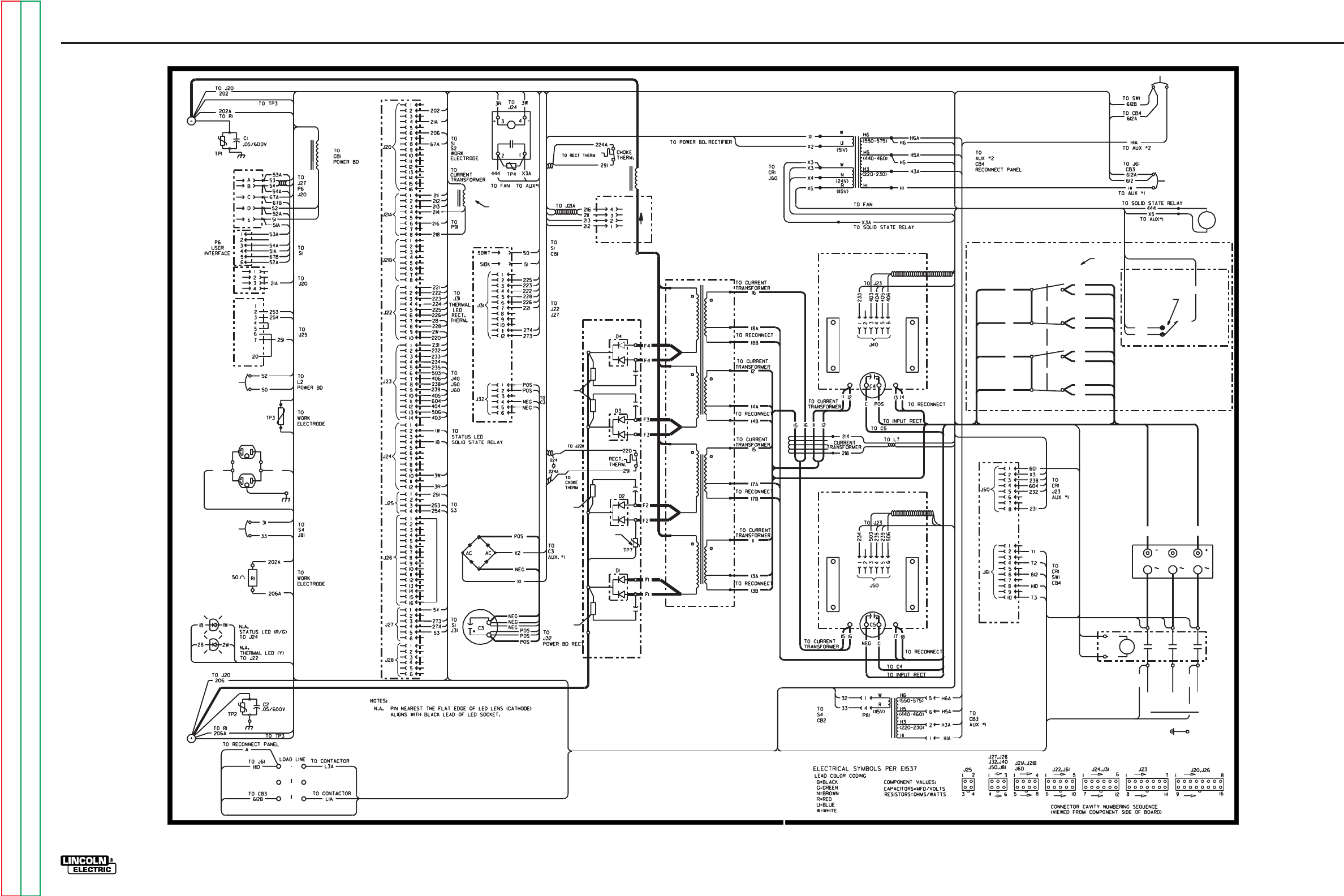
G-4
ELECTRICAL DIAGRAMS
POWER WAVE 455/POWER FEED 10
Power Wave 455 Wiring Diagram - Code 10553
G-4
Return to Section TOC Return to Section TOC Return to Section TOC Return to Section TOC
Return to Master TOC Return to Master TOC Return to Master TOC Return to Master TOC
LEFT SIDE OF MACHINE
CB4
6A CIRCUIT
BREAKER
S1
WIRE
FEEDER
RECEPTACLE
++
P91
CURRENT
TRANSDUCER
13 14B
CR1
T3
TO AUX #1
T2
TO SW1
L3
L3A
T1
W
L2
TO SWITCH BD #1
TO TOP RIGHT PRI
13B
THIS AREA VIEWED FROM REAR OF MACHINE
L1
TO SW1
L1A
TO BOTTOM RIGHT PRI
18A
TO SWITCH BD #2
17
TO TOP LEFT PRI
TO BOTTOM RIGHT PRI
TO AUX #1
TO SWITCH BD #1
14
TO TOP LEFT PRI
H5
TO TOP RIGHT PRI
13A
H6
14A
TO BOTTOM LEFT PRI
L2
SECONDARY
(TOP
RIGHT)
PRIMARY
(TOP
RIGHT)
WORK
FRONT OF MACHINE
S4
CB1
10A CIRCUIT
BREAKER
31
110V RECEPTACLE
17A
N.B.
RECONNECT SWITCH
INPUT BOARD
POWER BOARD
N.D. MAY NOT APPEAR ON ALL MACHINES.
18
V
TO A SYSTEM GROUND PER
U
TO SUPPLY LINES
G
POS
TO SW1
RECONNECT PANEL
L7
N.D.
800V
.022
10W
2.7
18B
17B
N.C.
TO SWITCH
BD #2
AUXILIARY TRANSFORMER #2
AUXILIARY TRANSFORMER #1
CONTROL BOARD
CB2
10A CIRCUIT
BREAKER
SWITCH BOARD #2
VOLTAGE. CONNECTION SHOWN IS FOR 550-575V OPERATION.
N.D.
800V
.022
N.D.
10W
2.7
G3051-2
CB3
10A CIRCUIT
BREAKER
ELECTRODE
NATIONAL ELECTRICAL CODE.
SW1
POWER
TO SWITCH BD #2
'A'
440-460V
550-575V
RECTIFIER
REAR OF MACHINE
TO SWITCH
BD #1
POS
AC1
RIGHT SIDE OF MACHINE
800V
.022
2.7
10W
N.D.
SECONDARY
(BOTTOM
RIGHT)
RIGHT SIDE
POWER BD RECTIFIER
VOLTAGE. CONNECTION SHOWN IS FOR 550-575V OPERATION.
N.B. PLACE SWITCH IN APPROPRIATE POSITION FOR INPUT
N.C. PLACE "A" LEAD ON APPROPRIATE CONNECTION FOR INPUT
SECONDARY
(TOP
LEFT)
MAIN TRANSFORMER
LEFT SIDE
PRIMARY
(TOP
LEFT)
AC3
TO J61
601
AC2
X4
SECONDARY
(BOTTOM
LEFT)
PRIMARY
(BOTTOM
RIGHT)
PRIMARY
(BOTTOM
LEFT)
N.D.
32
NEG
INPUT
TO
J81
TO J60
CB2
SWITCH BOARD #1
800V
2.7
10W
NEG
MAIN CHOKE
L1
SOLID
STATE
RELAY
(TOP)
FAN
S2
VOLTAGE
SENSE
RECEPTACLE
S3
RS232
CONNECTOR
TO BOTTOM LEFT PRI
3-19-99D
.022
OUTPUT RECT
NOTE: This diagram is for reference only. It may not be accurate for all machines covered by this manual. The wiring diagram specific to your code is pasted inside one of the enclosure panels of your machine.
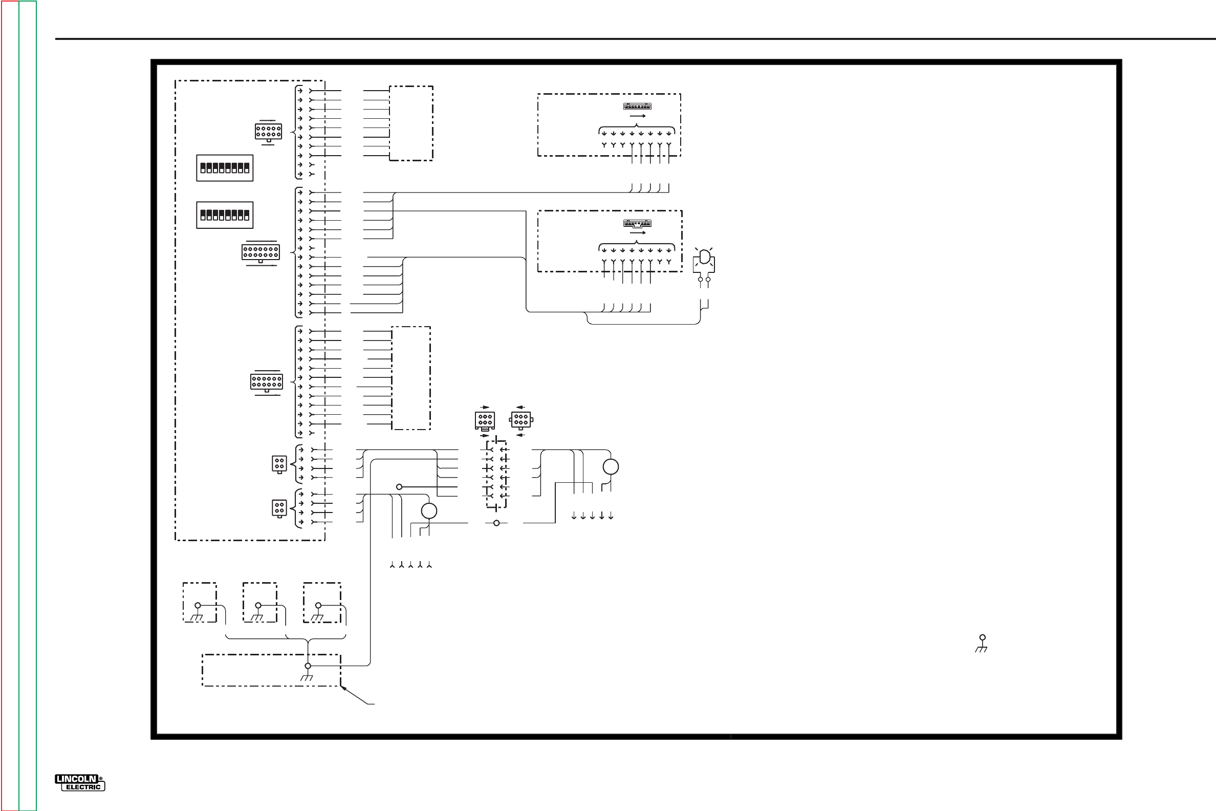
G-5
ELECTRICAL DIAGRAMS
POWER WAVE 455/POWER FEED 10
Power Feed 10 Control Box Wiring Diagram
500D
LINC-NET
D
C
540
B
A
TOROID
R.F.
(OPTIONAL FOR
E
BOOM SET UP)
500
E
(P7)
RECEPTACLE
TOROID
N.B.
N.D.
500
2
3
4
540
(J6)
INPUT
542
541
R.F.
(J8)
P.C. BOARD
ENCODER
DUAL
LOWER
OPTION
N.E.
1
21
4
3
4
3
24 33 42
1
540A
500A
542A
541A
12
6
500D
542D
541D
21
512C
2
500C
555
1
556
553
3
2
554
4
1
1
5 6
3
(J1)
N.F.
(J1)
N.F.
(J7 ON WIRE DRIVE OR ON INPUT RECEPTACLE SHOWN)
511
560
561
559
562
563
500D
557
500E
558
512A
555
556
553
554
540D
500C
551
512
512C
A
B
87
540D
C
6
D
54
OUTPUT
LINC-NET
3
N.A.
(J2)
N.A.
(J1)
11
3
3
4
6
6
4
N.B.
67
67
541D
542
TOP
(J3)
541
BOTTOM
N.C.
N.A.
STATUS LED
N.A.
(J4)
(J5)
RED/GREEN
N.A.
542D
PANEL PANEL
MIDDLE PANEL
CONTROL BOX
400D 400C 400B
5
512B
6
565
7
564
8
9
500F
10
566
UPPER
567
568
OPTION
N.E.
569
USER
DISPLAY
P.C. BOARD
OFF
550
552
551
2
MOTHER
1
INTERFACE
9
8
7
6
5
4
3
2
1
10
11
12
13
14
8
7
6
5
4
3
1
2
9
10
11
12
LEAD COLOR CODING
W - WHITE
N.C. PIN NEAREST THE FLAT EDGE OF LED LENS (CATHODE) ALIGNS WITH BLACK
LEAD OF LED SOCKET.
L10586
500
87
W
B
NOTES:
N.A. CAVITY NUMBERING SEQUENCE AS VIEWED FROM COMPONENT SIDE OF PC BOARD.
N.F. CAVITY NUMBERING SEQUENCE AS VIEWED FROM EDGE OF PC BOARD, COMPONENT
N.E. THE OPTION INSTALLED MAY NOT HAVE ALL OF THE SHOWN WIRES. SEE THE
N.G. MAY NOT BE PRESENT ON CODE 10494 OR PRIOR MACHINES.
N.B. CAVITY NUMBERING SEQUENCE AS VIEWED FROM LEAD SIDE OF CONNECTOR.
ELECTRICAL SYMBOLS PER E1537.
B - BLACK
OPTION'S WIRING DIAGRAM FOR ADDITIONAL INFORMATION.
SIDE DOWN.
N.D. TO FEEDER HEAD OR OPTIONAL INPUT LINC-NET RECEPTACLE.
7
8
= CHASSIS CONNECTION
9-11-98D
1
8
1
7
7
OFF 500
14
552
550
B
W
10
6
S1
87654321
ON
4
5
1
BOARD
3
(USED FOR
BENCH SET
UP)
1
18
54 6
512
8
S2
21
ON
5
6
542A
500A
540A
RECEPTACLE
(OPTIONAL)
67
67
67
541A
400A
N.G.
G-5
Return to Section TOC Return to Section TOC Return to Section TOC Return to Section TOC
Return to Master TOC Return to Master TOC Return to Master TOC Return to Master TOC
NOTE: This diagram is for reference only. It may not be accurate for all machines covered by this manual. The wiring diagram specific to your code is pasted inside one of the enclosure panels of your machine.
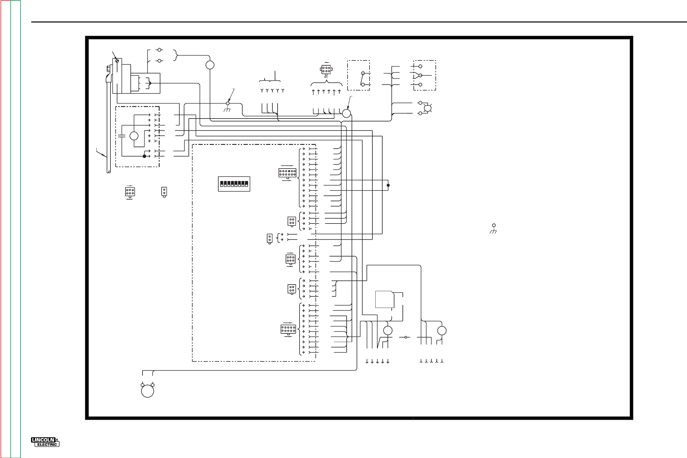
G-6
ELECTRICAL DIAGRAMS
POWER WAVE 455/POWER FEED 10
G-6
Return to Section TOC Return to Section TOC Return to Section TOC Return to Section TOC
Return to Master TOC Return to Master TOC Return to Master TOC Return to Master TOC
Power Feed 10 Wire Drive Wiring Diagram
554
555
557
556
512
559
(J8)
RBEDCA
6
TRIGGER
GAS PURGE
(J7) 1
3
4 STEP
DUAL
2 STEP/
2 6
541D
540D
3 6
542D
542
3
1552
(J3)
511
1
BRIDGE
R
542A
INTERFACE
67A
PROCEDURE
542A
67
571
12
P.M.
U
TACH
65
345
IF USED
4
554
555
CONTROL
P.C. BOARD
21
R.F.
TOROID
551
(J2)
7 86
N.C. PIN NEAREST THE FLAT EDGE OF LED LENS (CATHODE) ALIGNS WITH BLACK
LEAD COLOR CODING
U
N.A. B
4
3
512B W - WHITE
550
553
TOROID
(J9)
1
10
16
S1
53 421
ON
B
OFF
2
1234
540B
2 7
N.B. CAVITY NUMBERING SEQUENCE AS VIEWED FROM LEAD SIDE OF CONNECTOR.
541A
N.D. TOGGLE SWITCHES SHOWN FROM CONNECTION SIDE OF SWITCH.
L10587
ELECTRICAL SYMBOLS PER E1537.
557
(J4)
5
6
1
2
1
N.E.
67
GAS
SOLENOID
543
4
1
32
1
1211
C
A
B
E
D
500
N.A.
542
540C
500D
542D
541
2
7 86 10
9
558
2
570
7
SELECT P.C. BOARD
VOLTAGE SENSE
RECTIFIER
N.A.
R.F.
6
AC
512B
5
432
1
553
552
540C
AC
+
(J1)
N.A.
(J2)
556
559
VOLTAGE SENSING
CONNECTION W551
B
TO USER
550
GUN
TOROID
MOTOR/GEARBOX
INPUT ELECTRODE CABLE
13
N.B.
46
(J1)
67
67
1
2
(J2)
12
3 4 19
541D
COLD INCH/
RECEPTACLE
R.F.
4 8
4
4
3
15
610
540A
541A
541
540B
540
STATUS LED
B
N.C.
R.F.
540A
TOROID
500A
LEAD OF LED SOCKET.
512
(J5)
400
N.A.
= CHASSIS CONNECTION
N.A.
(J6)
N.E. MAY NOT BE PRESENT ON CODES 10494 AND PRIOR MACHINES.
DOWN
SHUT
N.A. CAVITY NUMBERING SEQUENCE AS VIEWED FROM COMPONENT SIDE OF PC BOARD.
67
500D
540D
67
E
D
LINC-NET
500
540
OUTPUT
(J6)
67
RECEPTACLE
500A
(OPTIONAL)
C
B
A
LINC-NET
INPUT
RECEPTACLE
N.D.
512A
558
560
512A
N.D.
RED/GREEN
W
400A
B
(J1)
67A
511
2
N.E.
U - BLUE
R - RED
B - BLACK
W
1
560
-
9-11-98D
NOTE: This diagram is for reference only. It may not be accurate for all machines covered by this manual. The wiring diagram specific to your code is pasted inside one of the enclosure panels of your machine.
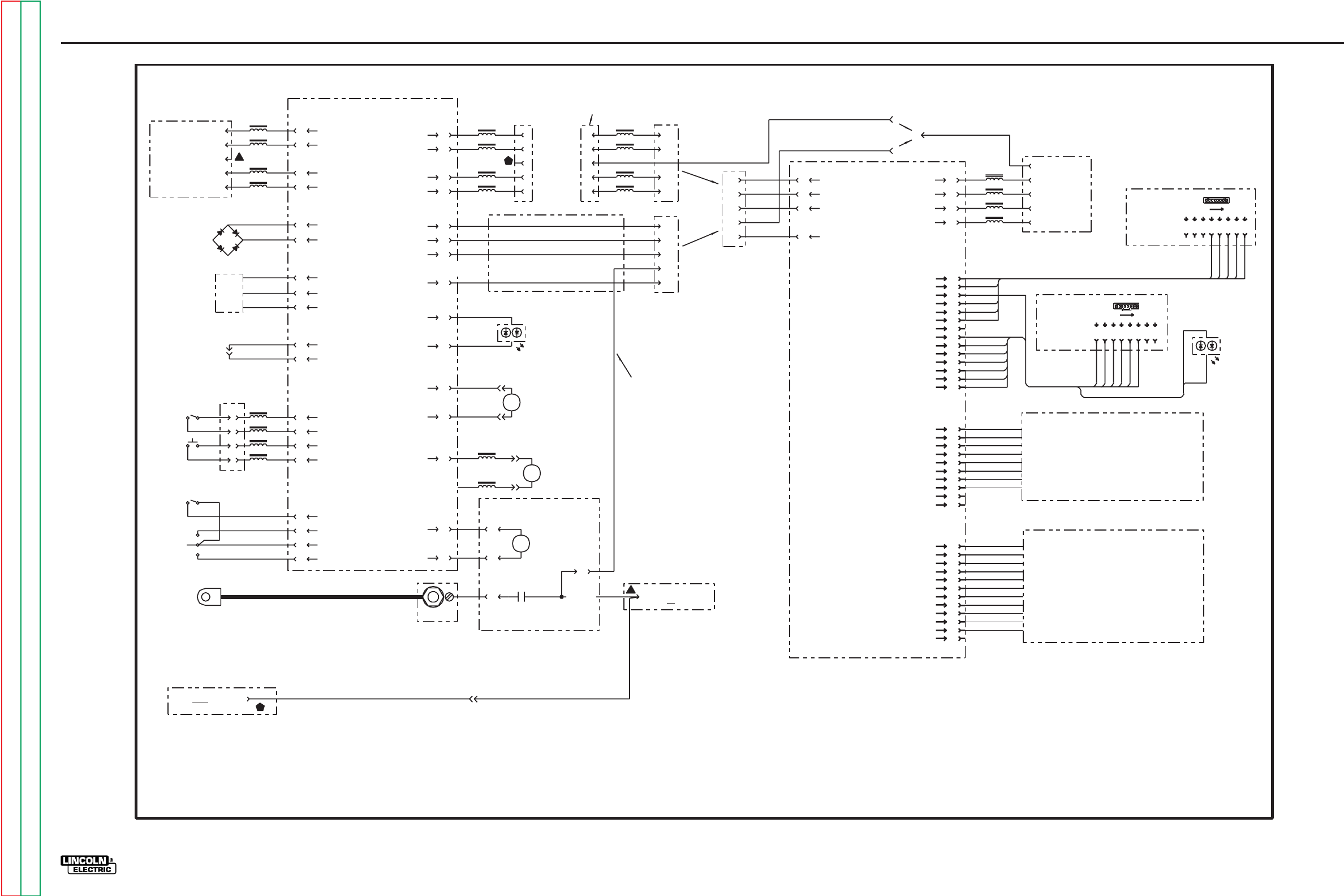
G-7
ELECTRICAL DIAGRAMS
POWER WAVE 455/POWER FEED 10
G-7
Return to Section TOC Return to Section TOC Return to Section TOC Return to Section TOC
Return to Master TOC Return to Master TOC Return to Master TOC Return to Master TOC
POWER FEED 10 MACHINE SCHEMATIC
5J1
3J1
3J1
L2
L2
L1
L1
541
542
540
500
9J1
7J1
541
542
540
500
10J1
6J1
540B
540C
+40 VDC
0 VDC
+40 VDC
BLOCKING
RECTIFIER
+40 VDC
0 VDC
2J4
1J4
+12 VDC
3J4
MOTOR
TACH
R
U
B0 VDC
7J5
9J5
SIGNAL COMMON
SHUT
DOWN
570
571
A
E
D
C
1J5
2J5
L6
L5
L4
12J5
11J5
555
554
556
557
L3
(P11) (J11)
DUAL
PROCESS
TRIGGER
SIGNAL COMMON
SIGNAL COMMON
5J5
4J5
3J5
560
559
512
558
COLD INCH
/
PURGE
512A
2/4 STEP
+12 VDC
PURGE SIGNAL
COLD INCH SIGNAL
512A
6J5
2J2
1J2
L9
L8
L7
3J2
4J2
541D
542D
540D
500D
+40 VDC
0 VDC
J9 OPTIONAL
OUTPUT
RECEPTACLE
L10
541D
542D
540D
500D
4J1
2J1
1J1
8J1
541A
542A
540A
500A
+40 VDC
0 VDC
1J7
3J7
4J7
6J7
10J5
8J5
W
B
RED/GREEN
STATUS
LED
1J2
2J2
6J3
3J3
DUAL PROCESS,
OPEN = PROCESS A
GUN TRIGGER,
CLOSE = FEED HOT WIRE
+40 VDC 552
553
GAS
SOLENOID
TRIGGER ACTION SELECT,
OPEN = 2 STEP
PWM
CONTROL
4J3
1J3
550
551
MOTOR
L12
L11
550
2J6
1J6
+12 VDC 512B
511
1J1
4J1
CR1
CR1
ELECTRODE CABLE
VOLTAGE SENSE
SELECT PCB
(SOLID STATE)
A
B
D
E
C
C
J9 OPTIONAL
OUTPUT
RECEPTACLE
C
551
A
B
D
E
C
5J7
J6 INPUT
RECEPTACLE
TACH SIGNAL INPUT
GUN
RECEPTACLE
GUN
CONTROLS
WIRE DRIVE CONTROL PCB
FEEDER
CONTROLS
WIRE COLOR CODE
B = BLACK
U = BLUE
R = RED
W = WHITE
CATHODE
COMMUNICATION -
COMMUNICATION +
COMMUNICATION -
COMMUNICATION +
COMMUNICATION -
COMMUNICATION +
COMMUNICATION -
COMMUNICATION +
J6 INPUT
RECEPTACLE
67 67
ELECTRODE
VOLTAGE SENSE
CONTROL SIGNAL
OPEN = FAULT
VOLTAGE SENSE
SELECT SIGNAL
WIRE DRIVE
ASSEMBLY
ELECTRODE VOLTAGE
SENSE TO WELDER
ELECTRODE VOLTAGE
SENSE FROM
ADDITIONAL WIRE DRIVE
WIRE DRIVE PCB
CIRCUIT SUPPLY
STATUS LED
(HIGH FOR GREEN)
STATUS LED
(HIGH FOR RED)
2J2
1J2
4J2
3J2
541A
542A
540A
500A +40 VDC
0 VDC
1P7
3P7
4P7
6P7
5P7
COMMUNICATION -
COMMUNICATION +
L2
L2
L1
L1
541
542
540
500
541
542
540
500
A
B
D
E
C67
2J1
1J1
L9
L8
L7
3J1
4J1
541D
542D
540D
500D
+40 VDC
0 VDC
+40 VDC
0 VDC
J6 OPTIONAL
OUTPUT
RECEPTACLE
L10
541D
542D
540D
500D
A
B
D
E
C
COMMUNICATION -
COMMUNICATION +
COMMUNICATION -
COMMUNICATION +
67 ELECTRODE
VOLTAGE SENSE
OR
1J7
3J7
4J7
6J7
67
18
DISPLAY
P.C. BOARD
512
551
500
552
550
500C
554
553
555
556
512
551
500
552
550
500C
512C
553
554
555
556
DUAL
ENCODER
P.C. BOARD
18
B
W
512C
1J4
2J4
3J4
4J4
5J4
6J4
7J4
8J4
9J4
10J4
11J4
12J4
13J4
14J4
1J1
2J1
3J1
4J1
5J1
6J1
7J1
8J1
1J1
2J1
3J1
4J1
5J1
6J1
7J1
8J1
W
B
RED/GREEN
STATUS
LED
CATHODE
512B
565
500F
566
567
568
569
564
1J5
2J5
3J5
4J5
5J5
6J5
7J5
8J5
9J5
10J5
512A
558
500D
559
560
561
562
563
500E
557
1J3
2J3
3J3
4J3
5J3
6J3
7J3
8J3
9J3
10J3
11J3
12J3
511
LOWER OPTION PANELS.
SOME OPTIONS DO NOT HAVE ALL WIRES SHOWN.
UPPER OPTION PANELS.
SOME OPTIONS DO NOT HAVE ALL WIRES SHOWN.
OR
(BOOM)
(BENCH)
67
67
67
ELECTRODE VOLTAGE SENSE
FROM ADDITIONAL WIRE DRIVE
THRU CONTROL BOX WHEN
CONFIGURED AS A BENCH FEEDER
WITH J9 OPTIONAL OUTPUT
RECEPTACLE.
-
-
-
-
+12 VDC -
+12 VDC -
0 VDC -
0 VDC -
ENCODER 1, SIG. B -
ENCODER 1, SIG. A -
ENCODER 2, SIG. B -
ENCODER 2, SIG. A -
STATUS LED (HIGH FOR GREEN) -
STATUS LED (HIGH FOR RED) -
+12 VDC -
0 VDC -
PROC. A -
PROC. B -
+12 VDC -
0 VDC -
POT SUPPLY -
POT WIPER -
MODE 1 -
MODE 3 -
POT COMMON -
* MOSI -
* SCK -
* LATCH -
* MOSI -
* MISO -
* SCK -
* LATCH -
* MOSI -
* MISO -
* SCK -
* LATCH -
* SERIAL
PERIPHERAL
INTERFACE
DUAL PROCEDURE PANEL KIT
DUAL PROCEDURE / MENORY PANEL KIT
CV/GOUGE PANEL (STD)
"M" PANEL KIT
"MSTT" PANEL KIT
"MX2" PANEL KIT
"MSP2" PANEL KIT
J8 OPTIONAL
INPUT RECEPTACLE.
IF CONFIGURED AS BOOM, CONNECTS VIA
ARCLINK CABLE FROM WIRE DRIVE (J9)
OR POWER WAVE 455.
NOTES:
OPTIONAL OUTPUT RECEPTACLE IS REFERENCED (J9) ON WIRE DRIVE AND
(J8) ON USER INTERFACE CONTROL BOX.
541A
542A
540A
500A
CONTROL BOX
USER INTERFACE PCB
INTERNAL HARNESS AND
CONNECTOR USED ONLY IF UNIT
CONFIGURED AS A BENCH FEEDER.
+ PWM
CONTROL
- PWM
CONTROL
W
B
67
67A
67
67
67
67
8-14-98F
G3602
NOTE: This diagram is for reference only. It may not be accurate for all machines covered by this manual.
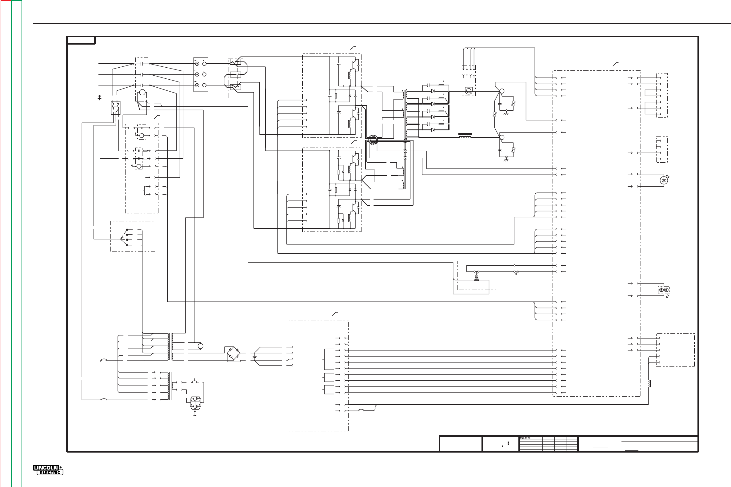
G-8
ELECTRICAL DIAGRAMS
POWER WAVE 455/POWER FEED 10
POWER WAVE 455 MACHINE SCHEMATIC - CODE 10372
U
CR1
NEG
NEG
POS
AC2
L2
L1
W
V
L3 T3
T2
T1
AC1
AC3
380-460V 208-230V
NONE
XA
11-14-97A
3-19-99D
t
UNLESS OTHERWISE SPECIFIED TOLERANCE
ON HOLE SIZES PER E2056
ON 2 PLACE DECIMALS IS .02
WITH PUBLISHED STANDARDS.
ON 3 PLACE DECIMALS IS .002
ON ALL ANGLES IS .5 OF A DEGREE
MATERIAL TOLERANCE (" ") TO AGREE
THE LINCOLN ELECTRIC CO.
CLEVELAND, OHIO U.S.A.
EQUIP.
TYPE
SCALE
DR DATE CHK REF.
SUBJECT
SUP'S'D'G
SHT.
NO.
THE LINCOLN ELECTRIC CO.
THIS SHEET CONTAINS PROPRIETARY INFORMATION
OWNED BY AND IS
NOT TO BE REPRODUCED, DISCLOSED OR USED
THE LINCOLN ELECTRIC CO.
G
WITHOUT THE EXPRESS PERMISSION OF
G
MACHINE SCHEMATIC
INVERTER WELDERS
ELECTRICAL SYMBOLS PER E1537
BK/JLV 3-22-96
+
ELECTRODE
612B
L1A
L3A
ON
OFF
H1D
A
F
S
D
S
F
C
S
F
-
ELECTRODE
INPUT BOARD
PRECHARGE RELAY
2J60
1J60
+13V
5J60
8J61
2J61
6J61
4J60
MAIN CONTACTOR CONTROL
+13V
RECEPTACLE
H1 H1
H2
H3
H4
H5
(440-460)
(200-208)
(220-230)
(380-415)
H2
H4
H5
380-415V
440-460V
200-208V
220-230V
P80
1
4
2
6
3
(440-460)
(200-208)
(220-230)
(380-415)
W
(115V)
R
POWER BOARD
1J32
2J32
4J32
5J32
1J31
2J31
8J31
7J31
4J31
3J31
6J31
5J31
51BK
+15Va
TESTVa
+5Va
+5Vc
c
e
11J31
12J31
WELD AND
CURRENT
CONTROL
3J23
7J23
2J23
8J23
1J23
3j22
1J22
2J22
4J22
5J22
4J27
PRECHARGE CONTROL
+13V
-15V
10J61
4J61
T3
T1
T2
H1A
H2A
H3A
H4A
H5A
FAN
1J90
2J90
3J90
4J90
+15V
GND
65VDC
CB1 10A
3J40
6J40
4J40
1J40
5J40
+15V
3181
3181
CONTROL BOARD
.05uF
600V
320V
160J
150V
80J
.05uF
600V
320V
160J
CB4
6A
612A
612 A
B
C
D
E
C5
3400uF
450V
C4
3400uF
450V
3J50
6J50
4J50
1J50
5J50
SINGLE
PHASE
DETECT
Vcc(+15)
AUX. RECONNECT
PHASE DETECT (5V=RUN)
3J27
3J60
8J60
6J20
6J21
3J21
2J21
1J21
4J23
10J22
11J23
STATUS LED (HI FOR RED)
STATUS LED (HI FOR GREEN)
4J24
2J24
1J27
5J27
A
612
612B
601
238
604
231
232
4
1
P81
S4
31
33
32
H5
H4
H3
H2
H1
H3
H5A
H4A
H3A
H2A
X1
X2
X3
X5
NOT USED
NOT USED
CAN
RS232
+5Ve
-15Va
X4A
601A
270 OHM,5W
-15V
I OUT
C1/TP1
C2/TP2
TP3
POS
NEG
POS
POS
NEG
NEG
2
3
4
5
6
7
20
MAIN TRANSFORMER T1
CR1
S5 RS232
CONNECTOR
7J22
9J22
S1 WIRE FEEDER
RECEPTACLE
ARCLINK +
CURRENT FEEDBACK
+15V
-15V
2J20
4J21
8J21
13J23
6J22
8J22
50WT
INPUT
RECTIFIER
RECONNECT
SWITCH
NOTES :
N.A. PC BOARD COMPONENTS SHOWN FOR REFERENCE
ONLY. ALL COMPONENTS ARE NOT SHOWN.
N.A.
N.A.
N.A.
POWER
SW1
N.A.
N.A.
CB3
10A
AUXILIARY
TRANSFORMER T1
TRANSFORMER T2
CB2
10A
25000uF/100V
C3
1J25
4J25
3J25
RS232 COMMON
225
221
222
223
274
273
226
228
+5V
RS232 +5V
8J20
FEEDER VOLTAGE SENSE
L2
MAIN CONTACTOR CONTROL
224A
PRIMARY CURRENT SENSE
PRIMARY CURRENT SENSE
- ELECTRODE VOLTAGE SENSE
+ELECTRODE VOLTAGE SENSE
PRIMARY
CURRENT
SENSE
51
50
+40VDC FEEDER
0VDC FEEDER
GND a
503
506
235
234
239
403
406
404
233
405
6J23
5J23
9J23
14J23
12J23
10J23
THERMOSTAT (CLOSE TO 10J22 TO RUN)
THERMOSTAT (CLOSE TO 4J22 TO RUN)
RS232 RECEIVE
RS232 TRANSMIT
2
3
4
RECEPTACLE
4J20
1
WORK VOLTAGE SENSE
S2 VOLTAGE SENSE
THERMAL LED
THERMAL LED
CONTROL BOARD COMMON
IGBT DRIVE (+)
IGBT DRIVE (-)
CAPACITOR C5 OVERVOLTAGE (LOW=RUN)
CONTROL BOARD COMMON
IGBT DRIVE (+)
IGBT DRIVE (-)
CAPACITOR C4 OVERVOLTAGE (LOW=RUN)
CONTROL BOARD COMMON
YELLOW
THERMAL
LED
OUTPUT RECTIFIER
THERMOSTAT
CURRENT
TRANSDUCER
B
F
S
13
14
12 11
15
16
18
17
SWITCH BOARD #1 (LEFT)
SWITCH BOARD#2 (RIGHT)
X4
X3
X4
115V
24V
0V
52V
FAN THERMOSTAT
290
601A
X4A
238
604
231
232
RS232 COMMON
+5V ARCLINK +5V
CONTROL BOARD COMMON
ARCLINK -
ARCLINK +
ARCLINK -
ELECTRODE SENSE
+40VDC
0VDC
53
54
67A
52
51
1B
1W
220
224
2W
2B
21A
251
254
253
218
214
202
206
216
213
212
211
212
213
211
216
228
226
273
274
223
222
221
239
234
235
506
503
16
405
233
404
406
403
19C
19D
20C
20D
20A
19A
A
MAIN CHOKE L1
OUTPUT DIODES
D1-D4
CAPACITOR C5 UNDERVOLTAGE (LOW=RUN)
CAPACITOR C4 UNDERVOLTAGE (LOW=RUN)
RED/GREEN
STATUS
LED
ARCLINK COMMON
225
G
15
2.7
10W
.022u
800V
2.7
10W
.022u
800V
2.7
10W
.022u
800V
2.7
10W
.022u
800V
G-8
Return to Section TOC Return to Section TOC Return to Section TOC Return to Section TOC
Return to Master TOC Return to Master TOC Return to Master TOC Return to Master TOC
NOTE: This diagram is for reference only. It may not be accurate for all machines covered by this manual.
Enhanced Diagram
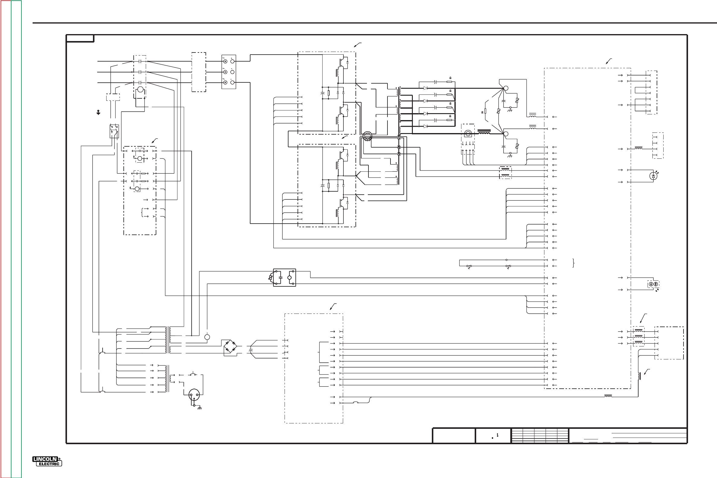
G-9
ELECTRICAL DIAGRAMS
POWER WAVE 455/POWER FEED 10
G-9
Return to Section TOC Return to Section TOC Return to Section TOC Return to Section TOC
Return to Master TOC Return to Master TOC Return to Master TOC Return to Master TOC
POWER WAVE 455 MACHINE SCHEMATIC - CODE 10555
50
224
220
3R
3W
THERMOSTAT
THERMOSTAT
222
223
226
FAN CONTROL (+)
FAN CONTROL (-)
(NORMALLY CLOSED)
51
RS232
NEG
NEG
C3
POS
444
X3A
351
H4A
612
612A
H3A
H2A
612B
H1A
H2
H1
352
350
H4
(380-415)
CB4
24V
6A
H3
CB2
5A
10J61
2J61
4J60
3J60
4J61
8J60
8J61
6J61
232
X4
604
1J32
2J32
4J32
5J32
601
612
CR1
6J31
5J31
50WT
2.7
10W
ELECTRODE
3181-1
S4
220V
RECEPTACLE
.022u
800V
N.A.
600V
MAIN TRANSFORMER T1
N.A.
RED/GREEN
STATUS
LED
S1 WIRE FEEDER
RECEPTACLE
ARCLINK -
ELECTRODE SENSE
N.A.
N.A.
3-19-99D
N.A.
N.B.
N.B.
S5 RS232
CONNECTOR
1B
RS232 RECEIVE
50
506
251
254
PRECHARGE CONTROL
202A
218
PHASE DETECT (5V=RUN)
202
206A
206
503
253
150V
239
234
80J
214
212
213
211
216
D
C
228 RS232 COMMON
X3A
TP4
274
273
444
226
228
-15Va
c
CONTROL
e
+5Ve
CAN
65VDC
NEG
1
6
(440-460)
3
(380-415)
H1
2
(220-230)
25000uF/100V
H5
(440-460) 0V
0VDC
E
D+40VDC
C
B
A
H4B
X3
(220-230)
H2
115V
(200-208)
H1
52V
FAN
4
B
(115V)
B
1
(200-208)
6
S
F
S
S
F
S
F
+13V
MAIN CONTACTOR CONTROL
INPUT BOARD
PRECHARGE RELAY
+13V
CONTROL BOARD COMMON
IGBT DRIVE (+)
RS232 +5V
+ELECTRODE VOLTAGE SENSE
- ELECTRODE VOLTAGE SENSE
CONTROL BOARD COMMON
CURRENT FEEDBACK
-15V
+15
PRIMARY CURRENT SENSE
PRIMARY CURRENT SENSE
IGBT DRIVE (+)
IGBT DRIVE (-)
CAPACITOR C5 OVERVOLTAGE (LOW=RUN)
CAPACITOR C5 UNDERVOLTAGE (LOW=RUN)
IGBT DRIVE (-)
CAPACITOR C4 OVERVOLTAGE (LOW=RUN)
CAPACITOR C4 UNDERVOLTAGE (LOW=RUN)
CONTROL BOARD COMMON
+13V
MAIN CONTACTOR CONTROL
+15V
+5V
CONTROL BOARD COMMON
-15V
+5V ARCLINK +5V
ARCLINK COMMON
.022u
800V
2.7
10W
2.7
10W
2.7
10W
12
15
17
16
18
15
16
SWITCH BOARD#2 (RIGHT)
C
SWITCH
LEAD
FILTER
L3A
L1A
ON
SW1
POWER
235
403
406
404
233
405
PRIMARY
CURRENT
SENSE
T2
2J91
TP3
CURRENT
TRANSDUCER
213
R1
1J91
.022u
800V
CHOKE
THERMOSTAT
GND
212
I OUT
+15V
216
-15V
211 3J91
-
OUTPUT RECTIFIER
THERMOSTAT
.022u
800V
C1/TP1
4J91
.05uF
600V
C4
(CAP "A")
3400uF
450V
506
C5
(CAP "B")
3400uF
450V
X3
T3
T1
9J23
4J23
5J23
14J23
7J23
13J23
6J23
12J23
3J23
10J23
2J21
4J22
3J21
1J21
10J22
6J21
8J23
2J20
11J23
1J23
6J20
2J23
5J22
1J22
2J22
3j22
4J27
3J27
6J22
8J22
8J31
1J31
2J31
NOT USED
NOT USED
+5Vc
+
+
B
C2/TP2
160J
ELECTRODE
238
231
1J50
4J50
234
53
54
239
235
5J50
POS
POS
X5
X1
X2
H3A
H2A
H5
P80
P81
H5A
H4
0VDC FEEDER
H4A
H3
+40VDC FEEDER
TRANSFORMER T2
CB3
10A
X4
H5A
AUXILIARY
TRANSFORMER T1
SINGLE
PHASE
DETECT
NEG
NEG
AC1
NEG
L3
OFF
612B
SWITCH BOARD #1 (LEFT)
CR1
H1D
INPUT
LINE
FILTER
POS
1J60 2J60
T3
L2
H4B
L1
T2
G
T1
W
AC3
V
AC2
U
INPUT
RECTIFIER
POS
L1B
L3B
POWER BOARD
225
221
222
223
291
224A
232
274
273
ELECTRICAL SYMBOLS PER E1537
11-7-97JLV
3181-1
NOTES :
N.A. PC BOARD COMPONENTS SHOWN FOR REFERENCE
ONLY. ALL COMPONENTS ARE NOT SHOWN.
N.B. L4 IS WOUND ON ONE COMMON CORE.
B.S.
MACHINE SCHEMATIC
G3181
225
221
12-4-98
XB-UF
NONE
CONTROL BOARD
S2 VOLTAGE SENSE
RECEPTACLE
INVERTER WELDERS
2
3
4
5
6
7
4
3J25
2
1
20
4J25
1J25
4J20
7J22
9J22
2J24
4J24
5J27
1J27
8J20
4J21
8J21
7J31
4J31
3J31
11J31
12J31
51BK
11
238
604
231
CB1 10A
10J24
12J24
L4
L4
ARCLINK +
L2
3
L7
L4
ARCLINK +
FEEDER VOLTAGE SENSE
2W
2B
THERMAL LED
21A
THERMAL LED
WORK VOLTAGE SENSE
67A
52
51
1W
ARCLINK -
RS232 COMMON
RS232 TRANSMIT
STATUS LED (HI FOR RED)
STATUS LED (HI FOR GREEN)
403 3J40
406 6J40
404 4J40
233 1J40
405 5J40
A
+
503 3J50
6J50
TESTVa
Vcc(+15)
3W
+15Va
-
+5Va
WELD AND
3R
CURRENT
GND a
+
SOLID
STATE
RELAY
+
320V
160J
.05uF
13
F
14
OUTPUT DIODES
D1-D4
320V
MAIN CHOKE L1
P91
MANUFACTURING TOLERANCE PER E2056
OWNED BY
G
Ch'ge. Sht. No.
SCALE
G
THE LINCOLN ELECTRIC CO.
SUBJECT
DR DATE
TYPE
EQUIP.
CLEVELAND, OHIO U.S.A.
CHK REF.
SHT.
SUP'S'D'G NO.
EMS
NOT TO BE REPRODUCED, DISCLOSED OR USED
WITHOUT THE EXPRESS PERMISSION OF
t
UNLESS OTHERWISE SPECIFIED TOLERANCE
ON 2 PLACE DECIMALS IS .02
ON 3 PLACE DECIMALS IS .002
WITH PUBLISHED STANDARDS.
ON ALL ANGLES IS .5 OF A DEGREE
MATERIAL TOLERANCE (" ") TO AGREE
AND IS
THE LINCOLN ELECTRIC CO.
THE LINCOLN ELECTRIC CO.
THIS SHEET CONTAINS PROPRIETARY INFORMATION
YELLOW
THERMAL
LED
5J60
NOTE: This diagram is for reference only. It may not be accurate for all machines covered by this manual.
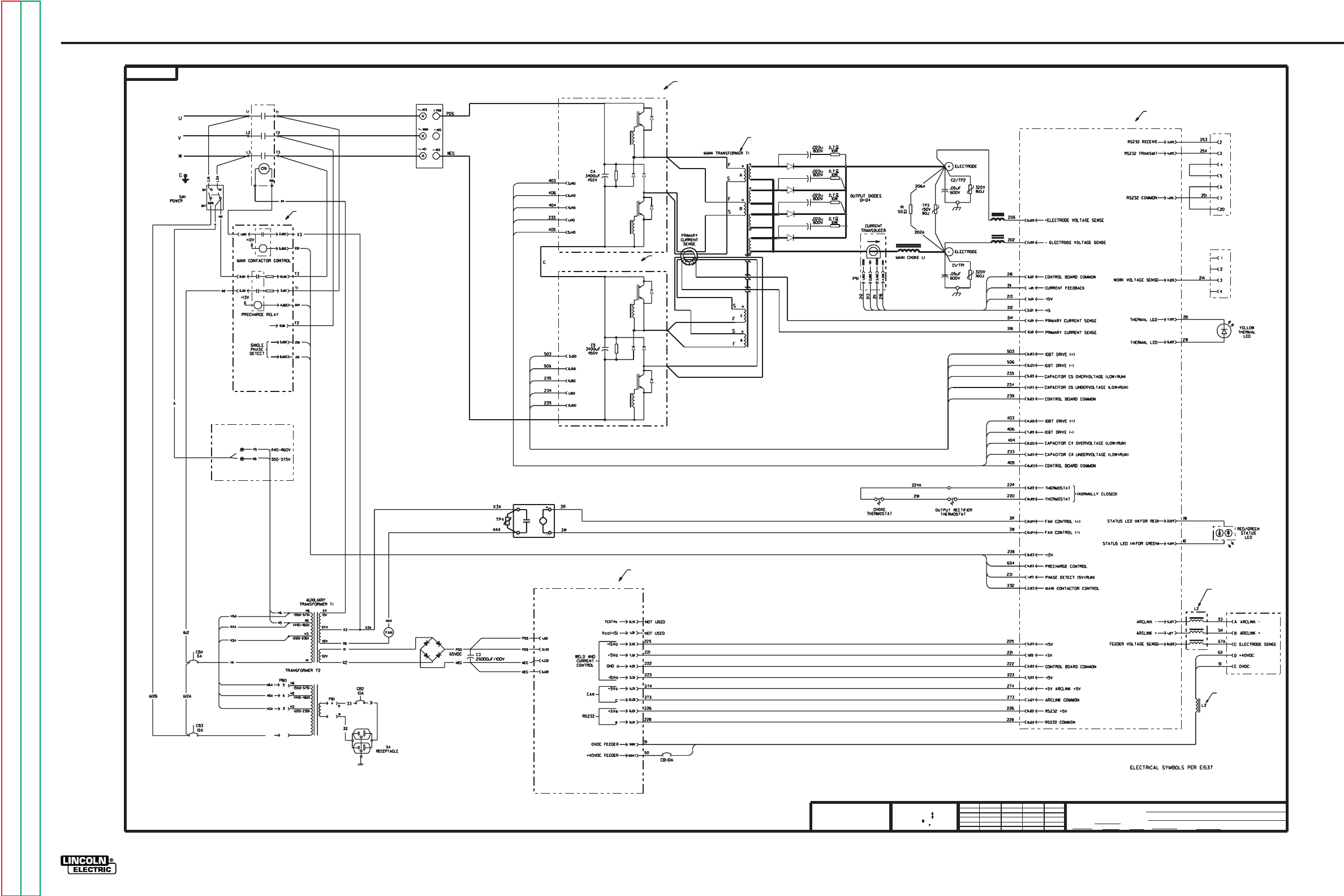
G-10
ELECTRICAL DIAGRAMS
POWER WAVE 455/POWER FEED 10
G-10
Return to Section TOC Return to Section TOC Return to Section TOC Return to Section TOC
Return to Master TOC Return to Master TOC Return to Master TOC Return to Master TOC
POWER WAVE 455 MACHINE SCHEMATIC - CODE 10553
1
H1A H1
1
(115V)
NOTES :
N.A. PC BOARD COMPONENTS SHOWN FOR REFERENCE ONLY.
ALL COMPONENTS ARE NOT SHOWN.
N.B. L2 IS WOUND ON ONE COMMON CORE.
N.C. T1 PRIMARY CONNECTIONS SHOWN FOR REFERENCE ONLY.
SEE WIRING DIAGRAM FOR 460/575 SWITCHING.
N.C.
N.A.
N.A.
N.A.
N.A.
N.A.
N.B.
MANUFACTURING TOLERANCE PER E2056
OWNED BY
G
Ch'ge. Sht. No.
SCALE
G
THE LINCOLN ELECTRIC CO.
SUBJECT
DR DATE
TYPE
EQUIP.
CLEVELAND, OHIO U.S.A.
CHK REF.
SHT.
SUP'S'D'G NO.
EMS
NOT TO BE REPRODUCED, DISCLOSED OR USED
WITHOUT THE EXPRESS PERMISSION OF
UNLESS OTHERWISE SPECIFIED TOLERANCE
ON 2 PLACE DECIMALS IS .02
ON 3 PLACE DECIMALS IS .002
WITH PUBLISHED STANDARDS.
ON ALL ANGLES IS .5 OF A DEGREE
MATERIAL TOLERANCE (" ") TO AGREE
AND IS
THE LINCOLN ELECTRIC CO.
THE LINCOLN ELECTRIC CO.
THIS SHEET CONTAINS PROPRIETARY INFORMATION
N.B.
S5 RS232
CONNECTOR
S2 VOLTAGE SENSE
RECEPTACLE
NONE
INVERTER WELDERS
11-4-98
3181-2
K.J.
3-19-99D
12-18-98A
MACHINE SCHEMATIC
XA
JLJ G3181-1
SWITCH BOARD#2 (RIGHT)
INPUT BOARD
AUX. RECONNECT
+
+
+
SWITCH BOARD #1 (LEFT)
CR1
INPUT
RECTIFIER
3181-2
POWER BOARD
SOLID
STATE
RELAY
S1 WIRE FEEDER
RECEPTACLE
CONTROL BOARD
NOTE: This diagram is for reference only. It may not be accurate for all machines covered by this manual.
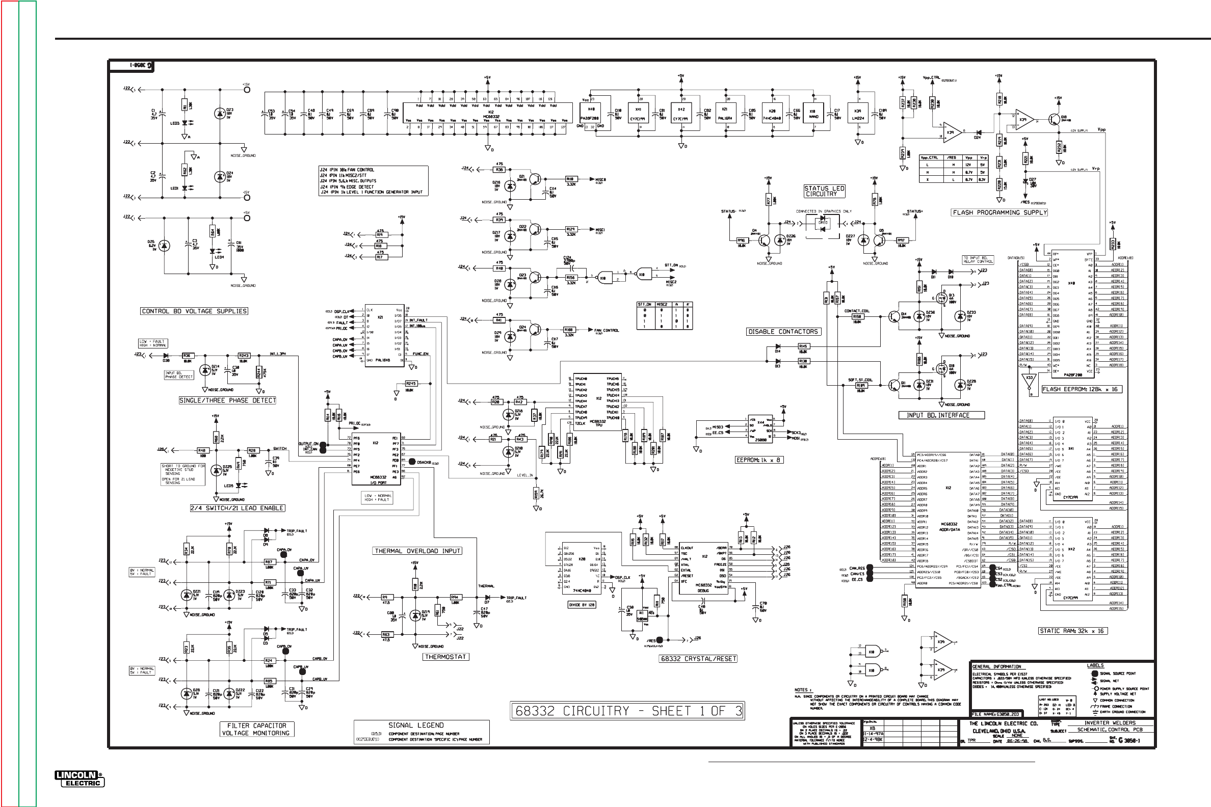
G-11
ELECTRICAL DIAGRAMS
POWER WAVE 455/POWER FEED 10
POWER WAVE 455 CONTROL PC BOARD SCHEMATIC (1 of 3)
G-11
Return to Section TOC Return to Section TOC Return to Section TOC Return to Section TOC
Return to Master TOC Return to Master TOC Return to Master TOC Return to Master TOC
NOTE: Lincoln Electric assumes no responsibility for liablilities resulting from board level troubleshooting. PC Board repairs will invalidate your factory warranty. Individual Printed Circuit Board Components are not available from Lincoln Electric. This information is pro-
vided for reference only. Lincoln Electric discourages board level troubleshooting and repair since it may compromise the quality of the design and may result in danger to the Machine Operator or Technician. Improper PC board repairs could result in damage to the
machine.

G-12
ELECTRICAL DIAGRAMS
POWER WAVE 455/POWER FEED 10
G-12
Return to Section TOC Return to Section TOC Return to Section TOC Return to Section TOC
Return to Master TOC Return to Master TOC Return to Master TOC Return to Master TOC
POWER WAVE 455 CONTROL PC BOARD SCHEMATIC (2 of 3)
NOTE: Lincoln Electric assumes no responsibility for liablilities resulting from board level troubleshooting. PC Board repairs will invalidate your factory warranty. Individual Printed Circuit Board Components are not available from Lincoln Electric. This information is pro-
vided for reference only. Lincoln Electric discourages board level troubleshooting and repair since it may compromise the quality of the design and may result in danger to the Machine Operator or Technician. Improper PC board repairs could result in damage to the
machine.
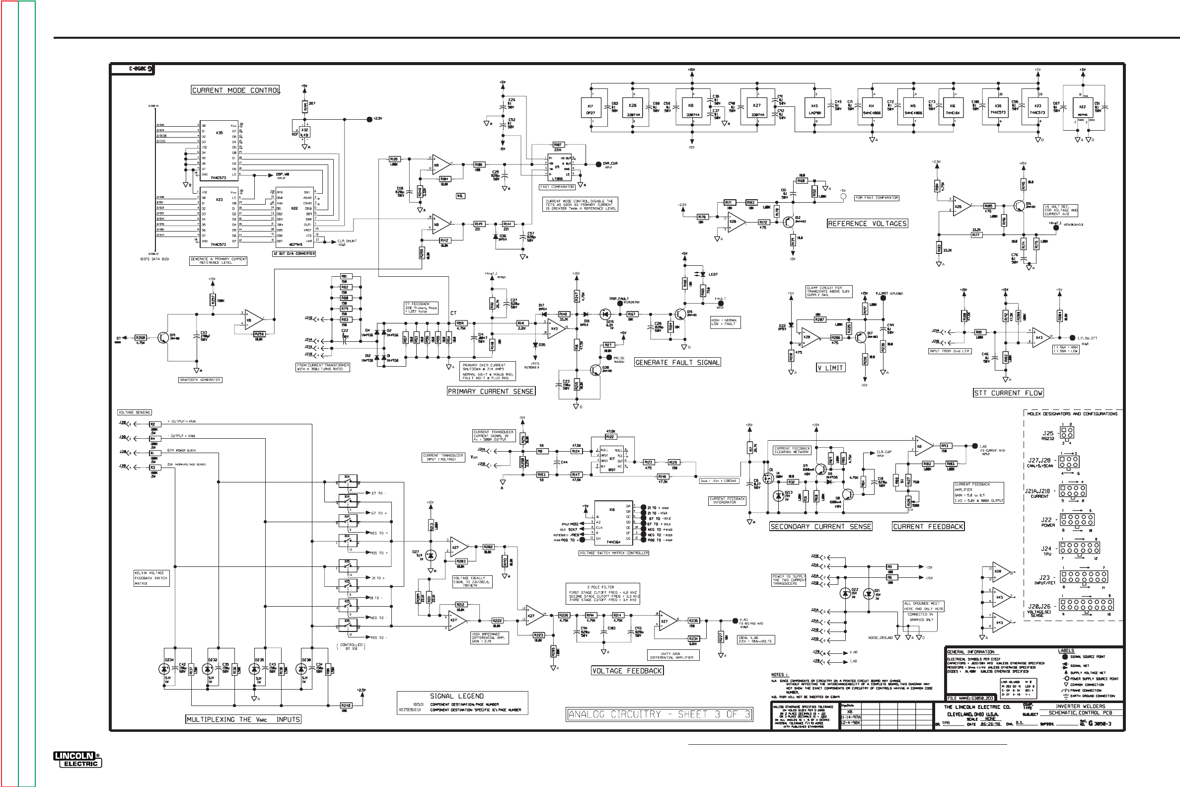
G-13
ELECTRICAL DIAGRAMS
POWER WAVE 455/POWER FEED 10
G-13
Return to Section TOC Return to Section TOC Return to Section TOC Return to Section TOC
Return to Master TOC Return to Master TOC Return to Master TOC Return to Master TOC
POWER WAVE 455 CONTROL PC BOARD SCHEMATIC (3 of 3)
NOTE: Lincoln Electric assumes no responsibility for liablilities resulting from board level troubleshooting. PC Board repairs will invalidate your factory warranty. Individual Printed Circuit Board Components are not available from Lincoln Electric. This information is pro-
vided for reference only. Lincoln Electric discourages board level troubleshooting and repair since it may compromise the quality of the design and may result in danger to the Machine Operator or Technician. Improper PC board repairs could result in damage to the
machine.
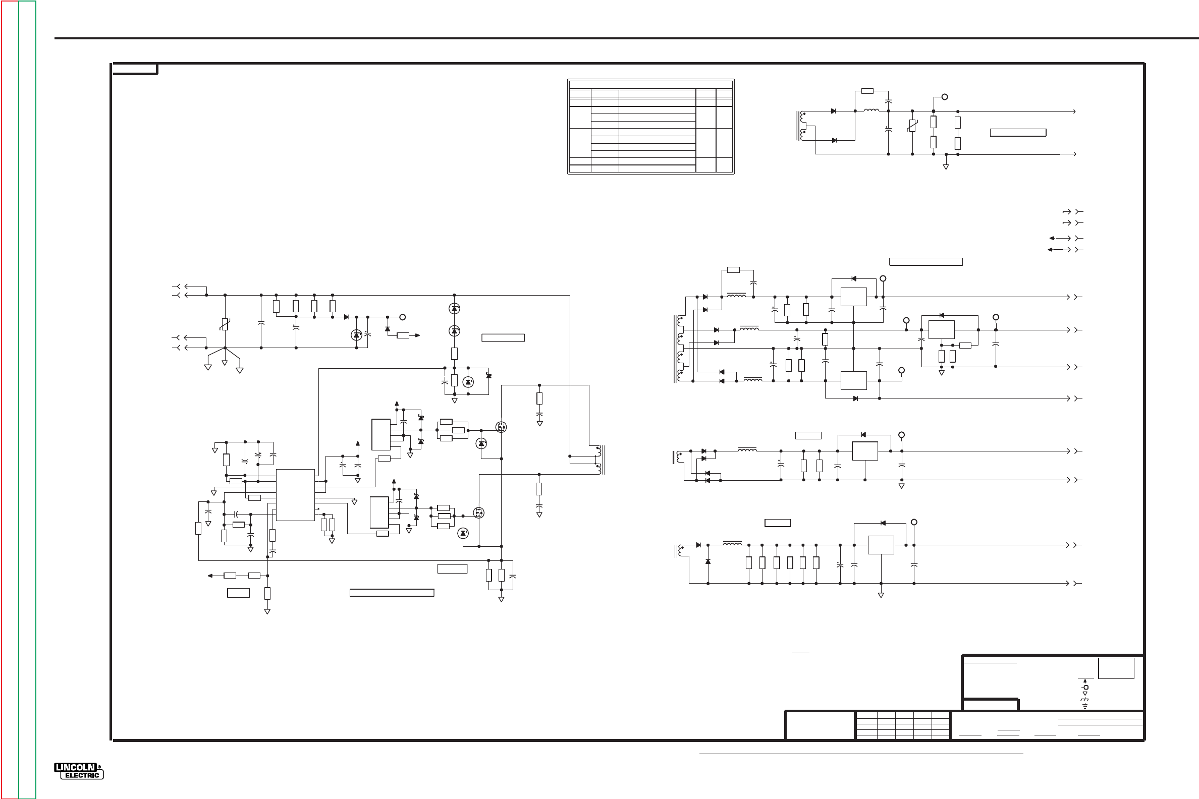
G-14
ELECTRICAL DIAGRAMS
POWER WAVE 455/POWER FEED 10
G-14
Return to Section TOC Return to Section TOC Return to Section TOC Return to Section TOC
Return to Master TOC Return to Master TOC Return to Master TOC Return to Master TOC
POWER WAVE 455 POWER PC BOARD SCHEMATIC
FEEDBACK
PRI. CURRENT
50V
0.1
C29
G
D
S
250V
38A
Q3
3.32K
R23
4.7
35V
C8
GND
IN
OUT
X8
GND
IN
OUT
X2
D23
PRI.
T1
7t
7t
4
7
5
6
3.32K
R54
3.32K
R55
3.32K
R52
50V
0.1
C11
1N4936
D12
1N4936
D13
J31
3
J31
12
50V
0.1
C1
J31
6
J31
11
SEC.
8t
T1
10
11
50V
0.1
C9
3.32K
R24
1W
16V
DZ2
50V
0.1
C24
+5Ve
c
SEC.
2t
T1
17
18
3.32K
R53
D1
400V
.0022
C30
1W
16V
DZ3
G
D
S
250V
38A
Q2
10W
4.7
R41
+40Vwf
PWM
15.0K
R31
50V
0.1
C18
68.1K
R19
2.43K
R17
CLIM
Vref
SYNC
OUTA
GND
Vc
OUTB
Vin
SHUT
RTCT
COMP
V-
V+
I+
I-
SG3846
X4
8
2
1
3
4
5
6
7
16
14
13
12
11
10
9
15
20V
1.8
C21
3.32K
R20
50V
820p
C27
133K
R32
2.21K
R34
15.0K
R18
750
R30
50V
2700p
C17
100V
22p
C23
1.50K
R21
20V
1.8
C22
100V
100p
C28
22.1K
R22
82.5K
R36
VOLTAGE
FEEDBACK
J32
1
51
.47mH
L7
J31
10
10W
100
R50
10W
100
R40
10W
100
R43
10W
100
R51
15J
50V
TP1
33
100V
C4
400V
.0047
C12
SEC.
B
8t
8t
A
C
T1
B2
15A
600V
D21
15A
600V
D20
B1
J31
9
J31
1
J31
8
Wire
Vcc(+15)
TESTVa
comF
+40Vwf
WIRE FEEDER POWER
50
WELD & CURRENT CONTROL
GND
CTRL
T1
e
a
WELD & CURRENT CONTROL
+5Va
+15Va
comF
c
+5Vc
+40Vf
-15Va
RS 232
+5Ve
WELD & CURRENT CONTROL
CAN
WIRE FEEDER
WELD & CURRENT CONTROL
INVERTER POWER SUPPLIES
USE
VOLTAGE
AMPH.
BRD
T1
T1
CTRL
TRANS
Feeder
"WT"
To
Test Points
"BK"
10W
4.7
R39
G
3026
L- 8
T- 1
VOLTAGE NET
FRAME CONNECTION
DATE
SCALE
CLEVELAND, OHIO U.S.A.
DR.
2-21-97
CHK.
THE LINCOLN ELECTRIC CO.
LC
NONE
Q- 3
TYPE
SUP'S'D'G.
EQUIP.
R- 55
LAST NO. USED
DZ- 6
C- 36
TP- 2
SUBJECT
LABELS
X- 8
D- 26
(
.022/50V
NUMBER.
NOTES :
WITHOUT AFFECTING THE INTERCHANGEABILITY OF A COMPLETE BOARD, THIS DIAGRAM MAY
N.A. SINCE COMPONENTS OR CIRCUITRY ON A PRINTED CIRCUIT BOARD MAY CHANGE
NOT SHOW THE EXACT COMPONENTS OR CIRCUITRY OF CONTROLS HAVING A COMMON CODE
CAPACITORS =
GENERAL INFORMATION
1/4W
Ch'ge.Sht.No.
ELECTRICAL SYMBOLS PER E1537
RESISTORS = Ohms (
G
SHT.
NO.
EARTH GROUND CONNECTION
3026
POWER SUPPLY SOURCE POINT
SUPPLY
COMMON CONNECTION
UNLESS OTHERWISE SPECIFIED)
(UNLESS OTHERWISE SPECIFIED)
DIODES =
1A, 400V
MFD
UNLESS OTHERWISE SPECIFIED)
FILE: G3026_2E1
Vin + Vc
OUT
GND
N.I. IN
INV IN
X6
10.0
R44
Vcc(+15)
Vcc(+15)
35V
4.7
C34
12.1K
R37
1.0A
30V
D24
475
R38
SWITCH_GND
1.0A
30V
D25
10.0
R45
50V
0.1
C32
1.0A
30V
D14
10.0
R47
10.0
R49
1.0A
30V
D15
10.0
R48
10.0
R46
Vin + Vc
OUT
GND
N.I. IN
INV IN
X5
.1
7W
R28
50V
0.1
C35
50V
0.1
C33
.1
7W
R27
475
R35
PRIMARY SWITCHING CIRCUIT
J31
2
400V
.001
C15
J31
4
3A
600V
D6
3A
600V
D9
1mH
L3
50V
0.1
C10
2.21K
R25
50V
0.1
C2
2.21K
R2
GND
IN
OUT
X3
OUT
IN
GND
X7
2.21K
R1
1mH
L4
1N4936
D10
1N4936
D11
3A
600V
D7
1mH
L5
4.7
35V
C5
3A
600V
D8
2.21K
R26
50V
0.1
C6
50V
0.1
C13
243
R11
ADJ
IN
OUT
X1
1.50K
R12
4.7
35V
C25 D2
50V
0.1
C26
4.7
35V
C3
J31
7
+15Va
D4
TESTVa
1.50K
R13
1.00K
R9
+5Va
-15Va
a
500mA
500mA
50V
0.1
C19
CAN
125mA
+5Vc
681
R15
1N4936
D18
1N4936
D17
1mH
L8
1N4936
D16
1N4936
D19
1mH
L6
Board
681
R16
e
To
J31
5
150
30mA
RS232
1000
35V
C14
Control
5W
20
R33
J32
4
SEC.
T1
2t
2t
2t
2t
12
14
16
15
13
D22
1.0A
30V
D26
1.00K
R8
Vcc(+15)
1W
3.3V
DZ6
1W
43V
DZ4
10W
4.7
R42
4.75K
R7
PROTECTION CIRCUIT
OVER/DOUBLE VOLTAGE
SWITCH_GND
400V
.0022
C31
1W
43V
DZ5
50V
0.1
C20
+40Vwf
J32
5
4.7
35V
C16
5W
1500
R4
5W
1500
R3
Vcc(+15)
1N4007
D3
5W
1500
R6
5W
17V
DZ1
5W
1500
R5
160J
320V
TP2
50
25V
C36
5W
270
R14
comF
65 Vdc +/- 20%
1N4007
D5
J32
2
630Vdc
.47
C7
46VAC
Rect.& Filtered
INVERTER WELDERS
SCHEMATIC, POWER PCB
KJ
XC-RW
11-14-97A
12-4-98A
NOTE: Lincoln Electric assumes no responsibility for liablilities resulting from board level troubleshooting. PC Board repairs will invalidate your factory warranty. Individual Printed Circuit Board Components are not available from Lincoln Electric. This information is pro-
vided for reference only. Lincoln Electric discourages board level troubleshooting and repair since it may compromise the quality of the design and may result in danger to the Machine Operator or Technician. Improper PC board repairs could result in damage to the
machine.
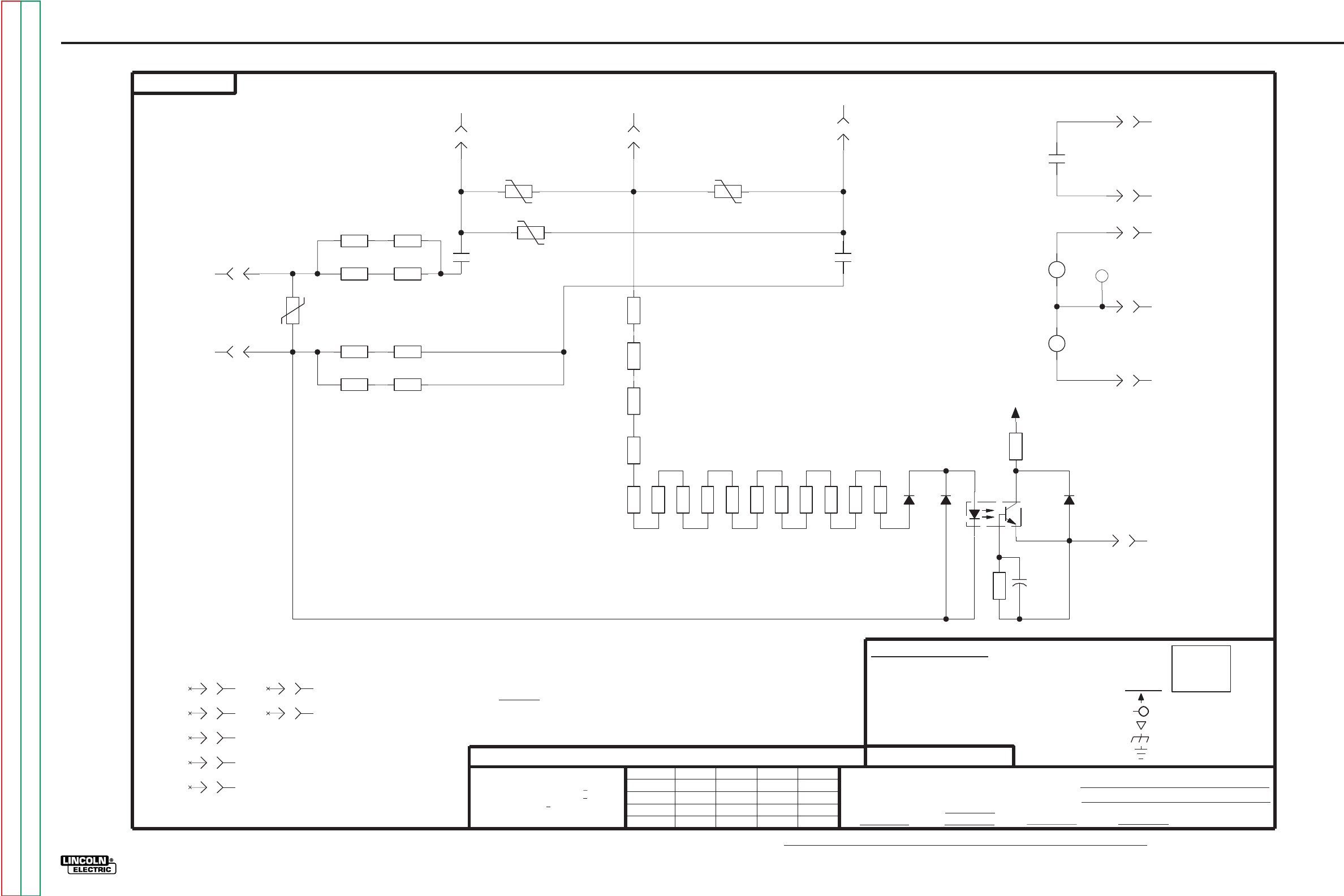
G-15
ELECTRICAL DIAGRAMS
POWER WAVE 455/POWER FEED 10
G-15
Return to Section TOC Return to Section TOC Return to Section TOC Return to Section TOC
Return to Master TOC Return to Master TOC Return to Master TOC Return to Master TOC
POWER WAVE 455 INPUT PC BOARD SCHEMATIC
5-17-96
SINGLE PHASE DETECT
NOTES :
CHK.
1A, 400V
CAPACITORS =
1A
1500V
D2
267K
R4
DIODES =
J60
7
WITH PUBLISHED STANDARDS
FILENAME: M17921_3DA
.022/50V
J61
3
J61
9
CENTER LEG TO OUTSIDE LEG OF INPUT
UNUSED PINS
D3
3.01K
R19
3.01K
R23
J60
8
3.01K
R20
MFD
RESISTORS = Ohms (
THE LINCOLN ELECTRIC CO.
3.01K
R21
J61
7
3.01K
R13
3.01K
R17
3.01K
R16
JLV
J60
6
CLEVELAND, OHIO U.S.A.
3.01K
R15
ELECTRICAL SYMBOLS PER E1537
3.01K
R14
SUP'S'D'G.
3.01K
R12
3.01K
R18
DATE
3.01K
R11
D1
475
R5
50V
.022
C1
CNY17-3V
OCI1
42
1
6
5
J61
1
DR.
ON HOLES SIZES PER E-2056
3
D-
LABELS
LAST NO. USED
M
1
C-
R-
M
NO.
SHT.
SUPPLY
FRAME CONNECTION
TP- 4
CR- 2
ON ALL ANGLES IS + .5 OF A DEGREE
SUBJECT
TYPE
EQUIP.
NONE
1/4W
(
UNLESS OTHERWISE SPECIFIED)
UNLESS OTHERWISE SPECIFIED)
(UNLESS OTHERWISE SPECIFIED)
UNLESS OTHERWISE SPECIFIED TOLERANCE
GENERAL INFORMATION
THE LINCOLN ELECTRIC CO.
NOT SHOW THE EXACT COMPONENTS OR CIRCUITRY OF CONTROLS HAVING A COMMON CODE
AND IS NOT TO BE REPRODUCED, DISCLOSED OR USED WITHOUT THE EXPRESS PERMISSION OF
WITHOUT AFFECTING THE INTERCHANGEABILITY OF A COMPLETE BOARD, THIS DIAGRAM MAY
ON 3 PLACE DECIMALS IS + .OO2
THE LINCOLN ELECTRIC CO.
ON 2 PLACE DECIMALS IS + .O2
MATERIAL TOLERANCE ("t") TO AGREE
THIS SHEET CONTAINS PROPRIETARY INFORMATION OWNED BY
N.A. SINCE COMPONENTS OR CIRCUITRY ON A PRINTED CIRCUIT BOARD MAY CHANGE
Ch'ge.Sht.No.
NUMBER.
SCALE
OCI- 1
25
EARTH GROUND CONNECTION
COMMON CONNECTION
POWER SUPPLY SOURCE POINT
VOLTAGE NET
17921
J61
5
J61
2
J60
3
10W
100
R10
3.01K
R24
10W
100
R2
CR2
3.01K
R25
J61
8
CR1
J60
5
10W
100
R8
10W
100
R1
10W
100
R9
CR2
4
3
3.01K
R22
250J
660V
TP2
10W
100
R3
10W
100
R6
10W
100
R7
J61
6
CR2
6
5
+13V
+13V
CONTACTOR CONTROL
J61
10
J60
2
CR1
4
3
250J
660V
TP3
J61
4
250J
660V
TP1
J60
1
J60
4
PRE-CHARGE CONNECTIONS
VAC
CONTACTOR OUTPUT
Input
PRE-CHARGE CONTROL
COIL CONNECT
CONTACTOR
+13V FROM CONTROL BOARD
17921
M
250J
660V
TP4
INVERTER WELDERS
SCHEMATIC, INPUT PCB
XB-RW
11-14-97
2-27-98L
12-4-98A
NOTE: Lincoln Electric assumes no responsibility for liablilities resulting from board level troubleshooting. PC Board repairs will invalidate your factory warranty. Individual Printed Circuit Board Components are not available from Lincoln Electric. This information is pro-
vided for reference only. Lincoln Electric discourages board level troubleshooting and repair since it may compromise the quality of the design and may result in danger to the Machine Operator or Technician. Improper PC board repairs could result in damage to the
machine.
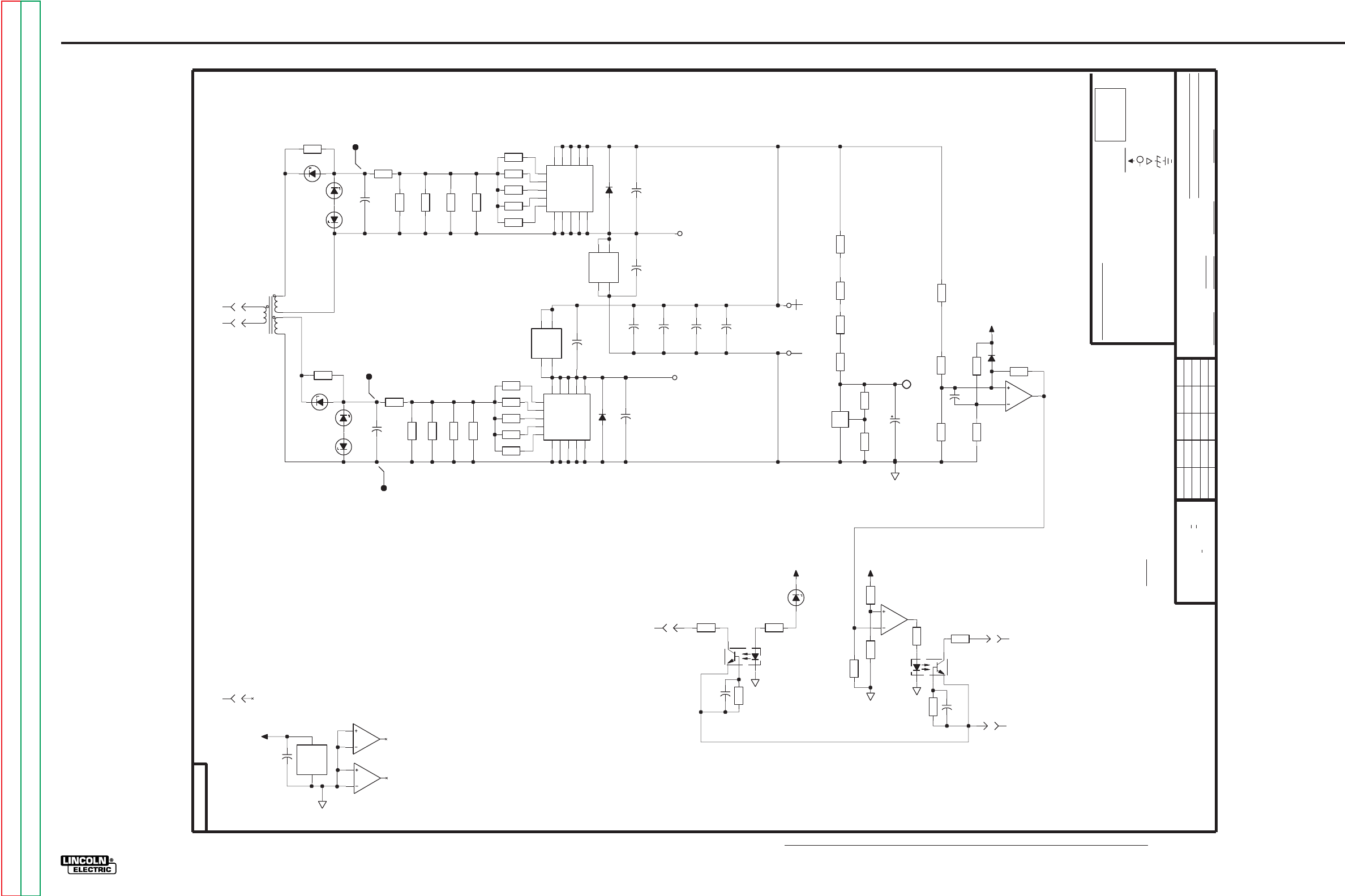
G-16
ELECTRICAL DIAGRAMS
POWER WAVE 455/POWER FEED 10
G-16
Return to Section TOC Return to Section TOC Return to Section TOC Return to Section TOC
Return to Master TOC Return to Master TOC Return to Master TOC Return to Master TOC
POWER WAVE 455 SWITCH PC BOARD SCHEMATIC - CODE 10372 & 10555
TRANSFORMER
PRIMARY
A
10.0
R26
1W
15V
DZ1
1W
6.2V
DZ3
2000V
.01
C1
10.0
R18
10.0
R19
10.0
R16
10.0
R20
1A
1000V
D1
1W
15V
DZ2
G1
C2
E4
C1
C3
G2
C4
E2 E5
C5
G3
E1
G5
G4
E3
A1
7
13
10
14
9
12
17
11
6
15
8
5
3
4
16
50V
.0047
C3
C2
A1
C1
A2
A1
19
18
1
2
10.0
R17
1.00K
R15
1.00K
R14
1.00K
R13
1.00K
R12
0.01
W2
11/12 OR 15/16
1000V
.0047
C10
OVERVOLTAGE
221
R21
J9
5
J9
4
CNY17-3V
OCI2
42
1
6
5
681K
R22
3.32K
R29
50V
.022
C2
10K
R28
50V
.022
C4
221
R3
1.21K
R5
X2
7
6
5
10K
R27
267K
R4
CNY17-3V
OCI1
4 2
1
6
5
J9
1
PROTECTION
1W
5.1V
DZ7
+15V+15V
RECONNECT
1.82K
R23
1000V
.22
C13
1000V
.22
C12
1000V
.22
C15
1000V
.22
C14
5W
2500
R31
332K
R24
+15V
+15V
X2
8
9
10
5W
2500
R30
6.19K
R9
18.2K
R8
D2
15.0K
R6
C11
562
R11
150K
R7
+
REF
-
TL431
X1
1
6
8
2.8K
R25
CAPACITOR
FILTER
20
27
35V
C6
1.00K
R37
1A
1000V
D3
1.00K
R36
1000V
.0047
C9
C2
A1
C1
A2
A2
19
18
1
2
2000V
.01
C8
50V
.0047
C7
DRIVE
GATE
GATE
T1
5
6
3
1
2
4
1.00K
R38
1.00K
R35
0.01
W1
10.0
R42
10.0
R40
10.0
R41
10.0
R39
G1
C2
E4
C1
C3
G2
C4
E2 E5
C5
G3
E1
G5
G4
E3
A2
7
13
10
14
9
12
17
11
6
15
8
5
3
4
16
5W
2500
R33
10.0
R43
1W
15V
DZ6
1W
6.2V
DZ4
1W
15V
DZ5
J9
6
J9
3
5W
2500
R32
PRIMARY
13/14 OR 17/18
TRANSFORMER
N.A. SINCE COMPONENTS OR CIRCUITRY ON A PRINTED CIRCUIT BOARD MAY CHANGE
NOT SHOW THE EXACT COMPONENTS OR CIRCUITRY OF CONTROLS HAVING A COMMON CODE
WITHOUT AFFECTING THE INTERCHANGEABILITY OF A COMPLETE BOARD, THIS DIAGRAM MAY
DATE
DR.
LC
2-10-97
RECONNECT
RESISTORS
BLEEDER
19
TYPE
SUBJECT
(
1A, 400V
SCALE
MFD
.022/50V
ELECTRICAL SYMBOLS PER E1537
1/4W
GENERAL INFORMATION
THE LINCOLN ELECTRIC CO.
(UNLESS OTHERWISE SPECIFIED)
NONE
CLEVELAND, OHIO U.S.A.
DIODES =
TO CONTROL BD.
(VOLTAGE PROTECTION)
(Pre-charge Shut-off)
C
UNLESS OTHERWISE SPECIFIED)
UNLESS OTHERWISE SPECIFIED)
EQUIP.
B
PWM
L
9904
FILENAME: L9904-4EA
LABELS
CAPACITORS =
RESISTORS = Ohms (
ON 2 PLACE DECIMALS IS + .O2
MATERIAL TOLERANCE ("t") TO AGREE
ON ALL ANGLES IS + .5 OF A DEGREE
UNLESS OTHERWISE SPECIFIED TOLERANCE
TO CONTROL BD.
(VOLTAGE PROTECTION)
(Trigger Loop)
WITH PUBLISHED STANDARDS
NUMBER.
Ch'ge.Sht.No.
ON 3 PLACE DECIMALS IS + .OO2
NOTES :
ON HOLES SIZES PER E-2056
NOTE: 203,206 BOLT ON WITH FILTER CAPS
NO.
CHK.
V450
SUP'S'D'G.
R-
LAST NO. USED
D-
OCI-
A-
2
T-
X-
SUPPLY
3
9904
2
VOLTAGE NET
COMMON CONNECTION
SWITCH SCHEMATIC
43
C-
7
SHT.
1
2
DZ-
FRAME CONNECTION
L
EARTH GROUND CONNECTION
POWER SUPPLY SOURCE POINT
15
J9
2
10.0
R34
150K
R10
C5
+15V
X2
1
2
3
LM224
X2
4
11
X2
14
13
12
xc
11-14-97A
3-27-98G
3-19-99C
NOTE: Lincoln Electric assumes no responsibility for liablilities resulting from board level troubleshooting. PC Board repairs will invalidate your factory warranty. Individual Printed Circuit Board Components are not available from Lincoln Electric. This information is pro-
vided for reference only. Lincoln Electric discourages board level troubleshooting and repair since it may compromise the quality of the design and may result in danger to the Machine Operator or Technician. Improper PC board repairs could result in damage to the
machine.
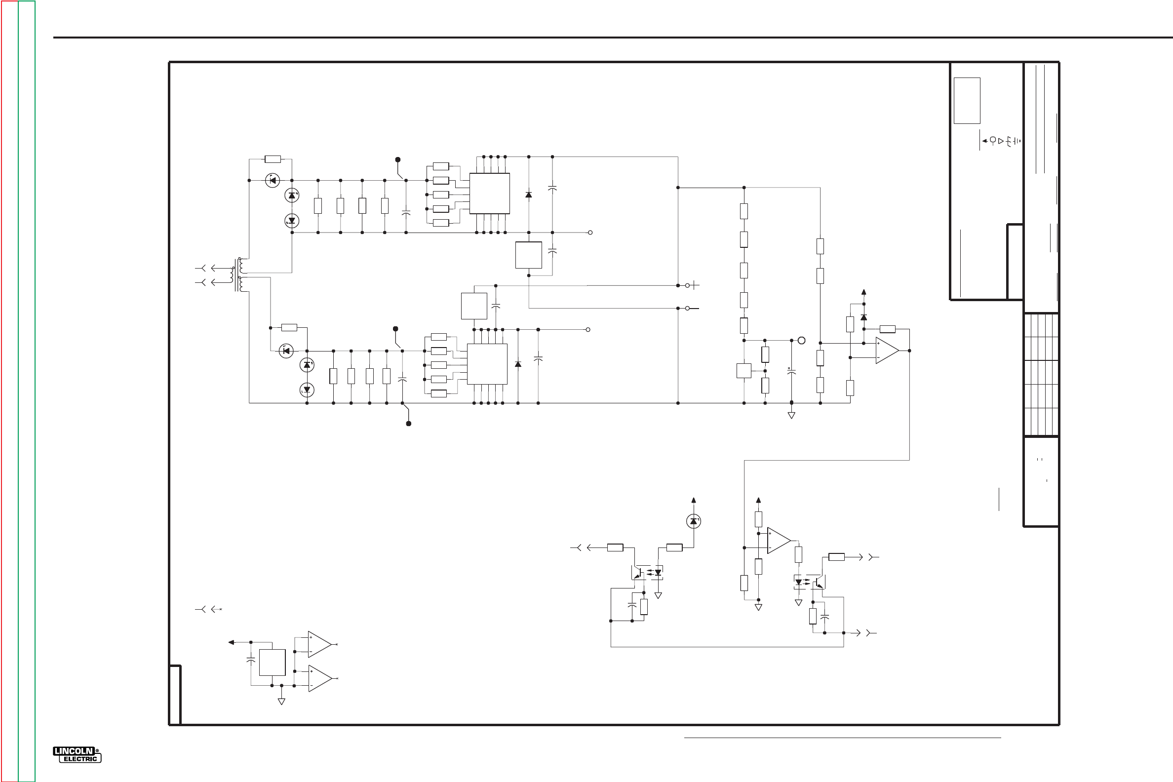
G-17
ELECTRICAL DIAGRAMS
POWER WAVE 455/POWER FEED 10
G-17
Return to Section TOC Return to Section TOC Return to Section TOC Return to Section TOC
Return to Master TOC Return to Master TOC Return to Master TOC Return to Master TOC
POWER WAVE 455 SWITCH PC BOARD SCHEMATIC - CODE 10553
+15V
50V
.022
C4
1.82K
R23
CNY17-3V
OCI2
42
1
6
5
681K
R22
3.32K
R29
6.19K
R9
5W
2500
R31
2.8K
R25
27
35V
C6
RECONNECT
5W
2500
R33
5W
2500
R32
5W
2500
R30
562
R11
+15V
5W
2500
R44
221K
R7
1.50K
R45
X2
8
9
10
16.5K
R8
332K
R24
15.0K
R6
D2
RESISTORS
BLEEDER
221K
R10
+15V
1W
5.1V
DZ7
10K
R27
X2
7
6
5
10K
R28
J9
2
OVERVOLTAGE
PROTECTION
TO CONTROL BD.
(VOLTAGE PROTECTION)
(Trigger Loop)
NOTE: 203,206 BOLT ON WITH FILTER CAPS
+
REF
-
TL431
X1
1
6
8
CAPACITOR
J9
4
221
R21
PWM
L
10666
J9
5
+15V
DRIVE
GATE
GATE
T1
5
6
3
1
2
4
J9
6
J9
3
B
C
10.0
R20
X2
1
2
3
10.0
R40
X2
14
13
12
1.00K
R36
A
50V
.0047
C3
1W
15V
DZ2
1W
6.2V
DZ3
10.0
R26
1.00K
R37
10.0
R39
10.0
R34
1W
15V
DZ5
1.00K
R35
1.00K
R14
1.00K
R13
1.00K
R12
10.0
R18
1.00K
R15
10.0
R17
10.0
R19
C5
10.0
R16
10.0
R42
10.0
R43
50V
.0047
C7
1W
6.2V
DZ4
LM224
X2
4
11
1W
15V
DZ1
1W
15V
DZ6
1.00K
R38
10.0
R41
TYPE
10666
DATE
COMMON CONNECTION
VOLTAGE NET
2
FILENAME: L10666_1AA
10
GENERAL INFORMATION
RESISTORS = Ohms (
CAPACITORS =
ELECTRICAL SYMBOLS PER E1537
C-
2
THE LINCOLN ELECTRIC CO.
1
NOT SHOW THE EXACT COMPONENTS OR CIRCUITRY OF CONTROLS HAVING A COMMON CODE
ON ALL ANGLES IS + .5 OF A DEGREE
UNLESS OTHERWISE SPECIFIED TOLERANCE
WITHOUT AFFECTING THE INTERCHANGEABILITY OF A COMPLETE BOARD, THIS DIAGRAM MAY
MATERIAL TOLERANCE ("t") TO AGREE
ON 2 PLACE DECIMALS IS + .O2
WITH PUBLISHED STANDARDS
NUMBER.
Ch'ge.Sht.No.
DIODES =
N.A. SINCE COMPONENTS OR CIRCUITRY ON A PRINTED CIRCUIT BOARD MAY CHANGE
ON 3 PLACE DECIMALS IS + .OO2
NOTES :
ON HOLES SIZES PER E-2056
UNLESS OTHERWISE SPECIFIED)
UNLESS OTHERWISE SPECIFIED)
(UNLESS OTHERWISE SPECIFIED)
NONE
FRAME CONNECTION
CLEVELAND, OHIO U.S.A.
EQUIP.
2-10-97
DR.
DZ-
7
1A, 400V
SHT.
L
NO.
POWER SUPPLY SOURCE POINT
EARTH GROUND CONNECTION
SUBJECT
SCALE
CHK.
SUP'S'D'G.
R-
LAST NO. USED
D-
OCI-
A-
2
T-
45
X-
SUPPLY
3
LABELS
(
1/4W
.022/50V
MFD
1000V
.0047
C10
1600V
.047
C1
G1
C2
E4
C1
C3
G2
C4
E2 E5
C5
G3
E1
G5
G4
E3
A2
A1
A2
C1
TRANSFORMER
G1
C2
E4
C1
C3
G2
C4
E2 E5
C5
G3
E1
G5
G4
E3
A1
1600V
.047
C8
267K
R4
1000V
.0047
C9
PRIMARY
FILTER
11/12 OR 15/16
PRIMARY
TRANSFORMER
13/14 OR 17/18
1A
1000V
D3
1.21K
R5
+15V
J9
1
50V
.022
C2
221
R3
CNY17-3V
OCI1
4 2
1
6
5
1A
1000V
D1
RECONNECT
(Pre-charge Shut-off)
TO CONTROL BD.
(VOLTAGE PROTECTION)
20
19
A1
A1
C1
LC/JLV
INVERTER WELDERS
SCHEMATIC, SWITCH PCB
XA
B.S.
12-18-98A
NOTE: Lincoln Electric assumes no responsibility for liablilities resulting from board level troubleshooting. PC Board repairs will invalidate your factory warranty. Individual Printed Circuit Board Components are not available from Lincoln Electric. This information is pro-
vided for reference only. Lincoln Electric discourages board level troubleshooting and repair since it may compromise the quality of the design and may result in danger to the Machine Operator or Technician. Improper PC board repairs could result in damage to the
machine.
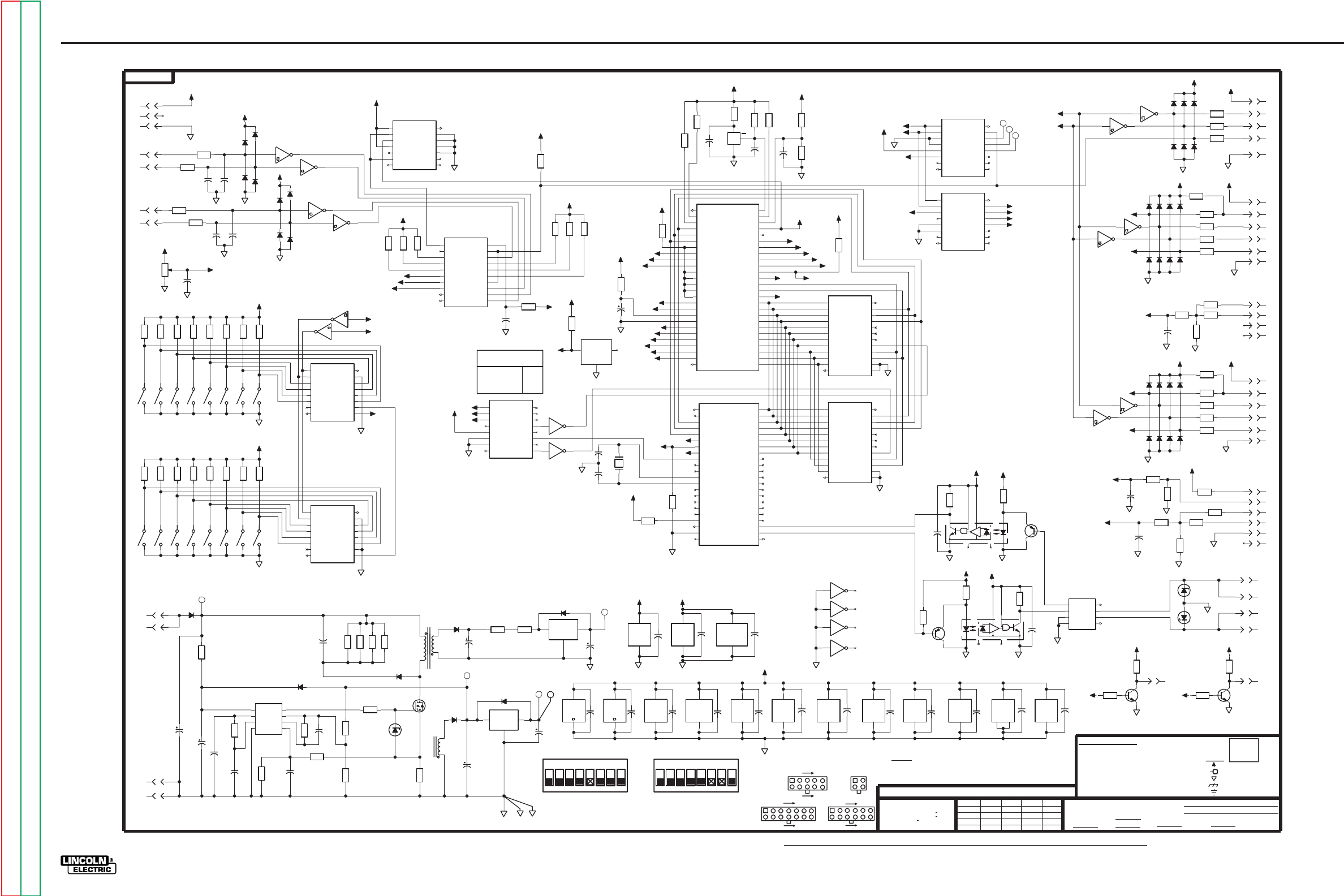
G-18
ELECTRICAL DIAGRAMS
POWER WAVE 455/POWER FEED 10
G-18
Return to Section TOC Return to Section TOC Return to Section TOC Return to Section TOC
Return to Master TOC Return to Master TOC Return to Master TOC Return to Master TOC
POWER FEED 10 MOTHER CONTROL PC BOARD SCHEMATIC
540
500N
500D
/SS
PA3
+5V
/IRQ
SCK
A15
MISO
XTAL
A14
MOSI
1.0
35V
C44
1.00K
R15
4.75K
R90
C25
4.75K
R20
1.00K
R19
1.82K
R23
26.7K
R21
C24
2.21K
R18
50V
0.1
C23
10K
R22
S-8054HN
Vdd
Vss
RES
X17
500D
10K
R17
X24
5
6
X24
13
12
1
26
PA6
VRH
PA5
MODA
R//W
PA4
PA1
PA2
PA0
VRL
PE2
PD0
PE5
PE0
PE7
PA7
Vss
A13
PE6
AS
PD1
E
Vdd
MODB
PE4
PE3
AD6
AD4
A10
AD5
/RESET
A12
AD3
AD0
AD1
A14
A11
AD2
/SS
PA3
A15
/IRQ
PE1
EXTAL
XTAL
MISO
/XIRQ
MOSI
SCK
AD7
A8
A9
MC68HC11E1
X9
4
3
2
5
52
29
30
32
51
6
50
49
27
20
21
28
46
47
43
44
33
34
48
37
40
41
42
16
15
11
35
14
12
9
13
39
36
38
10
31
25
19
24
45
18
22
23
8
7
17
130
8.0MHz
Y1
4.75K
R96
4.75K
R95
DATA
GND
NC
DS2501
X8
100V
22p
C48
100V
22p
C47
X24
9 8
X24
11
10
4.75K
R24
20
1
23
P2.3
Vcc
RX1
/INT
P2.6
P2.7
P2.2
P2.4
AN82527
XTAL1
CLK OUT
AS
TX1
E
READY
MODE0
R/W
XTAL2
/DSACKO
MODE1
Vss2
P2.5
/CS
/RESET
P2.0
P1.3
AD0
P1.6
AD3
AD1
AD5
AD6
AD7
P1.0
P1.1
P1.2
AD4
P1.4
P1.5
P2.1
AD2
P1.7
Vss1
TX0
RX0
X23
25
11
10
24
8
9
7
29
44
28
30
6
18
27
5
13
14
12
21
19
4
43
41
42
2
40
3
16
15
31
26
35
39
38
34
17
33
22
32
37
36
12
24
A/D0
A/D2
A/D7
R/W
A/D1
A/D4
/WC
A8
A/D3
A/D5
A/D6
A9
GND
N/C
N/C
N/C
SEL
A10
CE
A11
X68C64
AS
E
Vcc
A12
X7
7
21
20
9
15
8
11
17
10
14
13
23
18
22
3
1
4
19
2
16
6
5
12
24
A/D0
A/D2
A/D7
R/W
A/D1
A/D4
/WC
A8
A/D3
A/D5
A/D6
A9
GND
N/C
N/C
N/C
SEL
A10
CE
A11
X68C64
AS
E
Vcc
A12
X16
7
21
20
9
15
8
11
17
10
14
13
23
18
22
3
1
4
19
2
16
6
5
4.75K
R12
4.75K
R13
4.75K
R10
4.75K
R11
8
16
C
/G2B
B
/G2A
74AC138
/Y5
/Y3
/Y7
A
G1
/Y6
/Y2
/Y4
/Y1
GND
Vcc
/YO
X26
2
1
3
4
6
5
7
15
9
10
11
12
14
13
8
16
I3a
74AC153
S0
I2b
I0b
GND
Vcc
/Eb
I1b
I3b
Zb
/Ea
I2a
Za
S1
I0a
I1a
X22
9
13
15
14
2
6
10
3
7
12
11
4
5
1
50V
0.1
C29
500N
J4
11
+5V
4.75K
R40
500N
500N
X6
4
3
X6
2
1
J4
7
J4
9
J4
10
540
4.75K
R45
S2
15
2
500D
+5V
PE4
500D
SCK
S1LATCH
MOSI
500N
4.75K
R38
S2
16
1
S1
1
16
4.75K
R46
4.75K
R37
J4
12
S1
2
15
2.67K
R3
10K
CW
R5
3142
G
ENCODER SUPPLY
BURNBACK
DIP SWITCH 1
A
A
ENCODER 2
B
ENCODER 1
B
TRIMMER
POWER BUS
DIP SWITCH 2
-1
-2
556
-1
-2
J4
8
4.75K
R44
+40 VDC
500D
4.75K
R42
4.75K
R39
4.75K
R43
4.75K
R41
E
8
16
H
E
CLK1
74HC165
C
CLK2
Vcc
GND
QH
B
D
F
SS/PL
G
SA
/QH
A
X13
13
14
12
11
10
9
15
7
6
5
4
3
1
2
J4
3
500D
+5V
PA5
PA4
/SS
500D
500D
MISO
10.0K
R57
500D
SPARE
( HD ID )
SPARE
( HD ID )
GROUP ID
GROUP ID
WFS DISPLAY
3
75
6
4
RUN IN MODE
SPARE
ACCELERATION
ACCELERATION
( MSB )
S1
RESERVED
ACCELERATION
( LSB )
RESERVED
MODE
500N
4 STEP CONFIG.
2
IPM / MPM
( EURO / US )
1
C
CLEVELAND, OHIO U.S.A.
500D
NONE
DR.
WITH PUBLISHED STANDARDS
MATERIAL TOLERANCE ("t") TO AGREE
LAST NO. USED
52
96
37
MOLEX CONNECTORS
1
2
3
S2
6
54
RESERVED
87
J4
( HD ID )
RESERVED
SHT.
7
14
1
8
SUPPLY
G
C-
SWG USER INTERFACE
TF
CHK.
2/15/96
DATE
AND IS NOT TO BE REPRODUCED, DISCLOSED OR USED WITHOUT THE EXPRESS PERMISSION OF
SUP'S'D'G.
R-
2
J1,J2
3
4
J5
VOLTAGE NET
D-
COMMON CONNECTION
FRAME CONNECTION
LABELS
S2
10
7
4.75K
R48
4.75K
R51
-6
S2
13
4
-5
-3
S1MISO
-8
-5 -7 -8
-7
-6
-3
-4
-4
4.75K
R50
S2
11
6
S2
9
8
S2
12
5
4.75K
R49
4.75K
R52
4.75K
R47
+5V
500D
500D
S1
4
13
S1
8
9
S1
7
10
S1
6
11
S2
14
3
S1
5
12
8
16
H
E
CLK1
74HC165
C
CLK2
Vcc
GND
QH
B
D
F
SS/PL
G
SA
/QH
A
X14
13
14
12
11
10
9
15
7
6
5
4
3
1
2
S1
3
14
MOTHER BD. SCHEMATIC
3.32K
R88
681
R89
J3
12
1W
6.2V
DZ3
MODE 1
MODE 3
BUS L
RED
LED
J4
14
BUS L
J3
9
EQUIP.
1W
6.2V
DZ2
SUBJECT
Q5
2N4401
J2
2
J1
1
J1
2
POT COMMON
TYPE
J3
11
J3
10
BUS H
J2
1
512
500N
512
500N
500N
+5VN
500N
500N
512
500N 500N
PD1
500D
ISO COM
512
500N
+5VN
500N
LED
BLACK
DIAGNOSTIC
GREEN
+12.8 VDC
WHITE
DATA BUS
BUS H
1.82K
R68
4.32K
R70
3142
POWER SUPPLY SOURCE POINT
MEMORY/DP
NO.
1.00K
R71
+12.8 VDC
512
4.75K
R7
D1
2.67K
R2
C17
2.67K
R1
D3
C18
X6
12
13
D2
D7
D8
C20
+5V
+5VN
+5VN
500N
B
A
D
C
X6
89
D6
D5
C19
X6
10
11
F
2.67K
R4
D4
4.75K
R8
X6
6
5
4.75K
R9
J1AMISO
+5V
SCK
500D
50V
0.1
C21
50V
0.1
C9
50V
0.1
C11
50V
0.1
C50
54HC74
X11
7
14
500D
MC68HC705J1
X10
10
9
50V
0.1
C12
74AC138
X26
16
8
74AC138
X12
16
8
Vdd
Vss
MC68HC11E1
X9
1
26
50V
0.1
C10
50V
0.1
C1
500D
/IRQ
XTAL
+5V
500D
+5V
50V
0.1
C7
8
5
485
DE
GND/RE
A
VCC
B
DI
RO
X1
2
7
4
3
1
6
50V
0.1
C30
3.32K
R86
74AC04
X24
14
7
Vss1
Vcc
Vss2
AN82527
X23
23
1
20
X68C64
Vcc
X16
Vss
24
12
50V
0.1
C52
50V
0.1
C16
50V
0.1
C51
ISO +5
+5V
PE2
Q4
2N4401
PD0
500D
+5V
ISO +5
ISO COM
ISO COM
500D
PE3
500D
ISO COM
512
500N
500N
1.00K
R59
475
R58
475
R55
1.00K
R54
NC NC
OCI1
5
2
8
3
6
4
1
7
Q1
2N4403
3.32K
R65
50V
0.1
C31
3.32K
R69
50V
0.1
C32
SWITCHING
512
10.0
R77
T1
10
9
1N4936
D33
4.7
35V
C34
GND
IN
OUT
X20
VCC
485
GND
X1
5
8
13.7K
R73
13.7K
R75
13.7K
R74
200V
.022
C33
1N4936
D31
18
15V
C35
13.7K
R72
D36
ISO +5
T1
4
2
ISO COM
ISO +5
1N4936
D32
ISO COM
A
10.0
R76
7
14
/Q1
CLOCK 1
SET 1
RESET 1
Q1
54HC74
RESET 2
N.C.
DATA 1
DATA 2
GND
Q2
CLOCK 2
VCC
SET 2
X11
10
1
11
4
2
3
6
9
13
12
5
8
8
16
C
/G2A
B
/Y4
74AC138
/Y5
/Y3
/G2B
A
G1
/Y6
/Y7
/Y2
/Y1
GND
Vcc
/YO
X12
2
1
3
11
6
4
5
15
9
10
13
12
14
7
+5V
10
9
MC68HC705J1
Vdd
PA7
OSC1
PA3
PA5
PA4
PA0
PA1
/IRQ
/RESET
PA2
Vss
PB0
PB1
PB3
PB5
PB4
PA6
PB2
OSC2
X10
20
5
6
19
18
16
14
15
11
12
4
7
1
13
8
2
17
3
1 11
500D
A15 A14
A13
HIGH
500D
C22
1.00K
R14
LOW
4.75K
R6
DECODE INFO
A15
A14
+5V
+5V
500D
+5V
500D
500D
PA7
+5V
+5V
A13
PA6
500D
+5V
PE3
PA5
PA6
A13
PD0
PA7
PD1
PE0
PA4
PA3
PE2
PE4
+5V
0 CAN
11
1
0
0
DISPLAY
X5
2
1
D15
B
MOLATCH
S1LATCH
S1MISO
LOMISO
MOMISO
J1AMISO
LOLATCH
PE0
MOMISO
MOLATCH
LOMISO
MOSI
SCK
LOLATCH
A
F
D
C
E
X5
12
13
X5
4
3
X5
6
5
X5
89
D19
X5
10
11
D23
D27
+5VN
D21
J5
4
J5
6
J4
6
J4
2
500N
512
500N
OPTION
MOSI
LATCH
SCK
LATCH
PROC. A
SCK
LATCH
+12.8 VDC
POT WIPER
+12.8 VDC
STD
POT SUPPLY
OPTION
LOWER
MISO
MOSI
MOSI
MISO
PROC. B
+12.8 VDC
+12.8 VDC
SCK
J5
7
1.00K
R36
1.82K
R33
4.32K
R35
3.32K
R34
50V
0.1
C26
J5
8
J5
10
J5
9
475
R63
475
R61
J3
7
475
R64
475
R32
J5
3
J4
5
J4
4
J5
2
J5
5
J5
1
D20 D22
D17
D16
D18
J4
1
D11
D10
D9
475
R62
10K
R28
10K
R60
475
R31
475
R29
475
R26
475
R27
D13
D12 D14
475
R25
475
R30
J3
8
J3
1
D26
D25
D29
100K
R66
D24
16.5K
R67
J3
5
D28
J3
6
J3
2
J3
4
J3
3
D30
1
50V
0.1
C5
18
15V
C43
X68C64
Vcc
X7
Vss
24
12
HEXINV
X6
14
7
HEXINV
X5
14
7
500P
50V
2700p
C39
6.19K
R82
26.7
R84
1W
16V
DZ1
4A
200V
D34
D35
+5V
8
50V
2700p
C40
332
R81
VFB
CS
COMP
RT/CT
VCC
OUT
VREF
GND
X18
2
3
5
1
6
4
8
7
1.3K
R79
50V
2700p
C41
150K
R80
13.7K
R78
50V
0.1
C38
50V
0.1
C6
GND
IN
OUT
X19
3300
50V
C42
1.50K
R83
.5
5W
R85
T1
7
6
G
D
S
18A
200V
Q3
POWER SUPPLY
+5VN
B
+12.8 VDC
DIAGNOSTIC
Ch'ge.Sht.No.
SCALE
74HC165
X13
16
8
50V
0.1
C49
50V
0.1
C13
74AC153
X22
16
8
50V
0.1
C14
74HC165
X14
16
8
J4
13
33
100V
C36
D37
1N5402
20
50V
C37
Q2
2N4403
X24
3
4
X24
1
2
4.75K
R91
J1
3
J2
3
J1
4
J2
4
EARTH GROUND CONNECTION
MFD
(
1/4W
ON 2 PLACE DECIMALS IS + .O2
FILENAME: G3142_1BA
CAPACITORS =
THIS SHEET CONTAINS PROPRIETARY INFORMATION OWNED BY
UNLESS OTHERWISE SPECIFIED)
THE LINCOLN ELECTRIC CO.
ON 3 PLACE DECIMALS IS + .OO2
THE LINCOLN ELECTRIC CO.
.022/50V
UNLESS OTHERWISE SPECIFIED)
RESISTORS = Ohms (
(UNLESS OTHERWISE SPECIFIED)
WITHOUT AFFECTING THE INTERCHANGEABILITY OF A COMPLETE BOARD, THIS DIAGRAM MAY
N.A. SINCE COMPONENTS OR CIRCUITRY ON A PRINTED CIRCUIT BOARD MAY CHANGE
NOT SHOW THE EXACT COMPONENTS OR CIRCUITRY OF CONTROLS HAVING A COMMON CODE
NOTES :
NUMBER.
ON ALL ANGLES IS + .5 OF A DEGREE
THE LINCOLN ELECTRIC CO.
DIODES =
1A, 400V
+12.8 VDC
ELECTRICAL SYMBOLS PER E1537
UNLESS OTHERWISE SPECIFIED TOLERANCE
1
5
6
10
J5
6
7
12
1
GENERAL INFORMATION
ON HOLES SIZES PER E-2056
NCNC
OCI2
5
28
3
6
4
1
7
681
R87
XB
BS
10-17-97A
NOTE: Lincoln Electric assumes no responsibility for liablilities resulting from board level troubleshooting. PC Board repairs will invalidate your factory warranty. Individual Printed Circuit Board Components are not available from Lincoln Electric. This information is pro-
vided for reference only. Lincoln Electric discourages board level troubleshooting and repair since it may compromise the quality of the design and may result in danger to the Machine Operator or Technician. Improper PC board repairs could result in damage to the
machine.
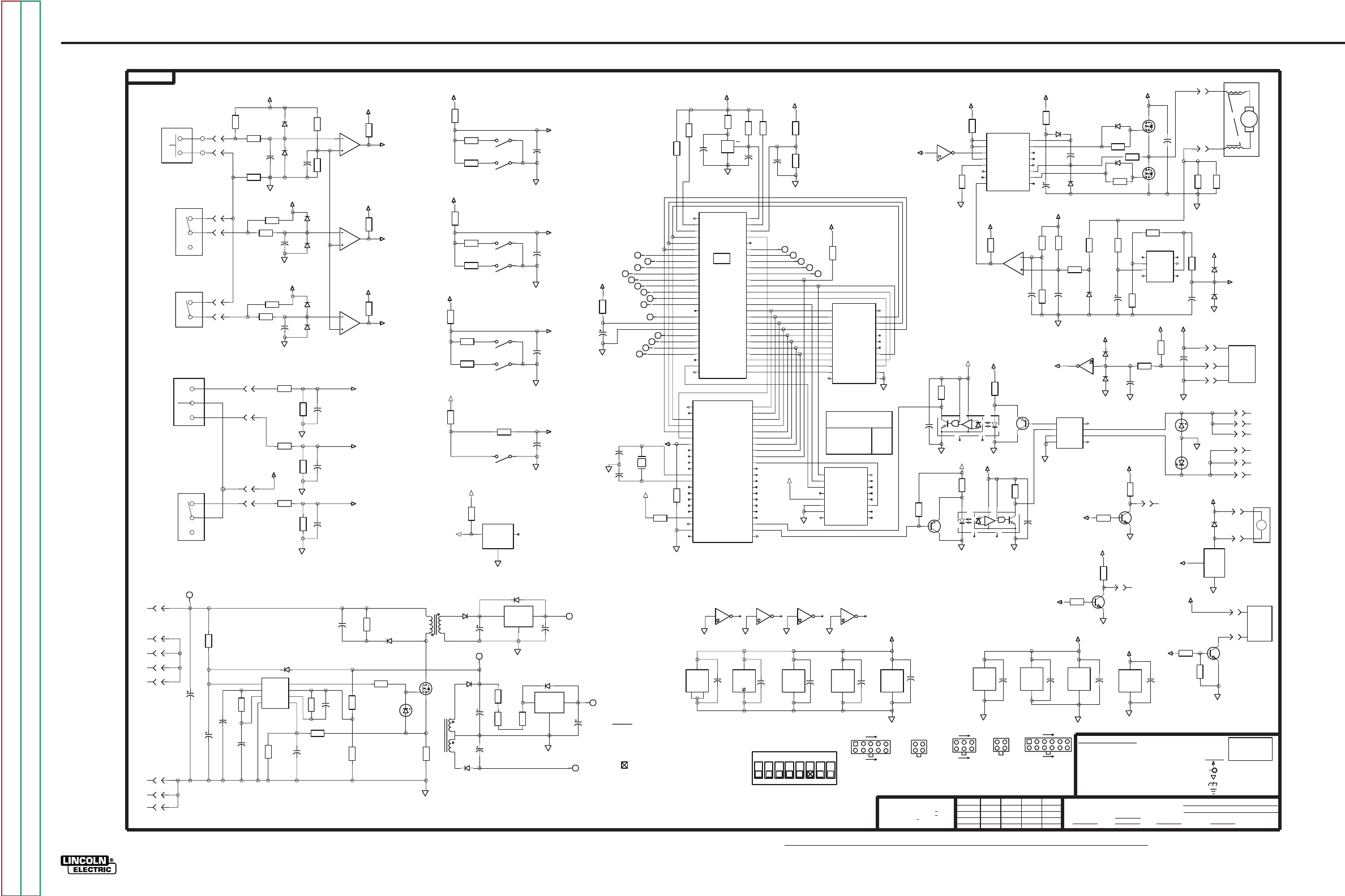
G-19
ELECTRICAL DIAGRAMS
POWER WAVE 455/POWER FEED 10
G-19
Return to Section TOC Return to Section TOC Return to Section TOC Return to Section TOC
Return to Master TOC Return to Master TOC Return to Master TOC Return to Master TOC
POWER FEED 10 CONTROL PC BOARD SCHEMATIC
J5
6
DATA
GND
NC
DS2501
X10
3.32K
R14
J5
3
T1
25t
20t
6
8
7
10.0
R88
332
R74
+40V
GND
GND
J1
9
J2
3
1N4936
D15
GND
+5 VDC
ISOLATED
+12.8 VDC
1.0
1W
R76
50V
.0047
C32
1.8
20V
C37
505
500 500 500
540
500
500
500
+40V
+40V
POWER BUS
FEED
CIRCUIT
+40V
E
F
SWITCHING
+40 VDC
POWER SUPPLY
OFF
HEAD ID
= SWITCH NOT USED
(SEE THE OPERATING NAMUAL FOR ADDITIONAL INFORMATION.)
WITHOUT AFFECTING THE INTERCHANGEABILITY OF A COMPLETE BOARD, THIS DIAGRAM MAY
NOTES :
NUMBER.
NOT SHOW THE EXACT COMPONENTS OR CIRCUITRY OF CONTROLS HAVING A COMMON CODE
N.A. SINCE COMPONENTS OR CIRCUITRY ON A PRINTED CIRCUIT BOARD MAY CHANGE
N.B. A, B, C, POSITIONS ARE FOR THE SETTING OF THE GROUP ID.
THE H POSITION IS FOR SELECTING BETWEEN HIGH & LOW SPEED.
(SWITCHES ARE SHOWN WITH GROUP ID = 0 & LOW MOTOR SPEED.)
2
S1
54
1
3
GROUP ID
HEAD ID
SPARE
6
GROUP ID
HEAD ID
( MSB )
( MSB )
( LSB )
( LSB )
A
50V
0.1
C40
50V
0.1
C44
0
Q6
2N4401
3.32K
R61
0
X68C64
Vcc
X1
Vss
24
12
DIAGNOSTIC
LED #2
J5
10
VCC
485
GND
X8
5
8
50V
0.1
C43
LM2901
X7
3
12
CAN
50V
0.1
C42
1
HIP4082IP
X6
12
6
X
MEM
X
1
20
1
23
P2.3
Vcc
RX1
P1.0
P2.6
P2.7
P2.2
P2.4
AN82527
XTAL1
CLK OUT
AS
TX1
E
READY
MODE0
R/W
XTAL2
/DSACKO
MODE1
Vss2
P2.5
P1.1
/RESET
P2.0
P1.3
AD0
P1.6
AD3
AD1
AD5
AD6
AD7
/INT
/CS
P1.2
AD4
P1.4
P1.5
P2.1
AD2
P1.7
Vss1
TX0
RX0
X21
25
11
10
38
37
9
7
29
44
28
30
6
18
27
5
13
14
12
21
19
4
43
41
42
2
40
3
16
15
31
26
35
39
24
34
17
33
22
32
8
36
74AC138
X2
16
8
X9
89
50V
0.1
C48
Vss1
Vcc
Vss2
AN82527
X21
23
1
20
50V
0.1
C49
X9
2
1
50V
0.1
C39
Vss
Vdd
MC68HC11
X3
1
26
DIAGNOSTIC
LED #1
X9
10
11
OP27
X5
7
4
HEXINV
X9
14
7
4.75K
R94
X9
12
13
4.75K
R95
D
512
500
512
DL2
500
50V
0.1
C38
681
R60
500
-10VDC
PA4
505
500
ISO COM
ISO +5
500
SOLENOID
GAS
DRIVER
A
_
1
5
6
10
J1
J4 J5
DIODES =
CAPACITORS =
1A, 400V
(
MFD
UNLESS OTHERWISE SPECIFIED)
1/4W
UNLESS OTHERWISE SPECIFIED)
GENERAL INFORMATION
ELECTRICAL SYMBOLS PER E1537
.022/50V
RESISTORS = Ohms (
(UNLESS OTHERWISE SPECIFIED)
J3
6
4
1
3
MOLEX CONNECTORS
J2
4
1
2
3
6
7
12
1
4
1
2
3
HIGH SPEED
8
ON HOLES SIZES PER E-2056
POLARITY
ELECTRODE SENSE
ON 3 PLACE DECIMALS IS + .OO2
ON 2 PLACE DECIMALS IS + .O2
ON ALL ANGLES IS + .5 OF A DEGREE
MATERIAL TOLERANCE ("t") TO AGREE
WITH PUBLISHED STANDARDS
Ch'ge.Sht.No.
NONE
DR.
TF
1-8-96
CLEVELAND, OHIO U.S.A.
SCALE
DATE
UNLESS OTHERWISE SPECIFIED TOLERANCE
THE LINCOLN ELECTRIC CO.
7
FILENAME: G3144_1BA
500
500
PD0
505
ID
ISO COM
500
500
3.74K
R27
2200
63V
C29
GND
IN
OUT
X24
50V
0.1
C31
18
15V
C28
4.7
35V
C27
8.25K
R68
10.0
R72
1N4936
D10
332
R73
J1
10
J1
7
18
15V
C36
16t
9
10
G
D
S
18A
200V
Q9
20t
T1
1
5
150K
R69
4.7
35V
C30
4.75K
R92
2.00K
R15
5.11K
R66
26.7
R67
6.19K
R70
1W
16V
DZ3
D11
4.7
35V
C35
50V
2700p
C33
VFB
CS
COMP
RT/CT
VCC
OUT
VREF
GND
X23
2
3
5
1
6
4
8
7
50V
2700p
C34
J1
8
1.50K
R75
GP
ST
505
ISO +5
-10VDC
512
C6
1N4936
D9
C26
J2
4
4.75K
R65
J1
6
10.0
R71
D14
1N4936
D12
J1
1
1N4936
D13
GND
IN
OUT
X22
C5
S1
10
7
3.32K
R12
C11
2.00K
R13
500
ON
4 STEP
J5
5
130
8.0MHz
Y1
100V
22p
C53
2.00K
R11
1.00K
R26
J5
7
3.32K
R10
GAS PURGE
100V
22p
C52
J5
4
ON
J5
9
COLD INCH
C4
505
PD2
500
500
PA4
512
DL1
SD
PD0
ID
DL2
PD3
PA0
-G
OFF
ON
505
B
825
R79
C51
825
R81
S1
12
5
C46
4.75K
R3
6.81K
R5
1.30K
R83
4.75K
R9
S1
15
2
505
2.21K
R2
DIP1
500
505
505
TR
4.75K
R86
825
R90
825
R82
C47
X7
2
4
5
1.30K
R91
S1
98
X7
13
10
11
S1
14
3
DIP3
500
500
DIP2
500
505
505
505
SD
CI
DP
505
-E
-H
A
B
-C
-B
-D
-A
1.30K
R80
S1
16
1
S1
13
4
825
R78
825
R89
X7
1
6
7
1.00K
R25
1W
6.2V
DZ1
3.32K
R96
1W
6.2V
DZ2
4.75K
R51
50V
0.1
C45
J5
8
D8
Q4
70A
60V
D
G
S
Q10
2N4401
50V
0.1
C23
332
R53
681
R58
IN
OUT
GND
X11
SWITCH
3W
0.05
R43
D23
J4
2
J4
3
D22
Q3
70A
60V
D
G
S
V
V
INPUT
CC
EE
NC
OUT
INPUT
NULL
4
NULL
7
OP27
X5
2
8
3
6
5
1
5.62K
R48
540
512
GS
500
500
505
512
500
500
512
ISO COM
15.0K
R55
C22
4.75K
R54
200V
.33
C16
500
512
SUP'S'D'G.
EQUIP.
TYPE
SUBJECT
CHK.
A1FN
_
1
26
MODA
AS
Vss
R/W
Vdd
AD3
A13
A9
A8
AD7
PD1
PD5
PA4
PA5
PA7
VRH
VRL
X3
PA1
PE6
PD4
PE2
PE3
PE4
PE5
AD5
A10
AD4
MC68HC11
PD0
E
AD6
A15
AD2
A14
AD0
A11
A12
AD1
PD2
PA2
/IRQ
PA3
/XIRQ
PE1
EXTAL
XTAL
PE7
MODB
/RESET
PA6
PE0
5
52
27
29
30
51
6
50
49
21
20
23
24
46
47
25
44
33
34
48
40
41
37
42
16
15
11
35
14
12
9
13
39
36
38
10
31
32
19
22
4
45
18
28
3
2
43
8
7
17
D17
C2
D16
D18
C3
D21
D20
D19
1.82K
R22
4.75K
R20
C9
26.7K
R21
1.0
35V
C12
2.21K
R7
1.00K
R6
3.32K
R4
C1
2.21K
R1
2.21K
R84
C50
3.32K
R85
3.32K
R8
10.0K
R52
NCNC
OCI2
5
28
3
6
4
1
7
DL1
500
500
ISO COM
500
GS
505
505
C
CIRCUITRY
C
TACH
CIRCUITRY
A13
DECODE INFO
A14A15
D24
100V
47p
C24
475
R31
1.00K
R30
12
24
A/D0
A/D2
A/D7
R/W
A/D1
A/D4
/WC
A8
A/D3
A/D5
A/D6
A9
GND
N/C
N/C
N/C
SEL
A10
CE
A11
X68C64
AS
E
Vcc
A12
X1
7
21
20
9
15
8
11
17
10
14
13
23
18
22
3
1
4
19
2
16
6
5
X7
14
8
9
C19
Q2
2N4403
500
500
TA
8
16
A
/G2A
B
/Y4
74AC138
/Y5
/Y3
/G2B
C
G1
/Y6
/Y7
/Y2
/Y1
GND
Vcc
/YO
X2
2
3
1
11
6
4
5
15
9
10
13
12
14
7
D6
50V
330p
C20
X9
6
5
4.75K
R44
10.0K
R50
100
R47
13.7K
R45
1.0
35V
C21
2.21K
R46
4.75K
R24
10.0K
R35
10.0K
R40
1N4936
D1
6
12
BLO
ALI
AHI
AHB
BHB
ALO
AHO
Vss
AHS
BHS
Vdd
BHI
BHO
BLI
DIS
DEL
HIP4082IP
X6
8
10
11
15
14
13
16
9
5
4
3
7
2
1
1.0
35V
C18
1N4936
D2
15.0
R39
4A
200V
D4
150
R41
1N4936
D3
50V
0.1
C17 100
R37
100
R36
D25
505
MO
Q1
2N4403
50V
0.1
C14
8
5
485
DE
GND/RE
A
VCC
B
DI
RO
X8
2
7
4
3
1
6
500
ISO +5
505
505
1.00K
R49
50V
0.1
C15
Q5
2N4401
10.0K
R77
3.32K
R59
X9
4
3
475
R33
1.00K
R34
NC NC
OCI1
5
2
8
3
6
4
1
7
ISO +5
ISO COM
505
500
ISO COM
3144
512
S-8054HN
Vdd
Vss
RES
X20
J5
1
1.00K
R19
J5
11
J5
12
505
10K
R87
512
10K
R17
J5
2
505
512
500
540
DP
GP
MO
TA
PD2
CU
500
500
CI
DIP2
DIP1
DIP3
ST
TR
500
512
DUAL PROC.
B
ON
TRIGGER
OFF
G
M
A
SHUT DOWN
540
J3
4
C8
uCOMPUTER
2.21K
R18
50V
0.1
C7
MOTOR
J1
5
J6
2
J6
1
J1
4
J1
2
J2
2
J2
1
J1
3
97
J3
6
J3
3
CU
Q- 10
D-
53
25
3144
SHT.
POWER SUPPLY SOURCE POINT
CONTROL P.C. BOARD SCHEMATIC
LABELS
COMMON CONNECTION
FRAME CONNECTION
VOLTAGE NET
LAST NO. USED
G
WIRE FEEDER
NO.
EARTH GROUND CONNECTION
C-
R-
X- 24
DZ- 3
Y- 1
S- 1
OCI- 2
T- 1
SUPPLY
SOLENOID
VOLTAGE
LEAD
SENSE
DATA BUS
TACH.
BUS L
BUS H
GAS
BUS H
BLUE
BLACK
RED
J3
1
3W
0.05
R42
J4
1
500
100K
R97
BUS L
CONTROL
BUS L
BUS H
BS
10-17-97A
XB
NOTE: Lincoln Electric assumes no responsibility for liablilities resulting from board level troubleshooting. PC Board repairs will invalidate your factory warranty. Individual Printed Circuit Board Components are not available from Lincoln Electric. This information is pro-
vided for reference only. Lincoln Electric discourages board level troubleshooting and repair since it may compromise the quality of the design and may result in danger to the Machine Operator or Technician. Improper PC board repairs could result in damage to the
machine.
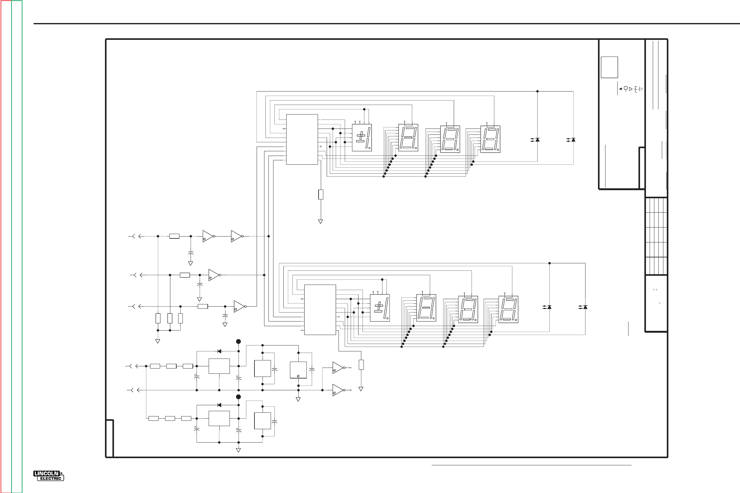
G-20
ELECTRICAL DIAGRAMS
POWER WAVE 455/POWER FEED 10
G-20
Return to Section TOC Return to Section TOC Return to Section TOC Return to Section TOC
Return to Master TOC Return to Master TOC Return to Master TOC Return to Master TOC
POWER FEED 10 DISPLAY PC BOARD SCHEMATIC
LED- 4
FILENAME: L10276_1AB
LED2
LED1
14
3
Rx
Vdd
d
BANK1
g
DATA OUT
f
CLOCK
MC14489
DATA IN
h
Vss
BANK3
BANK4
BANK2
a
/ENABLE
e
c
BANK5
b
X3
18
9
17
6
5
2
10
19
8
1
13
12
16
20
11
15
4
7
D
A
C
B
DP
DISP4
4 7
1
5
3
2
6
9
8
DISP2
2
1
4
9
5
10
7
6
8
3
AMPS
WFS
D-
DIODES =
2
DISP- 8
R-
SUPPLY
GENERAL INFORMATION
ELECTRICAL SYMBOLS PER E1537
C-
LABELS
LAST NO. USED
POWER SUPPLY SOURCE POINT
X- 5
14
1/4W
UNLESS OTHERWISE SPECIFIED)
(UNLESS OTHERWISE SPECIFIED)
UNLESS OTHERWISE SPECIFIED)
COMMON CONNECTION
.022/50V
FRAME CONNECTION
1A, 400V
(
MFD
CAPACITORS =
RESISTORS = Ohms (
VOLTAGE NET
10
DR.
DATE
SUP'S'D'G.
2/5/96
SHT.
SCALE
10276
THE LINCOLN ELECTRIC CO.
TYPE
NO.
L
EQUIP.
SUBJECT
NONE
CLEVELAND, OHIO U.S.A.
EARTH GROUND CONNECTION
CTT
CHK.
DISP3
2
1
4
9
5
10
7
6
8
3
DISP1
2
1
4
9
5
10
7
6
8
3
500
500
475
R9
J1
5
X5
10
11
10K
R5
10.0
R4
GND
IN
OUT
X2
D1
J1
8
10.0
R13
MC14489
Vss
Vdd
X4
3
14
J1
6
4.7
35V
C5
MC14489
Vss
Vdd
X3
3
14
18
15V
C6
4.7
35V
C1
10.0
R2
18
15V
C2
GND
IN
OUT
X1
10.0
R3
50V
.0047
C9
1
2
J1
7
D2
50V
.0047
C8
1
2
10.0
R14
10.0
R1
475
R8
50V
.0047
C7
1
2
LATCH
X5
89
10K
R6
10K
R7
475
R10
J1
4
X5
2
1
+5VB
500
+5VA
500
500
500
10276
512
L
SCK
7805
7805
MOSI
X5
12
13
VOLTS
HEXINV
X5
14
7
LED3
DISP6
2
1
4
9
5
10
7
6
8
3
DISP5
2
1
4
9
5
10
7
6
8
3
TRIM
DISP7
2
1
4
9
5
10
7
6
8
3
50V
0.1
C3
D
A
C
B
DP
DISP8
4 7
1
5
3
2
6
9
8
500
LED4
50V
0.1
C4 X5
6
5
X5
4
3
NOT SHOW THE EXACT COMPONENTS OR CIRCUITRY OF CONTROLS HAVING A COMMON CODE
WITHOUT AFFECTING THE INTERCHANGEABILITY OF A COMPLETE BOARD, THIS DIAGRAM MAY
N.A. SINCE COMPONENTS OR CIRCUITRY ON A PRINTED CIRCUIT BOARD MAY CHANGE
NUMBER.
UNLESS OTHERWISE SPECIFIED TOLERANCE
ON HOLES SIZES PER E-2056
NOTES :
Ch'ge.Sht.No.
WITH PUBLISHED STANDARDS
ON 2 PLACE DECIMALS IS + .O2
MATERIAL TOLERANCE ("t") TO AGREE
ON ALL ANGLES IS + .5 OF A DEGREE
ON 3 PLACE DECIMALS IS + .OO2
1.50K
R12
50V
0.1
C10
1.50K
R11
500
500
14
3
Rx
Vdd
d
BANK1
g
DATA OUT
f
/ENABLE
MC14489
DATA IN
h
Vss
BANK3
BANK4
BANK2
a
CLOCK
e
c
BANK5
b
X4
18
9
17
6
5
2
11
19
8
1
13
12
16
20
10
15
4
7
SCHEMATIC, STANDARD DISPLAY PCB
XA
POWER DRIVE WIRE FEEDER
BS
10-17-97A
NOTE: Lincoln Electric assumes no responsibility for liablilities resulting from board level troubleshooting. PC Board repairs will invalidate your factory warranty. Individual Printed Circuit Board Components are not available from Lincoln Electric. This information is pro-
vided for reference only. Lincoln Electric discourages board level troubleshooting and repair since it may compromise the quality of the design and may result in danger to the Machine Operator or Technician. Improper PC board repairs could result in damage to the
machine.
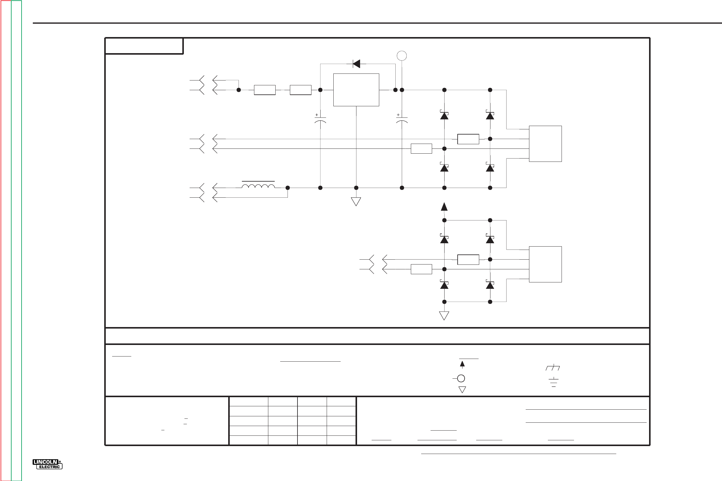
G-21
ELECTRICAL DIAGRAMS
POWER WAVE 455/POWER FEED 10
G-21
Return to Section TOC Return to Section TOC Return to Section TOC Return to Section TOC
Return to Master TOC Return to Master TOC Return to Master TOC Return to Master TOC
POWER FEED 10 ENCODER PC BOARD SCHEMATIC
+5VDC
22920
D3
D9
J1
5
10.0
R5
J1
6
J1
1
J1
8
18
15V
C2
475
R2
J1
7
J1
2
X
A2
+
Y
-
2
1
4
3
475
R4
J1
3
D8
D6
475
R3
D5
D7
J1
4
X
A1
+
Y
-
OPTICAL
2
1
4
3
475
R1
4.7
35V
C1
D2
D1
10.0
R6
GND
IN
OUT
X1
D4
+5VDC
Ch'ge.Sht.No.
UNLESS OTHERWISE SPECIFIED TOLERANCE
.022/50V
DIODES =
CAPACITORS =
COMMON CONNECTION
RESISTORS = Ohms (
MFD
LABELS
THE LINCOLN ELECTRIC CO.
THE LINCOLN ELECTRIC CO.
SUPPLY
1A, 400V
ENCODER
S
ROTARY
ROTARY
ENCODER
OPTICAL
.33mH
L1
MATERIAL TOLERANCE ("t") TO AGREE
SUBJECT
SCALE
22920
JRF
EQUIP.
SHT.
NOTES :
MAY CHANGE
THE INTERCHANGEABILITY
SINCE COMPONENTS OR CIRCUITRY ON
THIS SHEET CONTAINS PROPRIETARY INFORMATION OWNED BY
WITHOUT AFFECTING
CODE NUMBER.
ON HOLES SIZES PER E-2056
S
ELECTRICAL SYMBOLS PER E1537
GENERAL INFORMATION
A PRINTED
N.A.
OR CIRCUITRY OF
ON 3 PLACE DECIMALS IS + .OO2
CONTROLS HAVING A COMMON
BOARD.
OF A COMPLETE
3-11-96
USER INTERFACE
DUAL ENCDR PCB SCHEM.
NO.
(UNLESS OTHERWISE SPECIFIED)
DR.
CLEVELAND, OHIO U.S.A.
DATE
1/4W
THE LINCOLN ELECTRIC CO.
THIS DIAGRAM MAY NOT
CIRCUIT BOARD
VOLTAGE NET
FRAME CONNECTION
AND IS NOT TO BE REPRODUCED, DISCLOSED OR USED WITHOUT THE EXPRESS PERMISSION OF
EARTH GROUND CONNECTION
CHK.
SUP'S'D'G.
POWER SUPPLY SOURCE POINT
ON 2 PLACE DECIMALS IS + .O2
UNLESS OTHERWISE SPECIFIED)
TYPE
UNLESS OTHERWISE SPECIFIED)
FILENAME: S22920_2BB
NONE
(
WITH PUBLISHED STANDARDS
SHOW THE EXACT COMPONENTS
ON ALL ANGLES IS + .5 OF A DEGREE
XA
10-17-97
3-27-98D
NOTE: Lincoln Electric assumes no responsibility for liablilities resulting from board level troubleshooting. PC Board repairs will invalidate your factory warranty. Individual Printed Circuit Board Components are not available from Lincoln Electric. This information is pro-
vided for reference only. Lincoln Electric discourages board level troubleshooting and repair since it may compromise the quality of the design and may result in danger to the Machine Operator or Technician. Improper PC board repairs could result in damage to the
machine.
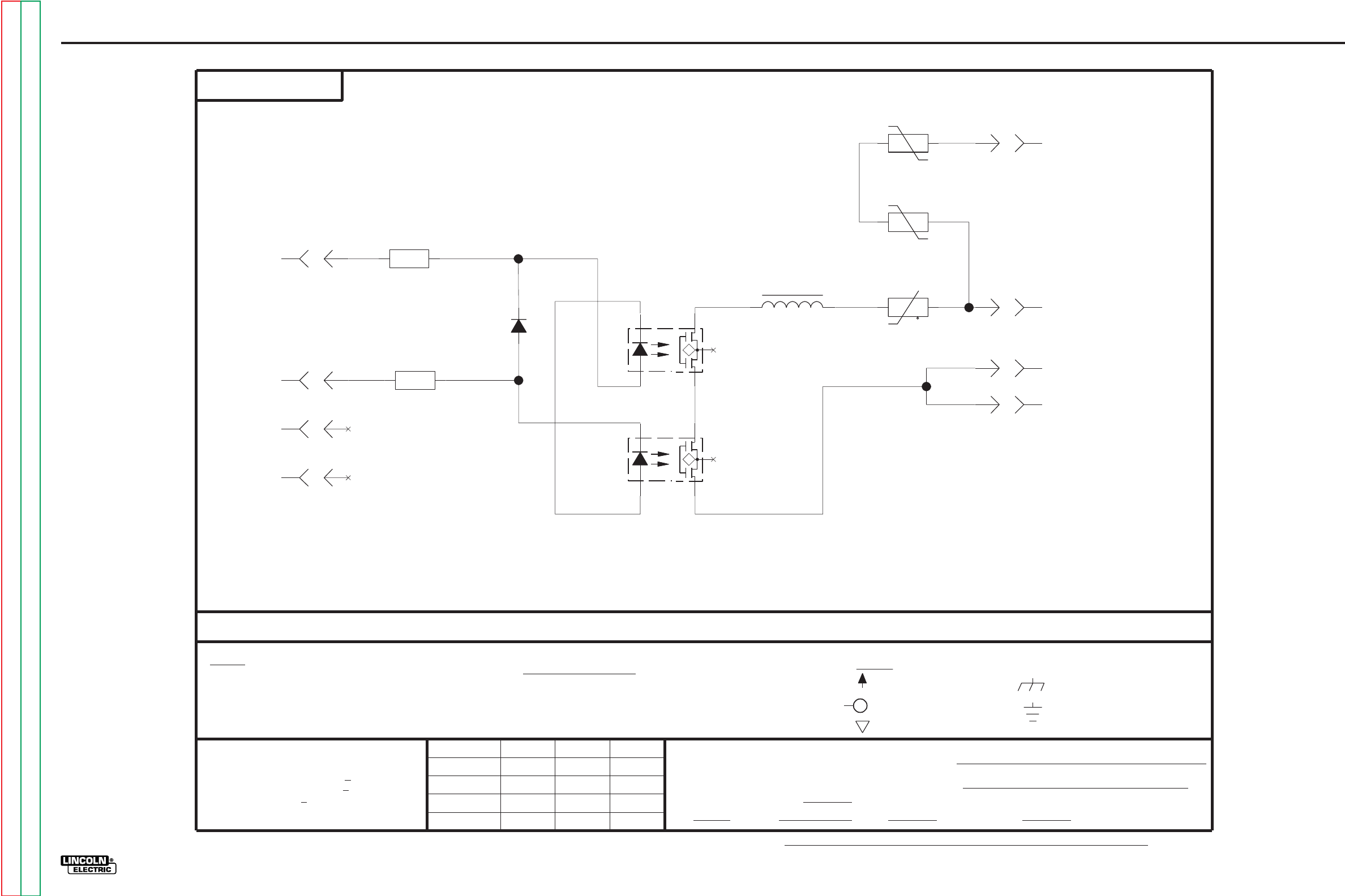
G-22
ELECTRICAL DIAGRAMS
POWER WAVE 455/POWER FEED 10
G-22
Return to Section TOC Return to Section TOC Return to Section TOC Return to Section TOC
Return to Master TOC Return to Master TOC Return to Master TOC Return to Master TOC
POWER FEED 10 VOLTAGE SENSE PC BOARD SCHEMATIC
EARTH GROUND CONNECTION
S
OCI2
1
4
6
2
5
160J
320V
TP1
475
R2
.33mH
L1
J2
1
+
t
56
R3
J1
5
J1
2
J2
2
475
R1
J1
6
J1
1
160J
320V
TP2
D1
S
OCI1
1
4
6
2
5
J1
3
6/9/98
FILENAME: S23918_3CA
MAB
COMMON CONNECTION
THE LINCOLN ELECTRIC CO.
23918
#67 LEAD NETWORK
LABELS
1A, 400V
SHOW THE EXACT COMPONENTS
THE INTERCHANGEABILITY
WITHOUT AFFECTING
CIRCUIT BOARD
MAY CHANGE
THE LINCOLN ELECTRIC CO.
SINCE COMPONENTS OR CIRCUITRY ON
BOARD.
ON ALL ANGLES IS + .5 OF A DEGREE
SHT.
CODE NUMBER.
CONTROLS HAVING A COMMON
(
MATERIAL TOLERANCE ("t") TO AGREE
OF A COMPLETE
N.A.
ON HOLES SIZES PER E-2056
UNLESS OTHERWISE SPECIFIED)
THIS SHEET CONTAINS PROPRIETARY INFORMATION OWNED BY
THE LINCOLN ELECTRIC CO.
AND IS NOT TO BE REPRODUCED, DISCLOSED OR USED WITHOUT THE EXPRESS PERMISSION OF
UNLESS OTHERWISE SPECIFIED)
S
WITH PUBLISHED STANDARDS
TO HEAD P.C.B.
ELECTRICAL SYMBOLS PER E1537
DIODES =
FRAME
BRASS BLOCK
NOTES :
MFD
.022/50V
CAPACITORS =
1/4W
VOLTAGE NET
GENERAL INFORMATION
A PRINTED
THIS DIAGRAM MAY NOT
RESISTORS = Ohms (
(UNLESS OTHERWISE SPECIFIED)
UNLESS OTHERWISE SPECIFIED TOLERANCE
CLEVELAND, OHIO U.S.A.
FRAME CONNECTION
ON 3 PLACE DECIMALS IS + .OO2
Ch'ge.Sht.No.
OR CIRCUITRY OF
DR.
ON 2 PLACE DECIMALS IS + .O2
23918
NONE
SUPPLY
SCALE
SUP'S'D'G.
POWER SUPPLY SOURCE POINT
DATE
S
NO.
SUBJECT
SWG VOLTAGE SENSE SELECT
SCHEMATIC
TYPE
EQUIP.
CHK.
J1
4
XA
10-17-97
10-9-98D
NOTE: Lincoln Electric assumes no responsibility for liablilities resulting from board level troubleshooting. PC Board repairs will invalidate your factory warranty. Individual Printed Circuit Board Components are not available from Lincoln Electric. This information is pro-
vided for reference only. Lincoln Electric discourages board level troubleshooting and repair since it may compromise the quality of the design and may result in danger to the Machine Operator or Technician. Improper PC board repairs could result in damage to the
machine.
