Lincoln Electric Precision Tig 275 Svm162 B Users Manual
SVM162-B to the manual 529549b3-5f23-45da-a4b6-f63aa8c2e1a5
2015-02-09
: Lincoln-Electric Lincoln-Electric-Precision-Tig-275-Svm162-B-Users-Manual-574601 lincoln-electric-precision-tig-275-svm162-b-users-manual-574601 lincoln-electric pdf
Open the PDF directly: View PDF ![]() .
.
Page Count: 140 [warning: Documents this large are best viewed by clicking the View PDF Link!]
- Master Table of Content
- Safety
- Section A - Installation
- Section B - Operation
- Section C - Accessories
- Section D - Maintenance
- Section E - Theory of Operation
- Section F - Troubleshooting and Repair
- Symptoms
- The machine is dead. No weld output – no 115 VAC at the receptacle.
- No welding output. The 115 VAC is present at the receptacle.
- No output from the machine in either Stick or TIG modes. The thermal light is on.
- The machine does not respond (no gas flow, no high frequency and no open circuit voltage) when the arc start switch or Amptrol is activated. The thermal light is not lit.
- The machine does not have welding output in the Stick mode. The machine operates correctly in the TIG mode.
- The machine has welding output in the Stick mode but no output in the TIG mode. ( no gas flow or high frequency).
- The machine welds at a very low output regardless of the current control setting.
- The machine welds at a very high output regardless of the current control setting.
- Accessories plugged into the volt receptacle do not work.
- The machine makes a very loud buzzing noise in DC Stick or in DC TIG modes. There is no current draw from the machine’s output terminals. (The machine is not externally loaded).
- The machine output is intermittently lost. Gas flow and high frequency are also interrupted.
- No gas or water flow (with optional water solenoid) when the arc start switch or Amptrol is activated in the TIG mode. All other machine functions are normal.
- No high frequency. The machine is in the TIG mode and has normal output.
- The High frequency is on continuously in DC TIG or shuts off in AC TIG.
- High frequency “spark” is present but weak.
- Poor arc starting in the DC TIG mode.
- The high frequency “spark” is present at the tungsten electrode, but the operator is unable to establish a welding arc. The machine has a normal open circuit voltage. Refer to Technical Specifications in the Installation section.
- When AC TIG welding, the arc is erratic and there is a loss of “cleaning” of the work piece.
- Arc “pulsates” in AC polarity. DC TIG is OK.
- The stick electrode “blasts-off” when touched to the work piece.
- Variable or sluggish welding arc when welding in the Stick mode.
- The meter does not display V (volt) or minimum current.
- The AC wave balance control does not function properly.
- Gas pre-flow and post-flow time is too long.
- The meter does not display V (volt) or minimum current.
- The meter does not light up. Other machine functions are OK.
- Section G - Electrical Diagrams

PRECISION TIG 275
SERVICE MANUAL
SVM162-B
January, 2008
Safety Depends on You
Lincoln arc welding and cutting
equipment is designed and built
with safety in mind. However, your
overall safety can be increased by
proper installation ... and thoughtful
operation on your part. DO NOT
INSTALL, OPERATE OR REPAIR
THIS EQUIPMENT WITHOUT
READING THIS MANUAL AND
THE SAFETY PRECAUTIONS
CONTAINED THROUGHOUT.
And, most importantly, think before
you act and be careful.
For use with machines having Code Numbers: 10806; 10807; 10893; 11158; 11159
• Sales and Service through Subsidiaries and Distributors Worldwide •
Cleveland, Ohio 44117-1199 U.S.A. TEL: 888-935-3877 FAX: 216.486.1751 WEB SITE: www.lincolnelectric.com
• World's Leader in Welding and Cutting Products •
Copyright © Lincoln Global Inc.
Return to Master TOC Return to Master TOC Return to Master TOC Return to Master TOC
View Safety Info View Safety Info View Safety Info View Safety Info
RETURN TO MAIN MENU
SAFETY
iiii
Return to Master TOC Return to Master TOC Return to Master TOC Return to Master TOC
FOR ENGINE
powered equipment.
1.a. Turn the engine off before troubleshooting and maintenance
work unless the maintenance work requires it to be running.
____________________________________________________
1.b.Operate engines in open, well-ventilated
areas or vent the engine exhaust fumes
outdoors.
____________________________________________________
1.c. Do not add the fuel near an open flame weld-
ing arc or when the engine is running. Stop
the engine and allow it to cool before refuel-
ing to prevent spilled fuel from vaporizing on
contact with hot engine parts and igniting. Do
not spill fuel when filling tank. If fuel is spilled,
wipe it up and do not start engine until fumes
have been eliminated.
____________________________________________________
1.d. Keep all equipment safety guards, covers and devices in posi-
tion and in good repair.Keep hands, hair, clothing and tools
away from V-belts, gears, fans and all other moving parts
when starting, operating or repairing equipment.
____________________________________________________
1.e. In some cases it may be necessary to remove safety
guards to perform required maintenance. Remove
guards only when necessary and replace them when the
maintenance requiring their removal is complete.
Always use the greatest care when working near moving
parts.
___________________________________________________
1.f. Do not put your hands near the engine fan.
Do not attempt to override the governor or
idler by pushing on the throttle control rods
while the engine is running.
___________________________________________________
1.g. To prevent accidentally starting gasoline engines while
turning the engine or welding generator during maintenance
work, disconnect the spark plug wires, distributor cap or
magneto wire as appropriate.
ARC WELDING can be hazardous. PROTECT YOURSELF AND OTHERS FROM POSSIBLE SERIOUS INJURY OR DEATH.
KEEP CHILDREN AWAY. PACEMAKER WEARERS SHOULD CONSULT WITH THEIR DOCTOR BEFORE OPERATING.
Read and understand the following safety highlights. For additional safety information, it is strongly recommended that you
purchase a copy of “Safety in Welding & Cutting - ANSI Standard Z49.1” from the American Welding Society, P.O. Box 351040,
Miami, Florida 33135 or CSA Standard W117.2-1974. A Free copy of “Arc Welding Safety” booklet E205 is available from the
Lincoln Electric Company, 22801 St. Clair Avenue, Cleveland, Ohio 44117-1199.
BE SURE THAT ALL INSTALLATION, OPERATION, MAINTENANCE AND REPAIR PROCEDURES ARE
PERFORMED ONLY BY QUALIFIED INDIVIDUALS.
WARNING
Mar ʻ95
ELECTRIC AND
MAGNETIC FIELDS
may be dangerous
2.a. Electric current flowing through any conductor causes
localized Electric and Magnetic Fields (EMF). Welding
current creates EMF fields around welding cables and
welding machines
2.b. EMF fields may interfere with some pacemakers, and
welders having a pacemaker should consult their physician
before welding.
2.c. Exposure to EMF fields in welding may have other health
effects which are now not known.
2.d. All welders should use the following procedures in order to
minimize exposure to EMF fields from the welding circuit:
2.d.1.
Route the electrode and work cables together - Secure
them with tape when possible.
2.d.2. Never coil the electrode lead around your body.
2.d.3. Do not place your body between the electrode and
work cables. If the electrode cable is on your right
side, the work cable should also be on your right side.
2.d.4. Connect the work cable to the workpiece as close as
possible to the area being welded.
2.d.5. Do not work next to welding power source.
1.h. To avoid scalding, do not remove the
radiator pressure cap when the engine is
hot.
CALIFORNIA PROPOSITION 65 WARNINGS
Diesel engine exhaust and some of its constituents
are known to the State of California to cause can-
cer, birth defects, and other reproductive harm.
The engine exhaust from this product contains
chemicals known to the State of California to cause
cancer, birth defects, or other reproductive harm.
The Above For Diesel Engines The Above For Gasoline Engines
SAFETY
iiiiiiii
Return to Master TOC Return to Master TOC Return to Master TOC Return to Master TOC
FUMES AND GASES
can be dangerous.
5.a. Welding may produce fumes and gases
hazardous to health. Avoid breathing these
fumes and gases.When welding, keep
your head out of the fume. Use enough
ventilation and/or exhaust at the arc to keep
fumes and gases away from the breathing zone. When
welding with electrodes which require special
ventilation such as stainless or hard facing (see
instructions on container or MSDS) or on lead or
cadmium plated steel and other metals or coatings
which produce highly toxic fumes, keep exposure as
low as possible and below Threshold Limit Values (TLV)
using local exhaust or mechanical ventilation. In
confined spaces or in some circumstances, outdoors, a
respirator may be required. Additional precautions are
also required when welding on galvanized steel.
5. b. The operation of welding fume control equipment is affected
by various factors including proper use and positioning of the
equipment, maintenance of the equipment and the specific
welding procedure and application involved. Worker expo-
sure level should be checked upon installation and periodi-
cally thereafter to be certain it is within applicable OSHA PEL
and ACGIH TLV limits.
5.c.
Do not weld in locations near chlorinated hydrocarbon
vapors
coming from degreasing, cleaning or spraying operations.
The heat and rays of the arc can react with solvent vapors
to
form phosgene, a highly toxic gas, and other irritating prod-
ucts.
5.d. Shielding gases used for arc welding can displace air and
cause injury or death. Always use enough ventilation,
especially in confined areas, to insure breathing air is safe.
5.e. Read and understand the manufacturerʼs instructions for this
equipment and the consumables to be used, including the
material safety data sheet (MSDS) and follow your
employerʼs safety practices. MSDS forms are available from
your welding distributor or from the manufacturer.
5.f. Also see item 1.b.
ARC RAYS can burn.
4.a. Use a shield with the proper filter and cover
plates to protect your eyes from sparks and
the rays of the arc when welding or observing
open arc welding. Headshield and filter lens
should conform to ANSI Z87. I standards.
4.b. Use suitable clothing made from durable flame-resistant
material to protect your skin and that of your helpers from
the arc rays.
4.c. Protect other nearby personnel with suitable, non-flammable
screening and/or warn them not to watch the arc nor expose
themselves to the arc rays or to hot spatter or metal.
ELECTRIC SHOCK can kill.
3.a. The electrode and work (or ground) circuits
are electrically “hot” when the welder is on.
Do not touch these “hot” parts with your bare
skin or wet clothing. Wear dry, hole-free
gloves to insulate hands.
3.b. Insulate yourself from work and ground using dry insulation.
Make certain the insulation is large enough to cover your full
area of physical contact with work and ground.
In addition to the normal safety precautions, if welding
must be performed under electrically hazardous
conditions (in damp locations or while wearing wet
clothing; on metal structures such as floors, gratings or
scaffolds; when in cramped positions such as sitting,
kneeling or lying, if there is a high risk of unavoidable or
accidental contact with the workpiece or ground) use
the following equipment:
• Semiautomatic DC Constant Voltage (Wire) Welder.
• DC Manual (Stick) Welder.
• AC Welder with Reduced Voltage Control.
3.c. In semiautomatic or automatic wire welding, the electrode,
electrode reel, welding head, nozzle or semiautomatic
welding gun are also electrically “hot”.
3.d. Always be sure the work cable makes a good electrical
connection with the metal being welded. The connection
should be as close as possible to the area being welded.
3.e. Ground the work or metal to be welded to a good electrical
(earth) ground.
3.f.
Maintain the electrode holder, work clamp, welding cable and
welding machine in good, safe operating condition. Replace
damaged insulation.
3.g. Never dip the electrode in water for cooling.
3.h. Never simultaneously touch electrically “hot” parts of
electrode holders connected to two welders because voltage
between the two can be the total of the open circuit voltage
of both welders.
3.i. When working above floor level, use a safety belt to protect
yourself from a fall should you get a shock.
3.j. Also see Items 6.c. and 8.
Aug ʻ06
SSAAFFEETTYY
iiiiiiiiiiii
Return to Master TOC Return to Master TOC Return to Master TOC Return to Master TOC
Mar ʻ95
FOR ELECTRICALLY
powered equipment.
8.a. Turn off input power using the disconnect
switch at the fuse box before working on
the equipment.
8.b. Install equipment in accordance with the U.S. National
Electrical Code, all local codes and the manufacturerʼs
recommendations.
8.c. Ground the equipment in accordance with the U.S. National
Electrical Code and the manufacturerʼs recommendations.
CYLINDER may explode
if damaged.
7.a. Use only compressed gas cylinders
containing the correct shielding gas for the
process used and properly operating
regulators designed for the gas and
pressure used. All hoses, fittings, etc. should be suitable for
the application and maintained in good condition.
7.b. Always keep cylinders in an upright position securely
chained to an undercarriage or fixed support.
7.c. Cylinders should be located:
• Away from areas where they may be struck or subjected to
physical damage.
• A safe distance from arc welding or cutting operations and
any other source of heat, sparks, or flame.
7.d. Never allow the electrode, electrode holder or any other
electrically “hot” parts to touch a cylinder.
7.e. Keep your head and face away from the cylinder valve outlet
when opening the cylinder valve.
7.f. Valve protection caps should always be in place and hand
tight except when the cylinder is in use or connected for
use.
7.g. Read and follow the instructions on compressed gas
cylinders, associated equipment, and CGA publication P-l,
“Precautions for Safe Handling of Compressed Gases in
Cylinders,” available from the Compressed Gas Association
1235 Jefferson Davis Highway, Arlington, VA 22202.
WELDING SPARKS can
cause fire or explosion.
6.a.
Remove fire hazards from the welding area.
If this is not possible, cover them to prevent
the welding sparks from starting a fire.
Remember that welding sparks and hot
materials from welding can easily go through small cracks
and openings to adjacent areas. Avoid welding near
hydraulic lines. Have a fire extinguisher readily available.
6.b. Where compressed gases are to be used at the job site,
special precautions should be used to prevent hazardous
situations. Refer to “Safety in Welding and Cutting” (ANSI
Standard Z49.1) and the operating information for the
equipment being used.
6.c. When not welding, make certain no part of the electrode
circuit is touching the work or ground. Accidental contact can
cause overheating and create a fire hazard.
6.d. Do not heat, cut or weld tanks, drums or containers until the
proper steps have been taken to insure that such procedures
will not cause flammable or toxic vapors from substances
inside. They can cause an explosion even
though
they have
been “cleaned”. For information, purchase “Recommended
Safe Practices for the
Preparation
for Welding and Cutting of
Containers and Piping That Have Held Hazardous
Substances”, AWS F4.1 from the American Welding Society
(see address above).
6.e. Vent hollow castings or containers before heating, cutting or
welding. They may explode.
6.f.
Sparks and spatter are thrown from the welding arc. Wear oil
free protective garments such as leather gloves, heavy shirt,
cuffless trousers, high shoes and a cap over your hair. Wear
ear plugs when welding out of position or in confined places.
Always wear safety glasses with side shields when in a
welding area.
6.g. Connect the work cable to the work as close to the welding
area as practical. Work cables connected to the building
framework or other locations away from the welding area
increase the possibility of the welding current passing
through lifting chains, crane cables or other alternate circuits.
This can create fire hazards or overheat lifting chains or
cables until they fail.
6.h. Also see item 1.c.

SSAAFFEETTYY
iivviivv
Return to Master TOC Return to Master TOC Return to Master TOC Return to Master TOC
Mar ʻ93
PRÉCAUTIONS DE SÛRETÉ
Pour votre propre protection lire et observer toutes les instructions
et les précautions de sûreté specifiques qui parraissent dans ce
manuel aussi bien que les précautions de sûreté générales suiv-
antes:
Sûreté Pour Soudage A L’Arc
1. Protegez-vous contre la secousse électrique:
a. Les circuits à lʼélectrode et à la piéce sont sous tension
quand la machine à souder est en marche. Eviter toujours
tout contact entre les parties sous tension et la peau nue
ou les vétements mouillés. Porter des gants secs et sans
trous pour isoler les mains.
b. Faire trés attention de bien sʼisoler de la masse quand on
soude dans des endroits humides, ou sur un plancher met-
allique ou des grilles metalliques, principalement dans
les positions assis ou couché pour lesquelles une grande
partie du corps peut être en contact avec la masse.
c. Maintenir le porte-électrode, la pince de masse, le câble de
soudage et la machine à souder en bon et sûr état defonc-
tionnement.
d.Ne jamais plonger le porte-électrode dans lʼeau pour le
refroidir.
e. Ne jamais toucher simultanément les parties sous tension
des porte-électrodes connectés à deux machines à souder
parce que la tension entre les deux pinces peut être le total
de la tension à vide des deux machines.
f. Si on utilise la machine à souder comme une source de
courant pour soudage semi-automatique, ces precautions
pour le porte-électrode sʼapplicuent aussi au pistolet de
soudage.
2. Dans le cas de travail au dessus du niveau du sol, se protéger
contre les chutes dans le cas ou on recoit un choc. Ne jamais
enrouler le câble-électrode autour de nʼimporte quelle partie du
corps.
3. Un coup dʼarc peut être plus sévère quʼun coup de soliel, donc:
a. Utiliser un bon masque avec un verre filtrant approprié ainsi
quʼun verre blanc afin de se protéger les yeux du rayon-
nement de lʼarc et des projections quand on soude ou
quand on regarde lʼarc.
b. Porter des vêtements convenables afin de protéger la peau
de soudeur et des aides contre le rayonnement de lʻarc.
c. Protéger lʼautre personnel travaillant à proximité au
soudage à lʼaide dʼécrans appropriés et non-inflammables.
4. Des gouttes de laitier en fusion sont émises de lʼarc de
soudage. Se protéger avec des vêtements de protection libres
de lʼhuile, tels que les gants en cuir, chemise épaisse, pan-
talons sans revers, et chaussures montantes.
5. Toujours porter des lunettes de sécurité dans la zone de
soudage. Utiliser des lunettes avec écrans lateraux dans les
zones où lʼon pique le laitier.
6. Eloigner les matériaux inflammables ou les recouvrir afin de
prévenir tout risque dʼincendie dû aux étincelles.
7. Quand on ne soude pas, poser la pince à une endroit isolé de
la masse. Un court-circuit accidental peut provoquer un
échauffement et un risque dʼincendie.
8. Sʼassurer que la masse est connectée le plus prés possible de
la zone de travail quʼil est pratique de le faire. Si on place la
masse sur la charpente de la construction ou dʼautres endroits
éloignés de la zone de travail, on augmente le risque de voir
passer le courant de soudage par les chaines de levage,
câbles de grue, ou autres circuits. Cela peut provoquer des
risques dʼincendie ou dʼechauffement des chaines et des
câbles jusquʼà ce quʼils se rompent.
9. Assurer une ventilation suffisante dans la zone de soudage.
Ceci est particuliérement important pour le soudage de tôles
galvanisées plombées, ou cadmiées ou tout autre métal qui
produit des fumeés toxiques.
10. Ne pas souder en présence de vapeurs de chlore provenant
dʼopérations de dégraissage, nettoyage ou pistolage. La
chaleur ou les rayons de lʼarc peuvent réagir avec les vapeurs
du solvant pour produire du phosgéne (gas fortement toxique)
ou autres produits irritants.
11. Pour obtenir de plus amples renseignements sur la sûreté, voir
le code “Code for safety in welding and cutting” CSA Standard
W 117.2-1974.
PRÉCAUTIONS DE SÛRETÉ POUR
LES MACHINES À SOUDER À
TRANSFORMATEUR ET À
REDRESSEUR
1. Relier à la terre le chassis du poste conformement au code de
lʼélectricité et aux recommendations du fabricant. Le dispositif
de montage ou la piece à souder doit être branché à une
bonne mise à la terre.
2. Autant que possible, Iʼinstallation et lʼentretien du poste seront
effectués par un électricien qualifié.
3. Avant de faires des travaux à lʼinterieur de poste, la debranch-
er à lʼinterrupteur à la boite de fusibles.
4. Garder tous les couvercles et dispositifs de sûreté à leur place.

vv
PRECISION TIG 275
MASTER TABLE OF CONTENTS FOR ALL SECTIONS
Page
Safety .................................................................................................................................................i-iv
Installation.............................................................................................................................Section A
Operation...............................................................................................................................Section B
Accessories ..........................................................................................................................Section C
Maintenance..........................................................................................................................Section D
Theory of Operation .............................................................................................................Section E
Troubleshooting and Repair ................................................................................................Section F
How to Use Troubleshooting Guide ............................................................................................F-2
Safety Precautions ......................................................................................................................F-3
Troubleshooting Guide ................................................................................................................F-4
Test Procedures ........................................................................................................................F-19
Oscilloscope Waveforms ...........................................................................................................F-39
Replacement Procedures .........................................................................................................F-45
Retest After Repair ....................................................................................................................F-61
Electrical Diagrams ..............................................................................................................Section G
Parts Manual ........................................................................................................P404 & P558 Series
RETURN TO MAIN INDEX
RETURN TO MAIN MENU

Return to Master TOC Return to Master TOC Return to Master TOC Return to Master TOC
A-1A-1 TABLE OF CONTENTS
- INSTALLATION SECTION -
PRECISION TIG 275
Installation
Technical Specifications..............................................................................................................A-2
Rated Output...............................................................................................................................A-3
Additional Output Capacity .........................................................................................................A-3
Wire and Fuse Sizes...................................................................................................................A-3
Physical Dimensions...................................................................................................................A-3
Temperature Ranges ..................................................................................................................A-3
Safety Precautions......................................................................................................................A-4
Stacking ......................................................................................................................................A-4
Lifting and Moving.......................................................................................................................A-4
Tilting...........................................................................................................................................A-4
High Frequency Interference Protection .....................................................................................A-4
Input Electrical Connections .......................................................................................................A-5
Ground Connection...............................................................................................................A-5
Output Cables, Connections & Limitations .................................................................................A-6
TIG Torch Connection .................................................................................................................A-7
Auxiliary Power Connections ......................................................................................................A-8
Remote Control...........................................................................................................................A-8
Robotic Interface Connection .....................................................................................................A-9
A-2
INSTALLATION
PRECISION TIG 275
A-2
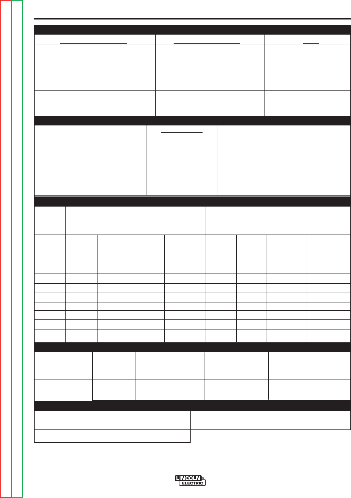
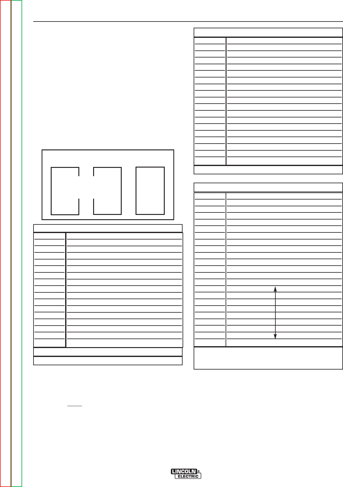
TECHNICAL SPECIFICATIONS-
PRECISION TIG 275 (Domestic, Canadian & Export
Voltage + 10%
208/230/460
460/575
220-230/
380-400/415
Max. Amps With Out
Power Factor Capacitor
104/94/47
124/112/56
86/78/39
95/86/43
77/70/35
73/66/33
6/5/3
47/38
56/45
39/31
43/35
35/28
33/26
3/2
300W
95/55/50
109/63/58
80/46/42
85/49/45
70/41/37
65/38/35
10/6/5
400W
Max. Amps With
Power Factor Capacitor
80/72/36
95/86/43
64/58/29
62/56/28
55/50/25
40/36/18
36/32/16
35/28
43/34
29/23
28/23
25/20
18/14
16/13
500W
80/46/43
86/50/46
64/37/34
67/39/36
52/30/28
46/27/25
23/13/12
500W
Duty Cycle-Applications
40%
AC/DC Stick / Balance TIG
Unbalance (70% Penetration#) AC TIG
60%
AC/DC Stick / Balance TIG
Unbalance (70% Penetration#) AC TIG
100%
AC/DC Stick / Balance TIG
Unbalance (70% Penetration#) AC TIG
Idle Amps
40%
AC/DC Stick / Balance TIG
Unbalance (70% Penetration#) AC TIG
60%
AC/DC Stick / Balance TIG
Unbalance (70% Penetration#) AC TIG
100%
AC/DC Stick / Balance TIG
Unbalance (70% Penetration#) AC TIG
Idle Amps
Idle Power
40%
AC/DC Stick / Balance TIG
Unbalance (70% Penetration#) AC TIG
60%
AC/DC Stick / Balance TIG
Unbalance (70% Penetration#) AC TIG
100%
AC/DC Stick / Balance TIG
Unbalance (70% Penetration#) AC TIG
Idle Amps
Idle Power
RATED INPUT - SINGLE PHASE ONLY
K
Number
K1825-1
K1826-1
K2619-1
K1826-2
K2619-2
K1827-1
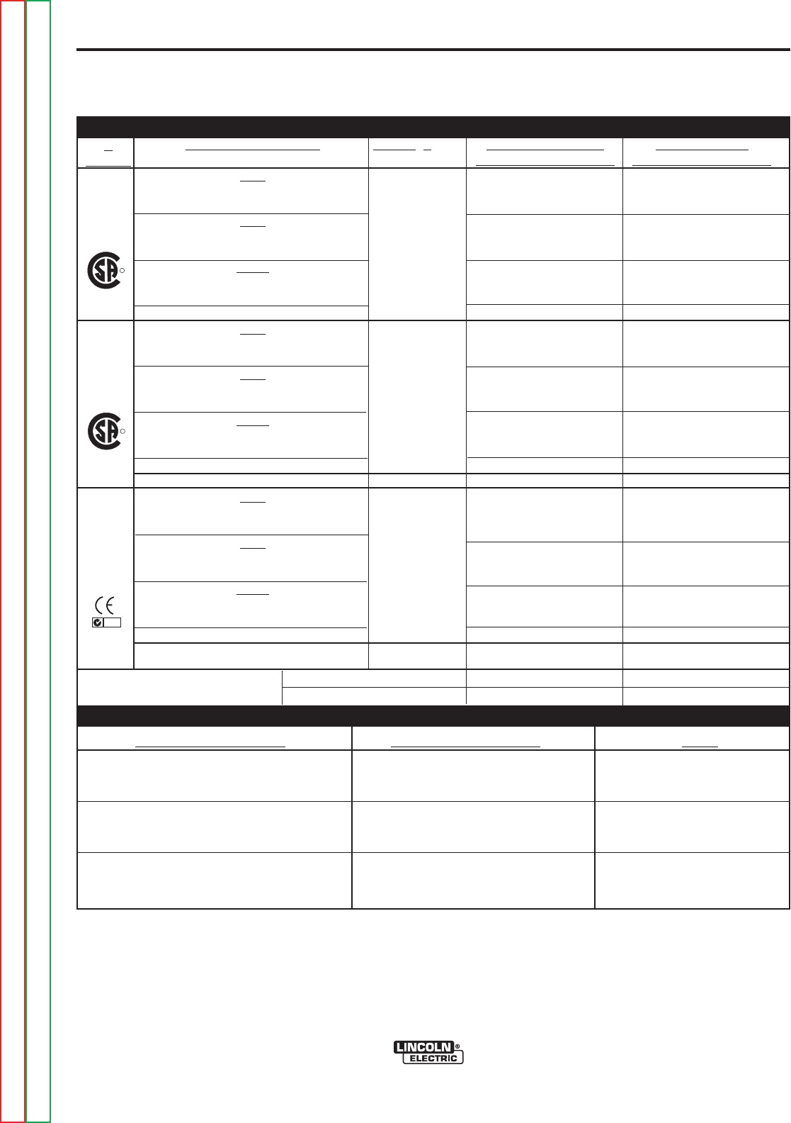
RATED OUTPUT - NEMA EW1 Class ll (40) K1825-1,K1826-1,-2, K2619-1.-2
Duty Cycle-Applications
40%
AC/DC Stick / Balance TIG
Unbalance (70% Penetration#) AC TIG
60%
AC/DC Stick / Balance TIG
Unbalance (70% Penetration#) AC TIG
100%
AC/DC Stick / Balance TIG
Unbalance (70% Penetration#) AC TIG
Volts at Rated Amperes
31.0
16.1
29.0
15.4
28.0
14.8
Amps
275
255
225
200
200
150
*Shown on Front of this IM manual with Under-Cooler Cart and Advanced Control Panel (Refer to Optional Equipment)
#Exceeds NEMA Unbalanced Load Specification comparable for Auto-Balance.
RATED POWER FACTOR (STICK) K1825-1,K1826-1 & K1826-2 .63 min. .85 min.
K1827-1 .65 min. .77 min.
R
R
NRTL/C
NRTL/C
IEC 60974-1
N80
Return to Section TOC Return to Section TOC Return to Section TOC Return to Section TOC
Return to Master TOC Return to Master TOC Return to Master TOC Return to Master TOC
K1826-1, -2
K1827-1
K2619-1,-2
K1825-1
A-3
INSTALLATION
PRECISION TIG 275
A-3
Return to Section TOC Return to Section TOC Return to Section TOC Return to Section TOC
Return to Master TOC Return to Master TOC Return to Master TOC Return to Master TOC
ADDITIONAL OUTPUT CAPACITY
Output Current
Range
2Amps DC
to
340Amps AC-DC*
Type of Output
CC (Constant Current)
AC/DC (GTAW)
Stick (SMAW)
Maximum Open
Circuit Voltage
(STICK AND TIG)
AC/DC OCV: 75/68
Auxiliary Power
K1825-1, K1826-1, K1826-2
15Amp Circuit Breaker and NEMA 5-15R Duplex
Receptacle for up to:
115VAC 8Amp Auxiliary Power Receptacle
115VAC weld Switched Cooler Receptacle load
K1834-1
5 Amp Circuit Breaker
and grounded 220VAC
Euro(Schuko) receptacle
Height Width Depth Weight
31.0 in. 22.0 in. 26.0 in. Approx. 397 lbs.
787 mm 559 mm 660 mm 180 kgs.
49.7 in. 28.0 in. 41.0 in. Approx.641 lbs.
1262 mm 711 mm 1041 mm 291 kgs.
PHYSICAL DIMENSIONS
1ALSO CALLED ʻINVERSE TIME" OR "THERMAL/MAGNETIC " CIRCUIT BREAKERS; CIRCUIT BREAKERS WHICH HAVE A DELAY IN TRIPPING ACTION THAT DECREASES AS
THE MAGNITUDE OF CURRENT INCREASES.
*50/60HZIEC Max. range exceeds 310A.
TEMPERATURE RANGES
OPERATING TEMPERATURE RANGE
-20°C to +40°C (-04° to +104°F)
TRANSFORMER INSULATION CLASS 180°C (H)
STORAGE TEMPERATURE RANGE
-40°C to +85°C (-40° to +185°F)
For all Stick, DC TIG, and Balanced AC TIG Welding
at 275A/40% Duty Cycle with out Standard Power
Factor Correction Capacitors
Based on the 1999 U.S. National Electrical Code
For Unbalanced AC TIG Welding Above 275 Amps:
255A/40% Duty Cycle, Auto-Balance Penetration with
out Standard Power Factor Correction Capacitors
Based on the 1999 U.S. National Electrical Code
RECOMMENDED INPUT WIRE AND FUSE SIZES
Input
Voltage /
phase/
Frequency
208/1/60
230/1/60
460/1/60
575/1/60
220-230/1/50/60
380-400/1/50/60
415/1/50/60
Input
Ampere
Rating
Rating on
Nameplate
104
94
47
38
95
55
50
Input
Ampere
Rating
124
112
56
45
109
63
58
Type 75°C
Copper
Ground Wire in
Conduit AWG
(IEC) Sizes
6 (13.3 mm2)
6 (13.3 mm2)
10 (5.3mm2)
10 (5.3mm2)
6 (13.3 mm2)
8 (8.4mm2)
8 (8.4mm2)
Type 75°C
Copper
Ground Wire in
Conduit AWG
(IEC) Sizes
6 (13.3 mm2)
6 (13.3 mm2)
8 (8.4 mm2)
10 (5.3mm2)
6 (13.3 mm2)
8 (8.4 mm2)
8 (8.4 mm2)
Fuse
(Super Lag)
or Breaker
Size1
125
125
60
50
125
80
80
Fuse
(Super Lag)
or Breaker
Size1
150
150
70
60
150
90
90
Type 75°C
Copper Wire in
Conduit AWG
(IEC) Sizes
40°C (104°F)
Ambient
4 (21.2 mm2)
4 (21.2 mm2)
8 (8.4mm2)
10 (5.3mm2)
4 (21.2 mm2)
8 (8.4mm2)
8 (8.4mm2)
Type 75°C
Copper Wire in
Conduit AWG
(IEC) Sizes
40°C (104°F)
Ambient
3 (26.7 mm2)
3 (26.7 mm2)
8 (8.4 mm2)
8 (8.4 mm2)
4 (21.2 mm2)
6 (13.3 mm2)
6 (13.3 mm2)
RATED OUTPUT - IEC 60974-1 (K1827-1)
Duty Cycle-Applications
40%
AC/DC Stick / Balance TIG
Unbalance (70% Penetration#) AC TIG
60%
AC/DC Stick / Balance TIG
Unbalance (70% Penetration#) AC TIG
100%
AC/DC Stick / Balance TIG
Unbalance (70% Penetration#) AC TIG
Volts at Rated Amperes
31.0
20.2
29.0
18.0
28.0
16.0
Amps
275
255
225
200
200
150

A-4
PRECISION TIG 275
A-4 INSTALLATION
SAFETY PRECAUTIONS
Read entire Installation Section before installing
the Precision Tig 275.
ELECTRIC SHOCK can kill.
• Only qualified personnel should per-
form this installation.
• Turn the input power OFF
at the disconnect switch or
fuse box and discharge input capacitors
before working inside the equipment.
• Do not touch electrically hot parts.
• Always connect the Precision Tig grounding screw (behind
the reconnect panel cover located near the back of the left
case side) to a good electrical earth ground.
• Always connect the Precision Tig to a power supply grounded
in accordance with the National Electrical Code and all local
codes.
SELECT SUITABLE LOCATION
Place the welder where clean cool air can freely circu-
late in through the rear louvers and out through the bot-
tom opening. Dirt, dust or any foreign material that can
be drawn into the machine should be kept at a mini-
mum. Failure to observe these precautions can result
in excessive operating temperatures and nuisance
trips.
GRINDING
Do not direct grinding particles towards the welder. An
abundance of conductive material can cause mainte-
nance problems.
STACKING
The Precision Tig 275 cannot be stacked.
UNDERCARRIAGE LIFTING AND MOVING
When the Precision TIG 275 is purchased as a welding
package, or used with any of the available
Undercarriage optional accessories, proper installation
makes the Precision TIG 275 lift bale nonfunctional.
Do not attempt to lift the power source with an under-
carriage attached. The undercarriage is designed for
hand moving only; mechanized movement can lead to
personal injury and/or damage to the Precision TIG
275.
TILTING
Each machine must be placed on a secure, level sur-
face, either directly or on a recommended undercar-
riage.
The machine may topple over if this precaution is not
followed.
ENVIRONMENTAL RATING
Precision TIG 275 power sources carry an IP21S
Environmental rating. They are rated for use in damp,
dirty rain-sheltered environments.
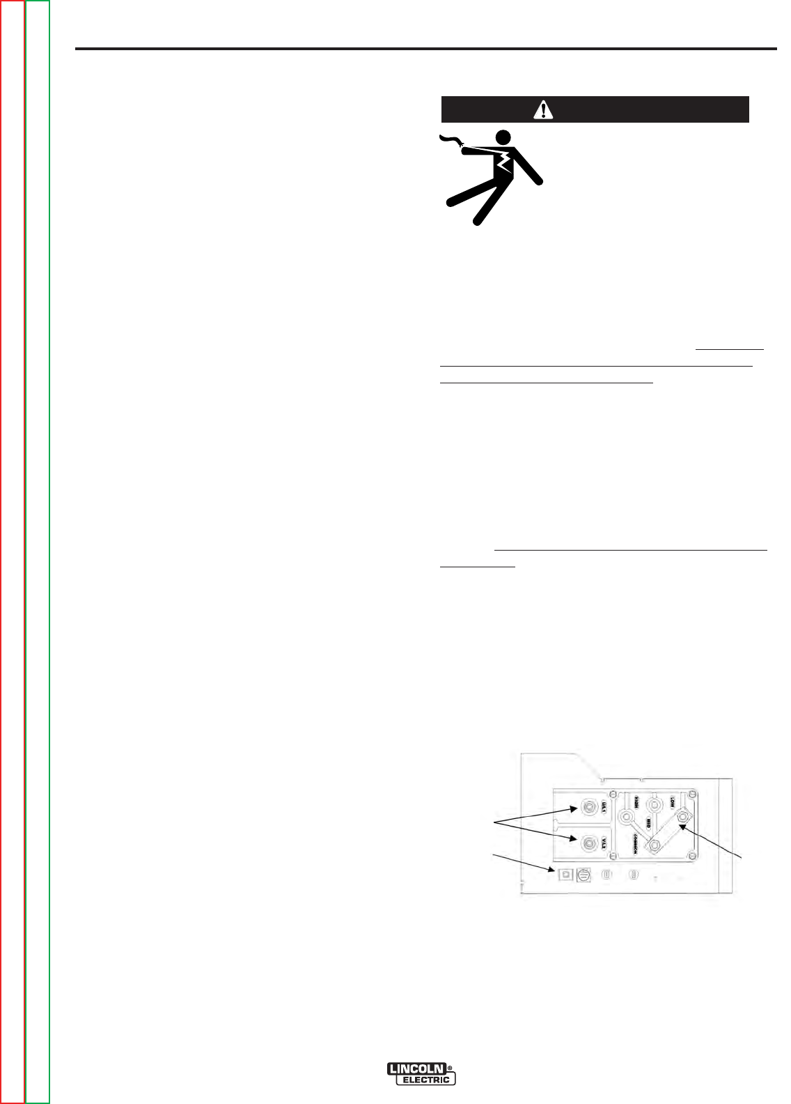
HIGH FREQUENCY INTERFERENCE
PROTECTION
The frame of the welder must be grounded. A ground
screw marked with the symbol is located on the
input connection panel (Figure A.1) for this purpose.
See your local and national electrical codes for proper
grounding methods.
The spark gap oscillator in the high frequency genera-
tor, being similar to a radio transmitter, can be blamed
for many radio, TV and electronic equipment interfer-
ence problems. These problems may be the result of
radiated interference. Proper grounding methods can
be reduced or eliminate re-radiated interference.
The Precision TIG 275 has been field tested under rec-
ommended installation conditions and has been found
to comply with F.C.C. allowable radiation limits. This
welder has also been found to comply with NEMA stan-
dards for high frequency stabilized power sources.
Radiated interference can develop in the following four
ways:
* Direct interference radiated from the welder.
* Direct interference radiated from the welding leads.
* Direct interference radiated from the feedback into
the power lines.
* Interference from re-radiation of “pickup” by
ungrounded metallic objects.
Keeping these contributing factors in mind, installing
the equipment per the following instructions should
minimize problems.
1. Keep the welder power supply lines as short as pos-
sible and completely enclose them in rigid metallic con-
duit or equivalent shielding for a minimum distance of
50 feet (15.2 m). There must be good electrical contact
between this conduit must be connected to a driven
ground and the entire length must be continuous.
2. Keep the work and electrode leads as short as pos-
sible and as close together as possible. Lengths
should not exceed 25 feet (7.6m). Tape the leads
together when practical.
WARNING
Return to Section TOC Return to Section TOC Return to Section TOC Return to Section TOC
Return to Master TOC Return to Master TOC Return to Master TOC Return to Master TOC
A-5
INSTALLATION
A-5
PRECISION TIG 275
Return to Section TOC Return to Section TOC Return to Section TOC Return to Section TOC
Return to Master TOC Return to Master TOC Return to Master TOC Return to Master TOC
3. Be sure the torch and work cable rubber coverings
are free of cuts and cracks that allow high frequen-
cy leakage. Cables with high natural rubber content,
such as Lincoln Stable-Arc Rbetter resist high fre-
quency leakage than neoprene and other synthetic
rubber insulated cables.
4. Keep the torch in good repair and all connections
tight to reduce high frequency leakage.
5. The work terminal must be connected to a ground*
within ten feet of the welder, using one of the follow-
ing methods.
* A metal underground water pipe in direct contact
with the earth for ten feet or more.
* A 3/4” (19mm) galvanized pipe or a 5/8” (16mm)
solid galvanized iron, steel or copper rod driven at
least eight feet into the ground.
The ground should be securely made and the ground-
ing cable should be as short as possible using cable of
the same size as the work cable, or larger. Grounding
to the building frame electrical conduit or a long pipe
system can result in re-radiation, effectively making
these members radiating antennas. (This is not recom-
mended.)
6. Keep all access panels and covers securely in
place.
7. All electrical conductors within 50 feet (15.2m) of the
welder should be enclosed in grounded rigid metal-
lic conduit or equivalent shielding. Flexible helically-
wrapped metallic conduit is generally not suitable.
8. When the welder is enclosed in a metal building,
several earth driven electrical grounds (as in 5
above) around the periphery of the building are rec-
ommended.
Failure to observe these recommended installation
procedures can cause radio or TV interference prob-
lems and result in unsatisfactory welding performance
resulting from lost high frequency power.
INPUT and GROUNDING CONNECTIONS
ELECTRIC SHOCK can kill.
* Turn the input power OFF at the
disconnect switch or fuse box
before working on this equip-
ment.
___________________________________________
Be sure the voltage, phase, and frequency of the
input power is as specified on the rating plate, located
on the rear of the machine.
Fuse the input circuit with the recommended super
lag fuses or delay type1 circuit breakers. Choose an
input and grounding wire size according to local or
national codes or use Section A-2. Using fuses or cir-
cuit breakers smaller than recommended may result
in “nuisance” tripping from welder inrush currents
even if not welding at high currents.
Unbalanced AC TIG welding draws higher input cur-
rents than those for Stick, DC TIG, or Balanced AC
TIG welding. The welder is designed for these higher
input currents. However, where unbalanced AC TIG
welding above 185 amps is planned, the higher input
currents require larger input wire sizes and fuses per
Section A-2:
Remove the reconnect panel cover located near the
back of the left case side to reveal the reconnected
panel. Welder supply line entry provision is in the
case rear panel. Entry is through a 1.75 inch (44mm)
diameter hole in the case back. Appropriate supply
line strain relief clamp is provided by installer. (See
Figure A.1)
All connections should be made in accordance
with all local codes and national electrical codes.
Installation by a qualified electrician is recom-
mended.
WARNING
FIGURE A.1
CONNECT INPUT
POWER LEADS
CONNECT INPUT
VOLTAGE LEVEL
CONNECT INPUT
GROUND LEAD
A-6
INSTALLATION
PRECISION TIG 275
A-6
Recommended Cable Sizes for Combined Lengths of
Copper Work and Electrode Cables using 75oC Wire:
Machine Rating 0 to 100 Ft. 101 to 200 Ft 201 to 250 Ft
275A/40% #1 (42.4 mm2) 1/0 (53.5 mm2) 2/0 (67.4 mm2)
WORK CABLE CONNECTION
A 15ʼ (2/0) weld cable with clamp is available (K2150-1), or
included with the Precision TIG Welding Package model.
Otherwise, it is user provided.
With power source off, connect a separate work cable
to the 1/2-13 threaded "WORK" stud of the welder, and
secure a tight connection with the flange nut provided.
The work cable should be routed through the cable
strain relief hole provided in the base directly below the
welding output terminal.
Note: If the Precision TIG is equipped with an Under-
Cooler or Under-Storage unit, the coiled work cable
and clamp, or excess work cable length, may be con-
veniently stored in the drawer while remaining con-
nected.
STICK ELECTRODE CABLE CONNECTION
If manual stick welding is desired, with power source
off, connect a stick electrode cable to the 1/2-13
threaded "STICK Electrode" stud of the welder, and
secure a tight connection with the flange nut provided.
The electrode cable should be routed through the
cable strain relief hole provided in the base directly
below the welding output terminal.
DISCONNECT STICK ELECTRODE WELDING
CABLE WHEN TIG WELDING.
EVEN THOUGH HI-FREQ IS NOT APPLIED TO THE
PRECISION TIG STICK TERMINAL, IT WILL BE
ELECTRICALLY "HOT" TO WORK WHEN TIG
WELDING.
------------------------------------------------------------------------
1. Connect the terminal marked (below the recon-
nect panel) to an earth ground.
2. Connect the input leads to terminals marked L1 (U)
and L2 (V) on the reconnect panel. Use a single
phase line or one phase of a two or three phase line.
3. On multiple input voltage welders, be sure the
reconnect panel is connected for the voltage being
supplied to the welder.
Failure to follow these instructions can cause
immediate failure of components within the welder.
------------------------------------------------------------------------
Welders are shipped connected for the highest input
voltage as listed on the rating plate. To change this
connection, designations on the reconnect panel LOW,
MID, and HIGH correspond to the name plated input
voltages of a triple voltage welder. Dual voltage
welders use only LOW and HIGH.
EXAMPLE: On a 208/230/460 volt welder, LOW is
208V, MID is 230V, and HIGH is 460V.
NOTE: Export model has a voltage range for LOW and
MID connections: LOW is 220-230V, MID is 280-
400V and high is 415V.
Reconnect the jumper strap to the terminal stud corre-
sponding to the input voltage level used. Make sure all
connections are tight.
OUTPUT CABLES, CONNECTIONS AND
LIMITATIONS
• To avoid being startled by a high frequency
shock, keep the TIG torch and cables in good
condition
• Turn the power switch of the power source OFF
before installing adapters on cable or when con-
necting or disconnecting adapter plugs to power
source.
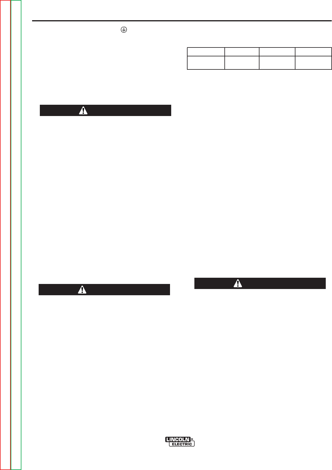
-----------------------------------------------------------------------
Refer to Figure A.2 for the location of the WORK and
STICK terminals, as well as the TIG Torch connection
panel.
WARNING WARNING
CAUTION
Return to Section TOC Return to Section TOC Return to Section TOC Return to Section TOC
Return to Master TOC Return to Master TOC Return to Master TOC Return to Master TOC
A-7
INSTALLATION
PRECISION TIG 275
A-7
Return to Section TOC Return to Section TOC Return to Section TOC Return to Section TOC
Return to Master TOC Return to Master TOC Return to Master TOC Return to Master TOC
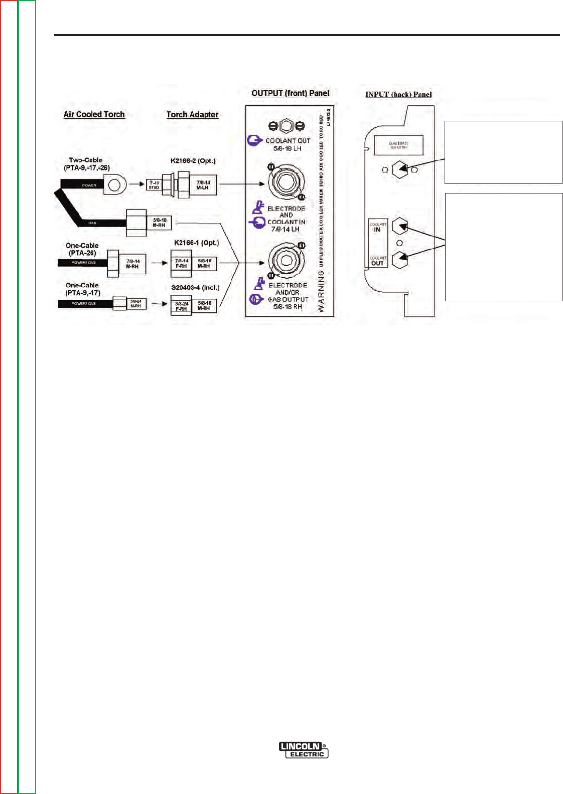
TIG TORCH CONNECTION
The Precision TIG torch connection box, located on the
right side of the machine, provides all the input and
output connections for the installation of both air-
cooled and water-cooled TIG torches with fittings con-
forming to Compressed Gas Association (CGA) stan-
dards:
Note: The Precision TIG provides an insulated Torch
Reel and Holster for handy and safe storage of con-
nected torch when not welding, and excess torch cable
length while welding.
Combination connectors (Power/Water and
Power/Gas) are electrically "hot" while welding in
STICK or TIG modes.
If using an Air-Cooled Torch be sure coolant is
shut off and/or Cooler is unplugged from the
Precision TIG Water Cooler Receptacle on the
torch side of the upper case back.
Observe the safety precautions necessary for han-
dling and using compressed gas containers.
Contact your supplier for specifics.
CYLINDER could explode
if damaged.
• Keep cylinder upright and
chained to a support.
• Keep cylinder away from areas
where it could be damaged.
• Never allow the torch to touch the cylinder.
• Keep cylinder away from live electrical cir-
cuits.
• Maximum inlet pressure 150 psi.
-----------------------------------------------------------------
The Precision TIG machines do not have Hi-Freq.
available at the Stick electrode stud, therefore stud
connection adapters (such as LECO. S19257-series)
cannot be used for torch connection.
Single-piece cable air-cooled torches with a 3/8-24 RH
connector fitting (such as the Magnum PTA-9/-17, or LA-
9/-17) require the provided S20403-4 Torch Connector,
while those with a 7/8-14 RH connector fitting (such as
the Magnum PTA-26, or LA-26) require the available
K2166-1 Torch Connector. (See Figure A.3)
Two-piece cable air-cooled torches (such as PTA-, or LA-
torches) can be used with the available 1/2” Stud
Connector (S20403-3) with with a 7/8-14 LH male fitting.
Magnum PTW-18/-20 (or LW-) water-cooled Torches
require no adapter for Precision TIG connection.
WARNING
WORK
STICK
WORK
STICK
STICK
ELECTRODE
STUD
WORK
STUD
TIG TORCH
CONNECTION
PANEL
FIGURE A
(Shown without hinged stud cover)
REMOTE
CONTROL
RECEPTACLE
CABLE
STRAIN
RELIEF HOLES
FIGURE A.2
A-8
INSTALLATION
PRECISION TIG 275
A-8
AUXILIARY POWER CONNECTIONS
The Precision TIG machines provide a standard NEMA
5-15R duplex receptacle, located on the upper case
back on the torch side of the machine:
• The bottom outlet of this duplex receptacle provides
switched 115VAC power for the Under-Cooler, or
Water Solenoid accessory. This Cooler receptacle
turns on when the arc starts and remains on for about
8 minutes after the arc goes out (with the Fan-As-
Needed machine cooling fan, see Maintenance
Section), so the Coolerʼs fan and water pump will not
run continuously in idle, but will run while welding.
• The top outlet of this duplex receptacle provides at
least 8 amps at 115VAC, whenever the Precision TIG
Power switch is ON. This auxiliary circuit is intended
for running 115VAC accessories or small power tools.
Note: Some types of equipment, especially pumps
and large motors, have starting currents which are
significantly higher than their running current. These
higher starting currents may cause the circuit breaker
to open. (See next paragraph)
• Both the receptacle circuits are protected from shorts
and overloads by a 15 amp circuit breaker, located
above the receptacle. if the breaker trips its button
pops out exposing a red ring. When the circuit break-
er cools the button can be reset by pressing it back
in.
Note: When the breaker trips not only will the auxil-
iary and cooler power be interrupted, but so will the
power to the shielding gas solenoid and machine
cooling fan.
The Precision TIG Export models also provide a
grounded 220 VAC Euro type Schuko receptacle and a
5 amp circuit breaker, located on the upper case back
on the reconnect side of the machine, intended for use
with a 220 VAC water cooler.
REMOTE CONTROL (If Used)
The Foot Amptrol (included with the Precision TIG
Welding Package), or other Remote accessory, is
installed by routing the plug of its control cable up
through the left cable strain relief hole provided in the
base (see Figure A.2), then connecting the 6-pin plug
to the mating Remote receptacle behind the stud panel
cover. (See Operation Section B-2 for mating plug
wiring.)
Note: If the Precision TIG is equipped with an Under-
Cooler or Under-Storage unit, the Foot Pedal (or other
remote control accessory) and coiled control cable, or
excess cable length, may be conveniently stored in the
drawer while remaining connected.
FIGURE A.3
For Gas Supply hose
with 5/8-18RH male
(Provided with Weld
Package model)
For Coolant Supply
Hoses
with 5/8-18LH male
(Provided with Weld
Package model
or
Under-Cooler Cart)
Return to Section TOC Return to Section TOC Return to Section TOC Return to Section TOC
Return to Master TOC Return to Master TOC Return to Master TOC Return to Master TOC
A-9
INSTALLATION
PRECISION TIG 275
A-9
ROBOTIC INTERFACE CONNECTION
Robotic interface can be made at the Remote
Receptacle (See Operation Section). The machine is
shipped with the remote receptacle circuit internally
connected to receptacle J5 of the Control board for
standard Amptrol operation. In order to enable the
remote receptacle for robotic interface its connection
plug must be moved from J5 to J5A on the Control
board. (Refer to the machine Wiring Diagram.)
The robotic interface functions with the Precision TIG
set to either TIG or STICK mode, but must be in
REMOTE switch position for the Preset Control inter-
face to function. When in the REMOTE position with
robotic interface neither the MAXIMUM OUTPUT nor
the MINIMUM OUTPUT panel controls limit the inter-
face control setting over the rated output range of the
machine.
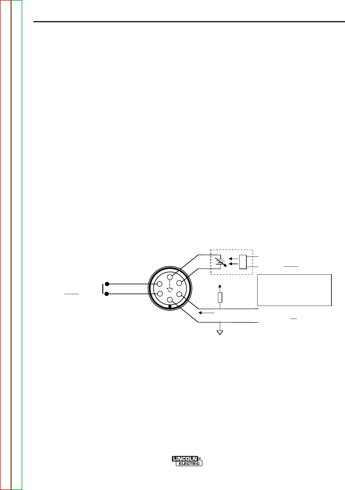
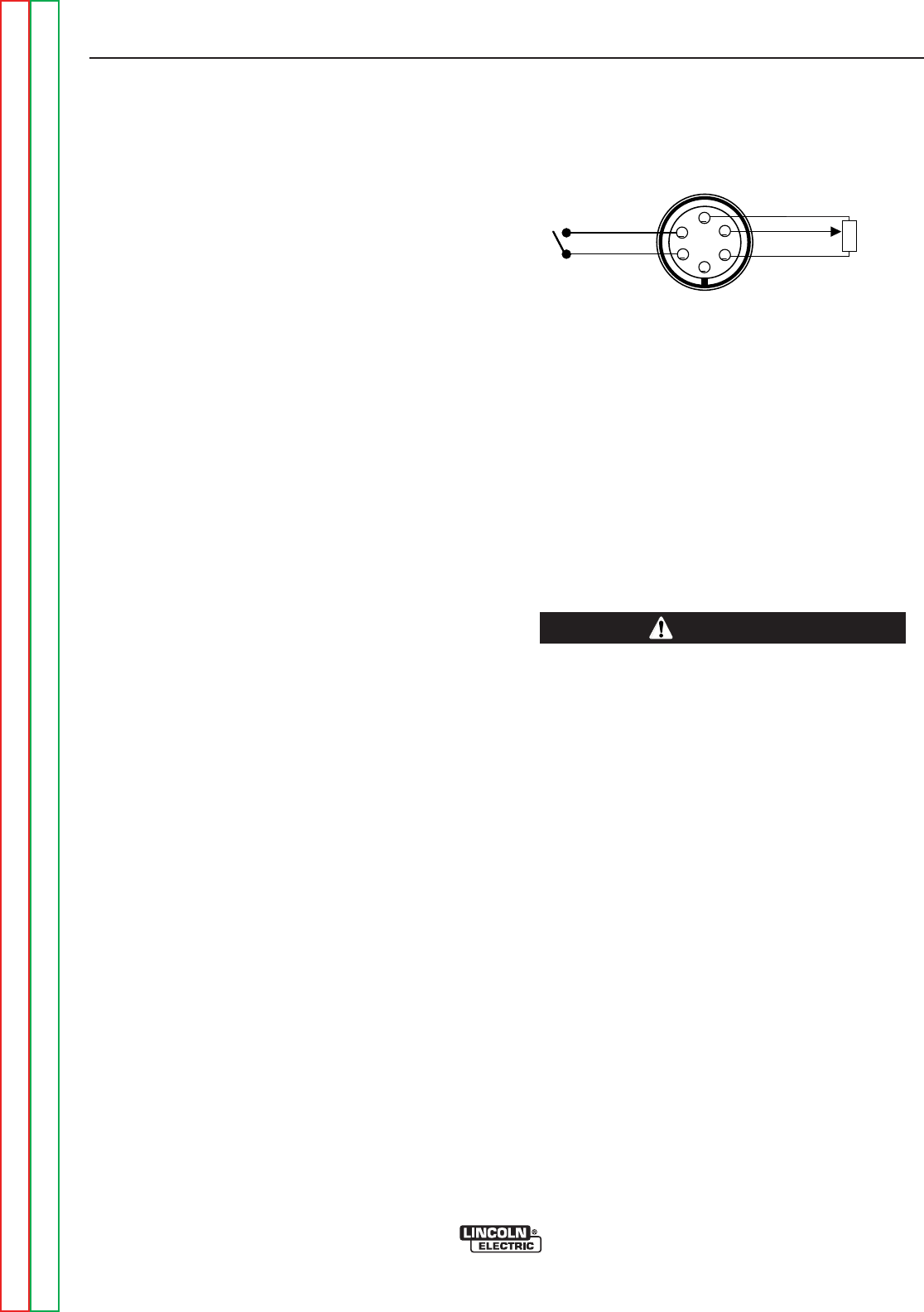
The diagram in Figure A.4 below shows the remote
receptacle plug connections and signals for robotic
interface:
Return to Section TOC Return to Section TOC Return to Section TOC Return to Section TOC
Return to Master TOC Return to Master TOC Return to Master TOC Return to Master TOC
+VCC = 70Vdc max.
R = VCC / 5ma
5ma
Robotic
Common
A
B
C
D
E
F
REMOTE RECEPTACLE
(Front View)
For 18-12P Plug
(LECO S12020-27)
ARC START
INPUT FROM ROBOT
(18Vac,10ma switch)
*
+
PRESET CONTROL
INPUT FROM ROBOT
(0 -10Vdc = Rated Output Range)
ARC ESTABLISHED
OUTPUT TO ROBOT
(High = Not Welding)
(Low = Welding)
* Precision TIG Control Common.
Note: The Interface connection
cable may pick up noise
interference. Additional
bypass/filtering circuits may be
needed for the external circuits.
FIGURE A.4


B-1
B-1
PRECISION TIG 275
Return to Master TOC Return to Master TOC Return to Master TOC Return to Master TOC
TABLE OF CONTENTS
- OPERATION SECTION -
Operation ...............................................................................................................................Section B
Safety Precautions ......................................................................................................................B-2
Product Description.....................................................................................................................B-2
Recommended Process and Equipment ....................................................................................B-3
Controls and Settings..................................................................................................................B-4
Welding Operation................................................................................................................B-5/B-8
Internal Set Up Controls..............................................................................................................B-9
2 Step Trigger Modes................................................................................................................B-10
4 Step Trigger Modes................................................................................................................B-11
TIG Weld Cycle Chart ...............................................................................................................B-12
Set Up for TIG Amptrol Welding................................................................................................B-13
Making a TIG Weld with an Amptrol .........................................................................................B-14
Recommended Electrode Amperage Ranges...........................................................................B-14
SAFETY PRECAUTIONS
Read and understand this entire section before operat-
ing the machine.
ELECTRIC SHOCK CAN KILL.
*Only qualified personnel should per-
form the installation.
* Turn the input power OFF at the dis-
connect switch or fuse box.
* Do not touch electrically live parts or
electrode with skin or wet clothing.
* Insulate yourself from work and
ground.
* Always dry insulating gloves.
* Read and follow “Electric Shock
Warnings” in the Safety section if
welding must be performed under
electrically hazardous conditions
such as welding in wet areas or on
or in the workpiece.
......................................................................................
FUMES AND GASES
can be dangerous.
* Keep your head out of fumes.
*Use ventilation or exhaust to
remove fumes from breathing
zone.
......................................................................................
WELDING SPARKS
can cause fire and explosion
* Keep flammable material away.
* Do not weld on containers that
have held combustibles.
......................................................................................
ARC RAYS
can burn.
* Wear eye, ear and body protec-
tion.
......................................................................................
Observe additional Safety Guidelines detailed in
the beginning of this manual.
PRODUCT DESCRIPTION
The Precision TIG 275 is part of a new family of indus-
trial arc welding power sources providing constant cur-
rent, single range square wave AC/DC TIG (GTAW)
with new patented (pending) Micro-StartTM Technology,
Presettable Min. and Max. Output controls, and built-in
high frequency stabilization for continuous AC TIG and
DC TIG starting. It also has AC/DC Stick (SMAW)
capability, with adjustable Arc Force availability. A TIG
Pulse Panel. Power Factor Capacitors and a Water
Solenoid are available as field installed optional kits.
Also, a new Undercarriage (with double gas bottle
rack) is available for field installation, as well as a new
Under-Cooler Cart, which is also included in an avail-
able efficiently integrated entire TIG Welding Package
with convenient built-in storage provisions for welding
equipment and components.
The Precision TIG 275 includes advanced features
such as a Digital Meter, Presettable control, Auto
BalanceTM, Fan As Needed (F.A.N.) fixed Preflow, vari-
able Postflow shielding gas and Timers. In addition, 2-
Step/4-Step and Pulse TIG operation with adjustable
Downslope Time control are included with an available
field installed kit. It also features a Stick stud panel and
a universal TIG torch connection box for simultaneous,
but separated, electrode outputs.
The Precision TIG 275 has enhanced Features which
includes the following:
• MicroStart™ Codes Below 11000
• MicroStart™ II Codes Above 11000
• Auto-Balance optimized
• Menu button added
• Spot On selection added
PIPE THAWING
The Precision TIG 275 is not recommended for pipe
thawing.
Duty Cycle
The duty cycle is based upon a 10-minute time period;
i.e., for 40% duty cycle, it is 4 minutes welding and 6
minutes idling. If the rated duty cycle is significantly
exceeded, the thermostatic protection will shut off the
output until the machine cools to a normal operating
temperature. (Refer to Specification Section A-1)
B-2
OPERATION
B-2
PRECISION TIG 275
WARNING
Return to Section TOC Return to Section TOC Return to Section TOC Return to Section TOC
Return to Master TOC Return to Master TOC Return to Master TOC Return to Master TOC

B-3
OPERATION
B-3
RECOMMENDED PROCESSES
The Precision TIG 275 is recommended for the TIG
(GTAW) and Stick (SMAW) welding processes within
its output capacity range of 2 amps DC, or 5 amps AC,
to 340 amps AC/DC. It is compatible with most
Magnum TIG accessories (refer to Equipment
Limitations), as well as many industry standard items,
such as TIG torches, hoses, and water coolers.
PROCESS LIMITATIONS
Precision TIG machines are not recommended for arc
gouging due to it's limited output capacity, and are also
not recommended for pipe thawing.
EQUIPMENT LIMITATIONS
The Precision TIG machines are protected from over-
loads beyond the electrical ratings and duty cycles, per
the Specifications Section A-2, A-3, with Thermostat
protection of the primary and secondary transformer
coils.
The Precision TIG machines do not have Hi-Freq.
available at the Stick electrode stud, therefore stud
connection adapters (such as LECO. S19257-series)
cannot be used for torch connection.
PRECISION TIG 275
Return to Section TOC Return to Section TOC Return to Section TOC Return to Section TOC
Return to Master TOC Return to Master TOC Return to Master TOC Return to Master TOC
RECOMMENDED EQUIPMENT/INTERFACE FOR CODES ABOVE 11000
TIG (water cooled) TIG (air cooled)
Machine: PT275 Welding Package (K2618-1) PT275(K2619-1,-2)
Input Cable/Clamp: User provided User provided
Gas Reg./Hose: (included) LE/Harris 3100211
Magnum Torch: (PTW20 included) PTA9 or PTA17
Magnum Parts: (KP510 and K918-2 included) KP507 or KP508
Work Clamp/Lead: (15 ft. included) K2150-1 Work Lead Assembly
Foot Amptrol: (K870 included) K870
RECOMMENDED PROCESSES AND
EQUIPMENT
RECOMMENDED EQUIPMENT/INTERFACE FOR CODES BELOW 11000
TIG (water cooled) TIG (air cooled)
Machine: PT275 Welding Package (K1825-1) PT275(K1826-1, -2, K1827-1)
Input Cable/Clamp: User provided User provided
Gas Reg./Hose: (included) LE/Harris 3100211
Magnum Torch: (PTW20 included) PTA9 or PTA17
Magnum Parts: (KP510 and K918-2 included) KP507 or KP508
Work Clamp/Lead: (15 ft. included) K2150-1 Work Lead Assembly
Foot Amptrol: (K870 included) K870 or K870-1
B-4
OPERATION
B-4
1. POWER SWITCH - Input line switch turns input
power ON or OFF, as indicated by the on or off sta-
tus of the front panel displays.
2. POLARITY SWITCH – The 3-position rotary power
switch has detente positions for DC-, AC and DC+
selections for the Electrode output welding polarity.
3. MODE SWITCH – The mode switch allows vertical-
ly positioned selection of the two machine welding
modes. The selected mode is indicated by a lit col-
ored panel light which permits viewing the machine
setting from a distance:
3.a STICK mode (Top position) –Red panel light
ELECTRIC SHOCK can kill.
• When the Power Source is ON in
STICK mode the Electrode circuits of
both the Stick and TIG torch cables
are electrically HOT to Work.
------------------------------------------------------------------------
• The CC Stick mode may be used for general pur-
pose stick welding (SMAW ) within the capacity of
the machine. The capacity is too limited for air car-
bon arc gouging (CAC-A).
• In this mode; the output terminals are activated
electrically HOT, gas flow is not activated and HOT
START and ARC FORCE levels are fixed, or
Advanced Panel selectable (See Section B-7 ), with
no front panel adjustment.
3.b TIG mode (Bottom position) – No panel light.
• When the Polarity Switch is set to AC, the TIG
mode provides continuous high frequency to stabi-
lize the arc for AC TIG welding.
• Hi-Freq. turns on after preflow time with the arc
start switch closure, and turns off when the arc
goes out* after the arc start switch opens.
* Arc voltage and current are sensed to determine if
the arc is established or out.
PRECISION TIG 275
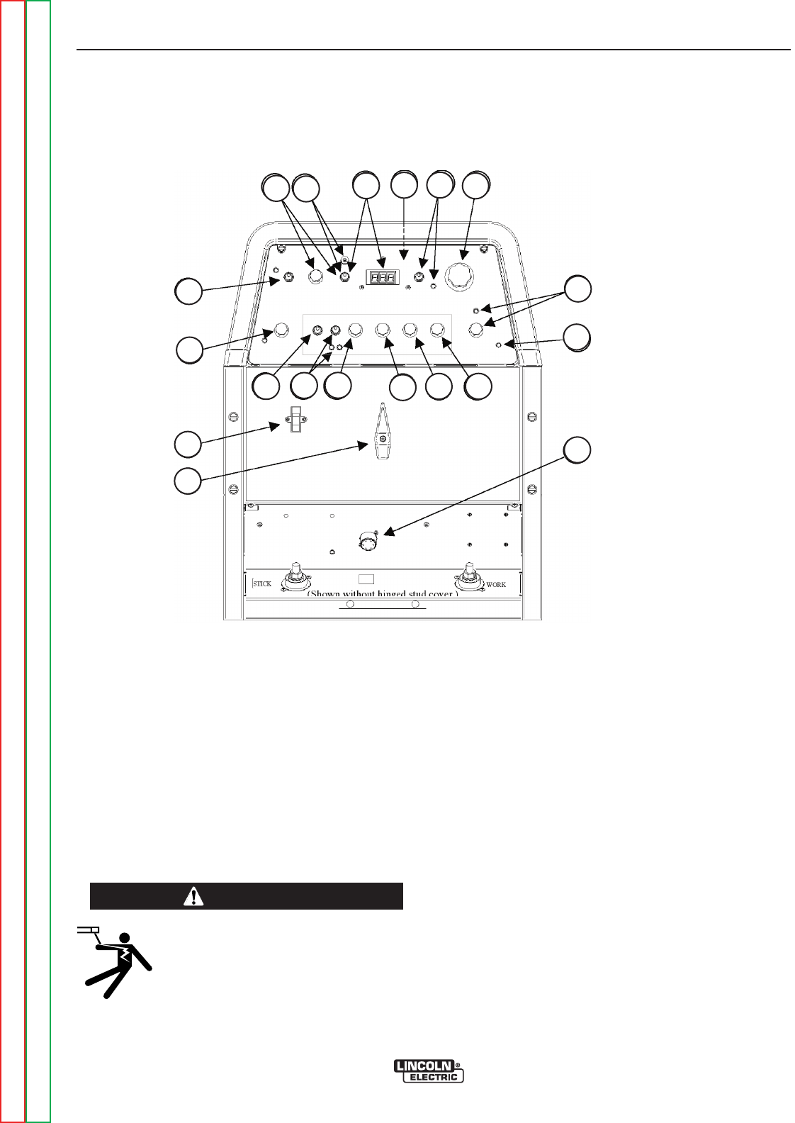
CONTROLS AND SETTINGS
The Front Control Panel contains the knobs and switches necessary for adjusting the operation of the Precision
TIG 275, with function indicator lights and an electronic display for volts and amps. The components are
described below:
FIGURE B.1 - CONTROL PANEL
WARNING
Return to Section TOC Return to Section TOC Return to Section TOC Return to Section TOC
Return to Master TOC Return to Master TOC Return to Master TOC Return to Master TOC
11
10
9
17
16
15
14
13
12
1
2
3
77a 8956
4
1. POWER SWITCH
2. POLARITY SWITCH
3. MODE SWITCH
4. AC BALANCE CONTROL
5. LOCAL/REMOTE
CURRENT CONTROL
SWITCH
6. MAXIMUM OUTPUT CONTROL
7. MINIMUM OUTPUT CONTROL AND
DISPLAY SWITCH
7.a MENU BUTTON AND DISPLAY
SWITCH FOR CODES ABOVE 11000
8.
DIGITAL METER AND DISPLAY
SWITCH
9. POSTFLOW TIME
10. THERMAL SHUTDOWN LIGHT
11. REMOTE RECEPTACLE
12. TRIGGER SWITCH
13. PULSE MODE SWITCH
14. PULSE FREQUENCY CONTROL
15. PULSE % ON TIME CONTROL
16. PULSE BACKGROUND CURRENT
CONTROL
17. DOWNSLOPE TIME

B-5
OPERATION
B-5
• When the Polarity Switch is set to DC (- or +), the
TIG mode provides high frequency only for starting.
• Hi-Freq. turns on after pre-flow time with the arc
start switch closure, and turns off when the arc is
established*
• DC+ polarity can also be used for ”balling” of the
tungsten for AC TIG welding.
4. AC BALANCE CONTROL – The potentiometer
control permits AC wave balance adjustment from
Max. Penetration (~85% negative wave) with the
control at Max. full CW position, to Max. Cleaning
(~65% positive wave) with the control set near min-
imum CCW position.
• Full minimum CCW position is the Auto Balance
position which is indicated by the Green panel light
turning on. This feature automatically provides the
proper amount of cleaning and penetration for nor-
mal AC TIG welding
• The mid position is the Balanced position (~50%
positive and negative waves).
• The Balance control is only functional if the machine
is set to AC polarity and TIG mode.
5. LOCAL/REMOTE
CURRENT CONTROL SWITCH
– A
2-position switch selects how the welding output is
controlled for both Stick and TIG Modes:
• LOCAL (Top position) selects output control only by
the machine panel Output Control. (See Item 6)
• REMOTE (Bottom position) selects output control to
also be by an Amptrol (See Item 6), or other remote
(10K pot) control connected to the Remote recepta-
cle (See Item 11) This switch selection is indicated
by the Green panel light turning on.
In either position the arc start switch functions when
connected to the Remote receptacle (See Item 11).
6. MAXIMUM OUTPUT CONTROL – The large knob
is used to set the output welding current over the
rated output range of the machine.
• With the Current Control switch to LOCAL position,
this knob sets the welding output level.
• With the Current Control switch to REMOTE posi-
tion, this knob sets the maximum welding level that
the Peak output can be set with the remote Amptrol.
• The new MicroStartTM Technology minimum current
circuit provides for low end welding (down to 2
amps) previously unobtainable on an SCR platform
TIG machine.
7. MINIMUM OUTPUT CONTROL AND DISPLAY SWITCH
–
A smaller knob is used to preset the minimum cur-
rent level only for TIG mode. Pressing the Display
(momentary) switch toggle left to Minimum Set posi-
tion displays the Minimum control level setting on the
Digital meter. (See Item 8)
• This knob sets the Start output level. When the arc
lights (using a new built-in TIG start pulse) this level
upslopes quickly (0.5 sec.w/ Advanced Panel, zero
w/o) and smoothly to the weld output level. The set-
ting range for this Start control is the 2 amp mini-
mum range of the machine up to about 50 amps, but
no more than the level set by the Maximum Output
control knob (See Item 6), but otherwise is indepen-
dent of the Maximum setting.
• This setting also serves as the Crater-fill level, but
with a Precision TIG Advanced Panel it can be
selected (see Section B-7) to be either the Minimum
Output control setting (same as Start setting) as
shipped, or the minimum rating of the machine (2
amps).
• The Remote Amptrol range of control is between
this Minimum setting and the Maximum Output con-
trol knob setting, so these knobs can set the resolu-
tion of the Amptrol. Also, the Minimum setting
serves as both the minimum Amptrol start level
when the arc start switch is closed, as well as the
minimum Amptrol crater-fill level before the arc start
switch is opened to help prevent premature arc out
and Hi-Freq re-initiation.
.
• In STICK mode the Start control is not functional
since Hot Start level is fixed, or internal Advanced
Panel adjustable (see Section B-7). Pressing the
Display (momentary) switch toggle left to Minimum
Output position displays minimum amps rating of
the machine.
PRECISION TIG 275
Return to Section TOC Return to Section TOC Return to Section TOC Return to Section TOC
Return to Master TOC Return to Master TOC Return to Master TOC Return to Master TOC
B-6
OPERATION FOR CODES ABOVE 11000 ONLY
B-6
PRECISION TIG 275
Return to Section TOC Return to Section TOC Return to Section TOC Return to Section TOC
Return to Master TOC Return to Master TOC Return to Master TOC Return to Master TOC
DIGITAL DISPLAYDIGITAL DISPLAY
(SET)
DISPLAY
(SELECT)
DISPLAY
7aaMENU BUTTON AND DISPLAY SWITCH (Codes
above 11000) – Pressing and holding the (Menu)
Button for about 5 seconds
enters
the menu display
which allows:
•
Selection
of up to seven programmable parameters
(Preflow, Upslope, Hot Start, Arc Force, etc.) on the
digital meter is achieved by momentarily pressing
and releasing the MENU button to step through the
parameters.
•
Setting
of the desired level, displayed on the digital
meter for the selected parameter, is done by press-
ing the DISPLAY (momentary) switch toggle to the
right to increase the level setting, or to the left to
decrease it.
Setting:
Selection 1:
0
1 *
2
Selection 2:
0
1
2 *
3
4
5
Selection 3:
0 *
1
2
∆
Description:
HF (High Freq.)
Scratch start TIG (No Hi-Freq.)
Normal Hi-Freq. start and weld
Lift TIG (Touch start w/o Hi-Freq.)
PF (Preflow time)
No Preflow
0.1 sec.
0.5 sec.
1.0 sec.
1.5 sec.
2.0 sec.
SS (MicroStart™ Start Pulse)
No AC pulse/Low DC pulse (soft start)
High AC/DC pulse (forceful start)
HS setting (see below) for each pulse when Pulse
mode welding anodized aluminum.
TIG Mode Menu
Setting:
Selection 4:
0 *
1
2
3
4
5
6
7
8
9
Selection 5:
0
1*
2
3
4
5
Description:
HS (TIG Hot Start % of output setting)
+0% (Only setting for SS0, above.)
+10%
+20%
+30%
+40%
+50%
+60%
+70%
+80%
+90%
UP (Upslope Time)
None (Only setting for SS1 & SS2, above.)
0.5 sec.
1.0 sec.
1.5 sec.
2.0 sec.
2.5 sec.
TIG Mode Menu (with Advanced Control Panel installed):
*Default Factory Setting. (Indicated by "blinking" decimal point.)
*Default Factory Setting. (Indicated by "blinking" decimal point.)
∆Only selectable with Advanced Control Panel installed.
Setting:
Selection 6:
0
1
2
3
4
5 *
6
7
8
9
Selection 7:
0
1 *
2
3
4
5
6
7
8
9
Description:
HS (Stick Hot Start % added to output setting)
+0%
+10%
+20%
+30%
+40%
+50%
+60%
+70%
+80%
+90%
AF (Stick Arc Force % added to output setting)
+0% ("Softer" arc)
+10%
+20%
+30%
+40%
+50%
+60%
+70%
+80%
+90% ("Crisper" arc)
STICK Mode Menu (with Advanced Control Panel installed
◊
):
*Default Factory Setting. (Indicated by "blinking" decimal point.)
◊If no Advanced Control Panel the Stick menu
displays “- - -“.
• Any of the following actions will exit the menu display:
1. Pressing and holding the (Menu) Button again for about 5 seconds.
2. Allowing the menu display to be unchanged for about 15 seconds.
3. Closing the arc start switch (TIG Mode) or starting the arc (Stick Mode).
Note: In Stick Mode the machine output will remain on while in menu display.
• Re-entering the menu displays the last parameter and setting that was displayed when the menu was
exited.
• All settings may be reset to the Factory Default Settings (above) by holding the (Menu) button pressed while
turning on the machineʼs Power switch. The display will show “rES” to indicate the defaults are reset.
B-7
OPERATION
B-7
8. DIGITAL METER AND DISPLAY SWITCH– A 3-
digit LED meter is used to monitor the preset and
actual welding procedure based on the Display
(momentary) switch position:
• Before welding with Display switch in center (nor-
mal) position, the digital meter displays the preset
welding amps set by Maximum Output control knob
(See Item 6). If in Stick mode using REMOTE (See
Item 5.), the digital meter displays the preset weld-
ing amps set by the Remote control. (See Item 11)
• While welding with Display switch in center (normal)
position, the digital meter displays the actual weld-
ing amps with one amp resolution (XXX) and accu-
racy within 4%+/-2A of reading.
• At any time in TIG mode, pressing the Display
switch to left causes the digital meter displays the
amps preset by the Minimum Output control knob
(See Item 7).
• At any time in Stick mode, pressing the Display
switch to left causes the digital meter to display the
minimum amps rating of the machine (See Item 7).
• In either mode, while pressing the Display switch
right to Volts position, the digital meter displays
actual output volts. Volts is displayed with 0.1 volt
resolution (XX.X) and accuracy within 3%+/-1V of
reading.
9. POSTFLOW TIME – This knob is used to set the
TIG mode shielding gas postflow time over the
range of about 2 to 60 seconds after the arc is shut
off. The postflow on time status is indicated by the
Green panel light.
• Gas preflow time for TIG mode is fixed at 0.5 sec-
onds, with no panel control.
• Both time ranges are x2 extendable, if needed, by
internal control box selection. (See Section B-7)
10. THERMAL SHUTDOWN LIGHT – This yellow LED
panel light turns on if the machine output is shut-
down because internal overheating has occurred,
and turns off when the thermostat resets.
11. REMOTE RECEPTACLE – A 6-socket receptacle
is provided for the connection of an Amptrol, or
other remote control: (See Figure B.2)
• When the Current Control Switch (See Item 5) is in
the REMOTE position, the Amptrol or other remote
(10K pot) connected to the Remote receptacle con-
trols the TIG or Stick mode output within the range
preset by the Maximum and Minimum Output con-
trols. (See Item 6, 7, and 8 for meter display.)
• When the Current Control Switch is in either
LOCAL
or REMOTE
positions the arc start switch functions
when connected to the Remote receptacle.
ADVANCED PANEL CONTROLS
The following controls are included only if the Precision
TIG 275 has the Advanced Control Panel (K1829-1)
option installed: (Refer to Figure B.3 Tig Weld Cycle
Chart for graphic illustration of these TIG welding func-
tions.)
12. TRIGGER SWITCH – This 2-position switch
selects how the arc start switch ( connected to the
above Remote receptacle) functions; in 2-Step or
4-Step mode:
• DO NOT USE 4-STEP IF USING AN AMPTROL
REMOTE.
• Neither the arc start switch nor the output con-
trol in the amptrol will function normally to shut
off or control the output. ONLY USE 2-STEP.
------------------------------------------------------------------------
• In 2-Step position the arc start switch functions the
same as without the Advanced Panel:
1. Closing switch starts preflow, then a fixed
(0.5 sec.) ramp time from Minimum (Start)
setting level (See Item 7) to Weld setting.
2. Opening switch initiates Downslope ramp
time setting (See Item 17), from Weld set-
ting to Crater-fill level (See Item 7), which
then stops the arc and initiates Postflow
time (See Item 9).
Note: See Figure B.3 for 2-Step operation during
Downslope with Restart feature selected to be dis-
abled, instead of enabled (as shipped).
PRECISION TIG 275
A
B
C
D
E
F
Max
10K ohm
Min
REMOTE RECEPTACLE*
(Front View)
REMOTE OUTPUT
CONTROL
ARC START
SWITCH
*For 18-12P Plug
(LECO S12020-27)
CAUTION
FIGURE B.2
Return to Section TOC Return to Section TOC Return to Section TOC Return to Section TOC
Return to Master TOC Return to Master TOC Return to Master TOC Return to Master TOC

B-8
OPERATION
B-8
• The 4-Step position allows welding without contin-
uously holding the start switch trigger. The arc start
switch functions in the following manner:
1. Closing the switch starts preflow, then arc
starts at Minimum (Start) setting level (See
Item 7). If the trigger is maintained closed
after preflow time the output remains at the
Start level until it is released.
2. Opening the switch initiates fixed (0.5 sec.)
ramp time from Start setting level to Weld
setting.
3. Reclosing the switch initiates Downslope
ramp time setting (See item 17) from Weld
setting down to the Crater-fill level (See
Item 7) of the machine.
4. Reopening the switch after Downslope time
holds Crater-fill level until it times out, then
stops the arc and initiates the Postflow Time
(See Item 9). Reopening switch during
Downslope time immediately stops the arc
and initiates the Postflow.
Note: See Figure B.4 for 4-Step operation during
Downslope with Restart feature selected to be
enabled, instead of disabled (as shipped).
13.PULSE MODE SWITCH (PULSE / SPOT MODE
SWITCH for codes above 11000) – Turns on the
Pulse Mode as indicated by the Green panel light
turning on.
• PULSE ON position provides a Peak current level
set by REMOTE and/or LOCAL control of the output
current (See Item5), for a time determined by the
Pulse Frequency Control setting (See Item 14) and
the % ON Time (See Item 15). The balance of the
cycle time is at the Background Current level (See
Item 16).
• Pulsing begins after upslope when the output cur-
rent rises above the Background Current level and
ends when the output current drops below this level
.
• SPOT ON position provides the peak current level
set by the Maximum Output Control for a time deter-
mined by the SPOT TIME control. A red panel light
is ON to indicate SPOT mode.
14. PULSE FREQUENCY CONTROL – This knob is
used to set the Pulse Frequency over the peak
pulse range of about 0.1 pps to 20 pps. (One pulse
cycle time = 1/pps = 10 to .05 sec. range.)
15. PULSE % ON TIME CONTROL (PULSE% ON /
SPOT TIME CONTROL for codes above 11000) •
• % ON TIME controls the duration of the peak cur-
rent as a percentage (5% to 95%) of one pulse
cycle. The balance of the cycle time will be at the
Background Current setting. (See Item 16)
• SPOT TIME sets the duration of the SPOT pulse
(0.5 to 5.0seconds on the red scale).
16. PULSE BACKGROUND CURRENT CONTROL –
This knob controls the level of the Background
Current as a percentage (MIN.-100%) of the Peak
(REMOTE and/or LOCAL) output level (See Item
6) down to the Minimum Output setting (See Item
7).
17. DOWNSLOPE TIME– This knob is used to set the
time, over the range of zero to about 10 seconds,
to ramp down from weld setting to Crater-fill level
(See Item 7).
• If the arc goes out after the Downslope time is initi-
ated, the Downslope time is interrupted and the
Postflow time is initiated. This prevents Hi-Freq re-
initiation during ramp down crater fill
• When using an Amptrol remote control, where the
downslope is controlled by the operator down to the
crater-fill level, the Downslope time should be set to
zero so as not to have the Downslope time delay
when the arc start switch is opened.
PRECISION TIG 275
Return to Section TOC Return to Section TOC Return to Section TOC Return to Section TOC
Return to Master TOC Return to Master TOC Return to Master TOC Return to Master TOC
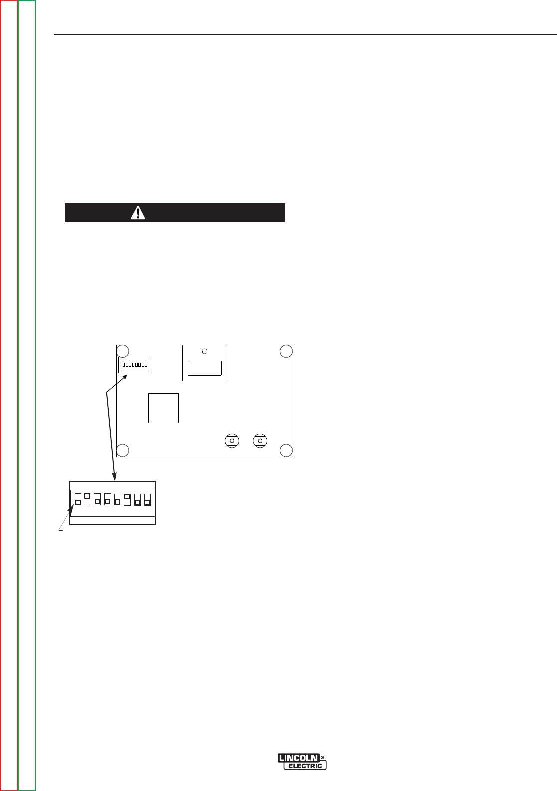
B-9
OPERATION
B-9
INTERNAL SET UP CONTROLS
Precision TIG 275 models which have an Advanced
Panel (K1829-1) option installed* have the following
additional control features which are set up using the
DIP Switch (S1) provided on the internal panel of this
option.
Access to this internal panel is obtained by removing
the two screws securing the top corners of the
Precision TIG front control panel and swinging the con-
trol panel down to reveal the panel mounted on the sur-
face of the Precision TIG Control board:
• THE CONTROL BOARDS CONTAIN STATIC SEN-
SITIVE COMPONENTS
• To avoid possible damage to these components
be sure to ground yourself by touching the
machineʼs sheet metal while handling or making
settings on the internal control box components.
------------------------------------------------------------------------
PRECISION TIG ADVANCED PANEL
(Internal Panel)
DIP SWITCH POSITIONS (FACTORY SETTINGS)
STICK WELDING FEATURES
The following DIP switch feature selections function
only when the Precision TIG is set to Stick mode. (See
Item 3):
• Switch #6 Hot Start Level (codes below 11000) –
Provides an extra output "boost" pulse at the arc
strike to enhance arc starting. This is factory set for
a level (about 50% extra) which is usually good for
most stick welding applications
ON – Hot Start level is used (as shipped).
OFF – No Hot Start.
• Switch #7 Arc Force Level(codes below 11000)–
Prevents "stubbing" of the electrode by providing
extra output current if the arc voltage drops below
the level required to sustain the welding arc. High
(+65%) and Low (+12%) factory set levels are
selectable which are good for most stick welding
applications.
ON – Higher for a "crisper" arc, often desired for 6010
type electrodes.
OFF – Lower Arc Force (as shipped) for a "softer" arc
with 7018 or general type electrodes.
• Switch #6 & #7 - Not functional on codes
above 11000 - See item 7a for
adjustment of Hot Start and
Arc Force
• Switch #8 - (NOT CURRENTLY FUNCTIONAL)
TIG WELDING FEATURES
The following DIP switch feature selections function
only when the Precision TIG is set to TIG mode (See
Item 3):
• Switch #1 Preflow/Postflow Time Extension*
(See Item 9)
ON – Doubles the time ranges.
OFF – Standard time ranges (as shipped).
• Switch #2 2-Step Trigger Restart Feature (See
Figure B.3)
ON – Restart Enabled (as shipped).
OFF – Restart Disabled.
• Switch #3 4-Step Trigger Restart Feature (See
Figure B.4)
ON – Restart Enabled.
OFF – Restart Disabled (as shipped)
• Switch #4 (NOT CURRENTLY FUNCTIONAL)
• Switch #5 Crater-Fill Level (See Item 7)
ON - Level is minimum rating of the machine (2A)
OFF – Level (as shipped) is Minimum Output setting
(same as Start level).
* The Preflow/Postflow Time doubling feature can also be selected
on Precision TIG 275 models without the Advanced Panel by
accessing the Control board in the control box per above instruc-
tions, then disconnecting the jumper terminals attached to the
jumper plug connected to receptacle J3 of the Control board.
(Refer to Machine Wiring Diagram.)
PRECISION TIG 275
CAUTION
HOT START
ARC FORCE
^ ON
1 2 3 4 5 6 7
DIP SWITCH (S1)
S F
ON
OFF
12 3 456 78
Return to Section TOC Return to Section TOC Return to Section TOC Return to Section TOC
Return to Master TOC Return to Master TOC Return to Master TOC Return to Master TOC
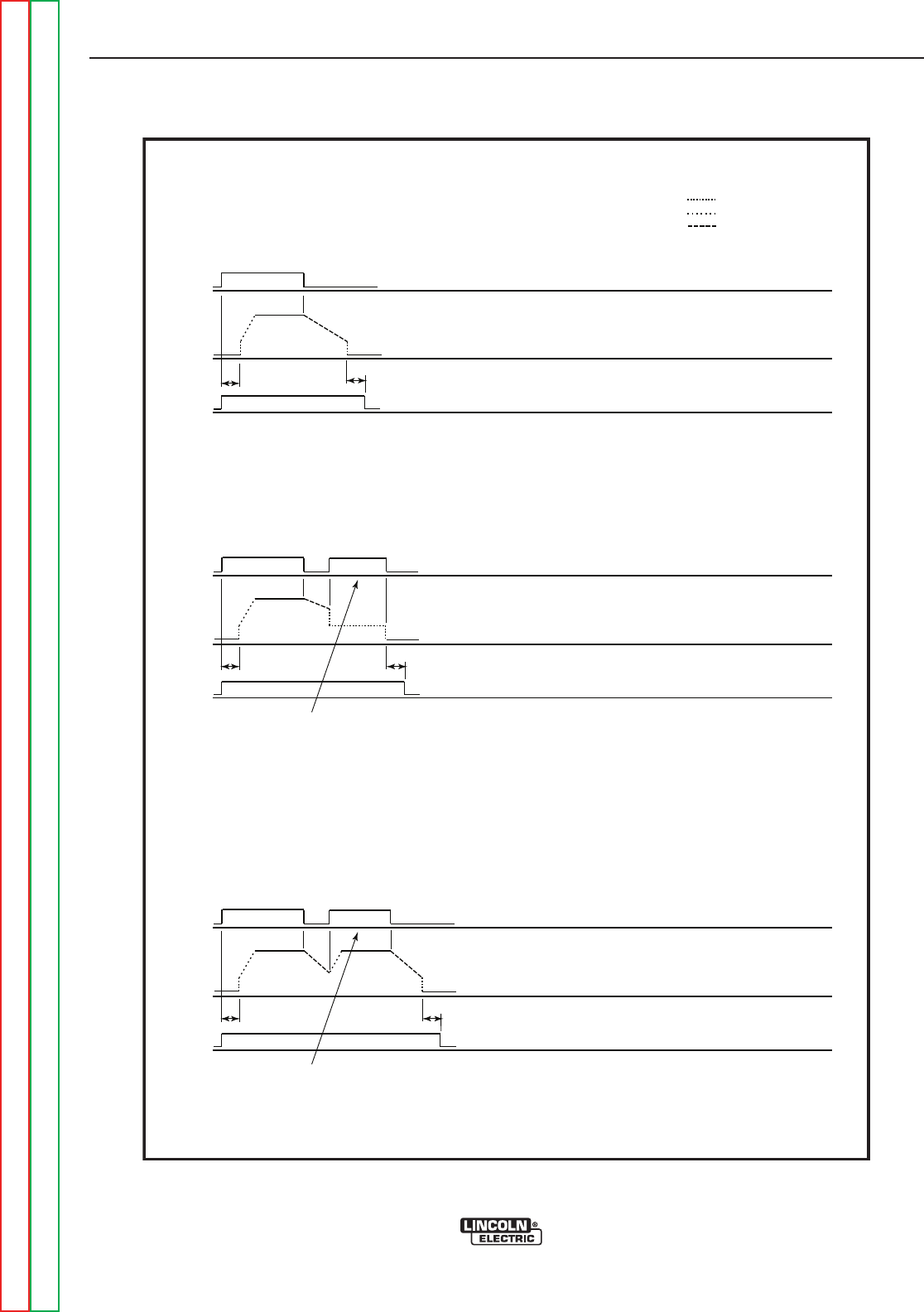
B-10
OPERATION
B-10
PRECISION TIG 275
Return to Section TOC Return to Section TOC Return to Section TOC Return to Section TOC
Return to Master TOC Return to Master TOC Return to Master TOC Return to Master TOC
FIGURE B.3
2 Step Trigger Modes
2 Step - Restart Disabled
2 Step - Restart Enabled
Torch
Button
Output
Current
Gas
Pre-Flow Post Flow
Normal Sequence
Torch
Button
Output
Current
Gas
Pre-Flow Post Flow
START/CRATER CURRENT
UP-SLOPE
DOWN-SLOPE
(With DIP Switch #2 OFF)
(With DIP Switch #2 ON. As Shipped)
Actuate the trigger a second
time, during down-slope, to
immediately end down-slope.
Hold the trigger to maintain
crater current.
Torch
Button
Output
Current
Gas
Pre-Flow Post Flow
Actuate the trigger a second
time, during down-slope, to
activate up-slope and restart.
2 Step.eps
12-17-07
JRH
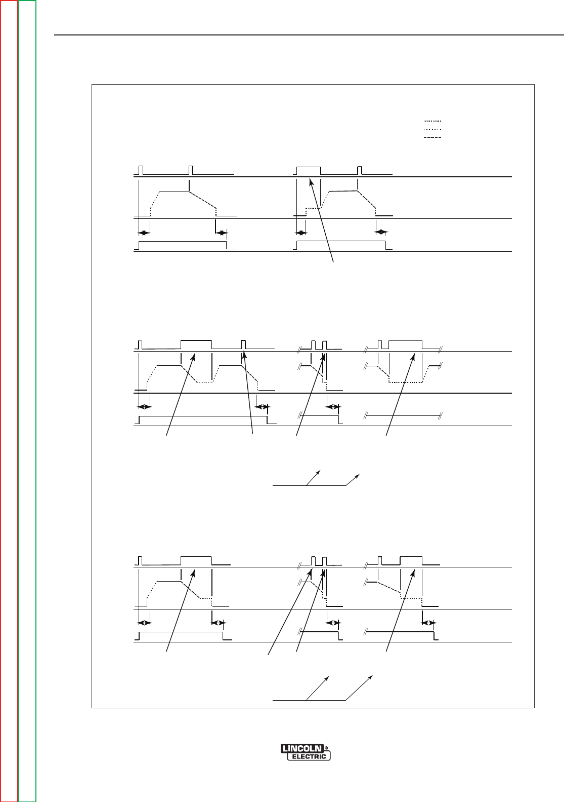
B-11
OPERATION
B-11
PRECISION TIG 275
Return to Section TOC Return to Section TOC Return to Section TOC Return to Section TOC
Return to Master TOC Return to Master TOC Return to Master TOC Return to Master TOC
FIGURE B.4
4 Step Trigger Modes
4 Step - Restart Enabled
4 Step - Restart Disabled
Torch
Button
Output
Current
Gas
Pre-Flow Pre-Flow
Post Flow Post Flow
Normal Sequence
Torch
Button
Output
Current
Gas
Pre-Flow Post Flow
START/CRATER CURRENT
UP-SLOPE
DOWN-SLOPE
(With DIP Switch #3 ON)
(With DIP Switch #3 OFF. As Shipped)
Post Flow
Hold the second trigger
pull for more than 1
second to activate the
restart function. When the
trigger is released
up-slope will occur.
Actuate the trigger
holding it less than 1
second, to begin
normal down-slope.
The following two
options are available
during the normal
down-slope period.
Actuate the trigger
again, during
down-slope, to
immediately end
down-slope and stop.
Or actuate and hold the trigger,
during down-slope, to immediately
end down-slope and maintain
crater current. Hold the trigger for
more than 1 second to activate the
restart function. When the trigger
is released up-slope will occur.
Hold the first trigger pull to maintain
the starting current and delay
up-slope.
Torch
Button
Output
Current
Gas
4 Step.eps
12-17-07
JRH
Pre-Flow Post Flow Post Flow Post Flow
Hold the second trigger
pull for more than 1
second to maintain
crater current before
stopping.
Actuate the trigger
holding it less than 1
second, to begin
normal down-slope.
The following two
options are available
during the normal
down-slope period.
Actuate the trigger a third
time, during down-slope, to
immediately end down-slope
and stop.
Or actuate the trigger a third time,
during down-slope, to immediately
end down-slope. Hold the third trigger
pull to maintain crater current.
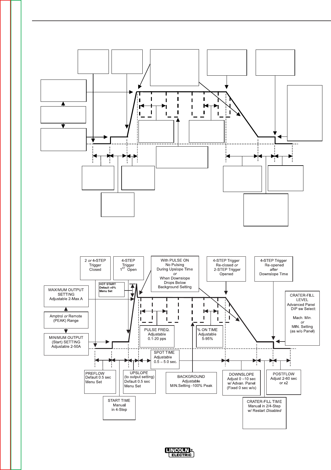
B-12
OPERATION
B-12
PRECISION TIG 275
Return to Section TOC Return to Section TOC Return to Section TOC Return to Section TOC
Return to Master TOC Return to Master TOC Return to Master TOC Return to Master TOC
PREFLOW
Fixed 0.5 sec
or x2
START TIME
Manual
in 4-Step
UPSLOPE
Fixed<0.5 sec
w/o Amptrol
MINIMUM OUTPUT
(Start) SETTING
Adjustable 2-50A
MAXIMUM OUTPUT
SETTING
Adjustable 2-Max.A
Amptrol or Remote
(PEAK) Range
2 or 4-STEP
Trigger
Closed
4-STEP
Trigger
1ST Open
4-STEP Trigger
Re-closed or
2-STEP Trigger
Opened
4-STEP Trigger
Re-opened
after
Downslope Time
DOWNSLOPE
Adjust 0 –10 sec
w/ Advan. Panel
(Fixed 0 sec w/o)
POSTFLOW
Adjust 2-60 sec
or x2
CRATER-FILL
LEVEL
Advanced
Panel Select:
Mach. Min.
or
MIN. Setting
(as w/o Panel)
With PULSE ON
No Pulsing
During Upslope Time
or
When Downslope
Drops Below
Background Setting
% ON TIME
Adjustable
5-95%
PULSE FREQ.
Adjustable
0.1-20 pps
BACKGROUND
Adjustable
MIN.Setting -100% Peak
CRATER-FILL TIME
Manual in 2/4-Step
w/ Restart Disabled
TIG WELD CYCLE CHART
CCOODDEESS BBEELLOOWW 1111000000 ((KK11882299--11))
CCOODDEESS AABBOOVVEE 1111000000 ((KK22662211--11))
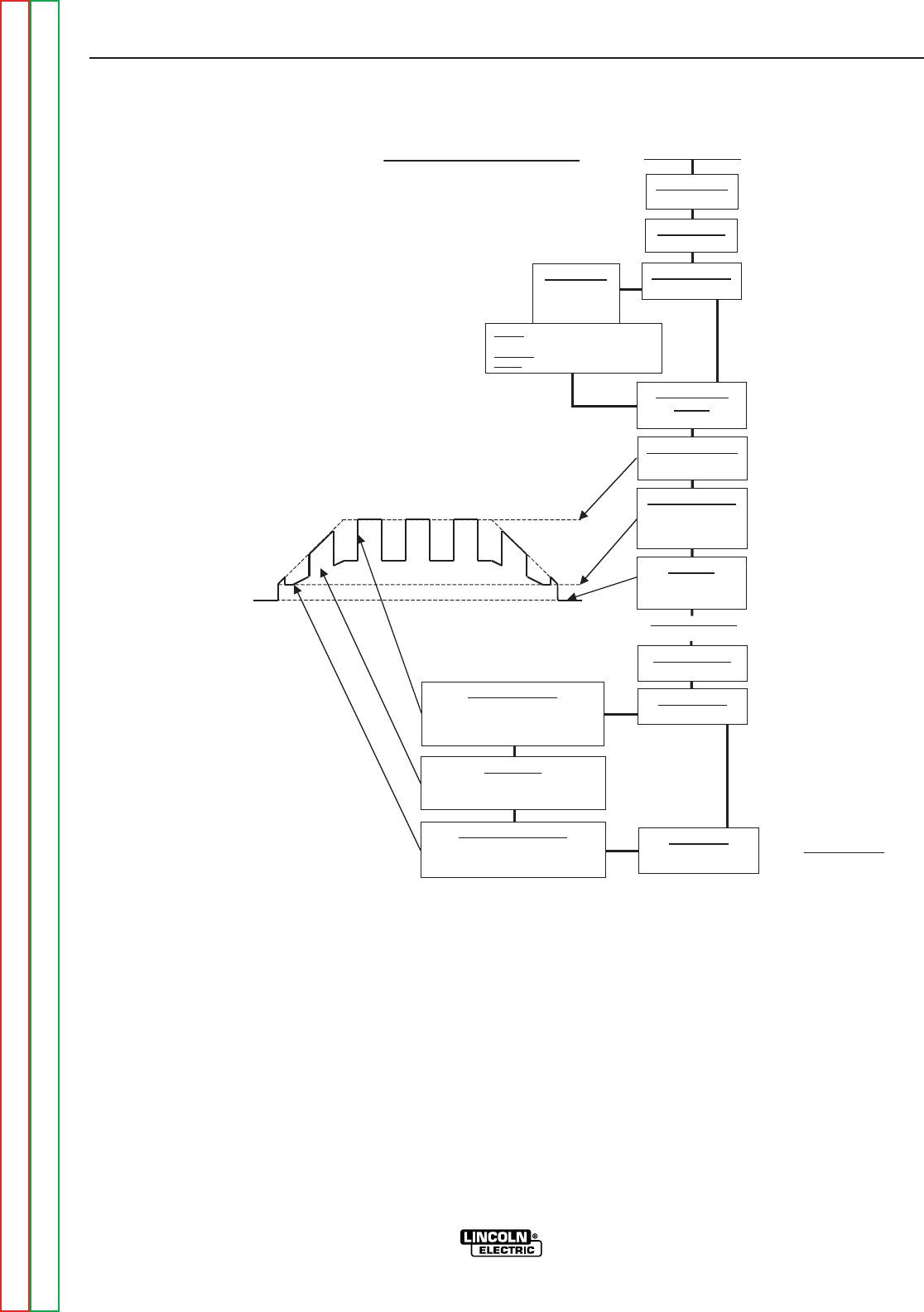
B-13
OPERATION
B-13
PRECISION TIG 275
FIGURE B.6
Return to Section TOC Return to Section TOC Return to Section TOC Return to Section TOC
Return to Master TOC Return to Master TOC Return to Master TOC Return to Master TOC
Max. to Min.
Amptrol
Min. to Max.
Amptrol
Setup for TIG Amptrol Welding
Advanced Panel
(If used)
Standard Controls
Power Switch
ON
Polarity Switch
AC or DC-
Mode Switch
TIG
AC Balance
AUTO
or
Set:
More + for alum. oxide “Cleaning“
w/o “spitting”or“wetting“ loss.
Balanced for equal + and - current.
More - for higher “Penetration“.
Local/Remote
Switch
REMOTE
Trigger Switch
2-STEP
Pulse Switch
ON or OFF
Pulse Frequency
4-6 pps is a typical initial setting.
Set for bead shape and travel speed:
Higher for thinner plate and faster travel.
Lower for thicker plate and slower travel.
% On Time
40-60% is a typical initial setting.
Set for total heat of Peak current:
Lower reduces distortion and burn-thru.
Background Current
40-60% is a typical initial setting.
Set as low as will maintain a pulse arc
(Will not drop below Min.Output setting.)
Downslope
ZERO
For no arc-out delay.
Minimum Output
Press Display switch
and Set to desired min.
Amptrol (Start/Crater)
output level.
Postflow
Set as low as required.
Higher for larger
tungsten and current.
Maximum Output
Set to desired max.
Amptrol output level.
AAddvvaanncceedd PPaanneell
Controls
SETUP GUIDELINES FOR TIG WELDING
WITH AN AMPTROL
Both the Hand and Foot Amptrols work in a similar
manner. They are meant to be used for remote current
control for TIG welding using the machineʼs 2-Step trig-
ger mode (See Item 12).
The Amptrol is capable of controlling the output of the
Precision TIG over the range between the level preset
by the Minimum Output control when the Amptrol is at
its inactivated state, and the level preset by the
Maximum Output control when the Amptrol is at fully-
activated state.
It is important to note that even with the Precision TIGʼs
new MicroStartTM Technology, some tungsten may be
difficult to start at the low (2 amps) minimum rating of
the machine. Rather than guessing where to depress
the Amptrol to start the arc reliably, the Minimum
Output control allows presetting the exact level, so reli-
able starts, as well as minimum crater-fill levels, can be
consistently obtained at the minimum Amptrol (inacti-
vated ) state. FIGURE B.6 shows Precision TIG setup
for TIG welding with an Amptrol.
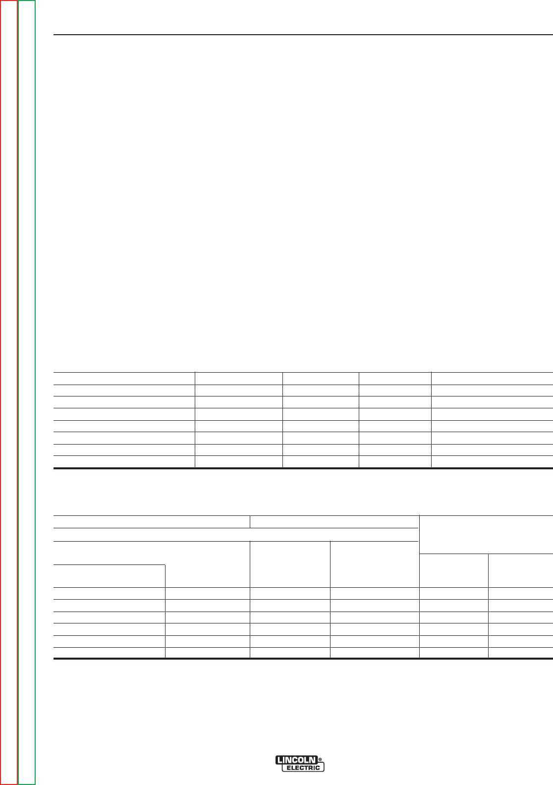
B-14
OPERATION
B-14
PRECISION TIG 275
Return to Section TOC Return to Section TOC Return to Section TOC Return to Section TOC
Return to Master TOC Return to Master TOC Return to Master TOC Return to Master TOC
RECOMMENDED ELECTRODE AMPERAGE RANGES - PRECISION TIG 275
SMAW Process
ELECTRODE POLARITY 3/32" 1/8" 5/32"
Fleetweld 5P, Fleetweld 5P+ DC+ 40 - 70 75 - 130 90 - 175
Fleetweld 180 DC+ 40 - 80 55 - 110 105 - 135
Fleetweld 37 DC+ 70 - 95 100 - 135 145 - 180
Fleetweld 47 DC- 75 - 95 100 - 145 135 - 200
Jet-LH MR DC+ 85 - 110 110 - 160 130 - 220
Blue Max Stainless DC+ 40 - 80 75 - 110 95 - 110
Red Baron Stainless DC+ 40 - 70 60 - 100 90 - 140
Mild steel procedures are based on recommended procedures listed in C2.10 8/94 and the maximum rating of the PRECISION TIG 275
Excaliber 7018 procedures are based on Jet-LH 78 MR
Blue Max procedures are based on C6.1 6/95
Red Baron Procedure are based on ES-503 10/93
GTAW Process
Electrode Polarity DC- AC* Approximate Argon
Electrode Tip Preparation Sharpened Balled Gas Flow Rate
Electrode Type EWZr C.F.H. (l/min.)
EWTh-1, EWCe-2 EWTh-1, EWTh-2
EWTh-2, EWLa-1 EWP EWCe-2, EWLa-1 Stainless
Electrode Size (in.) EWG EWG Aluminum Steel
.010 Up to 15 A. Up to 15 A. Up to 15 A. 3-8 (2-4) 3-8 (2-4)
.020 Up to 15 A. 10 to 15 A. 5 to 20 A. 5-10 (3-5) 5-10 (3-5)
.040 Up to 80 A. 20 to 30 A. 20 to 60 A. 5-10 (3-5) 5-10 (3-5)
1/16 Up to 150 A. 30 to 80 A. 60 to 120 A. 5-10 (3-5) 9-13 (4-6)
3/32 Up to MAX. A. 60 to 130 A. 100 to 180 A. 13-17 (6-8) 11-15 (5-7)
1/8 X 100 to 180 A. 160 to 250 A. 15-23 (7-11) 11-15 (5-7)
Tungsten electrodes are classified as follows by the American Welding Society (AWS):
Pure .........................................EWP...........green
+1% Thoria ..............................EWTh-1......yellow
+2% Thoria ..............................EWTh-2......red
+2% Ceria................................EWCe-2 .....orange
+1.5% Lanthana ......................EWLa-1 ......black
+0.15 to 0.40% Zirconia ..........EWZr..........brown
Ceriated Tungsten is now widely accepted as a substitute for 2% Thoriated Tungsten in AC and DC applications.
Balanced Wave, Unbalanced Wave requires derating of the electrode.
MAKING A TIG WELD WITH AN AMPTROL
1. Install welding equipment per Section A-5.
2. Setup controls per Section B-9.
3. Turn on the shielding gas supply, and torch coolant
input supply (if used).
Note: The Precision TIG Under-Cooler (or Water
Solenoid connected to the Cooler receptacle) runs with
the Fan-As-Needed machine cooling fan (See
Maintenance Section D), so the cooler fan and water
pump will also not run continuously in idle, but will run
while welding.
4. With the torch held safely away from everything,
close the Arc Start Switch of the Amptrol and set the
gas flow meter. Then open the switch. The welder
is now ready for welding.
5. Position the tungsten electrode at the start of the
weld at a 65° to 75° angle with the horizontal, in the
direction of pushing travel, so that the electrode is
approximately 1/8" (4 mm) above the work piece.
Close the arc start switch. This opens the gas valve
to automatically purge air from the hose and torch,
then shields the arc strike area. After the 0.5 sec-
ond preflow time, the high frequency becomes
available to strike the arc. When the arc strikes the
torch coolant (if used) starts to flow. Also, if welding
DC- TIG, the high frequency shuts off just after the
arc strikes.
6. Hold the arc start switch closed at minimum Amptrol
Start level (See Section B-10) until an arc is estab-
lished, then increase the output to the desired weld-
ing level and push the torch in the direction of trav-
el.
7. At the end of the weld, decrease the Amptrol output
to the crater-fill level before releasing the arc start
switch to start the Postflow time. Hold the torch gas
shielding over the solidifying weld crater while post-
flow time expires and the gas valve reopens. The
torch coolant (if used) continues to flow for up to 8
minutes after the arc goes out (with the Fan-As-
Needed feature) to assure torch cooling.
• Repeat steps 5 through 7 to make another weld.

C-1C-1
PRECISION TIG 275
TABLE OF CONTENTS
- ACCESSORIES -
Accessories...........................................................................................................................Section C
Optional Equipment for Codes Below 11000..............................................................................C-2
Optional Equipment for Codes Above 11000..............................................................................C-3
Return to Master TOC Return to Master TOC Return to Master TOC Return to Master TOC

C-2
ACCESSORIES FOR CODES BELOW 11000
C-2
PRECISION TIG 275
Return to Section TOC Return to Section TOC Return to Section TOC Return to Section TOC
Return to Master TOC Return to Master TOC Return to Master TOC Return to Master TOC
OPTIONAL EQUIPMENT
FACTORY INSTALLED OPTIONS
The basic Precision TIG 275 machine is factory
equipped with:
• A 3/8" Adapter (S20403-4) for air cooled torch con-
nection of a PTA-9 or PTA-17.
Accessories that are factory installed with the
Domestic model (K1826-1) to make up the Domestic
Welding Package (K1825-1) include:
• K1828-1 Under-Cooler Cart
• 3100211 Harris Argon Flow Regulator with 10ʼ
Hose.
• K870 Foot Amptrol
• K1784-4 25ʼ PTW-20 water-cooled TIG Torch
• K918-2 Zippered Torch Cover
• KP510 Parts Kit for Torch
• K2150-1 Work Lead Assembly
See below for more detailed descriptions.
FIELD INSTALLED OPTIONS
The following Options/Accessories are available for the
Precision TIG 275 and are installed per instructions in
this manual and / or provided in the package:
• K1829-1 Precision TIG Advanced Control Panel
Provides 2/4-step trigger with adjustable Pulser con-
trols and Down slope timer for TIG welding. Also
includes adjustable Hot Start and Arc Force internal
panel controls for Stick welding, and other user
selectable features.
• K1828-1 Under-Cooler Cart
Includes a "cooler-in-a-drawer" with hoses and a
lockable storage drawer on a dual bottle undercar-
riage (see below).
• K1869-1 Undercarriage
Includes a dual bottle rack with chain and an under-
carriage with 5" front casters,10" rear wheels and a
handle.
• K1830-1 Water Solenoid Kit
Provides for stopping flow of external water supply.
Connects to coolant inlet and cooler receptacle of
Precision TIG.
(Cannot be used with a water cooler.)
• K870 Foot Amptrol
Single pedal foot activation of arc start switch and
output control, with 25ʼ plug cable.
• K870-1 Start Pedal Foot Amptrol
Independent start pedal on control pedal provides
two-stage foot action to easily feel start switch clo-
sure at minimum output level for enhanced arc start
and crater-fill control. Provided with adjustable, or
removable , heel stop and 25ʼ plug cable.(Refer to
Figure B.5)
• K963-3 Hand Amptrol
Fastens to torch for convenient thumb activation of
arc start switch and output control, with 25ʼ plug
cable:
K963-1 is for PTA-9,-17 and PTW-20 Torches.
K963-2 is for PTA-26 and PTW-18 Torches.
• K814 Arc Start Switch
Needed for TIG welding without an Amptrol. Includes
25ʼ plug cable, and attaches to torch for convenient
finger control.
• K1831-1 Power Factor Capacitor Kit
Used when welding at higher output currents to
reduce input current and help keep electricity costs
to a minimum.
• Magnum® PTA and PTW Series Torches
All Air Cooled or Water-Cooled Magnum® TIG
Torches may be used with the PRECISION TIG 275.
Connection adapters are only required for Air-Cooled
Torches (Refer to Diagrams on A-7):
K2166-1 7/8” Torch Connector for PTA-26 (one
piece)
K2166-2 1/2” stud Connector for PTA Torch (two-
piece).
K2166-3 3/8” TIG Torch Connector for PTA-9,-17
(one piece). (Included as S20403-4 with Precision
TIG models.)
• 3100211 Harris Argon Flow Regulator (Includes 10ʼ
hose.)
• K2150-1 Work Lead Assembly
15ft. 2/0 cable with 1/2" stud lug and work clamp.

C-3
ACCESSORIES FOR CODES ABOVE 11000
C-3
PRECISION TIG 275
Return to Section TOC Return to Section TOC Return to Section TOC Return to Section TOC
Return to Master TOC Return to Master TOC Return to Master TOC Return to Master TOC
OPTIONAL EQUIPMENT
FACTORY INSTALLED OPTIONS
The basic Precision TIG 275 machine is factory
equipped with:
• A 3/8" Adapter (S20403-4) for air cooled torch con-
nection of a PTA-9 or PTA-17.
Accessories that are factory installed with the
Domestic model (K1826-1) to make up the Domestic
Welding Package (K1825-1) include:
• K1828-1 Under-Cooler Cart
• 3100211 Harris Argon Flow Regulator with 10ʼ
Hose.
• K870 Foot Amptrol
• K1784-4 25ʼ PTW-20 water-cooled TIG Torch
• K918-2 Zippered Torch Cover
• KP510 Parts Kit for Torch
• K2150-1 Work Lead Assembly
See below for more detailed descriptions.
FIELD INSTALLED OPTIONS
The following Options/Accessories are available for the
Precision TIG 275 and are installed per instructions in
this manual and / or provided in the package:
• K2621-1 Precision TIG Advanced Control Panel
Provides 2/4-step trigger with adjustable Pulser
controls and Down slope timer for TIG welding. Also
includes adjustable Hot Start and Arc Force internal
panel controls for Stick welding, and other user
selectable features.
• K1828-1 Under-Cooler Cart
Includes a "cooler-in-a-drawer" with hoses and a
lockable storage drawer on a dual bottle undercar-
riage (see below).
• K1869-1 Undercarriage
Includes a dual bottle rack with chain and an under-
carriage with 5" front casters,10" rear wheels and a
handle.
• K1830-1 Water Solenoid Kit
Provides for stopping flow of external water supply.
Connects to coolant inlet and cooler receptacle of
Precision TIG.
(Cannot be used with a water cooler.)
• K870 Foot Amptrol
Single pedal foot activation of arc start switch and
output control, with 25ʼ plug cable.
• K963-3-3 Hand Amptrol
Fastens to torch for convenient thumb activation of
arc start switch and output control, with 25ʼ plug
cable:
• K814 Arc Start Switch
Needed for TIG welding without an Amptrol. Includes
25ʼ plug cable, and attaches to torch for convenient
finger control.
• K1831-1 Power Factor Capacitor Kit
Used when welding at higher output currents to
reduce input current and help keep electricity costs
to a minimum.
• Magnum® PTA and PTW Series Torches
All Air Cooled or Water-Cooled Magnum® TIG
Torches may be used with the PRECISION TIG 275.
Connection adapters are only required for Air-Cooled
Torches (Refer to Diagrams on A-7):
K2166-1 7/8” Torch Connector for PTA-26 (one
piece)
K2166-2 1/2” stud Connector for PTA Torch (two-
piece).
K2166-3 3/8” TIG Torch Connector for PTA-9,-17
(one piece). (Included as S20403-4 with Precision
TIG models.)
• 3100211 Harris Argon Flow Regulator (Includes 10ʼ
hose.)
• K2150-1 Work Lead Assembly
15ft. 2/0 cable with 1/2" stud lug and work clamp.


D-1D-1
PRECISION TIG 275
Return to Master TOC Return to Master TOC Return to Master TOC Return to Master TOC
TABLE OF CONTENTS
-MAINTENANCE-
Maintenance ..........................................................................................................................Section D
Safety Precautions......................................................................................................................D-2
Routine and Periodic Maintenance.............................................................................................D-2
Overload Protection ....................................................................................................................D-2
Fan As Needed (F.A.N.)..............................................................................................................D-2
Service Procedures.....................................................................................................................D-3
Component Location and Access ...............................................................................................D-3
Spark Gap Adjustment ................................................................................................................D-3
Major Component Location.........................................................................................................D-4

D-2
MAINTENANCE
D-2
PRECISION TIG 275
ELECTRIC SHOCK can kill.
• Only qualified personnel should
perform this maintenance.
• Turn the input power OFF at the
disconnect switch or fuse box
before working on this
equipment.
• Do not touch electrically hot
parts.
To avoid receiving a high frequency shock, keep the
TIG torch and cables in good condition.
Very little routine maintenance is necessary to keep
your Precision TIG 275 running in top condition. No
specific schedule can be set for performing the follow-
ing items; factors such as hours of usage and machine
environment should be considered when establishing
a maintenance schedule.
• Periodically blow out dust and dirt which may accu-
mulate within the welder using an air stream.
• Inspect welder output and control cables for fraying,
cuts, and bare spots.
• Inspect the spark gap at regular intervals to maintain
the recommended spacing. See the Service
Procedures (See Service Procedures in this
Section) for complete information on spark gap set-
tings.
• The fan motor has sealed ball bearings which
require no maintenance.
SAFETY PRECAUTIONS
ROUTINE AND PERIODIC MAINTENANCE
WARNING
WARNING
OVERLOAD PROTECTION
FAN-AS-NEEDED (F.A.N.)
The Precision TIG 275 has the F.A.N. circuit feature,
which means the cooling fan will operate only while
welding; then for about 8 minutes after welding has
stopped to assure proper machine cooling. This helps
reduce the amount of dust and dirt drawn into the
machine with the cooling air. The cooling fan will oper-
ate briefly when the machine power is initially turned
on, and continuously while the yellow Thermal
Shutdown Light is lit (see Thermostatic Protection).
THERMOSTATIC PROTECTION
This welder has thermostatic protection from excessive
duty cycles, overloads, loss of cooling, and excessive
ambient temperatures. When the welder is subjected
to an overload, or inadequate cooling, the primary coil
thermostat and/or secondary coil thermostat will open.
This condition will be indicated by the illumination of
the yellow Thermal Shutdown Light on the front panel
(see Item 10 in Section B). The fan will continue to run
to cool the power source. Postflow occurs when TIG
welding is shut down, but no welding is possible until
the machine is allowed to cool and the yellow Thermal
Shutdown Light goes out.
NO ARC PROTECTION
The machine outputs (Background / OCV, gas and HF)
will be shutdown, if the trigger is closed without weld-
ing for 15 seconds to protect the Background resistor
from overheating with F.A.N. cooling off, as well as to
conserve on gas waste.
AUXILIARY POWER CIRCUIT BREAKER
The 115vac auxiliary circuits and rear receptacle (see
Section A Auxiliary Power Connections) are protected
from overloads by a 15 amp circuit breaker, located
above the receptacle. If the breaker trips its button
pops out exposing a red ring. When the circuit breaker
cools the button can be reset by pressing it back in.
Note: When the breaker trips not only will the recepta-
cleʼs auxiliary and cooler power be interrupted, but so
will the power to the shielding gas solenoid and
machine cooling fan.
The Export models also include a 5 amp circuit break-
er, located on the opposite side of the upper case back,
for protection of the 220 VAC Schuko type cooler
receptacle.
Return to Section TOC Return to Section TOC Return to Section TOC Return to Section TOC
Return to Master TOC Return to Master TOC Return to Master TOC Return to Master TOC
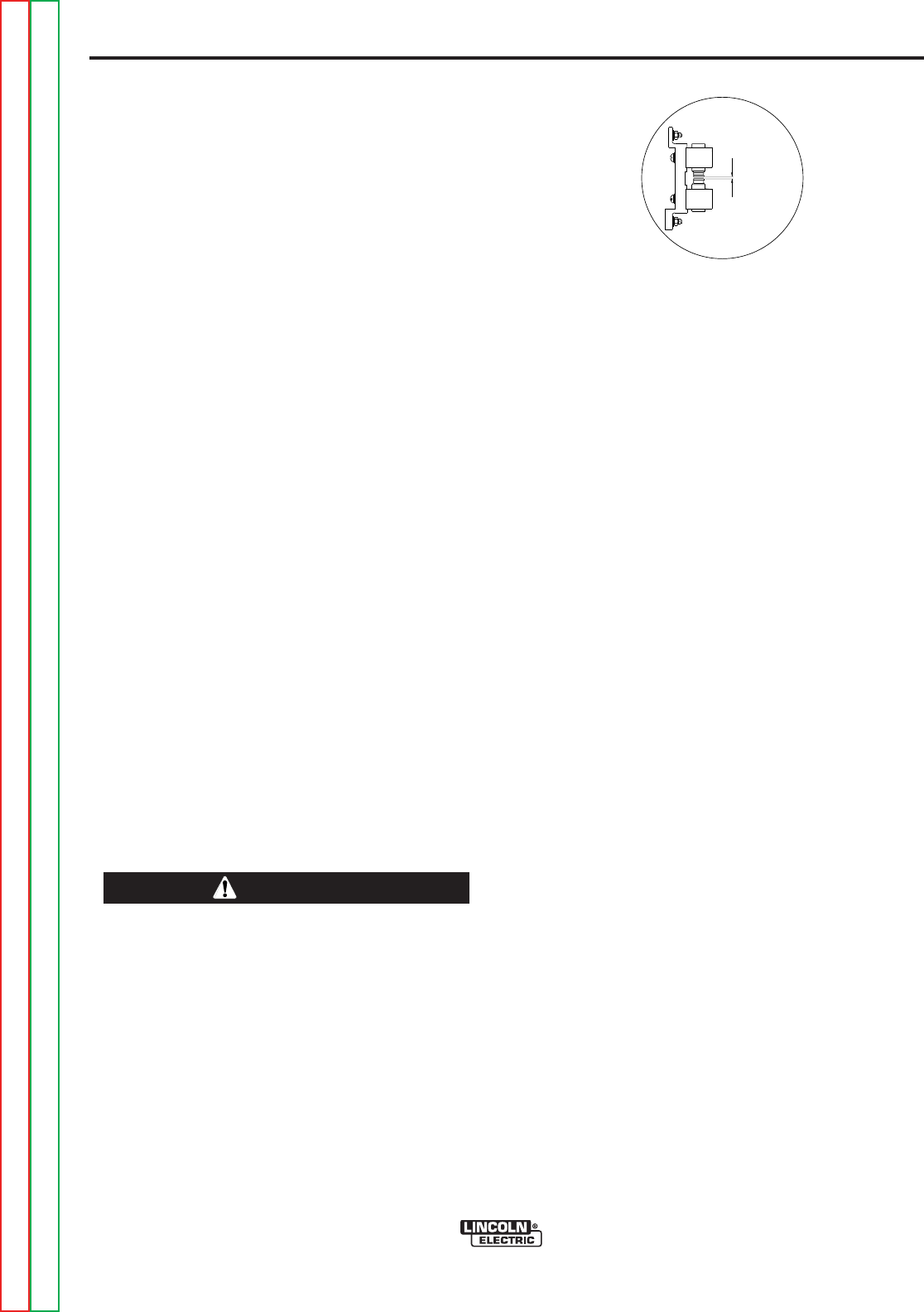
D-3
MAINTENANCE
D-3
SERVICE PROCEDURES
Operation of the Precision TIG should be trouble-free
for the life of the machine. Should a malfunction occur,
however, the following procedures will be useful to
trained service personnel with experience in repairing
arc welding equipment:
COMPONENT ACCESS
The following components are accessible for routine
set up and periodic service without requiring removal
of the case sides or roof:
• Input Reconnect Panel (refer Section A) is located
behind a removable panel on the rear of the left case
side. Remove the two screws (with a screwdriver or
a 3/8"/ 9.5mm hex driver) on the bottom corners of
this panel to remove it.
• Control Box components and PC Boards (refer
Section B-6) are located behind the front control
panel. Remove the two screws (with a screwdriver or
a 3/8"/ 9.5mm hex driver) on the top corners of this
panel to swing it down.
• Hi-Freq. Spark Gap Assembly (refer Spark Gap
Adjustment) is located behind a removable panel on
the rear of the right case side, under the torch box.
Remove the screw (with a screwdriver or a 3/8"/
9.5mm hex driver) on the bottom center of this panel
to remove it.
SPARK GAP ADJUSTMENT
The spark gap is set at the factory to a gap of 0.015
inches (0.4 mm) See Figure C.1. This setting is ade-
quate for most applications. Where less high frequen-
cy is desired, the setting can be reduced to 0.008 inch-
es (0.2 mm).
Use extreme caution when working with the high
frequency circuit. The high voltages developed can
be lethal. Turn the input power off using the dis-
connect switch or fuse box before working inside
the machine. This is particularly important when
working on the secondary circuit of the high volt-
age transformer (T3) because the output voltage is
dangerously high.
------------------------------------------------------------------------
Note: In highly dirty environments where there is an
abundance of conductive contaminants, use a low
pressure air stream or a firm piece of paper to clean
out the spark gap. Do not disturb the factory gap set-
ting.
To check the spark gap:
1. Turn the input power off per above.
2. Remove the access panel on the right case side
(See Component Access).
3. Check the spark gap spacing with a feeler gauge.
If adjustment is required:
1. Adjust the gap by loosening the Allen head screw
on one of the aluminum blocks, reset the gap and
tighten the screw in the new position.
If spark gap is correct:
1. Reinstall the access panel on the right case side.
UNDER-COOLER SERVICE
The required maintenance and service instructions for
the Under-Cooler are provided in the operatorʼs manu-
al (IM723) provided with the Under-Cooler Cart.
PRECISION TIG 275
Return to Section TOC Return to Section TOC Return to Section TOC Return to Section TOC
Return to Master TOC Return to Master TOC Return to Master TOC Return to Master TOC
.015 Spark Gap
FIGURE C.1 SPARK GAP
WARNING
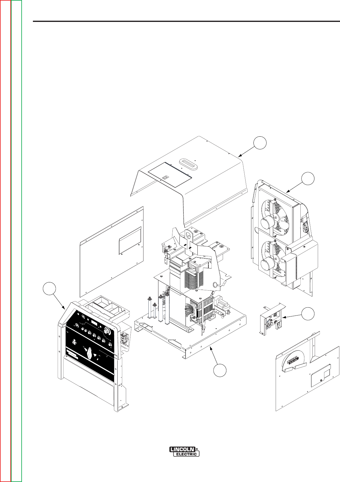
D-4
MAINTENANCE
D-4
PRECISION TIG 275
Return to Section TOC Return to Section TOC Return to Section TOC Return to Section TOC
Return to Master TOC Return to Master TOC Return to Master TOC Return to Master TOC
1. Case Front Assembly
2. Arc Starter and Bypass Assembly
3. Case Back Assembly
4. Center Assembly
5. Case Cover Assembly
REMO
REMOTE
TE
LOCAL
LOCAL
MAXIMUM
MAXIMUM
DISPLA
DISPLAYY
MINIMUM
MINIMUM
MODE
MODE
A
AC B
CBALANCE
ALANCEPOSTFLO
POSTFLOWW
DC
ON
OFF
POWER
AC
DC +
PRECISION TIGTM
375
THE LINCOLN ELECTRIC COMPANY CLEVELAND, OHIO USA
DO NOT SWITCH
WHILE WELDING
SQUARE WAVE POWER SOURCE
featuring ...MICRO START TM
TECHNOLOGY
~
WARNING
LINCOLN
ELECTRIC
!
3
5
4
1
2
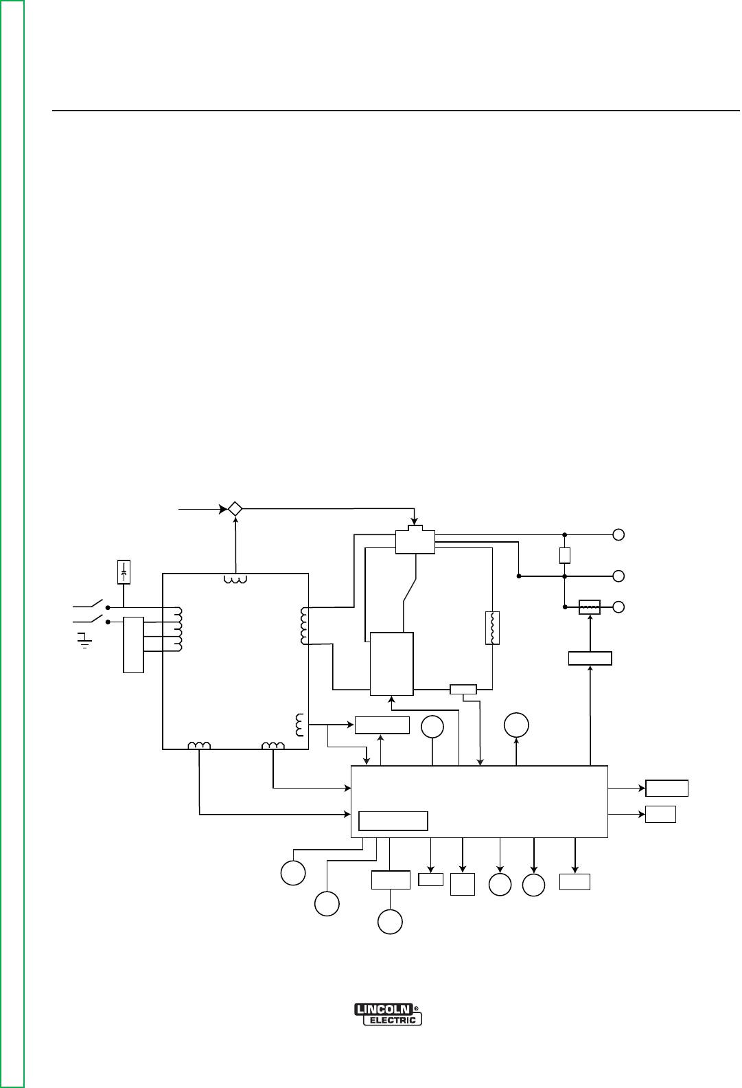
Return to Master TOC Return to Master TOC Return to Master TOC Return to Master TOC
E-1E-1
PRECISION TIG 275
Theory of Operation..............................................................................................................Section E
General Description ....................................................................................................................E-2
Input Power Circuit......................................................................................................................E-2
Output Rectification, Control Board and Feedback ....................................................................E-3
High Voltage/High Frequency Circuit ..........................................................................................E-4
DC Welding Output .....................................................................................................................E-5
AC Welding Output .....................................................................................................................E-6
SCR Operation............................................................................................................................E-7
Protective Circuits .......................................................................................................................E-8
Fan As Needed (F.A.N.)........................................................................................................E-8
Thermal Protection ...............................................................................................................E-8
Overload Protection ..............................................................................................................E-8
TABLE OF CONTENTS
-THEORY OF OPERATION SECTION-
POWER
SWITCH
RECONNECT
PANEL
OPTIONAL POWER
FACTOR
POLARITY
SWITCH
BYPASS BOARD
WORK
FRONT
ELECTRODE
REAR
ELECTRODE
78 VAC
X1
X2
AC
AC
DC
DC SHUNT
CHOKE
HIGH FREQUENCY
TRANSFORMER
HIGH VOLTAGE
TRANSFORMER
THERMOSTAT
115 VAC
115 VAC
115 VAC
FAN
GATE LEADS
FEEDBACK
GAS
SOLENOID
115 VAC
115 VAC
LED's
THERMOSTAT
20 VAC
20 VAC
CONTROL BOARD
BACKGROUND
CIRCUIT
FROM
CONTROL
BOARD
63.5 VAC
CORRECTION
CAPACITORS
REAR GANG
SCR
BRIDGE
ADVANCED CONTROL
PANEL RECEPTACLE
MINIMUM
OUTPUT
CONTROL
MAXIMUM
OUTPUT
CONTROL
PROTECTION
BOARD
REMOTE
RECEPTACLE
METER STICK
TIG
SWITCH
BALANCE
CONTROL
POST
FLOW
LOCAL/REMOTE
SWITCH
FIGURE E.1 – PRECISION TIG 275 BLOCK LOGIC DIAGRAM
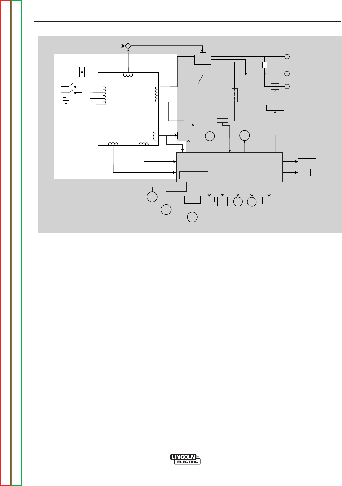
E-2E-2
PRECISION TIG 275
FIGURE E.2 – GENERAL DESCRIPTION AND INPUT POWER CIRCUIT
POWER
SWITCH
RECONNECT
PANEL
OPTIONAL POWER
FACTOR
POLARITY
SWITCH
BYPASS BOARD
WORK
FRONT
ELECTRODE
REAR
ELECTRODE
78 VAC
X1
X2
AC
AC
DC
DC SHUNT
CHOKE
HIGH FREQUENCY
TRANSFORMER
HIGH VOLTAGE
TRANSFORMER
THERMOSTAT
115 VAC
115 VAC
115 VAC
FAN
GATE LEADS
FEEDBACK
GAS
SOLENOID
115 VAC
115 VAC
LED's
THERMOSTAT
20 VAC
20 VAC
CONTROL BOARD
BACKGROUND
CIRCUIT
FROM
CONTROL
BOARD
63.5 VAC
CORRECTION
CAPACITORS
REAR GANG
SCR
BRIDGE
ADVANCED CONTROL
PANEL RECEPTACLE
MINIMUM
OUTPUT
CONTROL
MAXIMUM
OUTPUT
CONTROL
PROTECTION
BOARD
REMOTE
RECEPTACLE
METER STICK
TIG
SWITCH
BALANCE
CONTROL
POST
FLOW
LOCAL/REMOTE
SWITCH
GENERAL DESCRIPTION
The PRECISION TIG 275 is part of a new family of
industrial arc welding power sources able to provide
constant current and single range square wave AC/DC
Tig (GTAW) with new MicroStartTM Technology. It incor-
porates independent presettable minimum and maxi-
mum output control with built-in high frequency stabi-
lization for continuous AC Tig welding and reliable DC
Tig starting. The Precision TIG 275 also has AC/DC
stick (SMAW) capabilities. This new design includes
advanced features such as a digital meter, presettable
controls, auto balanceTM , fan as needed and timers for
fixed preflow and variable post flow of shielding gas. It
features a stick output terminal (front) and a universal
Tig torch connection box (rear) for simultaneous, but
separate, electrode outputs.
INPUT POWER CIRCUIT
The desired single-phase input power is connected to
the PRECISION TIG 275 through the power switch to
the reconnect panel located in the rear of the machine.
The machine can be configured for any one of three
input voltages (208 VAC, 230 VAC or 460 VAC) by con-
necting the jumper strap to the appropriate terminal on
the reconnect panel. When the input power switch is
turned “on,” the input voltage is applied directly to the
primary winding of the main transformer.
The main transformer changes the high voltage, low
current input power to a low voltage, high current out-
put available at the main secondary winding (X1 and
X2). This 78 VAC winding supplies power to the weld-
ing arc. In addition, four auxiliary windings are incor-
porated in the main transformer. The 115 VAC winding
supplies power to the 115 VAC receptacle. Through
the control board, it also powers the gas solenoid, the
high voltage transformer, and the cooling fan. The
cooling fan is activated only when welding current is
sensed. The 63.5 VAC winding provides power for the
DC background current. This circuit is active in the DC
TIG welding mode. The 20 VAC windings are included
in the main transformer assembly. The 20 VAC winding
is rectified on the control board and is used in the trig-
ger circuitry. The other 20 VAC winding is used by the
control board for phase detection. This AC voltage is
also rectified to several DC voltages and regulated to
+15 VDC and +5 VDC power supplies that operate the
circuitry on the control board.
NOTE: Unshaded areas of Block Logic Diagram are the subject of discussion.
Return to Section TOC Return to Section TOC Return to Section TOC Return to Section TOC
Return to Master TOC Return to Master TOC Return to Master TOC Return to Master TOC
THEORY OF OPERATION
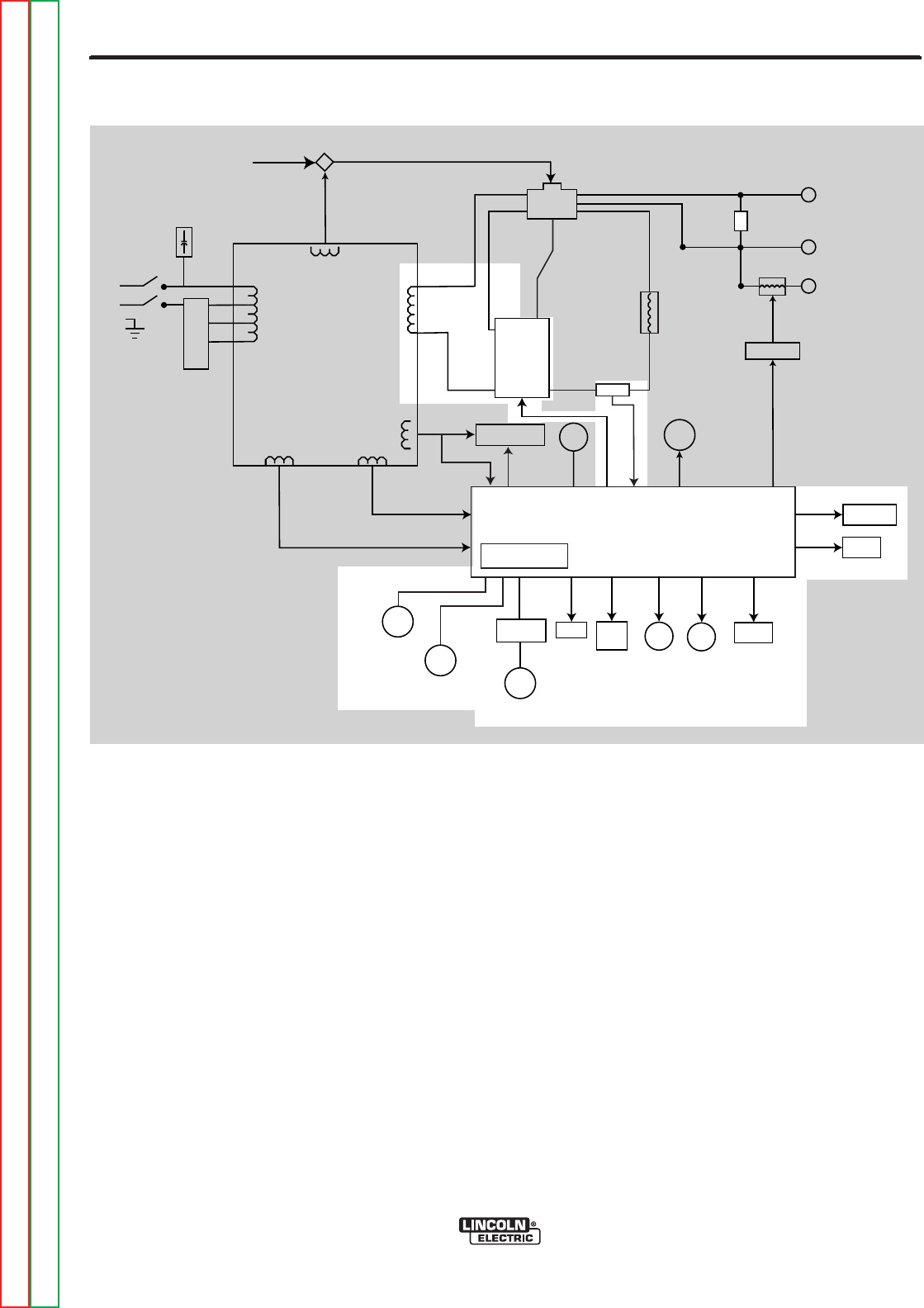
E-3E-3
PRECISION TIG 275
Return to Section TOC Return to Section TOC Return to Section TOC Return to Section TOC
Return to Master TOC Return to Master TOC Return to Master TOC Return to Master TOC
OUTPUT RECTIFICATION,
CONTROL BOARD AND FEEDBACK
The AC output from the main transformer secondary
is rectified and controlled through the SCR bridge.
Output current is sensed at the shunt as a low voltage
signal and fed back to the control board. The control
board senses the status and settings of the various
operator controls such as the Stick/TIG switch, the
output controls, the remote control receptacle, the
local/remote switch, the balance control and the post-
flow control. Circuitry on the control board evaluates
these commands, compares them to the feedback
information received from the shunt and sends the
appropriate gate firing signals to the output SCR
bridge. The control board regulates the firing of the
output SCRs, which control the output of the machine.
See SCR Operation.
The control board also monitors the thermostats and
controls the gas solenoid, the thermal light, the high
voltage transformer and the cooling fan. The optional
advanced control panel also plugs into and interfaces
with the control board.
THEORY OF OPERATION
FIGURE E.3 – OUTPUT RECTIFICATION, CONTROL BOARD AND FEEDBACK
POWER
SWITCH
RECONNECT
PANEL
OPTIONAL POWER
FACTOR
POLARITY
SWITCH
BYPASS BOARD
WORK
FRONT
ELECTRODE
REAR
ELECTRODE
78 VAC
X1
X2
AC
AC
DC
DC SHUNT
CHOKE
HIGH FREQUENCY
TRANSFORMER
HIGH VOLTAGE
TRANSFORMER
THERMOSTAT
115 VAC
115 VAC
115 VAC
FAN
GATE LEADS
FEEDBACK
GAS
SOLENOID
115 VAC
115 VAC
LED's
THERMOSTAT
20 VAC
20 VAC
CONTROL BOARD
BACKGROUND
CIRCUIT
FROM
CONTROL
BOARD
63.5 VAC
CORRECTION
CAPACITORS
REAR GANG
SCR
BRIDGE
ADVANCED CONTROL
PANEL RECEPTACLE
MINIMUM
OUTPUT
CONTROL
MAXIMUM
OUTPUT
CONTROL
PROTECTION
BOARD
REMOTE
RECEPTACLE
METER STICK
TIG
SWITCH
BALANCE
CONTROL
POST
FLOW
LOCAL/REMOTE
SWITCH
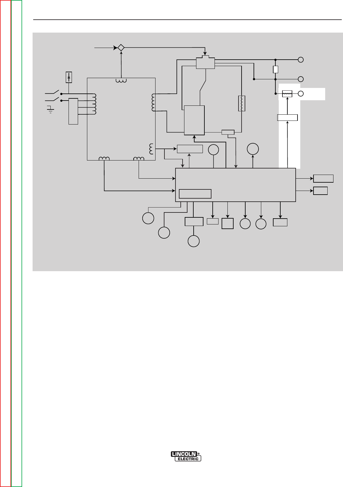
E-4E-4
PRECISION TIG 275
THEORY OF OPERATION
FIGURE E.4 – HIGH VOLTAGE / HIGH FREQUENCY CIRCUIT
POWER
SWITCH
RECONNECT
PANEL
OPTIONAL POWER
FACTOR
POLARITY
SWITCH
BYPASS BOARD
WORK
FRONT
ELECTRODE
REAR
ELECTRODE
78 VAC
X1
X2
AC
AC
DC
DC SHUNT
CHOKE
HIGH FREQUENCY
TRANSFORMER
HIGH VOLTAGE
TRANSFORMER
THERMOSTAT
115 VAC
115 VAC
115 VAC
FAN
GATE LEADS
FEEDBACK
GAS
SOLENOID
115 VAC
115 VAC
LED's
THERMOSTAT
20 VAC
20 VAC
CONTROL BOARD
BACKGROUND
CIRCUIT
FROM
CONTROL
BOARD
63.5 VAC
CORRECTION
CAPACITORS
REAR GANG
SCR
BRIDGE
ADVANCED CONTROL
PANEL RECEPTACLE
MINIMUM
OUTPUT
CONTROL
MAXIMUM
OUTPUT
CONTROL
PROTECTION
BOARD
REMOTE
RECEPTACLE
METER STICK
TIG
SWITCH
BALANCE
CONTROL
POST
FLOW
LOCAL/REMOTE
SWITCH
HIGH VOLTAGE/HIGH FREQUENCY
CIRCUIT
The control board passes the 115 VAC voltage to the
primary of the high voltage transformer. The secondary
of the high voltage transformer is coupled to a spark
gap generator and also to the primary winding of the
high frequency transformer. The secondary of the high
frequency transformer is in series with the rear elec-
trode output terminal. The high frequency “spark” is
present at the electrode terminal and is transferred to
the Tig torch.
NOTE: Unshaded areas of Block Logic Diagram are the subject of discussion.
Return to Section TOC Return to Section TOC Return to Section TOC Return to Section TOC
Return to Master TOC Return to Master TOC Return to Master TOC Return to Master TOC
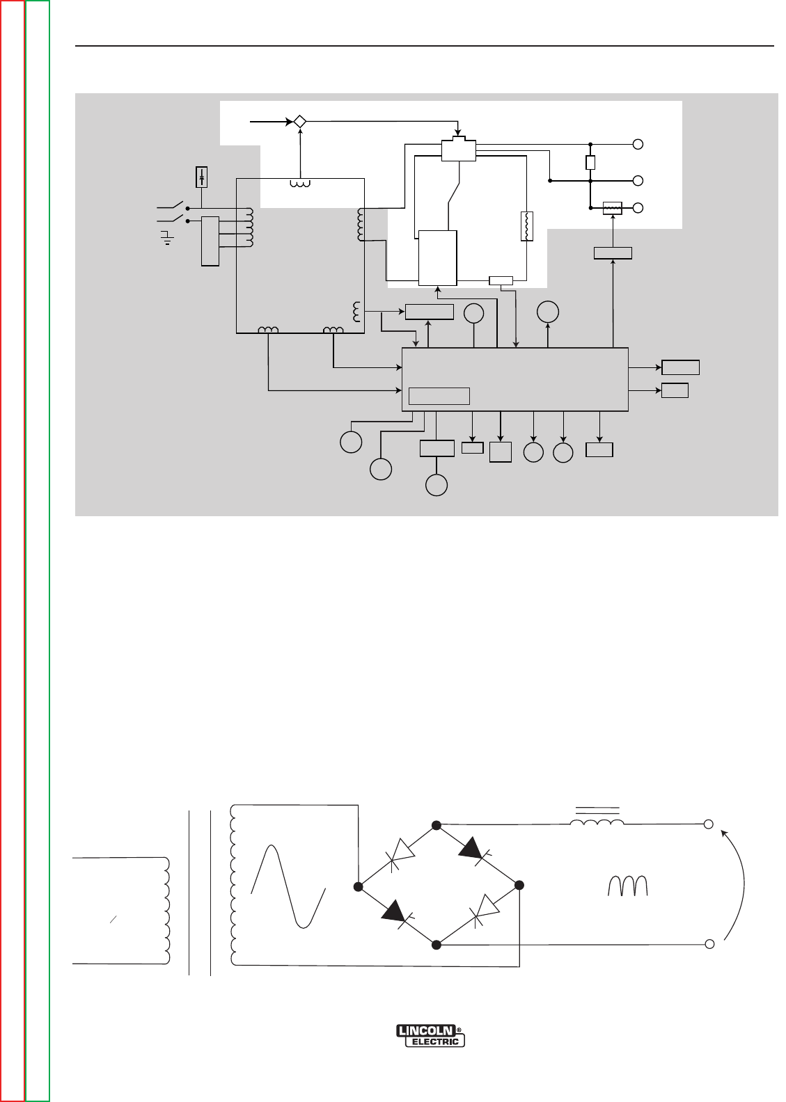
E-5E-5
PRECISION TIG 275
Return to Section TOC Return to Section TOC Return to Section TOC Return to Section TOC
Return to Master TOC Return to Master TOC Return to Master TOC Return to Master TOC
DC WELDING OUTPUT
When the polarity switch is placed in either DC position, the
AC voltage from the main transformer secondary is applied
to the SCR bridge. The SCR bridge and choke circuits are
connected in the conventional full wave bridge and filter
configuration, resulting in a controlled DC output. Since
the choke is in series with the negative leg of the bridge
and also in series with the welding load, a filtered DC is
applied to the output terminals. The bypass board pro-
tects the internal circuitry from interference.
When the machine is in the DC mode, the background cir-
cuitry provides an added boost of voltage to the output
terminals. This circuitry is controlled by the control board.
THEORY OF OPERATION
FIGURE E.5 – DC WELDING OUTPUT
POWER
SWITCH
RECONNECT
PANEL
OPTIONAL POWER
FACTOR
POLARITY
SWITCH
BYPASS BOARD
WORK
FRONT
ELECTRODE
REAR
ELECTRODE
78 VAC
X1
X2
AC
AC
DC
DC SHUNT
CHOKE
HIGH FREQUENCY
TRANSFORMER
HIGH VOLTAGE
TRANSFORMER
THERMOSTAT
115 VAC
115 VAC
115 VAC
FAN
GATE LEADS
FEEDBACK
GAS
SOLENOID
115 VAC
115 VAC
LED's
THERMOSTAT
20 VAC
20 VAC
CONTROL BOARD
BACKGROUND
CIRCUIT
FROM
CONTROL
BOARD
63.5 VAC
CORRECTION
CAPACITORS
REAR GANG
SCR
BRIDGE
ADVANCED CONTROL
PANEL RECEPTACLE
MINIMUM
OUTPUT
CONTROL
MAXIMUM
OUTPUT
CONTROL
PROTECTION
BOARD
REMOTE
RECEPTACLE
METER STICK
TIG
SWITCH
BALANCE
CONTROL
POST
FLOW
LOCAL/REMOTE
SWITCH
FIGURE E.6 DC WELDING CURRENT GENERATION
G
G
G
G
CHOKE
ELECTRODE
WORK
DC
PRIMARY
10

E-6E-6
PRECISION TIG 275
AC WELDING OUTPUT
Rotating the polarity switch to the AC position changes
the welding power circuit. One lead (X1) of the main
transformer secondary is connected to the machineʼs
output work terminal. The other secondary lead (X2) is
connected to one of the AC connections of the SCR
bridge. The electrode terminal is connected to the
other AC side of the bridge. The choke is now
electrically across the negative and positive SCR
bridge connections. With the ability of the choke to
store energy and the SCRs to turn on at the appropri-
ate times, an AC square wave is developed and
applied to the output terminals. The bypass board pro-
tects the internal circuitry from interference.
THEORY OF OPERATION
FIGURE E.7 – AC WELDING OUTPUT
POWER
SWITCH
RECONNECT
PANEL
OPTIONAL POWER
FACTOR
POLARITY
SWITCH
BYPASS BOARD
WORK
FRONT
ELECTRODE
REAR
ELECTRODE
78 VAC
X1
X2
AC
AC
DC
DC SHUNT
CHOKE
HIGH FREQUENCY
TRANSFORMER
HIGH VOLTAGE
TRANSFORMER
THERMOSTAT
115 VAC
115 VAC
115 VAC
FAN
GATE LEADS
FEEDBACK
GAS
SOLENOID
115 VAC
115 VAC
LED's
THERMOSTAT
20 VAC
20 VAC
CONTROL BOARD
BACKGROUND
CIRCUIT
FROM
CONTROL
BOARD
63.5 VAC
CORRECTION
CAPACITORS
REAR GANG
SCR
BRIDGE
ADVANCED CONTROL
PANEL RECEPTACLE
MINIMUM
OUTPUT
CONTROL
MAXIMUM
OUTPUT
CONTROL
PROTECTION
BOARD
REMOTE
RECEPTACLE
METER STICK
TIG
SWITCH
BALANCE
CONTROL
POST
FLOW
LOCAL/REMOTE
SWITCH
FIGURE E.8 DC WELDING CURRENT GENERATION
G
CHOKE
ELECTRODE
WORK
DC
PRIMARY
10
G
G
G
Return to Section TOC Return to Section TOC Return to Section TOC Return to Section TOC
Return to Master TOC Return to Master TOC Return to Master TOC Return to Master TOC
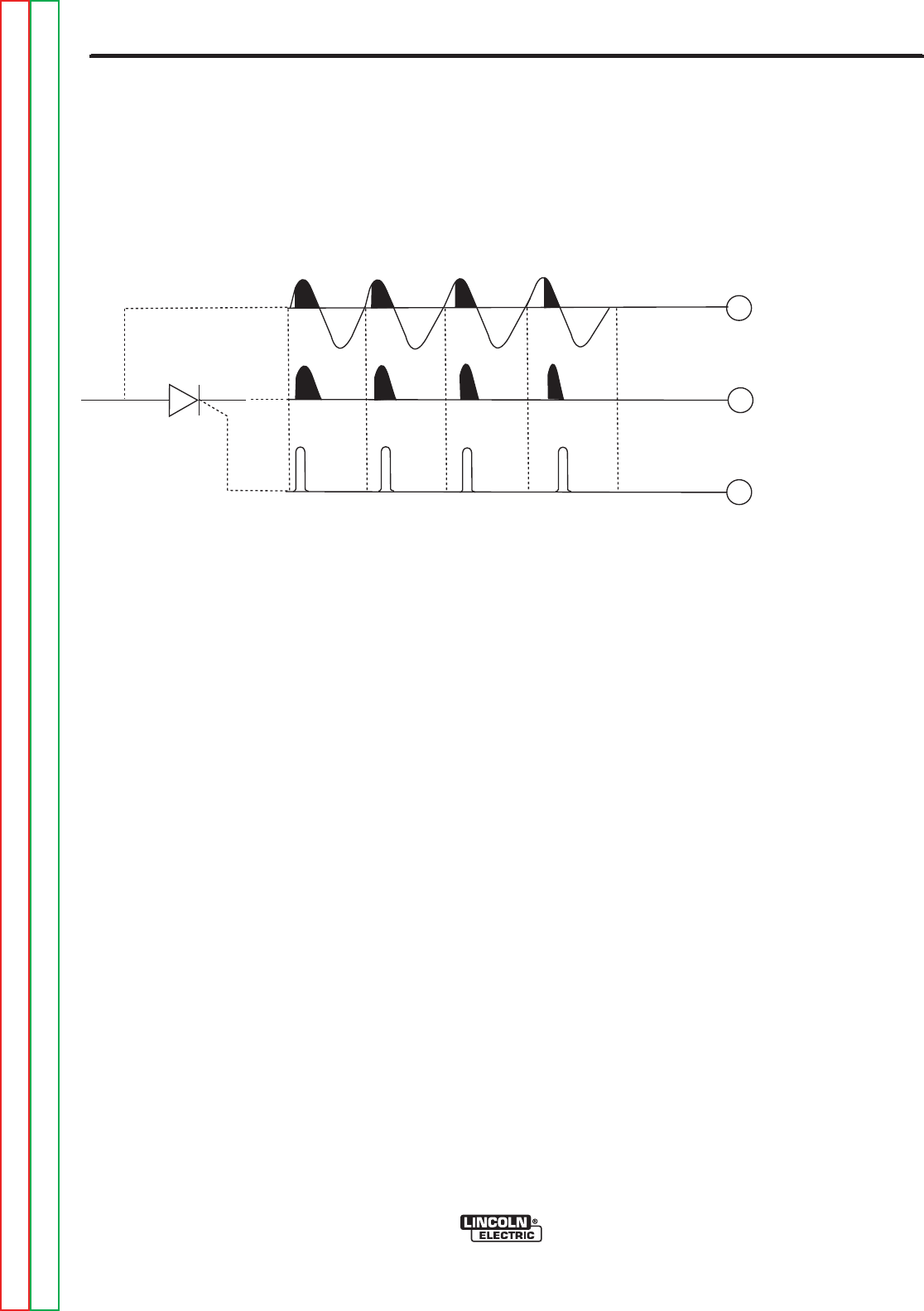
E-7E-7
PRECISION TIG 275
Return to Section TOC Return to Section TOC Return to Section TOC Return to Section TOC
Return to Master TOC Return to Master TOC Return to Master TOC Return to Master TOC
SCR OPERATION
A silicon controlled rectifier (SCR) is a three-terminal
device used to control rather large currents to a load.
An SCR acts very much like a switch. When a gate sig-
nal is applied to the SCR, it is turned ON and there is
current flow from anode to cathode. In the ON state
the SCR acts like a closed switch. When the SCR is
turned OFF there is no current flow from anode to cath-
ode. Thus, the device acts like an open switch. As the
name suggests, the SCR is a rectifier, so it passes cur-
rent only during positive half cycles of the AC supply.
The positive half cycle is the portion of the sine wave in
which the anode of the SCR is more positive than the
cathode.
When an AC supply voltage is applied to the SCR, the
device spends a certain portion of the AC cycle time in
the ON state and the remainder of the time in the OFF
state. The amount of time spent in the ON state is con-
trolled by the gate.
An SCR is fired by a short burst of current into the gate.
This gate pulse must be more positive than the cath-
ode voltage. Since there is a standard PN junction
between gate and cathode, the voltage between these
terminals must be slightly greater than 0.6V. Once the
SCR has fired, it is not necessary to continue the flow
of gate current. As long as current continues to flow
from anode to cathode, the SCR will remain on. When
the anode to cathode current drops below a minimum
value, called holding current, the SCR will shut off.
This normally occurs as the AC supply voltage passes
through zero into the negative portion of the sine wave.
If the SCR is turned on early in the positive half cycle
the conduction time is longer, resulting in greater SCR
output. If the gate firing occurs later in the cycle the
conduction time is less, resulting in lower SCR output.
THEORY OF OPERATION
FIGURE E.9 – SCR OPERATION
NOTE: AS THE GATE
PULSE IS APPLIED
LATER IN THE CYCLE
THE SCR OUTPUT
IS DECREASED.
ANODE
CATHODE
GATE
GATE
OUTPUT
INPUT

E-8E-8
PRECISION TIG 275
PROTECTION CIRCUITS
Protection circuits are designed into the PRECISION
Tig 275 machine to sense trouble and shut down the
machine before the trouble damages internal machine
components. Both thermal protection and current over-
load are included.
FAN-AS-NEEDED (F.A.N.)
The PRECISION Tig 275 has the F.A.N. circuit feature,
which means that the cooling fan will operate only
while welding; then for about eight minutes after weld-
ing has stopped to assure proper machine cooling.
This helps reduce the amount of dirt and dust drawn
into the machine along with the cooling air. The cooling
fan will operate briefly when the machine power is ini-
tially turned on, and continuously while the yellow
Thermal shutdown light is lit.
THERMAL PROTECTION
This welder has thermostatic protection from excessive
duty cycles, overloads, loss of cooling and excessive
ambient temperatures. When the welder is subjected
to an overload, or inadequate cooling, the primary coil
thermostat and/or secondary coil thermostat will open.
This condition will be indicated by the illumination of
the yellow Thermal Shutdown light on the front panel.
The fan will continue to run to cool the power source.
Postflow occurs when Tig welding is shut down, but no
welding is possible until the machine is allowed to cool
and the yellow Thermal Shutdown light goes out. Once
the machine cools sufficiently, the thermostats are self-
resetting. If the shutdown is caused by excessive out-
put or duty cycle and the fan is operating normally, the
power may be left on and the reset should occur with-
in a 15 minute period. If the fan is not functioning prop-
erly or the air intake louvers are obstructed, the input
power must be removed and the fan problem or air
obstruction corrected.
OVERLOAD PROTECTION
The machine is electronically protected from producing
excessively high output currents. The output is limited
to 350 amps.
THEORY OF OPERATION
Return to Section TOC Return to Section TOC Return to Section TOC Return to Section TOC
Return to Master TOC Return to Master TOC Return to Master TOC Return to Master TOC

F-1F-1
PRECISION TIG 275
Return to Master TOC Return to Master TOC Return to Master TOC Return to Master TOC
Troubleshooting & Repair Section ................................................................................Section F
How to Use Troubleshooting Guide .......................................................................................F-2
PC Board Troubleshooting Procedures and Replacement....................................................F-3
Troubleshooting Guide...........................................................................................................F-4
Test Procedures
Meter Calibration Adjustments ......................................................................................F-19
High Frequency Circuit Disable Procedure ...................................................................F-23
Protection Board Test ....................................................................................................F-25
T1 Main Transformer Test .............................................................................................F-27
Gas (Water) Solenoid Test ............................................................................................F-31
Static SCR Test .............................................................................................................F-33
Active SCR Test.............................................................................................................F-35
Typical Output Voltage Waveform (DC Tig Mode) ........................................................F-39
Typical Output Voltage Waveform (AC Tig Mode).........................................................F-40
Typical AC Voltage Waveform - 50 AMPS (AC Tig Mode) ............................................F-41
Typical AC Voltage Waveform - 2 AMPS (AC Tig Mode) ..............................................F-42
Typical Output Voltage Waveform - 200 AMPS ( DC Tig Mode)..................................F-43
Replacement Procedures
High Voltage Transformer Removal & Replacement.....................................................F-45
Control Board Removal and Replacement....................................................................F-49
SCR Bridge Assembly Removal and Replacement ......................................................F-53
Polarity Switch Removal and Replacement ..................................................................F-57
SCR Removal and Replacement ..................................................................................F-59
Retest after Repair ........................................................................................................F-61
TABLE OF CONTENTS
TROUBLESHOOTING & REPAIR SECTION

F-2F-2
PRECISION TIG 275
HOW TO USE TROUBLESHOOTING GUIDE
Service and repair should be performed by only Lincoln Electric Factory Trained Personnel.
Unauthorized repairs performed on this equipment may result in danger to the technician and machine
operator and will invalidate your factory warranty. For your safety and to avoid Electrical Shock, please
observe all safety notes and precautions detailed throughout this manual.
TROUBLESHOOTING & REPAIR
CAUTION
This Troubleshooting Guide is provided to help
you locate and repair possible machine malfunc-
tions. Simply follow the three-step procedure list-
ed below.
Step 1. LOCATE PROBLEM (SYMPTOM). Look
under the column labeled “PROBLEM” (SYMP-
TOMS). This column describes possible symp-
toms that the machine may exhibit. Find the list-
ing that best describes the symptom that the
machine is exhibiting. Symptoms are grouped
into four main categories: Output Problems,
Function Problems, Cutting Problems and LED
Function Problems.
Step 2. PERFORM EXTERNAL TESTS.
The second column, labeled “POSSIBLE AREAS
OF MISADJUSTMENT(S)”, lists the obvious
external possibilities that may contribute to the
machine symptom. Perform these tests/checks in
the order listed. In general, these tests can be
conducted without removing the case wrap-
around cover.
Step 3. RECOMMENDED COURSE OF
ACTION The
last column, labeled “Recommended Course of
Action” lists the most likely components that may
have failed in your machine. It also specifies the
appropriate test procedure to verify that the sub-
ject component is either good or bad. If there are
a number of possible components, check the
components in the order listed to eliminate one
possibility at a time until you locate the cause of
your problem.
All of the referenced test procedures referred to in
the Troubleshooting Guide are described in detail
at the end of this chapter. Refer to the
Troubleshooting and Repair Table of Contents to
locate each specific Test Procedure. All of the
referred to test points, components, terminal
strips, etc., can be found on the referenced elec-
trical Wiring Diagrams and Schematics. Refer to
the Electrical Diagrams Section Table of Contents
to locate the appropriate diagram.
If for any reason you do not understand the test procedures or are unable to perform the test/repairs
safely, contact the Lincoln Electric Service Department for electrical troubleshooting assistance before
you proceed. Call 1-888-935-3877.
HIGH VOLTAGE/ HIGH FREQUENCY can damage test equipment.
* Perform all voltage and wave form checks with high frequency circuit OFF.
Perform High Frequency Disable Procedure.
Return to Section TOC Return to Section TOC Return to Section TOC Return to Section TOC
Return to Master TOC Return to Master TOC Return to Master TOC Return to Master TOC
WARNING
CAUTION
WARNING
ELECTRIC SHOCK can kill.
*Have an electrician install and service
this equipment. Turn the machine
OFF before working on equipment.
Do not touch electrically hot parts.
Sometimes machine failures appear to be due to PC
Board failures. These problems can sometimes be
traced to poor electrical connections. To avoid prob-
lems when troubleshooting and replacing PC Boards,
please use the following procedure:
1. Determine to the best of your technical ability that
the PC Board is the most likely component causing
the failure symptom.
2. Check for loose connections at the PC Board to
assure that the PC Board is properly connected.
3. If the problem persists, replace the suspect PC
Board using standard practices to avoid static elec-
trical damage and electrical shock. Read the warn-
ing inside the static resistant bag and perform the
following procedures:
PC Board can be damaged by
static electricity.
• Remove your bodyʼs static charge
before opening the static-shielding
bag. Wear an anti-static wrist
strap. For safety, use a 1 Meg ohm
resistive cord con nected to a
grounded part of the equipment
frame.
• If you donʼt have a wrist strap,
touch an unpainted, grounded,
part of the equipment frame. Keep
touching the frame to prevent stat-
ic build-up. Be sure not to touch
any electrically live parts at the
same time.
• Tools which come in contact with the PC Board must
be either conductive, anti-static or static-disipative.
• Remove the PC Board from the static-shielding bag
and place it directly into the equipment. Donʼt set the
PC Board on or near paper, plastic or cloth which
could have a static charge. If the PC Board canʼt be
installed immediately, put it back in the static-shielding
bag.
• If the PC Board uses protective shorting jumpers,
donʼt remove them until installation is complete.
• If you return a PC Board to The Lincoln Electric
Company for credit, it must be in the static-shielding
bag. This will prevent further damage and allow prop-
er failure analysis.
4. Test the machine to determine if the failure symp-
tom has been corrected by the replacement PC
Board.
.......................................................................................
NNOOTTEE::It is desirable to have a spare (known good) PC
Board available for PC Board troubleshooting.
NNOOTTEE::Allow the machine to heat up so that all electri-
cal components can reach their operating tem-
perature.
5. Remove the replacement PC Board and substitute
it with the original PC Board to recreate the original
problem.
a. If the original problem does not reappear
by substituting the original board, then the
PC Board was not the problem. Continue
to look for bad connections in the control
wiring harness, junction blocks, and termi-
nal strips.
b. If the original problem is recreated by the
substitution of the original board, then the
PC Board was the problem. Reinstall the
replacement PC Board and test the
machine.
6. Always indicate that this procedure was followed
when warranty reports are to be submitted.
NNOOTTEE:Following this procedure and writing on the
warranty report, “INSTALLED AND
SWITCHED PC BOARDS TO VERIFY PROB-
LEM,” will help avoid denial of legitimate PC
Board warranty claims.
F-3 F-3
PRECISION TIG 275
Return to Section TOC Return to Section TOC Return to Section TOC Return to Section TOC
Return to Master TOC Return to Master TOC Return to Master TOC Return to Master TOC
TROUBLESHOOTING & REPAIR
PC BOARD TROUBLESHOOTING PROCEDURES
ATTENTION
Static-Sensitive
Devices
Handle only at
Static-Safe
Workstations
WARNING

F-4F-4
PRECISION TIG 275
TROUBLESHOOTING & REPAIR
Observe Safety Guidelines TROUBLESHOOTING GUIDE
detailed in the beginning of this manual.
If for any reason you do not understand the test procedures or are unable to perform the test/repairs safely, con-
tact the Lincoln Electric Service Department for electrical troubleshooting assistance before you proceed.
Call 1-888-935-3877.
PROBLEMS
(SYMPTOMS)
POSSIBLE AREAS OF
MISADJUSTMENT(S)
RECOMMENDED
COURSE OF ACTION
OUTPUT PROBLEMS
The machine is dead. No weld out-
put – no 115 VAC at the receptacle.
1. Check the input voltage. The
input voltage must match the rat-
ing plate and the voltage con-
nection. Refer to Reconnect
Procedure in the Installation
section of this manual.
2. Make sure that the input power
switch is in the “ON” position.
3. Check for blown or missing
fuses in the input lines.
4. Check circuit breaker CB1.
Reset if necessary.
1. Check the input power switch,
reconnect panel and associated
wires for loose or faulty connec-
tions.
2. The input power switch may be
faulty.
3. Perform the T1 Transformer
Test.
Return to Section TOC Return to Section TOC Return to Section TOC Return to Section TOC
Return to Master TOC Return to Master TOC Return to Master TOC Return to Master TOC
CAUTION

F-5F-5
PRECISION TIG 275
Return to Section TOC Return to Section TOC Return to Section TOC Return to Section TOC
Return to Master TOC Return to Master TOC Return to Master TOC Return to Master TOC
TROUBLESHOOTING & REPAIR
TROUBLESHOOTING GUIDE Observe Safety Guidelines
detailed in the beginning of this manual.
If for any reason you do not understand the test procedures or are unable to perform the test/repairs safely, con-
tact the Lincoln Electric Service Department for electrical troubleshooting assistance before you proceed.
Call 1-888-935-3877.
PROBLEMS
(SYMPTOMS)
POSSIBLE AREAS OF
MISADJUSTMENT(S)
RECOMMENDED
COURSE OF ACTION
OUTPUT PROBLEMS
No welding output. The 115 VAC is
present at the receptacle.
NOTE: BEFORE REPLACING A
CONTROL BOARD
If an Advanced Control Panel is
installed, remove it and replace
the Jumper in connector J-3. If
the machine functions normally,
the Advanced Process panel or
harness is defective.
1. Make sure the polarity switch is
in the proper position and func-
tioning correctly.
2. One of the thermostats may be
tripped. Allow the machine to
cool. The thermal light will be
on.
3. Make sure the welding cables,
torch and connections are in
good operating condition.
1. Check for loose or faulty connec-
tions on the heavy current carry-
ing leads. ( Polarity switch, out-
put choke, output terminals, etc.)
2. Check for faulty connections or a
defective thermostat. Check
leads #213 and #214. See the
Wiring Diagram. The thermal
light will be on.
3. Perform the T1 Transformer
Test.
4. Perform the SCR Bridge Test.
5. Check the output controls R1, R4
and associated wiring. See
Wiring Diagram.
6. Check the J4 connection on the
control board.
7. The control board may be faulty.
CAUTION

F-6F-6
PRECISION TIG 275
TROUBLESHOOTING & REPAIR
Observe Safety Guidelines TROUBLESHOOTING GUIDE
detailed in the beginning of this manual.
If for any reason you do not understand the test procedures or are unable to perform the test/repairs safely, con-
tact the Lincoln Electric Service Department for electrical troubleshooting assistance before you proceed.
Call 1-888-935-3877.
PROBLEMS
(SYMPTOMS)
POSSIBLE AREAS OF
MISADJUSTMENT(S)
RECOMMENDED
COURSE OF ACTION
OUTPUT PROBLEMS
No output from the machine in
either Stick or TIG modes. The
thermal light is on.
NOTE: BEFORE REPLACING A
CONTROL BOARD
If an Advanced Control Panel is
installed, remove it and replace
the Jumper in connector J-3. If
the machine functions normally,
the Advanced Process panel or
harness is defective.
1. The welding application may
have exceeded the recommend-
ed duty cycle. Allow the fan to
cool the until the thermal light is
off.
2. The air louvers may be blocked.
Remove the air obstruction and
allow the unit to cool.
1. One of the thermostats may be
faulty. Check or replace. See
the Wiring Diagram.
2. Check for loose or faulty wires
on the thermostats and associat-
ed circuitry. See the Wiring
Diagram.
3. The fan motor may be faulty or
mechanically obstructed. The
fan should run when welding or
when a thermostat is open.
4. The control board may be faulty.
The machine does not respond (no
gas flow, no high frequency and no
open circuit voltage) when the arc
start switch or Amptrol is activated.
The thermal light is not lit.
NOTE: BEFORE REPLACING A
CONTROL BOARD
If an Advanced Control Panel is
installed, remove it and replace
the Jumper in connector J-3. If
the machine functions normally,
the Advanced Process panel or
harness is defective.
1. Make sure the machine is in the
TIG mode.
2. The Amptrol or arc start switch
may be defective. Check for
continuity ( zero ohms) between
pins “D” and “E” on the cable
connector when the Amptrol or
arc start is pressed.
3. Check the Local/Remote switch
for proper operation.
1. Perform the Protection Board
Test.
2. Perform the T1 Transformer
Test.
3. The control board may be faulty.
Return to Section TOC Return to Section TOC Return to Section TOC Return to Section TOC
Return to Master TOC Return to Master TOC Return to Master TOC Return to Master TOC
CAUTION

The machine has welding output in
the Stick mode but no output in the
TIG mode. ( no gas flow or high fre-
quency).
SEE NOTE BELOW
1. Make sure the Stick/TIG switch
is in the proper position and
operating correctly.
2. The remote control device may
be faulty.
1. Check the remote control recep-
tacle and associated wiring. See
the Wiring Diagram.
2. Perform the Protection Board
Test.
3. Check the J11 plug on the con-
trol board. See the Wiring
Diagram.
4. The control board may be faulty.
The machine welds at a very low
output regardless of the current
control setting.
NOTE: BEFORE REPLACING A
CONTROL BOARD
If an Advanced Control Panel is
installed, remove it and replace
the Jumper in connector J-3. If
the machine functions normally,
the Advanced Process panel or
harness is defective.
1. If welding in the TIG mode, the
remote control device may be
defective.
2. Make certain the input line volt-
age is correct for the machineʼs
reconnect configuration.
3. Check the welding cables and/
or torch for loose or faulty con-
nections.
1. Check the polarity switch and
associated leads.
2. Check the interior connections of
the heavy current carrying leads.
3. Perform the SCR Bridge Test.
4. Perform the T1 Transformer
Test.
5. Check the output current con-
trols for proper operation.
Normal resistance is 10,000
ohms. See the Wiring Diagram.
6. The control board may be faulty.
F-7F-7
PRECISION TIG 275
Return to Section TOC Return to Section TOC Return to Section TOC Return to Section TOC
Return to Master TOC Return to Master TOC Return to Master TOC Return to Master TOC
TROUBLESHOOTING & REPAIR
TROUBLESHOOTING GUIDE Observe Safety Guidelines
detailed in the beginning of this manual.
If for any reason you do not understand the test procedures or are unable to perform the test/repairs safely, con-
tact the Lincoln Electric Service Department for electrical troubleshooting assistance before you proceed.
Call 1-888-935-3877.
PROBLEMS
(SYMPTOMS)
POSSIBLE AREAS OF
MISADJUSTMENT(S)
RECOMMENDED
COURSE OF ACTION
OUTPUT PROBLEMS
The machine does not have welding
output in the Stick mode. The
machine operates correctly in the
TIG mode.
SEE NOTE BELOW
1. Check the electrode cable and
holder for loose or faulty connec-
tions.
2. Make sure the Stick/TIG switch is
in the proper position and operat-
ing correctly.
1. Check the Stick/TIG switch and
associated leads. See the Wiring
Diagram.
2. The control board may be faulty.
CAUTION

F-8F-8
PRECISION TIG 275
TROUBLESHOOTING & REPAIR
Observe Safety Guidelines TROUBLESHOOTING GUIDE
detailed in the beginning of this manual.
If for any reason you do not understand the test procedures or are unable to perform the test/repairs safely, con-
tact the Lincoln Electric Service Department for electrical troubleshooting assistance before you proceed.
Call 1-888-935-3877.
PROBLEMS
(SYMPTOMS)
POSSIBLE AREAS OF
MISADJUSTMENT(S)
RECOMMENDED
COURSE OF ACTION
OUTPUT PROBLEMS
The machine welds at a very high
output regardless of the current
control setting.
NOTE: BEFORE REPLACING A
CONTROL BOARD
If an Advanced Control Panel is
installed, remove it and replace
the Jumper in connector J-3. If
the machine functions normally,
the Advanced Process panel or
harness is defective.
1. If welding in the TIG mode, the
remote control device may be
defective.
1. Perform the SCR Bridge Test.
2. Perform the T1 Transformer
Test.
3. Check the output current con-
trols for proper operation.
Normal resistance is 10,000
ohms. See the Wiring Diagram.
4. Check leads #221 and #222
between the output shunt and
the control board. See the
Wiring Diagram.
5. The control board may be faulty
Accessories plugged into the volt
receptacle do not work.
1. Make sure the accessory plug
and associated leads are in good
working condition.
2. Make certain the correct input
voltage is being applied to the
machine. (The reconnect lead
must be in the correct position.)
3. The circuit breaker CB1 may be
tripped. Reset if necessary.
4. Only the top part of the recepta-
cle is electronically “Hot” all of
the time.
1. The circuit breaker (CB1) may be
faulty.
2. Check the receptacle and asso-
ciated leads for loose or faulty
connections.
3. Perform the T1 Transformer
Test.
Return to Section TOC Return to Section TOC Return to Section TOC Return to Section TOC
Return to Master TOC Return to Master TOC Return to Master TOC Return to Master TOC
CAUTION

F-9F-9
PRECISION TIG 275
Return to Section TOC Return to Section TOC Return to Section TOC Return to Section TOC
Return to Master TOC Return to Master TOC Return to Master TOC Return to Master TOC
TROUBLESHOOTING & REPAIR
TROUBLESHOOTING GUIDE Observe Safety Guidelines
detailed in the beginning of this manual.
If for any reason you do not understand the test procedures or are unable to perform the test/repairs safely, con-
tact the Lincoln Electric Service Department for electrical troubleshooting assistance before you proceed.
Call 1-888-935-3877.
PROBLEMS
(SYMPTOMS)
POSSIBLE AREAS OF
MISADJUSTMENT(S)
RECOMMENDED
COURSE OF ACTION
OUTPUT PROBLEMS
The machine makes a very loud
buzzing noise in DC Stick or in DC
TIG modes. There is no current
draw from the machineʼs output ter-
minals. (The machine is not exter-
nally loaded).
1. Inspect the output terminal insu-
lators for cracks or signs of over-
heating.
1. Diode D1 may be shorted.
Check and replace if necessary.
2. Check the polarity switch (S2) for
proper function and correct con-
nections.
3. Perform the SCR Bridge Tests.
CAUTION

F-10F-10
PRECISION TIG 275
TROUBLESHOOTING & REPAIR
Observe Safety Guidelines TROUBLESHOOTING GUIDE
detailed in the beginning of this manual.
If for any reason you do not understand the test procedures or are unable to perform the test/repairs safely, con-
tact the Lincoln Electric Service Department for electrical troubleshooting assistance before you proceed.
Call 1-888-935-3877.
PROBLEMS
(SYMPTOMS)
POSSIBLE AREAS OF
MISADJUSTMENT(S)
RECOMMENDED
COURSE OF ACTION
TIG WELDING PROBLEMS
The machine output is intermittent-
ly lost. Gas flow and high frequen-
cy are also interrupted.
NOTE: BEFORE REPLACING A
CONTROL BOARD
If an Advanced Control Panel is
installed, remove it and replace
the Jumper in connector J-3. If
the machine functions normally,
the Advanced Process panel or
harness is defective.
1. The problem may be caused by
high frequency interference.
Make sure that the machine is
grounded properly according to
the installation instructions. If
there are other high frequency
sources in the area, make cer-
tain that they are grounded prop-
erly.
2. Make sure the Amptrol is operat-
ing properly.
3. Check to make sure that the
input voltage is correct for the
machine. Refer to Reconnect
Procedure in the Installation
section of this manual.
1. Check for loose or faulty con-
nections on the leads between
the remote receptacle, the pro-
tection board and plug J22 on
the protection board. See the
Wiring Diagram.
2. Check plugs J5 and J23 on the
protection board for loose or
faulty connections.
3. Perform the Protection Board
Test.
4. The control board may be faulty.
5. Check the ground connection of
the bypass/ stabilizer P.C.
Board. See the Wiring Diagram.
No gas or water flow (with option-
al water solenoid) when the arc
start switch or Amptrol is activated
in the TIG mode. All other ma -
chine functions are normal.
1. The gas (or water) supply is
either empty or not turned on.
2. The low regulator may be set too
low.
3. Check the supply hoses for
kinks or blockages.
4. The filters may be blocked.
1. Perform the Gas Solenoid Test.
2. The control board may be faulty.
Return to Section TOC Return to Section TOC Return to Section TOC Return to Section TOC
Return to Master TOC Return to Master TOC Return to Master TOC Return to Master TOC
CAUTION
F-11F-11
PRECISION TIG 275
Return to Section TOC Return to Section TOC Return to Section TOC Return to Section TOC
Return to Master TOC Return to Master TOC Return to Master TOC Return to Master TOC
TROUBLESHOOTING & REPAIR
TROUBLESHOOTING GUIDE Observe Safety Guidelines
detailed in the beginning of this manual.
If for any reason you do not understand the test procedures or are unable to perform the test/repairs safely, con-
tact the Lincoln Electric Service Department for electrical troubleshooting assistance before you proceed.
Call 1-888-935-3877.
PROBLEMS
(SYMPTOMS)
POSSIBLE AREAS OF
MISADJUSTMENT(S)
RECOMMENDED
COURSE OF ACTION
TIG WELDING PROBLEMS
No high frequency. The machine is
in the TIG mode and has normal
output.
NOTE: BEFORE REPLACING A
CONTROL BOARD
If an Advanced Control Panel is
installed, remove it and replace
the Jumper in connector J-3. If
the machine functions normally,
the Advanced Process panel or
harness is defective.
1. If the machine is in a dirty envi-
ronment with conductive contam-
inants, check and clean the
spark gap with a low pressure air
stream per the maintenance
instructions.
2. Check the spark gap operations
and setting. Normal is (0.015”).
Refer to the Maintenance
Section of this manual.
3. Check circuit breaker CB1.
Reset if necessary.
4. Check connection J12 on the
control board.
1. Check the high voltage trans-
former (T2). The normal resis-
tance of the secondary winding is
12.5k ohms.
ELECTRIC SHOCK
CAN KILL. When
115 VAC is applied
to T2, a very high
voltage is devel-
oped on the secondary winding. For
assistance, call the Lincoln Electric
Service Department. 1-888-935-
3877.
2. Check R5, C6, C7, L2 and L3.
Replace if defective.
3. The control board may be faulty.
The High frequency is on continu-
ously in DC TIG or shuts off in AC
TIG.
1. None 1. Check plug J11 on the control
board. See the Wiring Diagram.
2. Check micro-switch S2A for
proper operation. See the Wiring
Diagram.
3. The control board may be faulty.
WARNING
CAUTION

F-12F-12
PRECISION TIG 275
TROUBLESHOOTING & REPAIR
Observe Safety Guidelines TROUBLESHOOTING GUIDE
detailed in the beginning of this manual.
If for any reason you do not understand the test procedures or are unable to perform the test/repairs safely, con-
tact the Lincoln Electric Service Department for electrical troubleshooting assistance before you proceed.
Call 1-888-935-3877.
PROBLEMS
(SYMPTOMS)
POSSIBLE AREAS OF
MISADJUSTMENT(S)
RECOMMENDED
COURSE OF ACTION
TIG WELDING PROBLEMS
High frequency “spark” is present
but weak.
1. The spark gap may be too large.
Check and reset per instructions
in the Maintenance Section of
this manual.
2. The work and/or torch cables
may be in poor condition allow-
ing the high frequency to “leak”
to ground. Use good quality
cables, preferably those with a
high natural rubber content and
as short as possible.
3. If helium shielding gas is being
used, reduce the percentage of
helium.
4. Make sure the tungsten elec-
trode is the correct size for the
process.
1. The high voltage transformer
(T2) may be faulty.
2. Capacitor C6 may be faulty.
3. The high frequency transformer
(T3) may be faulty.
Poor arc starting in the DC TIG
mode.
1. The input line voltage may be
low.
2. Check the torch and work cable
for loose or faulty connections.
1. Check the J11 plug on the con-
trol board. See Wiring Diagram.
2. Check the background resistor
R7. Normal resistance is 20
ohms.
3. Check the background diode
bridge.
Return to Section TOC Return to Section TOC Return to Section TOC Return to Section TOC
Return to Master TOC Return to Master TOC Return to Master TOC Return to Master TOC
CAUTION

F-13F-13
PRECISION TIG 275
Return to Section TOC Return to Section TOC Return to Section TOC Return to Section TOC
Return to Master TOC Return to Master TOC Return to Master TOC Return to Master TOC
TROUBLESHOOTING & REPAIR
TROUBLESHOOTING GUIDE Observe Safety Guidelines
detailed in the beginning of this manual.
If for any reason you do not understand the test procedures or are unable to perform the test/repairs safely, con-
tact the Lincoln Electric Service Department for electrical troubleshooting assistance before you proceed.
Call 1-888-935-3877.
PROBLEMS
(SYMPTOMS)
POSSIBLE AREAS OF
MISADJUSTMENT(S)
RECOMMENDED
COURSE OF ACTION
TIG WELDING PROBLEMS
The high frequency “spark” is pre-
sent at the tungsten electrode, but
the operator is unable to establish
a welding arc. The machine has a
normal open circuit voltage. Refer
to Technical Specifications in the
Installation section.
1. The torch may be faulty. Check
or replace.
2. The current control may be set
too low.
3. The tungsten electrode may be
contaminated. Replace or
sharpen.
4. The electrode may be too large
for the process.
5. If a helium blend is being used
as a shielding gas, reduce the
percentage of helium.
6. Check the welding cables for
loose or faulty connections.
1. Check spark gap adjustment.
See the Maintenance Section.
2. This may be a welding proce-
dure problem. Contact the
Lincoln Service Department,
Technical Sales group at 1-888-
935-3877.
When AC TIG welding, the arc is
erratic and there is a loss of “clean-
ing” of the work piece.
1. The tungsten electrode may be
small for the process. Use a larg-
er diameter tungsten or a pure
tungsten.
2. If a helium blend is used as a
shielding gas, reduce the per-
centage of helium.
3. Check the balance control set-
ting.
1. Check components R5 and C7 in
the high voltage transformer pri-
mary circuit.
2. Perform the SCR Bridge Test.
Arc “pulsates” in AC polarity. DC
TIG is OK.
1. Check that the machine controls
are set correctly for the process.
1. Micro switch S2A may be faulty.
It should “open” in the AC mode.
See the Wiring Diagram.
CAUTION

F-14F-14
PRECISION TIG 275
TROUBLESHOOTING & REPAIR
Observe Safety Guidelines TROUBLESHOOTING GUIDE
detailed in the beginning of this manual.
If for any reason you do not understand the test procedures or are unable to perform the test/repairs safely, con-
tact the Lincoln Electric Service Department for electrical troubleshooting assistance before you proceed.
Call 1-888-935-3877.
PROBLEMS
(SYMPTOMS)
POSSIBLE AREAS OF
MISADJUSTMENT(S)
RECOMMENDED
COURSE OF ACTION
STICK WELDING PROBLEMS
The stick electrode “blasts-off”
when touched to the work piece.
NOTE: BEFORE REPLACING A
CONTROL BOARD
If an Advanced Control Panel is
installed, remove it and replace
the Jumper in connector J-3. If
the machine functions normally,
the Advanced Process panel or
harness is defective.
1. Welding current may be too high
for the electrode size. Reduce
current control setting or use a
larger diameter electrode.
1. Perform the SCR Bridge Test.
2. The control board may be faulty.
Variable or sluggish welding arc
when welding in the Stick mode.
1. Check the work and electrode
cables for loose or poor connec-
tions.
2. The welding cables may be too
small or too long to permit the
desired current to flow.
3. The welding current may be set
too low.
1. Check the polarity switch for
excessive wear or faulty connec-
tions.
2. Check the interior heavy current
carrying leads and connections.
Return to Section TOC Return to Section TOC Return to Section TOC Return to Section TOC
Return to Master TOC Return to Master TOC Return to Master TOC Return to Master TOC
CAUTION

F-15F-15
PRECISION TIG 275
Return to Section TOC Return to Section TOC Return to Section TOC Return to Section TOC
Return to Master TOC Return to Master TOC Return to Master TOC Return to Master TOC
TROUBLESHOOTING & REPAIR
TROUBLESHOOTING GUIDE Observe Safety Guidelines
detailed in the beginning of this manual.
If for any reason you do not understand the test procedures or are unable to perform the test/repairs safely, con-
tact the Lincoln Electric Service Department for electrical troubleshooting assistance before you proceed.
Call 1-888-935-3877.
PROBLEMS
(SYMPTOMS)
POSSIBLE AREAS OF
MISADJUSTMENT(S)
RECOMMENDED
COURSE OF ACTION
FUNCTION PROBLEMS
The meter does not display V (volt)
or minimum current.
NOTE: BEFORE REPLACING A
CONTROL BOARD
If an Advanced Control Panel is
installed, remove it and replace
the Jumper in connector J-3. If
the machine functions normally,
the Advanced Process panel or
harness is defective.
1. Check that either the advanced
control board or jumper plug is in
J3 on the control board.
1. Check R1 potentiometer and
associated leads between the
control board and plug J9. See
the Wiring Diagram.
2. The control board may be faulty.
CAUTION

F-16F-16
PRECISION TIG 275
If for any reason you do not understand the test procedures or are unable to perform the test/repairs safely, con-
tact the Lincoln Electric Service Department for electrical troubleshooting assistance before you proceed.
Call 1-888-935-3877.
PROBLEMS
(SYMPTOMS)
POSSIBLE AREAS OF
MISADJUSTMENT(S)
RECOMMENDED
COURSE OF ACTION
FUNCTION PROBLEMS
The AC wave balance control does
not function properly.
NOTE: BEFORE REPLACING A
CONTROL BOARD
If an Advanced Control Panel is
installed, remove it and replace
the Jumper in connector J-3. If
the machine functions normally,
the Advanced Process panel or
harness is defective.
1. The AC wave balance control is
operational only in the TIG mode.
1. Check the AC balance control
(R2) and associated leads for
loose or faulty connections. See
the Wiring Diagram.
2. The control board may be faulty.
Gas pre-flow and post-flow time is
too long.
1. If an advanced control board is
installed, check dip switch set-
ting on the board. See
Installation Manual.
1. Check plug J3 on the control
board. Either the jumper plug or
the advanced control board must
be plugged into J3.
TROUBLESHOOTING & REPAIR
TROUBLESHOOTING GUIDE Observe Safety Guidelines
detailed in the beginning of this manual.
Return to Section TOC Return to Section TOC Return to Section TOC Return to Section TOC
Return to Master TOC Return to Master TOC Return to Master TOC Return to Master TOC
CAUTION

F-17F-17
PRECISION TIG 275
Return to Section TOC Return to Section TOC Return to Section TOC Return to Section TOC
Return to Master TOC Return to Master TOC Return to Master TOC Return to Master TOC
TROUBLESHOOTING & REPAIR
Observe Safety Guidelines TROUBLESHOOTING GUIDE
detailed in the beginning of this manual.
If for any reason you do not understand the test procedures or are unable to perform the test/repairs safely, con-
tact the Lincoln Electric Service Department for electrical troubleshooting assistance before you proceed.
Call 1-888-935-3877.
PROBLEMS
(SYMPTOMS)
POSSIBLE AREAS OF
MISADJUSTMENT(S)
RECOMMENDED
COURSE OF ACTION
FUNCTION PROBLEMS
The meter does not display V (volt)
or minimum current.
NOTE: BEFORE REPLACING A
CONTROL BOARD
If an Advanced Control Panel is
installed, remove it and replace
the Jumper in connector J-3. If
the machine functions normally,
the Advanced Process panel or
harness is defective.
1. Toggle the display switch. It may
be dirty.
1. Check the leads between the
display switch and the control
board. See the Wiring Diagram.
2. The display switch may be faulty.
3. The control board may be faulty.
The meter does not light up. Other
machine functions are OK.
NOTE: BEFORE REPLACING A
CONTROL BOARD
If an Advanced Control Panel is
installed, remove it and replace
the Jumper in connector J-3. If
the machine functions normally,
the Advanced Process panel or
harness is defective.
1. None 1. Check the leads and connec-
tions between the meter and the
control board. See the Wiring
Diagram.
2. The meter may be faulty.
3. The control board may be faulty.
CAUTION


F-19F-19
PRECISION TIG 275
TROUBLESHOOTING & REPAIR
METER CALIBRATION ADJUSTMENTS
Service and repair should be performed by only Lincoln Electric factory trained personnel.
Unauthorized repairs performed on this equipment may result in danger to the technician
or machine operator and will invalidate your factory warranty. For your safety and to avoid
electrical shock, please observe all safety notes and precautions detailed throughout this
manual.
If for any reason you do not understand the test procedures or are unable to perform the
test/repairs safely, contact the Lincoln Electric Service Department for electrical trou-
bleshooting assistance before you proceed. Call 1-888-935-3877.
DESCRIPTION
This test will help aid the technician in meter circuits calibration.
MATERIALS NEEDED
Voltmeter/Ohmmeter
3/8” Nut Driver
Wiring Diagram
Return to Section TOC Return to Section TOC Return to Section TOC Return to Section TOC
Return to Master TOC Return to Master TOC Return to Master TOC Return to Master TOC
WARNING
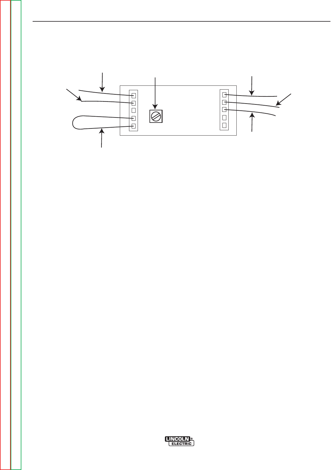
F-20F-20
PRECISION TIG 275
Return to Section TOC Return to Section TOC Return to Section TOC Return to Section TOC
Return to Master TOC Return to Master TOC Return to Master TOC Return to Master TOC
TROUBLESHOOTING & REPAIR
METER CALIBRATION ADJUSTMENTS (continued)
CALIBRATION CHECK
The Digital Meter Calibration Trimmer is located on the
back of the meter housing near the right side connec-
tor plug (with two leads and a jumper attached). This
trimmer adjusts calibration of the meter used for both
ammeter and voltmeter readings, so its calibration
should be checked first, as follows:
1. Set the TIG mode and, without closing the arc start
switch, preset the panel maximum output control so
the panel digital meter reads 200 amps.
2. Using a DC (avg.) digital test voltmeter with at least
0.5% accuracy at 1,000v, measure the DC voltage
between (+) pin 2 (lead #303) and (-) pin 1 (lead
#306) at the right side meter plug (nearest the trim-
mer).
3. This voltage should match the 200A panel meter
reading (as 0.200v, or 200mv) within 1%. If not,
adjust the trimmer so that the panel meter accuracy
is corrected. (See Figure F.1)
FIGURE F.1 – TRIMMER
TRIMMER
306 301
304B
302
303
JUMPER
Note: The Precision TIG meter circuits are factory calibrated for the accuracy of the ammeter and voltmeter and
should not need adjustment. However, the factory trimmers are accessible inside the control box:
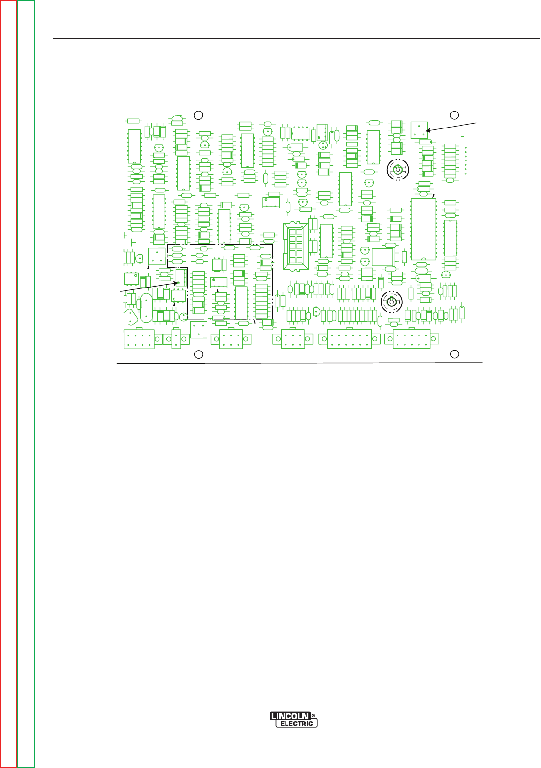
F-21F-21
PRECISION TIG 275
Return to Section TOC Return to Section TOC Return to Section TOC Return to Section TOC
Return to Master TOC Return to Master TOC Return to Master TOC Return to Master TOC
TROUBLESHOOTING & REPAIR
AMMETER CALIBRATION PROCEDURE
1. Locate the Ammeter Calibration Trimmer (R5). See
Figure F.1.
2. Set to TIG mode with DC polarity and LOCAL con-
trol. Without closing the arc start switch, preset the
maximum output panel control so the panel digital
meter reads approx. 200 amps.
3. Using a DC (AVG.) test ammeter with at least 1%
accuracy at up to 300 amps, connect it to measure
the DC current through a short weld cable shorting
out the work(+) to electrode(-) studs on the front stud
panel. Remove the TIG torch if connected.
4. Close the arc start switch just long enough to com-
pare the panel meter reading to that of the test
ammeter. The short circuit current readings should
match within 4% +/-2A. If not, adjust the trimmer so
that the panel meter accuracy is corrected.
VOLTMETER CALIBRATION PROCEDURE
1. Locate the Voltmeter Calibration Trimmer (R2) on
the control board. See Figure F1.
2. To prevent maximum OCV output, disconnect the
SCR gate lead plug from receptacle J4.
3. Set to TIG mode with DC- polarity without closing the
arc start switch.
4. Using a DC (avg.) test voltmeter with at least 1%
accuracy at up to 100 volts, connect it across the
work (+) and electrode (-) studs on the front stud
panel. Remove the TIG torch, if connected.
5. Press the display panel switch to V (volts) position,
then close the arc start switch just long enough to
compare the panel meter reading to that of the test
volt meter. The open circuit voltage readings (about
50 VDC) should match within 3% +/-1v. If not, adjust
the trimmer so that the panel meter accuracy is cor-
rected.
NOTE: If the Arc Start switch is held closed longer than
about 15 seconds, the machine will shut down
to protect internal holding resistor from over-
heating.
METER CALIBRATION ADJUSTMENTS (continued)
X
X
X
X
X
X
X
X
X
X
X
X
X
X
XXX
XXX
X X X XX X X XX
X
X
X
X X X X X X
X X
X X X X X X
X X
X X
X X
X X
X X
X X X X
X
X
X
X
X
X
X
X
X
X
X X
DZ16
C47
R274
D58
R93
D21
X11
D65
C106
C35
Q17
D80
Q23
Q14
C31
R96
C128
C152
R318
R333
C76
R331
DZ22
D67
C155
R134
X10
R205
C34
C19
C45
C59
C87
R161
X16
R319
R102
C14
C124
D23
R282
C4
Y1
R38
R207
R279
C105
R1
DZ10
C71
R257
C157
R92
R166
R3
DZ15
J6
R203
R34
C17
R2
D62
Q9
R106
D22
D19
R175
R246
R168
R165
C146
R128
C30
C104
R269
Q16
R107
R10
R121
R176
R126
R95
R247
R320
OCI7R315
R78
C20
R292
R295
R65
J8
D6
D73
D31
R294
R76
R41
R308
D34
R293
R60
J9
DZ18
R6
R323
C57
R243
D90
C90
C15
R311
R173
R249
C12
R172
R94
DZ19
R71
R307
R267
C127
R317
C93
X7
R252
R162
C140
R61R75
R122
C88
C70
R321
R82
R334
R256
R325
R330
C107
R337
R314R335
R284
C103
D79
R364
R358
R12
C110
C49
D11
J5A
D82
R245
X4
R210
J7
C153
R248
R209
X17
C139
R275
R352
C85
D81
J2
C151
R98
R32
R204
Q27
C64
Q25
R28
R353
R174
D89
DZ20
R119
R322
J10
DZ17
C36
C56
R171
OCI6
R255
D2
R167
DZ25
R39
R259
R7
Q18
C18
C150
R100
R69
C109
R125
C108
R120
R26
DZ12
R251
R250
R356
C3
R285
D72
R281
C158
R64
R332
R36
Q19
C165
C148
D63
R163
C122
R309
R290
R336
R357
R270
C121
R253
R72
DZ9
C119
R276
C145
R361
R289
D55
R244
R310
C142
DZ4
C89
C29
C141
C125
R11
R81
C32
R169
R164
R62
R208
D5
C13
D24
R313
R104
C44
R131
X15
C48
C63
R67
C73
R277
R74
DZ2
R133
C123
R101
R271
R70
Q20
C147
R283
R327
R4
D83
R287
R291
C159
Q24
R73
R35
R99
C28
R268
R63
C156
R29
R123
C74D54
R312
R170
R40
C120
C102
R80
C77
C149
C5
R33
R339
C62
C60
X3
C46
R103
R258
C33
R351
C55
R206
C75
C126
C16
Q26
D20
R202
D42
R296
R77
X19
R286
R129
C86
R37
R135
DZ24
D64
R97
R273
R132
R124
X2
R66
C72
C91
R280
C154
R288
R328
C58
R68
C143
R130
DZ6
R31
DZ21
Q8
C61
D7
R278
C92
R211
DZ23
Q28
R5
R136
R27
R324
Q21
D30
R326
X14
R272
R91
R42
R338
R316
R254
C144
D41
R30
R79
D10
DZ11
X13
R212
R329
R105
D59
R127
R359
R-5
R-2
FIGURE F.2 - CONTROL BOARD TRIMMERS


F-23F-23
PRECISION TIG 275
Return to Section TOC Return to Section TOC Return to Section TOC Return to Section TOC
Return to Master TOC Return to Master TOC Return to Master TOC Return to Master TOC
TROUBLESHOOTING & REPAIR
HIGH FREQUENCY CIRCUIT DISABLE PROCEDURE
Service and repair should be performed by only Lincoln Electric factory trained personnel.
Unauthorized repairs performed on this equipment may result in danger to the technician
or machine operator and will invalidate your factory warranty. For your safety and to avoid
electrical shock, please observe all safety notes and precautions detailed throughout this
manual.
If for any reason you do not understand the test procedures or are unable to perform the
test/repairs safely, contact the Lincoln Electric Service Department for electrical trou-
bleshooting assistance before you proceed. Call 1-888-935-3877.
DESCRIPTION
This procedure will disable the high frequency circuit allowing the technician to take volt-
age measurements without the possibility of high frequency damage to his test equipment.
MATERIALS NEEDED
3/8” Nut Driver
Electrical Insulating Tape
WARNING
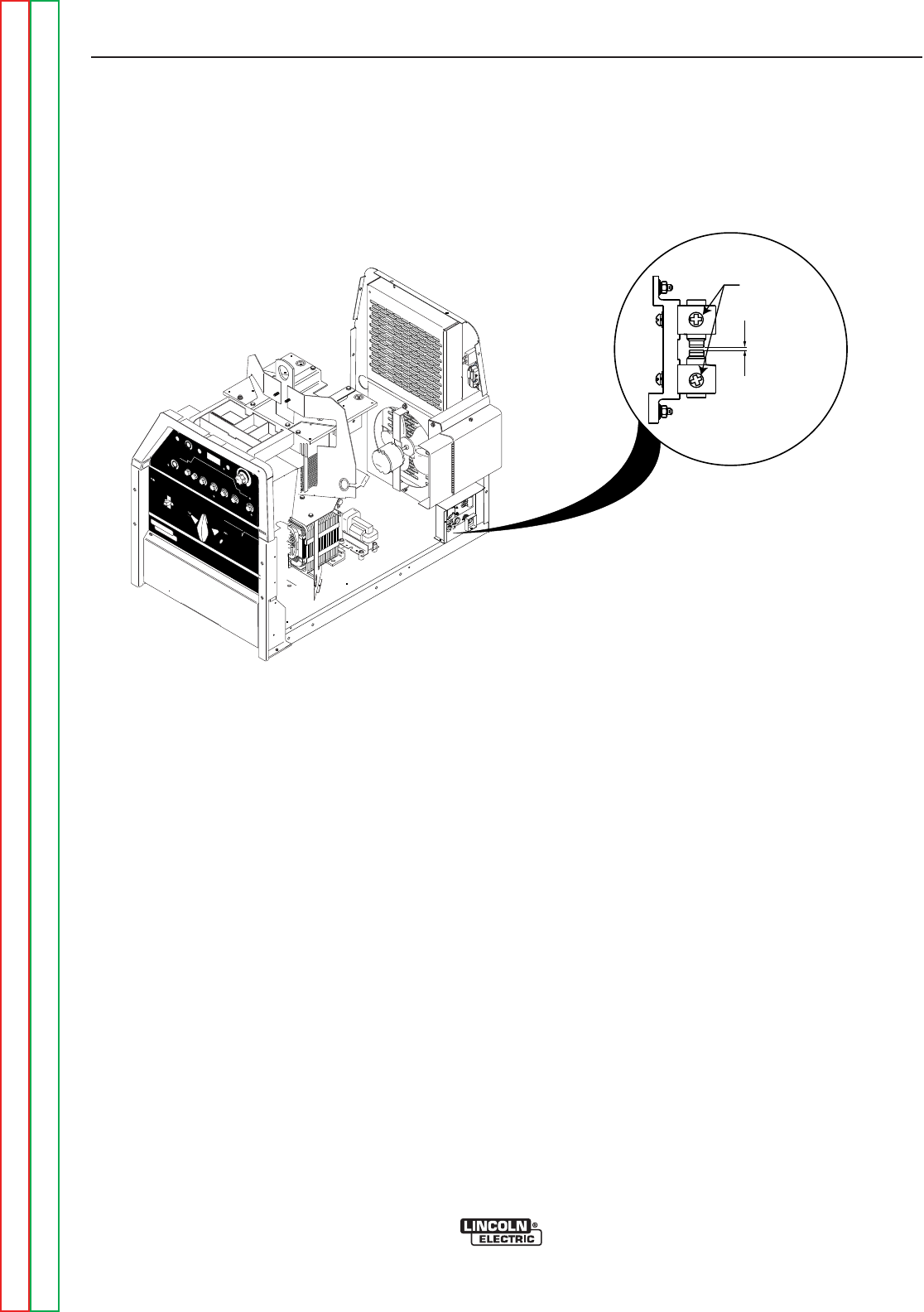
F-24F-24
PRECISION TIG 275
Return to Section TOC Return to Section TOC Return to Section TOC Return to Section TOC
Return to Master TOC Return to Master TOC Return to Master TOC Return to Master TOC
TROUBLESHOOTING & REPAIR
HIGH FREQUENCY CIRCUIT DISABLE PROCEDURE (continued)
PROCEDURE
1. Remove the input power to the PRECISION
TIG 275 machine.
2. Using the 3/8” nut driver, remove the right
side case cover.
3. Locate the Spark Gap Assembly at the lower
rear right side of the machine. See Figure
F.2.
4. Carefully remove the three leads from the
Spark Gap Assembly. See Figure F.2.
5. Insulate the leads from each other and from
the case.
6. When voltage testing and scope measure-
ments are complete, reconnect the three
leads to the Spark Gap Assembly.
7. Reassemble the right side case cover.
FIGURE F.2 – SPARK GAP ASSEMBLY
REMO
REMOTE
TE
LOCAL
LOCAL
MAXIMUM
MAXIMUM
DISPLA
DISPLAYY
MINIMUM
MINIMUM
MODE
MODE
AAC B
CBALANCE
ALANCEPOSTFLO
POSTFLOWW
DC
ON
OFF
POWER
AC
DC +
PRECISION TIGTM
375
THE LINCOLN ELECTRIC COMPANY CLEVELAND, OHIO USA
DO NOT SWITCH
WHILE WELDING
SQUARE WAVE POWER SOURCE
featuring ...MICRO START TM
TECHNOLOGY
~
WARNING
LINCOLN
ELECTRIC
!
.015 Spark Gap
LEADS
ATTACH
HERE
VIEWED FROM ABOVE

F-25F-25
PRECISION TIG 275
Return to Section TOC Return to Section TOC Return to Section TOC Return to Section TOC
Return to Master TOC Return to Master TOC Return to Master TOC Return to Master TOC
TROUBLESHOOTING & REPAIR
PROTECTION BOARD TEST
Service and repair should be performed by only Lincoln Electric factory trained personnel.
Unauthorized repairs performed on this equipment may result in danger to the technician
or machine operator and will invalidate your factory warranty. For your safety and to avoid
electrical shock, please observe all safety notes and precautions detailed throughout this
manual.
If for any reason you do not understand the test procedures or are unable to perform the
test/repairs safely, contact the Lincoln Electric Service Department for electrical trou-
bleshooting assistance before you proceed. Call 1-888-935-3877.
TEST DESCRIPTION
This procedure will determine if the Protection board is functioning properly.
MATERIALS NEEDED
3/8” Nut Driver
Voltmeter/Ohmmeter (Multimeter)
Tig 275 Wiring Diagrams
WARNING
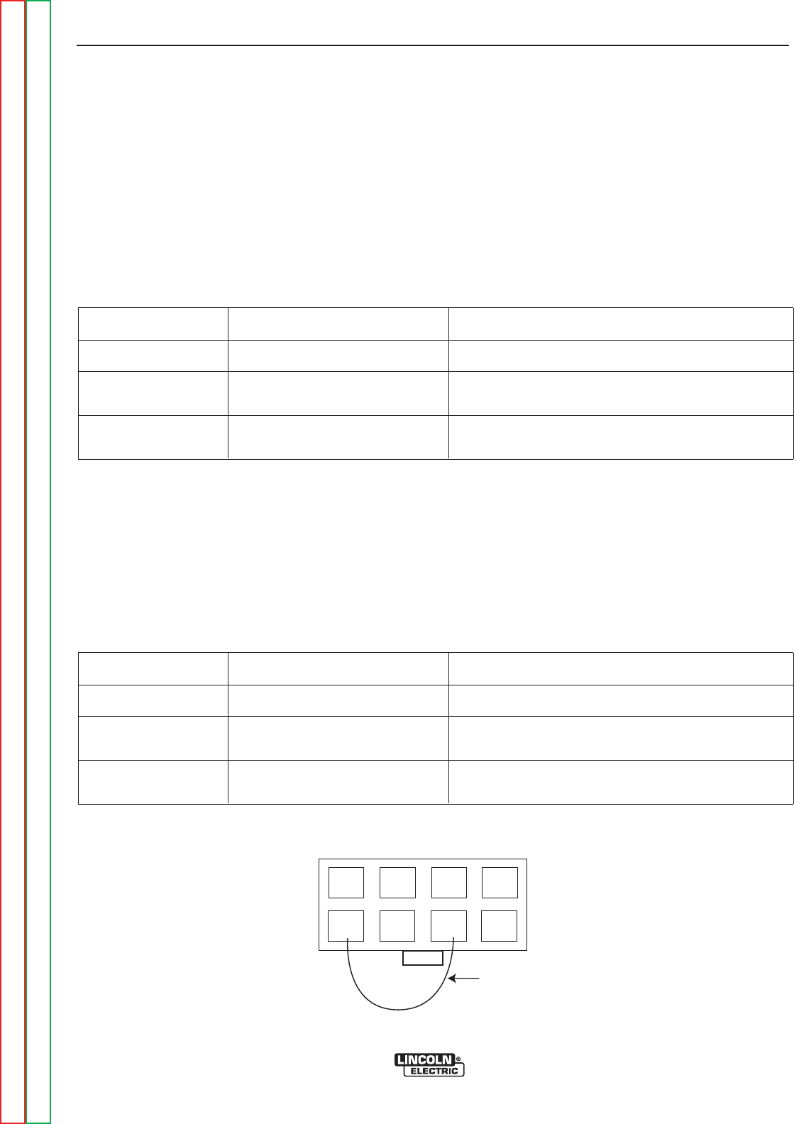
F-26F-26
PRECISION TIG 275
Return to Section TOC Return to Section TOC Return to Section TOC Return to Section TOC
Return to Master TOC Return to Master TOC Return to Master TOC Return to Master TOC
TROUBLESHOOTING & REPAIR
PROTECTION BOARD TEST (continued)
1. Using a 3/8” nut driver, remove the case top
and sides.
2. Check that P5 is connected to J5, not J5A.
See the Wiring Diagram.
3. Unplug P5 from the control board. Measure
resistance at P5. See Figure F3. See tables
below.
4. If the readings above are OK, the protection
board is OK. If not, go to step 5.
5. Unplug P23 from the protection board and
check continuity from P23 to P5. If OK, go
to step 6. See Wiring Diagram.
6. Unplug P22 from protection board. Measure
resistance at P22. See Tables.
7. If readings below are OK, protection board
is bad.
8. If readings below are wrong, remote amptrol
or remote receptacle is bad.
FIGURE F.3 – Plug J5 (viewed from pin end)
1
567
8
4
3
2
Jumper
Table F.1
Table F.2
RESISTANCE BETWEEN
Pins 5 & 7 Open when trigger open, short when trigger closed.
Increasing from 0 to 10K when working on remote
amptrol from min. to max.
Decreasing from 10K to 0 when working on remote
amptrol from min. to max.
TRIGGER
B-A
B-C Pins 3 & 4
Pins 2 & 3
READING
RESISTANCE BETWEEN
Pins 3 & 6 Open when trigger open, short when trigger closed.
Increasing from 0 to 10K when working on remote
amptrol from min. to max.
Decreasing from 10K to 0 when working on remote
amptrol from min. to max.
TRIGGER
B-A
B-C Pins 1 & 2
Pins 1 & 4
READING

F-27F-27
PRECISION TIG 275
Return to Section TOC Return to Section TOC Return to Section TOC Return to Section TOC
Return to Master TOC Return to Master TOC Return to Master TOC Return to Master TOC
TROUBLESHOOTING & REPAIR
T1 MAIN TRANSFORMER TEST
Service and repair should be performed by only Lincoln Electric factory trained personnel.
Unauthorized repairs performed on this equipment may result in danger to the technician
or machine operator and will invalidate your factory warranty. For your safety and to avoid
electrical shock, please observe all safety notes and precautions detailed throughout this
manual.
If for any reason you do not understand the test procedures or are unable to perform the
test/repairs safely, contact the Lincoln Electric Service Department for electrical trou-
bleshooting assistance before you proceed. Call 1-888-935-3877.
DESCRIPTION
This procedure will determine if the correct voltage is being applied to the primary of the
T1 transformer and also if the correct voltages are being induced on the secondary wind-
ings of the transformer.
MATERIALS NEEDED
3/8” Nut Driver
Voltmeter/Ohmmeter (Multimeter)
Tig 275 Wiring Diagrams
WARNING
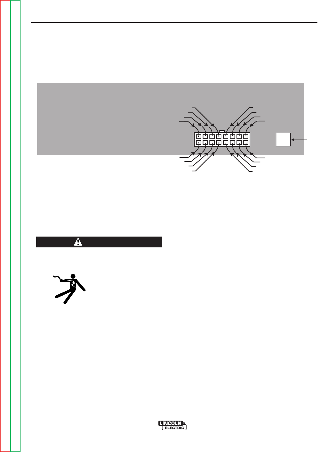
F-28F-28
PRECISION TIG 275
Return to Section TOC Return to Section TOC Return to Section TOC Return to Section TOC
Return to Master TOC Return to Master TOC Return to Master TOC Return to Master TOC
TROUBLESHOOTING & REPAIR
T1 MAIN TRANSFORMER TEST (continued)
TEST PROCEDURES
1. Using the 3/8” nut driver, remove the two screws
from the front control panel. Carefully lower the
panel. This will allow access to the control board.
2. Locate plug J11 on the control board. See Figure
F.4.
ELECTRIC SHOCK can kill.
*With input power ON, there are high voltages inside
the machine. Do not reach
into the machine or touch any
internal part.
...........................................................................
3. Carefully apply the correct input power making cer-
tain the reconnect configuration at the reconnect
panel is correct for the input voltage applied. Turn
the Precision TIG 275 ON.
4. Using the voltmeter, carefully test for the correct
transformer secondary voltages per Table F.3.
5. Carefully check for 63.5 VAC at leads 267 to lead
268. Lead 268 is located at the background rectifi-
er.
Note: Lead 267 is located at resistor R8. See Wiring
Diagram.
6. Carefully check for 115 VAC at leads 231 to 232.
Note: Lead 231 is located at the 115 VAC recepta-
cle on the back of the machine. Lead 232 is
located at the 15 amp circuit breaker CB1.
7. If all of the secondary voltages are correct, the T1
transformer is functioning properly.
a. If all of the secondary voltages are missing or
incorrect, make certain that the correct input
voltage is being applied to the correct primary
leads. See Table F.3.
b. If the correct input voltage is being applied to
the primary leads and any or all of the sec-
ondary voltages are incorrect, the T1 trans-
former may be faulty. Also check the leads for
broken or loose connections between plug J11
and the T1 transformer.
8. Replace the case side covers.
Figure F.4 Plug J11
263
214
204
210
266
253
270
220
209
262
265
201
252
269
271
213
Plug
J11
G3909
Plug
J11
WARNING

F-29F-29
PRECISION TIG 275
TROUBLESHOOTING & REPAIR
T1 MAIN TRANSFORMER TEST (continued)
Table F.3 - T1 Transformer Voltages
TEST POINTS ACCEPTABLE VOLTAGES
SECONDARY WINDINGS
PLUG J11 PIN 8 (LEAD W209)
TO
PLUG J11 PIN 16 (LEAD R210)
PLUG J11 PIN 7 (LEAD #201)
TO
PLUG J11 PIN 15 (LEAD #204)
X1 TO X2
PRIMARY WINDINGS
H1 TO H2
H1 TO H3
H1 TO H4
SECONDARY VOLTAGES
20 VAC
18VAC
78 VAC
PRIMARY VOLTAGES
208 VAC
230 VAC
460 VAC
NOTE: If the input voltages vary, the secondary voltages will vary accordingly.
Based on 208/230/460 models. For other voltage models refer to appropriate Wiring Diagram.
Return to Section TOC Return to Section TOC Return to Section TOC Return to Section TOC
Return to Master TOC Return to Master TOC Return to Master TOC Return to Master TOC


F-31F-31
PRECISION TIG 275
Return to Section TOC Return to Section TOC Return to Section TOC Return to Section TOC
Return to Master TOC Return to Master TOC Return to Master TOC Return to Master TOC
TROUBLESHOOTING & REPAIR
GAS (WATER) SOLENOID TEST
Service and repair should be performed by only Lincoln Electric factory trained personnel.
Unauthorized repairs performed on this equipment may result in danger to the technician
or machine operator and will invalidate your factory warranty. For your safety and to avoid
electrical shock, please observe all safety notes and precautions detailed throughout this
manual.
If for any reason you do not understand the test procedures or are unable to perform the
test/repairs safely, contact the Lincoln Electric Service Department for electrical trou-
bleshooting assistance before you proceed. Call 1-888-935-3877.
TEST DESCRIPTION
This procedure will help the technician to determine if the solenoid is receiving the correct
voltage also if the solenoid is functional.
MATERIALS NEEDED
3/8” Nut Driver
Voltmeter/Ohmmeter (Multimeter)
Isolated 115 VAC Power Supply
WARNING
F-32F-32
PRECISION TIG 275
Return to Section TOC Return to Section TOC Return to Section TOC Return to Section TOC
Return to Master TOC Return to Master TOC Return to Master TOC Return to Master TOC
TROUBLESHOOTING & REPAIR
GAS (WATER) SOLENOID TEST (continued)
TEST PROCEDURE
1. Remove input power to the Precision TIG
275 machine.
2. Remove the left case side.
3. Perform the High Frequency Circuit
Disable Procedure.
4. Locate the gas solenoid in the torch connec-
tion box.
5. Put the mode switch S3 in the 2-Step TIG
position.
ELECTRIC SHOCK CAN
KILL.
*With input power ON, there
are high voltages inside the
machine. Do not reach into
the machine or touch any
internal part.
6. Apply the correct input power to the TIG 275.
7. Activate the torch trigger and check for
approximately 115 VAC at the solenoid leads
(#231A and # 235). If the correct voltage is
present, the solenoid should activate and
gas should flow.
8. If voltage is present at leads #231A and
#235 and the solenoid does not activate, the
solenoid may be defective. The solenoid
can be further checked by removing leads
#231A and #235 from the solenoid and
applying the external isolated 115 VAC sup-
ply to the solenoid terminals. If the solenoid
activates with the external supply but not
when powered by the control board, the
problem may be in the control board. If you
hear solenoid activation but there is still no
gas flow, check for restrictions in the line.
9. When the test is complete, replace leads
#231A and #235.
10. Reassemble the two leads previously
removed in the High Frequency Circuit
Disable Procedure.
11. Reassemble the left case side.
12. If a water solenoid is used, it can be tested
using the same procedures.
WARNING

F-33F-33
PRECISION TIG 275
TROUBLESHOOTING & REPAIR
STATIC SCR TEST
Service and repair should be performed by only Lincoln Electric factory trained personnel.
Unauthorized repairs performed on this equipment may result in danger to the technician
or machine operator and will invalidate your factory warranty. For your safety and to avoid
electrical shock, please observe all safety notes and precautions detailed throughout this
manual.
If for any reason you do not understand the test procedures or are unable to perform the
test/repairs safely, contact the Lincoln Electric Service Department for electrical trou-
bleshooting assistance before you proceed. Call 1-888-935-3877.
DESCRIPTION
The SCR test is a quick check to determine if an SCR is “shorted” or “leaky”. See machine
waveform section for normal and abnormal SCR waveforms.
MATERIALS NEEDED
3/8” Nut Driver
Analog Ohmmeter (Multimeter)
Tig 275 Wiring Diagrams
SCR Heatsink Assembly Drawing
Return to Section TOC Return to Section TOC Return to Section TOC Return to Section TOC
Return to Master TOC Return to Master TOC Return to Master TOC Return to Master TOC
WARNING
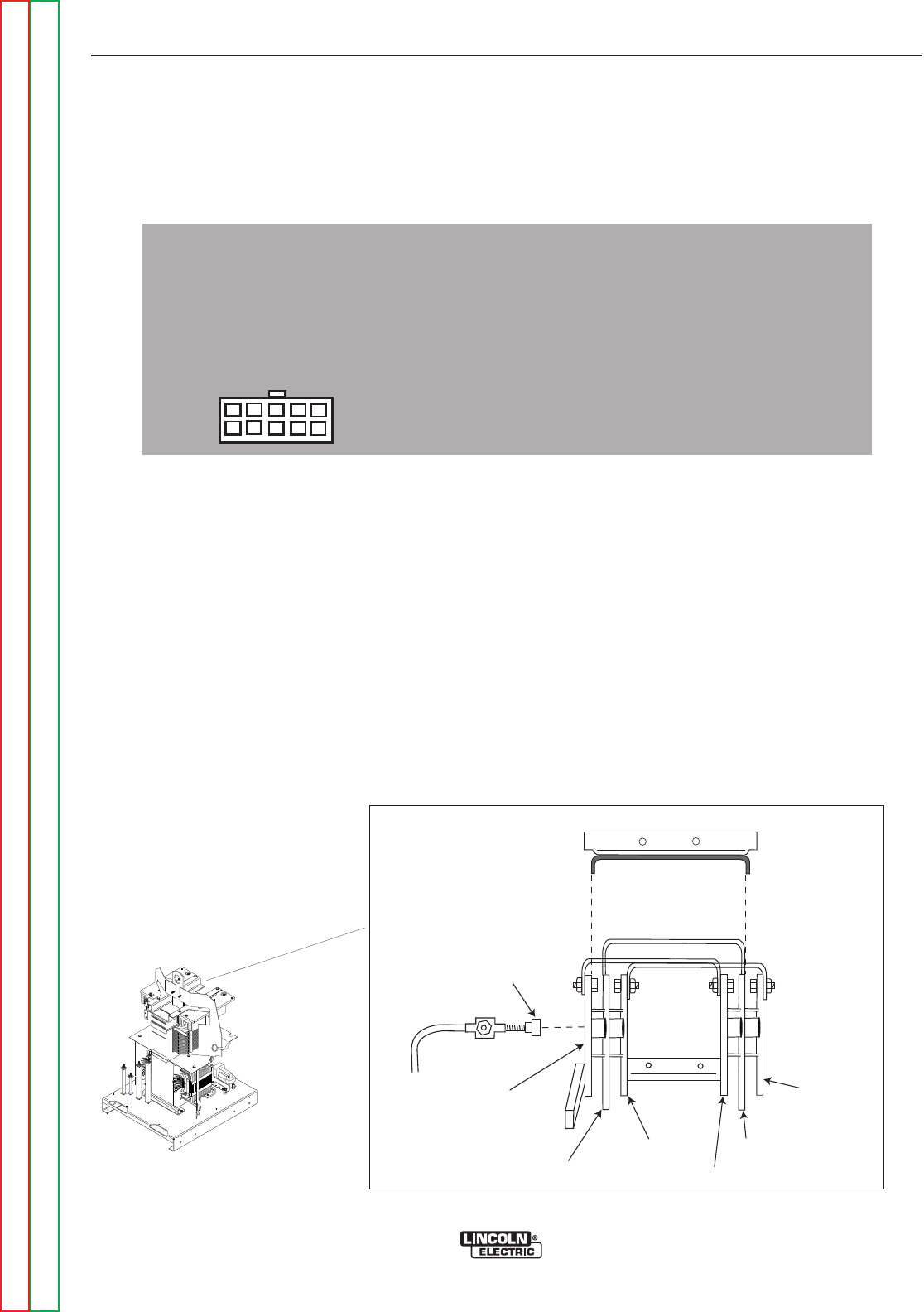
F-34F-34
PRECISION TIG 275
Return to Section TOC Return to Section TOC Return to Section TOC Return to Section TOC
Return to Master TOC Return to Master TOC Return to Master TOC Return to Master TOC
TROUBLESHOOTING & REPAIR
STATIC SCR TEST (continued)
TEST PROCEDURE
1. Remove main supply power to the PRECI-
SION TIG 275 and remove the case top and
left side.
2. Locate and remove plug J4 from the control
board. See Figure F.5.
3. Using an analog ohmmeter, test the resis-
tance from anode to cathode of SCR1.
Reverse the meter leads and check from
cathode to anode of SCR1. See Figure F.5. If
a low resistance is indicated in either direc-
tion, SCR1 is faulty. Replace the SCR Bridge
Assembly. See SCR Bridge Assembly
Removal and Replacement.
4. Repeat Step #3 testing SCR2, SCR3 and
SCR4.
5. To further check the SCRʼs functions, use an
SCR tester and proceed to the Active SCR
Test.
NOTE: Also check diode D1.
6. Replace plug J4 on the control board.
7. Replace the case top and left side.
Plug
J4
G3909
Figure F.5 - Plug J4 Location
DIODE D1
SCR4 CATHODE
SCR3 / SCR4 ANODE
SCR3 CATHODE
SCR2 ANODE
SCR1 / SCR2 CATHODE
SCR1 ANODE
LIFT BAIL STABILIZER
Figure F.6 - SCR TEST POINTS

F-35F-35
PRECISION TIG 275
TROUBLESHOOTING & REPAIR
ACTIVE SCR TEST
Service and repair should be performed by only Lincoln Electric factory trained personnel.
Unauthorized repairs performed on this equipment may result in danger to the technician
or machine operator and will invalidate your factory warranty. For your safety and to avoid
electrical shock, please observe all safety notes and precautions detailed throughout this
manual.
If for any reason you do not understand the test procedures or are unable to perform the
test/repairs safely, contact the Lincoln Electric Service Department for electrical trou-
bleshooting assistance before you proceed. Call 1-888-935-3877.
DESCRIPTION
The Active SCR test will determine if the device is able to be gated “ON” and conduct cur-
rent from anode to cathode.
MATERIALS NEEDED
3/8” Nut Driver
TIG 275 Wiring Diagrams
An SCR Tester as Outlined in this Procedure
Return to Section TOC Return to Section TOC Return to Section TOC Return to Section TOC
Return to Master TOC Return to Master TOC Return to Master TOC Return to Master TOC
WARNING

F-36F-36
PRECISION TIG 275
Return to Section TOC Return to Section TOC Return to Section TOC Return to Section TOC
Return to Master TOC Return to Master TOC Return to Master TOC Return to Master TOC
TROUBLESHOOTING & REPAIR
ACTIVE SCR TEST (continued)
TEST PROCEDURE
1. Remove main supply power to the PRECI-
SION TIG 275 machine.
2. Locate and remove plug J4 from the control
board. See Figure F.7.
3. Perform the following test for all four SCRs.
See Figure F.8.
4. Construct the circuit outline in Figure F.8.
One 6V lantern battery can be used. Resistor
values are +\- 10%. The voltmeter scale
should be approximately 0-5 or 0-10 volts.
5. Battery Test - Check the battery by shorting
leads (A) and (C) and then close switch SW-
1. Replace the battery if voltage is less than
4.5 volts.
Plug
J4
G3909
Figure F.7 - Plug J4 Location
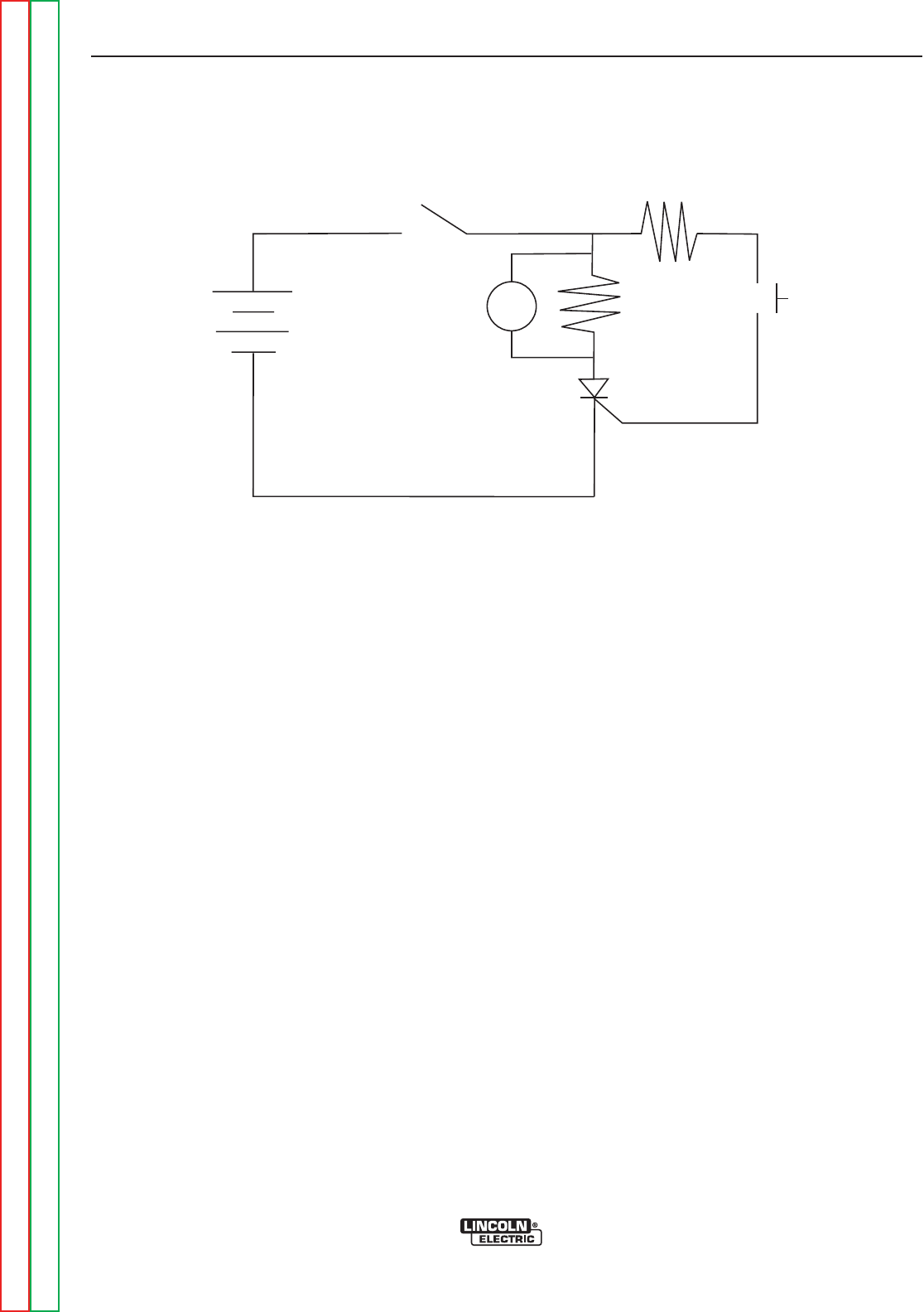
F-37F-37
PRECISION TIG 275
TROUBLESHOOTING & REPAIR
ACTIVE SCR TEST (continued)
SW2
R2
R1
V
A
G
C
SCR
under
test
6 volt
lantern
battery
+
SW1
Figure F.8 - Active SCR Test Set-Up
R1 = 4 ohms / 10 watts
R2 = 3 ohms / 10 watts
Resistor values are +/- 10%
Return to Section TOC Return to Section TOC Return to Section TOC Return to Section TOC
Return to Master TOC Return to Master TOC Return to Master TOC Return to Master TOC
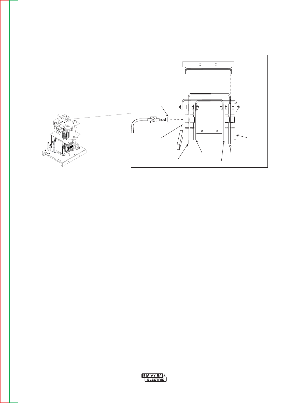
F-38F-38
PRECISION TIG 275
Return to Section TOC Return to Section TOC Return to Section TOC Return to Section TOC
Return to Master TOC Return to Master TOC Return to Master TOC Return to Master TOC
TROUBLESHOOTING & REPAIR
ACTIVE SCR TEST (continued)
6. Connect SCR into the test circuit as shown
in Figure F.8. (A)Lead to anode (C) lead to
cathode and (G) lead to the gate.
7. Close switch SW-1 (Switch SW-2 should be
open). The voltmeter should read zero. If
the voltmeter reads higher than zero, the
SCR is shorted.
8. With switch SW-1 closed, close switch SW-2
for two seconds and release. The voltmeter
should read 3 to 6 volts before and after
switch SW-2 is released. If the voltmeter
does not read, or reads only while SW-2 is
depressed, the SCR or battery is defective.
(Repeat Battery Test Procedure described in
Step 5.)
9. Open switch SW-1, disconnect the gate lead
(G) and reverse the (A) and (C) leads on
the SCR. Close switch SW-1. The voltmeter
should read zero. If the voltage is higher
than zero, the SCR is shorted.
10. Replace any SCRs that do not pass the
test. See SCR Bridge Assembly
Removal and Replacement.
11. Replace plug J4 on the control board.
12. Replace the case sides and top.
DIODE D1
SCR4 CATHODE
SCR3 / SCR4 ANODE
SCR3 CATHODE
SCR2 ANODE
SCR1 / SCR2 CATHODE
SCR1 ANODE
LIFT BAIL STABILIZER
Figure F.9 - SCR Gate Locations
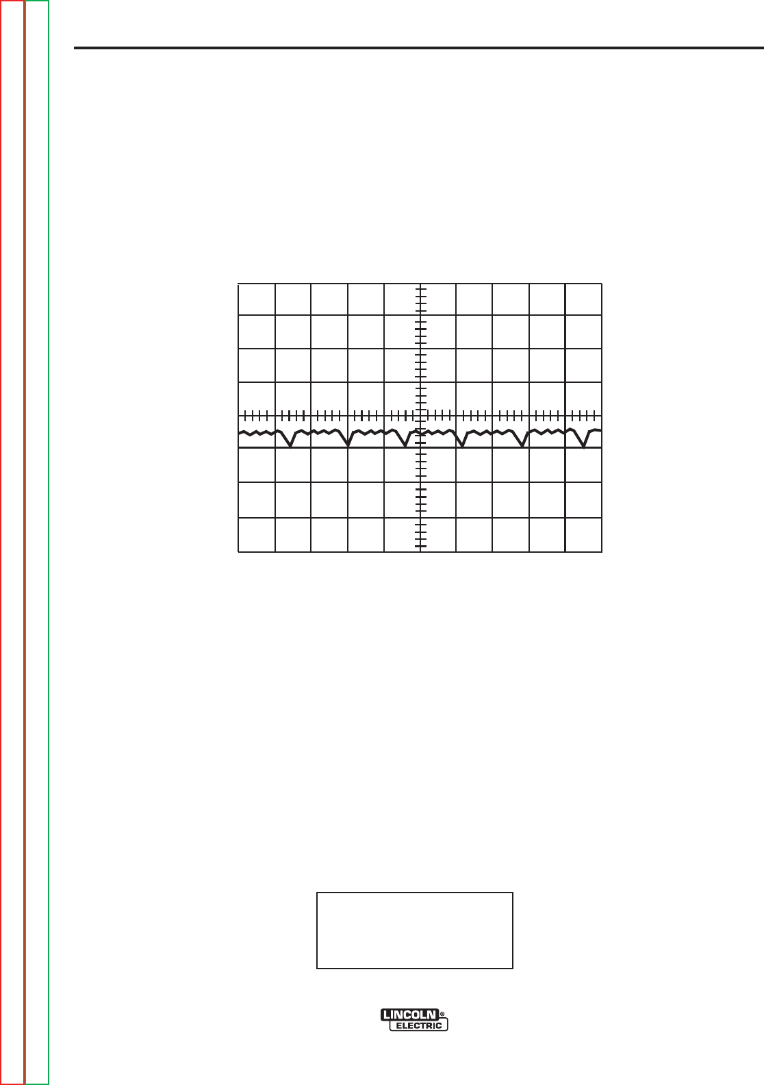
F-39
TROUBLESHOOTING & REPAIR
F-39
PRECISION TIG 275
Return to Section TOC Return to Section TOC Return to Section TOC Return to Section TOC
Return to Master TOC Return to Master TOC Return to Master TOC Return to Master TOC
0V
5 ms
20V
TYPICAL OUTPUT VOLTAGE WAVEFORM - MACHINE LOADED TO 2 AMPS
DC - TIG MODE
HIGH VOLTAGE/ HIGH FREQUENCY can damage test equipment.
Perform all voltage and waveform checks with high frequency circuit OFF.
Perform High Frequency Disable Procedure.
This is the typical AC output voltage
waveform generated from a properly
operating machine. Note that each ver-
tical division represents 20 volts and
that each horizontal division represents
5 milliseconds in time.
NOTE: Scope probes connected at
machine output terminals: (+) probe to
electrode, (-) probe to work.
Volts/Div......................20V/Div.
Horizontal Sweep......5 ms/Div.
Coupling..............................DC
Trigger..........................Internal
SCOPE SETTINGS
AC BALANCE CONTROL IN “AUTO”
OUTPUT CONTROL AT MINIMUM
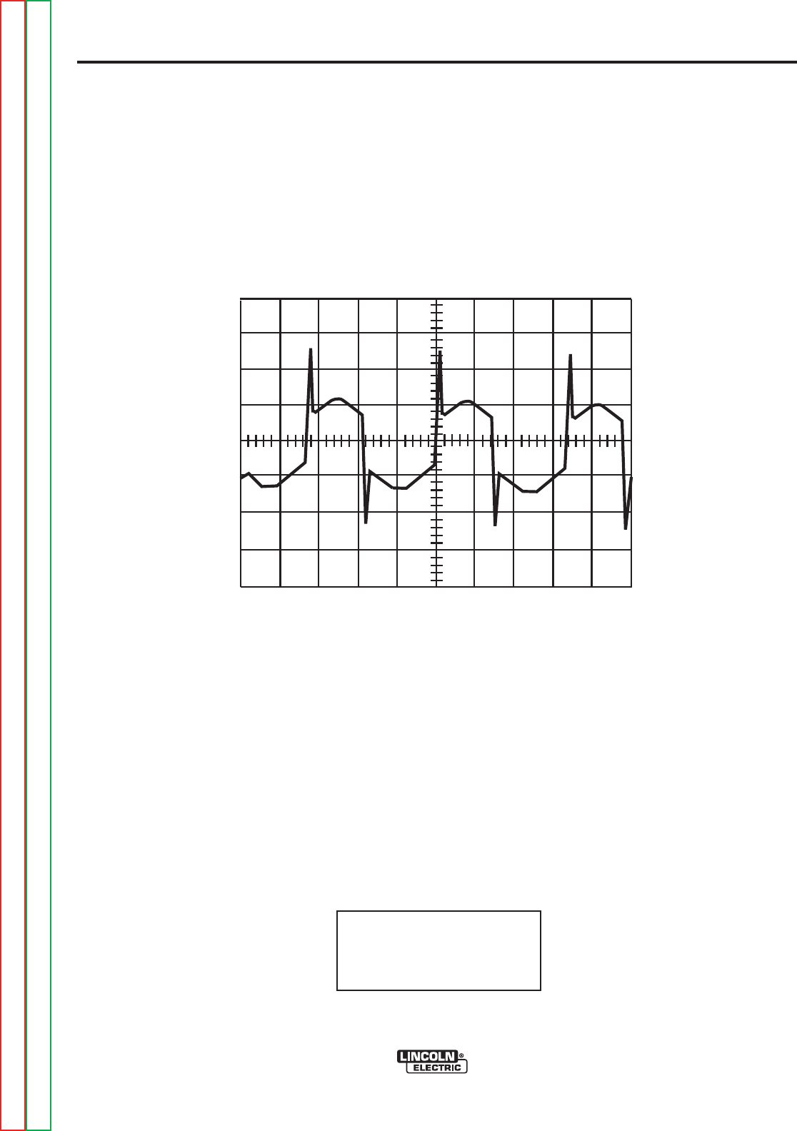
F-40F-40
PRECISION TIG 275
TROUBLESHOOTING & REPAIR
0V
5 ms
20V
TYPICAL OUTPUT VOLTAGE WAVEFORM - MACHINE LOADED TO 200 AMPS
AC - TIG MODE
HIGH VOLTAGE/ HIGH FREQUENCY can damage test equipment.
Perform all voltage and waveform checks with high frequency circuit OFF.
Perform High Frequency Disable Procedure.
This is the typical AC output voltage
waveform generated from a properly
operating machine. Note that each ver-
tical division represents 20 volts and
that each horizontal division represents
5 milliseconds in time. The machine
was loaded with a resistance grid bank.
NOTE: Scope probes connected at
machine output terminals: (+) probe to
electrode, (-) probe to work.
Volts/Div......................20V/Div.
Horizontal Sweep......5 ms/Div.
Coupling..............................DC
Trigger..........................Internal
SCOPE SETTINGS
AC BALANCE CONTROL IN “AUTO”
Return to Section TOC Return to Section TOC Return to Section TOC Return to Section TOC
Return to Master TOC Return to Master TOC Return to Master TOC Return to Master TOC
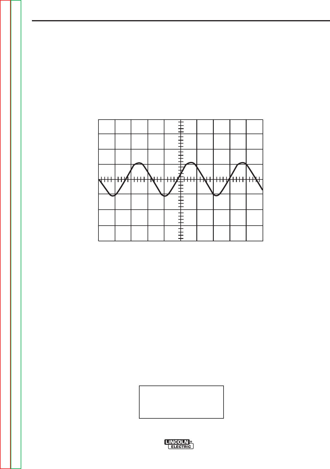
F-41F-41
PRECISION TIG 275
Return to Section TOC Return to Section TOC Return to Section TOC Return to Section TOC
Return to Master TOC Return to Master TOC Return to Master TOC Return to Master TOC
TROUBLESHOOTING & REPAIR
0V
5 ms
20V
TYPICAL AC VOLTAGE WAVEFORM - MACHINE LOADED TO 50 AMPS
AC - TIG MODE
HIGH VOLTAGE/ HIGH FREQUENCY can damage test equipment.
Perform all voltage and waveform checks with high frequency circuit OFF.
Perform High Frequency Disable Procedure.
This is the typical DC (+) output voltage
waveform generated from a properly
operating machine. Note that each ver-
tical division represents 20 volts and
that each horizontal division represents
5 milliseconds in time.
NOTE: Scope probes connected at
machine output terminals: (+) probe to
electrode, (-) probe to work.
Volts/Div......................20V/Div.
Horizontal Sweep......5 ms/Div.
Coupling..............................DC
Trigger..........................Internal
SCOPE SETTINGS
AC BALANCE CONTROL IN “AUTO”
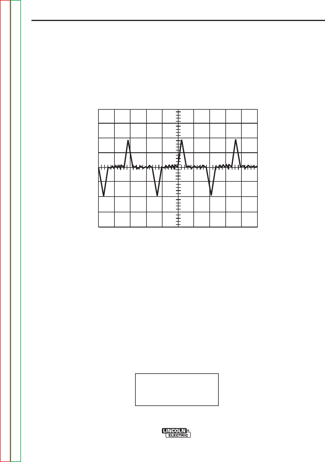
F-42F-42
PRECISION TIG 275
TROUBLESHOOTING & REPAIR
0V
5 ms
20V
TYPICAL AC VOLTAGE WAVEFORM - MACHINE LOADED TO 2 AMPS
AC - TIG MODE
HIGH VOLTAGE/ HIGH FREQUENCY can damage test equipment.
Perform all voltage and waveform checks with high frequency circuit OFF.
Perform High Frequency Disable Procedure.
This is the typical AC output voltage
waveform generated from a properly
operating machine. Note that each ver-
tical division represents 20 volts and
that each horizontal division represents
5 milliseconds in time.
NOTE: Scope probes connected at
machine output terminals: (+) probe to
electrode, (-) probe to work.
Volts/Div......................20V/Div.
Horizontal Sweep......5 ms/Div.
Coupling..............................DC
Trigger..........................Internal
SCOPE SETTINGS
AC BALANCE CONTROL IN “AUTO”
OUTPUT CONTROL AT MINIMUM.
Return to Section TOC Return to Section TOC Return to Section TOC Return to Section TOC
Return to Master TOC Return to Master TOC Return to Master TOC Return to Master TOC
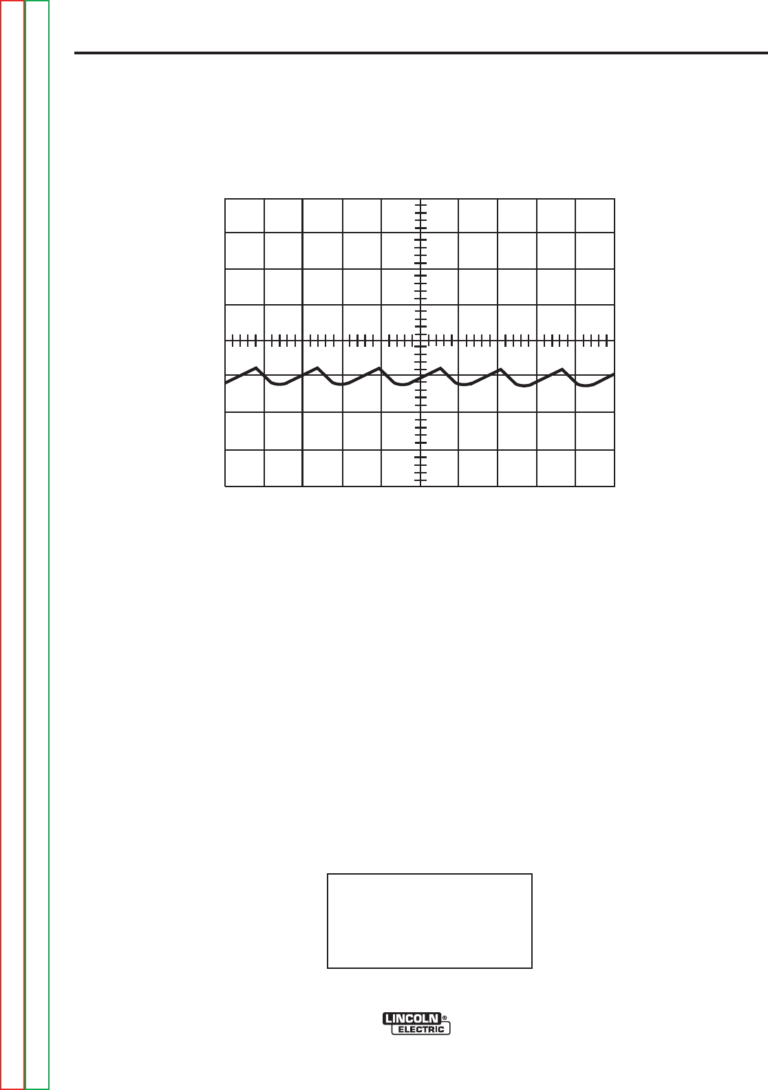
F-43F-43
PRECISION TIG 275
Return to Section TOC Return to Section TOC Return to Section TOC Return to Section TOC
Return to Master TOC Return to Master TOC Return to Master TOC Return to Master TOC
TROUBLESHOOTING & REPAIR
0V
5 ms
20V
This is the typical AC output voltage
waveform generated from a properly
operating machine. Note that each ver-
tical division represents 20 volts and
that each horizontal division represents
5 milliseconds in time.
NOTE: Scope probes connected at
machine output terminals: (+) probe to
electrode, (-) probe to work.
NOTE: AC balance control set at
“Balanced” position.
TYPICAL OUTPUT VOLTAGE WAVEFORM - MACHINE LOADED TO 200 AMPS
DC - TIG MODE
HIGH VOLTAGE/ HIGH FREQUENCY can damage test equipment.
Perform all voltage and waveform checks with high frequency circuit OFF.
Perform High Frequency Disable Procedure.
Volts/Div......................20V/Div.
Horizontal Sweep......5 ms/Div.
Coupling..............................DC
Trigger..........................Internal
SCOPE SETTINGS


F-45F-45
PRECISION TIG 275
Return to Section TOC Return to Section TOC Return to Section TOC Return to Section TOC
Return to Master TOC Return to Master TOC Return to Master TOC Return to Master TOC
TROUBLESHOOTING & REPAIR
HIGH VOLTAGE TRANSFORMER REMOVAL AND REPLACEMENT
Service and repair should be performed by only Lincoln Electric factory trained personnel.
Unauthorized repairs performed on this equipment may result in danger to the technician
or machine operator and will invalidate your factory warranty. For your safety and to avoid
electrical shock, please observe all safety notes and precautions detailed throughout this
manual.
If for any reason you do not understand the test procedures or are unable to perform the
test/repairs safely, contact the Lincoln Electric Service Department for electrical trou-
bleshooting assistance before you proceed. Call 1-888-935-3877.
DESCRIPTION
This procedure will aid the technician in the removal and replacement of the high voltage
transformer.
MATERIALS NEEDED
3/8” Nut Driver
7/16” Nut Driver
Phillips Head Screwdriver (Off-set)
Wire Cutters
WARNING
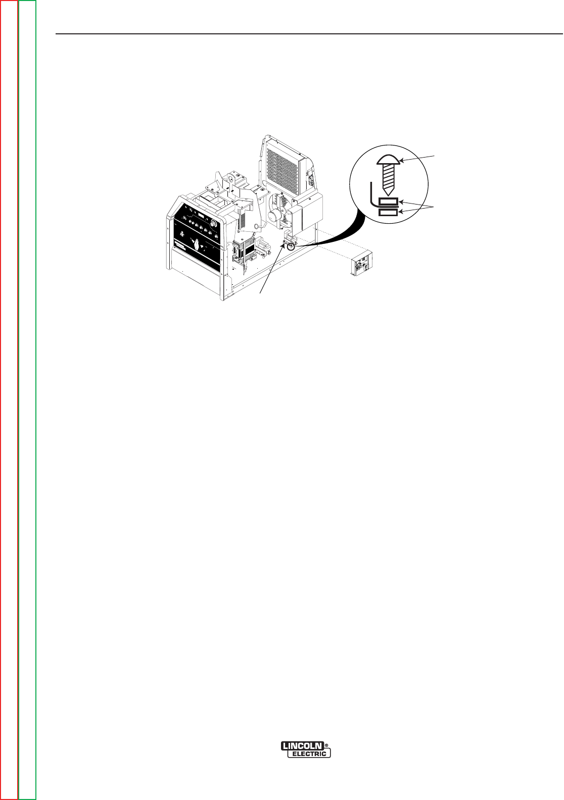
F-46F-46
PRECISION TIG 275
TROUBLESHOOTING & REPAIR
HIGH VOLTAGE TRANSFORMER
REMOVAL AND REPLACEMENT (continued)
REMOVAL PROCEDURE
1. Remove input power to the TIG 275
machine.
2. Using the 3/8” nut driver, remove the case
sides and top.
3. Using a 3/8” nut driver, remove the case
back.
Note: The case back will be connected to
the fan assembly and will have leads
connected to it, so just set aside.
4. Cut any necessary cable ties.
5. Disconnect black lead from the high voltage
transformer connecting to leads 231D and
231E.
6. Disconnect the black lead from the high
voltage transformer connecting to the
capacitor. It may be necessary to cut lead.
7. Using a 7/16” nut driver disconnect heavy
black leads S and F. See Figure F.11.
8. Using a 3/8” nut driver, remove the screw
securing the spark gap assembly box. See
Figure F.11. This will allow access to the
high voltage transformer mounting screws.
9. Using an off set phillips head screw driver,
remove the four high voltage transformer
mounting screws. Note insulator position-
ing. See Figure F.10.
10. Remove the high voltage transformer.
REPLACEMENT PROCEDURE
1. Replace the high voltage transformer.
2. Secure the new transformer using the four
phillips head mounting screws. Refer to
Figure F10 for insulator location.
3. Replace the 3/8” screw securing the spark
gap assembly box.
4. Reconnect leads S and F.
5. Reconnect high voltage transformer lead to
the capacitor.
6. Reconnect leads 231D and 231E to single
black lead.
7. Replace any necessary cable ties.
8. Secure the case back using the 3/8” mount-
ing bolts previously removed.
9. Replace the case sides and top.
REMO
REMOTE
TE
LOCAL
LOCAL
MAXIMUM
MAXIMUM
DISPLA
DISPLAYY
MINIMUM
MINIMUM
MODE
MODE
AAC B
CBALANCE
ALANCEPOSTFLO
POSTFLOWW
DC
ON
OFF
POWER
AC
DC +
PRECISION TIGTM
375
THE LINCOLN ELECTRIC COMPANY CLEVELAND, OHIO USA
DO NOT SWITCH
WHILE WELDING
SQUARE WAVE POWER SOURCE
featuring ...MICRO START TM
TECHNOLOGY
~
WARNING
LINCOLN
ELECTRIC
!
MOUNTING SCREW
INSULATORS
HIGH VOLTAGE
TRANSFORMER
Figure F.10 - High Voltage Transformer
Return to Section TOC Return to Section TOC Return to Section TOC Return to Section TOC
Return to Master TOC Return to Master TOC Return to Master TOC Return to Master TOC
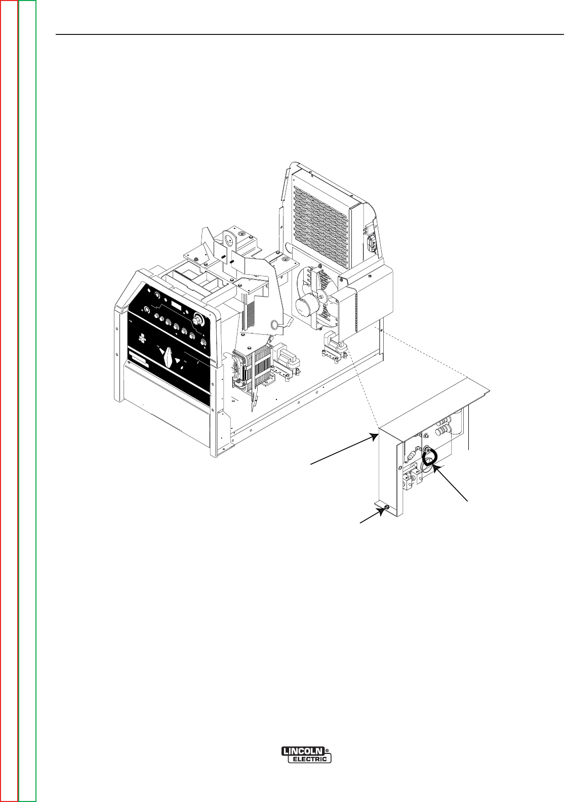
F-47F-47
PRECISION TIG 275
Return to Section TOC Return to Section TOC Return to Section TOC Return to Section TOC
Return to Master TOC Return to Master TOC Return to Master TOC Return to Master TOC
TROUBLESHOOTING & REPAIR
HIGH VOLTAGE TRANSFORMER
REMOVAL AND REPLACEMENT (continued)
REMO
REMOTE
TE
LOCAL
LOCAL
MAXIMUM
MAXIMUM
DISPLA
DISPLAY
Y
MINIMUM
MINIMUM
MODE
MODE
A
AC B
CBALANCE
ALANCE POSTFLO
POSTFLOWW
DC
ON
OFF
POWER
AC
DC +
PRECISION TIGTM
375
THE LINCOLN ELECTRIC COMPANY CLEVELAND, OHIO USA
DO NOT SWITCH
WHILE WELDING
SQUARE WAVE POWER SOURCE
featuring ...MICRO START TM
TECHNOLOGY
~
WARNING
LINCOLN
ELECTRIC
!
SPARK GAP
ASSEMBLY BOX
LEADS S & F
3/8" SCREW
Figure F.11 - 3/8” Screw & Leads S and F Locations


F-49F-49
PRECISION TIG 275
Return to Section TOC Return to Section TOC Return to Section TOC Return to Section TOC
Return to Master TOC Return to Master TOC Return to Master TOC Return to Master TOC
TROUBLESHOOTING & REPAIR
CONTROL BOARD REMOVAL AND REPLACEMENT
Service and repair should be performed by only Lincoln Electric factory trained personnel.
Unauthorized repairs performed on this equipment may result in danger to the technician
or machine operator and will invalidate your factory warranty. For your safety and to avoid
electrical shock, please observe all safety notes and precautions detailed throughout this
manual.
If for any reason you do not understand the test procedures or are unable to perform the
test/repairs safely, contact the Lincoln Electric Service Department for electrical trou-
bleshooting assistance before you proceed. Call 1-888-935-3877.
DESCRIPTION
This procedure will aid the technician in the removal and replacement of the control board.
MATERIALS NEEDED
3/8” Nut Driver
Phillips Head Screwdriver
Wire Cutters
WARNING
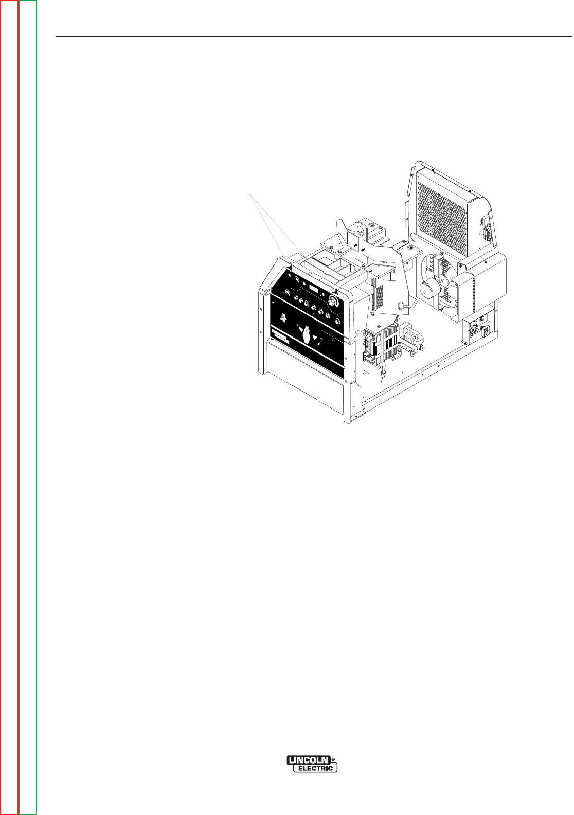
F-50F-50
PRECISION TIG 275
TROUBLESHOOTING & REPAIR
CONTROL BOARD REMOVAL AND REPLACEMENT (continued)
REMOVAL PROCEDURE
1. Remove input power to the TIG 275
machine.
2. Using a 3/8” nut driver, remove the two
screws from the top of the case front. See
Figure F.12.
3. The top front control box cover can now be
tilted forward to gain access to the control
board and its plugs.
4. From left to right, label and disconnect plugs
J4, J5, J6, J8, J9, J10, J11, J12. See Figure
F.13.
5. Cut any necessary cable ties.
6. Using a phillips head screwdriver, remove
the eight P.C. Board mounting screws. See
Figure F.13.
7. Carefully maneuver the control board out of
the front of the machine.
REPLACEMENT PROCEDURE
1. Replace the control board.
2. Mount the new control board in its proper
position using the eight phillips head mount-
ing screws.
3. Replace any necessary cable ties.
4. Reconnect plugs previously removed from
the control board.
5. Secure the control box assembly using the
two 3/8” mounting screws previously
removed.
REMO
REMOTE
TE
LOCAL
LOCAL
MAXIMUM
MAXIMUM
DISPLA
DISPLAYY
MINIMUM
MINIMUM
MODE
MODE
A
AC B
CBALANCE
ALANCEPOSTFLO
POSTFLOWW
DC
ON
OFF
POWER
AC
DC +
PRECISION TIGTM
375
THE LINCOLN ELECTRIC COMPANY CLEVELAND, OHIO USA
DO NOT SWITCH
WHILE WELDING
SQUARE WAVE POWER SOURCE
featuring ...MICRO START TM
TECHNOLOGY
~
WARNING
LINCOLN
ELECTRIC
!
CASEFRONT SCREWS
Figure F.12 - Case Front Screw Location
Return to Section TOC Return to Section TOC Return to Section TOC Return to Section TOC
Return to Master TOC Return to Master TOC Return to Master TOC Return to Master TOC
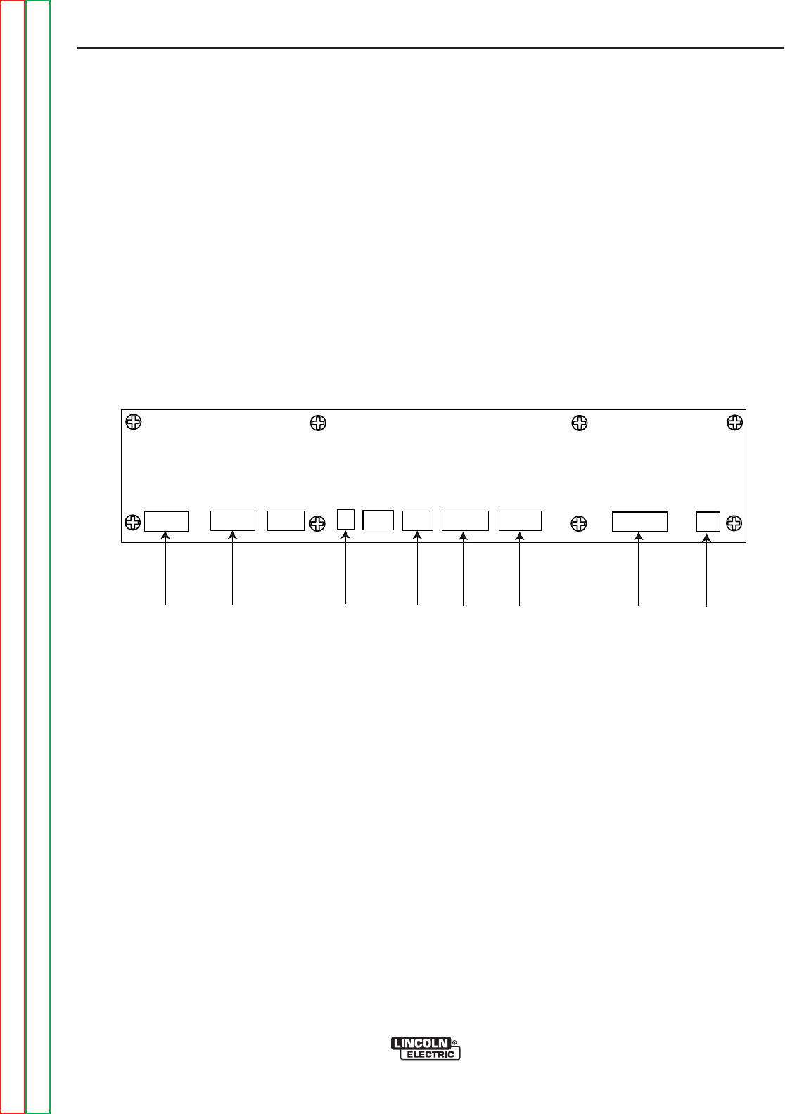
F-51F-51
PRECISION TIG 275
Return to Section TOC Return to Section TOC Return to Section TOC Return to Section TOC
Return to Master TOC Return to Master TOC Return to Master TOC Return to Master TOC
TROUBLESHOOTING & REPAIR
CONTROL BOARD REMOVAL AND REPLACEMENT (continued)
J12
J11J10J9
J8
J6
J5
J4
Figure F.13 - Control Board Plug Locations


F-53F-53
PRECISION TIG 275
Return to Section TOC Return to Section TOC Return to Section TOC Return to Section TOC
Return to Master TOC Return to Master TOC Return to Master TOC Return to Master TOC
TROUBLESHOOTING & REPAIR
SCR BRIDGE ASSEMBLY REMOVAL AND REPLACEMENT
Service and repair should be performed by only Lincoln Electric factory trained personnel.
Unauthorized repairs performed on this equipment may result in danger to the technician
or machine operator and will invalidate your factory warranty. For your safety and to avoid
electrical shock, please observe all safety notes and precautions detailed throughout this
manual.
If for any reason you do not understand the test procedures or are unable to perform the
test/repairs safely, contact the Lincoln Electric Service Department for electrical trou-
bleshooting assistance before you proceed. Call 1-888-935-3877.
DESCRIPTION
This procedure will aid the technician in the removal and replacement of the SCR bridge
for maintenance or replacement.
MATERIALS NEEDED
3/8” Nut Driver
1/2” Nut Driver
7/16” Nut Driver
Pliers
Crimp Wire Cutters
WARNING

F-54F-54
PRECISION TIG 275
TROUBLESHOOTING & REPAIR
SCR BRIDGE ASSEMBLY REMOVAL AND REPLACEMENT (continued)
REMOVAL PROCEDURE
1. Remove input power to the TIG 275
machine.
2. Using the 3/8” nut driver, remove the case
sides and top.
3. Label and cut leads G1 and G2. See
Figure F.14.
4. Label and cut leads G3 and G4. See
Figure F.14.
5. Remove the 1/2 “ nut securing leads B and
217. See Figure F.14.
6. Using a 7/16” nut driver, disconnect Pos.
lead and lead 218.See Figure F.14.
7. Using a 1/2” nut driver, disconnect Pos.
lead and lead 218. See Figure F.14.
8. Using a 1/2” nut driver, remove lead 216
and aluminum lead X1 connecting to the
main transformer. See Figure F.14. Note
washer placement upon removal.
9. Using a 1/2” nut driver, disconnect lead
220A and shunt from the output bridge. See
Figure F.14.
10. Using a 3/8” nut driver, remove the four
SCR bridge mounting bolts. Note insulator
washer placement upon removal.
REPLACEMENT PROCEDURE
1. Replace the SCR bridge.
2. Replace the four SCR bridge mounting
bolts previously removed.
Note: Be sure to replace insulating wash-
ers in their proper positions.
3. Reconnect lead 218 and Pos. lead previ-
ously removed.
4. Replace the shunt and lead 220A previous-
ly removed.
5. Replace the 1/2” bolt securing lead 216 and
the aluminum lead X1 originating from the
main transformer.
6. Reconnect the negative lead to the free
wheeling diode.
7. Replace the 1/2” bolt securing leads B and
217 previously removed.
8. Reconnect leads G1, G2, G3, and G4.
Splice, solder and insulate as necessary.
9. Replace case sides and top.
Return to Section TOC Return to Section TOC Return to Section TOC Return to Section TOC
Return to Master TOC Return to Master TOC Return to Master TOC Return to Master TOC
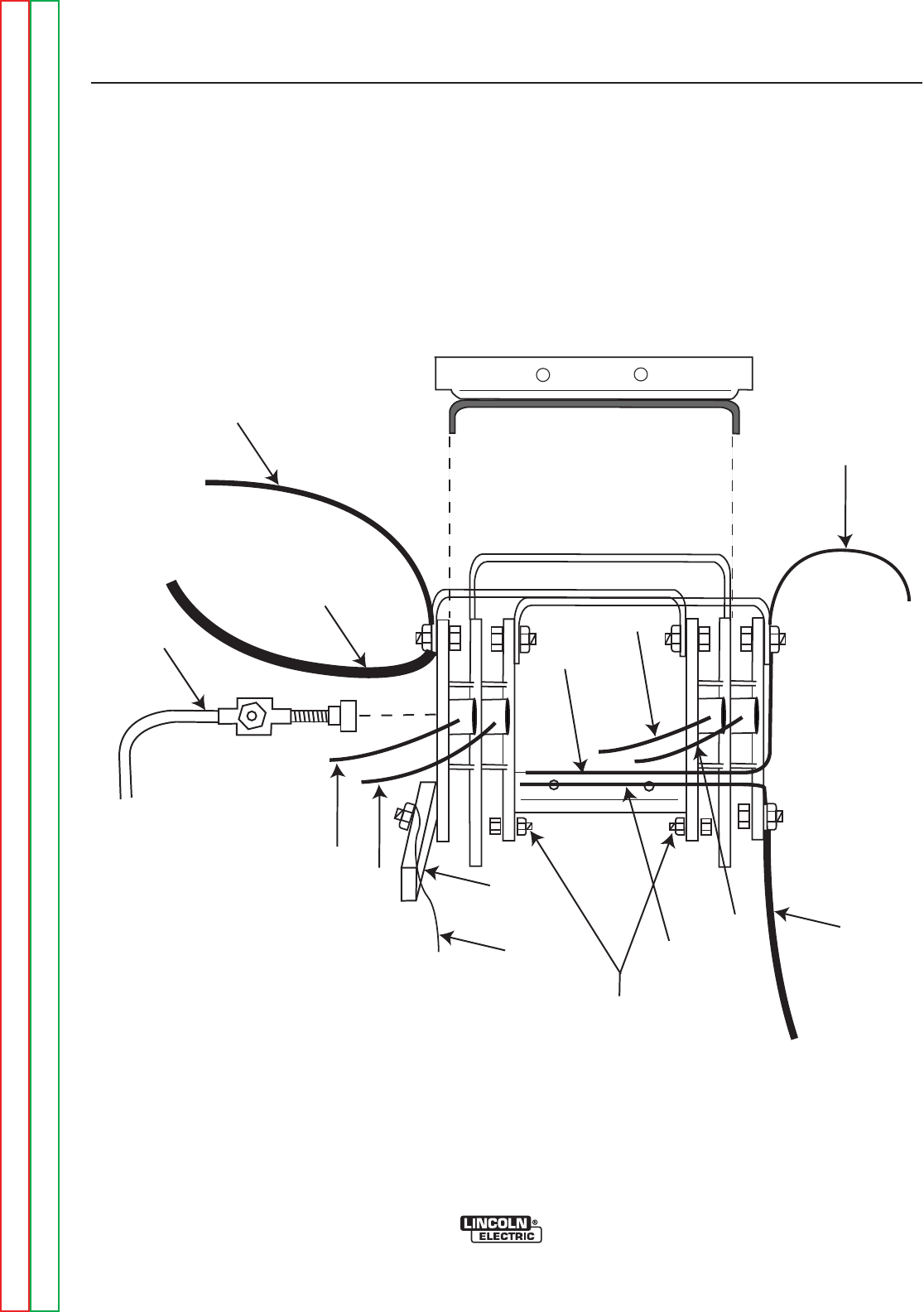
F-55F-55
PRECISION TIG 275
Return to Section TOC Return to Section TOC Return to Section TOC Return to Section TOC
Return to Master TOC Return to Master TOC Return to Master TOC Return to Master TOC
TROUBLESHOOTING & REPAIR
SCR BRIDGE REMOVAL AND REPLACEMENT (continued)
Negative
LIFT BAIL STABILIZER
217
B
G4
G3
G2
G1 Pos.
X1
Shunt
220A
Bridge
Mounting
Bolts
216
218
Figure F.14 - SCR BRIDGE CONNECTIONS

Return to Section TOC Return to Section TOC Return to Section TOC Return to Section TOC
Return to Master TOC Return to Master TOC Return to Master TOC Return to Master TOC
F-56F-56
TROUBLESHOOTING & REPAIR
MOUNTING OF STUD TYPE DIODES TO ALUMINUM HEAT SINKS (CONT’D)
DIODE STUD
SIZE
3/4 - 16
3/8 - 24
1/4 - 28
FOOT-
POUNDS
25-27
10±.5
INCH-
POUNDS
300-324
125+0/-5
22-25
PROCEDURE
1. Loosen the appropriate diode nut and remove the
diode that is to be replaced.
2. Clean the area on the heat sink around the diode
mounting surface using a putty knife, or similar
tool, DO NOT SCRATCH THE DIODE MOUNTING
SURFACE.
3. Polish each heat sink's mounting surface using
NO. 000 fine steel wool. Wipe surface clean with
a lint free cloth or paper towel.
4. Inspect the mounting surfaces of each new diode.
Remove all burrs and wipe clean. Do not use steel
wool or any abrasive cleanser on the diode
mounting surface.
5. Apply a thin (0.0003" to 0.0007") uniform layer of
E1868 (Dow Corning 340) heat sink compound to
the heat sink mounting surface.
a. Do not apply compound to diode stud or
mounting threads.
b. The diode threads must be clean and free of
defects so that the nut can be finger tightened
before applying torque. A "slip" type torque
wrench must be used to tighten the diode nut.
6. Tighten the diode nuts to the specifications in the
following table.
a. The nuts for diodes with steel studs are to be
started by hand and then torqued as per the
following table.
b. The nuts for diodes with copper studs are to
run on all the way by hand then torqued as per
the following table.
c. Turn a minimum of 1/2 turn more while
torquing per the table.
PRECISION TIG 375

F-57F-57
PRECISION TIG 275
Return to Section TOC Return to Section TOC Return to Section TOC Return to Section TOC
Return to Master TOC Return to Master TOC Return to Master TOC Return to Master TOC
TROUBLESHOOTING & REPAIR
POLARITY SWITCH REMOVAL AND REPLACEMENT
Service and repair should be performed by only Lincoln Electric factory trained personnel.
Unauthorized repairs performed on this equipment may result in danger to the technician
or machine operator and will invalidate your factory warranty. For your safety and to avoid
electrical shock, please observe all safety notes and precautions detailed throughout this
manual.
If for any reason you do not understand the test procedures or are unable to perform the
test/repairs safely, contact the Lincoln Electric Service Department for electrical trou-
bleshooting assistance before you proceed. Call 1-888-935-3877.
DESCRIPTION
This procedure will aid the technician in the removal and replacement of the polarity
switch.
MATERIALS NEEDED
3/8” Nut Driver
1/2” Wrench
7/16” Wrench
Phillips Head Screw Driver
Slot Head Screw Driver (2 Required)
WARNING
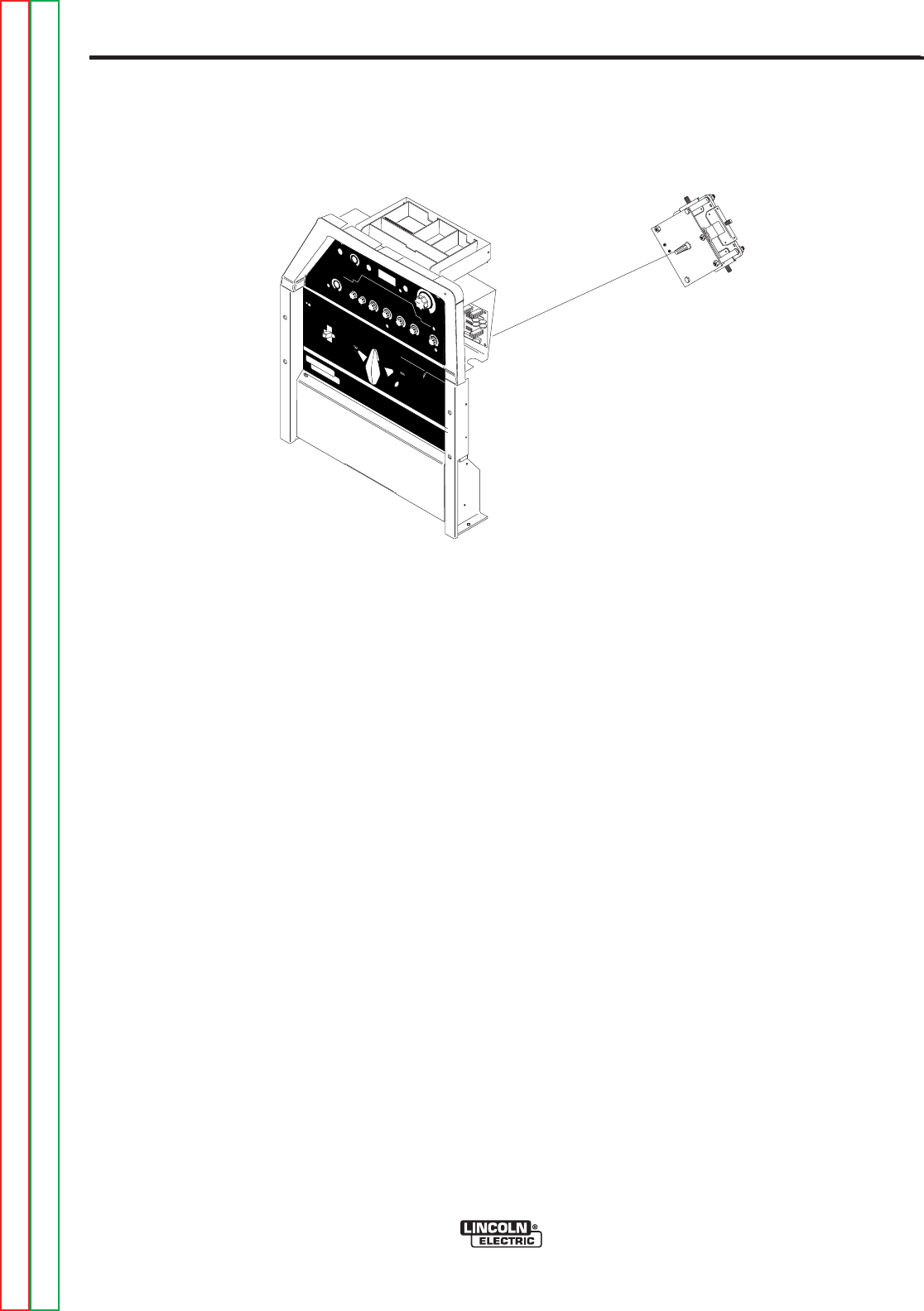
F-58F-58
PRECISION TIG 275
TROUBLESHOOTING & REPAIR
POLARITY SWITCH REMOVAL AND REPLACEMENT (continued)
REMOVAL PROCEDURE
1. Remove the input to the PRECISION TIG
275 machine.
2. Using the 3/8” nut driver, remove the case
sides and top.
3. Locate the polarity switch. See Figure F.15.
4. Using a 1/2”wrench label and disconnect
leads B,C,252, Pos, Neg, D2 diode assem-
bly,S,253, choke lead, X2 and all leads from
the main transformer. Be sure to label leads
for reassembly.
5. Disconnect leads 265 and 266A using quick
disconnects.
6. Using a phillips head screw driver, remove
the screw from the polarity switch handle.
See Figure F.15.
7. With the 2 slot head screw drivers, carefully
pry the polarity switch handle
8. Carefully peel back the lower nameplate on
the case front located around the polarity
switch to gain access to the polarity switch
mounting nuts.
NOTE: Do not remove the sticker completely.
9. Using a 7/16” nut driver remove the two
polarity switch mounting nuts located behind
the previously removed nameplate.
10. The polarity switch is ready for removal.
REPLACEMENT PROCEDURE
1. Replace the polarity switch.
2. Secure the polarity switch in its original posi-
tion with the 7/16” mounting nuts.
3. Firmly press the lower nameplate back into
its original position on the case front.
4. Press the polarity switch handle back onto
its shaft.
5. Secure polarity switch handle with the
phillips head screw previously removed.
6. Reconnect leads 265 and 266A previously
removed.
7. Reconnect all previously removed leads to
their proper terminals. See Wiring Diagram.
8. Replace case sides and top.
REMO
REMOTE
TE
LOCAL
LOCAL
MAXIMUM
MAXIMUM
DISPLA
DISPLAYY
MINIMUM
MINIMUM
MODEMODE
AAC B
CBALANCE
ALANCEPOSTFLO
POSTFLOW
W
DC
ON
OFF
POWER
AC
DC +
PRECISION TIGTM
375
THE LINCOLN ELECTRIC COMPANY CLEVELAND, OHIO USA
DO NOT SWITCH
WHILE WELDING
SQUARE WAVE POWER SOURCE
featuring ...MICRO START TM
TECHNOLOGY
~
WARNING
LINCOLN
ELECTRIC
!
Figure F.15 - Switch Location
Return to Section TOC Return to Section TOC Return to Section TOC Return to Section TOC
Return to Master TOC Return to Master TOC Return to Master TOC Return to Master TOC

F-59F-59
PRECISION TIG 275
Return to Section TOC Return to Section TOC Return to Section TOC Return to Section TOC
Return to Master TOC Return to Master TOC Return to Master TOC Return to Master TOC
TROUBLESHOOTING & REPAIR
SCR REMOVAL AND REPLACEMENT
Service and repair should be performed by only Lincoln Electric factory trained personnel.
Unauthorized repairs performed on this equipment may result in danger to the technician
or machine operator and will invalidate your factory warranty. For your safety and to avoid
electrical shock, please observe all safety notes and precautions detailed throughout this
manual.
If for any reason you do not understand the test procedures or are unable to perform the
test/repairs safely, contact the Lincoln Electric Service Department for electrical trou-
bleshooting assistance before you proceed. Call 1-888-935-3877.
DESCRIPTION
The following procedure will aid the technician in removing the SCRs from the output rec-
tifier heat sink for maintenance or replacement.
MATERIALS NEEDED
No. 000 Fine Steel Wool
Penetrox A-13 (Lincoln E2529) or Penetrox A
7/16” Open End Wrench
Allen Head Type Wrenches
WARNING
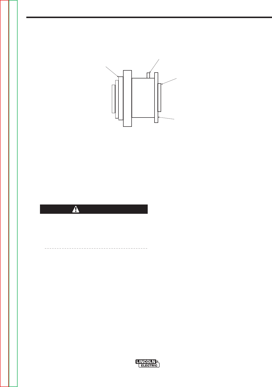
F-60F-60
PRECISION TIG 275
TROUBLESHOOTING & REPAIR
SCR REMOVAL AND REPLACEMENT (continued)
SPECIAL INSTRUCTIONS
NOTE: Before disassembling the existing recti-
fier, note toward which heat sink the outer
metal ring of the power SCR is mounted. Also,
note the positioning of the gate lead of the
SCR. Failure to reinstall the new SCR in the
same orientation as the original may result in
subsequent damage to the new SCR and
other components of the welder. See Figure
F.16.
The unclamping and clamping procedure out-
lined below is critical for the prevention of
internal SCR damage. Failure to follow this
procedure may result in subsequent damage
of the SCR. Handle all SCRs with care.
PROCEDURE
1. Remove the main input supply power to the
machine.
2. Perform the SCR/Diode Rectifier
Assembly Removal procedure.
3. Using a 7/16” open end wrench, alternately
loosen nuts 1/2 turn each until heat sinks
are loose. Remove nuts and leaf spring. IT
IS RECOMMENDED THAT NEW HARD-
WARE, LEAF SPRING AND HOUSING BE
USED FOR ASSEMBLY.
4. Remove the old SCR.
5. Clean the area on the heat sink around the
SCR mounting surface, using a putty knife
or similar tool. DO NOT SCRATCH THE
SCR MOUNTING SURFACE.
6. Polish each heat sinkʼs mounting surface
using NO.000 fine steal wool. Wipe surface
clean with a lint free cloth or paper towel.
7. Inspect the mounting surfaces of each new
SCR.
a. Remove all burrs and wipe clean. Do
not use steel wool or any abrasive
cleanser on the SCR mounting sur-
faces.
8. Apply a thin (0.001” to 0.003”) layer of
PENETROX A-13 (Lincoln Electric #E2529)
or PENTROX A, heat sink compound, to
each heat sinkʼs SCR mounting surface.
a. Care must be used to prevent foreign
material contamination of the SCR to
heat sink junction.
9. Place the new SCR between the heat
sinks. Be sure that the outer metal ring of
the SCR is facing toward the same heat
sink as the old SCRʼs metal ring. Be sure
that the roll pin of the heat sink engages
the “hole” in the SCR. The SCR contact
surfaces must sit flat against both heat sink
surfaces.
10. Perform the SCR/Diode Rectifier
Assembly Replacement Procedure.
11. Replace the case sides and top.
Cathode
Gate
Anode
Outer Metal
Ring
Figure F.16 - SCR DETAILS
Return to Section TOC Return to Section TOC Return to Section TOC Return to Section TOC
Return to Master TOC Return to Master TOC Return to Master TOC Return to Master TOC
CAUTION
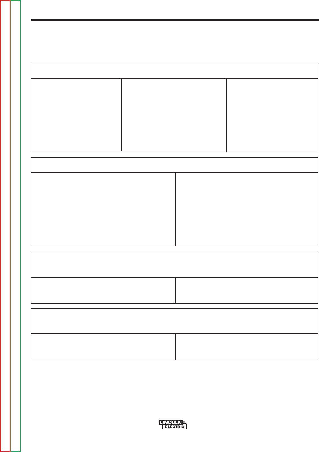
F-61F-61
PRECISION TIG 275
Return to Section TOC Return to Section TOC Return to Section TOC Return to Section TOC
Return to Master TOC Return to Master TOC Return to Master TOC Return to Master TOC
TROUBLESHOOTING & REPAIR
RETEST AFTER REPAIR
Should a machine under test be rejected for any reason requiring the removal of any
mechanical part that could effect the machineʼs electrical characteristics, or if any electrical
components are required or replaced, the machine must be retested.
INPUT IDLE AMPS
Input Volts/Hertz
208/60
230/60
460/60
575/60
Maximum Idle Amps
(without PFC)
6
5
3
2
Maximum Idle Amps
(without PFC)
36
32
16
13
OPEN CIRCUIT VOLTAGES
MAXIMUM AC OPEN CIRCUIT VOLTAGE
MAXIMUM DC OPEN CIRCUIT VOLTAGE
75 VAC
68 VDC
MAXIMUM ACCEPTABLE OUTPUT VOLTAGE
AT MINIMUM OUTPUT SETTINGS
DC TIG Mode 2 Amps @ 20 Volts
MAXIMUM ACCEPTABLE OUTPUT VOLTAGE
AT MAXIMUM OUTPUT SETTINGS
DC TIG Mode 300 Amps @ 32 Volts
RECOMMENDED METERS FOR MACHINE OUTPUT TESTS
VOLTMETER: AC and DC True RMS Meter - Fluke 8922A or equivalent
AMMETER: Columbia Type AX AC or DC Tong Ammeter
IMPORTANT: IF OTHER TYPE METERS ARE USED, RESULTS MAY NOT BE ACCURATE.


PRECISION TIG 275
Return to Master TOC Return to Master TOC Return to Master TOC Return to Master TOC
ELECTRICAL DIAGRAMS
G-1 G-1
Electrical Diagrams Section ..........................................................................................Section G
Wiring Diagram (Entire Machine) Code 10806 (G4031) .............................................................G-2
Wiring Diagram (Entire Machine) Code 10807 (G4031-1) ..........................................................G-3
Wiring Diagram (Entire Machine) Code 10893 (G4031-2) ..........................................................G-4
Wiring Diagram (Entire Machine) Code 11158 (G5692) ..............................................................G-5
Wiring Diagram (Entire Machine) Code 11159 (G5692-1)...........................................................G-6
Schematic (Entire Machine) Codes below 11000 (G4075) .........................................................G-7
Schematic (Entire Machine) Codes above 11000 (G5691) .........................................................G-8
Control P.C. Board Schematic Codes below 11000 (G3908 Page 1) ........................................G-9
Control P.C. Board Schematic Codes below 11000 (G3908 Page 2) .......................................G-10
Control P.C. Board Schematic Codes below 11000 (G3908 Page 3)........................................G-11
Control P.C. Board Assembly Codes below 11000(G3909-2) ...................................................G-12
Control P.C. Board Schematic Codes above 11000 (G4762 Page 1) ......................................G-13
Control P.C. Board Schematic Codes above 11000 (G4762 Page 2) ......................................G-14
Control P.C. Board Schematic Codes above 11000 (G4762 Page 3) ......................................G-15
Control P.C. Board Schematic Codes above 11000 (G4762 Page 4) ......................................G-16
Control P.C. Board Schematic Codes above 11000 (G4762 Page 5) ......................................G-17
Control P.C. Board Assembly Codes above 11000 (G4763-1)..................................................G-18
Protection P.C. Board Schematic (M16115) ..............................................................................G-19
Protection P.C. Board Assembly (M16062-1) ............................................................................G-20
ByPass / Stabilizer P.C. Board Schematic (S22530-1) (Code 10806 & 10807)........................G-21
ByPass / Stabilizer P.C. Board Assembly (L10121-1) (Code 10806 & 10807) .........................G-22
ByPass and CE P.C. Board Schematic (S24206) (Code 10893) ..............................................G-23
ByPass and CE P.C. Board Assembly (L10882-1) (Code 10893).............................................G-24
TIG Option P.C. Board Schematic Codes below 11000 (G4039 Page 1) .................................G-25
TIG Option P.C. Board Schematic Codes below 11000 (G4039 Page 2) .................................G-26
TIG Option P.C. Board Assembly Codes below 11000 (G4040-2) ............................................G-27
TIG Option P.C. Board Schematic Codes above 11000 (G4760 Page 1) .................................G-28
TIG Option P.C. Board Schematic Codes above 11000 (G4760 Page 2) .................................G-29
TIG Option P.C. Board Schematic Codes above 11000 (G4760 Page 3) .................................G-30
TIG Option P.C. Board Assembly Codes above 11000 (G4761-1)............................................G-31
TABLE OF CONTENTS
ELECTRICAL DIAGRAMS SECTION
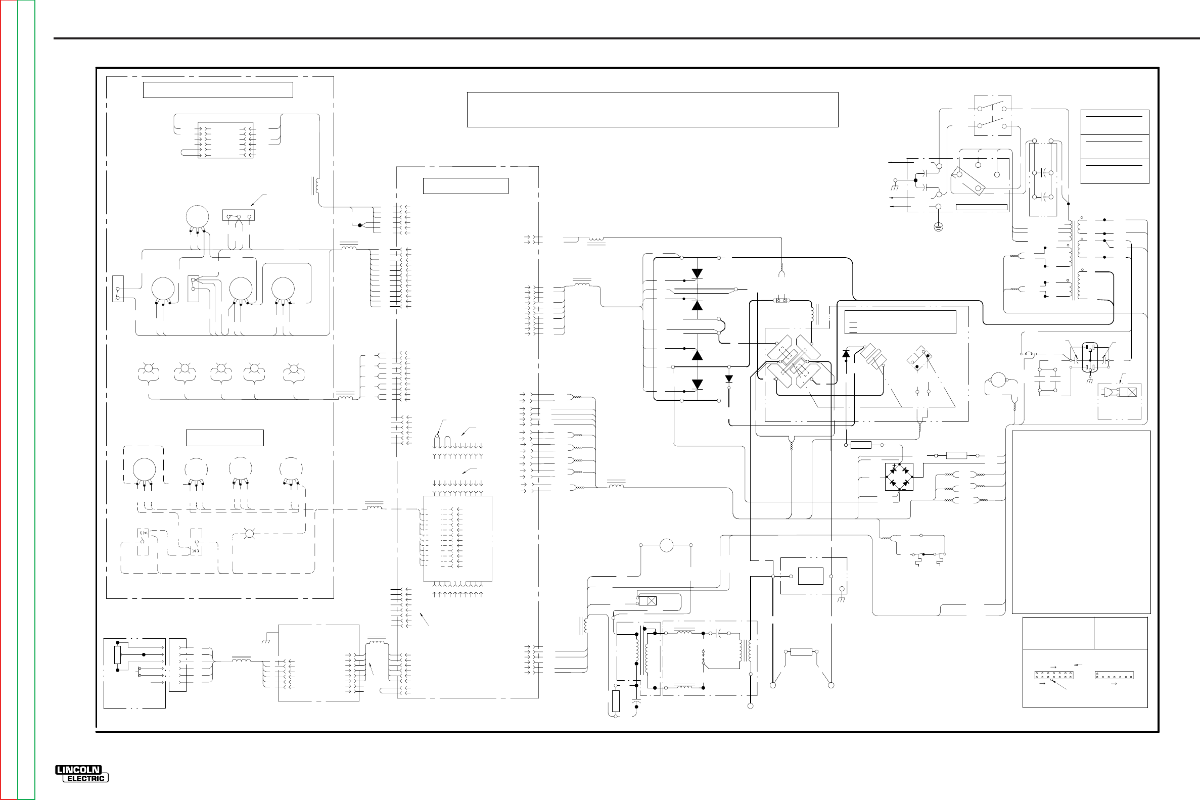
ELECTRICAL DIAGRAMS G-2
PRECISION TIG 275
®®
WIRING DIAGRAM - ENTIRE MACHINE - CODE 10806 (G4031)
RECEPTACLE
C
A
B B
CONTROL PC BOARD
10K A-B
F
E
D
C
AT MINIMUM
D
F
REMOTE
TM
AMPTROL
OPTIONAL
A
E
REMOTE
A
B
C
D
E
F
+-G
RGY
5
4
3
2
1
(STICK) (AUTO BAL) (REMOTE) (P. FLOW) (THERMAL)
8
4
1
2
3
6
56
BW
+-
BW
+-
BW
+-
BW
+
-
G
331
6
5
4
3
2
1
2
3
4
5
7
1
5
4
3
2
1
66
301
303
304B
306
302
METER
(VIEWED FROM REAR)
8
7
6
5
4
3
2
1
J23
J22
301
302
303
304
304A
306
304B
321
322
313
314
315
316
317
318
319
320
311
312
J8
J9
5
9
8
3
7
2
1
6
4
331
10
411
W
403
404
405
406
407
408
409
410
401
402
TIG OPTION PCB
(OPTIONAL)
8
7
6
5
4
3
2
1
220
G1
217
2
1W 221
R 222
11
3
10
2269
270
271
220B
6
5
4
3
2
1
233A
235
16
8
15
7
14
4
13
5
12
6
9
1
J11
L8
J10
J1
J5
J12
J4
J6
N.A.
8
6
2
3
4
5
7
1
J5A
N.B.
260
236
5
2
1
3
J7
PROTECTION PCB
R12
R11
R10
G
R9
FREQ ON TIME DOWN SLOPE
BACKGROUND
401D
402
403
405
406
408
409
410
401B
(PULSE ON)
+
-
ADVANCED CONTROL PANEL
(OPTIONAL)
401C
401D
W
B
VIEW OF CONNECTOR ON PC BOARD
ELECTRICAL SYMBOLS PER E1537.
OHMS/WATTS
COMPONENT VALUE
UNITS:
RESISTORS:
MFD/VOLTS
CAPACITORS:
8
LATCH
0F CONNECTOR J5
EXAMPLE: THIS IS PIN 7
32
LEAD COLORING CODE:
B-BLACK
21
8
G-GREEN
O-ORANGE
R-RED
CONNECTOR PIN NUMBERS:
7
14
U-BLUE
Y-YELLOW
W-WHITE
1
3
J5
460 VOLT CONNECTION
CONNECT STRAP TO
HIGH (H4) (AS SHOWN)
232
H4 (460V)
F
W209
18VAC
X7
R210
201
X8
F
S
X5
X2
X1
T1
78VAC
S
204
115VAC
X9
X10
20VAC
X3
H3 (230V)
H2 (208V)
X6
262
263
63.5VAC
267
268
CR4
231A
231
115VAC
X4
CB1
15A
232
231
F
S
F
S
F
S
CR4
233B
234
48
26
233
01
233A
C8 C9
214
213
R8 267
233A
231A
268
269
220B
271
270
220A
262
263
201
204
W209
R210
115VAC
ARC STARTER AS'BLY
R5
SV1
GAS VALVE
L3
C6
T2
C7
T3
GAP
SPARK
L2
237
S
F
R6
BYPASS/
STABILIZER
PC BOARD
FAN
260
235
233A
239 238
284 285
236B
236
231D
231E
231A
231E
233A
POS
D
FRONT GANG
NEG
POLARITY SWITCH MICRO SWITCH
POLARITY
S2
NO
(REAR VIEW, SHOWN
X2
NC
MICRO-SWITCH
CLOSED
CLOSED
OPEN
TO GROUND PER
C
A-C, D-E, B-F
B-D, C-E, A-F, G-H
G
DC+
REAR GANG
DC-
266A
S2A
265A
H
A
L1 AC
SWITCH
E
F
ELECTRICAL CODE
NATIONAL
253
POS
B-D, A-E, C-F, G-H
IN AC POSITION)
D2
B
252
R7
286
W221
R222
271A BACKGROUND
RECTIFIER
265
266
G4
G3
G2
213
214
201
204
W209
R210
262
263
265
266
252
253
G1
G2
217
216
220
G3
220A
G4
218
SCR4 D1
X1
NEG
SCR3
POS
(+)
SCR1
SCR2
252
(-)
B
G4031
B
PRECISION TIG 275 WIRING DIAGRAM
L9
L10
L7
L6
L5
L12
L4
L13
L11
J3
N.D.
N.C.
L1 (U)
L2 (V)
C1
RECONNECT PANEL
H4 H2
H1
H3
250
S1
POWER SWITCH
H1
C5
C4
CAPACITORS
(OPTIONAL)
POWER FACTOR
C2
A
GROUND
HIGH
MID
LOW
COM
251
21 3456 89
10
7
21 3456 89
10
7
J2
J3
21 3456 89
10
7
OR N.C.
230 VOLT CONNECTION
CONNECT STRAP TO
MID (H3)
208 VOLT CONNECTION
CONNECT STRAP TO
LOW (H2)
407
L1 (U)
L2 (V)
FRONT
ELECTRODE
REAR
ELECTRODE
WORK
TRANSFORMER
PRIMARY
THERMOSTAT TRANSFORMER
SECONDARY
THERMOSTAT
PULSE
2-STEP
401
404
ON
OFF
411
401A
4-STEP
TRIGGER
401B
R4
R1R2
BALANCE
MINIMUM
OUTPUT
MAXIMUM
OUTPUT
MODE
REMOTE
R3
POST FLOW
319
322
316C
313C
316B
315
316
317
311
312
313
318
313B
TIG
STICK
321
DISPLAY
314
320
LOCAL
311A
316A
316C
311A
316A316B
F
C
S
E
N.E.
CONTROL PANEL (VIEWED FROM REAR)
332
333
BW
334
335
B
W
332 B
W
333 B
W
334 B
W
335 B
W
12
11
10
9
8
6
5
4
3
1
2
7
12
11
10
9
8
6
5
4
3
1
2
7
6
4
10
9
216
218
C1,C2 POWER FACTOR CAPACITORS, 50/460 (OPTIONAL)
C4,C5 BY-PASS CAPACITORS, .0047
C6 HIGH VOLTAGE CAPACITOR, .0015/12kV
C7 PHASE SHIFT CAPACITOR, 15uF/250VAC
C8,C9 HIGH FREQ PROTECTION CAPACITORS, .22/400
CB1 CIRCUIT BREAKER, 15 AMP
CR4 12V DC RELAY COIL
D1 FREE WHEELING DIODE
D2 BACKGROUND DIODE
L1 OUTPUT INDUCTOR (CHOKE)
L2,L3 HIGH FREQ INDUCTORS
L4 -L13 RF TOROID CHOKES
R1 OUTPUT CONTROL POTENTIOMETER, 10K
R2 BALANCE CONTROL POTENTIOMETER, 10K
R3 POST FLOW POTENTIOMETER, 10K
R4 MIN OUTPUT POTENTIOMETER, 10K
R5 PHASE SHIFT RESISTOR, 200/100
R6 HOLDING RESISTOR, 50/225
R7 RESISTOR, 20/100
R8 RESISTOR, 5/50
R9 FREQ CONTROL POTENTIOMETER, 10K
R10 ON TIME CONTROL POTENTIOMETER, 10K
R11 BACKGROUND POTENTIOMETER, 10K
R12 DOWN SLOPE POTENTIOMETER, 10K
S1 INPUT POWER SWITCH
S2 POLARITY SWITCH
S2A MICROSWITCH ON POLARITY SWITCH
SCR1,2,3,4 MAIN POWER SCR'S
SV1 GAS SOLENOID VALVE, 115VAC
SV2 WATER SOLENOID VALVE, 115VAC (OPTIONAL)
T1 MAIN TRANSFORMER
T2 HIGH VOLTAGE TRANSFORMER
T3 HIGH FREQ TRANSFORMER
N.A. CONNECTION IS PIN TO PIN BETWEEN J23 AND J5.
N.B. ROBOTIC INTERFACE CONNECTION.
N.C. REMOVE JUMPER PLUG IN J3 WHEN INSTALLING
TIG OPTION PC BOARD.
N.D. DISCONNECT JUMPER LEAD BETWEEN PIN 1 AND
PIN 2 IN J3 TO DOUBLE PREFLOW & POSTFLOW TIMES.
N.E. DISPLAY TOGGLE SHOWN IN MIN AMP POSITION.
N.F. PLUGS INTO LOWER SWITCHED RECEPTACLE.
SV2
WATER VALVE
(OPTIONAL)
N.F.
313A
G-2
NOTE: This diagram is for reference only. It may not be accurate for all machines covered by this manual. The wiring diagram specific to your code is pasted inside one of the enclosure panels of your machine.
Return to Section TOC Return to Section TOC Return to Section TOC Return to Section TOC
Return to Master TOC Return to Master TOC Return to Master TOC Return to Master TOC
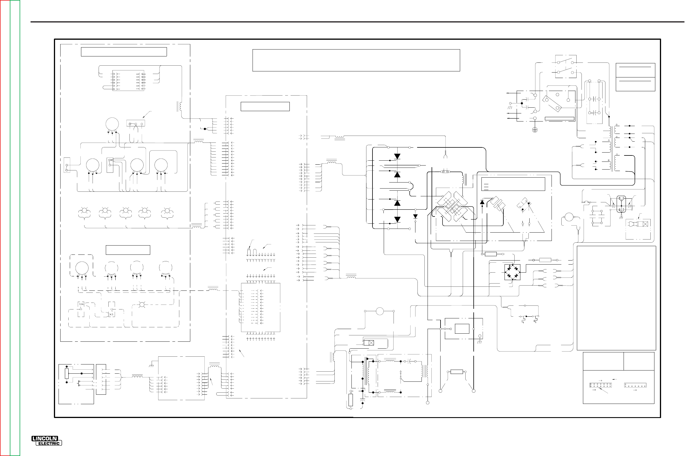
ELECTRICAL DIAGRAMS G-3
PRECISION TIG 275
®®
WIRING DIAGRAM - ENTIRE MACHINE - CODE 10807 (G4031-1)
RECEPTACLE
C
A
B B
CONTROL PC BOARD
10K A-B
F
E
D
C
AT MINIMUM
D
F
REMOTE
TM
AMPTROL
OPTIONAL
A
E
REMOTE
A
B
C
D
E
F
+-G
RGY
5
4
3
2
1
(STICK) (AUTO BAL) (REMOTE) (P. FLOW) (THERMAL)
8
4
1
2
3
6
56
BW
+-
BW
+-
BW
+-
BW
+
-
G
331
6
5
4
3
2
1
2
3
4
5
7
1
5
4
3
2
1
66
301
303
304B
306
302
METER
(VIEWED FROM REAR)
8
7
6
5
4
3
2
1
J23
J22
301
302
303
304
304A
306
304B
321
322
313
314
315
316
317
318
319
320
311
312
J8
J9
5
9
8
3
7
2
1
6
4
331
10
411
W
403
404
405
406
407
408
409
410
401
402
TIG OPTION PCB
(OPTIONAL)
8
7
6
5
4
3
2
1
220
G1
217
2
1W 221
R 222
11
3
10
2269
270
271
220B
6
5
4
3
2
1
233A
235
16
8
15
7
14
4
13
5
12
6
9
1
J11
L8
J10
J1
J5
J12
J4
J6
N.A.
8
6
2
3
4
5
7
1
J5A
N.B.
260
236
5
2
1
3
J7
PROTECTION PCB
R12
R11
R10
R9
FREQ ON TIME DOWN SLOPE
BACKGROUND
401D
402
403
405
406
408
409
410
401B
ADVANCED CONTROL PANEL
(OPTIONAL)
401C
401D
VIEW OF CONNECTOR ON PC BOARD
ELECTRICAL SYMBOLS PER E1537.
OHMS/WATTS
COMPONENT VALUE
UNITS:
RESISTORS:
MFD/VOLTS
CAPACITORS:
8
LATCH
0F CONNECTOR J5
EXAMPLE: THIS IS PIN 7
32
LEAD COLORING CODE:
B-BLACK
21
8
G-GREEN
O-ORANGE
R-RED
CONNECTOR PIN NUMBERS:
7
14
U-BLUE
Y-YELLOW
W-WHITE
1
3
J5
575 VOLT CONNECTION
CONNECT STRAP TO
HIGH (H4) (AS SHOWN)
232
H4 (575V)
F
W209
18VAC
X7
R210
201
X8
F
S
X5
X2
X1
T1
78VAC
S
204
115VAC
X9
X10
20VAC
X3
H2 (460V)
X6
262
263
63.5VAC
267
268
CR4
231A
231
115VAC
X4
CB1
15A
232
231
F
S
F
S
F
S
CR4
233B
234
48
26
233
01
233A
C8 C9
214
213
R8 267
233A
231A
268
269
220B
271
270
220A
262
263
201
204
W209
R210
115VAC
ARC STARTER AS'BLY
R5
SV1
GAS VALVE
L3
C6
T2
C7
T3
GAP
SPARK
L2
237
S
F
R6
BYPASS/
STABILIZER
PC BOARD
FAN
260
235
233A
239 238
284 285
236B
236
231D
231E
231A
231E
233A
POS
D
FRONT GANG
NEG
POLARITY SWITCH MICRO SWITCH
POLARITY
S2
NO
(REAR VIEW, SHOWN
X2
NC
MICRO-SWITCH
CLOSED
CLOSED
OPEN
TO GROUND PER
C
A-C, D-E, B-F
B-D, C-E, A-F, G-H
G
DC+
REAR GANG
DC-
266A
S2A
265A
H
A
L1 AC
SWITCH
E
F
ELECTRICAL CODE
NATIONAL
253
POS
B-D, A-E, C-F, G-H
IN AC POSITION)
D2
B
252
R7
286
W221
R222
271A BACKGROUND
RECTIFIER
265
266
G4
G3
G2
213
214
201
204
W209
R210
262
263
265
266
252
253
G1
G2
217
216
220
G3
220A
G4
218
SCR4 D1
X1
NEG
SCR3
POS
(+)
SCR1
SCR2
252
(-)
B
G4031-1
B
PRECISION TIG 275 WIRING DIAGRAM
L9
L10
L7
L6
L5
L12
L4
L13
L11
J3
N.D.
N.C.
L1 (U)
L2 (V)
C1
RECONNECT PANEL
H4 H2
H1
250
S1
POWER SWITCH
H1
C5
C4
CAPACITORS
(OPTIONAL)
POWER FACTOR
C2
A
GROUND
HIGH
MID
LOW
COM
251
21 3456 89
10
7
21 3456 89
10
7
J2
J3
21 3456 89
10
7
OR N.C.
460 VOLT CONNECTION
CONNECT STRAP TO
LOW (H2)
407
L1 (U)
L2 (V)
FRONT
ELECTRODE
REAR
ELECTRODE
WORK
TRANSFORMER
PRIMARY
THERMOSTAT TRANSFORMER
SECONDARY
THERMOSTAT
PULSE
2-STEP
401
404
ON
OFF
411
401A
4-STEP
TRIGGER
401B
R4
R1R2
BALANCE
MINIMUM
OUTPUT
MAXIMUM
OUTPUT
MODE
REMOTE
R3
POST FLOW
319
322
316C
313C
316B
315
316
317
311
312
313
318
313B
TIG
STICK
321
DISPLAY
314
320
LOCAL
311A
316A
316C
311A
316A316B
F
C
S
E
N.E.
CONTROL PANEL (VIEWED FROM REAR)
332
333
BW
334
335
B
W
332 B
W
333 B
W
334 B
W
335 B
W
12
11
10
9
8
6
5
4
3
1
2
7
12
11
10
9
8
6
5
4
3
1
2
7
6
4
10
9
216
218
C1,C2 POWER FACTOR CAPACITORS, 50/460 (OPTIONAL)
C4,C5 BY-PASS CAPACITORS, .0047
C6 HIGH VOLTAGE CAPACITOR, .0015/12kV
C7 PHASE SHIFT CAPACITOR, 15uF/250VAC
C8,C9 HIGH FREQ PROTECTION CAPACITORS, .22/400
CB1 CIRCUIT BREAKER, 15 AMP
CR4 12V DC RELAY COIL
D1 FREE WHEELING DIODE
D2 BACKGROUND DIODE
L1 OUTPUT INDUCTOR (CHOKE)
L2,L3 HIGH FREQ INDUCTORS
L4 -L13 RF TOROID CHOKES
R1 OUTPUT CONTROL POTENTIOMETER, 10K
R2 BALANCE CONTROL POTENTIOMETER, 10K
R3 POST FLOW POTENTIOMETER, 10K
R4 MIN OUTPUT POTENTIOMETER, 10K
R5 PHASE SHIFT RESISTOR, 200/100
R6 HOLDING RESISTOR, 50/225
R7 RESISTOR, 20/100
R8 RESISTOR, 5/50
R9 FREQ CONTROL POTENTIOMETER, 10K
R10 ON TIME CONTROL POTENTIOMETER, 10K
R11 BACKGROUND POTENTIOMETER, 10K
R12 DOWN SLOPE POTENTIOMETER, 10K
S1 INPUT POWER SWITCH
S2 POLARITY SWITCH
S2A MICROSWITCH ON POLARITY SWITCH
SCR1,2,3,4 MAIN POWER SCR'S
SV1 GAS SOLENOID VALVE, 115VAC
SV2 WATER SOLENOID VALVE, 115VAC (OPTIONAL)
T1 MAIN TRANSFORMER
T2 HIGH VOLTAGE TRANSFORMER
T3 HIGH FREQ TRANSFORMER
N.A. CONNECTION IS PIN TO PIN BETWEEN J23 AND J5.
N.B. ROBOTIC INTERFACE CONNECTION.
N.C. REMOVE JUMPER PLUG IN J3 WHEN INSTALLING
TIG OPTION PC BOARD.
N.D. DISCONNECT JUMPER LEAD BETWEEN PIN 1 AND
PIN 2 IN J3 TO DOUBLE PREFLOW & POSTFLOW TIMES.
N.E. DISPLAY TOGGLE SHOWN IN MIN AMP POSITION.
N.F. PLUGS INTO LOWER SWITCHED RECEPTACLE.
SV2
WATER VALVE
(OPTIONAL)
N.F.
G
(PULSE ON)
+
-
W
B
313A
G-3
NOTE: This diagram is for reference only. It may not be accurate for all machines covered by this manual. The wiring diagram specific to your code is pasted inside one of the enclosure panels of your machine.
Return to Section TOC Return to Section TOC Return to Section TOC Return to Section TOC
Return to Master TOC Return to Master TOC Return to Master TOC Return to Master TOC
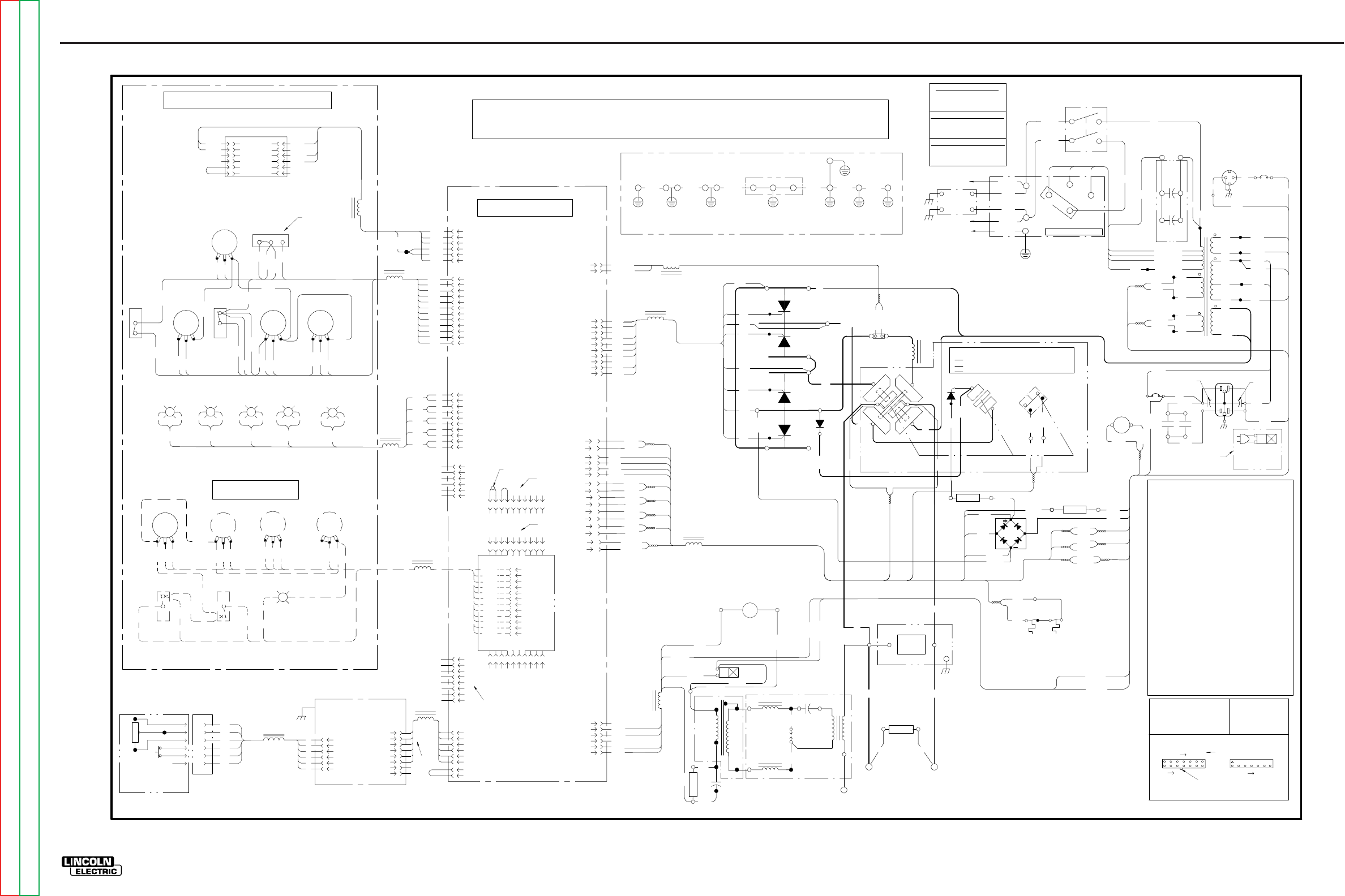
ELECTRICAL DIAGRAMS G-4
PRECISION TIG 275
®®
WIRING DIAGRAM - ENTIRE MACHINE - CODE 10893 (G4031-2)
RECEPTACLE
C
A
B B
CONTROL PC BOARD
10K A-B
F
E
D
C
AT MINIMUM
D
F
REMOTE
TM
AMPTROL
OPTIONAL
A
E
REMOTE
A
B
C
D
E
F
+-G
RGY
5
4
3
2
1
(STICK) (AUTO BAL) (REMOTE) (P. FLOW) (THERMAL)
8
4
1
2
3
6
56
BW
+-
BW
+-
BW
+-
BW
+
-
G
331
6
5
4
3
2
1
2
3
4
5
7
1
5
4
3
2
1
66
301
303
304B
306
302
METER
(VIEWED FROM REAR)
8
7
6
5
4
3
2
1
J23
J22
301
302
303
304
304A
306
304B
321
322
313
314
315
316
317
318
319
320
311
312
J8
J9
5
9
8
3
7
2
1
6
4
331
10
411
W
403
404
405
406
407
408
409
410
401
402
TIG OPTION PCB
(OPTIONAL)
8
7
6
5
4
3
2
1
220
G1
217
2
1W 221
R 222
11
3
10
2269
270
271
220B
6
5
4
3
2
1
233A
235
16
8
15
7
14
4
13
5
12
6
9
1
J11
L8
J10
J1
J5
J12
J4
J6
N.A.
8
6
2
3
4
5
7
1
J5A
N.B.
260
236
5
2
1
3
J7
PROTECTION PCB
R12
R11
R10
R9
FREQ ON TIME DOWN SLOPE
BACKGROUND
401D
402
403
405
406
408
409
410
401B
ADVANCED CONTROL PANEL
(OPTIONAL)
401C
401D
VIEW OF CONNECTOR ON PC BOARD
ELECTRICAL SYMBOLS PER E1537.
OHMS/WATTS
COMPONENT VALUE
UNITS:
RESISTORS:
MFD/VOLTS
CAPACITORS:
8
LATCH
0F CONNECTOR J5
EXAMPLE: THIS IS PIN 7
32
LEAD COLORING CODE:
B-BLACK
21
8
G-GREEN
O-ORANGE
R-RED
CONNECTOR PIN NUMBERS:
7
14
U-BLUE
Y-YELLOW
W-WHITE
1
3
J5
415 VOLT CONNECTION
CONNECT STRAP TO
HIGH (H4) (AS SHOWN)
232
H5 (440V)
F
W209
18VAC
X7
R210
201
X8
F
S
X5
X2
X1
T1
78VAC
S
204
115VAC
X9
X10
20VAC
X3
H4 (415V)
H2 (220V)
X6
262
263
63.5VAC
267
268
CR4
231A
231
115VAC
X4
CB1
15A
232
231
S
F
S
F
S
CR4
233B
234
48
26
233
01
233A
C8 C9
214
213
R8 267
233A
231A
268
269
220B
271
270
220A
262
263
201
204
W209
R210
115VAC
ARC STARTER AS'BLY
R5
SV1
GAS VALVE
L3
C6
T2
C7
T3
GAP
SPARK
L2
237
S
F
R6
BYPASS/
STABILIZER
PC BOARD
FAN
260
235
233A
239 238
284 285
236B
236
231D
231E
231A
231E
233A
POS
D
FRONT GANG
NEG
POLARITY SWITCH MICRO SWITCH
POLARITY
S2
NO
(REAR VIEW, SHOWN
X2
NC
MICRO-SWITCH
CLOSED
CLOSED
OPEN
TO GROUND PER
C
A-C, D-E, B-F
B-D, C-E, A-F, G-H
G
DC+
REAR GANG
DC-
266A
S2A
265A
H
A
L1 AC
SWITCH
E
F
ELECTRICAL CODE
NATIONAL
253
POS
B-D, A-E, C-F, G-H
IN AC POSITION)
D2
B
252
R7
286
W221
R222
271A BACKGROUND
RECTIFIER
265
266
G4
G3
G2
213
214
201
204
W209
R210
262
263
265
266
252
253
G1
G2
217
216
220
G3
220A
G4
218
SCR4 D1
X1
NEG
SCR3
POS
(+)
SCR1
SCR2
252
(-)
B
G4031-2
B
N.A. CONNECTION IS PIN TO PIN BETWEEN J23 AND J5.
N.B. ROBOTIC INTERFACE CONNECTION.
N.C. REMOVE JUMPER PLUG IN J3 WHEN INSTALLING
TIG OPTION PC BOARD.
N.D. DISCONNECT JUMPER LEAD BETWEEN PIN 1 AND
PIN 2 IN J3 TO DOUBLE PREFLOW & POSTFLOW TIMES.
N.E. DISPLAY TOGGLE SHOWN IN MIN AMP POSITION.
N.F. PLUGS INTO LOWER SWITCHED RECEPTACLE.
PRECISION TIG 275 WIRING DIAGRAM
L9
L10
L7
L6
L5
L12
L4
L13
L11
J3
N.D.
N.C.
C1
RECONNECT PANEL
H4 H2
H1
H3
S1
POWER SWITCH
H1
CAPACITORS
(OPTIONAL)
POWER FACTOR
C2
GROUND
HIGH
MID
LOW
COM
251
21 3456 89
10
7
21 3456 89
10
7
J2
J3
21 3456 89
10
7
OR N.C.
380-400 VOLT CONNECTION
CONNECT STRAP TO
MID (H3)
220-230 VOLT CONNECTION
CONNECT STRAP TO
LOW (H2)
407
L1 (U)
L2 (V)
FRONT
ELECTRODE
REAR
ELECTRODE
WORK
TRANSFORMER
PRIMARY
THERMOSTAT TRANSFORMER
SECONDARY
THERMOSTAT
PULSE
2-STEP
401
404
ON
OFF
411
401A
4-STEP
TRIGGER
401B
R4
R1R2
BALANCE
MINIMUM
OUTPUT
MAXIMUM
OUTPUT
MODE
REMOTE
R3
POST FLOW
319
322
316C
313C
316B
315
316
317
311
312
313
318
313B
TIG
STICK
321
DISPLAY
314
320
LOCAL
311A
316A
316C
311A
316A316B
F
C
S
E
N.E.
CONTROL PANEL (VIEWED FROM REAR)
332
333
BW
334
335
B
W
332 B
W
333 B
W
334 B
W
335 B
W
12
11
10
9
8
6
5
4
3
1
2
7
12
11
10
9
8
6
5
4
3
1
2
7
6
4
10
9
216
218
SV2
WATER VALVE
(OPTIONAL)
105VAC
50A
F
X14
52
CB1
15A
52
CB2
5A
51
50
50A
C1,C2 POWER FACTOR CAPACITORS, 50/460 (OPTIONAL)
C4,C5 BY-PASS CAPACITORS, .0047
C6 HIGH VOLTAGE CAPACITOR, .0015/12kV
C7 PHASE SHIFT CAPACITOR, 15uF/250VAC
C8,C9 HIGH FREQ PROTECTION CAPACITORS, .22/400
CB1 CIRCUIT BREAKER, 15 AMP
CB2 CIRCUIT BREAKER, 5 AMP
CR4 12V DC RELAY COIL
D1 FREE W HEELING DIODE
D2 BACKGROUND DIODE
L1 OUTPUT INDUCTOR (CHOKE)
L2,L3 HIGH FREQ INDUCTORS
L4 -L13 RF TOROID CHOKES
R1 OUTPUT CONTROL POTENTIOMETER, 10K
R2 BALANCE CONTROL POTENTIOMETER, 10K
R3 POST FLOW POTENTIOMETER, 10K
R4 MIN OUTPUT POTENTIOMETER, 10K
R5 PHASE SHIFT RESISTOR, 200/100
R6 HOLDING RESISTOR, 50/225
R7 RESISTOR, 20/100
R8 RESISTOR, 5/50
R9 FREQ CONTROL POTENTIOMETER, 10K
R10 ON TIME CONTROL POTENTIOMETER, 10K
R11 BACKGROUND POTENTIOMETER, 10K
R12 DOWN SLOPE POTENTIOMETER, 10K
S1 INPUT POWER SWITCH
S2 POLARITY SWITCH
S2A MICROSW ITCH ON POLARITY SWITCH
SCR1,2,3,4 MAIN POW ER SCR'S
SV1 GAS SOLENOID VALVE, 115VAC
SV2 WATER SOLENOID VALVE, 115VAC (OPTIONAL)
T1 MAIN TRANSFORMER
T2 HIGH VOLTAGE TRANSFORMER
T3 HIGH FREQ TRANSFORMER
220VAC
N.F.
H3 (380V)
250
A
250
G
(PULSE ON)
+
-
W
B
L1 (U)
L2 (V)
L1A
L2A
BYPASS
PC BOARD
TO GROUND PER
NATIONAL
ELECTRIC CODE
GND-H2
GND-H GND4 GND5
GND1
RECONNECT PANEL SUPPORT
T1
TRANS.
FOOT
CASE
BACK
CASE
FRONT
CONTROL
PANEL
115 VAC
RECEPT.
GAS
VALVE
GND6
PROTECTIVE BONDING CIRCUIT 220 VAC
RECEPT.
313A
G-4
NOTE: This diagram is for reference only. It may not be accurate for all machines covered by this manual. The wiring diagram specific to your code is pasted inside one of the enclosure panels of your machine.
Return to Section TOC Return to Section TOC Return to Section TOC Return to Section TOC
Return to Master TOC Return to Master TOC Return to Master TOC Return to Master TOC
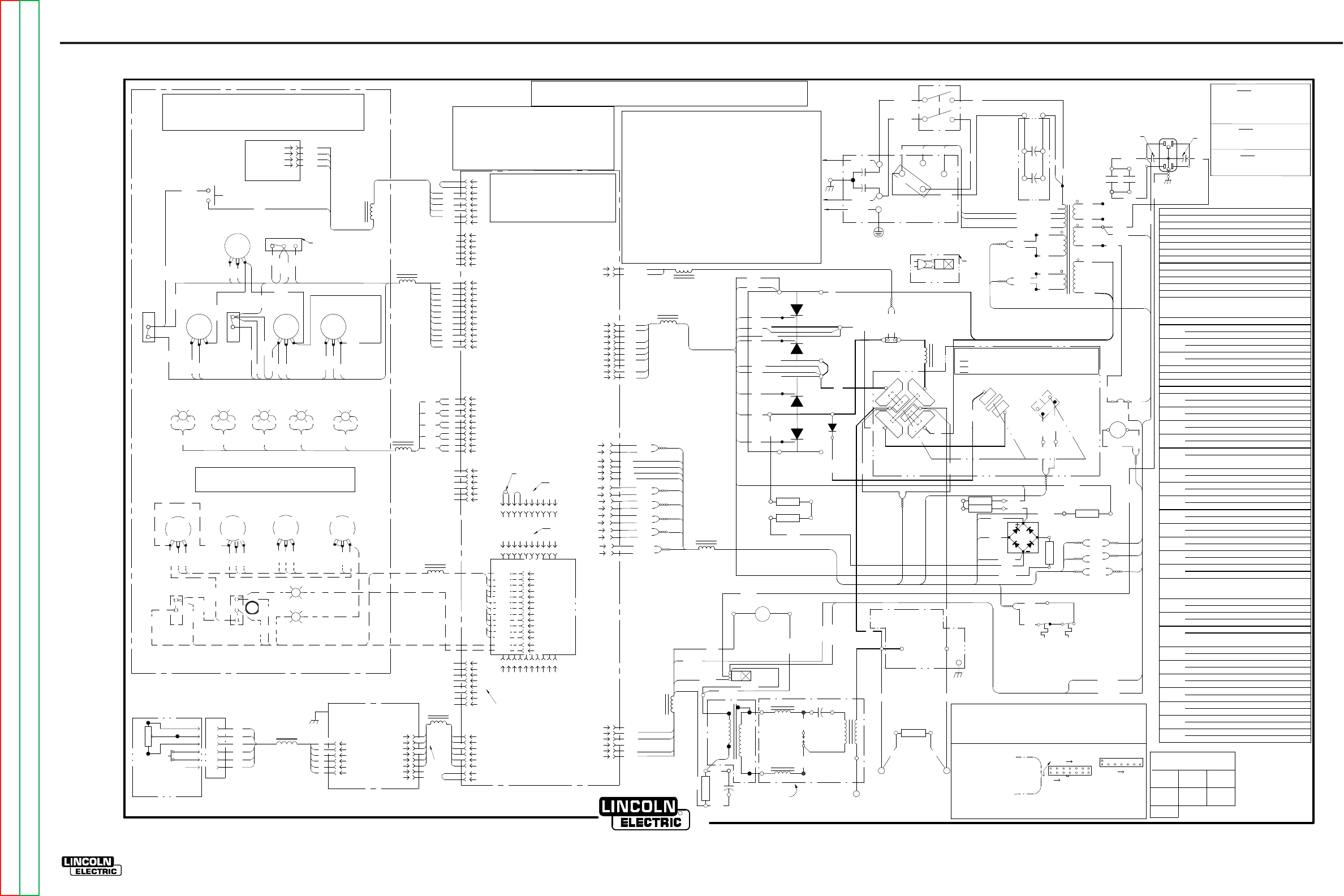
ELECTRICAL DIAGRAMS G-5
PRECISION TIG 275
®®
WIRING DIAGRAM - ENTIRE MACHINE - CODE 11158 (G5692)
RECEPTACLE
C
A
B B
10K A-B
F
E
D
C
MINIMUM
D
F
TM
AMPTROL
A
E
REMOTE
A
B
C
D
E
F
+-G
RGY
8
4
1
2
3
6
56
BW
+-
BW
+-
BW
+-
BW
+
-
G
331
6
5
4
3
2
1
2
3
4
5
7
1
344
345
343
8
7
6
5
4
3
2
1
J23
J22
321
322
313
314
315
316
317
318
319
320
311
312
J8
J9
5
9
8
3
7
2
1
6
4
331
10
411
W
403
404
405
406
407
408
409
410
401
402
8
7
6
5
4
3
2
1
220
G1
217
2
1W 221
R 222
11
3
10
2269
270
271
229A
6
5
4
3
2
1
233A
235
16
8
15
7
14
4
13
5
12
6
9
1
J11
L8
J10
J1
J5
J12
J4
J6
N.A.
8
6
2
3
4
5
7
1
J5A
N.B.
260
236
5
2
1
3
J7
G
FREQ
401D
402
403
405
406
408
409
410
401B
+
-
401C
401D
W
B
232
H4 (460V)
F
W209
18VAC
X7
R210
201
X8
F
S
X5
X2
X1
T1
78VAC
S
204
115VAC
X9
X10
20VAC
X3
H3 (230V)
H2 (208V)
X6
262
263
63.5VAC
CR4
231A
231
115VAC
X4
CB1
15A
232
231
F
S
F
S
F
S
CR4
233B
234
48
26
233
01
233A
C8 C9
214
213
R8A
268
233A
231A
217A
269
229A
271
270
229
262
263
201
204
W209
R210
115VAC
R5
SV1
L3
C6
T2
C7
T3
GAP
SPARK
L2
237
S
F
R6
FAN
260
235
233A
239 238
284 285
236B
236
231D
231E
231A
231E
233A
POS
D
NEG
S2
NO
X2
NC
TO GROUND PER
C
A-C, D-E, B-F
B-D, C-E, A-F, G-H
G
DC+
DC-
266A
S2A
265A
H
A
L1 AC
E
F
ELECTRICAL CODE
NATIONAL
253
POS
B-D, A-E, C-F, G-H
B
252
R7C
218B
W221
R222
265
266
G4
G3
G2
213
214
201
204
W209
R210
262
263
265
266
252
253
G1
G2
217
216
220
G3
220A
G4
SCR4 D1
X1
NEG
SCR3
POS
(+)
SCR1
SCR2
252
(-)
B
R
CLEVELAND , OHIO
G5692PRINT
A
L9
L10
L7
L6
L5
L12
L4
L13
L11
J3
N.D.
N.C.
L1 (U)
L2 (V)
C1
H4 H2
H1
H3
250
S1
H1
C5
C4
C2
A
HIGH
MID
LOW
COM
251
21 3456 89
10
7
21 3456 89
10
7
J2
J3
21 3456 89
10
7
OR N.C.
407
L1 (U)
L2 (V)
401
404
411
401A
401B
319
322
313C
316B
315
316
317
311
312
313
318
313B
321
314
320
311A
316A
316C
311A
316A316B
F
C
S
E
N.E.
332
333
BW
334
335
B
W
332 B
W
333 B
W
334 B
W
335 B
W
12
11
10
9
8
6
5
4
3
1
2
7
12
11
10
9
8
6
5
4
3
1
2
7
6
4
10
9
216
218
N.A. CONNEXION CONTACT-CONTACT ENTRE J23 ET J5
N.B. CONNEXION INTERFACE ROBOTIQUE
N.C. ENLEVER LA FICHE CAVALIER EN J3 QUAND ON INSTALLE LE CI EN
OPTION TIG
N.D. DÉCONNECTER LE CÂBLE DU CAVALIER ENTRE LES CONTACTS 1 ET
2 DANS J3 POUR DOUBLER TEMPS DE PRÉGAZ ET POSTGAZ.
N.E. AFFICHE LA BASCULE ILLUSTRÉE EN POSITION A MINIMUM.
N.F. SE BRANCHE LA PRISE À INTERRUPTEUR INFÉRIEURE.
N.A. LA CONEXIÓN ES DE PIN A PIN ENTRE J23 Y J5.
N.B. CONEXIÓN DE LA INTERFAZ ROBÓTICA.
N.C. REMUEVA EL CONECTOR DE PUENTE EN J3 CUANDO INSTALE LA
TARJETA DE PC TIG OPCIONAL.
N.D. DESCONECTE EL CABLE DEL PUENTE ENTRE EL PIN 1 Y PIN 2 EN J3
PARA DUPLICAR LOS TIEMPOS DE PRE Y POSTFLUJO.
N.E. EL INTERRUPTOR DE PALANCA DE LA PANTALLA SE MUESTRA EN LA
POSICIÓN MÍNIMA DE AMPERIOS.
N.F. ENCHUFES EN RECEPTÁCULO CONMUTADO INFERIOR.
SV2
N.F.
313A
R7D 271A
R8B
216A
218A
216A
R7A
230
R7B
218
217A
218A
GND6
GND6
413
W 2
1J20
R
+-
BW
413
4
3
2
1347
8
6
2
3
4
5
7
1
J13
343
344
345
346
347
J7
316D
316D
346
S3
229
316C
233
N.A. CONNECTION IS PIN TO PIN BETWEEN J23 AND J5.
N.B. ROBOTIC INTERFACE CONNECTION.
N.C. REMOVE JUMPER PLUG IN J3 WHEN INSTALLING
TIG OPTION PC BOARD.
N.D. DISCONNECT JUMPER LEAD BETWEEN PIN 1 AND
PIN 2 IN J3 TO DOUBLE PREFLOW & POSTFLOW TIMES.
N.E. DISPLAY TOGGLE SHOWN IN MIN AMP POSITION.
N.F. PLUGS INTO LOWER SWITCHED RECEPTACLE.
VIEW OF CONNECTOR ON PC BOARD
ELECTRICAL SYMBOLS PER E1537.
SYMBOLES ÉLECTRIQUES SELON E1537
SÍMBOLOS ELÉCTRICOS CONFORME A E1537
COMPONENT VALUE UNITS:
RESISTORS: OHMS/WATTS
CAPACITORS: MFD/VOLTS
8
0F CONNECTOR J5
EXAMPLE: THIS IS PIN 1
32
LEAD COLORING CODE:
CODE DE COULEUR DES CÂBLES:
CÓDIGO DE COLORES DE CABLES:
B-BLACK
NOIR
NEGRO
21
8
O-ORANGE
NARANJA
CONNECTOR PIN NUMBERS: NOMBRE DE CONTACTS CONNECTEURS
NÚMEROS DE PINES DE CONECTORES:
7
14
1
3
J5
UNITÉS DE VALEUR DES COMPOSANTS:
RÉSISTANCES: OHMS/WATTS
CONDENSATEURS: MFD/VOLTS
EXEMPLE: C'EST LE CONTACT 1
DU CONNECTEUR J5
EJEMPLO: ESTE ES EL PIN 1 DEL
CONECTOR J5 VUE DES CONNECTEURS SUR CI
VISTA DEL CONECTOR EN LA
TARJETA ELECTRONICA
460 V
CONNECT STRAP TO HIGH (H4) (AS SHOWN)
CONNECTER LA BRIDE SUR HAUT (H4)
(COMME ILLUSTRÉ)
SUJETADOR DE CONEXIÓN A ALTO (H4)
(COMO SE MUESTRA)
230 V
CONNECT STRAP TO MID (H3)
CONNECTER LA BRIDE SUR MOYEN (H3)
SUJETADOR DE CONEXIÓN A MEDIO (H3)
208 V
CONNECT STRAP TO LOW (H2)
CONNECTER LA BRIDE SUR BAS (H2)
SUJETADOR DE CONEXIÓN A BAJO(H2)
PRECISION TIG 275 WIRING DIAGRAM
SCHÉMA DE CÂBLAGE DIAGRAMAS DE CABLEADO
CONTROL PANEL (VIEWED FROM REAR)
PANNEAU DE COMMANDE (VIEWED FROM REAR)
PANEL DE CONTROL (VISTO DESDE ATRÁS)
METER
COMPTEUR
MEDIDOR
DISPLAY
AFFICHAGE
PANTALLA
ADVANCED CONTROL PANEL (OPTIONAL)
PANNEAU DE COMMANDE AVANCÉ (OPTION)
PANEL DE CONTROL AVANZADO (OPCIONAL)
BACKGROUND
ARRIÈRE PLAN
FONDO
PRISE À DISTANCE
RECEPTÁCULO REMOTO
PROTECTION PCB
CI PROTECTION
PCB DE PROTECCIÓN
TIG OPTION PCB
CI OPTION TIG
PCB DE OPCIÓN
TIG
CONTROL PC BOARD
CI DE COMMANDE
TABLEAU DE
TARJETA ELECTRONICA
DE CONTROL
VENTILATEUR
VENTILADOR
ÉCLATEUR
ABERTURA
DE CHISPA
ARC STARTER AS'BLY
ENSEMBLE DÉMARREUR D'ARC
ENSAMBLE DE ARRANCADOR DE
ARCO
FRONT
ELECTRODE
ÉLECTRODE AVANT
ELECTRODO FRONTAL
REAR
ELECTRODE
ÉLECTRODE ARRIÈRE
ELECTRODO POSTERIOR
WORK
PIÈCE
TRABAJO
BYPASS/STABILIZER PC BOARD
CI DÉRIVATION/STABILISATEUR
T1 PRIMARY
THERMOSTAT
T1 PRIMAIRE
THERMOSTAT
TERMOSTATO
PRIMARIO DEL T1
T1 SECONDARY
THERMOSTAT
T1 SECONDAIRE
THERMOSTAT
TERMOSTATO
SECUNDARIO
DEL T1
S2 S2A
CLOSED FERMÉ CERRADO
OPEN OUVERT ABIERTO
CLOSED FERMÉ CERRADO
A LA TERRE SELON LE CODE
ÉLECTRIQUE NATIONAL
ATIERRA CONFORME EL CÓDIGO
ELÉCTRICO NACIONAL
RECONNECT PANEL
PANNEAU DE RECONNEXION
GROUND
TERRE
TIERRA
GND6
TARJETA ELECTRONICA DE
DERIVACION /
ESTABILIZADOR
PANEL DE RECONEXIÓN
C1,C2 POWER FACTOR CAPACITORS, 50/460
C4,C5 BY-PASS CAPACITORS, .0047
C6 HIGH VOLTAGE CAPACITOR, .0015/12kV
C7 PHASE SHIFT CAPACITOR, 15uF/250VAC
C8,C9 HIGH FREQ PROTECTION CAPACITORS, .22/400
CB1 CIRCUIT BREAKER, 15 AMP
CR4 12V DC RELAY COIL
D1 FREE WHEELING DIODE
L1 OUTPUT INDUCTOR (CHOKE)
L2,L3 HIGH FREQ INDUCTORS
L4 -L13 RF TOROID CHOKES
R5 PHASE SHIFT RESISTOR, 200/100
R6 HOLDING RESISTOR, 50/225
S1 INPUT POWER SWITCH
S2 POLARITY SWITCH
S2A MICROSWITCH ON POLARITY SWITCH
S3 MENU SWITCH
SCR1,2,3,4 MAIN POWER SCR'S
SV1 GAS SOLENOID VALVE, 115VAC
SV2 WATER SOLENOID VALVE, 115VAC (OPTIONAL)
T1 MAIN TRANSFORMER
T2 HIGH VOLTAGE TRANSFORMER
T3 HIGH FREQ TRANSFORMER
CONDENSATEURS FACTEUR DE PUISSANCE, 50/460
CAPACITORES DE FACTOR DE POTENCIA, 50/460
C4,C5 CONDENSATEURS DÉRIVATION , .0047
CAPACITORES DE DERIVACIÓN, .0047
CONDENSATEUR HAUTE TENSION, .0015/12kV
CAPACITOR DE ALTO VOLTAJE, .0015/12kV
CONDENSATEUR, DÉPHASAGE, 15Mf/250VCA
CAPACITOR DE CAMBIO DE FASE 15uf/250VCA
CONDENSATEURS DE PROTECTION HF, .22/400
CAPACITORES DE PROTECCIÓN CONTRA ALTA
FRECUENCIA, .22/400
DISJONCTEUR, 15 AMP
INTERRUPTOR AUTOMÁTICO, 15 AMPS
CR4 BOBINE RELAI DE 12V CC
BOBINA DE RELEVADOR DE 12V DE DC
DIODE ROUE LIBRE
DIODO DE RUEDA LIBRE
L1 INDUCTEUR DE SORTIE (STARTER)
INDUCTOR DE SALIDA (ESTABILIZADOR)
INDUCTANCES HF
INDUCTORES DE ALTA FRECUENCIA
L4 -L13 STARTERS TOROÏDE FRÉQUENCE RADIO
ESTABILIZADORES TOROIDAL RF
RÉSISTANCE DÉPHASAGE, 200/100
RESISTOR DE CAMBIO DE FASE, 200/100
RÉSISTANCE DE MAINTIEN, 50/225
RESISTOR DE SOSTENIMIENTO, 50/225
R7A,R7B,
R7C,R7D,
R8A, R8B
RÉSISTANCE, 5/50, RESISTORES, 5/50
INTERRUPTEUR DE PUISSANCE D’ENTRÉE
INTERRUPTOR DE ENERGÍA DE ENTRADA
INTERRUPTEUR DE POLARITÉ
INTERRUPTOR DE POLARIDAD
MICRORUPTEUR SUR SÉLECTEUR DE POLARITÉ
MICROINTERRUPTOR EN EL INTERRUPTOR DE
POLARIDAD
INTERRUPTEUR MENU
INTERRUPTOR DE MENÚ
REDRESSEURS DE PUISSANCE PRINCIPAUX
SCR'S DE ALIMENTACIÓN PRINCIPAL
SV1 SOUPAPE SOLÉNOÏDE DE GAZ, 115 VAC
VÁLVULA DE SOLENOIDE DE GAS, 115 VCA
SOUPAPE SOLÉNOÏDE À EAU, 115 VAC
VÁLVULA DE SOLENOIDE DE AGUA, 115 VCA
T1 TRANSFORMATEUR PRINCIPAL
TRANSFORMADOR PRINCIPAL
TRANSFORMATEUR HAUTE TENSION
TRANSFORMADOR DE ALTO VOLTAJE
TRANSFORMATEUR HAUTE FRÉQUENCE
TRANSFORMADOR DE ALTA FRECUENCIA
RESISTOR, 5/50
C1,C2
C6
C7
R7A, R7B,
R7C, R7D,
R8A, R8B
C8,C9
CB1
D1
L2,L3
R5
R6
S1
S2
T2
T3
S2A
S3
SCR1,2,3,4
SV2
G-GREEN
VERT
VERDE
R-RED
ROUGE
ROJO
B-BLUE
BLEU
AZUL
W-WHITE
BLANC
BLANCO
Y-YELLOW
JAUNE
AMARILLO
UNIDADES DE VALOR DE COMPONENTES:
RESISTORES: OHMS/WATTS
CAPACITORES: MFD/VOLTIOS
CONTROL PANEL (VIEWED FROM REAR)
PANNEAU DE COMMANDE (VIEWED FROM REAR)
PANEL DE CONTROL (VISTO DESDE ATRÁS)
R4
R2 R1 R3
R9 R10 R11 R12
MIN. OUTPUT
RENDEMENT
SALIDA
STICK
TIG
BALANCE
LOCAL
REMOTE
À DISTANCE
BALANCE
ÉLECTRODE
ON TIME DOWN SLOPE
VERS LE BAS PENTE
ABAJO CUESTA
ÀL'HEURE
EL TIEMPO
STICK
VARILLA
ÉQUILIBRE
BALANCEADO
REMOTE
REMOTO
ÉLECTRODE
VARILLA
ÉQUILIBRE
BALANCEADO
ÉCOULEMENT DE POTEA
POST FLOW
FLUJO DEL POSTE
À DISTANCE
REMOTO
SALIDA
RENDEMENT
MAX OUTPUT
2 STEP
2 TEMPS
2 PASO
4 PASO
4 TEMPS
4 STEP SPOT
TACHE
PUNTO
PULSE
PULSÉ
PULSACIÓN PULSACIÓN
PULSÉ
PULSE
PUNTO
TACHE
SPOT
POST FLOW
ÉCOULEMENT DE POTEA
FLUJO DEL POSTE
THERMAL
THERMIQUE
TERMAL
G-5
NOTE: This diagram is for reference only. It may not be accurate for all machines covered by this manual. The wiring diagram specific to your code is pasted inside one of the enclosure panels of your machine.
Return to Section TOC Return to Section TOC Return to Section TOC Return to Section TOC
Return to Master TOC Return to Master TOC Return to Master TOC Return to Master TOC
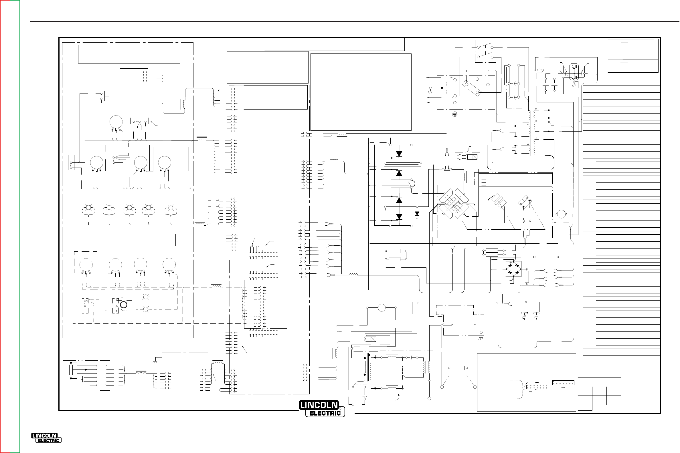
ELECTRICAL DIAGRAMS G-6
PRECISION TIG 275
®®
WIRING DIAGRAM - ENTIRE MACHINE - CODE 11159 (G5692-1)
RECEPTACLE
C
A
B B
10K A-B
F
E
D
C
MINIMUM
D
F
TM
AMPTROL
A
E
REMOTE
A
B
C
D
E
F
+-G
RGY
8
4
1
2
3
6
56
BW
+-
BW
+-
BW
+-
BW
+
-
G
331
6
5
4
3
2
1
2
3
4
5
7
1
8
7
6
5
4
3
2
1
J23
J22
321
322
313
314
315
316
317
318
319
320
311
312
J8
J9
5
9
8
3
7
2
1
6
4
331
10
411
W
403
404
405
406
407
408
409
410
401
402
8
7
6
5
4
3
2
1
220
G1
217
2
1W 221
R 222
11
3
10
2269
270
271
229A
6
5
4
3
2
1
233A
235
16
8
15
7
14
4
13
5
12
6
9
1
J11
L8
J10
J1
J5
J12
J4
J6
N.A.
8
6
2
3
4
5
7
1
J5A
N.B.
260
236
5
2
1
3
J7
401D
402
403
405
406
408
409
410
401B
401C
401D
232
H4 (575V)
F
W209
18VAC
X7
R210
201
X8
F
S
X5
X2
X1
T1
78VAC
S
204
115VAC
X9
X10
20VAC
X3
H2 (460V)
X6
262
263
63.5VAC
CR4
231A
231
115VAC
X4
CB1
15A
232
231
F
S
F
S
F
S
CR4
233B
234
48
26
233
01
233A
C8 C9
214
213
233A
231A
229A
271
270
216A
262
263
201
204
W209
R210
115VAC
R5
SV1
L3
C6
T2
C7
T3
GAPSPARK
L2
237
S
F
R6
FAN
260
235
233A
239 238
284 285
236B
236
231D
231E
231A
231E
233A
POS
D
NEG
S2
NO
X2
NC
TO GROUND PER
C
G
266A
S2A
265A
H
A
L1
E
F
ELECTRICAL CODE
NATIONAL
253
POS
B
252
W221
R222
265
266
G4
G3
G2
213
214
201
204
W209
R210
262
263
265
266
252
253
G1
G2
217
216
220
G3
220A
G4
218
SCR4 D1
X1
NEG
SCR3
POS
(+)
SCR1
SCR2
252
(-)
B
R
CLEVELAND , OHIO
G5692-1PRINT
A
L9
L10
L7
L6
L5
L12
L4
L13
L11
J3
N.D.
N.C.
L1 (U)
L2 (V)
C1
H4 H2
H1
250
S1
H1
C5
C4 C2
A
HIGH
MID
LOW
COM
251
21 3456 89
10
7
21 3456 89
10
7
J2
J3
21 3456 89
10
7
OR N.C.
407
L1 (U)
L2 (V)
319
322
313C
316B
315
316
317
311
312
313
318
313B
321
314
320
311A
316A
316C
311A
316A316B
F
C
S
E
N.E.
332
333
BW
334
335
B
W
332 B
W
333 B
W
334 B
W
335 B
W
12
11
10
9
8
6
5
4
3
1
2
7
12
11
10
9
8
6
5
4
3
1
2
7
6
4
10
9
216
218
SV2
N.F.
313A
216A
218A
217A
R8A
269
R7C
218B
R7D 271A
218A
R7A
230
R7B
268
R8B
229
GND6
GND6
217A
344
345
343
4
3
2
1347
J7
316D
346
8
6
2
3
4
5
7
1
J13
343
344
345
346
347
G+
-
W
B
401
404
411
401A
401B
R
+-
BW
413
413
W 2
1J20
S2
229
316C
N.A. CONNECTION IS PIN TO PIN BETWEEN J23 AND J5.
N.B. ROBOTIC INTERFACE CONNECTION.
N.C. REMOVE JUMPER PLUG IN J3 WHEN INSTALLING
TIG OPTION PC BOARD.
N.D. DISCONNECT JUMPER LEAD BETWEEN PIN 1 AND
PIN 2 IN J3 TO DOUBLE PREFLOW & POSTFLOW TIMES.
N.E. DISPLAY TOGGLE SHOWN IN MIN AMP POSITION.
N.F. PLUGS INTO LOWER SWITCHED RECEPTACLE.
GND6
575 V
CONNECT STRAP TO HIGH (H4) (AS SHOWN)
CONNECTER LA BRIDE SUR HAUT (H4)
(COMME ILLUSTRÉ)
SUJETADOR DE CONEXIÓN A ALTO (H4)
(COMO SE MUESTRA)
460 V
CONNECT STRAP TO LOW (H2)
CONNECTER LA BRIDE SUR BAS (H2)
SUJETADOR DE CONEXIÓN A BAJO (H2)
METER
COMPTEUR
MEDIDOR
DISPLAY
AFFICHAGE
PANTALLA
FREQ
BACKGROUND
ARRIÈRE PLAN
FONDO
GROUND
TERRE
TIERRA
RECONNECT PANEL
PANNEAU DE RECONNEXION
BYPASS/STABILIZER PC BOARD
CI DÉRIVATION/STABILISATEUR
T1 PRIMARY
THERMOSTAT
T1 PRIMAIRE
THERMOSTAT
T1 SECONDARY
THERMOSTAT
T1 SECUNDARIO
THERMOSTAT
ÉCLATEUR
ABERTURA
DE CHISPA
CONTROL PANEL (VIEWED FROM REAR)
PANNEAU DE COMMANDE (VIEWED FROM REAR)
PANEL DE CONTROL (VISTO DESDE ATRÁS)
ADVANCED CONTROL PANEL (OPTIONAL)
PANNEAU DE COMMANDE AVANCÉ (OPTION)
PANEL DE CONTROL AVANZADO (OPCIONAL)
PRISE À DISTANCE
RECEPTÁCULO REMOTO
PROTECTION PCB
CI PROTECTION
PCB DE PROTECCIÓN
TIG OPTION PCB
CI OPTION TIG
PCB DE OPCIÓN
TIG
CONTROL PC BOARD
CI DE COMMANDE
TABLEAU DE
TARJETA ELECTRONICA
DE CONTROL
N.A. CONNEXION CONTACT-CONTACT ENTRE J23 ET J5
N.B. CONNEXION INTERFACE ROBOTIQUE
N.C. ENLEVER LA FICHE CAVALIER EN J3 QUAND ON INSTALLE LE CI EN
OPTION TIG
N.D. DÉCONNECTER LE CÂBLE DU CAVALIER ENTRE LES CONTACTS 1 ET
2 DANS J3 POUR DOUBLER TEMPS DE PRÉGAZ ET POSTGAZ.
N.E. AFFICHE LA BASCULE ILLUSTRÉE EN POSITION A MINIMUM.
N.F. SE BRANCHE LA PRISE À INTERRUPTEUR INFÉRIEURE.
N.A. LA CONEXIÓN ES DE PIN A PIN ENTRE J23 Y J5.
N.B. CONEXIÓN DE LA INTERFAZ ROBÓTICA.
N.C. REMUEVA EL CONECTOR DE PUENTE EN J3 CUANDO INSTALE LA
TARJETA DE PC TIG OPCIONAL.
N.D. DESCONECTE EL CABLE DEL PUENTE ENTRE EL PIN 1 Y PIN 2 EN J3
PARA DUPLICAR LOS TIEMPOS DE PRE Y POSTFLUJO.
N.E. EL INTERRUPTOR DE PALANCA DE LA PANTALLA SE MUESTRA EN LA
POSICIÓN MÍNIMA DE AMPERIOS.
N.F. ENCHUFES EN RECEPTÁCULO CONMUTADO INFERIOR.
PRECISION TIG 275 WIRING DIAGRAM
SCHÉMA DE CÂBLAGE DIAGRAMAS DE CABLEADO
ALA TERRE SELON LE CODE
ÉLECTRIQUE NATIONAL
ATIERRA CONFORME EL CÓDIGO
ELÉCTRICO NACIONAL
PANEL DE RECONEXIÓN
A-C, D-E, B-F
B-D, C-E, A-F, G-HDC+
DC-
AC
B-D, A-E, C-F, G-H
S2 S2A
CLOSED FERMÉ CERRADO
OPEN OUVERT ABIERTO
CLOSED FERMÉ CERRADO
VENTILATEUR
VENTILADOR TARJETA ELECTRONICA DE
DERIVACIÓN /
ESTABILIZADOR
ARC STARTER AS'BLY
ENSEMBLE DÉMARREUR D'ARC
ENSAMBLE DE ARRANCADOR DE
ARCO
REAR
ELECTRODE
ÉLECTRODE ARRIÈRE
ELECTRODO POSTERIOR
FRONT
ELECTRODE
ÉLECTRODE AVANT
ELECTRODO FRONTAL
WORK
PIÈCE
TRABAJO VIEW OF CONNECTOR ON PC BOARD
ELECTRICAL SYMBOLS PER E1537.
SYMBOLES ÉLECTRIQUES SELON E1537
SÍMBOLOS ELÉCTRICOS CONFORME A E1537
COMPONENT VALUE UNITS:
RESISTORS: OHMS/WATTS
CAPACITORS: MFD/VOLTS
8
0F CONNECTOR J5
EXAMPLE: THIS IS PIN 1
32
21
8
CONNECTOR PIN NUMBERS: NOMBRE DE CONTACTS CONNECTEURS
NÚMEROS DE PINES DE CONECTORES:
7
14
1
3
J5
UNITÉS DE VALEUR DES COMPOSANTS:
RÉSISTANCES: OHMS/WATTS
CONDENSATEURS: MFD/VOLTS
EXEMPLE: C'EST LE CONTACT 1
DU CONNECTEUR J5
EJEMPLO: ESTE ES EL PIN 1 DEL
CONECTOR J5 VUE DES CONNECTEURS SUR CI
VISTA DEL CONECTOR EN LA
TARJETA ELECTRONICA
UNIDADES DE VALOR DE COMPONENTES:
RESISTORES: OHMS/WATTS
CAPACITORES: MFD/VOLTIOS
C1,C2 POWER FACTOR CAPACITORS, 50/460
C4,C5 BY-PASS CAPACITORS, .0047
C6 HIGH VOLTAGE CAPACITOR, .0015/12kV
C7 PHASE SHIFT CAPACITOR, 15uF/250VAC
C8,C9 HIGH FREQ PROTECTION CAPACITORS, .22/400
CB1 CIRCUIT BREAKER, 15 AMP
CR4 12V DC RELAY COIL
D1 FREE WHEELING DIODE
L1 OUTPUT INDUCTOR (CHOKE)
L2,L3 HIGH FREQ INDUCTORS
L4 -L13 RF TOROID CHOKES
R5 PHASE SHIFT RESISTOR, 200/100
R6 HOLDING RESISTOR, 50/225
S1 INPUT POWER SWITCH
S2 POLARITY SWITCH
S2A MICROSWITCH ON POLARITY SWITCH
S3 MENU SWITCH
SCR1,2,3,4 MAIN POWER SCR'S
SV1 GAS SOLENOID VALVE, 115VAC
SV2 WATER SOLENOID VALVE, 115VAC (OPTIONAL)
T1 MAIN TRANSFORMER
T2 HIGH VOLTAGE TRANSFORMER
T3 HIGH FREQ TRANSFORMER
CONDENSATEURS FACTEUR DE PUISSANCE, 50/460
CAPACITORES DE FACTOR DE POTENCIA, 50/460
C4,C5 CONDENSATEURS DÉRIVATION , .0047
CAPACITORES DE DERIVACIÓN, .0047
CONDENSATEUR HAUTE TENSION, .0015/12kV
CAPACITOR DE ALTO VOLTAJE, .0015/12kV
CONDENSATEUR, DÉPHASAGE, 15Mf/250VCA
CAPACITOR DE CAMBIO DE FASE 15uf/250VCA
CONDENSATEURS DE PROTECTION HF, .22/400
CAPACITORES DE PROTECCIÓN CONTRA ALTA
FRECUENCIA, .22/400
DISJONCTEUR, 15 AMP
INTERRUPTOR AUTOMÁTICO, 15 AMPS
CR4 BOBINE RELAI DE 12V CC
BOBINA DE RELEVADOR DE 12V DE DC
DIODE ROUE LIBRE
DIODO DE RUEDA LIBRE
L1 INDUCTEUR DE SORTIE (STARTER)
INDUCTOR DE SALIDA (ESTABILIZADOR)
INDUCTANCES HF
INDUCTORES DE ALTA FRECUENCIA
L4 -L13 STARTERS TOROÏDE FRÉQUENCE RADIO
ESTABILIZADORES TOROIDAL RF
RÉSISTANCE DÉPHASAGE, 200/100
RESISTOR DE CAMBIO DE FASE, 200/100
RÉSISTANCE DE MAINTIEN, 50/225
RESISTOR DE SOSTENIMIENTO, 50/225
R7A,R7B,
R7C,R7D,
R8A, R8B
RÉSISTANCE, 5/50, RESISTORES, 5/50
INTERRUPTEUR DE PUISSANCE D’ENTRÉE
INTERRUPTOR DE ENERGÍA DE ENTRADA
INTERRUPTEUR DE POLARITÉ
INTERRUPTOR DE POLARIDAD
MICRORUPTEUR SUR SÉLECTEUR DE POLARITÉ
MICROINTERRUPTOR EN EL INTERRUPTOR DE
POLARIDAD
INTERRUPTEUR MENU
INTERRUPTOR DE MENÚ
REDRESSEURS DE PUISSANCE PRINCIPAUX
SCR'S DE ALIMENTACIÓN PRINCIPAL
SV1 SOUPAPE SOLÉNOÏDE DE GAZ, 115 VAC
VÁLVULA DE SOLENOIDE DE GAS, 115 VCA
SOUPAPE SOLÉNOÏDE À EAU, 115 VAC
VÁLVULA DE SOLENOIDE DE AGUA, 115 VCA
T1 TRANSFORMATEUR PRINCIPAL
TRANSFORMADOR PRINCIPAL
TRANSFORMATEUR HAUTE TENSION
TRANSFORMADOR DE ALTO VOLTAJE
TRANSFORMATEUR HAUTE FRÉQUENCE
TRANSFORMADOR DE ALTA FRECUENCIA
T2
T3
S2A
S3
SCR1,2,3,4
SV2
R5
R6
S1
S2
C8,C9
CB1
D1
L2,L3
RESISTOR, 5/50
C1,C2
C6
C7
R7A, R7B,
R7C, R7D,
R8A, R8B
LEAD COLORING CODE:
CODE DE COULEUR DES CÂBLES:
CÓDIGO DE COLORES DE CABLES:
B-BLACK
NOIR
NEGRO
O-ORANGE
NARANJA
G-GREEN
VERT
VERDE
R-RED
ROUGE
ROJO
B-BLUE
BLEU
AZUL
W-WHITE
BLANC
BLANCO
Y-YELLOW
JAUNE
AMARILLO
R4
R2 R1 R3
R9 R10 R11 R12
LOCAL
TIG
MAX OUTPUT
RENDEMENT
SALIDA
ON TIME DOWN SLOPE
VERS LE BAS PENTE
ABAJO CUESTA
ÀL'HEURE
EL TIEMPO
BALANCEADO
ÉQUILIBRE
BALANCE
STICK
ÉLECTRODE
VARILLA
REMOTE
À DISTANCE
REMOTO
SALIDA
RENDEMENT
MAX OUTPUT
2 STEP
2 TEMPS
2 PASO
4 PASO
4 TEMPS
4 STEP SPOT
TACHE
PUNTO
PULSE
PULSÉ
PULSACIÓN PULSACIÓN
PULSÉ
PULSE
PUNTO
TACHE
SPOT
POST FLOW
ÉCOULEMENT DE POTEA
FLUJO DEL POSTE
MIN. OUTPUT
RENDEMENT
SALIDA
STICK
ÉLECTRODE
VARILLA
BALANCE
ÉQUILIBRE
BALANCEADO
REMOTE
À DISTANCE
REMOTO FLUJO DEL POSTE
ÉCOULEMENT DE POTEA
POST FLOW
TERMAL
THERMIQUE
THERMAL
G-6
NOTE: This diagram is for reference only. It may not be accurate for all machines covered by this manual. The wiring diagram specific to your code is pasted inside one of the enclosure panels of your machine.
Return to Section TOC Return to Section TOC Return to Section TOC Return to Section TOC
Return to Master TOC Return to Master TOC Return to Master TOC Return to Master TOC
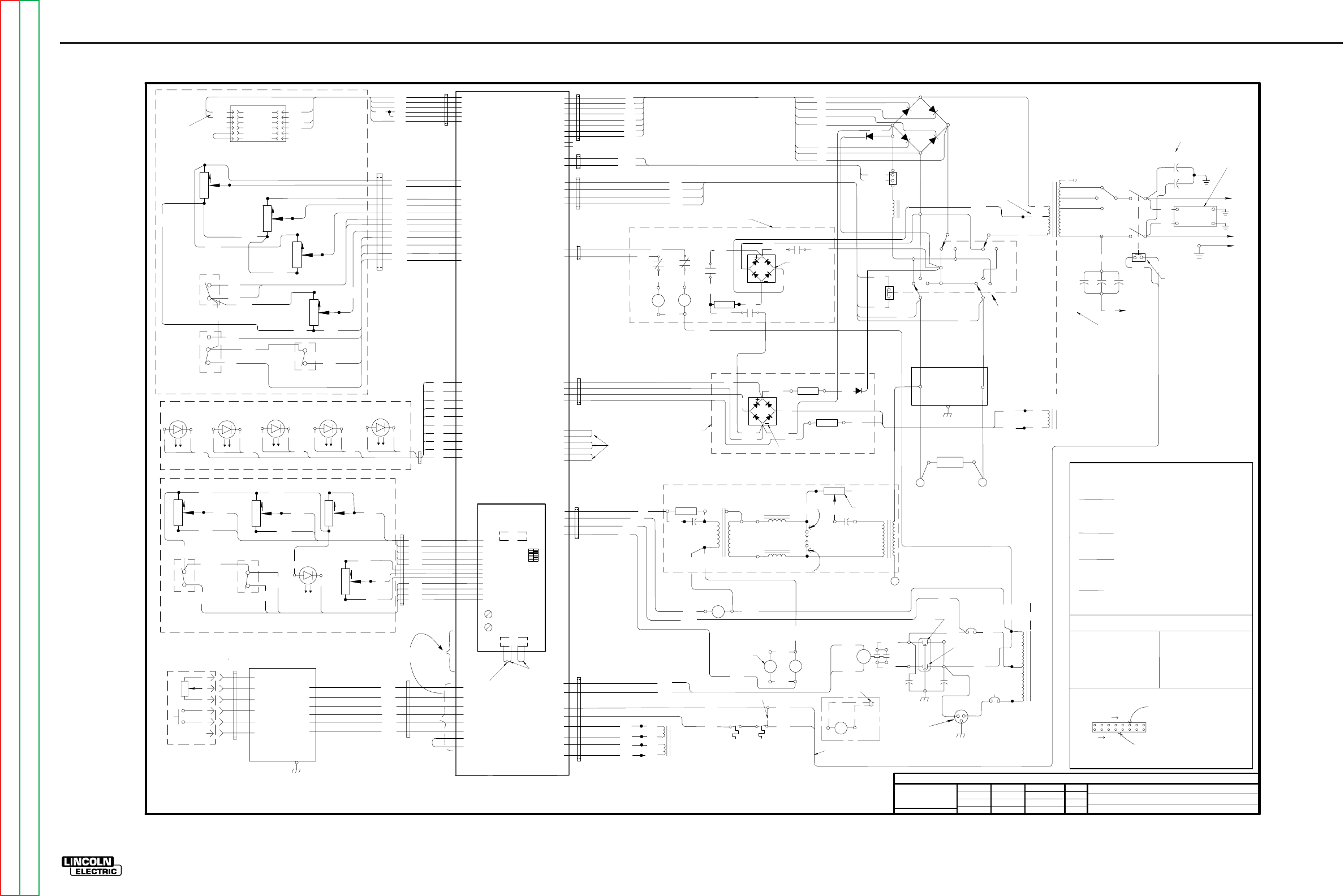
Return to Section TOC Return to Section TOC Return to Section TOC Return to Section TOC
Return to Master TOC Return to Master TOC Return to Master TOC Return to Master TOC
ELECTRICAL DIAGRAMS G-7
PRECISION TIG 275
®®
SCHEMATIC - ENTIRE MACHINE - BELOW CODE 11000 (G4075)
XB-UF
01-29-02
NONE
MACHINE SCHEMATIC
PRECISION TIG
4075
TN
TN
3-8-2002A
THIS DOCUMENT CONTAINS PROPRIETARY INFORMATION OWNED BY LINCOLN GLOBAL, INC. AND MAY NOT BE DUPLICATED, COMMUNICATED
TO OTHER PARTIES OR USED FOR ANY PURPOSE WITHOUT THE EXPRESS WRITTEN PERMISSION OF LINCOLN GLOBAL, INC.
PROPRIETARY & CONFIDENTIAL:
EN-170
UNLESS OTHERWISE SPECIFIED TOLERANCE
MANUFACTURING TOLERANCE PER E2056
ON 2 PLACE DECIMALS IS ±.02
ON 3 PLACE DECIMALS IS ±.002
ON ALL ANGLES IS ±.5 OF A DEGREE
MATERIAL TOLERANCE (" ") TO AGREE
t
WITH PUBLISHED STANDARDS.
DO NOT SCALE THIS DRAWING
DRAWN BY:
ENGINEER:
DESIGN INFORMATION
APPROVED:
REFERENCE:
SUPERSEDING:
EQUIPMENT TYPE:
SUBJECT:
SCALE: DATE: DRAWING No.:
G
SOLID EDGE
"X" INFO Chg. Sheet No.
SCR4 SCR1
SCR3 SCR2
MAIN
RECTIFIER
D1
OUTPUT
INDUCTOR
AC
DC
DC
DC
DC AC AC
AC
++
--
RECEPTACLE
R1
POLARITY
SWITCH
SHUNT
FRONT WORK
SV1
GAS
SOLENOID
CB1
115V/15A
FAN
X3
X4
250
SEE NOTE A
MAIN
TRANSFORMER
RECONNECT
PANEL
X2
X1
H1
H2
H3
H4
L2
L1
ELECTRICAL SYMBOLS PER E1537
+
-
TM
CLOSED
IN DC
REMOTE
HIGH FREQ.
TRANSFORMER
115 V
RECEPTACLE
3KV
.0047/
400A/200mV
S2
50/100
OPTIONAL AMPTROL REMOTE
CONTROL AND ARC START SWITCH
T2
S
F
C6
.0015/12KV
50/60HZ MACHINES ONLY
C4
C5
C1 C3
SPARK
GAP
R5
200/100
LEAD #250 CONNECTS TO "HIGH" TERMINAL ON
FROM MAIN TRANSFORMER (T1)
RECONNECT PANEL, ALONG WITH CORRECT LEAD
208/230/460
LEAD #250 CONNECTS TO THE H5 LEAD OF
THE MAIN TRANSFORMER (T1)
230/460/575
LEAD #250 CONNECTS TO THE "MID" TERMINAL
ON THE RECONNECT PANEL, ALONG WITH CORRECT
LEAD FROM THE MAIN TRANSFORMER (T1)
NOTE A:
CONNECTS ACCORDING TO THE INPUT VOLTAGE
LEAD #250 FROM POWER FACTOR CAPACITORS
B-BLACK
R-RED
Y-YELLOW
G-GREEN
U-BLUE
W-WHITE
COMPONENT VALUE
UNITS:
CAPACITORS:
MFD/VOLTS
RESISTORS:
OHMS/WATTS
LEAD COLORING CODE:
CONNECTOR PIN NUMBERS:
VIEW OF CONNECTOR ON PC BOARD
123 8
916
LATCH
EXAMPLE: THIS PIN IN
CONNECTOR J11 IS "6J11"
O-ORANGE
C7
15/250
220V 2A
RECEPTACLE
CB2
220V/5A
H5
HIGH VOLTAGE
TRANSFORMER
H1
220/380/415
L1
L2
L3
C2
T3
240
238A
PRESENT ONLY ON
PRECISION TIG 375
R13 HI-FREQ INTENSITY
REAR
ELECTRODE
(STICK WELDING)
(TIG WELDING)
HOLDING RESISTOR
COOLER
RECEPTACLE
(BOTTOM)
(TOP)
231A
231B
231A
231D
FAN
231E
231F
260A
PRECISION
TIG 375 ONLY
X13
R14
CR2
C8 C9
.22/400V .22/400V
CR4
233B
234
(12VDC)
COOLER RELAY 233 232
231
236B
237
238
239
225A 228
DC
+
DC-
DC+
DC-
224
CR3
223
226
227A
CR3
223
227
225
CR2
CR3
258
256
257
CR3
CR2
255
231C
STICK OCV BOOST CIRCUIT,
PRESENT ONLY ON PRECISION TIG 375
OCV BOOST
RECTIFIER
AC
BOOST
DC
BOOST
271A
220C 220A
220B
268
R8
5/50
R7
20/100 D2
286
DC TIG BACKGROUND
CIRCUIT
267
X5
X6
63.5V
268
267
269
270
BACKGND AC IN (63.5VAC)
271
1J4
5J4
G1
G2
G3
G4
218
217
216
220
SCR1,SCR2 CATHODE
SCR3 CATHODE
SCR4 CATHODE
SCR3,SCR4 ANODE
SCR1 GATE
SCR2 GATE
SCR3 GATE
SCR4 GATE
216
G4
G1
G2
G3
220
217
218
220A
FREE WHEELING DIODE
1J12
5J12
115VAC IN AC STICK
115VAC IN DC STICK
2J4
4J4
9J4
6J4
10J4
7J4
BACKGND AC OUT (63.5VAC) IN DC TIG
BACKGND FILTER CAP., POS
BACKGND FILTER CAP., NEG
3J11
11J11
2J11
10J11
BACKGND DIODE
BACKGND RESISTOR
BACKGND TRIAC
CURRENT LIMITING RESISTOR
BACKGND RECTIFIER
X14
231B
231E
236
TOROID
TOROID
HI-FREQ (115VAC)
GAS (115VAC)
FAN (115VAC)
235
260
265
266
252 253
MICRO SWITCH ON POLARITY SWITCH
VOLT FEEDBACK, ELECTRODE
VOLT FEEDBACK, WORK
265
266
252
253
MICRO SWITCH ON POLARITY SWITCH
TOROID
6J11
12J11
1J11
9J11
POWER SWITCH
MICRO SWITCH
215
212
212
215
PRECISION TIG 375
ONLY
PRECISION TIG 375
ONLY
PRECISION TIG 275 ONLY
262
263
214
213
TSTAT
TSTAT
COOLER, +12VDC IN TIG WELDING
COOLER, COMMON
262
263
5J11
13J11
4J11
14J11
TOROID
233A
235
233A
260
233A
115VAC IN
6J12
3J12
2J12
4J12
TOROID
X7
X8
X9
X10
20VAC
CONTROL BOARD SUPPLY
20VAC
TRIGGER CIRCUIT
8J11
16J11
7J11
15J11
209
210
201
204
AUX. WINDINGS OF
MAIN TRANSFORMER T1
PRIMARY TSTAT SECONDARY TSTAT
(OF MAIN TRANSFORMER T1)
3J4
8J4
X
X
TOROID
R 222(-)
W 221(+)
W 221
R 222
SHUNT (+)
SHUNT (-)
1J6
2J6
TOROID
+5V
DECIMAL PT. IN
IN (+)
COM
IN (-)
DECMAL PT.OUT
1J8
2J8
3J8
4J8
5J8
6J8
301
302
303
304
304A
306
TOROID
5
4
3
2
1
5
4
3
2
1
66
301
303
304B
306
302
METER
(VIEWED FROM REAR)
304B
R1 311
312
313
+10V
COM
PRESET (0 - 10V)
1J9
2J9
3J9
MAX
OUTPUT
CW
MIN
OUTPUT
CW
313B
314
320 MIN OUTPUT (0 - 1.5V)
+1.5V
R4
CW
CW
R2
CW
BALANCE
313C
311A
322 12J9
4J9
10J9
BALANCE (0 - 10V)
316
317
LOCAL
REMOTE
316
317
6J9
7J9
+15V
REMOTE (+15V)
CW
R3
CW
A
MIN A
VOLT
DISPLAY SWITCH
316B
316C
321
315 319
STICK
TIG
MODE SWITCH
316A
313A
321
315
319
318
11J9
5J9
9J9
8J9
STICK (+15V)
POSTFLOW (0 - 15V)
TOROID
STICK AUTO BALANCE REMOTE
(RED) (GREEN) (GREEN)
GAS
(GREEN)
THERMAL
(YELLOW)
BWBWBWBW
331 332 333
BW
334 335
331
331
332
332
333
333
334
334
335
335
B
W
B
W
B
W
B
W
B
W
6J10
1J10
7J10
2J10
8J10
3J10
9J10
4J10
10J10
5J10
TOROID
LED LIGHTS
R9
CW CW
R10
FREQUENCY ON TIME
CW
R12
DOWN SLOPE
401C 401D
402
403
405
406
407
CW
R11
BACK GROUND
B
W
PULSE
ON
OFF
TRIGGER
4-STEP
2-STEP
401B
404
401A
411
401
408
409
410
FREQ. (.08 - 15V)
402
403
405
406
407
PULSE
(GREEN)
ON TIME (1-15V)
DOWNSLOPE
2J1
3J1
5J1
6J1
7J1
404
401
411
W
PULSE ON (15V)
+15V
2-STEP (15V)
PULSE LED
8J1
9J1
10J1
4J1
1J1
11J1
12J1
TOROID
A
B
C
D
E
F
U
N
R
B
W
10K
PROTECTION
PCB
4J22
1J22
2J22
3J22
6J22
5J22
A
B
C
D
E
F
2J5
3J5
4J5
5J5
7J5
6J5
8J5
1J5
TOROID TOROID
2J23
3J23
4J23
5J23
7J23
1J23
2J5A
3J5A
4J5A
5J5A
7J5A
1J5A
6J5A
8J5A
MOVE THIS PLUG FROM
J5 TO J5A FOR ROBOTIC INTERFACE
ADVANCED CONTROL
PCB
(OPTIONAL ON PT275)
J2
J3 123
4
WHEN ADVANCED CONTROL
PCB IS NOT INSTALLED
DISCONNECT FOR
DOUBLE PRE/POST FLOW
DIP SWITCH
(ADVANCED FEATURES
SELECTION)
HOT START TRIMMER
ARC FORCE TRIMMER
( SCHEMATIC G3908-X)
(SCHEMATIC G4039-X)
(SCHEMATIC S22530)
BYPASS/STABILIZER
PCB
(SCHEMATIC M16115)
ADVANCED CONTROL PANEL (OPTIONAL ON PT275)
1J7
3J7
2J7
5J7
4J7
6J7
PT375 ONLY
CONTROL PCB
POST FLOW
8/300
10K
10K
10K
10K
10K 10K 10K
10K
LOW
MID
HIGH
SV2
SOLENOID
OPTIONAL
WATER
PLUGGED TO
COOLER RECEPTACLE
(SHOWN IN REMOTE)
(SHOWN IN STICK)
DISPLAY VOLT (+15V)
DISPLAY MIN A (+15V)
313A
318
CONTROL PANEL
(SHOWN IN 2-STEP)(SHOWN PULSE ON)
MAX
WIPER
MIN
PT375 ONLY
N.O.
N.C.
115VAC
105VAC
3/25
(115VAC)
TOP FAN BOTTOM FAN
(115VAC) (115VAC)
(115VAC)
5.5 OHMS
TYP. 14.5 KOHMS
TYP. 12.5 OHM TYP.
12.5 OHM TYP.
KIT
ELECTRODE
T1
T1
T1
T1
223
205mV BETWEEN
IN(+) & IN(-) IS
205A OR 20.5V
IN(+)
IN(-)
HI-FREQ CIRCUIT
460/575
LEAD #250 CONNECTS TO THE "LOW" TERMINAL
ON THE RECONNECT PANEL, ALONG WITH CORRECT
LEAD FROM THE MAIN TRANSFORMER (T1)
POWER FACTOR
CAPACITORS
PT375: STANDARD, C1=C2=C3=60/460
PT275: OPTIONAL, C1=C2=50/460
C3 NOT PRESENT
313
BYPASS PCB
L1A
L2A
50/60HZ MACHINE ONLY
BYPASS ASSEMBLY
50HZ MACHINE ONLY
SCHE. S24206-X
G-7
NOTE: This diagram is for reference only. It may not be accurate for all machines covered by this manual.
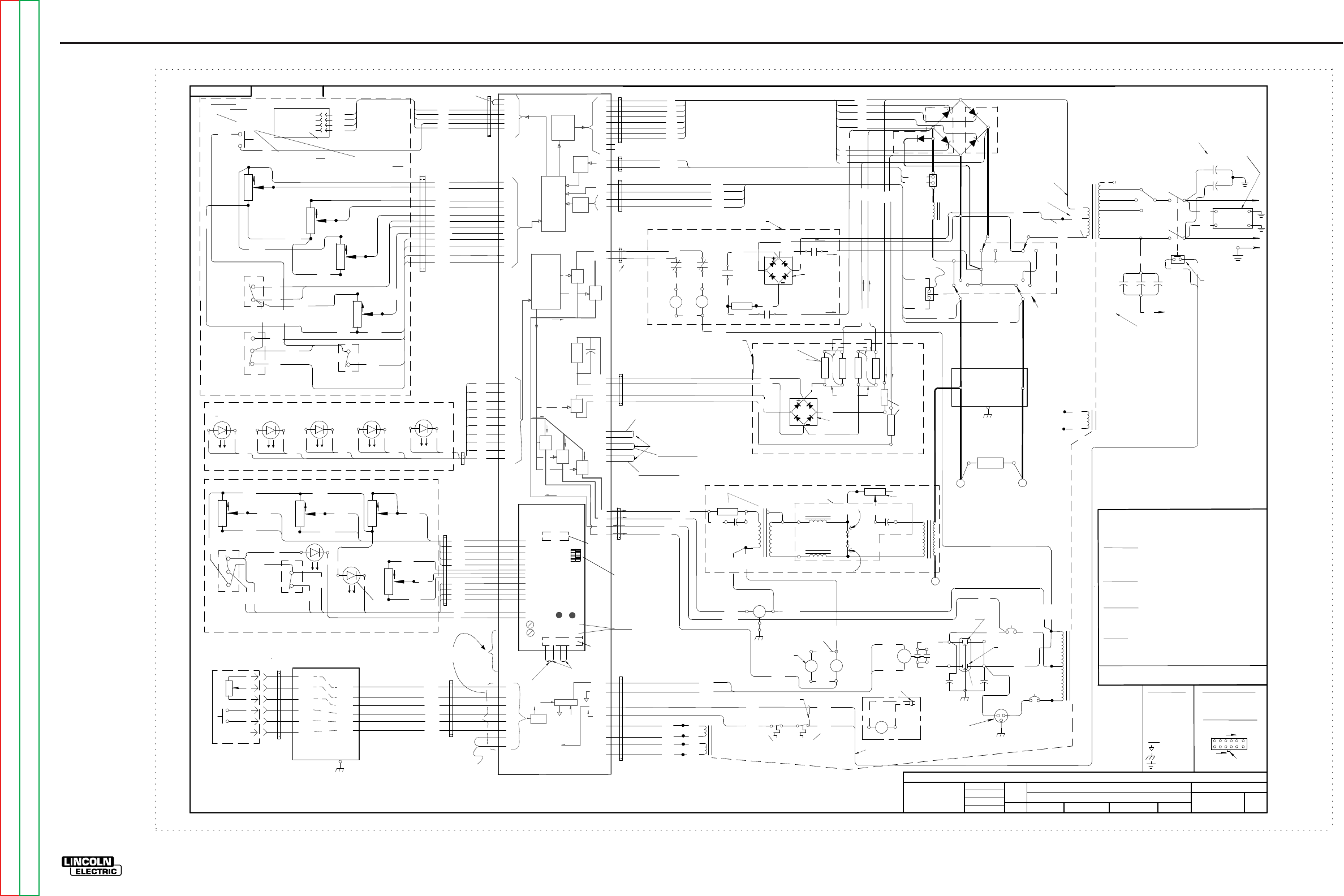
ELECTRICAL DIAGRAMS G-8
PRECISION TIG 275
®®
SCHEMATIC - ENTIRE MACHINE - ABOVE CODE 11000 (G5691)
EN-170
SOLID EDGE
ENGINEERING CONTROLLED
MANUFACTURER: No RELEASED FROM X A.02
G5691
PRECISION TIG
MACHINE SCHEMATIC
NONE
G4075
bburkhart
burkhart
-
DRAWN BY:
DESIGN INFORMATION
ENGINEER:
APPROVED: REFERENCE:
EQUIPMENT TYPE:
SUBJECT:
SCALE:
MATERIAL
DISPOSITION: APPROVAL
DATE: PROJECT
NUMBER:
NA CRM38261
1
PAGE ___ OF ___
1
DOCUMENT
NUMBER: DOCUMENT
REVISION:
THIS DOCUMENT CONTAINS PROPRIETARY INFORMATION OWNED BY LINCOLN GLOBAL, INC. AND MAY NOT BE DUPLICATED, COMMUNICATED
TO OTHER PARTIES OR USED FOR ANY PURPOSE WITHOUT THE EXPRESS WRITTEN PERMISSION OF LINCOLN GLOBAL, INC.
PROPRIETARY & CONFIDENTIAL:
A
THE INFORMATION ON THIS
PRINT IS FOR REFERENCE
ONLY. COMPONENTS AND
CIRCUITRY MAY BE DIFFERENT
FROM AN ACTUAL MACHINE. 7-27-2007
CHANGE DETAIL:
IF PRINTED
@A1 SIZE
UNITS:
NONE
G5691
LEAD COLOR CODE:
B-BLACK OR GRAY
G-GREEN
O-ORANGE
R-RED OR PINK
U-BLUE
W-WHITE
Y-YELLOW
COMPONENT VALUE UNITS:
CAPACITOR: MFD/VOLTS
RESISTOR: OHMS/WATTS
CONNECTOR PIN NUMBERS:
VIEW OF CONNECTOR ON PC BOARD
126
712
LATCH
EX. 12 PIN CONNECTOR
LABELS:
COMMON
FRAME GROUND
EARTH GROUND
SCR4 SCR1
SCR3 SCR2
MAIN
RECTIFIER
D1
OUTPUT
INDUCTOR
AC
DC
DC
DC
DC AC AC
AC
++
--
RECEPTACLE
R1
POLARITY
SWITCH
SHUNT
FRONT WORK
SV1
GAS
SOLENOID
CB1
115V/15A
FAN
X3
X4
250
SEE NOTE A
MAIN
TRANSFORMER
RECONNECT
PANEL
X2
X1
H1
H2
H3
H4
L2
L1
ELECTRICAL SYMBOLS PER E1537
+
-
TM
CLOSED
IN DC
REMOTE
HIGH FREQ.
TRANSFORMER
115 V
RECEPTACLE
3KV
.0047/
400A/200mV
S2
50/100W
OPTIONAL AMPTROL REMOTE
CONTROL AND ARC START SWITCH
T2
S
F
C6
.0015/12KV
50/60HZ MACHINES ONLY
C4
C5
C1 C3
SPARK
GAP
R5
200/100W
LEAD #250 CONNECTS TO "HIGH" TERMINAL ON
FROM MAIN TRANSFORMER (T1)
RECONNECT PANEL, ALONG WITH CORRECT LEAD
208/230/460
LEAD #250 CONNECTS TO THE H5 LEAD OF
THE MAIN TRANSFORMER (T1)
230/460/575
LEAD #250 CONNECTS TO THE "MID" TERMINAL
ON THE RECONNECT PANEL, ALONG WITH CORRECT
LEAD FROM THE MAIN TRANSFORMER (T1)
NOTE A:
CONNECTS ACCORDING TO THE INPUT VOLTAGE
LEAD #250 FROM POWER FACTOR CAPACITORS
C7
15/250V
220V 2A
RECEPTACLE
CB2
220V/5A
H5
HIGHVOLTAGE
TRANSFORMER
H1
220/380/415
L1
L2
L3
C2
T3
240
238A
PRESENT ONLY ON
PRECISION TIG 375
R13
HI-FREQ INTENSITY
REAR
ELECTRODE
(STICK WELDING)
(TIG WELDING)
HOLDING RESISTOR
COOLER
RECEPTACLE
(BOTTOM of plug)
(TOP of plug)
231A
231B
231A
231D
FAN
231E
231F
260A
PRECISION
TIG 375 ONLY
X13
R14
CR2
C8 C9
.22/400V .22/400V
CR4
233B
234
(12VDC)
COOLER RELAY 233 232
231
236B 237
238
239
225A 228
DC+
DC-
DC+
DC-
224
CR3
226
227A
CR3
223
227
225
CR2
CR3
258
256
257
CR3
CR2
255
231C
AC & DC STICK OCV BOOST CIRCUIT,
PRESENT ONLY ON PRECISION TIG 375
OCV BOOST
RECTIFIER
AC
BOOST
DC
BOOST
271A
229
229A
268
R8B
R7D
BACKGROUND CIRCUIT
ENABLED IN BOTH TIG
& STICK, AC & DC
X5
X6
63.5V
269
270
BACKGND AC IN
271
1J4
5J4 G1
G2
G3
G4
218
217
216
220
SCR1,SCR2 CATHODE
SCR3 CATHODE
SCR4 CATHODE
SCR3,SCR4 ANODE
SCR1 GATE
SCR2 GATE
SCR3 GATE
SCR4 GATE
216
G4
G1
G2
G3
220
217
218
1J12
5J12
115VAC IN
AC STICK
115VAC IN
DC STICK
2J4
4J4
9J4
6J4
10J4
7J4
BACKGND AC OUT
BACKGND FILTER CAP., POS
BACKGND FILTER CAP., NEG
3J11
11J11
2J11
10J11
BACKGND
RECTIFIER
X14
231B
231E
236
TOROID
TOROID
HI-FREQ (115VAC)
GAS (115VAC)
FAN (115VAC)
235
260
265
266
252 253
MICRO SWITCH ON POLARITY SWITCH
VOLT FEEDBACK, ELECTRODE
VOLT FEEDBACK, WORK
265
266
252
253
MICRO SWITCH ON POLARITY SWITCH
TOROID
6J11
12J11
1J11
9J11
POWER SWITCH
MICRO SWITCH
215
212
212
215
PRECISION TIG 375
ONLY
PRECISION TIG 375
ONLY
PRECISION TIG 275 ONLY
262
263
214
213
TSTAT
TSTAT
COOLER, +12VDC IN TIG WELDING
COOLER, COMMON
262
263
5J11
13J11
4J11
14J11
TOROID
233A
235
233A
260
233A
115VAC IN
6J12
3J12
2J12
4J12
TOROID
X7
X8
X9
X10
20VAC
CONTROL BOARD SUPPLY
20VAC
TRIGGER CIRCUIT
8J11
16J11
7J11
15J11
209
210
201
204
AUX. WINDINGS OF
MAIN TRANSFORMER T1
PRIMARY TSTAT SECONDARY TSTAT
(OF MAIN TRANSFORMER T1)
3J4
8J4 X
X
TOROID
R 222(-)
W 221(+)
W 221
R 222
SHUNT (+)
SHUNT (-)
1J6
2J6
TOROID
1J13
2J13
3J13
4J13
5J13
6J13
343
344
345
346
TOROID
4
3
2
1344
345
343
METER
R1 311
312
313
+10V
COM
PRESET (0 - 10V) 1J9
2J9
3J9
MAX
OUTPUT
CW
MIN
OUTPUT
CW
313B
314
320 MIN OUTPUT (0 - 1.5V)
+1.5V
R4
CW
CW
R2 CW
BALANCE
313C
311A
322 12J9
4J9
10J9
BALANCE (0 - 10V)
316
317
LOCAL
REMOTE
316
317
6J9
7J9
+15V
REMOTE (+15V)
CW
R3
CW
A
MIN A
VOLT
DISPLAY SWITCH
316B
316C
321
315 319
STICK
TIG
MODE SWITCH
316A
313A
321
315
319
318
11J9
5J9
9J9
8J9
STICK (+15V)
POSTFLOW (0 - 15V)
TOROID
STICK AUTO BALANCE REMOTE
(RED) (GREEN) (GREEN) GAS
(GREEN) THERMAL
(YELLOW)
BWBWBWB W
331 332 333
BW
334 335
331
331
332
332
333
333
334
334
335
335
B
W
B
W
B
W
B
W
B
W
6J10
1J10
7J10
2J10
8J10
3J10
9J10
4J10
10J10
5J10
TOROID
LED LIGHTS
R9
CW CW
R10
FREQUENCY ON TIME
CW
R12
DOWN SLOPE
401C 401D
402
403
405
406
407
CW
R11
BACK GROUND
B
W
PULSE
OFF
TRIGGER
4-STEP
2-STEP
401B
404
401A
411
401
408
409
410
FREQ. (.08 - 15V)
402
403
405
406
407
PULSE
(GREEN)
ON TIME (1-15V)
DOWNSLOPE
2J1
3J1
5J1
6J1
7J1
404
401
411
W
PULSE ON (15V)
+15V
2-STEP (15V)
PULSE LED
8J1
9J1
10J1
4J1
1J1
11J1
12J1
TOROID
A
B
C
D
E
F
U
N
R
B
W
10K
PROTECTION
PCB
4J22
1J22
2J22
3J22
6J22
5J22
A
B
C
D
E
F
2J5
3J5
4J5
5J5
7J5
6J5
8J5
1J5
TOROID TOROID
2J23
3J23
4J23
5J23
7J23
1J23
2J5A
3J5A
4J5A
5J5A
7J5A
1J5A
6J5A
8J5A
MOVE THIS PLUG FROM
J5 TO J5A FOR ROBOTIC INTERFACE
ADVANCED CONTROL
PCB
(OPTIONAL ON PT275)
J2
J3 123
4
WHEN ADVANCED CONTROL
PCB IS NOT INSTALLED
DISCONNECT FOR
DOUBLE PRE/POST FLOW
DIP SWITCH
(ADVANCED FEATURES
SELECTION)
HOT START TRIMMER
ARC FORCE TRIMMER
( SCHEMATIC G4762-X)
(SCHEMATIC G4760-X)
(SCHEMATIC S22530)
BYPASS/STABILIZER
PCB
(SCHEMATIC M16115)
ADVANCED CONTROL PANEL (OPTIONAL ON PT275)
1J7
3J7
2J7
5J7
4J7
6J7
PT375 use ONLY
CONTROL PCB
POST FLOW
8/300W
10K
10K
10K
10K
10K 10K 10K
10K
LOW
MID
HIGH
SV2 SOLENOID
OPTIONAL
WATER
PLUGGED TO
COOLER RECEPTACLE
(SHOWN IN REMOTE)
(SHOWN IN STICK)
DISPLAY VOLT (+15V)
DISPLAY MIN A (+15V)
313A
318
CONTROL PANEL
(SHOWN IN 2-STEP)
MAX
WIPER
MIN
PT375 ONLY
N.O.
N.C.
115VAC
105VAC
3/25W
(115VAC)
TOP FAN BOTTOM FAN
(115VAC)
c.c. w (115VAC)
c.w.
(115VAC)
5.5 OHMS
TYP. 14.5 KOHMS
TYP. 12.5 OHM TYP.
12.5 OHM TYP.
KIT
ELECTRODE
T1
T1
T1
T1
223
HI-FREQ CIRCUIT
460/575
LEAD #250 CONNECTS TO THE "LOW" TERMINAL
ON THE RECONNECT PANEL, ALONG WITH CORRECT
LEAD FROM THE MAIN TRANSFORMER (T1)
POWER FACTOR
CAPACITORS
PT375: STANDARD, C1=C2=C3=60/460V
PT275: OPTIONAL, C1=C2=50/460V
C3 NOT PRESENT
313
BYPASS PCB
L1A
L2A
50/60HZ MACHINE
ONLY
BYPASS ASSEMBLY
50HZ MACHINE ONLY
SCHE. S24206-X
7J13
8J13
347
J7
BOARD 347
MENU
SWITCH
S3
346
316D
316D
SPOT
413
B
W
SPOT
(RED)
W
413 1J20
2J20
R8A 216A
217A
R7C
218B
375 ONLY
218A
220A
218A
220B
220B
220A
5/50W
5/50W
275 = 5/50W 4 ea
375 = 25/25W 4 ea
base front
75vac
(375 only)
Free Wheeling diode
left front lower
upper section near lift bale
.015"
near power switch
in reconnect area
in reconnect area
bottom right in RF section
PT375 = 86 vac
PT275 =75 vac
to X2
Fans "ON" @
15A in stick mode
2A in tig mode
"ON" 8 minutes after
weld stops
Meter shows
preset & actual
board mounted parts
+5 LED +15 LED
Dip Switches select:
a. re-start enable
b.ramp down to zero
c. see IM for details
and more.
d.most old options
on menu feature now.
Caliberation: see new control bd. instructions
exhaust
intake
inside side box right
min min min
flashes with
pulse frequency
stick
thermo
gas
remote
auto
right front lower
10 pin molex
10 pin molex
(right side)
(right front)
"ON" with input power sw.
"ON" with output
Sets weld tables
&CR2 ,CR3 control
right heat-sink
left heat-sink
very top of welder
front
middle section
outside of right side box
(bottom behind fan)
(right side in box)
(bottom right side)
upper left
5KV
K870 foot pedal jumper
to enable Pot (R1) max output
limiter fearure. Jumper not used
in Robotic molex position J5A
center of base mounted on its side
To & From
IC chip driver
opto com +12
com
+8
to thermo
led & CPU
either is ref
to 231A
Make sure that the rear EXTERNAL
baffle is inplace and not damaged.
TOP FAN
N.C.
N.C.
wounded into
primary
lead
mounted
turns off SCR's
OCV clamp
max current range:
375=340A
275=420A
min current range:
375=2 to 65A
275=2 to 55A
115V common
115V common
115V common
+5
GND
Data
Menu Switch
Clock
menu options( jumper IN)
no menu options ( jumper out)
J8 (6pin)
not used
Menu Switch hold to get to TIG options
lift TIG, upslope
tig hot start levels, micro start
pre flow/after flow time extended
see IM for details and more
Menu Switch hold to get to Stickoptions
arc force levels
hot start levels
Push & hold
at power up = defaults
not used:see
menu options
IC chip
controller
large cap and
resistor filter
opto
triac
opto
triac
opto
triac
opto
triac
opto
triac
IC chip
controller
115vac
opto
triac
R7B
R7A
230
275 ONLY
375 ONLY
current limiting resistors
to main rectifier
BACKGND
RESISTORS
115V common
115VAC 115VAC
SCR drive
ckts
&
snubbers
amp
scaling
R
(top rear)
G-8
NOTE: This diagram is for reference only. It may not be accurate for all machines covered by this manual.
Return to Section TOC Return to Section TOC Return to Section TOC Return to Section TOC
Return to Master TOC Return to Master TOC Return to Master TOC Return to Master TOC
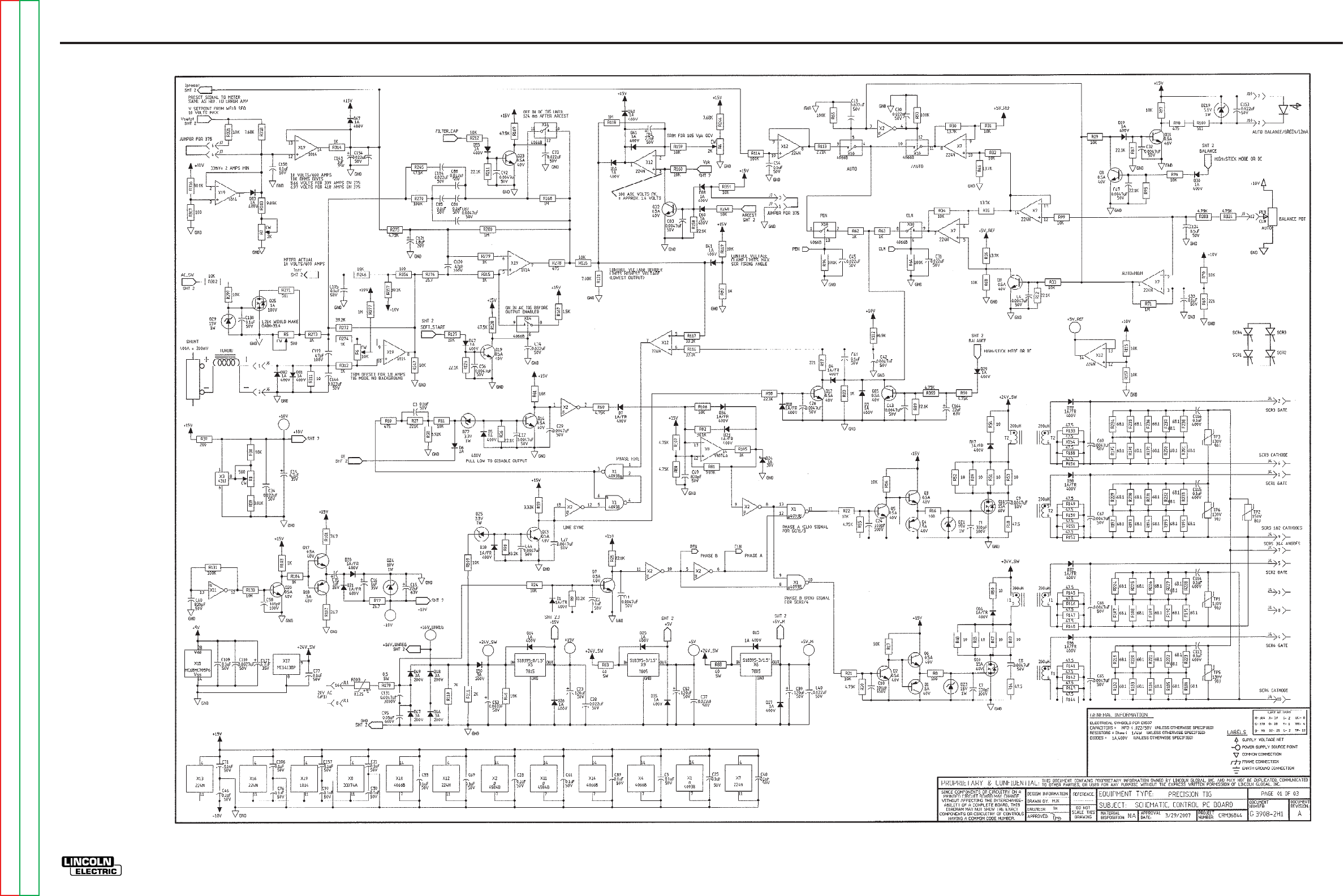
ELECTRICAL DIAGRAMS G-9
PRECISION TIG 275
®®
SCHEMATIC - CONTROL PC BOARD - BELOW CODE 11000 (G3908 PAGE 1)
G-9
NOTE: This diagram is for reference only. It may not be accurate for all machines covered by this manual.
Return to Section TOC Return to Section TOC Return to Section TOC Return to Section TOC
Return to Master TOC Return to Master TOC Return to Master TOC Return to Master TOC
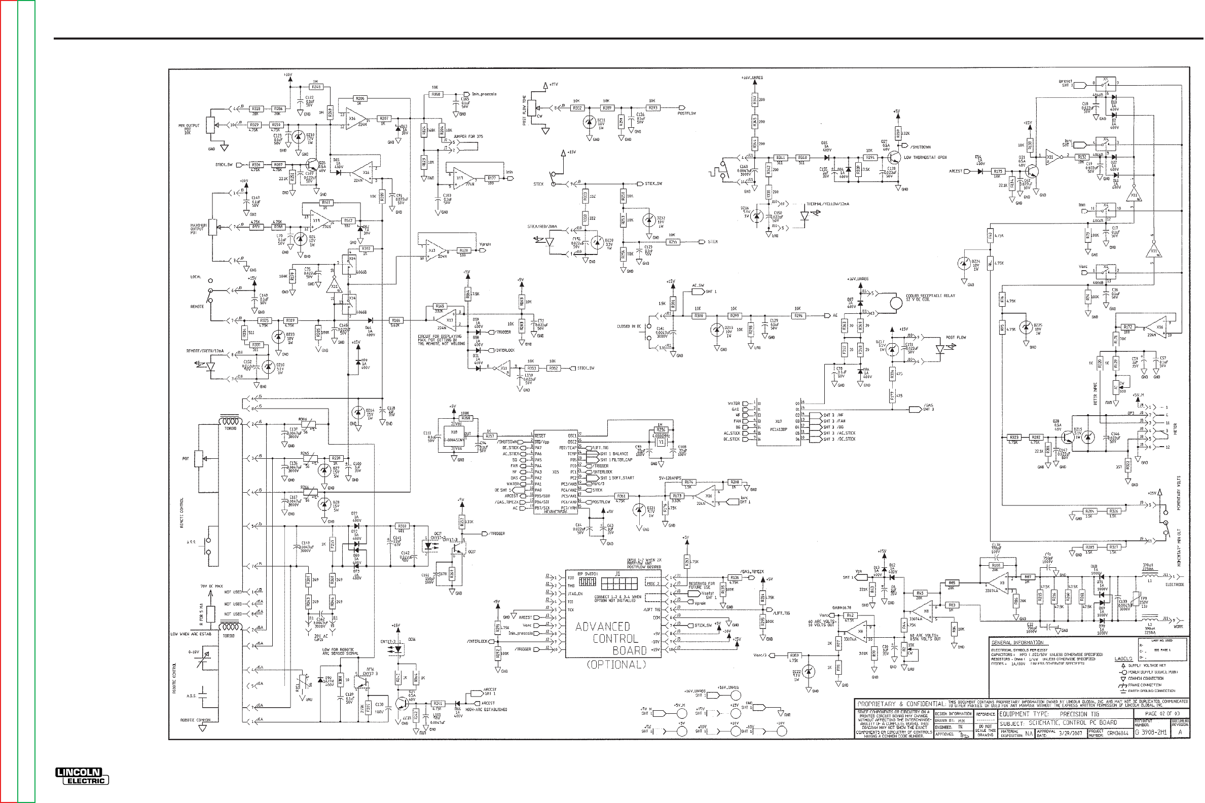
ELECTRICAL DIAGRAMS G-10
PRECISION TIG 275
®®
SCHEMATIC - CONTROL PC BOARD - BELOW CODE 11000 (G3908 PAGE 2)
G-10
NOTE: This diagram is for reference only. It may not be accurate for all machines covered by this manual.
Return to Section TOC Return to Section TOC Return to Section TOC Return to Section TOC
Return to Master TOC Return to Master TOC Return to Master TOC Return to Master TOC
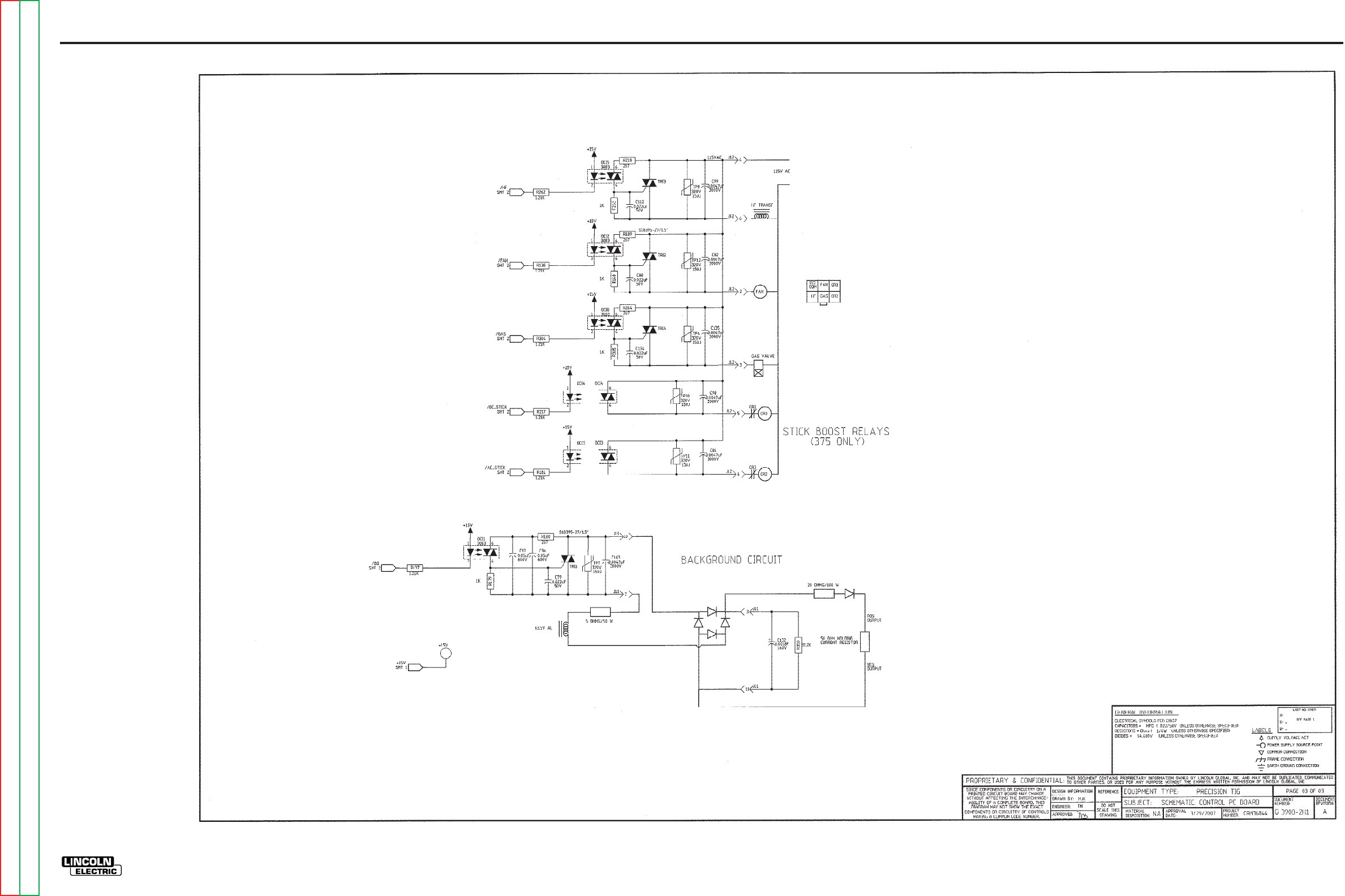
ELECTRICAL DIAGRAMS G-11
PRECISION TIG 275
®®
SCHEMATIC - CONTROL PC BOARD - BELOW CODE 11000 (G3908 PAGE 3)
G-11
NOTE: This diagram is for reference only. It may not be accurate for all machines covered by this manual.
Return to Section TOC Return to Section TOC Return to Section TOC Return to Section TOC
Return to Master TOC Return to Master TOC Return to Master TOC Return to Master TOC
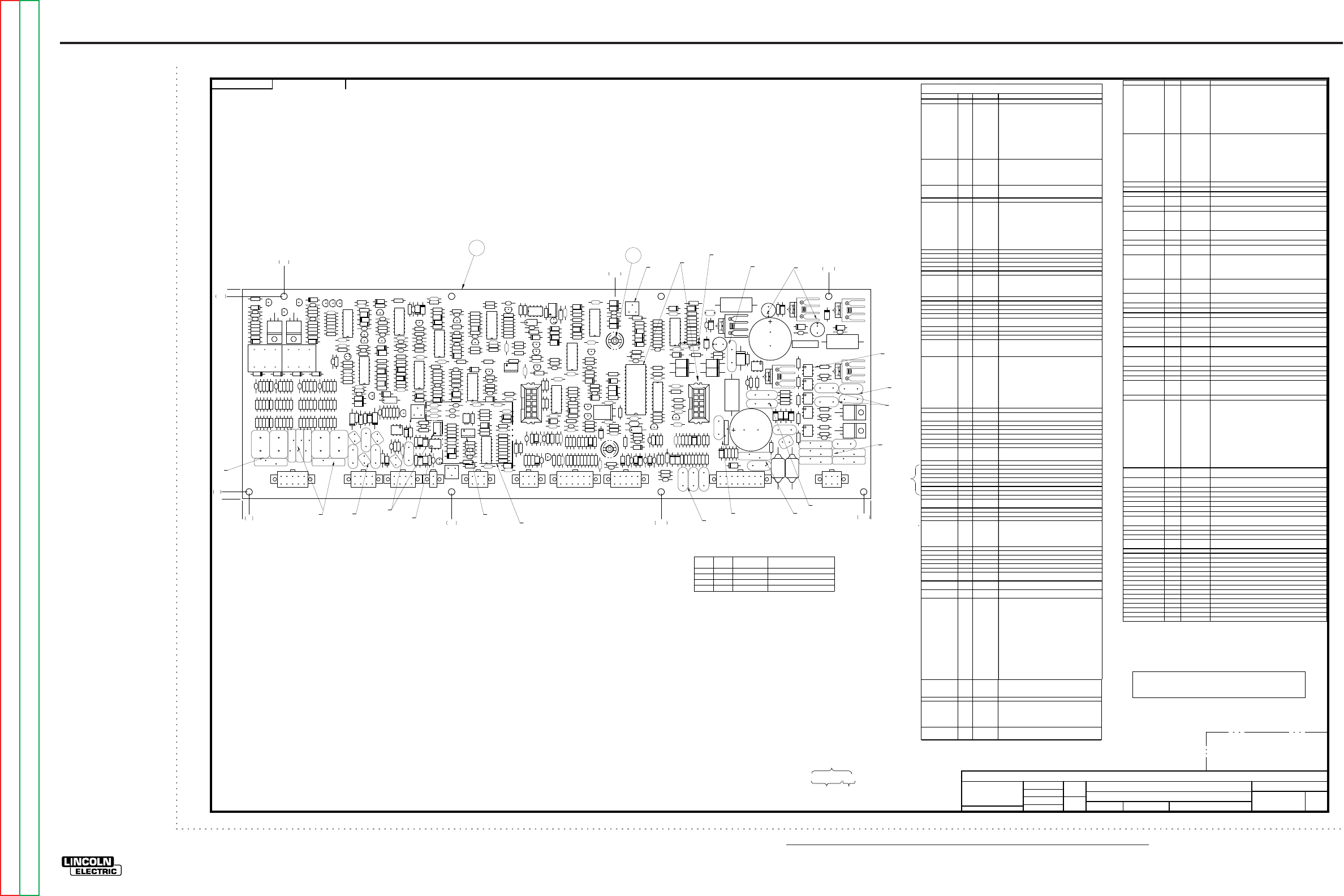
NOTE: Lincoln Electric assumes no responsibility for liablilities resulting from board level troubleshooting. PC Board repairs will invalidate your factory warranty. Individual Printed Circuit Board Components are not available from Lincoln Electric. This information is pro-
vided for reference only. Lincoln Electric discourages board level troubleshooting and repair since it may compromise the quality of the design and may result in danger to the Machine Operator or Technician. Improper PC board repairs could result in damage to the
machine.
ELECTRICAL DIAGRAMS G-12
PRECISION TIG 275
®®
PC BOARD ASSEMBLY-CONTROL - BELOW CODE 11000 (G3909-2)
G3909-2
PRECISION TIG
CONTROL P.C. BOARD ASSEMBLY
1:1
G3909-1
FEI
-
UNLESS OTHERWISE SPECIFIED TOLERANCE
MANUFACTURING TOLERANCE PER E2056
ON 2 PLACE DECIMALS IS ± .02
ON 3 PLACE DECIMALS IS ± .002
ON ALL ANGLES IS ± .5 OF A DEGREE
WITH PUBLISHED STANDARDS.
MATERIAL TOLERANCE (" ") TO AGREE
t
DO NOT SCALE THIS DRAWING
DRAWN BY:
DESIGN INFORMATION
ENGINEER:
APPROVED:
REFERENCE:
EQUIPMENT TYPE:
SUBJECT:
SCALE:
G3909-2
MATERIAL
DISPOSI TION: AP PROV AL
DATE: PROJECT
NUMBER:
UF CRM36844
1
PAGE ___ OF ___
1
ENGINEERING CONTROLLED
MANUFACTURER: No
DOCUMEN T
NUMBER: DOCUMENT
REVISION:
THIS DOCUMENT CONTAINS PROPRIETARY INFORMATION OWNED BY LINCOLN GLOBAL, INC. AND MAY NOT BE DUPLICATED, COMMUNICATED
TO OTHER PARTIES OR USED FOR ANY PURPOSE WITHOUT THE EXPRESS WRITTEN PERMISSION OF LINCOLN GLOBAL, INC.
PROPRIETARY & CONFIDENTIAL:
C
3/29/2007
ADDED C17 8 AND REVISED DZ14 PART NUMBER
REVISED MANUFACTURE AS, IDENTIFICATION CODE AND SCHEMA TICREFERENCE PART NUMBERS
ADDED SOLDER AND SEALANT NOTE FOR C178 TO ASSEMBLY
CHANGE DETAIL:
SOLID EDGE
STRP
P.C. BOARD BLANK REFERENCE INFORMATION
BUY BLANK COMPLETE AS G3909-H (4 LAYER BOARD PER E3281)
(MAKES 2 BOARDS PER PANEL, SEE ELECTRONIC FILE FOR ADDITIONAL INFORMATION)
G3 9 0 9- 2 H 1
PART NUMBER IDENTIFICATION CODE
MANUFACTURED AS:
NOTES:
N.A. CAUTION: THIS DEVICE IS SUBJ ECT TO DAMAGE BY STATIC ELECTRICITY. SEE E2454
BEFORE HANDLING.
N.B. KEEP THIS AREA FREE OF ENCAPSULATION MATERIAL (.50 MIN.) BOTH SIDES OF
BOARD.
N.C. SQUEEZE COMPONENTS TOGETHER B EFORE APPLYING ITEM 2 AND / OR
ENCAPSULATION MATERIAL.
N.D. APPLY ITEM 2 ON COMPONENT SIDE ONLY, AS SHOWN.
N.E. APPLY ITEM 2 ON B OTH SIDES OF B OARD AS SHOWN, EXCEPT TOP SURFACE OF
TRI MMER.
N.F. KEEP TOP SURFACE OF TRIMMER FREE OF ENCAPSULATION MATERIAL INCLUDING RTV.
ENCAPSULATE WITH E1844
MAKE PER E1911-ROHS
TEST PER E3937-C
SCHEMATIC REFERENCE G39 0 8-2 H1
UNLESS OTHERWISE SPECIFIED:
CAPACITANCE = MFD/ VOLTS
INDUCTANCE = HENRIES
RESISTANCE = OHMS
ITEM
1
2
REQD PART NO. DESCRIP T ION
P.C. BOARD BLANK REF.
SEE BLANK INFO.
1E2861 SEALANT
5 OZ.
3
3S19300-7 PCB SUPPORT
2
N.F.
N.A.
N.A.
N.A.
N.A.
N.A.
N.A.
N.A.
N.C.
X
X
X
N.C., N.D.
XXXX
N.C., N.D.
X
X
X
X
N.C., N.D.
X
X
X
X
X
X
X
X
X
XX
X
X
X
X
X
X
X
X
X
X
X
XXX XXX
N.D.
N.D.
N.B.
X
X
X
X
X
X
X
X
X
X
X
X
X
X
N.D.
N.E .
N.D.
XXX
XXX
XXXX
X
XXXXXXXXX
XXXX
X
X
X
X
XX
X
X
X
N.D.
N.D.
1
N.D. N.F.
N.C.
N.C.
XXXX
N.D.
N.C., N.D.
XXXXXX
X X X X X X X X X X X X X X X X XX XX XX XXX X X
X X X
X X X X X X X
X X X X X X
X X
X X X X X X
X X
X X
X X
X X
X X
XX XXXXXXX
X
X
X
X
X
X
X
X
X
X
X X
X
X
X
X
X
X
X
X
X
X
X X
X X
0.20 6.00 12.00 17.80
1.20
10.68 16.80
N.F.
N.F.
FOR PARTS ORDERS:
INCLUDE (1) S25597PRINT PARTS ORDERS
INSTRUCTION SHEE T.
J3
C27
R359
C21
R127
D59
R105
R223
R329
R212
R8
R49
X13
D49
DZ11
D10
R199
R79
R300
C115
TRI4
R30
D41
C144
R254
R343
C134
Q7
R354
R316
R303
R338
R140
C68
R42
R91
R190
R272
R187
X14
R326
D30
R151
R157
R266
D28
Q21
R324
Q15
R27
R136
X1
R5
Q28
D12
DZ23
R211
C133
DZ13
C92
R278
D7
C61
Q8
DZ21
D88
D51
L2
R31
DZ6
R130
C143
R68
R305
C58
R328
R288
C154
R280
C91
C38
R238
C72
R115
R66
R215
X2
R124
C22
R264
R132
R219
R114
R273
R23
R97
C116
C25
D64
R144
R25
R297
C40
R108
DZ24
R135
R37
R222
C86
R129
R286
R55
X19
DZ1
R77
R296
R218
R180
X6
D42
R202
D20
Q26
R53
C16
TP10
C126
D27
C75
C113
R206
C55
R86
R118
C83
R351
R302
R141
C33
TP1
R258
R103
X12
C100
R227
C46
X3
C60 C62
R339
C97
R33
C5
C149
R43
C77
R80
C102
C120
R240
R40
R170
R45
R158
C160
R312
D54C74
C41
L1
C84
R123
R29
C164
R145
C156
R63
R268
C98
C28
D84
C37
R147
R88
R349
C7
R225
C117
Q3
R99
R35 R73
DZ5
R236
Q24
C159
R291
R306
R287
D83
R4
R327
R283
C147
Q20
C53
R70
R271
R261
R101
R156
C123
R133
R155
R21
DZ2
R74
R277
R265
D36
C73
R67
C63
R234
C48
R52
R196
C111
X15
R131
C44
R104
R313
D24
R362
C13
D26
D5
C78
R208
R62
Q5
R164
R169
D18
C114
C32 R81
R11
C125
R241
R109
C141
TP9
C29
R9
R262
R110
C89
DZ4
R143
C142
R301
R139
R310
R117
R244
D55
R289
R361
D29
R59
C132
C145
TP11
TRI2
R276
C118
R15
C119
Q2
DZ9
R72
R253
Q12
R138
C121
R85
R113
OCI2
R270
R357
R336
R290
R193
DZ7
Q6
D14
R309
D46
C24
R347
R111
C122
R163
R220
R58
D63
D87
C148
C165
Q19
C94
R36
R332
R64
C158
TP8
C51
R179
R281
D72
R285
R46
C3
R47
R356
R250
R251
C43
R154
R200
R153
D35
R299
D61
C1
DZ12
R26
R120
C69
C108
R125
C109
R69
D68
R100
C150
C96
C18
R217
Q18
R48
C80
R348
D86
R7
R259
R39
DZ25
D40
DZ8
R159 R167
C54
D2
R183
R255
OCI6
X5
R171
R192
C56
C36
DZ17
J10
R224
J12
R322
J5
R221
R119
R83
R298
DZ20
D89
R174
D39
R353
R28
Q25
D60
DZ3
R84
C64
C50
D17
Q27
R204
R22
D71
R32
R98
C151
J2
D81
C85
D69
R18
R57
R19
R352
R197
R275
R232
R149
C139
X17
R112
R209
R248
C153
J7
R210
X4
R245
D82
TP3
C161
J5A
D11
D85
R304
C49
D70
C110
R12
C101
R358
R364
D79
R54
C103
R284
C26
R335
R146
R314
R235
R188
R337
C107
TP2
R330
R325
R256
R195
R334
R82
R137
T1
R321
C70
R148
C88
D15
R152
Q22
R17
R122
X8
R75R61
R24
TP4
C140
D3
R162
R252
X7
C93
R344
R317
C127
R267
R342
R307
R71
DZ19
OCI3
R94
R172
C12
R249
C95
X9
R173
R311
R182
R177
C15
C90
R341
R13
C11
D90
R243
D1
C65
C57
R323
R345
R233
TRI3
R6
DZ18
J9
R60
R293
R51
D48
R239
R350
D34
R308
R363
Q4
R41
R263
R76
R184
R294
R87
Q13
T2
C39
D31
R198
D73
D6
J8
C137
R194
C99
R65
R295
C79
R260
TP12
R292
R228
C20
R78
R315
DZ14
OCI7
C23
R185
C2
R320
C52
R247
OCI8
R95
C66
R126
D50
C10
R355
R176
R50
C81
R121
R10
R107
R229
R89
Q16
C67
R269
C104
OCI1
C30
R128
C146
R165
R168
R246
R14
R237
R175
J11
D19 D22
R106
C135
C8
D13
Q9
D62
R2
C131
R181
R346
C17
R34
R203
J6
Q1
DZ15
TRI1
R3
R166
R226
R92
C157
R116
C138
R142
R213
R257
C71
DZ10
R201
R186
D37
TP7
R1
R44
R160
TP5
C105
D38
R279
D47
R207
C129
R38
Y1
J4
C4
R282
D23
C124
C14
Q11
R102
C42
R319
R230
X16
C130
R161
C162
C87
C59
Q10
C45
C19
C34
R150
C6
C9
R205
X18
C136
R191
X10
R134
R20
D4
R242
C155
D67
R231
R340
DZ22
R331
C76
R333
R318
D66
C163
C152
C128
R96
R16
C31
Q14
C112
OCI4
Q23
D80
Q17
R90
C35
OCI5
C106
R178
D65
R214
X11
C82
D25
TP6
D16
D21
R189
R56
R93
D58
R216
R274
C47
DZ16
G3909-2
PRECISION TIG CONTROL
C178
0
.20
5.80
6.00
18.00
REFERENCES QTY PART NUMBER DESCRIPTION
C1, C7, C178 3 S16668-8 CAPACITOR,CEMO,330pF,100V,5%
C2, C3, C5, C17, C21,
C25, C28, C33, C36,
C41, C46, C48, C50,
C54, C55, C57, C61,
C69, C70, C71, C76,
C77, C78, C85, C86,
C89, C90, C94, C103,
C105, C106, C109,
C111, C122, C123,
C124, C125, C126,
C129, C130, C139,
C148, C149, C157,
C158, C165
46 S16668-11 CAPACITOR,CEMO,0.1, 50V,10%
C4, C8, C9, C11, C12,
C26, C27, C29, C32,
C42, C43, C44, C47,
C56, C65, C66, C67,
C68, C83, C87, C92,
C101
22 S16668-6 CAPACITOR,CEMO,4700pF,50V,10%
C6, C16, C20, C35,
C59, C63, C100, C118,
C143, C155
10 S13490-42 CAPACITOR,TAEL,1.0,35V,10%
C10, C24, C58 3 S16668-3 CAPACITOR,CEMO,100pF, 100V,5%
C13, C18, C19, C30,
C31, C34, C37, C38,
C40, C45, C62, C64,
C72, C73, C74, C75,
C79, C80, C88, C91,
C104, C107, C112,
C128, C134, C142,
C144, C145, C146,
C147, C150, C151,
C152, C153, C154,
C156, C159
37 S16668-5 CAPACITOR,CEMO,.022,50V,20%
C14, C127 2 S13490-25 CAPACITOR,TAEL,4.7,35V 10%
C15, C141, C164 3 S13490-181 CAPACITOR,ALEL,22,63V,20%
C22, C51 2 T11577-54 CAPACITOR,CD,750PF,1000V,10%
C23, C39, C52 3 S13490-183 CAPACITOR,ALEL,120MF,50V,20%
C49, C60 2 S16668-7 CAPACITOR,CEMO,820pF,50V,5%
C53 1 S13490-92 CAPACITOR,ALEL,3300, 50V,+30/-10%
C81, C82, C98, C99,
C117, C131, C133,
C135, C136, C137,
C140, C160, C161,
C162, C163
15 T11577-58K CAPACITOR,CD,.0047,3000V,20%
C84 1 S13490-40 CAPACITOR,TAEL,2.7,50V,10%
C93, C108 2 S16668-1 CAPACITOR,CEMO,22pF, 100V,5%
C95, C96, C97 3 T11577-46K CAPACITOR,CD,.05,600V,+80/-20%
C102, C138 2 S16668-9 CAPACITOR,CEMO,150pF, 100V,5%
C110 1 S16668-4 CAPACITOR,CEMO, 2700pF, 50V,5%
C113, C114, C115,
C116 4 S13490-81 CAPACITOR,PEF,0.1MF,400V,10%,RADIAL
C119, C120 2 S16668-2 CAPACITOR,CEMO,47pF, 100V,5%
C121 1 S13490-19 CAPACITOR,TAEL,1.8,20V,10%
C132 1 S13490-186 CAPACITOR,ALEL,1800,160V,20%
D1, D4, D7, D16, D17,
D18, D20, D21, D23,
D28, D34, D36, D37,
D38, D39, D90
16 T12705-34 DIODE,AXLDS,1A,400V,FR,1N4936
D2, D3, D5, D6, D10,
D11, D12, D13, D14,
D15, D19, D22, D25,
D26, D27, D29, D30,
D31, D35, D40, D41,
D42, D51, D54, D55,
D58, D59, D60, D61,
D64, D65, D66, D67,
D72, D73, D79, D80,
D81, D82, D83, D84,
D85, D86, D87, D88,
D89
46 T12199-1 DIODE,AXLDS,1A,400V
D24, D62, D63 3 T12705-23 DIODE,SCHOTTKY,AXLDS,1A,30V,1N5818
D46, D47, D48, D49,
D50 5 T12705-14 DIODE,AXLDS,3A,200V,1N5402
D68, D69, D70, D71 4 T12199-2 DIODE,AXLDS,1A,1000V
DZ1, DZ3, DZ9, DZ14 4 T12702-29 ZENER DIODE,1W,15V,5%,1N4744A
DZ2, DZ5, DZ20 3 T12702-53 ZENER DIODE,1W,3.3V,5%,1N4728A
DZ4, DZ11, DZ12, DZ13 4 T12702-27 ZENER DIODE,1W ,10V,5%,1N4740A
DZ6, DZ10 2 T12702-19 ZENER DIODE,1W,12V,5%,1N4742A
DZ7, DZ8 2 T12702-23 ZENER DIODE,5W,15V,5%,1N5352B
DZ15, DZ16, DZ17,
DZ18, DZ19, DZ21,
DZ22
7 T12702-52 ZENER DIODE,1W,5.1V,5%,1N4733A
DZ23, DZ24, DZ25 3 T12702-45 ZENER DIODE,1W,18V,5%,1N4746A
J2, J3 2 S21134-10 CONNECTOR,MOLEX,MINI,BLIND,F,10-PIN
J4, J10 2 S24020-10 CONNECTOR,MOLEX,MINI,PCB,10-PIN,TIN
J5, J5A 2 S24020-8 CONNECTOR,MOLEX,MINI,PCB,8-PIN,TIN
J6 1 S24020-2G CONNECTOR,MOLEX,MINI,PCB,2-PIN,GOLD
J7, J8, J12 3 S24020-6 CONNECTOR,MOLEX,MINI,PCB,6-PIN,TIN
J9 1 S24020-12 CONNECTOR,MOLEX,MINI,PCB,12-PIN,TIN
J11 1 S24020-16 CONNECTOR,MOLEX,MINI,PCB,16-PIN,TIN
L1, L2 2 T12218-9 CHOKE,RF,390UH,5%, 225MA,CONFORMAL
OCI1, OCI2, OCI5, OCI8 4 S15000-16 OPTOCOUPLER,TRIAC,DRIVER,ZVC,3083
OCI3, OCI4 2 S15000-31 OPTOCOUPLER,TRIAC,DRV,RANDOM,800V
OCI6, OCI7 2 S15000-10 OPTOCOUPLER,PHOTO-Q,70V,CNY17-3
Q1, Q4, Q18 3 T12704-69 TRANSISTOR,PNP,TO226,0.5A, 40V,2N4403
Q2, Q3, Q5, Q6, Q7,
Q8, Q9, Q12, Q13,
Q14, Q15, Q16, Q17,
Q19, Q20, Q21, Q22,
Q23, Q24, Q26, Q27,
Q28
22 T12704-68 TRANSISTOR,NPN,TO226,0.5A,40V,2N4401
Q10, Q11 2 T12704-54 TRANSISTOR,NMF,TO220,15A,60V,(SS)
Q25 1 T12704-73 TRANSISTOR,NMF,4-PIN DIP,1A,100V,IRFD110(SS)
R1, R3, R5 3 S16296-3 TRIMMER,MT,1/2W,500, 10%,LINEAR
R2 1 T10812-41 TRIMMER,ST,1/2W,10K, 10%,LINEAR
R4, R7 2 T10812-73 TRIMMER,ST,1/2W ,2K, 10%,LINEAR
R6 1 S16296-5 TRIMMER,MT,1/2W,10K, 10%,LINEAR
R8, R16, R120, R122,
R172, R317, R356 7 S19400-1000 RESISTOR,MF,1/4W,100,1%
R9, R91, R116, R117,
R350 5S19400-3322 RESISTOR,MF,1/4W,33.2K,1%
R10, R98, R177, R278,
R336 5S19400-4750 RESISTOR,MF,1/4W,475,1%
R11, R17, R21, R22,
R24, R29, R31, R32,
R33, R34, R38, R46,
R56, R61, R68, R70,
R84, R96, R97, R99,
R106, R109, R115,
R119, R123, R126,
R127, R130, R132,
R133, R157, R159,
R160, R163, R175,
R203, R204, R209,
R212, R240, R246,
R247, R250, R253,
R254, R255, R289,
R290, R293, R294,
R296, R297, R298,
R299, R300, R302,
R321, R332, R352,
R353, R354, R358
62 S19400-1002 RESISTOR,MF,1/4W,10.0K,1%
REFER TO ELECTRONIC COMPONENT DATABASE FOR SPECIFICATIONS ON ITEMS LISTED BELOW
R12, R25, R26, R58,
R67, R89, R95, R125,
R134, R158, R211,
R242, R251, R281
14 S19400-2212 RESISTOR,MF,1/4W,22.1K,1%
R13, R88 2 T14648-4 RESISTOR,WW,5W,40,5%,SQ
R14, R18, R141, R142,
R143, R144, R145,
R146, R147, R148,
R149, R150, R151,
R152, R153, R154,
R155, R156
18 S19400-47R5 RESISTOR,MF,1/4W,47.5,1%
R15, R19, R47, R48,
R49, R50, R51, R52,
R53, R54, R308, R311
12 S19400-10R0 RESISTOR,MF,1/4W,10.0,1%
ITEM REQ'D PART NO. DESCRIPTION
R20, R40, R41, R44,
R55, R60, R75, R76,
R80, R90, R107, R136,
R176, R210, R213,
R214, R241, R275,
R282, R283, R287,
R288, R291, R319,
R323, R324, R325,
R329, R330, R331,
R355, R359, R361
33 S19400-4751 RESISTOR,MF,1/4W,4.75K,1%
R23, R62, R63, R78,
R92, R103, R104,
R105, R129, R140,
R161, R179, R202,
R206, R207, R208,
R239, R243, R257,
R263, R267, R273,
R274, R279, R305,
R312, R314, R315,
R320, R364
30 S19400-1001 RESISTOR,MF,1/4W,1.00K,1%
R27, R43 2 S19400-2213 RESISTOR,MF,1/4W,221K,1%
R28 1 S19400-3921 RESISTOR,MF,1/4W,3.92K,1%
R30, R35, R36, R66 4 S19400-1372 RESISTOR,MF,1/4W,13.7K,1%
R37, R335, R342,
R344, R345, R347 6 S19400-2000 RESISTOR,MF,1/4W,200,1%
R39, R79 2 S19400-3011 RESISTOR,MF,1/4W,3.01K,1%
R42, R128, R164,
R169, R215, R216,
R245, R260, R261,
R339
10 S19400-4752 RESISTOR,MF,1/4W,47.5K ,1%
R45, R85, R86, R108,
R171 5 S19400-2002 RESISTOR,MF,1/4W,20.0K,1%
R57, R69 2 S19400-2210 RESISTOR,MF,1/4W,221,1%
R59, R173, R252, R259 4 S19400-3321 RESISTOR,MF,1/4W,3.32K,1%
R64, R65, R73, R74,
R93, R94, R114, R131,
R135, R170, R205,
R258, R270, R292,
R295
15 S19400-1003 RESISTOR,MF,1/4W,100K,1%
R71, R83, R87, R118,
R168, R248, R249,
R256, R277, R280
10 S19400-1004 RESISTOR,MF,1/4W,1.00M,1%
R72, R101, R102, R276 4 S19400-26R7 RESISTOR,MF,1/4W,26.7,1%
R77, R110, R111 3 S19400-2001 RESISTOR,MF,1/4W,2.00K,1%
R81, R313 2 S19400-9091 RESISTOR,MF,1/4W,9.09K,1%
R82, R316, R357 3 S19400-3012 RESISTOR,MF,1/4W,30.1K,1%
R100, R271, R334,
R337, R340, R341 6 S19400-5110 RESISTOR,MF,1/4W,511,1%
R112 1 S19400-9092 RESISTOR,MF,1/4W,90.9K,1%
R113 1 S19400-2211 RESISTOR,MF,1/4W,2.21K,1%
R121, R124, R244,
R318 4 S19400-7681 RESISTOR,MF,1/4W,7.68K,1%
R137, R138, R181,
R217, R262, R304 6 S19400-1211 RESISTOR,MF,1/4W,1.21K,1%
R139, R180, R218,
R264 4S19400-2670 RESISTOR,MF,1/4W,267,1%
R162, R333, R338 3 S19400-3320 RESISTOR,MF,1/4W,332,1%
R165 1 S19400-3323 RESISTOR,MF,1/4W,332K,1%
R166 1 S19400-5621 RESISTOR,MF,1/4W,5.62K,1%
R167, R174, R284,
R285, R301, R326,
R327
7 S19400-1501 RESISTOR,MF,1/4W,1.50K,1%
R178 1 T14648-24 RESISTOR,WW,5W ,0.5,5%,SQ
R182, R183, R184,
R185, R186, R187,
R188, R189, R190,
R191, R192, R193,
R194, R195, R196,
R197, R198, R199,
R200, R201, R219,
R220, R221, R222,
R223, R224, R225,
R226, R227, R228,
R229, R230, R231,
R232, R233, R234,
R235, R236, R237,
R238
40 S19400-68R1 RESISTOR,MF,1/4W,68.1,1%
R265, R266, R306,
R351 4 S18380-1 THERMISTOR,PTC,56 OHMS,90MA
R268, R309, R343,
R346 4S19400-2490 RESISTOR,MF,1/4W,249,1%
R269, R307 2 S19400-2673 RESISTOR,MF,1/4W,267K,1%
R272 1 S19400-3922 RESISTOR,MF,1/4W,39.2K,1%
R286, R328 2 S19400-2802 RESISTOR,MF,1/4W,28.0K,1%
R303 1 S18380-3 THERMISTOR,PTC,.08-0.19 OHMS,1.85A
R310 1 S19400-6810 RESISTOR,MF,1/4W,681,1%
R322 1 S19400-3570 RESISTOR,MF,1/4W,357,1%
R348, R349, R362,
R363 4S19400-20R0 RESISTOR,MF,1/4W,20.0,1%
T1, T2 2 T12737-2 TRANSFORMER,PULSE,3-WINDING,1:1:1
TP1, TP3, TP5, TP6 4 T13640-25 MOV,130VRMS,90J,20MM
TP2 1T13640-16 MOV,150VRMS,80J,20MM
TP8 1 T13640-14 MOV,150VRMS,13J,7MM
TRI1, TRI2 2 S18395-27 TRIAC,T220,8A,800V WITH S18104-3HS
TRI3, TRI4 2 S15161-27 TRIAC,T220,8A,800V
X1 1 S15018-15 IC,CMOS,GATE,NAND,2-INPUT,QUAD,SCHM(SS)
X2, X11 2 S15018-4 IC,CMOS,INVERTER,SCHMITT, HEX,4584(SS)
X3 1S15128-10 VOLTAGE REF,ADJ, PRECISION,431I
X4, X10, X14 3 S15018-6 IC,CMOS,SWITCH,ANALOG,QUAD, 4066(SS)
X5 1 S18395-8 REGULATOR,HEAT-SINKASBLY,S15128-6,S18104-3
X6, X9 2 S18395-3 REGULATOR,HEAT-SINKASBLY,S15128-5,S18104-3
X7, X12, X13, X16 4 S15128-4 OP-AMP,QUAD, GEN-PURPOSE,224N
X8 1 S15128-18 OP-AMP,QUAD, HIGH-PERF,33074
X15 1 S25431-2 ROM ASSEMBLY (SS)
X17 1 M15102-4 IC,ARRAY,DRIVER,PERIPHERAL,NPN,DARL
X18 1M15102-3 IC,CMOS,UNDERVOLT-SENSING,RESET,MCU(SS)
X19 1 S15128-16 IC,OP-AMP,QUAD,HIGH-PERF,1014
Y1 1 S16665-2 CRYSTAL,QUARTZ,4.0000MHZ,HC-18/U
TP4, TP7, TP9, TP10,
TP11, TP12 6T13640-18 MOV,320VRMS,150J,20MM
ALL COMPONENTS AND MATERIALS USED IN THIS
ASSEMBLY ARE TO BE RoHS COMPLIANT PER E4253.
SOLDER CAPACITOR (C178) TO R108AS SHOWN.
COVER WITH E2861 SEALANT.
G-12
Return to Section TOC Return to Section TOC Return to Section TOC Return to Section TOC
Return to Master TOC Return to Master TOC Return to Master TOC Return to Master TOC
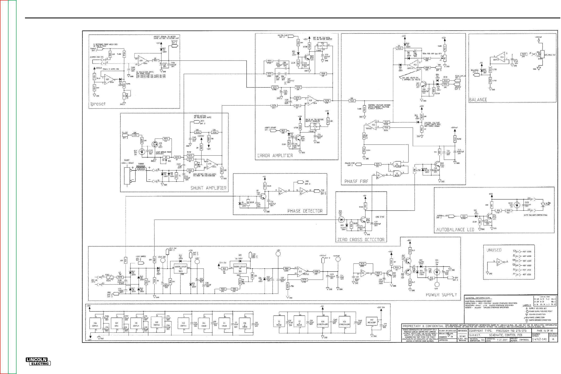
ELECTRICAL DIAGRAMS G-13
PRECISION TIG 275
®®
SCHEMATIC - CONTROL PC BOARD - ABOVE CODE 11000 (G4762 PAGE 1)
G-13
NOTE: This diagram is for reference only. It may not be accurate for all machines covered by this manual.
Return to Section TOC Return to Section TOC Return to Section TOC Return to Section TOC
Return to Master TOC Return to Master TOC Return to Master TOC Return to Master TOC
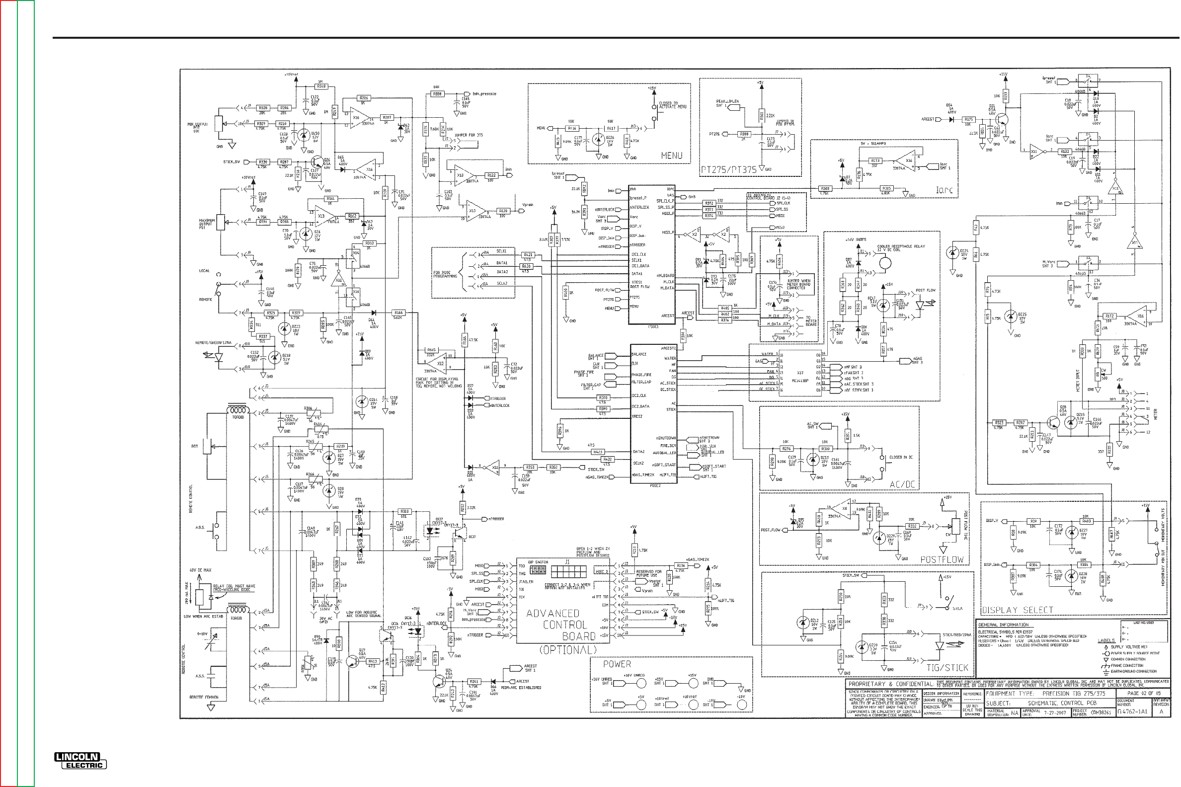
ELECTRICAL DIAGRAMS G-14
PRECISION TIG 275
®®
SCHEMATIC - CONTROL PC BOARD - ABOVE CODE 11000 (G4762 PAGE 2)
G-14
NOTE: This diagram is for reference only. It may not be accurate for all machines covered by this manual.
Return to Section TOC Return to Section TOC Return to Section TOC Return to Section TOC
Return to Master TOC Return to Master TOC Return to Master TOC Return to Master TOC
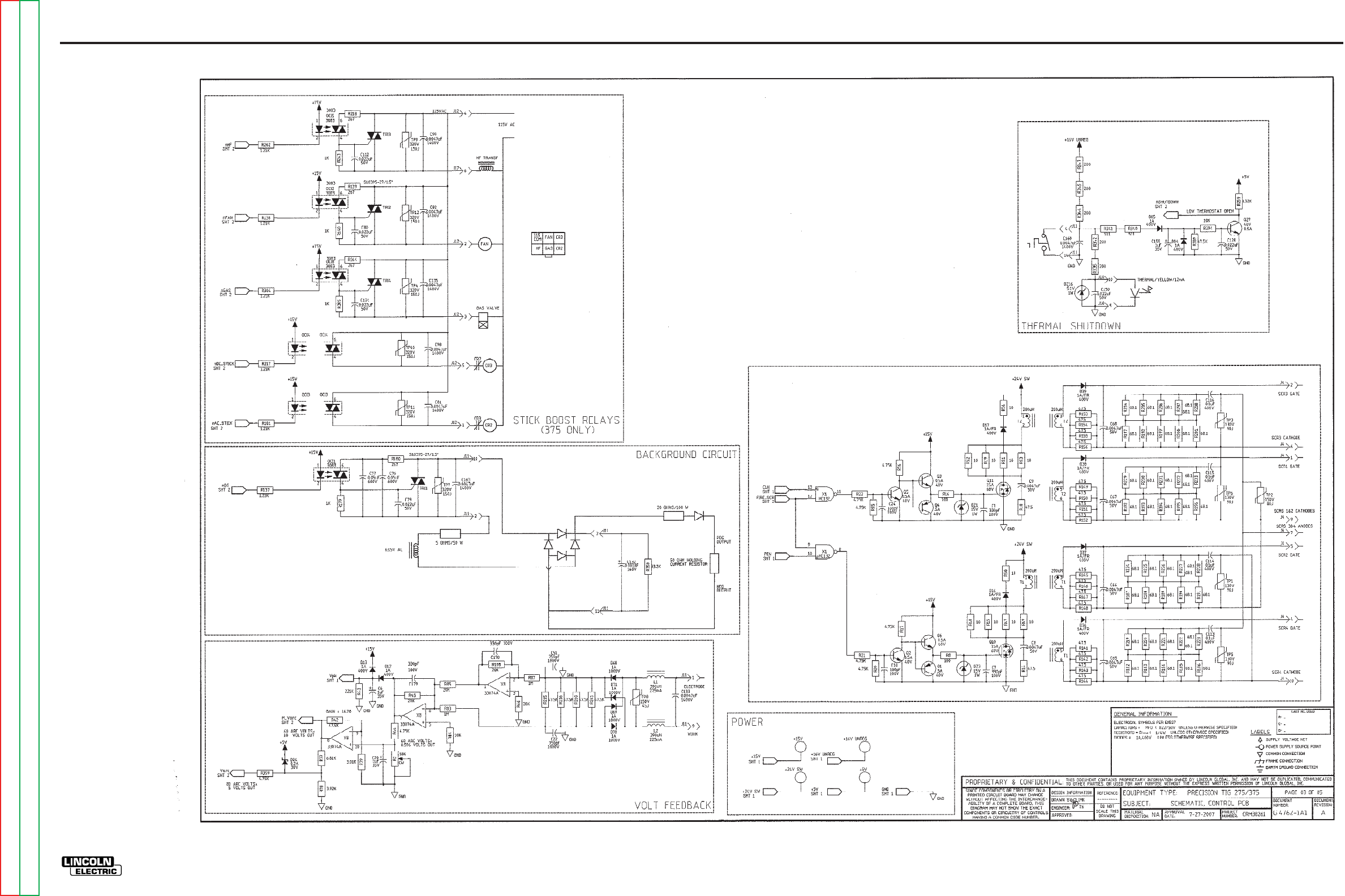
ELECTRICAL DIAGRAMS G-15
PRECISION TIG 275
®®
SCHEMATIC - CONTROL PC BOARD - ABOVE CODE 11000 (G4762 PAGE 3)
G-15
NOTE: This diagram is for reference only. It may not be accurate for all machines covered by this manual.
Return to Section TOC Return to Section TOC Return to Section TOC Return to Section TOC
Return to Master TOC Return to Master TOC Return to Master TOC Return to Master TOC
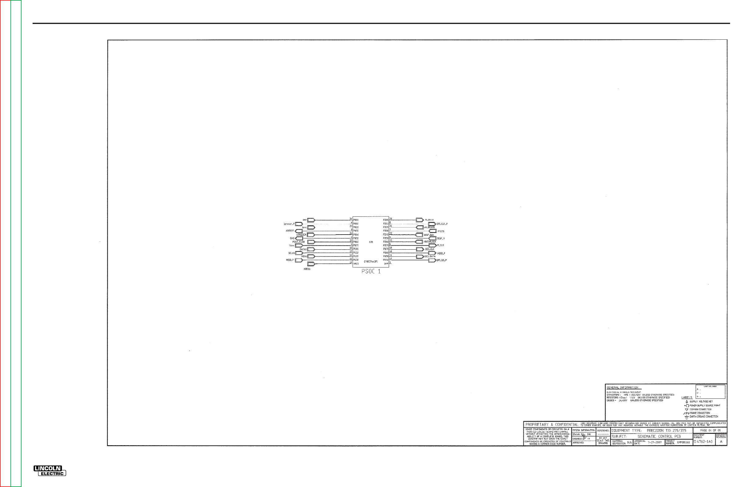
ELECTRICAL DIAGRAMS G-16
PRECISION TIG 275
®®
SCHEMATIC - CONTROL PC BOARD - ABOVE CODE 11000 (G4762 PAGE 4)
G-16
NOTE: This diagram is for reference only. It may not be accurate for all machines covered by this manual.
Return to Section TOC Return to Section TOC Return to Section TOC Return to Section TOC
Return to Master TOC Return to Master TOC Return to Master TOC Return to Master TOC
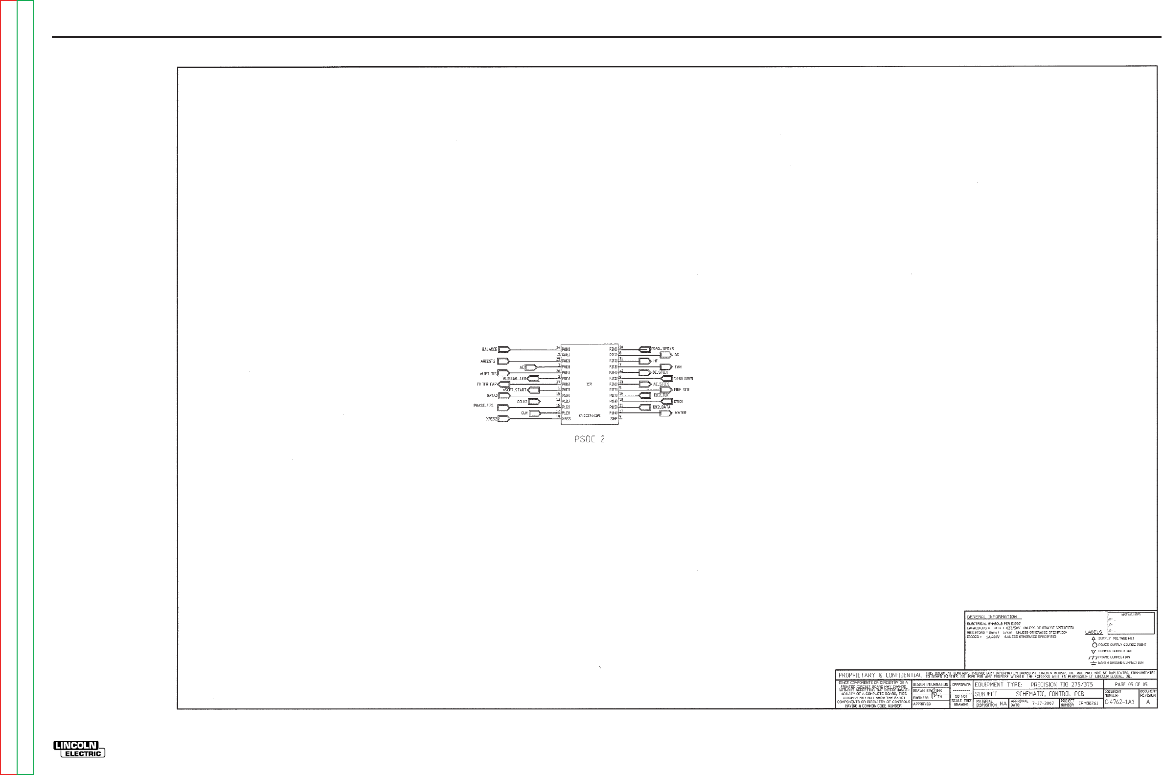
ELECTRICAL DIAGRAMS G-17
PRECISION TIG 275
®®
SCHEMATIC - CONTROL PC BOARD - ABOVE CODE 11000 (G4762 PAGE 5)
G-17
NOTE: This diagram is for reference only. It may not be accurate for all machines covered by this manual.
Return to Section TOC Return to Section TOC Return to Section TOC Return to Section TOC
Return to Master TOC Return to Master TOC Return to Master TOC Return to Master TOC
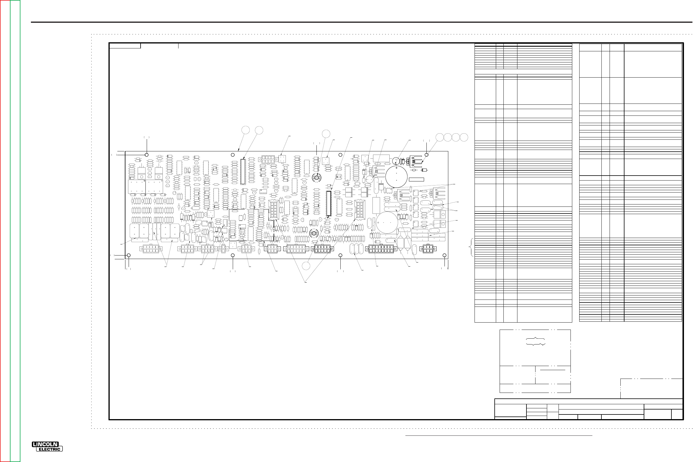
NOTE: Lincoln Electric assumes no responsibility for liablilities resulting from board level troubleshooting. PC Board repairs will invalidate your factory warranty. Individual Printed Circuit Board Components are not available from Lincoln Electric. This information is pro-
vided for reference only. Lincoln Electric discourages board level troubleshooting and repair since it may compromise the quality of the design and may result in danger to the Machine Operator or Technician. Improper PC board repairs could result in damage to the
machine.
ELECTRICAL DIAGRAMS G-18
PRECISION TIG 275
®®
PC BOARD ASSEMBLY-CONTROL - ABOVE CODE 11000 (G4763-1)
G4763-1
PRECISION TIG
CONTROL P.C. BOARD ASSEMBLY
1:1
G3909
JB
TNguyen
-
UNLESS OTHERWISE SPECIFIED TOLERANCE
MANUF ACTURING TOLERANC E PER E2056
ON 2 PLA CE DE CIMA LS IS ± .0 2
ON 3 PLACE DEC IMALS IS ± .002
ON AL L A N GLES IS ± .5 OF A DE G REE
WITH PUB LIS HE D STAN DA R DS.
MATER IAL T O LE RA NCE (" ") T O AG REE
t
DO NOT SCAL E THI S DR AWING
DRAWN BY:
DESIG N INF ORMATIO N
ENGI NEER:
APPR OVED:
REFERENCE:
EQUIPMENT TYPE:
SUBJECT:
SCA LE:
G4763-1
MATERIAL
DISPOSITION: APPROVAL
DATE: PROJECT
NUMBER:
NA CRM38261
1
PAGE ___ OF ___
1
ENGINEERING CONTROLLED
MANUFACTURER: No
DOCUMENT
NUMBER: DOCUMENT
REVISION:
THIS DOCUMEN T CON TAINS PROPRIETARY INFORMATION O WNED BY LINCOLN G LOBAL, INC. AND MA Y NOT BE DUPLICATED, COM MUNICATED
TO O THER PARTIES OR USED FOR AN Y PURPOSE WITHOU T THE EXPRESS WRIT TEN PERMISSION OF LINCOLN GL OBAL, INC.
PROPRIETARY & CONFIDENTIAL:
A
7-27-2007
RELEASED FROM X A.02
CHANGE DETAIL:
SOLID EDGE
STRP
NOTES:
N.A. CAUTION: THIS DEVICE IS SUBJECT TO DAMAGE BY STATIC ELECTRICITY. SEE E2454
BEFORE HANDLING.
N.B. KEEP THIS AREA FREE OF ENCAPSULATION MATERIAL (.50 MIN.) BOTH SIDES OF
BOARD.
N.C. SQUEEZE COMPONENTS TOGETHER BEFORE APPLYING ITEM 7 AND / OR
ENCAPSULATION MATERIAL.
N.D. APPLY ITEM 7 ON COMPONENT SIDE ONLY, AS SHOWN.
N.E. APPLY ITEM 7 ON BOTH SIDES OF BOARD AS SHOWN, EXCEPT TOP SURFACE OF
TRIMMER. MAXIMUM ITEM 7 HEIGHT NEAR CONNECTOR J2 IS .50 INCHES.
N.F. KEEP TOP SURFACE FREE OF ENCAPSULATION MATERIAL INCLUDING RTV.
N.G. PROGRAM X20 WITH ITEM 8 AND LABEL X20 WITH PART NO. OF ITEM 8.
N.H. PROGRAM X21 WITH ITEM 9 AND LABEL X21 WITH PART NO. OF ITEM 9.
N.J. COVER WITH TAPE AFTER PROGRAMMING.
N.K. APPLY ITEM 7 ON COMPONENT SIDE ONLY, AS SHOWN. MAXIMUM ITEM 7 HEIGHT IS .50
INCHES.
N.L. APPLY ITEM 7 TO CONNECTOR’S PLASTIC MOUNTING PINS ON NON-COMPONENT SIDE.
UNLESS OTHERWISE SPECIFIED:
CAPACITANCE = MFD/VOLTS
INDUCTANCE = HENRIES
RESISTANCE = OHMS
6
N.F.
N.A.
N.A.
N.A.
N.A.
N.A.
N.A.
N.A.
N.C.
X
X
X
N.C., N.D.
XXXX
N.C., N.D.
X
X
X
X
N.C., N.D.
X
X
X
X
X
X
X
X
X
XX
X
X
X
X
X
X
X
X
X
X
X
XXX
N.D.
N.D.
N.B.
X
X
X
X
X
X
X
X
X
X
X
X
X
X
N.K.
N.E.
N.D.
XXX
XXX
XXXX
X
XXXXXXXXX
XXXX
X
X
X
X
XX
X
X
X
N.C.,N.D.
N.C.,N.D.
1
N.D. N.F.
N.C.
N.C.
XXXX
N.D.
N.C., N.D.
XXXXXX
XX X X X X XX XX XX XX XX XX XX XX XXX X X
X X X
XXX X XXX
XX X X XX
X X
XX X X XX
X X
X X
X X
XX
XX
XX XXXXXXX
X
X
X
X
X
X
X
X
X
X
XX
X
X
X
X
X
X
X
X
X
X
XX
XX
0.20 6.00 12.00 17.80
1.20
10.68 16.80
N.F.
N.F.
FOR PARTS ORDERS:
INCLUDE (1) S25597PRINT PARTS ORDERS
INSTRUCTION SHEET.
PRECISION TIG CONTROL
G4763-1
J3
R155
R377
C117
R24
R371
C142
R400
C52
D66
R331
R51
R25
Q22
R248
C46
DZ2 6
C133
R398
R147
C135
OCI8
R159
C163
X14
C106
R119
C141
Q11
R350
R177
R237
R188
R116
R297
C145
R197
C79
R282
R308
R252
R421
DZ23
R17
R179
DZ1
OCI6
R342
C124
R180
R263
DZ8
R66
R224
X4
D12
R137
Q10
X19
X11
R52
R335
DZ7
R154
R178
R356
R343
R176
R129
R59
OCI1
DZ18
D48
R101
R112
R202
R15
TP7
R253
C113
C70
R235
D71
C132
Q16
C57
R321
R216
C96
R277
C151
X5
R295
R38
R102
R173
C97
R196
C175
R172
Q24
C147
C178
R369
R368
R231
R136
C165
R131
R3
R156
C8 R372
R261
C160
D83
R311
D55
R273
R164
R328
R203
R385
D68
D95
C60
R215
X2
TRI1
R13
R362
R181
R337
R366
R222
R420
R152
R14
Q7
R367
J7
R389
R247
R194
C112
R408
R47
C6
X17
C69
R286
C123
OCI7
R104
Q18
OCI3
D62
X21
R275
R347
R305
C20
R409
C150
D40
R91
R184
R192
C24
R139
R153
R191
R294
C67
D84
C74
R227
R18
R279
R146
R57
Q12
C149
R55
R310
C92
C146
R230
C26
D64
R281
R138
R7
C130
R392
R312
R6
C2
R376
R58
C143
DZ19
R43
R239
D10
R358
C44
DZ2 7
R185
DZ6
R344
C171
R402
R141
R214
R387
R303
R103
C17
C105
R269
C88
C122
R145
C72
C53
J4
C118
R349
C1 52
D86
Q29
C121
C86
TP2
R166
R45
X13
Q23
R322
C159
D94
R381
DZ15
D87
C19
D50
R264
C155
R228
R346
R211
C153
D36
R384
R260
R46
R307
C91
R244
C37
R249
C89
R410
TP10
J12
C87
DZ2 5
R198
R317
D93
R357
R339
D65
C25
C84
R395
C104
R266
R296
C158
R341
D21
C32
DZ13
R168
R225
D69
R40
R412
DZ2 8
C156
Q2
C129
R39
TP9
R76
R270
D38
D91
R306
R213
R304
R134
R406
R333
R9
DZ20
D85
R246
D20 C16
R186
C139
TP11
R54
C99
C116
DZ14
R241
C115
C138
D79
R150
R318
C51
R92
R329
R160
R300
R338
R140
R78
Q5
C177
D37
R171
R201
R319
L1
D58
R379
D80
C78
DZ9
R373
C71
R413
TRI4
C56
D82
D19
R133
R175
R238
DZ1 7
DZ2 4
C101
R187
R49
R418
C119
J6
C144
C76
Q19
R42
R352
R209
C172
R221
D49
DZ29
R163
R382
T2
D59
R29
R259
Q17
R374
OCI4
R127
TP6
R274
R217
R265
C82
R170
C103
Q1
R364
R348
C134
Q26
C98
R111
R110
R325
J5A
C137
C42
Q28
D25
D13
J13
R183
R334
Q6
R199
D26
R236
D73
TP5
R165
D11
R122
R276
C50
R292
R313
C85
R320
R226
C102
C148
R380
D17
R21
R48
R162
D92
R189
J14
R182
D39
R416
R212
C1
D72
R336
D2
R407
C22
R77
C59
D89
C90
TP1
C140
R419
C21
C75
R200
C100
C58
R417
R405
TP4
R332
TRI3
J11
J2
T1
D7
X1
DZ4
C35
R223
R375
R280
R124
R229
DZ16
X12
DZ3
R73
D35
R323
C66
R149
TP3
D60
OCI2
R2
X20
D96
C161
R388
C128
R125
C68
R278
R289
R79
C62
D28
R4
TP12
R351
R132
C41
D42
Q3
TP8
R243
C18
R44
L2
R299
C83
R411
R404
C81
R148
D16
C169
D14
C80
R363
R309
D1
C170
R142
C73
C167
R67
D46
R117
C173
R207
C36
D67
C168
C176
D61
R386
C157
X8
C162
R291
D81
R245
R401
X9
DZ12
R41
R98
R195
R85
Q27
R378
D47
R267
C10
R143
R268
R394
R126
C154
R250
R345
D51
C131
R128
R97
R118
R50
R219
C125
R108
R53
J5
DZ1 0
R403
R240
R232
R391
J8
D22
R167
R233
R316
X16
D90
Q21
R151
C28
R100
R314
C9
R205
R130
R204
R254
R87
R56
R19 R365
R83
R423
R144
R415
R190
R293
R353
R396
R20
D63
C7
R302
DZ5
R390
R109
R422
C65
R251
R414
R234
R242
R5
R220
C179
R158
C23
R123
R330
C38
OCI5
D41
Q13
R287
C1 5
R72
C11
Q20
R361
Q4
C61
R74
D18
D54
R161
R210
C5
R272
C14
R193
R288
C120
TRI2
R298
R169
R315
J9
R206
C77
R301
R22
Q25
R340
D70
R84
R262
D31
R75
C107
R271
C136
R8
R359
C27
R16
C114
R120
R218
R383
R135
R121
C95
J10
0
.20
5.80
6.00
18.00
ALL COMPONENTS AND MATERIALS USED IN THIS
ASSEMBLY ARE TO BE RoHS COMPLIANT PER E4253
REVISION CONTROL
G4763-1A1
PART NO. IDENTIFICATION
CODE
TEST PER
COAT WITH E1844 AND E3668
SCHEMATIC REFERENCE:
MAKE DETAIL
MANUFACTURE PER E1911
BUY BLANK COMPLETE
SEE ELECTRONIC FILE FOR ADDITIONAL INFORMATION.
E4298-C
G4762-1A1
( 2 BOARDS PER PANEL)
4LAYER BOARD BLANK PANEL
ITEM QTY PART NUMBER DESCRIPTION
11 G4763-A PC BOARD BLANK
2(TRI1, TR!2, X5, X9)* 4 CF000003 6-32 X .375 ROUND HEAD MACHINE SCREW
3(TRI1, TRI2, X5, X9)* 4 E106A-13 # 6 LOCK WASHER
4(TRI1, TRI2, X5, X9)* AS REQ E1868 THERMO JOINT COMPOUND
5(TRI1, TRI2, X5, X9)* 4 S18104-3 HEAT SINK,ALUMINUM,EXTRUDED,FOR 1 TO-220
62 S19300-7 SUPPORT,PCB,SNAP=IN,063,WHT
7 5.0 OZ E2861 SEALANT
81 S26860-1 PSOC SOFTWARE
9 1 S26861-1 PSOC SOFTWARE
REFERENCES QTY PART NUMBER DESCRIPTION
C1, C7, C178, C179 4 S16668-8 CAPACITOR,CEMO,330pF,100V,5%
C2, C5, C17, C21, C25,
C28, C36, C41, C46, C50,
C57, C61, C69, C70, C71,
C76, C77, C78, C85, C86,
C89, C90, C103, C105,
C106, C122, C123, C124,
C125, C129, C130, C139,
C148, C149, C157, C158,
C165, C167, C168, C169,
C171, C172, C173, C176,
C177
45 S16668-11 CAPACITOR,CEMO,0.1, 50V,10%
C6, C16, C20, C35, C59,
C100, C118, C143, C155 9 S13490-42 CAPACITOR,TAEL,1.0,35V,10%
C8, C9, C11, C26, C27,
C32, C42, C44, C56, C65,
C66, C67, C68, C83, C87,
C92, C101
17 S16668-6 CAPACITOR,CEMO,4700pF,50V,10%
C10, C24, C58 3 S16668-3 CAPACITOR,CEMO,100pF, 100V,5%
C14, C15, C141 3 S13490-181 CAPACITOR,ALEL,22,63V,20%
C18, C19, C37, C38, C62,
C72, C73, C74, C75, C79,
C80, C88, C91, C104,
C107, C112, C128, C134,
C142, C144, C145, C146,
C147, C150, C151, C152,
C153, C154, C156, C159,
C170
31 S16668-5 CAPACITOR,CEMO,.022,50V,20%
C22, C51 2 T11577-54 CAPACITOR,CD,750PF,1000V,10%
C23, C52 2 S13490-183 CAPACITOR,ALEL,120MF,50V,20%
C53 1 S13490-92 CAPACITOR,ALEL,3300, 50V,+30/-10%
C60 1 S16668-7 CAPACITOR,CEMO,820pF,50V,5%
C81, C82, C98, C99,
C117, C131, C133, C135,
C136, C137, C140, C160,
C161, C162, C163
15 T11577-52K CAPACITOR,CD,.0047/.005,1400V,20%
C84 1 S13490-40 CAPACITOR,TAEL,2.7,50V,10%
C95, C96, C97 3 T11577-46K CAPACITOR,CD,.05,600V,+80/-20%
C102, C138 2 S16668-9 CAPACITOR,CEMO,150pF, 100V,5%
C113, C114, C115, C116 4 S13490-81 CAPACITOR,PEF,0.1MF,400V,10%,RADIAL
C119, C120 2 S16668-2 CAPACITOR,CEMO,47pF, 100V,5%
C121 1 S13490-19 CAPACITOR,TAEL,1.8,20V,10%
C132 1 S13490-186 CAPACITOR,ALEL,1800,160V,20%
C175 1 S16668-1 CAPACITOR,CEMO,22pF, 100V,5%
D1, D16, D17, D18, D20,
D21, D28, D36, D37, D38,
D39, D90 12 T12705-34 DIODE,AXLDS,1A,400V,FR,1N4936
D2, D10, D11, D12, D13,
D14, D19, D22, D25, D26,
D31, D35, D40, D41, D42,
D51, D54, D55, D58, D59,
D60, D61, D64, D65, D66,
D67, D72, D73, D79, D80,
D81, D82, D83, D84, D85,
D86, D87, D89, D96
39 T12199-1 DIODE,AXLDS,1A,400V
D7, D91, D92, D93, D94,
D95 6 T12705-64 DIODE,SCHOTTKY,AXLDS,0.2A,30V,BAT42
D46, D47, D48, D49, D50 5 T12705-14 DIODE,AXLDS,3A,200V,1N5402
D62, D63 2 T12705-23 DIODE,SCHOTTKY,AXLDS,1A,30V,1N5818
D68, D69, D70, D71 4 T12199-2 DIODE,AXLDS,1A,1000V
DZ1, DZ3, DZ9, DZ29 4 T12702-29 ZENER DIODE,1W,15V,5%,1N4744A
DZ4, DZ12, DZ13, DZ26,
DZ27, DZ28 6 T12702-27 ZENER DIODE,1W,10V,5%,1N4740A
DZ5, DZ20 2 T12702-53 ZENER DIODE,1W,3.3V,5%,1N4728A
DZ6, DZ10 2 T12702-19 ZENER DIODE,1W,12V,5%,1N4742A
DZ7, DZ8, DZ14 3 T12702-23 ZENER DIODE,5W,15V,5%,1N5352B
DZ15, DZ16, DZ17, DZ18,
DZ19 5 T12702-52 ZENER DIODE,1W,5.1V,5%,1N4733A
DZ23, DZ24, DZ25 3 T12702-45 ZENER DIODE,1W,18V,5%,1N4746A
J2, J3 2 S21134-10 CONNECTOR,MOLEX,MINI,BLIND,F,10-PIN
J4, J10 2 S24020-10 CONNECTOR,MOLEX,MINI,PCB,10-PIN,TIN
J5, J13, J5A 3 S24020-8 CONNECTOR,MOLEX,MINI,PCB,8-PIN,TIN
J6 1 S24020-2G CONNECTOR,MOLEX,MINI,PCB,2-PIN,GOLD
J7, J8, J12 3 S24020-6 CONNECTOR,MOLEX,MINI,PCB,6-PIN,TIN
J9 1 S24020-12 CONNECTOR,MOLEX,MINI,PCB,12-PIN,TIN
J11 1 S24020-16 CONNECTOR,MOLEX,MINI,PCB,16-PIN,TIN
J14 1 S18248-4 CONNECTOR,MOLEX,MINI,PCB,4-PIN
L1, L2 2 T12218-9 CHOKE,RF,390UH,5%, 225MA,CONFORMAL
OCI1, OCI2, OCI5, OCI8 4 S15000-16 OPTOCOUPLER,TRIAC,DRIVER,ZVC,3083
OCI3, OCI4 2 S15000-31 OPTOCOUPLER,TRIAC,DRV,RANDOM,800V
OCI6, OCI7 2 S15000-10 OPTOCOUPLER,PHOTO-Q,70V,CNY17-3
Q1, Q4, Q18 3 T12704-69 TRANSISTOR,PNP,TO226,0.5A, 40V,2N4403
Q2, Q3, Q5, Q6, Q7, Q12,
Q13, Q16, Q17, Q19,
Q20, Q21, Q22, Q23,
Q24, Q26, Q27, Q28, Q29
19 T12704-68 TRANSISTOR,NPN,TO226,0.5A,40V,2N4401
Q10, Q11 2 T12704-54 TRANSISTOR,NMF,TO220,15A,60V,(SS)
Q25 1 T12704-73 TRANSISTOR,NMF,4-PIN DIP,1A,100V,IRFD110(SS)
R2 1 T10812-41 TRIMMER,ST,1/2W,10K, 10%,LINEAR
R3, R5 2 S16296-3 TRIMMER,MT,1/2W,500, 10%,LINEAR
R4, R7 2 T10812-73 TRIMMER,ST,1/2W,2K, 10%,LINEAR
R6 1 S16296-5 TRIMMER,MT,1/2W,10K, 10%,LINEAR
R8, R16, R120, R122,
R172, R317, R356, R369,
R376, R380, R402 11 S19400-1000 RESISTOR,MF,1/4W ,100,1%
R9, R91, R116, R117,
R350 5 S19400-3322 RESISTOR,MF,1/4W,33.2K,1%
R13 1 T14648-4 RESISTOR,WW,5W ,40,5%,SQ
R14, R18, R141, R142,
R143, R144, R145, R146,
R147, R148, R149, R150,
R151, R152, R153, R154,
R155, R156, R390, R398,
R413, R420, R421, R422,
R423
25 S19400-47R5 RESISTOR,MF,1/4W ,47.5,1%
REFER TO ELECTRONIC COMPONENT DATABASE FOR SPECIFICATIONS ON ITEMS LISTED BELOW
X
X
X
X
X
X
X
X
X
X
X
X
X
X
XX XX
XX X X XX
XX
2 3 4 5
8N.G.
9N.H.
N.A.
N.A.
XXX
XXX
X X X X
X
N.D.
N.J.
N.K.,N.L.
N.C.
R15, R19, R47, R48, R49,
R50, R51, R52, R53, R54,
R308, R311 12 S19400-10R0 RESISTOR,MF,1/4W,10.0,1%
R17, R20, R21, R22, R29,
R40, R41, R44, R55, R56,
R58, R75, R76, R136,
R176, R210, R213, R214,
R241, R275, R282, R287,
R288, R291, R319, R323,
R325, R329, R330, R331,
R359, R366, R375, R378,
R379, R383, R404, R406,
R407, R408, R409, R412,
R418
43 S19400-4751 RESISTOR,MF,1/4W,4.75K,1%
R24, R39, R46, R84, R97,
R109, R119, R123, R126,
R127, R130, R132, R133,
R159, R160, R163, R175,
R203, R204, R209, R212,
R240, R246, R247, R250,
R253, R289, R293, R294,
R296, R297, R299, R300,
R302, R321, R332, R352,
R353, R358, R384, R386,
R394, R403, R4
45 S19400-1002 RESISTOR,MF,1/4W,10.0K,1%
R25, R67, R125, R134,
R158, R211, R242, R251,
R281, R392, R419 11 S19400-2212 RESISTOR,MF,1/4W,22.1K,1%
R38, R254, R298, R313,
R387, R411, R415 7 S19400-9091 RESISTOR,MF,1/4W,9.09K,1%
R42, R128, R164, R169,
R215, R216, R245, R260,
R261, R339 10 S19400-4752 RESISTOR,MF,1/4W,47.5K ,1%
R43 1 S19400-2213 RESISTOR,MF,1/4W ,221K,1%
R45, R66, R85, R108,
R171 5 S19400-2002 RESISTOR,MF,1/4W,20.0K,1%
R57, R371 2 S19400-2210 RESISTOR,MF,1/4W,221,1%
R59, R252, R259, R377,
R389 5 S19400-3321 RESISTOR,MF,1/4W,3.32K,1%
R72, R101, R102, R276 4 S19400-26R7 RESISTOR,MF,1/4W ,26.7,1%
R73, R74, R131, R135,
R170, R205, R270, R292,
R295 9 S19400-1003 RESISTOR,MF,1/4W ,100K,1%
R77, R385 2 S19400-6811 RESISTOR,MF,1/4W,6.81K,1%
R78 1 S19400-3921 RESISTOR,MF,1/4W,3.92K,1%
R79 1 S19400-3011 RESISTOR,MF,1/4W,3.01K,1%
R83, R87, R118, R168,
R248, R249, R277, R280 8S19400-1004 RESISTOR,MF,1/4W,1.00M,1%
R92, R103, R104, R129,
R140, R161, R179, R202,
R206, R207, R239, R243,
R263, R267, R273, R274,
R279, R305, R312, R314,
R315, R320, R364, R388,
R396, R400, R405, R410
28 S19400-1001 RESISTOR,MF,1/4W,1.00K,1%
R98, R177, R278, R336,
R395 5S19400-4750 RESISTOR,MF,1/4W,475,1%
R100, R271, R334, R337,
R340, R341 6 S19400-5110 RESISTOR,MF,1/4W,511,1%
R110, R111 2 S19400-2001 RESISTOR,MF,1/4W,2.00K,1%
R112 1 S19400-9092 RESISTOR,MF,1/4W,90.9K,1%
R121, R124, R244, R318 4 S19400-7681 RESISTOR,MF,1/4W,7.68K,1%
R137, R138, R181, R217,
R262, R304 6S19400-1211 RESISTOR,MF,1/4W,1.21K,1%
R139, R180, R218, R264 4 S19400-2670 RESISTOR,MF,1/4W,267,1%
R162, R173, R333, R338,
R372, R373, R374 7S19400-3320 RESISTOR,MF,1/4W ,332,1%
R165 1 S19400-3323 RESISTOR,MF,1/4W,332K,1%
R166 1 S19400-5621 RESISTOR,MF,1/4W,5.62K,1%
R167, R301 2 S19400-1501 RESISTOR,MF,1/4W,1.50K,1%
R178 1 T14648-24 RESISTOR,WW,5W,0.5,5%,SQ
R182, R183, R184, R185,
R186, R187, R188, R189,
R190, R191, R192, R193,
R194, R195, R196, R197,
R198, R199, R200, R201,
R219, R220, R221, R222,
R223, R224, R225, R226,
R227, R228, R229, R230,
R231, R232, R233, R234,
R235, R236, R237, R238
40 S19400-68R1 RESISTOR,MF,1/4W,68.1,1%
R265, R266, R306, R351 4 S18380-1 THERMISTOR,PTC,56 OHMS,90MA
R268, R309, R343, R346 4 S19400-2490 RESISTOR,MF,1/4W,249,1%
R269, R307 2 S19400-2673 RESISTOR,MF,1/4W,267K,1%
R272 1 S19400-3922 RESISTOR,MF,1/4W,39.2K,1%
R286, R328 2 S19400-2802 RESISTOR,MF,1/4W ,28.0K,1%
R303 1 S18380-3 THERMISTOR,PTC,.08-0.19 OHMS,1.85A
R310 1 S19400-6810 RESISTOR,MF,1/4W,681,1%
R316 1 S19400-3012 RESISTOR,MF,1/4W,30.1K,1%
R322 1 S19400-3570 RESISTOR,MF,1/4W,357,1%
R335, R342, R344, R345,
R347, R365, R381 7 S19400-2000 RESISTOR,MF,1/4W,200,1%
R348, R349, R362, R363 4 S19400-20R0 RESISTOR,MF,1/4W,20.0,1%
R357 1 S19400-1502 RESISTOR,MF,1/4W,15K,1%
R361, R367, R368 3 S19400-2211 RESISTOR,MF,1/4W,2.21K,1%
R382 1 S19400-1500 RESISTOR,MF,1/4W,150,1%
R391 1 S19400-5622 RESISTOR,MF,1/4W,56.2K,1%
R401 1 T10812-79 TRIMMER,ST,1/2W,100, 10%,LINEAR
R414 1 S18380-5 THERMISTOR,PTC,0.5-1.17 OHMS,0.5A
T1, T2 2 T12737-2 TRANSFORMER,PULSE,3-WINDING,1:1:1
TP1, TP3, TP5, TP6 4 T13640-25 MOV,130VRMS,90J,20MM
TP2 1 T13640-16 MOV,150VRMS,80J,20MM
TP4, TP7, TP9, TP10,
TP11, TP12 6T13640-18 MOV,320VRMS,150J,20MM
TP8 1 T13640-11K MOV,150VRMS,45J,14MM
TRI1, TRI2, TRI3, TRI4 4 S15161-27 TRIAC,TO220,8A,800V
X1 1 S17900-24 IC,CMOS,GATE,NAND,2-INPUT,QUAD,SCHM(SS)
X2 1 S17900-8 IC,CMOS,INVERTER,SCHMITT,HEX,HC14A(SS)
X4, X14 2 S15018-6 IC,CMOS,SWITCH,ANALOG,QUAD, 4066(SS)
X5 1 S15128-6 IC,VOLT REG,FIXED,3-T,(+),1A,15V,TO220
X8, X12, X13, X16 4 S15128-18 OP-AMP,QUAD, HIGH-PERF,33074
X9 1 S15128-15 IC,VOLT REG,ADJ,3-T,(+),3A,350,TO220
X11 1 S15018-4 IC,CMOS,INVERTER,SCHMITT, HEX,4584(SS)
X17 1 M15102-4 IC,ARRAY,DRIVER,PERIPHERAL,NPN,DARL
X19 1 S15128-16 IC,OP-AMP,QUAD,HIGH-PERF,1014
X20, X21 2 S25073-9 IC,CMOS,PSOC,8-BIT,CY8C27443,DIP-28(SS)
G-18
Return to Section TOC Return to Section TOC Return to Section TOC Return to Section TOC
Return to Master TOC Return to Master TOC Return to Master TOC Return to Master TOC
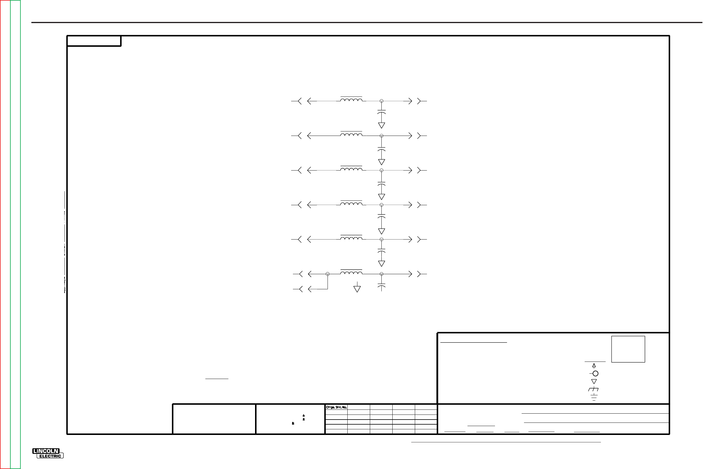
NOTE: Lincoln Electric assumes no responsibility for liablilities resulting from board level troubleshooting. PC Board repairs will invalidate your factory warranty. Individual Printed Circuit Board Components are not available from Lincoln Electric. This information is pro-
vided for reference only. Lincoln Electric discourages board level troubleshooting and repair since it may compromise the quality of the design and may result in danger to the Machine Operator or Technician. Improper PC board repairs could result in damage to the
machine.
ELECTRICAL DIAGRAMS G-19
PRECISION TIG 275
®®
SCHEMATIC-PROTECTION P.C. BOARD (M16115)
SUPPLY VOLTAGE NET
FRAME CONNECTION
COMMON CONNECTION
3000V
.0047
C4
J23
1
J23
4
EARTH GROUND CONNECTION
POWER SUPPLY SOURCE POINT
NOTES :
WITHOUT AFFECTING THE INTERCHANGEABILITY OF A COMPLETE BOARD, THIS DIAGRAM MAY
NOT SHOW THE EXACT COMPONENTS OR CIRCUITRY OF CONTROLS HAVING A COMMON CODE
NUMBER.
N.A. SINCE COMPONENTS OR CIRCUITRY ON A PRINTED CIRCUIT BOARD MAY CHANGE
J23
2
MFD
CAPACITORS =
RESISTORS = Ohms (
UNLESS OTHERWISE SPECIFIED)
1A, 400V
ELECTRICAL SYMBOLS PER E1537
DIODES =
UNLESS OTHERWISE SPECIFIED)
GENERAL INFORMATION
(
1/4W
.022/50V
LABELS
(UNLESS OTHERWISE SPECIFIED)
_
_
_
LAST NO. USED
D-
R-
C-
J23
5
J23
3
.39mH
L4
.39mH
L1
J22
5
J22
4
J22
1
J22
2
J22
6
3000V
.0047
C5
3000V
.0047
C1
3000V
.0047
C2
3000V
.0047
C6
J22
3
.39mH
L2
J23
8
3000V
.0047
C3
.39mH
L6
.39mH
L3
J23
7
.39mH
L5
16115
5-29-90SPA
SQARE WAVE TIG 350
PROTECTION P.C. BOARD SCHEMATIC
MK/DRS
NONE
16115
GM/BS 1-12-90
t
UNLESS OTHERWISE SPECIFIED TOLERANCE
ON HOLE SIZES PER E2056
ON 2 PLACE DECIMALS IS .02
WITH PUBLISHED STANDARDS.
ON 3 PLACE DECIMALS IS .002
ON ALL ANGLES IS .5 OF A DEGREE
MATERIAL TOLERANCE (" ") TO AGREE
THE LINCOLN ELECTRIC CO.
CLEVELAND, OHIO U.S.A.
EQUIP.
TYPE
SCALE
SUBJECT
DR DATE CHK REF. SUP'S'D'G
SHT.
NO.
THE LINCOLN ELECTRIC CO.
THIS SHEET CONTAINS PROPRIETARY INFORMATION
OWNED BY AND IS
NOT TO BE REPRODUCED, DISCLOSED OR USED
THE LINCOLN ELECTRIC CO.
M
M
WITHOUT THE EXPRESS PERMISSION OF
G-19
Return to Section TOC Return to Section TOC Return to Section TOC Return to Section TOC
Return to Master TOC Return to Master TOC Return to Master TOC Return to Master TOC
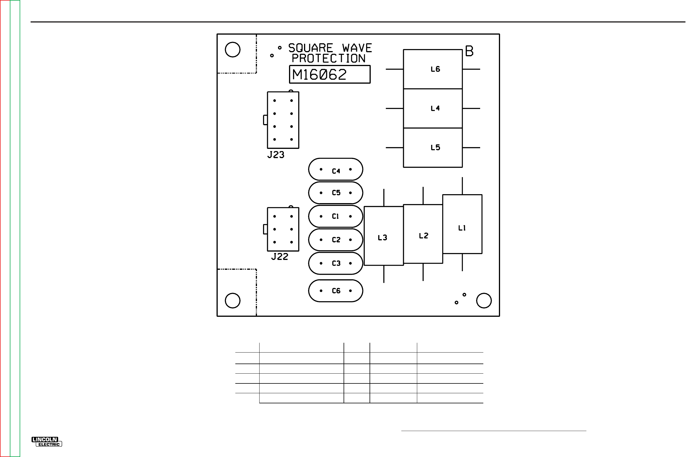
NOTE: Lincoln Electric assumes no responsibility for liablilities resulting from board level troubleshooting. PC Board repairs will invalidate your factory warranty. Individual Printed Circuit Board Components are not available from Lincoln Electric. This information is pro-
vided for reference only. Lincoln Electric discourages board level troubleshooting and repair since it may compromise the quality of the design and may result in danger to the Machine Operator or Technician. Improper PC board repairs could result in damage to the
machine.
ELECTRICAL DIAGRAMS G-20
PRECISION TIG 275
®®
PC BOARD ASSEMBLY-PROTECTION (M16062-1)
IDENTIFICATION
.0047/3000 V
.39 mH
HEADER
HEADER
P.C. BD BLANK
T11577-58
T12218-9F
S18248-6
S18248-8
L8081-B
PART NO.
REQ'D
6
6
1
1
1
C1, C2, C3, C4, C5, C6
-1
L1, L2, L3, L4, L5, L6
J22
J23
1
9-28-2001M
CAPACITORS = MFD/VOLTS
ITEM
M16062M16062-1-1
G-20
Return to Section TOC Return to Section TOC Return to Section TOC Return to Section TOC
Return to Master TOC Return to Master TOC Return to Master TOC Return to Master TOC
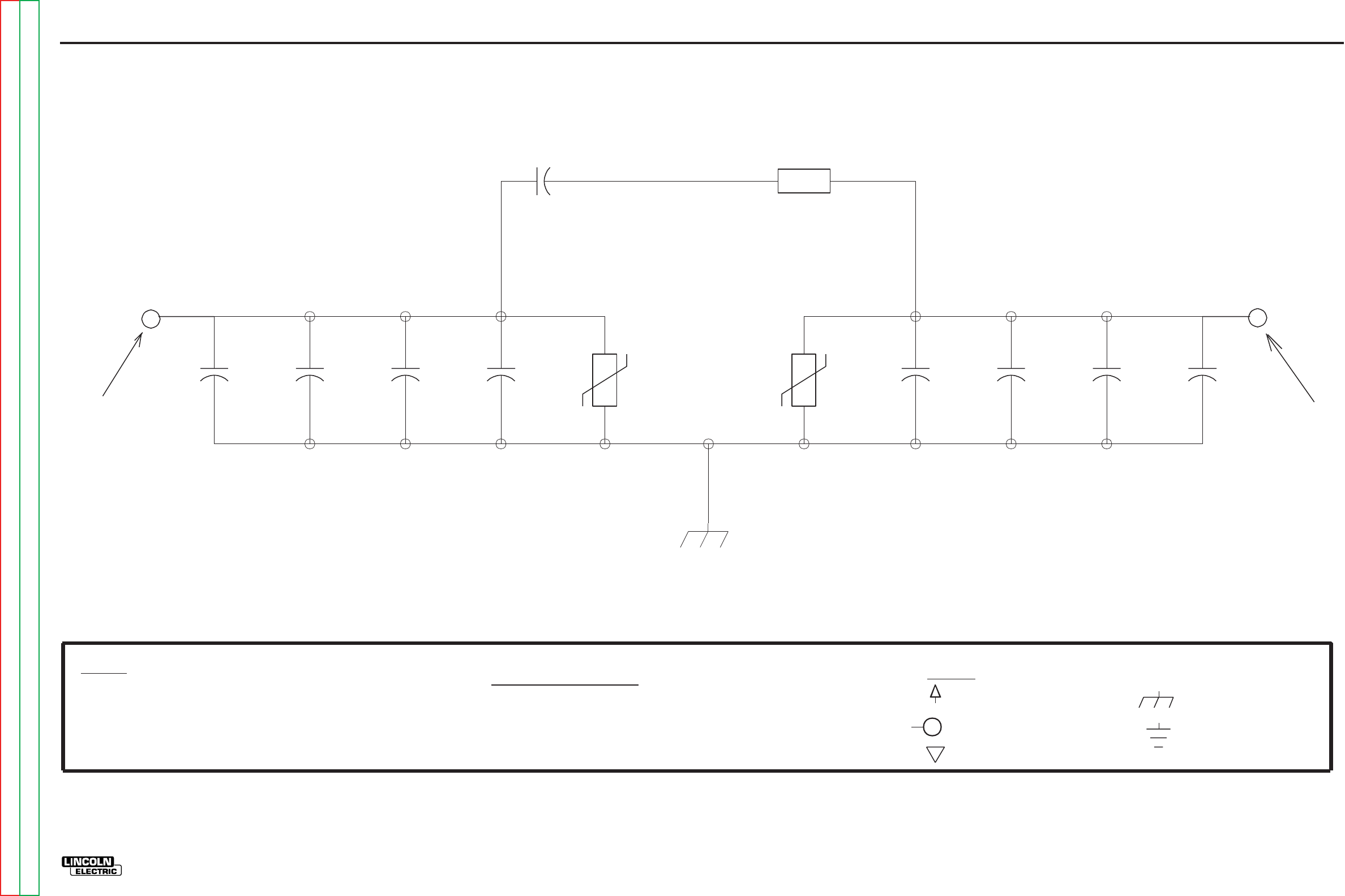
ELECTRICAL DIAGRAMS G-21
PRECISION TIG 275
®®
SCHEMATIC-BYPASS / STABILIZER P.C. BOARD (S22530-1) (CODE 10806 & 10807)
160J
320V
TP1
600V
.05
C8
5W
10
R1
250V
15
C9
600V
.05
C6
600V
.05
C7
600V
.05
C5
600V
.05
C2
600V
.05
C3
600V
.05
C4
600V
.05
C1
GND
GND CONNECTION MADE THROUGH SOLDER PAD
CODE NUMBER.
UNLESS OTHERWISE SPECIFIED)
BOARD.
SUPPLY
THE INTERCHANGEABILITY
CIRCUIT BOARD
MAY CHANGE
OR CIRCUITRY OF
NOTES :
THIS DIAGRAM MAY NOT
DIODES =
UNLESS OTHERWISE SPECIFIED)
CONNECTION MADE THROUGH
WITHOUT AFFECTING
LABELS
S22530-1B0
Rev A
GENERAL INFORMATION
ARC STABILIZER
A PRINTED
(
1/4W
OF A COMPLETE
ELECTRICAL SYMBOLS PER E1537
EARTH GROUND CONNECTION
Graphic
Graphic
FRAME CONNECTION
ARC STABILIZER CAPACITOR
RESISTOR
N.A.
SHOW THE EXACT COMPONENTS
COMMON CONNECTION
AND SCREW TO STEEL STANDOFF ON MACHINE
MFD
.022/50V
CAPACITORS =
(UNLESS OTHERWISE SPECIFIED)
SINCE COMPONENTS OR CIRCUITRY ON
RESISTORS = Ohms (
POWER SUPPLY SOURCE POINT
VOLTAGE NET
1A, 400V
CONTROLS HAVING A COMMON
CONNECTION MADE THROUGH
HOLE WITH SOLDER PAD HOLE WITH SOLDER PAD
160J
320V
TP2
G-21
NOTE: This diagram is for reference only. It may not be accurate for all machines covered by this manual.
Return to Section TOC Return to Section TOC Return to Section TOC Return to Section TOC
Return to Master TOC Return to Master TOC Return to Master TOC Return to Master TOC
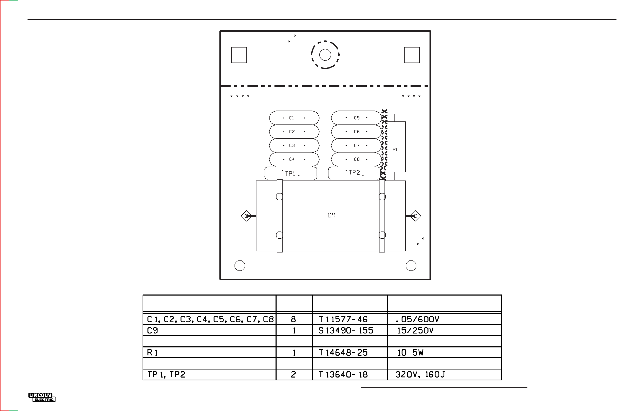
NOTE: Lincoln Electric assumes no responsibility for liablilities resulting from board level troubleshooting. PC Board repairs will invalidate your factory warranty. Individual Printed Circuit Board Components are not available from Lincoln Electric. This information is pro-
vided for reference only. Lincoln Electric discourages board level troubleshooting and repair since it may compromise the quality of the design and may result in danger to the Machine Operator or Technician. Improper PC board repairs could result in damage to the
machine.
ELECTRICAL DIAGRAMS G-22
PRECISION TIG 275
®®
PC BOARD ASSEMBLY-BYPASS / STABILIZER (L10121-1) (CODE 10806 & 10807)
IDENTIFICATIONIDENTIFICATION
PART NO.PART NO.
REQ'DREQ'DITEMITEM
BYPASS STABILIZERL10121-1
XXX
XXXXXXXXXXX
XXXXXXXXXXX XXX
XXXXXXXXXXX XXX
L10121-1
Rev B
G-22
Return to Section TOC Return to Section TOC Return to Section TOC Return to Section TOC
Return to Master TOC Return to Master TOC Return to Master TOC Return to Master TOC
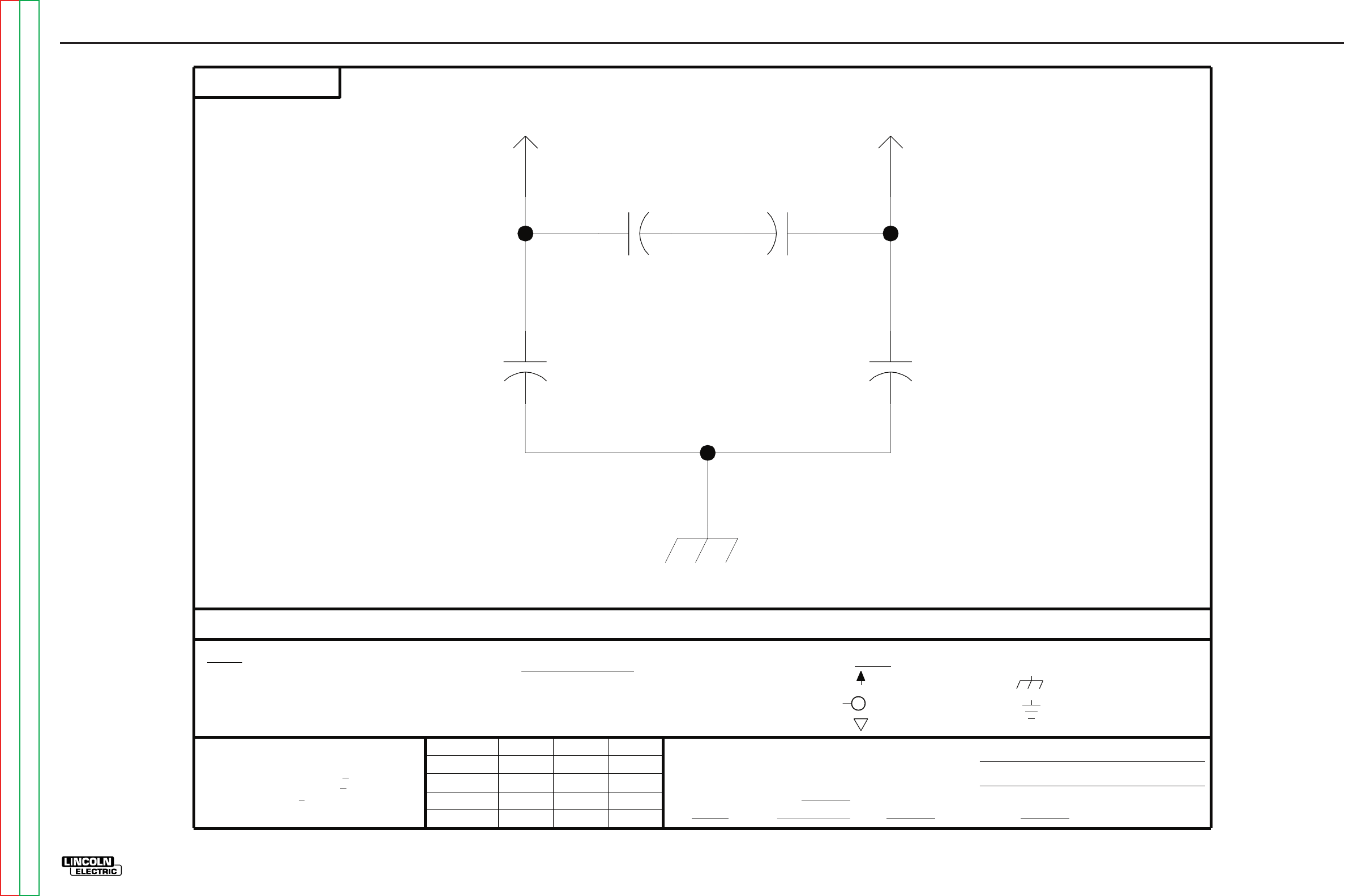
ELECTRICAL DIAGRAMS G-23
PRECISION TIG 275
®®
SCHEMATIC-BYPASS AND CE P. C. BOARD (S24206) (CODE 10893)
VOLTAGE NET
.0047
440V
C2
.0047
440V
C1
2.2
275V
C4
2.2
275V
C3
B1
FRAME GROUND
9/29/97
LINE 2 (V)
LINE 1 (U)
DIODES =
FRAME CONNECTION
(
CODE NUMBER.
GENERAL INFORMATION
APM
SUPPLY
A PRINTED
THIS DIAGRAM MAY NOT
RESISTORS = Ohms (
(UNLESS OTHERWISE SPECIFIED)
UNLESS OTHERWISE SPECIFIED TOLERANCE
COMMON CONNECTION
TYPE
CLEVELAND, OHIO U.S.A.
SUBJECT
24206
S
ON 3 PLACE DECIMALS IS + .OO2
Ch'ge.Sht.No.
OR CIRCUITRY OF
SHT.
NO.
DR.
DATE
SUP'S'D'G.
SCALE
ON 2 PLACE DECIMALS IS + .O2
THE LINCOLN ELECTRIC CO.
1A, 400V
NONE
MAY CHANGE
EARTH GROUND CONNECTION
UNLESS OTHERWISE SPECIFIED)
THIS SHEET CONTAINS PROPRIETARY INFORMATION OWNED BY
THE LINCOLN ELECTRIC CO.
AND IS NOT TO BE REPRODUCED, DISCLOSED OR USED WITHOUT THE EXPRESS PERMISSION OF
UNLESS OTHERWISE SPECIFIED)
THE LINCOLN ELECTRIC CO.
CIRCUIT BOARD
S
WITH PUBLISHED STANDARDS
WITHOUT AFFECTING
THE INTERCHANGEABILITY
SHOW THE EXACT COMPONENTS
EQUIP.
NOTES :
MFD
.022/50V
24206
CAPACITORS =
BOARD.
SINCE COMPONENTS OR CIRCUITRY ON
ON ALL ANGLES IS + .5 OF A DEGREE
MATERIAL TOLERANCE ("t") TO AGREE
CHK.
POWER SUPPLY SOURCE POINT
CONTROLS HAVING A COMMON
ELECTRICAL SYMBOLS PER E1537
LABELS
ON HOLES SIZES PER E-2056
N.A.
OF A COMPLETE
1/4W
B2
XA
SCHEMATIC, BYPASS
3-20-98
FILE NAME: S24206_1AA
G-23
NOTE: This diagram is for reference only. It may not be accurate for all machines covered by this manual.
Return to Section TOC Return to Section TOC Return to Section TOC Return to Section TOC
Return to Master TOC Return to Master TOC Return to Master TOC Return to Master TOC
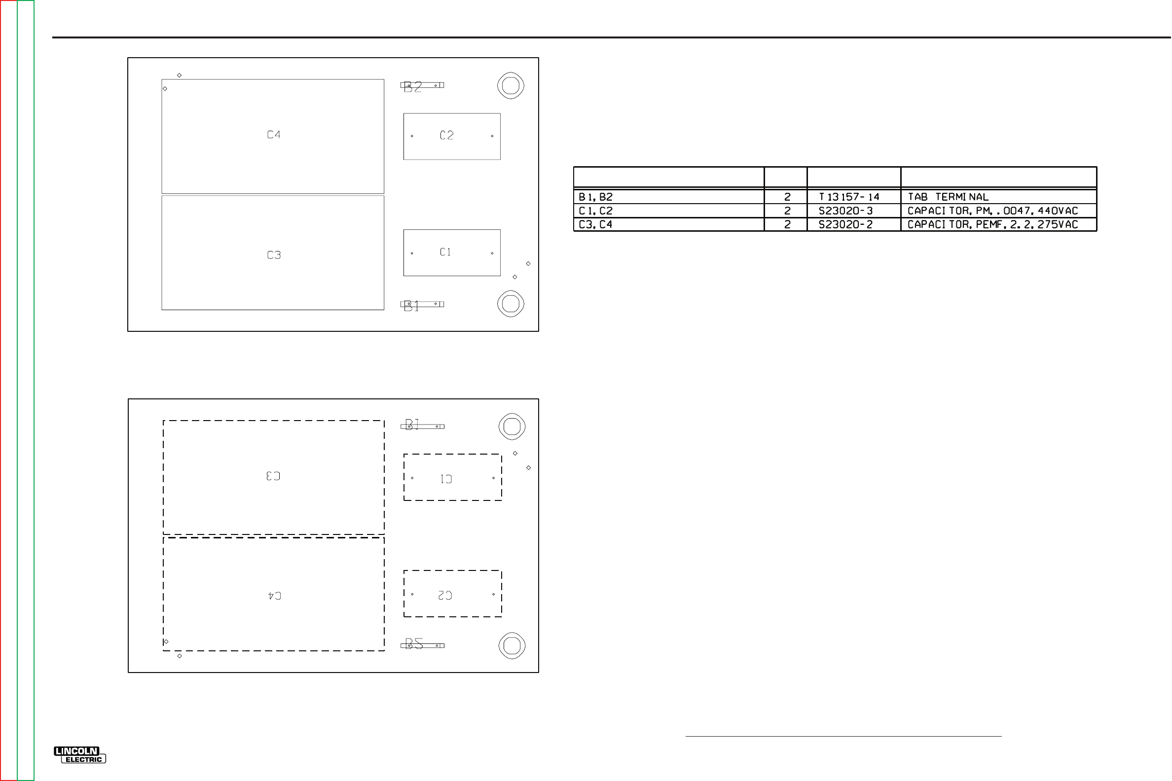
NOTE: Lincoln Electric assumes no responsibility for liablilities resulting from board level troubleshooting. PC Board repairs will invalidate your factory warranty. Individual Printed Circuit Board Components are not available from Lincoln Electric. This information is pro-
vided for reference only. Lincoln Electric discourages board level troubleshooting and repair since it may compromise the quality of the design and may result in danger to the Machine Operator or Technician. Improper PC board repairs could result in damage to the
machine.
ELECTRICAL DIAGRAMS G-24
PRECISION TIG 275
®®
PC BOARD ASSEMBLY-BYPASS AND CE (L10882-1) (CODE 10893)
3-20-98
10882-1
L
IDENTIFICATION
PART NO.
REQ'DITEM
BYPASS L10882-1
BYPASS L10882-1
xxxx
x
xxx
x
x
x
x
x
x
x
x
x
x
x
xxxx
x
x
x
x
x
xx
xx
xxxx
xxxx
x
x
x
x
x
x
x
x
x
x
x
xxxx
xxx
x
x
x
BOTTOM VIEW
G-24
Return to Section TOC Return to Section TOC Return to Section TOC Return to Section TOC
Return to Master TOC Return to Master TOC Return to Master TOC Return to Master TOC
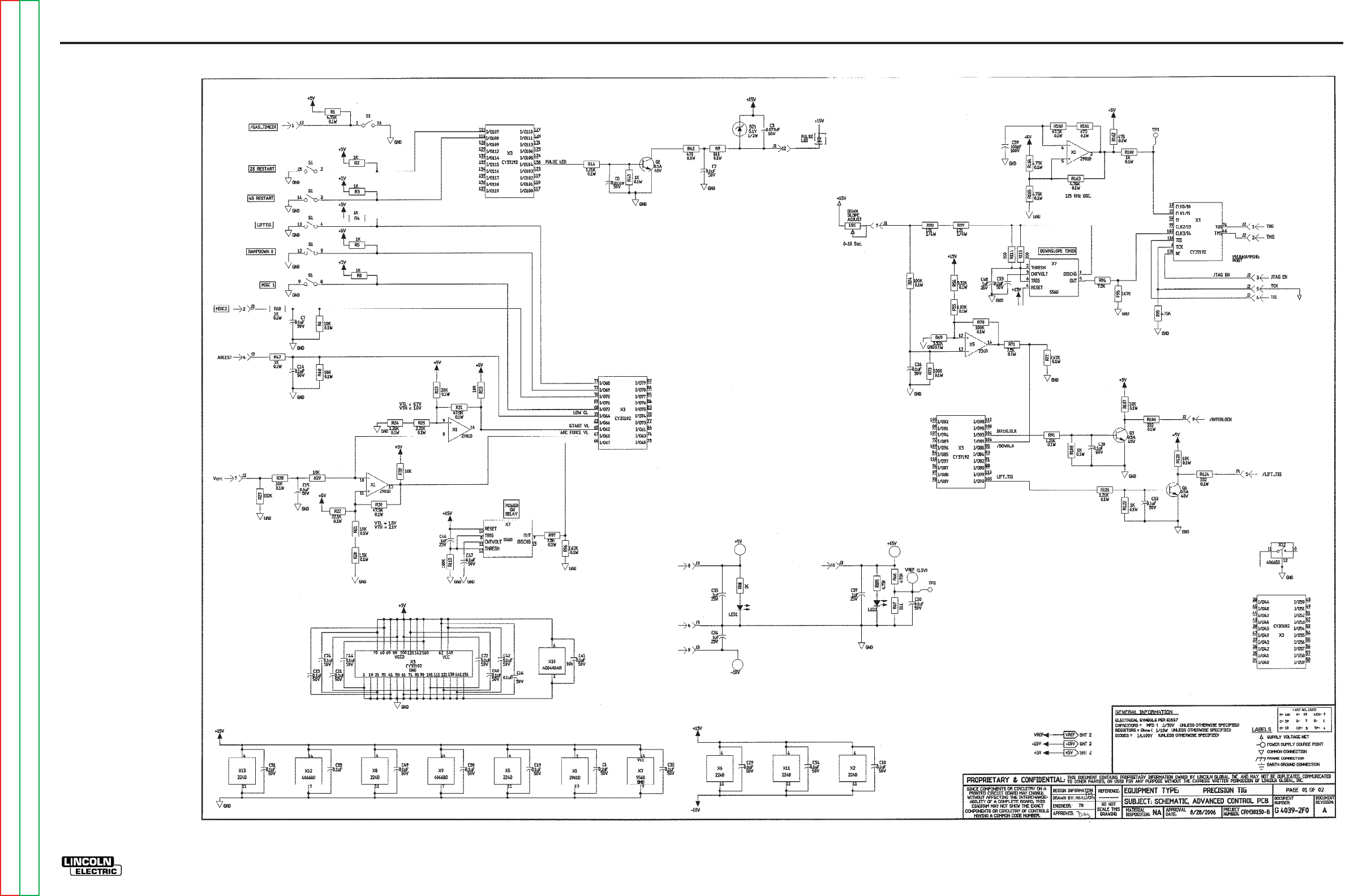
ELECTRICAL DIAGRAMS G-25
PRECISION TIG 275
®®
SCHEMATIC - TIG OPTION P.C. BOARD - BELOW CODE 11000 (G4039 PAGE 1)
G-25
NOTE: This diagram is for reference only. It may not be accurate for all machines covered by this manual.
Return to Section TOC Return to Section TOC Return to Section TOC Return to Section TOC
Return to Master TOC Return to Master TOC Return to Master TOC Return to Master TOC
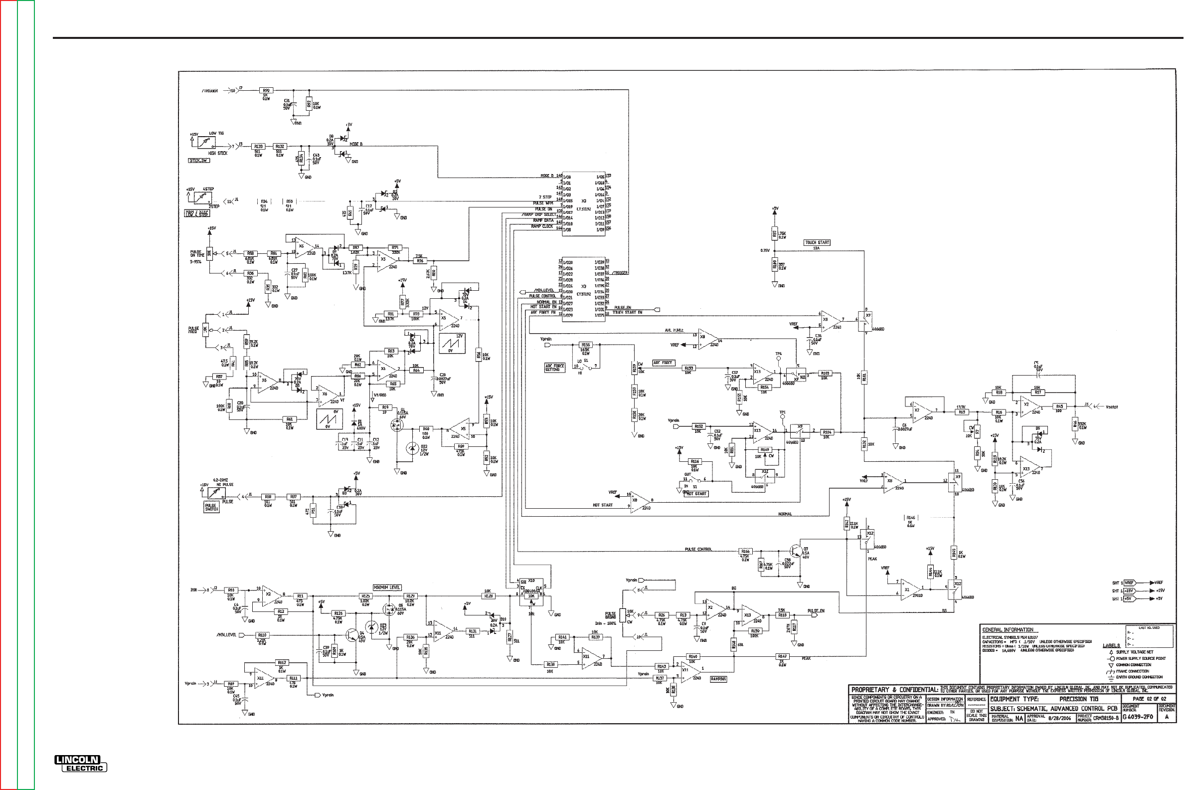
ELECTRICAL DIAGRAMS G-26
PRECISION TIG 275
®®
SCHEMATIC - TIG OPTION P.C. BOARD - BELOW CODE 11000 (G4039 PAGE 2)
G-26
NOTE: This diagram is for reference only. It may not be accurate for all machines covered by this manual.
Return to Section TOC Return to Section TOC Return to Section TOC Return to Section TOC
Return to Master TOC Return to Master TOC Return to Master TOC Return to Master TOC
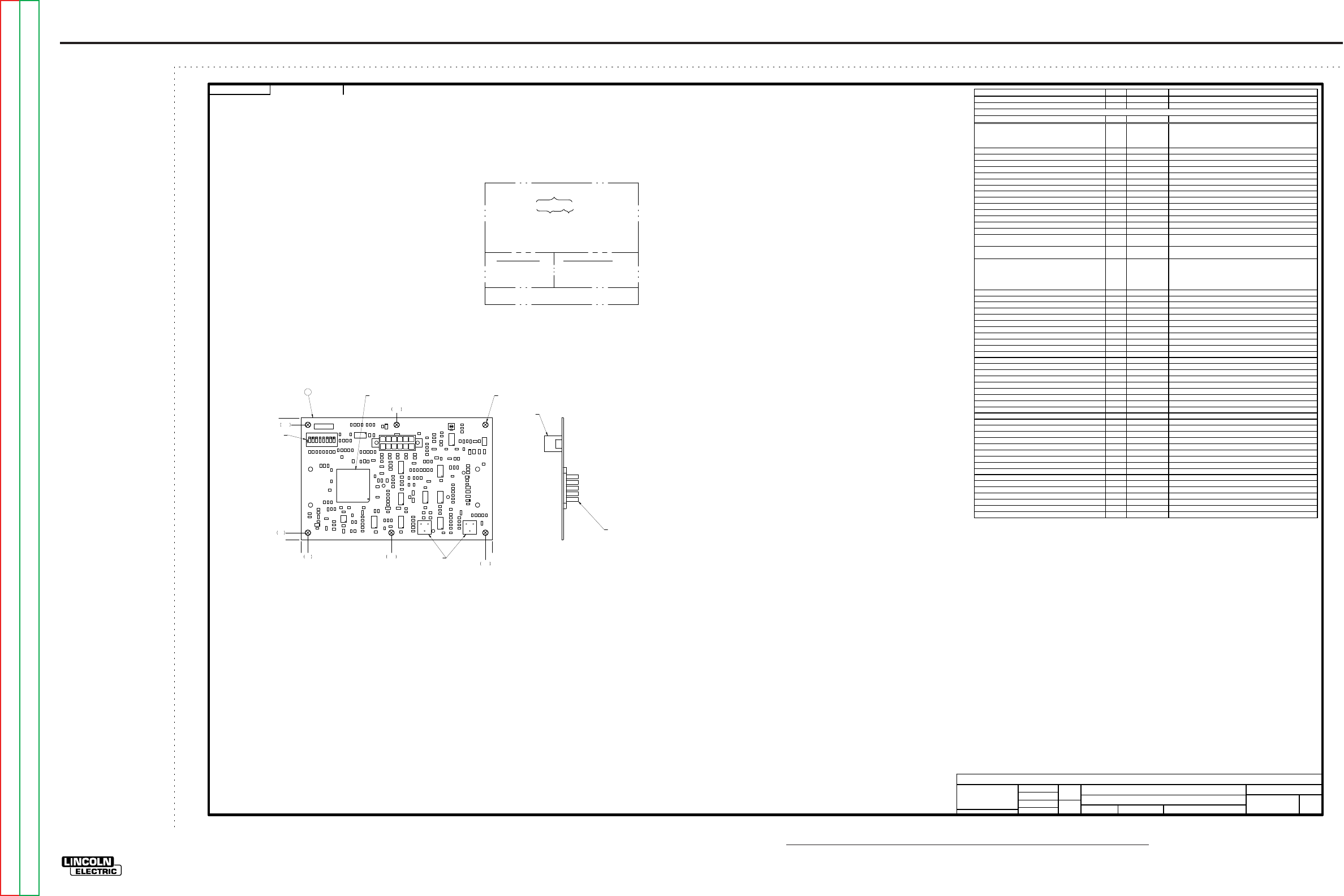
NOTE: Lincoln Electric assumes no responsibility for liablilities resulting from board level troubleshooting. PC Board repairs will invalidate your factory warranty. Individual Printed Circuit Board Components are not available from Lincoln Electric. This information is pro-
vided for reference only. Lincoln Electric discourages board level troubleshooting and repair since it may compromise the quality of the design and may result in danger to the Machine Operator or Technician. Improper PC board repairs could result in damage to the
machine.
ELECTRICAL DIAGRAMS G-27
PRECISION TIG 275
®®
PC BOARD ASSEMBLY - TIG OPTION P.C. BOARD - BELOW CODE 11000 (G4040-2)
UNLESS OTHERWISE SPECIFIED:
CAPACITANCE = MFD/VOLTS
INDUCTANCE = HENRIES
RESISTANCE = OHMS
G4040-2
INDUSTRIAL TIG
ADVANCED CONTROL PC BOARD ASSEMBLY
1:1
G4040-1
FEI
-
UNLESS OTHERWISE SPECIFIED TOLERANCE
MANUF ACTURING TOLERANC E PER E2056
ON 2 PLA CE DE CIMA LS IS ± .0 2
ON 3 PLACE DEC IMALS IS ± .002
ON AL L A N GLES IS ± .5 OF A DE G REE
WITH PUB LIS HE D STAN DA R DS.
MATER IAL T O LE RA NCE (" ") T O AG REE
t
DO NOT SCAL E THI S DR AWING
DRAWN BY:
DESIG N INF ORMATIO N
ENGI NEER:
APPR OVED:
REFERENCE:
EQUIPMENT TYPE:
SUBJECT:
SCA LE:
MATERIAL
DISPOSITION: APPROVAL
DATE: PROJECT
NUMBER:
UF CRM34409
1
PAGE ___ OF ___
1
ENGINEERING CONTROLLED
MANUFACTURER: Yes
DOCUMENT
NUMBER: DOCUMENT
REVISION:
THIS DOCUMEN T CON TAINS PROPRIETARY INFORMATION O WNED BY LINCOLN G LOBAL, INC. AND MA Y NOT BE DUPLICATED, COM MUNICATED
TO O THER PARTIES OR USED FOR AN Y PURPOSE WITHOU T THE EXPRESS WRIT TEN PERMISSION OF LINCOLN GL OBAL, INC.
PROPRIETARY & CONFIDENTIAL:
B
3/16/2007
REVISED MANUFACTURER SPECIFICA TION
CHANGE DETAIL:
SOLID EDGE
STRP
G4040-2
NOTES:
N.A. CAUTION: THIS DEVICE IS SUBJECT TO DAMAGE BY STATIC ELECTRICITY. SEE E2454
BEFORE HANDLING.
N.B. PROGRAM X3 WITH ITEM 2.
N.D. DO NOT COAT WITH ENCAPSULATION MATERIAL.
N.E. KEEP MOUNTING HOLES FREE OF ENCAPSULATION MATERIAL. (5 PLACES)
N.F. KEEP TOP SURFACE OF TRIMMERS FREE OF ENCAPSULATION MATERIAL. (2 PLACES)
N.G. KEEP TOP SURFACE OF DIP SWITCH FREE OF ENCAPSULATION MATERIAL.
R9
C1 5
C2 8
R113
C6
R136
R47
R15
R104
D3
R31
R14
R44
R64
R62
R137
C18
J1
R94
R147
D1 0
R80
C12
R111
C1 6
R99
C36
R110
R101
X3
R91
R87
R139
R5
R130
R28
R59
R30
S1
R133
R56
X7
R24
Q3
X12
D1
C24
TP4
R40
R63 X2
R135
C26
X11 R 112
R126
X1
C3
C10
TP2
R25
C4
X9
R108
C2 3
R161
C2
X13
R123
C4 5
TP3
R119
R118
X8
R89
R149
R2
R134
R7
R35
R68
X5
D7
R145
R159
R143
Q4
C11
R98
TP1
R57
DZ2
C37
R154
X6
R49
R166
C3 3
R3
C55
R65
R17
C3 1
R81
R127
R124
R39
C29
R71
X10
C5
R88
C47
R13
R95
R162
C49
R138
R125
R131
R70
R157
R18
R144
R58
C50
R96
R21
R53
R92
R73
R8
R97
C44
R168
R46
R12
R115
R163
D6
Q1
C38
R160
R120
R61
R10
R74
C3 9
R114
R69
R156
C56
C7
Q7
R164
R29
R116
C2 0
D5
Q6
R132
DZ3
R38
C13
R85
C48
C4 3
R105
R27
R158
C40
R16
R22
R51
R50
C19
C1 4
R90
R79
R129
R67
R37
C2 1
R54
R84
D9
R43
R153
R36
R148
R151
C1 7
C57
C2 2
R146
R6
R19
R83
R72
R11
R150
Q5
R106
R109
DZ1
R82
R4
C32
R93
C34
C51
C1
R76
R66
R128
R34
R75
R140
C5 3
R52
R165
R60
R86
R48
C5 9
R121
R42
C54
R32
R107
D4
C8 Q2
D2
R78
R102
C5 8
C2 7
C35
R152
R155
R117
R41
R55
R122
R77
R20
C42
R1
R33
R167
D8
R100
R23
C46
R142
C9
R26
C41
R141
LED2
R103
R45
LED1
C30
C52
N
O
G4040-2
76543281
PRECISION TIG ADVANCED CONTROL
ARC FORCEHOT START
JI
J2, J3MOUNTED
ON BACK OF BOARD
0 5.50
0
1N.B. N.E.
N.F.
N.G.
ALL COMPONENTS AND MATERIALS USED IN THIS
ASSEMBLY ARE TO BE RoHS COMPLIANT PER E4253.
ITEM QTY PART NUMBER DESCRIPTION
1 1 G4040-F PC BOARD BLANK
2 1 S25409-1 SOFTWARE CPLD (X3)
REFERENCES QTY PART NUMB ER DESCRIPTION
C1, C2, C4, C5, C7, C9, C10, C14, C15, C16, C17, C18,
C19, C21, C22, C23, C24, C26, C27, C28, C29, C30, C31,
C32, C33, C34, C38, C39, C40, C41, C42, C43, C44, C45,
C47, C49, C50, C51, C52, C53, C54, C55, C56, C57
44 S25020-3SMT CAPACITOR,SMD,CERAMIC,0.1MF,50V,10%,X7R,S0805
C3, C8, C58 3 S25020-2SMT CAPACITOR,SMD,CERAMIC,0.022MF,50V,10%,X7R,S0805
C6, C20 2 S25020-5SMT CAPACITOR,SMD,CERAMIC,2700pF,50V,5%,X7R,S0805
C11, C12, C13, C35, C36, C37, C46, C48 8 S25020-24SMT CAPACITOR,SMD,CERAMIC,1.0MF,25V,10% ,X7R,S1206
C59 1 S25020-12SMT CAPACITOR,SMD,CERAMIC,100pF,100V,5%,COG,S0805
D1 1 S25040-2SMT DIODE,SMD,1A,400V,DO-214BA/AC
D2, D3, D8, D10 4 S25049-4SMT DIODE,SMD,SCHOTTKY,DUAL,0.200A,30V,SOT-23
D4, D5, D6, D7, D9 5 S25040-5SMT DIODE,SMD,DUAL,0.200A,70V,UFR
DZ1 1 S25046-1SMT ZENER DIODE,SMD,0.5W,5.1V, 5%,SOD123
DZ2, DZ3 2 S25046-4SMT ZENER DIODE,SMD,0.5W,12V,5%,SOD-123
N.D. J1 1 S24020-12 CONNECTOR,MOLEX,MINI,PCB,12-PIN,TIN
N.D. J2, J3 2 S21135-10 CONNECTOR,MOLEX,MINI,BLIND,F,10-PIN
LED1, LED2 2 S25080-2SMT LED,SMD,GREEN,CLEAR,S1206
Q1, Q5 2 S25051-4SMT TRANSISTOR,SMD,NMF,SOT-23,0.115A,60V,7002LT1(SS)
Q2, Q3, Q4, Q6, Q7 5 S25050-1SMT TRANSISTOR,SMD,NPN,0.5A,40V,SOT-23,MMBT4401LT1
R1, R13, R26, R66, R87, R93, R105, R126, R163, R164,
R165, R166, R167 13 S25000-4751SMT RESISTOR,SMD,METAL FILM,1/10W,4.75K,1%,S0805
R2, R3, R4, R5, R8, R12, R43, R47, R68, R88, R90, R108,
R109, R112, R122, R145, R146, R147, R160 19 S25000-1001SMT RESISTOR,SMD,METAL FILM,1/10W,1.00K,1%,S0805
R6, R10, R14, R16, R17, R18, R21, R28, R29, R32, R33,
R48, R52, R53, R56, R61, R63, R64, R65, R89, R92, R101,
R102, R103, R104, R107, R116, R120, R123, R128, R130,
R135, R137, R138, R139, R140, R141, R143, R151, R152,
R153, R154, R155, R157
44 S25000-1002SMT RESISTOR,SMD,METAL FILM,1/10W,10.0K,1%,S0805
R7 1 S25058-1SMT TRIMMER,SMD,ST,1/4W,10K,10%,LINEAR
R9, R34, R37, R38, R50, R67, R127, R131, R132, R133 10 S25000-5110SMT RESISTOR,SMD,METAL FILM,1/10W,511OHMS,1%,S0805
R11, R42, R49, R51, R111, R134, R161, R162 8 S25000-4750SMT RESISTOR,SMD,METAL FILM,1/10W,475OHMS,1%,S0805
R15, R79, R81 3 S25000-1372SMT RESISTOR,SMD,METAL FILM,1/10W,13.7K,1%,S0805
R19, R57 2 S25000-10R0SMT RESISTOR,SMD,METAL FILM,1/10W,10.0OHMS,1%,S0805
R20 1 S25000-1501SMT RESISTOR,SMD,METAL FILM,1/10W,1.50K,1%,S0805
R22, R142, R144 3 S25000-2212SMT RESISTOR,SMD,METAL FILM,1/10W,22.1K,1%,S0805
R23, R62, R86, R136, R158 5 S25000-2002SMT RESISTOR,SMD,METAL FILM,1/10W,20.0K,1%,S0805
R24, R44, R91, R110, R121 5 S25000-1211SMT RESISTOR,SMD,METAL FILM,1/10W,1.21K,1%,S0805
R25 1 S25000-2211SMT RESISTOR,SMD,METAL FILM,1/10W,2.21K,1%,S0805
R27, R46, R75 3 S25000-3323SMT RESISTOR,SMD,METAL FILM,1/10W,332K,1%,S0805
R30, R31, R168 3 S25000-4752SMT RESISTOR,SMD,METAL FILM,1/10W,47.5K,1%,S0805
R35, R36, R106, R124 4 S25000-3320SMT RESISTOR,SMD,METAL FILM,1/10W,332OHMS,1%,S0805
R39 1 S25000-4753SMT RESISTOR,SMD,METAL FILM,1/10W,475K,1%,S0805
R40, R45 2 S25000-1000SMT RESISTOR,SMD,METAL FILM,1/10W,100OHMS,1%,S0805
R41 1 S25000-47R5SMT RESISTOR,SMD,METAL FILM,1/10W,47.5OHMS,1%,S0805
R54, R69, R77 3 S25000-3321SMT RESISTOR,SMD,METAL FILM,1/10W,3.32K,1%,S0805
R55, R82, R125 3 S25000-1821SMT RESISTOR,SMD,METAL FILM,1/10W,1.82K,1%,S0805
R58, R84 2 S25000-6811SMT RESISTOR,SMD,METAL FILM,1/10W,6.81K,1%,S0805
R59 1 S25000-3922SMT RESISTOR,SMD,METAL FILM,1/10W,39.2K,1%,S0805
R60, R70, R73, R74, R78, R83, R113, R150 8 S25000-1003SMT RESISTOR,SMD,METAL FILM,1/10W,100K,1%,S0805
R71, R76, R94, R97, R118 5 S25000-7501SMT RESISTOR,SMD,METAL FILM,1/10W,7.50K,1%,S0805
R72, R80, R95, R96, R117 5 S25000-2671SMT RESISTOR,SMD,METAL FILM,1/10W,2.67K,1%,S0805
R85, R119, R129 3 S25000-1822SMT RESISTOR,SMD,METAL FILM,1/10W,18.2K,1%,S0805
R98, R99 2 S25001-1210SMT RESISTOR,SMD,121OHMS,1/4W,1206,1%,TR
R100 1 S25000-3570SMT RESISTOR,SMD,METAL FILM,1/10W,357OHMS,1%,S0805
R114, R115 2 S25000-2000SMT RESISTOR,SMD,METAL FILM,1/10W,200OHMS,1%,S0805
R148 1 S25000-6810SMT RESISTOR,SMD,METAL FILM,1/10W,681OHMS,1%,S0805
R149, R159 2 T10812-41 TRIMMER,ST,1/2W,10K, 10%,LINEAR
R156 1 S25000-1652SMT RESISTOR,SMD,METAL FILM,1/10W,16.5K,1%,S0805
S1 1 S19869-8 SWITCH,DIP,SPST,8-CIRCUITS????SET_SWITCH_POSITIONS????
N.A. X1 1 S15128-11SMT IC,SMD,COMPARATOR,QUAD,2901D
N.A. X2, X5, X6, X8, X11, X13 6 S15128-4SMT OP-AMP,SMD,QUAD, GEN-PURPOSE,224D
N.A. X3 1 S25070-12SMT IC,SMD,CMOS,CPLD,CY37192,160-TQFP(SS)
N.A. X7 1 S25067-1SMT IC,BIPOLAR,TIMER,SOIC-14
N.A. X9, X12 2 S15018-6SMT IC,SMD,CMOS,SWITCH,ANALOG,QUAD, 4066BD(SS)
N.A. X10 1 S25057-2SMT POT,SMD,DIGITAL,10K,1-CHNL,SOIC-8
REFER TO ELECTRONIC COMPONENT DATABASE FOR SPECIFICATIONS ON ITEMS LISTED BELOW
REVISION CONTROL
G4040-2F0
PART NO. IDENT IFICATION
CODE
TEST PER
COAT WITH E1844 AND E3668
SCHEMATIC REFERENCE:
BUYDETAIL MAKE DETAIL
BUY PER E3867 MANUFACTURE PER E1911-ROHS
BUY BLANK COMPLETE
SEE ELECTRONIC FILE FOR ADDITIONAL INFORMATION.
E3937-AC
(1 COAT EACH)
G4039-2F0
4LAYER BOARD BLANK PANEL
(6 BOARDS PER PANEL)
.20 2.60 5.30
2.75
.20
3.30
3.50
G-27
Return to Section TOC Return to Section TOC Return to Section TOC Return to Section TOC
Return to Master TOC Return to Master TOC Return to Master TOC Return to Master TOC
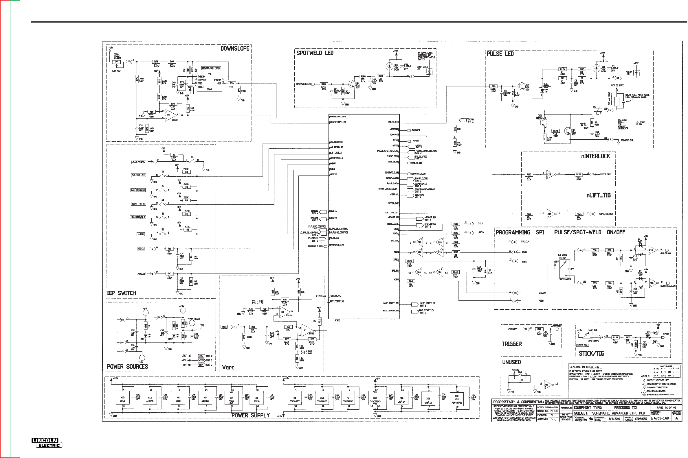
ELECTRICAL DIAGRAMS G-28
PRECISION TIG 275
®®
SCHEMATIC - TIG OPTION P.C. BOARD - ABOVE CODE 11000 (G4760 PAGE 1)
G-28
NOTE: This diagram is for reference only. It may not be accurate for all machines covered by this manual.
Return to Section TOC Return to Section TOC Return to Section TOC Return to Section TOC
Return to Master TOC Return to Master TOC Return to Master TOC Return to Master TOC
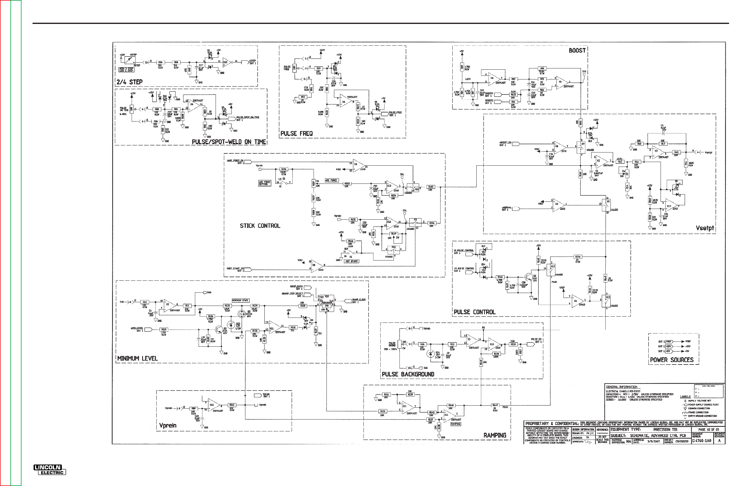
ELECTRICAL DIAGRAMS G-29
PRECISION TIG 275
®®
SCHEMATIC - TIG OPTION P.C. BOARD - ABOVE CODE 11000 (G4760 PAGE 2)
G-29
NOTE: This diagram is for reference only. It may not be accurate for all machines covered by this manual.
Return to Section TOC Return to Section TOC Return to Section TOC Return to Section TOC
Return to Master TOC Return to Master TOC Return to Master TOC Return to Master TOC
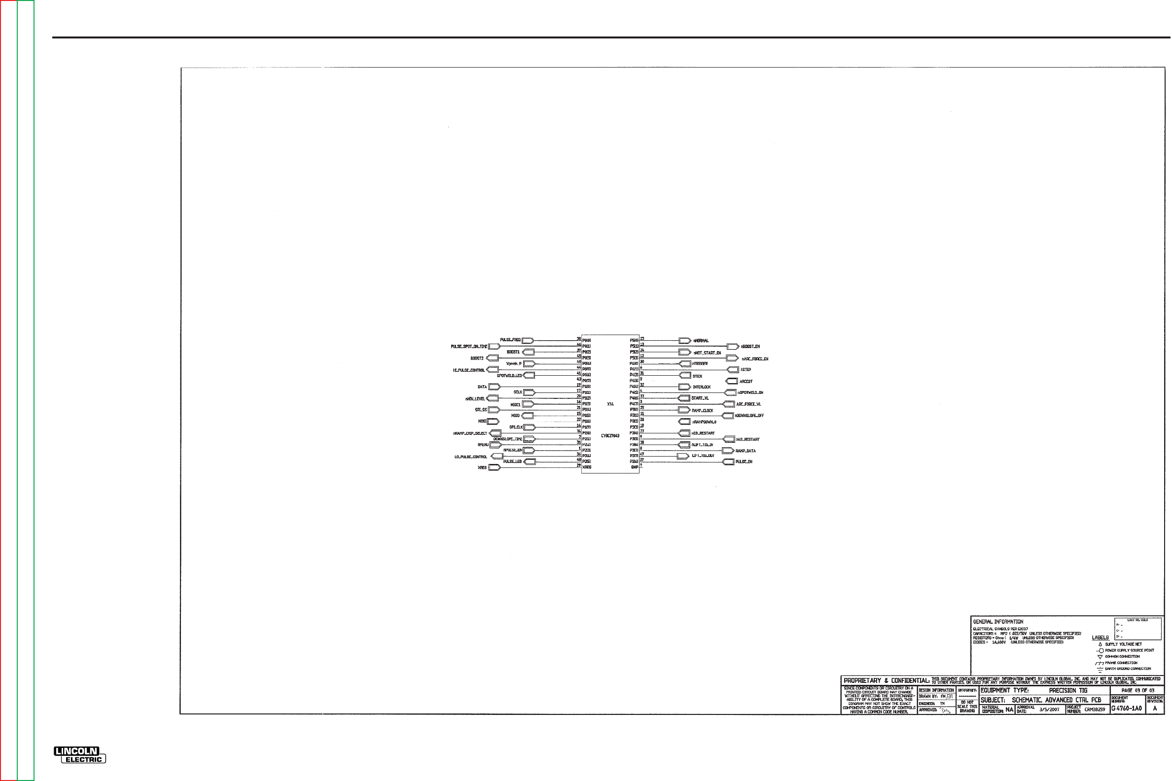
ELECTRICAL DIAGRAMS G-30
PRECISION TIG 275
®®
SCHEMATIC - TIG OPTION P.C. BOARD - ABOVE CODE 11000 (G4760 PAGE 3)
G-30
NOTE: This diagram is for reference only. It may not be accurate for all machines covered by this manual.
Return to Section TOC Return to Section TOC Return to Section TOC Return to Section TOC
Return to Master TOC Return to Master TOC Return to Master TOC Return to Master TOC
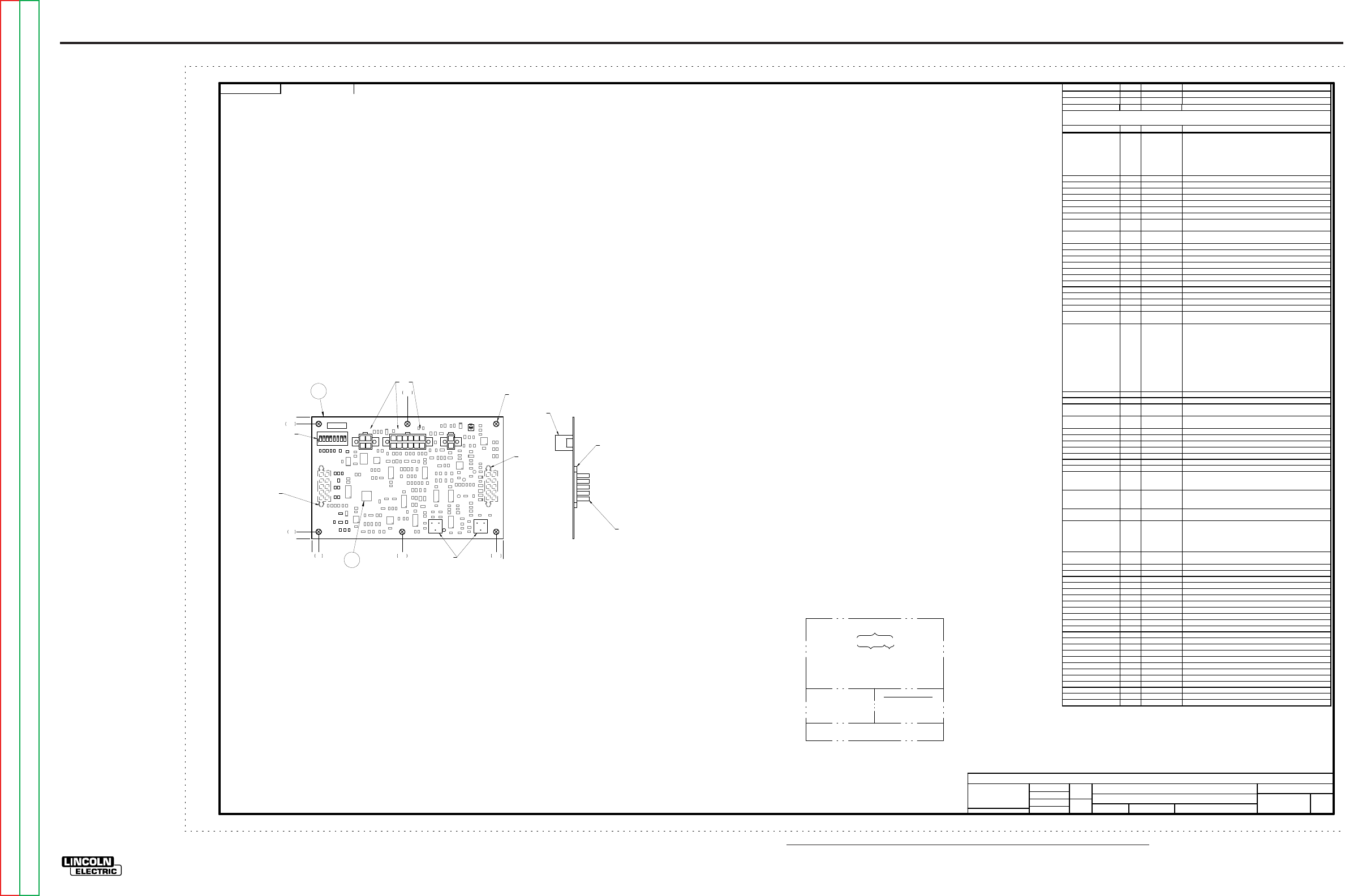
NOTE: Lincoln Electric assumes no responsibility for liablilities resulting from board level troubleshooting. PC Board repairs will invalidate your factory warranty. Individual Printed Circuit Board Components are not available from Lincoln Electric. This information is pro-
vided for reference only. Lincoln Electric discourages board level troubleshooting and repair since it may compromise the quality of the design and may result in danger to the Machine Operator or Technician. Improper PC board repairs could result in damage to the
machine.
ELECTRICAL DIAGRAMS G-31
PRECISION TIG 275
®®
PC BOARD ASSEMBLY - TIG OPTION P.C. BOARD - ABOVE CODE 11000 (G4761-1)
UNLESS OTHERWISE SPECIFIED:
CAPACITANCE = MFD/VOLTS
INDUCTANCE = HENRIES
RESISTANCE = OHMS
G4761-1
INDUSTRIAL TIG
ADVANCED CONTROL PC BOARD ASSEMBLY
1:1
G4040
Jbarto
T Nguyen
-
UNLESS OTHERWISE SPECIFIED TOLERANCE
MANUF ACTURING TOLERANC E PER E2056
ON 2 PLA CE DE CIMA LS IS ± .0 2
ON 3 PLACE DEC IMALS IS ± .002
ON AL L A N GLES IS ± .5 OF A DE G REE
WITH PUB LIS HE D STAN DA R DS.
MATER IAL T O LE RA NCE (" ") T O AG REE
t
DO NOT SCAL E THI S DR AWING
DRAWN BY:
DESIG N INF ORMATIO N
ENGI NEER:
APPR OVED:
REFERENCE:
EQUIPMENT TYPE:
SUBJECT:
SCA LE:
MATERIAL
DISPOSITION: APPROVAL
DATE: PROJECT
NUMBER:
NA CRM38259
1
PAGE ___ OF ___
1
ENGINEERING CONTROLLED
MANUFACTURER: No
DOCUMENT
NUMBER: DOCUMENT
REVISION:
THIS DOCUMEN T CON TAINS PROPRIETARY INFORMATION O WNED BY LINCOLN G LOBAL, INC. AND MA Y NOT BE DUPLICATED, COM MUNICATED
TO O THER PARTIES OR USED FOR AN Y PURPOSE WITHOU T THE EXPRESS WRIT TEN PERMISSION OF LINCOLN GL OBAL, INC.
PROPRIETARY & CONFIDENTIAL:
A
3/5/2007
RELEASED A.01 FROM "X"
CHANGE DETAIL:
SOLID EDGE
STRP
G4761-1
NOTES:
N.A. CAUTION: THIS DEVICE IS SUBJECT TO DAMAGE BY STATIC ELECTRICITY. SEE E2454
BEFORE HANDLING.
N.B. PROGRAM X14 WITH ITEM 2 AND LABEL X14 WITH PART NUMBER OF ITEM 2.
N.C. APPLY ITEM 3 TO COMPONENT SIDE OF BOARD AS SHOWN.
N.D. DO NOT COAT WITH ENCAPSULATION MATERIAL.
N.E. KEEP MOUNTING HOLES FREE OF ENCAPSULATION MATERIAL. (5 PLACES)
N.F. KEEP TOP SURFACE OF TRIMMERS FREE OF ENCAPSULATION MATERIAL. (2 PLACES)
N.G. KEEP TOP SURFACE OF DIP SWITCH FREE OF ENCAPSULATION MATERIAL.
N.H. APPLY ITEM 3 AROUND BASE OF J2 & J3 ON BACK SIDE OF BOARD. LIMIT HEIGHT TO
.125 +0/-.0625 INCHES.
N.J. APPLY ITEM 3 TO CONNECTOR’S PLASTIC MOUNTING PINS.
{
N.A.
{
N.D.
18234567
PRECISION TIG ADVANCED CONTROL
HOT START ARC FORCE
G4761-1
O
N
D9
R116
C5
R15
R144
R95
R11
R171
R52
R137
R31
R67
R8
D1
C4
R16
C1
R21
R12
R167
R183
C8
C9
R151
R10
DZ1
C53
D13
R35
C50
R121
C2 0
R132
R18
R47
Q2
D12
X6
R156
R60
C1 4
DZ5
R74
C37
R159
R94
R142
R157
R24
R124
D14
C63
R97
R115
R55
C3 9
R30
R141
R176
R105
R122
R59
R4
R23
X12
R17
R86
X11
C6 6
C28
C19
X1
X7
R146
C1 5
R48
DZ4
C57
C29
R108
R131
X10
R106
J20
Q3
R36
C3 1
R38
R22
R96
R87
R155
R182
R73
R111
C36
TP4
J1
R25
R89
C35
R50
C11
R129
C55
R54
D7
X16
R68
C3 3
R3
R49
C6 0
TP5
R158
R136
R143
R174
D2
R37
C56
C4 3
R83
DZ3
R145
C52
R77
R39
R148
R120
R118
R147
R166
Q8
R138
R20
R44
C38
C48
R1
X2
R45
R130
R32
LED1
R72
C6 4
S1
R180
R26
R82
C54
R91
C34
TP2
C1 7
R181
R14
C3
R135
R102
C46
D3
R123
R84
R139
R76
D6
R88
R99
R109
C10
R34
R43
C6 5
R90
R71
R178
R125
R101
R57
X14
R104
R75 R 41
C2 7
R92
R126
R58
R173
X9
R177
R119
R134
D5
D4
LED2
X15
R133
R61
R103
R169
R98
R128
R172
C2
C49
Q7
C1 8
R140
R150
C7
Q6
C30
R175
D8
C1 2
R9
X13
R70
C51
R69
R2
R149
R28
C5 8
C32
D11
R179
R152
R33
R65
R64
C6 2
R66
R51
R117
C2 6
X8
R153
R46
R5
R154
R127
R6
C4 5
D10
R114
Q5
R107
R110
R13
TP1
C6
OCI1
R7
R27
R112
R29
J21
R170
R85
R42
J2
J3
J1,J20,J21
J2, J3MOUNTED
ON BACK OF BOARD
0
0
1N.E.
N.F.
N.G.
.20
3.30
ALL COMPONENTS AND MATERIALS USED IN THIS
ASSEMBLY ARE TO BE RoHS COMPLIANT PER E4253
REVISION CONTROL
G4761-1A0
PART NO. IDENTIFICATION
CODE
TEST PER
COAT WITH E1844 AND E3668
SCHEMATIC REFERENCE:
SEE ELECTRONIC FILE FOR ADDITIONAL INFORMATION.
E4298-AC
G4760-1A0
4LAYER BOARD BLANK PANEL
.20 2.60 5.305.50
2.75
3.50
2N.B.
MAKE DETAIL
MANUFACTURE PER E1911
BUY BLANK COMPLETE
(6 BOARDS PER PANEL)
N.H.
X
X
XX
XX
XX XX
XX XX
X
X
X
XX
X
X
X
X
X
N.J.
N.J.
N.C.
ITEM QTY PART NUMBER DESCRIPTION
1 1 G4761-A PC BOARD BLANK
2 1 S26859-1 PSOC SOFTWARE (X14)
3 AS REQ E2861 SEALANT
REFERENCES QTY PART NUMBER DESCRIPTION
C1, C2, C4, C5, C7, C10,
C12, C14, C15, C17, C18,
C19, C20, C26, C29, C30,
C31, C32, C33, C34, C38,
C39, C43, C45, C49, C50,
C51, C52, C53, C54, C55,
C56, C57, C62, C63, C65
36 S25020-3SMT CAPACITOR,SMD,CERAMIC,0.1MF,50V,10%,X7R,S0805
C3, C8, C58, C64, C66 5 S25020-2SMT CAPACITOR,SMD,CERAMIC,0.022MF,50V,10%,X7R,S0805
C6 1 S25020-5SMT CAPACITOR,SMD,CERAMIC,2700pF,50V,5%,X7R,S0805
C9, C27, C28, C46 4 S25020-27SMT CAPACITOR,SMD,CER,0.1MF,50V,-20%+80%,Z5U,S0805
C11 1 S25020-9SMT CAPACITOR,SMD,CERAMIC,47pF,50V,5%,COG,S0805
C35, C36, C37, C48 4 S25020-24SMT CAPACITOR,SMD,CERAMIC,1.0MF,25V,10% ,X7R,S1206
C60 1 S25020-14SMT CAPACITOR,SMD,CERAMIC,330pF,100V,5%,COG,S0805
D1 1 S25040-2SMT DIODE,SMD,1A,400V,DO-214BA/AC
D2, D3, D4, D5, D6, D7,
D8 7 S25049-4SMT DIODE,SMD,SCHOTTKY,DUAL,0.200A,30V,SOT-23
D9, D10, D11, D12, D13,
D14 6S25040-5SMT DIODE,SMD,DUAL,0.200A,70V,UFR
DZ1, DZ5 2 S25046-1SMT ZENER DIODE,SMD,0.5W,5.1V, 5%,SOD123
DZ3 1 S25046-4SMT ZENER DIODE,SMD,0.5W,12V,5%,SOD-123
DZ4 1 S25046-3SMT ZENER DIODE,SMD,0.5W,18V, 5%,SOD123
J1 1 S24020-12 CONNECTOR,MOLEX,MINI,PCB,12-PIN,TIN
J2, J3 2 S21135-10 CONNECTOR,MOLEX,MINI,BLIND,F,10-PIN
J20 1 S24020-2 CONNECTOR,MOLEX,MINI,PCB,2-PIN,TIN
J21 1 S24020-4 CONNECTOR,MOLEX,MINI,PCB,4-PIN,TIN
LED1, LED2 2 S25080-2SMT LED,SMD,GREEN,CLEAR,S1206
OCI1 1 S15000-34SMT IC,SMD,OPTOCOUPLER,HMA124
Q2, Q3, Q6, Q7, Q8 5 S25050-1SMT TRANSISTOR,SMD,NPN,0.5A,40V,SOT-23,MMBT4401LT1
Q5 1 S25051-4SMT TRANSISTOR,SMD,NMF,SOT-23,0.115A,60V,7002LT1(SS)
R1, R2, R3, R4, R5, R8,
R25 7S25000-2211SMT RESISTOR,SMD,METAL FILM,1/10W,2.21K,1%,S0805
R6, R10, R13, R14, R16,
R17, R18, R21, R26, R28,
R29, R32, R33, R48, R52,
R58, R59, R61, R65, R72,
R82, R84, R85, R89, R92,
R101, R102, R103, R104,
R116, R120, R123, R128,
R130, R135, R137, R138,
R139, R140, R141, R143,
R151, R152, R153, R154,
R155, R157,
48 S25000-1002SMT RESISTOR,SMD,METAL FILM,1/10W,10.0K,1%,S0805
R7 1 S25058-1SMT TRIMMER,SMD,ST,1/4W,10K,10%,LINEAR
R9, R148, R175 3 S25000-6810SMT RESISTOR,SMD,METAL FILM,1/10W,681OHMS,1%,S0805
R11, R35, R36, R106,
R111, R124 6 S25000-3320SMT RESISTOR,SMD,METAL FILM,1/10W,332OHMS,1%,S0805
R12, R45, R169, R170,
R171 5S25000-1000SMT RESISTOR,SMD,METAL FILM,1/10W,100OHMS,1%,S0805
R15 1 S25000-1372SMT RESISTOR,SMD,METAL FILM,1/10W,13.7K,1%,S0805
R20 1 S25000-1501SMT RESISTOR,SMD,METAL FILM,1/10W,1.50K,1%,S0805
R22, R142, R144 3 S25000-2212SMT RESISTOR,SMD,METAL FILM,1/10W,22.1K,1%,S0805
R23, R136, R158 3 S25000-2002SMT RESISTOR,SMD,METAL FILM,1/10W,20.0K,1%,S0805
R24, R44, R110, R178 4 S25000-1211SMT RESISTOR,SMD,METAL FILM,1/10W,1.21K,1%,S0805
R27, R46 2 S25000-3323SMT RESISTOR,SMD,METAL FILM,1/10W,332K,1%,S0805
R30, R31, R70 3 S25000-4752SMT RESISTOR,SMD,METAL FILM,1/10W,47.5K,1%,S0805
R34, R37, R38, R50, R67,
R75, R76, R127, R131,
R132, R133, R181 12 S25000-5110SMT RESISTOR,SMD,METAL FILM,1/10W,511OHMS,1%,S0805
R39, R60, R66, R87,
R105, R126, R166, R167,
R177 9S25000-4751SMT RESISTOR,SMD,METAL FILM,1/10W,4.75K,1%,S0805
R41, R172, R176, R182,
R183 5 S25000-47R5SMT RESISTOR,SMD,METAL FILM,1/10W,47.5OHMS,1%,S0805
R42, R43, R47, R64, R68,
R71, R83, R88, R90, R91,
R107, R109, R112, R121,
R145, R146, R147, R174,
R179
19 S25000-1001SMT RESISTOR,SMD,METAL FILM,1/10W,1.00K,1%,S0805
R49, R51, R77, R134,
R180 5 S25000-4750SMT RESISTOR,SMD,METAL FILM,1/10W,475OHMS,1%,S0805
R54, R69 2 S25000-3321SMT RESISTOR,SMD,METAL FILM,1/10W,3.32K,1%,S0805
R55, R125 2 S25000-1821SMT RESISTOR,SMD,METAL FILM,1/10W,1.82K,1%,S0805
R57, R97 2 S25000-10R0SMT RESISTOR,SMD,METAL FILM,1/10W,10.0OHMS,1%,S0805
R73, R74, R150 3 S25000-1003SMT RESISTOR,SMD,METAL FILM,1/10W,100K,1%,S0805
R86 1 S25000-3162SMT RESISTOR,SMD,METAL FILM,1/10W,31.6K,1%,S0805
R94, R118 2 S25000-7501SMT RESISTOR,SMD,METAL FILM,1/10W,7.50K,1%,S0805
R95, R117 2 S25000-2671SMT RESISTOR,SMD,METAL FILM,1/10W,2.67K,1%,S0805
R96 1 S25084-2SMT THERMISTOR,SMD,PTC,0.35./1.4OHMS,2.0A
R98, R99 2 S25001-1210SMT RESISTOR,SMD,121OHMS,1/4W,1206,1%,TR
R108, R122 2 S25000-9091SMT RESISTOR,SMD,METAL FILM,1/10W,9.09K,1%,S0805
R114, R115 2 S25000-2000SMT RESISTOR,SMD,METAL FILM,1/10W,200OHMS,1%,S0805
R119, R129 2 S25000-1822SMT RESISTOR,SMD,METAL FILM,1/10W,18.2K,1%,S0805
R149, R159 2 T10812-41 TRIMMER,ST,1/2W,10K, 10%,LINEAR
R156 1 S25000-1652SMT RESISTOR,SMD,METAL FILM,1/10W,16.5K,1%,S0805
S1 1 S19869-8 SWITCH,DIP,SPST,8-CIRCUITS????SET_SWITCH_POSITIONS????
X1 1 S15128-11SMT IC,SMD,COMPARATOR,QUAD,2901D
X2, X6, X11 3 S15128-28SMT IC,OP-AMP,SMT,QUAD,HIGH-PERF,33074ADT
X7 1 S25067-1SMT IC,BIPOLAR,TIMER,SOIC-14
X8, X13 2 S15128-4SMT OP-AMP,SMD,QUAD, GEN-PURPOSE,224D
X9, X12 2 S15018-6SMT IC,SMD,CMOS,SWITCH,ANALOG,QUAD, 4066BD(SS)
X10 1 S25057-2SMT POT,SMD,DIGITAL,10K,1-CHNL,SOIC-8
X14 1 S25073-12SMT IC,SMD,CMOS,PSOC,8-BIT,CY8C27643,TFN49(SS)
X15, X16 2 S25065-3SMT IC,SMD,CMOS,INVERTER,SCHMITT,HEX,VHC14(SS)
REFER TO ELECTRONIC COMPONENT DATABASE FOR SPECIFICATIONS ON ITEMS LISTED BELOW
G-31
Return to Section TOC Return to Section TOC Return to Section TOC Return to Section TOC
Return to Master TOC Return to Master TOC Return to Master TOC Return to Master TOC

Return to Master TOC Return to Master TOC Return to Master TOC Return to Master TOC
SVM ERROR REPORTING FORM
We need to know if there are errors in our manuals. We also value any suggestions as to
additional tests or procedures that would make this SVM a better tool for you.
If you discover new or different “Problems or Symptoms” that are not covered in the three col-
umn troubleshooting chart, please share this information with us. Please include the
machine’s code number and how the problem was resolved.
Thank You,
Technical Services Group
Lincoln Electric Co.
22801 ST. Clair Ave.
Cleveland, Ohio 44117-1199
FAX 216-481-2309
SVM Number ___________________________
Page Number if necessary__________________
Your Company__________________________
Your Name_____________________________
Please give detailed description below:
___________________________________________________________________________
___________________________________________________________________________
___________________________________________________________________________
___________________________________________________________________________
___________________________________________________________________________
___________________________________________________________________________
___________________________________________________________________________
___________________________________________________________________________
___________________________________________________________________________
___________________________________________________________________________
___________________________________________________________________________
___________________________________________________________________________
___________________________________________________________________________
SD287 01/99
