Lincoln Electric Precision Tig Svm186 A Users Manual
SVM186-A to the manual 3f515961-cb22-4d7c-af7c-21c47f215bfc
2015-02-09
: Lincoln-Electric Lincoln-Electric-Precision-Tig-Svm186-A-Users-Manual-574411 lincoln-electric-precision-tig-svm186-a-users-manual-574411 lincoln-electric pdf
Open the PDF directly: View PDF ![]() .
.
Page Count: 106 [warning: Documents this large are best viewed by clicking the View PDF Link!]
- Master Table of Contents
- Safety
- Section A - Installation
- Section B - Operations
- Section C - Accessories
- Section D - Maintenance
- Section E - Theory of Operation
- Section F - Troubleshooting and Repair
- Symptoms
- Machine is dead. No output - No fan - No 115 VAC at receptacle.
- The fan runs normally. No output from the machine in either Stick or TIG modes.
- Fan runs - No output from machine in either Stick or TIG modes and the yellow light on the control panel is on.
- The machine does not respond (no gas flow, no high frequency and no open circuit voltage) when the arc start switch or Amptrol is activated - fan is working normally.
- Machine regularly over heats -thermostat opens. Yellow light on front panel glows. The fan runs but the machine has no output.
- The machine does not have output in the Stick mode. The machine operates correctly in the TIG mode.
- Machine welds at a very low output regardless of the current control setting.
- The machine welds at a very high output regardless of the current control setting.
- Machine output is intermittently lost. Gas flow and high frequency are also interrupted.
- The arc "flutters" when TIG welding.
- The arc "pulsates" when AC TIG welding.
- Black areas along weld bead.
- Weak high frequency - machine has normal welding.
- High frequency "spark" is present at tungsten electrode, but operator is unable to establish a welding arc. Machine has normal open circuit voltage. Refer to Technical Specifications in the Installation Chapter.
- No high frequency. Machine is in the TIG mode and has normal output.
- No gas flow when Amptrol is activated in the TIG mode. Machine has normal output - fan runs. A "click" can be heard indicating that the gas solenoid valve is operating.
- When AC TIG welding, the arc is erratic and there is a loss of "cleaning" of the work piece.
- The end of the tungsten electrode melts away.
- Stick electrode "Blasts Off" when arc is struck.
- The stick electrode "sticks" in the puddle.
- Variable or sluggish welding arc when welding in the Stick mode.
- Section G - Electrical Diagrams
For use with machine code numbers:
SVM186-A
October, 2008
Safety Depends on You
Lincoln arc welding and cutting
equipment is designed and built
with safety in mind. However,
your overall safety can be
increased by proper installation
. . . and thoughtful operation on
your part. DO NOT INSTALL,
OPERATE OR REPAIR THIS
EQUIPMENT WITHOUT READ-
ING THIS MANUAL AND THE
SAFETY PRECAUTIONS CON-
TAINED THROUGHOUT. And,
most importantly, think before you
act and be careful.
SERVICE MANUAL
PRECISION TIG 225
Return to Master TOC Return to Master TOC Return to Master TOC Return to Master TOC
View Safety Info View Safety Info View Safety Info View Safety Info
RETURN TO MAIN INDEX
• Sales and Service through Subsidiaries and Distributors Worldwide •
Cleveland, Ohio 44117-1199 U.S.A. TEL: 1.888.935-3877 FAX: 216.486.1751 WEB SITE: www.lincolnelectric.com
• World's Leader in Welding and Cutting Products •
Copyright © Lincoln Global Inc.
11317, 11318, 11319
(11320 Ready-Pak)
(11321 Ready-Pak w/Cart)
®
RETURN TO MAIN MENU
Return to Master TOC Return to Master TOC Return to Master TOC Return to Master TOC
SAFETY
i i
FOR ENGINE
powered equipment.
1.a. Turn the engine off before troubleshooting and maintenance
work unless the maintenance work requires it to be running.
____________________________________________________
1.b.Operate engines in open, well-ventilated
areas or vent the engine exhaust fumes
outdoors.
____________________________________________________
1.c. Do not add the fuel near an open flame weld-
ing arc or when the engine is running. Stop
the engine and allow it to cool before refuel-
ing to prevent spilled fuel from vaporizing on
contact with hot engine parts and igniting. Do
not spill fuel when filling tank. If fuel is spilled,
wipe it up and do not start engine until fumes
have been eliminated.
____________________________________________________
1.d. Keep all equipment safety guards, covers and devices in posi-
tion and in good repair.Keep hands, hair, clothing and tools
away from V-belts, gears, fans and all other moving parts
when starting, operating or repairing equipment.
____________________________________________________
1.e. In some cases it may be necessary to remove safety
guards to perform required maintenance. Remove
guards only when necessary and replace them when the
maintenance requiring their removal is complete.
Always use the greatest care when working near moving
parts.
___________________________________________________
1.f. Do not put your hands near the engine fan.
Do not attempt to override the governor or
idler by pushing on the throttle control rods
while the engine is running.
___________________________________________________
1.g. To prevent accidentally starting gasoline engines while
turning the engine or welding generator during maintenance
work, disconnect the spark plug wires, distributor cap or
magneto wire as appropriate.
ARC WELDING can be hazardous. PROTECT YOURSELF AND OTHERS FROM POSSIBLE SERIOUS INJURY OR DEATH.
KEEP CHILDREN AWAY. PACEMAKER WEARERS SHOULD CONSULT WITH THEIR DOCTOR BEFORE OPERATING.
Read and understand the following safety highlights. For additional safety information, it is strongly recommended that you
purchase a copy of “Safety in Welding & Cutting - ANSI Standard Z49.1” from the American Welding Society, P.O. Box 351040,
Miami, Florida 33135 or CSA Standard W117.2-1974. A Free copy of “Arc Welding Safety” booklet E205 is available from the
Lincoln Electric Company, 22801 St. Clair Avenue, Cleveland, Ohio 44117-1199.
BE SURE THAT ALL INSTALLATION, OPERATION, MAINTENANCE AND REPAIR PROCEDURES ARE
PERFORMED ONLY BY QUALIFIED INDIVIDUALS.
WARNING
Mar ‘95
ELECTRIC AND
MAGNETIC FIELDS
may be dangerous
2.a. Electric current flowing through any conductor causes
localized Electric and Magnetic Fields (EMF). Welding
current creates EMF fields around welding cables and
welding machines
2.b. EMF fields may interfere with some pacemakers, and
welders having a pacemaker should consult their physician
before welding.
2.c. Exposure to EMF fields in welding may have other health
effects which are now not known.
2.d. All welders should use the following procedures in order to
minimize exposure to EMF fields from the welding circuit:
2.d.1.
Route the electrode and work cables together - Secure
them with tape when possible.
2.d.2. Never coil the electrode lead around your body.
2.d.3. Do not place your body between the electrode and
work cables. If the electrode cable is on your right
side, the work cable should also be on your right side.
2.d.4. Connect the work cable to the workpiece as close as
possible to the area being welded.
2.d.5. Do not work next to welding power source.
1.h. To avoid scalding, do not remove the
radiator pressure cap when the engine is
hot.
CALIFORNIA PROPOSITION 65 WARNINGS
Diesel engine exhaust and some of its constituents
are known to the State of California to cause can-
cer, birth defects, and other reproductive harm.
The engine exhaust from this product contains
chemicals known to the State of California to cause
cancer, birth defects, or other reproductive harm.
The Above For Diesel Engines The Above For Gasoline Engines
SAFETY
ii ii
Return to Master TOC Return to Master TOC Return to Master TOC Return to Master TOC
FUMES AND GASES
can be dangerous.
5.a. Welding may produce fumes and gases
hazardous to health. Avoid breathing these
fumes and gases.When welding, keep
your head out of the fume. Use enough
ventilation and/or exhaust at the arc to keep
fumes and gases away from the breathing zone. When
welding with electrodes which require special
ventilation such as stainless or hard facing (see
instructions on container or MSDS) or on lead or
cadmium plated steel and other metals or coatings
which produce highly toxic fumes, keep exposure as
low as possible and below Threshold Limit Values (TLV)
using local exhaust or mechanical ventilation. In
confined spaces or in some circumstances, outdoors, a
respirator may be required. Additional precautions are
also required when welding on galvanized steel.
5. b. The operation of welding fume control equipment is affected
by various factors including proper use and positioning of the
equipment, maintenance of the equipment and the specific
welding procedure and application involved. Worker expo-
sure level should be checked upon installation and periodi-
cally thereafter to be certain it is within applicable OSHA PEL
and ACGIH TLV limits.
5.c.
Do not weld in locations near chlorinated hydrocarbon
vapors
coming from degreasing, cleaning or spraying operations.
The heat and rays of the arc can react with solvent vapors
to
form phosgene, a highly toxic gas, and other irritating prod-
ucts.
5.d. Shielding gases used for arc welding can displace air and
cause injury or death. Always use enough ventilation,
especially in confined areas, to insure breathing air is safe.
5.e. Read and understand the manufacturer’s instructions for this
equipment and the consumables to be used, including the
material safety data sheet (MSDS) and follow your
employer’s safety practices. MSDS forms are available from
your welding distributor or from the manufacturer.
ARC RAYS can burn.
4.a. Use a shield with the proper filter and cover
plates to protect your eyes from sparks and
the rays of the arc when welding or observing
open arc welding. Headshield and filter lens
should conform to ANSI Z87. I standards.
4.b. Use suitable clothing made from durable flame-resistant
material to protect your skin and that of your helpers from
the arc rays.
4.c. Protect other nearby personnel with suitable, non-flammable
screening and/or warn them not to watch the arc nor expose
themselves to the arc rays or to hot spatter or metal.
ELECTRIC SHOCK can kill.
3.a. The electrode and work (or ground) circuits
are electrically “hot” when the welder is on.
Do not touch these “hot” parts with your bare
skin or wet clothing. Wear dry, hole-free
gloves to insulate hands.
3.b. Insulate yourself from work and ground using dry insulation.
Make certain the insulation is large enough to cover your full
area of physical contact with work and ground.
In addition to the normal safety precautions, if welding
must be performed under electrically hazardous
conditions (in damp locations or while wearing wet
clothing; on metal structures such as floors, gratings or
scaffolds; when in cramped positions such as sitting,
kneeling or lying, if there is a high risk of unavoidable or
accidental contact with the workpiece or ground) use
the following equipment:
• Semiautomatic DC Constant Voltage (Wire) Welder.
• DC Manual (Stick) Welder.
• AC Welder with Reduced Voltage Control.
3.c. In semiautomatic or automatic wire welding, the electrode,
electrode reel, welding head, nozzle or semiautomatic
welding gun are also electrically “hot”.
3.d. Always be sure the work cable makes a good electrical
connection with the metal being welded. The connection
should be as close as possible to the area being welded.
3.e. Ground the work or metal to be welded to a good electrical
(earth) ground.
3.f.
Maintain the electrode holder, work clamp, welding cable
and
welding machine in good, safe operating condition. Replace
damaged insulation.
3.g. Never dip the electrode in water for cooling.
3.h. Never simultaneously touch electrically “hot” parts of
electrode holders connected to two welders because voltage
between the two can be the total of the open circuit voltage
of both welders.
3.i. When working above floor level, use a safety belt to protect
yourself from a fall should you get a shock.
3.j. Also see Items 6.c. and 8.
Aug ‘06
SAFETY
iii iii
Return to Master TOC Return to Master TOC Return to Master TOC Return to Master TOC
Jan ‘07
FOR ELECTRICALLY
powered equipment.
8.a. Turn off input power using the disconnect
switch at the fuse box before working on
the equipment.
8.b. Install equipment in accordance with the U.S. National
Electrical Code, all local codes and the manufacturer’s
recommendations.
8.c. Ground the equipment in accordance with the U.S. National
Electrical Code and the manufacturer’s recommendations.
CYLINDER may explode
if damaged.
7.a. Use only compressed gas cylinders
containing the correct shielding gas for the
process used and properly operating
regulators designed for the gas and
pressure used. All hoses, fittings, etc. should be suitable for
the application and maintained in good condition.
7.b. Always keep cylinders in an upright position securely
chained to an undercarriage or fixed support.
7.c. Cylinders should be located:
• Away from areas where they may be struck or subjected to
physical damage.
• A safe distance from arc welding or cutting operations and
any other source of heat, sparks, or flame.
7.d. Never allow the electrode, electrode holder or any other
electrically “hot” parts to touch a cylinder.
7.e. Keep your head and face away from the cylinder valve outlet
when opening the cylinder valve.
7.f. Valve protection caps should always be in place and hand
tight except when the cylinder is in use or connected for
use.
7.g. Read and follow the instructions on compressed gas
cylinders, associated equipment, and CGA publication P-l,
“Precautions for Safe Handling of Compressed Gases in
Cylinders,” available from the Compressed Gas Association
1235 Jefferson Davis Highway, Arlington, VA 22202.
WELDING and CUTTING
SPARKS can
cause fire or explosion.
6.a.
Remove fire hazards from the welding area.
If this is not possible, cover them to prevent
the welding sparks from starting a fire.
Remember that welding sparks and hot
materials from welding can easily go through small cracks
and openings to adjacent areas. Avoid welding near
hydraulic lines. Have a fire extinguisher readily available.
6.b. Where compressed gases are to be used at the job site,
special precautions should be used to prevent hazardous
situations. Refer to “Safety in Welding and Cutting” (ANSI
Standard Z49.1) and the operating information for the
equipment being used.
6.c. When not welding, make certain no part of the electrode
circuit is touching the work or ground. Accidental contact can
cause overheating and create a fire hazard.
6.d. Do not heat, cut or weld tanks, drums or containers until the
proper steps have been taken to insure that such procedures
will not cause flammable or toxic vapors from substances
inside. They can cause an explosion even
though
they have
been “cleaned”. For information, purchase “Recommended
Safe Practices for the
Preparation
for Welding and Cutting of
Containers and Piping That Have Held Hazardous
Substances”, AWS F4.1 from the American Welding Society
(see address above).
6.e. Vent hollow castings or containers before heating, cutting or
welding. They may explode.
6.f.
Sparks and spatter are thrown from the welding arc. Wear oil
free protective garments such as leather gloves, heavy shirt,
cuffless trousers, high shoes and a cap over your hair. Wear
ear plugs when welding out of position or in confined places.
Always wear safety glasses with side shields when in a
welding area.
6.g. Connect the work cable to the work as close to the welding
area as practical. Work cables connected to the building
framework or other locations away from the welding area
increase the possibility of the welding current passing
through lifting chains, crane cables or other alternate circuits.
This can create fire hazards or overheat lifting chains or
cables until they fail.
6.h. Also see item 1.c.
6.I. Read and follow NFPA 51B “ Standard for Fire Prevention
During Welding, Cutting and Other Hot Work”, available from
NFPA,1 Batterymarch Park,PO box 9101, Quincy, Ma
022690-9101.
6.j. Do not use a welding power source for pipe thawing.

SAFETY
iv iv
Return to Master TOC Return to Master TOC Return to Master TOC Return to Master TOC
Mar ‘93
PRÉCAUTIONS DE SÛRETÉ
Pour votre propre protection lire et observer toutes les instructions
et les précautions de sûreté specifiques qui parraissent dans ce
manuel aussi bien que les précautions de sûreté générales suiv-
antes:
Sûreté Pour Soudage A LʼArc
1. Protegez-vous contre la secousse électrique:
a. Les circuits à l’électrode et à la piéce sont sous tension
quand la machine à souder est en marche. Eviter toujours
tout contact entre les parties sous tension et la peau nue
ou les vétements mouillés. Porter des gants secs et sans
trous pour isoler les mains.
b. Faire trés attention de bien s’isoler de la masse quand on
soude dans des endroits humides, ou sur un plancher met-
allique ou des grilles metalliques, principalement dans
les positions assis ou couché pour lesquelles une grande
partie du corps peut être en contact avec la masse.
c. Maintenir le porte-électrode, la pince de masse, le câble de
soudage et la machine à souder en bon et sûr état defonc-
tionnement.
d.Ne jamais plonger le porte-électrode dans l’eau pour le
refroidir.
e. Ne jamais toucher simultanément les parties sous tension
des porte-électrodes connectés à deux machines à souder
parce que la tension entre les deux pinces peut être le total
de la tension à vide des deux machines.
f. Si on utilise la machine à souder comme une source de
courant pour soudage semi-automatique, ces precautions
pour le porte-électrode s’applicuent aussi au pistolet de
soudage.
2. Dans le cas de travail au dessus du niveau du sol, se protéger
contre les chutes dans le cas ou on recoit un choc. Ne jamais
enrouler le câble-électrode autour de n’importe quelle partie du
corps.
3. Un coup d’arc peut être plus sévère qu’un coup de soliel, donc:
a. Utiliser un bon masque avec un verre filtrant approprié ainsi
qu’un verre blanc afin de se protéger les yeux du rayon-
nement de l’arc et des projections quand on soude ou
quand on regarde l’arc.
b. Porter des vêtements convenables afin de protéger la peau
de soudeur et des aides contre le rayonnement de l‘arc.
c. Protéger l’autre personnel travaillant à proximité au
soudage à l’aide d’écrans appropriés et non-inflammables.
4. Des gouttes de laitier en fusion sont émises de l’arc de
soudage. Se protéger avec des vêtements de protection libres
de l’huile, tels que les gants en cuir, chemise épaisse, pan-
talons sans revers, et chaussures montantes.
5. Toujours porter des lunettes de sécurité dans la zone de
soudage. Utiliser des lunettes avec écrans lateraux dans les
zones où l’on pique le laitier.
6. Eloigner les matériaux inflammables ou les recouvrir afin de
prévenir tout risque d’incendie dû aux étincelles.
7. Quand on ne soude pas, poser la pince à une endroit isolé de
la masse. Un court-circuit accidental peut provoquer un
échauffement et un risque d’incendie.
8. S’assurer que la masse est connectée le plus prés possible de
la zone de travail qu’il est pratique de le faire. Si on place la
masse sur la charpente de la construction ou d’autres endroits
éloignés de la zone de travail, on augmente le risque de voir
passer le courant de soudage par les chaines de levage,
câbles de grue, ou autres circuits. Cela peut provoquer des
risques d’incendie ou d’echauffement des chaines et des
câbles jusqu’à ce qu’ils se rompent.
9. Assurer une ventilation suffisante dans la zone de soudage.
Ceci est particuliérement important pour le soudage de tôles
galvanisées plombées, ou cadmiées ou tout autre métal qui
produit des fumeés toxiques.
10. Ne pas souder en présence de vapeurs de chlore provenant
d’opérations de dégraissage, nettoyage ou pistolage. La
chaleur ou les rayons de l’arc peuvent réagir avec les vapeurs
du solvant pour produire du phosgéne (gas fortement toxique)
ou autres produits irritants.
11. Pour obtenir de plus amples renseignements sur la sûreté, voir
le code “Code for safety in welding and cutting” CSA Standard
W 117.2-1974.
PRÉCAUTIONS DE SÛRETÉ POUR
LES MACHINES À SOUDER À
TRANSFORMATEUR ET À
REDRESSEUR
1. Relier à la terre le chassis du poste conformement au code de
l’électricité et aux recommendations du fabricant. Le dispositif
de montage ou la piece à souder doit être branché à une
bonne mise à la terre.
2. Autant que possible, I’installation et l’entretien du poste seront
effectués par un électricien qualifié.
3. Avant de faires des travaux à l’interieur de poste, la debranch-
er à l’interrupteur à la boite de fusibles.
4. Garder tous les couvercles et dispositifs de sûreté à leur place.

SAFETY
v v
Return to Master TOC Return to Master TOC Return to Master TOC Return to Master TOC
Electromagnetic Compatibility (EMC)
Conformance
Products displaying the CE mark are in conformity with European Community Council Directive of 3 May
1989 on the approximation of the laws of the Member States relating to electromagnetic compatibility
(89/336/EEC). It was manufactured in conformity with a national standard that implements a harmonized
standard: EN 60974-10 Electromagnetic Compatibility (EMC) Product Standard for Arc Welding Equipment.
It is for use with other Lincoln Electric equipment. It is designed for industrial and professional use.
Introduction
All electrical equipment generates small amounts of electromagnetic emission. Electrical emission may be
transmitted through power lines or radiated through space, similar to a radio transmitter. When emissions
are received by other equipment, electrical interference may result. Electrical emissions may affect many
kinds of electrical equipment; other nearby welding equipment, radio and TV reception, numerical controlled
machines, telephone systems, computers, etc. Be aware that interference may result and extra precautions
may be required when a welding power source is used in a domestic establishment.
Installation and Use
The user is responsible for installing and using the welding equipment according to the manufacturer’s
instructions. If electromagnetic disturbances are detected then it shall be the responsibility of the user of the
welding equipment to resolve the situation with the technical assistance of the manufacturer. In some cases
this remedial action may be as simple as earthing (grounding) the welding circuit, see Note. In other cases
it could involve construction of an electromagnetic screen enclosing the power source and the work com-
plete with associated input filters. In all cases electromagnetic disturbances must be reduced to the point
where they are no longer troublesome.
Note: The welding circuit may or may not be earthed for safety reasons according to national
codes. Changing the earthing arrangements should only be authorized by a person who is
competent to access whether the changes will increase the risk of injury, e.g., by allowing
parallel welding current return paths which may damage the earth circuits of other equip-
ment.
Assessment of Area
Before installing welding equipment the user shall make an assessment of potential electromagnetic prob-
lems in the surrounding area. The following shall be taken into account:
a) other supply cables, control cables, signaling and telephone cables; above, below and adjacent to the
welding equipment;
b) radio and television transmitters and receivers;
c) computer and other control equipment;
d) safety critical equipment, e.g., guarding of industrial equipment;
e) the health of the people around, e.g., the use of pacemakers and hearing aids;
f) equipment used for calibration or measurement
g) the immunity of other equipment in the environment. The user shall ensure that other equipment being
used in the environment is compatible. This may require additional protection measures;
h) the time of day that welding or other activities are to be carried out.
L10093 3-1-96H

SAFETY
vi vi
Return to Master TOC Return to Master TOC Return to Master TOC Return to Master TOC
Electromagnetic Compatibility (EMC)
The size of the surrounding area to be considered will depend on the structure of the building and other
activities that are taking place. The surrounding area may extend beyond the boundaries of the premises.
Methods of Reducing Emissions
Mains Supply
Welding equipment should be connected to the mains supply according to the manufacturer’s recommen-
dations. If interference occurs, it may be necessary to take additional precautions such as filtering of the
mains supply. Consideration should be given to shielding the supply cable of permanently installed welding
equipment, in metallic conduit or equivalent. Shielding should be electrically continuous throughout its
length. The shielding should be connected to the welding power source so that good electrical contact is
maintained between the conduit and the welding power source enclosure.
Maintenance of the Welding Equipment
The welding equipment should be routinely maintained according to the manufacturer’s recommendations.
All access and service doors and covers should be closed and properly fastened when the welding equip-
ment is in operation. The welding equipment should not be modified in any way except for those changes
and adjustments covered in the manufacturers instructions. In particular, the spark gaps of arc striking and
stabilizing devices should be adjusted and maintained according to the manufacturer’s recommendations.
Welding Cables
The welding cables should be kept as short as possible and should be positioned close together, running at
or close to floor level.
Equipotential Bonding
Bonding of all metallic components in the welding installation and adjacent to it should be considered.
However, metallic components bonded to the work piece will increase the risk that the operator could
receive a shock by touching these metallic components and the electrode at the same time. The operator
should be insulated from all such bonded metallic components.
Earthing of the Workpiece
Where the workpiece is not bonded to earth for electrical safety, not connected to earth because of its size
and position, e.g., ships hull or building steelwork, a connection bonding the workpiece to earth may reduce
emissions in some, but not all instances. Care should be taken to prevent the earthing of the workpiece
increasing the risk of injury to users, or damage to other electrical equipment. Where necessary, the con-
nection of the workpiece to earth should be made by a direct connection to the workpiece, but in some
countries where direct connection is not permitted, the bonding should be achieved by suitable capaci-
tance, selected according to national regulations.
Screening and Shielding
Selective screening and shielding of other cables and equipment in the surrounding area may alleviate
problems of interference. Screening of the entire welding installation may be considered for special applica-
tions. 1
_________________________
1Portions of the preceding text are contained in EN 60974-10: “Electromagnetic Compatibility (EMC)
product standard for arc welding equipment.”
L10093 3-1-96H

- MASTER TABLE OF CONTENTS FOR ALL SECTIONS -
I I
PRECISION TIG® 225
RETURN TO MAIN INDEX
Page
Safety ...........................................................................i-iv
Installation..................................................................SectionA
Operation ..................................................................SectionB
Accessories ................................................................SectionC
Maintenance ................................................................SectionD
TheoryofOperation ..........................................................SectionE
TroubleshootingandRepair ...................................................SectionF
ElectricalDiagrams ..........................................................SectionG
PartsManual....................................................P-536,P-210-R,P-66-J.6
RETURN TO MAIN MENU

TABLE OF CONTENTS - INSTALLATION SECTION
A-1 A-1
Return to Master TOC Return to Master TOC Return to Master TOC Return to Master TOC
PRECISION TIG® 225
Installation.............................................................................A-1
TechnicalSpecifications.............................................................A-2,A-3
SafetyPrecautions ....................................................................A-4
SelectSuitableLocations...............................................................A-4
EnvironmentalRating..................................................................A-4
Grinding ............................................................................A-4
Stacking ............................................................................A-4
LiftingandMoving ....................................................................A-4
Tilting ..............................................................................A-4
Machine Grounding and High Frequency Interference Protection . . . . . . . . . . . . . . . . . . . . . . . . . . . . . . . .A-5
InputandGroundingConnections ........................................................A-5
InputReconnectProcedure .............................................................A-6
OutputConnections ...................................................................A-6
ConnectionsForTig(GTAW)Welding .....................................................A-7
TigTorchConnections .................................................................A-7
WorkCableConnections ...............................................................A-7
ShieldingGasConnection ..............................................................A-7
RemoteControlConnection.............................................................A-7
ConnectionsForStick(SMAW)Welding ...................................................A-7
Stick Electrode Cable and Work Cable Connection ..........................................A-7
INSTALLATION
A-2 A-2
PRECISION TIG® 225
Return to Section TOC Return to Section TOC Return to Section TOC Return to Section TOC
Return to Master TOC Return to Master TOC Return to Master TOC Return to Master TOC
TECHNICAL SPECIFICATIONS - PRECISION TIG® 225 (K2533-1AND K2535-1,-2)
Weld Voltage (NEMA)
15.7 V AC/DC
15.2 V AC/DC
14.1 V AC/DC
14.0 V AC/DC
29.0 V AC/DC
27.2 V AC/DC
23.4 V AC/DC
Type of Output
CC (Constant Current)
AC/DC
Weld Current*
225A AC/DC
180A AC/DC
90A AC/DC (BAL.)
80A AC (AUTO-BAL.)
225A AC/DC
180A AC/DC
90A AC/DC
Maximum Open
Circuit Voltage
(STICK AND TIG)
AC OCV: 75
DC OCV: 66
Input Current at Rated Output
42A / 39A Effective
and 94A / 85A Maximum
Process Duty Cycle**
GTAW
10% Duty Cycle
20% Duty Cycle
100% Duty Cycle
SMAW
10% Duty Cycle
20% Duty Cycle
100% Duty Cycle
Output Current
Range
5-230 Amps (AC)
5-230 Amps (DC)
Standard Voltage
208/230/1/60
Power Factor
0.62 Min.
Idle Current
3.0A/2.7A Max.
INPUT - SINGLE PHASE ONLY
OUTPUT RANGE
RATED OUTPUT
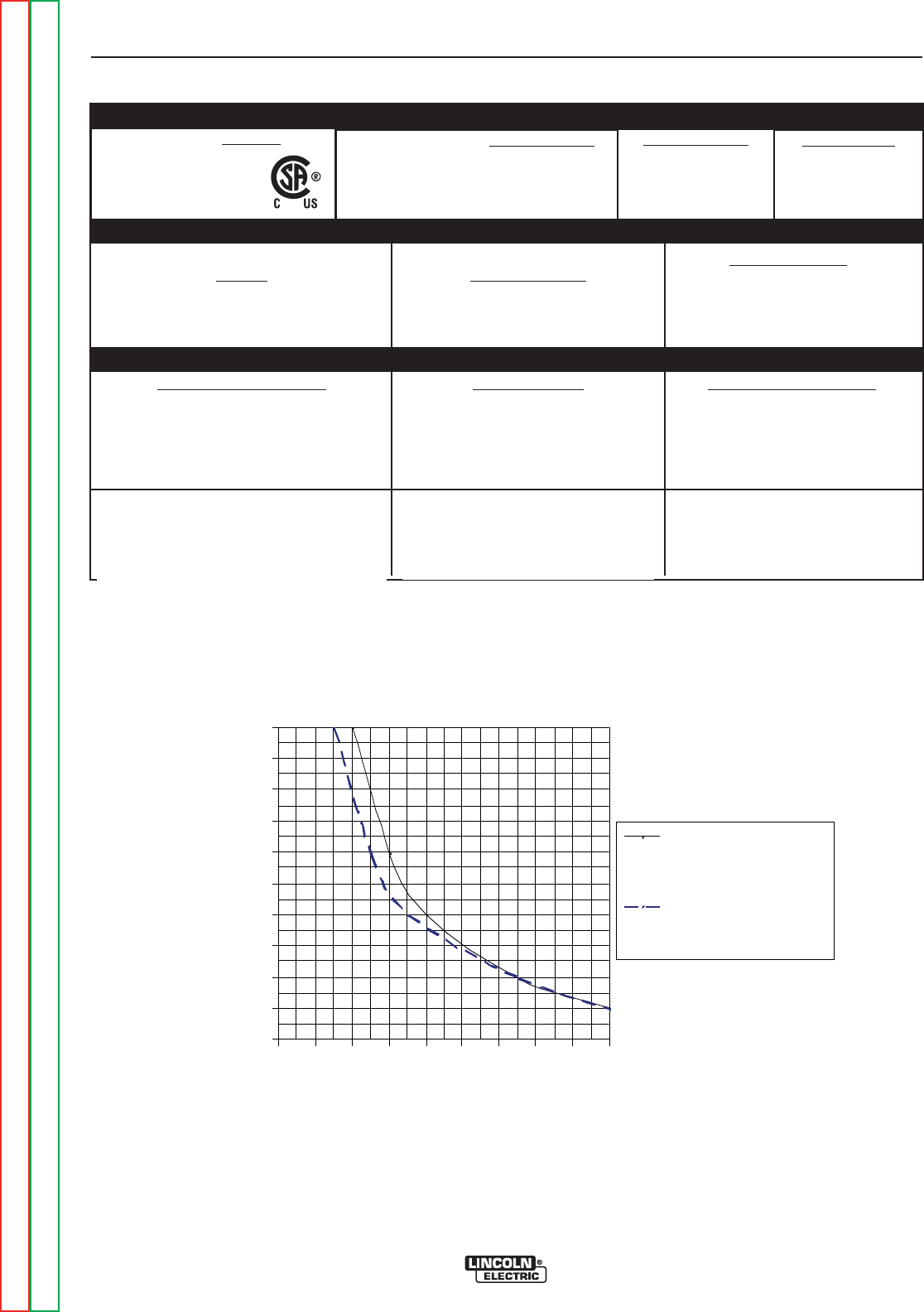
**Chart gives max. rated Output Amps @% Duty Cycle (Based on a 10 minute cycle).
(Example; 180A@20% for AC/DC Stick and TIG)
* Inputs and ratings include a 20 amp rated load on the 115vac receptacle.
AC/DC Stick and Auto-Balance TIG Output Limits
1
Using provided input cable for protected
2
input supply
0%
10%
20%
30%
40%
50%
60%
70%
80%
90%
100%
50 70 90 110 130 150 170 190 210 230
Output Amps
Output Duty Cycle
AC/DC Stick & Bal.TIG
with Max. Aux. load or
Auto-Bal. TIG w/o Aux.
AC Auto-B al. TIG with
Max. Aux. Load
1Output Limits allow for continuous max. rated load on 115vac auxiliary receptacle.
2Wiring and protection based on the 2005 U.S. National Electric Code.
Use a Super Lag type fuse or circuit breaker with a delay in tripping action.
Models with NEMA 6-50P plug may be used with a 50 amp protected 6-50R receptacle, or with a maximum 70 amp protected 6-50R
receptacle if dedicated for the welder.
INSTALLATION
A-3 A-3
PRECISION TIG® 225
Return to Section TOC Return to Section TOC Return to Section TOC Return to Section TOC
Return to Master TOC Return to Master TOC Return to Master TOC Return to Master TOC
TECHNICAL SPECIFICATIONS - CANADIAN (K2533-2), INTERNATIONAL K2534-1)
MODEL HEIGHT WIDTH DEPTH WEIGHT
PHYSICAL DIMENSIONS (2)
Weld Voltage (NEMA)
29.0 V
27.2 V
23.4 V
15.7 V
15.2 V
14.1 V
14.0 v
Output Type
CC (Constant Current)
AC or DC
Weld Current*
225 A AC/DC
180 A AC/DC
90 A AC/DC
225 A AC/DC
180 A AC/DC
90 A AC/DC (Bal.)
80 A AC (Auto-Bal.)
Weld Current
5-230 A (AC)
5-230 A (DC)
Process Duty Cycle**
SMAW
15%
20%
100%
GTAW
10%
20%
100%
Max. OCV.
75 V (AC)
66 V (DC)
OUTPUT RANGE
RATED OUTPUT
ENVIRONMENTAL RANGES
Machine Only
(K2533-1,-2)
(K2534-1)
Ready-Pak
(K2535-1)
Ready-PakW/Cart
(K2535-2)
20.71 in.
526 mm
20.71 in.
526 mm
31.24 in.
794 mm
14.48 in.
368 mm
14.48 in.
368 mm
19.81 in.
503 mm
25.62 in.
751 mm
25.62 in.
651 mm
38.01 in.
966 mm
Approx. 192 lbs.
87.1 kgs
Approx. 212lbs..
96.2 kgs.
Approx. 258lbs.
117.0 kgs.
(2) Dimensions are without Lift Eyebolt and Torch Holder
Power Factor
0.62 Min.
Idle Current
1.3 A/1.0 A Max.
Current
18 A/15 A Effective
42 A/33 A Max.
Voltage/Phase/Freq.
460/575/1/60
K2533-2 INPUT (at Rated Output)
K2534-1 INPUT (at Rated Output)
Power Factor
0.62 Min.
Idle Current
1.5 A/1.4 A Max.
Current
21 A/20 A Effective
50 A/48 A Max.
Voltage/Phase/Freq.
380/400-415/1/50/60
*Inputs and ratings include a 6 amp rated load on the 115vac receptacle.
** Based on a 10 minute cycle.
N80
Operating Temperature -4°F to 104°F (-20°C to 40°C)
Storage Temperature -40°F to 185°F (-40°C to 85°C)
INSTALLATION
A-4 A-4
PRECISION TIG® 225
Return to Section TOC Return to Section TOC Return to Section TOC Return to Section TOC
Return to Master TOC Return to Master TOC Return to Master TOC Return to Master TOC
SAFETY PRECAUTIONS
SELECT SUITABLE LOCATION
MOUNTING
Environmental Rating
The PRECISION TIG® 225 power source carries an
IP21S environmental rating. It may be used in normal
industrial and commercial environments. Avoid using it
in environments which have falling water such as rain.
Read and follow "Electric Shock Warnings" in the
Safety section if welding must be performed under
electrically hazardous conditions such as welding in
wet areas or on or in the workpiece.
• The PRECISION TIG® 225 must be located where
there is free circulation of clean air such that air
movement in and out the back air vents will not be
restricted.
• Dirt and dust that can be drawn into the PRECISION
TIG® 225 should be kept to a minimum. Failure to
observe these precautions can result in excessive
operating temperatures and nuisance shutdown.
GRINDING
Do not direct grinding particles towards the welder. An
abundance of conductive material can cause mainte-
nance problems.
STACKING
PRECISION TIG® 225 cannot be stacked.
LIFTING AND MOVING
The PRECISION TIG® 225 models are provided with
an Eyebolt used for lifting the unit with a hoist.
To install; remove the plug button from the case top
and screw the Eyebolt securely into the threaded
bracket beneath the case top per the below instruc-
tions and warnings provided on the case top decal.
Save the removed plug button (LE part No.T10397-2)
to cover the hole when the lift Eyebolt is removed.
An undercarriage, provided on the Ready-Pak™
w/Cart model, is also available to easily move the unit.
Refer to the Accessories section of this manual.
Do not attempt to lift the power
source with an undercarriage
attached.
The undercarriage is designed for hand moving only;
mechanized movement can lead to personal injury
and/or damage to the PRECISION TIG® 225.
TILTING
Each machine must be placed on a secure, level sur-
face, either directly or on a recommended undercar-
riage. The machine may topple over if this procedure is
not followed.
ELECTRIC SHOCK can kill.
•Only qualified personnel should
perform this installation.
• Turn the input power OFF at the
disconnect switch or fuse box
before working on this equipment.
• Do not touch electrically hot parts.
• Always connect the PRECISION TIG® 225 to a
power supply grounded per the National Electrical
Code and any local codes.
----------------------------------------------------------------------------
WARNING
Read entire installation section before starting
installation.
WARNING

INSTALLATION
A-5 A-5
PRECISION TIG® 225
Return to Section TOC Return to Section TOC Return to Section TOC Return to Section TOC
Return to Master TOC Return to Master TOC Return to Master TOC Return to Master TOC
MACHINE GROUNDING AND HIGH FRE-
QUENCY INTERFERENCE PROTECTION
Locate the Precision TIG® 225 away from radio controlled
machinery. The normal operation of the Precision TIG®
225 may adversely affect the operation of RF controlled
equipment, which may result in bodily injury or damage to
the equipment.
This welder must be grounded! See your local and
national electrical codes for proper grounding meth-
ods.
The high frequency generator, being similar to a radio
transmitter, may cause radio, TV and electronic equip-
ment interference problems. These problems may be the
result of radiated interference. Proper grounding methods
can reduce or eliminate radiated interference.
Radiated interference can develop in the following four
ways:
1. Direct interference radiated from the welder.
2. Direct interference radiated from the welding leads.
3. Direct interference radiated from feedback into the
power lines.
4. Interference from re-radiation of “pickup” by unground-
ed metallic objects.
Keeping these contributing factors in mind, installing
equipment per the following instructions should minimize
problems.
1. Keep the welder power supply lines as short as possi-
ble and enclose as much of them as possible in rigid
metallic conduit or equivalent shielding for a distance of
50 feet (15.2m). There should be good electrical con-
tact between this conduit and the welder case ground.
Both ends of the conduit should be connected to a dri-
ven ground and the entire length should be continuous.
2. Keep the work and electrode leads as short as possi-
ble and as close together as possible. Lengths should
not exceed 25 ft (7.6m). Tape the leads together when
practical.
3. Be sure the torch and work cable rubber coverings are
free of cuts and cracks that allow high frequency leak-
age.
4. Keep the torch in good repair and all connections tight
to reduce high frequency leakage.
5. The work piece must be connected to an earth ground
close to the work clamp, using one of the following
methods:
a) A metal underground water pipe in direct contact with
the earth for ten feet or more.
b) A 3/4” (19mm) galvanized pipe or a 5/8” (16mm)solid
galvanized iron, steel or copper rod driven at least
eight feet into the ground.
The ground should be securely made and the ground-
ing cable should be as short as possible using cable of
the same size as the work cable, or larger. Grounding
to the building frame electrical conduit or along pipe
system can result in re-radiation, effectively making
these members radiating antennas.
6. Keep covers and all screws securely in place.
7. Electrical conductors within 50 ft (15.2m) of the welder
should be enclosed in grounded rigid metallic conduit
or equivalent shielding, wherever possible. Flexible
metallic conduit is generally not suitable.
8. When the welder is enclosed in a metal building,the
metal building should be connected to several good
earth driven electrical grounds (as in 5 (b) above)
around the periphery of the building.
Failure to observe these recommended installation proce-
dures can cause radio or TV and electronic equipment
interference problems and result in unsatisfactory welding
performance resulting from lost high frequency power.
INPUT AND GROUNDING CONNECTIONS
Only a qualified electrician should connect the PRECI-
SION TIG® 225. Installation should be made in accor-
dance with the appropriate National Electrical Code, all
local codes and the information in this manual.
Be sure the voltage, phase, and frequency of the input
power is as specified on the rating plate, located on the
rear of the machine.
208/230 volt models have a NEMA 6-50P plug attached to
the #6-3 input power cord and a NEMA 6 -50R receptacle
is included with the Ready-Pak™ models. Other voltage
models have an #12-3 input power cord but no plug or
receptacle.
Have a qualified electrician provide input power supply to
the receptacle or cord in accordance with all local and
national electrical codes. Use a single phase line or one
phase of a two or three phase line. Choose an input and
grounding wire size according to local or national codes.
Refer to the Technical Specifications page at the begin-
ning of this section. Fuse the input circuit with the recom-
mended super lag fuses or delay type1circuit breakers.
Using fuses or circuit breakers smaller than recommend-
ed may result in “nuisance” shut-offs from welder inrush
currents even if not welding at high currents.
1Also called “inverse time” or “thermal/magnetic” circuit breakers;
circuit breakers which have a delay in tripping action that decreases
as the magnitude of the current increases.
INSTALLATION
A-6 A-6
PRECISION TIG® 225
Return to Section TOC Return to Section TOC Return to Section TOC Return to Section TOC
Return to Master TOC Return to Master TOC Return to Master TOC Return to Master TOC
INPUT RECONNECT PROCEDURE
On multiple input voltage welders, be sure the machine
is connected per the following instructions for the volt-
age being supplied to the welder.
Failure to follow these instructions can cause
immediate failure of components within the welder
and void machineʼs warranty.
-----------------------------------------------------------------------
Multiple voltage models are shipped connected for
the highest voltage. To change this connection
refer to the following instructions.
ELECTRIC SHOCK can kill.
• Turn the input power OFF at the dis-
connect switch or fuse box before
working on this equipment.
------------------------------------------------------------------------
For the lowest rated voltage connection (Refer to figure A.1):
1. Remove the sheet metal left side cover.
2. Disconnect lead H3 from the power switch and insu-
late with the insulation from the H2 lead.
3. Connect lead H2 to the power switch where H3 was
connected.
4. Tighten connections.
5. Replace sheet metal cover and all screws
For the highest rated voltage connection (Refer to Figure A.1):
The machine is normally shipped connected for the
highest rated voltage, however verify the following:
1. Remove the sheet metal left side cover.
2. Disconnect lead H2 from the power switch and insu-
late with the insulation from the H3 lead.
3. Connect lead H3 to the line switch where H2 was
connected.
4. Tighten connections.
5. Replace sheet metal cover and all screws.
CONNECTIONS FOR TIG (GTAW) WELDING
TIG TORCH CONNECTION
Refer to Included Equipment in the Operation
Section of this manual for TIG welding equipment
which is included with the PRECISION TIG® 225.
CAUTION
WARNING
FIGURE A.1 Reconnect Leads
INPUT LEADSINPUT LEADS
L1 & L2L1 & L2
LEAD H1LEAD H1
(DO NOT(DO NOT
REMOVE)REMOVE)
FOR LOWEST RATED VOLTAGEFOR LOWEST RATED VOLTAGE
: H2 CONNECTED : H2 CONNECTED
FOR HIGHEST RATED VOLTAGEFOR HIGHEST RATED VOLTAGE
: H3 CONNECTED : H3 CONNECTED
BACK VIEW OF LINE SWITCHBACK VIEW OF LINE SWITCH
OUTPUT CONNECTIONS
FIGURE A.2 Location of Output Connections
ELECTRODE/GAS
OUTLET
RECEPTACLE
(TWIST-MATE)
WORK CABLE & CLAMP

INSTALLATION
A-7 A-7
PRECISION TIG® 225
Return to Section TOC Return to Section TOC Return to Section TOC Return to Section TOC
Return to Master TOC Return to Master TOC Return to Master TOC Return to Master TOC
CONNECTIONS FOR TIG (GTAW) WELDING
TIG TORCH CONNECTION
A PTA-17 Twist-Mate TIG welding torch with cable and
connector is supplied with the Ready-Pak Models and
available for other models (See Accessories
Section). Turn the Power Switch “OFF”. Connect the
torch cable Twist-Mate quick connect plug into the
Electrode/Gas Output Receptacle on the front of the
welder and turn it clockwise until it is tight. This is a
Twist-Mate quick connect terminal and also provides
the gas connection for the shielding gas to the torch.
To avoid receiving a high frequency shock, keep
the TIG torch and cables in good condition.
------------------------------------------------------------------------
WORK CABLE CONNECTION
A work cable with attached work clamp is factory con-
nected to the PRECISION TIG® 225. To minimize high
frequency interference, refer to Input and Ground
and High Frequency Interference Protection section
of this manual for the proper procedure on grounding
the work clamp and work piece.
SHIELDING GAS CONNECTION
An adjustable gas pressure regulator with flow gage
and hose is supplied with the PRECISION TIG® 225
Ready-Pak™ models and available separately for
other models (See Accessories Section). Obtain the
necessary inert shielding gas (usually argon). Connect
the cylinder of gas with the pressure regulator and flow
gage. Install the gas hose between the regulator and
gas inlet (located on the rear of the welder). The gas
inlet has a 5/16-18 right hand female thread;
CGA#032.
The available Under-Storage Cart features a low plat-
form that simplifies loading and unloading of gas cylin-
ders.
CYLINDER could explode
if damaged.
• Keep cylinder upright and chained
to a support.
• Keep cylinder away from areas
where it could be damaged.
• Never allow the torch to touch the cylinder.
• Keep cylinder away from live electrical circuits.
• Maximum inlet pressure 150 psi.
------------------------------------------------------------------------
A cylinder is loaded by leaning it slightly sideways and
rocking it up on the platform, being careful not to allow
the Under-Storage Cart to roll. Secure the cylinder in
place with the provided chain. Unload by following
these steps in reverse.
REMOTE CONTROL CONNECTION
A remote control receptacle is provided on the case
front of the welder for connecting a remote control to to
the machine. A Foot Amptrol™, foot activated remote
control, is included with the PRECISION TIG® 225
Ready-Pak™ models and available separately for
other models. Refer to the Optional Accessories
Section of this manual for other available remote con-
trols.
CONNECTIONS FOR STICK (SMAW)
WELDING
STICK ELECTRODE CABLE AND WORK CABLE
CONNECTION
Refer to Field Installed Options in the Accessories
Section of this manual for STICK welding equipment
which is available for use with the PRECISION TIG®
225. An electrode holder with Twist-Mate™ cable and
Twist-Mate™ connector are available separately for
use with the PRECISION TIG® 225. (See
Accessories Section). Turn the Power Switch
“OFF”. Connect the Twist-Mate™ quick connect plug
into the Electrode/Gas Output Receptacle and turn it
clockwise until it is tight. The work cable and work
clamp are factory connected.
WARNING
WARNING


TABLE OF CONTENTS - OPERATION SECTION
B-1 B-1
Return to Master TOC Return to Master TOC Return to Master TOC Return to Master TOC
PRECISION TIG® 225
Operation..............................................................................B-1
SafetyPrecautions ....................................................................B-2
GraphicSymbols .....................................................................B-2
ProductDescription ...................................................................B-3
RecommendedProcessesandEquipment .................................................B-3
RecommendedProcesses ..............................................................B-3
ProcessLimitations ...................................................................B-3
RecommendedEquipment/Interface ......................................................B-3
EquipmentLimitation ..................................................................B-3
WeldingCapability ....................................................................B-3
Controls and Settings . . . . . . . . . . . . . . . . . . . . ..........................................B-4,B-5
Power-UpSequence ..................................................................B-5
CaseRearComponents................................................................B-6
OperatingSteps ......................................................................B-7
WeldinginTIGMode ..................................................................B-7
PulseTIGMode ......................................................................B-7
RemoteControlOperation ..............................................................B-8
BenefitsofthePRECISIONTIG®225.....................................................B-8
WeldinginStickMode .................................................................B-9
Recommended Electrode Amperage Ranges ...............................................B-9
OPERATION
B-2 B-2
PRECISION TIG® 225
Return to Section TOC Return to Section TOC Return to Section TOC Return to Section TOC
Return to Master TOC Return to Master TOC Return to Master TOC Return to Master TOC
ELECTRIC SHOCK
can kill.
• Do not touch electrically live parts
or electrode with skin or wet cloth-
ing.
•
Insulate yourself from work and
ground.
• Always wear dry insulating gloves.
•
Read and follow “Electric Shock Warnings” in the
Safety section if welding must be performed under
electrically hazardous conditions such as welding in
wet areas or on or in the workpiece.
--------------------------------------------------------------------------------
FUMES AND GASES
can be dangerous.
• Keep your head out of fumes.
• Use ventilation or exhaust at the
arc, or both, to remove fumes and
gases from breathing zone and
general area.
------------------------------------------------------------------------
WELDING SPARKS can cause fire or
explosion
• Keep flammable material away.
• Do not weld on containers that
have held combustibles.
------------------------------------------------------------------------
ARC RAYS can burn.
• Wear eye, ear and body
protection.
------------------------------------------------------------------------
SAFETY PRECAUTIONS
Read and understand this entire section before operat-
ing the machine.
Observe additional Safety Guidelines detailed in
the beginning of this manual.
------------------------------------------------------------------------
WARNING
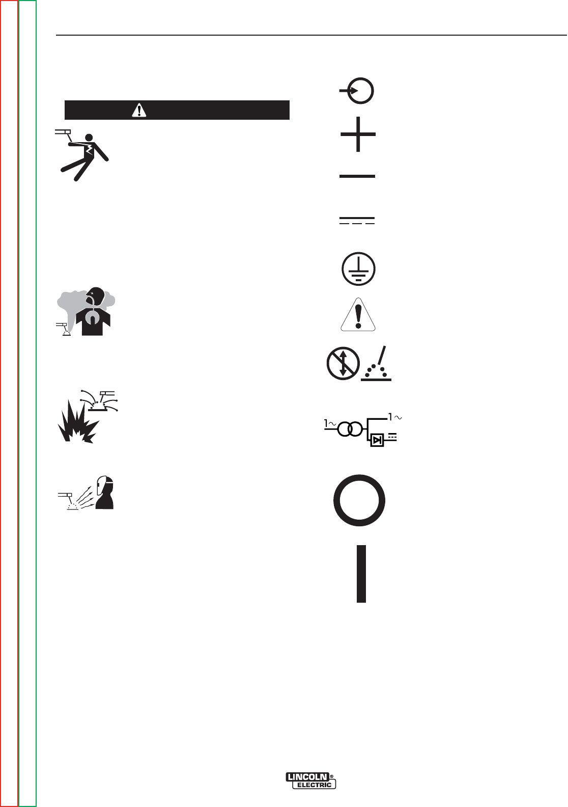
INPUT POWER
POSITIVE OUTPUT
NEGATIVE OUTPUT
DIRECT CURRENT
PROTECTIVE
GROUND
WARNING OR
CAUTION
DO NOT SWITCH
WHILE WELDING
GRAPHIC SYMBOLS THAT APPEAR ON
T
HIS MACHINE OR IN THIS MANUAL
SINGLE PHASE
TRANSFORMER AC AND
RECTIFIER DC POWER
SOURCE
OFF
ON
OPERATION
B-3 B-3
PRECISION TIG® 225
Return to Section TOC Return to Section TOC Return to Section TOC Return to Section TOC
Return to Master TOC Return to Master TOC Return to Master TOC Return to Master TOC
PRODUCT DESCRIPTION
The PRECISION TIG® 225 is a member of our field
acclaimed PRECISION TIG® family of industrial arc welding
power sources. Premium features include:
1. Precise constant current output.
2. Full range square wave AC/DC TIG (GTAW) welding.
3. Enhanced version of the patented Micro-Start II™
Technology for its lower Minimum(5 amps) to higher
Maximum (230 amps) output control range.
4. Built-in high frequency stabilization for DC TIG starting
and continuous AC TIG welding.
5. AC/DC Stick (SMAW capability.) A new undercarriage
(with gas bottle rack) is available for field installation, or is
included with an available Ready-Pak TIG Welding
Package. The PRECISION TIG® patented convenient
built-in storage provisions for welding components and
cable management.
The PRECISION TIG® 225 also provides advanced features
such as:
• Digital Meter
• Presettable control, adjustable Auto Balance™
• Fan As Needed (F.A.N.)
• Timers for fixed Preflow and variable Postflow shielding
gas.
• Built-in, easy to set single knob Pulse TIG control with a
"blinking" light to indicate the pulse frequency setting.
• Auto-Sense remote control selection.
• Tool-less Twist-Mate™ electrode cable connection.
• Built-in work clamp cable permanently attached.
Four models are available for 60Hz. with Domestic and
Canadian input voltages, as well as an International model
with 50/60Hz voltages.
An Auxiliary 115vac Receptacle with Circuit Breaker are
included on the back panel of the PRECISION TIG® 225
models. The Canadian (K2533-2) and International (K2534-
1) models are rated 6 amps, while the 208/230/1/60 models
(K2533-1 and K2535-1/-2) are rated 20 amps (for use with
Lincoln’s 115v SP and Power MIG models).
RECOMMENDED PROCESSES AND EQUIP-
MENT
RECOMMENDED PROCESSES
The PRECISION TIG® 225 is recommended for the TIG
(GTAW) and Stick (SMAW) welding processes within its out-
put capacity range of 5 amps DC or AC to 225 amps AC/DC.
It is compatible with most Magnum TIG accessories, as well
as many industry standard items, such as TIG torches
(adapted for Twist-Mate™), hoses, and water coolers.
PROCESS LIMITATIONS
The PRECISION TIG® machines are not recommended for
arc gouging due to its limited output capacity, and are also
not recommended for pipe thawing.
RECOMMENDED EQUIPMENT/INTERFACE
(See Installed Options in Accessories Section for
more details)
The PRECISION TIG® 225 will be available as a basic
Machine (Only) and in two Factory-Configured Welding
Packages:
1. Machine(Only) (K2345-1)
2. Ready-Pak (K2347-1)
3. Ready-Pak w/Cart (K2347-2)
Basic module will also be available with Domestic, Canadian
and International input voltages for user configuration, with
optional accessories.
Select Machine 208/230/1/60 Machine with NEMA 6-50P
Plug Cable and Receptacle (K2533-1)
460/575/1/60 Machine only with cable (K2533-2)
380/400/415/1/50/60 Machine only
with cable (K2534-1)
Torch Starter Kit Air Cooled System: Water Cooled System:
(Select one) TIG-Mate TIG-Mate 20
Torch Starter Kit* Torch Starter Kit*
Water Cooler Not Applicable 115V 50/60Hz
Cool-Arc 40*
Under-Storage K2348-(*)
Cart (Optional )
Optional Remote Arc Start Switch*
Trigger Device Foot Amptrol*
(Select one) Start Pedal Foot Amptrol*
Hand Amptrol*
*For “Part Numbers” or “K Numbers” see Accessories Section.
EQUIPMENT LIMITATIONS
The PRECISION TIG® machines are protected from over loads
beyond the output ratings and duty cycles, per the Specifications
in the Installation Section, with Thermostat protection of the out-
put power coils and rectifiers.
The PRECISION TIG® 225 machine uses Twist-Mate™ output
terminals, therefore stud connection adapters (such as LECO.
S19257-series) cannot be used for torch connection.
If a PRECISION TIG® 225 is powered from an engine generator
which doesn’t have sufficient capacity, the AC Balance control
and the Output control will not provide full range of control.
WELDING CAPABILITY(Duty Cycle)
The PRECISION TIG® 225 is rated at 225 amps, 29 volts, at
10% duty cycle on a ten minute basis. It is capable of higher duty
cycles at lower output currents. See rated output graph,on
specification sheet located in the Installation Section. If the duty
cycle is exceeded, a thermal protector will shut off the output
until the machine cools.
OPERATION
B-4 B-4
PRECISION TIG® 225
Return to Section TOC Return to Section TOC Return to Section TOC Return to Section TOC
Return to Master TOC Return to Master TOC Return to Master TOC Return to Master TOC
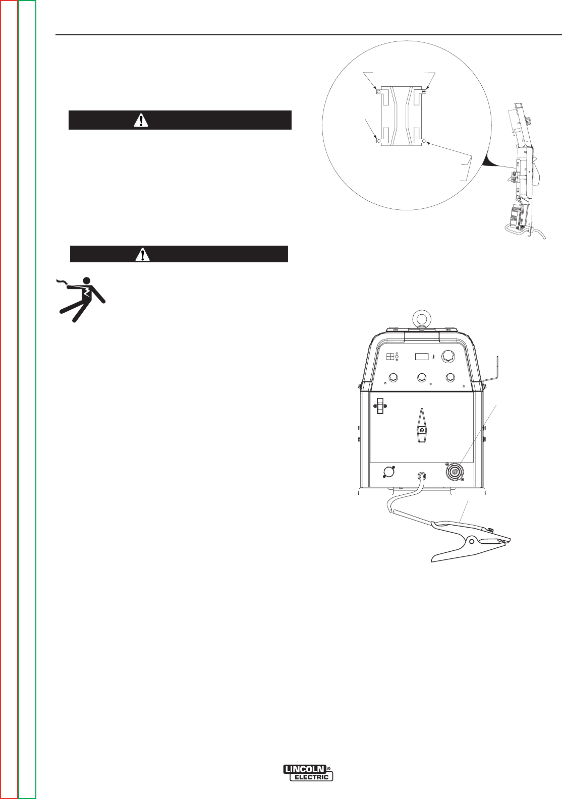
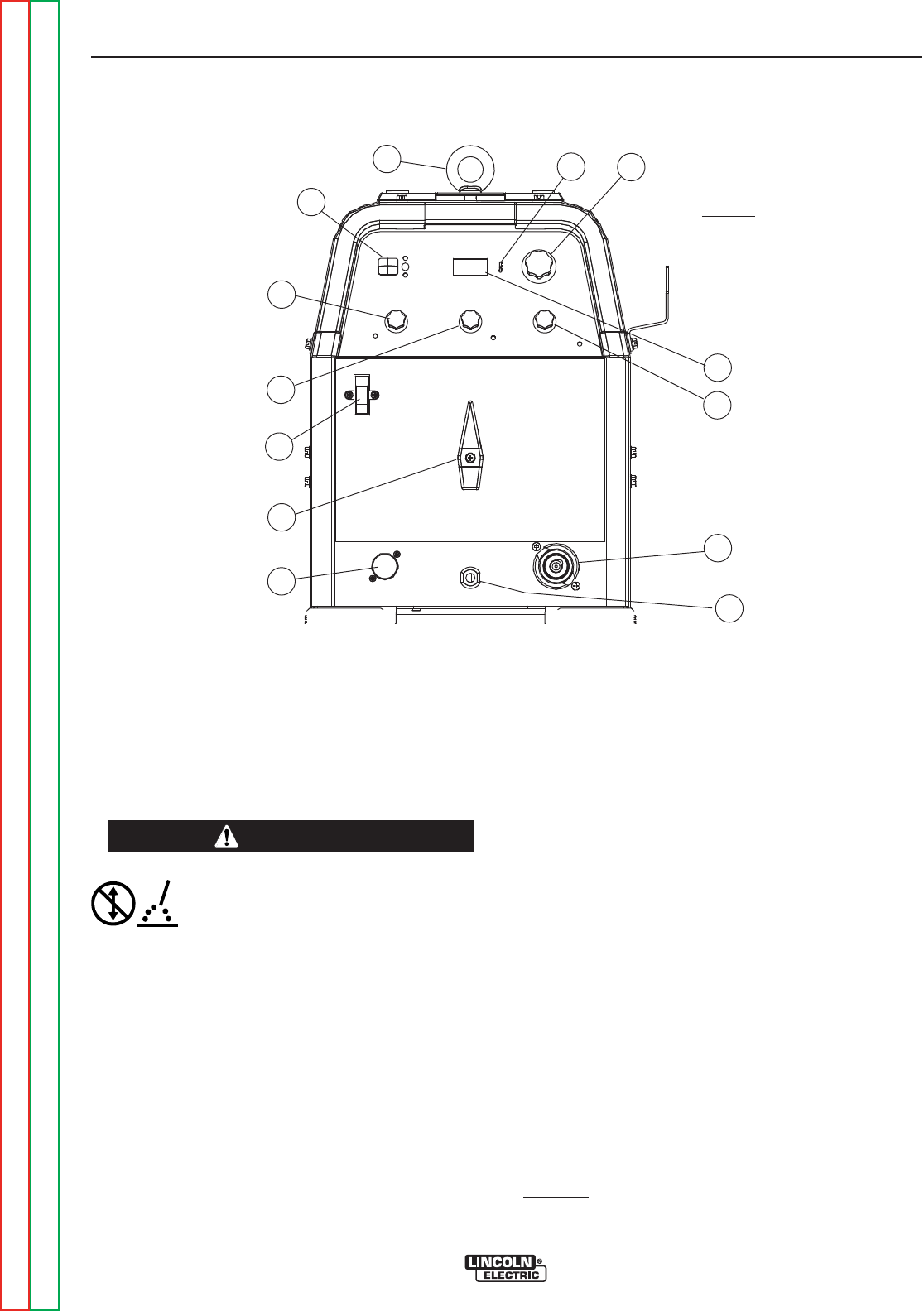
CONTROL FUNCTIONALITY
1. POWER SWITCH – Input line switch turns input
power ON or OFF, as indicated by the on or off sta-
tus of the front panel digital display (See Item 6, also
see the following page for Power-Up Sequence).
2. POLARITY SWITCH – The rotary power switch has
3-positions for DC+, AC and DC- selections for the
electrode output stud welding polarity.
• Do not switch the polarity switch
while welding or damage may result
to the machine.
------------------------------------------------------------------------
3. MODE SWITCH – The push button switch allows
selection of the two machine welding modes as indi-
cated by colored mode lights:
•STICK mode – Top position Red light.
•TIG mode – Bottom position Green light.
4. AC BALANCE CONTROL – The potentiometer
control permits AC TIG wave balance adjustment
from Max. Penetration (~80% negative wave) at full
CW rotation setting, to CCW rotation Max. Cleaning
(~60% positive wave), and includes:
•Auto Balance position indicated by the Green panel
light turning on. This feature automatically provides
the proper amount of cleaning and penetration for
normal AC TIG welding.
5. MAXIMUM OUTPUT CONTROL – Presets the out-
put welding current over the rated output range of
the machine:
• With a Remote Current Control (Amptrol) connect-
ed to the Remote Receptacle (See item 10), this
knob sets the Maximum output current level set
table with the remote Amptrol.
•For Pulse TIG (See Item 8) this knob sets the
Peak Pulse level, with the Remote Amptrol (if
used).
6. DIGITAL METER – A 3 digit LED meter is used to
display the preset output current level before weld-
ing, and actual output level while welding:
• A lit display indicates input power is turned on.
(See Item 1).
7. POST FLOW TIME – Sets the TIG mode shielding
gas post flow time over the range of about 1 to 30
seconds after the arc is shut off.
Note: Gas preflow time is fixed at 0.5 second only in
TIG mode, but no preflow time will occur if the arc is
restarted during Post Flow time, since shielding gas
would not have stopped flowing.
CONTROLS AND SETTINGS
All operator controls and adjustments are located on the front of the PRECISION TIG 225. Refer to Figure B.1
and corresponding explanations.
FIGURE B.1 - CONTROL PANEL
1. POWER SWITCH
2. POLARITY SWITCH
3. MODE SWITCH
4. AC BALANCE CONTROL
5. MAXIMUM OUTPUT CONTROL (AMPS)
6. DIGITAL METERS
7. POST FLOW TIME
8. PULSE TIG CONTROL
9. THERMAL SHUTDOWN LIGHT
10. REMOTE RECEPTACLE
11. ELECTRODE/GAS OUTPUT
RECEPTACLE
12. WORK CABLE
13. REMOVABLE LIFT EYEBOLT
5
13
2
6
3
4
1
7
9
10
11
12
8
CAUTION

OPERATION
B-5 B-5
PRECISION TIG® 225
Return to Section TOC Return to Section TOC Return to Section TOC Return to Section TOC
Return to Master TOC Return to Master TOC Return to Master TOC Return to Master TOC
8. PULSE TIG CONTROL – The Pulse TIG feature
built into the PRECISION TIG® 225 is simplified to
be a single knob control which sets the Pulse
Frequency over the peak pulses/sec. range of about
0.1 to 20 pulses per second:
• Full CCW (min.) setting of the control knob shuts
off Pulse TIG (0.0 pps).
• Peak Pulse level is set by the Max. Output
Control and the Remote Amptrol (if used).
• Background Current level is typically optimized at
a fixed 50% of Peak Pulse level setting.
• Peak Pulse % On-time is typically optimized at a
fixed 50%.
A Green light "blinks" with each Peak Pulse to indi-
cate the Pulse TIG Control setting before and dur-
ing welding.
9. THERMAL SHUTDOWN LIGHT This Yellow LED
panel light turns on if the machine output is shut-
down because internal overheating has occurred,
and turns off when cooled to reset.
10. REMOTE RECEPTACLE – Provides for connec-
tion of remote control and/or arc start switch only in
TIG Mode: (There is no remote output control
capability when stick welding).
• Plugging a remote current control (Amptrol) into
this receptacle automatically switches the output
control from the panel Max Output Control (See
Item 5) to the remote control.
• The connected remote control will then control the
output current between the Min. range of the
machine and the setting of the panel Max Output
Control.
• Switching Mode Switch (See Item 3)toStickwill
automatically disable the connected remote con-
trol and switch the output control back to the Max
Output panel control.
11. ELECTRODE/GAS OUTPUT RECEPTACLE -
This quick connect Twist-Mate™ receptacle pro-
vides electrical connection to the electrode holder
and cable for Stick welding and a combined electri-
cal and gas connection for the TIG torch when TIG
welding.
12. WORK CABLE - This 10ft.(3.05m) cable with work
clamp is factory connected to the welder and its
clamp is connected to the work piece to complete
the welding circuit. Refer to Machine Grounding
and High Frequency Interference Protection in
the Installation section of this manual for the prop-
er procedure on grounding the work clamp and
work piece to minimize high frequency interfer-
ence.
POWER-UP SEQUENCE
When the PRECISION TIG® 225 Power switch is ini-
tially turned On , the following will be observed:
(Refer to this Section Controls and Settings Figure
B.1)
• The cooling fan will run for about 5 seconds.
• The previous (prior to Power Off) settings of Mode
and Maximum Output will be initiated.
• If in TIG Mode, the shielding gas solenoid valve will
be activated for the time set by the Post Flow Time
control.
OPERATION
B-6 B-6
PRECISION TIG® 225
Return to Section TOC Return to Section TOC Return to Section TOC Return to Section TOC
Return to Master TOC Return to Master TOC Return to Master TOC Return to Master TOC
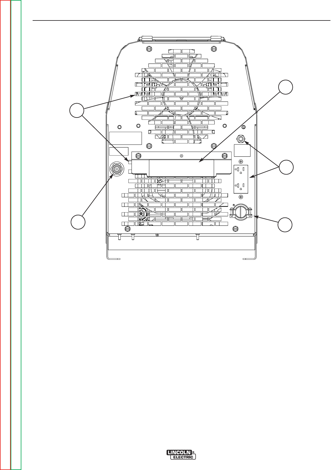
CASE REAR COMPONENTS
1. INPUT CABLE– This #6-3 (208/230V) or #12-3
(380V and higher) heavy duty cable with cable
clamp is factory installed on all models. The
Domestic models (208/230V) also are equipped with
a NEMA 6-50P plug.
2. GAS INPUT CONNECTOR – This is a 5/8-18 right-
hand thread female fitting for connection of input gas
supply.
3. COOLING AIR VENTS – Air is drawn in through the
upper vents and exhausted out through the lower
vents. The louver baffle steers exhaust air down and
prevents it from re-entering the upper vents.
4. MACHINE RATING PLATE
5. RECEPTACLE AND CIRCUIT BREAKER-115vac
auxiliary NEMA 6-20R .
FIGURE B.2
1
5
4
2
3

OPERATION
B-7 B-7
PRECISION TIG® 225
Return to Section TOC Return to Section TOC Return to Section TOC Return to Section TOC
Return to Master TOC Return to Master TOC Return to Master TOC Return to Master TOC
OPERATING STEPS
WELDING IN TIG MODE
1. Connect the TIG torch and cable Twist-Mate™ quick
connect plug to the Electrode/Gas output recepta-
cle. This receptacle also contains an integral gas
connection for the torch. Connect the work clamp to
the work piece.
2. Set the TIG/STICK switch to “TIG”.
3. Set the Polarity Switch to DC- for welding steel or
stainless steel; or to AC for welding aluminum.
4. Connect the Foot Amptrol to the Remote Control
Connector.
5. Turn on the cylinder gas valve and adjust the flow
regulator to obtain desired flow.
6. Turn the power switch to “ON”. NOTE: There will be
a 15 second gas flow when the power is turned on.
7. Preset the Output Control on the control panel to the
maximum desired amps, as read on the digital
meter.
8. Depress the Foot Amptrol to energize the torch and
establish an an arc with the work piece. The digital
meter reads the actual amps while welding.
NOTE: When the TIG/STICK switch is set to “TIG”,
depressing the remote control will start a 0.5
second gas pre-flow before energizing the TIG
torch. When the remote control is released the
TIG torch is de-energized and gas flow will con-
tinue for the time set by the Post Flow Time
control. When the polarity switch is set to DC,
the TIG Arc Starter will turn on and off auto-
matically to start and stabilize the arc. In AC the
TIG Arc Starter will turn on with the output and
remain on continuously until the remote control
is released.
PULSE TIG CONTROL
Use this knob to set the frequency or the number of
pulses per second(pps), from 0.1pps to 20pps.
• This setting adjusts heat output and bead shape for
travel speed. Thinner plate that is welded with faster
travel speed will require higher frequency than thick-
er plate with slower travel speed. 2-3pps is a typical
starting point.

OPERATION
B-8 B-8
PRECISION TIG® 225
Return to Section TOC Return to Section TOC Return to Section TOC Return to Section TOC
Return to Master TOC Return to Master TOC Return to Master TOC Return to Master TOC
REMOTE CONTROL OPERATION
A Foot Amptrol is included with the PRECISION TIG®
225 Ready-Pak models and available for other models
(See Accessories Section) for remote current control
while TIG welding. An optional Hand Amptrol may also
be used. An optional Arc Start Switch may be used to
start and stop the welding if no remote control of the
current is desired. Refer to the Accessories Section
of this manual.
Both the Hand and Foot Amptrol work in a similar man-
ner. For simplicity, the following explanation will refer
only to “Amptrols”, meaning both Foot and Hand mod-
els. The term “minimum” refers to a foot pedal in the
“up” position, as it would be with no foot pressure, or a
Hand Amptrol in the relaxed position, with no thumb
pressure.
“Maximum” refers to a fully depressed Foot Amptrol,or
a fully extended Hand Amptrol.
When the welder is in TIG modes activating the
Amptrol energizes the electrode terminal and varies
the output welding current from its minimum value of 5
Amp (DC) or (AC), to the maximum value set by the
Current Control on the control panel. This helps elimi-
nate accidental high current damage to the work piece
and/or tungsten, and provides a fine control of the cur-
rent. When the welder is in the stick mode a remote
control has no effect and is not used.
It is important to note that, in some cases, the tungsten
will not start an arc at the minimum current because
the tungsten may be too large or cold. To start an arc
reliably, it is important to depress the Amptrol far
enough so that the machine output current is near the
tungsten operating range. For example, a 3/32” tung-
sten may be used on DC- to weld over the full range of
the machine.
To start the arc, the operator may have to turn the cur-
rent control up and depress the Amptrol approximately
1/4 of the way down. Depressing the Amptrol to its min-
imum position may not start the arc. Also if the current
control is set too low, the arc may not start. In most
cases, a large or cold tungsten will not readily establish
an arc at low currents. This is normal. In Direct Current
mode the PRECISION TIG® 225 will start a 3/32”, 2%
thoriated tungsten electrode at 15 amperes provided
the electrode tip is properly grounded and not contam-
inated.
BENEFITS OF THE PRECISION TIG® 225 DESIGN
In AC TIG welding of aluminum, the positive portion of
the AC wave provides cleaning (removal of aluminum
oxide) of the work piece. This is desirable on materials
with a heavy oxide coating. However the positive por-
tion may also cause the electrode to overheat at high
currents causing “tungsten spitting”. The negative por-
tion of the AC wave offers no cleaning action but con-
centrates more heat on the work.
The AC waveform of the PRECISION TIG® 225 opti-
mizes cleaning and heating of the work. The result is
the capability to weld through the complete range in AC
TIG or DC- TIG requiring only one electrode, a 3/32”
2% thoriated tungsten.
OPERATION
B-9 B-9
PRECISION TIG® 225
Return to Section TOC Return to Section TOC Return to Section TOC Return to Section TOC
Return to Master TOC Return to Master TOC Return to Master TOC Return to Master TOC
WELDING IN STICK MODE
1. Put the electrode holder and cable quick connect
plug into the electrode output receptacle. Turn clock-
wise until tight. Connect the work clamp to the work
piece.
2. Set the TIG/STICK switch to “STICK”.
3. Set the Polarity Switch to the weld mode desired for
the type of electrode being used (most commonly
DC+).
4. Place the electrode in the electrode holder.
• In Stick Mode the output terminal
and electrode will be electrically hot
whenever the power switch is turned
on.
------------------------------------------------------------------------
5. Turn the power switch to “ON”.
6. Adjust the Current Control to the desired amps.
7. Strike an arc and weld.
NOTE: When the TIG/STICK switch is set to “STICK”
the output is always on when the power switch
is on. A remote control has no effect on the
welding current and the gas flow and high fre-
quency TIG arc starter are disabled.
RECOMMENDED ELECTRODE AMPERAGE RANGES - PRECISION TIG 225
The PRECISION TIG 225 is rated from 5-225 Amps.
SMAW Process
Welding Amp Range for Stick Electrode Size
ELECTRODE TYPE POLARITY 3/32" 1/8" 5/32"
Fleetweld 5P, Fleetweld 5P+ E6010 DC+ 40 - 70 75 - 130 90 - 175
Fleetweld 180 E6011 DC+ 40 - 80 55 - 110 105 - 135
Fleetweld 37 E6013 DC+ 70 - 95 100 - 135 145 - 180
Fleetweld 47 E7014 DC- 75 - 95 100 - 145 135 - 200
Excalibur E7018 DC+ 85 - 110 110 - 160 130 - 200
Blue Max Stainless DC+ 40 - 80 75 - 110 95 - 150
Red Baron Stainless DC+ 40 - 70 60 - 100 90 - 140
Mild steel procedures are based on recommended procedures listed in C2.10 8/94 and the maximum rating of the PRECISION TIG 225
Blue Max procedures are based on C6.1 6/95
Red Baron Procedure are based on ES-503 10/93
GTAW Process
Electrode Polarity DC- AC Approximate Argon
Electrode Tip Preparation Sharpened Balled Gas Flow Rate
Electrode Type EWZr C.F.H. (l/min.)
EWTh-1, EWCe-2 EWTh-1, EWTh-2
EWTh-2, EWLa-1 EWP EWCe-2, EWLa-1 Stainless
Tungsten Size (in.) EWG EWG Aluminum Steel
.010 Up to 15 A. Up to 10 A. Up to 15 A. 3-8 (2-4) 3-8 (2-4)
.020 Up to 15 A. Up to 15 A. Up to 20 A. 5-10 (3-5) 5-10 (3-5)
.040 Up to 80 A. Up to 40 A. Up to 60 A. 5-10 (3-5) 5-10 (3-5)
1/16 Up to 150 A. Up to 100 A. Up to 130 A. 5-10 (3-5) 9-13 (4-6)
3/32 Up to MAX. A. Up to 160 A. Up to MAX. A. 13-17 (6-8) 11-15 (5-7)
1/8 X Up to MAX. A. X 15-23 (7-11) 11-15 (5-7)
Tungsten electrodes are classified as follows by the American Welding Society (AWS):
Pure ..................................EWP........green TRI-MIX OF ELEMENTS.............EWG.........gray
+1% Thoria .......................EWTh-1...yellow
+2% Thoria .......................EWTh-2...red
+2% Ceria.........................EWCe-2...orange
+1.5% Lanthana ...............EWLa-1 ...black
+0.15 to 0.40% Zirconia....EWZr.......brown
Ceriated Tungsten is now widely accepted as a substitute for 2% Thoriated Tungsten in AC and DC applications.
WARNING


TABLE OF CONTENTS - ACCESSORIES SECTION
C-1 C-1
Return to Master TOC Return to Master TOC Return to Master TOC Return to Master TOC
PRECISION TIG® 225
Accessories............................................................................C-1
StandardEquipmentPackages ..........................................................C-2
FactoryInstalledOptions ...............................................................C-3
FieldInstalledOptions .................................................................C-4

ACCESSORIES
C-2 C-2
PRECISION TIG® 225
Return to Section TOC Return to Section TOC Return to Section TOC Return to Section TOC
Return to Master TOC Return to Master TOC Return to Master TOC Return to Master TOC
TABLE C.1
STANDARD EQUIPMENT PACKAGES
The PRECISION TIG® 225 will be available in two
Factory-Configured Welding Packages:
1. PRECISION TIG® 225 Ready-Pak (K2535-1)
• 208/230/1/60 Machine (K2533-1)
• 9 ft. (2.7m) Input Cable with NEMA 6-50P Plug*
• NEMA 6-50R Receptacle
• Integrated 10 ft.(3.1m)Work Lead w/Clamp*
• Gas Regulator with 10 ft.(3.1m). Hose
• PTA-17 12.5”(318mm) Ultra=Flex Torch with
3/32”(2.4mm)Electrode and Parts
• Foot Amptrol (K870)
• TIG Slide Rule ( WC332)*
• GTAW Book (JFLF-834)*
• Lift Eyebolt*
2. PRECISION TIG® 225 Ready-Pak w/Cart (K2535-
2)
• 208/230/1/60 Machine (K2533-1)
• 9 ft.(2.7m) Input Cable with NEMA 6-50P Plug*
• NEMA 6-50R Receptacle
• Integrated 10 ft.(3.1m) Work Lead w/Clamp*
• Gas Regulator with 10 ft.(3.1m) Hose
• PTA-17 12.5 ft.(3.8m) One cable Superflex Torch with
3/32”(2.4mm) Electrode and Parts
• Foot Amptrol (K870)
• TIG Slide Rule (WC332)*
• GTAW Book (JFLF-834)*
• Lift Eyebolt*
• Under-Storage Cart (K2348-1)
* Included with K2533-1 Machine Only model.
Water Cooled System
K2267-1 TIG-Mate 20 Torch Starter Kit
K1813-1 115V 50/60Hz Cool-Arc 40
Select Machine
Optional
Torch Starter Kit
(Select one)
Optional Under-
Storage Cart
Optional Remote
Trigger Device
(Select one)
208/230/1/60 Machine with 9 ft.(2.7m) NEMA 6-50P Plug Cable and Receptacle (K2533-1)
460/575/1/60 Machine only with Cable (K2533-2)
380/400-415/1/50-60 Machine only with Cable (K2534-1)
Water Cooler Not Applicable K1813-1 115V 50/60Hz Cool-Arc 40
Air Cooled System
K2266-1 TIG-Mate Torch Starter
Not Applicable
K2348-1
K814 Arc Start Switch
K870 Foot Amptrol
K963-3 Hand Amptrol
The PRECISION TIG® 225 will also be available as Basic models with Domestic, Canadian and International
input voltages for user-configuration:with optional accessories. (See Table C.1)

ACCESSORIES
C-3 C-3
PRECISION TIG® 225
Return to Section TOC Return to Section TOC Return to Section TOC Return to Section TOC
Return to Master TOC Return to Master TOC Return to Master TOC Return to Master TOC
FACTORY INSTALLED OPTIONS
The PRECISION TIG® 225 will be available in two
Factory-Configured Welding Packages:
1. PRECISION TIG® 225 Ready-Pak (K2535-1)
• 208/230/1/60 Machine (K2533-1)
• 9 ft. (2.7m) Input Cable with NEMA 6-50P Plug*
• NEMA 6-50R Receptacle
• Integrated 10 ft.(3.1m)Work Lead w/Clamp*
• Gas Regulator with 10 ft.(3.1m). Hose
• PTA-17 12.5’ Ultra-Flex Torch (K1782-12) Includes:
- 3/32 2%Th Tungsten
- 3/32 Collet (10N24)
- 3/32 Collet Body (10N32)
- #7 Alumina Nozzle (10N47)
• Foot Amptrol (K870)
• TIG Slide Rule ( WC332)*
• GTAW Book (JFLF-834)*
• Lift Eyebolt*
2. PRECISION TIG® 225 Ready-Pak w/Cart (K2535-
2)
• 208/230/1/60 Machine (K2533-1)
• 9 ft.(2.7m) Input Cable with NEMA 6-50P Plug*
• NEMA 6-50R Receptacle
• Integrated 10 ft.(3.1m) Work Lead w/Clamp*
• Gas Regulator with 10 ft.(3.1m) Hose
• PTA-17 12.5’ Ultra-Flex Torch (K1782-12) Includes:
- 3/32 2%Th Tungsten
- 3/32 Collet (10N24)
- 3/32 Collet Body (10N32)
- #7 Alumina Nozzle (10N47)
• Foot Amptrol (K870)
• TIG Slide Rule (WC332)*
• GTAW Book (JFLF-834)*
• Lift Eyebolt*
• Under-Storage Cart (K2348-1)
* Included with K2533-1 Machine Only model.
Water Cooled System
K2267-1 TIG-Mate 20 Torch Starter Kit
Includes:
• 200A PTW-20 12.5 ft.(3.81m) Torch
• KP510 Parts Kit
• Regulator & Hose
• K1622-4 Twist Mate Torch Adapter
•WaterHose&HoseCoupler
• Work Cable & Clamp (Not required for
PRECISION TIG® 225)
K1813-1 115V 50/60Hz Cool-Arc 40
Select Machine
Optional
Torch Starter Kit
(Select one)
Water Cooler
Optional Under-
Storage Cart
Optional Remote
Trigger Device
(Select one)
208/230/1/60 Machine with 9 ft.(2.7m) NEMA 6-50P Plug Cable and Receptacle (K2533-1)
460/575/1/60 Machine only with Cable (K2533-2)
380/400-415/1/50-60 Machine only with Cable (K2534-1)
Air Cooled System
K2266-1 TIG-Mate Torch Starter
Kit Includes:
• 150A PTA-17 12.5 ft.(3.81m) Torch.
• KP508 Parts Kit.
• Regulator & Hose.
• K1622-1 Twist Mate Torch Adapter.
• Work Cable & Clamp (Not required for PRECI-
SION TIG® 225)
Not Applicable
TABLE C.2
K2348-1
K814 Arc Start Switch
K870 Foot Amptrol
K963-3 Hand Amptrol
The PRECISION TIG® 225 will also be available as Basic models with Domestic, Canadian and International
input voltages for user-configuration with optional accessories: (See Table C.2)

ACCESSORIES
C-4 C-4
PRECISION TIG® 225
Return to Section TOC Return to Section TOC Return to Section TOC Return to Section TOC
Return to Master TOC Return to Master TOC Return to Master TOC Return to Master TOC
FIELD INSTALLED OPTIONS
The following Options/Accessories are available for the
PRECISION TIG® 225:
• K2348-1 Under-Storage Cart
Includes a front magnetic latch storage drawer and
rear storage bin on a single bottle undercarriage.
(L12225 Installation Instructions included)
• K870 Foot Amptrol
Single pedal foot activation of arc start switch and
output control, with 25 ft.(7.6m) plug cable.
• K963-3 Hand Amptrol
Fastens to torch for convenient thumb activation of
arc start switch and output control, with 25 ft.(7.6m)
plug cable:
• K814 Arc Start Switch
Needed for TIG welding without an Amptrol. Includes
25 ft.(7.6m) plug cable, and attaches to torch for con-
venient finger control.
• TIG-Mate Torch Starter Kits:
Includes Torch with Twist-Mate adapter and acces-
sories listed below:
K2266-1 TIG-Mate Torch Starter Kit Includes:
• 150A PTA-17 12.5 ft.(3.8m) Torch
• KP508 Parts Kit
• Regulator & Hose
• K1622-1 Twist Mate Torch Adapter
• Work Cable & Clamp (Not required for PRECISION
TIG® 225)
K2267-1 TIG-Mate 20 Torch Starter Kit Includes:
• 200A PTW-20 12.5 ft.(3.8m) Torch
• KP510 Parts Kit
• Regulator & Hose
• K1622-4 Twist Mate Torch Adapter
• Water Hose & Hose Coupler
•WorkCable&Clamp
(Not required for PRECISION TIG® 225)
• Magnum “Pro-Torch™ TIG Torch” assemblies and
Accessories.
Requires Twist-Mate™ Adapter:
K1622-1 for PTA-9/-17
K1622-3 for PTA-26
K1622-4 for PTW water cooled torch
• Harris #3100211 Harris Argon Flow Regulator
(Includes 10 ft.(3.1m) hose.)
• K2374-1 Electrode Holder and Cable
200 amp Electrode Holder with 10 ft.(3.1m) cable
and Twist-Mate™ connector.

TABLE OF CONTENTS - MAINTENANCE SECTION
D-1 D-1
Return to Master TOC Return to Master TOC Return to Master TOC Return to Master TOC
PRECISION TIG® 225
Maintenance ...........................................................................D-1
SafetyPrecautions ....................................................................D-2
RoutineandPeriodicMaintenance .......................................................D-2
SparkGapAdjustment .................................................................D-2
FanMotororFanBladeReplacement.....................................................D-2
MAINTENANCE
D-2 D-2
PRECISION TIG® 225
Return to Section TOC Return to Section TOC Return to Section TOC Return to Section TOC
Return to Master TOC Return to Master TOC Return to Master TOC Return to Master TOC
SAFETY PRECAUTIONS
ELECTRIC SHOCK can kill.
• Only qualified personnel should per-
form this maintenance.
• Turn the input power OFF at the dis-
connect switch or fuse box before
working on this equipment.
• Do not touch electrically hot parts.
------------------------------------------------------------------------
To avoid receiving a high frequency shock, keep
the TIG torch and cables in good condition.
------------------------------------------------------------------------
ROUTINE AND PERIODIC MAINTENANCE
1. Disconnect power supply lines to machine before
performing periodic maintenance.
2. Periodically clean the inside of the machine with a
low pressure air system. Be sure to clean the fol-
lowing components thoroughly.
• Main Transformer
• Electrode/Gas Output Receptacle
• Polarity Switch
• Rectifier Assembly
• Arc Starter/Spark Gap Assembly
•PCBoards
• Fan Blades
3. Inspect welder output and control cables for fraying,
cuts, and bare spots.
4. Keep TIG torch and cables in good condition.
5. Clean air louvers to ensure proper air flow and cool-
ing.
6. The fan motor has sealed ball bearings which
require no maintenance.
7. SPARK GAP ADJUSTMENT
The spark gap .020(.5mm) is set at the factory to a
gap of 0.015 inches (0.4mm) See Figure D.1. This
setting is adequate for most applications. Where less
high frequency is desired, the setting can be reduced
to 0.015 inches (0.4mm).
Use extreme caution when working with a high fre-
quency circuit. The high voltages developed can
be lethal. Turn the input power off using the dis-
connect switch or fuse box before working inside
machine. This is particularly important when work-
ing on the secondary circuit of the high voltage
transformer (T3) because the output voltage is
dangerously high.
-----------------------------------------------------------------------
Refer to figure D.1. Note in highly dirty environments
where there is an abundance of conductive contami-
nant's, use a low pressure air stream or a firm piece of
paper to clean the spark gap. Do not disturb the facto-
ry setting.
To check the spark gap:
- Turn off input power as specified above.
- Remove the right side panel from the
machine, the spark gap box is located on the
lower right side.
- Check the spark gap with a feeler gauge.
If adjustment is needed:
- Adjust the gap by loosening the allen head
screw in one of the aluminum blocks, near
the front of the unit and tighten the screw in
the new position.
If the gap is correct:
- Replace the wraparound.
8. Inspect gas hose and inlet fitting for cracks or leaks.
9. Replace any unreadable labels or decal's.
10. Verify that the machine and welding circuit is prop-
erly grounded.
FIGURE D.1 SPARK GAP
FAN MOTOR OR FAN BLADE REPLACEMENT
When installing a new fan blade or fan motor be sure
to maintain proper shaft spacing per Figure D.2 below.
WARNING
WARNING
WARNING
.020 Spark Gap
.020 Spark Gap
FIGURE D.2
.30ł
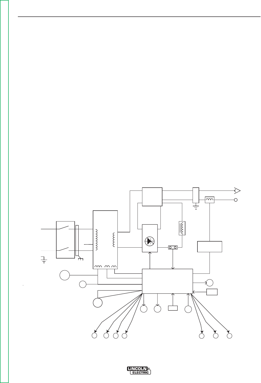
TABLE OF CONTENTS-THEORY OF OPERATION SECTION
E-1 E-1
Return to Master TOC Return to Master TOC Return to Master TOC Return to Master TOC
PRECISION TIG® 225
TheoryofOperation .....................................................................E-1
GeneralDescription ...................................................................E-2
InputPowerCircuit....................................................................E-2
OutputRectificationandFeedbackControl .................................................E-3
HighVoltage/HighFrequencyCircuit ......................................................E-4
DCWeldingOutput ...................................................................E-5
ACWeldingOutput ...................................................................E-6
SCROperation .......................................................................E-7
ProtectiveCircuits ....................................................................E-8
ThermalProtection ....................................................................E-8
OverloadProtection ...................................................................E-8
FIGURE E.1 PRECISION TIG® 225 BLOCK LOGIC DIAGRAM
INPUT
POWER
SWITCH
MAIN
TRANSFORMER
POLARITY
SWITCH
SCR
BRIDGE
X1
X2
AC
AC DC+
DC-
CONTROL
BOARD
18VAC
18VAC
115VAC
FAN
REMOTE
RECEPTACLE
H1
H2
H3
SHUNT
115VAC
HIGH VOLTAGE
TRANSFORMER
CIRCUIT
BY-PASS
BOARD
HI-FREQUENCY
TRANSFORMER
C
H
O
K
E
WORK
ELECTRODE
THERMAL
LIGHT
GAS
VALVE
THERMO-
STATS OUTPUT
CONTROL
MODE
SWITCH
POWER
"ON"
DIGITAL
DISPLAY
F
E
E
D
B
A
C
K
AUTO
BALANCE
LED
TIG
LED
STICK
LED
PULSE
FREQ.
LED
BYPASS
ASBLY
AC
BALANCE
CONTROL
PULSE
CONTROL
POSTFLOW
CONTROL
115 VAC
Receptacle
Circuit Breaker
Protected
THEORY OF OPERATION
E-2 E-2
PRECISION TIG® 225
Return to Section TOC Return to Section TOC Return to Section TOC Return to Section TOC
Return to Master TOC Return to Master TOC Return to Master TOC Return to Master TOC
GENERAL DESCRIPTION
The PRECISION TIG® 225 is a member of our field
acclaimed PRECISION TIG® family of industrial arc
welding power sources. Premium features include:
1. Precise constant current output.
2. Full range square wave AC/DC TIG (GTAW)
welding.
3. Enhanced version of the patented MicroStartTM
Technology for its lower Minimum (5amps) to high-
er Maximum (225 amps) output control range.
4. Built-in high frequency stabilization for DC TIG
starting and continuous AC TIG welding.
5. AC/DC Stick (SMAW capability.)
FIGURE E.2 - General Description & Input Power Circuit
INPUT POWER CIRCUIT
The desired single-phase input power is connected to
the TIG 225 through an input power switch located in
the front panel of the machine. The machine can be
configured for either 230VAC or 208VAC input voltage
by connecting the appropriate lead (H2 or H3) to the
input power switch. When the input power switch is
turned “ON” the input voltage is applied directly to the
primary of the main transformer.
The main transformer changes the high voltage, low
current input power to a low voltage, high current out-
put which is available at the main secondary winding
(X1 and X2). In addition three auxiliary windings are
incorporated in the main transformer. The 115VAC
winding supplies power to the fan motor, the 115 VAC
receptacle, and also, through the control board, pow-
ers the gas solenoid valve and the high voltage trans-
former. The 18VAC winding provides power to the trig-
ger circuitry. The other 18VAC winding is rectified and
regulated to a 15VDC supply which operates the cir-
cuitry on the control board.
NOTE: Unshaded areas of Block Logic
Diagram are the subject of discussion
INPUT
POWER
SWITCH
MAIN
TRANSFORMER
POLARITY
SWITCH
SCR
BRIDGE
X1
X2 AC
AC DC+
DC-
CONTROL
BOARD
18VAC
18VAC
115VAC
FAN
REMOTE
RECEPTACLE
H1
H2
H3
SHUNT
115VAC
HIGH VOLTAGE
TRANSFORMER
CIRCUIT
BY-PASS
BOARD
HI-FREQUENCY
TRANSFORMER
C
H
O
K
E
WORK
ELECTRODE
THERMAL
LIGHT
GAS
VALVE
THERMO-
STATS OUTPUT
CONTROL
MODE
SWITCH
POWER
"ON"
DIGITAL
DISPLAY
F
E
E
D
B
A
C
K
AUTO
BALANCE
LED
TIG
LED
STICK
LED
PULSE
FREQ.
LED
BYPASS
ASBLY
AC
BALANCE
CONTROL
PULSE
CONTROL
POSTFLOW
CONTROL
115 VAC
Receptacle
Circuit Breaker
Protected
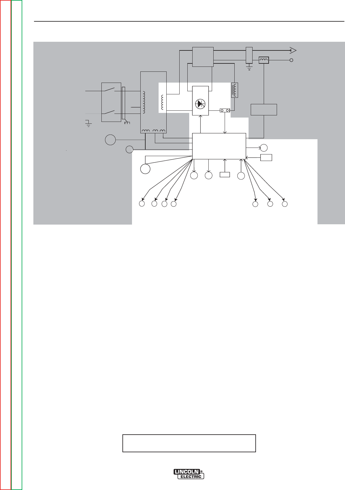
THEORY OF OPERATION
E-3 E-3
PRECISION TIG® 225
Return to Section TOC Return to Section TOC Return to Section TOC Return to Section TOC
Return to Master TOC Return to Master TOC Return to Master TOC Return to Master TOC
OUTPUT RECTIFICATION AND
FEEDBACK CONTROL
The AC output from the main transformer secondary is
rectified and controlled through the SCR bridge.
Output current is sensed at the shunt as a low voltage
signal and fed back to the control board. The control
board compares the commands of the mode switch,
output control, AC balance control, pulse control, post-
flow control, or remote control with the feedback infor-
mation. The appropriate SCR gate firing signals are
created by the control board and sent to the SCR
bridge. The control board controls the firing of the
SCRs, which control the output of the machine. See
SCR Operation. The control board monitors the ther-
mostats, and also controls the gas solenoid valve, ther-
mal light, auto balance LED, pulse frequency LED, TIG
LED, stick LED, and the digital display.
FIGURE E.2 - Output Rectification & Feedback Control
NOTE: Unshaded areas of Block Logic
Diagram are the subject of discussion
INPUT
POWER
SWITCH
MAIN
TRANSFORMER
POLARITY
SWITCH
SCR
BRIDGE
X1
X2
AC
AC DC+
DC-
CONTROL
BOARD
18VAC
18VAC
115VAC
FAN
REMOTE
RECEPTACLE
H1
H2
H3
SHUNT
115VAC
HIGH VOLTAGE
TRANSFORMER
CIRCUIT
BY-PASS
BOARD
HI-FREQUENCY
TRANSFORMER
C
H
O
K
E
WORK
ELECTRODE
THERMAL
LIGHT
GAS
VALVE
THERMO-
STATS OUTPUT
CONTROL
MODE
SWITCH
POWER
"ON"
DIGITAL
DISPLAY
F
E
E
D
B
A
C
K
AUTO
BALANCE
LED
TIG
LED
STICK
LED
PULSE
FREQ.
LED
BYPASS
ASBLY
AC
BALANCE
CONTROL
PULSE
CONTROL
POSTFLOW
CONTROL
115 VAC
Receptacle
Circuit Breaker
Protected
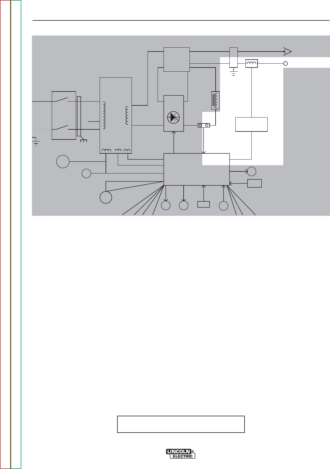
THEORY OF OPERATION
E-4 E-4
PRECISION TIG® 225
Return to Section TOC Return to Section TOC Return to Section TOC Return to Section TOC
Return to Master TOC Return to Master TOC Return to Master TOC Return to Master TOC
HIGH VOLTAGE / HIGH FREQUENCY
CIRCUIT
The control board passes the 115VAC voltage to the
primary of the high voltage transformer. The secondary
of the high voltage transformer is coupled to a spark
gap generator and also to the high frequency trans-
former. The high frequency transformer transfers the
high frequency “spark” to the electrode terminal which
is coupled to the TIG torch.
FIGURE E.2 - High Voltage/High Frequency Circuit.
NOTE: Unshaded areas of Block Logic
Diagram are the subject of discussion
INPUT
POWER
SWITCH
MAIN
TRANSFORMER
POLARITY
SWITCH
SCR
BRIDGE
X1
X2 AC
AC DC+
DC-
CONTROL
BOARD
18VAC
18VAC
115VAC
FAN
REMOTE
RECEPTACLE
H1
H2
H3
SHUNT
115VAC
HIGH VOLTAGE
TRANSFORMER
CIRCUIT
BY-PASS
BOARD
HI-FREQUENCY
TRANSFORMER
C
H
O
K
E
WORK
ELECTRODE
THERMAL GAS THERMO-
STATS
OUTPUT
MODE
SWITCH
POWER
"ON"
DIGITAL
DISPLAY
F
E
E
D
B
A
C
K
BYPASS
ASBLY
115 VAC
Receptacle
Circuit Breaker
Protected
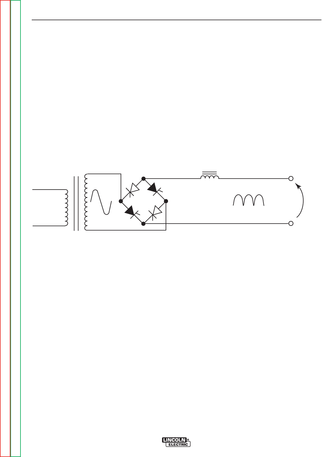
THEORY OF OPERATION
E-5 E-5
PRECISION TIG® 225
Return to Section TOC Return to Section TOC Return to Section TOC Return to Section TOC
Return to Master TOC Return to Master TOC Return to Master TOC Return to Master TOC
DC WELDING OUTPUT
When the polarity switch is placed in either DC position, the AC voltage from the main transformer secondary is
applied to the SCR bridge. The SCR bridge and choke circuits are connected in a conventional full wave bridge
and filter configuration, resulting in a controlled DC output. Since the choke is in series with the negative leg of
the bridge and also in series with the welding load, a filtered DC is applied to the machine output terminals.
FIGURE E.5 DC Welding Current Generation.
CHOKE
WORK
ELECTRODE
PRIMARY
1Ø
G
G
G
G
DC
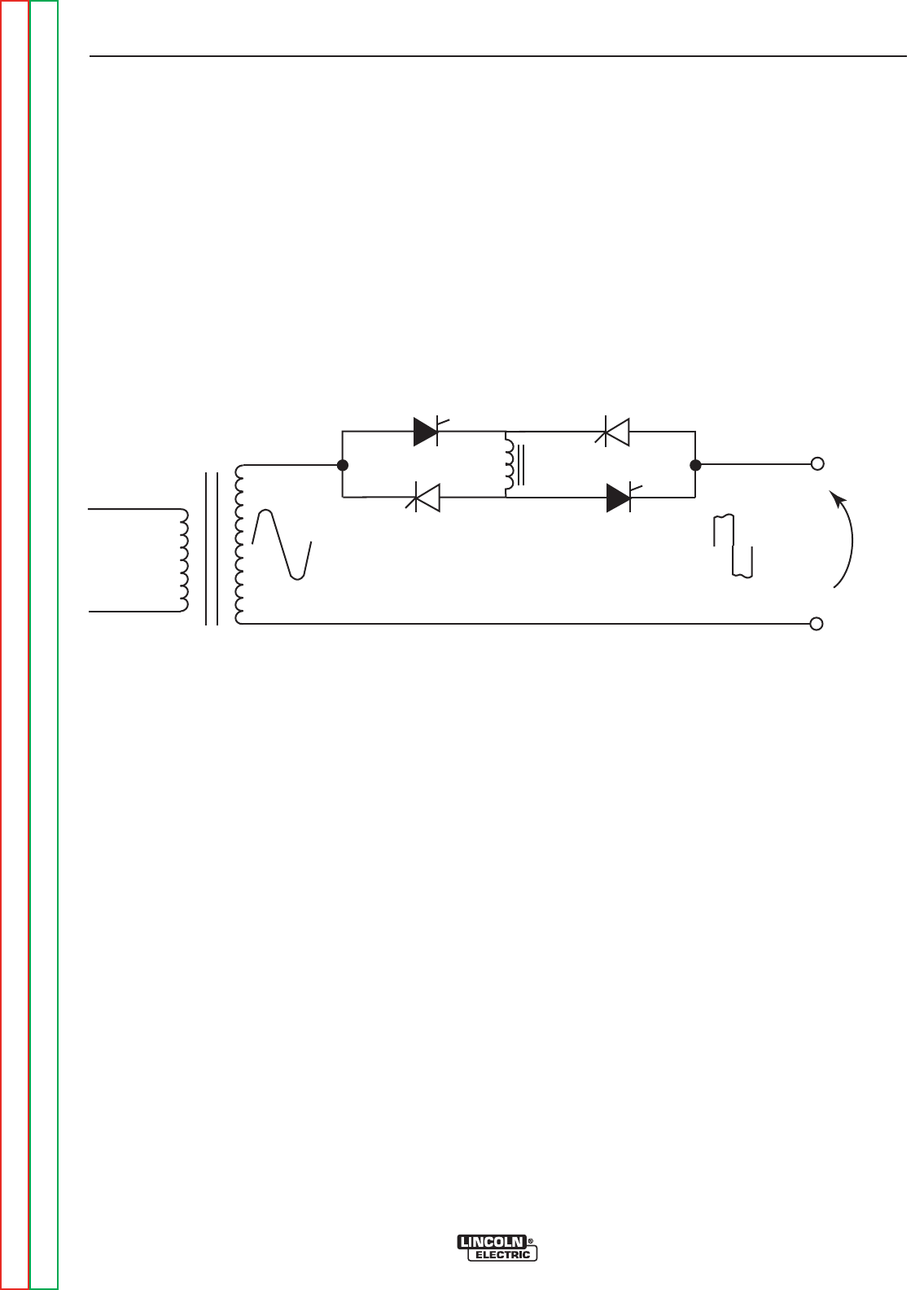
THEORY OF OPERATION
E-6 E-6
PRECISION TIG® 225
Return to Section TOC Return to Section TOC Return to Section TOC Return to Section TOC
Return to Master TOC Return to Master TOC Return to Master TOC Return to Master TOC
AC WELDING OUTPUT
Rotating the polarity switch to the AC position changes the welding power circuit. One lead (X1) of the main
transformer secondary is connected to the machine output work terminal. The other secondary lead (X2) is con-
nected to one of the AC connections on the SCR bridge. The electrode terminal is connected to the other AC
side of the bridge. The choke is now electrically across the negative and positive SCR bridge connections. With
the ability of the choke to store energy and the SCRs to turn on at the appropriate times, an AC square wave is
developed and applied to the output terminals.
FIGURE E.6 AC Square Wave Welding Current Generation.
CHOKE
WORK
ELECTRODE
PRIMARY
1Ø
G
G
G
G
DC
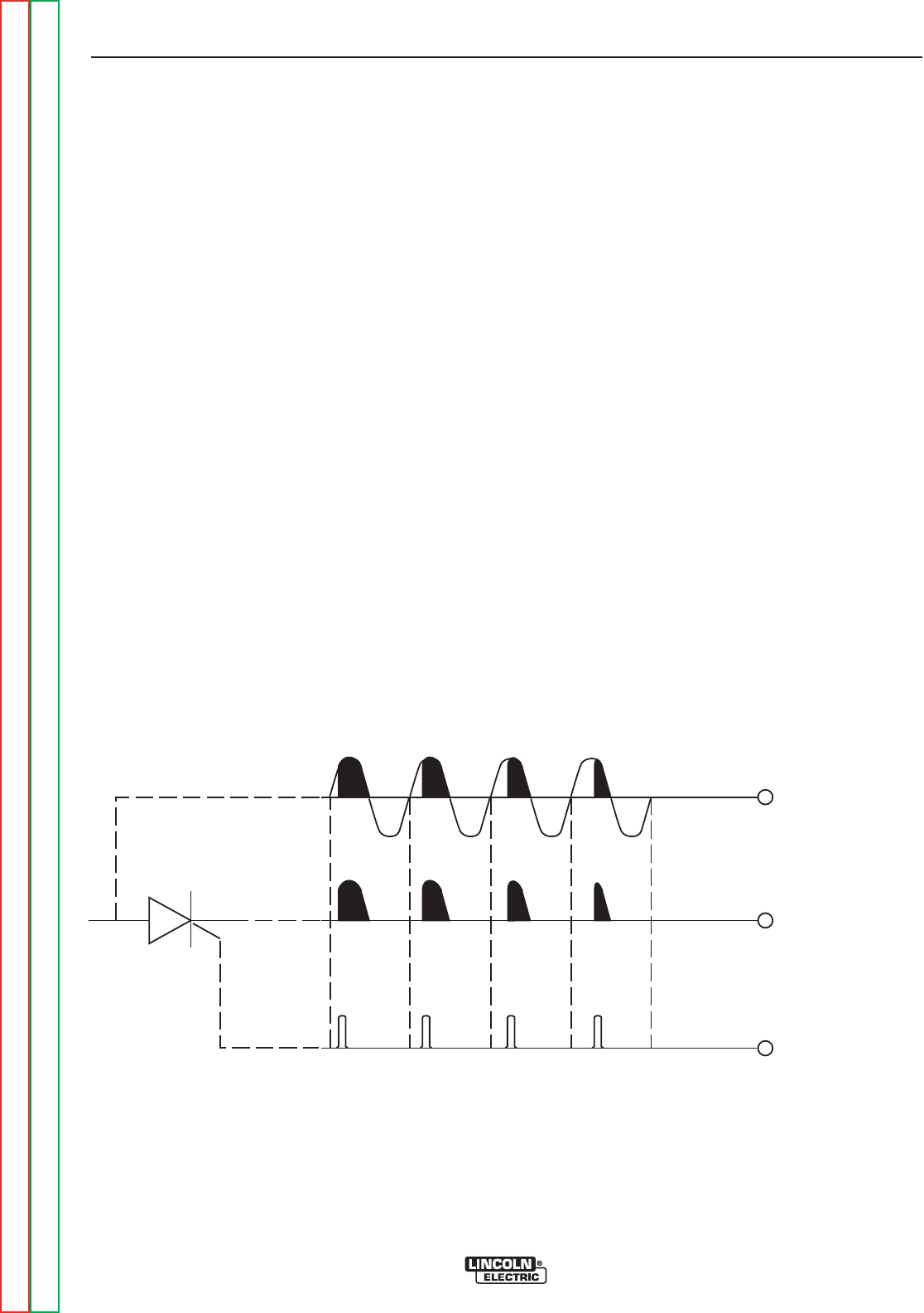
THEORY OF OPERATION
E-7 E-7
PRECISION TIG® 225
Return to Section TOC Return to Section TOC Return to Section TOC Return to Section TOC
Return to Master TOC Return to Master TOC Return to Master TOC Return to Master TOC
SCR OPERATION
A silicon controlled rectifier (SCR) is a three terminal
device used to control rather large currents to a load.
An SCR acts very much like a switch. When a gate
signal is applied to the SCR it is turned ON and there
is current flow from anode to cathode. In the ON state
the SCR acts like a closed switch. When the SCR is
turned OFF there is no current flow from anode to
cathode thus the device acts like an open switch. As
the name suggests, the SCR is a rectifier, so it pass-
es current only during positive half cycles of the AC
supply. The positive half cycle is the portion of the
sine wave in which the anode of the SCR is more
positive than the cathode.
When an AC supply voltage is applied to the SCR, the
device spends a certain portion of the AC cycle time in
the on state and the remainder of the time in the off
state. The amount of time spent in the ON state is con-
trolled by the Gate.
An SCR is fired by a short burst of current into the gate.
This gate pulse must be more positive than the cath-
ode voltage. Since there is a standard PN junction
between gate and cathode, the voltage between these
terminals must be slightly greater than 0.6V. Once the
SCR has fired it is not necessary to continue the flow
of gate current. As long as current continues to flow
from anode to cathode the SCR will remain on. When
the anode to cathode current drops below a minimum
value, called holding current, the SCR will shut off.
This normally occurs as the AC supply voltage passes
through zero into the negative portion of the sine wave.
If the SCR is turned on early in the positive half cycle,
the conduction time is longer resulting in greater SCR
output. If the gate firing occurs later in the cycle the
conduction time is less resulting in lower SCR output.
FIGURE E.7 SCR Operation
CATHODE
ANODE
GATE
GATE
INPUT
OUTPUT NOTE: AS THE GATE
PULSE IS APPLIED
LATER IN THE CYCLE
THE SCR OUTPUT
IS DECREASED.

THEORY OF OPERATION
E-8 E-8
PRECISION TIG® 225
Return to Section TOC Return to Section TOC Return to Section TOC Return to Section TOC
Return to Master TOC Return to Master TOC Return to Master TOC Return to Master TOC
PROTECTIVE CIRCUITS
Protective circuits are designed into the PRECISION
TIG® 185 to sense trouble and shut down the machine
before the trouble damages the internal machine com-
ponents. Both thermal protection and current overload
are included. Fan as needed (F.A.N.) Fan runs for 5
seconds at power-up and stops at idle 8 minutes after
welding.
THERMAL PROTECTION
OVER TEMPERATURE LIGHT- If the welder
overheats due to blocked air flow, high ambient air
temperature, or exceeded duty cycle, an internal ther-
mostat will open disabling the welding output and this
yellow light will illuminate. The cooling fans will contin-
ue to run to cool the unit during this time. The light will
go out when the unit cools and the thermostat resets.
Once the light goes out, the machine will again
become available to weld.
Once the machine cools sufficiently the thermostats
are self-resetting. If the thermostat shutdown is caused
by excessive output or duty cycle and the fan is oper-
ating normally, the power may be left on, and the reset
should occur within a 15 minute period. If the fan is not
functioning properly or the air intake louvers are
obstructed, then the input power must be removed and
the fan problem or air obstruction corrected.
OVERLOAD PROTECTION
The machine is electronically protected from producing
excessively high output currents. The output is limited
to 200 amps.
115 VAC RECEPTACLE
The auxiliary receptacle is circuit breaker protected.
Canadian {K2J33-2} and International {K2J34-1}
modes are 6 amps. K2533-1 and K2535-1/-2
208/230/1/60 modes are rated 20 amps.

TABLE OF CONTENTS - TROUBLESHOOTING AND REPAIR
F-1 F-1
Return to Master TOC Return to Master TOC Return to Master TOC Return to Master TOC
PRECISION TIG® 225
Troubleshooting and Repair.............................................................................................................................F-1
How to Use Troubleshooting Guide .......................................................................................................F-2
PC Board Troubleshooting Procedures and Replacement ....................................................................F-3
Troubleshooting Guide ...........................................................................................................................F-4
Test Procedures
High Frequency Circuit Disable Procedure ..........................................................................................F-15
T1 Transformer Test .............................................................................................................................F-17
Static SCR Test ....................................................................................................................................F-21
Active SCR Test ...................................................................................................................................F-25
Oscilloscope Waveforms
Normal Open Circuit Voltage Waveform-AC TIG Mode.......................................................................F-29
Normal Open Circuit Voltage Waveform-DC TIG Mode.......................................................................F-30
Normal Open Circuit Voltage Waveform-AC Stick Mode .....................................................................F-31
Normal Open Circuit Voltage Waveform-DC Stick Mode.....................................................................F-32
Typical Output Voltage Waveform-Machine Loaded AC TIG Mode .....................................................F-33
Typical Output Voltage Waveform-Machine Loaded DC TIG Mode.....................................................F-34
Typical Output Voltage Waveform-Machine Loaded AC Stick Mode ...................................................F-35
Typical Output Voltage Waveform-Machine Loaded DC Stick Mode...................................................F-36
Abnormal Open Circuit Voltage-DC TIG Mode One SCR not Functioning..........................................F-37
Replacement Procedures
SCR Bridge Assembly Removal and Replacement .............................................................................F-39
Polarity Switch Removal and Replacement .........................................................................................F-45
High Voltage Transformer Removal and Replacement........................................................................F-49
Main Transformer and Output Choke Removal and Replacement ......................................................F-53
Retest after Repair......................................................................................................................................F-55

TROUBLESHOOTING AND REPAIR
F-2 F-2
PRECISION TIG® 225
Return to Section TOC Return to Section TOC Return to Section TOC Return to Section TOC
Return to Master TOC Return to Master TOC Return to Master TOC Return to Master TOC
This Troubleshooting Guide is provided to
help you locate and repair possible machine
malfunctions. Simply follow the three-step
procedure listed below.
Step 1. LOCATE PROBLEM (SYMPTOM).
Look under the column labeled “PROBLEM
(SYMPTOMS)”. This column describes pos-
sible symptoms that the machine may exhib-
it. Find the listing that best describes the
symptom that the machine is exhibiting.
Symptoms are grouped into the following
categories: output problems, function prob-
lems, wire feeding problems, and welding
problems.
Step 2. PERFORM EXTERNAL TESTS.
The second column labeled “POSSIBLE
AREAS OF MISADJUSTMENT(S)” lists the
obvious external possibilities that may con-
tribute to the machine symptom. Perform
these tests/checks in the order listed. In
general, these tests can be conducted with-
out removing the case wrap-around cover.
Step 3. RECOMMENDED
COURSE OF ACTION
The last column labeled “Recommended
Course of Action” lists the most likely com-
ponents that may have failed in your
machine. It also specifies the appropriate
test procedure to verify that the subject com-
ponent is either good or bad. If there are a
number of possible components, check the
components in the order listed to eliminate
one possibility at a time until you locate the
cause of your problem.
All of the referenced test procedures
referred to in the Troubleshooting Guide are
described in detail at the end of this chapter.
Refer to the Troubleshooting and Repair
Table of Contents to locate each specific
Test Procedure. All of the specified test
points, components, terminal strips, etc. can
be found on the referenced electrical wiring
diagrams and schematics. Refer to the
Electrical Diagrams Section Table of
Contents to locate the appropriate diagram.
HOW TO USE TROUBLESHOOTING GUIDE
Service and Repair should only be performed by Lincoln Electric Factory Trained
Personnel. Unauthorized repairs performed on this equipment may result in danger to
the technician and machine operator and will invalidate your factory warranty. For your
safety and to avoid Electrical Shock, please observe all safety notes and precautions
detailed throughout this manual.
---------------------------------------------------------------------------------------------------------------------------
WARNING
CAUTION
If for any reason you do not understand the test procedures or are unable to perform the
tests/repairs safely, contact the Lincoln Electric Service Department for technical troubleshooting
assistance before you proceed. Call 1-888-935-3877.
-----------------------------------------------------------------------------------------------------------------------------------
TROUBLESHOOTING AND REPAIR
F-3 F-3
PRECISION TIG® 225
Return to Section TOC Return to Section TOC Return to Section TOC Return to Section TOC
Return to Master TOC Return to Master TOC Return to Master TOC Return to Master TOC
Sometimes machine failures appear to be due to PC
board failures. These problems can sometimes be
traced to poor electrical connections. To avoid prob-
lems when troubleshooting and replacing PC boards,
please use the following procedure:
1. Determine to the best of your technical ability
that the PC board is the most likely component
causing the failure symptom.
2. Check for loose connections at the PC board
to assure that the PC board is properly
connected.
3. If the problem persists, replace the suspect PC
board using standard practices to avoid static
electrical damage and electrical shock. Read
the warning inside the static resistant bag and
perform the following procedures:
PC board can be damaged by static electricity.
- Remove your body’s static
charge before opening the static-
shielding bag. Wear an anti-static
wrist strap. For safety, use a 1
Meg ohm resistive cord connected
to a grounded part of the
equipment frame.
- If you don’t have a wrist strap,
touch an un-painted, grounded,
part of the equipment frame. Keep
touching the frame to prevent
static build-up. Be sure not to
touch any electrically live parts at
the same time.
- Tools which come in contact with the PC board must
be either conductive, anti-static or static-dissipative.
ELECTRIC SHOCK
can kill.
•Have an electrician install and
service this equipment. Turn the
input power OFF at the fuse box
before working on equipment. Do
not touch electrically hot parts.
- Remove the PC board from the static-shielding bag
and place it directly into the equipment. Don’t set the
PC board on or near paper, plastic or cloth which
could have a static charge. If the PC board can’t be
installed immediately, put it back in the static-shield-
ing bag.
- If the PC board uses protective shorting jumpers,
don’t remove them until installation is complete.
- If you return a PC board to The Lincoln Electric
Company for credit, it must be in the static-shielding
bag. This will prevent further damage and allow prop-
er failure analysis.
4. Test the machine to determine if the failure
symptom has been corrected by the
replacement PC board.
NOTE:It is desirable to have a spare (known good)
PC board available for PC board troubleshooting.
NOTE:Allow the machine to heat up so that all
electrical components can reach their operating
temperature.
5. Remove the replacement PC board and
substitute it with the original PC board to
recreate the original problem.
a. If the original problem does not reappear by
substituting the original board, then the PC
board was not the problem. Continue to look
for bad connections in the control wiring
harness, junction blocks, and terminal strips.
b. If the original problem is recreated by the
substitution of the original board, then the PC
board was the problem. Reinstall the
replacement PC board and test the machine.
6. Always indicate that this procedure was
followed when warranty reports are to be
submitted.
NOTE:Following this procedure and writing on the
warranty report, “INSTALLED AND SWITCHED PC
BOARDS TO VERIFY PROBLEM,” will help avoid
denial of legitimate PC board warranty claims.
PC BOARD TROUBLESHOOTING PROCEDURES
ATTENTION
Static-Sensitive
Devices
Handle only at
Static-Safe
Workstations
WARNING
CAUTION

OUTPUT PROBLEMS
Observe Safety Guidelines detailed in the beginning of this manual.
PROBLEMS
(SYMPTOMS)
POSSIBLE AREAS OF
MISADJUSTMENT(S)
RECOMMENDED
COURSE OF ACTION
If for any reason you do not understand the test procedures or are unable to perform the tests/repairs safely,
contact the Lincoln Electric Service Department for technical troubleshooting assistance before you proceed.
Call 1-888-935-3877.
CAUTION
Machine is dead. No output - No
fan-No115VACatreceptacle.
1. Make sure that the input power
switch is in the "ON" position
and the machine is plugged in.
2. Check the input voltage at the
machine. Input voltage must
match the rating plate and volt-
age connection. Refer to
Reconnect Procedure in the
Installation section of this manu-
al.
3. Blown or missing fuses in the
input line.
4. CB-1 circuit breaker open.
1. Check the input power switch
and associated wires for loose
or faulty connections.
2. Perform the T1 Transformer
Test.
The fan runs normally. No output
from the machine in either Stick or
TIG modes.
1. Check for proper input voltages
per nameplate and voltage
reconnect configuration.
2. Check to make sure the polarity
switch is in the proper position
and functioning correctly.
1. Check for loose or faulty con-
nections on the heavy current
carrying leads. (polarity switch,
output choke output terminals
etc.)
2. Perform the T1 Transformer
Test.
3. Perform the SCR Bridge Test.
4. Check current control R1 for
proper operation. Normal
resistance is 10,000 ohms.
Also check associated leads
for loose or faulty connections.
5. The control board may be
faulty. Replace.
TROUBLESHOOTING AND REPAIR
F-4 F-4
PRECISION TIG® 225
Return to Section TOC Return to Section TOC Return to Section TOC Return to Section TOC
Return to Master TOC Return to Master TOC Return to Master TOC Return to Master TOC

OUTPUT PROBLEMS
Observe Safety Guidelines detailed in the beginning of this manual.
PROBLEMS
(SYMPTOMS)
POSSIBLE AREAS OF
MISADJUSTMENT(S)
RECOMMENDED
COURSE OF ACTION
If for any reason you do not understand the test procedures or are unable to perform the tests/repairs safely,
contact the Lincoln Electric Service Department for technical troubleshooting assistance before you proceed.
Call 1-888-935-3877.
CAUTION
Fan runs - No output from
machine in either Stick or TIG
modes and the yellow light on the
control panel is on.
1. The welding application may
have exceeded the recommend-
ed duty cycle. Allow the unit to
run until the fan cools the unit
and the yellow light goes out.
2. The air louvers may be blocked.
Remove air obstruction and
allow unit to cool.
1. One of the thermostats may be
faulty. Check or replace. See
wiring diagram.
2. Check for loose or faulty wires
on the thermostats and associ-
ated circuitry. See wiring dia-
gram.
The machine does not respond (no
gas flow, no high frequency and no
open circuit voltage) when the arc
start switch or Amptrol is activated
- fan is working normally.
1. Make certain the machine is in
the TIG mode.
2. The Amptrol may be defective.
Check for continuity(zero ohms)
between pins "D" and "E" on
cable connector when the
Amptrol is depressed.
1. Check the continuity (zero
ohms) of the leads between the
remote receptacle and plug J5
on the control board. See
wiring diagram.
2. Perform the T1 Transformer
Test.
3. The control board may be
faulty. Replace.
TROUBLESHOOTING AND REPAIR
F-5 F-5
PRECISION TIG® 225
Return to Section TOC Return to Section TOC Return to Section TOC Return to Section TOC
Return to Master TOC Return to Master TOC Return to Master TOC Return to Master TOC

OUTPUT PROBLEMS
Observe Safety Guidelines detailed in the beginning of this manual.
PROBLEMS
(SYMPTOMS)
POSSIBLE AREAS OF
MISADJUSTMENT(S)
RECOMMENDED
COURSE OF ACTION
If for any reason you do not understand the test procedures or are unable to perform the tests/repairs safely,
contact the Lincoln Electric Service Department for technical troubleshooting assistance before you proceed.
Call 1-888-935-3877.
CAUTION
Machine regularly over heats -
thermostat opens. Yellow light on
front panel glows. The fan runs
but the machine has no output.
Machine regularly over heats - ther-
mostat opens. Yellow light on front
panel glows. The fan runs but the
machine has no output.
1. The thermostat(s) may be
faulty. Check or replace.
2. The control board may be
faulty.
The machine does not have output
in the Stick mode. The machine
operates correctly in the TIG mode.
The machine does not have output
in the Stick mode. The machine
operates correctly in the TIG mode.
1. Check the Stick/TIG switch(S3)
and associated leads. See
wiring diagram.
2. The control board may be
faulty.
TROUBLESHOOTING AND REPAIR
F-6 F-6
PRECISION TIG® 225
Return to Section TOC Return to Section TOC Return to Section TOC Return to Section TOC
Return to Master TOC Return to Master TOC Return to Master TOC Return to Master TOC

OUTPUT PROBLEMS
Observe Safety Guidelines detailed in the beginning of this manual.
PROBLEMS
(SYMPTOMS)
POSSIBLE AREAS OF
MISADJUSTMENT(S)
RECOMMENDED
COURSE OF ACTION
If for any reason you do not understand the test procedures or are unable to perform the tests/repairs safely,
contact the Lincoln Electric Service Department for technical troubleshooting assistance before you proceed.
Call 1-888-935-3877.
CAUTION
Machine welds at a very low out-
put regardless of the current con-
trol setting.
1. If welding in the TIG mode the
remote control device may be
defective.
2. Make certain the input line volt-
age is correct for the machine
reconnect configuration.
3. Check the welding cables and or
torch for loose or faulty connec-
tions.
1. Check the polarity switch and
associated leads.
2. Check the interior connections
of the heavy current carrying
leads.
3. Perform the SCR Bridge Test.
4. Perform the T1 Transformer
Test.
5. Check the current control for
proper operation. Normal
resistance is 10k ohms. See
wiring diagram.
6. The control board may be
faulty.
The machine welds at a very high
output regardless of the current
control setting.
1. If welding in the TIG mode the
remote control device may be
defective.
1. Perform the SCR Bridge Test.
2. Perform the T1 Transformer
Test.
3. Check the current control for
proper operation. Normal
resistance is 10k ohms. See
wiring diagram.
4. The control board may be
faulty.
TROUBLESHOOTING AND REPAIR
F-7 F-7
PRECISION TIG® 225
Return to Section TOC Return to Section TOC Return to Section TOC Return to Section TOC
Return to Master TOC Return to Master TOC Return to Master TOC Return to Master TOC

OUTPUT PROBLEMS
Observe Safety Guidelines detailed in the beginning of this manual.
PROBLEMS
(SYMPTOMS)
POSSIBLE AREAS OF
MISADJUSTMENT(S)
RECOMMENDED
COURSE OF ACTION
If for any reason you do not understand the test procedures or are unable to perform the tests/repairs safely,
contact the Lincoln Electric Service Department for technical troubleshooting assistance before you proceed.
Call 1-888-935-3877.
CAUTION
Machine output is intermittently
lost. Gas flow and high frequency
are also interrupted.
1. The problem may be caused by
high frequency interference.
Make sure that the machine is
grounded properly according to
the installation instructions. If
there are other high frequency
sources in the area, make cer-
tain that they are grounded
properly.
2. Make sure the Amptrol is operat-
ing properly.
3. Check to make sure that the
input voltage is correct for the
machine reconnect configura-
tion. Refer to Reconnect
Procedure in the Installation
section of this manual.
1. Check for loose or faulty con-
nection on the leads between
the remote receptacle and plug
J5 on the control board. See
wiring diagram.
2. Check the plugs on the control
board for loose connections.
3. The control board may be
faulty.
TROUBLESHOOTING AND REPAIR
F-8 F-8
PRECISION TIG® 225
Return to Section TOC Return to Section TOC Return to Section TOC Return to Section TOC
Return to Master TOC Return to Master TOC Return to Master TOC Return to Master TOC

OUTPUT PROBLEMS
Observe Safety Guidelines detailed in the beginning of this manual.
PROBLEMS
(SYMPTOMS)
POSSIBLE AREAS OF
MISADJUSTMENT(S)
RECOMMENDED
COURSE OF ACTION
If for any reason you do not understand the test procedures or are unable to perform the tests/repairs safely,
contact the Lincoln Electric Service Department for technical troubleshooting assistance before you proceed.
Call 1-888-935-3877.
CAUTION
The arc "flutters" when TIG weld-
ing.
1. The tungsten electrode may be
too large in diameter for the cur-
rent setting.
2. The tungsten tip may not be
"sharp" enough.
3. The gas shielding may be insuf-
ficient. Increase the gas flow
and or reduce the tungsten
stickout beyond the gas cup.
4. Check for contaminated gas or
leaks in the gas line, torch, or
connections.
5. If a helium blend is used as a
shielding gas then reduce the
percentage of helium.
1. Check the polarity switch for
proper operation and loose or
faulty lead connections. See
wiring diagram.
2. Perform the SCR Bridge Test.
3. Check for loose or faulty con-
nections at the shunt. ( leads
#221 and #222 ).
4. Check components R3 and C4
in the high voltage transformer
primary circuit. Replace if nec-
essary. See wiring diagram.
5. The control board may be
faulty. Replace.
The arc "pulsates" when AC TIG
welding.
1. Make sure the gas and proce-
dure are correct for the process
being used.
1. Check the micro switch S2A on
the polarity switch. It may be
stuck closed. See wiring dia-
gram.
TROUBLESHOOTING AND REPAIR
F-9 F-9
PRECISION TIG® 225
Return to Section TOC Return to Section TOC Return to Section TOC Return to Section TOC
Return to Master TOC Return to Master TOC Return to Master TOC Return to Master TOC

OUTPUT PROBLEMS
Observe Safety Guidelines detailed in the beginning of this manual.
PROBLEMS
(SYMPTOMS)
POSSIBLE AREAS OF
MISADJUSTMENT(S)
RECOMMENDED
COURSE OF ACTION
If for any reason you do not understand the test procedures or are unable to perform the tests/repairs safely,
contact the Lincoln Electric Service Department for technical troubleshooting assistance before you proceed.
Call 1-888-935-3877.
CAUTION
Black areas along weld bead. 1. Clean any oily or organic conta-
mination from the work piece.
2. Tungsten electrode may be con-
taminated. Replace or sharpen.
3. Check for contaminated gas or
leaks in the gas line, torch, or
associated connections.
4. The gas shielding may be insuf-
ficient. Increase gas flow:
reduce tungsten stickout beyond
the gas cup.
1. This may be a welding proce-
dure problem.
Contact The Lincoln Electric
Service Department, 1-888-935-
3877.
Weak high frequency - machine
has normal welding.
1. Check for loose or faulty con-
nections at the torch and/or
welding cables.
2. The gas shielding may be insuf-
ficient. Increase gas flow:
reduce tungsten stickout beyond
the gas cup.
3. Check spark gap operation and
setting. Normal is (0.015").
Refer to Maintenance section of
this manual.
4. The work and electrode cables
may be in poor condition allow-
ing the high frequency to "leak
off". Use good quality cables
with a high natural rubber con-
tent, such as Lincoln Stable Arc
Cable. Cables should be as
short as possible.
1. Make sure that 115VAC is
being applied to the primary of
the high voltage transformer
(T3). See wiring diagram.
2. Check for any open or arcing
high frequency component.
Replace as required.
(Examples: C3, R3, C4)
3. If spark is weak at the spark
gap, check or replace the high
frequency circuit.
(Examples: T3, L3, L4).
TROUBLESHOOTING AND REPAIR
F-10 F-10
PRECISION TIG® 225
Return to Section TOC Return to Section TOC Return to Section TOC Return to Section TOC
Return to Master TOC Return to Master TOC Return to Master TOC Return to Master TOC

OUTPUT PROBLEMS
Observe Safety Guidelines detailed in the beginning of this manual.
PROBLEMS
(SYMPTOMS)
POSSIBLE AREAS OF
MISADJUSTMENT(S)
RECOMMENDED
COURSE OF ACTION
If for any reason you do not understand the test procedures or are unable to perform the tests/repairs safely,
contact the Lincoln Electric Service Department for technical troubleshooting assistance before you proceed.
Call 1-888-935-3877.
CAUTION
High frequency "spark" is present
at tungsten electrode, but operator
is unable to establish a welding
arc. Machine has normal open cir-
cuit voltage. Refer to Technical
Specifications in the Installation
Chapter.
1. The torch may be faulty. Check
or replace.
2. The current control may be set
too low.
3. The tungsten electrode may be
contaminated. Replace or
sharpen.
4. The electrode may be too large
for the process.
5. If a helium blend is being used
as a shielding gas, then reduce
the percentage of helium.
6. Check the welding cables for
loose or faulty connections.
1. This may be a welding proce-
dure problem.
Contact The Lincoln Electric
Service Department 1-888-935-
3877.
TROUBLESHOOTING AND REPAIR
F-11 F-11
PRECISION TIG® 225
Return to Section TOC Return to Section TOC Return to Section TOC Return to Section TOC
Return to Master TOC Return to Master TOC Return to Master TOC Return to Master TOC
OUTPUT PROBLEMS
Observe Safety Guidelines detailed in the beginning of this manual.
PROBLEMS
(SYMPTOMS)
POSSIBLE AREAS OF
MISADJUSTMENT(S)
RECOMMENDED
COURSE OF ACTION
If for any reason you do not understand the test procedures or are unable to perform the tests/repairs safely,
contact the Lincoln Electric Service Department for technical troubleshooting assistance before you proceed.
Call 1-888-935-3877.
CAUTION
No high frequency. Machine is in
the TIG mode and has normal out-
put.
1. If the machine location is in a
highly dirty environment with
conductive contaminant's, check
and clean the spark gap with a
low pressure air stream per the
maintenance instructions.
2. Check spark gap operation and
setting. Normal is (0.020").
Refer to Maintenance section
of this manual.
1. Check the high voltage trans-
former (T3). The normal resis-
tance of the secondary winding
of the high voltage transformer
is 12.5k ohms.
ELECTRIC SHOCK CAN
KILL. When 115VAC is
applied to the primary of T3. A
very high voltage is developed on
the secondary winding. For
assistance call the Lincoln Electric
Service Department 1-888-935-
3877.
----------------------------------------------
2. CheckthevaluesofR3,and
C4.
3. Perform the T1 Transformer
Test.
4. The control board may be
faulty. Replace.
No gas flow when Amptrol is acti-
vated in the TIG mode. Machine
has normal output - fan runs.
A "click" can be heard indicating
that the gas solenoid valve is oper-
ating.
1. The gas supply is either empty
or not turned on.
2. The flow regulator may be set
too low.
3. Check the gas hose for kinks or
blockages.
4. Check the filter screen inside
gas inlet fitting to solenoid valve.
1. Possible gas supply problems.
Consult your local welder/gas dis-
tributor.
TROUBLESHOOTING AND REPAIR
F-12 F-12
PRECISION TIG® 225
Return to Section TOC Return to Section TOC Return to Section TOC Return to Section TOC
Return to Master TOC Return to Master TOC Return to Master TOC Return to Master TOC
WARNING

OUTPUT PROBLEMS
Observe Safety Guidelines detailed in the beginning of this manual.
PROBLEMS
(SYMPTOMS)
POSSIBLE AREAS OF
MISADJUSTMENT(S)
RECOMMENDED
COURSE OF ACTION
If for any reason you do not understand the test procedures or are unable to perform the tests/repairs safely,
contact the Lincoln Electric Service Department for technical troubleshooting assistance before you proceed.
Call 1-888-935-3877.
CAUTION
When AC TIG welding, the arc is
erratic and there is a loss of
"cleaning" of the work piece.
1. The tungsten electrode may be
too small for the process. Use
a larger diameter tungsten or a
pure tungsten.
2. If a helium blend is used as a
shielding gas, then reduce the
percentage of helium.
1. Check components R3 and C4
in the high voltage transformer
primary circuit.
2. Perform the SCR Bridge Test.
The end of the tungsten electrode
melts away.
1. The welding current is too high
for the electrode type and or
size. See Table B.1 in the
Operation Section.
1. This may be a welding proce-
dure problem.
Contact The Lincoln Electric
Service Department 1-888-935-
3877.
TROUBLESHOOTING AND REPAIR
F-13 F-13
PRECISION TIG® 225
Return to Section TOC Return to Section TOC Return to Section TOC Return to Section TOC
Return to Master TOC Return to Master TOC Return to Master TOC Return to Master TOC

OUTPUT PROBLEMS
Observe Safety Guidelines detailed in the beginning of this manual.
PROBLEMS
(SYMPTOMS)
POSSIBLE AREAS OF
MISADJUSTMENT(S)
RECOMMENDED
COURSE OF ACTION
If for any reason you do not understand the test procedures or are unable to perform the tests/repairs safely,
contact the Lincoln Electric Service Department for technical troubleshooting assistance before you proceed.
Call 1-888-935-3877.
CAUTION
Stick electrode "Blasts Off" when
arc is struck.
1. Weld current may be set too
high for electrode size. Reduce
current control setting, or use a
larger diameter electrode.
1. Perform the SCR Bridge Test.
2. The control board may be
faulty. Replace.
The stick electrode "sticks" in the
puddle.
1. The weld current may be set too
low. Increase the current control
setting or use a smaller diameter
electrode.
Variable or sluggish welding arc
when welding in the Stick mode.
1. Check work and electrode
cablesforlooseorpoorconnec-
tions.
2. The weld cables may be too
small or too long to permit the
desired current to flow.
3. The weld current may be set too
low.
1. Check the polarity switch for
excessive wear or faulty connec-
tions.
2. Check interior connection of the
heavy current carrying leads.
TROUBLESHOOTING AND REPAIR
F-14 F-14
PRECISION TIG® 225
Return to Section TOC Return to Section TOC Return to Section TOC Return to Section TOC
Return to Master TOC Return to Master TOC Return to Master TOC Return to Master TOC

HIGH FREQUENCY CIRCUIT DISABLE PROCEDURE
TROUBLESHOOTING AND REPAIR
F-15 F-15
PRECISION TIG® 225
Return to Section TOC Return to Section TOC Return to Section TOC Return to Section TOC
Return to Master TOC Return to Master TOC Return to Master TOC Return to Master TOC
WARNING
Service and repair should be performed by only Lincoln Electric factory trained personnel.
Unauthorized repairs performed on this equipment may result in danger to the technician
or machine operator and will invalidate your factory warranty. For your safety and to avoid
electrical shock, please observe all safety notes and precautions detailed throughout this
manual.
If for any reason you do not understand the test procedures or are unable to perform the
test/repairs safely, contact the Lincoln Electric Service Department for electrical trou-
bleshooting assistance before you proceed. Call 1-888-935-3877.
TEST DESCRIPTION
This procedure will disable the high frequency circuit. The technician will then be able to
take voltage measurements without the possibility of high frequency damage to his test
equipment.
MATERIALS NEEDED
3/8” Nutdriver
5/64” Allen type wrench
.020” feeler gauge
HIGH VOLTAGE IS STILL PRESENT IN THE HIGH FREQUENCY CIRCUIT.
----------------------------------------------------------------------------------------------------------------------
WARNING
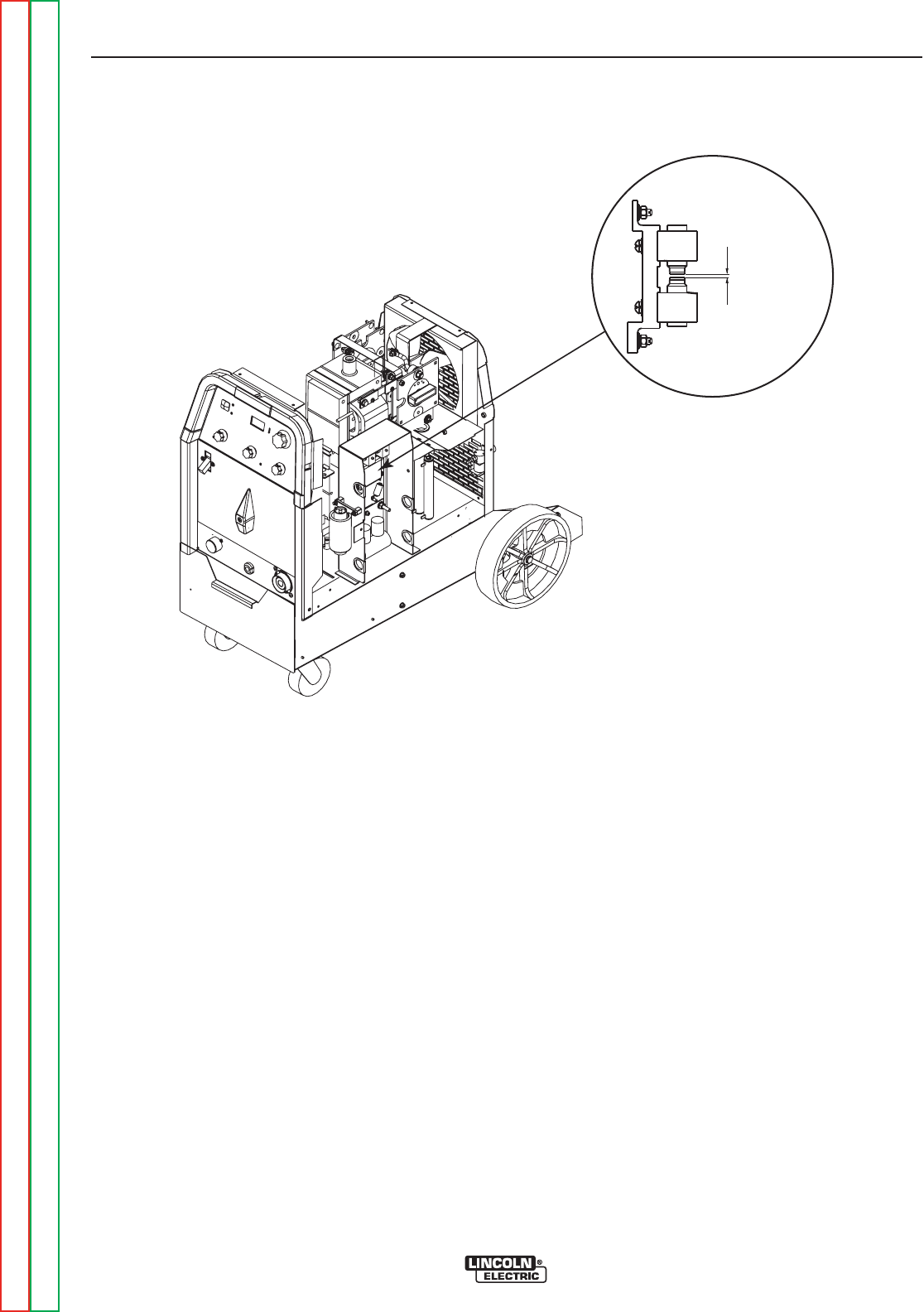
.020 Spark Gap
LEFT SIDE OF MACHINE
FIGURE F.1 – SPARK GAP ASSEMBLY
HIGH FREQUENCY CIRCUIT DISABLE PROCEDURE (continued)
TROUBLESHOOTING AND REPAIR
F-16 F-16
PRECISION TIG® 225
Return to Section TOC Return to Section TOC Return to Section TOC Return to Section TOC
Return to Master TOC Return to Master TOC Return to Master TOC Return to Master TOC
PROCEDURE
1. Remove input power to the TIG 225 machine.
2. Using the 3/8” nutdriver remove the right side
panel.
3. Locate the Spark Gap Assembly at the right
side of the machine. See Figure F.1.
4. With the 5/64” Allen type wrench loosen the set
screw holding the upper electrode in place.
5. Increase the distance between the electrodes
to at least 3/8” by sliding one electrode away
from the other electrode. Secure the one elec-
trode in this position.
6. This should disable the high frequency circuit.
Visually check to make sure high frequency
sparking is NOT present before connecting
any test equipment to the TIG 225 machine.
7. When voltage testing and scope measurements
are complete reset the spark gap electrodes to
.020” air gap. Tighten the set screw using the
5/64” Allen wrench.

Service and repair should be performed by only Lincoln Electric factory trained personnel.
Unauthorized repairs performed on this equipment may result in danger to the technician
or machine operator and will invalidate your factory warranty. For your safety and to avoid
electrical shock, please observe all safety notes and precautions detailed throughout this
manual.
If for any reason you do not understand the test procedures or are unable to perform the
test/repairs safely, contact the Lincoln Electric Service Department for electrical trou-
bleshooting assistance before you proceed. Call 1-888-935-3877.
TEST DESCRIPTION
This procedure will determine if the correct voltage is being applied to the primary of the
T1 transformer and also if the correct voltages are being induced on the secondary wind-
ings of the transformer.
MATERIALS NEEDED
Volt/Ohm Meter
PRECISION TIG® 225 Wiring Diagrams
3/8” nutdriver
T1 TRANSFORMER TEST
TROUBLESHOOTING AND REPAIR
F-17 F-17
PRECISION TIG® 225
Return to Section TOC Return to Section TOC Return to Section TOC Return to Section TOC
Return to Master TOC Return to Master TOC Return to Master TOC Return to Master TOC
WARNING
PRECISION TIG 225 CONTROL BOARD
J2
J3
J4
PIN 4 (LEAD #201)
PIN 3 (LEAD #204)
PIN 7 (LEAD #210)
PIN 8 (LEAD #209)
PIN 3 (LEAD #232)
PIN 2 (LEAD #260)
T1 TRANSFORMER TEST (continued)
PROCEDURE
1. Remove main supply power to the machine.
2. Using the 3/8” nutdriver remove the case wrap-
around cover.
3. Locate plugs J3 and J4 on the
control board. See Figure F.2.
4. Carefully apply the correct input power making
certain the reconnect configuration at the input
switch is correct for the input voltage applied.
Turn the TIG 225 ON.
5. Using the voltmeter carefully test for the correct
transformer secondary voltages per Table F.1.
TROUBLESHOOTING AND REPAIR
F-18 F-18
PRECISION TIG® 225
Return to Section TOC Return to Section TOC Return to Section TOC Return to Section TOC
Return to Master TOC Return to Master TOC Return to Master TOC Return to Master TOC
FIGURE F.2 – Plugs J3 & J4 on Control Board

T1 TRANSFORMER TEST (continued)
PROCEDURE
6. If all of the secondary voltages are correct the
T1 transformer is functioning properly.
A. If all of the secondary voltages are missing
or incorrect make certain that the correct
input voltage is being applied to the correct
primary leads. See Table F.1.
B. If the correct input voltage is being applied to
the primary leads and any or all of the sec-
ondary voltages are incorrect the T1 trans-
former may be faulty. See Main
Transformer and Output Choke Removal
and Replacement. Also check the leads for
broken or loose connections between plugs
J3, J4 and the T1 transformer.
7. Replace case wrap-around cover.
TROUBLESHOOTING AND REPAIR
F-19 F-19
PRECISION TIG® 225
Return to Section TOC Return to Section TOC Return to Section TOC Return to Section TOC
Return to Master TOC Return to Master TOC Return to Master TOC Return to Master TOC
TEST POINTS ACCEPTABLE VOLTAGES
SECONDARY WINDINGS SECONDARY VOLTAGES
PLUG J3 PIN 8 (LEAD #210)
TO 18VAC
PLUG J3 PIN 7 (LEAD #209)
PLUG J3 PIN 4 (LEAD #201)
TO 18VAC
PLUG J3 PIN 3 (LEAD #204)
PLUG J4 PIN 2 (LEAD #260) CHECK DURING FIRST 5 SECONDS OF POWER UP
TO 115VAC
PLUG J4 PIN 3 (LEAD #232)
X1 TO X2 80 VAC
PRIMARY WINDINGS PRIMARY VOLTAGES
H1 TO H2 208VAC
H1 TO H3 230VAC
TABLE F.1 T1 TRANSFORMER VOLTAGE
NOTE: If the input voltages vary the secondary voltages will vary accordingly.


Service and repair should be performed by only Lincoln Electric factory trained personnel.
Unauthorized repairs performed on this equipment may result in danger to the technician
or machine operator and will invalidate your factory warranty. For your safety and to avoid
electrical shock, please observe all safety notes and precautions detailed throughout this
manual.
If for any reason you do not understand the test procedures or are unable to perform the
test/repairs safely, contact the Lincoln Electric Service Department for electrical trou-
bleshooting assistance before you proceed. Call 1-888-935-3877.
TEST DESCRIPTION
This procedure is a quick check to determine if an SCR is shorted or “leaky”. See
machine waveform section for normal and abnormal SCR waveforms.
MATERIALS NEEDED
Volt/Ohm Meter (Analog)
PRECISION TIG® 225 Wiring Diagrams
3/8” nutdriver
SCR Heat Sink Assembly Drawing
STATIC SCR TEST
TROUBLESHOOTING AND REPAIR
F-21 F-21
PRECISION TIG® 225
Return to Section TOC Return to Section TOC Return to Section TOC Return to Section TOC
Return to Master TOC Return to Master TOC Return to Master TOC Return to Master TOC
WARNING
PLUG J2 REMOVED
PRECISION TIG 225 CONTROL
J2
J3
J4
STATIC SCR TEST (continued)
TEST PROCEDURE
1. Remove main supply power to the TIG 225 and
remove the case wrap-around cover.
2. Locate and remove plug J2 from the control
board. See Figure F.3.
TROUBLESHOOTING AND REPAIR
F-22 F-22
PRECISION TIG® 225
Return to Section TOC Return to Section TOC Return to Section TOC Return to Section TOC
Return to Master TOC Return to Master TOC Return to Master TOC Return to Master TOC
FIGURE F.3 – Plug J2 Location on Control Board
CASE COVER REMOVAL AND REPLACEMENT PROCEDURE (continued)
TEST PROCEDURE (continued)
3. Using an analog ohmmeter test the resistance
from anode to cathode of SCR1. Reverse the
meter leads and check from cathode to anode
of SCR1. See Figure F.4. If a low resistance is
indicated in either direction SCR1 is faulty.
Replace SCR Bridge Assembly. See SCR
Bridge Assembly Removal and
Replacement.
4. Repeat Step #3 testing SCR2, SCR3 and
SCR4.
5. The further check the SCR’s functions use an
SCR tester and proceed to the Active SCR
Test.
TROUBLESHOOTING AND REPAIR
F-23 F-23
PRECISION TIG® 225
Return to Section TOC Return to Section TOC Return to Section TOC Return to Section TOC
Return to Master TOC Return to Master TOC Return to Master TOC Return to Master TOC
FIGURE F.4 – SCR TEST POINTS
SCR1 ANODE
SCR1 CATHODE/SCR2 ANODE
SCR2 CATHODE
SCR3 CATHODE
SCR4 ANODE
SCR3 ANODE/SCR4 CATHODE


Service and repair should be performed by only Lincoln Electric factory trained personnel.
Unauthorized repairs performed on this equipment may result in danger to the technician
or machine operator and will invalidate your factory warranty. For your safety and to avoid
electrical shock, please observe all safety notes and precautions detailed throughout this
manual.
If for any reason you do not understand the test procedures or are unable to perform the
test/repairs safely, contact the Lincoln Electric Service Department for electrical trou-
bleshooting assistance before you proceed. Call 1-888-935-3877.
TEST DESCRIPTION
This procedure will determine if the device is able to be gated “ON” and conduct current
from anode to cathode.
MATERIALS NEEDED
An SCR tester as outlined in this procedure.
PRECISION TIG® 225 Wiring Diagrams
3/8” nutdriver
ACTIVE SCR TEST
TROUBLESHOOTING AND REPAIR
F-25 F-25
PRECISION TIG® 225
Return to Section TOC Return to Section TOC Return to Section TOC Return to Section TOC
Return to Master TOC Return to Master TOC Return to Master TOC Return to Master TOC
WARNING
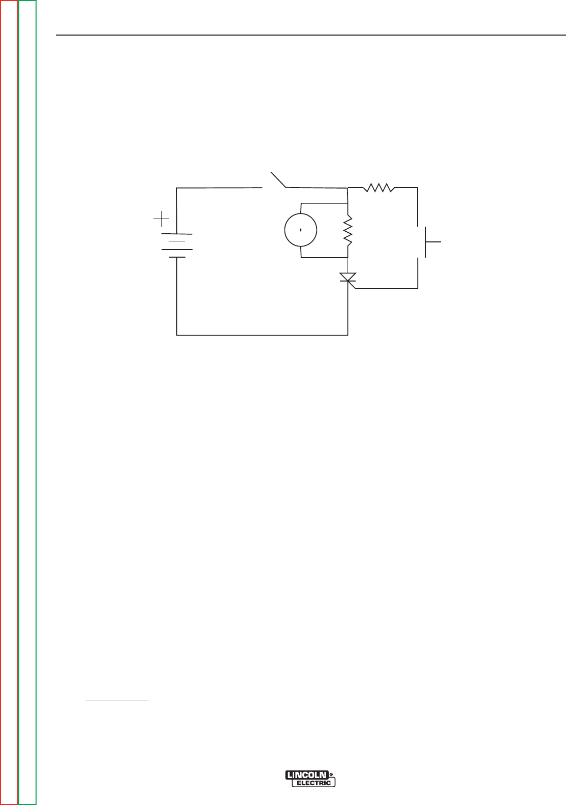
FIGURE F.5 – ACTIVE SCR TEST SETUP
ACTIVE SCR TEST (continued)
TEST PROCEDURE
1. Remove main supply power to the TIG 225
machine.
2. Locate and remove plug J2 from the control
board. See Figure F.3.
3. Perform test procedure as outlined in Figure
F.5. Repeat test for all four SCRs. See Figure
F.6 .
4. Construct the circuit outlined in Figure F.5. One
6V lantern battery can be used. Resistor values
are ±10%. The voltmeter scale should be low,
approximately 0-5 or 0-10 volts.
5. Battery Test - Check the battery by shorting
leads (A) and (C) and then close switch SW-1.
Re-place battery if voltage is less than 4.5 volts.
TROUBLESHOOTING AND REPAIR
F-26 F-26
PRECISION TIG® 225
Return to Section TOC Return to Section TOC Return to Section TOC Return to Section TOC
Return to Master TOC Return to Master TOC Return to Master TOC Return to Master TOC
SW1
R2
SW2
R1
AG
C
V
SCR
under
test
R1= 4 ohms /10 watts
R2= 3 ohms/ 10 watts
6volt
Lantern
Battery
To test SCRs construct the circuit outlined above.
Resistor values are plus or minus ten percent. The
voltmeter scale should be low, approximately 0-5 or
0-10 volts DC.
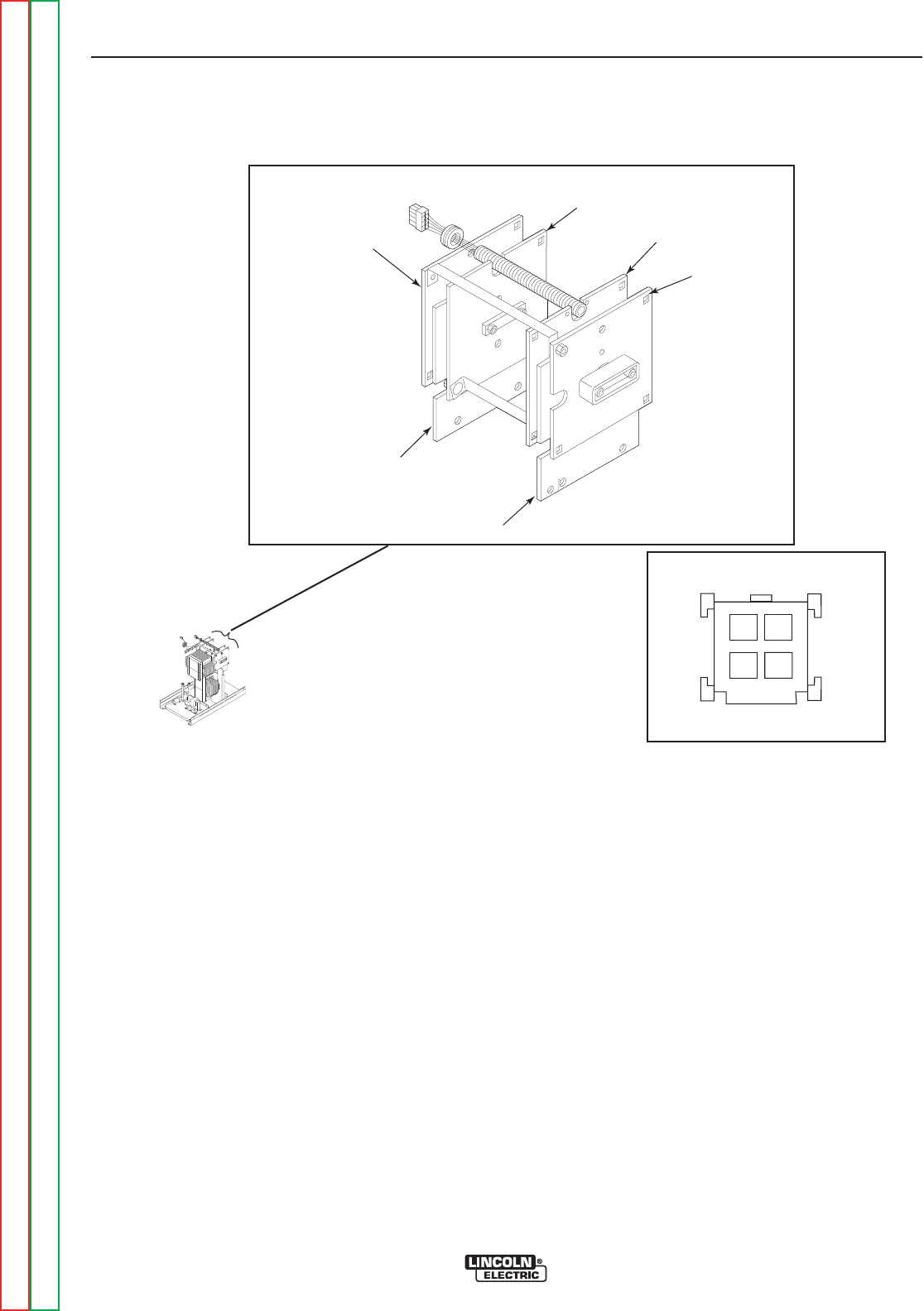
FIGURE F.6 – SCR GATE LOCATIONS
ACTIVE SCR TEST (continued)
TEST PROCEDURE (continued)
6. Connect SCR into the test circuit as shown (A)
lead to anode (C) lead to cathode and (G) lead
to the gate.
7. Close switch SW-1 (switch SW-2 should open),
voltmeter should read zero. If the voltmeter
reads higher than zero the SCR is shorted.
8. With switch SW-1 closed, close switch SW-2 for
two seconds and release. The voltmeter should
read 3 to 6 volts before and after switch SW-2 is
released. If the voltmeter does not read, or
reads only while SW-2 is depressed, the SCR or
battery is defective (repeat Battery Test
Procedure above).
9. Open switch SW-1, disconnect the gate lead (G)
and reverse the (A) and (C) leads on the SCR.
Close switch SW-1. The voltmeter should read
zero. If the voltage is higher than zero, the SCR
is shorted.
10. Replace SCR Bridge Assembly if any SCRs
do not pass the test in Step #3. See SCR
Bridge Assembly Removal and
Replacement.
11. Replace plug J2 into the control board.
12. Replace the case wrap-around cover.
TROUBLESHOOTING AND REPAIR
F-27 F-27
PRECISION TIG® 225
Return to Section TOC Return to Section TOC Return to Section TOC Return to Section TOC
Return to Master TOC Return to Master TOC Return to Master TOC Return to Master TOC
SCR1 ANODE
SCR1 CATHODE/SCR2 ANODE
SCR2 CATHODE
SCR3 CATHODE
SCR4 ANODE
SCR3 ANODE/SCR4 CATHODE
34
2
1
SCR1
SCR4SCR3
SCR2
S24018-4 (INSERTION SIDE)
PLUG J7
SCR GATE LEADS/TEST POINTS

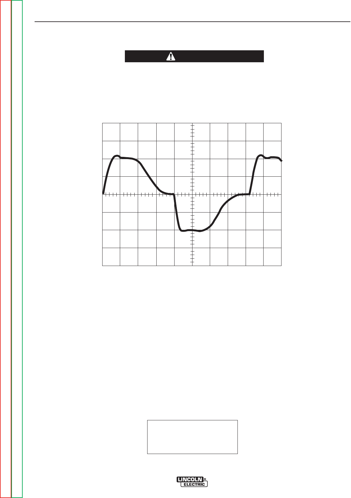
This is the typical AC output voltage
waveform generated from a properly
operating machine. Note that each
vertical division represents 50 volts
and that each horizontal division rep-
resents 2 milliseconds in time.
Note: Scope probes connected at
machine output terminals: (+) probe to
electrode, (–) probe to work.
SCOPE SETTINGS
Volts/Div.....................50V/Div.
Horizontal Sweep .....2 ms/Div.
Coupling.............................DC
Trigger.........................Internal
0 volts
2ms
TROUBLESHOOTING AND REPAIR
F-29 F-29
PRECISION TIG® 225
Return to Section TOC Return to Section TOC Return to Section TOC Return to Section TOC
Return to Master TOC Return to Master TOC Return to Master TOC Return to Master TOC
CAUTION
NORMAL OPEN CIRCUIT VOLTAGE WAVEFORM
AC TIG MODE
HIGH VOLTAGE / HIGH FREQUENCY can damage test equipment.
• Perform all voltage and waveform checks with high frequency circuit OFF.
• Perform High Frequency Disable Procedure.
____________________________________________________________________
50 volts
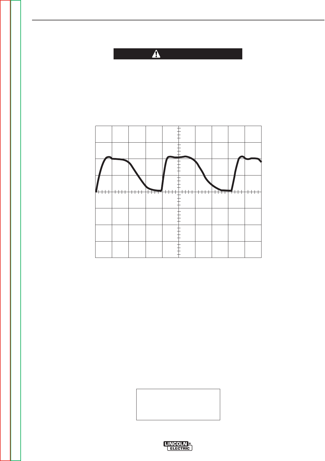
This is the typical DC (+) output volt-
age waveform generated from a prop-
erly operating machine. Note that
each vertical division represents 50
volts and that each horizontal division
represents 2 milliseconds in time.
Note: Scope probes connected at
machine output terminals: (+) probe to
electrode, (–) probe to work.
SCOPE SETTINGS
Volts/Div.....................50V/Div.
Horizontal Sweep .....2 ms/Div.
Coupling.............................DC
Trigger.........................Internal
NORMAL OPEN CIRCUIT VOLTAGE WAVEFORM
DC TIG MODE
TROUBLESHOOTING AND REPAIR
F-30 F-30
PRECISION TIG® 225
Return to Section TOC Return to Section TOC Return to Section TOC Return to Section TOC
Return to Master TOC Return to Master TOC Return to Master TOC Return to Master TOC
CAUTION
HIGH VOLTAGE / HIGH FREQUENCY can damage test equipment.
• Perform all voltage and waveform checks with high frequency circuit OFF.
• Perform High Frequency Disable Procedure.
____________________________________________________________________
0volts
2ms
50 volts
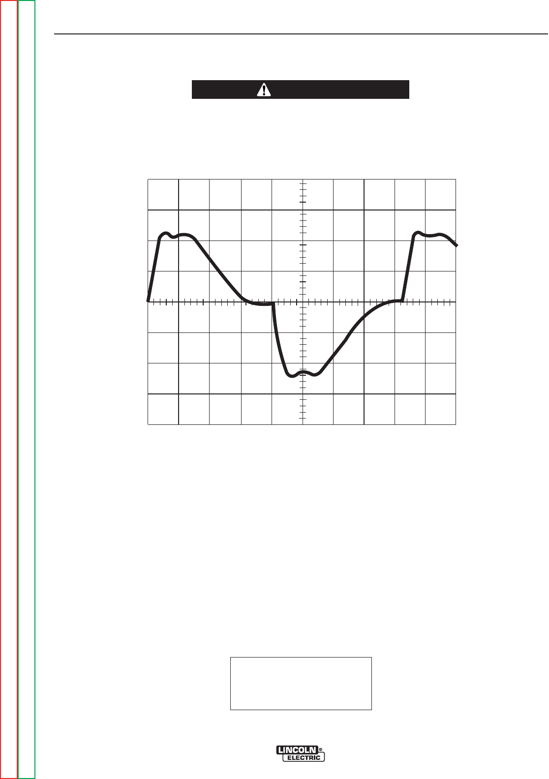
This is the typical AC output voltage
waveform generated from a properly
operating machine. Note that each
vertical division represents 50 volts
and that each horizontal division rep-
resents 2 milliseconds in time.
Note: Scope probes connected at
machine output terminals: (+) probe to
electrode, (–) probe to work.
SCOPE SETTINGS
Volts/Div.....................50V/Div.
Horizontal Sweep .....2 ms/Div.
Coupling.............................DC
Trigger.........................Internal
NORMAL OPEN CIRCUIT VOLTAGE WAVEFORM
AC STICK MODE
TROUBLESHOOTING AND REPAIR
F-31 F-31
PRECISION TIG® 225
Return to Section TOC Return to Section TOC Return to Section TOC Return to Section TOC
Return to Master TOC Return to Master TOC Return to Master TOC Return to Master TOC
CAUTION
HIGH VOLTAGE / HIGH FREQUENCY can damage test equipment.
• Perform all voltage and waveform checks with high frequency circuit OFF.
• Perform High Frequency Disable Procedure.
____________________________________________________________________
0volts
2ms
50 volts

This is the typical DC (+) output volt-
age waveform generated from a prop-
erly operating machine. Note that
each vertical division represents 50
volts and that each horizontal division
represents 2 milliseconds in time.
Note: Scope probes connected at
machine output studs: (+) probe to
electrode, (–) probe to work.
SCOPE SETTINGS
Volts/Div.....................50V/Div.
Horizontal Sweep .....2 ms/Div.
Coupling.............................DC
Trigger.........................Internal
NORMAL OPEN CIRCUIT VOLTAGE WAVEFORM
DC STICK MODE
TROUBLESHOOTING AND REPAIR
F-32 F-32
PRECISION TIG® 225
Return to Section TOC Return to Section TOC Return to Section TOC Return to Section TOC
Return to Master TOC Return to Master TOC Return to Master TOC Return to Master TOC
CAUTION
HIGH VOLTAGE / HIGH FREQUENCY can damage test equipment.
• Perform all voltage and waveform checks with high frequency circuit OFF.
• Perform High Frequency Disable Procedure.
____________________________________________________________________
0 volts
2ms
50 volts
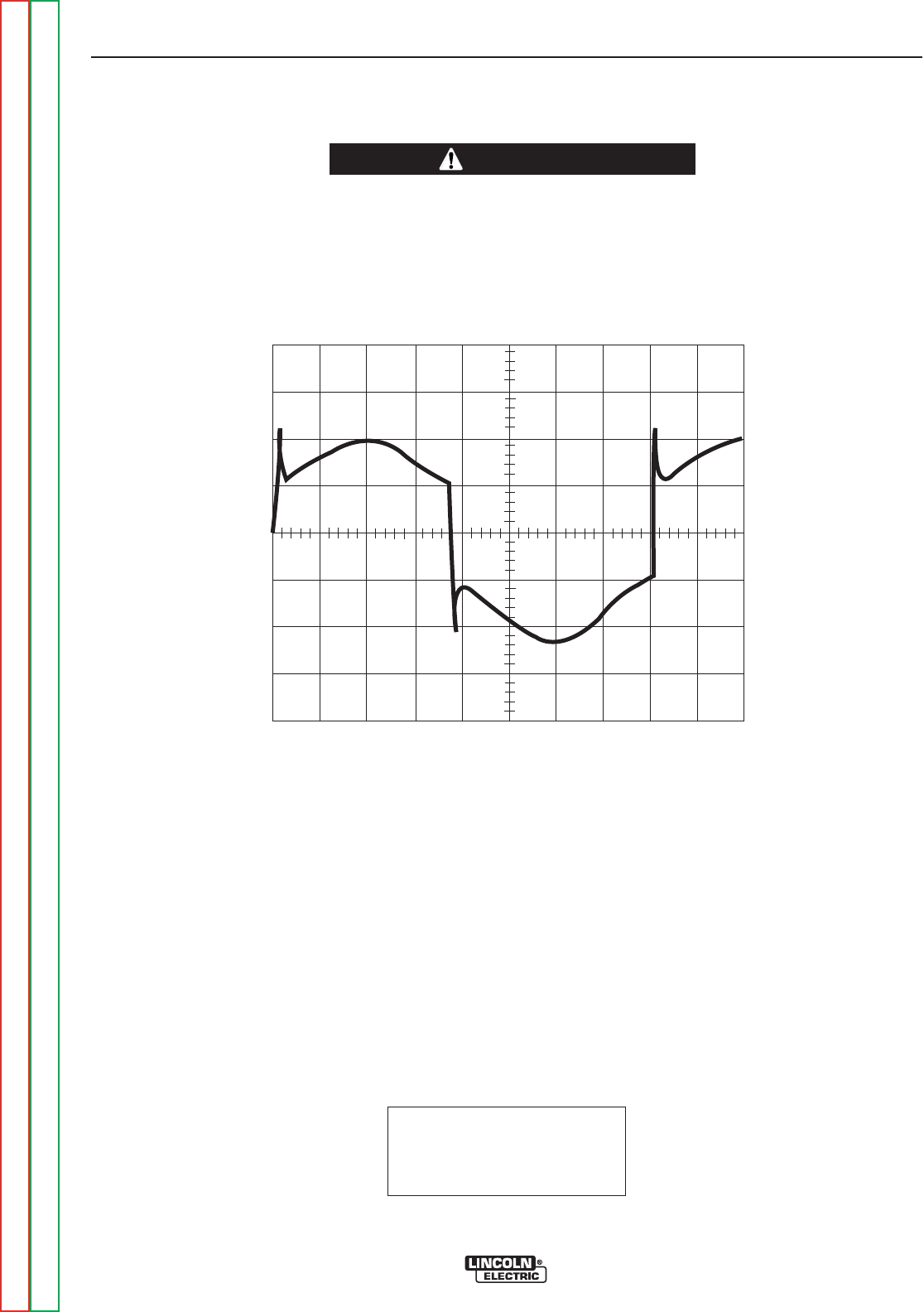
MACHINE LOADED TO 180 AMPS AT
16VDC.
This is the typical AC output voltage wave-
form generated from a properly operating
machine. Note that each vertical division
represents 10 volts and that each horizontal
division represents 2 milliseconds in time.
The machine was loaded with a resistance
grid bank. The grid load meters read 180
amps and 16VDC
Note: Scope probes connected at machine
output terminals: (+) probe to electrode, (–)
probe to work.
SCOPE SETTINGS
Volts/Div.....................50V/Div.
Horizontal Sweep .....2 ms/Div.
Coupling.............................DC
Trigger.........................Internal
TROUBLESHOOTING AND REPAIR
F-33 F-33
PRECISION TIG® 225
Return to Section TOC Return to Section TOC Return to Section TOC Return to Section TOC
Return to Master TOC Return to Master TOC Return to Master TOC Return to Master TOC
TYPICAL OUTPUT VOLTAGE WAVEFORM - MACHINE LOADED
AC TIG MODE
CAUTION
HIGH VOLTAGE / HIGH FREQUENCY can damage test equipment.
• Perform all voltage and waveform checks with high frequency circuit OFF.
• Perform High Frequency Disable Procedure.
____________________________________________________________________
0 volts
2ms
50 volts

MACHINE LOADED TO 180 AMPS AT 16VDC.
This is the typical DC (+) output voltage wave-
form generated from a properly operating
machine. Note that each vertical division repre-
sents 10 volts and that each horizontal division
represents 2 milliseconds in time. The machine
was loaded with a resistance grid bank. The grid
load meters read 180 amps and 16VDC
Note: Scope probes connected at machine out-
put terminals: (+) probe to electrode, (–) probe to
work.
SCOPE SETTINGS
Volts/Div.....................50V/Div.
Horizontal Sweep .....2 ms/Div.
Coupling.............................DC
Trigger.........................Internal
TYPICAL OUTPUT VOLTAGE WAVEFORM - MACHINE LOADED
DC TIG MODE
TROUBLESHOOTING AND REPAIR
F-34 F-34
PRECISION TIG® 225
Return to Section TOC Return to Section TOC Return to Section TOC Return to Section TOC
Return to Master TOC Return to Master TOC Return to Master TOC Return to Master TOC
CAUTION
HIGH VOLTAGE / HIGH FREQUENCY can damage test equipment.
• Perform all voltage and waveform checks with high frequency circuit OFF.
• Perform High Frequency Disable Procedure.
____________________________________________________________________
0volts
2ms
50 volts
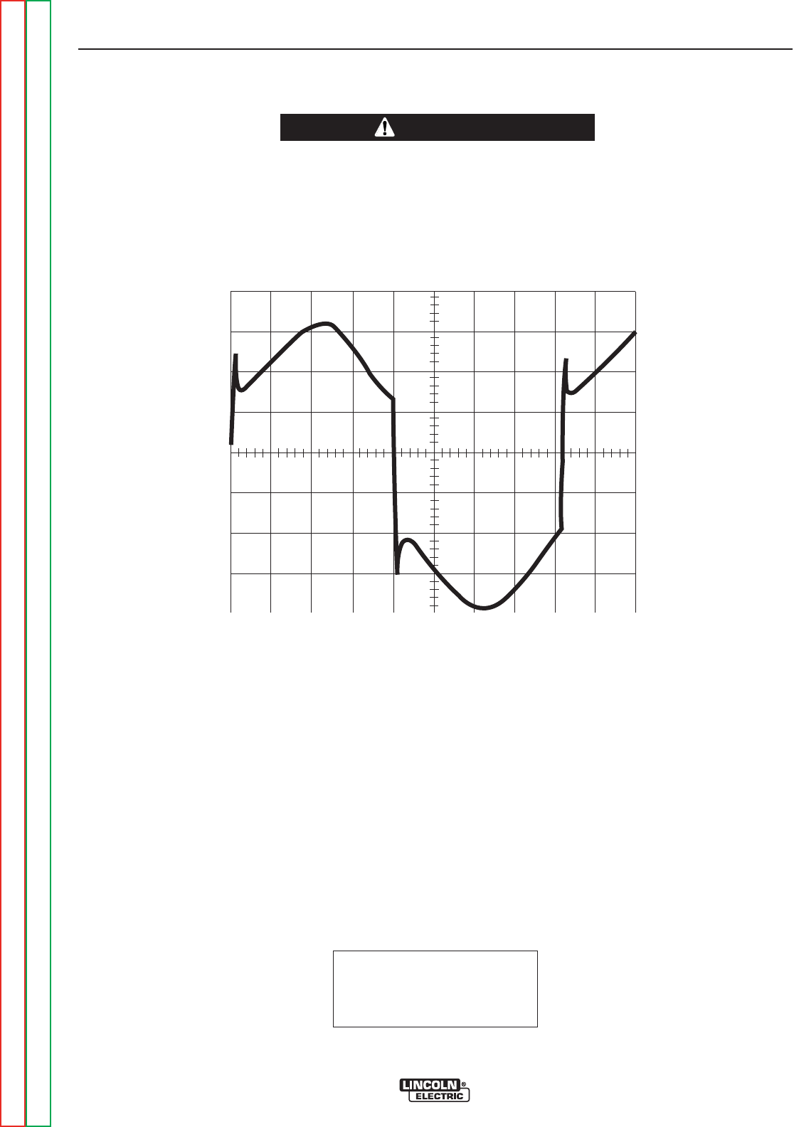
MACHINE LOADED TO 180 AMPS AT
26VDC.
This is the typical AC output voltage wave-
form generated from a properly operating
machine. Note that each vertical division
represents 10 volts and that each horizontal
division represents 2 milliseconds in time.
The machine was loaded with a resistance
grid bank. The grid load meters read 180
amps and 26VDC
Note: Scope probes connected at machine
output terminals: (+) probe to electrode, (–)
probe to work.
SCOPE SETTINGS
Volts/Div.....................50V/Div.
Horizontal Sweep .....2 ms/Div.
Coupling.............................DC
Trigger.........................Internal
TYPICAL OUTPUT VOLTAGE WAVEFORM - MACHINE LOADED
AC STICK MODE
TROUBLESHOOTING AND REPAIR
F-35 F-35
PRECISION TIG® 225
Return to Section TOC Return to Section TOC Return to Section TOC Return to Section TOC
Return to Master TOC Return to Master TOC Return to Master TOC Return to Master TOC
CAUTION
HIGH VOLTAGE / HIGH FREQUENCY can damage test equipment.
• Perform all voltage and waveform checks with high frequency circuit OFF.
• Perform High Frequency Disable Procedure.
____________________________________________________________________
0volts
2ms
50 volts
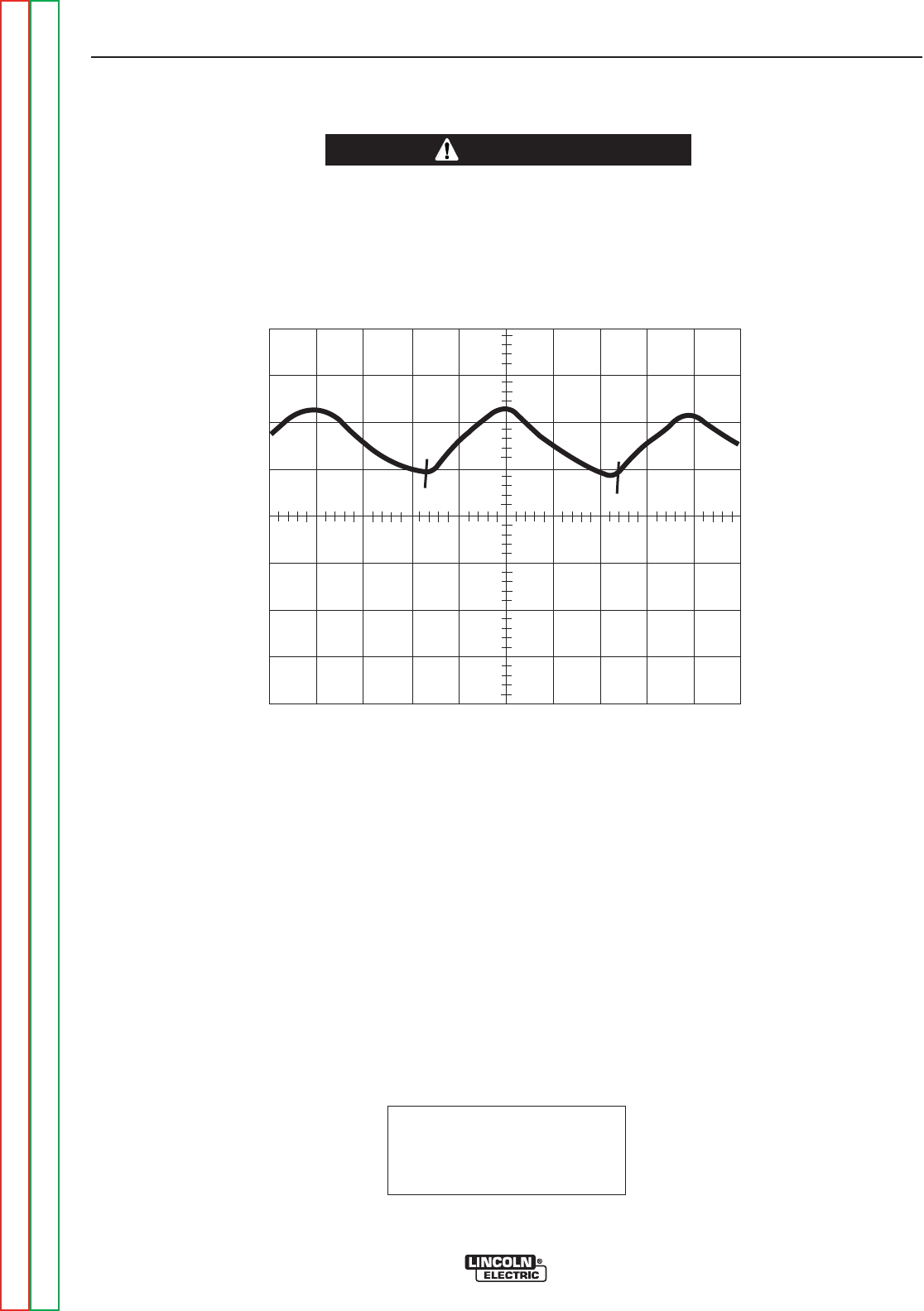
MACHINE LOADED TO 180 AMPS AT
26VDC.
This is the typical AC output voltage waveform
generated from a properly operating machine.
Note that each vertical division represents 10
volts and that each horizontal division repre-
sents 2 milliseconds in time. The machine
was loaded with a resistance grid bank. The
grid load meters read 180 amps and 26VDC
Note: Scope probes connected at machine
output terminals: (+) probe to electrode, (–)
probe to work.
SCOPE SETTINGS
Volts/Div.....................50V/Div.
Horizontal Sweep .....2 ms/Div.
Coupling.............................DC
Trigger.........................Internal
TYPICAL OUTPUT VOLTAGE WAVEFORM - MACHINE LOADED
DC STICK MODE
TROUBLESHOOTING AND REPAIR
F-36 F-36
PRECISION TIG® 225
Return to Section TOC Return to Section TOC Return to Section TOC Return to Section TOC
Return to Master TOC Return to Master TOC Return to Master TOC Return to Master TOC
CAUTION
HIGH VOLTAGE / HIGH FREQUENCY can damage test equipment.
• Perform all voltage and waveform checks with high frequency circuit OFF.
• Perform High Frequency Disable Procedure.
____________________________________________________________________
0volts
2ms
50 volts
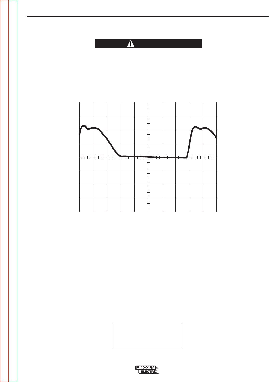
This is NOT the typical DC (+) output
voltage waveform. One output SCR is
not functioning. Note the “gap”in the
waveform. One SCR gate was discon-
nected to simulate an open or non-
functioning output SCR. Note that
each vertical division represents 50
volts and that each horizontal division
represents 2 milliseconds in time.
Note: Scope probes connected at
machine output terminals: (+) probe to
electrode, (–) probe to work.
SCOPE SETTINGS
Volts/Div.....................50V/Div.
Horizontal Sweep .....2 ms/Div.
Coupling.............................DC
Trigger.........................Internal
ABNORMAL OPEN CIRCUIT VOLTAGE - DC TIG MODE
ONE OUTPUT SCR NOT FUNCTIONING
TROUBLESHOOTING AND REPAIR
F-37 F-37
PRECISION TIG® 225
Return to Section TOC Return to Section TOC Return to Section TOC Return to Section TOC
Return to Master TOC Return to Master TOC Return to Master TOC Return to Master TOC
CAUTION
HIGH VOLTAGE / HIGH FREQUENCY can damage test equipment.
• Perform all voltage and waveform checks with high frequency circuit OFF.
• Perform High Frequency Disable Procedure.
____________________________________________________________________
0 volts
2ms
50 volts


Service and repair should be performed by only Lincoln Electric factory trained personnel.
Unauthorized repairs performed on this equipment may result in danger to the technician
or machine operator and will invalidate your factory warranty. For your safety and to avoid
electrical shock, please observe all safety notes and precautions detailed throughout this
manual.
If for any reason you do not understand the test procedures or are unable to perform the
test/repairs safely, contact the Lincoln Electric Service Department for electrical trou-
bleshooting assistance before you proceed. Call 1-888-935-3877.
TEST DESCRIPTION
This procedure will aid the technician in the removal and replacement of the SCR assembly.
MATERIALS NEEDED
5/16” nutdriver
3/8” nutdriver
Needle nose pliers
7/16” Wrench
3/8” Wrench
Slot head screwdriver
Dow Corning 340 Heat Sink compound
SCR BRIDGE ASSEMBLY
REMOVAL AND REPLACEMENT PROCEDURE
TROUBLESHOOTING AND REPAIR
F-39 F-39
PRECISION TIG® 225
Return to Section TOC Return to Section TOC Return to Section TOC Return to Section TOC
Return to Master TOC Return to Master TOC Return to Master TOC Return to Master TOC
WARNING
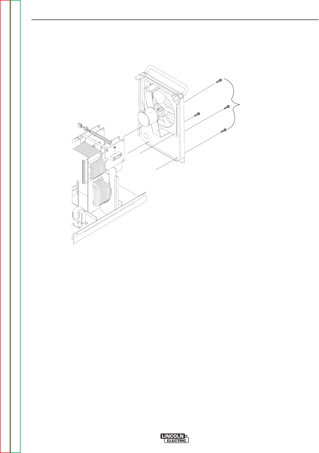
FIGURE F.7 – CASE BACK MOUNTING SCREWS
SCR BRIDGE ASSEMBLY
REMOVAL AND REPLACEMENT PROCEDURE (continued)
PROCEDURE
1. Remove input power to the TIG 225 machine.
2. Using the 3/8” nutdriver remove the case wrap-
around cover.
3. With the slot head screwdriver loosen the input
cable strain relief to allow movement of case
back.
4. Using the 3/8” nutdriver remove the two lower
screws from the case back. See Figure F.7.
5. With the 5/16” nutdriver remove the two screws
holding the case back to the internal divider
panel. See Figure F.7.
6. Remove the gas hose from the gas solenoid
valve.
7. Carefully pull the case back and fan assembly
away to allow access to the SCR Bridge
Assembly. Support the case back so as not to
stress the fan motor leads. It is not necessary
to disconnect the fan motor leads.
8. Using the 5/16” nutdriver remove the two
screws holding the front panel assembly to the
base. See Figure F.8.
TROUBLESHOOTING AND REPAIR
F-40 F-40
PRECISION TIG® 225
Return to Section TOC Return to Section TOC Return to Section TOC Return to Section TOC
Return to Master TOC Return to Master TOC Return to Master TOC Return to Master TOC
REAR PANEL
MOUNTING
SCREWS
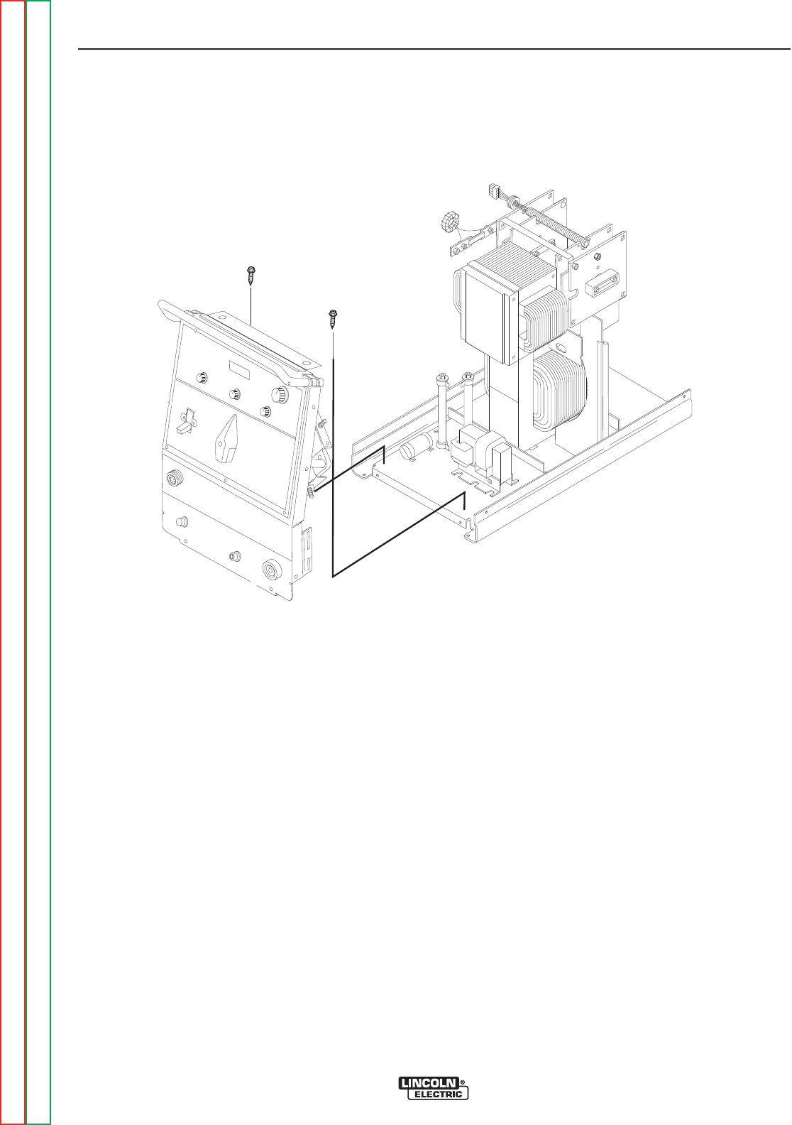
FIGURE F.8 – FRONT PANEL MOUNTING SCREWS
SCR BRIDGE ASSEMBLY
REMOVAL AND REPLACEMENT PROCEDURE (continued)
PROCEDURE (continued)
9. Remove plug J2 from the control board. (See
Figure F.9.) Also remove plug and lead harness
from internal divider panel.
10. Carefully slide the internal divider panel away
a few inches to allow access to the SCR
bridge assembly.
11. Using the 7/16” wrench disconnect the diode
pigtail connection from the polarity switch lead.
See Figure F.10. Cut any necessary cable
ties and remove insulating sleeving.
Note placement of sleeving and cable ties for
reassembly.
12. Using the 7/16” wrench remove the X2 sec-
ondary transformer lead from the left side AC
SCR heat sink.
13. With the 7/16” wrench remove the shunt from
the SCR bridge left side negative heat sink.
14. Using the 7/16” wrench remove the polarity
switch lead from the right side AC SCR heat
sink.
15. Using the 7/16” wrench remove the positive
lead from the right side positive heat sink.
TROUBLESHOOTING AND REPAIR
F-41 F-41
PRECISION TIG® 225
Return to Section TOC Return to Section TOC Return to Section TOC Return to Section TOC
Return to Master TOC Return to Master TOC Return to Master TOC Return to Master TOC
FRONT PANEL
MOUNTING
SCREWS
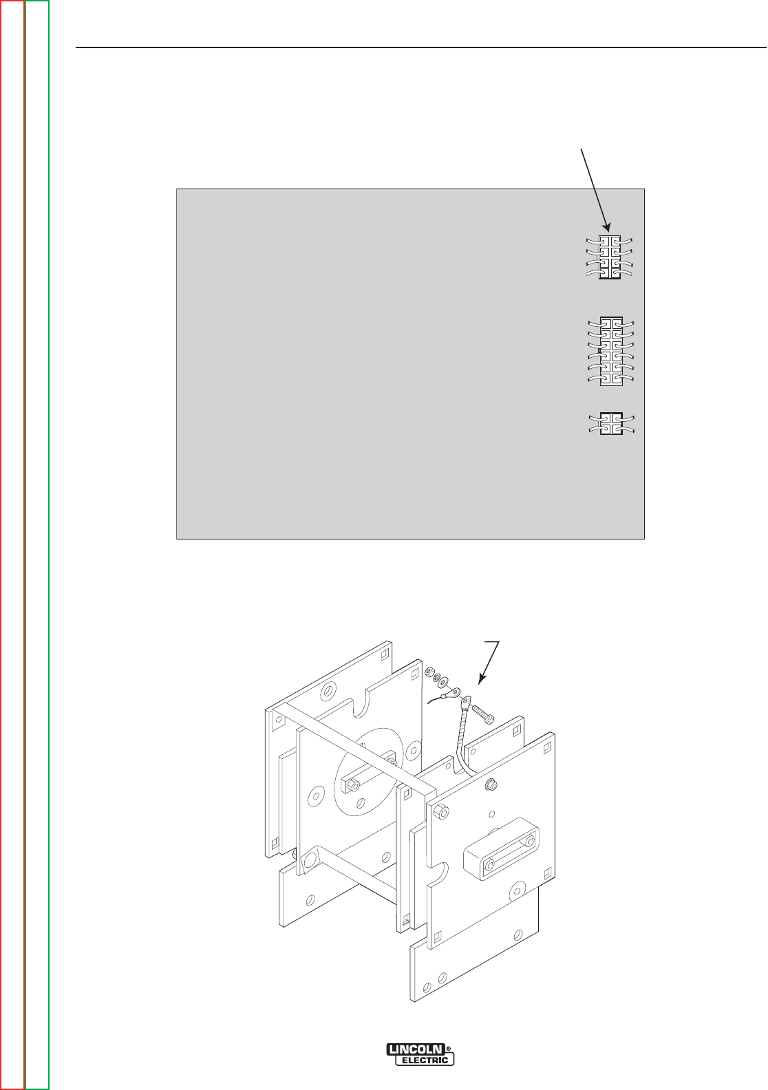
PLUG J2 REMOVED
PRECISION TIG 225 CONTROL
J2
J3
J4
FIGURE F.9 – PLUG J2 ON CONTROL BOARD
SCR BRIDGE ASSEMBLY
REMOVAL AND REPLACEMENT PROCEDURE (continued)
TROUBLESHOOTING AND REPAIR
F-42 F-42
PRECISION TIG® 225
Return to Section TOC Return to Section TOC Return to Section TOC Return to Section TOC
Return to Master TOC Return to Master TOC Return to Master TOC Return to Master TOC
FIGURE F.10 DIODE PIGTAIL CONNECTION TO POLARITY SWITCH LEAD.
DIODE
PIGTAIL
CONNECTION

SCR BRIDGE ASSEMBLY
REMOVAL AND REPLACEMENT PROCEDURE (continued)
16. With the 3/8” wrench remove the four mount-
ing screws holding the SCR bridge assembly
to the main transformer frame. Note insulator
placement.
17. Carefully remove the SCR bridge assembly
from the TIG 225 cutting any necessary cable
ties.
REPLACEMENT PROCEDURE
1. Carefully place the new SCR bridge assembly
in position in the TIG 225.
2. Using the 3/8” wrench install the four mounting
screws taking special care that the insulators
are in the correct positions.
USE DOW CORNING 340 HEAT SINK COM-
POUND ON ALL ALUMINUM CONNECTIONS
3. Assemble the positive lead to the right side pos-
itive heat sink.
4. Assemble the lead from the polarity switch to
the right side AC heat sink. Note: Also connect
lead #216
5. Assemble the shunt to the SCR bridge left side
negative heat sink.
6. Assemble the X2 secondary transformer lead to
the left side AC SCR heat sink. Note: Also con-
nect lead #217
7. Assemble the diode pigtail lead to the polarity
switch lead. See Figure F.10. Besureto
replace sleeving and secure with cable ties.
Position with harness and secure with cable
ties.
8. Replace any previously removed cable ties.
9. Position the internal divider panel and secure
with the screws previously removed.
10. Install the J2 plug into the control board and
position the harness in the internal divider
panel.
11. Position and install the case back and secure
with the screws previously removed.
12. Install the gas hose onto the solenoid valve.
13. Tighten the input cable strain relief.
14. Assemble the case wrap-around cover.
TROUBLESHOOTING AND REPAIR
F-43 F-43
PRECISION TIG® 225
Return to Section TOC Return to Section TOC Return to Section TOC Return to Section TOC
Return to Master TOC Return to Master TOC Return to Master TOC Return to Master TOC


Service and repair should be performed by only Lincoln Electric factory trained personnel.
Unauthorized repairs performed on this equipment may result in danger to the technician
or machine operator and will invalidate your factory warranty. For your safety and to avoid
electrical shock, please observe all safety notes and precautions detailed throughout this
manual.
If for any reason you do not understand the test procedures or are unable to perform the
test/repairs safely, contact the Lincoln Electric Service Department for electrical trou-
bleshooting assistance before you proceed. Call 1-888-935-3877.
TEST DESCRIPTION
This procedure will aid the technician in the removal and replacement of the polarity switch.
MATERIALS NEEDED
3/8” Nutdriver
1/2” Wrench
7/16” Wrench
Phillips head screwdriver
5/64” Allen type Wrench
Needle nose pliers
Slot head screwdriver (2 required)
Wiring diagram
POLARITY SWITCH
REMOVAL AND REPLACEMENT PROCEDURE
TROUBLESHOOTING AND REPAIR
F-45 F-45
PRECISION TIG® 225
Return to Section TOC Return to Section TOC Return to Section TOC Return to Section TOC
Return to Master TOC Return to Master TOC Return to Master TOC Return to Master TOC
WARNING

POLARITY SWITCH
REMOVAL AND REPLACEMENT PROCEDURE (continued)
REMOVAL PROCEDURE
1. Remove the input power to the TIG 225
machine.
2. Using the 3/8” nutdriver remove the case wrap-
around cover.
3. Using the 3/32” Allen type wrench remove the
output control knob.
4. Using the Phillips head screwdriver remove the
screw from the polarity switch handle.
5. With the 2 slot head screwdrivers carefully pry
the polarity switch handle from the shaft.
6. Remove the five plastic snap rivets holding the
name plate to the case front. These can be
removed by gently prying at the rivet between
the name plate and the case front.
7. Remove the name plate.
8. With the 1/2” wrench remove the “positive” flex
lead from the polarity switch. See wiring dia-
gram. Label lead and connection point for
reassembly.
9. With the 1/2” wrench remove the “AC” flex lead
from the polarity switch. This lead connects to
the AC plate on the SCR bridge. See wiring
diagram. Label lead and connection point for
reassembly.
10. Using the 1/2” wrench remove the flex lead
from the rear gang of the polarity switch. This
lead connects to the D1 diode on the SCR
bridge. See wiring diagram. Label lead and
connection point for reassembly.
11. Using the 1/2” wrench remove the flat copper
lead from the polarity switch. This lead con-
nects to the high frequency transformer coil
and the by-pass board. See wiring
diagram. Label lead and connection point for
reassembly.
12. Using the 1/2” wrench remove the other flat
copper lead from the polarity switch. This lead
connects to the lower terminal on the by-pass
board and the “work” lead. See wiring dia-
gram. Label lead and connection point for
reassembly.
13. Using the 1/2” wrench remove the choke lead
from the polarity switch. See wiring diagram.
Label lead and connection point for reassem-
bly.
14. With the 1/2” wrench remove the X1 sec-
ondary lead from the polarity switch. See
wiring diagram. Label lead and connection
point for reassembly.
15. With the 7/16” wrench remove the two nuts
and washers that hold the polarity switch to
the front panel.
16. Carefully rotate the polarity switch assembly to
gain access to the micro-switch.
17. Carefully unsolder the two leads (#311 and
#312) from the micro-switch located on the
polarity switch assembly. See wiring diagram.
Label leads and connection points for
reassembly.
18. Carefully remove the polarity switch assembly
from the machine.
TROUBLESHOOTING AND REPAIR
F-46 F-46
PRECISION TIG® 225
Return to Section TOC Return to Section TOC Return to Section TOC Return to Section TOC
Return to Master TOC Return to Master TOC Return to Master TOC Return to Master TOC

POLARITY SWITCH
REMOVAL AND REPLACEMENT PROCEDURE (continued)
REPLACEMENT PROCEDURE
1. Carefully position the new polarity switch in
position on the front panel. Make certain the
micro-switch is assembled to the polarity switch
correctly.
2. Solder leads #311 and #312 to the micro -
switch.
3. Assemble and tighten the two nuts and washers
that hold the polarity switch to the front panel.
4. Assemble the X1 secondary lead to the polarity
switch. Make certain washers are in place and
the nut is tight.
5. Assemble the choke lead to the polarity switch.
Make certain washers are in place and the nut
is tight.
6. Assemble the flat copper leads to the polarity
switch. Make certain they are connected to the
proper terminals and the nuts are tightened.
7. Assemble the flex lead from diode D1 to the
rear gang of the polarity switch. Make certain
washers are in place and the nut is tight.
8. Assemble the flex lead from the AC bridge
plate to the polarity switch. Make certain
washers are in place and the nut is tight.
9. Assemble the “positive” flex lead to the polarity
switch. Make certain washers are in place and
the nut is tight.
10. Clear the leads and check for “shorted” or
“grounded” leads.
11. Position the name plate and fasten to the front
with the previously removed snap rivets.
12. Assemble the polarity switch handle in place
with the Phillips head screw and check for cor-
rect switch operation.
13. Using the Allen type wrench replace the output
control knob.
14. Replace the case wrap-around cover.
TROUBLESHOOTING AND REPAIR
F-47 F-47
PRECISION TIG® 225
Return to Section TOC Return to Section TOC Return to Section TOC Return to Section TOC
Return to Master TOC Return to Master TOC Return to Master TOC Return to Master TOC


Service and repair should be performed by only Lincoln Electric factory trained personnel.
Unauthorized repairs performed on this equipment may result in danger to the technician
or machine operator and will invalidate your factory warranty. For your safety and to avoid
electrical shock, please observe all safety notes and precautions detailed throughout this
manual.
If for any reason you do not understand the test procedures or are unable to perform the
test/repairs safely, contact the Lincoln Electric Service Department for electrical trou-
bleshooting assistance before you proceed. Call 1-888-935-3877.
TEST DESCRIPTION
This procedure will aid the technician in the removal and replacement of the high voltage
transformer.
MATERIALS NEEDED
3/8” Nutdriver
Phillips head screwdriver
Needle nose pliers
Wire cutters
HIGH VOLTAGE TRANSFORMER
REMOVAL AND REPLACEMENT PROCEDURE
TROUBLESHOOTING AND REPAIR
F-49 F-49
PRECISION TIG® 225
Return to Section TOC Return to Section TOC Return to Section TOC Return to Section TOC
Return to Master TOC Return to Master TOC Return to Master TOC Return to Master TOC
WARNING
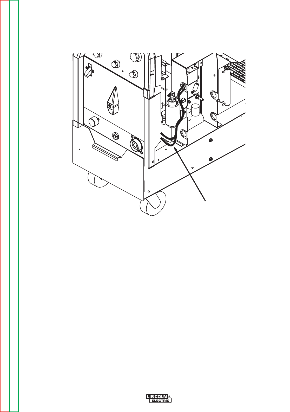
FIGURE F.11 – SECONDARY LEADS AT HIGH FREQUENCY STARTER BOARD
HIGH VOLTAGE TRANSFORMER
REMOVAL AND REPLACEMENT PROCEDURE (continued)
REMOVAL PROCEDURE
1. Remove input power to the TIG 225 machine.
2. Using the 3/8” nutdriver remove the case wrap-
around cover.
3. With the needle nose pliers remove the two
secondary leads from the quick-connects on
the high frequency arc starter board assembly.
See Figure F.11.
4. Disconnect the in-line splice quick connect from
one primary lead to lead #231A. Cut any nec-
essary cable ties.
5. Remove the lead splice from the other primary
lead that is connected to lead #236 and the C4
capacitor. See wiring diagram. Cut any neces-
sary cable ties.
6. Using the phillips head screwdriver remove the
front mounting screws from the base of the high
voltage transformer. Take note of insulator
placement for reassembly. NOTE: On some
machines the mounting screw configuration
may be different.
7. With phillips head screwdriver loosen the two
rear mounting screws.
8. Carefully slide the transformer forward and
remove from the TIG 225 machine.
TROUBLESHOOTING AND REPAIR
F-50 F-50
PRECISION TIG® 225
Return to Section TOC Return to Section TOC Return to Section TOC Return to Section TOC
Return to Master TOC Return to Master TOC Return to Master TOC Return to Master TOC
TRANSFORMER
SECONDARY
LEADS

FIGURE F.12 – HIGH VOLTAGE TRANSFORMER MOUNTING INSULATORS
HIGH VOLTAGE TRANSFORMER
REMOVAL AND REPLACEMENT PROCEDURE (continued)
REPLACEMENT PROCEDURE
1. Carefully position the new high voltage trans-
former in place in the two rear mounting insula-
tors. See Figure F.12.
2. Install the front mounting insulators and mount-
ing screw.
3. Using the phillips head screwdriver tighten all
four mounting screws making certain the insu-
lators are positioned correctly.
4. Reconnect the two primary leads.
5. Reconnect the two secondary leads to the high
frequency arc starter board assembly.
6. Replace any previously removed cable ties.
7. Replace the case wrap-around cover.
TROUBLESHOOTING AND REPAIR
F-51 F-51
PRECISION TIG® 225
Return to Section TOC Return to Section TOC Return to Section TOC Return to Section TOC
Return to Master TOC Return to Master TOC Return to Master TOC Return to Master TOC
FRONT MOUNTING
INSULATORS
SLOTTED REAR
MOUNTING INSULATORS
NOTE: On some machines the
mounting screw configuration may be
different.


Service and repair should be performed by only Lincoln Electric factory trained personnel.
Unauthorized repairs performed on this equipment may result in danger to the technician
or machine operator and will invalidate your factory warranty. For your safety and to avoid
electrical shock, please observe all safety notes and precautions detailed throughout this
manual.
If for any reason you do not understand the test procedures or are unable to perform the
test/repairs safely, contact the Lincoln Electric Service Department for electrical trou-
bleshooting assistance before you proceed. Call 1-888-935-3877.
TEST DESCRIPTION
This procedure will aid the technician in the removal and replacement of the main transformer
and choke assembly.
MATERIALS NEEDED
3/8” Nutdriver
1/2” Wrench
Wire cutters
MAIN TRANSFORMER AND OUTPUT CHOKE ASSEMBLY
REMOVAL AND REPLACEMENT PROCEDURE
TROUBLESHOOTING AND REPAIR
F-53 F-53
PRECISION TIG® 225
Return to Section TOC Return to Section TOC Return to Section TOC Return to Section TOC
Return to Master TOC Return to Master TOC Return to Master TOC Return to Master TOC
WARNING

MAIN TRANSFORMER AND OUTPUT CHOKE ASSEMBLY
REMOVAL AND REPLACEMENT PROCEDURE (continued)
REMOVAL PROCEDURE
1. Remove input power to the TIG 225 machine.
2. Perform the SCR Bridge Assembly Removal
Procedure.
3. Unsolder the two 115VAC leads and leads
B231 and B232 from the main transformer
leads. Label leads for reassembly. See wiring
diagram.
4. Unsolder leads W201 and W204 from the main
transformer leads. Label leads for reassembly.
See wiring diagram.
5. Unsolder leads R209 and U210 from the main
transformer leads. Label leads for reassembly.
See wiring diagram.
6. Using the 1/2” wrench remove the shunt
assembly from the choke lead.
7. With the 3/8” wrench remove the H1, H2 or H3
lead from the input power switch. See wiring
diagram. Label the leads and connection points
for reassembly. Cut any necessary cable ties.
8. Remove plug J3 from the control board and
push through the interior divider panel.
9. Using the 1/2” wrench remove the choke lead
from the polarity switch. See wiring diagram.
Label lead and connection point for reassembly.
10. With the 1/2” wrench remove the X1 sec-
ondary lead from the polarity switch. See
wiring diagram. Label lead and connection
point for reassembly.
11. With the 1/2” wrench remove the four nuts and
lock washers from the transformer mounting
bolts at the base of the machine.
12. Carefully hoist the transformer/ choke assem-
bly clear of the base. Clear all leads.
REPLACEMENT PROCEDURE
1. Position the new transformer/choke assembly
onto the base and mounting bolts.
2. Assemble the four nuts and washers to the
mounting bolts on the base of the machine.
3. Assemble the X1 secondary lead to the polarity
switch.
4. Assemble the choke lead to the polarity switch.
5. Install the J3 plug into the control board.
6. Assemble the H1, H2 or H3 lead onto the input
power switch. Insulate and secure the unused
lead (H2 or H3).
7. Assemble the shunt assembly to the choke
lead.
8. Solder leads R209 and U210 to the main trans-
former leads. See wiring diagram. Insulate
connections.
9. Solder leads W201 and W204 to the main
transformer leads. See wiring diagram.
Insulate connections.
10. Solder the two 115VAC leads and leads B231
and B232 to the main transformer leads. See
wiring diagram. Insulate connections.
11. Replace any previously removed cable ties.
Clear leads and check for “shorts” or
“grounds”.
12. Perform the SCR Bridge Assembly
Replacement Procedure.
TROUBLESHOOTING AND REPAIR
F-54 F-54
PRECISION TIG® 225
Return to Section TOC Return to Section TOC Return to Section TOC Return to Section TOC
Return to Master TOC Return to Master TOC Return to Master TOC Return to Master TOC

Return to Section TOC Return to Section TOC Return to Section TOC Return to Section TOC
Return to Master TOC Return to Master TOC Return to Master TOC Return to Master TOC
NOTES
F-55 F-55
PRECISION TIG® 225
RETEST AFTER REPAIR
Should a machine under test be rejected for any reason requiring the removal of any mechanical part that could
affect the machine’s electrical characteristics, or if any electrical components are repaired or replaced, the machine
must be retested.
Input Volts/Hertz Maximum Idle Amps
208/60 2.70 Amps
230/60 3.00 Amps
Stick Mode OCV AC 70 - 75VAC
DC 55 - 66VDC
TIG Mode OCV AC 70 - 80VAC
DC 60 - 66VDC
DC TIG Mode 5 Amps @ 12 Volts
DC TIG Mode 225 Amps @ 29 Volts
MAXIMUM ACCEPTABLE OUTPUT VOLTAGE -
AT MINIMUM OUTPUT SETTINGS
MINIMUM ACCEPTABLE OUTPUT VOLTAGE -
AT MAXIMUM OUTPUT SETTINGS
RECOMMENDED METERS FOR MACHINE OUTPUT TESTS
VOLTMETER: AC and DC True RMS Meter - Fluke 8922A or equivalent
AMMETER: Columbia Type AX AC or DC Tong Ammeter
IMPORTANT: IF OTHER TYPE METERS ARE USED RESULTS MAY NOT BE ACCURATE.
INPUT IDLE AMPS
OPEN CIRCUIT VOLTAGES


TABLE OF CONTENTS - DIAGRAM SECTION
G-1 G-1
Return to Master TOC Return to Master TOC Return to Master TOC Return to Master TOC
PRECISION TIG® 225
ElectricalDiagrams .....................................................................G-1
WiringDiagram(G5646) ...............................................................G-2
EntireMachineSchematic(G5647).......................................................G-3
ControlPCBoardSchematic#1(G5640) ..................................................G-4
ControlPCBoardSchematic#2(G5640) ..................................................G-5
ControlPCBoardSchematic#3(G5640) ..................................................G-6
ControlPCBoardAssembly#1(G5641)...................................................G-7
ControlPCBoardAssembly#2(G5641)...................................................G-8
ByPassPCBoardSchematic(S22530) ...................................................G-9
ByPassPCBoardAssembly(L10121) ...................................................G-10
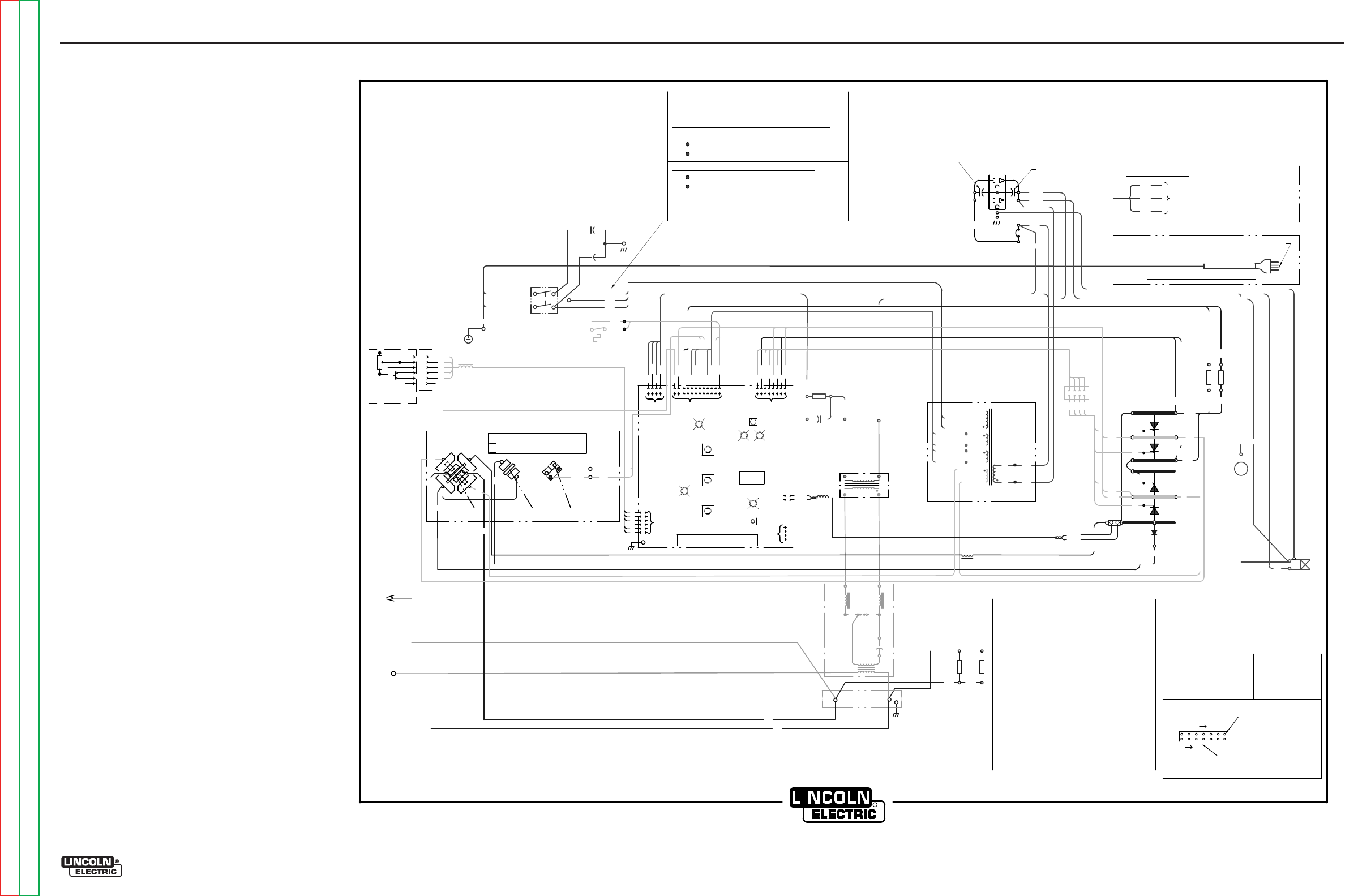
ELECTRICAL DIAGRAMS G-2
PRECISION TIG® 225
WIRING DIAGRAM - COMPLETE MACHINE - ALL CODES (G5646)
R
CLEVELA
N
D , O
HI
OG5646 A
S
CR
4
S
CR
2
S
CR
1
D
C
B
A
REAR GANG
L1
ELEC
TRO
DE
T3
NC
NO
MI
CRO
-SWI
TC
H
T2
L2
L3
C3
S
CR
3
H1
H
G
311A
312A
OP
EN
CLOS
ED
CLOS
ED
G4
216
G3
218
G2
G1
217
220
AC
EF
PC BO
ARD
CO
NT
R
OL PC BOA
RD
D1
S2
SV1
GAS
V
AL
VE
S2
A
BYPA
S
S/
STABI
LIZER
H1
X1
X2
R 222
W 221
WO
RK
R2
ARC
STARTER
A
S'BLY
237
C4
R3
235
J3
236A
SP
ARK
GAP
284A
285A
AC
DC+
DC-
A-C, D-E
,
B-F
B-D, C-E
,
A-F
,
G-H
B-D, A-
E,
C-F,
G-H
POL
AR
ITY SWI
TCH
M
ICR
OSWI
TCH
(
REAR V
IEW,
SHOWN IN AC POSITION
)
115V
AC
18V
AC
18V
AC
78V
AC
T1
POL
ARITY
SWITCH
H3
H2
H3 (
HIGH
)
H2 (LO
W)
L4
POS
X4
X5
X3
X6
X7
X8
C2
C1
201
204
209
210
231
232
AUTO
BALA
N
CE
LED
PULSE
F
REQ
LED
AC
BALA
N
CE
CO
NTRO
L
PULSE
CO
NTRO
L
POS
TFLO
W
CO
NTRO
L
ST
IC
K LE
D
TI
GLED
DIGITAL
DISPLAY
THER
M
AL
LED
OUTPUT
CO
NTRO
L
M
ODE
SW
ITCH
B
(L1
)
W
(L2
)
POWER
SWITCH
S1
G
FAN
115V
AC
+
()
()
_
DC
115V
AC
238
239
210
209
201
313
314
1
2
3
4
65
7
11
12
R222
W 221
1
2
89
10
RECEPTACL
E
C
A
BB
10K
A-B
F
E
D
C
AT
MI
NI
MUM
D
REMO
TE
TM
AMPTROL
OPTIONAL
A
E
REMO
TE
J2
J1
A1
J5
2
3
4
5
6
C
B
D
E
216A
240
L5
204
236
231A
260
R4
220A
245
R5
218A
244
TRI
GGER
POWER
R1
284B
285B
285
284
AC
X2
F
RON
T
GANG
RG
G
G
Y
220A
218A
231B
J4
311
312
245 244
216A
240
314
S4
CHOKE
313
SEE RATING
PLAT
EFOR SPECIFIC VOLTAG
ES
230 or 40
0-415 or 575 V
OLT CONNECTION
H1 and H3 (
HIGH
)TO PO
W
ER S
W
ITCH.
208 or 38
0 or 460
VOLT
CON
NECTION
H1 and H2 (LO
W
) TO PO
W
ER S
W
ITCH.
H3 NOT CON
NECTED; INSULATE.
H2 NOT CON
NECTED; INSULATE.
C1 AND C2 MUST AL
W
AYS BE CONNECTED
ACROSS TRANSFORMER PRIMARIES
VOLTAGE RECONNECTION
(AS SHO
W
N & AS SHIP
PED F
ROM FACTORY
)
B-BLACK R-RED
G-GREEN W-WH
IT
E
LEAD COLORIN
G
COD
E:
CONNE
CTO
R
PI
NNU
MB
ER
S:
VIEW
OF
CONNE
CTO
R
O
N
P
C
BO
ARD
123 7
8
14
LATC
H
EX
AM
PLE: THIS I
S PI
N
7
OF
CONNE
CTO
R
J4
COMPONEN
T
VALUE
UN
IT
S:
RE
SIS
TOR
S:
CAPAC
IT
OR
S:
OHM
S/
WATTS
MFD
/V
OLTS
J4
ELECTRICAL SYMBOL
S P
ER
E1
53
7.
4321
235
260
G4 220
G2 G1
216 G3
218 217
1
2
3
45
6
7
8
DC
POS
SHUN
T
X1
236 232A
INPU
T
PLUG
(
208V/230V ONLY)
TO GROUND PER
NATIONAL ELECTRIC
CODE
285
284
G4
G2
1
2
3
4
G3
G1
P7
J7
1
2
3
J6
4
CO
NN
ECT
GR
EEN
LE
A
DT
OG
RO
UN
DPE
R
NA
TIO
NA
L
A
ND
LO
CA
L EL
ECT
RIC
A
L C
ODE
CO
NN
ECT
BL
A
CK
A
ND WHITE
LE
A
DS
TO S
UPP
LY
CIRCUI
T
B
(L1
)
W
(L2
)
G
380V AND ABOVE
208V/230V ONLY
311
312
115
VAC
231A
232
CB1
233
232A
231B
231
C1,C2 BY-PASS CAPACITORS, .0047/250VAC
C3
HIGH VOLTAGE CAPACITOR, .0025/10kV
C4
PHASE SHIFT CAPACITOR, 15/250VAC
C5,C6 BY-PASS CAPACITORS, .22/400VDC
CB1
20A CIRCUIT BREAKER(208V/230V ONLY)
6A CIRCUIT BREAKER (380V AND ABOVE)
D1
FREE WHEELING DIODE
L1
OUTPUT INDUCTOR (CHOKE)
L2,L3 HIGH FREQUENCY INDUCTORS
L4,L5 RF TOROID CHOKES
R1,R2 HOLDING RESISTORS, 100/100W
R3
PHASE SHIFT RESISTOR, 200/100W
R4,R5 MICRO START RESISTORS, 12/100W
S1
INPUT POWER SWITCH
S2
POLARITY SWITCH
S2A
MICROSW ITCH ON POLARITY S W ITCH
S4
MAIN CHOKE THERMOSTAT
SCR1,2,3,4 MAIN POWER SCR'S
SV1
GAS SOLENOID VALVE, 115VAC
T1
MAIN TRANSFORMER
T2
HIGH VOLTAGE TRANSFORMER
T3
HIGH FREQUENCY TRANSFORMER
RECE
PTAC
LE
(BACK
V
IEW)
C5
C6
G-2
NOTE: This diagram is for reference only. It may not be accurate for all machines covered by this manual. The wiring diagram specific to your code is pasted inside one of the enclosure panels of your machine.
Return to Section TOC Return to Section TOC Return to Section TOC Return to Section TOC
Return to Master TOC Return to Master TOC Return to Master TOC Return to Master TOC
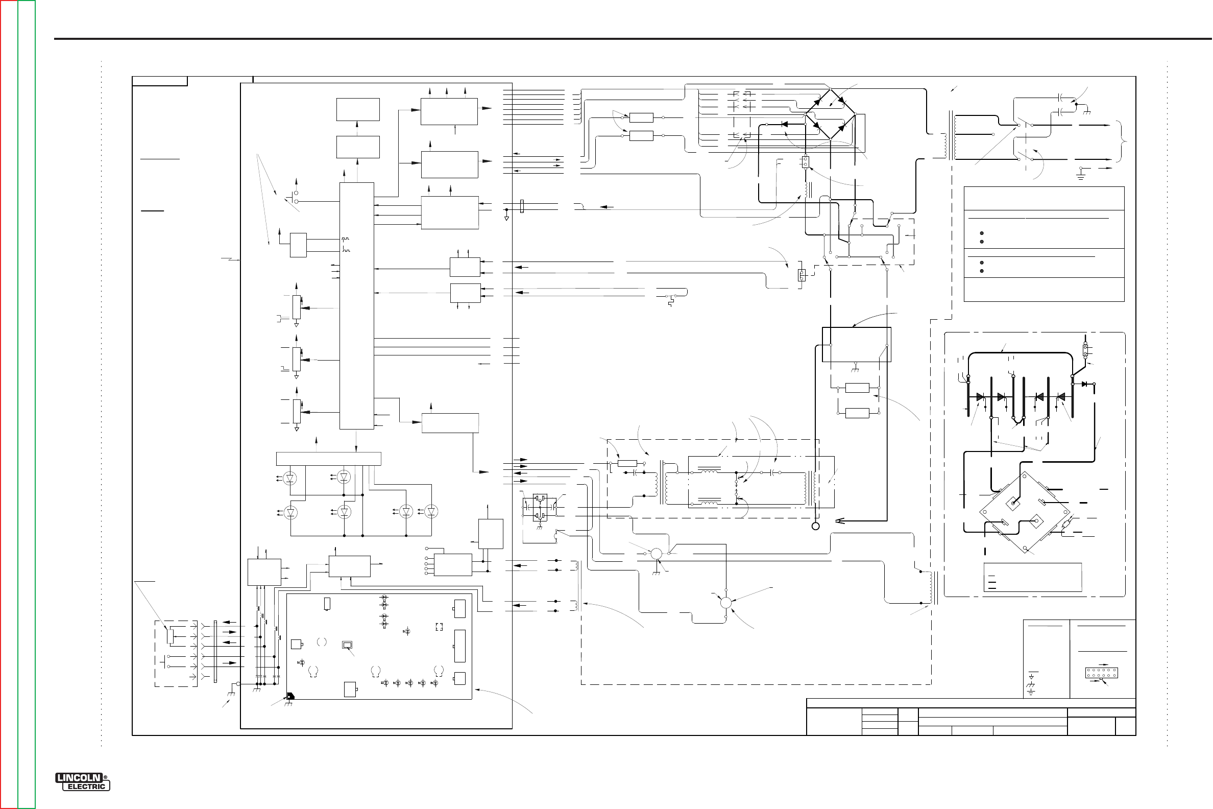
Return to Section TOC Return to Section TOC Return to Section TOC Return to Section TOC
Return to Master TOC Return to Master TOC Return to Master TOC Return to Master TOC
ELECTRICAL DIAGRAMS G-3
PRECISION TIG® 225
SCHEMATIC - COMPLETE MACHINE - ALL CODES (G5647)
EN-170
S
O
LIDE
D
G
E
E
NGI
N
EE
RI
NG
CO
NT
RO
LLE
D
MA
NU
FA
CT
URE
R:
No R
EL
EASE
DF
R
OM
X
A.02
G5647
Precision Tig 225
MACHINE SCHEMATIC
NONE
G4588
Jbarto
R
Sam
ode
ll
Ap
prove
D
RAWN
BY:
DESIG
N
I
NFO
RMATI
ON
ENG
I
NEER:
AP
PRO
VED
:
REFERENCE:
EQ
UIP
M
ENT
TYPE:
SUBJECT:
SCA
L
E:
MATERI AL
DISPOS
IT
ION:
APPROVAL
DATE:
PROJECT
NUMBER:
NA C
RM38254
1
PAGE ___ OF
___
1
DO
C
UM
E
NT
N
UM
BE
R:
DOCUMENT
REVISION:
THIS DOCUMENT CONTAINS PROPRIETAR
Y
INFORMATION OWNED B
Y
LINCOLN GLOBA
L, INC.
AND MA
Y
NOT BE DUPLICATED, COMMUNICATED
TO O
THER PARTIES OR US
ED FOR
AN
Y
PURPOS
E WITHOU
T
THE EXPRES
S WRIT
TEN PERMISSION
OF LINCOLN GLOBAL, INC.
PRO
PRIETARY & C
ONFIDENTIAL:
A
T
HE I
NF
ORMA
T
IO
N
ON
T
HIS
PRIN
T
IS
F
OR
RE
F
ER
ENC
E
ON
LY.
C
O
MPON
EN
T
S
AND
CIRCUI
T
RY
MA
Y
BE
DIFFER
ENT
F
RO
M
AN
AC
T
UAL
M
ACHIN
E.
06/20/2006
CHANG
E
D
ET
AIL:
G5647
LE
A
D
C
OL
O
R
COD
E:
B-
BL
AC
K
O
R
GRAY
G-
GREEN
O-
ORANGE
R-
RE
D
O
R
PI
NK
U-
BL
UE
W-
W
HIT
E
Y-
Y
ELL
OW
C
OM
PONE
NT
V
AL
U
E
U
NIT
S:
CAPA
CIT
O
R: MF
D/
V
OLT
S
RE
SI
ST
O
R:
O
HM
S/
W
ATT
S
CONNE
CT
O
R
PI
N
N
UM
BER
S:
VI EW
OF
CONNEC
TO
RON PC BOARD
126
7
12
LA
TCH
EX.
12
PIN CONNEC
TO
R
LABELS:
C
OMM
ON
FR
AM
E
GROUND
EA
RT
H
GROUND
SCR4 SCR3
SCR1 SCR2
M
AI
N
S
CR
RECTIF
IE
R
D1
OUTPUT
INDUCTOR
AC
DC
DC
DC
DC AC AC
AC
++
--
POLA
RI
T
Y
SWITCH
SHUNT
M
AI
N
TRANSFORMER
X1
X2
H1
H2
H3
L2
L1
+
-
250
VA
C
.0047/
400
A/
200mV
S2
C1
C2
L1
DC
+
DC-
DC+
DC-
G1
G2
G3
G4
218
217
216
220
SCR3, SCR2 CATHODE
SCR1 CATHODE
SCR4 CATHODE
SCR1, SCR4 ANODE
SCR1 GATE
SCR2 GATE
SCR3 GATE
SCR4 GATE
216A
G4
G3
G2
G1
220
217
218
FR
E
E
WHE
ELI
N
G
DI
ODE
POWER SWITC
H
R 222
(-)
W221(+
)
W 221
R 222
SHUNT (+)
SHUNT (-)
1J1
2J1
TOROI
D
LOW
HIG
H
T1
BY
PA
SS A
SS
EMBL
Y
R1
W
OR
K
SV
1
G
AS
SOLENOID
FAN
X7
X8
HIGH FREQ.
TRANSFORMER
100/100
T2
S
F
C3
.00
1
5/
12KV
SPA
RK
GAP
.
020
R3
200/100
C4
15/250
H
IG
H
VO
L
TAG
E
T
RANSFO
RM
ER
L2
L3
T3
EL
EC
T
ROD
E
H
O
LDIN
G
R
E
S
I
S
T
O
R
S
231
231
232
236B
237
238
239
236
HI-FR
EQ (11
5VAC)
GAS (115VAC)
FAN (115VAC)
235
260
314
313
THERMOS
TA
TINPUT
235
232
260
232A
11
5VAC IN
4J4
1J4
2J4
3J4
X5
X6
X3
X4
1
8VAC
CONTRO
LBOARD SUPPL
Y
1
8VAC
TRIGGER CIRCUIT
209
210
201
204
AUX
.
WIN
DI
NGS OF
MAIN T
RAN
SFO
R
ME
R T1
C
HOKE TSTAT
(S
CH
EMATIC S22530
)
BYPASS/STAB
IL
IZER
PC
B
115VA
C
(115VA
C)
11
5VAC
5.5 OHMS
TYP.
1
4.5 KOHMS
TYP.
1
2.5 OHM
TYP.
1
2.5 OHM
TYP.
T1
T1
HI
-F
R
EQ CI
RC
UIT
3DIGIT
METER
CW
R1
CW
10K
REC
EP
TACLE
TM
OPTIONAL
A
MPTROL
REMOTE
CONTROL
A
ND
A
RC
S
TART
S
WITCH
A
B
C
D
E
F
U
N
R
B
W
10K
TOROI
D
C
A
B
OUTP
UT
CO
NT
RO
L
(E
N
CO
DER)
+
5V
ref
+
5V
ref
CW
R2
CW
10K
+
5V
ref
CW
R3
CW
10K
+
5V
ref
BALA
NCE
PU
LSE FREQ
UEN
CY
POSTFLOW
+15V
MODE
STICK
(RED)
TIG
(G
R
EE
N)
MIC
RO
-
P
RO
C
ESSOR
A
UT
0BALA
NCE
(G
R
EE
N)
FR
EQUE
N
CY
(G
R
EE
N)
THE
R
MAL
(YELLOW)
SEE
RATIN
G PL
AT
E
FOR
SPE
CIFIC
VOLTAGES
230
or
400
-
415
or
575
VOLT C
ONNE
CTIO
N
H
1 and
H
3
(H
IG
H) T
O P
OWER
S
WI
TCH.
208
or
380 o
r
460
VOLT C
ONNE
CTIO
N
H
1 and
H
2
(
LO
W) T
O P
OWER
S
WI
TCH.
H
3
NOT CONNE
CTE
D
; I
NSU
LA
T
E.
H
2
NOT CONNE
CTE
D
; I
NSU
LA
T
E.
C
1A
ND C
2
MUST
AL
W
AYS
BE
CONNE
CTE
D
ACR
OSS
TRA
NSFORMER
P
RIMAR
IES
VOLTAGE RECONNECTION
(
AS S
HOWN
& A
S S
H
IPPE
DFROM FA
CTO
RY)
R2
CLOS
ED
IN DC
311
312
311
312
MICRO SWITCH INPUT
5J3
6J3
N.C.
R5
12/100
E
ACH
R4
220A
218A
AR
C
ST
A
RT
E
R
ASS
EM
BL
Y
1J3
2J3
7J3
8J3
4J3
3J3
100/100
284A 285A
285B
284B
284 285
MIC
RO SWITC
H
C
LOSE
D I
N
DC
OPEN I
N A
C
W
B
G
INPUT PLUG
216
BA
C
KGRO
UN
D
R
ESISTORS
BACKGROUND AC INPUT
BACKGROUND ( - )
BACKGROUND ( + )
240
11J3
9J3
10J3
12J3
5J2
6J2
3J2
8J2
2J2
1J2
4J2
7J2
1J5
3J5
2J5
5J5
6J5
METER
INTE
R
FA
CE
LE
D I
NTE
R
FA
CE
J2
J3
J4
J5
J6
J1
+15V
(G
REEN)
CO
NT
RO
L PCB MAIN
COMPO
NE
NT &
DIA
NOSTI
C LE
D LAYOUT
(VIEWED F
ROM
COMPO
NE
NT SI
D
E)
AUTO LOCAL/REMOTE
STICK MODE
:
ALWAYS LOCAL
TIG MODE
:
REMOTE
I
FPLUGGED
LOCAL
I
FUNPLUGGED
2 PIN
6 PIN
8 PIN
12 PIN
4 PIN
4PI
N(
W
HIT
E)
PROGR
AMMI
N
G
CONNE
CT
OR
H
I-
FREQ BYPASS
CONNECTI ON SCH
EMATIC G5640-
ASSEMBLY
G5641-
CO
NT
R
OL PC BOA
RD
+5V
30 S
1S
20 HZ
O
FF
MA
X.
PEN
ET
R
ATI
ON
A
UT
O
MA
X.
CL
EA
NI
NG
5
-
230A
A
Cand DC
+5V
+5V
re
f
O
UTPUT CONTROL &
MODE SETTINGS ARE
M
EMORIZED AT POWER
-
DOWN AND RECALLED
A
TPOWER
-
U
P
SCR
GAT
ING & SN
U
BBE
R
+1
5V
+5V
MIC
RO
-STA
RT
CI
RC
UIT
+1
5V
OUTP
UT
R
EGU
LATOR
+1
5V
115V CIRC
UIT
TRIA
C& OPTO-T
RIA
C
D
RIVE
R
+1
5V
(P
C
B AS'BLY
L10121-1
)
435 OHMS TYP.
12 OHMS TYP. FAN RUNS FOR 5 S AT POWER-UP
STOPS AT
I
DLE 8 MINUTES
AFTER WELDING.
COM
PO
NE
NT LO
C
ATIO
N
D
ES
C
RIPTIO
N
S ARE AS VIE
WED
FROM
F
RO
NT
O
F
MAC
HI
N
E U
NLESS STATE
D
OT
HERW
ISE
G4
G
3
G2
G1
IN-LI
N
E
CONNE
CT
O
RJ7
4
3
2
1
In
Front
o
fm
ain
trans
form
er,
Attached
to
Base
Lef
t
side
o
f
Machine
near
fron
t
R
ear Panel
R
ight Side
R
ight Side of
S
C
R
Bridge
R
ecti
fier
.
Top o
f
Machine
behind C
hoke.
R
ight
side o
f
Machine
above Choke Coi
l.
R
ight
side o
fm
achine,
fron
t
o
f
gas
solenoid,
at
tached
to
Base
Attached
to
Po
w
er S
w
itch
S1
Front Panel Lef
t
side
Front Panel Center
Front Panel Top
Inside
hi-
freq
box
on
right
side o
fm
achine
near
fron
t
R
ear o
fm
achine a
t
tached
to
base,
below fan
0.1 HZ
R
ight
fron
t
side
o
f
Main Trans
form
er
Bet
w
een S
C
R
Bridge halves
behind choke
.
Mounted
to
fron
t
side
of
hi-
freq
box
on
right
side o
f m
achine
near
fron
t.
Lo
w
er lef
t
side
o
f
Polar
ity
S
w
itch
Inside
hi-
freq
box
on
right
side o
fm
achine
near
fron
t
BACKGROUND AC INPUT
245
244
216A
240
TWISTED PAIRS
PO
STFL
OW
FR
EQUENCY
(
NO
R
MALLY
CLOSE
D
OPEN AT 135
CTYP.)
R
ight rea
r
side o
f
Main
Transfor
m
er
80 VAC
On top
o
f
Main
Transfor
m
er
Inside
sleeving
a
t
top
lef
t
side
o
f
Main Rectifier
DISPLAY PRESET AT
IDLE
A
CT
U
AL AMP
WHE
N WEL
DING
NO
HO
L
D F
UN
CTIO
N
(
DI
SA
BLE
D I
N
STI
C
K)
O
UT
P
UT
CO
NT
R
OL
X1
SOFTW
AR
E
VE
RSI
ON
LA
BE
L
65V I
N
D
C
75V I
N
AC
POWE
R-
U
P
SEQUENCE
MET
E
R
AN
DM
OD
E
DI
S
PL
A
YT
H
E
PRE
VI
OU
S
O
UT
P
UT
CO
NT
R
OL
AN
DM
OD
E
S
ETTI
NG
S. F
A
N
RUN
SF
O
R5
SECOND
S. IF M
OD
EI
STI
G,
GA
SFL
OW
SF
O
R
ATIM
E
S
ET
B
YT
H
E
PO
STFL
O
W
KNO
B.
O
UT
P
UT I
S
H
OT IF
MO
D
EI
S
STI
C
K. I
NTIG M
OD
E
O
UT
P
UT I
S
C
OL
D
U
NTIL
TRI
GGE
RI
S
CL
OSED
(DI
S
P1)
A1
S1
MET
E
R,
ENCODE
R,
S
WIT
C
H, L
E
Ds,
A
N
D
ALL
P
OT
E
NTIOM
ET
E
R
S
A
RE
MO
U
NT
E
D
O
N
P
C
BOARD
TY
P
I
C
A
L
O
CV
TO
GGLE BETWEEN
T
IG &
S
TI
CK.
HI
-F
REQ, GAS, BALANCE
CONTROL, PULSE
FREQUENCY, &
MI
CR
O-
STAR
T
CIRCU
IT
ARE DISABLED I N S
TI
CK
LE
D1
LE
D 3
LE
D 4
LE
D5
LE
D 2
THE
R
MAL
(YELLOW)
LE
D 6
NEX
T
TO
M
ODE SW
IT
CH
NEX
T
TO
BALANCE P
OT
.NEX
T
TO
PULSE
FREQUENCY P
OT
.
N
EX
T
TO
M
E
TER NEX
T
TO
M
ETER
NEX
T
TO
M
ODE SW
IT
CH
OFF
IN S
TI
CK AND DC
T
IG
OFF
IN S
TI
CK, BLI NKS AT
FREQUENCY RATE
TWO
T
HERMAL LEDs
T
O
LIGH
T
THROUGH
BACK
-LIT T
HERMAL
SYMBOL
MO
DE
MIC
R
O-
PROCESSOR
1J6
2J6
3J6
4J6
+5V
re
f
D
AT
A
S
C
L
K
XRES
P
ROGR
A
MMI
N
G
C
ONNE
C
T
O
R
FO
R
S
OFT
WAR
E
UPGRADE
HI-F
RE
Q
BYPAS
S
CONNE
CTI
ON
FR
OM
B
OTT
OM L
EFT
MO
U
NTI
N
G
H
OL
ET
O
SHE
ET
MET
AL
Left fr
ont
SCR4
SCR2
SCR1
SCR3
G4
216 G3
218
G2
G1
217
AC
D1
+
( )
( )
_
216A
X2
220
218A
POS
SHUNT
220A
DC
216A
R222R 222
W
222
TO0
CO
PPER BAR
B
OTTOM
CO
PPER
BAR
6GA.
F
LEX
LEA
DS
7GA.
F
L
EX LEAD
A
LU
MI
N
UM
BAR
FA
RT
HE
ST
L
EF
T
SCR ( VI EWED
FR
OM
F
RO
NT
)
FA
RT
HE
ST
RI
GH
T
SCR
(VIEWED
F
RO
M
FR
ON
T)
S
CR
H
E
AT
S
INK
SC
R BRI
DGE AN
D POLARIT
Y
S
W
ITCH
CO
N
NE
CTION DETAIL
240
POS
DC
285
284
OU
TPU
TINDU
CT
OR
X1
MOU
NTIN
G HO
LE
Ga
ng
D
Ga
ng
A
gang
B
Ga
ng
C
Re
ar
gang
G
Re
ar
gang
H
Ga
ng
F
Ga
ng
E
GAN
G LO
C
ATI
ON
S
ARE
VI
EWE
D F
R
OM R
EA
R
OF
S
WITC
H
P
OL
A
RIT
Y
S
WI TC
H
MICR
O
S
WI TC
H
A-C, D
-E,
B-F
B-D, C
-E,
A-F,
G-H
B-
D, A-E, C-F, G-H
OPEN
CL
OSED
CL
OSED
AC
DC+
DC-
311
312
MICRO S
WI
TC
H
UNUSED
TER
MINA
L
RECONNE
CT I
S
DON
E
AT
POWE
R
S
WI T
CH
C
enter
o
fm
achine
Top rear
SE
E
CONNEC
TIO
N
DET
AIL
S
ET
P
OI
NT
PHAS
E_FI
RE
INTE
R
FA
CE
INTE
R
FA
CE
A
C/
DC
TH
E
RM
O
STAT
DETER
MI
NE
IF
HI
-F
REQ I S
CON
TI
NUOUS OR START
ONLY,
M
IN. CURREN
T,
AND
BALANCE CONTROL
DISABLE OUTPU
T
&HI
-F
REQ
IF T
HER
MO
STA
T
OPEN
CURREN
T
FEEDBACK
Iarc
PHASE
D
ET
E
CT
OR
POWER S
U
PPLY
+1
5V
+5V
+5V
re
f
-15V
PHASE
TO
M
ICRO PROCESSOR
AND SCR GA
TI
NG
PHASE
PHASE
A
UTO
LO
C
AL/
R
EMOTE
CO
NT
RO
L
DET_REM
REM_SENSE
REM_POT
TO
M
ICRO
PROCESSSOR
DE
T_
REM
RE
M_
SENSE
RE
M_
P
OT
Fr
om
Aut o
Lo
c/R
em
P
oll i
ng
si
gn
al
Hi
=
Lo
c
al
R
em
ote c
on
t
rol
TRIGGE
R
INTE
R
FA
CE
TRIGGER
TRIGGER
TO
M
ICRO
PROCESSOR
DO N
OT
REVERSE LEADS
20
9&
21
0, USED
F
OR SCR
PHASE
T
IM
ING
115V
5000V
HI
-F
REQ
OFF
IN S
TI
CK
STAR
T
ONLY I N DC
T
IG
CON
TI
NUOUS I N AC
T
IG
Right front
C
ent
er fro
nt
TYP
. RPM:
1600
R
PM 60Hz
1340
R
PM 50Hz
15 - 20 OHM
GATE-
C
ATHO
DE
R
ESISTAN
C
E T
YP
.
FIRE_SCR
BG
-15V
RF
CHOKES
+
15
V
-1
5V
+5V
+2
4V
+5V
+
24
V+5V
re
f
+
24
V+5V
re
f
+2
4V
DC
AC
POS
Gang
D
Gang
A
Gang
C
Gang
G
Gang
B
Gang
H
Gang
E
Gang F
CBW
CBW
CBW CBW
CBW
CBW
CBW CBW
CBW =CONNECTED
B
YSW
IT
CH
T
HESE CONNEC
TI
O
NS
ARE
M
ASE BY POLAR
IT
Y
SW
IT
CH,
T
HEY ARE N
OT
P
HYSI CAL LEADS
CBW
SEE CONNEC
TI
ON DETAIL
B
A
L
A
NC
E
C
O
N
T
R
O
L I
S
DI
SA
BL
E
DI
N
STI
C
K
AND
D
CTI
G
P
UL
S
EF
REQUENC
YI
S
DI
SA
BL
E
DI
N
STI
CK
115
VAC
C
B1
231A
231B
233
232A
C6
C5
.22/400V
2
0A (2
0
8V/2
3
0V)
6A (3
8
0V & ABOVE
)
SC
R1
SC
R3
SC
R2
SC
R4
4 RED LED'S
B
AL
ANCE
MI
CRO
ST
ART
GA
S
FA
NHF AC
LO
C
AL
GREE
N L
ED'S
TROU
BLE
SH
OOTI
N
G LE
D'
S
PRESEN
T O
NLY O
N
P
C
B
RE
VI
SIO
N
B O
R L
AT
ER
G-3
NOTE: This diagram is for reference only. It may not be accurate for all machines covered by this manual.
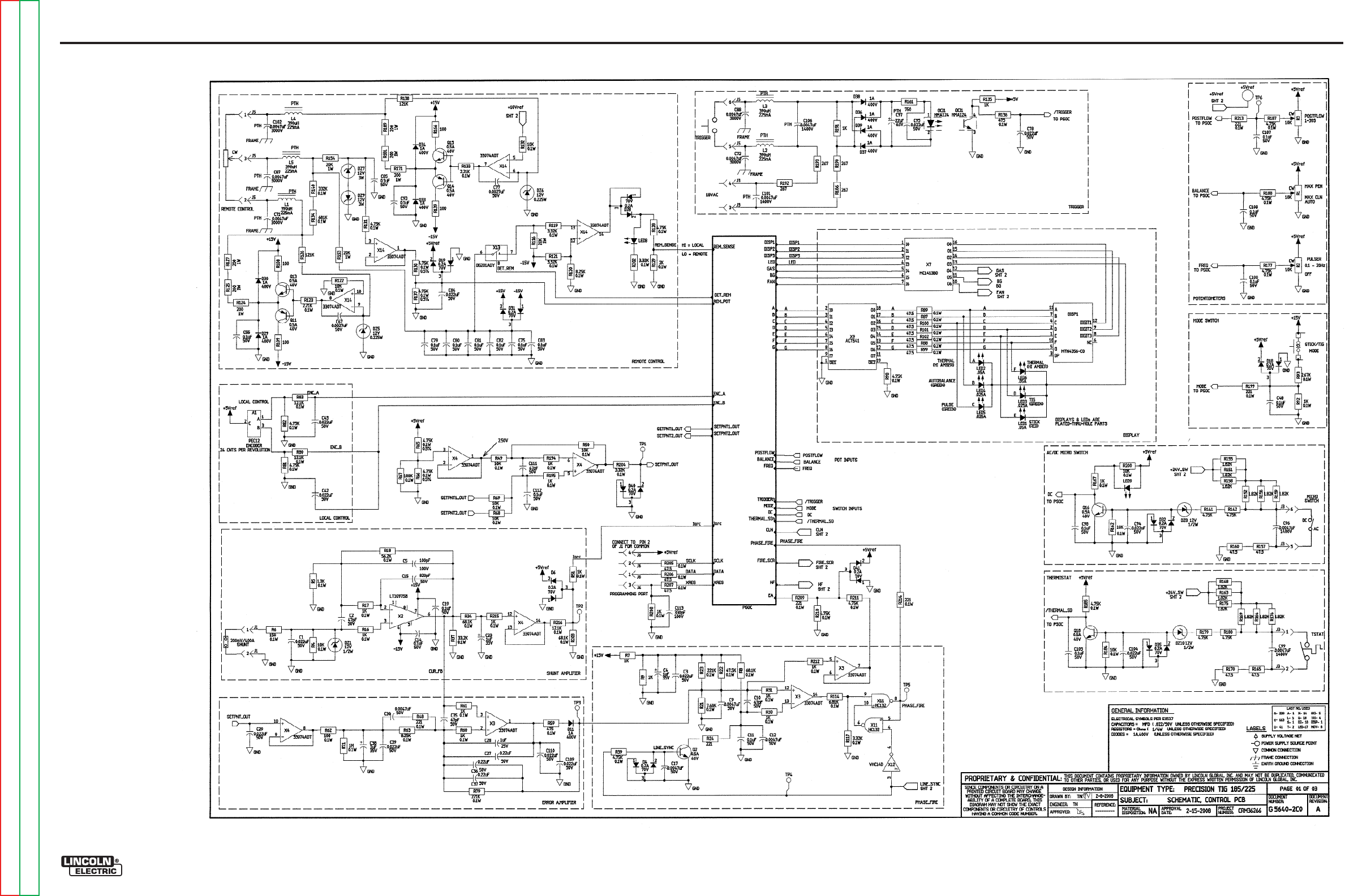
Return to Section TOC Return to Section TOC Return to Section TOC Return to Section TOC
Return to Master TOC Return to Master TOC Return to Master TOC Return to Master TOC
ELECTRICAL DIAGRAMS G-4
PRECISION TIG® 225
SCHEMATIC - CONTROL PC BOARD #1 (G5640)
G-4
NOTE: This diagram is for reference only. It may not be accurate for all machines covered by this manual.

Return to Section TOC Return to Section TOC Return to Section TOC Return to Section TOC
Return to Master TOC Return to Master TOC Return to Master TOC Return to Master TOC
ELECTRICAL DIAGRAMS G-5
PRECISION TIG® 225
SCHEMATIC - CONTROL PC BOARD #2 (G5640)
G-5
NOTE: This diagram is for reference only. It may not be accurate for all machines covered by this manual.
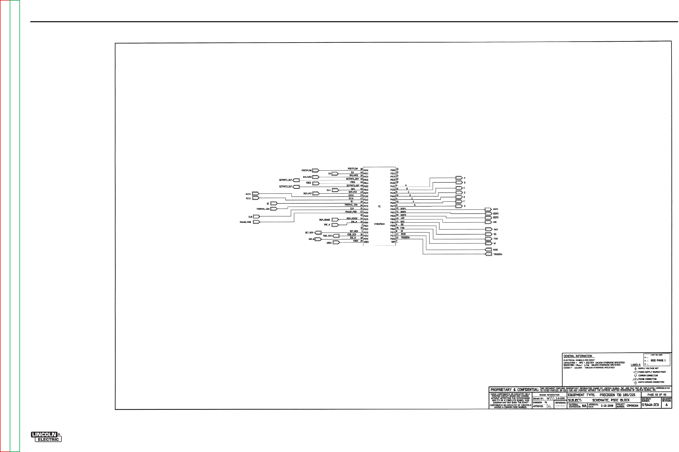
Return to Section TOC Return to Section TOC Return to Section TOC Return to Section TOC
Return to Master TOC Return to Master TOC Return to Master TOC Return to Master TOC
ELECTRICAL DIAGRAMS G-6
PRECISION TIG® 225
SCHEMATIC - CONTROL PC BOARD #3 (G5640)
G-6
NOTE: This diagram is for reference only. It may not be accurate for all machines covered by this manual.
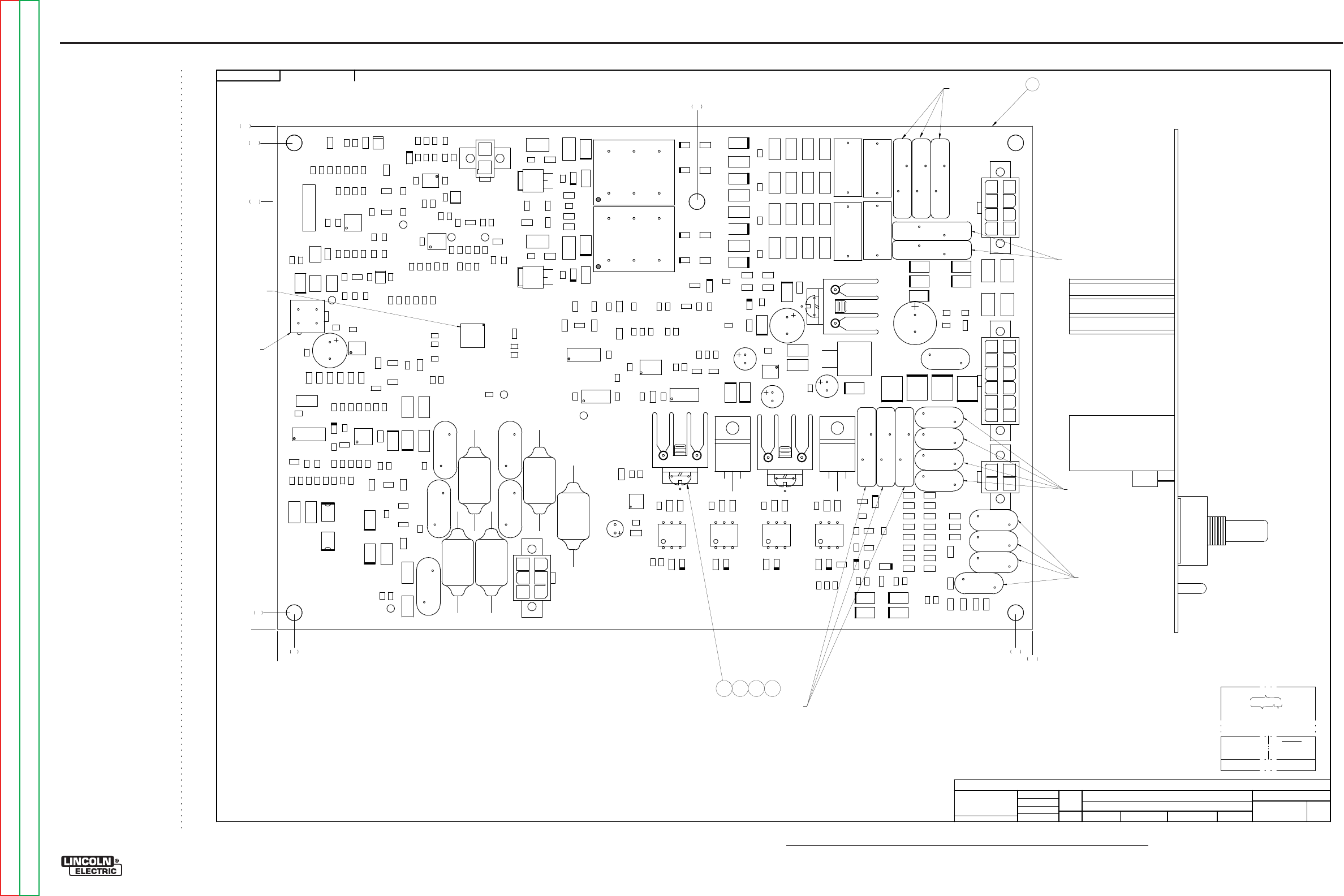
NOTE: Lincoln Electric assumes no responsibility for liablilities resulting from board level troubleshooting. PC Board repairs will invalidate your factory warranty. Individual Printed Circuit Board Components are not available from Lincoln Electric. This information is pro-
vided for reference only. Lincoln Electric discourages board level troubleshooting and repair since it may compromise the quality of the design and may result in danger to the Machine Operator or Technician. Improper PC board repairs could result in damage to the
machine.
ELECTRICAL DIAGRAMS G-7
PRECISION TIG® 225
PC BOARD ASSEMBLY - CONTROL #1 (G5641)
EN-170
SOLIDEDGE
G564
1-
2
PRE
CISI
O
N TIG 185/2
25
CO
NT
R
OL PC BOA
R
D ASSE
M
BLY
1:1.2
5
G4551-
1
DO NO
T
SC
AL
E
T
HIS DR
A
WING
EQ
UIP
M
ENT
TYPE:
SUBJECT:
SCA
L
E:
UF
CRM36266
1
PAGE ___ OF
___
2
E
NGI
N
EE
RI
NG
CO
NT
RO
LLE
D
MA
NU
FA
CT
URE
R:
Y
es
THIS DOCUMENT CONTAINS PROPRIETAR
Y
INFORMATION OWNED B
Y
LINCOLN GLOBA
L, INC.
AND MA
Y
NOT BE DUPLICATED, COMMUNICATED
TO O
THER PARTIES OR US
ED FOR
AN
Y
PURPOS
E WITHOU
T
THE EXPRES
S WRIT
TEN PERMISSION
OF LINCOLN GLOBAL, INC.
PRO
PRIETARY & C
ONFIDENTIAL:
t
MAT
ERI
A
L TO
L
ER
ANC
E ("
"
) TO A
GR
EE
WITH
PU
B
LI
SH
ED
ST
ANDARD
S.
ON A
LL
AN
GL
E
S I
S ± .5 OF
A D
E
GR
EE
ON
3
PLACE
D
E
CIM
ALS
IS
± .
00
2 i
n.
(
±
0.
0
5
mm)
ON 2
PL
AC
E D
ECIM
AL
S I
S ± .02 in. (
±
0.5 mm)
UNLESS OTHERWISE SPECIFIED TOLERANCE:
M
ANUF
ACTURING TO
L
ER
ANC
E
P
ER
E
2056
N
EW
CHAN
GE
D
ET
AIL:
REFER
ENCE:
MA
T
ERI
AL
DIS
PO
SI
T
ION:
AP
PRO
VA
L
DA
T
E:
PROJ
EC
T
NUMBER:
DOCUMEN
T
NUMBER:
DOCUMEN
T
REV
ISI
ON:
IF PR
IN
T
ED
@ A
1
SIZ
E
UNI
T
S:
IN
CH 2/
15
/
2008
d
di
e
tz
Tran
gNg
uye
n
-
DRAWN BY:
ENGINEER:
CL
EV
EL
AND
APPROVED:
CONTROL:
A
G5641-2
Insight
CONT ROL
P
T185
/225
G5 6 4 1- 2
D5
R174
R106
R25
L1
R68
D8
R8
R21
R4
TR
I1
C44
R12 0
C40
C112
L ED15
R87
R171
R51
R6
R16 7
R153
R27
L2
C105
R196
C72
R18 5
C26
R4
7
R1
52
R114
R12 9
R59
Q18
R9
R1
56
R13 4
C92
R78
C1
C109
R206
R125
T2
C76
C93
R147
R113
Q4
R6
4
DZ4
R16
R58
TP3
R72
R96
R
10
C33
R124
C
10
1
MOV 8
D14
C80
C77
R117
C69
D2
8
R215
DZ3
DZ
6
R13 1
R1
55
TR
I3
C34
R12 8
D40
D17
C49
C8
R95
D18
D6
R217
R44
C67
R97
R101
R16 2
R55
R119
C110
R205
R170
R82
R200
C91
LED14
D4
1
C2
R138
TP2
R4
1
LED13
R71
L ED7
C99
C9
4
C111
C57
C25
R81
R161
R52
C65
R13
X7
C14
R75
C61
Q2
R204
R48
R102
C20
D21
Q9
R80
Q14
D20
OC
I5
C104
R216
R127
C87
R12 3
C12
R116
C35
OCI
1
R28
R154
R30
R14 1
R19 4
TP4
C15
R40
R85
R166
C29 C23
C54
R181
R12 2
R109
R1
10
R49
C75
C50
D34
Q13
MOV4
C103
C62
C73
C41
R86
R207
C43
D15
R90
DZ
10
R201
C6
8
R92
R1
76
C88
R220
R1
79
R88
R12
R139
D7
R24
R
105
D24
R18 2
R31
R212
D13
X9
R1
59
R146
R5
MOV 2
D33
R34
TP5
R56
L ED9
Q16
TR
I2
C38
DZ8
C5
1
R3
5
R19 5
R20
R18 3
R7
C24
R115
DZ2
R13 0
C70
LED12
TR
I4
D11
L ED17
D9
R213
X11
R218
R219
R1
69
C97
C30
R1
75
R108
C46
R36
C78
C45
R12 1
R29
R18 7
R1
58
R60
R7
7
C56
L ED16
C74
R208
R43
R214
C71
D37
D27
R38
R63
R18
D38
R100
C17
C3
R199
C42
TP6
R98
C60
R53
DZ1
D23
X12
D1
J 3
R13 6
R210
R172
X13
R1
42
MOV 1
DZ9
R1
80
C59
R14 0
R14
Q1
D36
MOV 6
X3
R186
R19
Q3
D25
R135
C96
R15
R50
R13 3
C7
C10
R4
6
R209
X8
R7
4
D16
R1
68
J 6
Q8
R107
L ED8
R42
C113
C82
R193
C90
R83
X4
C22
OC
I4
C16
LED11
R67
R7
3
C9
5
R22
X1
C27
OC
I3
J1
R173
R144
C36
C21
D3
2
C6
Q
10
C19
C37
R202
D12
R17
R1
57
X2
C83
D39
J 2
C102
R93
C4
8
R1
64
R39
C53
L ED10
R190
R33
R99
R198
L5
R11
Q17
C58
C108
C3
1
Q15
R66
R104
R192
X6
Q11
D19
C18
R143
R112
C86
D4
D30
R203
D3
5
X14
D3
1
C11
C79
C64
C39
R45
R15 1
C32
R94
D3
R111
C4
C66
L3
X
10
R37
C
106
C52
C55
R57
L4
R61
Q6
R1
63
R89
C81
C28
OC
I2
R18 8
C89
R211
R191
C13
R118
R197
C107
R26
R7
6
D22
C85
TP7
D26
DZ7
R17 7
C9
T1
D
10
R79
R18 4
R1
60
MOV 7
R178
MOV5
TP
1
R150
R54
R13 2
R103
X5
R149
D29
R65
C63
R32
Q12
J 4
R148
R84
R13 7
R1
65
MOV 3
C98
DZ
5
C84
R70
R91
R126
C100
R69
J 5
Q5
R145
C5
D2
R189
R23
C47
R62
Q7
COMPONENT SIDE
N.
B.
N.
K.
N.
G.
2 3 4 5
0
.20 8.80
9.00
5.00
0
.20
5.10
5.80
6.00
G5641-2C0
PART NO. IDENTIFI CATION
CODE
MAKE DETAI L
REVISI ON CONTROL
SEE EL EC T RONI C F I LE F OR ADDI TI ONAL I NFOR MATI ON.
SCHEMAT I C REFERENCE: G5640- 2C0
TEST PER E4238- C
COAT WI TH E1844 AND E3668 ( 2 COATS)
4LAYER BOARD BLANK PANEL
MANUFACTUR PER E1911-RoHS
BUY BLANK COMPLETE
(2 BOARDS PER PANEL)
N.
K.
N.
K.
N.
K.
1
N.K.
G-7
Return to Section TOC Return to Section TOC Return to Section TOC Return to Section TOC
Return to Master TOC Return to Master TOC Return to Master TOC Return to Master TOC
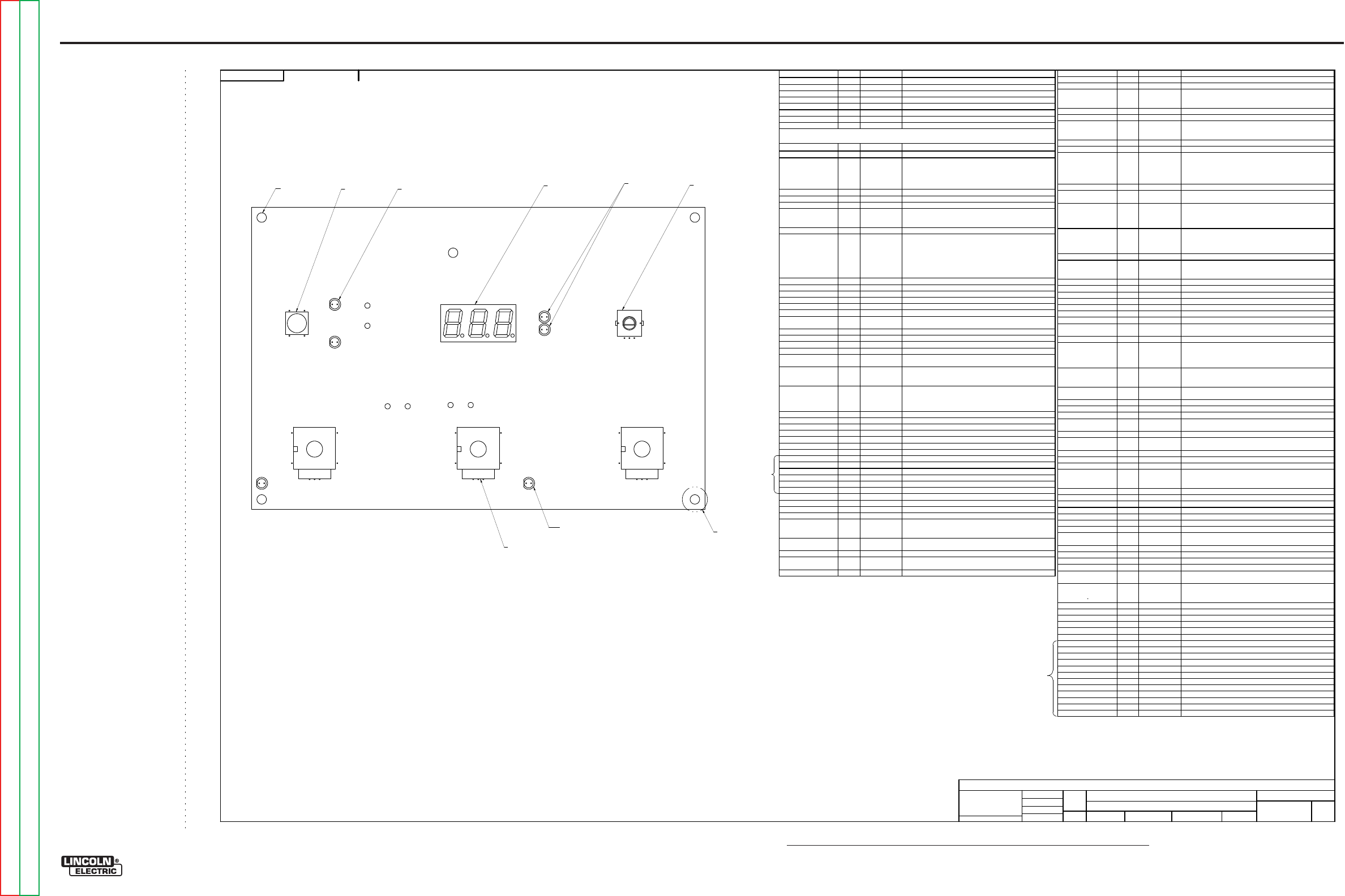
NOTE: Lincoln Electric assumes no responsibility for liablilities resulting from board level troubleshooting. PC Board repairs will invalidate your factory warranty. Individual Printed Circuit Board Components are not available from Lincoln Electric. This information is pro-
vided for reference only. Lincoln Electric discourages board level troubleshooting and repair since it may compromise the quality of the design and may result in danger to the Machine Operator or Technician. Improper PC board repairs could result in damage to the
machine.
ELECTRICAL DIAGRAMS G-8
PRECISION TIG® 225
PC BOARD ASSEMBLY - CONTROL #2 (G5641)
EN-170
SOLIDEDGE
G564
1-
2
PRE
CISI
O
N TIG 185/2
25
CO
NT
R
OL PC BOA
R
D ASSE
M
BLY
1:1.2
5
G4551-
1
DO NO
T
SC
AL
E
T
HIS DR
A
WING
EQ
UIP
M
ENT
TYPE:
SUBJECT:
SCA
L
E:
UF
CRM36266
2
PAGE ___ OF
___
2
E
NGI
N
EE
RI
NG
CO
NT
RO
LLE
D
MA
NU
FA
CT
URE
R:
Y
es
THIS DOCUMENT CONTAINS PROPRIETAR
Y
INFORMATION OWNED B
Y
LINCOLN GLOBA
L, INC.
AND MA
Y
NOT BE DUPLICATED, COMMUNICATED
TO O
THER PARTIES OR US
ED FOR
AN
Y
PURPOS
E WITHOU
T
THE EXPRES
S WRIT
TEN PERMISSION
OF LINCOLN GLOBAL, INC.
PRO
PRIETARY & C
ONFIDENTIAL:
t
MAT
ERI
A
L TO
L
ER
ANC
E ("
"
) TO A
GR
EE
WITH
PU
B
LI
SH
ED
ST
ANDARD
S.
ON A
LL
AN
GL
E
S I
S ± .5 OF
A D
E
GR
EE
ON
3
PLACE
D
E
CIM
ALS
IS
± .
00
2 i
n.
(
±
0.
0
5
mm)
ON 2
PL
AC
E D
ECIM
AL
S I
S ± .02 in. (
±
0.5 mm)
UNLESS OTHERWISE SPECIFIED TOLERANCE:
M
ANUF
ACTURING TO
L
ER
ANC
E
P
ER
E
2056
N
EW
CHAN
GE
D
ET
AIL:
REFER
ENCE:
MA
T
ERI
AL
DIS
PO
SI
T
ION:
AP
PRO
VA
L
DA
T
E:
PROJ
EC
T
NUMBER:
DOCUMEN
T
NUMBER:
DOCUMEN
T
REV
ISI
ON:
IF PR
IN
T
ED
@ A
1
SIZ
E
UNI
T
S:
IN
CH 2/
15
/
2008
d
di
e
tz
Tran
gNg
uye
n
-
DRAWN BY:
ENGINEER:
CL
EV
EL
AND
APPROVED:
CONTROL:
A
G5641-2
Insight
NOTES:
N.A.
THIS DEVICE IS SUBJECT TO DAMAGE BY STATIC ELECTRICITY, SEE E2454 BEFORE
HANDLI NG.
N.B.
PROGRAM X1 WITH ITEM 6
.
N.C.
KEEP FREE OF ENCAPSULATION MATERIAL.
N.D.
SEAL COMPONENT BY APPLYING ITEM
7
AS SHOWN SO THAT ENCAPSULATION MATERIAL
DOES NOT GE
TINSIDE COMPONENT.
N.E.
KEEP FREE OF ENCAPSULATION MATERIAL (.50 DIA. MIN.) ON BOTH SIDES OF BOARD.
N.F.
KEEP MOUNTING HOLES FREE OF ENCAPSULATION MATERIAL (5 PLACES).
N.G.
COVER MOLEX WITH TAPE.
N.H.
HAND TIGHT MOUNTING WASHER AND MOUNTING NUT TO POTENT
IOMETER BUSHING.
N.J.
WHEN ASSEMBLING DISPLAY, SPACE DISPLAY OFF THE BOARD .125+/
-
.010 MEASURED
FROM BOTTOM OF DISPLAY TO PC BOARD SURFACE.
N.K.
SQUEEZE COMPONENTS TOGETHER BEFORE ENCAPSULATION.
N.L.
SEAL COMPONENT BASE WITH ITEM 8.
N.
A.
N.C.
CAPA
CI
TO
R
S
=
MF
D
/
V
OL
TS
RE
SI
S
TO
R
S
=
OHMS
OCI1
1
S15000-34SMT
IC,SMD,OPTOCOUPLER,HMA124
OCI2, OCI3, OCI4, OCI5 4
S15000-16
OPTOCOUPLER,TRIAC,DRIVER,ZVC,3083
Q1, Q6 2
S25051-11SMT
TRANSISTOR,SMD,NMF,DPAK,TO-252,48A,100V(SS)
Q2, Q3, Q5, Q7, Q9, Q10,
Q12, Q13, Q15, Q16,
Q17, Q18
12
S25050-1SMT
TRANSISTOR,SMD,NPN,0.5A,40V,SOT-23,MMBT4401LT1
Q4, Q8, Q11, Q14 4
S25050-2SMT
TRANSISTOR,SMD,PNP,SOT23,0.5A, 40V,MMBT4403LT1
R1, R2, R3 3
T10812-116
POT,SINGLE-TURN,0.25W,10K,10%
R4, R49, R50, R68, R69,
R72, R107, R122, R132,
R162, R184, R200
12
S25000-1002SMT
RESISTOR,SMD,METAL FILM,1/10W,10.0K,1%,S0805
R5
1
S25000-1301SMT
RESISTOR,SMD,METAL FILM,1/10W,1.30K,1%,S0805
R6
1
S25000-1500SMT
RESISTOR,SMD,METAL FILM,1/10W ,150OHMS,1%,S0805
R7, R9, R111, R112,
R113, R135, R143, R145,
R147, R149, R172, R173,
R174, R178, R191, R196,
R197, R198
18
S25001-1001SMT
RESISTOR,SMD,1K,1/4W,1206,1%,TR
R8, R34, R203 3
S25000-6812SMT
RESISTOR,SMD,METAL FILM,1/10W,68.1K,1%,S0805
R10, R11, R52, R53, R90,
R91, R103, R104 8
S25004-1R00SMT
RESISTOR,SMD,1W,1.00OHMS,1%
R12, R13, R14, R15, R26,
R27, R28, R29, R42, R43,
R44, R45, R55, R56, R57,
R58
16
S25003-1210SMT
RESISTOR,SMD,1W,121OHMS,1%
R16, R17, R30, R31, R32,
R51, R60, R61, R92,
R167, R194, R195, R208,
R212, R215
15
S25000-1001SMT
RESISTOR,SMD,METAL FILM,1/10W,1.00K,1%,S0805
R18
1
S25000-5622SMT
RESISTOR,SMD,METAL FILM,1/10W,56.2K,1%,S0805
R19, R64, R157, R160,
R165, R170, R217, R218,
R219, R220
10
S25001-47R5SMT
RESISTOR,SMD,47.5OHMS,1/4W,1206,1%,TR
R20, R36, R41, R54 4
S25003-15R0SMT
RESISTOR,SMD,1W,15.0OHMS,1%
R21
1
S25000-7681SMT
RESISTOR,SMD,METAL FILM,1/10W,7.68K,1%,S0805
R22
1
S25000-4752SMT
RESISTOR,SMD,METAL FILM,1/10W,47.5K,1%,S0805
R23, R79 2
S25000-2213SMT
RESISTOR,SMD,METAL FILM,1/10W,221K,1%,S0805
R24
1
S25001-2210SMT
RESISTOR,SMD,221OHMS,1/4W,1206,1%,TR
R25, R75 2
S25006-10R0SMT
RESISTOR,SMD,METAL FILM,1/2W,10OHMS,1%,S2010
R33, R38 2
S25008-1002SMT
RESISTOR,SMD,PREC,MF,1/10W,10.0K,0.5%,S0805
R35, R84, R108, R109,
R139, R166 6
S25001-1000SMT
RESISTOR,SMD,100OHMS,1/4W,1206,1%,TR
R37, R85, R106 3
S25000-3322SMT
RESISTOR,SMD,METAL FILM,1/10W,33.2K,1%,S0805
R39, R81, R82, R98,
R128, R131, R177, R182,
R185, R187, R188, R210,
R211
13
S25000-4751SMT
RESISTOR,SMD,METAL FILM,1/10W,4.75K,1%,S0805
R40, R46, R47, R73, R74,
R76, R77, R86, R96, R97,
R141, R142, R179, R180
14
S25001-4751SMT
RESISTOR,SMD,4.75K,1/4W,1206,1%,TR
R48, R199, R209, R213,
R214
5
S25000-2210SMT
RESISTOR,SMD,METAL FILM,1/10W ,221OHMS,1%,S0805
R59, R136 2
S25000-4750SMT
RESISTOR,SMD,METAL FILM,1/10W ,475OHMS,1%,S0805
R62
1
S25000-1000SMT
RESISTOR,SMD,METAL FILM,1/10W ,100OHMS,1%,S0805
R63, R120 2
S25000-8251SMT
RESISTOR,SMD,METAL FILM,1/10W,8.25K,1%,S0805
R65, R66, R94, R95,
R130, R137 6
S25008-4751SMT
RESISTOR,SMD,PREC,MF,1/10W,4.75K,0.5%,S0805
R67
1
S25000-1003SMT
RESISTOR,SMD,METAL FILM,1/10W,100K,1%,S0805
R70, R117, R119, R121,
R202, R204 6
S25000-3321SMT
RESISTOR,SMD,METAL FILM,1/10W,3.32K,1%,S0805
R71
1
S25000-1004SMT
RESISTOR,SMD,METAL FILM,1/10W,1.00M,1%,S0805
R78
1
S25001-1002SMT
RESISTOR,SMD,10K,1/4W ,1206,1%,TR
R80, R83, R216 3
S25000-1212SMT
RESISTOR,SMD,METAL FILM,1/10W,12.1K,1%,S0805
R87, R88, R89, R99,
R100, R101, R102, R205,
R206, R207
10
S25000-47R5SMT
RESISTOR,SMD,METAL FILM,1/10W ,47.5OHMS,1%,S0805
R93
1
S25000-2671SMT
RESISTOR,SMD,METAL FILM,1/10W,2.67K,1%,S0805
R105, R110 2
S25003-47R5SMT
RESISTOR,SMD,1W,47.5OHMS,1%
R114
1
S25000-6811SMT
RESISTOR,SMD,METAL FILM,1/10W,6.81K,1%,S0805
R115
1
S25000-2212SMT
RESISTOR,SMD,METAL FILM,1/10W,22.1K,1%,S0805
R116, R153, R154 3
S25003-2002SMT
RESISTOR,SMD,1W,20.0K,1%
R118
1
S25001-4752SMT
RESISTOR,SMD,47.5K,1/4W,1206,1%,TR
R123, R133 2
S25000-2211SMT
RESISTOR,SMD,METAL FILM,1/10W,2.21K,1%,S0805
R124, R125, R127, R171,
R181, R189 6
S25003-2000SMT
RESISTOR,SMD,1W,200OHMS,1%
R126, R138 2
S25001-1213SMT
RESISTOR,SMD,121K,1/4W,1206,1%,TR
R129
1
S25000-2001SMT
RESISTOR,SMD,METAL FILM,1/10W,2.00K,1%,S0805
R134
1
S25000-6813SMT
RESISTOR,SMD,METAL FILM,1/10W,681K,1%,S0805
R140
1
S25000-3323SMT
RESISTOR,SMD,METAL FILM,1/10W,332K,1%,S0805
R144, R146, R148, R150,
R186, R190, R192, R193 8
S25001-2670SMT
RESISTOR,SMD,267OHMS,1/4W,1206,1%,TR
R151, R152, R155, R156,
R158, R159, R163, R164,
R168, R169, R175, R176
12
S25001-1821SMT
RESISTOR,SMD,1.82K,1/4W,1206,1%,TR
R161
1
S25001-7500SMT
RESISTOR,SMD,750OHMS,1/4W,1206,1%,TR
R183
1
S25000-1502SMT
RESISTOR,SMD,METAL FILM,1/10W,15.0K,1%,S0805
R201
1
S25001-2211SMT
RESISTOR,SMD,2.21K,1/4W,1206,1%,TR
S1
1
T13381-16
SWITCH,PUSHBUTTON,SPST
T1, T2 2
T12737-2
TRANSFORMER,PULSE,3-WINDING,1:1:1
TRI1, TRI2, TRI3, TRI4 4
S15161-27
TRIAC,TO220,8A,800V
X1
1
S25073-12SMT
IC,SMD,CMOS,PSOC,8-BIT,CY8C27643,TFN49(SS)
X2
1
S15128-27SMT
IC,OP-AMP,SINGLE,PRECISION,LT1097S8
X3, X4, X14 3
S15128-28SMT
IC,OP-AMP,SMT,QUAD,HIGH-PERF,33074ADT
X5
1
S15128-6
IC,VOLT REG,FIXED,3-T,(+),1A,15V,TO220
X6
1
S15128-10SMT
IC,SMD,VOLTAGE REF,A DJ, PRECISION,431I,SOIC-8
X7
1
M15102-4SMT
IC,SMD,ARRAY,DRIVER,PERIPHERAL,NPN,DARLINGTON
X8
1
S15128-5SMT
IC,VOLT REG,SMD,FIXED,3-T,(+),1A,5V
X9
1
S25072-2SMT
IC,SMD,ACT,BUFFER,OCTAL,3-STATE,TSSOP-20(SS)
X10
1
S15018-21SMT
IC,SMD,CMOS,DRIVER,MOSFET,4451, SOIC-8(SS)
X11
1
S17900-24SMT
IC,SMD,CMOS,GATE,NAND,2-INPUT,QUAD,SCHM(SS)
X12
1
S25065-3SMT
IC,SMD,CMOS,INVERTER,SCHMITT,HEX,VHC14(SS)
X13
1
S15018-11SMT
IC,SMD,CMOS,SWITCH,ANALOG,QUAD,201(SS)
ITEM (USED WITH)*`
QTY
PART NUMBER
DESCRIPTION
11
G5641-C
PC BOARD BLANK
2(TRI1, TRI3, X5)* 3
CF000003
6-32 X .375 ROUND HEAD MACHINE SCREW
3(TRI1, TRI3, X5)* 3
E106A-13
# 6 LOCK WASHER
4(TRI1, TRI3, X5)* AS REQ
E1868
THERMO JOINT COMPOUND
5(TRI1, TRI3, X5)* 3
S18104-3
HEAT SINK,ALUMINUM,EXTRUDED,FOR 1 TO-220
61
S26585-4
PSOC SOFTWARE
7AS REQ
E2861
SEALANT
8AS REQ
E2519-1
SEALANT
REFERENCES
QTY
PART NUMBER
DESCRIPTION
A1
1
M17789-4
ENCODER,INCREMENTAL,2-BIT,PEC12
C1, C3, C29, C39, C41,
C42, C43, C58, C60, C78,
C84, C89, C90, C91, C92,
C94, C95, C103, C104,
C109, C110
21
S25020-2SMT
CAPACITOR,SMD,CERAMIC,0.022MF,50V,10%,X7R,S0805
C2, C10, C35, C111 4
S25020-9SMT
CAPACITOR,SMD,CERAMIC,47pF,50V,5%,COG,S0805
C4, C23, C38 3
S25024-2SMT
CAPACITOR,SMD,TANTALUM,1.0MF,35V,10%,S3528
C5, C20, C45 3
S25020-12SMT
CAPACITOR,SMD,CERAMIC,100pF,100V,5%,COG,S0805
C6, C7, C9, C12, C17,
C18, C24, C30, C31, C32,
C34, C44, C53, C59
14
S25020-10SMT
CAPACITOR,SMD,CERAMIC,4700pF,50V,10%,XR7,S0805
C8, C13, C25, C26 4
S20500-17
CAPACITOR,PPMF,0.1MF,630V,5%,BOX
C11, C14, C19, C21, C22,
C33, C48, C50, C51, C52,
C55, C56, C62, C64, C66,
C68, C74, C75, C76, C79,
C80, C81, C82, C83, C85,
C93, C98, C100, C105,
C107, C108, C112
32
S25020-3SMT
CAPACITOR,SMD,CERAMIC,0.1MF,50V,10%,X7R,S0805
C15, C63 2
S25020-4SMT
CAPACITOR,SMD,CERAMIC,820pF,50V,5%,COG,S0805
C16, C40, C113 3
S25020-14SMT
CAPACITOR,SMD,CERAMIC,330pF,100V,5%,COG,S0805
C27, C36, C37 3
S25020-7SMT
CAPACITOR,SMD,CERAMIC,0.22MF,50V,20%,X7R,S1812
C28
1
S25020-24SMT
CAPACITOR,SMD,CERAMIC,1.0MF,25V,10% ,X7R,S1206
C46, C49 2
S13490-199
CAPACITOR,ALEL,220,25V,20%,LOW -ESR
C47
1
S13490-179
CAPACITOR,ALEL,1000,35V,20%
C54, C69, C70, C73, C86,
C96, C99, C101, C106 9
T11577-52K
CAPACITOR,CD,.0047/.005,1400V,20%
C57, C61, C65 3
S13490-197
CAPACITOR,ALEL,82,35V,20%,LOW -ESR
C67, C77 2
S25020-5SMT
CAPACITOR,SMD,CERAMIC,2700pF,50V,5%,X7R,S0805
C71, C72, C87, C88, C102 5
T11577-58K
CAPACITOR,CD,.0047,3000V,20%
C97
1
S13490-181
CAPACITOR,ALEL,22,63V,20%
D1, D2, D3, D5, D7, D8,
D21, D22 8
S25040-1SMT
DIODE,SMD,1A,400V,FAST RECOVERY,DO-214BA
D4, D6, D16, D18, D19,
D20, D28, D31, D32, D35,
D40, D41
12
S25040-5SMT
DIODE,SMD,DUAL,0.200A,70V,UFR
D9, D10, D11, D12, D13,
D14, D15, D17, D23, D29,
D30, D33, D34, D36, D37,
D38, D39
17
S25040-2SMT
DIODE,SMD,1A,400V,DO-214BA/AC
D24, D25, D26, D27 4
S25040-10SMT
DIODE,SMD,3A,400V,D0-214AB
DISP1
1
S17395-11
LED,DISPLAY,7-SEGMENT,CC,3-DIGIT
DZ1, DZ8, DZ10 3
S25046-4SMT
ZENER DIODE,SMD,0.5W,12V,5%,SOD-123
DZ2, DZ3 2
S25046-3SMT
ZENER DIODE,SMD,0.5W,18V, 5%,SOD123
DZ4
1
S25046-1SMT
ZENER DIODE,SMD,0.5W,5.1V, 5%,SOD123
DZ5, DZ6 2
S25045-1SMT
ZENER DIODE,SMD,225mW,12V,5%,SOT-23
DZ7, DZ9 2
S25044-3SMT
ZENER DIODE,SMD,3W,12V,5%, SMB
J1
1
S24020-2G
CONNECTOR,MOLEX,MINI,PCB,2-PIN,GOLD
J2
1
S24020-8
CONNECTOR,MOLEX,MINI,PCB,8-PIN,TIN
J3
1
S24020-12
CONNECTOR,MOLEX,MINI,PCB,12-PIN,TIN
J4
1
S24020-4
CONNECTOR,MOLEX,MINI,PCB,4-PIN,TIN
J5
1
S24020-6
CONNECTOR,MOLEX,MINI,PCB,6-PIN,TIN
J6
1
S18248-4
CONNECTOR,MOLEX,MINI,PCB,4-PIN
L1, L2, L3, L4, L5 5
T12218-9
CHOKE,RF,390UH,5%, 225MA,CONFORMAL
LED1
1
T13657-2
LED,T-1,3/4,RED,HLMP-3003
LED2, LED6 2
T13657-14
LED,T-1,3/4,AMBER,HIGH-INTENSITY
LED3, LED4, LED5 3
T13657-3
LED,T-1,3/4,GREEN,HLMP-3502
LED7, LED8, LED9,
LED10, LED15, LED16,
LED17
7
S25080-2SMT
LED,SMD,GREEN,CLEAR,S1206
LED11, LED12, LED13,
LED14
4
S25080-1SMT
LED,SMD,RED,CLEAR,S1206
MOV1
1
T13640-16
MOV,150VRMS,80J,20MM
MOV2, MOV3, MOV4,
MOV5
4
T13640-25
MOV,130VRMS,90J,20MM
MOV6, MOV7, MOV8 3
T13640-18
MOV,320VRMS,150J,20MM
REFER TO ELECTRONIC COMPONENT DATABASE FOR SPECIFICATIONS ON ITEMS LISTED BELOW
ALL COMPONENTS AND MATERIALS USED
I
NTHIS
ASSEMBLY ARE TO BE RoHS COMPLIANT PER E4253
N
.L.
N.C.
N.
C.,
N.D. N.C.
N.F.
N.
E.
N.
C.,
N.
D.,
N.
H. (3
PL
ACE
S)
N.C.
N.
C.,
N.J.
XX XX X
XXXX X
X
X
X
X
X
X
X
X
X
X
X
X
X
X
X
X
XX
XXXXXX
XXXXX
XXXXXX
XXXXX
X
X
X
X
X
X
X
X
X
X
XXXXXX
X
X
X
X
X
X
X
X
XXXXX X
X
XXX
XXX
X
X
X
X
X
X
X
XA1
L
ED
6
R3
S1
L
ED
5
L
ED
1
R2
L
ED
2
DI
SP
1
L
ED
4
L
ED
3
R1
OPPOSITE COMPONENT SIDE
G-8
Return to Section TOC Return to Section TOC Return to Section TOC Return to Section TOC
Return to Master TOC Return to Master TOC Return to Master TOC Return to Master TOC
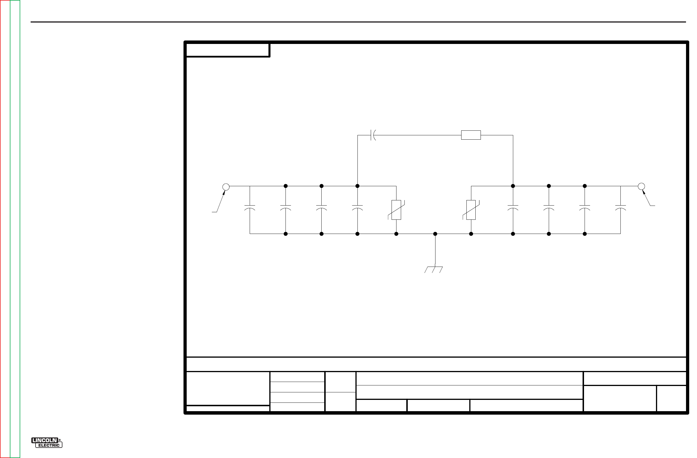
Return to Section TOC Return to Section TOC Return to Section TOC Return to Section TOC
Return to Master TOC Return to Master TOC Return to Master TOC Return to Master TOC
ELECTRICAL DIAGRAMS G-9
PRECISION TIG® 225
SCHEMATIC - BYPASS PRINTED CIRCUIT BOARD (S22530)
EN-164
SOLIDEDGE
S22530-1B0
BYPASS/STABILIZER BOARD
SCHEMATIC
NONE
S22530
FEI
U
NLESS
OT
HERWI
SE SPE
C
IF
IED
T
OLE
RANCE
MAN
UFA
CT
URING
TOLE
RA
N
CE PER E2056
ON
2
PLACE
DEC
I
MALS
IS
±
.0
2
ON
3
PLA
CE DE
CI
MA
LS
IS
±.002
ON
ALL
AN
GLES
IS
±
.5
OF A
DEG
REE
WITH
PUBL
ISHED
STANDAR
DS.
MATERIAL T
OLE
RAN
CE
(" ")
TO
AG
REE
t
DO N
OT
S
CA
L
E TH
IS
D
RA
WING
D
RAW
N
BY:
DESIG
NIN
FO
R
MA
T
IO
N
ENGI
NEER
:
APP
R
OVE
D:
REFERENCE:
EQ
UIPMENT TYPE:
SUBJECT:
SC
ALE
:
S22530-1B0
MATERIAL
DISPOS
IT
ION:
APPROVAL
DATE:
PROJECT
NUMBER:
NA CRM34563
1
PAGE _
_
_ OF __
_
1
EN
GI
NEE
RIN
G
CO
NTR
OL
L
ED
M
AN
UF
ACTU
RE
R: No
NEW
DOC
UM
E
NT
N
UM
BE
R:
DOCUMENT
REVISION:
THIS
DO
CU
ME
NT CO
NTAINS
PROPRI
ET
ARY
IN
FO
R
MATION O
W
NE
D BY
L
IN
COL
N GLO
B
AL
,
IN
C. AN
D
MAY NOT
BE
D
UPLICAT
ED, CO
MMU
NI
CATED
TO
O
THER P
ARTI
ES
OR USED FOR ANY
PU
RPOS
EWI
THO
UT THE
EX
PRE
SS W
RITT
EN
P
ER
MISS
ION OF L
IN
COL
N GLO
B
AL
,
INC.
PROPRIETARY & CONFIDENTIAL:
A
08/26/2002
C
HA
N
GE
DETAI
L:
S
TRP
GND CONNECTION MADE THROUGH SOLDER PAD
CONNECTION MADE THROUGH
ARC
STA
B
IL
IZER
Gra
p
hic
Gra
p
hic
A
RC
ST
A
BILIZER
CA
P
AC
ITOR
RES
I
STOR
AND SCREW TO STEEL STANDO
FF
ON MACHINE
CONNECTION MADE THROUGH
HOLE WITH
SOLDER
P
AD
HOLE WITH
SOLDER
P
AD
C1
.05
600
V
C2
.05
600
V
C3
.05
600
V
C4
.05
600
V
TP1
32
0V
160J
GND
TP2
32
0V
160J
C5
.05
600
V
C6
.05
600
V
C7
.05
600
V
C8
.05
600
V
C9
15
250V
R1
10
5W
G-9
NOTE: This diagram is for reference only. It may not be accurate for all machines covered by this manual.
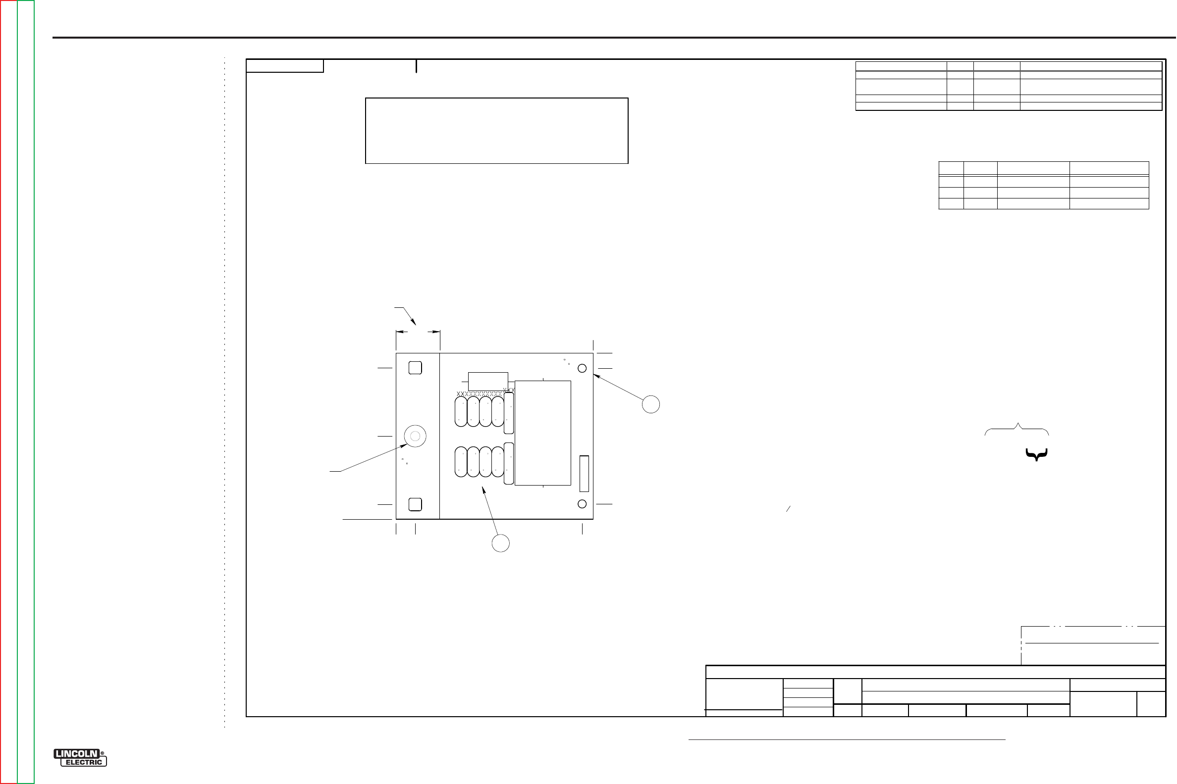
NOTE: Lincoln Electric assumes no responsibility for liablilities resulting from board level troubleshooting. PC Board repairs will invalidate your factory warranty. Individual Printed Circuit Board Components are not available from Lincoln Electric. This information is pro-
vided for reference only. Lincoln Electric discourages board level troubleshooting and repair since it may compromise the quality of the design and may result in danger to the Machine Operator or Technician. Improper PC board repairs could result in damage to the
machine.
ELECTRICAL DIAGRAMS G-10
PRECISION TIG® 225
PC BOARD ASSEMBLY - BYPASS (L10121)
EN-168
SOLIDEDGE
L10121-3
SW
TI
G
175
& 275
BYPASS/STABILIZER P.C. BOARD ASSEMBLY
1:1
L1012
1-1
DO N
OT S
CA
LE
TH
IS
D
RAW
ING
EQU
IP
ME
NT
TYPE
:
SU
BJ
EC
T:
UF
CRM34
432
1
PA
GE
___
OF
___
1
ENGINE
ERING CONTROL
L
ED
MANUFACTURER:
No
T
HIS
DOC
UME
N
T C
ON
TAINS P
R
OP
RIETA
RY IN
FO
RMATIO
N
OW
NE
D BY L
IN
C
OLN
GLOBAL, IN
C. A
N
D MAY NOT BE
D
UPLI
CA
TE
D,
C
OMMU
NI
CA
TE
D
TO OT
HE
R PA
R
TIES O
R
USE
D
FO
R A
NY P
U
RP
OSE WIT
HOU
T THE E
X
PRESS
W
RITTE
N PE
RMISSIO
N
OF LIN
C
OLN
GLOBAL, IN
C.
PROPRI
ETA
RY & CONFIDE
NTIAL:
REVISED P.C.
B
OARD B
L
ANK
INFORMAT
ION
t
MAT
ERIAL TOLERANCE (
"
")
TO A
G
REE
WITH PUBLISHED
STANDARDS.
O
N ALL AN
GLES IS
±
.5
OF A
DEG
REE
ON
3
P
LA
C
E
DECIM
ALS
IS
±
.0
02
i
n.
(
±
0.05
mm)
O
N 2
PLACE DEC
IMALS IS
±
.02
in
. (
±
0.5
mm)
U
NLESS
OTHERW
ISE
SPE
C
IF
IE
D
TOLERA
N
CE
:
MANUFACTURIN
G
TOLERANCE PER
E2056
C
HA
N
GE DE
T
AIL:
REFE
RE
N
CE:
SCA
LE:
MATE
RIAL
DISPO
SITION:
APP
ROV
AL
DAT
E:
PRO
JE
CT
NU
MBE
R:
DOCUMENT
N
UMBER:
DOCUMENT
REVIS
I
ON:
U
NITS:
IF
PRIN
TED
@
A2
S
IZE
IN
CH
9-7-
2007
f
ivory
-
-
DR
A
WN
BY:
E
NG
IN
EE
R:
CLEVELAND
APP
RO
VE
D:
CO
NT
ROL:
C
L10121-3
Insigh
t
C
AP
ACI
TORS
=MFD
/V
OLTS
INDU
CTA
NC
E
=HENR
YS
1
P.
C
. B
OARD
BLA
NK1
I
TEM
REQ'D
PA
RT N
O.
IDE
NTIFI
C
ATION
3
.16
OZ
E2861
SE
ALA
NT
SE
E BL
AN
K I
NF
O.
M
AK
E P
ER
E191
1-
ROHS
TES
T
PE
R
E355
3-
B
L101
21-3
D0
MANUFA
CTU
RED
AS:
IDE
NTIFI
C
ATION
CODE
N.C
.
SQ
U
EE
ZE TOGETHE
R
I
TEM
S
C1-C
4,
TP1
A
ND
C5-C
9,
TP2
BEF
OR
E APPLYI
N
G SEAL
A
NT.
N.D
.
APPLY SEALA
NT AS S
HO
WN
.
BOT
TOM O
F BO
ARD.
N
OTES:
ENC
AP
SU
LATE
WI
TH E1844,
2
CO
ATS.
N
.F. KEEP
THIS A
R
EA F
R
EE O
F E
NC
APS
U
LAT
IO
N
,
TOP
A
ND
N
.G.
TIN
ALL E
X
POS
ED C
OPP
ER WI
TH SOL
DER
IN T
H
IS A
R
EA,
BOT
H
SI
D
ES O
F BO
ARD.
WI
THI
N 0.5" 0 (B
OTH SI
D
ES
).
N.H
.
N
O I
CIC
LES O
R
SOL
DER
BLOBS A
R
E PE
RMIT
TED
SCHEM
ATIC
REFERENC
E: S
22530
-3
D0
FOR
P
A
RTS
ORDER
S
ONLY:
INCLUD
E S2
2772P
RI
NT
3
1
(.3
38
)
(3.
462
)
N.C
.,
N.D.
0
3.80
±
.04
(3.
450
)
(.3
50
)
(1.
900
)
4.50
±
.04
(.4
38
)
(4.
250
)
0
1.00
XXX
XXXXXXXXXXX
XXXXXXXXXXX
XXX
XXXXXXXXXXX XXX
N
.F.
,
N
.G.
N.H.
XXXXXXXXXXXXX
XXXXXXXXXXXXX
XXXXXXXXXXXXXXXXXXXXXXXXXXXXX
XXXXXXXXXXXXXXXXXXXXXXXXXXXXX
TP1 TP2
R1
C9
C1
C2
C3
C4
C5
C6
C7
C8
L10121-3 BYPASS/STABILIZER
SE
E EL
E
CTR
ONIC
FI
LE
FOR
A
DDIT
IO
N
AL I
NFORM
ATION
P.C
.
BOARD
BL
ANK
I
NFORM
ATI
ON
BU
Y
COM
PLETE AS
L10121
-D
(2
LA
YE
R
B
OARD
PE
R
E328
1
WI
TH LEA
D
F
R
EE
H
ASL
SURFAC
E
FI
N
IS
H
).
M
AK
ES 1
2 B
OARD
S P
ER
PA
N
EL.
A
LL
C
OMP
ON
E
NT
S A
ND
MATE
RI
ALS
U
SE
D IN
TH
IS
ASSEM
BL
YARE TO
B
E
R
oH
S
C
OMPLIA
NT
PE
R
E4253.
REFERENCES
QTY
PART NUMBER DESCRIPTION
C1, C2, C3, C4, C5, C6, C7, C8 8
T11577-58K
CAPACITOR,CD,.0047,3000V,20%
C9
1
S13490-155
CAPACITOR,POLYPROPYLENE METALLIZED
FILM,PPMF,15MF,250VAC,10%
R1
1
T14648-25
RESISTOR,WW,5W,10,5%,SQ
TP1, TP 2 2
T13640-18
MOV,320VRMS,150J,20MM
G-10
Return to Section TOC Return to Section TOC Return to Section TOC Return to Section TOC
Return to Master TOC Return to Master TOC Return to Master TOC Return to Master TOC
