Lincoln Electric Prince Im818 Users Manual
IM818 to the manual 4f702483-2e73-42fc-9253-f7d9acb0d409
2015-02-09
: Lincoln-Electric Lincoln-Electric-Prince-Im818-Users-Manual-574139 lincoln-electric-prince-im818-users-manual-574139 lincoln-electric pdf
Open the PDF directly: View PDF ![]() .
.
Page Count: 45
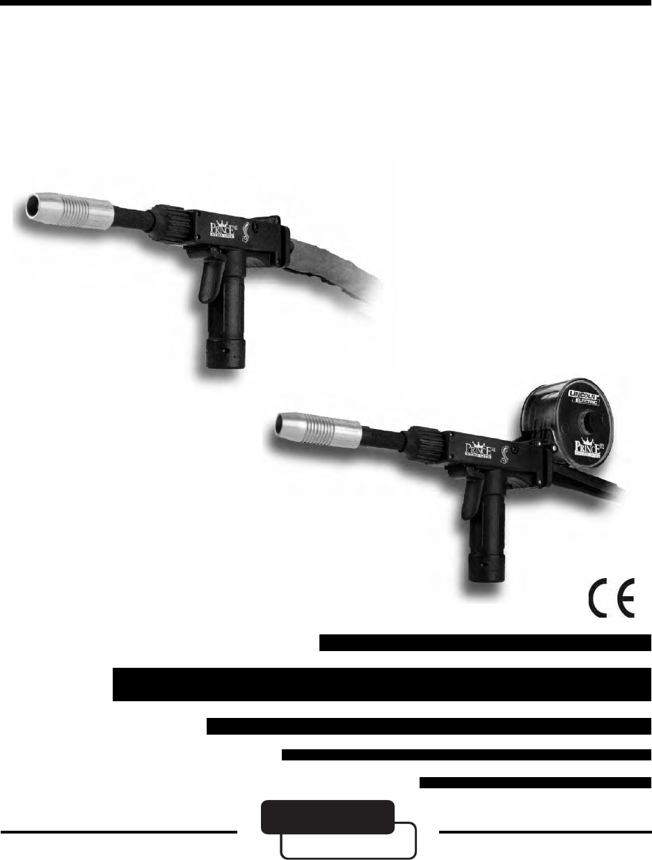
Prince
®
XL/Spool Gun
IM818
MK 091-0531
April 2003
Rev A
OPERATOR'S MANUAL
GMAW
Push-Pull Gun
Safety Depends on You
Lincoln arc welding equipment is
designed and built with safety
in mind. However, your overall
safety can be increased by proper
installation...and thoughful opera-
tion on your part. DO NOT
INSTALL, OPERATE OR REPAIR
THIS EQUIPMENT WITHOUT
READING THIS MANUAL AND
THE SAFETY PRECAUTIONS
CONTAINED THROUGHOUT.
And, most importantly, think before
you act and be careful.
OPERATOR’S MANUAL
Model #350 (factory model)
For use with Cabinet K2259-1
Sales and Service through Subsidiaries and Distributors Worldwide
Cleveland, Ohio 44117-1199 U.S.A. TEL: 216.481.8100 FAX: 216.486.1751 WEB SITE: www.lincolnelectric.com
World’s Leader in Welding and Cutting Prodcuts
LINCOLN
ELECTRIC
®
Copyright © 2003 Lincoln Global Inc.
RETURN TO MAIN MENU
Prince® XL - Owner's Manual - Page i
Prince® XL - Owner's Manual - Page ii
Prince® XL - Owner's Manual - Page iii
Prince® XL - Owner's Manual - Page iv

Prince® XL - Owner's Manual - Page v

Prince® XL - Owner's Manual - Page vi
Thank You For selecting a quality product. We want you to take
pride in operating this product...as much pride as we
have in bringing the product to you!
When this equipment is shipped, title passes to the purchaser upon receipt by the
carrier. Consequently, claims for material damaged in shipment must be made by the
purchaser against the transportation company at the time the shipment is received.
Please record your equipment identification information below for future reference. This
information can be found on your machine nameplate.
Model Name & Number _____________________
Code & Serial Number _____________________
Date of Purchase _____________________
Whenever you request replacements parts for, or information on this equipment always
supply the information you have recorded above.
Please Examine Carton and Equipment For Damage Immediately
Read this Owner’s Manual completely before attempting to use this equipment. Save this manual
and keep it handy for quick reference. Pay particular attention to the safety instructions we
have provided for your protection.

Table of Contents
SAFETY CONSIDERATIONS .................................................... I-VI
INSTALLATION ........................................................ SECTION A
TECHNICAL SPECIFICATIONS ............................................................... 3
SUPPORT EQUIPMENT REQUIRED ........................................................... 3
T
ORCH LEAD CONNECTION ................................................................ 3
INSTALLING SPOOL ASSEMBLY ............................................................. 4
INTERCONNECTIONS ...................................................................... 5
OPERATION .......................................................... SECTION B
GENERAL ............................................................................... 4
B
ARRELS ................................................................................ 6
CONTROLS AND SETTINGS................................................................. 6
D
RIVE ROLL AND IDLER ROLLS ............................................................ 7
ACCESSORIES ......................................................... SECTION C
CONTACT TIPS .......................................................................... 8
BARREL LINERS .......................................................................... 8
B
ARREL ASSEMBLIES ...................................................................... 9
OPTIONAL BARRELS ...................................................................... 9
OPTIONAL KITS .......................................................................... 9
OPTIONAL ACCESSORIES .................................................................. 9
PRINCE SPOOL GUN CONTROLS ..........................................................10
FINNED COPPER GAS CUPS ............................................................... 8
MAINTENANCE........................................................ SECTION D
PERIODIC MAINTENANCE .................................................................11
R
ECOMMENDED SPARE PARTS LIST ........................................................13
TROUBLESHOOTING ................................................... SECTION E
TROUBLESHOOTING GUIDE ...............................................................14
T
ESTING THE TORCH.....................................................................16
APPENDICES.......................................................... SECTION F
DIAGRAMS/PARTS LIST ..................................................................17
MECHANICAL ...........................................................................18
ELECTRICAL ............................................................................25
MK REPAIR STATIONS
SAFETY WARNINGS
WARRANTY

THIS PAGE INTENTIONALLY BLANK
Prince XL® - Owner's Manual - Page 3
SECTION A INSTALLATION
TECHNICAL SPECIFICATIONS
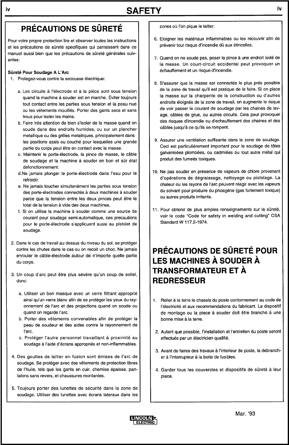
PRINCE® XL TORCH - 25’- P/N K2296-2
Wire Capacity
• .023”-.045” (0.6 - 1.2mm)
solid and hard wire
• .030” - 1/16” (0.8 - 1.6mm)
aluminum and cored wire
Wire Speed
• 750 ipm (19.0 mpm) max.
Duty Cycle - 100%
All ratings are at 25V using Argon Gas
• 200 Amps Air cooled standard, using Air/Water barrel
Torch weight (less leads & standard barrels)
• 36.4 oz. (1.02 kilogram)
PRINCE® XL SPOOL GUN - 25’ - P/N K2297-2
Wire Capacity
• .023” - .045” (0.6 - 1.2mm)
solid and hard wire
• .030” - 1/16” (0.8 - 1.6mm)
aluminum and cored wire
Wire Speed *
• 750 ipm (19.0 mpm) max.
Spool Size
• 4 inches (101.6mm)
Duty Cycle - 100%
All ratings are at 25V using Argon Gas
• 200 Amps Air cooled standard, using Air/Water barrel
Torch weight (less wire & leads)
• 46.5 oz (1.3 kilogram)
* Maximum ipm varies depending on input voltage, wire size
and the control box used.
SUPPORT EQUIPMENT REQUIRED
• CV or CC power source of suffi cient capacity for your needs.
• Regulated gas supply and hoses.
• Properly sized power leads from power source to wire feeder and
ground.
TORCH LEAD CONNECTIONS
POWER CABLE - AIR COOLED
A #2 AWG power cable is used on the Prince®XL air cooled torch. The torch
end is threaded into the torch body. The power cable fi tting connects to the
Power Block.
(MK P/N 003-1674) when using a Cobramatic® wire feed cabinet. When the
Prince®XL is purchased as a Spool Gun, the power cable comes standard
with a lug connector and should be connected to positive lug of power supply.
CONDUIT
The Prince™XL Torch comes standard with a poly lined conduit, for running
aluminum wire. The longer fi tting with a shallow groove is used on the torch
end. A set screw located on top of the torch handle secures the conduit in
Prince XL® - Owner's Manual - Page 4
place. A small spool liner (MK P/N 003-0198) is used on the spool gun and
held in place by the same set screw.
GAS HOSE
The gas hose is secured over the barbed gas fi tting with a tie wrap. The
cabinet end of the gas hose uses our standard gas fi tting (1/8” - 27 nps),
whereas the spool gun uses a 5/8” - 18 IAA RH male gas fi tting.
ELECTRIC CABLE
A seven conductor control cable is used on the Prince®XL Torch. The torch
end of the control cable is secured to the torch with a boot clamp and
plugged into the pot assembly and micro switch connectors. Slack is left in
the electric cable as it exits the back of the torch to prevent cable breakage.
The cabinet end has a seven pin "W" clocked amphenol connector. See
page 22 for torch electrical connections.
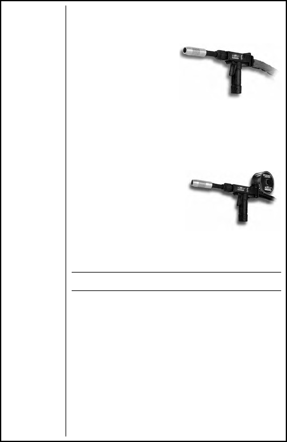
INSTALLING SPOOL ASSEMBLY (P/N 003-2090)
Loosen the screw that secures the conduit through access hole located on
top right rear handle with a 1/16" Allen wrench.
Remove conduit by pulling it out of the back of the gun.
Install spool liner, and secure with screw.
Remove both rear handle screws, and secure spool canister with longer
screws provided.
SPOOL GUN SETUP
LOADING ELECTRODE WIRE
Unscrew, and remove spool cover.
Apply tension to drive rolls, so the wire will be picked up and fed through
the contact tip.
Straighten out fi rst six inches of wire and push through liner.
Jog trigger until wire is picked up by drive rolls and fed through contact tip.
Hold brake assembly back towards top of gun, load spool onto shaft with
wire coming off the bottom of the spool. Release brake assembly to rest
on wire surface.
Replace spool cover, making sure opening is over liner.
Note:
The brake paddle assembly is designed to automatically control spool drag and
keep the wire from jumping off the spool.
SECTION B OPERATION
GENERAL
The Prince™XL torch maintains a constant, steady, uniform wire feed speed,
regardless of curved or looped wire conduit. The constant push exerted by
Conduit Securing Screw
E-Ring Rear Wire Guide
Spool Liner
2 Screws
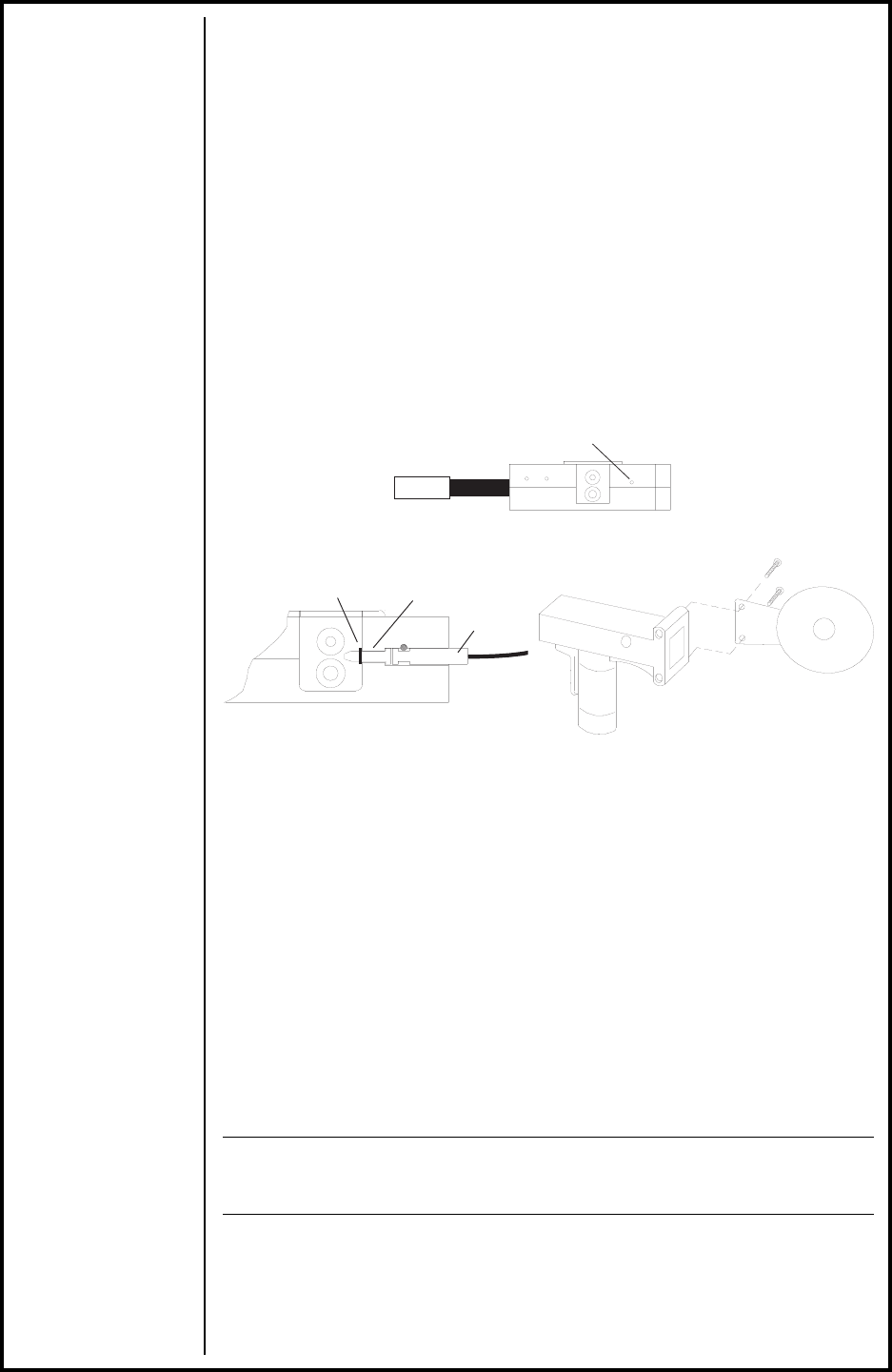
Prince® XL - Owner's Manual - Page 5
ELECTRICAL
CABLE
WIRE CONDUIT
POWER CABLE
PRINCE® XL TORCH
TO
COBRAMATIC® I CABINET
(150-005,150-006, 150-205, 150-206,
K1853-1 & K2259-1)
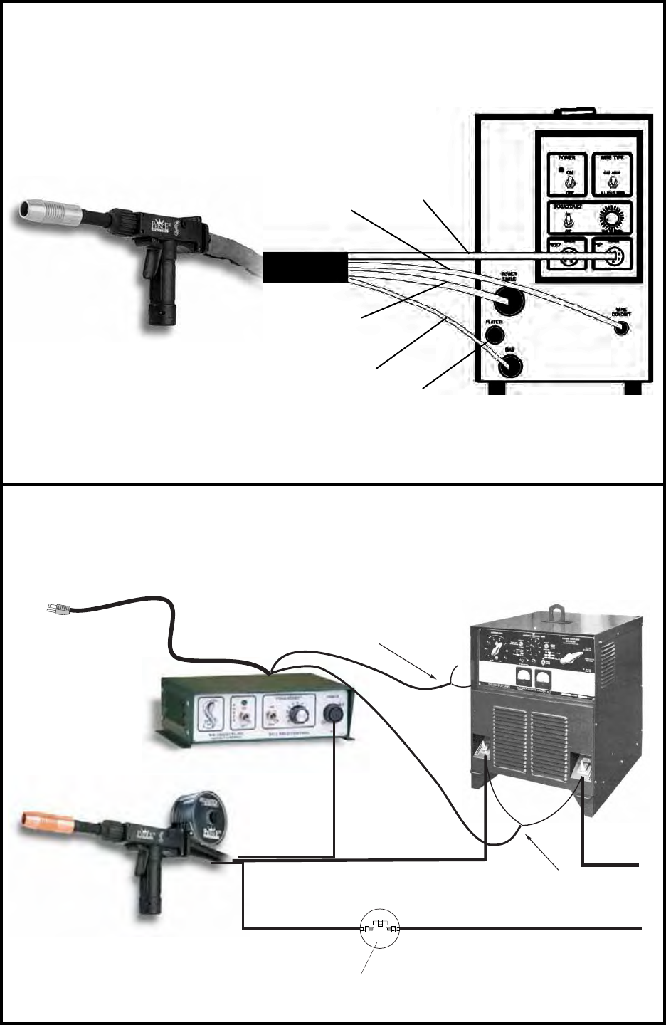
PRINCE® XL SPOOL GUN
TO
WC-1 WELD CONTROL BOX
GAS HOSE
WATER HOSE -
OPTIONAL
INTERCONNECTIONS
GAS HOSE
ELECTRICAL CABLE
115VAC PLUG
POWER CABLE
CONTACTOR LEADS
WC-1 CONSTANT CURRENT
POSA START SENSING LEADS NOT NEEDED
WITH CONSTANT VOLTAGE SUPPLIES
NOTE: The Posa Start feature permits
the WC-1 to be used in
combination with any Constant
Current DC power source with
an open circuit voltage in exces
of 55 volts.
CC or CC POWER SUPPLY
GROUND
Weld Control Box
White
Red Green
Black
Customer Supplied
COUPLER -AW-430-RH
MK P/N 753-3377

Prince XL® - Owner's Manual - Page 6
the slave motor in the cabinet, combined with the pull of the torch motor,
causes the wire to literally fl oat friction-free through the wire conduit. The
24VDC torch motor is controlled by a 3-3/4 turn potentiometer in the torch
handle.
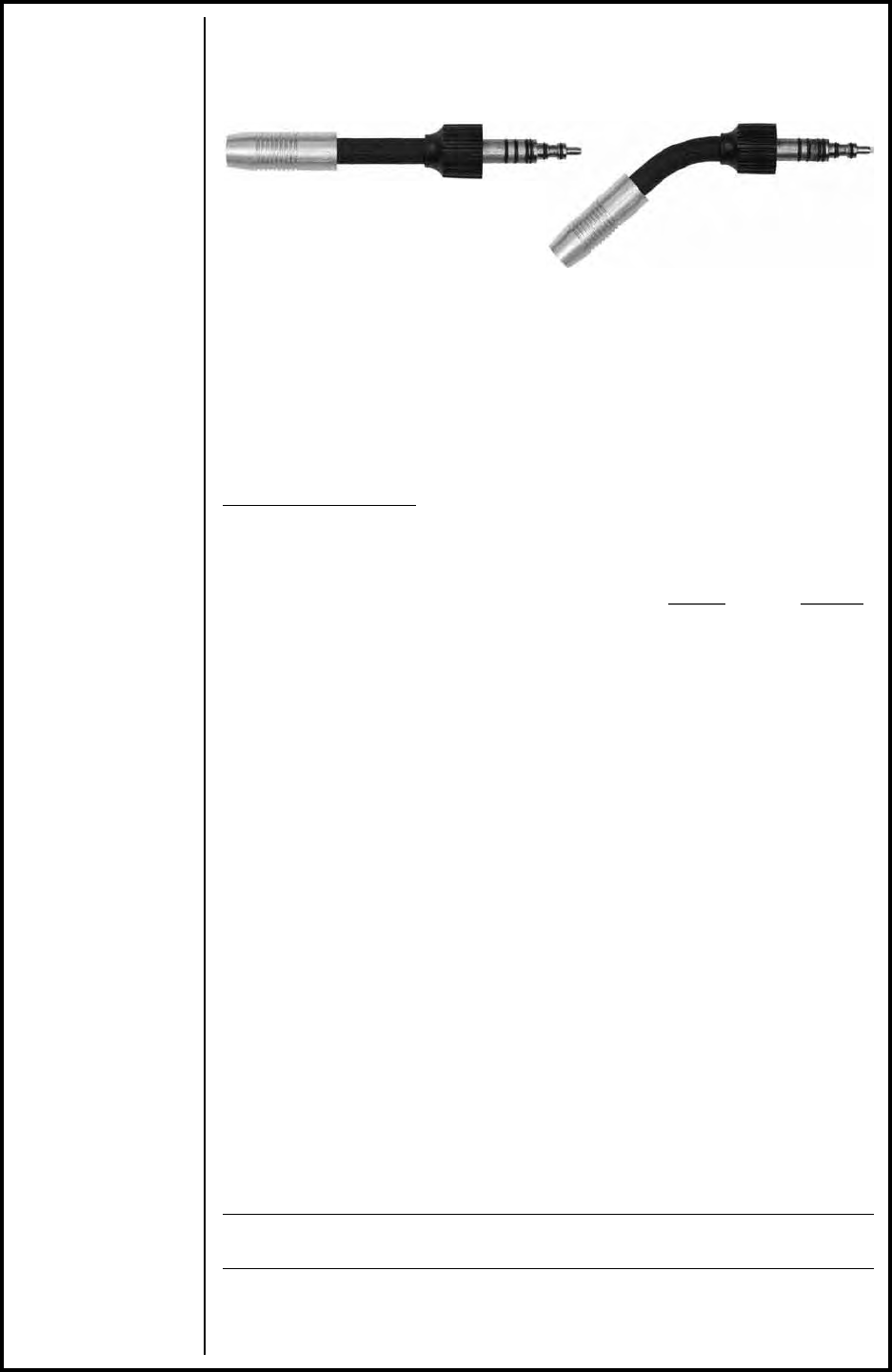
BARRELS
AIR/WATER COOLED
The Prince® XL air cooled systems come standard with a straight air/water
cooled barrel assembly. An optional curved air/water cooled barrel assembly
(LE P/N KP2298-2, MK P/N 003-2152) is also available. In cases where
these barrels need to be extended or the tip threads have been damaged,
a Tip Extender (LE P/N KP2244-1, MK P/N 621-0424) can be adapted. The
same tips and threads can be used, however a longer Tefl on liner (LE P/N
KP2226-1; MK P/N 931-0137) is required.
BARREL REMOVAL AND INSTALLATION
To remove a barrel assembly, loosen the patented EZ Lock™ Taper lock nut
assy MK P/N 003-2572 3/4 to 1 turn. This will push barrel away from the
body far enough so that it may be pulled out of the body.
To replace a barrel assembly, take care not to damage the “O” rings when
inserting into the body. Open the drive and idler roll door and seat the barrel
assembly until the inlet guide is almost touching the drive and idler roll and
the rear face of the barrel is fl ush with the aluminum body block. Tighten
taper lock nut assembly fi rmly so that barrel cannot rotate.
BARREL ROTATION
To rotate a barrel assembly, loosen the patented EZ Lock™ Taper lock nut
assembly no more than 1 turn. Rotate barrel to the position of your choice
and retighten taper lock nut assembly fi rmly so that the barrel cannot rotate.
WARNING:
Do not attempt to weld without the barrel being tightly secured in the torch body, or
damage to the barrel or body may result.
CONTROLS AND SETTINGS
POTENTIOMETER
The pot is located in the bottom of the pistol grip and provides 3-3/4 turns of
rotation and up to 750 ipm.
The pot is mounted to one side of a PC board and is held in place by a
support plate; both of which have slots that locate and secure the pot in the
handles. The other side of the PC board houses the motor connectors and
ribbon cable. Locking disks behind the pot knob provides a stop at the mini-
mum and maximum pot settings.
TRIGGER, GAS VALVE AND MICRO SWITCH
The torch trigger is designed so that when it is partially depressed, gas fl ow
starts via the valve located in the torch body, prior to ignition of the arc. When
the trigger is partially released after welding (extinguishing the arc), gas fl ow
continues until the trigger is fully released; built-in pre and post gas fl ow.
The micro switch is wired “Normally Open” and secured to the torch block
with two (2) screws. An insulator between the torch block and micro switch
prevents accidental shorting of the switch leads. The trigger pin reaches
through the handle and activates the micro switch just before the trigger bot-
toms out on the handle.
Prince XL® - Owner's Manual - Page 7
DRIVE AND IDLER ROLLS
GENERAL
The Prince®XL torch comes standard with knurled drive rolls which will
handle wire diameters from .023 - 1/16 inch. Optional grooved drive rolls are
also available for feeding aluminum wire if desired (see Optional kits).
Drive roll tension is accomplished by means of a pressure adjusting allen
screw located on the left hand side of the torch. Proper tension is achieved
when wire does not slip if a small amount of pressure is added to the wire as
it exits the tip.
----------- IMPORTANT -----------
NOTE: Over-tightening of the drive rolls will cause excessive knurling and/or
deformation of the wire. When the complete system is setup properly, feeding wire
out of the end of the torch and letting fall on the ground should form a large uniform
circle. If it forms a spiral or spring then there is too much tension in the system,
please refer to the Cabinet Owners Manual for adjustment to the tension setting.
INCORRECT DRIVE ROLL TENSION IS THE NUMBER ONE
CAUSE OF POOR WIRE FEED PERFORMANCE
---------------------------------------------
DRIVE ROLL INSTALLATION AND REMOVAL
Note:
Neither of the handles needs to be removed to access the Drive or Idler Rolls.
1. Using a 5/32” hex wrench, loosen the Idler Roll tension screw. This will
relieve the pressure against the drive roll.
2. Align the Drive Roll Removal Tool (P/N 931-0100) over the fl ats of the drive
roll. Hold the torch with one hand or on a table top, with the other hand give
the Removal Tool a quick snap-turn in the CLOCKWISE DIRECTION.
3. Once the drive roll is loose, continue to spin drive roll in the clockwise
direction to remove the drive roll from the torch.
4. Install a new drive roll on the left-hand threaded shaft. The drive roll will
self-tighten when it is feeding wire.
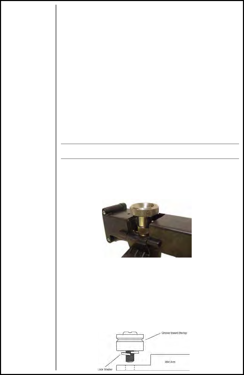
IDLER ROLL INSTALLATION AND REMOVAL
1. Using a slot type screwdriver, loosen idler screw, taking care not to lose
lock washer under idler roll.
2. Insert new idler roll and lock washer onto screw, insuring that idler groove
is toward top and lock washer is beneath.
Prince XL® - Owner's Manual - Page 8
3. Tighten.
4. Using a 5/32” hex wrench, turn the Idler Roll tension screw into the gear-
box housing and reference the Gearbox Assembly drawing to adjust the
pressure against the drive roll.
NOTE:
Lock washer must be under idler roll or it will not turn freely.
SECTION C ACCESSORIES
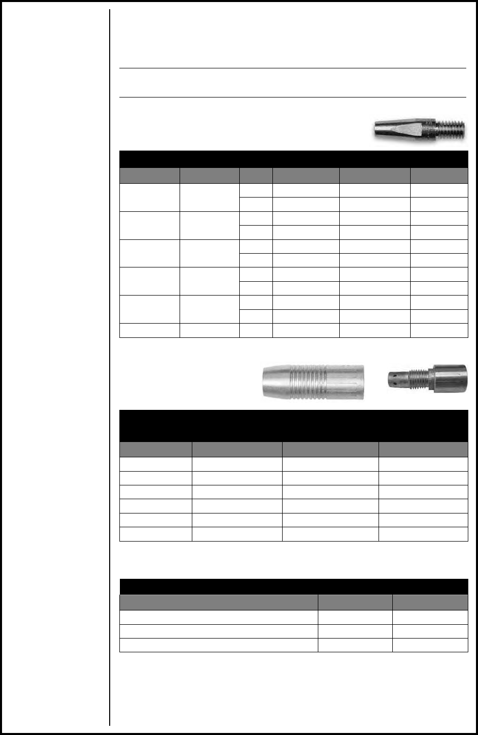
CONTACT TIPS - AIR/WATER BARREL
Contact Tips for Prince
Contact Tips for Prince
®
®
XL Air/Water Cooled Barrels
XL Air/Water Cooled Barrels
Wire Size Tip I.D. Arc Length MK P/N LE P/N
.030” (0.8mm) .040” (1.0mm) Spray 1-5/8” (41.3mm) 621-0390 KP2217-1B1
Short 1-7/8” (47.6mm) 621-0396 --
.035” (0.9mm) .044” (1.1mm) Spray 1-5/8” (41.3mm) 621-0391 KP2217-2B1
Short 1-7/8” (47.6mm) 621-0397 --
.045” (1.2mm) .053” (1.3mm) Spray 1-5/8” (41.3mm) 621-0392 --
Short 1-7/8” (47.6mm) 621-0398 --
.052” (1.3mm) .060” (1.5mm) Spray 1-5/8” (41.3mm) 621-0393* KP2217-4B1
Short 1-7/8” (47.6mm) 621-0399 --
1/16” (1.6mm) .075” (1.9mm) Spray 1-5/8” (41.3mm) 621-0394 KP2217-5B1
Short 1-7/8” (47.6mm) 621-0400 --
1/16” (1.6mm) .085” (2.1mm) Spray 1-5/8” (41.3mm) 621-0395 --
All tips stamped with tip I.D.
*Standard - furnished with torch
FINNED COPPER GAS CUPS
AIR/WATER COOLED BARREL
Finned Copper Gas Cups for
Finned Copper Gas Cups for
Prince
Prince
®
®
XL Air/Water Cooled Torch
XL Air/Water Cooled Torch
Size I.D. MK P/N LE P/N
6 3/8” (9.5mm) 621-0248 KP2213-1
8 1/2” (12.7mm) 621-0249 KP2214-1
10 5/8” (15.8mm) 621-0250* KP2215-1
10 H.D. 5/8” (15.8mm) 621-0251 KP2216-1
12 H.D. 3/4” (19.0mm) 621-0252 --
N/A Tip Extender 621-0424 KP2244-1
*Standard - furnished with torch
TORCH BARREL LINERS
Prince
Prince
®
®
XL Torch Barrel Liners
XL Torch Barrel Liners
Description MK P/N LE P/N
Tefl on liner package, 5 pieces 931-0137 KP2226-1
Bulk tefl on liner material for .030-.063” (.8-1.6mm) 615-0178 ---
Bulk tefl on liner material for .030-.035” (.8-.9mm) 615-0177 ---
Tip Extender
Prince XL® - Owner's Manual - Page 9
BARREL ASSEMBLIES
OPTIONAL 12” AND 18” WATER COOLED STRAIGHT AND CURVED
BARREL ASSEMBLIES
12” Straight Air/Water Cooled Barrel Assembly . . . . . . . . . . 003-2156
12” Curved Air/Water Cooled Barrel Assembly . . . . . . . . . . 003-2158
18” Straight Air/Water Cooled Barrel Assembly . . . . . . . . . . 003-2157
18” Curved Air/Water Cooled Barrel Assembly . . . . . . . . . . 003-2159
OPTIONAL KITS
Insulated drive roll kits are used to prevent preheating of the wire which may
soften it and clog the liner. This picking up of current at the drive rolls rather
than at the contact tip is usually not a problem usless using too large of a
contact tip or excessively oxidized aluminum wire.
LE P/N MK P/N
Insulated Groove Drive Roll Kit..........................KP1594-030....... 005-0640
For .030" (0.8mm) dia. aluminum wire. Includes insulated
drive roll P/N 511-0150 and idler roll assy. P/N 003-2097.
Insulated Groove Drive Roll Kit......................... KP1594-035 ...... 005-0641
For .035" (0.9mm) dia. aluminum wire. Includes insulated
drive roll P/N 511-0151 and idler roll assy. P/N 003-2097.
Insulated Groove Drive Roll Kit...................................................... 005-0642
For .040" (1.0mm)dia. aluminum wire. Includes insulated
drive roll P/N 511-0152 and idler roll assy. P/N 003-2097.
Insulated Groove Drive Roll Kit......................... KP1594-3/64 ...... 005-0643
For .045" (1.2mm) dia. aluminum wire. Includes insulated
drive roll P/N 511-0153 and idler roll assy. P/N 003-2097.
Insulated Groove Drive Roll Kit......................... KP1594-1/16 ...... 005-0644
For .062" (1.6mm) dia. aluminum wire. Includes insulated
drive roll P/N 511-0154 and idler roll assy. P/N 003-2097.
OPTIONAL ACCESSORIES
Conduits
Flat Spiral Steel Conduit Standard Conduit
for steel & cored wire. with additional protective cover.
615-0208 ................15 ft./4.5m 001-0774................ 15 ft./4.5m
615-0216 ................25 ft./7.6m 001-0775................ 25 ft./7.6m
615-0218 ................50 ft./15.2m 001-1278................ 35 ft./10.5m
001-0777................ 50 ft./15.2m
NOTE:
The protective cover is used to help protect the conduit from burns.
25' 7 Pin Amphenol Extension Cable . . . . . . . . . . . . . . . . . (MK) 005-0660
Used to extend the spool gun. Two cables may be joined together for 50'
extension. Power & gas cables not included.
OPTIONAL
Curved, 003-2152
STANDARD
Straight, 003-2151
ALL BARRELS RATED AT 100% DUTY CYCLE
Prince XL® - Owner's Manual - Page 10
Snake Skin® zipper cover
Leather Snake Skin® protective covers are now standard on all torches.
Replacement covers may ordered to protect the lead assembly of the torch
when the original factory cover becomes damaged or worn. The Velcro®
closure makes it easy to replace in the fi eld.
13' cover fi ts 15' lead (MK) 931-0110
23' cover fi ts 25' lead (MK) 931-0122
48’ cover fi ts 50’ lead (MK) 931-0123
Prince® XL Handle Kit .......................................................(MK P/N) 005-0633
Includes left and right handle with door, trigger and pin, and all handle
screws.
Heavy Duty Brake Spring for hardwires ...........................(MK P/N) 005-0682
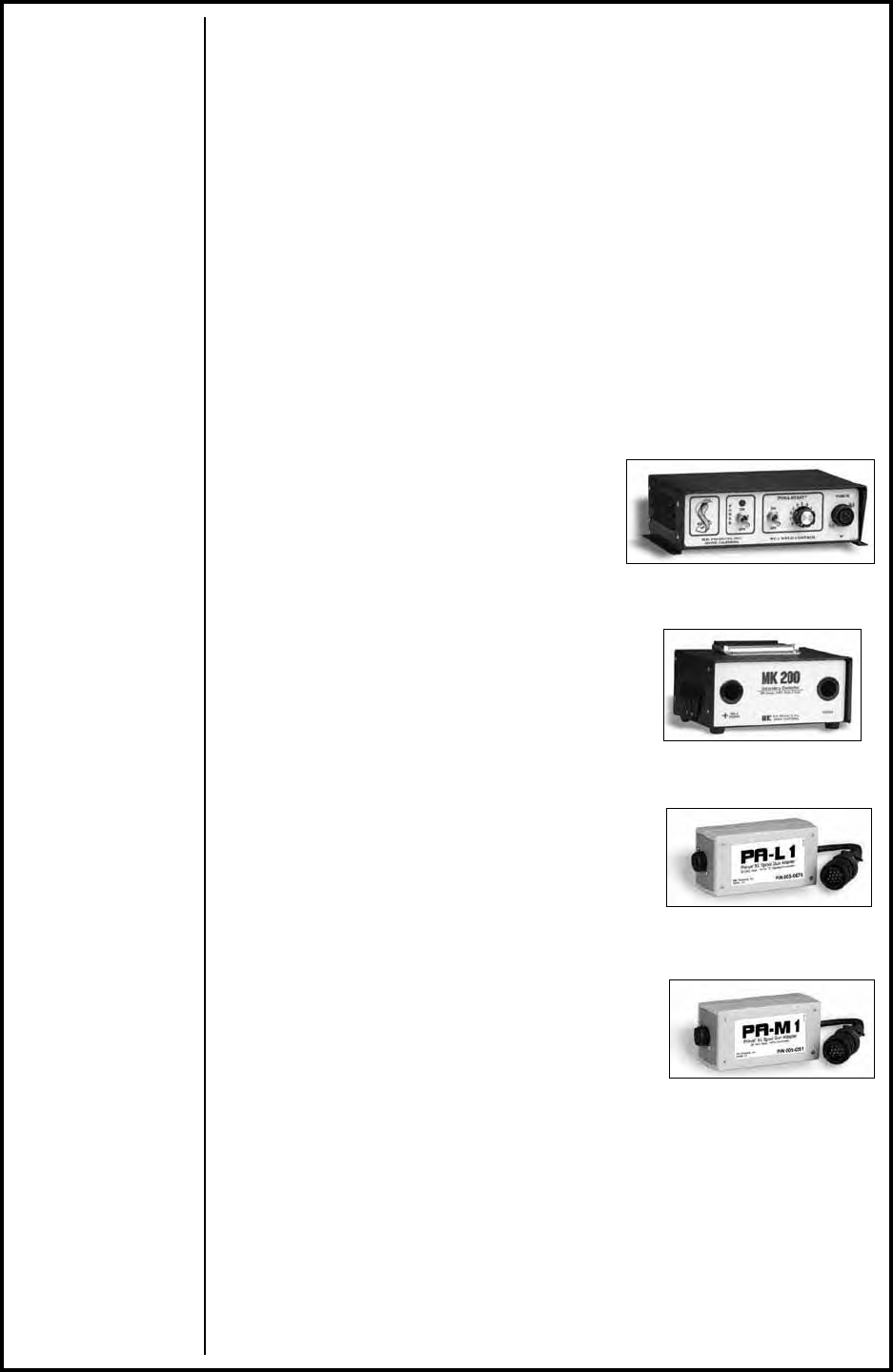
PRINCE® SPOOL GUN CONTROLS
WC-1
P/N 001-3062
The WC-1 is desinged to hookup to any CV
or CC power supply having its own contactor.
CC Posa Start “run-in speed” is included as
a standard feature. The control operates on
115VAC, 50-60hz power. For macines such
as gas drives that do not have contactors,
the MK200
Contactor Box (P/N 001-3066) must be used.
MK200 CONTACTOR BOX
P/N 001-3066
PA-L1 SPOOL GUN CONTROL - LINCOLN
P/N 005-0676
Connects directly to Lincoln Electric power
supplies (42V system) with 14-Pin (X-clocked)
amphenol connectors, such as:
CV 250 CV 300 CV 400
CV 655 DC 400 DC 600
DC 655 V350-Pro (factory model) Ranger 250
Range 275 Ranger 305G
PA-M1 SPOOL GUN CONTROL - MILLER
P/N 005-0261
Connects directly to Miller power supplies (24V
system) that are classifi ed with 14-Pin amphenols
as type 6 or 9 and to Thermal Arc units, such as:
MILLER SUPPLIES THERMAL ARC
Millermatic 200 Deltaweld's Thermal Arc 300GMS CC/CV
Shopmaster CP Series Fabricator 210, 250, 300 LF
XMT's & Maxtron Trailblazer 250, 251
Regency's
Any Gas-drive that has a CV tap and contactor installed with a 14 pin amphenol.
WC-1
MK200 Contactor Box
Spool Gun Control - Lincoln
Spool Gun Control - Miller
Prince XL® - Owner's Manual - Page 11
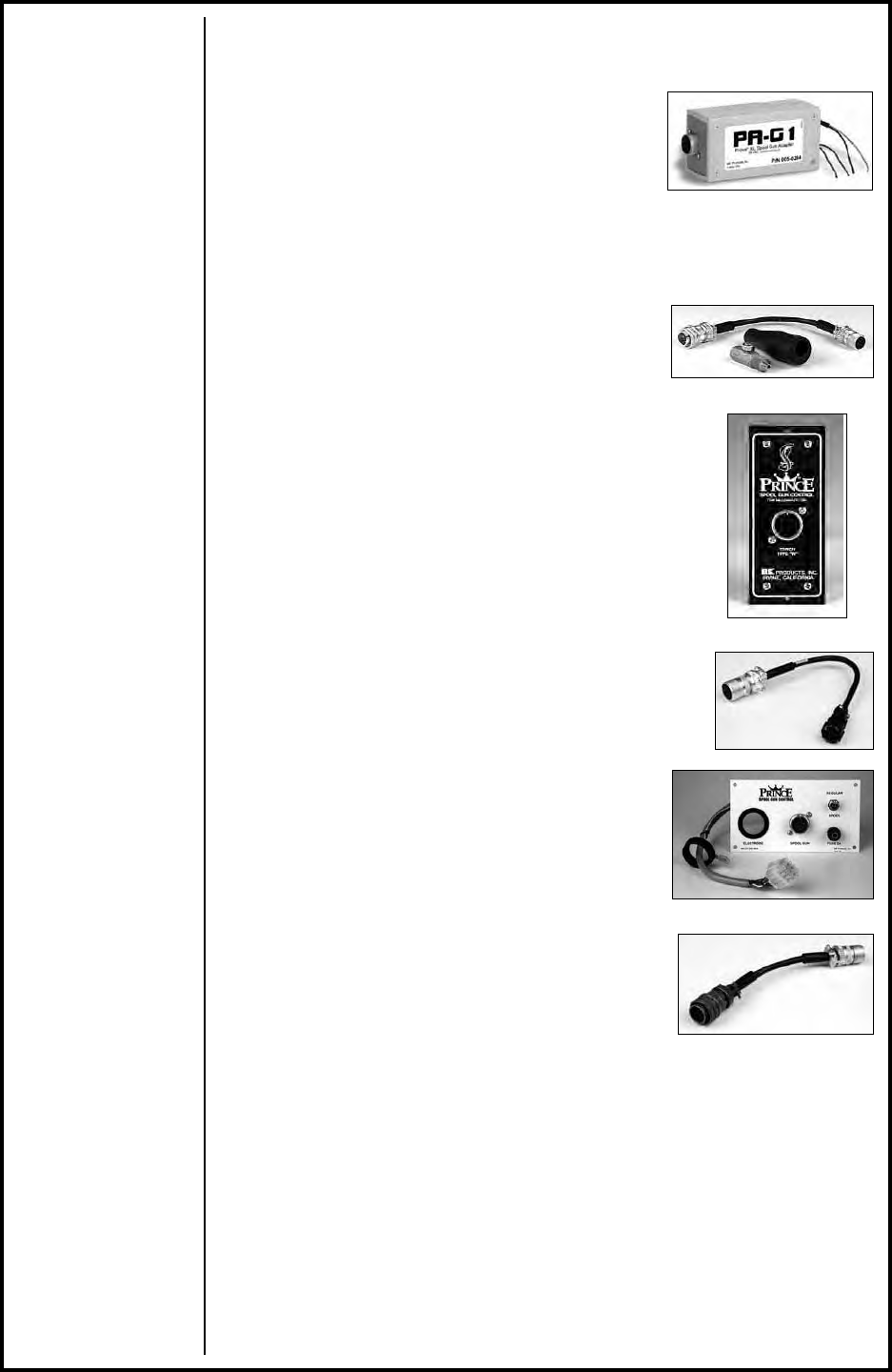
PA-G1 SPOOL GUN CONTROL - GENERIC
P/N 005-0264
This Generic Torpedo is designed to hook-up to
CV power supplies that supply an auxiliary 26 VAC
@ 1.7 amps and uses a closing contact signal.
The unit is supplied with bare wires that must be
connected to the power supply. Some examples
of power supplies that can be hooked-up are:
Lincoln SP-250, 255 & Wirematic 250 & 255
Beta-Mig 200 & Beta-Mig LF
Airco Dip-Pak 200, 225 & 250
ESAB (L-TEC) / MIGMASTER 250
P/N 005-0206
An amphenol adaptor cable and gas/power lug
are all that is needed to connect to the Migmaster.
Adaptor kit includes everything needed.
MILLERMATIC 250 & VINTAGE / HOBARTS BETAMIG 2510
P/N 005-0205
This easy to install, plug in module fi ts the Millermatic
250, Miller Vintage machine, or Hobart Betamig 2510.
It and a Prince Spool Gun are all that is needed to get
your customer up and running.
PANASONIC GUNSLINGER 260
P/N 005-0617
Easy to install adapter cable using Gunslinger speed
control.
ESAB MIGMASTER 251
P/N 005-0624
A panel kit plugs directly into the front of the
MigMaster 251 and includes everything that is
needed to interface the spool gun.
MILLERMATIC 250X
P/N 005-0629
Easy to install adapter cable using MillerMatic 250X
speed control.
FABRICATOR 250
P/N 005-0689
Easy to install adapter cable using MillerMatic 250X
speed control.
ESAB (L-Tec-Linde) MigMaster 250
Spool Gun Control - Generic
MillerMatic 250, Vintage and BetaMig 2510
MillerMatic 250X
Fabricator 250
Panasonic Gunslinger 260
ESAB MigMaster 251
Prince XL® - Owner's Manual - Page 12
SECTION D MAINTENANCE
PERIODIC MAINTENANCE
Maintenance of the torch will normally consist of a general cleaning of the
wire guide system, including tubes, drive rolls, and conduits at regular inter-
vals.
Remove spatter build-up from inside of nozzles with a hardwood stick.
The only parts on the Prince® XL that are subject to normal wear are the
conduit, contact tips, gas cups, barrel liners, drive and idler rolls. A supply of
these parts should be maintained on hand.
If repairs do become necessary, qualifi ed shop maintenance personnel can
easily replace any part.
Your Cobramatic System is designed to provide years of reliable service.
Normal wear and component failure may require occasional service.
The number of units in operation and the importance of minimal “down time”
will determine to what extent spare parts should be stocked on hand. See the
“Recommended spare parts list” for the most commonly replaced parts.
Maintenance Tools
Tool MK P/N
Gas Valve Removal Tool 931-0584
Contact Tip Removal Tool 931-0002
Drive Roll Removal Tool 931-0100
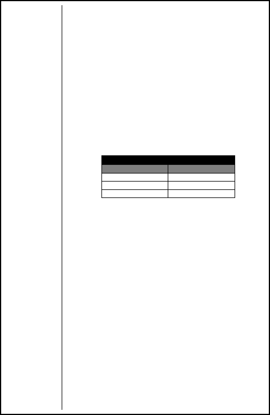
Prince® XL - Owner's Manual - Page 13
Idler Roll
(MKP/N) 511-0001
(LE P/N) KP2220-1
Drive Roll
(MKP/N) 511-0101
(LE P/N) KP2219-1
Micro Switch
161-0002
Recommended Spare Parts List
Part Number Description Part Number Description
615-0007 Conduit 15’ 325-0206 Idler Roll Screw
615-0008 Conduit 25’ 333-0082 Idler Roll Washer
005-0661 Potentiometer Kit 003-0585 Trigger Asy.
003-0568 Micro Switch 431-3117 Door
005-0633 Handle Kit 003-0198 Wire Guide-Spool Gun
(MK) 511-0101
(LE) KP2219-1 Drive Roll 003-2072 Brake Assy.-Spool Gun
(MK) 005-0686
(LE) KP2220-1 Idler Roll 003-2071 Cover Assy.-Spool Gun

Prince XL® - Owner's Manual - Page 14
SECTION E TROUBLESHOOTING
Regardless of which torch or feeder used, all MK Products push-pull guns
operate on the same principle. The 115 VAC or 42VAC slave motor in the
feeder runs at a fast, constant speed, but has very low torque. It is always
trying to feed more wire than the torch motor wants, and when the motor gets
all it wants, it slows the slave motor, preventing a bird’s nest. Because of the
low torque produced by the slave motor, a brake system is used to prevent
wire overrun rather than tension.
The 24 VDC torch motor is controlled by a solid state speed control and a
pot located in the torch. The torch motor, potentiometer, and micro switch
are connected to the cabinet/control box via a control cable and amphenol. If
this cable becomes damaged, a variety of symptoms can occur, depending
on which wire(s) break. To test, check each wire for continuity and shorts.
With the increased torque rating in the current Prince XL motor, P/N 211-
0071, it now draws about twice as much current on start-up as the original
Prince motors P/N’s 211-0054 & 211-0056. Even though the duration of
start-up is very short, about 15msec, it is too much for the standard 2A fuse
to handle. For this reason, all 2A fuses in the motor circuitry (F1) should be
changed to a 3AG 4A fast blow 250V fuse, P/N 151-0043. This new 4A fuse
is suffi cient for use on all model welding guns on the wire feeders, while still
providing protection for the circuitry from any shorts in the motor or motor
leads.
This fuse change includes all Cobramatic, Cobramatic II and CobraMig 250/
260, WC-1, Torpedo’s, and any other motor circuits powering Prince XL or
Spool Guns using motor P/N 211-0071.
Remember the micro switch in the torch activates both the 115 VAC or 42
VAC and 24 VDC circuits in the cabinet. Therefore, if the slave motor and
brake solonoid operate, but the torch does not, look more toward the 24 VDC
circuits, speed control, control cable, or the torch motor. If nothing operates,
look more toward the 115 VAC or 42 VAC input, micro switch leads, or micro
switch.
The complete pot assembly is connected to the motor and set into the
handles. If the pot is disassembled, the pot knob can be put on the shaft in
any position and secured with the set screw. Turn the knob fully CCW, then
fully CW, then fully CCW again. This will self-align the pot, i.e., fully CCW will
be minimum wire feed speed, and fully CW will be maximum wire speed.

Prince® XL - Owner's Manual - Page 15
Troubleshooting Guide
Trouble Cause Remedy
No wire feed at torch, feeder no
operating, i.e. no slave motor or brake
solenoid.
115/42VAC control fuse in feeder. Replace fuse.
Micro-switch defective/not being
activated.
Replace switch. Check switch for
operation.
Broken electrical cable. Check micro-switch wires for continuity.
No wire feed at torch, feeder operating
properly.
4 amp fuse (F1) in feeder/Control box
blown.
Check motor leads for shorts; then
replace fuse.
Bad potentiometer. Check potentiometer with meter.
Broken electrical cable. Check motor and potentiometer wire
for continuity.
Bad speed control/PCB See specifi c cabinet/control box owners
manual for speed control operation.
Wire feeds, but welding wire is not
energized.
Loose or no cable connections. Check all power connections.
Contactor control cable loose or in
wrong position.
Check power supply owner’s manual
for location and type of contactor signal
required, i.e., closing or 115 VAC.
Welding power source. Check power source material.
Wire feeds erratically.
Dirty or worn conduit. Blow out or replace conduit.
Incorrect ressure on drive rolls. Adjust pressure at both feeder and
torch.
Idler roll stuck. Check for lock washer under idler roll,
or replace if damaged.
Wrong size contact tip. See contact tip table.
Wire feeds one speed only.
Bad potentiometer. Check with meter.
Broken electrical cable. Check potentiometer wires for
continuity or short.
Bad speed control. See specifi c cabinet/control owner’s
manul for speed control operation.
Wire walks out of drive rolls. Idler roll upside-down. Place groove in idler roll toward top.
Rear wire guide missing. Replace wire guide.
Poor gas/water fl ow. Incorrect placement of barrel insulator.
Slide barrel insulator downa nd thread
until it bottoms out, covering coolant
ports and exposing gas ports.

Prince XL® - Owner's Manual - Page 16
TESTING THE TORCH
MOTOR CHECK
Remove the torch connector from the cabinet.
Using the torch Amphenol, check the resistance across pins “A” and “B”
(motor leads). The resistance across the motor should be between 5-10
ohms.
If an open circuit or short exist, check the motor leads and motor indepen-
dently.
TESTING THE POTENTIOMETER
Using the torch Amphenol, check the resistance across pin “D” (wiper) and
pin “C”. The resistance should vary from 0 - 5K ohms.
Check the resistance across pin “D” (wiper) and pin “G”. The resistance
should vary from 5K - 0 ohms.
TESTING THE MICRO SWITCH
Using the torch Amphenol, check for continuity across pins “E” and “F” when
the trigger is pressed.

Prince XL® - Owner's Manual - Page 17
SECTION F APPENDICES
DIAGRAMS/PARTS LISTS
K2296-2 (LE) / 313-725 (MK) PRINCE ® XL EXPLODED VIEW .......18
003-1972 (MK) Head Body.......................................19
K2297-2 (LE) / 316-725 (MK) Spool Gun (25ft) ................20
KP2298-1 (LE) / 003-2151 (MK) 7” Air/Water Cooled
Straight Barrel Assembly ....................................21
KP2298-2 (LE) / 003-2152 (MK) 7”Air/Water Cooled
45° Barrel Assembly .........................................22
Air Cooled Lead Assembly ......................................23
Spool Gun Lead Assemlby ......................................24
Electrical Control Cable.........................................25
Electrical Schematic.............................................26
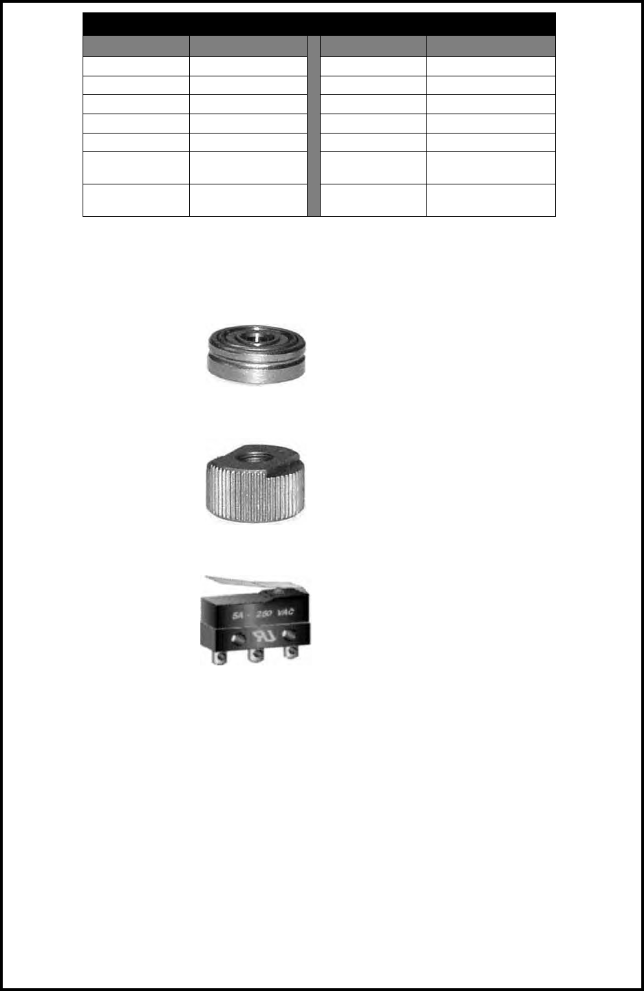
Prince® XL - Owner's Manual - Page 18
PRINCE® XL EXPLODED VIEW
MK P/N 313-725
LE P/N K2296-2
Prince® XL, Air Cooled
dwg 001-1346c
No. Qty. Part No. Description
1 1 001-1144 Lead 25ft Air Cool 7W
2 1 003-0567 Assy Potentiometer PXL
3 1 003-0585 Assy Trigger PXL
4 1 003-1972 Assy Body PXL
5 1 003-1974 Clamp Leads PXL
61
LE KP2298-1
MK 003-2151 Assy Barrel Str A/W PXL
7 7 153-0852 Pin
8 1 153-0856 Connector Molex 2 Pos
9 1 153-0857 Connector Molex 5 Pos
10 1 211-0071 Motor
11 3 328-0003 Screw Shc 4-40 x 0.50
12 4 333-0003 Wshr Spr Lk #4
13 2 333-0005 Wshr Spr Lk #6
14 2 336-0049 Screw Pnhd Ph 4-40 x 0.625 St
15 2 336-0056 Screw Pnhd Ph 4-40 x 1.50 St
16 2 336-0070 Screw Pnhd Ph 6-32 x 1.50
17 1 405-0706 Label Serial Number
18 1 411-0045 Tie Wrap
19 1 421-0408 Pin Dowel Ø0.093 x 2.00 LG
20 1 421-0409 Pin Dowel Ø0.093 x 1.25 LD
21 1 431-3117 Door PXL
22 1 435-3124 Spring Door PXL
23 1 436-0136 Handle Right SS PXL
24 1 436-0137 Handle Left SS PXL
25 1 437-0237 Spacer Handle PXL
26 1 511-0101 Driveroll Gold
27 1 751-0020 Cap Plug 0.218 ID x 0.50 LG
28 A/R 823-0029 Anti-Corrosion Compound
29 A/R 823-0050 Thread Locking Cmpd Low Str
30 A/R 835-0006 Lubricant Silicon
Prince® XL - Owner's Manual - Page 19
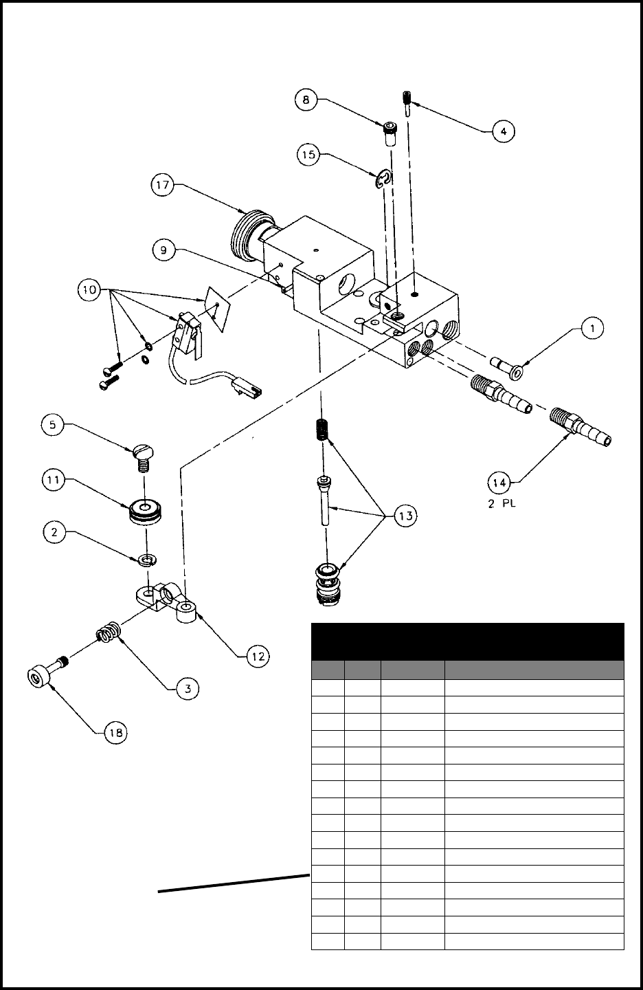
HEAD BODY, EXPLODED VIEW
MK P/N 003-1972C
Note 2: If Cobramatic Wire Feeder is
equipped with a gas solenoid kit, a
modifi ed gas value stem (p/n 431-1080)
must be installed in torch to allow gas
fl ow from cabinet value.
Head Body
003-1972c
No. Qty. Part No. Description
1 1 431-2013 Wire Guide
2 1 333-0082 Washer Split 10
3 1 419-0020 Spring Compress 0.29 OD x 0.047
4 1 321-1074 Set Scr mod 6-32unc x 5/8
5 1 325-0206 Screw Pan Head 10-24-3/8
8 1 431-1427 Pivot Pin
9 1 421-0129 Pin Spring 0.063 x 0.437
10 1 003-0568 Micro Switch Assy.
11 1 511-0001 Idler Wire Feed Assy.
12 1 431-1424 Idler Arm
13 1 001-0562 Gas Valve Cobra
14 1 431-3034 Fitting 3/16 hose to 1/16-27npt
15 1 313-0008 E-ring Shaft 0.188
17 1 002-0573 Main Body Assy.
18 1 002-0583 Adjust Screw Idler Arm
19 A/R 823-0044 Sealand, Pipe Thread
Item numbers 6, 7, and 16 are not used.
Note 1: Item numbers 2, 5, and 11 can
be purchased as Kit (MK P/N) 005-0686
or (LE P/N) KP2220-1
Prince® XL - Owner's Manual - Page 20
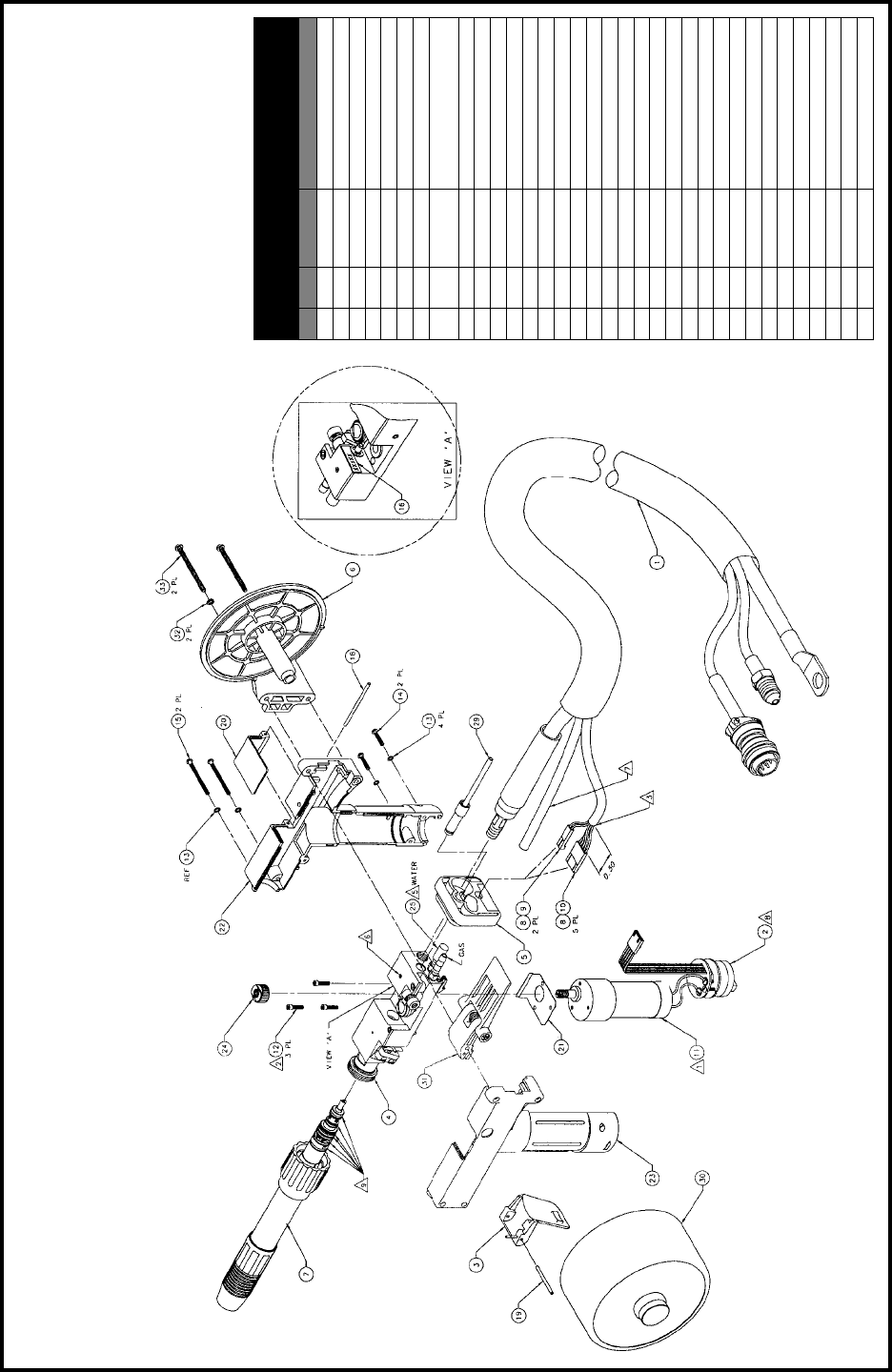
PRINCE® XL SPOOL GUN EXPLODED VIEW
MK P/N 316-725
LE P/N K2297-2
Spool Gun
dwg. 001-1375c
No. Qty. Part No. Description
1 1 001-1317 Lead 25ft Spool Gun 7W
1 1 001-1318 Lead 50ft Spool Gun 7W
2 1 003-0567 Assy potentiometer
3 1 003-0585 Assy Trigger
4 1 003-1972 Assy Body
5 1 003-1974 Clamp Leads
6 1 437-0235 Spindle
71
LE KP2298-1
MK 003-2151 Assy Barrel Str A/W
8 7 153-0852 Pin
9 1 153-0856 Connector Molex 2 Pos
10 1 153-0857 Connector Molex 5 Pos
11 1 211-0071 Motor
12 3 328-0003 Screw Shc 4-40 x 0.50
13 4 333-0003 Wshr Spr Lk #4
14 2 336-0049 Screw Pnhd Ph 4-40 x 0.625 St.
15 2 336-0056 Screw Pnhd Ph 4-40 x 1.50 St.
16 1 405-0706 Label Serial Number
17 1 411-0045 Tie Wrap
18 1 421-0408 Pin Dowel Ø0.093 x 2.00 LG
19 1 421-0409 Pin Dowel Ø0.093 x 1.25 LD
20 1 431-3117 Door
21 1 435-3124 Spring Door
22 1 436-0136 Handle Right SS
23 1 436-0137 Handle Left SS
24 1 511-0101 Driveroll Gold
25 1 751-0020 Cap Plug
26 A/R 823-0029 Anti-Corrosion Compound
27 A/R 823-0050 Thread Locking Cmpd Low Str
28 A/R 835-0006 Lubricant Silicon
29 1 003-0198 Wire Guide
30 1 003-2089 Assy Cover
31 1 003-2072 Assy Brake
32 2 333-0005 Washer Lock #6
33 2 336-0073 Scr Pan Hd Phil 6-32 x 2.00 St
Prince® XL - Owner's Manual - Page 21
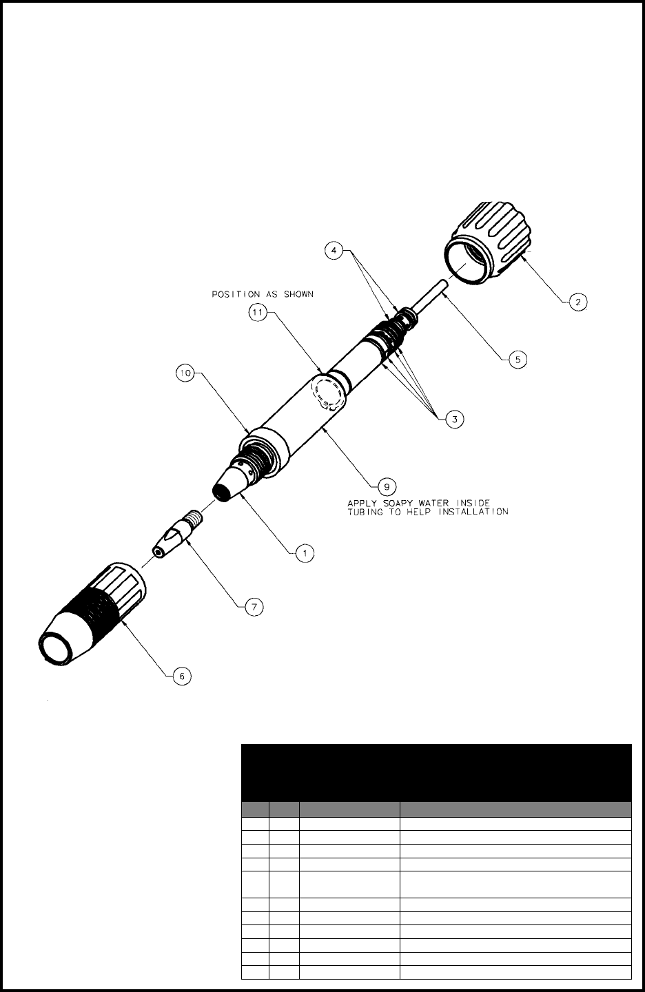
STRAIGHT, AIR/WATER COOLED BARREL ASSY. 7”, EXPLODED VIEW
LE P/N KP2298-1, MK P/N 003-2151
200 AMP, 100% DUTY CYCLE
Straight Air/Water Cooled
Barrel Assy.
003-2151
No. Qty. Part No. Description
1 1 002-0642 Brazed Barrel Str AW
2 1 003-2213 Assy Taper Lock
3 4 303-0010 O-Ring 0.489 ID x 0.070 OD
4 2 303-0094 O-Ring 0.301 ID x 0.070 OD
51 LE KP2226-1
MK 931-0137 Tefl on Liner Package, 5 Pieces
6 1 621-0250 Assy Cup Cpr Finned #10
7 1 621-0393 Tip HD Spray 0.060
8- - -
9 1 005-0696 Insulator Replacement Kit
10 1 431-1774 Cup Insulator
11 1 313-0091 Retaining Ring 5/8 Shaft
Prince® XL - Owner's Manual - Page 22
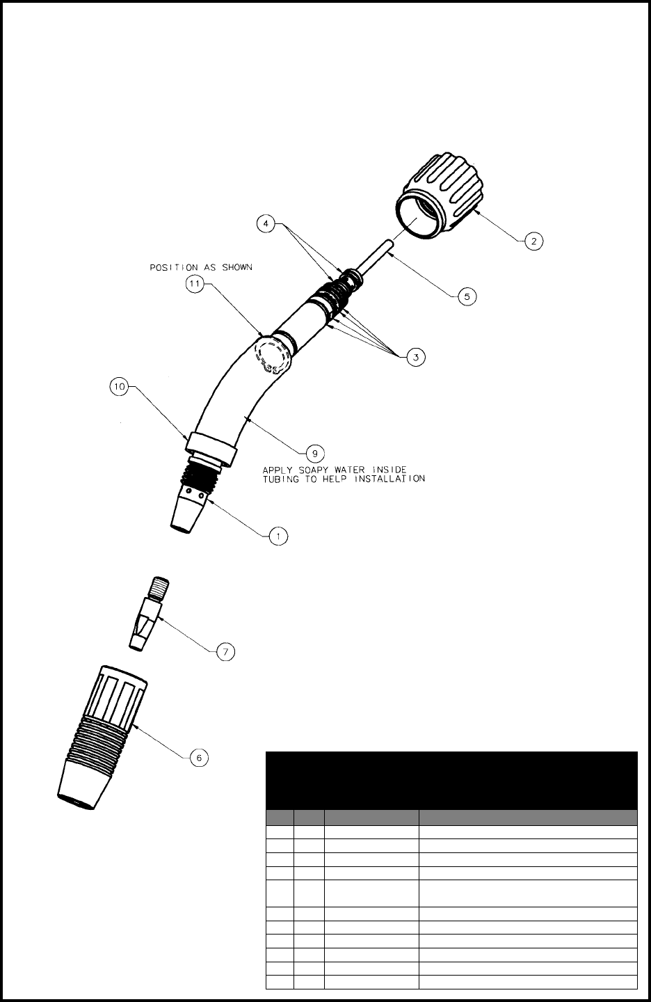
45° CURVED, AIR/WATER COOLED BARREL ASSY. 7”, EXPLODED VIEW
LE P/N KP2298-2, MK P/N 003-2152
200 AMP, 100% DUTY CYCLE
45° Curved Air/Water Cooled
Barrel Assy
003-2152
No. Qty. Part No. Description
1 1 002-0670 Assy Bend Barrel 45° AW
2 1 003-2213 Assy Taper Lock
3 4 303-0010 O-Ring 0.489 ID x 0.070 Width
4 2 303-0094 O-Ring 0.301 ID x 0.070 Width
51 LE KP2226-1
MK 931-0137 Tefl on Liner Package, 5 Pieces
6 1 621-0250 Assy Cup Cpr Finned #10
7 1 621-0393 Tip HD Spray 0.060
8- - -
9 1 005-0696 Insulator Replacement Kit
10 1 431-1774 Cup Insulator
11 1 313-0091 Retaining Ring 5/8 Shaft
Prince® XL - Owner's Manual - Page 23
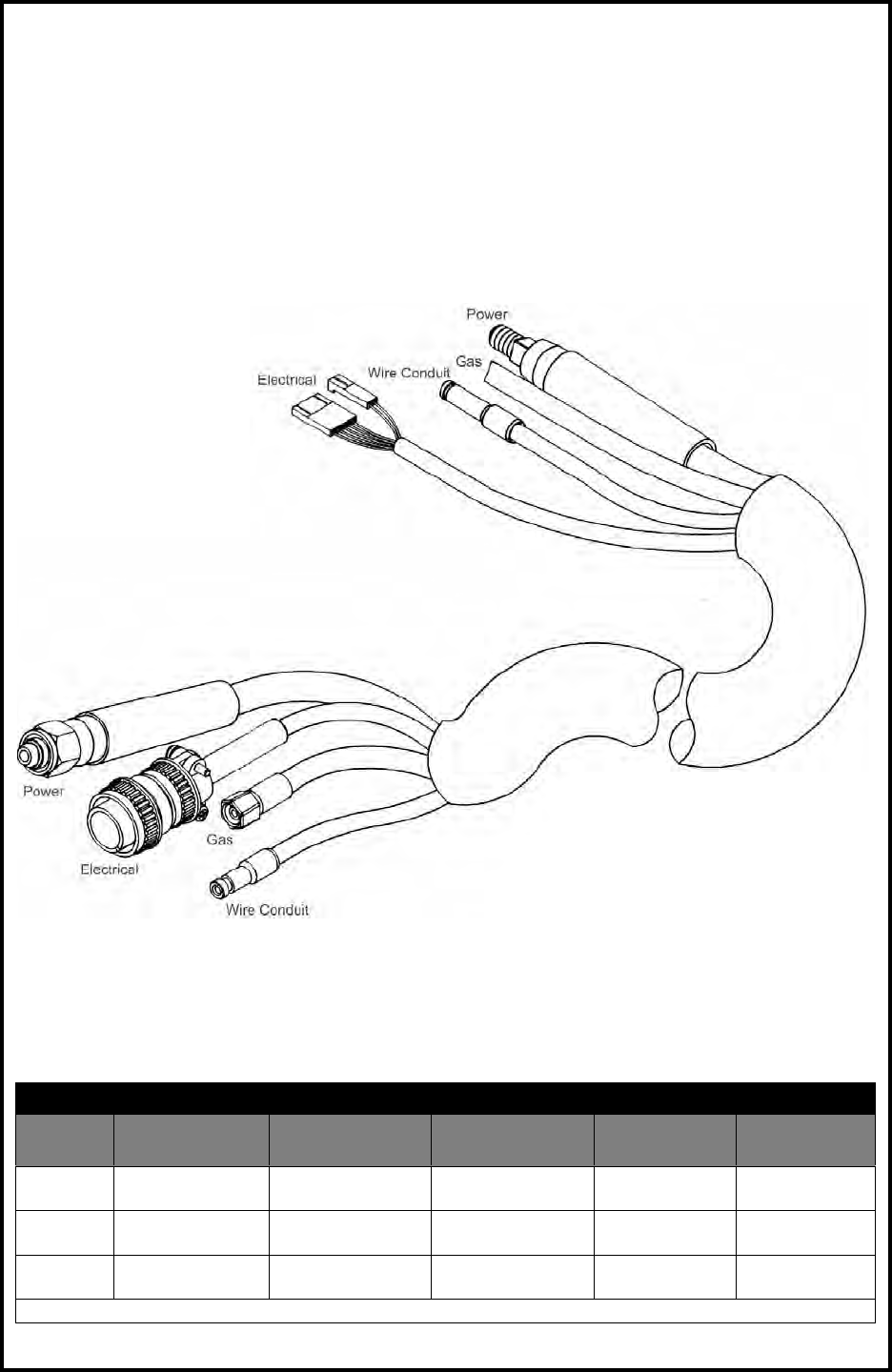
AIR COOLED LEAD ASSEMBLY
Prince® XL Air Cooled Cable Assemblies
Length LE P/N Conduit
(MK P/N) #2 Pwr Cable* Electrical
Cable* Gas Hose* Snake Skin*
15’/4.5m KP2072-30
(615-0007) 001-2527 005-0268 001-0537 931-0110
25’/7.6m KP2072-28
(615-0008) 001-2528 005-0269 001-0538 931-0122
50’/15.2m KP2072-29
(615-0068) 001-1042 005-0272 001-0665 931-0123
*MK part numbers
Prince® XL - Owner's Manual - Page 24
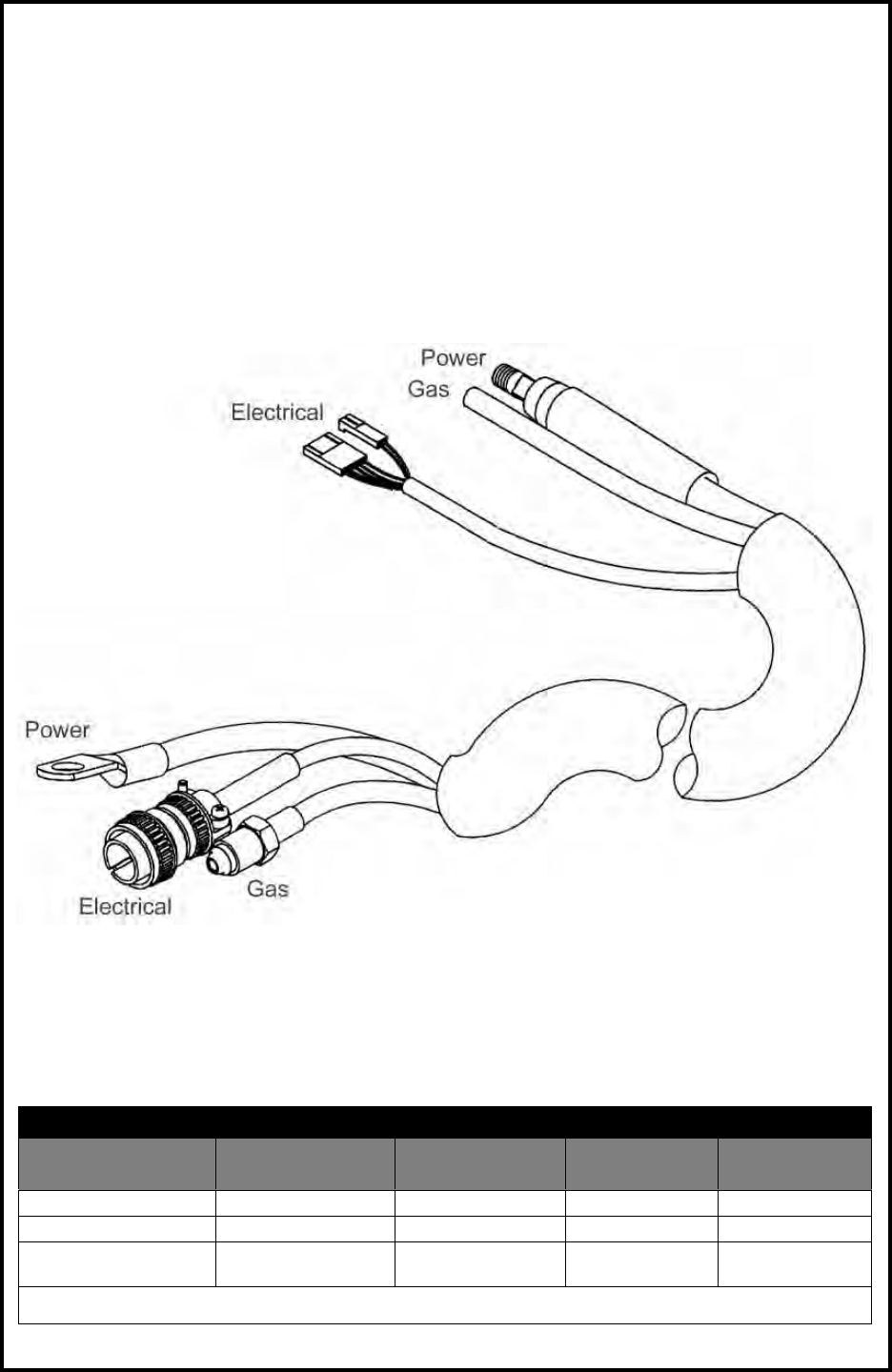
SPOOL GUN LEAD ASSEMBLY
Spool Gun Lead Assemblies
Length #2 Power Cable* Electrical
Cable* Gas Hose* Snake Skin*
25’/7.6m 843-0484 005-0269 552-0202 931-0122
50’/15.2m 843-0485 005-0272 552-0203 931-0123
75’/22.9m 843-0562 843-0561** 552-0206 931-0122 &
931-0123
*MK part numbers
**Call technical support for details
Prince® XL - Owner's Manual - Page 25
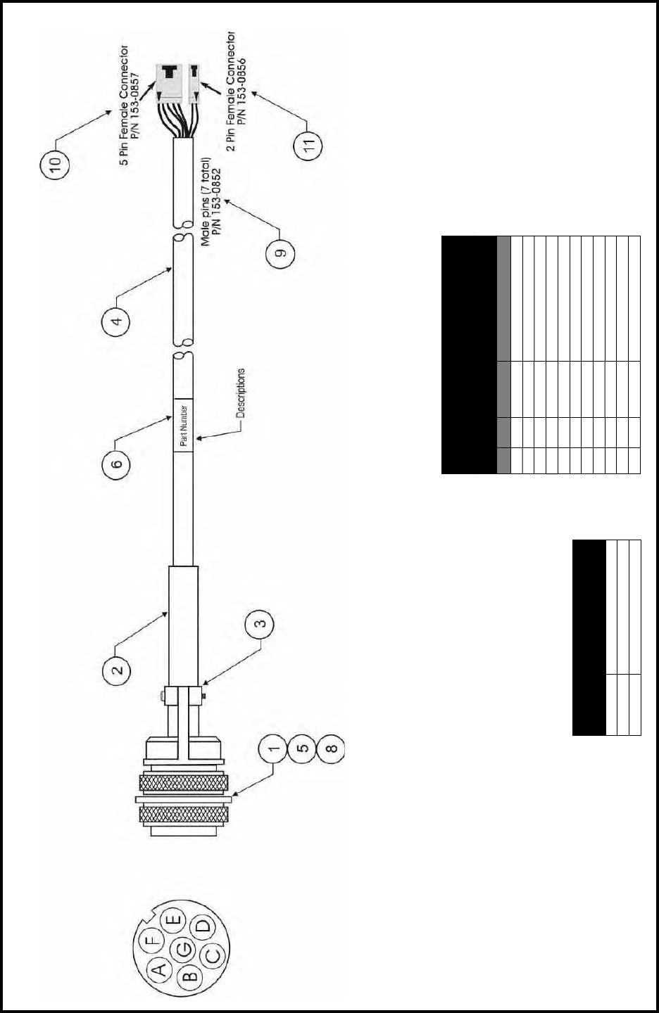
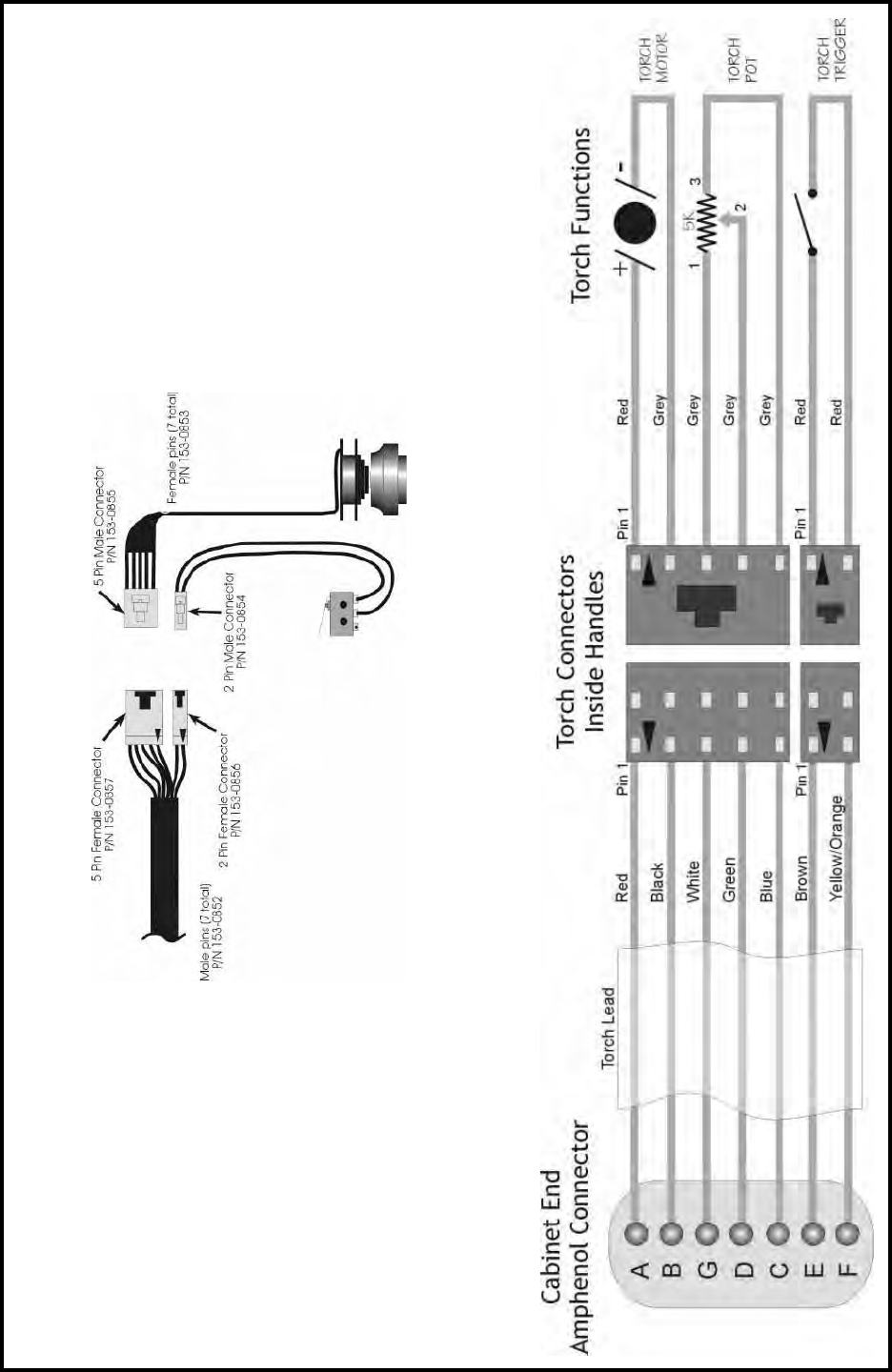
ELECTRICAL CONTROL CABLE
Control Cable
“W” Torches
001-3784, 001-3785, 001-3787,
001-3788, 001-3789, 001-3790, 001-3800
No. Qty. Part No. Description
1 1 153-0322 Connector, 7 Pin, “W”
2 1 301-0004 Boot
3 1 411-0025 Clamp
4 table 844-0070 Cable, & Cond, 22 Ga.
5 0.30ft 739-0004 Tubing, Shrink, Ø1/8
6 1 405-0762 Label, Self Laminate
7 1 411-0159 Clamp, Retaining
8 1 331-0087 Washer, Flat, Neoprene
9 7 153-0852 Male Pins
10 1 153-0857 5 Pin Female Connector
11 1 153-0856 2 Pin Female Connector
Length of cable required
for item #4
25’ 25.5 ft.
50’ 50.5 ft.
75’ 75.5 ft.
Prince® XL - Owner's Manual - Page 26
PRINCE® XL ELECTRICAL

MK Warranty Repair Stations
for MK Products as of April 24, 2003
Please visit our website for up-to-date listing at www.mkproducts.com
ALABAMA
AIRGAS - SOUTH, INC.
Birmingham, AL
205/251-6835
DIXIE WELDING SUPPLY
Attalla, AL
256/538-6157
INDUSTRIAL WELDING SERVICES
Quinton, AL
205/674-3258
KIBRO, INC.
Theodore, AL
251/653-4672
WELDING ENGINEERING SUPPLY CO.
Prichard, AL
334/457-8681
WELDING MACHINE HOSPITAL
Montgomery, AL
334/832-9353
ALASKA
FAIRBANKS AERO SERVICES
Fairbanks, AK
907/479-6666
RNR, INC. dba
Rubey Engine & Electric
Anchorage, AK
907/336-5152
ARIZONA
PRAXAIR DISTRIBUTION, INC.
Phoenix, AZ
602/269-2151
ALLSTATE ELECTRIC MOTOR CO.
Phoenix, AZ
602/233-0500
VERN LEWIS WLDG. SUPPLY
Phoenix, AZ
602/252-0341
ARKANSAS
APPLIED SERVICES, INC.
Benton, AR
501/860-6464
ARKANSAS WELDING IND’L SUPPLY
Hot Springs, AR
501/321-9922
EL DORADO WELDING & IND’L SUPPLY
El Dorado, AR
870/863-4088
CALIFORNIA
ADVANCED WELDER REPAIR
Commerce, CA
323/263-7383
AIRGAS - WEST, INC.
Gardena, CA
310/523-9355
ALL PHASE WELDER REPAIR & CONSULTING
Sacramento, CA
916/331-0595
ARC PRODUCTS
San Diego, CA
619/628-1022
ARCO WELDER REPAIR
Santa Fe Springs, CA
562/921-5240
ARK WELDER REPAIR
Fresno, CA
559/292-4714
CAL-WELD SUPPLY
Fresno, CA
209/445-0131
DELTA-TECH
Sun Valley, CA
818/767-4234
EMCO EAST WELD’R REPAIR
Concord, CA
925/798-4411
FRESNO OXYGEN
Fresno, CA
559/233-6684
INDUSTRIAL ELECTRICAL CO
Modesto, CA
209/527-2800
INDUSTRIAL WELDER REPAIR
LaPuente, CA
626/961-7643
NESCO WELDING SUPPLY
Fontana, CA
909/427-9670
PRAXAIR DISTRIBUTION (ARC RENTS)
Signal Hill, CA
562/989-3212

MK Warranty Repair Stations
for MK Products as of April 24, 2003
Please visit our website for up-to-date listing at www.mkproducts.com
PRAXAIR DISTRIBUTION, INC.
Bakersfi eld, CA
661/321-9922
R. J. KATES
San Diego, CA
619/565-6960
RED-D-ARC, INC.
Carson, CA
310/233-3327
SIMS-ORANGE WELDING SUPPLY
Santa Ana, CA
714/549-9393
SOUTHWEST WELDER REPAIR
Fontana, CA
909/357-1661
SWEINHART ELECTRIC CO., INC.
Long Beach, CA
714/521-9100
CONNETICUT
ABCO WELDING & INDUSTRIAL SUPPLY CO.
Waterford, CT
800/962-0285
TECH AIR
Milford, CT
203/783-1834
COLORADO
AIRGAS - INTERMOUNTAIN, INC.
Colorado Springs, CO
719/473-1947
WELDERS & EQUIP. SVC. & TESTING
Littleton, CO
303/932-8755
WESTERN SLOPE WELDER REPAIR
Grand Junction, CO
970/243-9616
DELAWARE
KEEN COMPRESSED GAS
New Castle, DE
302/594-4555
FLORIDA
A & I SPECIALTIES
Lehigh Acres, FL
941/368-7435
AAA GENERATOR & PUMP
Ft. Myers, FL
941/332-1136
ACTION WELDING SUPPLY
Jacksonville, FL
904/786-2254Miami, FL
305/592-5678
AMVEL CORPORATION
Miami, FL
305/592-5678
ELECTRICAL WELDERS SERVICE
Orlando, FL
407/999-5214
HAUN SYSTEMS REPAIR, INC.
Orlando, FL
407/681-6064
HOLOX
Ocala, FL
352/351-4417
J.K. CIRCUIT TECHNOLOGY
Boynton Beach, FL
561/733-7859
ROPER ELECTRIC MOTOR SERVICE
Panama City, FL
850/769-6643
SMITTY’S WELDER SERVICE
West Palm Beach, FL
561/845-1224
TRI-GAS
Miami, FL
305/592-3180
TRI-STATE SALES & LEASING
Lake City, FL
904/397-3340
TRI-TECH
Sarasota, FL
941/758-3825
V.A. ELECTRICAL MOTORS CENTER
Hialeah, FL
305/825-3327
WELD DIRECT CORPORATION
Jacksonville, FL
904/387-5664
GEORGIA
B&W INDUSTRIAL SERVICES
Augusta, GA
706/738-8722

MK Warranty Repair Stations
for MK Products as of April 24, 2003
Please visit our website for up-to-date listing at www.mkproducts.com
Mc CULLOUGH ELEC. MOTOR SVC.
Atlanta, GA
404/688-5251
HAWAII
DC ELECTRIC, INC.
Aiea, HI
808/483-8900
IDAHO
NORCO
Boise, ID
208/336-1643
ROSSITER ELECTRIC
Idaho Falls, ID
208/529-3665
ILLINOIS
CMS ELECTROMECHANICAL SERVICES, INC.
Galesburg, IL
309/342-4125 – 888/964-3526
FRED ARMS ELECTRIC MOTOR REPAIR
Stone Park, IL
708/343-6262
INDUSTRIAL WELDER REBUILDERS
Alsip, IL
708/371-5688
RELIABLE EQUIPMENT REPAIR
Hamel, IL
618/633-5000
ROCKFORD INDUSTRIAL WELDING SUPPLY
Rockford, IL
815/226-1900
INDIANA
AGA GAS, INC.
Hammond, IN
219/989-9030
AIRGAS-MID AMERICA, INC.
Evansville, IN
800/424-8905
B & H ELECTRIC
Seymour, IN
812/522-5607
COX EQUIPMENT COMPANY
Indianapolis, IN
317/241-8881
EVANSVILLE ARMATURE, INC.
Evansville, IN
812/428-9034
HARRISON ELECTRIC, INC.
Michigan City, IN
219/879-0444
MODERN SUPPLY CO., INC.
Evansville, IN
812/425-9353
PRAXAIR DISTRIBUTION, INC.
Speedway, IN
317/481-4550
SUTTON-GARTEN COMPANY
Indianapolis, IN
317/264-3236
IOWA
AIRGAS NORTH CENTRAL
Des Moines, IA
515/266-1111
CEDAR RAPIDS WELDING SUPPLY
Cedar Rapids, IA
319/365-1466
ELECTRICAL ENGRG. & EQUIPMENT
Des Moines, IA
515/266-8890
SUPERIOR WELDING SUPPLY
Waterloo, IA
319/236-9660
WRIGHT WELDING SUPPLY
Ft. Dodge, IA
515/576-0640
KANSAS
AEROFORM CORPORATION
Coffeyville, KS
620/251-1430
KANOX
Hutchinson, KS
316/665-5551
KENTUCKY
GENERAL WELDING PRODUCTS
Louisville, KY
502/635-5218
RED-D-ARC
Lexington, KY
800/245-3660

MK Warranty Repair Stations
for MK Products as of April 24, 2003
Please visit our website for up-to-date listing at www.mkproducts.com
WELDING EQUIPMENT
Louisville, KY
502/636-0545
LOUISIANA
GT SVCS OF MORGAN CITY
Morgan City, LA
985/385-4135
RED BALL OXYGEN CO.
Shreveport, LA
318/425-3211
WELDERS EQUIPMENT CO.
Broussard, LA
337/837-5701
WELDERS SUPPLY & EQUIP.
Port Allen, LA
225/346-4712
MARYLAND
CCM MECH/ELEC REPAIR SERVICE
Owings, MD
301/855-7508
MASSACHUSETTS
AIMTEK WELDING SUPPLY
Auburn, MA
508/832-5035
MICHIGAN
ANN ARBOR WELDING SUPPLY CO.
Ypsilanti, MI
734/572-0444
APEX WELDING GASES & SUPPLY
Muskegon Heights, MI
616/722-3185
AUTOMATIC WELD
Midland, MI
517/496-9245
GREAT LAKES EQUIPMENT
Clare, MI
517/386-4630
HAMILTON ELECTRIC CO.
Saginaw, MI
517/799-6291
PLYMOUTH WAYNE, INC.
Wixom, MI
248/735-7700
SAGINAW WELDING SUPPLY CO.
Saginaw, MI
517/793-9696
SIMPKINS ELECTRICAL SVC.
Michigan Center, MI
517/764-7766
SOUTHPARK WELDING
Marysville, MI
810/364-6521
WELDING METALS, INC.
Madison Heights, MI
248/585-0480
WESAR COMPANY
Three Rivers, MI
616/483-9125
WILSON WELDING & MEDICAL GASES
Warren, MI
586/751-7400
MINNESOTA
AIRGAS – NORTH CENTRAL
Albert Lea, MN
507/373-2411
CAPITOL CITY WELDING SUPPLY
St. Paul, MN
651/224-4843
CENTRAL McGOWAN
St. Cloud, MN
320/252-5292
MINNEAPOLIS OXYGEN CO.
Minneapolis, MN
612/588-8855
OXYGEN SERVICE CO.
St. Paul, MN
612/644-7273
MISSOURI
CEE-KAY SUPPLY, INC.
St. Louis, MO
324/644-3500
P.G. WALKER
Springfi eld, MO
417/862-1745
ROD’S SERVICE, INC.
St. Louis, MO
314/721-6000
MISSISSIPPI
NORDAN SMITH WELDING SUPPLY
Hattiesburg, MS
601/545-1800

MK Warranty Repair Stations
for MK Products as of April 24, 2003
Please visit our website for up-to-date listing at www.mkproducts.com
3D SUPPLIES, INC.
Jackson, MS
601/353-3330
MONTANA
VALLEY WELDERS SUPPLY
Billings, MT
406/256-3330
NEVADA
SIERRA WELDING SUPPLY CO.
Sparks, NV
775/359-0542
NEW HAMPSHIRE
WELDING SYSTEMS SVC.
Raymond, NH
603/895-4700
NEW JERSEY
INDUSTRIAL ELECTRIC SERVICE CO.
Hawthorne, NJ
973/423-1212
NEW YORK
DELO WELDING SUPPLY
Syracuse, NY
315/478-2188
DYNAMIC WELD’G & REPAIR
Bayshore, NY
631/643-1308
HAUN WELDING SUPPLY
Syracuse, NY
315/463-5241
JACKSON WELDING SUPPLY
Rochester, NY
585/235-2920
NORTH CAROLINA
ADAMS WELDER REPAIR & ELECTRICAL SERVICE,
INC.
Nashville, NC
252/459-1960
HOLOX LTD.
Colfax, NC
336/996-1974
M & L WELDER REPAIR
Asheville, NC
828/250-9353
MACHINE AND WELDING SUPPLY CO.
Dunn, NC
910/892-4016
MACHINE AND WELDING SUPPLY CO.
Greenville, NC
252/752-3089
MACHINE AND WELDING SUPPLY CO.
Raleigh, NC
919/772-9500
MACHINE AND WELDING SUPPLY CO.
Winston-Salem, NC
336/723-9651
NATIONAL WELDERS SUPPLY CO.
High Point, NC
910/882-1110
NATIONAL WELDERS SUPPLY CO.
Charlotte, NC
704/392-7317
OHIO
AGA GASES, INC.
Lima, OH
419/228-2828
ALBRIGHT WELDING SUPPLY
Wooster, OH
330/264-2021
ALL ABOUT SERVICE
Wickliffe, OH
440/516-0303
ARC EQUIPMENT COMPANY
Struthers, OH
333/750-9353
ARC SERVICES, INC.
Toledo, OH
419/478-6204
BELAIR PRODUCTS, INC.
Akron, OH
330/253-3116
BIG RIVER ELECTRIC
Gallipolis, OH
740/446-4360
CnD MACHINE, INC.
Canton, OH
330/478-8811
ELECTRIC WELDER REPAIR
Cuyahoga Heights, OH
216/271-5600
MAINTENANCE UNLTD. & TOOL REPAIR
Cincinnati, OH
513/554-1313

MK Warranty Repair Stations
for MK Products as of April 24, 2003
Please visit our website for up-to-date listing at www.mkproducts.com
O.E. MEYER CO.
Sandusky, OH
419/621-4201
OHIO AIR PRODUCTS
Canton, OH
330/821-2771
RICK’S WELDER REPAIR SERVICE
Eastlake, OH
440/269-1204
S.D. NOLD, INC.
Lisbon, OH
330/424-3134
VALLEY NATIONAL GASES
Cincinnati, OH
513/241-5840
VALLEY NATIONAL GASES
Hilliard, OH
614/771-1311
VALLEY NATIONAL GASES
Lima, OH
419/228-1008
VALLEY NATIONAL GASES
Toledo, OH
419/241-9114
VOLLMER ELECTRIC CO.
Columbus, OH
614/476-8800
WEILER WELDING CO., INC.
Dayton, OH
937/222-8312
WELDINGHOUSE, INC.
Cleveland, OH
216/524-1955
OKLAHOMA
AIRGAS MID-SOUTH
Tulsa, OK
918/582-0885
BILL’S WELDER REPAIR
Oklahoma City, OK
405/232-4799
MUNN SUPPLY
Enid, OK
580/234-4120
OKLAHOMA WELDERS SUPPLY
Madill, OK
580/795-5561
OREGON
ARC SYSTEMS SERVICES
Central Point, OR
541/665-2676
E C COMPANY
dba ELECTRICAL CONSTRUCTION CO.
Portland, OR
800/452-1511
INDUSTRIAL SOURCE
Eugene, OR
541/344-1438
WELDER SERVICE & REPAIR
Redmond, OR
541/548-8711
PENNSYLVANIA
ALLWELD EQUIPMENT REPAIR
Pittsburgh, PA
412/821-8460
BY DESIGN
Columbia, PA
717/681-9494
GEOVIC WELDING SUPPLY
Milton, PA
717/742-9377
J.A. CUNNINGHAM EQUIPMENT, INC.
Philadelphia, PA
215/426-6650
JOSEPH PINTO, JR. EQUIPMENT CO.
E. Lansdowne, PA
610/259-4100
POWER SOURCE REPAIR CO., INC.
Collingdale, PA
610/532-6460
VALLEY NATIONAL GASES
Pittsburgh, PA
412/281-1835
SOUTH CAROLINA
CAROLINA WELDER SERVICE
Lake City, SC
843/687-0413
TENNESSEE
INDUSTRIAL MACHINE REPAIRS
Rogersville, TN
423/272-8199
NATIONAL RENTAL & REPAIR
Knoxville, TN
423/584-6390

MK Warranty Repair Stations
for MK Products as of April 24, 2003
Please visit our website for up-to-date listing at www.mkproducts.com
NEXAIR
Memphis, TN
901/523-6821
QUALITY WELD’G EQUIPMENT
Nashville, TN
615/726-5282
TRAMCO
Bristol, TN
423/968-4499
TEXAS
AIRGAS - SOUTHWEST, INC.
Austin, TX
512/835-0202
AIRGAS - SOUTHWEST, INC.
Houston, TX
713/462-8027
DENISON OXYGEN
Denison, TX
903/465-3369
FT. WORTH WELDERS SUPPLY, INC.
Fort Worth, TX
817/332-8696
GPC SERVICES, INC.
San Angelo, TX
915/655-4545
LEKTROTECH, INC.
Greenville, TX
903/454-7146
RITE-WELD SUPPLY, INC
Fort Worth, TX
817/626-8237
TexAir WELDING SUPPLY
Longview, TX
903/238-9353
WELDING MACHINE & TORCH REPAIR
San Antonio, TX
210/680-8390
UTAH
ARC SERVICES, LLC
West Valley City, UT
801/975-1121
C.W. SILVER INDUSTRIAL SERVICE
Salt Lake City, UT
801/531-8888
W.J. WELDING EQUIPMENT REPAIR, INC.
N. Clarendon, VT
802/775-7422
VIRGINIA
AIR PRODUCTS & CHEMICALS, INC.
Bristol, VA
540/669-3161
ARC WELDERS, INC.
Ashland, VA
804/798-1818
ARCET EQUIPMENT CO.
Hampton, VA
757/728-9353
N.W. MARTIN CO.
Springfi eld, VA
703/644-0120
NORFOLK WELDERS SUPPLY
Norfolk, VA
804/622-6571
WASHINGTON
AIRGAS - NORPAC, INC.
Tacoma, WA
253/473-2282
AIRGAS – NORPAC, INC.
Vancouver, WA
360/574-5311
A-L WELDING PRODUCTS
Tukwila, WA
425/228-2218
AMERICAN EQUIPMENT SERVICES
Kent, WA
253/395-9947
HARRIS ELECTRIC, INC.
Seattle, WA
206/782-6668
OXARC, INC.
Spokane, WA
509/535-7794
PACIFIC WELDING SUPPLIES
Tacoma, WA
253/572-5302
PRECISION WELDER & ENGINE REPAIR
Seattle, WA
206/382-6227

MK Warranty Repair Stations
for MK Products as of April 24, 2003
Please visit our website for up-to-date listing at www.mkproducts.com
WEST VIRGINIA
CARDINAL SALES & SERVICE, INC.
Clarksburg, WV
304/622-7590
WILLARD C. STARCHER
Spencer, WV
304/927-2520
WISCONSIN
INTERSTATE WELDING SALES CORP.
Appleton, WI
920/734-7173
MOSINEE MACHINE & ELECTRIC
Mosinee, WI
715/693-0858
PRAXAIR DISTRIBUTION, INC.
Brookfi eld, WI
414/938-6365
VALLEY NATIONAL GASES
Milwaukee, WI
414/281-9540
WELDER REPAIR & SERVICE, INC.
Fredonia, WI
262/692-3068
CANADA
A&A WELDER SERVICES LTD.
Saskatoon, Saskatchewan
306/934-1601
ARC & GENERATOR REPAIR
Garson, Ontario
705/525-2141
B. HARRIS WELDING SVCS. LTD.
Dartmouth, Nova Scotia
902/468-6255
BARRY HAMEL EQUIPMENT LTD.
Coquitlam, B.C.
604/945-9313
D-TECH WELD SERVICES
Regina, Saskatchewan
306/586-9353
ELECTRO-MÉCANIK, INC.
Sainte-Foy, Quebec
418/683-1724
GPR INDUSTRIES 1994 LTD.
Grande Prairie, Alberta
780/532-5900
HYPERDYNAMICS TECHNOLOGIES LTD.
Pickering, Ontario
905/683-9938
INDUSTRIAL ELECTRONIC SERVICES
Calgary, Alberta
403/279-3432
LADEL LTD.
Quebec
819/376-6577
LeBLANC ELECTRO-TECH, INC.
Boucherville, Quebec
450/449-5244
M.R.T. REPAIR CENTER, INC.
Montreal, Quebec
514/648-0800
OZARK ELECTRICAL MARINE LTD.
St. Johns, Newfoundland
709/726-4554
PEEL ENGINES
Mississauga, Ontario
905/670-1535
PROMOTECH ÉLECTRIQUE, INC.
Fleurimont, Quebec
819/822-2111
WELDERS SUPPLY
Winnipeg, Manitoba
204/772-9476
WELDERTECH
Calgary, Alberta
403/279-3432
WELDTEC
B.C.
604/545-3886
CHINA
PHT Group Company
Beijing, China
86-10-6858 8395

THIS PAGE INTENTIONALLY BLANK

DATE: February 1, 2003
MK Products, Inc.
16882 Armstrong Ave.
Irvine, CA 92606
Tel (949)863-1234
Fax (949)474-1428
Sales and Service through Subsidiaries and Distributors Worldwide
Cleveland, Ohio 44117-1199 U.S.A. TEL: 216.481.8100 FAX: 216.486.1751 WEB SITE: www.lincolnelectric.com
World’s Leader in Welding and Cutting Prodcuts
LINCOLN
ELECTRIC
®
Copyright © 2003 Lincoln Global Inc.
3 YEAR
LIMITED WARRANTY
Effective February 1, 2003
This warranty supersedes all previous MK Products warranties and is
exclusive, with no other guarantees or warranties expressed or implied.
LIMITED WARRANTY - MK Products,Inc.,Irvine,California
warrants that all new and unused equipment furnished by MK
Products is free from defects in workmanship and material as
of the time and place of delivery by MK Products. No warranty
is made by MK Products with respect to trade accessories or
other items manufactured by others. Such trade accessories and
other items are sold subject to the warranties of their respective
manufacturers, if any.
MK Products’ warranty does not apply to components having
normal useful life of less than one (1) year, such as relay points,
wire conduit, tungsten, and welding torch parts that come in
contact with the welding wire, including gas cups, gas cup insula-
tors, and contact tips where failure does not result from defect
in workmanship or material.
MK Products’ shall, exclusively remedy the limited warranty or
any duties with respect to the quality of goods, based upon
the following options:
(1) repair
(2) replacement
(3) where authorized in writing by MK Products, the reasonable
cost of repair or replacement at our Irvine, California plant; or
(4) payment of or credit for the purchase price (less reasonable
depreciation based upon actual use) upon return of the goods at
customer’s risk and expense. Upon receipt of notice of apparent
defect or failure, MK Products shall instruct the claimant on the
warranty claim procedures to be followed.
As a matter of general policy only, MK Products may honor an
original user’s warranty claims on warranted equipment in the
event of failure resulting from a defect within the following periods
from the date of delivery of equipment to the original user:
1. Torches, Weldheads & Water Recirculators .....1 year
2. All Other Equipment ....................................... 3 years
3. Repairs ......................................................... 90 days
Classifi cation of any item into the foregoing categories shall be
at the sole discretion of MK Products. Notifi cation of any failure
must be made in writing within 30 days of such failure.
A copy of the invoice showing the date of sale must accompany
products returned for warranty repair or replacement.
All equipment returned to MK Products for service must be
properly packaged to guard against damage from shipping.
MK Products will not be responsible for any damages resulting
from shipping.
Normal surface transportation charges (both ways) for products
returned for warranty repair or replacement will be borne by
MK Products, except for products sold to foreign markets.
ANY EXPRESS WARRANTY NOT PROVIDED HEREIN AND ANY
IMPLIED WARRANTY, GUARANTY, OR REPRESENTATION AS
TO PERFORMANCE, AND ANY REMEDY FOR BREACH OF
CONTRACT WHICH, BUT FOR THIS PROVISION, MIGHT
ARISE BY IMPLICATION, OPERATION OF LAW, CUSTOM OF
TRADE, OR COURSE OF DEALING, INCLUDING ANY IMPLIED
WARRANTY OF MERCHANTABILITY OR OF FITNESS FOR
PARTICULAR PURPOSE, WITH RESPECT TO ANY AND ALL
EQUIPMENT FURNISHED BY MK PRODUCTS, IS EXCLUDED
AND DISCLAIMED BY MK PRODUCTS.
EXCEPT AS EXPRESSLY PROVIDED BY MK PRODUCTS IN
WRITING, MK PRODUCTS ARE INTENDED FOR ULTIMATE
PURCHASE BY COMMERCIAL/INDUSTRIAL USERS AND FOR
OPERATION BY PERSONS TRAINED AND EXPERIENCED IN
THE USE AND MAINTENANCE OF WELDING EQUIPMENT AND
NOT FOR CONSUMERS OR CONSUMER USE. MK PRODUCTS
WARRANTIES DO NOT EXTEND TO, AND NO RE-SELLER IS
AUTHORIZED TO EXTEND MK PRODUCTS’ WARRANTIES TO
ANY CONSUMER.
USE OF OTHER THAN
GENUINE
MK PRODUCTS’
CONSUMABLES, PARTS, AND ACCESSORIES MAY INVALIDATE
YOUR PRODUCT WARRANTY.
