Lincoln Electric Ranger 9 Svm 110 A Users Manual Svm110a
SVM 110-A to the manual d398d9eb-ece8-44a9-a757-e52441a35eb8
2015-02-09
: Lincoln-Electric Lincoln-Electric-Ranger-9-Svm-110-A-Users-Manual-574457 lincoln-electric-ranger-9-svm-110-a-users-manual-574457 lincoln-electric pdf
Open the PDF directly: View PDF ![]() .
.
Page Count: 134 [warning: Documents this large are best viewed by clicking the View PDF Link!]
- Master TOC
- Safety
- Section A Installation
- Section B Operation
- Section C Accessories
- Section D Maintenance
- Section E Theory of Operation
- Section F Troubleshooting & Repair
- Symptoms
- Major physical or electrical damage is evident.
- No weld output and no auxiliary power. Engine operates normally.
- No weld output, the auxiliary power (230-115VAC) is operating normally. Engine operates normally.
- No auxiliary power at receptacles – welding output is normal – engine runs normally.
- Machine has low welding output and low auxiliary output.
- No DC welding output. AC welding output and auxiliary power are normal.
- No AC welding output. DC welding output and auxiliary power are normal.
- No constant voltage (CV) welding output. Constant current (CC) and the auxiliary power are operating normally.
- The constant voltage (CV) welding output is low or unstable. Constant current (CC) and the auxiliary
- Engine will not idle down to low speed. Machine has normal weld output and auxiliary power.
- Engine will not go to high idle when attempting to weld. Welding output is normal when Idler switch is in "HIGH" position. ......
- Engine will not go to high idle when attempting to weld or when the auxiliary power is loaded. Welding output and auxiliary......
- Engine will not crank or cranks very slowly.
- The engine shuts off or will not start.
- The engine does not develop full power.
- The welding arc is “ cold.” The engine runs normally (3700 RPM no load). The auxiliary power is functioning normally.
- Output control on welder not functioning.
- Remote output control not functioning.
- The wire feeder does not work when connected to the welder amphenol.
- The contactor does not pull in when scratch starting when the engine goes to high idle.
- The output contactor does not pull in when using a wire feeder with a control cable connected to the RANGER 9 amphenol.
- The output contactor does NOT drop out.
- Section G Electrical Diagrams
SVM 110-A
January, 1996
Safety Depends on You
Lincoln arc welding and cutting
equipment is designed and built
with safety in mind. However,
your overall safety can be
increased by proper installation .
. . and thoughtful operation on
your part. DO NOT INSTALL,
OPERATE OR REPAIR THIS
EQUIPMENT WITHOUT READ-
ING THIS MANUAL AND THE
SAFETY PRECAUTIONS CON-
TAINED THROUGHOUT. And,
most importantly, think before
you act and be careful.
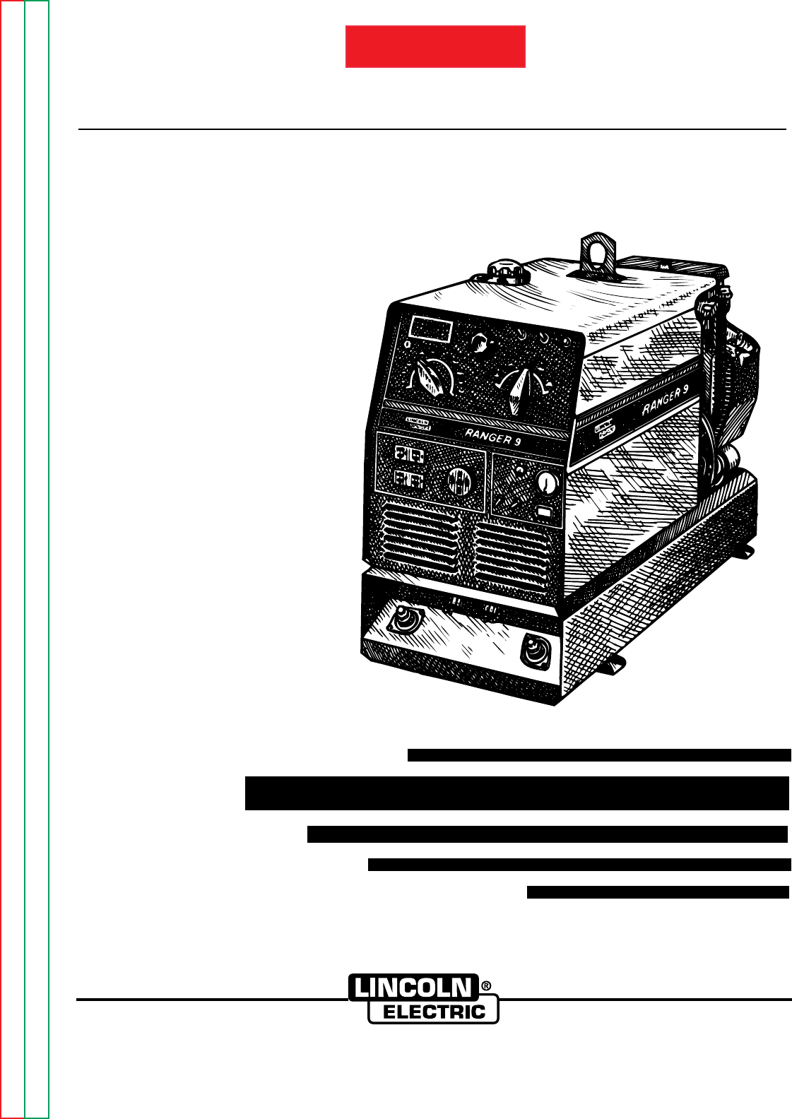
SERVICE MANUAL
World’s Leader in Welding and Cutting Products Premier Manufacturer of Industrial Motors
Sales and Service through subsidiaries and Distributors Worldwide
22801 St. Clair Ave. Cleveland, Ohio 44117-1199 U.S.A. Tel. (216) 481-8100
For use with machine code numbers 9975 and 9976
RANGER 9
TM
RETURN TO MAIN INDEX
Return to Master TOC Return to Master TOC Return to Master TOC Return to Master TOC
View Safety Info View Safety Info View Safety Info View Safety Info
SAFETY
i i
FOR ENGINE
powered equipment.
1.a. Turn the engine off before troubleshooting and maintenance
work unless the maintenance work requires it to be running.
____________________________________________________
1.b.Operate engines in open, well-ventilated
areas or vent the engine exhaust fumes
outdoors.
____________________________________________________
1.c. Do not add the fuel near an open flame weld-
ing arc or when the engine is running. Stop
the engine and allow it to cool before refuel-
ing to prevent spilled fuel from vaporizing on
contact with hot engine parts and igniting. Do
not spill fuel when filling tank. If fuel is spilled,
wipe it up and do not start engine until fumes
have been eliminated.
____________________________________________________
1.d. Keep all equipment safety guards, covers
and devices in position and in good
repair.Keep hands, hair, clothing and tools
away from V-belts, gears, fans and all other
moving parts when starting, operating or
repairing equipment.
____________________________________________________
1.e. In some cases it may be necessary to remove safety
guards to perform required maintenance. Remove
guards only when necessary and replace them when the
maintenance requiring their removal is complete.
Always use the greatest care when working near moving
parts.
___________________________________________________
1.f. Do not put your hands near the engine fan. Do not attempt to
override the governor or idler by pushing on the throttle con-
trol rods while the engine is running.
___________________________________________________
1.g. To prevent accidentally starting gasoline engines while
turning the engine or welding generator during maintenance
work, disconnect the spark plug wires, distributor cap or
magneto wire as appropriate.
ARC WELDING CAN BE HAZARDOUS. PROTECT YOURSELF AND OTHERS FROM POSSIBLE SERIOUS INJURY OR DEATH.
KEEP CHILDREN AWAY. PACEMAKER WEARERS SHOULD CONSULT WITH THEIR DOCTOR BEFORE OPERATING.
Read and understand the following safety highlights. For additional safety information, it is strongly recommended that you
purchase a copy of “Safety in Welding & Cutting - ANSI Standard Z49.1” from the American Welding Society, P.O. Box 351040,
Miami, Florida 33135 or CSA Standard W117.2-1974. A Free copy of “Arc Welding Safety” booklet E205 is available from the
Lincoln Electric Company, 22801 St. Clair Avenue, Cleveland, Ohio 44117-1199.
BE SURE THAT ALL INSTALLATION, OPERATION, MAINTENANCE AND REPAIR PROCEDURES ARE
PERFORMED ONLY BY QUALIFIED INDIVIDUALS.
WARNING
Mar ‘95
ELECTRIC AND
MAGNETIC FIELDS
may be dangerous
2.a. Electric current flowing through any conductor causes
localized Electric and Magnetic Fields (EMF). Welding
current creates EMF fields around welding cables and
welding machines
2.b. EMF fields may interfere with some pacemakers, and
welders having a pacemaker should consult their physician
before welding.
2.c. Exposure to EMF fields in welding may have other health
effects which are now not known.
2.d. All welders should use the following procedures in order to
minimize exposure to EMF fields from the welding circuit:
2.d.1.
Route the electrode and work cables together - Secure
them with tape when possible.
2.d.2. Never coil the electrode lead around your body.
2.d.3. Do not place your body between the electrode and
work cables. If the electrode cable is on your right
side, the work cable should also be on your right side.
2.d.4. Connect the work cable to the workpiece as close as
possible to the area being welded.
2.d.5. Do not work next to welding power source.
1.h. To avoid scalding, do not remove the
radiator pressure cap when the engine is
hot.
CALIFORNIA PROPOSITION 65 WARNINGS
Diesel engine exhaust and some of its constituents
are known to the State of California to cause can-
cer, birth defects, and other reproductive harm.
The engine exhaust from this product contains
chemicals known to the State of California to cause
cancer, birth defects, or other reproductive harm.
The Above For Diesel Engines The Above For Gasoline Engines
Return to Master TOC Return to Master TOC Return to Master TOC Return to Master TOC
SAFETY
ii ii
ARC RAYS can burn.
4.a. Use a shield with the proper filter and cover
plates to protect your eyes from sparks and
the rays of the arc when welding or observing
open arc welding. Headshield and filter lens
should conform to ANSI Z87. I standards.
4.b. Use suitable clothing made from durable flame-resistant
material to protect your skin and that of your helpers from
the arc rays.
4.c. Protect other nearby personnel with suitable, non-flammable
screening and/or warn them not to watch the arc nor expose
themselves to the arc rays or to hot spatter or metal.
ELECTRIC SHOCK can kill.
3.a. The electrode and work (or ground) circuits
are electrically “hot” when the welder is on.
Do not touch these “hot” parts with your bare
skin or wet clothing. Wear dry, hole-free
gloves to insulate hands.
3.b. Insulate yourself from work and ground using dry insulation.
Make certain the insulation is large enough to cover your full
area of physical contact with work and ground.
In addition to the normal safety precautions, if welding
must be performed under electrically hazardous
conditions (in damp locations or while wearing wet
clothing; on metal structures such as floors, gratings or
scaffolds; when in cramped positions such as sitting,
kneeling or lying, if there is a high risk of unavoidable or
accidental contact with the workpiece or ground) use
the following equipment:
• Semiautomatic DC Constant Voltage (Wire) Welder.
• DC Manual (Stick) Welder.
• AC Welder with Reduced Voltage Control.
3.c. In semiautomatic or automatic wire welding, the electrode,
electrode reel, welding head, nozzle or semiautomatic
welding gun are also electrically “hot”.
3.d. Always be sure the work cable makes a good electrical
connection with the metal being welded. The connection
should be as close as possible to the area being welded.
3.e. Ground the work or metal to be welded to a good electrical
(earth) ground.
3.f.
Maintain the electrode holder, work clamp, welding cable and
welding machine in good, safe operating condition. Replace
damaged insulation.
3.g. Never dip the electrode in water for cooling.
3.h. Never simultaneously touch electrically “hot” parts of
electrode holders connected to two welders because voltage
between the two can be the total of the open circuit voltage
of both welders.
3.i. When working above floor level, use a safety belt to protect
yourself from a fall should you get a shock.
3.j. Also see Items 6.c. and 8.
FUMES AND GASES
can be dangerous.
5.a. Welding may produce fumes and gases
hazardous to health. Avoid breathing these
fumes and gases.When welding, keep
your head out of the fume. Use enough
ventilation and/or exhaust at the arc to keep
fumes and gases away from the breathing zone. When
welding with electrodes which require special
ventilation such as stainless or hard facing (see
instructions on container or MSDS) or on lead or
cadmium plated steel and other metals or coatings
which produce highly toxic fumes, keep exposure as
low as possible and below Threshold Limit Values (TLV)
using local exhaust or mechanical ventilation. In
confined spaces or in some circumstances, outdoors, a
respirator may be required. Additional precautions are
also required when welding on galvanized steel.
5.b.
Do not weld in locations near chlorinated hydrocarbon
vapors
coming from degreasing, cleaning or spraying operations.
The heat and rays of the arc can react with solvent vapors
to
form phosgene, a highly toxic gas, and other irritating
products.
5.c. Shielding gases used for arc welding can displace air and
cause injury or death. Always use enough ventilation,
especially in confined areas, to insure breathing air is safe.
5.d. Read and understand the manufacturer’s instructions for this
equipment and the consumables to be used, including the
material safety data sheet (MSDS) and follow your
employer’s safety practices. MSDS forms are available from
your welding distributor or from the manufacturer.
5.e. Also see item 1.b. Mar ‘95
Return to Master TOC Return to Master TOC Return to Master TOC Return to Master TOC
SAFETY
iii iii
FOR ELECTRICALLY
powered equipment.
8.a. Turn off input power using the disconnect
switch at the fuse box before working on
the equipment.
8.b. Install equipment in accordance with the U.S. National
Electrical Code, all local codes and the manufacturer’s
recommendations.
8.c. Ground the equipment in accordance with the U.S. National
Electrical Code and the manufacturer’s recommendations.
CYLINDER may explode
if damaged.
7.a. Use only compressed gas cylinders
containing the correct shielding gas for the
process used and properly operating
regulators designed for the gas and
pressure used. All hoses, fittings, etc. should be suitable for
the application and maintained in good condition.
7.b. Always keep cylinders in an upright position securely
chained to an undercarriage or fixed support.
7.c. Cylinders should be located:
•Away from areas where they may be struck or subjected to
physical damage.
•A safe distance from arc welding or cutting operations and
any other source of heat, sparks, or flame.
7.d. Never allow the electrode, electrode holder or any other
electrically “hot” parts to touch a cylinder.
7.e. Keep your head and face away from the cylinder valve outlet
when opening the cylinder valve.
7.f. Valve protection caps should always be in place and hand
tight except when the cylinder is in use or connected for
use.
7.g. Read and follow the instructions on compressed gas
cylinders, associated equipment, and CGA publication P-l,
“Precautions for Safe Handling of Compressed Gases in
Cylinders,” available from the Compressed Gas Association
1235 Jefferson Davis Highway, Arlington, VA 22202.
Mar ‘95
WELDING SPARKS can
cause fire or explosion.
6.a.
Remove fire hazards from the welding area.
If this is not possible, cover them to prevent
the welding sparks from starting a fire.
Remember that welding sparks and hot
materials from welding can easily go through small cracks
and openings to adjacent areas. Avoid welding near
hydraulic lines. Have a fire extinguisher readily available.
6.b. Where compressed gases are to be used at the job site,
special precautions should be used to prevent hazardous
situations. Refer to “Safety in Welding and Cutting” (ANSI
Standard Z49.1) and the operating information for the
equipment being used.
6.c. When not welding, make certain no part of the electrode
circuit is touching the work or ground. Accidental contact can
cause overheating and create a fire hazard.
6.d. Do not heat, cut or weld tanks, drums or containers until the
proper steps have been taken to insure that such procedures
will not cause flammable or toxic vapors from substances
inside. They can cause an explosion even
though
they have
been “cleaned”. For information, purchase “Recommended
Safe Practices for the
Preparation
for Welding and Cutting of
Containers and Piping That Have Held Hazardous
Substances”, AWS F4.1 from the American Welding Society
(see address above).
6.e. Vent hollow castings or containers before heating, cutting or
welding. They may explode.
6.f.
Sparks and spatter are thrown from the welding arc. Wear oil
free protective garments such as leather gloves, heavy shirt,
cuffless trousers, high shoes and a cap over your hair. Wear
ear plugs when welding out of position or in confined places.
Always wear safety glasses with side shields when in a
welding area.
6.g. Connect the work cable to the work as close to the welding
area as practical. Work cables connected to the building
framework or other locations away from the welding area
increase the possibility of the welding current passing
through lifting chains, crane cables or other alternate circuits.
This can create fire hazards or overheat lifting chains or
cables until they fail.
6.h. Also see item 1.c.
Return to Master TOC Return to Master TOC Return to Master TOC Return to Master TOC

SAFETY
iv iv
PRÉCAUTIONS DE SÛRETÉ
Pour votre propre protection lire et observer toutes les instructions
et les précautions de sûreté specifiques qui parraissent dans ce
manuel aussi bien que les précautions de sûreté générales suiv-
antes:
Sûreté Pour Soudage A L’Arc
1. Protegez-vous contre la secousse électrique:
a. Les circuits à l’électrode et à la piéce sont sous tension
quand la machine à souder est en marche. Eviter toujours
tout contact entre les parties sous tension et la peau nue
ou les vétements mouillés. Porter des gants secs et sans
trous pour isoler les mains.
b. Faire trés attention de bien s’isoler de la masse quand on
soude dans des endroits humides, ou sur un plancher met-
allique ou des grilles metalliques, principalement dans
les positions assis ou couché pour lesquelles une grande
partie du corps peut être en contact avec la masse.
c. Maintenir le porte-électrode, la pince de masse, le câble de
soudage et la machine à souder en bon et sûr état defonc-
tionnement.
d.Ne jamais plonger le porte-électrode dans l’eau pour le
refroidir.
e. Ne jamais toucher simultanément les parties sous tension
des porte-électrodes connectés à deux machines à soud-
er parce que la tension entre les deux pinces peut être le
total de la tension à vide des deux machines.
f. Si on utilise la machine à souder comme une source de
courant pour soudage semi-automatique, ces precautions
pour le porte-électrode s’applicuent aussi au pistolet de
soudage.
2. Dans le cas de travail au dessus du niveau du sol, se protéger
contre les chutes dans le cas ou on recoit un choc. Ne jamais
enrouler le câble-électrode autour de n’importe quelle partie
du corps.
3. Un coup d’arc peut être plus sévère qu’un coup de soliel,
donc:
a. Utiliser un bon masque avec un verre filtrant approprié
ainsi qu’un verre blanc afin de se protéger les yeux du ray-
onnement de l’arc et des projections quand on soude ou
quand on regarde l’arc.
b. Porter des vêtements convenables afin de protéger la
peau de soudeur et des aides contre le rayonnement de
l‘arc.
c. Protéger l’autre personnel travaillant à proximité au
soudage à l’aide d’écrans appropriés et non-inflammables.
4. Des gouttes de laitier en fusion sont émises de l’arc de
soudage. Se protéger avec des vêtements de protection libres
de l’huile, tels que les gants en cuir, chemise épaisse, pan-
talons sans revers, et chaussures montantes.
5. Toujours porter des lunettes de sécurité dans la zone de
soudage. Utiliser des lunettes avec écrans lateraux dans les
zones où l’on pique le laitier.
6. Eloigner les matériaux inflammables ou les recouvrir afin de
prévenir tout risque d’incendie dû aux étincelles.
7. Quand on ne soude pas, poser la pince à une endroit isolé de
la masse. Un court-circuit accidental peut provoquer un
échauffement et un risque d’incendie.
8. S’assurer que la masse est connectée le plus prés possible de
la zone de travail qu’il est pratique de le faire. Si on place la
masse sur la charpente de la construction ou d’autres endroits
éloignés de la zone de travail, on augmente le risque de voir
passer le courant de soudage par les chaines de levage,
câbles de grue, ou autres circuits. Cela peut provoquer des
risques d’incendie ou d’echauffement des chaines et des
câbles jusqu’à ce qu’ils se rompent.
9. Assurer une ventilation suffisante dans la zone de soudage.
Ceci est particuliérement important pour le soudage de tôles
galvanisées plombées, ou cadmiées ou tout autre métal qui
produit des fumeés toxiques.
10. Ne pas souder en présence de vapeurs de chlore provenant
d’opérations de dégraissage, nettoyage ou pistolage. La
chaleur ou les rayons de l’arc peuvent réagir avec les vapeurs
du solvant pour produire du phosgéne (gas fortement toxique)
ou autres produits irritants.
11. Pour obtenir de plus amples renseignements sur la sûreté, voir
le code “Code for safety in welding and cutting” CSA Standard
W 117.2-1974.
PRÉCAUTIONS DE SÛRETÉ POUR
LES MACHINES À SOUDER À
TRANSFORMATEUR ET À
REDRESSEUR
1. Relier à la terre le chassis du poste conformement au code de
l’électricité et aux recommendations du fabricant. Le dispositif
de montage ou la piece à souder doit être branché à une
bonne mise à la terre.
2. Autant que possible, I’installation et l’entretien du poste seront
effectués par un électricien qualifié.
3. Avant de faires des travaux à l’interieur de poste, la debranch-
er à l’interrupteur à la boite de fusibles.
4. Garder tous les couvercles et dispositifs de sûreté à leur
place.
Mar. ‘93
Return to Master TOC Return to Master TOC Return to Master TOC Return to Master TOC

v v
RANGER 9 RANGER 9
Page
Safety.................................................................................................................................................i-iv
Installation.............................................................................................................................Section A
Installation Section Table of Contents........................................................................................A-1
Technical Specifications.............................................................................................................A-2
Safety Precautions......................................................................................................................A-3
Location and Ventilation.............................................................................................................A-3
Pre-operation Engine Service.....................................................................................................A-4
Electrical Output Connections....................................................................................................A-5
Operation...............................................................................................................................Section B
Safety Instructions......................................................................................................................B-2
General Description....................................................................................................................B-2
Recommended Applications......................................................................................................B-3
Operational Features and Controls............................................................................................B-3
Design Features and Advantages...............................................................................................B-3
Welding Capability......................................................................................................................B-4
Limitations.................................................................................................................................B-4
Controls and Settings.................................................................................................................B-4
Engine Operation........................................................................................................................B-7
Welding Operation....................................................................................................................B-10
Summary of Welding Processes...............................................................................................B-13
Auxiliary Power.........................................................................................................................B-14
Accessories...........................................................................................................................Section C
Maintenance.........................................................................................................................Section D
Safety Precautions......................................................................................................................D-2
Routine and Periodic Maintenance............................................................................................D-2
Major Component Locations......................................................................................................D-9
Theory of Operation.............................................................................................................Section E
Troubleshooting and Repair.................................................................................................Section F
Electrical Diagrams..............................................................................................................Section G
Parts Manual................................................................................................................................P-230
RETURNTOMAIN INDEX
MASTER TABLE OF CONTENTS FOR ALL SECTIONS

TABLE OF CONTENTS
- INSTALLATION SECTION -
Section A-1 Section A-1
RANGER 9 RANGER 9
Installation
Technical Specifications .............................................................................................................A-2
Safety Precautions......................................................................................................................A-3
Location and Ventilation .............................................................................................................A-3
Storing .................................................................................................................................A-3
Stacking................................................................................................................................A-4
Tilting .................................................................................................................................A-4
Lifting .................................................................................................................................A-4
High Altitude Operation........................................................................................................A-4
Pre-operation Engine Service.....................................................................................................A-4
Oil ........................................................................................................................................A-4
Fuel.......................................................................................................................................A-4
Battery Connections.............................................................................................................A-4
Muffler Relocation ................................................................................................................A-5
Spark Arrester ......................................................................................................................A-5
Electrical Output Connections....................................................................................................A-5
Welding Cable Connections.................................................................................................A-6
Cable Size and Length............................................................................................A-6
Cable Installation.....................................................................................................A-6
Machine Grounding..............................................................................................................A-6
Auxiliary Power Receptacles, Plugs, and Hand-Held Equipment .......................................A-7
Circuit Breakers....................................................................................................................A-7
Premises Wiring....................................................................................................................A-7
Return to Master TOC Return to Master TOC Return to Master TOC Return to Master TOC
Return to Section TOC Return to Section TOC Return to Section TOC Return to Section TOC
Return to Master TOC Return to Master TOC Return to Master TOC Return to Master TOC
INSTALLATION
A-2 A-2
RANGER 9 RANGER 9
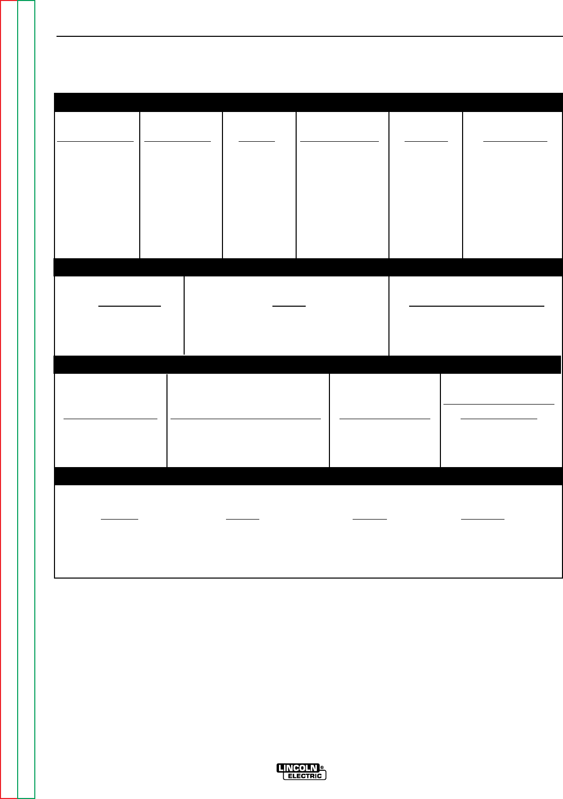
TECHNICAL SPECIFICATIONS - RANGER 9
INPUT - GASOLINE ENGINE
Manufacturer Description Speed Displacement Ignition Capacities
Onan 2 cyl., 3500 RPM 47.7 cu. in. Electric Fuel: 9 gal. (34 l)
P218®4 cycle Full load (782 cc)
air-cooled Manual Oil: 1.8 qt. (1.7 l)
gasoline 3700 RPM choke
18 HP @ High idle
3600 RPM 2200 RPM
Low idle
RATED OUTPUT - WELDER
Duty Cycle Amps Volts at Rated Amperes
100% Duty Cycle 250 AC Constant Current 25
100% Duty Cycle 250 DC Constant Current 25
100% Duty Cycle 250 DC Constant Voltage 25
OUTPUT - WELDER AND GENERATOR
Auxiliary Power for
Welding Ranges Max. Open Circuit Voltage Auxiliary Power Wire Feeders
40 - 250 Amps 80 Volts RMS 9000 Continuous Watts 42V, 60 Hz, 8 Amps
@ 3700 RPM 80 Amps @ 115 V
40 Amps @ 230 V 115V, 60 Hz, 8 Amps
PHYSICAL DIMENSIONS
Height Width Depth Weight
With Onan Engine:
30.3 in. 19.2 in. 42.3 in. 562 lb.
770 mm 485 mm 1074 mm 255 kg
Read this entire installation section before you
start installation.
SAFETY PRECAUTIONS
Do not attempt to use this equipment until you have
thoroughly read all the operation and maintenance
manuals supplied with your machine. They include
important safety precautions; detailed engine starting,
operating, and maintenance instructions; and parts
lists.
ELECTRIC SHOCK can kill.
• Do not touch electrically live
parts or electrodes with your
skin or wet clothing.
• Insulate yourself from the work
and ground.
• Always wear dry insulating
gloves.
ENGINE EXHAUST can kill.
• Use in open, well ventilated
areas or vent exhaust to the out-
side.
• Do not stack anything on or near
the engine.
MOVING PARTS can injure.
• Do not operate this equipment
with any of its doors open or
guards off.
• Stop the engine before servicing
it.
• Keep away from moving parts.
Only qualified personnel should install, use, or ser-
vice this equipment.
LOCATION AND VENTILATION
Whenever you use the RANGER 9, be sure that clean
cooling air can flow through the machine’s gasoline
engine and the machine case. Avoid dusty, dirty
areas. Also, keep the machine away from heat
sources. Do not place the back end of the generator
anywhere near hot engine exhaust from another
machine. And of course, make sure that engine
exhaust is ventilated to an open, outside area.
The RANGER 9 may be used outdoors. Do not set the
machine in puddles or otherwise submerge it in water.
Such practices pose safety hazards and cause
improper operation and corrosion of parts.
Always operate the RANGER 9 with the case roof on
and all machine components completely assembled.
This will protect you from the dangers of moving parts,
hot metal surfaces, and live electrical devices.
Damage to the fuel tank may cause fire or explosion.
Do not drill holes in the RANGER 9 base or weld to the
RANGER 9 base.
STORING
1. Store the machine in a cool, dry place when it’s
not in use. Protect it from dust and dirt. Keep it
where it can’t be accidentally damaged from con-
struction activities, moving vehicles, and other
hazards.
2. If you will be storing the machine for over 30 days,
you should drain the fuel to protect fuel system
and carburetor parts from gum deposits. Empty
all fuel from the tank and run the engine until it
stops from lack of fuel. If you prefer, you can treat
the gasoline with a stabilizer to prevent deteriora-
tion rather than drain the system. Follow the sta-
bilizer manufacturer’s instructions. Add the cor-
rect amount of stabilizer for the size of the
RANGER 9 fuel tank. Fill the tank with clean, fresh
gasoline. Run the engine for two to three minutes
to circulate the stabilizer through the carburetor.
3. While the engine is still warm, drain the oil and refill
with fresh 10W30 oil. Change the oil filter.
4. Remove the spark plugs and add one to two table-
spoons of engine oil or rust inhibitor into each
cylinder. Replace the spark plugs but do not con-
nect the plug leads. Crank the engine two or three
times to distribute the oil.
5. Clean any dirt and debris from the cylinder and
cylinder head fins and other exterior surfaces.
6. Store in a clean, dry area.
INSTALLATION
A-3 A-3
RANGER 9 RANGER 9
Return to Section TOC Return to Section TOC Return to Section TOC Return to Section TOC
Return to Master TOC Return to Master TOC Return to Master TOC Return to Master TOC
WARNING
WARNING
STACKING
RANGER 9 machines CANNOT be stacked.
TILTING
Place the machine on a secure, level surface whenev-
er you use it or store it. Any surfaces you place it on
other than the ground must be firm, non-skid, and
structurally sound.
The gasoline engine is designed to run in a level posi-
tion for best performance. It can operate at an angle,
but this should never be more than 15 degrees in any
direction. If you do operate it at a slight angle, be sure
to check the oil regularly and keep the oil level at the
FULL mark as it would be in its normal level condition.
Also, fuel capacity will be a little less at an angle.
LIFTING
The RANGER 9 weighs 562 lbs/255 kg. A lift bail is
mounted to the generator stator frame and should
always be used when lifting the machine.
HIGH ALTITUDE OPERATION
If you operate the RANGER 9 at altitudes above 5000
feet, you should install a carburetor jet designed for
high altitude operation. This will result in better fuel
economy, cleaner exhaust, and longer spark plug life.
It won’t give increased power. Power is decreased at
higher altitudes. Contact the engine manufacturer to
obtain these high altitude jet kits (Onan kit part num-
ber 146-0458).
Do not operate a RANGER 9 with a high altitude jet
installed at altitudes below 5000 feet. The engine will
run too lean and operate at higher engine tempera-
tures, which can shorten engine life.
PRE-OPERATION ENGINE SERVICE
Read and understand the information about the gaso-
line engine in the Operation and Maintenance sec-
tions of this manual before you operate the RANGER
9.
• Keep hands away from the engine muffler or HOT
engine parts.
• Stop the engine when fueling.
• Do not smoke when fueling.
• Remove the fuel cap slowly to release pressure.
• Do not overfill the fuel tank.
• Wipe up spilled fuel and allow the fumes to clear
before starting the engine.
• Keep sparks and flame away from the fuel tank.
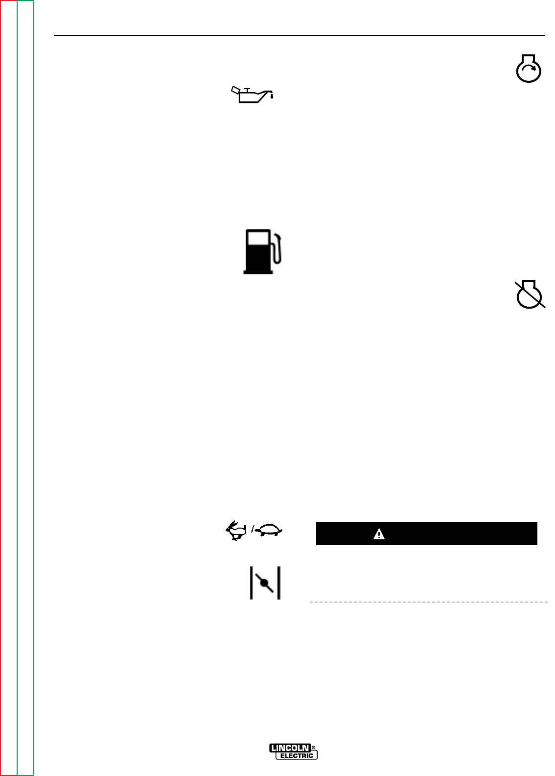
OIL
The RANGER 9 is shipped with the engine
filled with SAE 10W-30 oil. CHECK THE
OIL LEVEL BEFORE YOU START THE ENGINE. This
is an added precaution. When full, the oil level should
be up to but not over the FULL mark on the dipstick.
If it is not full, add enough oil to fill it to the full mark.
For more oil fill and service information, see the
MAINTENANCE section of this manual.
FUEL
Fill the fuel tank with clean, fresh, regular
grade lead-free gasoline. DO NOT MIX
OIL WITH THE GASOLINE.
The RANGER 9 has a 9 gallon (34.1 litre),
bottom mounted fuel tank with a top fill and fuel
gauge. See the Operation and Maintenance sec-
tions of this manual for more details about fuel.
BATTERY CONNECTIONS
The RANGER 9 is shipped with the nega-
tive battery cable disconnected. Before
you operate the machine, make sure the Engine
Switch is in the STOP position and attach the discon-
nected cable securely to the battery terminal. If the
battery is discharged and won’t start the engine, see
the battery charging instructions in the Maintenance
section.
INSTALLATION
A-4 A-4
RANGER 9 RANGER 9
Return to Section TOC Return to Section TOC Return to Section TOC Return to Section TOC
Return to Master TOC Return to Master TOC Return to Master TOC Return to Master TOC
WARNING
–+
CAUTION
MUFFLER RELOCATION
Shut off the machine and allow the muffler to cool
before touching the muffler.
The RANGER 9 is shipped with the exhaust coming
out on the left side. It can be changed to the right side
by removing two screws that hold the exhaust port
cover in place and installing the cover on the opposite
side.
NOTE: Operating the RANGER 9 without the cover in
place will not increase the machine output and
will result in a higher noise level.
SPARK ARRESTER
Gasoline engine mufflers may emit sparks when the
engine is running. Some federal, state, or local laws
require spark arresters in locations where unarrested
sparks could present a fire hazard.
Standard mufflers and deflectors (like the ones includ-
ed with the RANGER 9) do not act as spark arresters.
When local laws require it, a spark arrester must be
installed on the machine and properly maintained. An
optional spark arrester kit (K894-1) is available for your
RANGER 9. See the Accessories section of this man-
ual for more information.
An incorrect spark arrester may lead to damage to the
engine or reduce performance.
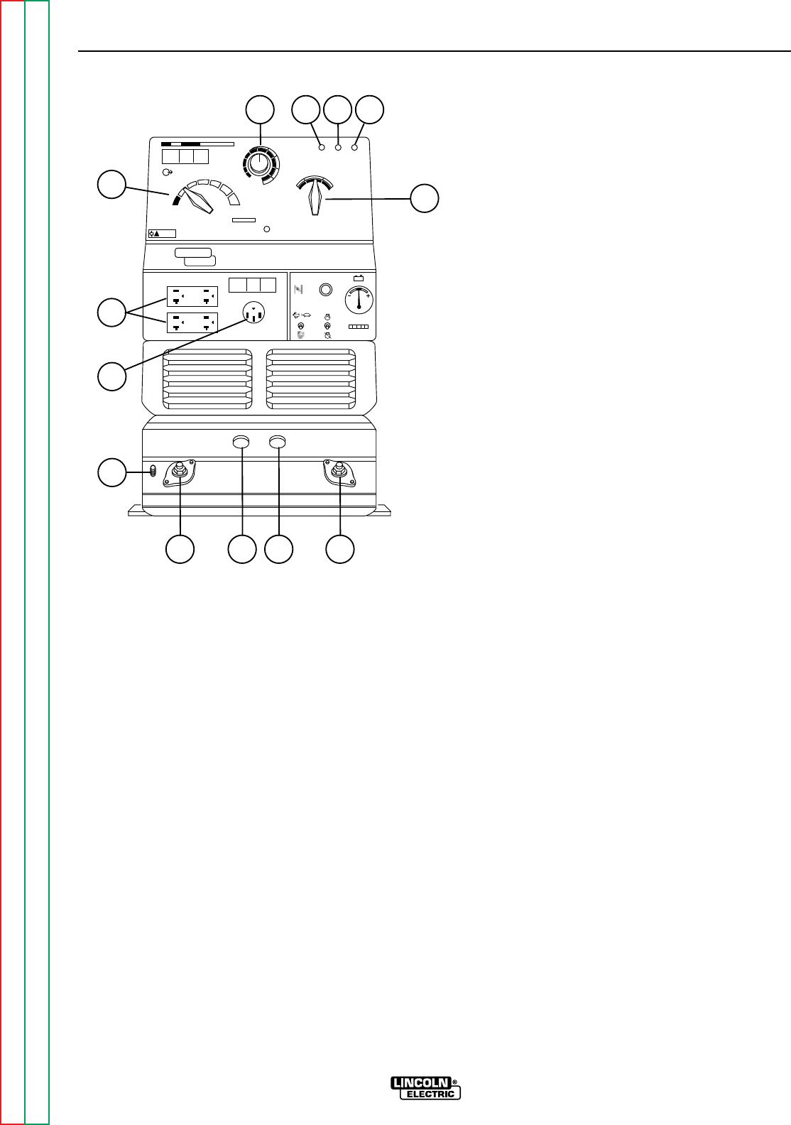
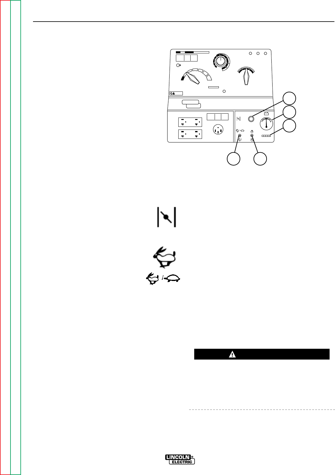
ELECTRICAL OUTPUT
CONNECTIONS
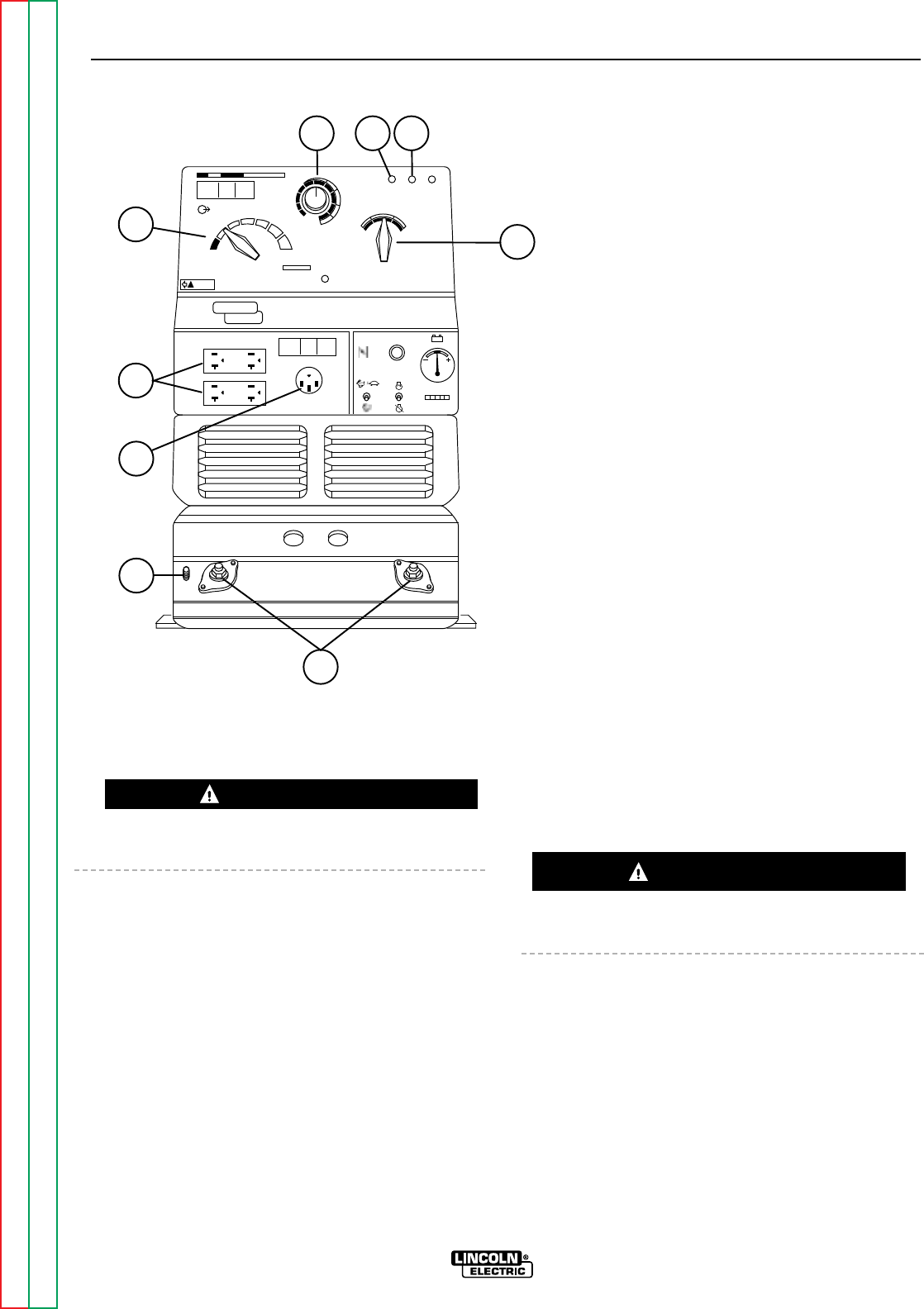
See Figure A.1 for the location of the output range
selector, fine output control, polarity switch, control at
welder/remote control switch, welding terminals
always on/remotely controlled switch 115 and 230 volt
receptacles, weld output terminals, and ground stud.
INSTALLATION
A-5 A-5
RANGER 9 RANGER 9
Return to Section TOC Return to Section TOC Return to Section TOC Return to Section TOC
Return to Master TOC Return to Master TOC Return to Master TOC Return to Master TOC
AC
DC+
DC-
LINCOLN
ELECTRIC
RANGER 9
WARNING
RANGE
175
125
90
70
50
16 to 25
225 AC
210 DC
1
2
3
4
5
10 max
9
8
7
6
5
2
1
7
6
CHOKE
AUTO
HIGH
IDLER
START
RUN
STOP
8
9
43
FIGURE A.1 - RANGER 9 OUTPUT CONNECTIONS
1. OUTPUT RANGE SELECTOR
2. FINE OUTPUT CONTROL
3. CONTROL AT WELDER/REMOTE CONTROL SWITCH
4. WELDING TERMINALS SWITCH
5. POLARITY SWITCH
6. 115/230 VOLT, 50 AMP RECEPTACLE
7. 115 VOLT, 20 AMP RECEPTACLES (2)
8. WELD OUTPUT TERMINALS (2)
9. GROUND STUD
WARNING
CAUTION
WELDING CABLE CONNECTIONS
CABLE SIZE AND LENGTH
Be sure to use welding cables that are large enough.
The correct size and length becomes especially impor-
tant when you are welding at a distance from the
welder.
Table A.1 lists recommended cable sizes and lengths
for rated current and duty cycle. Length refers to the
distance from the welder to the work and back to the
welder. Cable diameters are increased for long cable
lengths to reduce voltage drops.
INSTALLATION
A-6 A-6
RANGER 9 RANGER 9
Return to Section TOC Return to Section TOC Return to Section TOC Return to Section TOC
Return to Master TOC Return to Master TOC Return to Master TOC Return to Master TOC
TABLE A.1 - RECOMMENDED WELDING CABLE SIZE AND LENGTH
TOTAL COMBINED LENGTH OF ELECTRODE AND WORK CABLES
Cable Size for 250 Amp Cable Size for 250 Amp
Cable Length 40% Duty Cycle 100% Duty Cycle
0-50 feet (0-15 meters) 2 AWG 1 AWG
50-100 feet (15-39 meters) 2 AWG 1 AWG
100-150 feet (30-46 meters) 1 AWG 1 AWG
150-200 feet (46-61 meters) 1 AWG 1 AWG
200-250 feet (61-76 meters) 1/0 AWG 1/0 AWG
CABLE INSTALLATION
Install the welding cables to your RANGER 9 as fol-
lows. See Figure A.1 for the location of parts.
1. The gasoline engine must be OFF to install weld-
ing cables.
2. Remove the flanged nuts from the output termi-
nals.
3. Connect the electrode holder and work cables to
the weld output terminals. The terminals are iden-
tified on the case front.
4. Tighten the flanged nuts securely.
5. Be certain that the metal piece you are welding
(the “work”) is properly connected to the work
clamp and cable.
6. Check and tighten the connections periodically.
• Loose connections will cause the output terminals to
overheat. The terminals may eventually melt.
• Do not cross the welding cables at the output termi-
nal connection. Keep the cables isolated and sepa-
rate from one another.
Lincoln Electric offers a welding accessory kit with the
properly specified welding cables. See the Acces-
sories section of this manual for more information.
For more information on welding, see WELDING
OPERATION and SUMMARY OF WELDING PRO-
CESSES in the Operations section of this manual.
MACHINE GROUNDING
Because the RANGER 9 creates its
own power from its gasoline-engine
driven generator, you do not need to
connect the machine frame to an
earth ground. However, for best pro-
tection against electrical shock, connect a heavy
gauge wire (#8 AWG or larger) from the ground stud
located on the bottom of the output panel (see Figure
A.1) to a suitable earth ground such as a metal pipe
driven into the ground.
Do not ground the machine to a pipe that carries
explosive or combustible material.
CAUTION WARNING

When the RANGER 9 is mounted on a
truck or a trailer, the machine generator
ground stud MUST be securely connect-
ed to the metal frame of the vehicle. See
Figure A.1. The ground stud is marked
with the ground symbol.
If the RANGER 9 is connected to premises wiring such
as a home or shop, it must be properly connected to
the system earth ground. See the PREMISES WIRING
section of this manual for details.
AUXILIARY POWER RECEPTACLES,
PLUGS, AND HAND-HELD EQUIPMENT
The control panel of the RANGER 9 features two aux-
iliary power receptacles: See Figure A.1.
• Two 20 amp, 115 volt duplex (double outlet) recep-
tacles.
• One 50 amp 115/230 volt simplex (single outlet)
receptacle.
Through these receptacles the machine can supply up
to 9,000 rated continuous watts of single-phase, 60 Hz
AC power. The machine output voltages fall within ±
10% of the rated voltage.
For further protection against electric shock, any elec-
trical equipment connected to the generator recepta-
cles must use a three-blade, grounded type plug or an
Underwriter’s Laboratories (UL) approved double insu-
lation system with a two-blade plug. Lincoln offers an
accessory plug kit that has the right type of plugs. See
the Accessories section of this manual for details.
If you need ground fault protection for hand-held
equipment, refer to the Accessories section of this
manual for the K896-1 GFCI Receptacle kit.
CIRCUIT BREAKERS
Canadian Standards Association
(CSA) versions of the RANGER 9 are
equipped with 50 amp circuit breakers
on the 115/230 V receptacle and 15
amp circuit breakers on the 115 V receptacles for
overload protection. Under high heat a breaker may
tend to trip at lower loads than it would normally.
Never bypass the circuit breakers. Without overload
protection, the RANGER 9 could overheat and/or
cause damage to the equipment being used.
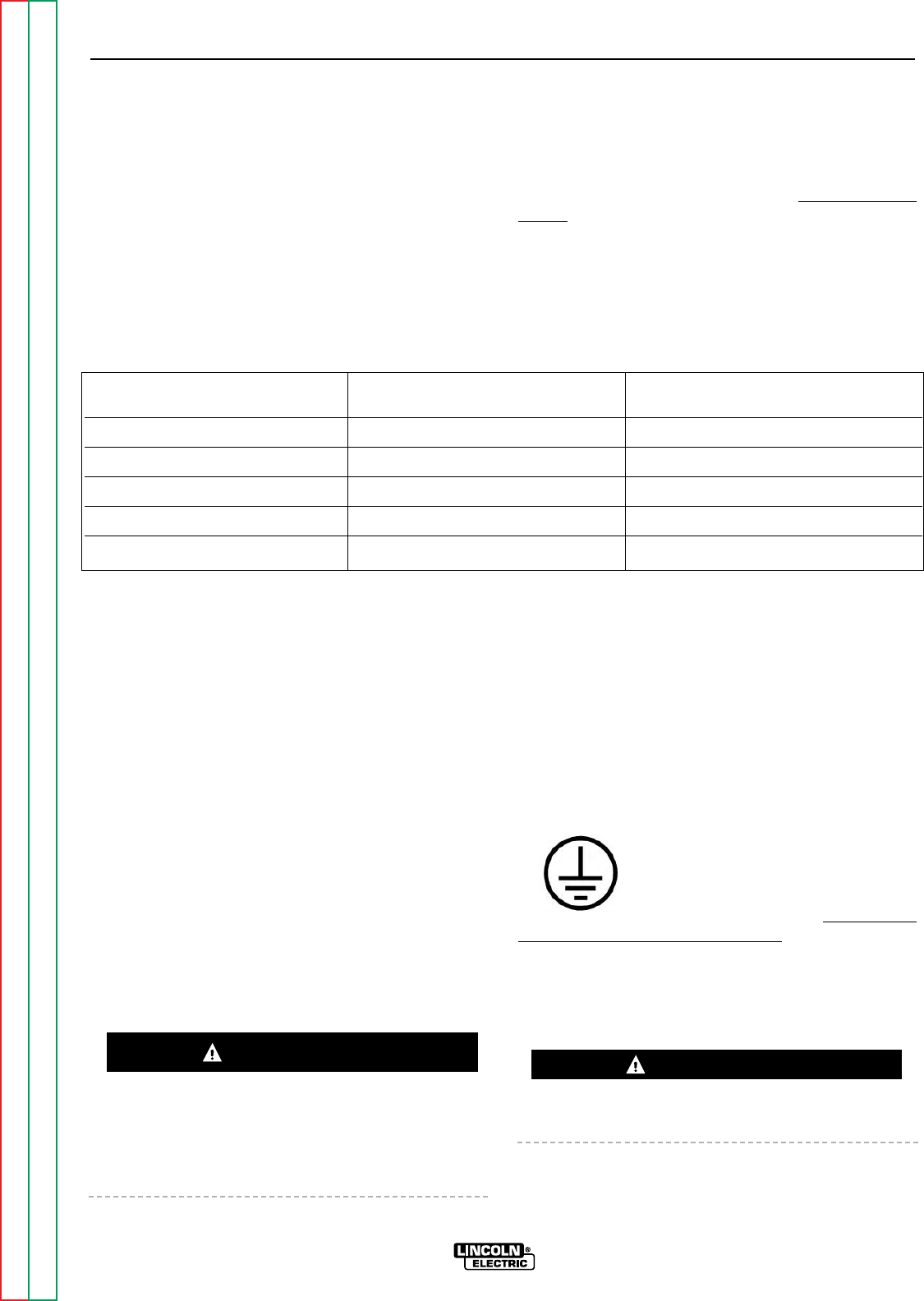
PREMISES WIRING
The RANGER 9 is suitable for temporary, standby, or
emergency power using the engine manufacturer’s
recommended maintenance schedule. With its three-
wire grounded neutral generator, it can be permanent-
ly installed as a standby power unit for 230 volt, three-
wire, single phase 40 ampere service.
Only a licensed, certified, trained electrician should
install the machine to a premises or residential electri-
cal system. Be certain that:
• The installation complies with the National Electrical
Code and all other applicable electrical codes.
• The premises is isolated and no feedbacking into
the utility system can occur. Certain state and local
laws require the premises to be isolated before the
generator is linked to the premises. Check your
state and local requirements.
• A double pole, double throw transfer switch in con-
junction with the properly rated double throw circuit
breaker is connected between the generator power
and the utility meter.
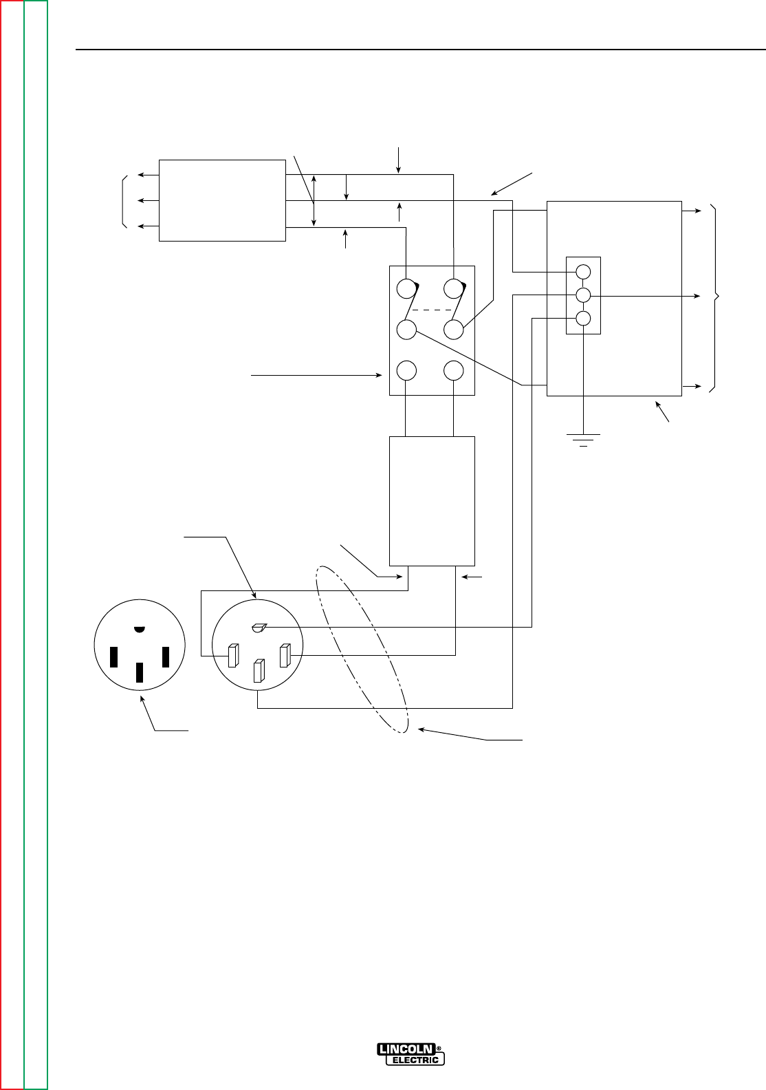
The following information and the connection diagram,
Figure A.2, can be used as a guide by the electrician
for most applications to premises wiring.
1. Install a double pole, double throw switch between
the power company meter and the premises dis-
connect. The switch rating must be the same as
or greater than the premises disconnect and
service overcurrent protection.
2. Take the necessary steps to assure that the load is
limited to the capacity of the RANGER 9 by
installing a 40 amp 230 volt double pole circuit
breaker. Maximum rated load for the 230 volt aux-
iliary is 40 amperes. Loading above 40 amperes
will reduce output voltage below the allowable
– 10% of rated voltage. This may damage appli-
ances or other motor-driven equipment.
3. Install a 50 amp 115/230 volt plug (NEMA type 14-
50) to a double pole circuit breaker using No. 8, 4
conductor cable of the desired length. (The 50
amp 115/230 volt plug is available in the optional
power plug kit. See the Accessories section for
details.)
4. Plug this cable into the 50 amp 115/230 volt
receptacle on the RANGER 9 case front.
INSTALLATION
A-7 A-7
RANGER 9 RANGER 9
Return to Section TOC Return to Section TOC Return to Section TOC Return to Section TOC
Return to Master TOC Return to Master TOC Return to Master TOC Return to Master TOC
WARNING
CAUTION
Return to Section TOC Return to Section TOC Return to Section TOC Return to Section TOC
Return to Master TOC Return to Master TOC Return to Master TOC Return to Master TOC
INSTALLATION
A-8 A-8
RANGER 9 RANGER 9
LOAD
230 Volt
60 Hz.
3-Wire
Service
230 VOLT
GROUNDED CONDUCTOR
115 VOLT
115 VOLT
POWER
COMPANY
METER
DOUBLE POLE DOUBLE THROW
SWITCH RATING TO BE THE SAME
AS OR GREATER THAN PREMISES
SERVICE OVERCURRENT
PROTECTION.
40 AMP
230 VOLT
DOUBLE
POLE
CIRCUIT
BREAKER
GROUND
PREMISES
DISCONNECT AND
SERVICE
OVERCURRENT
PROTECTION
230 VOLTS
GND
N
50 AMP, 115/230
VOLT PLUG
NEMA TYPE 14-50
50 AMP, 115/230 VOLT
RECEPTACLE NOTE: No. 8 COPPER CONDUCTOR CABLE
SEE NATIONAL ELECTRIC CODE FOR
ALTERNATE WIRE SIZE RECOMMENDATIONS.
NEUTRAL
BUS
FIGURE A.2 - CONNECTION OF RANGER 9 TO PREMISES WIRING

Section B-1 Section B-1
RANGER 9 RANGER 9
TABLE OF CONTENTS
- OPERATION SECTION -
Operation...............................................................................................................................Section B
Safety Instructions......................................................................................................................B-2
General Description....................................................................................................................B-2
Recommended Applications ......................................................................................................B-3
Welder .................................................................................................................................B-3
Generator .............................................................................................................................B-3
Operational Features and Controls ............................................................................................B-3
Design Features and Advantages...............................................................................................B-3
Welding Capability......................................................................................................................B-4
Limitations .................................................................................................................................B-4
Controls and Settings ................................................................................................................B-4
Welder/Generator Controls ..................................................................................................B-5
Gasoline Engine Controls.....................................................................................................B-7
Engine Operation........................................................................................................................B-7
Before Starting the Engine ..................................................................................................B-8
Starting the Engine ..............................................................................................................B-8
Stopping the Engine ............................................................................................................B-8
Break-in Period ....................................................................................................................B-8
Welding Operation....................................................................................................................B-10
General Information............................................................................................................B-10
AC/DC Constant Current Stick Welding ......................................................................B-10
AC/DC TIG (Constant Current) Welding.......................................................................B-11
DC Wire Feed Welding.................................................................................................B-12
Summary of Welding Processes...............................................................................................B-13
Auxiliary Power.........................................................................................................................B-14
General Information............................................................................................................B-14
Return to Master TOC Return to Master TOC Return to Master TOC Return to Master TOC
OPERATING INSTRUCTIONS
Read and understand this entire section before oper-
ating your RANGER 9.
SAFETY INSTRUCTIONS
Do not attempt to use this equipment until you have
thoroughly read all the operation and maintenance
manuals supplied with your machine. They include
important safety precautions; detailed engine starting,
operating, and maintenance instructions; and parts
lists.
ELECTRIC SHOCK can kill.
• Do not touch electrically live parts or
electrodes with your skin or wet cloth-
ing.
• Insulate yourself from the work and
ground.
• Always wear dry insulating gloves.
FUMES AND GASES can be dan-
gerous.
• Keep your head out of fumes.
• Use ventilation or exhaust to remove
fumes from breathing zone.
WELDING SPARKS can cause
fire or explosion.
• Keep flammable material away.
• Do not weld on containers that have held
combustibles.
ARC RAYS can burn.
• Wear eye, ear, and body protection.
ENGINE EXHAUST can kill.
• Use in open, well ventilated areas or
vent exhaust to the outside.
• Do not stack anything on or near the
engine.
MOVING PARTS can injure.
• Do not operate this equipment with
any of its doors open or guards off.
• Stop the engine before servicing it.
• Keep away from moving parts.
Only qualified personnel should install, use, or ser-
vice this equipment.
GENERAL DESCRIPTION
The RANGER 9 is a gasoline-engine driven, multi-
process arc welder and AC power generator for com-
mercial and residential applications. As a generator it
can supply up to 9,000 continuous watts of 115/230
volt, 60 Hz, single-phase AC power to operate AC
power tools, battery chargers, and lighting; it can also
be used to provide standby power. As a welder it pro-
vides 250 amps of AC current for welding with AC
stick electrodes or 250 amps of DC current for DC
stick welding. The RANGER 9 can also perform
AC/DC TIG welding and DC semiautomatic wire feed
welding.
The RANGER 9 is powered by the Onan P218
Performer®air-cooled, twin-cylinder engine.
OPERATION
B-2 B-2
RANGER 9 RANGER 9
Return to Section TOC Return to Section TOC Return to Section TOC Return to Section TOC
Return to Master TOC Return to Master TOC Return to Master TOC Return to Master TOC
WARNING
WARNING

RECOMMENDED APPLICATIONS
WELDER
The RANGER 9 provides excellent constant current
AC/DC welding output for stick (SMAW) welding and
for TIG welding, and it offers constant voltage output
for DC semiautomatic wire feed welding. For more
details on using the machine as a welder, see WELD-
ING OPERATION in the Operation section of this
manual.
GENERATOR
The RANGER 9 gives AC generator output for medium
use demands. For more details on operating the gen-
erator, see AUXILIARY POWER in the Operation sec-
tion of this manual.
OPERATIONAL FEATURES AND
CONTROLS
The RANGER 9 was designed for simplicity. There-
fore, it has very few operating controls. Three switch-
es are used for welding operations:
• A nine-position output range selector switch selects
current output for constant current stick or TIG
applications and constant voltage wire feed appli-
cations.
• A fine output control switch for fine adjustment of
current or voltage within the selected output range
• A three-position polarity switch for selecting DC+,
DC- or AC welding output.
• A two-position toggle switch for selecting between
CONTROL AT WELDER or REMOTE CONTROL
(Remote control connections are made at either the
6 pin or the 14 pin amphenol connector.
• A two-position toggle switch for selecting between
control of the output contactor by the RANGER 9
(WELDING TERMINALS ALWAYS ON) or control of
the output contactor by a cable from a wire feeder
gun (WELDING TERMINALS REMOTELY CON-
TROLLED).
The gasoline engine control is a three-position toggle
switch for START, RUN, and STOP and a two-position
“IDLER” switch that selects engine speed for welding
or auxiliary power applications. See ENGINE OPERA-
TION in the Operation section of this manual for
details about starting, running, stopping, and breaking
in the gasoline engine.
DESIGN FEATURES AND
ADVANTAGES
• 9,000 watts of auxiliary power
• Enhanced constant voltage capability with low (12-
21 volts), medium (15-27 volts), and high (18-35
volts) range settings for greater control of wire feed
applications.
• Built-in contactor with front panel selection of
“cold” or “hot” welding terminals: Cold (WELDING
TERMINALS REMOTELY CONTROLLED) – Closing
wire feeder trigger switch or amptrol causes con-
tactor to close and engine to accelerate to high idle.
Hot (WELDING TERMINALS ALWAYS ON) – The
contactor is closed and welding begins when elec-
trode touches work; engine automatically goes to
high idle.
• Constant current AC/DC Stick welding (SMAW)
process capability with output range from 40-250
amps (AC) or 40-250 amps (DC).
• Constant voltage DC Semiautomatic Wire Feed
Welding with output range from 40-250 amps.
• Constant current AC/DC TIG Welding with output
across the entire range of settings.
• Polarity switch for selecting DC+, DC-, or AC weld-
ing output.
• Separate ground stud for safe connection of case to
earth ground.
• Single 50 amp, 230 volt, full 9 kVA auxiliary power
receptacle.
• Double duplex 20 amp, 115 volt auxiliary power
receptacles.
• Electric starting.
• Battery Charging Ammeter.
• Engine Hour Meter for determining periodic mainte-
nance.
• Top-of-the-line 18 HP Onan P218 Performer®
engine.
• Durable, heavy-gauge steel case.
• Built-in feet for easy mounting to truck bed or trailer.
• Bottom-mounted 10 gallon (38.0 litre) fuel tank with
convenient top fill and fuel gauge.
OPERATION
B-3 B-3
RANGER 9 RANGER 9
Return to Section TOC Return to Section TOC Return to Section TOC Return to Section TOC
Return to Master TOC Return to Master TOC Return to Master TOC Return to Master TOC

• Quiet engine muffler with reversible exhaust feature
for right or left side.
• All copper alternator windings and high quality insu-
lation for dependable long life.
• Automatic engine shutdown protection for low oil
pressure.
• Automatic engine idler goes to low idle 10 to 14
seconds after welding for greater fuel economy;
includes high idle switch.
• Standard Remote Control Receptacle provides
interface for Lincoln remote control accessories.
Both 6 pin and 14 pin amphenols are provided for
ease in hooking up wire feeders.
• Canadian Standard Association (CSA) approved
models available; include integrated generator out-
put overload protection through two 50 amp circuit
breakers.
WELDING CAPABILITY
The RANGER 9 is rated 250 amps, 25 volts constant
current AC or 250 amps, 25 volts constant current DC
(250 amps 25 volts constant voltage DC) at 100% duty
cycle on a ten-minute basis.
The current is continuously variable from 40 to 250
amps AC or 40 to 250 amps DC. The RANGER 9 can
weld with all 3/32 and most 1/8 inch and 1/16 diame-
ter Lincoln AC stick electrodes. Wire feed processes
using wire diameters from .030 to .068 inch are possi-
ble, depending on the specific process and wire feed-
er. (See LIMITATIONS.)
LIMITATIONS
• The RANGER 9 is not recommended for any
processes besides those that are normally per-
formed using stick welding (SMAW), TIG welding,
MIG (GMAW) welding and Innershield®(FCAW)
welding. Specific limitations on using the
RANGER 9 for these processes are described in the
WELDING OPERATION section of this manual.
• The RANGER 9 is not recommended for pipe thaw-
ing.
• During welding, generator power is limited and out-
put voltages can drop. Therefore, DO NOT OPER-
ATE ANY SENSITIVE ELECTRICAL EQUIPMENT
WHILE YOU ARE WELDING. See Table B.4 for per-
missible simultaneous welding and auxiliary power
loads.
CONTROLS AND SETTINGS
All generator/welder controls are located on the
Output Control Panel of the machine case front.
Gasoline engine choke control, idler control, and
start/stop controls are also on the case front. See
Figure B.1 and the explanations that follow.
OPERATION
B-4 B-4
RANGER 9 RANGER 9
Return to Section TOC Return to Section TOC Return to Section TOC Return to Section TOC
Return to Master TOC Return to Master TOC Return to Master TOC Return to Master TOC
Return to Section TOC Return to Section TOC Return to Section TOC Return to Section TOC
Return to Master TOC Return to Master TOC Return to Master TOC Return to Master TOC
OPERATION
B-5 B-5
RANGER 9 RANGER 9
AC
DC+
DC-
LINCOLN
ELECTRIC
RANGER 9
WARNING
RANGE
175
125
90
70
50
16 to 25
225 AC
210 DC
1
2
3
4
5
10 max
9
8
7
6
3
2
1
7
8
CHOKE
AUTO
HIGH
IDLER
START
RUN
STOP
9
11
54 6
1012 13
FIGURE B.1 – OUTPUT PANEL CONTROLS
1. OUTPUT RANGE SELECTOR
2. FINE OUTPUT CONTROL
3. POLARITY SWITCH
4. CONTROL AT WELDER/REMOTE CONTROL SWITCH
5. WELDING TERMINALS ALWAYS ON/
WELDING TERMINALS REMOTELY CONTROLLED SWITCH
6 WIRE FEEDER POWER CIRCUIT BREAKER
7. 115 VOLT, 20 AMP RECEPTACLES (2)
8. 115/230 VOLT, 50 AMP RECEPTACLE
9. WELD OUTPUT TERMINAL (TO WORK)
10. WELD OUTPUT TERMINAL (TO ELECTRODE HOLDER)
11. GROUND STUD
12. 14 PIN AMPHENOL
13. 6 PIN AMPHENOL
WELDER/GENERATOR CONTROLS
See Figure B.1 for the location of the following fea-
tures:
1. OUTPUT RANGE SELECTOR: Selects continuous
current output for constant current stick or TIG
applications (blue settings) and constant voltage
wire feed applications (red settings). The amper-
ages on the dial correspond to the maximum
amperages for each corresponding range setting.
Never change the range switch setting while
welding since this could damage the switch.
2. FINE OUTPUT CONTROL: Allows fine adjustment
of current or voltage within the selected output
range.
3. POLARITY SWITCH: Selects DC+, DC- or AC
welding output. Color codings aid in the proper
selection of stick (blue) or wire feed (red) polarity
setting. The color setting of the polarity switch
must match the color setting of the OUTPUT
RANGE SELECTOR. Never change the polarity
switch setting while welding since this could
damage the switch.
4. CONTROL AT WELDER/REMOTE CONTROL
SWITCH: Allows the operator to control welding
output at the welding control panel or at a remote
station. Remote connections are made at the 6 pin
or 14 pin amphenol connector.
5. WELDING TERMINALS ALWAYS ON/WELDING
TERMINALS REMOTELY CONTROLLED SWITCH:
Allows control of the RANGER 9 output contactor.
In the ALWAYS ON position, the switch closes the
output contactor, and welding begins when an arc
is struck between the electrode and the workpiece.
In the REMOTELY CONTROLLED position, the
switch places control of the contactor at the wire
feeder. The contactor closes when the wire feeder
gun trigger or amptrol switch closes and opens
when it is released.
6. WIRE FEEDER POWER CIRUIT BREAKER: Opens
the wire feeder circuit and disables the feeder if a
fault is detected in the circuit.

7. 20 AMP, 115 VOLT DUPLEX RECEPTACLES:
Connection point for supplying 115 volt power to
operate one or two electrical devices.
8. 50 AMP, 230 VOLT RECEPTACLE: Connection
point for supplying 230 volt power to operate one
electrical device.
9. WELD OUTPUT TERMINAL (TO WORK) WITH
FLANGE NUT: Provides the connection point for
the work cable.
10. WELD OUTPUT TERMINAL (TO ELECTRODE
HOLDER) WITH FLANGE NUT: Provides the con-
nection point for the electrode holder.
11. GROUND STUD: Provides a connection point for
connecting the machine case to earth ground for
the safest grounding procedure.
12. 14 PIN AMPHENOL: For attaching wire feeder
control cables to the RANGER 9.
13. 6 PIN AMPHENOL: For attaching optional remote
control equipment to the RANGER 9.
OPERATION
B-6 B-6
RANGER 9 RANGER 9
Return to Section TOC Return to Section TOC Return to Section TOC Return to Section TOC
Return to Master TOC Return to Master TOC Return to Master TOC Return to Master TOC
GASOLINE ENGINE CONTROLS
See Figure B.2 for the location of the following fea-
tures:
1. ENGINE CHOKE CONTROL: Provides
a richer air/fuel mixture for cold engine
starting conditions. See the topic
ENGINE OPERATION, below, for details
on setting the choke.
2. IDLER CONTROL SWITCH: Adjusts
the running speed of the engine. The
switch has two positions, HIGH and
AUTO. In HIGH, the engine runs con-
tinuously at high idle. In AUTO, the
idler control works as follows:
Stick Welding, “WELDING TERMINALS ALWAYS
ON” mode: The engine accelerates to high speed
when the electrode touches the work and strikes a
welding arc. The engine returns to low idle ap-
proximately 10-14 seconds after welding stops, as
long as no auxiliary power is being drawn.
Wire Welding, “WELDING TERMINALS ALWAYS
ON” mode: The engine accelerates to high speed
when the wire feeder gun trigger or amptrol is
closed. The engine returns to low idle approxi-
mately 10-14 seconds after the gun trigger is
released and the welding stops, provided that no
auxiliary power is being drawn.
Auxiliary Power: The engine accelerates to high
speed when power is drawn at the receptacles for
lights or tools. The engine returns to low idle
approximately 10-14 seconds after demand for
auxiliary power stops.
3. START/STOP SWITCH: Has three positions,
START, RUN, and STOP. When the switch is held
in the START position, the starter motor cranks
over the engine – release the switch once the
engine starts. The STOP position stops the
engine.
NOTE: If you place the switch in the START posi-
tion when the engine is running, you may damage
the ring gear or starter motor.
4. ENGINE HOUR METER: Records engine running
time. Use the meter to determine when to perform
required maintenance.
5. BATTERY CHARGING SYSTEM METER: Shows
whether the charging circuit is performing its job of
charging the battery when the engine is running.
The meter will register discharge during starting,
but then the needle should return to a position
slightly toward positive during running. The needle
will hold position when the engine stops.
ENGINE OPERATION
DO NOT RUN THE ENGINE AT EXCESSIVE SPEEDS.
The maximum allowable high idle speed for the
RANGER 9 is 3750 RPM, no load. Do NOT adjust the
governor screw on the engine. Severe personal injury
and damage to the machine can result if it is operated
at speeds above the maximum rated speed.
Read and understand all safety instructions included in
the Onan instruction manual that is shipped with your
RANGER 9.
OPERATION
B-7 B-7
RANGER 9 RANGER 9
Return to Section TOC Return to Section TOC Return to Section TOC Return to Section TOC
Return to Master TOC Return to Master TOC Return to Master TOC Return to Master TOC
FIGURE B.2 – GASOLINE ENGINE CONTROLS
AC
DC+
DC-
LINCOLN
ELECTRIC
RANGER 9
WARNING
RANGE
175
125
90
70
50
16 to 25
225 AC
210 DC
1
2
3
4
5
10 max
9
8
7
6
1
2
CHOKE
AUTO
HIGH
IDLER
START
RUN
STOP
3
5
4
1. ENGINE CHOKE CONTROL
2. IDLER CONTROL SWITCH
3. START/STOP SWITCH
4. ENGINE HOUR METER
5. BATTERY CHARGING SYSTEM METER
WARNING
BEFORE STARTING THE ENGINE
Check and fill the engine oil level:
1. Be sure the machine is on a level
surface.
2. Remove the engine oil dipstick and wipe it with a
clean cloth. Reinsert the dipstick and check the
level on the dipstick. On the Onan engine, the oil
fill cap and dipstick are a unit. See Figure D.1 in
the Maintenance section of this manual.
3. Add oil (if necessary) to bring the level up to the
full mark. Do not overfill.
Replace the dipstick and tighten it securely.
Check and fill the engine fuel tank:
1. Remove the fuel tank cap.
2. Fill the tank approximately 4 inches
(100 mm) from the top of the filler neck to allow for
fuel expansion (observe the fuel gauge). DO NOT
FILL THE TANK TO THE POINT OF OVERFLOW.
3. Replace the fuel tank cap and tighten securely.
NOTE: Use only fresh, unleaded gasoline with octane
rating 87 or higher. Gasoline/alcohol blends are
approved for use with your engine as long as the blend
does not exceed 10% ethyl alcohol by volume. Other
gasoline/alcohol blends are not approved, and their
use may damage fuel system and engine parts.
NOTE: Purchase gasoline in quantities that will be
used within 30 days, to assure freshness.
STARTING THE ENGINE
NOTE: Remove all loads connected to the AC power
receptacles before starting the gasoline engine.
For a “cold” engine:
1. Set the Idler Control Switch in
the AUTO position.
Use the Choke Control as follows:
If the engine is cold, pull the choke
control out. If the engine is warm or
hot, DO NOT use the choke control.
2. Hold the Engine Switch in the START
position. Release the switch when the
engine starts. Slowly return the choke
control to the full “in” position.
The engine will run at high idle for 10-14 seconds,
then go to low idle.
3. Let the engine run at low idle for a few minutes to
warm up before you use the RANGER 9 for weld-
ing or auxiliary power.
If the engine will not start, see the Trouble-
shooting section of this manual.
STOPPING THE ENGINE
1. Remove all welding and generator power loads
and let the engine cool by running it for several
minutes at low idle.
2. Stop the engine by placing the Engine
Switch in the STOP position.
A fuel shutoff valve is not required on the
RANGER 9 because the fuel tank is mounted
below the engine.
BREAK-IN PERIOD
Any engine will use a small amount of oil during its
“break-in” period. For the gasoline engine on the
RANGER 9, break-in is about 50 running hours.
Check the oil at least twice a day during break-in.
Change the oil after the first 25 hours of operation.
Change the oil filter at the second oil change. For
more details, see the Maintenance section of this
manual.
During break-in, subject the RANGER 9 to moderate
loads. Avoid long periods running at idle. Before
stopping the engine, remove all loads and allow the
engine to cool several minutes.
OPERATION
B-8 B-8
RANGER 9 RANGER 9
Return to Section TOC Return to Section TOC Return to Section TOC Return to Section TOC
Return to Master TOC Return to Master TOC Return to Master TOC Return to Master TOC
CAUTION

OPERATION
B-9 B-9
RANGER 9 RANGER 9
Return to Section TOC Return to Section TOC Return to Section TOC Return to Section TOC
Return to Master TOC Return to Master TOC Return to Master TOC Return to Master TOC
TABLE B.1
TYPICAL RANGER 9 FUEL CONSUMPTION
ONAN P218 PERFORMER
Low Idle – No Load, 2150 RPM .40 Gallons/hour (1.5 liters/hour)
High Idle – No Load, 3700 RPM .82 Gallons/hour (3.10 liters/hour)
AC CC Weld Output, 250 Amps @ 25 Volts 1.7 Gallons/hour (6.5 liters/hour)
DC CC Weld Output, 250 Amps @ 25 Volts 1.7 Gallons/hour (6.5 liters/hour)
DC CV Weld Output, 250 Amps @ 25 Volts 1.7 Gallons/hour (6.5 liters/hour)
Auxiliary Power, 9000 kVA 1.7 Gallons/hour (6.5 liters/hour)
WELDING OPERATION
GENERAL INFORMATION
• Do not touch electrically live parts or elec-
trodes with your skin or wet clothing.
• Do not breathe welding fumes or gases.
• Use ventilation or exhaust to remove
welding fumes from the breathing area.
• Keep flammable material away.
• Wear eye, ear, and body protection.
The RANGER 9 can deliver from 40 to 250 amps of
constant current for AC/DC stick welding or from 40 to
250 amps of constant voltage current for DC semiau-
tomatic wire feed welding. AC/DC TIG welding is pos-
sible across the entire range from 40 to to maximum
rated output. Output can be adjusted by setting the
POLARITY SWITCH, the OUTPUT RANGE dial, and
the FINE CONTROL dial on the output control panel to
the settings that are best for your selected welding
process.
To use the RANGER 9 for AC/DC
Constant Current Stick Welding:
1. Remove the flange nuts from output terminals and
place the work and electrode welding cables over
the terminals. See Figure B.3. Replace and tight-
en the flange nuts securely. Be sure the connec-
tions are tight.
2. Select the appropriate electrode. See “Welding
Tips 1” included with your RANGER 9.
3. Attach the work clamp securely to the work you
are welding.
4. Insert the electrode into the electrode holder.
5. Set the IDLER CONTROL to AUTO and start the
gasoline engine. See ENGINE OPERATION in this
section of the manual.
6. Set the OUTPUT RANGE dial to a setting equal to
or slightly higher than the welding current recom-
mended for the electrode being used.
7. Set the POLARITY SWITCH to the desired polarity.
8. Set the FINE OUTPUT CONTROL. Use a setting
that results in the highest output at the lowest set-
ting of the RANGE switch for the application.
9. Strike an arc and begin welding.
After you finish welding:
1. Stop the gasoline engine. See ENGINE OPERA-
TION in this section of the manual.
2. Allow the electrode and work to cool completely.
3. Remove the work clamp from the work.
4. Remove any remaining piece of electrode from the
electrode holder.
5. If you are finished using the RANGER 9 for weld-
ing, disconnect the welding cables from the weld
output terminals. Reattach the flange nuts and
leave them on the terminals.
OPERATION
B-10 B-10
RANGER 9 RANGER 9
Return to Section TOC Return to Section TOC Return to Section TOC Return to Section TOC
Return to Master TOC Return to Master TOC Return to Master TOC Return to Master TOC
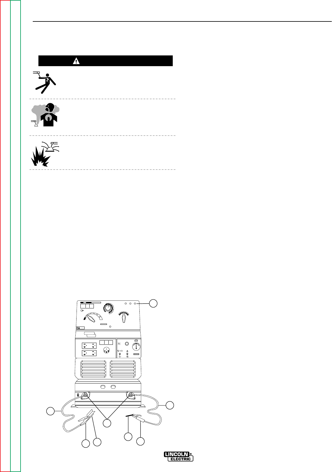
WARNING
FIGURE B.3 – WELDING CIRCUIT CONNECTIONS FOR STICK WELDING
8
AC
DC+
DC-
LINCOLN
ELECTRIC
RANGER 9
WARNING
RANGE
175
125
90
70
50
16 to 25
225 AC
210 DC
1
2
3
4
5
10 max
9
8
7
61
CHOKE
AUTO
HIGH
IDLER
START
RUN
STOP
74
6
5
3
2
1. OUTPUT CONTROL PANEL
2. ELECTRODE CABLE
3. ELECTRODE HOLDER
4. ELECTRODE
5. OUTPUT TERMINALS
6. WORK
7. WORK CLAMP
8. WORK CABLE

To Use the RANGER 9 for AC/DC TIG
(Constant Current) Welding:
1. Connect the K930-1 TIG Module to the RANGER
9. Follow the installation instructions provided
with the kit. Also be sure to follow the special
machine grounding instructions given in the man-
ual.
2. Refer to the instruction manual with the TIG mod-
ule (IM 528) for operation with a RANGER 9 and
proper machine settings.
3. Set the OUTPUT RANGE dial to the appropriate
setting for the electrode you are using. Refer to
IM -528 with the TIG module or refer to Table B.2
for AC TIG welding.
4. Set the POLARITY SWITCH to the desired polarity.
5. Do not AC TIG weld on the 250 AC range setting.
The output current may exceed the rating of the
RANGER 9.
6. Start the arc and begin welding.
NOTE: When using the RANGER 9 for AC TIG weld-
ing of aluminum, the TIG Module is to be set
for CONTINUOUS HF.
After you finish welding:
1. Stop the gasoline engine. See ENGINE OPERA-
TION in this section of the manual.
2. Allow the electrode and work to cool completely.
3. Remove the work clamp from the work.
OPERATION
B-11 B-11
RANGER 9 RANGER 9
Return to Section TOC Return to Section TOC Return to Section TOC Return to Section TOC
Return to Master TOC Return to Master TOC Return to Master TOC Return to Master TOC
TABLE B.2 - AC TIG WELDING – TIG ELECTRODE/RANGE SETTINGS
Settings for Pure Tungsten
Tungsten Diameter (inches) Range Switch Settings Appropriate Current Range
1/8 90 or 120 160 - 200 Amps
3/32 45 or 90 45 - 140 Amps
1/16 45 or 90 45 - 100 Amps
Settings for 1% Thoriated Tungsten
Tungsten Diameter (inches) Range Switch Settings Appropriate Current Range
1/8 90, 120, or 180 160 - 250 Amps
3/32 45, 90, or 120 100 - 180 Amps
1/16 45 or 90 60 - 120 Amps

To Use the RANGER 9 for DC Wire Feed
Welding (Constant Voltage):
1. Connect one of the following: the LN-25, LN-7,
LN-8, or LN-742 Wire Feeder. Follow the installa-
tion instructions in the ACCESSORIES section of
this manual.
2. Some recommended Innershield electrodes are:
NR-211MP, NR-311, NR-203 series, as well as
Lincore®33 and 55 hardfacing electrodes.
Diameters from .035 (0.9mm) up to and including
5/64” (2.0mm) can be used. 5/64” (2.0mm) NS-
3M can be used in limited applications. Cable
length and other conditions can affect the ultimate
results of this application. Request Lincoln publi-
cation N-675 for additional information.
Recommended Outershield electrodes are .045,
.052, and 1/16 Outershield 71 and 1/16
Outershield 70. Request Lincoln publication
GS-200 for additional information.
For MIG welding, the recommended electrodes
are .030, .035 and .045 L-50 and L-56. You must
use a blended shielding gas such as C25 (75%
Argon, 25% CO2). Request Lincoln publication
GS-100 for additional information.
3. Set the IDLER CONTROL to “AUTO” for the LN-25
or LN-742 or “HIGH” for the LN-7 or LN-8 and
start the gasoline engine. See ENGINE OPERA-
TION in this section of the manual.
4. Set the OUTPUT RANGE dial to either HIGH,
MED, or LOW depending on your wire size and
speed.
5. Set the POLARITY SWITCH to either WIRE FEED
DC+ or WIRE FEED DC- (red), depending on the
electrode.
6. Set the FINE OUTPUT CONTROL to a setting that
gives the most stable arc for the application.
7. Strike an arc and begin welding.
After you finish welding:
1. Stop the gasoline engine. See ENGINE OPERA-
TION in this section of the manual.
2. Allow the work to cool completely. The wire gun
and wire are “cold.”
3. Remove the work clamp from the work.
OPERATION
B-12 B-12
RANGER 9 RANGER 9
Return to Section TOC Return to Section TOC Return to Section TOC Return to Section TOC
Return to Master TOC Return to Master TOC Return to Master TOC Return to Master TOC

SUMMARY OF WELDING
PROCESSES AND MACHINE
SETTINGS
Table B.3 summarizes the requirements for various
welding processes you can perform with the
RANGER 9.
OPERATION
B-13 B-13
RANGER 9 RANGER 9
Return to Section TOC Return to Section TOC Return to Section TOC Return to Section TOC
Return to Master TOC Return to Master TOC Return to Master TOC Return to Master TOC
TABLE B.3 - SUMMARY OF WELDING PROCESSES
Process Control Idle Output Welding Electrode To Start Welding
Cable Mode Control Terminals State When
Used Switch Switch Not Welding
Stick – CC No Auto At Welder Always on Hot Touch electrode to work.
Welding starts immedi-
ately and engine goes to
high idle.
TIG - CC Yes Auto Remote Remote Cold Press Amptrol. Welding
K930-1/K936-1 starts immediately.
(With Amptrol)
Wire Feed - CV, Yes Auto Remote Remote Cold Press gun trigger,
LN-25 with 42V RANGER 9 contactor
Remote Control Kit closes. Welding starts
immediately and engine
goes to high idle.
Wire Feed - CV No Auto At Welder Always on Cold Press gun trigger, LN-25
LN-25 with internal contactor closes. Weld-
contactor ing starts immediately
and engine goes to high
idle.
Wire Feed - CV Yes Auto Remote Remote Cold Press gun trigger,
LN-742 RANGER 9 contactor
closes. Welding starts
immediately and engine
goes to high idle.
Wire Feed - CV, Yes High Remote Remote Cold Press gun trigger,
LN-7 RANGER 9 contactor
closes. Welding starts
immediately.

AUXILIARY POWER
Be sure that any electrical equipment plugged into the
generator AC power receptacles can withstand a
±10% voltage and a ±3% frequency variation.
GENERAL INFORMATION
The RANGER 9 generator is rated at 9000 continuous
watts. It provides both 115 volt and 230 volt power.
You can draw up to 80 amps total from the 115 volt
receptacles, but no more than 20 amps (15 amps CSA)
from each receptacle at once. See Tables B.4A and
B.4B. Up to 40 amps can be drawn from the single 230
volt receptacle.
The current rating of any plug used must be at least
equal to the current load being drawn from the recep-
tacle. Do not try to connect the receptacles in paral-
lel.
Electrical loads in watts are calculated by multiplying
the voltage rating of the load by the number of amps it
draws. (This information is given on the load device
nameplate.) For example, a device rated 115 volts, 2
amps will need 230 watts of power (115 x 2 = 230).
You can use Table B.6, GENERATOR POWER APPLI-
CATIONS, to determine the wattage requirements of
some common types of loads you can power with the
RANGER 9. Be sure to read the notes at the bottom
of the table.
Powering Motors
You can start most 1.5 HP, single-phase electric
motors if there is no load on the motor or other load
connected to the RANGER 9. After starting, the motor
may be run at full load. Larger motors (up to 2 HP)
may be started and run as long as you don’t exceed
the current rating of the receptacle. This may mean
that only 230 volt motors of this size may be operated.
Using Auxiliary Power and Welding at the
Same Time
It is possible to weld and use the RANGER 9 for auxil-
iary power at the same time. However, the size of the
loads you can power is reduced when you weld. See
Table B.5 in this section of the manual for a list of per-
missible simultaneous welding and load ratings. The
table assumes that power is being drawn from either a
115 volt or the 230 volt receptacle, but not both at the
same time.
NOTE: For simultaneous welding and power, set the
OUTPUT CONTROL at “10” for maximum auxiliary
power. At settings below “10,” only incandescent
loads should be connected to the auxiliary recepta-
cles.
To use the generator as an auxiliary power supply:
1. Start the gasoline engine. See ENGINE OPERA-
TION in this section of the manual.
2. Set the IDLER CONTROL to the desired operating
mode, HIGH or AUTO. Set the OUTPUT CON-
TROL to “10.” See Figure B.1.
3. Plug the load(s) into the appropriate 115 volt or
230 volt power receptacle.
NOTE: The 115 volt auxillary power receptacles
should only be used with three-wire grounded
type plugs or approved double insulated
devices with two-wire plugs.
OPERATION
B-14 B-14
RANGER 9 RANGER 9
Return to Section TOC Return to Section TOC Return to Section TOC Return to Section TOC
Return to Master TOC Return to Master TOC Return to Master TOC Return to Master TOC
WARNING
TABLE B.4A
MAXIMUM CURRENT DRAW FROM 115V DUPLEX
RECEPTACLES – NO WELDING
K1420-1 K1420-2 (CSA)
Load From Each Total Each Total
115V/230V Half of from Half of from
Dual Voltage Each 115V Both 115V Each 115V Both 115V
Receptacle Duplex Duplexes Duplex Duplexes
0 20* 78 15 60
2.2 KW 20* 60 15 60
4.5 KW 20* 40 15 40
6.7 KW 20* 20 15 20
9.0 KW 0 0 0 0
*NEMA 5-20P plug required for 20 amp draw.
TABLE B.4B
MAXIMUM CURRENT DRAW FROM OPTIONAL
115V GFCI DUPLEX RECEPTACLES – NO WELDING
K1420-1* K1420-2**
Load From Each Total Each Total
115V/230V Half of from Half of from
Dual Voltage Each 115V Both 115V Each 115V Both 115V
Receptacle Duplex Duplexes Duplex Duplexes
015401530
2.2 KW 15 40 15 30
4.5 KW 15 40 15 30
6.7 KW 15 20 15 20
9.0 KW 0 0 0 0
*Maximum current draw from each 115V GFCI Duplex is 20 amps.
**Maximum current draw from each 115V GFCI Duplex is 15 amps.
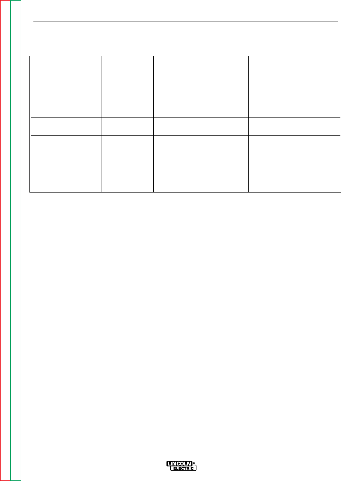
OPERATION
B-15 B-15
RANGER 9 RANGER 9
Return to Section TOC Return to Section TOC Return to Section TOC Return to Section TOC
Return to Master TOC Return to Master TOC Return to Master TOC Return to Master TOC
TABLE B.5 - SIMULTANEOUS WELDING AND AUXILIARY POWER
Output Selector Welding Permissible Power in Watts Permissible Auxiliary Current
Setting Output (Unity Power Factor) in Amperes
@ 115V @230V
250 250 None — —
200 200 2500 22 11
160 160 3700 32 16
120 120 5000 44 22
90 90 6000 52 26
45 45 7500 65 32.5
CV Low 200 5000 43 21.5
60 7500 65 32.5
CV Medium 250 2750 40 20
80 6500 56 28
CV High 250 1200 10 5
100 6000 52 26

TABLE B.6
TYPICAL GENERATOR POWER APPLICATIONS
Suggested Power Applications Running Watts *Start-up Watts
*Air Compressor - 3/4 HP 1,250 3,100 - 5,000
*Airless Sprayer - 1/3 HP 600 1,500 - 2,400
Chain Saw 1,200
Circular Saw 1,200
Coffee Maker 1,000
*Deep Freezer 500 750 - 2,000
*Electric Motor - 1 HP 1,000 2,500 - 4,000
Electric Range (1 element) 1,500
Electric Skillet 1,250
*Furnace Fan - 1/3 HP 1,200 3,000 - 4,800
Portable Grinder (4 1/2”) 600
Portable Grinder (7”) 2,000
Halogen Work Light 500
Hand Drill - 1/4” 500
Hand Drill - 3/8” 700
1500 Watt Heater 1,750
Hedge Trimmer 450
Light Bulb 100
Reciprocating Saw 900
Radial Arm Saw 2,600
Radio 50
*Refrigerator/Freezer (small) 600 1,500 - 2,400
Slow Cooker 200
*Submersible Pump - 1 HP 1,000 2,500 - 4,000
*Sump Pump 600 1,500 - 2,400
Toaster 1,100
Weed Trimmer 500
Lincoln 100 or 125 Amp Wire Feeder/Welder 4,000
OPERATION
B-16 B-16
RANGER 9 RANGER 9
Return to Section TOC Return to Section TOC Return to Section TOC Return to Section TOC
Return to Master TOC Return to Master TOC Return to Master TOC Return to Master TOC
NOTES:
Wattages listed are approximate. Check your equipment for actual wattage.
Equipment with unusually high *START-UP WATTS are listed. For start-up of other equipment listed in the
table, multiply RUNNING WATTS by 2.
Multiple loads can be used as long as the total load does not exceed 9,000 watts. Be sure to start the
largest loads first. For example, a 1 HP motor needs approximately 1,000 watts while running but may
require 2,500 watts to start. Some inductive motors may require as much as 4 times running watts to
start.

TABLE OF CONTENTS
- ACCESSORIES -
Accessories...........................................................................................................................Section C
Options/Accessories...................................................................................................................C-2
TIG Welding..........................................................................................................................C-3
Semiautomatic FCAW and MIG Welding.............................................................................C-3
Connection of Lincoln Electric Wire Feeders.......................................................................C-4
Connection of the K867 Universal Adapter...................................................................C-4
Connection of the LN-25 “Across the Arc” ...................................................................C-5
Connection of the LN-25 with 42V Remote Output Control Module ............................C-6
Connection of the LN-7 Using the K584 Input Cable Assembly...................................C-7
Connection of the LN-7 Using the K867 Universal Adapter .........................................C-8
Connection of the LN-8 .................................................................................................C-9
Connection of the LN-742 ...........................................................................................C-10
Connection of the K488 SG Control Module and the K487 Magnum Spool Gun......C-11
Section C-1 Section C-1
RANGER 9 RANGER 9
Return to Master TOC Return to Master TOC Return to Master TOC Return to Master TOC

OPTIONS/ACCESSORIES
The following options/accessories are available for
your RANGER 9 from your local Lincoln Distributor.
Two-Wheel Trailer (K768-2) – For in-plant or yard
towing of the RANGER 9. (Not intended for highway
towing as equipped. For highway use of this trailer,
consult applicable federal, state, and local laws about
possible requirements for brakes, lights, fenders, etc.
Two-Wheel Undercarriage (K889-2) – For moving the
RANGER 9 by hand. Overall width is 29 inches
(74 mm).
Caster for Undercarriage (K893-1) – Mounts to the
front of the K889-2 to allow easy movement on
smooth surfaces. Includes a 6 inch (152.4 mm) diam-
eter hard rubber wheel and convenient toe-on, toe-off
locking brake.
Four-Wheel Undercarriage (K933-1) – Allows move-
ment of the RANGER 9 by hand without lifting. Easily
assembles to RANGER 9. Includes two rugged, hard
molded wheels and two durable pneumatic tires. The
spring loaded handle provides convenient, comfort-
able steering. The K934-1 Bracket is available for
mounting a gas cylinder on the undercarriage.
Bracket for Mounting a Gas Cylinder to a K933-1
Undercarriage (K934-1) – Easily mounts on the back
of the K933-1 Four Wheel Undercarriage to carry a
welding gas cylinder.
Canvas Cover (K886-1) – For protecting the
RANGER 9 when it’s not in use. Material is flame retar-
dant, mildew resistant, and water repellent. Color: red.
Power Plug Kit (K802-N) – Provides four 20 amp, 115
volt plugs and one 50 amp, dual voltage (115/230V),
full kVA plug. NOTE: For CSA machines K1418-2 or
K1419-2 and machines with GFCI receptacles, use
Power Plug Kit K802-R.)
Power Plug Kit (K802-R) –Provides four 15 amp, 115
volt plugs and one 50 amp, dual voltage (115/230V),
full kVA plug.
Accessory Kit (K702) – Includes the following:
• Thirty-five feet (10.5 meters) of #2 AWG electrode
cable
• Thirty feet (9.1 meters) of #2 AWG work cable
• Headshield with No. 12 filter.
• GC300 work clamp
• Cooltong®300 insulated electrode holder
The cables are rated at 250 amps, 40% duty cycle.
Spark Arrester Kit (K894-1) – A field-installed kit for
the RANGER 9 gasoline engine muffler exhaust pipe
(either engine option). Includes a heavy-gauge steel,
approved spark arrester and mounting clamp.
Rotor Removal Kit (S20788) – A service kit with thru
and impact bolts for removing the generator rotor from
the tapered engine crankshaft.
Remote Control (K857) – Includes a control box with
25 feet (7.5 meters) of 4-conductor cable. Allows out-
put voltage to be controlled remotely.
GFCI Receptacle Kit (K896-1) – Includes two UL
approved 115 volt ground fault circuit interrupter
receptacles (duplex type) with covers and installation
instructions. Each receptacle is rated 15 amps, but
the maximum total current from each GFCI duplex is
limited to 20 amps. The GFCI receptacles replace the
two factory installed 115 volt duplex receptacles.
ACCESSORIES
C-2 C-2
RANGER 9 RANGER 9
Return to Section TOC Return to Section TOC Return to Section TOC Return to Section TOC
Return to Master TOC Return to Master TOC Return to Master TOC Return to Master TOC

TIG WELDING
TIG Module (K930-1) - The TIG Module is an acces-
sory that provides high frequency and shielding gas
control for AC and DC GTAW (TIG) welding applica-
tions. It provides contactor control of constant current
welding power sources having an internal contactor.
The K930-1 TIG Module is supplied without accessories.
Arc Start switches, Amptrols, cables, torches and
mounting brackets must be purchased separately.
Docking Kit (K939-1) - For mounting the K930-1 TIG
Module on top of the RANGER 9.
Control Cable (K936-1) - Control cable for connecting
the K930-1 TIG Module to a RANGER 9 9-Socket (at
the TIG Module) to 14-pin (at RANGER 9). (Contains
circuits 2, 4, 31, 32, 75, 76, 77 and ground.)
Arc Start Switch (K814) - A remote start switch used
in conjunction with the K930-1 TIG Module to energize
the output terminals via the TIG Module.
K812 – Hand Amptrol.
K870 – Foot Amptrol.
NOTE: TIG welding requires a Magnum™ TIG Gun,
appropriate Magnum Parts Kit and argon gas.
SEMIAUTOMATIC FCAW AND MIG WELDING
LN-25 Wire Feeder K449 – This portable unit provides
CC/CV for flux-cored arc welding (FCAW) and metal
inert gas welding (MIG). Includes a gas solenoid and
an internal contactor that allows across-the-arc oper-
ation with no control cable. The LN-25 provides a
“cold” electrode until the gun trigger is pressed. For
voltage control at the feeder, a K444-1 Remote Voltage
Control Kit is required. Refer to connection instruc-
tions later in this section.
LN-7 or LN-8 Wire Feeder – Semiautomatic, con-
stant speed wire feeders.
NOTE: Gas-shielded welding requires a Magnum
Gun. Gasless welding requires an Innershield Gun.
LN-742 Wire Feeder – A semiautomatic wire feeder
with “cold” electrode. Requires K589-1 Remote
Control Kit for remote voltage and wire speed control.
K857 Remote Voltage Control Kit connects to the
RANGER 9 for voltage control at the feeder. Refer to
connection instructions later in this section.
Magnum Spool Gun (K487-25) – A lightweight, semi-
automatic wire feeder for aluminum welding with
argon gas. Has built-in remote wire speed control in
the handle. Requires the K488 SG Control Module.
Includes 50 feet (15.2 meters) of power cable.
SG Control Module (K488) – Controls wire speed and
gas flow. Provides the required control interface
between the RANGER 9 and the K487-25 Magnum
Spool Gun.
ACCESSORIES
C-3 C-3
RANGER 9 RANGER 9
Return to Section TOC Return to Section TOC Return to Section TOC Return to Section TOC
Return to Master TOC Return to Master TOC Return to Master TOC Return to Master TOC
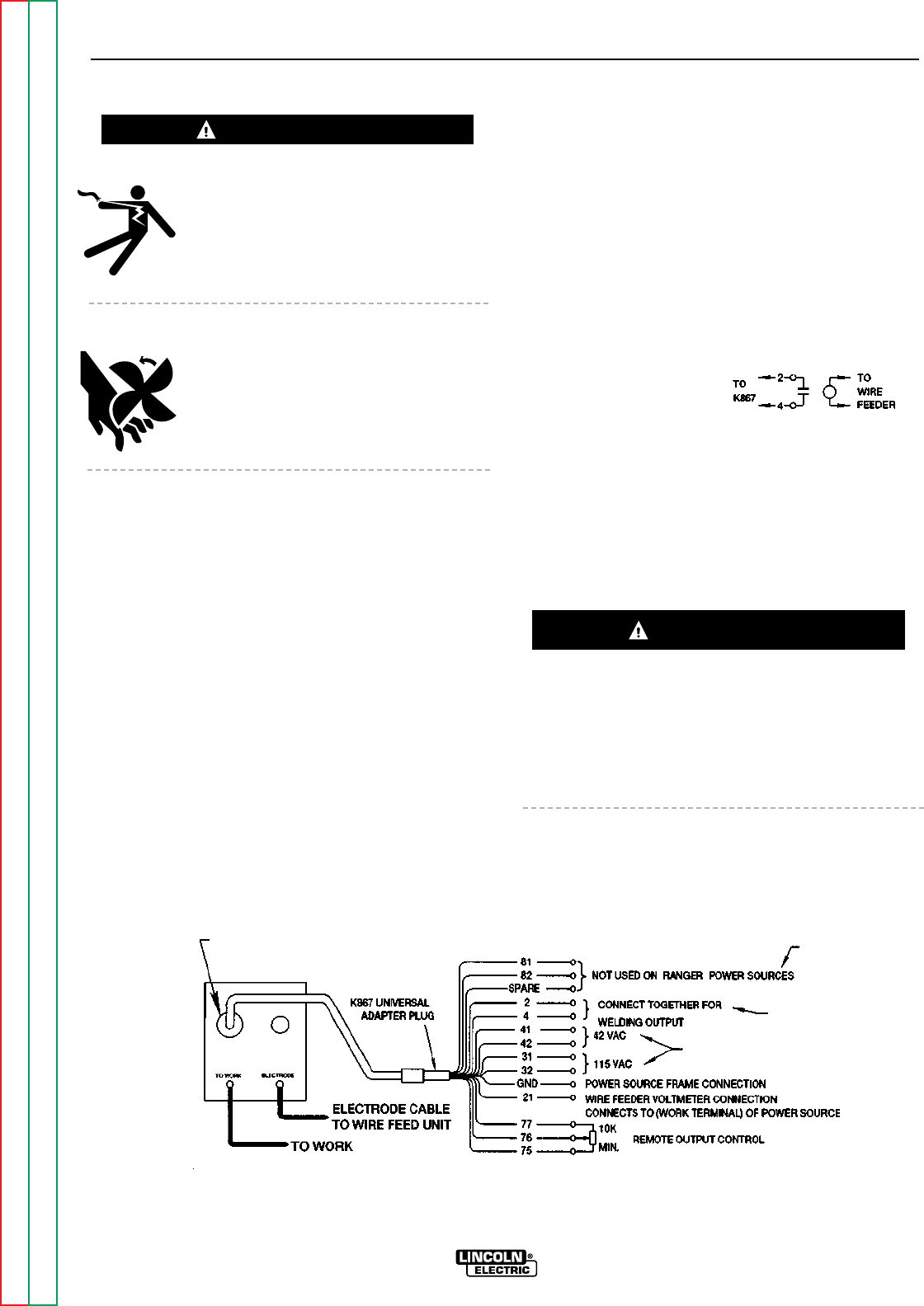
ELECTRIC SHOCK can kill.
• Do not operate with panels open.
• Disconnect NEGATIVE (-) BATTERY
LEAD before servicing.
• Do not touch electrically live parts.
MOVING PARTS can injure.
• Keep guards in place.
• Keep away from moving parts.
• Only qualified personnel should install,
use or service this equipment.
CONNECTION OF THE RANGER 9 TO
WIRE FEEDERS USING K867 UNIVERSAL
ADAPTER (SEE FIGURE C.1)
NOTE: When you use the RANGER 9 with non-
Lincoln Electric wire feeders or with cer-
tain earlier models of Lincoln wire feeders,
you will require the K867 Univeral Adapter.
The following discussion and connection
diagram explain in general how to make
the proper connections.
1. Shut the welder off.
2. Connect the electrode cable from the wire feeder to
the “ELECTRODE” terminal of the welder. Connect
the work cable to the “TO WORK” terminal of the
welder.
NOTE: Welding cable must be sized for current
and duty cycle of application.
3. Connect the K867 Universal Adapter to the 14 pin
amphenol of the RANGER 9 as shown in Figure F.1.
Make the proper connections for local or remote
control according to Figure C.1 and the following
NOTES, indicated on the figure:
A. These leads are not used for the RANGER 9.
Insulate each unused lead individually.
B. For wire feeders that return a signal for weld-
ing output, use an isolation relay to close leads
2 and 4.
C. Refer to the OPER-
ATION section of this manual for maximum
auxiliary current draw.
4. Set the welder “polarity” switch to the desired
polarity, either DC (-) or DC (+).
5. Set the “RANGE” switch to the “WIRE FEED” posi-
tion.
6. Place the “IDLER” switch in the “HIGH” position.
Any increase of the high idle engine RPM by changing
the governor setting or overriding the throttle linkage
will cause an increase in the AC auxiliary voltage. If
this voltage goes over 140 volts, wire feeder control
circuits may be damaged. The engine governor set-
ting is preset at the factory — do not adjust above
RPM specifications listed in this manual.
ACCESSORIES
C-4 C-4
RANGER 9 RANGER 9
Return to Section TOC Return to Section TOC Return to Section TOC Return to Section TOC
Return to Master TOC Return to Master TOC Return to Master TOC Return to Master TOC
FIGURE C.1 – RANGER 9/K867 UNIVERSAL ADAPTER CONNECTION DIAGRAM
CONNECTION OF LINCOLN ELECTRIC WIRE FEEDERS
WARNING
CAUTION
C
B
A
14 PIN
AMPHENOL
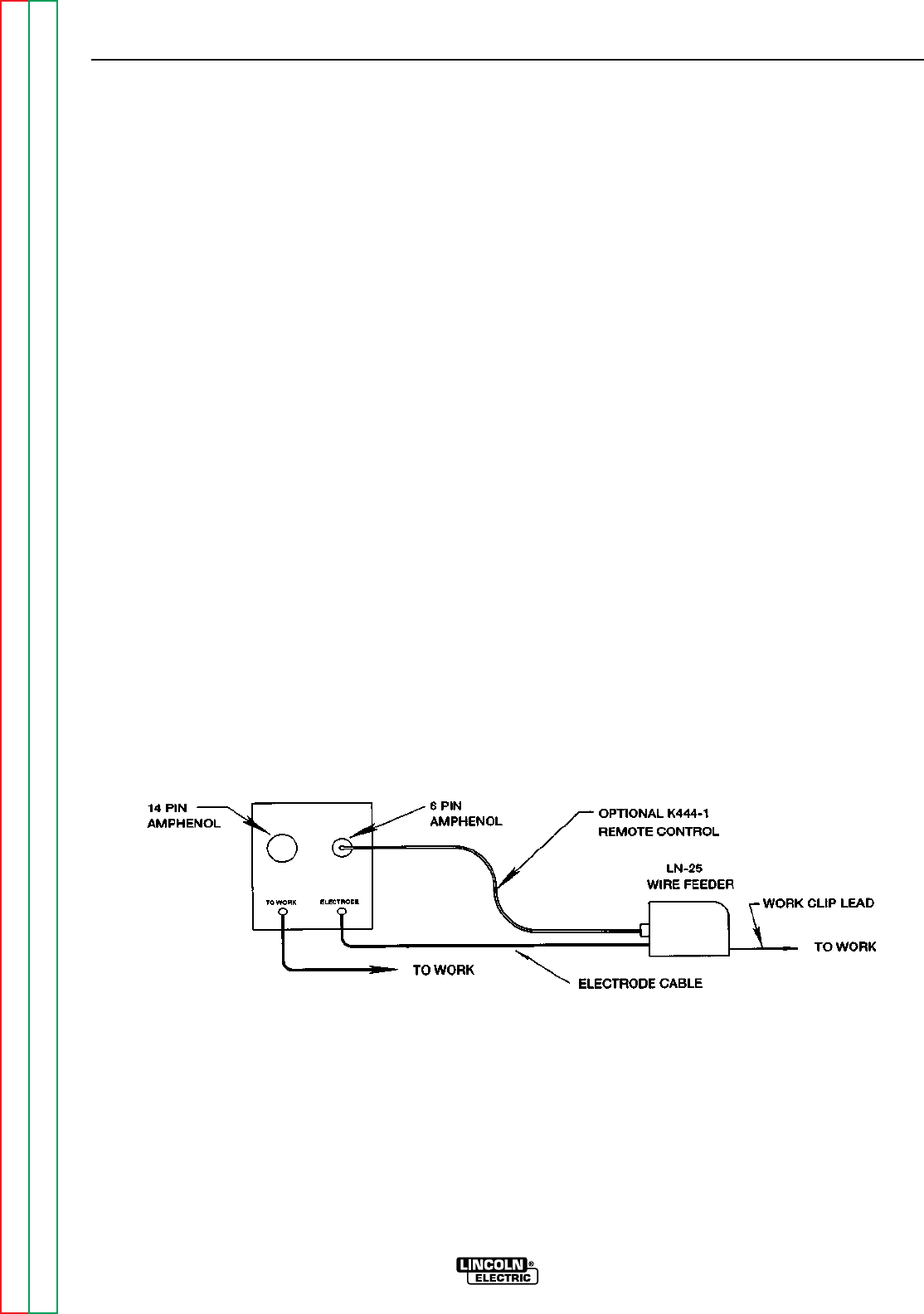
7. Place the WELDING TERMINALS switch in the
“REMOTELY CONTROLLED” position.
8. Adjust wire feed speed at the wire feeder and set
the welding voltage with the output “CONTROL” to
a CV (constant voltage) position at the welder.
NOTE: If optional remote control is used, place
the output control switch in the “CON-
TROL REMOTE” position.
CONNECTION OF THE LN-25 TO THE
RANGER 9 “ACROSS THE ARC”
(SEE FIGURE C.2.)
1. Shut the welder off.
2. Connect the electrode cable from the LN-25 to the
“ELECTRODE” terminal of the welder. Connect the
work cable to the “TO WORK” terminal of the
welder.
NOTE: Welding cable must be sized for current
and duty cycle of application.
3. Set the welder “polarity” switch to the desired
polarity, either DC (-) or DC (+).
4. Set the “RANGE” switch to the “WIRE FEED” posi-
tion.
5. Attach the single lead from the LN-25 control box
to the work using the spring clip on the end of the
lead. This is only a control lead — it carries no
welding current.
6. Place the “IDLER” switch in the “AUTO” position.
7. Place the WELDING TERMINALS switch in the
“ALWAYS ON” position.
8. Adjust wire feed speed at the LN-25 and adjust the
welding voltage with the output “CONTROL” at the
welder.
NOTE: If optional remote control is used, place
the output control switch in the “CON-
TROL REMOTE” position.
ACCESSORIES
C-5 C-5
RANGER 9 RANGER 9
Return to Section TOC Return to Section TOC Return to Section TOC Return to Section TOC
Return to Master TOC Return to Master TOC Return to Master TOC Return to Master TOC
FIGURE C.2 – RANGER 9/LN-25 ACROSS THE ARC CONNECTION DIAGRAM
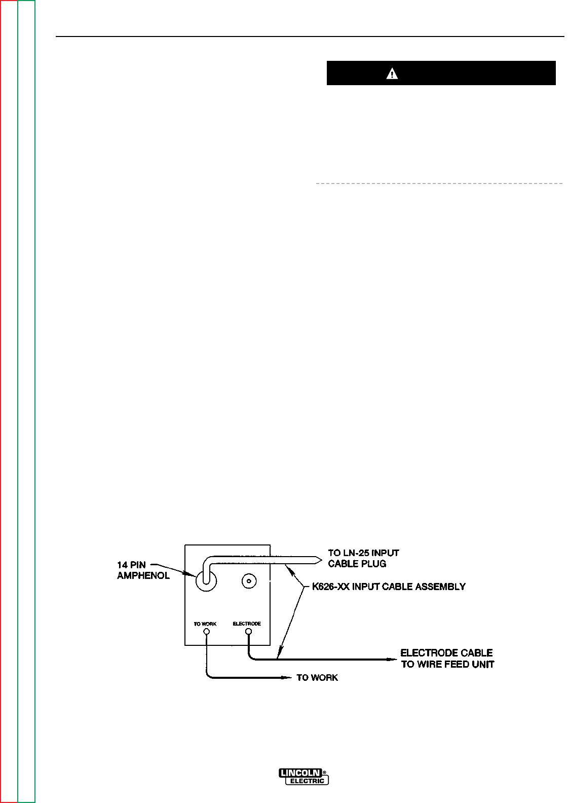
CONNECTION OF THE LN-25 TO THE
RANGER 9 WITH 42 VOLT REMOTE
OUTPUT CONTROL MODULE
(SEE FIGURE C.3.)
1. Shut the welder off.
2. Connect the electrode cable from the K626-XX
Input Cable Assembly to the “ELECTRODE” termi-
nal of the welder and to the LN-25 wire feeder.
Connect the work cable to the “TO WORK” termi-
nal of the welder.
NOTE: Welding cable must be sized for current
and duty cycle of application.
3. Connect the input cable from the K626-XX Input
Cable Assembly to the 14 pin amphenol on the
RANGER 9 and the input cable plug on the LN-25.
4. Set the welder “polarity” switch to the desired
polarity, either DC (-) or DC (+).
5. Set the “RANGE” switch to the “WIRE FEED” posi-
tion.
6. Place the “IDLER” switch to the “AUTO” or “HIGH”
position as desired.
Any increase of the high idle engine RPM by changing
the governor setting or overriding the throttle linkage
will cause an increase in the AC auxiliary voltage. If
this voltage goes over 140 volts, wire feeder control
circuits may be damaged. The engine governor set-
ting is preset at the factory — do not adjust above
RPM specifications listed in this manual.
7. Place the WELDING TERMINALS switch in the
“REMOTELY CONTROLLED” position.
8. Adjust wire feed speed at the LN-25 and set the
welding voltage with the output “CONTROL” at a
CV (constant voltage) position at the welder.
NOTE: If optional remote control is used, place
the output control switch in the “CON-
TROL REMOTE” position.
ACCESSORIES
C-6 C-6
RANGER 9 RANGER 9
Return to Section TOC Return to Section TOC Return to Section TOC Return to Section TOC
Return to Master TOC Return to Master TOC Return to Master TOC Return to Master TOC
FIGURE C.3
RANGER 9/LN-25 WITH 42 VOLT REMOTE OUTPUT CONTROL MODULE CONNECTION DIAGRAM
CAUTION
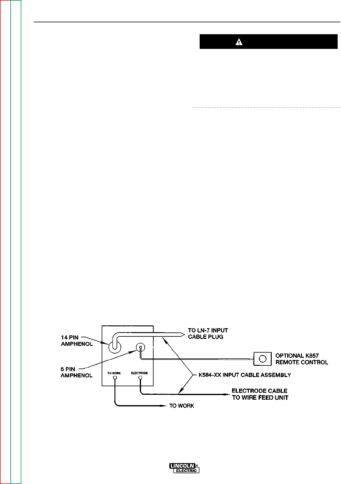
ACCESSORIES
C-7 C-7
RANGER 9 RANGER 9
Return to Section TOC Return to Section TOC Return to Section TOC Return to Section TOC
Return to Master TOC Return to Master TOC Return to Master TOC Return to Master TOC
CONNECTION OF THE LN-7 TO THE
RANGER 9 USING K584 INPUT CABLE
ASSEMBLY (SEE FIGURE C.4.)
NOTE: If your LN-7 comes equipped with a K291 or
K404 Input able, refer to CONNECTION OF
THE LN-7 Using K867 UNIVERSAL ADAPTER,
rather than this discussion, to connect your
RANGER 9 for wire feed welding.
1. Shut the welder off.
2. Connect the electrode cable from the K584-XX
Input Cable Assembly to the “ELECTRODE” termi-
nal of the welder and to the LN-7 wire feeder.
Connect the work cable to the “TO WORK” termi-
nal of the welder.
NOTE: Welding cable must be sized for current and
duty cycle of application.
3. Connect the input cable from the K584-XX Input
Cable Assembly to the 14 pin amphenol on the
RANGER 9 and the input cable plug on the LN-7.
4. Set the welder “polarity” switch to the desired
polarity, either DC (-) or DC (+).
5. Set the “RANGE” switch to the “WIRE FEED” posi-
tion.
6. Place the “IDLER” switch in the “HIGH” position.
Any increase of the high idle engine RPM by changing
the governor setting or overriding the throttle linkage
will cause an increase in the AC auxiliary voltage. If
this voltage goes over 140 volts, wire feeder control
circuits may be damaged. The engine governor set-
ting is preset at the factory — do not adjust above
RPM specifications listed in this manual.
7. Place the WELDING TERMINALS switch in the
“REMOTELY CONTROLLED” position.
8. Adjust wire feed speed at the LN-7 and set the
welding voltage with the output “CONTROL” at a
CV (constant voltage) position at the welder.
NOTE: If optional remote control is used, place the
output control switch in the “CONTROL
REMOTE” position.
FIGURE C.4
RANGER 9/LN-7 WITH K584 INPUT CABLE ASSEMBLY CONNECTION DIAGRAM
CAUTION
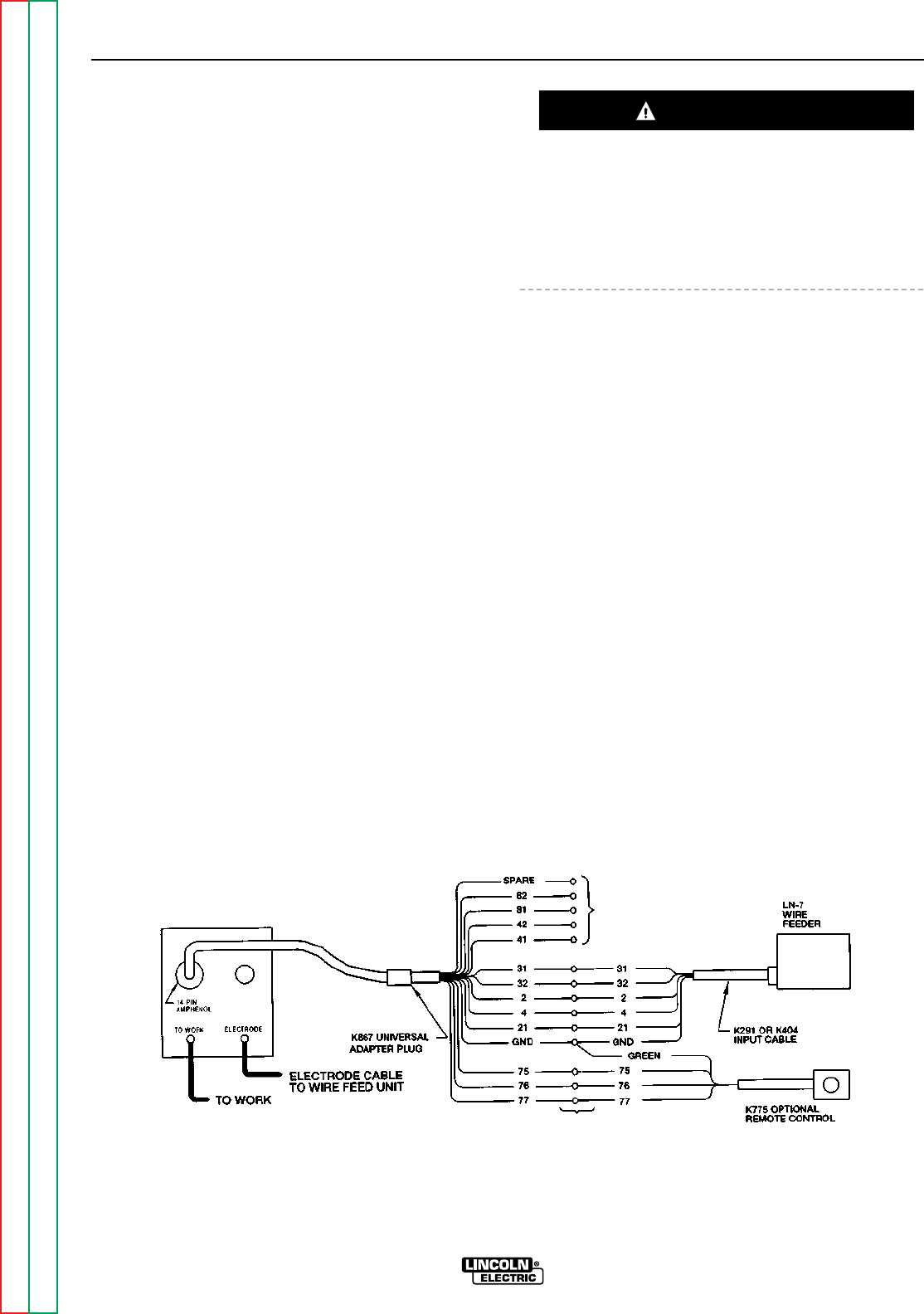
ACCESSORIES
C-8 C-8
RANGER 9 RANGER 9
Return to Section TOC Return to Section TOC Return to Section TOC Return to Section TOC
Return to Master TOC Return to Master TOC Return to Master TOC Return to Master TOC
CONNECTION OF THE LN-7 TO THE
RANGER 9 USING K867 UNIVERSAL
ADAPTER (SEE FIGURE C.5.)
1. Shut the welder off.
2. Connect the electrode cable from the LN-7 to the
“ELECTRODE” terminal of the welder. Connect the
work cable to the “TO WORK” terminal of the
welder.
NOTE: Welding cable must be sized for current and
duty cycle of application.
3. Connect the K867 Universal Adapter to the LN-7
wire feeder and the 14 pin amphenol of the
RANGER 9 as indicated in Figure C.5. Make the
proper connections for local or remote control
according Figure C.5 and the following NOTES,
indicated on the figure:
A. Insulate each unused lead individually.
B. Splice the leads and insulate.
4. Set the welder “polarity” switch to the desired
polarity, either DC (-) or DC (+).
5. Set the “RANGE” switch to the “WIRE FEED” posi-
tion.
6. Place the “IDLER” switch in the “HIGH” position.
Any increase of the high idle engine RPM by changing
the governor setting or overriding the throttle linkage
will cause an increase in the AC auxiliary voltage. If
this voltage goes over 140 volts, wire feeder control
circuits may be damaged. The engine governor set-
ting is preset at the factory — do not adjust above
RPM specifications listed in this manual.
7. Place the WELDING TERMINALS switch in the
“REMOTELY CONTROLLED” position.
8. Adjust wire feed speed at the LN-7 and set the
welding voltage with the output “CONTROL” to a
CV (constant voltage) position at the welder.
NOTE: If optional remote control is used, place the
output control switch in the “CONTROL
REMOTE” position.
FIGURE C.5
RANGER 9/LN-7 WITH K867 ADAPTER CONNECTION DIAGRAM
CAUTION
B
A
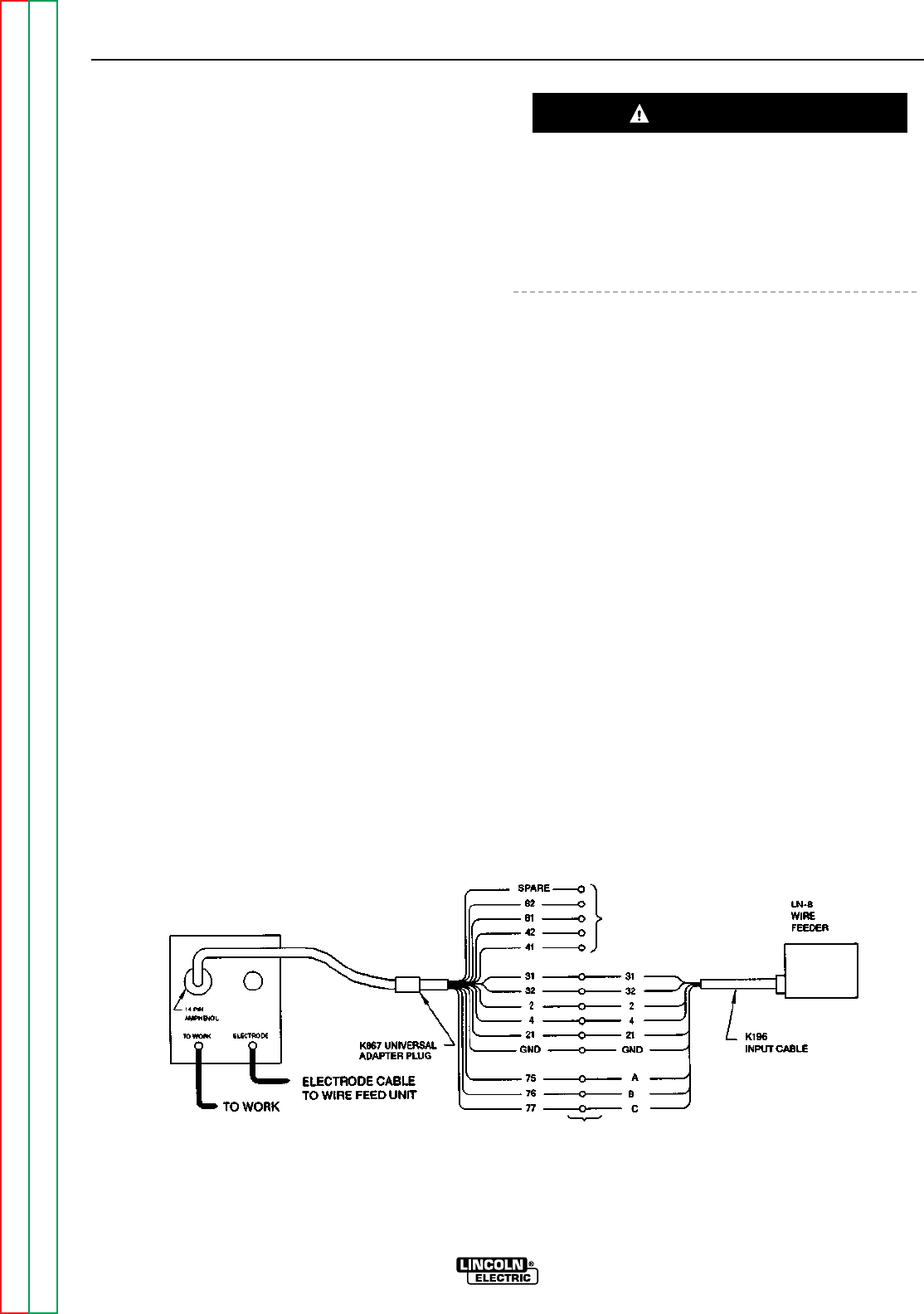
ACCESSORIES
C-9 C-9
RANGER 9 RANGER 9
Return to Section TOC Return to Section TOC Return to Section TOC Return to Section TOC
Return to Master TOC Return to Master TOC Return to Master TOC Return to Master TOC
CONNECTION OF THE LN-8 TO THE
RANGER 9 (SEE FIGURE C.6.)
1. Shut the welder off.
2. Connect the electrode cable from the LN-8 to the
“ELECTRODE” terminal of the welder. Connect the
work cable to the “TO WORK” terminal of the
welder.
NOTE: Welding cable must be sized for current and
duty cycle of application.
3. Connect the K867 Universal adapter to the LN-8
wire feeder and the 14 pin amphenol of the
RANGER 9 as indicated in Figure C.6. Make the
proper connections for local or remote control
according to Figure C.6 and the following NOTES,
indicated on the figure:
A. Insulate each unused lead individually.
B. Splice the leads and insulate.
4. Set the welder “polarity” switch to the desired
polarity, either DC (-) or DC (+).
5. Set the “RANGE” switch to the “WIRE FEED” posi-
tion.
6. Place the “IDLER” switch in the “˙HIGH” position.
Any increase of the high idle engine RPM by changing
the governor setting or overriding the throttle linkage
will cause an increase in the AC auxiliary voltage. If
this voltage goes over 140 volts, wire feeder control
circuits may be damaged. The engine governor set-
ting is preset at the factory — do not adjust above
RPM specifications listed in this manual.
7. Place the WELDING TERMINALS switch in the
“REMOTELY CONTROLLED” position.
8. Adjust wire feed speed at the LN-8 and set the
welding voltage with the output “CONTROL” to a
CV (constant voltage) position at the welder.
NOTE: If optional remote control is ued, place the
output control switch in the “CONTROL
REMOTE” position.
FIGURE C.6
RANGER 9/LN-8 CONNECTION DIAGRAM
CAUTION
A
B
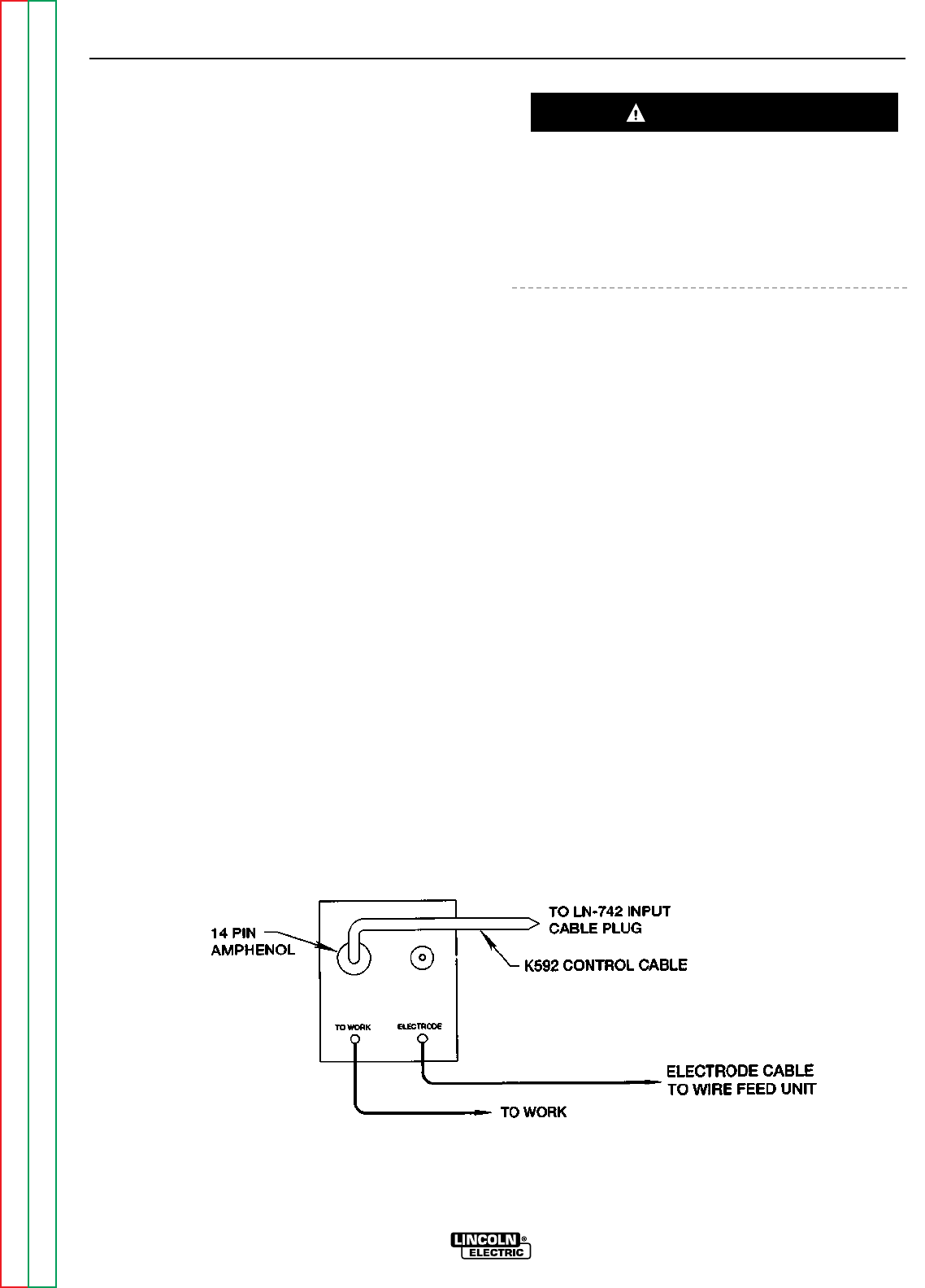
ACCESSORIES
C-10 C-10
RANGER 9 RANGER 9
Return to Section TOC Return to Section TOC Return to Section TOC Return to Section TOC
Return to Master TOC Return to Master TOC Return to Master TOC Return to Master TOC
CONNECTION OF THE LN-742 TO THE
RANGER 9 (SEE FIGURE C.7.)
1. Shut the welder off.
2. Connect the electrode cable from the LN-742 to
the “ELECTRODE” terminal of the welder. Connect
the work cable to the “TO WORK” terminal of hte
welder.
NOTE: Welding cable must be sized for current and
duty cycle of application.
3. Connect the K592 Control Cable to the 14 pin
amphenol on the RANGER 9 and the input cable
plug on the LN-742.
4. Set the welder “polarity” switch to the desired
polarity, either DC (-) or DC (+).
5. Set the “RANGE” switch to the “WIRE FEED” posi-
tion.
6. Place the “IDLER” switch in the “AUTO” or “HIGH”
position as desired.
Any increase of the high idle engine RPM by changing
the governor setting or overriding the throttle linkage
will cause an increase in the AC auxiliary volage. If this
voltage goes over 140 volts, wire feeder control cir-
cuits may be damaged. The engine governor setting
is preset at the factory — do not adjust above RPM
specifications listed in this manual.
7. Place the WELDING TERMINALS switch in the
“REMOTELY CONTROLLED” position.
8. Adjust wire feed speed at the LN-742 and set the
welding voltage with the output “CONTROL” to a
CV (constant voltage) position at the welder.
NOTE: If optional remote control is used, place the
output control switch in the “CONTROL
REMOTE” position.
FIGURE C.7
RANGER 9/LN-742 CONNECTION DIAGRAM
CAUTION
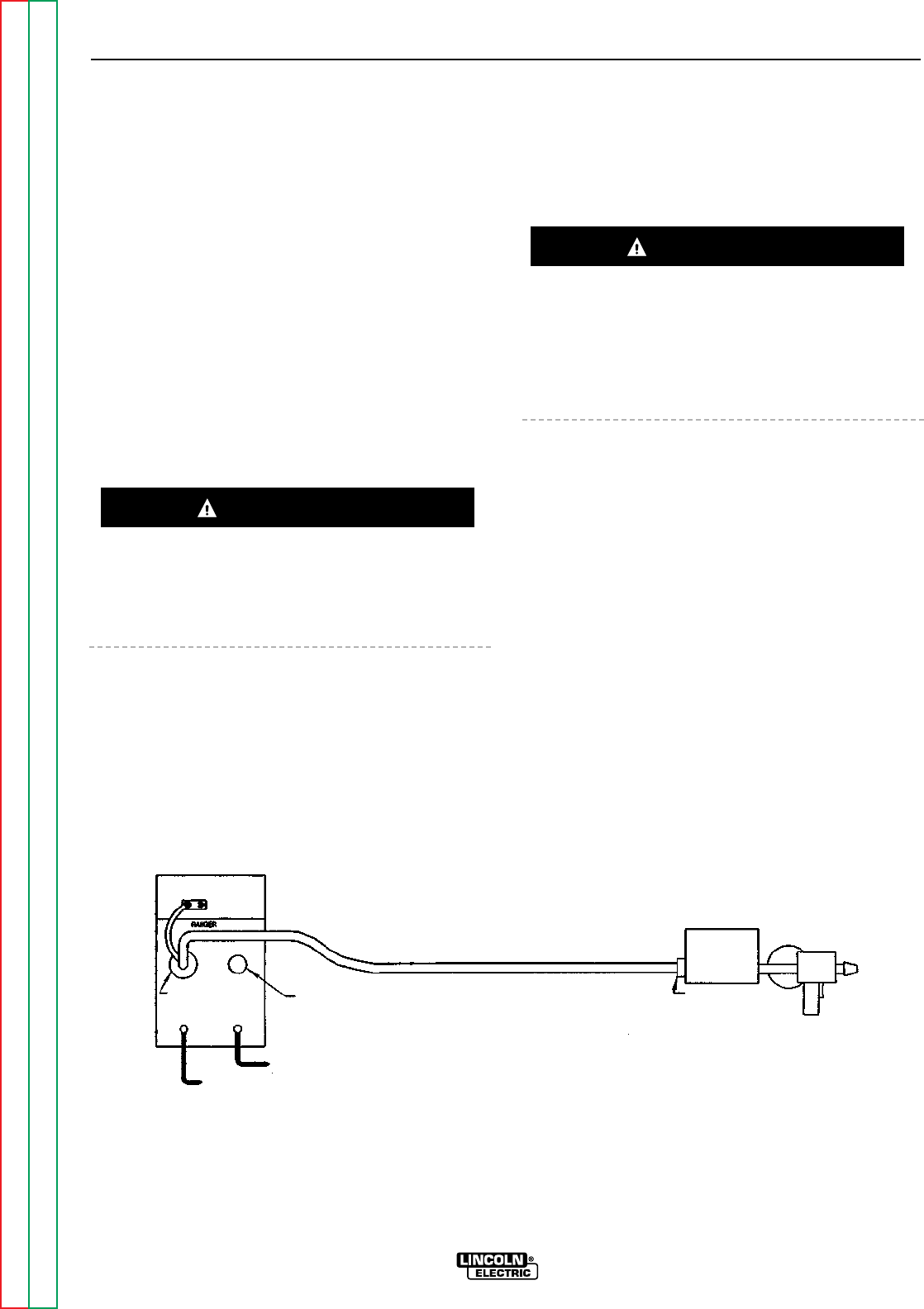
ACCESSORIES
C-11 C-11
RANGER 9 RANGER 9
Return to Section TOC Return to Section TOC Return to Section TOC Return to Section TOC
Return to Master TOC Return to Master TOC Return to Master TOC Return to Master TOC
CONNECTION OF THE K488 SG CON-
TROL MODULE AND K487 MAGNUM
SPOOL GUN TO THE RANGER 9
(SEE FIGURE C.8.)
1. Shut the welder off.
2. Connect the electrode cable from the SG Control
Module to the “ELECTRODE” terminal of the
welder. Connect the work cable to the “TO WORK”
terminal of the welder.
NOTE: Welding cable must be sized for current and
duty cycle of application.
3. Connect the K691-10 Input Cable to the SG
Control Module and the 14 pin amphenol of the
RANGER 9 as indicated in Figure C.8.
4. Set the slide switch on the SG Control Module to
the “Lincoln” position.
Be sure this switch is set to the “Lincoln” (contact clo-
sure) position before attempting to operate the SG
Control Module. Incorrect switch position could result
in damage to the SG Control Module and/or the
RANGER 9.
5. Set the welder “polarity” switch to the desired
polarity, either DC (-) or DC (+).
6. Set the “RANGE” switch to the “WIRE FEED” posi-
tion.
7. Place the “IDLER” switch in the “HIGH” position.
Any increase of the high idle engine RPM by changing
the governor setting or overriding the throttle linkage
will cause an increase in the AC auxiliary voltage. If
this voltage goes over 140 volts, wire feeder control
circuits may be damaged. The engine governor set-
ting is preset at the factory — do not adjust above
RPM specifications listed in this manual.
8. Place the WELDING TERMINALS switch in the
“REMOTELY CONTROLLED” position.
9. Adjust wire feed speed at the SG Control Module
and set the welding voltage with the output “CON-
TROL” to a CV (constant voltage) position at the
welder.
NOTE: If optional remote control is used, place the
output control switch in the “CONTROL
REMOTE” position.
FIGURE C.8
RANGER 9 AND 10LX/K691-10/K488/K487 SPOOL GUN CONNECTION DIAGRAM
CAUTION
CAUTION
115V RECEPTACLE
6 PIN REMOTE
RECEPTACLE
ELECTRODE CABLE
TO CONTROL MODULE
TO WORK
14 PIN WIRE FEEDER
RECEPTACLE
TO WORK ELECTRODE
K691-10
INPUT CABLE
K487-25
SPOOL GUN
K488 SG
CONTROL MODULE

Section D-1 Section D-1
RANGER 9 RANGER 9
TABLE OF CONTENTS
-MAINTENANCE-
Maintenance .........................................................................................................................Section D
Safety Precautions......................................................................................................................D-2
Routine and Periodic Maintenance ............................................................................................D-2
Engine Maintenance.............................................................................................................D-2
Change the Oil...............................................................................................................D-2
Change the Oil Filter......................................................................................................D-3
Fuel.................................................................................................................................D-3
Fuel Filter........................................................................................................................D-3
Air Cleaner......................................................................................................................D-4
Crankcase Breather .......................................................................................................D-5
Clean Engine, Clean Air Intake/Cooling Areas...............................................................D-5
Spark Plugs....................................................................................................................D-5
Clean Spark Arrester Screen .........................................................................................D-5
Remove Combustion Deposits......................................................................................D-5
Engine Maintenance Schedule ......................................................................................D-6
Engine Maintenance Parts.............................................................................................D-6
Battery Maintenance............................................................................................................D-7
Cleaning the Battery ......................................................................................................D-7
Checking Specific Gravity..............................................................................................D-7
Checking Electrolyte Level.............................................................................................D-7
Charging the Battery......................................................................................................D-7
Welder/Generator Maintenance...........................................................................................D-7
Storage...........................................................................................................................D-7
Cleaning.........................................................................................................................D-7
Brush Removal and Replacement.................................................................................D-7
Receptacles ...................................................................................................................D-8
Cable Connections.........................................................................................................D-8
Major Component Locations ...............................................................................................D-9
Return to Master TOC Return to Master TOC Return to Master TOC Return to Master TOC
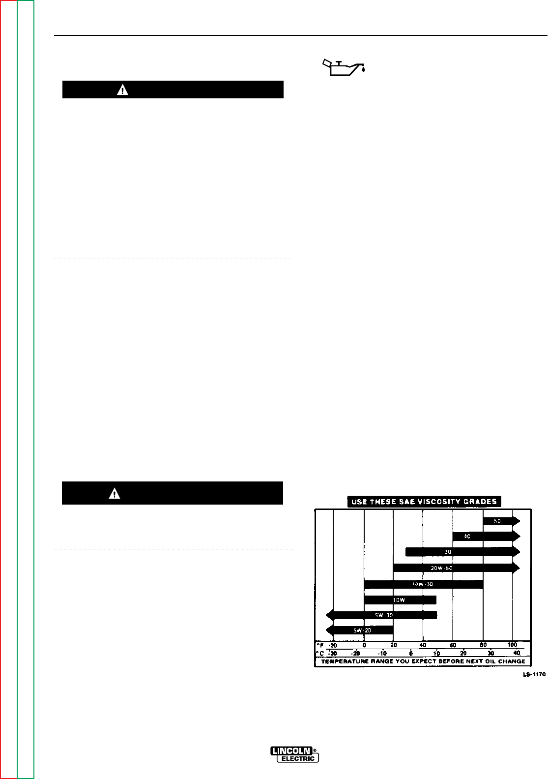
SAFETY PRECAUTIONS
• Have qualified personnel do all maintenance and
troubleshooting work.
• Turn the engine off before working inside the
machine.
• Remove guards only when necessary to perform
maintenance and replace them when the mainte-
nance requiring their removal is complete.
• If guards are missing from the machine, get replace-
ments from a Lincoln Distributor. See the EXPLOD-
ED VIEW AND PARTS LIST at the back of this man-
ual.
Read the Safety Precautions in the front of this manu-
al and in the instruction manual for the Onan gasoline
engine used with your machine before working on the
RANGER 9.
Keep all equipment safety guards, covers, and devices
in position and in good repair. Keep your hands, hair,
clothing, and tools away from the recoil housing, fans,
and all other moving parts when starting, operating, or
repairing this machine.
ROUTINE AND PERIODIC
MAINTENANCE
ENGINE MAINTENANCE
To prevent the engine from accidentally starting, dis-
connect the spark plug lead before servicing the
engine.
See Table D.2 for a summary of maintenance intervals
for the items listed below. Follow either the hourly or
the calendar intervals, whichever come first. More fre-
quent service may be required, depending on your
specific application and operating conditions. Table
D.3 shows engine maintenance replacement parts and
numbers.
OIL: Check the oil level after every 5
hours of operation or daily. BE SURE
TO MAINTAIN THE OIL LEVEL.
Change the oil the first time after 25 hours of opera-
tion. Then, under normal operating conditions,
change the oil as specified in Table D.3. If the engine
is operated under heavy load or in high ambient tem-
peratures, change the oil more frequently.
CHANGE THE OIL
Change the oil, while the engine is still warm, as fol-
lows:
1. Drain the oil from the drain plug located on the
engine bottom, as shown in Figure D.1. For the
RANGER 9, a short pipe nipple has been installed
to extend the drain plug access for easier service-
ability.
2. Replace the cap on the drain extension and tighten
it securely.
3. Remove the oil fill cap and add oil until the level
reaches the full mark on the dipstick. Use high
quality detergent oil of API service class SF, SF/CC,
or SF/CD . See Table D.1 for recommended vis-
cosity grades. Straight weight oils are recom-
mended for severe duty use and at temperatures
above 32°F (0°C) for minimum oil consumption.
Always check the level with the dipstick before
adding more oil.
4. Reinstall the oil fill cap and dipstick.
TABLE D.1
RECOMMENDED OIL VISCOSITY GRADES
MAINTENANCE
D-2 D-2
RANGER 9 RANGER 9
Return to Section TOC Return to Section TOC Return to Section TOC Return to Section TOC
Return to Master TOC Return to Master TOC Return to Master TOC Return to Master TOC
WARNING
CAUTION
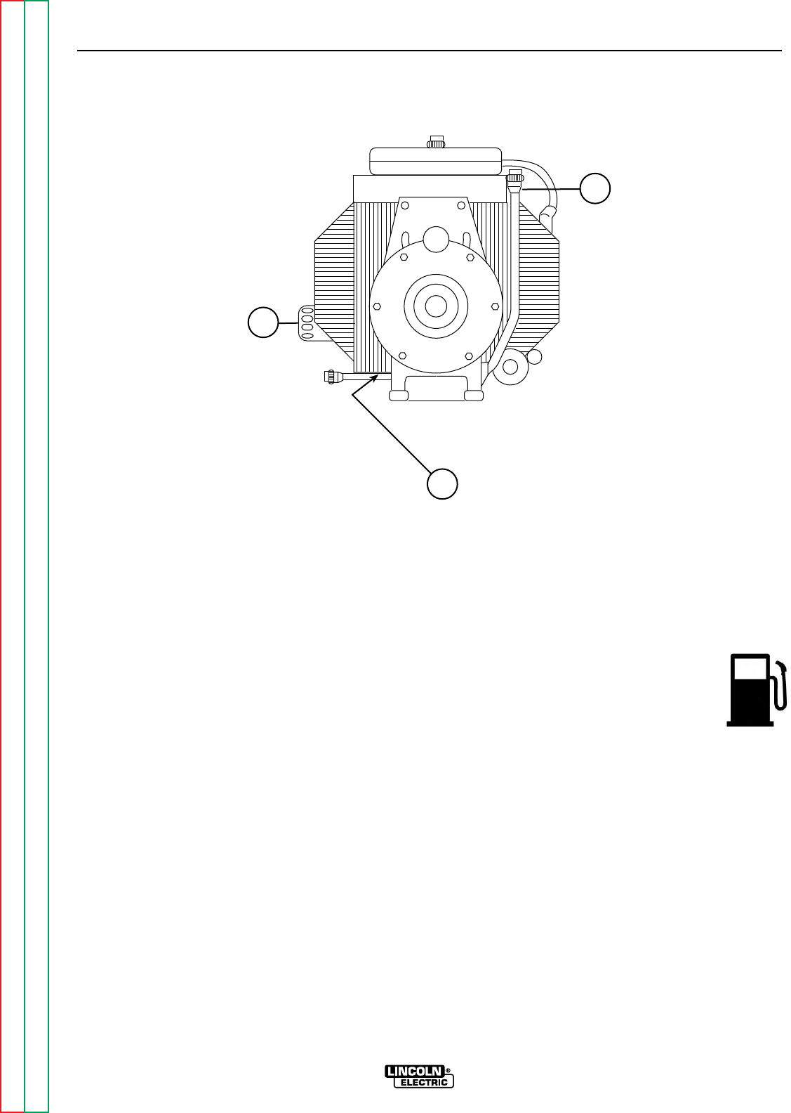
CHANGE THE OIL FILTER
Change the oil filter the first time after 25 hours of
operation. Then, under normal operating conditions,
change the oil filter after every other oil change. If the
engine is operated under heavy load or in high ambi-
ent temperatures, change the oil filter more frequently.
See Table D.3 for recommended maintenance inter-
vals.
Change the oil filter as follows:
1. Drain the oil from the engine and allow the oil filter
to drain.
2. Remove the old filter (spin it off) and discard it.
Wipe off the filter mounting surface and adapter.
3. Apply a thin coat of new oil to the rubber gasket on
the new oil filter.
4. Spin the new filter onto the mounting adapter until
the gasket just touches the mounting surface, then
turn it down another 1/2 to 3/4 turn. Do not over-
tighten the new filter.
5. Refill the engine with the proper amount and type of
oil as described in the Change the Oil section,
above. Start the engine and check for leaks around
the filter element. Correct any leaks (usually by
retightening the filter, but only enough to stop leaks)
before placing the RANGER 9 back in service.
6. If there are no leaks, stop the engine and recheck
the oil level. If necessary, add oil to bring the level
up to the FULL mark, but do not overfill.
FUEL: At the end of each day’s use, refill the
fuel tank to minimize moisture condensation
and dirt contamination in the fuel line. Do
not overfill; leave room for the fuel to
expand.
Use only fresh, unleaded gasoline with octane rating
87 or higher. Gasoline/alcohol blends are approved for
use with your engine as long as the blend does not
exceed 10% ethyl alcohol by volume. Other gaso-
line/alcohol blends are not approved, and their use
may damage fuel system and engine parts.
FUEL FILTER: Your engine may be equipped with an
in-line fuel filter. Inspect the fuel filter periodically and
replace it if it appears dirty.
MAINTENANCE
D-3 D-3
RANGER 9 RANGER 9
Return to Section TOC Return to Section TOC Return to Section TOC Return to Section TOC
Return to Master TOC Return to Master TOC Return to Master TOC Return to Master TOC
3
1
2
1. DIPSTICK/OIL FILL
2. OIL DRAIN PLUG 3. OIL FILTER
FIGURE D.1 – OIL DRAIN AND REFILL LOCATION
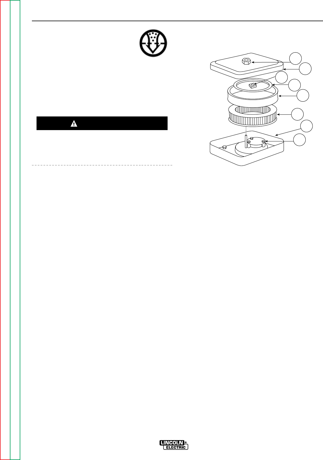
AIR CLEANER: Your air cleaner may
have only the paper element, or it may
have the cartridge and a foam preclean-
er. If it has the precleaner, service the
element every 50 hours and the pre-
cleaner every 25 hours. If the air cleaner doesn’t have
the precleaner, service the element every 25 hours.
Under dusty conditions, service more often. Check
the air cleaner every day or before starting the engine
for any buildup of dirt, debris, or loose or damaged
components.
DO NOT OIL THE ELEMENT OR USE PRESSURIZED
AIR TO CLEAN THE ELEMENT. DO NOT WASH THE
ELEMENT.
Remove the air cleaner cover:
1. Remove the cover nut, cover, element cover nut
and element cover, Figure D.2.
2. Carefully remove the foam precleaner, if equipped,
from the element.
To service the precleaner:
1. Wash in liquid detergent and water.
2. Squeeze dry in a clean cloth.
3. Saturate in clean engine oil.
4. Squeeze in a clean, absorbent cloth to remove all
excess oil.
To service the element:
1. Tap gently on a clean surface.
2. Inspect all air cleaner components, including cover
and base components, for wear or damage. Check
that all sealing surfaces are in good condition.
3. Replace with a new element if the old one is very
dirty, bent, or otherwise damaged.
Carefully place the precleaner back over the element
and reinstall and secure the air cleaner cover compo-
nents.
FIGURE D.2 - AIR CLEANER
COMPONENTS, ONAN ENGINE
1. COVER NUT
2. COVER
2A. ELEMENT COVER NUT
3. ELEMENT COVER
4. ELEMENT PRECLEANER
5. ELEMENT
6. BASE
7. AIR DEFLECTOR PLATE
MAINTENANCE
D-4 D-4
RANGER 9 RANGER 9
Return to Section TOC Return to Section TOC Return to Section TOC Return to Section TOC
Return to Master TOC Return to Master TOC Return to Master TOC Return to Master TOC
CAUTION
2A 3
2
1
4
56
7
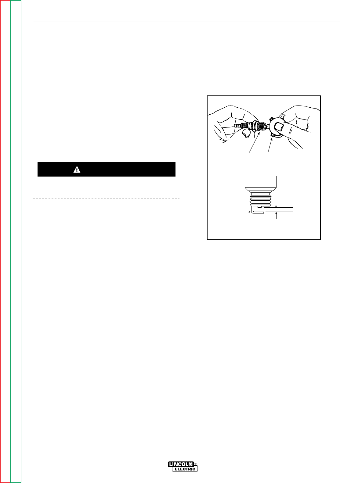
CRANKCASE BREATHER: The Onan engine is
equipped with a crankcase breather that prevents
pressure from building up inside the crankcase, pre-
vents moisture contamination from moisture, gasoline
vapors, or combustion vapors. If the breather valve
becomes sticky, it can cause oil leaks, oil consump-
tion, rough idle, reduced power, and sludge and var-
nish buildup in the engine.
The breather cannot be serviced. However, it should
be periodically inspected and replaced if cracked or
broken, or if the crankcase becomes pressurized.
Evidence of high pressure includes oil leaks at the
seals or excessive oil in the air cleaner housing.
CLEAN ENGINE: Remove dirt and debris with a cloth
or brush. Do not clean with a forceful spray of water.
Water might contaminate the fuel system.
Periodically clean the muffler area to remove com-
bustible debris.
CLEAN AIR INTAKE/COOLING AREAS: To ensure
proper cooling, make sure the grass screen, cooling
fins, and other external engine surfaces are always
kept clean. This will prevent overspeeding, overheat-
ing, and engine damage due to dirt or debris buildup.
Every 50 operating hours or as often as necessary,
remove the blower housing and other cooling shrouds.
Clean the cooling fins and external surfaces as neces-
sary. Make sure to replace all the cooling shrouds.
Running the engine without the cooling shrouds will
cause damage to the engine from overheating.
CLEAN OR REPLACE SPARK PLUGS: Clean or
replace the spark plugs after every 500 hours of oper-
ation as follows.
1. Before removing the plugs, clean the base area to
keep dirt from falling into the engine through the
plug hole.
2. Remove and inspect the plugs. Plugs showing
signs of fouling or electrode wear should be
replaced. Do not blast the spark plugs clean with
an abrasive cleaning device. Clean the plugs by
scraping or by using a wire brush. Wash the plugs
with a commercial solvent.
3. After cleaning or when installing a new spark plug,
set the terminal gap with a feeler gauge. See
Figure D.3.
Gap Specifications: 0.025 inch (.64 mm)
FIGURE D.3 - SET SPARK PLUG GAP
CLEAN SPARK ARRESTER SCREEN: If the muffler
has the optional spark arrester, remove it every 50
hours or once a year, whichever comes first, and
inspect it. Clean the arrester. Replace it if you find any
damage.
REMOVE COMBUSTION DEPOSITS: Combustion
deposits (carbon) can form on the cylinder, cylinder
head, top of the piston, and around the valves over
time, depending on engine loading conditions, type of
fuel used, and other factors that affect engine perfor-
mance. Consult your local Onan engine distributor for
recommended cleaning intervals and procedures.
MAINTENANCE
D-5 D-5
RANGER 9 RANGER 9
Return to Section TOC Return to Section TOC Return to Section TOC Return to Section TOC
Return to Master TOC Return to Master TOC Return to Master TOC Return to Master TOC
Ground
Electrode
Wire Gauge
Spark Plug
Gap: Onan - 0.025 inch (.64 mm)
Kohler - 0.040 inch (1.02 mm)
CAUTION
Gap: 0.025 inch (.64 mm)

MAINTENANCE
D-6 D-6
RANGER 9 RANGER 9
Return to Section TOC Return to Section TOC Return to Section TOC Return to Section TOC
Return to Master TOC Return to Master TOC Return to Master TOC Return to Master TOC
TABLE D.2
ONAN ENGINE MAINTENANCE SCHEDULE
FREQUENCY MAINTENANCE REQUIRED
Daily or Before
Starting Engine • Fill fuel tank.
• Check oil level.
• Check air cleaner for dirty2, loose, or damaged parts.
• Check air intake and cooling areas, clean as necessary2.
Every 25 Hours • Service precleaner element2.
Every 50 Hours • Service air cleaner element2.
• Change oil1.
Every 100 Hours • Check spark plug condition and gap.
• Remove cooling shrouds and clean cooling areas2.
• Change oil filter.
Note 1: Change oil every 25 hours when operating under heavy load in high ambient temperatures.
Note 2: Clean more often under dusty conditions or when airborne debris is present.
TABLE D.3
ENGINE MAINTENANCE PARTS
Part Part Number - Onan
Oil Filter Onan 122-0645
FRAM PH3614
Fuel Filter Onan 149-2005
FRAM G1
Air Cleaner Element Onan 140-2628-01
FRAM CA140PL
Air Cleaner Precleaner Onan 140-1496
Spark Plugs Onan 167-0263
Champion®RS14YC
(.025” gap - .64 mm)
BATTERY MAINTENANCE
GASES FROM BATTERY can explode.
• Keep sparks, flame, and cigarettes
away from battery.
To prevent EXPLOSION when:
• INSTALLING A NEW BATTERY - Disconnect the
negative cable from the old battery first and connect
to the new battery last.
• CONNECTING A BATTERY CHARGER -
Remove the battery from the welder by
disconnecting the negative cable first,
then the positive cable and battery
clamp. When reinstalling, connect the
negative cable last. Keep the area well
ventilated.
• USING A BOOSTER - Connect the positive lead to
the battery first, then connect the negative lead to
the engine foot.
BATTERY ACID CAN BURN EYES AND
SKIN.
• Wear gloves and eye protection and be
careful when working near a battery.
Follow the instructions printed on the
battery.
CLEANING THE BATTERY
Keep the battery clean by wiping it with a damp cloth
when dirty. If the terminals appear corroded, discon-
nect the battery cables and wash the terminals with an
ammonia solution or a solution of 1/4 pound (0.113 kg)
of baking soda and 1 quart (0.946 l) of water. Be sure
the battery vent plugs (if equipped) are tight so that
none of the solution enters the cells.
After cleaning, flush the outside of the battery, the bat-
tery compartment, and surrounding areas with clear
water. Coat the battery terminals lightly with petrole-
um jelly or a non-conductive grease to retard corro-
sion.
Keep the battery clean and dry. Moisture accumula-
tion on the battery can lead to more rapid discharge
and early battery failure.
CHECKING SPECIFIC GRAVITY
Check each battery cell with a hydrometer. A fully
charged battery will have a specific gravity of 1.260.
Charge the battery if the reading is below 1.215.
NOTE: Correct the specific gravity reading by adding
four gravity points (0.004) for every five degrees the
electrolyte temperature is above 80 degrees F (27
degrees (C). Subtract four gravity points (9.004) for
every five degrees the electrolyte temperature is below
80 degrees F (27 degrees C).
CHECKING ELECTROLYTE LEVEL
If battery cells are low, fill them to the neck of the filler
hole with distilled water and recharge. If one cell is
low, check for leaks.
CHARGING THE BATTERY
When you charge, jump, replace, or otherwise connect
battery cables to the battery, be sure the polarity is
correct. Improper polarity can damage the charging
circuit. The RANGER 9 positive (+) battery terminal
has a red terminal cover.
If you need to charge the battery with an external
charger, disconnect the negative cable first, then the
positive cable before you attach the charger leads.
After the battery is charged, reconnect the positive
battery cable first and the negative cable last. Failure
to do so can result in damage to the internal charger
components.
Follow the instructions of the battery charger manu-
facturer for proper charger settings and charging time.
WELDER/GENERATOR
MAINTENANCE
STORAGE: Store the RANGER 9 in clean, dry, pro-
tected areas.
CLEANING: Blow out the generator and controls peri-
odically with low pressure air. Do this at least once a
week in particularly dirty areas.
BRUSH REMOVAL AND REPLACEMENT: It’s normal
for the brushes and slip rings to wear and darken
slightly. Inspect the brushes when a generator over-
haul is necessary. Remove the brushes and clean the
slip rings with fine emery paper. Refer to the “Brush
Removal and Replacement” procedure in the Trouble-
shooting and Repair section of this manual.
Do not attempt to polish slip rings while the engine is
running.
MAINTENANCE
D-7 D-7
RANGER 9 RANGER 9
Return to Section TOC Return to Section TOC Return to Section TOC Return to Section TOC
Return to Master TOC Return to Master TOC Return to Master TOC Return to Master TOC
WARNING
CAUTION
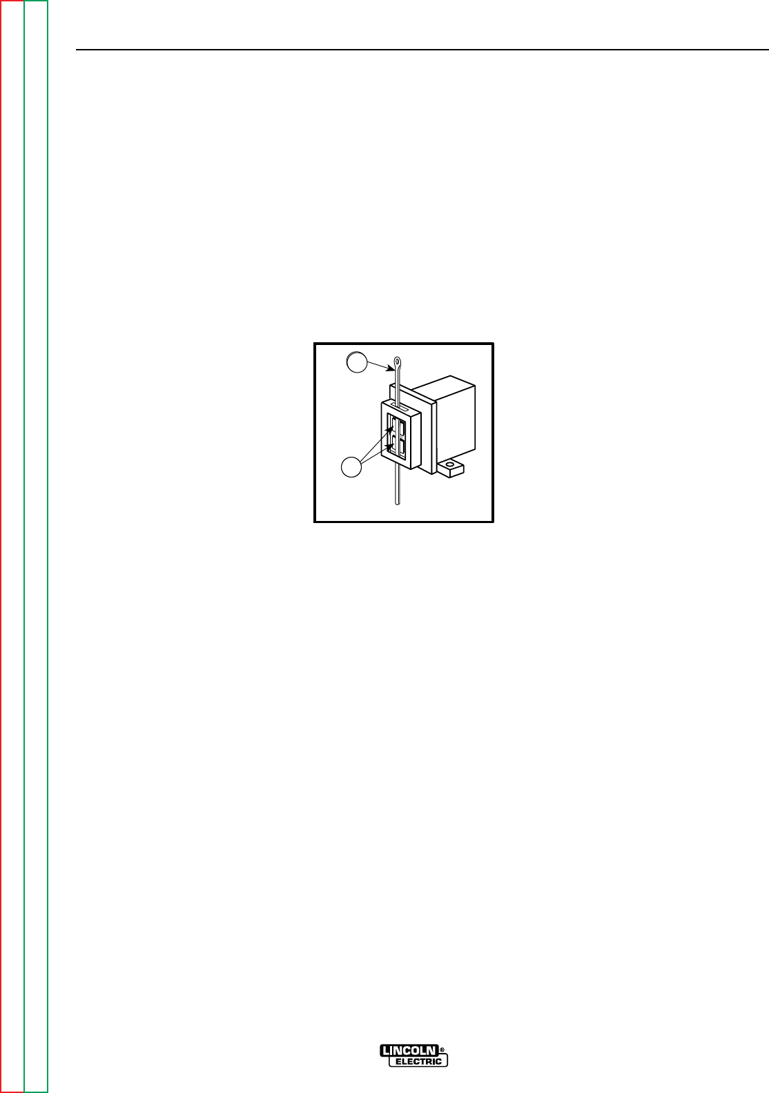
To reinstall the brushes, press them upward and slide
a cable tie or wooden stick through the brush holder
tabs. See Figure D.4. Install the brush holder into
position and secure with the screws previously
removed. Remove the cable tie or wooden stick and
the brushes will seat onto the slip rings.
RECEPTACLES: Keep the electrical receptacles in
good condition. Remove any dirt, oil, or other debris
from their surfaces and holes.
CABLE CONNECTIONS: Check the welding cable
connections at the weld output terminals often. Be
sure that the connections are always firm.
MAINTENANCE
D-8 D-8
RANGER 9 RANGER 9
Return to Section TOC Return to Section TOC Return to Section TOC Return to Section TOC
Return to Master TOC Return to Master TOC Return to Master TOC Return to Master TOC
FIGURE D.4 - BRUSH REMOVAL AND REPLACEMENT
1. BRUSHES
2. CABLE TIE
5
6
2
1
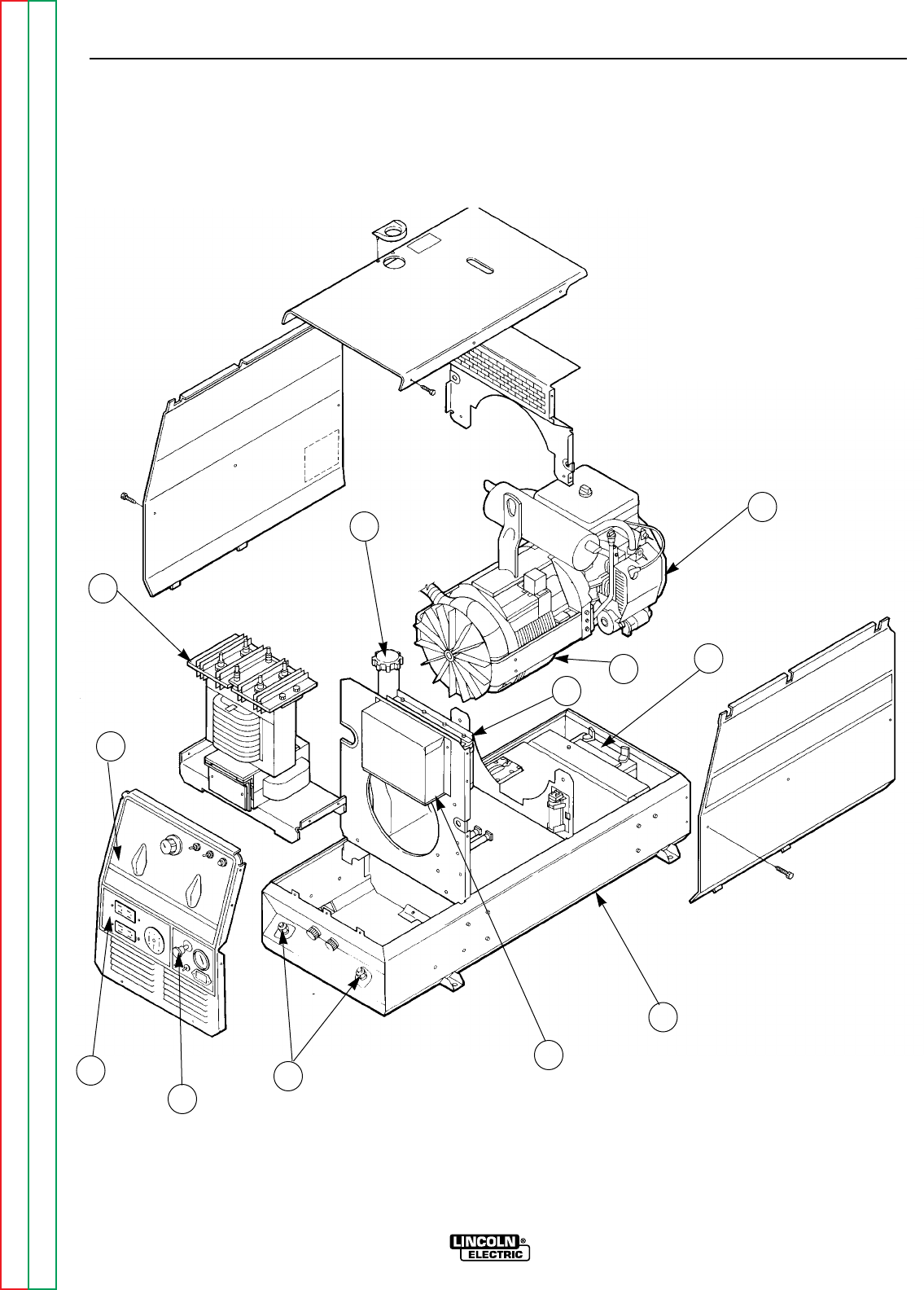
MAINTENANCE
D-9 D-9
RANGER 9 RANGER 9
Return to Section TOC Return to Section TOC Return to Section TOC Return to Section TOC
Return to Master TOC Return to Master TOC Return to Master TOC Return to Master TOC
FIGURE D.6 - MAJOR COMPONENT LOCATIONS
7
8
12
9
10
11
1
2
3
4
5
6
1. OUTPUT TERMINALS (LOCATION)
2. ENGINE CONTROLS
3. AUXILIARY POWER RECEPTACLES
4. OUTPUT PANEL CONTROL
5. OUTPUT RECTIFIER/REACTOR/CHOKE
6. FUEL TANK FILL
7. GASOLINE ENGINE
8. ROTOR/STATOR ASSEMBLY
9. BATTERY
10. MACHINE BASE
11. P.C. BOARD COVER
12. CAPACITOR BANK
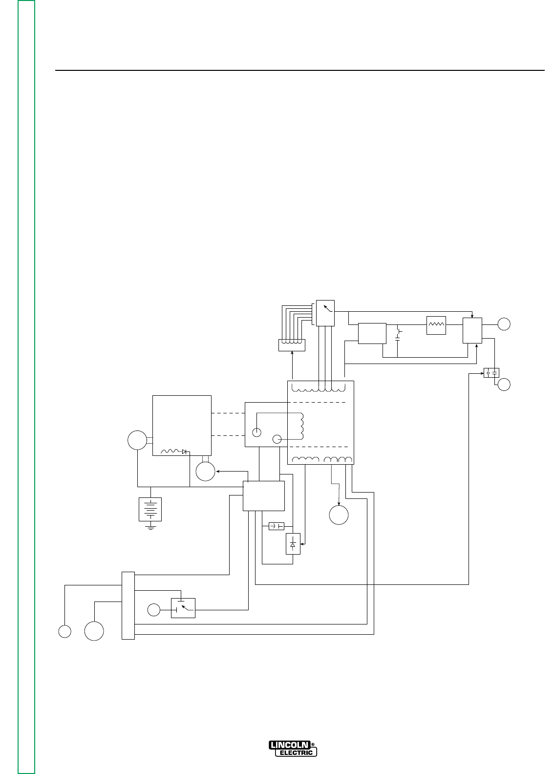
Section E-1 Section E-1
RANGER 9 RANGER 9
Theory of Operation .............................................................................................................Section E
Battery, Starter, Engine, Rotor,
Stator, and Idler Solenoid...................................................................................................E-2
Rotor Field Feedback, Auxiliary, and Wire Feeder Power.....................................................E-3
Weld Winding, Reactor, and Range Switch...........................................................................E-4
Output Bridge, Capacitors, Choke, Polarity Switch, Contactor and Output Terminals........E-5
TABLE OF CONTENTS
-THEORY OF OPERATION SECTION-
WORK
TERMINAL
OUTPUT
CONTACTOR
ELECTRODE
TERMINAL
POLARITY
SWITCH
CHOKE
PART OF
RANGE
SWITCH
CAPACITORS
OUTPUT
RECTIFIER
BRIDGE
AC
AC
RANGE
SWITCH
REACTOR
STATOR
ROTOR
MECHANICAL
ROTATION
ROTOR
SLIP
RINGS
IDLER
SOLENOID
ENGINE
STARTER
BATTERY
FLYWHEEL
ALTERNATOR
PRINTER
CIRCUT
BOARD
FIELD
CAPACITOR
115 & 230VAC
RECEPTACLES
FIELD
BRIDGE
CONTACTOR CLOSURE
BY-PASS
BOARD CONTACTOR CLOSURE
REMOTE
SWITCH
OUTPUT
CONTROL
6 PIN
AMPHENOL 14 PIN
AMPHENOL
115VAC
42VAC
FIGURE E.1 – RANGER 9 BLOCK LOGIC DIAGRAM
Return to Master TOC Return to Master TOC Return to Master TOC Return to Master TOC
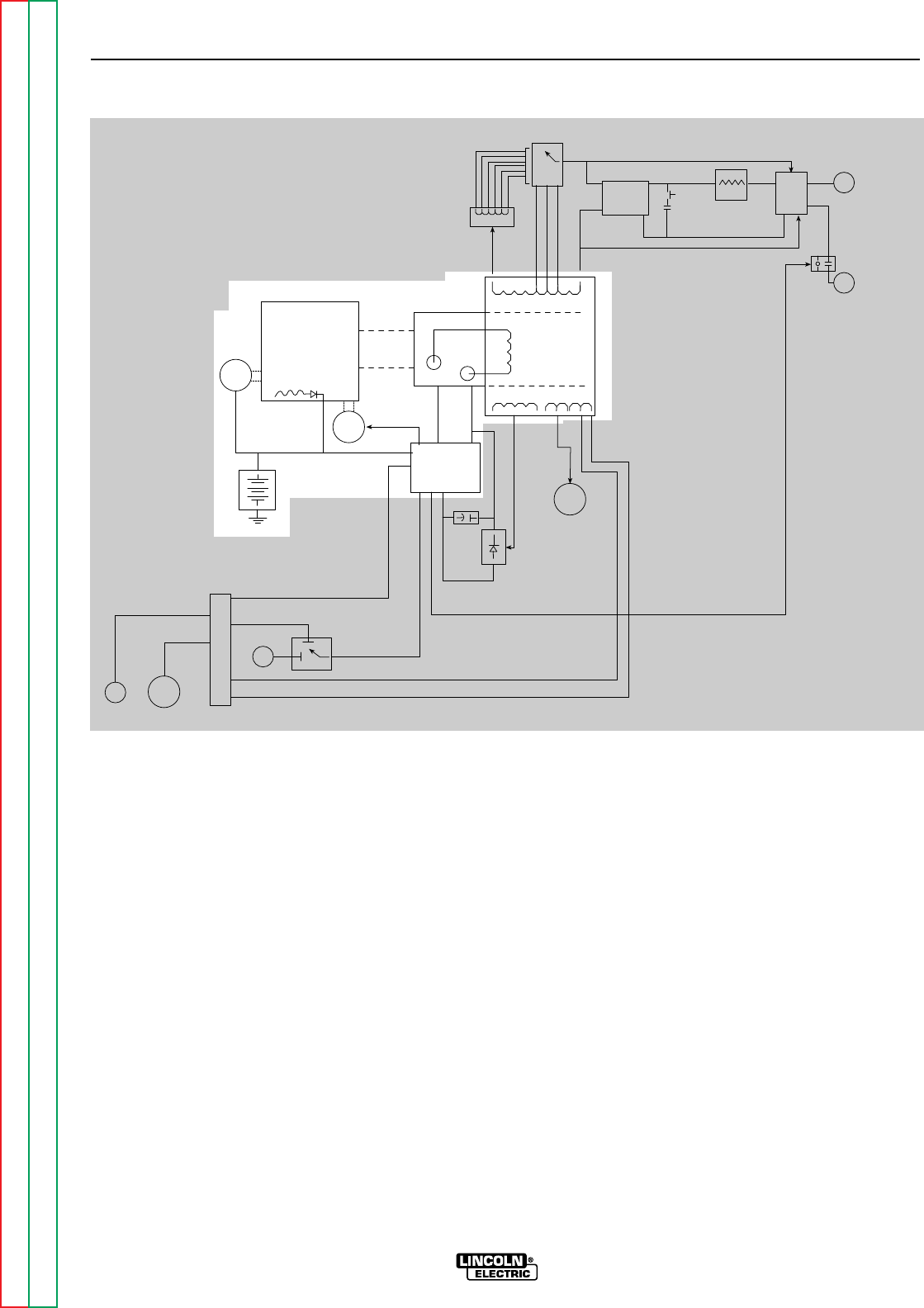
BATTERY, STARTER, ENGINE,
ROTOR, STATOR, AND IDLER
SOLENOID
The 12VDC battery powers the starter motor. When
the engine is started and running, the battery circuit
voltage is fed, through the printed circuit board, to the
rotating field coil in the rotor via a brush and slip ring
configuration. This excitation (“flashing”) voltage mag-
netizes the rotor lamination. The rotor is mechanically
coupled to the engine. This rotating magnet induces a
voltage in the stationary windings of the main alterna-
tor (stator). Four separate and isolated windings are
incorporated in the stator lamination assembly. Each
winding set has a different number of turns producing
different magnitudes of AC output voltages. The four
windings are the weld winding, the auxiliary power
winding, the field feedback winding, and the auxiliary
power winding for wire feeders. The field feedback
winding provides rotor current during machine opera-
tion. The output of the RANGER 9 is dependent on
two criteria: the engine RPM and the amount of current
in the rotor winding.
The flywheel alternator, located on the engine, supplies
“charging” current for the battery circuit. The battery
circuit provides power for the printed circuit board and
also for the idler solenoid. The idler solenoid is
mechanically connected to the engine throttle linkage.
If no current is being drawn from the RANGER 9, the
printed circuit board activates the idler solenoid, which
then brings the engine to a low idle state. When out-
put current is sensed, either weld or auxiliary, the print-
ed circuit board deactivates the idler solenoid, and the
engine returns to high RPM.
THEORY OF OPERATION
E-2 E-2
RANGER 9 RANGER 9
Return to Section TOC Return to Section TOC Return to Section TOC Return to Section TOC
Return to Master TOC Return to Master TOC Return to Master TOC Return to Master TOC
WORK
TERMINAL
OUTPUT
CONTACTOR
ELECTRODE
TERMINAL
POLARITY
SWITCH
CHOKE
PART OF
RANGE
SWITCH
CAPACITORS
OUTPUT
RECTIFIER
BRIDGE
AC
AC
RANGE
SWITCH
REACTOR
STATOR
ROTOR
MECHANICAL
ROTATION
ROTOR
SLIP
RINGS
IDLER
SOLENOID
ENGINE
STARTER
BATTERY
FLYWHEEL
ALTERNATOR
PRINTER
CIRCUT
BOARD
FIELD
CAPACITOR
115 & 230VAC
RECEPTACLES
FIELD
BRIDGE
CONTACTOR CLOSURE
BY-PASS
BOARD CONTACTOR CLOSURE
REMOTE
SWITCH
OUTPUT
CONTROL
6 PIN
AMPHENOL 14 PIN
AMPHENOL
115VAC
42VAC
FIGURE E.2 – BATTERY, STARTER, ENGINE, ROTOR, STATOR AND IDLER SOLENOID
NOTE: Unshaded areas of Block Logic Diagram are the subject of discussion.
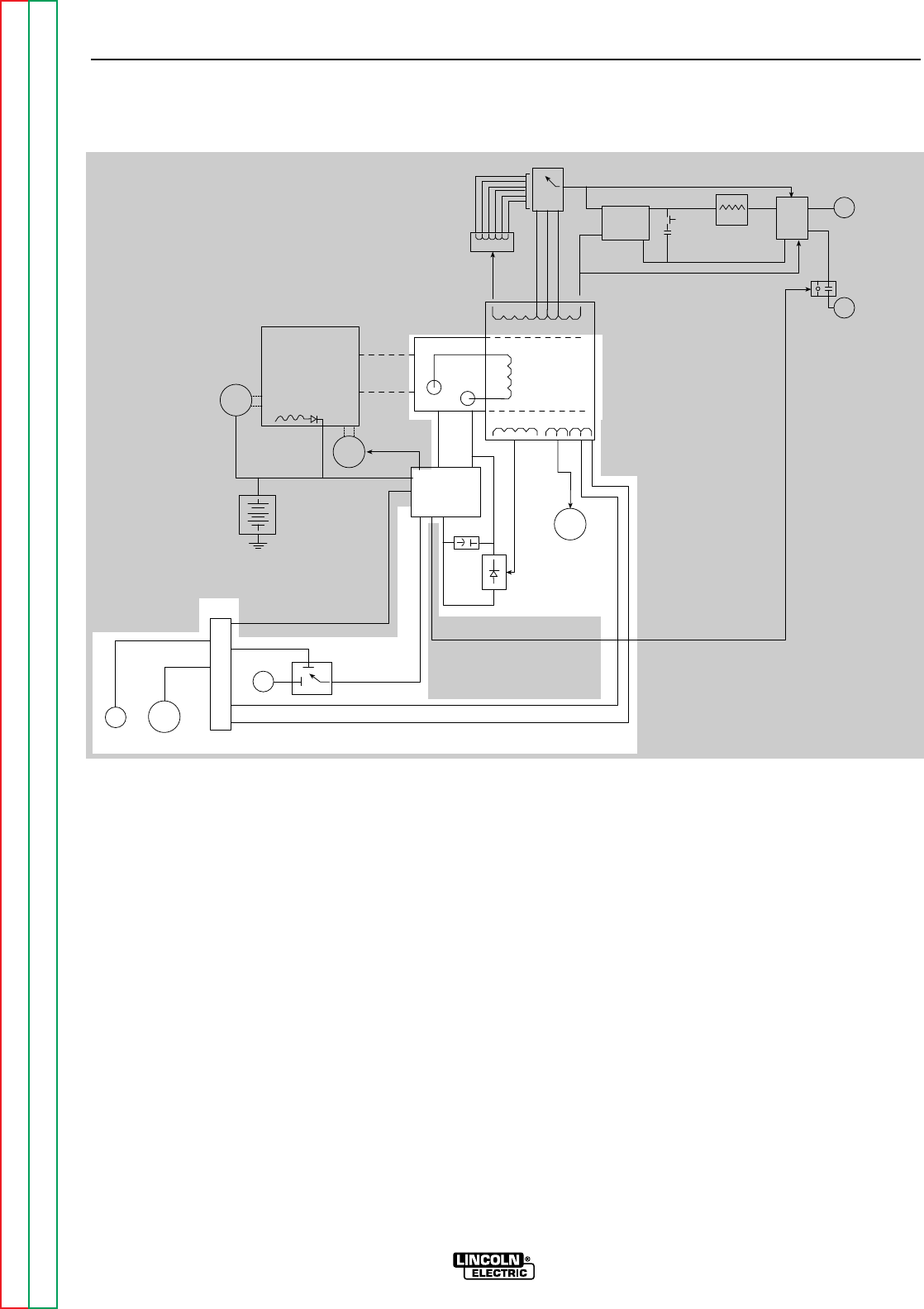
ROTOR FIELD FEEDBACK,
AUXILIARY, AND WIRE FEEDER
POWER
The AC voltage developed in the field winding is fed to
the full wave field bridge. The DC output of the bridge
is filtered by the field capacitor and controlled by the
printed circuit board according to the output control
setting. This filtered and controlled voltage is fed to
the rotor winding via the brush and slip ring configura-
tion. As the feedback voltage is increased or de-
creased, the outputs of the weld and auxiliary windings
are increased or decreased.
When full field voltage is applied to the rotor and the
engine is running at high speed (3700 RPM), a 230 AC
voltage is developed in the stator auxiliary winding.
This winding is tapped to provide 115 VAC. The two
voltages (115 VAC and 230 VAC), are connected to the
appropriate receptacles and offer 9000 watts (total) of
AC power.
The auxiliary wire feeder winding offers 115VAC and is
tapped to also provide 42VAC. The current draw from
this winding should be limited to 8 amps. These volt-
ages and remote control signals are fed through the
by-pass (filter) board to the amphenol receptacles.
THEORY OF OPERATION
E-3 E-3
RANGER 9 RANGER 9
Return to Section TOC Return to Section TOC Return to Section TOC Return to Section TOC
Return to Master TOC Return to Master TOC Return to Master TOC Return to Master TOC
NOTE: Unshaded areas of Block Logic Diagram are the subject of discussion.
FIGURE E.3 – ROTOR FIELD FEEDBACK, AUXILIARY, AND WIRE FEEDER POWER
WORK
TERMINAL
OUTPUT
CONTACTOR
ELECTRODE
TERMINAL
POLARITY
SWITCH
CHOKE
PART OF
RANGE
SWITCH
CAPACITORS
OUTPUT
RECTIFIER
BRIDGE
AC
AC
RANGE
SWITCH
REACTOR
STATOR
ROTOR
MECHANICAL
ROTATION
ROTOR
SLIP
RINGS
IDLER
SOLENOID
ENGINE
STARTER
BATTERY
FLYWHEEL
ALTERNATOR
PRINTER
CIRCUT
BOARD
FIELD
CAPACITOR
115 & 230VAC
RECEPTACLES
FIELD
BRIDGE
CONTACTOR CLOSURE
BY-PASS
BOARD CONTACTOR CLOSURE
REMOTE
SWITCH
OUTPUT
CONTROL
6 PIN
AMPHENOL 14 PIN
AMPHENOL
115VAC
42VAC
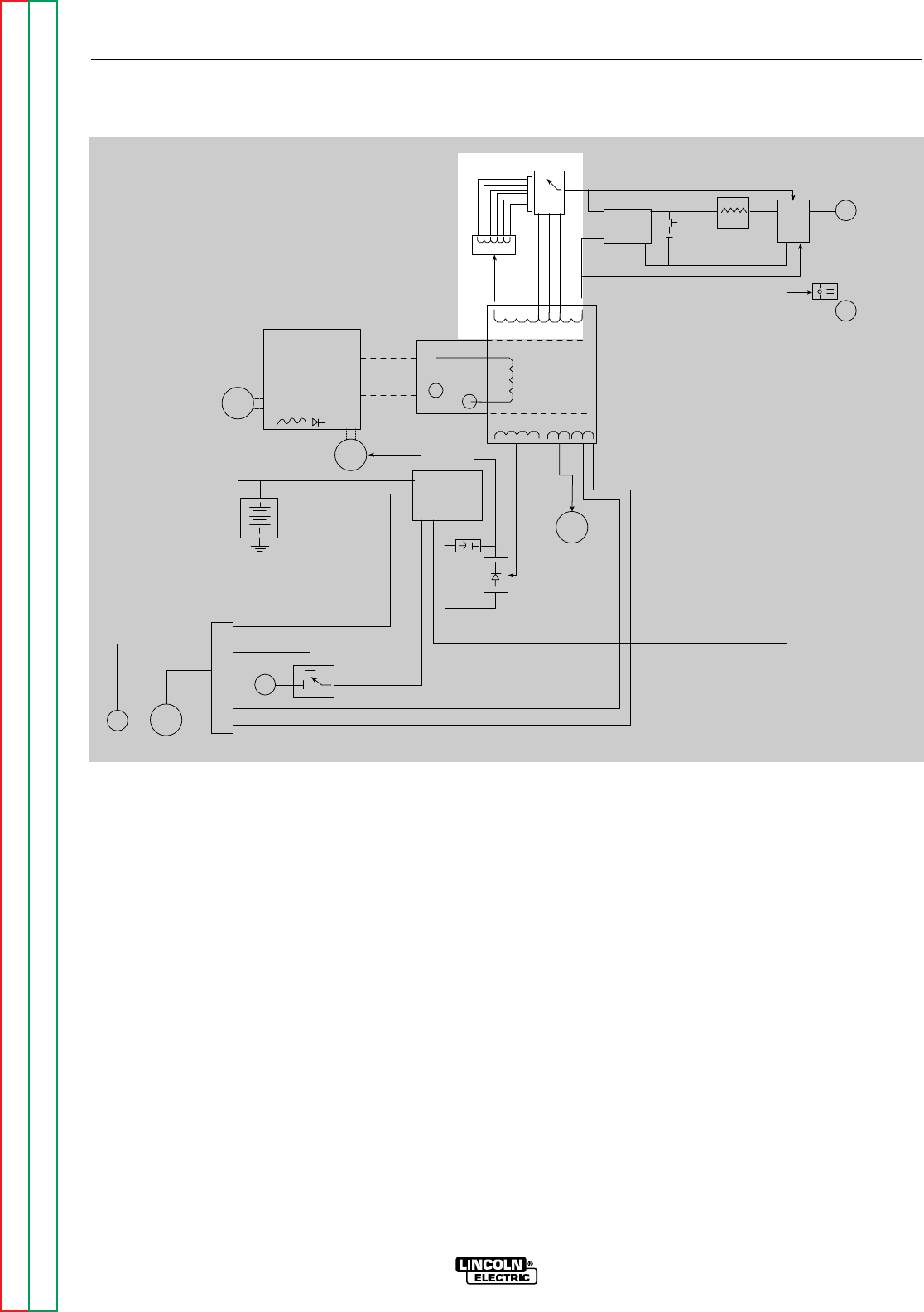
WELD WINDING, REACTOR, AND
RANGE SWITCH
The stator weld winding is connected to the reactor
and range switch. The inductance in the reactor offers
an impedance to current flow. The reactor coil is
tapped at various points. As the range switch is ro-
tated, different amounts of reactor coil are brought into
the current path. As more turns of reactor are brought
into the circuit, the more impedance there is to current
flow. Simply stated, the more reactor in the circuit, the
lower the welding current.
If a constant voltage is desired for wire feeding, then
the reactor is bypassed and the range switch is con-
nected to one of three taps on the stator weld winding
to provide a lower but “stiffer” output voltage.
THEORY OF OPERATION
E-4 E-4
RANGER 9 RANGER 9
Return to Section TOC Return to Section TOC Return to Section TOC Return to Section TOC
Return to Master TOC Return to Master TOC Return to Master TOC Return to Master TOC
WORK
TERMINAL
OUTPUT
CONTACTOR
ELECTRODE
TERMINAL
POLARITY
SWITCH
CHOKE
PART OF
RANGE
SWITCH
CAPACITORS
OUTPUT
RECTIFIER
BRIDGE
AC
AC
RANGE
SWITCH
REACTOR
STATOR
ROTOR
MECHANICAL
ROTATION
ROTOR
SLIP
RINGS
IDLER
SOLENOID
ENGINE
STARTER
BATTERY
FLYWHEEL
ALTERNATOR
PRINTER
CIRCUT
BOARD
FIELD
CAPACITOR
115 & 230VAC
RECEPTACLES
FIELD
BRIDGE
CONTACTOR CLOSURE
BY-PASS
BOARD CONTACTOR CLOSURE
REMOTE
SWITCH
OUTPUT
CONTROL
6 PIN
AMPHENOL 14 PIN
AMPHENOL
115VAC
42VAC
FIGURE E.4 – WELD WINDING, REACTOR, AND RANGE SWITCH
NOTE: Unshaded areas of Block Logic Diagram are the subject of discussion.
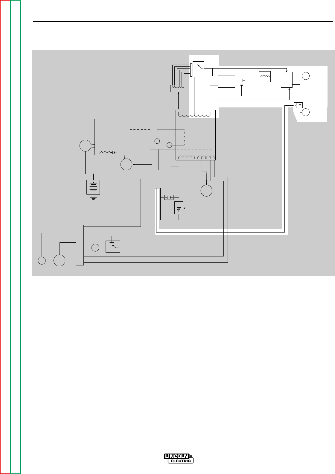
OUTPUT BRIDGE, CHOKE,
POLARITY SWITCH, AND OUTPUT
TERMINALS
The AC voltage developed in the stator weld winding
is delivered, through the reactor and range switch, to
the output bridge and polarity switch. Depending
upon the setting of the polarity switch, either AC volt-
age or DC voltage is delivered through the output con-
tactor, which is activated by the printed circuit board,
to the output terminals. If AC output is selected, then
the current path is from the stator weld winding
through the reactor, range switch, polarity switch and
output contactor to the output terminals. If a DC out-
put is called for, then the current path is through the
output bridge, where the AC voltage is rectified to a
DC voltage, and then to the choke, where the DC out-
put is filtered. The filtered DC current path is through
the polarity switch and output contactor and then on
to the output terminals.
If a CV (constant voltage) mode is desired, the reactor
is passed by. The range switch applies a lower AC
voltage to the rectifier bridge. The DC output of the
bridge is filtered and “stiffened” by the capacitors.
This lower but “stiffer” DC output is passed through
the choke, polarity switch, and contactor and then on
to the output terminals.
THEORY OF OPERATION
E-5 E-5
RANGER 9 RANGER 9
Return to Section TOC Return to Section TOC Return to Section TOC Return to Section TOC
Return to Master TOC Return to Master TOC Return to Master TOC Return to Master TOC
WORK
TERMINAL
OUTPUT
CONTACTOR
ELECTRODE
TERMINAL
POLARITY
SWITCH
CHOKE
PART OF
RANGE
SWITCH
CAPACITORS
OUTPUT
RECTIFIER
BRIDGE
AC
AC
RANGE
SWITCH
REACTOR
STATOR
ROTOR
MECHANICAL
ROTATION
ROTOR
SLIP
RINGS
IDLER
SOLENOID
ENGINE
STARTER
BATTERY
FLYWHEEL
ALTERNATOR
PRINTER
CIRCUT
BOARD
FIELD
CAPACITOR
115 & 230VAC
RECEPTACLES
FIELD
BRIDGE
CONTACTOR CLOSURE
BY-PASS
BOARD CONTACTOR CLOSURE
REMOTE
SWITCH
OUTPUT
CONTROL
6 PIN
AMPHENOL 14 PIN
AMPHENOL
115VAC
42VAC
FIGURE E.5
OUTPUT BRIDGE, CAPACITOR, CHOKE, POLARITY SWITCH, CONTACTOR AND OUTPUT TERMINALS
NOTE: Unshaded areas of Block Logic Diagram are the subject of discussion.

Section F-1 Section F-1
RANGER 9 RANGER 9
Troubleshooting & Repair Section.................................................................................Section F
How to Use Troubleshooting Guide ......................................................................................F-2
PC Board Troubleshooting Procedures.................................................................................F-3
Troubleshooting Guide.................................................................................................F4 - F-18
Test Procedures
Rotor Voltage Test.........................................................................................................F-19
Rotor Resistance Test...................................................................................................F-21
Auxiliary and Field Winding Test...................................................................................F-24
Output Rectifier Bridge Test..........................................................................................F-29
Charging Circuit Test.....................................................................................................F-31
Engine Throttle Adjustment Test...................................................................................F-33
Oscilloscope Waveforms.....................................................................................................F-37
Normal Open Circuit Voltage Waveform (115 VAC Supply)..........................................F-37
Typical DC Weld Output Waveform (CV Mode) – Machine Loaded..............................F-38
Typical DC Weld Output Waveform – Machine Loaded................................................F-39
Typical AC Weld Output Waveform – Machine Loaded................................................F-40
Abnormal Open Circuit Weld Voltage Waveform (one diode open)..............................F-41
Abnormal Open Circuit DC Weld Voltage Waveform
(High CV Mode) – Output Capacitor Bank not Functioning ...................................F-42
Normal Open Circuit Weld Voltage Waveform (High CV Mode) ...................................F-43
Normal Open Circuit DC Weld Voltage Waveform........................................................F-44
Normal Open Circuit AC Weld Voltage Waveform........................................................F-45
Replacement Procedures ....................................................................................................F-46
Brush Removal and Replacement ................................................................................F-46
Field Capacitor and Rectifier Bridge Removal and Replacement................................F-49
Printed Circuit Board Removal and Replacement........................................................F-52
Output Rectifier Bridge Removal and Replacement.....................................................F-55
Output Capacitor Removal and Replacement..............................................................F-58
Output Contactor Removal and Replacement..............................................................F-61
Engine Rotor Removal and Replacement (Kit S20788)................................................F-64
Retest After Repair ..............................................................................................................F-69
TABLE OF CONTENTS
TROUBLESHOOTING & REPAIR SECTION
Return to Master TOC Return to Master TOC Return to Master TOC Return to Master TOC

Return to Section TOC Return to Section TOC Return to Section TOC Return to Section TOC
Return to Master TOC Return to Master TOC Return to Master TOC Return to Master TOC
HOW TO USE TROUBLESHOOTING GUIDE
Service and repair should be performed by only Lincoln Electric Factory Trained Personnel.
Unauthorized repairs performed on this equipment may result in danger to the technician and machine
operator and will invalidate your factory warranty. For your safety and to avoid Electrical Shock, please
observe all safety notes and precautions detailed throughout this manual.
TROUBLESHOOTING & REPAIR
F-2 F-2
RANGER 9 RANGER 9
CAUTION
This Troubleshooting Guide is provided to help
you locate and repair possible machine malfunc-
tions. Simply follow the three-step procedure
listed below.
Step 1. LOCATE PROBLEM (SYMPTOM). Look
under the column labeled “PROBLEM (SYMP-
TOMS). This column describes possible symp-
toms that the machine may exhibit. Find the list-
ing that best describes the symptom that the
machine is exhibiting. Symptoms are grouped
into three main categories: Output Problems,
Engine Problems, and Welding Problems.
Step 2. PERFORM EXTERNAL TESTS. The
second column, labeled “POSSIBLE AREAS OF
MISADJUSTMENT(S)”, lists the obvious external
possibilities that may contribute to the machine
symptom. Perform these tests/checks in the
order listed. In general, these tests can be con-
ducted without removing the case wrap-around
cover.
Step 3. PERFORM COMPONENT TESTS. The
last column, labeled “Recommended Course of
Action” lists the most likely components that may
have failed in your machine. It also specifies the
appropriate test procedure to verify that the sub-
ject component is either good or bad. If there are
a number of possible components, check the
components in the order listed to eliminate one
possibility at a time until you locate the cause of
your problem.
All of the referenced test procedures referred to in
the Troubleshooting Guide are described in detail
at the end of this chapter. Refer to the
Troubleshooting and Repair Table of Contents to
locate each specific Test Procedure. All of the
referred to test points, components, terminal
strips, etc., can be found on the referenced elec-
trical wiring diagrams and schematics. Refer to
the Electrical Diagrams Section Table of Contents
to locate the appropriate diagram.
WARNING
If for any reason you do not understand the test procedures or are unable to perform the test/repairs
safely, contact the Lincoln Electric Service Department for electrical troubleshooting assistance before
you proceed. Call 216-383-2531 or 1-800-833-9353.
ELECTRIC SHOCK can kill.
Have an electrician install and service
this equipment. Turn the machine OFF
before working on equipment. Do not
touch electrically hot parts.
Sometimes machine failures appear to be due to PC
board failures. These problems can sometimes be
traced to poor electrical connections. To avoid prob-
lems when troubleshooting and replacing PC boards,
please use the following procedure:
1. Determine to the best of your technical ability that
the PC board is the most likely component caus-
ing the failure symptom.
2. Check for loose connections at the PC board to
assure that the PC board is properly connected.
3. If the problem persists, replace the suspect PC
board using standard practices to avoid static
electrical damage and electrical shock. Read the
warning inside the static resistant bag and perform
the following procedures:
PC Board can be damaged by
static electricity.
• Remove your body’s static charge
before opening the static-shield-
ing bag. Wear an anti-static wrist
strap. For safety, use a 1 Meg
ohm resistive cord connected to a
grounded part of the equipment
frame.
• If you don’t have a wrist strap,
touch an unpainted, grounded,
part of the equipment frame.
Keep touching the frame to pre-
vent static build-up. Be sure not
to touch any electrically live parts
at the same time.
• Tools which come in contact with the PC Board must
be either conductive, anti-static or static-dissipative.
• Remove the PC Board from the static-shielding bag
and place it directly into the equipment. Don’t set
the PC Board on or near paper, plastic or cloth which
could have a static charge. If the PC Board can’t be
installed immediately, put it back in the static-
shielding bag.
• If the PC Board uses protective shorting jumpers,
don’t remove them until installation is complete.
• If you return a PC Board to The Lincoln Electric
Company for credit, it must be in the static-shielding
bag. This will prevent further damage and allow
proper failure analysis.
4. Test the machine to determine if the failure symp-
tom has been corrected by the replacement PC
board.
NOTE: Allow the machine to heat up so that all elec-
trical components can reach their operating
temperature.
5. Remove the replacement PC board and substitute
it with the original PC board to recreate the original
problem.
a. If the original problem does not reappear
by substituting the original board, then the
PC board was not the problem. Continue
to look for bad connections in the control
wiring harness, junction blocks, and termi-
nal strips.
b. If the original problem is recreated by the
substitution of the original board, then the
PC board was the problem. Reinstall the
replacement PC board and test the
machine.
6. Always indicate that this procedure was followed
when warranty reports are to be submitted.
NOTE: Following this procedure and writing on the
warranty report, “INSTALLED AND SWITCHED
PC BOARDS TO VERIFY PROBLEM,” will help
avoid denial of legitimate PC board warranty
claims.
TROUBLESHOOTING & REPAIR
F-3 F-3
RANGER 9 RANGER 9
Return to Section TOC Return to Section TOC Return to Section TOC Return to Section TOC
Return to Master TOC Return to Master TOC Return to Master TOC Return to Master TOC
PC BOARD TROUBLESHOOTING PROCEDURES
WARNING
ATTENTION
Static-Sensitive
Devices
Handle only at
Static-Safe
Workstations
Reusable
Container
Do Not Destroy

Return to Section TOC Return to Section TOC Return to Section TOC Return to Section TOC
Return to Master TOC Return to Master TOC Return to Master TOC Return to Master TOC
TROUBLESHOOTING & REPAIR
F-4 F-4
RANGER 9 RANGER 9
Observe Safety Guidelines TROUBLESHOOTING GUIDE
detailed in the beginning of this manual.
CAUTION
If for any reason you do not understand the test procedures or are unable to perform the test/repairs safely, con-
tact the Lincoln Electric Service Department for electrical troubleshooting assistance before you proceed. Call
216-383-2531 or 1-800-833-9353.
PROBLEMS
(SYMPTOMS) POSSIBLE AREAS OF
MISADJUSTMENT(S) RECOMMENDED
COURSE OF ACTION
OUTPUT PROBLEMS
Major physical or electrical dam-
age is evident. 1. Contact your local Lincoln
Authorized Field Service
Facility.
1. Contact The Lincoln Electric
Service Dept. (216) 383-2531 or
1-800-833-9353 (WELD).
No weld output and no auxiliary
power. Engine operates normally. 1. Make sure the REMOTE switch
(S4) is in the proper position –
“MACHINE CONTROL” if a
remote control unit is NOT con-
nected to the machine.
2. Check the brushes for wear and
proper contact to the rotor slip
rings.
1. Perform the Rotor Voltage
Test.
2. If the Rotor Voltage Test is nor-
mal, then perform the Rotor
Resistance Test.
3. If the Rotor Voltage Test is NOT
normal, perform the Auxiliary
and Field winding Voltage Test.
Then check the field diode
bridge (D2), the field capacitor
(C1), and the Output Control
(R3). Replace if necessary. If
the field bridge, field capacitor
and Output Control are good,
then the printed circuit board
may be faulty. Replace.

Return to Section TOC Return to Section TOC Return to Section TOC Return to Section TOC
Return to Master TOC Return to Master TOC Return to Master TOC Return to Master TOC
TROUBLESHOOTING & REPAIR
F-5 F-5
RANGER 9 RANGER 9
TROUBLESHOOTING GUIDE Observe Safety Guidelines
detailed in the beginning of this manual.
CAUTION
If for any reason you do not understand the test procedures or are unable to perform the test/repairs safely, con-
tact the Lincoln Electric Service Department for electrical troubleshooting assistance before you proceed. Call
216-383-2531 or 1-800-833-9353.
PROBLEMS
(SYMPTOMS) POSSIBLE AREAS OF
MISADJUSTMENT(S) RECOMMENDED
COURSE OF ACTION
OUTPUT PROBLEMS
No weld output, the auxiliary
power (230-115VAC) is operating
normally. Engine operates normal-
ly.
1. With the WELDING TERMINAL
switch in the “ALWAYS ON”
position, check the open circuit
voltage (OCV) at the welder out-
put terminals. Normal maxi-
mum is 73 to 80VAC. Normal
DC maximum is 65 to 75VDC.
If the OCV is OK, then proceed
to Step #2. If the OCV is NOT
present at the welder output
terminals, contact your local
Lincoln Authorized Field
Service Facility.
2. Check the welding cables,
clamps, and electrode holder
for loose or broken connec-
tions.
1. Make sure the output contactor
is being activated. Also make
sure there is continuity (zero
ohms) through the contactor
contacts.
2. Disconnect lead W1 from the
output bridge (D1) and check
for the presence of 80VAC from
lead W1 to lead W2 on the main
stator. See Wiring Diagram. If
the AC voltage is NOT present,
the winding in the stator may be
faulty. Check the winding for
continuity, and test to be sure it
is NOT grounded to the stator
iron. Replace if necessary. If
the correct AC voltage is pre-
sent, proceed to step #3.
3. Check the reactor, Range
Switch (S2), and associated
wiring for loose or faulty con-
nections. Check the reactor
winding for continuity and test
to be sure it is NOT grounded to
the reactor iron.
4. Check the choke (L1), Polarity
Switch (S1), and associated
wires for loose or faulty connec-
tions. Check the choke winding
for continuity and test to be
sure it is NOT grounded to the
choke iron.
5. Check the weld output termi-
nals and associated wires for
loose or faulty connections.
6. Perform the Output Rectifier
Bridge Test.

Return to Section TOC Return to Section TOC Return to Section TOC Return to Section TOC
Return to Master TOC Return to Master TOC Return to Master TOC Return to Master TOC
TROUBLESHOOTING & REPAIR
F-6 F-6
RANGER 9 RANGER 9
Observe Safety Guidelines TROUBLESHOOTING GUIDE
detailed in the beginning of this manual.
CAUTION
If for any reason you do not understand the test procedures or are unable to perform the test/repairs safely, con-
tact the Lincoln Electric Service Department for electrical troubleshooting assistance before you proceed. Call
216-383-2531 or 1-800-833-9353.
PROBLEMS
(SYMPTOMS) POSSIBLE AREAS OF
MISADJUSTMENT(S) RECOMMENDED
COURSE OF ACTION
OUTPUT PROBLEMS
No auxiliary power at receptacles –
welding output is normal – engine
runs normally.
1. If the machine is equipped with
circuit breakers, check circuit
breakers, CB2 through CB7.
Reset if tripped.
2. Make sure the Output Control
(R3) is set at the maximum
position.
3. Check for a loose or faulty
plug(s) at the power recepta-
cle(s).
1. Check the auxiliary power
receptacles and associated
wires for loose or faulty con-
nections.
2. Perform the Auxiliary and
Field Winding Voltage Test.
3. If the machine is equipped with
circuit breakers, check for
faulty breakers and loose or
faulty connections on associat-
ed wiring.

Return to Section TOC Return to Section TOC Return to Section TOC Return to Section TOC
Return to Master TOC Return to Master TOC Return to Master TOC Return to Master TOC
TROUBLESHOOTING & REPAIR
F-7 F-7
RANGER 9 RANGER 9
TROUBLESHOOTING GUIDE Observe Safety Guidelines
detailed in the beginning of this manual.
CAUTION
If for any reason you do not understand the test procedures or are unable to perform the test/repairs safely, con-
tact the Lincoln Electric Service Department for electrical troubleshooting assistance before you proceed. Call
216-383-2531 or 1-800-833-9353.
PROBLEMS
(SYMPTOMS) POSSIBLE AREAS OF
MISADJUSTMENT(S) RECOMMENDED
COURSE OF ACTION
OUTPUT PROBLEMS
Machine has low welding output
and low auxiliary output. 1. Make sure the REMOTE switch
is in the proper position –
“MACHINE CONTROL” if a
remote control unit is NOT con-
nected to the machine.
2. The brushes may be worn.
Contact your local Lincoln
Authorized Service Facility.
3. The Engine RPM may be low.
1. If the engine HIGH IDLE RPM is
low, then perform the Throttle
Adjustment Test.
2. Perform the Rotor Voltage
Test.
3. If the rotor voltage is low, the
field capacitor (C1) or the field
bridge (D2) may be faulty. Test
and replace if necessary.
4. Check the Output Control
potentiometer. Normal resis-
tance is 10,000 ohms. Also
check associated wiring for
loose or faulty connections.
5. The rotor may be faulty.
Perform the Rotor Resistance
Test.
6. The printed circuit board may
be faulty. Replace.
7. If the engine HIGH IDLE RPM
IS OK, then the engine may
have lost horsepower and be in
need of major repair.

Return to Section TOC Return to Section TOC Return to Section TOC Return to Section TOC
Return to Master TOC Return to Master TOC Return to Master TOC Return to Master TOC
TROUBLESHOOTING & REPAIR
F-8 F-8
RANGER 9 RANGER 9
Observe Safety Guidelines TROUBLESHOOTING GUIDE
detailed in the beginning of this manual.
CAUTION
If for any reason you do not understand the test procedures or are unable to perform the test/repairs safely, con-
tact the Lincoln Electric Service Department for electrical troubleshooting assistance before you proceed. Call
216-383-2531 or 1-800-833-9353.
PROBLEMS
(SYMPTOMS) POSSIBLE AREAS OF
MISADJUSTMENT(S) RECOMMENDED
COURSE OF ACTION
OUTPUT PROBLEMS
No DC welding output. AC welding
output and auxiliary power are nor-
mal.
1. Make sure the Polarity switch
(S1) is in the proper position
and is “seated” correctly.
2. Make sure the electrode and
polarity are correct for the
process being used.
1. Perform the Output Rectifier
Bridge Test.
2. Check the choke (L1), the
Polarity switch (S1), and associ-
ated wires for loose or faulty
connections. Check the choke
winding for continuity and test
to be sure it is NOT grounded to
the choke iron.
No AC welding output. DC weld-
ing output and auxiliary power are
normal.
1. Make sure the Polarity switch
(S1) is in the proper position
and is “seated” correctly.
2. Make sure the electrode is cor-
rect for the process being used.
3. Make sure the welding cables
are not coiled or too long.
1. Check the operation of the
Polarity switch (S1). Also check
the associated wires for loose
or faulty connections. See
Wiring Diagram.
2. Check for continuity from lead
“S2” to lead “E” located in the
main stator. See Wiring Dia-
gram.

Return to Section TOC Return to Section TOC Return to Section TOC Return to Section TOC
Return to Master TOC Return to Master TOC Return to Master TOC Return to Master TOC
TROUBLESHOOTING & REPAIR
F-9 F-9
RANGER 9 RANGER 9
TROUBLESHOOTING GUIDE Observe Safety Guidelines
detailed in the beginning of this manual.
CAUTION
If for any reason you do not understand the test procedures or are unable to perform the test/repairs safely, con-
tact the Lincoln Electric Service Department for electrical troubleshooting assistance before you proceed. Call
216-383-2531 or 1-800-833-9353.
PROBLEMS
(SYMPTOMS) POSSIBLE AREAS OF
MISADJUSTMENT(S) RECOMMENDED
COURSE OF ACTION
OUTPUT PROBLEMS
No constant voltage (CV) welding
output. Constant current (CC) and
the auxiliary power are operating
normally.
1. Make sure the Range switch
(S2) is in the proper position
(CV) and “seated” correctly.
2. Make sure the wire feeder and
welding cables are connected
correctly.
1. Check the operation of the
Range switch (S2) and check
the associated wires for loose
or faulty connections. See
Wiring Diagram.
2. Check for continuity from leads
C1, C2, and C3 to lead W1
located in the main stator. See
Wiring Diagram.
The constant voltage (CV) welding
output is low or unstable.
Constant current (CC) and the aux-
iliary power are operating normally.
1. Make sure the Range switch
(S2) is in the proper position
(CV) and “seated” correctly.
2. Make sure the wire feeder and
welding cables are connected
correctly.
1. Check the operation of the
Range switch (S2) and check
the associated wires for loose
or faulty connections. See
Wiring Diagram.
2. The capacitor bank (C2, C3, C4,
C5) may be faulty. Check or
replace.

Return to Section TOC Return to Section TOC Return to Section TOC Return to Section TOC
Return to Master TOC Return to Master TOC Return to Master TOC Return to Master TOC
TROUBLESHOOTING & REPAIR
F-10 F-10
RANGER 9 RANGER 9
Observe Safety Guidelines TROUBLESHOOTING GUIDE
detailed in the beginning of this manual.
CAUTION
If for any reason you do not understand the test procedures or are unable to perform the test/repairs safely, con-
tact the Lincoln Electric Service Department for electrical troubleshooting assistance before you proceed. Call
216-383-2531 or 1-800-833-9353.
PROBLEMS
(SYMPTOMS) POSSIBLE AREAS OF
MISADJUSTMENT(S) RECOMMENDED
COURSE OF ACTION
ENGINE PROBLEMS
Engine will not idle down to low
speed. Machine has normal weld
output and auxiliary power.
1. Make sure the Idler switch (S5)
is in the “Auto” position.
2. Make sure there is NOT an
external load on the weld termi-
nals nor the auxiliary power
receptacles.
1. With the Idler switch (S5) in the
“AUTO” position and the engine
running, check for the presence
of 12VDC at leads #224D to
#214, located at the Idler sole-
noid. If 12VDC is present and
the idler solenoid is not activat-
ing, then the solenoid may be
faulty or there is a mechanical
restriction preventing it from
functioning.
2. If there is NOT 12VDC at leads
#224D to #214, then test for
12VDC from lead #224D to
ground (lead #5). See Wiring
Diagram. If 12VDC is present,
then check lead #214 for conti-
nuity (zero ohms) from the idler
solenoid to the printed circuit
board plug 8J1. Also check the
idler switch (S5) and the associ-
ated leads. See Wiring
Diagram. If the above are OK,
then the printed circuit board
may be faulty. Replace.
3. If there is NOT 12VDC from lead
#224D to ground (lead #5), then
check the wiring to the engine
terminal block connection. See
Wiring Diagram.

Return to Section TOC Return to Section TOC Return to Section TOC Return to Section TOC
Return to Master TOC Return to Master TOC Return to Master TOC Return to Master TOC
TROUBLESHOOTING & REPAIR
F-11 F-11
RANGER 9 RANGER 9
TROUBLESHOOTING GUIDE Observe Safety Guidelines
detailed in the beginning of this manual.
CAUTION
If for any reason you do not understand the test procedures or are unable to perform the test/repairs safely, con-
tact the Lincoln Electric Service Department for electrical troubleshooting assistance before you proceed. Call
216-383-2531 or 1-800-833-9353.
PROBLEMS
(SYMPTOMS) POSSIBLE AREAS OF
MISADJUSTMENT(S) RECOMMENDED
COURSE OF ACTION
ENGINE PROBLEMS
Engine will not go to high idle when
attempting to weld. Welding out-
put is normal when Idler switch is
in “HIGH” position. Automatic idle
function works properly when the
auxiliary power is loaded.
1. Make sure the welding cables
and connections are tight.
2. If attempting to “scratch” start,
the WELDING TERMINALS
switch (S6) must be in the
“ALWAYS ON” position.
1. Check for broken or faulty con-
nections in the sensing leads
(#254 and #254A). Make sure
their connections are tight at
the work output terminal and
also at the Polarity switch. See
Wiring Diagram.
2. Make sure the leads are looped
three times through the current
sensor on the printed circuit
board.
3. If using a wire feeder with a
control cable, check the #2 and
#4 circuit in the cable and in the
machine. See Wiring Diagram.
Engine will not go to high idle when
attempting to weld or when the
auxiliary power is loaded. Welding
output and auxiliary power output
is normal when Idler switch is in the
“HIGH” position.
1. Make sure the welding cables
and connections are tight.
2. Automatic idler may not func-
tion if the auxiliary power is
loaded to less than 150 watts.
1. Check for broken or faulty con-
nections in the sensing leads
(#254 and #254A). Make sure
their connections are tight at
the work output terminal and
also at the Polarity switch. See
Wiring Diagram.
2. Check lead #3 making sure it is
looped through the current sen-
sor on the printed circuit board.
3. The printed circuit board may
be faulty. Replace.

Return to Section TOC Return to Section TOC Return to Section TOC Return to Section TOC
Return to Master TOC Return to Master TOC Return to Master TOC Return to Master TOC
F-12 F-12
RANGER 9 RANGER 9
TROUBLESHOOTING & REPAIR
TROUBLESHOOTING GUIDE Observe Safety Guidelines
detailed in the beginning of this manual.
CAUTION
If for any reason you do not understand the test procedures or are unable to perform the test/repairs safely, con-
tact the Lincoln Electric Service Department for electrical troubleshooting assistance before you proceed. Call
216-383-2531 or 1-800-833-9353.
PROBLEMS
(SYMPTOMS) POSSIBLE AREAS OF
MISADJUSTMENT(S) RECOMMENDED
COURSE OF ACTION
ENGINE PROBLEMS
Engine will not crank or cranks
very slowly. 1. Check for loose or faulty bat-
tery cable connections.
2. The battery may be faulty.
1. If the battery is replaced or
tests good, then the charging
circuit may be faulty. Perform
the Charging Circuit Test.
2. The starter motor or starter
solenoid may be faulty.
3. The engine may be hard to
crank due to a mechanical fail-
ure in the engine.
The engine shuts off or will not
start. 1. The engine may be low or out of
fuel.
2. The oil level may be low. Check
and fill to proper level.
3. The fuel filter may be clogged.
1. The oil pressure switch may be
faulty. Replace if necessary.
See Wiring Diagram.
The engine does not develop full
power. 1. The fuel filter may be clogged.
Replace if necessary.
2. The air filter may be clogged.
Replace if necessary.
3. The spark plug may be faulty.
Replace if necessary.
1. Due to wear, the engine may be
in need of major repair.

Return to Section TOC Return to Section TOC Return to Section TOC Return to Section TOC
Return to Master TOC Return to Master TOC Return to Master TOC Return to Master TOC
TROUBLESHOOTING & REPAIR
F-13 F-13
RANGER 9 RANGER 9
Observe Safety Guidelines TROUBLESHOOTING GUIDE
detailed in the beginning of this manual.
PROBLEMS
(SYMPTOMS) POSSIBLE AREAS OF
MISADJUSTMENT(S) RECOMMENDED
COURSE OF ACTION
WELDING PROBLEMS
The welding arc is “ cold.” The
engine runs normally (3700 RPM
no load). The auxiliary power is
functioning normally.
1. Check for loose or faulty con-
nections at the weld output ter-
minals and welding cable con-
nections.
2. The welding cable may be too
long or coiled, causing an
excessive voltage drop.
1. Check for the correct open cir-
cuit voltage (OCV) at the weld-
ing output terminals, 80VAC
Max. 75VDC Max. If the cor-
rect voltage is present at the
output terminals, then check for
loose connections on the heavy
current carrying leads inside the
RANGER 9. See Wiring
Diagram.
2. If the OCV is low at the welder
output terminals, then perform
the Engine Throttle Adjust-
ment Test.
3. Perform the Output Bridge
Test.
4. Check for shorted or grounded
windings in the reactor and also
in the main stator. See Wiring
Diagram.
CAUTION
If for any reason you do not understand the test procedures or are unable to perform the test/repairs safely, con-
tact the Lincoln Electric Service Department for electrical troubleshooting assistance before you proceed. Call
216-383-2531 or 1-800-833-9353.

Return to Section TOC Return to Section TOC Return to Section TOC Return to Section TOC
Return to Master TOC Return to Master TOC Return to Master TOC Return to Master TOC
TROUBLESHOOTING & REPAIR
F-14 F-14
RANGER 9 RANGER 9
TROUBLESHOOTING GUIDE Observe Safety Guidelines
detailed in the beginning of this manual.
PROBLEMS
(SYMPTOMS) POSSIBLE AREAS OF
MISADJUSTMENT(S) RECOMMENDED
COURSE OF ACTION
FUNCTION PROBLEMS
Output control on welder not func-
tioning. 1. Make sure the REMOTE switch
(S4) is in the MACHINE CON-
TROL position.
2. The Output Control (R3) may be
defective.
1. Check the Output Control (R3).
Normal resistance is 10,000
ohms. Replace if defective.
2. Check the REMOTE switch (S4)
and associated wiring. See
Wiring Diagram (Leads 75, 76,
and 77).
3. The Printed Circuit board may
be faulty. Replace.
Remote output control not func-
tioning. 1. Make sure the REMOTE switch
(S4) is in the REMOTE position.
2. The remote control unit may be
defective. Repair or replace.
1. Check the REMOTE switch (S4)
and associated wiring. See
Wiring Diagram (Leads #75, 76
and 77).
2. The bypass PC board may be
faulty. Check or replace.
CAUTION
If for any reason you do not understand the test procedures or are unable to perform the test/repairs safely, con-
tact the Lincoln Electric Service Department for electrical troubleshooting assistance before you proceed. Call
216-383-2531 or 1-800-833-9353.

Return to Section TOC Return to Section TOC Return to Section TOC Return to Section TOC
Return to Master TOC Return to Master TOC Return to Master TOC Return to Master TOC
TROUBLESHOOTING & REPAIR
F-15 F-15
RANGER 9 RANGER 9
TROUBLESHOOTING GUIDE Observe Safety Guidelines
detailed in the beginning of this manual.
PROBLEMS
(SYMPTOMS) POSSIBLE AREAS OF
MISADJUSTMENT(S) RECOMMENDED
COURSE OF ACTION
FUNCTION PROBLEMS
The wire feeder does not work
when connected to the welder
amphenol.
1. Check circuit breaker CB1.
Reset is tripped.
2. The wire feeder control cable
may be faulty. Check or
replace.
3. The wire feeder may be faulty.
Check or replace.
1. Check for the presence of
115VAC at leads #31A and 32.
See Wiring Diagram.
2. Check for the presence of
42VAC at leads 31B to 42. See
Wiring Diagram.
3. If any of the above voltages are
missing or low, then check the
circuit breaker CB1 for proper
operation.
4. The bypass PC board may be
defective. Check or replace.
5. Perform the Auxiliary and Field
Winding Test.
CAUTION
If for any reason you do not understand the test procedures or are unable to perform the test/repairs safely, con-
tact the Lincoln Electric Service Department for electrical troubleshooting assistance before you proceed. Call
216-383-2531 or 1-800-833-9353.

Return to Section TOC Return to Section TOC Return to Section TOC Return to Section TOC
Return to Master TOC Return to Master TOC Return to Master TOC Return to Master TOC
TROUBLESHOOTING & REPAIR
F-16 F-16
RANGER 9 RANGER 9
TROUBLESHOOTING GUIDE Observe Safety Guidelines
detailed in the beginning of this manual.
PROBLEMS
(SYMPTOMS) POSSIBLE AREAS OF
MISADJUSTMENT(S) RECOMMENDED
COURSE OF ACTION
FUNCTION PROBLEMS
The contactor does not pull in
when scratch starting when the
engine goes to high idle.
1. Make sure the WELDING TER-
MINALS switch (S6) is in the
“ALWAYS ON” position.
1. Check the WELDING TERMI-
NAL switch (S6) and associated
wiring.
2. Check for the presence of
12VDC from lead #224 (+) to
lead #232 (-) at the output con-
tactor. If the correct voltage IS
present and the contactor does
not activate, then the contactor
may be defective. Replace.
3. If the correct voltage is NOT
present in step #2, check from
lead #224 to ground (lead #5)
for the presence of 12VDC. If
the 12VDC is present, then
check lead #232A to the Idler
printed circuit board.
4. The printed circuit board may
be faulty. Replace.
5. If 12VDC is NOT present from
lead #224 to ground (lead #5),
then check the #224 lead for an
open circuit. See Wiring
Diagram.
CAUTION
If for any reason you do not understand the test procedures or are unable to perform the test/repairs safely, con-
tact the Lincoln Electric Service Department for electrical troubleshooting assistance before you proceed. Call
216-383-2531 or 1-800-833-9353.

Return to Section TOC Return to Section TOC Return to Section TOC Return to Section TOC
Return to Master TOC Return to Master TOC Return to Master TOC Return to Master TOC
TROUBLESHOOTING & REPAIR
F-17 F-17
RANGER 9 RANGER 9
TROUBLESHOOTING GUIDE Observe Safety Guidelines
detailed in the beginning of this manual.
PROBLEMS
(SYMPTOMS) POSSIBLE AREAS OF
MISADJUSTMENT(S) RECOMMENDED
COURSE OF ACTION
FUNCTION PROBLEMS
The output contactor does not pull
in when using a wire feeder with a
control cable connected to the
RANGER 9 amphenol.
1. Make sure the WELDING TER-
MINALS switch (S6) is in the
“REMOTELY CONTROLLED”
position.
2. Install a jumper wire from pins
“D” to “C” on the 14 pin amphe-
nol. If the output contactor acti-
vates, the problem is external to
the RANGER 9. The wire feed-
er or the control cable may be
faulty.
1. With the jumper installed in pins
“D” and “C” in the 14 pin
amphenol, check for 12VDC
from leads #224 (+) to #232 (-)
at the output contactor. If
12VDC is present and the con-
tactor does not activate, then
the contactor may be defective.
2. If the correct voltage is NOT
present in step #2, check from
lead #224 to ground (lead #5)
for the presence of 12VDC. If
12VDC is present, then check
the continuity of the lead #232A
to the idler printed circuit board.
3. The printed circuit board may
be faulty. Replace.
4. If 12VDC is NOT present from
lead #224 to ground (lead #5),
then check the #224 lead for an
open circuit. See Wiring
Diagram.
CAUTION
If for any reason you do not understand the test procedures or are unable to perform the test/repairs safely, con-
tact the Lincoln Electric Service Department for electrical troubleshooting assistance before you proceed. Call
216-383-2531 or 1-800-833-9353.

Return to Section TOC Return to Section TOC Return to Section TOC Return to Section TOC
Return to Master TOC Return to Master TOC Return to Master TOC Return to Master TOC
TROUBLESHOOTING & REPAIR
F-18 F-18
RANGER 9 RANGER 9
TROUBLESHOOTING GUIDE Observe Safety Guidelines
detailed in the beginning of this manual.
PROBLEMS
(SYMPTOMS) POSSIBLE AREAS OF
MISADJUSTMENT(S) RECOMMENDED
COURSE OF ACTION
FUNCTION PROBLEMS
The output contactor does NOT
drop out. 1. Make sure the WELDING TER-
MINALS switch (S6) is in the
“REMOTELY CONTROLLED”
position.
2. Remove the wire feeder control
cable from the amphenol. If the
contactor “drops out,” then the
problem is external to the
RANGER 9. Check the control
cable or the wire feeder.
1. Remove lead #232 from the
output contactor. If the contac-
tor “drops out,” then make sure
that lead #232 is NOT ground-
ed. Also check the WELDING
TERMINALS switch (S6) for
proper operation. Check asso-
ciated wiring. See Wiring
Diagram. The printed circuit
board may be faulty. Replace.
2. If in step #1 the contactor does
NOT drop out, then the contac-
tor may be stuck. Repair or
replace.
CAUTION
If for any reason you do not understand the test procedures or are unable to perform the test/repairs safely, con-
tact the Lincoln Electric Service Department for electrical troubleshooting assistance before you proceed. Call
216-383-2531 or 1-800-833-9353.

Return to Section TOC Return to Section TOC Return to Section TOC Return to Section TOC
Return to Master TOC Return to Master TOC Return to Master TOC Return to Master TOC
TROUBLESHOOTING & REPAIR
F-19 F-19
RANGER 9 RANGER 9
ROTOR VOLTAGE TEST
Service and repair should be performed by only Lincoln Electric factory trained personnel.
Unauthorized repairs performed on this equipment may result in danger to the technician or
machine operator and will invalidate your factory warranty. For your safety and to avoid elec-
trical shock, please observe all safety notes and precautions detailed throughout this manual.
If for any reason you do not understand the test procedures or are unable to perform the
test/repairs safely, contact the Lincoln Electric Service Department for electrical trou-
bleshooting assistance before you proceed. Call 216-383-2531 or 1-800-833-9353 (WELD).
TEST DESCRIPTION
This test will determine if the correct DC voltage is being applied to the rotor at maximum
engine speed (3700 RPM). This information will aid the technician in determining if the gen-
erator field is operating properly.
MATERIALS NEEDED
Volt/Ohmmeter
5/16” Nut driver
Wiring Diagram
WARNING
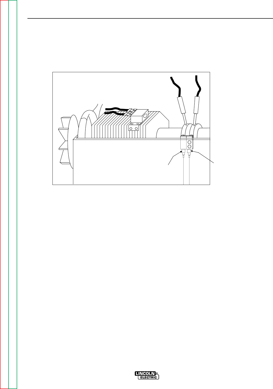
Return to Section TOC Return to Section TOC Return to Section TOC Return to Section TOC
Return to Master TOC Return to Master TOC Return to Master TOC Return to Master TOC
F-20 F-20
RANGER 9 RANGER 9
ROTOR VOLTAGE TEST (continued)
FIGURE F.1 - LOCATION OF LEAD 200A AND 219 FOR ROTOR VOLTAGE TEST
Lead #219A
Lead #200A
TROUBLESHOOTING & REPAIR
TEST PROCEDURE
1. With the 5/16” nut driver, remove the 6
sheet metal screws from the case top.
2. Remove the rubber gasket (cover seal)
from the lift bale.
3. Remove the fuel cap. The rubber gasket
for the fill tube will come off with the case
top.
4. Remove the case top, then reinstall the
fuel cap.
5. With the 5/16” nut driver, remove the 5
screws holding the right case side.
6. Remove the right case side by lifting up
and out.
7. Set the volt/ohmmeter to the DC volts
position.
8. Connect the positive meter probe to the
brush nearest the rotor lamination (lead
#200A). See Figure F.1 for location.
9. Connect the negative meter probe to the
other brush (lead #219).
10. Start the engine and run it at high idle
(3700 RPM). Set the output control to the
MAXIMUM position (position 10).
11. Check the voltage reading on the volt-
meter. It should read between 40 and 50
VDC.
12. If the voltage reading is low or not pre-
sent, the generator field is not functioning
properly. Perform the Rotor Resistance
Test. The Field Diode Bridge (D2), the
Field Capacitor (C1), and/or the Printed
Circuit Board may be faulty.
13. If the voltage reading is normal, the field
circuit is functioning properly. Install the
right case side with the 5 sheet metal
screws with the 5/16” nut driver. Remove
the fuel cap; install the case top and tight-
en the 6 sheet metal screws with the
5/16” nut driver. Install the rubber gasket
over the lift bale and install the fuel cap.
– +

Return to Section TOC Return to Section TOC Return to Section TOC Return to Section TOC
Return to Master TOC Return to Master TOC Return to Master TOC Return to Master TOC
ROTOR RESISTANCE TEST
Service and repair should be performed by only Lincoln Electric factory trained personnel.
Unauthorized repairs performed on this equipment may result in danger to the technician or
machine operator and will invalidate your factory warranty. For your safety and to avoid elec-
trical shock, please observe all safety notes and precautions detailed throughout this manual.
If for any reason you do not understand the test procedures or are unable to perform the
test/repairs safely, contact the Lincoln Electric Service Department for electrical trou-
bleshooting assistance before you proceed. Call 216-383-2531 or 1-800-833-9353 (WELD).
TEST DESCRIPTION
This test will determine if there is a shorted winding in the rotor or if the rotor is grounded.
MATERIALS NEEDED
Volt/Ohmmeter
5/16” Nut driver
Wiring Diagram
TROUBLESHOOTING & REPAIR
F-21 F-21
RANGER 9 RANGER 9
WARNING
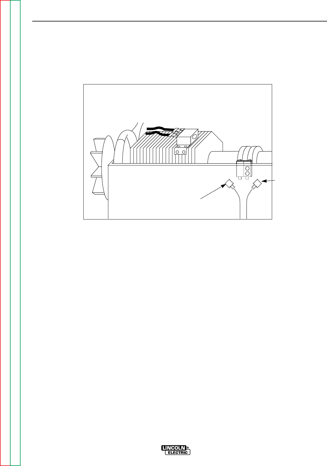
Return to Section TOC Return to Section TOC Return to Section TOC Return to Section TOC
Return to Master TOC Return to Master TOC Return to Master TOC Return to Master TOC
TROUBLESHOOTING & REPAIR
F-22 F-22
RANGER 9 RANGER 9
ROTOR RESISTANCE TEST (continued)
FIGURE F.2 – LOCATION OF ROTOR SLIP RINGS
TEST PROCEDURE
1. With the 5/16” nut driver, remove the 6
sheet metal screws from the case top.
2. Remove the rubber gasket (cover seal)
from the lift bale.
3. Remove the fuel cap. The rubber gasket
for the fill tube will come off with the case
top.
4. Remove the case top, then replace the
fuel cap.
5. With the 5/16” nut driver, remove the 5
screws holding the right case side.
6. Remove the right case side by lifting up
and out.
7. Conduct the test with the gasoline engine
OFF.
8. Remove the spark plug wires to prevent
accidental engine kickback or starting.
9. Isolate the rotor electrically by removing
the generator brush leads. Refer to
Figure F.2 as you perform the remaining
steps.
10. Remove lead #219 from the negative
brush.
11. Remove lead #200A from the positive
brush.
12. Measure the resistance across the rotor
slip rings.
A. Set the ohmmeter on the low scale
(X1).
B. Place one meter probe on one of the
rotor slip rings. Place the other probe
on the other slip ring.
C. Check the resistance across the slip
rings. It should read between 7 and 8
ohms.
Lead #219A
Lead #200A

Return to Section TOC Return to Section TOC Return to Section TOC Return to Section TOC
Return to Master TOC Return to Master TOC Return to Master TOC Return to Master TOC
TROUBLESHOOTING & REPAIR
F-23 F-23
RANGER 9 RANGER 9
13. Measure the resistance to ground.
A. Set the ohmmeter on the high scale
(X100,000).
B. Place one probe on either of the slip
rings. Place the other probe on any
good, unpainted ground. The
machine ground stud works well.
C. Check the resistance. It should read
very high, at least 0.5 megohm
(500,000 ohms).
If the test does not meet the resistance
specifications, then the rotor may be
faulty. Replace the rotor.
If the test does meet the resistance
specifications, then the rotor is okay.
14. Connect lead #200A to the positive
brush, which is the one nearest the rotor
lamination. Connect lead #219 to the
negative brush.
15. Reinstall the case side, case top, fuel
cap, lift bale gasket and spark plug
wires.

Return to Section TOC Return to Section TOC Return to Section TOC Return to Section TOC
Return to Master TOC Return to Master TOC Return to Master TOC Return to Master TOC
TROUBLESHOOTING & REPAIR
F-24 F-24
RANGER 9 RANGER 9
WARNING
AUXILIARY AND FIELD WINDING TEST
Service and repair should be performed by only Lincoln Electric factory trained personnel.
Unauthorized repairs performed on this equipment may result in danger to the technician or
machine operator and will invalidate your factory warranty. For your safety and to avoid elec-
trical shock, please observe all safety notes and precautions detailed throughout this manual.
If for any reason you do not understand the test procedures or are unable to perform the
test/repairs safely, contact the Lincoln Electric Service Department for electrical trou-
bleshooting assistance before you proceed. Call 216-383-2531 or 1-800-833-9353 (WELD).
TEST DESCRIPTION
This test will determine if the correct AC voltages are being generated from the stator
windings.
MATERIALS NEEDED
Volt/Ohmmeter
5/16” Nut driver
Wiring Diagram
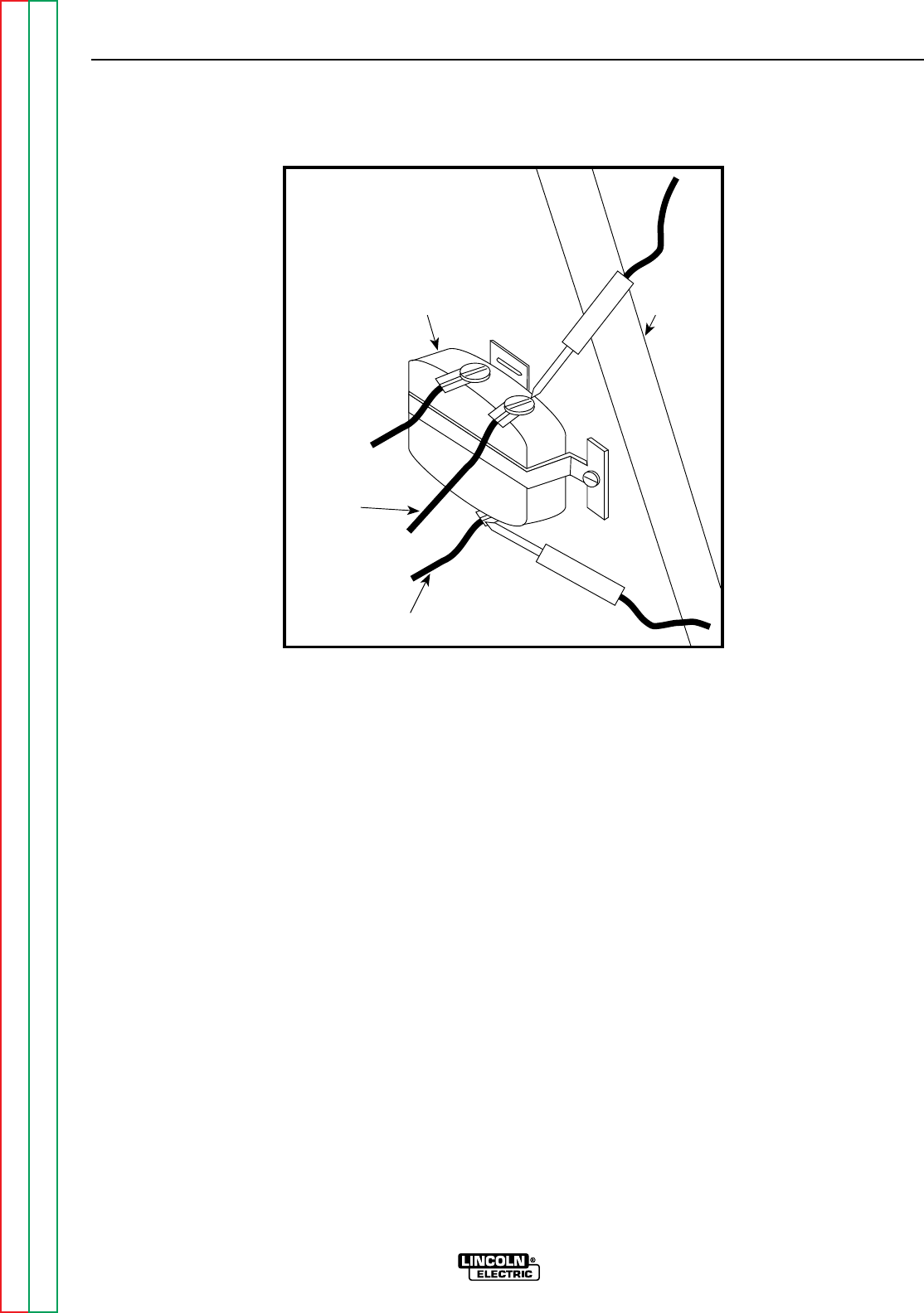
Return to Section TOC Return to Section TOC Return to Section TOC Return to Section TOC
Return to Master TOC Return to Master TOC Return to Master TOC Return to Master TOC
TROUBLESHOOTING & REPAIR
F-25 F-25
RANGER 9 RANGER 9
AUXILIARY AND FIELD WINDING TEST (continued)
FIGURE F.3 – LOCATION OF LEADS #3 AND #5
Lead #3
Lead #5
115V
Receptacle
Machine
Case
Front
TEST PROCEDURE
To test the 115 VAC winding:
1. Remove the fuel cap and lift bale rubber
gasket. With the 5/16” nut driver, remove
the case top and left side; then reinstall the
fuel cap.
2. Connect the volt/ohmmeter probes to
leads #3 and #5 where they connect to the
115 VAC receptacle. See Figure F.3.
3. Start the engine and run it at high idle (3700
RPM).
4. Set the output control to the maximum
position (position 10).
5. Check the AC voltage reading. It should be
approximately 125 VAC.
To test the 230 VAC winding:
1. Remove the fuel cap and lift bale rubber
gasket. With the 5/16” nut driver, remove
the case top and left side; then reinstall
the fuel cap.
2. Connect the volt/ohmmeter probes to
leads #6 and #3 where they connect to the
230 VAC receptacle.
NOTE: It is easier to insert the probes direct-
ly into the receptacle to perform this test.
However, the probes may not reach in far
enough to make or keep a good connection.
In this case, before you start the gasoline
engine, insert two test probes into the recep-
tacle. Hold the test probes firmly in place to
measure voltage (Step 5).
3. Start the engine and run it at high idle (3700
RPM)
4. Set the output control to the maximum
position (position 10).
5. Check the AC voltage reading. It should be
approximately 240 VAC.
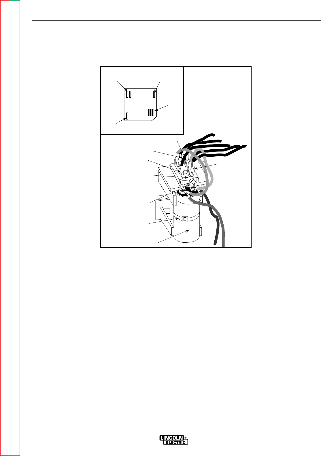
Return to Section TOC Return to Section TOC Return to Section TOC Return to Section TOC
Return to Master TOC Return to Master TOC Return to Master TOC Return to Master TOC
TROUBLESHOOTING & REPAIR
F-26 F-26
RANGER 9 RANGER 9
AUXILIARY AND FIELD WINDING TEST (continued)
Retaining
Tab
Field
Bridge
Rectifier
7
9
Capacitor
201
201A
200
200A
200B
Cable Tie
201
201A
200
200A
200B
7
9+
_AC
AC
FIGURE F.4 - LOCATION OF LEADS #7 AND #9 AT FIELD BRIDGE RECTIFIER
To test the field winding:
1. Remove the fuel cap and lift bale rubber
gasket. With the 5/16” nut driver, remove
the case top and left side; then reinstall
the fuel cap.
2. Connect the volt/ohmmeter probes to leads
#7 and #9 where they connect to the Field
Bridge Rectifier. See Figure F.4.
3. Start the engine and run it at high idle (3700
RPM).
4. Set the output control to the maximum
position (position 10).
5. Check the AC voltage reading. It should be
between 40 and 50 VAC.
If any one or more of the readings are missing
or not within specifications, then check for
loose or broken wires between the test points
and the stator windings. See the Wiring
Diagram. Make sure the windings are NOT
grounded internally to the stator iron. If the
leads are intact, then the stator may be faulty.
Replace the stator.
If the voltage readings are within specifica-
tions, then the windings are good and func-
tioning properly.
6. Reinstall the case side, case top, fuel cap,
and lift bale gasket.
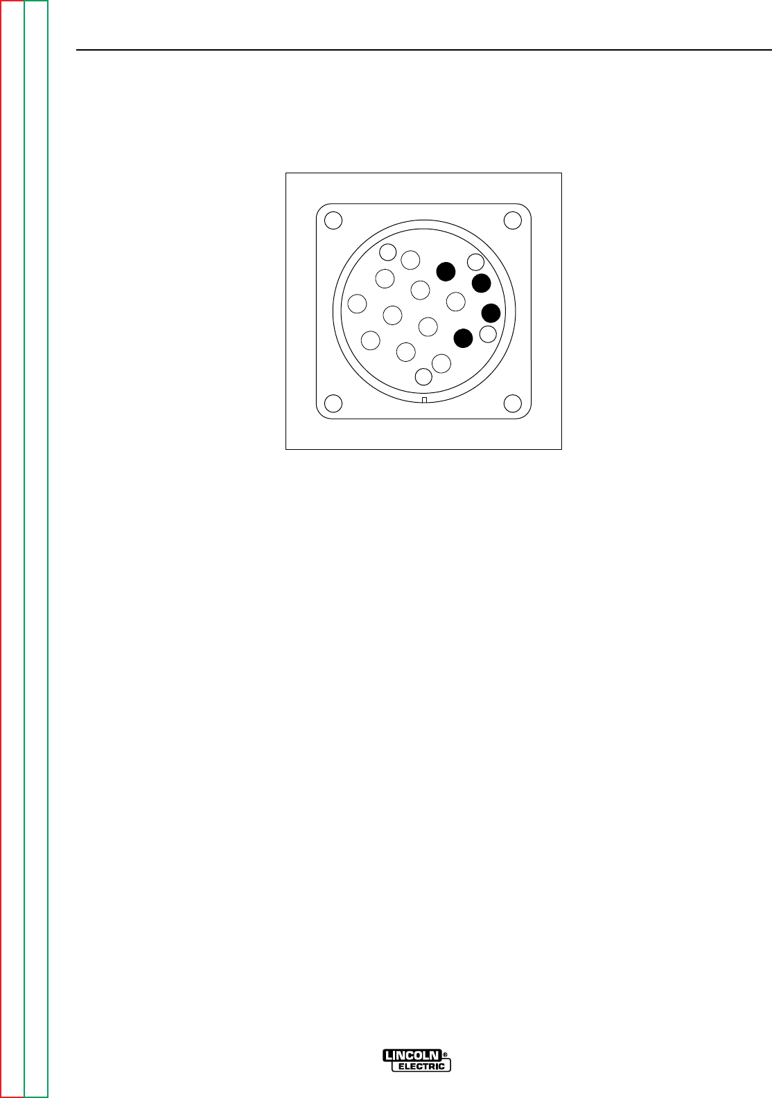
Return to Section TOC Return to Section TOC Return to Section TOC Return to Section TOC
Return to Master TOC Return to Master TOC Return to Master TOC Return to Master TOC
TROUBLESHOOTING & REPAIR
F-27 F-27
RANGER 9 RANGER 9
AUXILIARY AND FIELD WINDING TEST (continued)
Z
W
Y
X
K
B
IH
N
L
C
D
M
G
E
F
J
A
FIGURE F.4A - 14 PIN AMPHENOL PIN ASSIGNMENTS
To test the feeder winding:
1. Remove the fuel cap and lift bail rubber
gasket. With the 5/16” nut driver, remove
the case top and left side; then reinstall the
fuel cap.
2. Connect the volt/ohmmeter probes to leads
#31 and #32 where they connect to the cir-
cuit breaker CB1 and the 14 pin amphenol.
See the Wiring Diagram.
NOTE: It is possible to check this voltage
reading at the amphenol by inserting
the test probes at pin A (for lead #32)
and J (for lead #31A). See Figure 4A.
However, if you use this method and
get no voltage reading, it could mean
there is a break or loose connection in
the leads between the circuit breaker
and the amphenol. Check the reading
again with one probe at the circuit
breaker connection for lead #31 and
the other probe at amphenol pin A.
3. Start the engine and run it at high idle (3700
RPM).
4. Set the output control to the maximum
(position 10).
5. Check the AC voltage reading. It should be
between 115 and 126 VAC.
6. Connect the volt/ohmmeter probes to leads
#31 and #42 where they connect to the cir-
buit breaker CB1 and the 14 pin amphenol.
See the Wiring Diagram.
NOTE: It is possible to check this voltage
reading at the amphenol by inserting
the test probes at pin K (for lead #42)
and I (for lead #31B). See Figure 4A.
However, if you use this method and
get no voltage reading, it could mean
there is a break or loose connection in
the leads between the circuit breaker
and the amphenol. Check the reading
again with one probe at the circuit
breaker connection for lead #31 and
the other probe at amphenol pin K.
7. Set the output control to the maximum
position (position 10).
8. Check the AC voltage reading. It should be
between 43 and 50 VAC.

Return to Section TOC Return to Section TOC Return to Section TOC Return to Section TOC
Return to Master TOC Return to Master TOC Return to Master TOC Return to Master TOC
TROUBLESHOOTING & REPAIR
F-28 F-28
RANGER 9 RANGER 9
AUXILIARY AND FIELD WINDING TEST (continued)
If the voltage readings are within specifica-
tions, then the windings are good and func-
tioning correctly.
If any one or more of the readings are missing
or not within specifications, then check for
loose or broken wires between the test points
and the stator windings. See the Wiring
Diagram. Make sure that the windings are NOT
grounded internally to the stator iron. If the
leads are intact, then the stator may be faulty.
Replace the stator.
9. Reinstall the left case side, case top, fuel
cap, and lift bail gasket.

Return to Section TOC Return to Section TOC Return to Section TOC Return to Section TOC
Return to Master TOC Return to Master TOC Return to Master TOC Return to Master TOC
TROUBLESHOOTING & REPAIR
F-29 F-29
RANGER 9 RANGER 9
WARNING
OUTPUT RECTIFIER BRIDGE TEST
Service and repair should be performed by only Lincoln Electric factory trained personnel.
Unauthorized repairs performed on this equipment may result in danger to the technician or
machine operator and will invalidate your factory warranty. For your safety and to avoid elec-
trical shock, please observe all safety notes and precautions detailed throughout this manual.
If for any reason you do not understand the test procedures or are unable to perform the
test/repairs safely, contact the Lincoln Electric Service Department for electrical trou-
bleshooting assistance before you proceed. Call 216-383-2531 or 1-800-833-9353 (WELD).
TEST DESCRIPTION
This test will determine if there are faulty diodes in the Output Rectifier Bridge.
MATERIALS NEEDED
Volt/Ohmmeter (Diode Tester)
5/16” Nut driver
1/2” Socket wrench
Wiring Diagram
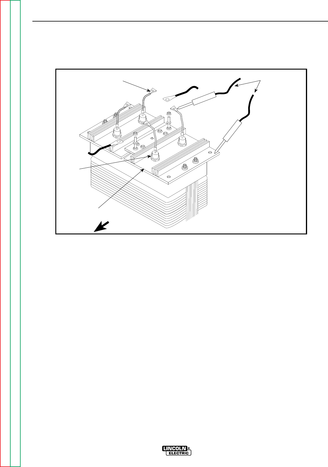
Return to Section TOC Return to Section TOC Return to Section TOC Return to Section TOC
Return to Master TOC Return to Master TOC Return to Master TOC Return to Master TOC
TROUBLESHOOTING & REPAIR
F-30 F-30
RANGER 9 RANGER 9
OUTPUT RECTIFIER BRIDGE TEST (continued)
FIGURE F.5 – LOCATION OF OUTPUT RECTIFIER LEADS
Ohmmeter Probes
+
Pigtail
Diode
Output rectifier
Bridge Assembly Machine Front
-
TEST PROCEDURE
1. Remove the spark plug wires to prevent
accidental engine kickback or starting.
2. WIth the 5/16” nut driver, remove the 6
sheet metal screws from the case top.
3. Remove the rubber gasket (cover seal) from
the lift bale.
4. Remove the fuel cap. The rubber gasket for
the fill tube will come off with the case top.
5. Remove the case top, then replace the
fuel cap.
6. With the 5/16” nut driver, remove the 5
screws holding the right case side.
7. Remove the right case side by lifting up and
out.
8. Conduct the test with the gasoline engine
OFF.
9. Locate the Output Rectifier Bridge behind
the machine case front.
10. With the 1/2” socket wrench, remove the
nuts and washers holding the diode bridge
pigtails and the heavy current-carrying
leads to the studs located in the middle of
the rectifier assembly. Note their locations
and the order of fasteners for reassembly.
11. Electrically isolate the diode pigtails by
bending them back into “free air.”
12. With an ohmmeter or diode tester, check
each of the four diodes from their pigtails
to their respective heat sinks. See Figure
F.5.
13. Reverse the tester leads and check the
diodes again. Diodes should have a low
resistance in one polarity and a very high
resistance in the opposite polarity.
14. Replace any “shorted” or “open” diode as
the tests indicate.
15. Reconnect the diode pigtails and heavy
leads to their respective studs.
16. Reinstall the case side, case top, fuel cap,
lift bale gasket and spark plug wires.

Return to Section TOC Return to Section TOC Return to Section TOC Return to Section TOC
Return to Master TOC Return to Master TOC Return to Master TOC Return to Master TOC
TROUBLESHOOTING & REPAIR
F-31 F-31
RANGER 9 RANGER 9
WARNING
CHARGING CIRCUIT TEST
Service and repair should be performed by only Lincoln Electric factory trained personnel.
Unauthorized repairs performed on this equipment may result in danger to the technician or
machine operator and will invalidate your factory warranty. For your safety and to avoid elec-
trical shock, please observe all safety notes and precautions detailed throughout this manual.
If for any reason you do not understand the test procedures or are unable to perform the
test/repairs safely, contact the Lincoln Electric Service Department for electrical trou-
bleshooting assistance before you proceed. Call 216-383-2531 or 1-800-833-9353 (WELD).
TEST DESCRIPTION
This test will determine if the Flywheel Alternator, Regulator, and associated circuitry are
functioning properly.
MATERIALS NEEDED
Volt/Ohmmeter
5/16” Nut driver
Wiring Diagram
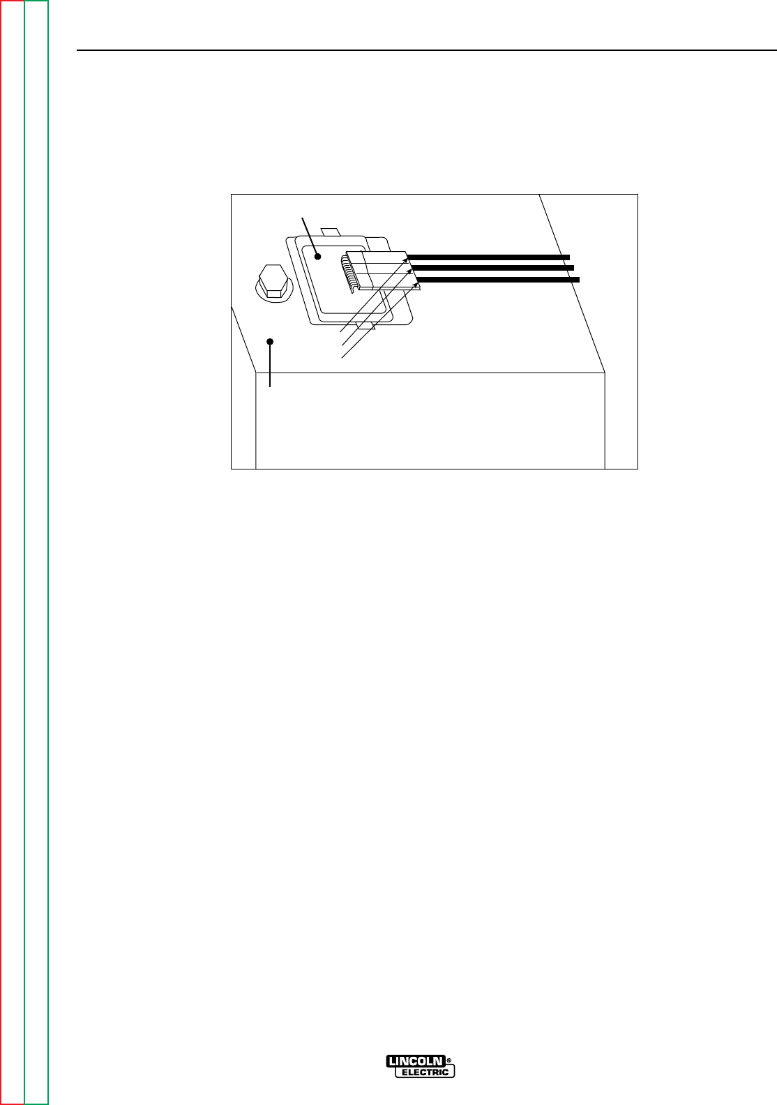
Return to Section TOC Return to Section TOC Return to Section TOC Return to Section TOC
Return to Master TOC Return to Master TOC Return to Master TOC Return to Master TOC
TROUBLESHOOTING & REPAIR
F-32 F-32
RANGER 9 RANGER 9
CHARGING CIRCUIT TEST (continued)
FIGURE F.6 – LOCATION OF VOLTAGE REGULATOR
AC Lead
DC Lead
AC Lead
Voltage Regulator
Engine Cooling
Shroud
TEST PROCEDURE
1. Start the engine and run it at high idle
(3700 RPM).
2. Set the voltmeter for AC volts and place
one meter probe on each of the two out-
side leads that attach to the engine voltage
regulator. See FIgure F.6 for location.
Check for 52 VAC at the voltage regulator.
3. If the AC voltage is low or not present, the
engine flywheel alternator may be faulty.
This is an engine problem; consult your
local engine repair facility.
4. If the voltage reading is correct, then check
the output of the voltage regulator to deter-
mine the charging voltage for the battery.
Run the engine at high idle (3700 RPM).
Set the voltmeter for DC volts and place
one meter probe on any good ground. See
Figure F.6. Check for 13-15 VDC.
5. If the DC voltage reading is incorrect or not
present, the voltage regulator may be
faulty. Replace the entire voltage regulator
module.
6. If the DC voltage reading is correct, check
the associated wiring and circuitry. See
the Wiring Diagram.

Return to Section TOC Return to Section TOC Return to Section TOC Return to Section TOC
Return to Master TOC Return to Master TOC Return to Master TOC Return to Master TOC
TROUBLESHOOTING & REPAIR
F-33 F-33
RANGER 9 RANGER 9
WARNING
ENGINE THROTTLE ADJUSTMENT TEST
Service and repair should be performed by only Lincoln Electric factory trained personnel.
Unauthorized repairs performed on this equipment may result in danger to the technician or
machine operator and will invalidate your factory warranty. For your safety and to avoid elec-
trical shock, please observe all safety notes and precautions detailed throughout this manual.
If for any reason you do not understand the test procedures or are unable to perform the
test/repairs safely, contact the Lincoln Electric Service Department for electrical trou-
bleshooting assistance before you proceed. Call 216-383-2531 or 1-800-833-9353 (WELD).
TEST DESCRIPTION
If the machine output is low, this test will determine whether the gasoline engine is operating
at the correct speed (RPM) during both HIGH and LOW idle conditions. Directions for adjust-
ing the throttle to the correct RPM are given.
MATERIALS NEEDED
5/16” Nut driver
3/8” open end or box wrench
Strobe-tach, frequency counter, oscilloscope, or vibratach
Black or red marking pencil
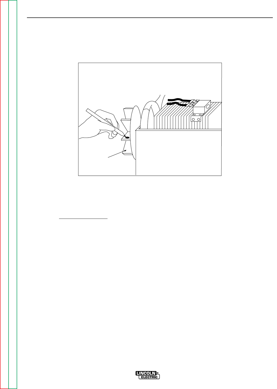
TROUBLESHOOTING & REPAIR
F-34 F-34
RANGER 9 RANGER 9
Return to Section TOC Return to Section TOC Return to Section TOC Return to Section TOC
Return to Master TOC Return to Master TOC Return to Master TOC Return to Master TOC
ENGINE THROTTLE ADJUSTMENT TEST (continued)
FIGURE F.7 – BLOWER PADDLE MARKED FOR STROBE-TACH METHOD
Blower Paddle
TEST PROCEDURE
This test can be conducted by any one of four
methods.
Strobe-tach Method:
1. With the 5/16” nut driver, remove the 6
sheet metal screws from the case top.
2. Remove the rubber gasket (cover seal) from
the lift bale.
3. Remove the fuel cap. The rubber gasket for
the fill tube will come off with the case top.
4. Remove the case top, then replace the
fuel cap.
5. Conduct this procedure with the gasoline
engine OFF.
6. Remove the spark plug wires to prevent
accidental engine kickback or starting.
7. With the black or red marking pencil, place
a mark on one of the blower paddles. See
Figure F.7 for location.
8. Connect the strobe-tach according the
manufacturer’s instructions.
9. Reconnect the spark plug wires and start
the engine. Direct the strobe-tach light on
the blower paddle and synchronize it to
the rotating mark.
10. With the machine at HIGH IDLE the tach
should read between 3700 and 3750 RPM.
With the machine at LOW IDLE the tach
should read between 2150 and 2250 RPM.
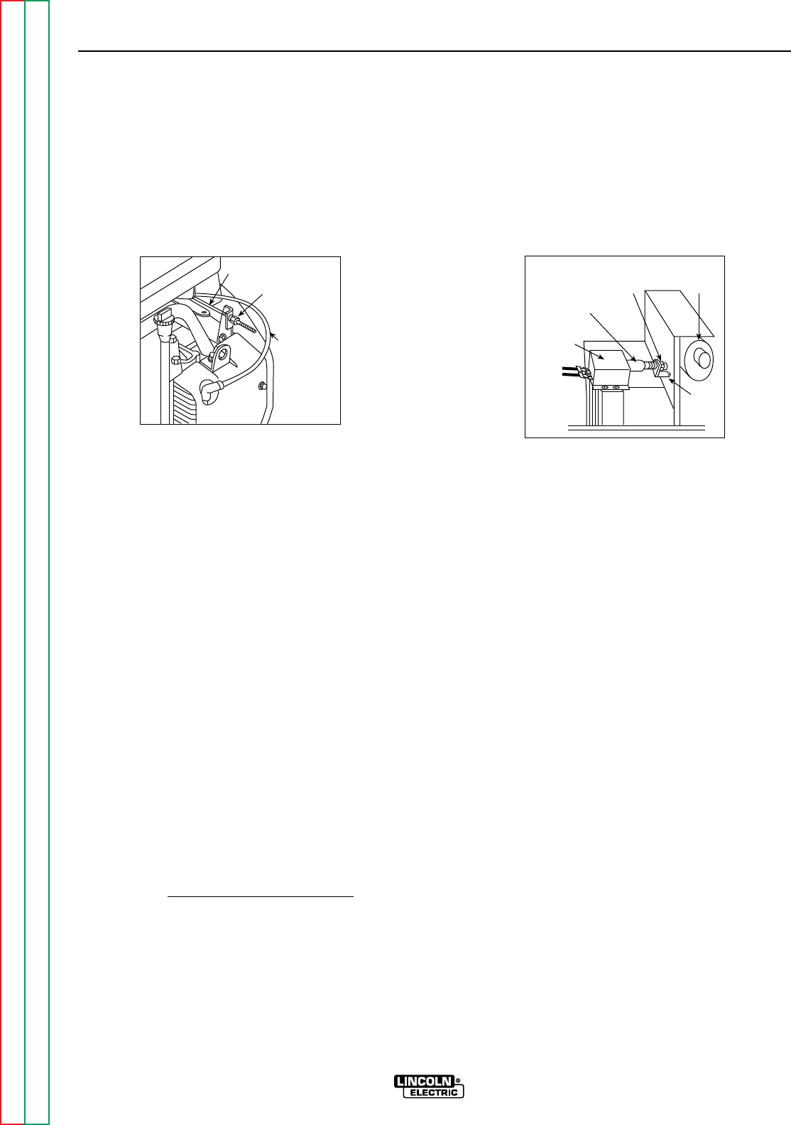
Return to Section TOC Return to Section TOC Return to Section TOC Return to Section TOC
Return to Master TOC Return to Master TOC Return to Master TOC Return to Master TOC
TROUBLESHOOTING & REPAIR
F-35 F-35
RANGER 9 RANGER 9
ENGINE THROTTLE ADJUSTMENT TEST (continued)
Throttle Linkage
Choke Cable
3/8" High Idle
Adjustment Nut
Housing
Solenoid
3/8" Low Idle
Adjustment Nut Muffler
Rod
11. If either of the readings is incorrect, adjust
the throttle as follows:
Adjust HIGH IDLE: Use the 3/8” wrench to
turn the spring-loaded adjustment nut.
See Figure F.8 for location of the adjust-
ment nut. Turn the nut clockwise to
increase HIGH IDLE speed. Adjust the
speed until the tach reads between 3700
and 3750 RPM.
Adjust LOW IDLE: First make sure there is
no load on the machine. Set the IDLE
switch to AUTO and wait for the engine to
change to low idle speed. Use the 3/8”
wrench to adjust the solenoid nut, which
changes the amount of throw in the throttle
lever arm. See Figure F.9 for location of the
adjustment nut. Adjust the nut until the
tach reads between 2150 and 2250 RPM.
Frequency Counter Method
1. Plug the frequency counter into one of the
115 VAC auxiliary receptacles.
2. Start the engine and check the frequency
counter. At HIGH IDLE (3700 RPM), the
counter should read 63 Hz. At LOW IDLE
(2200 RPM), the counter should read 37
Hz. Note that these are median measure-
ments; hertz readings may vary slightly
above or below.
3. If either of the readings is incorrect, adjust
the throttle as follows:
Adjust HIGH IDLE: Use the 3/8” wrench to
turn the spring-loaded adjustment nut.
See Figure F.8 for location of the adjust-
ment nut. Turn the nut clockwise to in-
crease HIGH IDLE speed. Adjust the
speed until the frequency reads 63 Hz.
Adjust LOW IDLE: First make sure there is
no load on the machine. Set the IDLER
switch to AUTO and wait for the engine to
change to low idle speed. Use the 3/8”
wrench to adjust the solenoid nut, which
changes the amount of throw in the throttle
lever arm. See Figure F.9 for location of the
adjustment nut. Adjust the nut until the fre-
quency reads 37 Hz.
FIGURE F.8
HIGH IDLE ADJUSTMENT NUT FIGURE F.9
LOW IDLE ADJUSTMENT NUT

Return to Section TOC Return to Section TOC Return to Section TOC Return to Section TOC
Return to Master TOC Return to Master TOC Return to Master TOC Return to Master TOC
TROUBLESHOOTING & REPAIR
F-36 F-36
RANGER 9 RANGER 9
ENGINE THROTTLE ADJUSTMENT TEST (continued)
Oscilloscope Method:
1. Connect the oscilloscope to the 115 VAC
receptacle, according to the manufactur-
er’s instructions. At 3700 RPM, the wave-
form should exhibit a period of 15.8 mil-
liseconds. At 2200 RPM, the waveform
should exhibit a period of 27.02 millisec-
onds. Refer to NORMAL OPEN CIRCUIT
VOLTAGE WAVEFORM (115 VAC SUPPLY)
HIGH IDLE – NO LOAD in this section of
the manual.
2. If either waveform periods is incorrect,
adjust the throttle as follows:
Adjust HIGH IDLE: Use the 3/8” wrench to
turn the spring-loaded adjustment nut.
See Figure F.8 for location of the adjust-
ment nut. Adjust the speed until the period
is 15.8 mililseconds.
Adjust LOW IDLE: First make sure there is
no load on the machine. Set the IDLER
switch to AUTO and wait for the engine to
change to low idle speed. Use the 3/8”
wrench to adjust the solenoid nut, which
changes the amount of throw in the throttle
lever arm. See Figure F.9 for location of the
adjustment nut. Adjust the speed until the
period is 27.02 milliseconds.
Vibratach Method:
1. Place the vibratach as close to the engine
as possible. With the machine case top
removed, the top of the air cleaner is the
best location.
2. Start the engine and observe the whip
handle of the vibratach. At HIGH IDLE
(3700 RPM), the whip handle should
exhibit maximum oscillation. At LOW IDLE
(2200 RPM), the whip handle should
exhibit minimum oscillation. Note that
these are median measurements; vibrat-
ach readings may vary slightly above or
below.
3. If either of the vibratach indications is
incorrect, adjust the throttle as follows:
Adjust HIGH IDLE: Use the 3/8” wrench to
turn the spring-loaded adjustment nut.
See Figure F.8 for location of the adjust-
ment nut. Turn the nut clockwise to
increase HIGH IDLE speed. Adjust the
speed until the vibratach whip handle
exhibits maximum oscillation at 3700 RPM.
Adjust LOW IDLE: First make sure that
there is no load on the machine. Set the
IDLER switch to AUTO and wait for the
engine to change to low idle speed. Use
the 3/8” wrench to adjust the solenoid nut,
which changes the amount of throw in the
throttle lever arm. See Figure F.9 for loca-
tion of the adjustment nut. Adjust the
speed until the vibratach whip handle
exhibits minimum oscillation at 2150 to
2250 RPM.
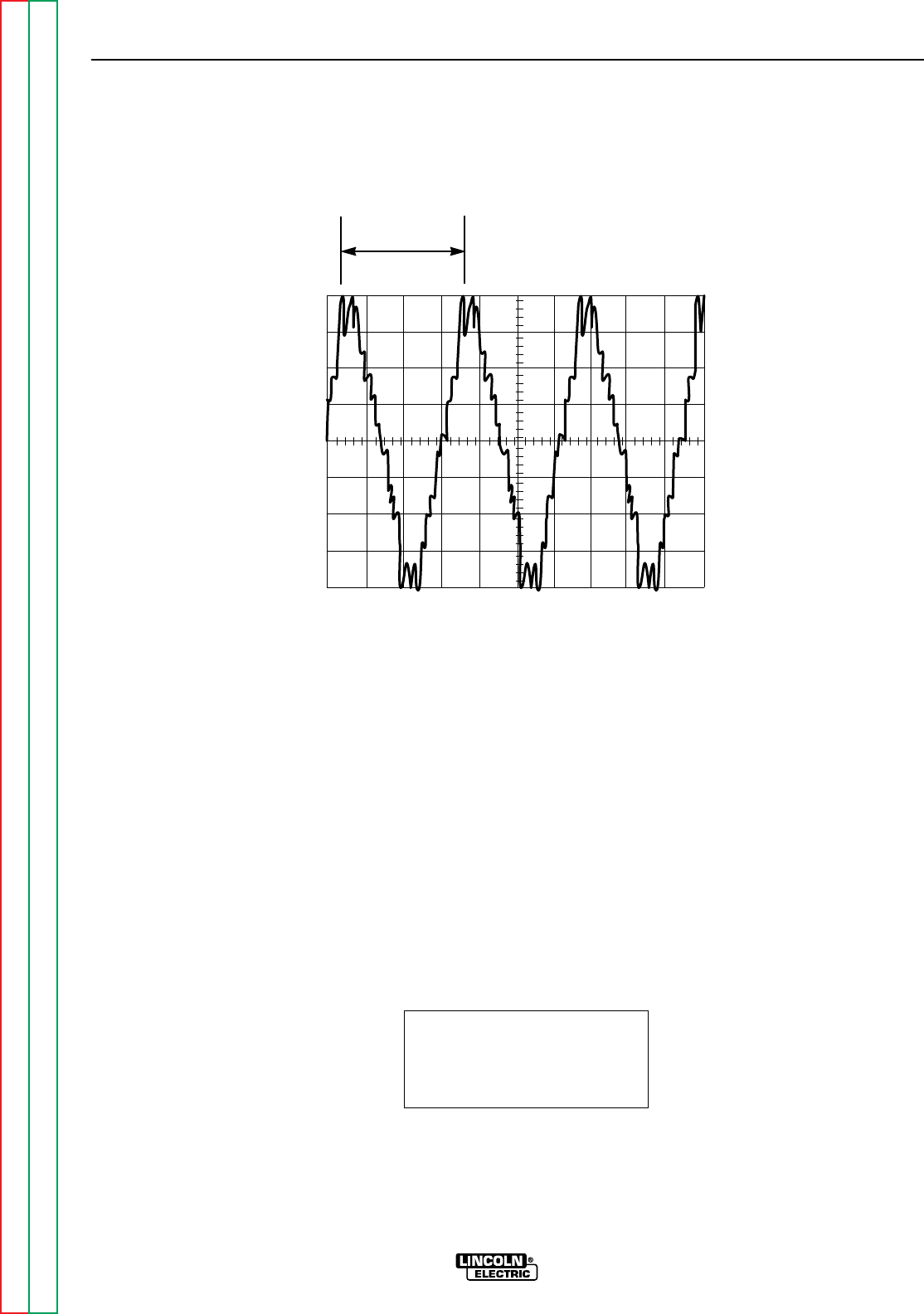
Return to Section TOC Return to Section TOC Return to Section TOC Return to Section TOC
Return to Master TOC Return to Master TOC Return to Master TOC Return to Master TOC
TROUBLESHOOTING & REPAIR
F-37 F-37
RANGER 9 RANGER 9
This is the typical auxiliary output
voltage generated from a properly
operating machine. Note that each
vertical division represents 50 volts
and that each horizontal division rep-
resents 5 milliseconds in time.
Note: Scope probes connected at
machine 115VAC receptacle.
SCOPE SETTINGS
Volts/Div.....................50V/Div.
Horizontal Sweep.....5 ms/Div.
Coupling ............................DC
Trigger.........................Internal
NORMAL OPEN CIRCUIT VOLTAGE WAVEFORM (115VAC SUPPLY)
HIGH IDLE – NO LOAD – OUTPUT CONTROL AT MAXIMUM
CH1
0 volts
5 ms
50 volts
15.8 ms

Return to Section TOC Return to Section TOC Return to Section TOC Return to Section TOC
Return to Master TOC Return to Master TOC Return to Master TOC Return to Master TOC
TROUBLESHOOTING & REPAIR
F-38 F-38
RANGER 9 RANGER 9
This is the typical CV output voltage
generated from a properly operating
machine. Note that each vertical
division represents 20 volts and that
each horizontal division represents 5
milliseconds in time. The machine
was loaded with a resistance grid
bank.
Note: Scope probes connected at
machine output terminals.
SCOPE SETTINGS
Volts/Div.....................20V/Div.
Horizontal Sweep.....5 ms/Div.
Coupling ............................DC
Trigger.........................Internal
MACHINE LOADED TO 250 AMPS AT 25VDC
TYPICAL DC WELD OUTPUT VOLTAGE WAVEFORM (CV MODE HIGH TAP)
MACHINE LOADED
CH1
0 volts
5 ms
20 volts
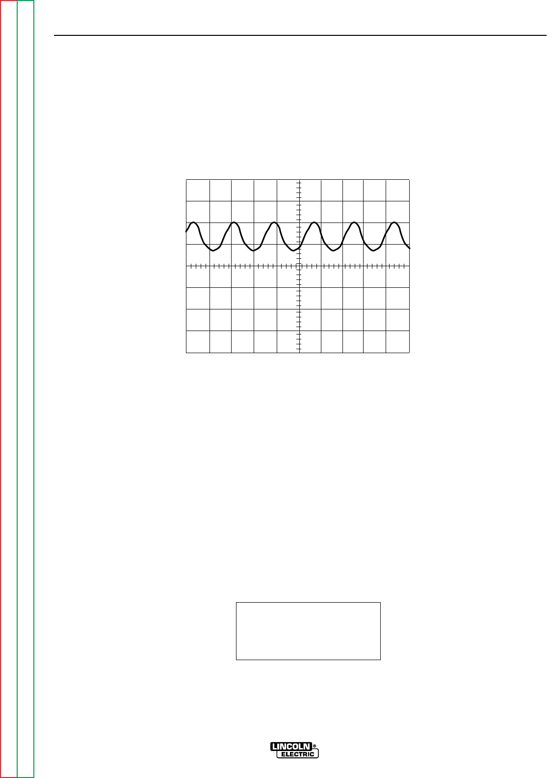
Return to Section TOC Return to Section TOC Return to Section TOC Return to Section TOC
Return to Master TOC Return to Master TOC Return to Master TOC Return to Master TOC
TROUBLESHOOTING & REPAIR
F-39 F-39
RANGER 9 RANGER 9
This is the typical DC output voltage
generated from a properly operating
machine. Note that each vertical
division represents 20 volts and that
each horizontal division represents 5
milliseconds in time. The machine
was loaded with a resistance grid
bank.
Note: Scope probes connected at
machine output terminals.
SCOPE SETTINGS
Volts/Div.....................20V/Div.
Horizontal Sweep.....5 ms/Div.
Coupling ............................DC
Trigger.........................Internal
TYPICAL DC WELD OUTPUT VOLTAGE WAVEFORM
MACHINE LOADED
CH1
0 volts
5 ms
20 volts
MACHINE LOADED TO 250 AMPS AT 25 VDC
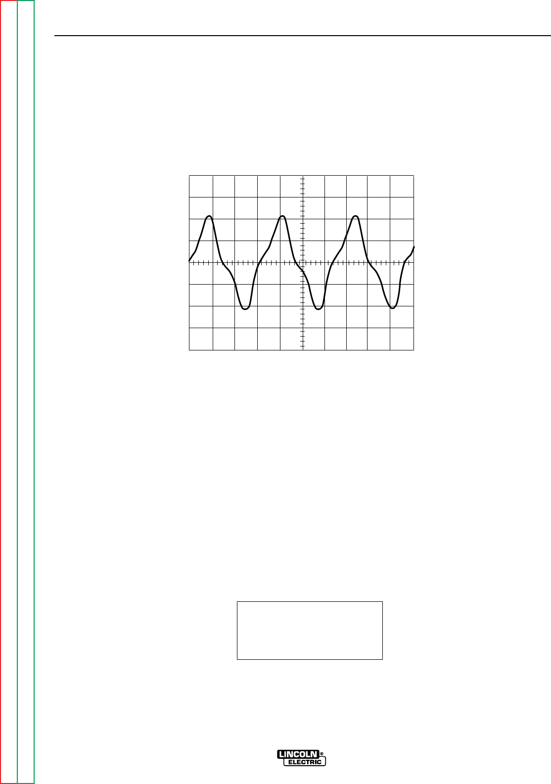
Return to Section TOC Return to Section TOC Return to Section TOC Return to Section TOC
Return to Master TOC Return to Master TOC Return to Master TOC Return to Master TOC
TROUBLESHOOTING & REPAIR
F-40 F-40
RANGER 9 RANGER 9
This is the typical AC output voltage
generated from a properly operating
machine. Note that each vertical
division represents 20 volts and that
each horizontal division represents 5
milliseconds in time. The machine
was loaded with a resistance grid
bank.
Note: Scope probes connected at
machine output terminals.
SCOPE SETTINGS
Volts/Div.....................20V/Div.
Horizontal Sweep.....5 ms/Div.
Coupling ............................DC
Trigger.........................Internal
MACHINE LOADED TO 250 AMPS AT 25VDC
TYPICAL AC WELD OUTPUT VOLTAGE WAVEFORM
MACHINE LOADED
CH1
0 volts
5 ms
20 volts

Return to Section TOC Return to Section TOC Return to Section TOC Return to Section TOC
Return to Master TOC Return to Master TOC Return to Master TOC Return to Master TOC
TROUBLESHOOTING & REPAIR
F-41 F-41
RANGER 9 RANGER 9
This is NOT the typical DC (+) output
voltage waveform. One output diode
is not functioning. Note the “gap” in
the waveform. One output diode was
disconnected to simulate an open or
non-functioning output diode. Each
vertical division represents 50 volts
and each horizontal division repre-
sents 5 milliseconds in time.
Note: Scope probes connected at
machine output terminals.
SCOPE SETTINGS
Volts/Div.....................50V/Div.
Horizontal Sweep.....5 ms/Div.
Coupling ............................DC
Trigger.........................Internal
ABNORMAL OPEN CIRCUIT DC WELD VOLTAGE WAVEFORM
HIGH IDLE - NO LOAD - OUTPUT CONTROL AT MAXIMUM
ONE OUTPUT DIODE NOT FUNCTIONING
CH1
0 volts
5 ms
50 volts

Return to Section TOC Return to Section TOC Return to Section TOC Return to Section TOC
Return to Master TOC Return to Master TOC Return to Master TOC Return to Master TOC
TROUBLESHOOTING & REPAIR
F-42 F-42
RANGER 9 RANGER 9
This is NOT the typical CV output
voltage waveform. The capacitor
bank is not functioning. Note the
“ripple” in the waveform. The capac-
itor bank was disconnected to simu-
late an open or non-functioning
capacitor bank. Each vertical divi-
sion represents 50 volts and each
horizontal division represents 5 mil-
liseconds in time.
Note: Scope probes connected at
machine output terminals.
SCOPE SETTINGS
Volts/Div.....................50V/Div.
Horizontal Sweep.....5 ms/Div.
Coupling ............................DC
Trigger.........................Internal
ABNORMAL OPEN CIRCUIT WELD VOLTAGE WAVEFORM
(HIGH CV MODE)
HIGH IDLE – NO LOAD – OUTPUT CONTROL AT MAXIMUM
OUTPUT CAPACITOR BANK NOT FUNCTIONING
CH1
0 volts
5 ms
50 volts

Return to Section TOC Return to Section TOC Return to Section TOC Return to Section TOC
Return to Master TOC Return to Master TOC Return to Master TOC Return to Master TOC
TROUBLESHOOTING & REPAIR
F-43 F-43
RANGER 9 RANGER 9
This is the typical CV output voltage
generated from a properly operating
machine. Note that each vertical
division represents 20 volts and that
each horizontal division represents 5
milliseconds in time.
Note: Scope probes connected at
machine output terminals.
SCOPE SETTINGS
Volts/Div.....................20V/Div.
Horizontal Sweep.....5 ms/Div.
Coupling ............................DC
Trigger.........................Internal
NORMAL OPEN CIRCUIT WELD VOLTAGE WAVEFORM (HIGH CV MODE)
HIGH IDLE – NO LOAD – OUTPUT CONTROL AT MAXIMUM
CH1
0 volts
5 ms
20 volts
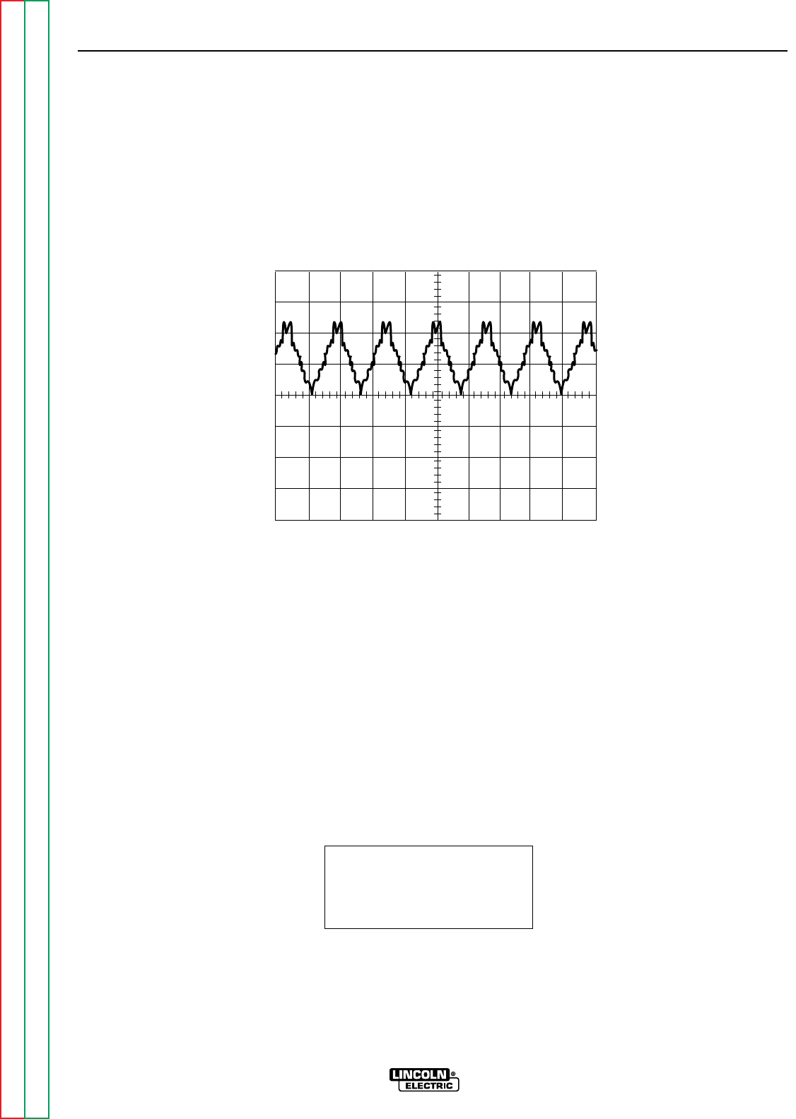
Return to Section TOC Return to Section TOC Return to Section TOC Return to Section TOC
Return to Master TOC Return to Master TOC Return to Master TOC Return to Master TOC
TROUBLESHOOTING & REPAIR
F-44 F-44
RANGER 9 RANGER 9
SCOPE SETTINGS
Volts/Div.....................50V/Div.
Horizontal Sweep.....5 ms/Div.
Coupling ............................DC
Trigger.........................Internal
CH1
0 volts
5 ms
50V
This is the typical DC output voltage
generated from a properly operating
machine. Note that each vertical
division represents 50 volts and that
each horizontal division represents 5
milliseconds in time.
Note: Scope probes connected at
machine output terminals.
NORMAL OPEN CIRCUIT DC WELD VOLTAGE WAVEFORM
HIGH IDLE – NO LOAD – OUTPUT CONTROL AT MAXIMUM
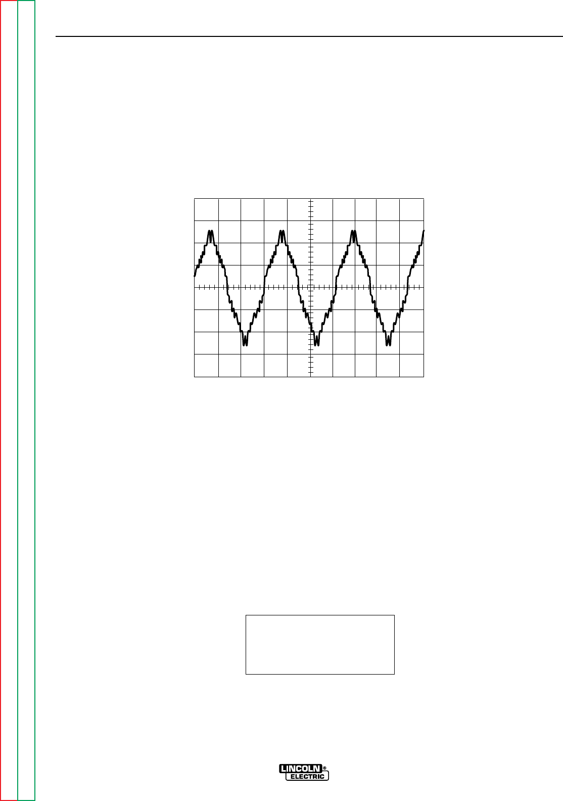
Return to Section TOC Return to Section TOC Return to Section TOC Return to Section TOC
Return to Master TOC Return to Master TOC Return to Master TOC Return to Master TOC
TROUBLESHOOTING & REPAIR
F-45 F-45
RANGER 9 RANGER 9
CH1
0 volts
5 ms
50 volts
SCOPE SETTINGS
Volts/Div.....................50V/Div.
Horizontal Sweep.....5 ms/Div.
Coupling ............................DC
Trigger.........................Internal
This is the typical AC output voltage
generated from a properly operating
machine. Note that each vertical
division represents 50 volts and that
each horizontal division represents 5
milliseconds in time.
Note: Scope probes connected at
machine output terminals.
NORMAL OPEN CIRCUIT AC WELD VOLTAGE WAVEFORM
HIGH IDLE – NO LOAD – OUTPUT CONTROL AT MAXIMUM

Return to Section TOC Return to Section TOC Return to Section TOC Return to Section TOC
Return to Master TOC Return to Master TOC Return to Master TOC Return to Master TOC
TROUBLESHOOTING & REPAIR
F-46 F-46
RANGER 9 RANGER 9
BRUSH REMOVAL AND REPLACEMENT
WARNING
Service and repair should be performed by only Lincoln Electric factory trained person-
nel. Unauthorized repairs performed on this equipment may result in danger to the tech-
nician or machine operator and will invalidate your factory warranty. For your safety and
to avoid electrical shock, please observe all safety notes and precautions detailed
throughout this manual.
If for any reason you do not understand the test procedures or are unable to perform the
test/repairs safely, contact the Lincoln Electric Service Department for electrical trou-
bleshooting assistance before you proceed. Call 216-383-2531 or 1-800-833-9353
(WELD).
DESCRIPTION
The following procedure will aid the technician in accessing the generator brushes for
maintenance or replacement.
MATERIALS NEEDED
5/16” Nut driver
5/16” Open end wrench
3/8” Wrench
7/16” Wrench
Slot head screw driver
Needle nose pliers

Return to Section TOC Return to Section TOC Return to Section TOC Return to Section TOC
Return to Master TOC Return to Master TOC Return to Master TOC Return to Master TOC
TROUBLESHOOTING & REPAIR
F-47 F-47
RANGER 9 RANGER 9
BRUSH REMOVAL AND REPLACEMENT (continued)
PROCEDURE
1. Remove the spark plug wires.
2. With the 5/16” nut driver, remove the 6
sheet metal screws from the case top.
3. Remove the rubber gasket (cover seal)
from the lift bale.
4. Remove the fuel cap. The rubber gasket
for the fill tube with come off with the case
top.
5. Remove the case top, then reinstall the
fuel cap.
6. WIth the 5/16” nut driver, remove the 5
screws holding the right case side.
7. Remove the right case side by lifting up
and out.
8. With the 3/8” wrench, remove the screws
holding the right stator cover. This will
expose the brush holder assembly.
9. With the needle nose pliers, gently remove
the blue and the red wires from the
brushes. See Figure F.10.
10. With the 7/16” wrench, remove the brush
holder assembly bracket from the stator
frame.
11. With the 5/16” open end wrench, remove
the two screws that secure the brush hold-
er assembly to the bracket. Slide the
brush holder assembly out of the bracket.
12. To change the brushes, use the slot head
screw driver to pop off the plastic retainer
on the back of the brush holder assembly.
13. Remove the old brushes and insert the
new ones. One corner of the terminal clip
is beveled so that the brush can go in only
one way.
14. Snap the plastic retainer back onto the
brush holder. The brushes may need
some repositioning; wiggle them slightly to
help them seat properly on the slip rings.
15. To reinstall the brushes, depress the
spring-loaded brushes into the holder and
slip a suitable non-metallic, fairly stiff
retainer through the slots at the top and
bottom of the holder. A cable tie works
well; see Figure F.10. This will hold the
brushes up so that you can easily install
the holder.
16. Slide the brush holder assembly back into
the bracket and, with the 5/16” open end
wrench, install the two screws that hold it
in place.
17. With the 7/16” wrench, install the brush
holder assembly bracket to the stator
frame.
18. Slowly remove the non-metallic retainer
from the brush holder and let the brushes
snap back against the slip rings.
19. With the needle nose pliers, connect the
red and the black wires to the appropriate
terminals on the brushes. The red wire is
inboard.
20. Check the wire connections for clearance
and tightness.
21. Reinstall the right stator cover, case side,
fuel cap, lift bale gasket, case top, and
spark plug wires.
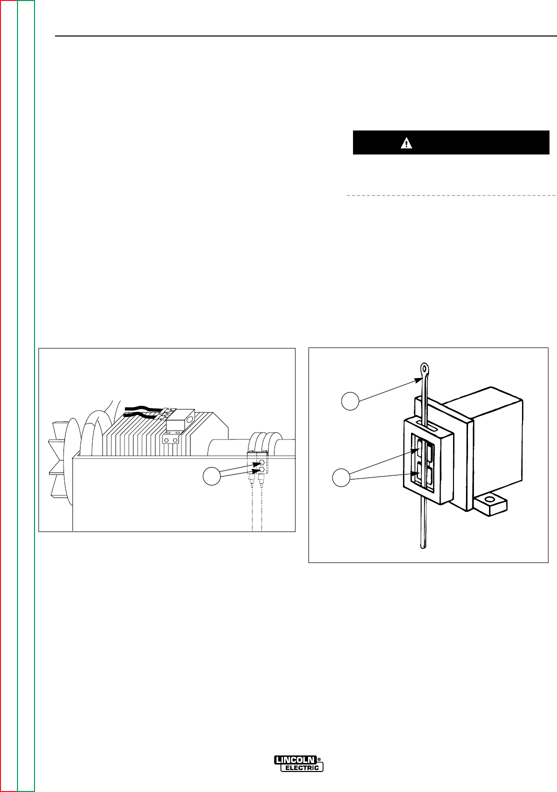
Return to Section TOC Return to Section TOC Return to Section TOC Return to Section TOC
Return to Master TOC Return to Master TOC Return to Master TOC Return to Master TOC
TROUBLESHOOTING & REPAIR
F-48 F-48
RANGER 9 RANGER 9
SLIP RINGS
A slight amount of darkening and wear of the
slip rings and brushes is normal. Brushes
should be inspected when a general overhaul is
necessary. If brushes are to be replaced, clean
slip rings with a fine emery paper. Do not attempt to polish slip rings while engine
is running.
BRUSH REMOVAL AND REPLACEMENT (continued)
CAUTION
FIGURE F.10 - BRUSH LEADS/BRUSHES RETAINED WITH CABLE TIE
1
1
2
1. BRUSH HOLDER ASSEMBLY BRACKET BOLTS
1. CABLE TIE
2. BRUSHES

Return to Section TOC Return to Section TOC Return to Section TOC Return to Section TOC
Return to Master TOC Return to Master TOC Return to Master TOC Return to Master TOC
TROUBLESHOOTING & REPAIR
F-49 F-49
RANGER 9 RANGER 9
WARNING
FIELD CAPACITOR AND/OR RECTIFIER BRIDGE REMOVAL
AND REPLACEMENT
Service and repair should be performed by only Lincoln Electric factory trained personnel.
Unauthorized repairs performed on this equipment may result in danger to the technician or
machine operator and will invalidate your factory warranty. For your safety and to avoid elec-
trical shock, please observe all safety notes and precautions detailed throughout this manu-
al.
If for any reason you do not understand the test procedures or are unable to perform the
test/repairs safely, contact the Lincoln Electric Service Department for electrical trou-
bleshooting assistance before you proceed. Call 216-383-2531 or 1-800-833-9353 (WELD).
DESCRIPTION
The following procedure will aid the technician in accessing and removing the field capacitor
and rectifier bridge for maintenance or replacement of either component.
MATERIALS NEEDED
5/16” Nut driver
Jumper wire with alligator clips on each end for discharging the field capacitor
Slot head screw driver
Needle nose pliers
Wiring Diagram
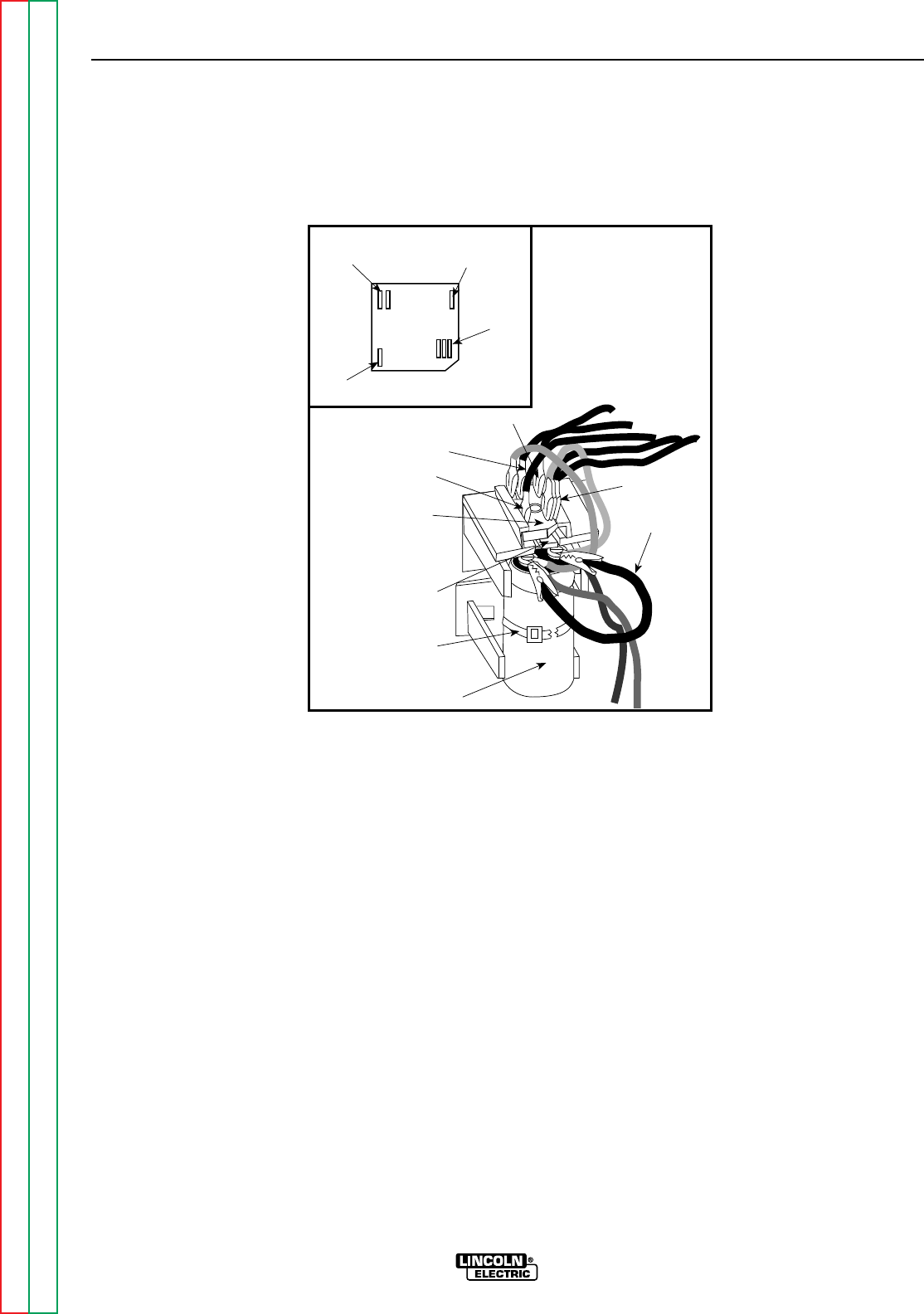
Return to Section TOC Return to Section TOC Return to Section TOC Return to Section TOC
Return to Master TOC Return to Master TOC Return to Master TOC Return to Master TOC
TROUBLESHOOTING & REPAIR
F-50 F-50
RANGER 9 RANGER 9
FIELD CAPACITOR AND/OR RECTIFIER BRIDGE REMOVAL
AND REPLACEMENT (continued)
FIGURE F.11
RECTIFIER BRIDGE LOCATION AND DISCHARGING THE FIELD CAPACITOR
Retaining
Tab
Field
Bridge
Rectifier Jumper
7
9
Capacitor
201
201A
200
200A
200B
Cable Tie
201
201A
200
200A
200B
7
9+
_AC
AC
PROCEDURE
1. Remove the engine spark plug wires.
2. With the 5/16” nut driver, remove the 6
sheet metal screws from the case top.
3. Remove the rubber gasket (cover seal) from
the lift bale.
4 Remove the fuel cap. The rubber gasket for
the fill tube will come off with the case top.
5. Remove the case top, then reinstall the
fuel cap.
6. With the 5/16” nut driver, remove the 5
screws holding the right case side.
7. Remove the right case side by lifting up and
out.
8. Discharge the field capacitor by connecting
the jumper wire clips on the black and the
red wire terminals on the top of the capac-
itor. See Figure F.11 for location. Leave the
clips on for at least 5 seconds, then
remove.
9. Both the capacitor and the rectifier bridge
are mounted in a molded plastic holder.
To remove it, pull out on the top of the
holder, then slide it upward.
10. Cut the cable tie and then snap the
capacitor out of the assembly.
11. Loosen the two screws on the top of the
capacitor. Lead 200 attaches to the posi-
tive (+) terminal. Lead 201 attaches to the
negative terminal (-) terminal.
12. To install the capacitor, reattach the leads
to their respective terminals [200 to posi-
tive (+); 201 to negative (-) ] and tighten
the screws. Snap the capacitor back into
the molded plastic holder and slide the
holder back into position in the panel.
Replace the cable tie.
13. Reinstall the case side, fuel cap, lift bale
gasket, case top, and spark plug wires.

Return to Section TOC Return to Section TOC Return to Section TOC Return to Section TOC
Return to Master TOC Return to Master TOC Return to Master TOC Return to Master TOC
TROUBLESHOOTING & REPAIR
F-51 F-51
RANGER 9 RANGER 9
FIELD CAPACITOR AND/OR RECTIFIER BRIDGE REMOVAL
AND REPLACEMENT (continued)
PROCEDURE - RECTIFIER BRIDGE
REMOVAL AND REPLACEMENT
1. To remove the rectifier bridge, first you will
have to remove the field capacitor. Follow
Steps 1 - 10 above.
2. Depress the retainer clip on the molded
plastic holder and slide the rectifier bridge
out.
3. With the needle nose pliers, gently remove
the 6 wires from the rectifier bridge.
4. Replace the wires to their appropriate loca-
tions on the new rectifier bridge (See the
Wiring Diagram.):
Lead #200 and #200A are piggybacked on
the positive (+) terminal. Depending on the
bridge used, this corner may be beveled
and/or marked with a + sign.
Lead #201 and #201A are piggybacked on
the negative (-) terminal, which will always
be located diagonally across from the pos-
itive (+) terminal.
The two leads #7 and #9 are the AC side of
the bridge and attach to the other two cor-
ners. Either lead can go on either terminal.
5. Slide the bridge back into the molded plas-
tic holder until the retainer clip snaps it
securely in place. Snap the capacitor back
into the holder and then slide the unit back
into position in the panel. Replace the cable
tie.
6. Check that the leads are not grounded and
for clearance and tightness.
7. Reinstall the case side, fuel cap, lift bale
gasket, and case top.

Return to Section TOC Return to Section TOC Return to Section TOC Return to Section TOC
Return to Master TOC Return to Master TOC Return to Master TOC Return to Master TOC
TROUBLESHOOTING & REPAIR
F-52 F-52
RANGER 9 RANGER 9
WARNING
PRINTED CIRCUIT BOARD REMOVAL
AND REPLACEMENT
Service and repair should be performed by only Lincoln Electric factory trained personnel.
Unauthorized repairs performed on this equipment may result in danger to the technician or
machine operator and will invalidate your factory warranty. For your safety and to avoid elec-
trical shock, please observe all safety notes and precautions detailed throughout this man-
ual.
If for any reason you do not understand the test procedures or are unable to perform the
test/repairs safely, contact the Lincoln Electric Service Department for electrical trou-
bleshooting assistance before you proceed. Call 216-383-2531 or 1-800-833-9353 (WELD).
DESCRIPTION
The following procedure will aid the technician in removing the printed circuit board for main-
tenance or replacement.
MATERIALS NEEDED
5/16” Nut driver
1/4” Nut driver
Diagonal cutters
Wiring Diagram
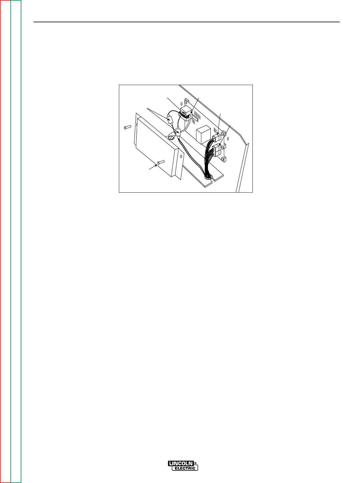
Return to Section TOC Return to Section TOC Return to Section TOC Return to Section TOC
Return to Master TOC Return to Master TOC Return to Master TOC Return to Master TOC
TROUBLESHOOTING & REPAIR
F-53 F-53
RANGER 9 RANGER 9
PRINTED CIRCUIT BOARD REMOVAL AND REPLACEMENT
(continued)
FIGURE F.12 - PRINTED CIRCUIT BOARD LOCATION
Current
Sensor
In Line
Connectors
Current
Sensing Leads
12 Pin
Molex Plug
6 Pin
Molex Plug
5/16"
Screw (2)
PROCEDURE
Before starting the following procedure, refer to
the topic “PC Board Troubleshooting
Procedures” at the beginning of this section.
1. Remove the engine spark plug wires.
2. With the 5/16” nut driver, remove the 6
sheet metal screws from the case top.
3. Remove the rubber gasket (cover seal) from
the lift bale.
4. Remove the fuel cap. The rubber gasket for
the fill tube will come off with the case top.
5. Remove the case top, then reinstall the
fuel cap.
6. With the 5/16” nut driver, remove the 5
screws holding the right case side.
7. Remove the right case side by lifting up and
out.
8. WIth the 5/16” nut driver, remove the printed
circuit board cover. See Figure F.12.
9. Remove the two molex plugs from the
printed circuit board.
10. Detach the two in-line connectors from the
current sensing leads (#254 and #254A -
see the Wiring Diagram). These leads
attach to the current sensor located on the
printed circuit board.
11. Remove lead #3 from the 115 VAC recep-
tacle. Thread the lead through the hole in
the current sensor in order to separate it
from the printed circuit board. It will prob-
ably be necessary to cut any cable ties
restraining the wiring. Use the diagonal
cutters.

Return to Section TOC Return to Section TOC Return to Section TOC Return to Section TOC
Return to Master TOC Return to Master TOC Return to Master TOC Return to Master TOC
TROUBLESHOOTING & REPAIR
F-54 F-54
RANGER 9 RANGER 9
12. With the 1/4” nut driver, remove five
screws holding the printed circuit board.
13. Replace the old printed circuit board with a
new one.
14. Thread lead #3 back through the current
sensor on the printed circuit board and
reattach the lead to the 115 VAC recepta-
cle.
15. Connect current sensing leads #254 and
#254A. See the Wiring Diagram for the
proper connections.
16. Connect the two molex plugs.
17. Replace any cable ties that were cut dur-
ing the removal procedure.
18. With the 5/16” nut driver, install the printed
circuit board cover.
19. Reinstall the case side, fuel cap, lift bale
gasket, case top, and spark plug wires.
PRINTED CIRCUIT BOARD REMOVAL
AND REPLACEMENT (continued)
Be sure to follow the recommended static-free methods for handling printed circuit boards.
Failure to do so can result in permanent damage to the equipment.
CAUTION

Return to Section TOC Return to Section TOC Return to Section TOC Return to Section TOC
Return to Master TOC Return to Master TOC Return to Master TOC Return to Master TOC
TROUBLESHOOTING & REPAIR
F-55 F-55
RANGER 9 RANGER 9
WARNING
OUTPUT RECTIFIER BRIDGE REMOVAL
AND REPLACEMENT
Service and repair should be performed by only Lincoln Electric factory trained personnel.
Unauthorized repairs performed on this equipment may result in danger to the technician or
machine operator and will invalidate your factory warranty. For your safety and to avoid elec-
trical shock, please observe all safety notes and precautions detailed throughout this manu-
al.
If for any reason you do not understand the test procedures or are unable to perform the
test/repairs safely, contact the Lincoln Electric Service Department for electrical trou-
bleshooting assistance before you proceed. Call 216-383-2531 or 1-800-833-9353 (WELD).
DESCRIPTION
The following procedure will aid the technician in removing the output rectifier bridge for
maintenance or replacement.
MATERIALS NEEDED
5/16” Nut driver
1/2” Wrench
3/8” Wrench
Slot head screw driver
Dow Corning 340
Wiring Diagram
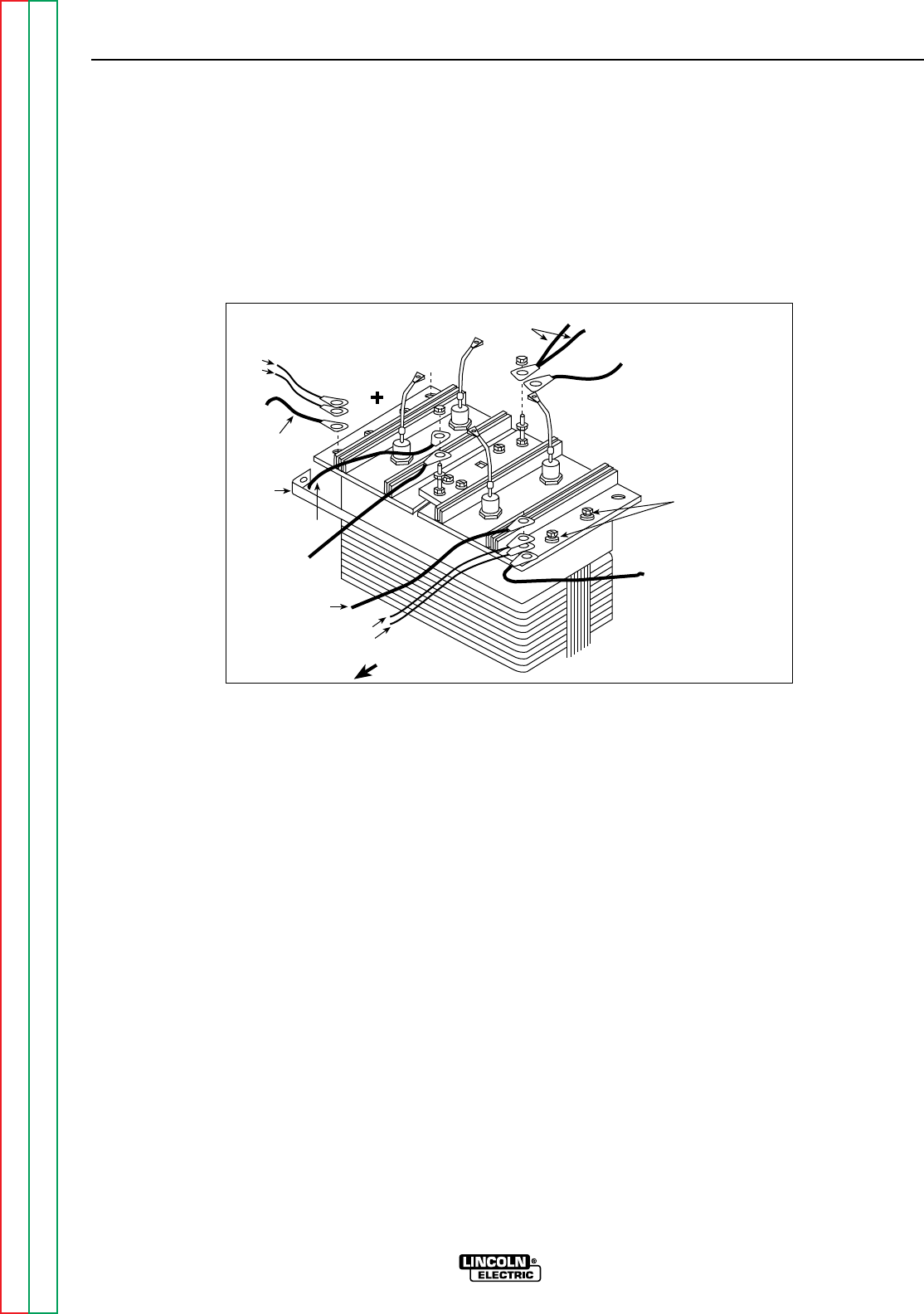
Return to Section TOC Return to Section TOC Return to Section TOC Return to Section TOC
Return to Master TOC Return to Master TOC Return to Master TOC Return to Master TOC
TROUBLESHOOTING & REPAIR
F-56 F-56
RANGER 9 RANGER 9
OUTPUT RECTIFIER BRIDGE REMOVAL
AND REPLACEMENT (continued)
FIGURE F.13 - OUTPUT RECTIFIER CONNECTIONS
Mounting Screws
with Insulators
Machine Front
#236
#236A
To Polarity Switch
Choke
Lead
S2
#235
#242
To S2 Range Sw.
W1
To Range Switch To capacitor bank
To polarity switch
PROCEDURE
1. Remove the engine spark plug wires.
2. With the 5/16” nut driver, remove the 6 sheet
metal screws from the case top.
3. Remove the rubber gasket (cover seal) from
the lift bale.
4. Remove the fuel cap. The rubber gasket for
the fill tube will come off with the case top.
5. Remove the case top, then reinstall the fuel
cap.
6. With the 5/16” nut driver, remove the 5
screws holding the right case side.
7. Remove the right case side by lifting up and
out.
For the remaining steps, refer to Figure F.13.
8. With the 1/2” wrench, remove the choke
lead, heavy lead from the S2 range switch,
leads #235 and #242 from the rectifier pos-
itive heat sink.
9. With the 1/2” wrench, remove the two heavy
leads and leads #236 and #236A from the
rectifier negative heat sink.
10. With the 1/2” wrench, remove the W1 lead
and the heavy lead going to the S1 Polarity
switch. Note lead and washer placement.
11. With the 1/2” wrench, remove the S2 lead
and the heavy lead going to the S2 Range
switch. Note lead and washer placement.

Return to Section TOC Return to Section TOC Return to Section TOC Return to Section TOC
Return to Master TOC Return to Master TOC Return to Master TOC Return to Master TOC
TROUBLESHOOTING & REPAIR
F-57 F-57
RANGER 9 RANGER 9
OUTPUT RECTIFIER BRIDGE REMOVAL
AND REPLACEMENT (continued)
12. With the 3/8” wrench and slot head screw
driver, remove the four mounting screws
(two on each side). Note the placement of
the nylon insulators. These must be in
place when you reinstall the rectifier
bridge assembly in order to electrically
insulate the bridge from the choke lam-
ination assembly.
13. Remove the rectifier assembly by tilting it
up and lifting it toward the front of the
machine.
14. Reassembly: Refer to the Wiring Diagram
for proper connections to the positive and
negative sides of the rectifier assembly.
The two sides of the bridge are marked +
and -, respectively.
NOTE: Use Dow Corning 340 on all aluminum
electrical connection surfaces.
15. WIth the 3/8” wrench and slot head screw
driver, install the four mounting screws
(two on each side). Note the placement of
the nylon insulators. These must be in
place when you install the rectifier
bridge assembly in order to electrically
insulate the bridge from the choke lam-
ination assembly.
16. With the 1/2” wrench, install the S2 lead
and the heavy lead going to the Range
switch. Note the order of fasteners and
leads.
17. With the 1/2” wrench, install the W1 lead
and the heavy lead going to the Polarity
switch. Note the order of fasteners and
leads.
18. With the 1/2” wrench, install the two heavy
leads and leads #236 and #236A to the
rectifier negative heat sink. Note the order
of fasteners: bolt and flat washer from the
bottom up through the heat sink; on top,
leads, flat washer, lock washer, and nut.
19. With the 1/2” wrench, install the choke
lead, the heavy lead, and leads #235 and
#242 to the rectifier positive heat sink.
Note the order of fasteners: bolt and flat
washer from the bottom up through the
heat sink; on top, leads, flat washer, lock
washer, and nut.
20. Reinstall the case side, fuel cap, lift bale
gasket, case top, and spark plug wire.

Return to Section TOC Return to Section TOC Return to Section TOC Return to Section TOC
Return to Master TOC Return to Master TOC Return to Master TOC Return to Master TOC
TROUBLESHOOTING & REPAIR
F-58 F-58
RANGER 9 RANGER 9
WARNING
OUTPUT CAPACITOR REMOVAL
AND REPLACEMENT
Service and repair should be performed by only Lincoln Electric factory trained personnel.
Unauthorized repairs performed on this equipment may result in danger to the technician or
machine operator and will invalidate your factory warranty. For your safety and to avoid elec-
trical shock, please observe all safety notes and precautions detailed throughout this manu-
al.
If for any reason you do not understand the test procedures or are unable to perform the
test/repairs safely, contact the Lincoln Electric Service Department for electrical trou-
bleshooting assistance before you proceed. Call 216-383-2531 or 1-800-833-9353 (WELD).
DESCRIPTION
The following procedure will aid the technician in removing the output capacitor bank of four
capacitors for maintenance or replacement.
MATERIALS NEEDED
Volt/Ohmmeter
25-watt resistor
5/16” Nut driver
1/4” Nut driver
Phillips head screw driver
Wiring Diagram
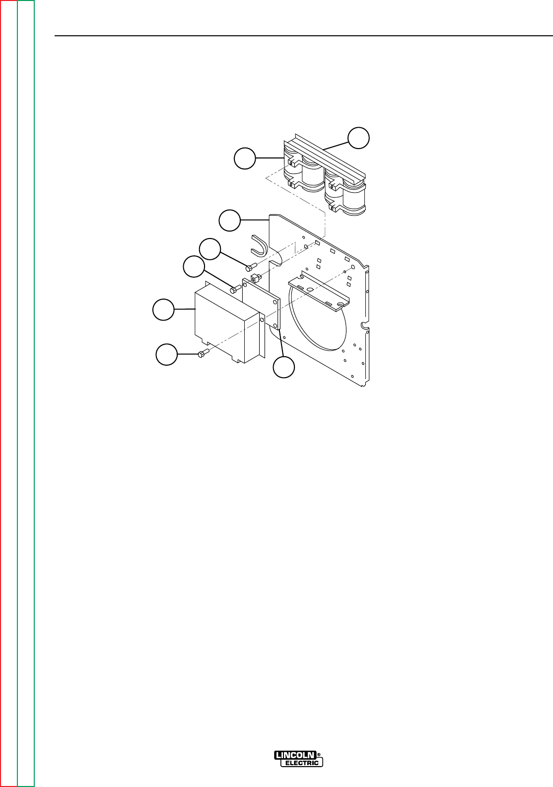
TROUBLESHOOTING & REPAIR
F-59 F-59
RANGER 9 RANGER 9
Return to Section TOC Return to Section TOC Return to Section TOC Return to Section TOC
Return to Master TOC Return to Master TOC Return to Master TOC Return to Master TOC
OUTPUT CAPACITOR REMOVAL
AND REPLACEMENT (continued)
FIGURE F.14 - OUTPUT CAPACITOR BANK/PRINTED CIRCUIT BOARD LOCATION
7
6
5
4
3
1
28
PROCEDURE
Before starting the following procedure, refer to
the topic “PC Board Troubleshooting Proce-
dures” at the beginning of this section.
1. With the 5/16” nut driver, remove the 6 sheet
metal screws from the case top.
2. Remove the rubber gasket (cover seal) from
the lift bail.
3. Remove the fuel cap. The rubber gasket for
the fill tube will come off with the case top.
4. Remove the case top, then reinstall the fuel
cap.
5. With the 5/16” nut driver, remove the five
screws holding the right case side.
6. Remove the right case side by lifting up and
out.
7. Remove the engine spark plug wires.
8. With the 5/16” nut driver, remove the printed
circuit board cover. See Figure F.14.
1. PC BOARD COVER
2. PC BOARD COVER MOUNTING
SCREW (2)
3. PC BOARD MOUNTING SCREW (5)
4. CAPACITOR BANK MOUNTING
SCREW (4)
5. VERTICAL BAFFLE
6. CAPACITOR (4)
7. BUSS BAR (2)
8. PC BOARD

Return to Section TOC Return to Section TOC Return to Section TOC Return to Section TOC
Return to Master TOC Return to Master TOC Return to Master TOC Return to Master TOC
TROUBLESHOOTING & REPAIR
F-60 F-60
RANGER 9 RANGER 9
OUTPUT CAPACITOR REMOVAL
AND REPLACEMENT (continued)
Be sure to follow the recommended static-free
methods for handling printed circuit boards.
Failure to do so can result in permanent damage
to the equipment.
9. With the 1/4” nut driver, remove the five
screws holding the printed circuit board.
10. Carefully pull the printed circuit board aside,
supported by the leads still connected to it,
so that all the screws that mount the capac-
itor bank to the vertical baffle are accessi-
ble.
11. With the volt/ohmmeter, check the voltage
across each of the four output capacitors. If
a voltage is present, use a 25-watt resistor
to discharge each capacitor.
12. With the 1/2” wrench, remove the two nuts,
bolts, and associated washers holding the
two heavy leads to the positive and negative
capacitor buss bars.
13. With the phillips head screw driver, remove
the four mounting screws holding the
capacitor bank assembly to the vertical baf-
fle.
14. Carefully remove the capacitor bank assem-
bly.
15. To replace the capacitor bank assembly,
mount the assembly to the vertical baffle
with four phillips head screws.
16. With the 1/2” wrench, attach the two heavy
leads and associated fasteners to the posi-
tive and negative buss bars. Observe
capacitor polarity.
17. With the 1/4” nut driver, mount the printed
circuit board to the vertical baffle (five
screws).
18. With the 5/16” nut driver, install the printed
circuit board cover.
19. Reinstall the case side, fuel cap, lift bail gas-
ket, and case top.
CAUTION

Return to Section TOC Return to Section TOC Return to Section TOC Return to Section TOC
Return to Master TOC Return to Master TOC Return to Master TOC Return to Master TOC
TROUBLESHOOTING & REPAIR
F-61 F-61
RANGER 9 RANGER 9
WARNING
OUTPUT CONTACTOR REMOVAL
AND REPLACEMENT
Service and repair should be performed by only Lincoln Electric factory trained personnel.
Unauthorized repairs performed on this equipment may result in danger to the technician or
machine operator and will invalidate your factory warranty. For your safety and to avoid elec-
trical shock, please observe all safety notes and precautions detailed throughout this manu-
al.
If for any reason you do not understand the test procedures or are unable to perform the
test/repairs safely, contact the Lincoln Electric Service Department for electrical trou-
bleshooting assistance before you proceed. Call 216-383-2531 or 1-800-833-9353 (WELD).
DESCRIPTION
The following procedure will aid the technician in removing the output contactor for mainte-
nance or replacement.
MATERIALS NEEDED
5/16” Nut driver
Needle nose pliers
1/2” Wrench
3/8” Wrench
Slot head screw driver
Wiring Diagram
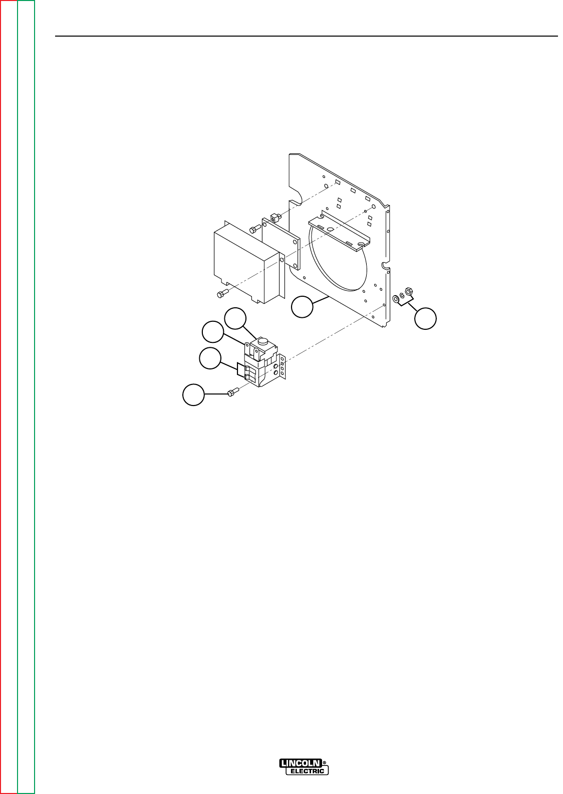
Return to Section TOC Return to Section TOC Return to Section TOC Return to Section TOC
Return to Master TOC Return to Master TOC Return to Master TOC Return to Master TOC
TROUBLESHOOTING & REPAIR
F-62 F-62
RANGER 9 RANGER 9
OUTPUT CONTACTOR REMOVAL
AND REPLACEMENT (continued)
FIGURE F.15 – OUTPUT CONTACTOR LOCATION
4
2
3154
PROCEDURE
1. With the 5/16” nut driver, remove the 6 sheet
metal screws from the case top.
2. Remove the rubber gasket (cover seal) from
the lift bail.
3. Remove the fuel cap. The rubber gasket for
the fill tube will come off with the case top.
4. Remove the case top, then reinstall the fuel
cap.
5. With the 5/16” nut driver, remove the five
screws holding the right case side.
6. Remove the right case side by lifting up and
out.
7. Remove the engine spark plug wires.
8. With the needle nose pliers, remove all #232
and #224 leads from the contactor coil. Note
placement for reassembly.
9. With the 1/2” wrench, remove the two nuts,
bolts, and associated washers holding the
two heavy leads to the output contactor.
10. With the slot head screw driver and 3/8”
wrench, remove the three mounting screws
from the contactor. The contactor can now
be removed.
11. To reinstall the output contactor, use the
slothead screw driver and 3/8” wrench to
attach the three mounting screws that hold
the contactor to the vertical baffle.
12. With the 1/2” wrench and the two nuts,
bolts, and associated washers, attach the
two heavy leads to the output contactor.
13. With the needle nose pliers, carefully attach
all #232 and #224 leads to the contactor
coil. See the Wiring Diagram and Figure
F.16 for lead placement.
14. Reinstall the case side, fuel cap, lift bail gas-
ket, and case top.
1. CONTACTOR
2. COIL LEAD CONNECTIONS
3. HEAVY LEAD CONNECTIONS
4. MOUNTING HARDWARE (3 SETS)
5. VERTICAL BAFFLE
1/96
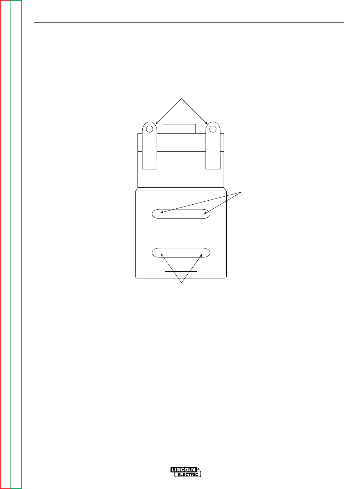
Return to Section TOC Return to Section TOC Return to Section TOC Return to Section TOC
Return to Master TOC Return to Master TOC Return to Master TOC Return to Master TOC
TROUBLESHOOTING & REPAIRs
F-63 F-63
RANGER 9 RANGER 9
OUTPUT CONTACTOR REMOVAL
AND REPLACEMENT (continued)
FIGURE F.16 – CONTACTOR COIL LEAD PLACEMENT
Leads #224
Heavy Lead
Connections
Leads #232
1/96

Return to Section TOC Return to Section TOC Return to Section TOC Return to Section TOC
Return to Master TOC Return to Master TOC Return to Master TOC Return to Master TOC
TROUBLESHOOTING & REPAIR
F-64 F-64
RANGER 9 RANGER 9
WARNING
ENGINE/ROTOR REMOVAL AND REPLACEMENT
Service and repair should be performed by only Lincoln Electric factory trained personnel.
Unauthorized repairs performed on this equipment may result in danger to the technician or
machine operator and will invalidate your factory warranty. For your safety and to avoid elec-
trical shock, please observe all safety notes and precautions detailed throughout this manu-
al.
If for any reason you do not understand the test procedures or are unable to perform the
test/repairs safely, contact the Lincoln Electric Service Department for electrical trou-
bleshooting assistance before you proceed. Call 216-383-2531 or 1-800-833-9353 (WELD).
DESCRIPTION
The following procedure will aid the technician in removing the engine and/or rotor for main-
tenance or replacement of either component.
MATERIALS NEEDED
Lincoln Electric Rotor Removal Kit (S20788) - FOR ROTOR REMOVAL ONLY
1/4” nut driver
5/16” nut driver
Slot head screw driver
3/8” Wrench
7/16” Wrench
1/2” Wrench
9/16” Wrench
5/8” Wrench
Locking pliers
Needle nose pliers
Diagonal cutters
Impact wrench
Torque wrench (ft lbs)
Feeler gauge (.017)
INSTRUCTIONS
For Engine and Rotor removal only, follow steps 1-25 under ENGINE AND ROTOR REMOVAL
PROCEDURE. For reassembly of engine and rotor go to REASSEMBLY PROCEDURE.
For rotor removal, follow the ENGINE AND ROTOR REMOVAL PROCEDURE and ROTOR
REMOVAL PROCEDURE.
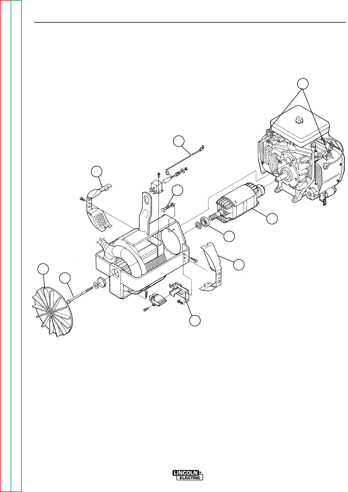
Return to Section TOC Return to Section TOC Return to Section TOC Return to Section TOC
Return to Master TOC Return to Master TOC Return to Master TOC Return to Master TOC
TROUBLESHOOTING & REPAIR
F-65 F-65
RANGER 9 RANGER 9
ENGINE/ROTOR REMOVAL AND
REPLACEMENT (continued)
FIGURE F.17 – COMPONENT LOCATIONS, ENGINE/ROTOR REMOVAL
5
3
6
1
9
2
4
1
8
7
1. STATOR COWLING COVER
2. BLOWER FAN
3. IDLE LINKAGE
4. BRUSH HOLDER BRACKET
5. ENGINE LIFT BAILS
6. STATOR/ENGINE MOUNTING BOLT
7. ROTOR
8. ROTOR SHAFT BEARING
9. ROTOR THRU-BOLT

Return to Section TOC Return to Section TOC Return to Section TOC Return to Section TOC
Return to Master TOC Return to Master TOC Return to Master TOC Return to Master TOC
TROUBLESHOOTING & REPAIR
F-66 F-66
RANGER 9 RANGER 9
ENGINE/ROTOR REMOVAL
AND REPLACEMENT (continued)
ENGINE AND ROTOR
REMOVAL PROCEDURE
1. Refer to Figure F.17 for component loca-
tions.
2. Remove the engine spark plug wires.
3. With the 5/16” nut driver, remove the 6
sheet metal screws from the case top.
4. Remove the rubber gasket (cover seal)
from the lift bale.
5. Remove the fuel cap. The rubber gasket
for the fill tube will come off with the case
top.
6. Remove the case top, the reinstall the fuel
cap.
7. WIth the 5/16” nut driver, remove the 5
screws holding the right case side and the
5 screws holding the left case side.
8. Remove the case sides by lifting up and
out.
9. WIth the 3/8” wrench, remove the battery
cover.
10. Disconnect the negative battery cable,
then the positive battery cable. BE SURE
TO DISCONNECT THE NEGATIVE BAT-
TERY CABLE FIRST. Remove the battery
and set it aside.
11. With the diagonal cutters, cut the cable
ties around the leads from the starter sole-
noid and disconnect the leads.
12. Disconnect the large black plug in front of
the fuel tank spout.
13. With the 3/8” wrench, remove the cowling
covers at the rear on the stator, both sides
of the machine.
14. WIth the 3/8” wrench, remove the two
screws that hold the vertical fan baffle in
place. Slide the baffle forward toward the
rectifier bridge heat sink assembly.
15. Hold the rotor shaft with locking pliers and
unscrew the blower fan. Turn the fan
counterclockwise. You do not need to
remove the fan from the machine, but be
sure it is completely unscrewed from the
rotor shaft.
15. With the 5/16” nut driver, disconnect the
engine choke cable from the engine. Mark
the location of the retainer for reassembly.
The other end can remain connected.
16. Disconnect the idle linkage by unsnapping
the plastic clip at the engine end of the
idler rod. Snap the clip back onto the rod
to avoid losing it; remove the rod for
reassembly.
17. Disconnect the fuel line from the fuel tank.
Plug the hose and also plug the connec-
tion at the fuel tank to prevent the escape
of gasoline fumes.
18. With the 9/16” wrenches, remove the
ground lead from the right engine foot
mounting bolt.
19. With the 7/16” wrench, remove the brush
holder bracket and leads #219 and #200A
from the stator frame.
20. With the 1/2” wrench, remove the muffler
suport bolt.
21. Support the engine with a chain hoist. Lift
bales are provided on the top of the engine
for this purpose.
22. With the 9/16” wrench, remove the right
and left engine foot mounting bolts.
23. With the 9/16” wrench, remove the four
bolts that hold the stator to the engine.
There is one lock washer per bolt.
24. With the chain hoist, unweight the engine
gently. Use a pry bar to carefully pry
between the engine and the stator frame in
order to unseat the bearing on the end of
the rotor shaft. Separate the engine and
rotor from the stator frame, supporting the
rotor by hand to prevent damage to the
rotor core.
25. Move the engine and rotor assembly to a
bench. The engine is off balance with the
rotor still attached; therefore, support the
end of the rotor with a wooden two-by-
four before unhooking the chain hoist.
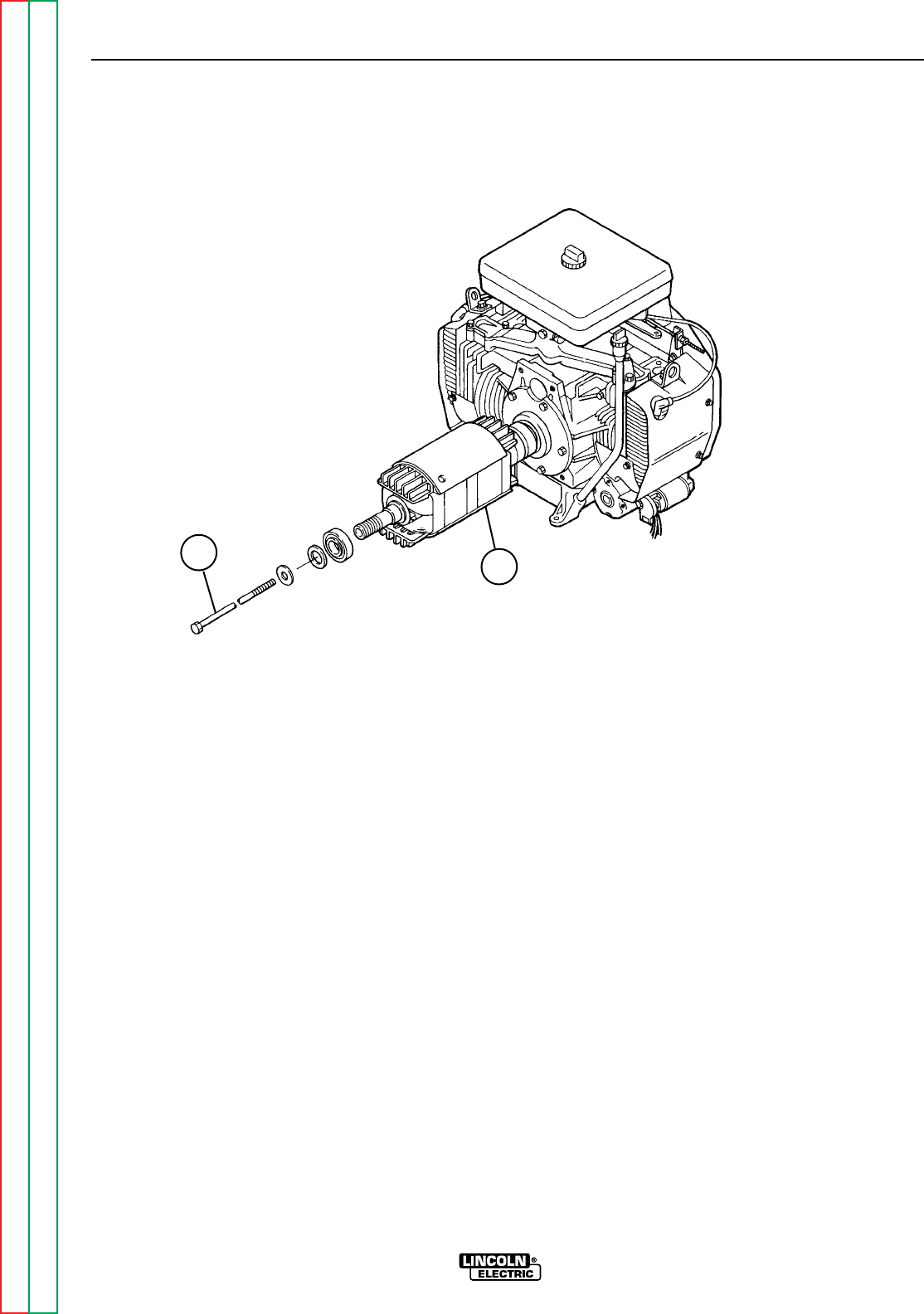
Return to Section TOC Return to Section TOC Return to Section TOC Return to Section TOC
Return to Master TOC Return to Master TOC Return to Master TOC Return to Master TOC
TROUBLESHOOTING & REPAIR
F-67 F-67
RANGER 9 RANGER 9
ROTOR REMOVAL PROCEDURE
1. To remove the rotor, double check that the
engine spark plug wires are disconnect-
ed. You will be turning the rotor during this
procedure, and this could accidentally cause
engine kickback.
2. With an impact wrench, remove the rotor
thru-bolt. See Figure F.18. If an impact
wrench is not available, use the 5/8” box
wrench. Hold the rotor with one hand and
shock the wrench with the mallet to loosen
the thru-bolt. The thru-bolt has a star wash-
er and lock washer, beveled to conform to
the rotor shaft. Pull out the thru-bolt.
3. Install the appropriate long thru-bolt (two are
provided) supplied with Lincoln Electric
Rotor Removal Kit S20788. The slot head
must face out. Screw in the bolt with the slot
head screw driver until the bolt bottoms out
on the engine crankshaft, about 3/4”.
4. Turning it counterclockwise, screw in the
left-hand thread rotor removal tool from the
kit into the rotor shaft. Support the rotor with
one hand and tighten the tool to approxi-
mately 50 ft lbs with the torque or impact
wrench.
5. If the rotor does not pop off, tighten the rotor
removal tool an additional 5 ft lbs. Hold the
rotor with one hand until the rotor pops off
the engine crankshaft.
HINT: If the rotor does not pop off, hit the end of
the rotor removal tool with a hammer.
6. Slide the rotor the rest of the way off the
crankshaft. Be careful not to lose the wash-
er that fits between the blower fan and the
rotor.
ENGINE/ROTOR REMOVAL AND
REPLACEMENT (continued)
FIGURE F.18 - ENGINE AND ROTOR REMOVED FROM STATOR
12
1. THRU-BOLT
2. ROTOR

Return to Section TOC Return to Section TOC Return to Section TOC Return to Section TOC
Return to Master TOC Return to Master TOC Return to Master TOC Return to Master TOC
TROUBLESHOOTING & REPAIR
F-68 F-68
RANGER 9 RANGER 9
REASSEMBLY PROCEDURE
NOTE: Lincoln Electric recommends that a new
bearing (Lincoln part #M9300-85) be installed
when you replace the rotor and blower assem-
bly.
1. Clean the tapered engine crankshaft. Slide
the rotor onto the shaft.
2. Insert the rotor thru-bolt, and with the
torque wrench tighten the bolt to 50 ft lbs.
3. Support the engine/rotor assembly with the
chain hoist. Fit the rotor into the stator
frame, being careful not to damage the
rotor core against the stator. The bearing
will seat into its race about half way.
4. Insert the four bolts and lock washers that
hold the engine to the stator. With the
9/16” wrench, draw the bolts up evenly in
order to seat the bearing properly. Tighten
to 22 ft-lb. moving diagonally from bolt to
bolt.
5. Check the rotor-stator air gap with the .017
feeler gauge. The measurement is taken at
the blower end of the rotor before the fan is
reinstalled. Turn the rotor with a pair of
locking pliers as necessary so that the rotor
“iron” is up to take the measurement. (The
rotor has two flat sides, which are not mea-
sured for air gap.) Slide in the gauge. Then
rotate the shaft 180 degrees and measure
again. If the gauge does not clear, loosen
the four engine/stator bolts; retighten the
bolts and recheck the air gap. Repeat until
the proper .017 minimum air gap is
achieved.
6. Fasten the ground lead to the right engine
mounting bolt and install both bolts.
7. Install the brush holder bracket back into
the stator frame. Refer to the topic “Brush
Removal and Replacement” in this section
of the manual.
8. Unplug the fuel tank connection and fuel
hose and connect them.
9. Connect the idle linkage to the idler rod.
Snap the plastic clip back into place.
10. Connect the engine choke cable at the
position marked during disassembly.
11. Screw the blower fan back onto the end of
the rotor shaft. Be sure the washer is in
place and hand tighten the fan only.
12. Reposition the vertical fan baffle and secure
it with the two screws.
13. Install the muffler support hardware.
14. Install the two cowling covers at the rear of
the stator.
15. Connect the black plug in front of the fuel
tank fill spout.
16. Connect the leads to the starter solenoid
and replace any cable ties cut during disas-
sembly.
17. Install the battery. Connect the positive
battery cable, then the negative battery
cable. BE SURE TO CONNECT THE POS-
ITIVE BATTERY CABLE FIRST.
18. Replace the battery cover.
19. Reinstall the case sides, fuel cap, lift bale
gasket, and case top. Connect the spark
plug wires.
20. Conduct the “Retest after Repair” proce-
dure, the following topic in this section of
the manual.
ENGINE/ROTOR REMOVAL AND
REPLACEMENT (KIT S20788) (continued)

Return to Section TOC Return to Section TOC Return to Section TOC Return to Section TOC
Return to Master TOC Return to Master TOC Return to Master TOC Return to Master TOC
TROUBLESHOOTING & REPAIR
F-69 F-69
RANGER 9 RANGER 9
RETEST AFTER REPAIR
Retest a machine:
• If it is rejected under test for any reason that requires you to remove any mechanical part which could affect the
machine’s electrical characteristics. OR
• If you repair or replace any electrical components.
ENGINE OUTPUT
Mode No Load RPM Load RPM
Low Idle 2150-2250 NA
High Idle 3700-3750 3100-3650
WELDER DC OUTPUT1
Output Control Range Switch Open Circuit Load Volts Load Amps
Volts
Maximum Maximum 65 - 75 25 - 35 245 - 255
WELDER AC OUTPUT1
Output Control Range Switch Open Circuit Load Volts Load Amps
Volts
Maximum Maximum 73 - 80 25 - 35 250 - 260
WELDER CV OUTPUT1
Output Control Range Switch Open Circuit Load Volts Load Amps
Volts
Maximum Wire Feed CV High 50 - 54 25 - 35 250 - 260
Maximum Wire Feed CV Med 35 - 38 20 - 24 200 - 240
Maximum Wire Feed CV Low 34 - 38 16 - 19 155 - 190
AUXILIARY POWER RECEPTACLE OUTPUT1
230 Volt Receptacle 115 Volt Receptacle2
Open Circuit Load Volts Load Amps Open Circuit Load Volts Load Amps
Voltage Voltage
236 - 255 207 - 245 39 - 43 118 - 127.5 103 - 122 78 - 83
AMPHENOL AUXILIARY OUTPUT1
42 Volt Auxiliary 115 Volt Receptacle2
Open Circuit Load Volts Open Circuit Load Volts
Voltage Voltage
43 - 50 40 - 48 115 - 126 110 - 126
FIELD AMPS AND VOLTS
Slip Ring Volts Field Amps
40 - 50 VDC 5.2 - 5.8 Amps DC
1 OUTPUT CONTROL switch set at MAXIMUM (position 10).
2 Output values of each receptacle can vary within the range shown but must be within 2 volts of each other.

Section G-1 Section G-1
RANGER 9 RANGER 9
Diagrams Section............................................................................................................Section G
Wiring Diagram RANGER 9 Onan (Code 9975)....................................................................G-2
Wiring Diagram RANGER 9 Onan CSA (Code 9976)............................................................G-3
Control PC Board (L9062) Schematic...................................................................................G-4
RF Bypass PC Board (M16675) Schematic..........................................................................G-5
Dimension Print.....................................................................................................................G-6
Control PC Board (L9062) Layout.........................................................................................G-7
Control PC Board (L9062) Components...............................................................................G-8
RF-Bypass PC Board (M16675) Layout................................................................................G-9
RF-Bypass PC Board (M16675) Components....................................................................G-10
TABLE OF CONTENTS
DIAGRAMS SECTION
Return to Master TOC Return to Master TOC Return to Master TOC Return to Master TOC
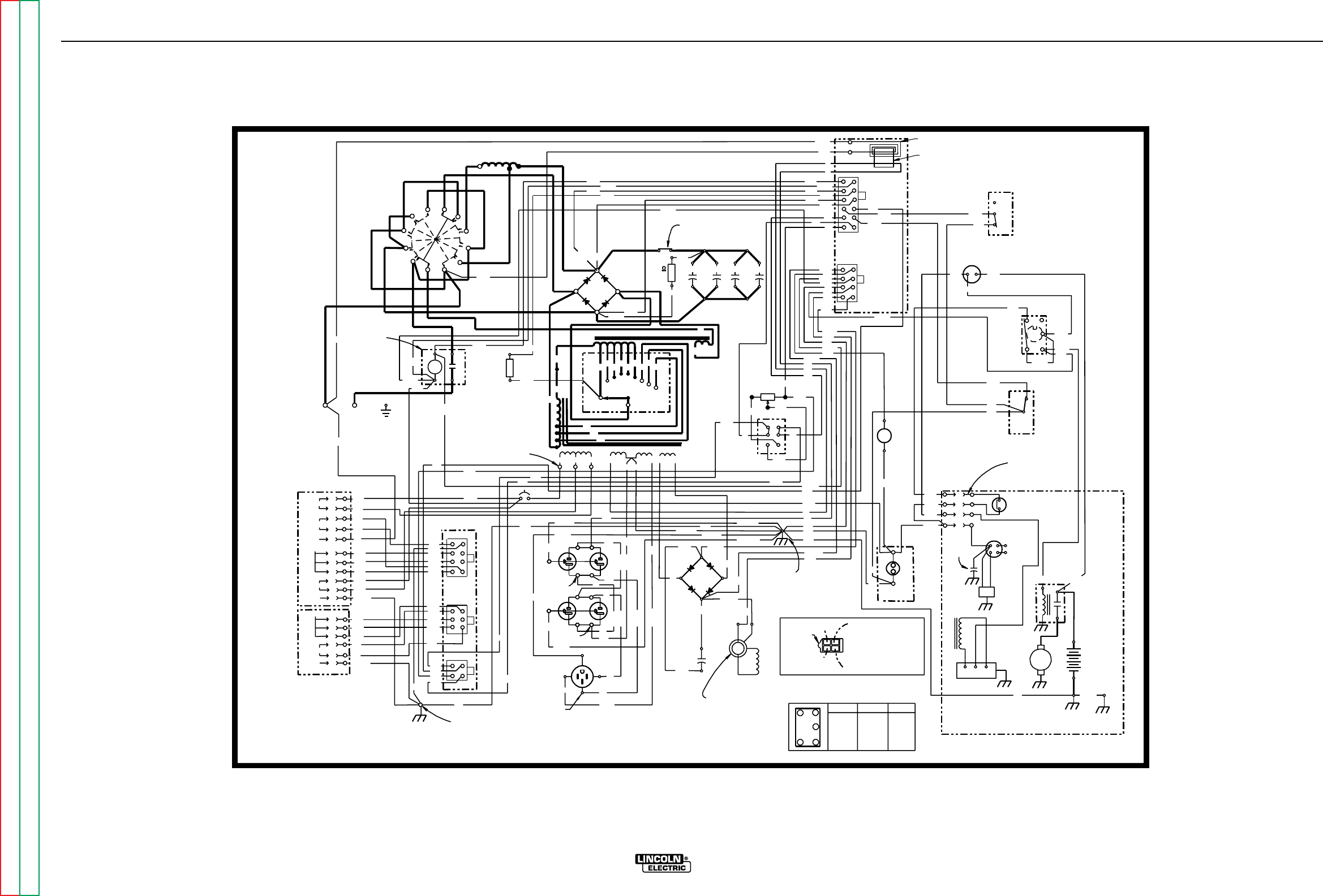
DIAGRAMS
G-2 G-2
RANGER 9 RANGER 9
236
ELECTRODE
WORK
241
GND
(+)
D1
(-)
R1
C2
25W
100 C3 C4 C5
224E
AMMETER
209
AM 1
AUTO
HIGH
3
5
6
212
CAPACITOR
ACAC B+
208
}
STARTER
REGULATOR
(+)
(-)
200A
219
200
SR
(+)
(-)
ROTOR FIELD
(+)
(-)
(+)
(-)
C1
800 MFD
CV-
CV+
DC+
DC-
AC
212 (CAVITY #1)
208 (CAVITY #3)
+-
+
-
D2
(-)
(+)
CR1
209
AC
AC
LOCATING
31 32
42 97
PC
BOARD
PCB1
1
612
1
J1
J2
4
5
8
CURRENT
SENSOR
75A
AMPHENOL 2
1
4
5
8
1
1
3
4
6
2
3
4
J3
J4
J5
31B
42
32
21
5E
GROUND SCREW
PCB2
BYPASS PC
76
10K POT
R3
75A
CW
MAX
ENGINE
HOUR METER
115 V
5K
115 V
J6
J7
9
201A
200B
SHOWN IN
POSITION
+
-
IDLER
SOLENOID
12V
CONTACTOR
AND
219
3 TURNS
232
254A
235
21
2C 75A
5E
3
76A
77A
31A
6
3A
5
5L
5L
3B
WHITE
WHITE
WHITE
BLACK
BLACK
BLACK
GREEN
BLACK
6
3B
5K
77A
76A
5E
7
3
3
5A
5F
3
76D
77D
76D
76A
77A
224
200B
224C
5A
219
224E
76
224D
208A
254A
254
3
3
77
235
242
236
232
216A
224A
224B
5F
240
75
200B
232A
216
201A
214
75
3
77
214
201A
216
219
232A
5A
224C
77
2C
2A
4A
77C
76C
75C
2B
75B
77B
76B
4B
4B
2B
75B
76B
77B
75C
76C
77C
2A
4A
(J)
(A)
(D)
(C)
(H)
(E)
(F)
(G)
(I)
(K)
(B)
(A)
(B)
(C)
(D)
(E)
(F)
GND-C
GND-G
115VAC
CONTACTOR
WORK
REMOTE CONTROL
42VAC
GROUND
REMOTE CONTROL
CONTACTOR
GROUND GND-B
GND-A
77A
76A
4C
4C
250
50W
R2
242 S6
L2
CB1
SOLENOID
208B
216A
S3
41
2
36
STOP RUN START
1 & 2 4 & 6 3 & 2
CLOSED CLOSED CLOSED
S3 SWITCH LOGIC
(MOMENTARY)
S4
STOP
RUN
START
212
250
1
3
2
4
7
2C
2C
240
224A&B (CAVITY #4)
232
254
247
C1
W1
W2
C2
C3
R1 R2R3R4 R5 R6 C1C2C3
S2
REACTOR E
S1
STATOR
SHOWN IN
"HIGH'
POSITION
5C
5B
208
5C
5D
31A
224B (CAVITY #2)
232A
200B
GND-G
232A
"ALWAYS ON"
247
216
208A
5B
5D
201
201
BETWEEN AMPHENOL HOLES
ON
5
224C
224E
224
236A
236A
245
CLEVELAND, OHIO U.S.A.
12-16-93A
L9112
STARTER
MOTOR
NOTES:
31,000 MFD
CAPACITORS
SLIP
RINGS WELDER LEAD END
(NOTE CAVITY NUMBERS)
REMOTE SWITCH
(SHOWN IN
REMOTE POSITION)
IN LINE CONNECTORS
(3 PLACES)
S1
ELECTRODE POLARITY
SWITCH
OUTPUT
CONTACTOR
L1
(CHOKE)
OUTPUT
RECTIFIER
S5
IDLER
SWITCH
AMPHENOL 1
125/250V. SINGLE
RECEPTACLE
GROUND SCREW
BLOWER BAFFLE
OUTPUT
RHEOSTAT
OIL PRESSURE
SWITCH
TO SPARK
PLUGS
SLIP RING
NEAREST LAMINATION
FLYWHEEL
ALTERNATOR
ENGINE
FOOT ENGINE
CROSS
SUPPORT
GND-H
B-
WELDING TERMINAL
CONTROL SWITCH
25 OHM
240
GND-E
242
GREEN
GND-D
GND-C
GND-E
GND-D
GREEN
VOLTAGE
IGNITION
COIL
IGNITION
MODULE
DIAGRAM "A"
ENGINE TERMINAL
BLOCK CONNECTION
SEE DIAGRAM "A" FOR
ENGINE TERMINAL
BLOCK CONNECTION.
IDLER
S2A (CLOSED
WITH S2 IN
C1, C2 OR C3
POSITION)
RANGE
SWITCH
S2
(10AMP)
TAB
COLORED
SILVER
TERMINALS
COLORED
SILVER
TERMINALS
COLORED
SILVER
TERMINALS
RANGER 9 (ONAN)
ELECTRICAL SYMBOLS PER E1537
ALL CASE FRONT COMPONENTS VIEWED FROM REAR.
NOTE: This diagram is for reference only. It may not be accurate for all machines covered by this manual. The
specific diagram for a particular code is pasted inside the machine on one of the enclosure panels.
WIRING DIAGRAM RANGER 9 ONAN (CODE 9975)
Return to Section TOC Return to Section TOC Return to Section TOC Return to Section TOC
Return to Master TOC Return to Master TOC Return to Master TOC Return to Master TOC
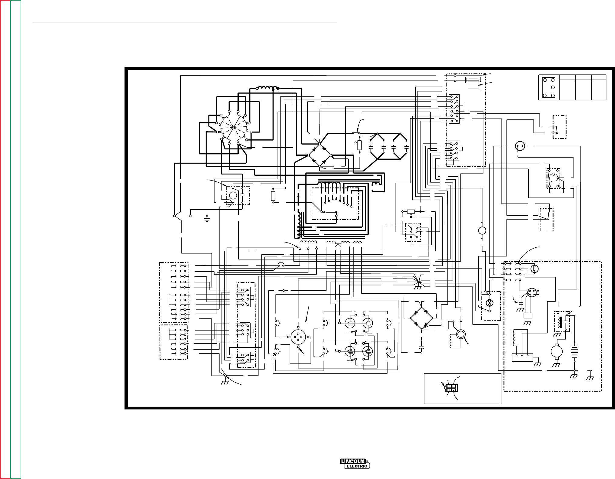
DIAGRAMS
G-3 G-3
236
ELECTRODE
WORK
241
GND
(+)
D1
(-)
R1
C2
25W
100 C3 C4 C5
224E
AMMETER
209
AM 1
AUTO
HIGH
3
5
6
212
CAPACITOR
ACAC B+
208
}
STARTER
REGULATOR
(+)
(-)
CV-
CV+
DC+
DC-
AC
212 (CAVITY #1)
208 (CAVITY #3)
+-
+
-
CR1
209
LOCATING
31 32
42 97
PC
BOARD
PCB1
1
612
1
J1
J2
4
5
8
CURRENT
SENSOR
75A
AMPHENOL 2
1
4
5
8
1
1
3
4
6
2
3
4
J3
J4
J5
31B
42
32
21
5E
GROUND SCREW
PCB2
BYPASS PC
76
10K POT
R3
75A
CW
MAX
ENGINE
HOUR METER
SHOWN IN
POSITION
+
-
IDLER
SOLENOID
12V
CONTACTOR
AND
219
3 TURNS
232
254A
235
21
2C 75A
76A
77A
31A
77A
76A
3
3
5A
5F
3
76D
77D
76D
76A
77A
224
200B
224C
5A
219
224E
76
224D
208A
254A
254
3
3
77
235
242
236
232
216A
224A
224B
5F
240
75
200B
232A
216
201A
214
75
3
77
214
201A
216
219
232A
5A
224C
77
2C
2A
4A
77C
76C
75C
2B
75B
77B
76B
4B
4B
2B
75B
76B
77B
75C
76C
77C
2A
4A
115VAC
CONTACTOR
WORK
REMOTE CONTROL
42VAC
GROUND
REMOTE CONTROL
CONTACTOR
GROUND GND-B
GND-A
4C
4C
250
50W
R2
242
S6
L2
CB1
SOLENOID
208B
216A
S3
41
2
36
STOP RUN START
1 & 2 4 & 6 3 & 2
CLOSED CLOSED CLOSED
S3 SWITCH LOGIC
(MOMENTARY)
S4
STOP
RUN
START
212
250
1
3
2
4
7
2C
2C
240
224A&B (CAVITY #4)
232
254
247
C1
W1
W2
C2
C3
R1 R2R3R4 R5 R6 C1C2C3
S2
REACTOR E
S1
STATOR
SHOWN IN
"HIGH'
POSITION
5C
5B
208
5C
5D
31A
224B (CAVITY #2)
232A
GND-D
232A
"ALWAYS ON"
247
216
208A
5B
5D
BETWEEN AMPHENOL HOLES
ON
224C
224E
224
236A
236A
245
CLEVELAND, OHIO U.S.A.
12-16-93A
L9113
STARTER
MOTOR
NOTES:
31,000 MFD
CAPACITORS
WELDER LEAD END
(NOTE CAVITY NUMBERS)
REMOTE SWITCH
(SHOWN IN
REMOTE POSITION)
S1
ELECTRODE POLARITY
SWITCH
OUTPUT
CONTACTOR
L1
(CHOKE)
OUTPUT
RECTIFIER
S5
IDLER
SWITCH
AMPHENOL 1
GROUND SCREW
BLOWER BAFFLE
OUTPUT
RHEOSTAT
OIL PRESSURE
SWITCH
TO SPARK
PLUGS
FLYWHEEL
ALTERNATOR
ENGINE
FOOT ENGINE
CROSS
SUPPORT
GND-H
B-
WELDING TERMINAL
CONTROL SWITCH
25 OHM
240
GND-E
242
GND-E
VOLTAGE
IGNITION
COIL
IGNITION
MODULE
DIAGRAM "A"
ENGINE TERMINAL
BLOCK CONNECTION
SEE DIAGRAM "A" FOR
ENGINE TERMINAL
BLOCK CONNECTION.
IDLER
S2A (CLOSED
WITH S2 IN
C1, C2 OR C3
POSITION)
RANGE
SWITCH
S2
(10AMP)
200A
200
201
(+)
(-)
ROTOR FIELD
(+) (-)
(+)
(-)
C1
800 MFD
D2
(+)
AC
AC
201
9
201A
200B
5E
7
77A
76A
8
115 V
SILVER
115/230V
15A
CB6
15A
CB4
15A
15A
CB5 CB7
J6
J8
5L
10 13
5K
5
11
5K 115 V
J7
3C
3D
GREEN
GREEN
GREEN
WHITE
BLACK
BLACK
15
GND-G
GND-C
GND-D
125/250V. SINGLE
RECEPTACLE
GND-C
GND-G 5E
IN LINE CONNECTORS
(3 PLACES)
5L
SLIP
RINGS
POSITIVE SLIP
RING NEAREST
LAMINATION
5
3E
6
50A
CB2
50A
CB3
12
3D
15
10
8
13
WHITE
WHITE
WHITE
BLACK
BLACK
3A
3B 3A 3B
3C
BLACK
BLACK
BLACK
BLACK
11
BLACK BLACK
BLACK
BLACK
BLACK
BLACK BLACK
33E
H
C
D
A
J
E
F
G
I
K
B
A
B
C
D
E
F
TERM.
COLORED SILVER
COLORED
TERMINALS
SILVER
COLORED
TERMINALS
TAB
RANGER 9 ONAN (CSA VERSION)
ELECTRICAL SYMBOLS PER E1537
ALL CASE FRONT COMPONENTS VIEWED FROM REAR.
NOTE: This diagram is for reference only. It may not be accurate for all machines covered by this manual. The
specific diagram for a particular code is pasted inside the machine on one of the enclosure panels.
WIRING DIAGRAM RANGER 9 ONAN CSA (CODE 9976)
RANGER 9 RANGER 9
Return to Section TOC Return to Section TOC Return to Section TOC Return to Section TOC
Return to Master TOC Return to Master TOC Return to Master TOC Return to Master TOC
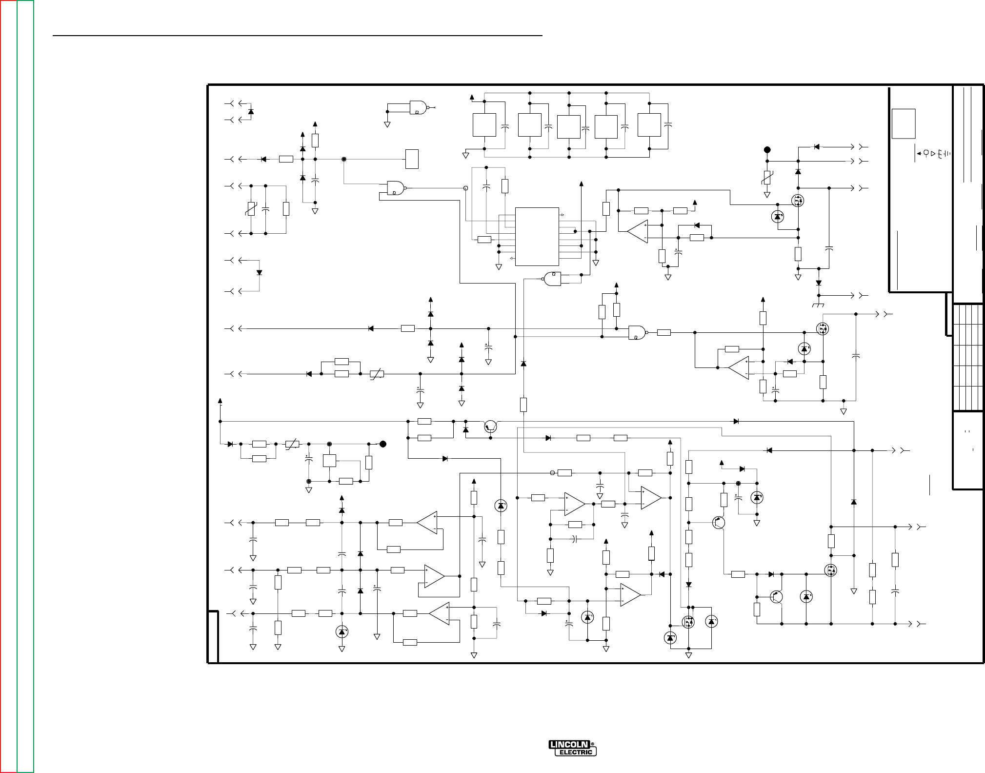
DIAGRAMS
G-4 G-4
77
9061
L
2C
475
R52
242
247
4.75K
R47
1400V
.0047
C9
5W
10V
DZ1
224E
240
236
235
250
76
232
COM
COM
+12V
COM
+10V
COM COM
COM
COM
COM
+10V
+10V
LAST CHANGE
5A
NOT SHOW THE EXACT COMPONENTS OR CIRCUITRY OF CONTROLS HAVING A COMMON CODE
WITHOUT AFFECTING THE INTERCHANGEABILITY OF A COMPLETE BOARD, THIS DIAGRAM MAY
RESISTORS = Ohms (
LAST NO. USED
42
VOLTAGE NET
1/4W
1A, 400V
(UNLESS OTHERWISE SPECIFIED)
UNLESS OTHERWISE SPECIFIED)
GENERAL INFORMATION
CAPACITORS =
232A
219
#201A
N.A. SINCE COMPONENTS OR CIRCUITRY ON A PRINTED CIRCUIT BOARD MAY CHANGE
SUPPLY
NO.
FRAME CONNECTION
LABELS
COMMON CONNECTION
D-
R-
216
39
UNLESS OTHERWISE SPECIFIED)
(
MFD
.022/50V
214
ELECTRICAL SYMBOLS PER E1537
C-
224C
94
DATE
DR.
DIODES =
EARTH GROUND CONNECTION
EQUIP.
SHT.
L
POWER SUPPLY SOURCE POINT
NONE
TYPE
SCALE
SUBJECT
3/12/93
SUP'S'D'G.
CHK.
CLEVELAND, OHIO U.S.A.
THE LINCOLN ELECTRIC CO.
9061
-FIELD
S18104-1
IRFP250
HEAT SINK
NOTES :
+FIELD
WITH PUBLISHED STANDARDS
ON HOLES SIZES PER E-2056
ON 3 PLACE DECIMALS IS + .OO2
MATERIAL TOLERANCE ("t") TO AGREE
NUMBER.
ON ALL ANGLES IS + .5 OF A DEGREE
UNLESS OTHERWISE SPECIFIED TOLERANCE
ON 2 PLACE DECIMALS IS + .O2
200B
1W
15V
DZ8
400V
.22
C21
G
D
S
33A
200V
Q4
4.75K
R81
4.75K
R82
J1
5
15A
200V
D24
5W
.5
R28
1W
15V
DZ12
600V
.05
C22
26.7K
R31
1N4936
D20
J1
2
J1
1
J1
3
G
D
S
18A
200V
Q5
J1
4
G
D
S
18A
200V
Q6
3A
600V
D18
5W
.5
R25
3A
600V
D19
600V
.05
C39
J1
6
J1
8
J1
7
1N4936
D17
COM
1/2W
5.1
R83
COM
.1
7W
R80
X1
14
13
12
+10V
+10V
COM COM
COM
COM
COM
COM
+10V
COM
+10V
COM
COM
+10V
+10V
COM
+10V
COM
COM
4536B
X3
16
8
15.0K
R62
26.7K
R61
10K
R89
1.82K
R55
10K
R54
8A
150V
Q11
SS
DECODE
4536B
V
V
8
RESET
IN 1
OUT 1
OUT 2
8 BY-PASS
CLOCK INH
B
C
D
SET
A
SC
16
DD
MONO IN
O
INH
X3
1
7
9
3
12
15
4
6
5
14
13
2
10
11
6.81K
R53
COM
1.8
20V
C38
X4
4
5
6
100V
.047
C19
13.7K
R11
C32
C33
LM2901
X2
3
12
LM224
X1
4
11
3.32K
R5
D11
C14
18
15V
C16
1N4936
D27
2K
R15
100K
R58
MAX OUT AT LOW IDLE
-B
1.00K
R56
75
R93
D38
4.75K
R57
33.2K
R10
1W
18V
DZ11
COM
+10V
COM
COM
COM
+10V
CURRENT
-B
AMP.
TP-D
1W
10V
DZ9
3.32K
R6
C13
COM
Q4 OVERCURRENT
PROTECTION
50V
0.1
C15
1W
15V
DZ4
6.81K
R79
100V
1A
Q1
1W
75V
DZ5
COM
X1
7
6
5
4093B
X4
7
14
+10V
15J
50V
TP1
-B
C29
10K
R26
-D
3.32K
R21
4.75K
R92
X5
1
3
26.7K
R22
18
15V
C23
1W
15V
DZ10
47.5K
R27
133K
R30
C30
EFFECT
47.5K
R20
HALL
Q6 OVERCURRENT PROTECTION
1N4936
D16
X2
2
4
5
GND
X4
11
12
13
+12V
133K
R19
10K
R18
C31
4.75K
R88
D2
+10V
-A
75 -D
TP-C
-C
TP-B
REMOTE INPUT
SNUBBER
TP-E
SWITCH
TO IDLER
-A
NOT USED
-C
TP-F
3.32K
R38
68.1
R35
+
REF
-
TL431
X7
1
6
8
68.1
R36
J2
2
D28
10K
R39
475
R48
100
15V
C6
+
t
56
R37
+
t
56
R90
J2
9
1N4007
D36
68.1
R86
J2
3
1N4007
D31
47.5
R41
47.5
R40
100
R3
D35
68.1
R91
1400V
.0047
C8
D8
1.8
20V
C12
475
R50
50V
0.1
C11
X1
1
2
3
4.75K
R46
47.5
R44
J2
7
4.75K
R42
475
R51
4.75K
R43
47.5
R45
J2
1
50V
0.1
C10
D7
1400V
.0047
C7
475
R49
2W
4.7K
R4
X4
10
8
9
J2
8
600V
.05
C34
J2
4
X5
X4
3
2
1
J2
6
D29
38J
130V
TP2
D32
C1
J2
11
4.75K
R2
100
R1
D42
1N5406
J2
12
J2
10
D1
J2
5
D41
5W
20
R12
D3
D37
D39
D14
D40
1.8
20V
C37
X1
8
9
10
5W
20
R13
-D
HYSTERESIS
TP-A
-A
PROTECTION
Q5 OVERCURRENT
75
R94
475
R69
10K
R66
681K
R65
50V
0.1
C17
SWITCH
FLASH
D4
10K
R63
FET DRIVER
LEVEL SHIFT
-C
1N4936
D25
1.00K
R72
52.3K
R64
1N4936
D26
X2
10
13
11
600mA
40V
Q3
6.19K
R32
18
15V
C35
X2
1
6
7
5W
20V
DZ6
332
R71
100
50V
C18
500mA
300V
Q2
5W
390
R67
1N4936
D22
3A
200V
D30
475
R68
D21
50V
820p
C2
39.2K
R60
475
R70
X2
8
14
9
+10V
+10V
26.7K
R59
I.E.B./TEN
FILE: L9061_1BB
BS
SCHEMATIC, CONTROL BOARD
RANGER 9
12-16-93A
CONTROL PC BOARD (L9062) SCHEMATIC
NOTE: Lincoln Electric assumes no responsibility for liabilities resulting from board level troubleshooting. PC Board repairs will invalidate your factory warranty. This Printed Circuit Board schematic is provided for reference
only. It may not be totally applicable to your machine’s specific PC board version. This diagram is intended to provide general information regarding PC board function. Lincoln Electric discourages board level trou-
bleshooting and repair since it may compromise the quality of the design and may result in Danger to the Machine Operator or Technician. Improper PC board repairs could result in damage to the machine.
RANGER 9 RANGER 9
Return to Section TOC Return to Section TOC Return to Section TOC Return to Section TOC
Return to Master TOC Return to Master TOC Return to Master TOC Return to Master TOC
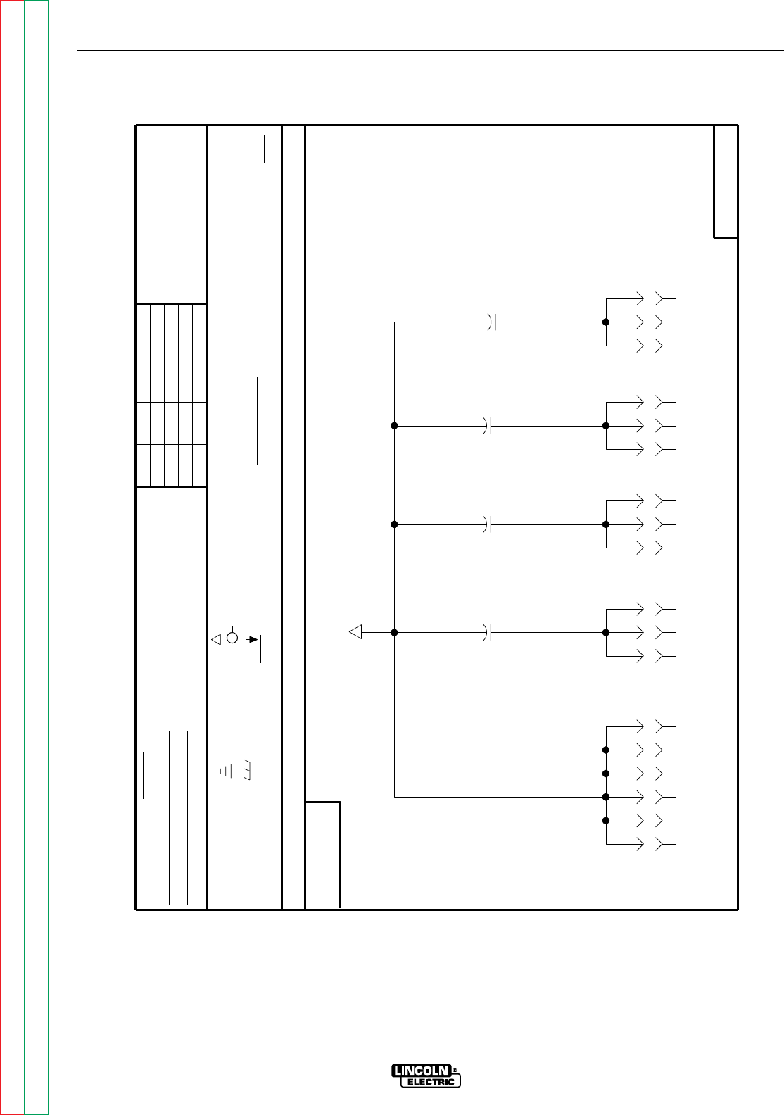
Return to Section TOC Return to Section TOC Return to Section TOC Return to Section TOC
Return to Master TOC Return to Master TOC Return to Master TOC Return to Master TOC
DIAGRAMS
G-5 G-5
RANGER 9 RANGER 9
AND IS NOT TO BE REPRODUCED, DISCLOSED OR USED WITHOUT THE EXPRESS PERMISSION OF
1400V
.0047
C4
J4
6
J5
6
J5
1
J3
3
J4
3
J5
3
J5
8
J5
7
J3
4
J4
5
1400V
.0047
C3
1400V
.0047
C2
J4
1
J3
1
J4
4
J5
2
J5
4
J3
2
J4
2
J5
5
com
8/1/91
RF BYPASS SCHEMATIC
LABELS
FRAME CONNECTION
SUPPLY
POWER SUPPLY SOURCE POINT
THIS SHEET CONTAINS PROPRIETARY INFORMATION OWNED BY
EQUIP.
TYPE
THE LINCOLN ELECTRIC CO.
UNLESS OTHERWISE SPECIFIED)
NONE
I.E.B.
THE LINCOLN ELECTRIC CO.
THE INTERCHANGEABILITY
WITHOUT AFFECTING
EARTH GROUND CONNECTION
CIRCUIT BOARD
COMMON CONNECTION
THIS DIAGRAM MAY NOT
A PRINTED
OF A COMPLETE
N.A.
MAY CHANGE
SINCE COMPONENTS OR CIRCUITRY ON
BOARD.
OR CIRCUITRY OF
NOTES :
CLEVELAND, OHIO U.S.A.
SHOW THE EXACT COMPONENTS
SUBJECT
VOLTAGE NET
CANADA
SCALE
SUP'S'D'G.DATE
DR. NO.
ON 2 PLACE DECIMALS IS + .O2
SHT.
MATERIAL TOLERANCE ("t") TO AGREE
AUSTRALIA
ON ALL ANGLES IS + .5 OF A DEGREE
WITH PUBLISHED STANDARDS
ON HOLES SIZES PER E-2056
CHK.
ON 3 PLACE DECIMALS IS + .OO2
Ch'ge.Sht.No.
FRANCE
CONTROLS HAVING A COMMON CODE NUMBER. DIODES =
ELECTRICAL SYMBOLS PER E1537
GENERAL INFORMATION
1/4W
(
UNLESS OTHERWISE SPECIFIED)
1A, 400V
RESISTORS = Ohms (
(UNLESS OTHERWISE SPECIFIED)
CAPACITORS = .022/50V
MFD
UNLESS OTHERWISE SPECIFIED TOLERANCE
THE LINCOLN ELECTRIC CO.
1400V
.0047
C1
S20272
S20272
S20272-1A
5-8-92
BS
NOTE: Lincoln Electric assumes no responsibility for liabilities resulting from board level troubleshooting. PC
Board repairs will invalidate your factory warranty. This Printed Circuit Board schematic is provided for
reference only. It may not be totally applicable to your machine’s specific PC board version. This dia-
gram is intended to provide general information regarding PC board function. Lincoln Electric discour-
ages board level troubleshooting and repair since it may compromise the quality of the design and may
result in Danger to the Machine Operator or Technician. Improper PC board repairs could result in dam-
age to the machine.
RF BYPASS PC BOARD (M16675) SCHEMATIC
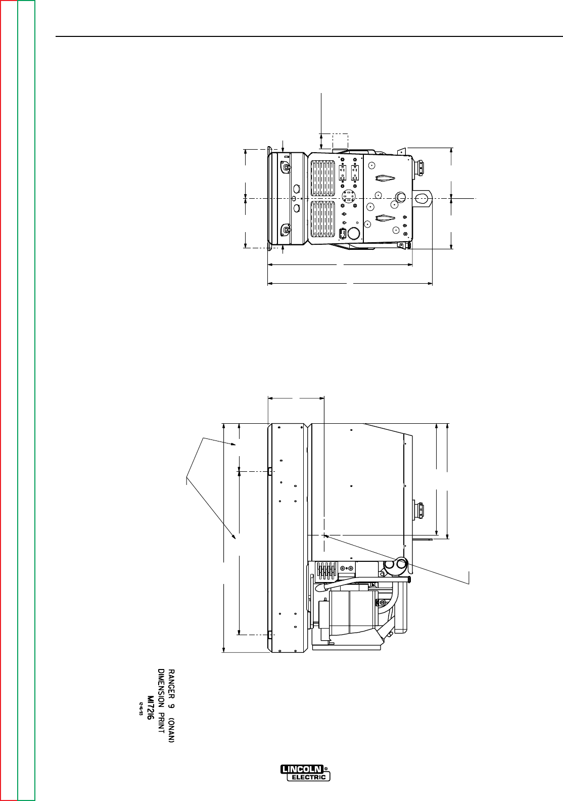
Return to Section TOC Return to Section TOC Return to Section TOC Return to Section TOC
Return to Master TOC Return to Master TOC Return to Master TOC Return to Master TOC
DIAGRAMS
G-6 G-6
RANGER 9 RANGER 9
30.00
9.31
CENTER OF GRAVITY WITH OIL IN
ENGINE AND FULL FUEL TANK.
9.29 21.21
26.59
30.28
C
20.51
LOF SHAFT
42.00
30.00
FOR OIL FILTER
REMOVAL
2.75
9.09
17.00
9.09
10.32
UNDERCARRIAGE MOUNTING HOLES
8.80
DIMENSION PRINT

Return to Section TOC Return to Section TOC Return to Section TOC Return to Section TOC
Return to Master TOC Return to Master TOC Return to Master TOC Return to Master TOC
DIAGRAMS
G-7 G-7
RANGER 9 RANGER 9
NOTE: Lincoln Electric assumes no responsibility for liabilities resulting from board level troubleshooting. PC
Board repairs will invalidate your factory warranty. This Printed Circuit Board schematic is provided for
reference only. It may not be totally applicable to your machine’s specific PC board version. This dia-
gram is intended to provide general information regarding PC board function. Lincoln Electric discour-
ages board level troubleshooting and repair since it may compromise the quality of the design and may
result in Danger to the Machine Operator or Technician. Improper PC board repairs could result in dam-
age to the machine.
CONTROL PC BOARD (L9062) LAYOUT

Return to Section TOC Return to Section TOC Return to Section TOC Return to Section TOC
Return to Master TOC Return to Master TOC Return to Master TOC Return to Master TOC
DIAGRAMS
G-8 G-8
RANGER 9 RANGER 9
NOTE: Lincoln Electric assumes no responsibility for liabilities resulting from board level troubleshooting. PC
Board repairs will invalidate your factory warranty. This Printed Circuit Board schematic is provided for
reference only. It may not be totally applicable to your machine’s specific PC board version. This dia-
gram is intended to provide general information regarding PC board function. Lincoln Electric discour-
ages board level troubleshooting and repair since it may compromise the quality of the design and may
result in Danger to the Machine Operator or Technician. Improper PC board repairs could result in dam-
age to the machine.
CONTROL PC BOARD (L9062) COMPONENTS
X7 IC-VOLT REF,ADJ,PRECISION,431I
X4 IC-VOLT REG,ADJ,3-T,(+),A
X3 IC-CMOS,TIMER,PROGRAMMABLE,4536
X1 IC-OP-AMP,QUAD,GEN-PURPOSE,224N
TP2 MOV-130VRMS,38J,14MM
TP1 MOV-50VRMS,15J,14MM
R93,R94 RESISTOR-MF,1/4W,75.0,1%
R83 RESISTOR-CC,1/2W,5.1,5%
R71 RESISTOR-MF,1/4W,332,1%
R67 RESISTOR-WW,5W,390,5%,SQ
R65 RESISTOR-MF,1/4W,681K,1%
R64 RESISTOR-MF,1/4W,52.3K,1%
R62 RESISTOR-MF,1/4W,15.0K,1%
R60 RESISTOR-MF,1/4W,39.2K,1%
R58 RESISTOR-MF,1/4W,100K,1%
R56,R72 RESISTOR-MF,1/4W,1.00K,1%
R55 RESISTOR-MF,1/4W,1.82K,1%
R53,R79 RESISTOR-MF,1/4W,6.81K,1%
R69,R70 R48,R49, RESISTOR-MF,1/4W,475,1%
R50,R51,R52,R68
R40,R41,R44,R45 RESISTOR-MF,1/4W,47.5,1%
R37,R90 THERMISTOR-PTC,56 OHMS,90MA
R35,R36,R86,R91 RESISTOR-MF,1/4W,68.1,1%
R32 RESISTOR-MF,1/4W,6.19K,1%
R22,R31,R59,R61 RESISTOR-MF,1/4W,26.7K,1%
R20,R27 RESISTOR-MF,1/4W,47.5K,1%
R19,R30 RESISTOR-MF,1/4W,133K,1%
R89 R18,R26, RESISTOR-MF,1/4W,10.0K,1%
R39,R54,R63,R66
R15 RESISTOR-MF,1/4W,2.00K,1%
R12,R13 RESISTOR-WW,5W,20,5%,SQ
R11 RESISTOR-MF,1/4W,13.7K,1%
R10 RESISTOR-MF,1/4W,33.2K,1%
R5,R6,R21,R38 RESISTOR-MF,1/4W,3.32K,1%
R4 RESISTOR-CC,2W,4.7K,10%
R82,R88,R92 R2,R42,
R43,R46,R47,R57,R81
R1,R3 RESISTOR-MF,1/4W,100,1%
Q5,Q6 TRANSISTOR-NMF,T220,18A,200V,IRF6
Q3 TRANSISTOR-P,T226,0.5A,40V,2N4403
Q2 TRANSISTOR-P,T226,0.5A,300V,MPS-A92
Q1 TRANSISTOR-NMF,4PDIP,1A,100V,RFD110
J2 CONNECTOR,MOLEX,MINI,PCB,12-PIN
J1 CONNECTOR,MOLEX,MINI,PCB,8-PIN
DZ11 ZENER DIODE-1W,18V,5%,1N4746A
DZ9 ZENER DIODE-1W,10V,5%,1N4740A
DZ6 ZENER DIODE-5W,20V,5%,1N5357B
DZ5 ZENER DIODE-1W,75V,5%,1N4761A
DZ4,DZ8,
DZ10,DZ12 ZENER DIODE-1W,15V,5%,1N4744A
DZ1 ZENER DIODE-5W,10V,5%,1N5347B
D31,D36 DIODE-AXLDS,1A,1000V
D30 DIODE-AXLDS,3A,200V,1N5402
D24 DIODE-FR,T220,14A,200V,MUR1520
D18,D19,D42 DIODE-AXLDS,3A,600V,1N5406
D16,D17,D20,D22, DIODE-AXLDS,1A,400V,FR,1N4936
D25,D26,D27
D1,D2,D3,D4,D7,D8,D11,D14 DIODE-AXLDS,1A,400V
D21,D28,D29,D32,D35,D37
D38,D39,D40,D41
C22,C34,C39 CAPACITOR-CD,.05,600V,+80/-20%
C19 CAPACITOR-PEMF,.047,100V,10%
C18 CAPACITOR-ALEL,100,50V,+75/-10%
C16,C23,C35 CAPACITOR-TAEL,18,15V,10%
C12,C37,C38 CAPACITOR-TAEL,1.8,20V,10%
C10,C11,C15,C17 CAPACITOR-CEMO,0.1,50V,10%
C7,C8,C9 CAPACITOR-CD,.0047/.005,1400V,20%
C6 CAPACITOR-ALEL,100,15/16V,+75/-10%
C2 CAPACITOR-CEMO,820P,50V,5%
C1,C13,C14,
C29,C30,C31,C32 CAPACITOR-CEMO,.022,50V,20%
C33
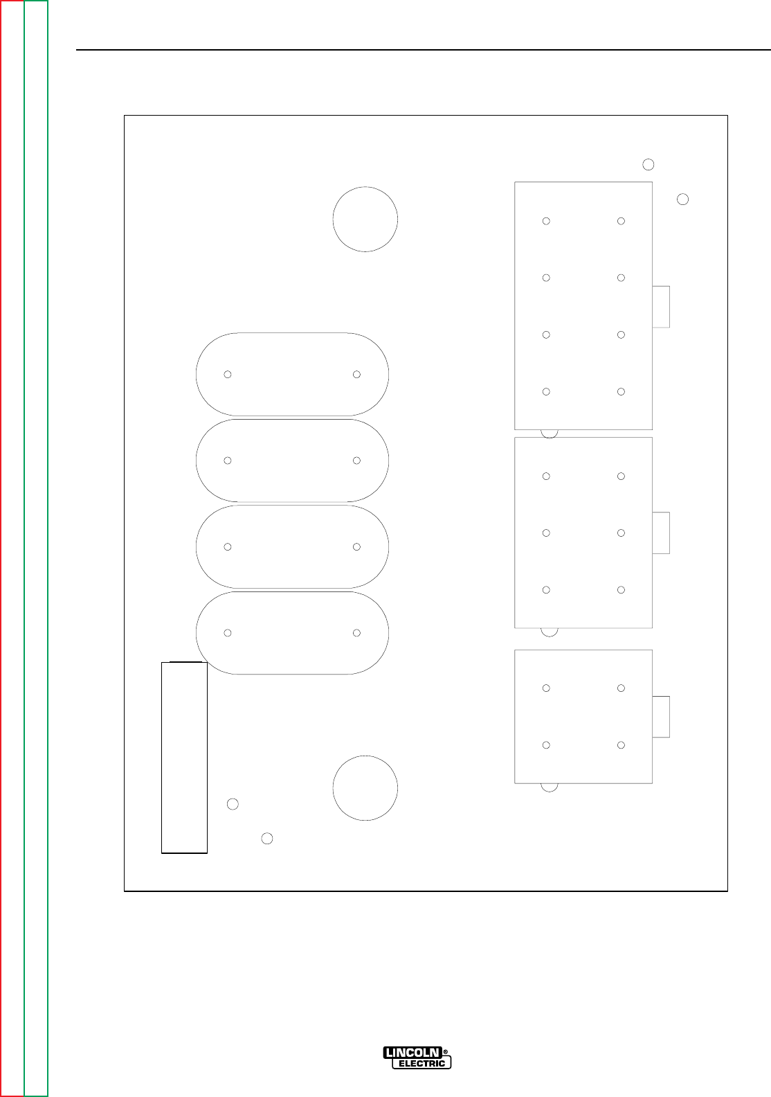
Return to Section TOC Return to Section TOC Return to Section TOC Return to Section TOC
Return to Master TOC Return to Master TOC Return to Master TOC Return to Master TOC
DIAGRAMS
G-9 G-9
RANGER 9 RANGER 9
J3 J4 J5
C1
C2
C3
C4
J3
RF BYPASS
J4 J5
M16675
NOTE: Lincoln Electric assumes no responsibility for liabilities resulting from board level troubleshooting. PC
Board repairs will invalidate your factory warranty. This Printed Circuit Board schematic is provided for
reference only. It may not be totally applicable to your machine’s specific PC board version. This dia-
gram is intended to provide general information regarding PC board function. Lincoln Electric discour-
ages board level troubleshooting and repair since it may compromise the quality of the design and may
result in Danger to the Machine Operator or Technician. Improper PC board repairs could result in dam-
age to the machine.
RF-BYPASS PC BOARD (M16675) LAYOUT

Return to Section TOC Return to Section TOC Return to Section TOC Return to Section TOC
Return to Master TOC Return to Master TOC Return to Master TOC Return to Master TOC
DIAGRAMS
G-10 G-10
RANGER 9 RANGER 9
NOTE: Lincoln Electric assumes no responsibility for liabilities resulting from board level troubleshooting. PC
Board repairs will invalidate your factory warranty. This Printed Circuit Board schematic is provided for
reference only. It may not be totally applicable to your machine’s specific PC board version. This dia-
gram is intended to provide general information regarding PC board function. Lincoln Electric discour-
ages board level troubleshooting and repair since it may compromise the quality of the design and may
result in Danger to the Machine Operator or Technician. Improper PC board repairs could result in dam-
age to the machine.
RF-BYPASS PC BOARD (M16675) COMPONENTS
Item Description
J3 CONNECTOR,MOLEX,MINI,PCB,4-PIN
J4 CONNECTOR,MOLEX,MINI,PCB,6-PIN
J5 CONNECTOR,MOLEX,MINI,PCB,8-PIN
C1,C2,C3,C4 CAPACITOR-CD,.0047/.005,1400V,20%
