Line 6 Spider Valve Mkii 212 Owners Manual Advanced Guide
Line-6-Spider-Valve-Mkii-Hd100-Owners-Manual line-6-spider-valve-mkii-hd100-owners-manual
Line-6-Spider-Valve-Mkii-112-Owners-Manual line-6-spider-valve-mkii-112-owners-manual
2014-07-19
: Line-6 Line-6-Spider-Valve-Mkii-212-Owners-Manual line-6-spider-valve-mkii-212-owners-manual line-6 pdf
Open the PDF directly: View PDF ![]() .
.
Page Count: 41
Advanced Guide
®
Spider Valve MkII
Electrophonic Limited Edition
An in-depth guide to the features and functionality of the
Spider Valve MkII 112, 212 and HD100
Spider IV Advanced Guide © 2009 Line 6, Inc.
Please Note:
Line 6®, POD® and Spider Valve™ are trademarks of
Line 6, Inc. All other product names, trademarks and
artists’ names are the property of their respective
owners, which are in no way associated or affiliated
with Line 6. Product names, images, and artists’
names are used solely to identify the products whose
tones and sounds were studied during Line 6’s sound
model development for this product. The use of these
products, trademarks, images, and artists’ names does
not imply any cooperation or endorsement.
Table of Contents
Overview ................................................................................. 1•1
Features............................................................................................................1•1
Front Panel Controls ...................................................................................... 1•2
Rear Panel I/O ................................................................................................ 1•5
Presets .................................................................................... 2•1
Preset Select; Manual Mode .......................................................................... 2•1
Saving ............................................................................................................. 2•2
Editing ..................................................................................... 3•1
Edit Mode ....................................................................................................... 3•1
Gate; Boost; Vol; Loop; MIDI ........................................................................ 3•3
Setup .............................................................................................................. 3•4
Smart FX ................................................................................ 4•1
SmartFX Customization ................................................................................. 4•3
Pitch Glide Tips ............................................................................................. 4•4
Smart Harmony Tips ...................................................................................... 4•5
Looper Control Mode............................................................ 5•1
Auditioning & Editing Presets ....................................................................... 5•1
Looper Tips ..................................................................................................... 5•2
Foot Control ........................................................................... 6•1
Foot Control Options .................................................................................... 6•1
Appendix A: MIDI .................................................................. A•1
Appendix B: Amp Models .....................................................B•1
Appendix C: Maintenance .................................................... C•1

Overview
1•1
Overview
Welcome to the Spider Valve MkII Advanced Guide. This guide contains in-depth details
about your amp’s features and functionality that were not covered in the Pilot’s Guide.
Your Spider Valve MkII is the second generation of a concept that combines Line 6’s most
advanced amp modeling with a Bogner all-tube power amp design. Reinhold Bogner and
Line 6 have taken the Spider Valve MkII family to the next level, giving you total FX
control with deep editing, several new Smart FX and the most flexible I/O to date.
Here’s an overview of some of the new features built into your Spider Valve MkII:
Features
• 16 Amp models with Line 6’s most advanced amp modeling to date
• New Smart Harmony and Pitch Glide FX
• 18 FX models via 3 Smart FX knobs, with customizable primary & secondary FX
• 2 Reverb models with a dedicated Mix control on the front panel
• A new Edit Mode enables deep editing of all Smart FX and Reverb parameters
• Adjustable pre & post Boost plus new user-adjustable noise gate (Gate + NR)
• Quick Loop feature with 14 seconds of loop recording & overdubbing
• Manual mode allows for easy preset design and straightforward navigation
• 128 User Preset memory locations for ultimate control and customization
• MIDI In, Out/Thru jacks for integration into MIDI-controlled rigs
• Updatable firmware (via MIDI or FBV MkII series foot-controllers) keeps your amp
up to date
• New speaker cab design for clean to mean sonic delivery
• Larger LCD display for easy access to deep editing and instant parameter feedback
• Time-based Delay and Mod FX
• Two Direct Out modes for recording or transformer-tapped performance output
• FBV Pedal Control with an optional FBV Shortboard MkII or FBV Express MkII
• Preamp Out/Power Amp In to plug directly into your Bogner tube power amp
Overview
1•2
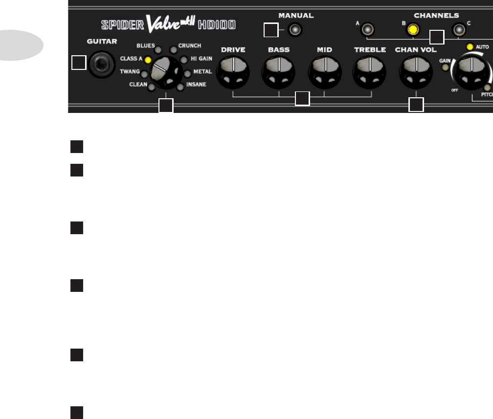
1 Guitar In – Plug your axe in here.
2 Amp Models – Spin this knob to select 1 of 16 Amp Models out of the box. All
Tone and FX controls will automatically be set to sound great with that model, so you can
just play! When you select an Amp Model, the LCD Display will show the model name
plus the current settings for Drive, Bass, Mid, Treble, Channel Volume and Reverb.
3 Manual Mode – Press this button to enter Manual Mode. When it’s LED is
on, all the front panel Tone knobs determine your Tone settings. Even if you select a new
Amp Model, the Tone settings remain the same as your current knob positions. When you
exit Manual Mode by selecting a new Preset, that Preset’s stored settings will take over.
4 Tone Controls – Drive is like a volume or gain knob on conventional guitar
amps; it controls how much “dirt” you get in your sound. Bass, Mid, and Treble controls
are customized for each Amp Model to give you optimal tonal control, just like the original
amp the model was based on. When you turn any of these knobs, the LCD Display will
show the current settings for Drive, Bass, Mid, Treble, Channel Volume and Reverb.
5 Channel Volume – This control is pre-Master Volume in the signal flow. It
helps you balance the volumes of your different Amp-and-FX setups that you store in your
Spider Valve MkII’s Presets. When you turn this knob, the LCD Display will briefly show
the current settings for Drive, Bass, Mid, Treble, Channel Volume and Reverb.
6 Channels – Press any of the A B C D Channel buttons to select a Preset in the
current User Bank. The selected Preset name will appear in the LCD Display. To initiate
a Save, push and hold one of these buttons for 2 seconds. *See Chapter 2•2 for details.
Front Panel Controls
45
2
3
1
6
Overview
1•3
7 Smart FX Controls – Spin one of these 3 knobs to select great FX, fast and
easy. Each FX knob lets you choose one of 3 primary or 3 secondary FX Models, for a total
of 18 possibilities, with up to 3 active at once.
The lit LED indicates the active effect, either amber or blue. If an effect’s settings have been
customized, its LED will be purple. *See Chapter 4•3 for more info on FX Customization.
Turning an FX knob all the way off disables the effect and resets any customization.
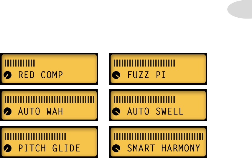
FX-1 Knob: selects Red Comp or Fuzz Pi, Auto Wah or Auto Swell, Pitch Glide or Smart
Harmony, with a pre-set range of settings for each effect.
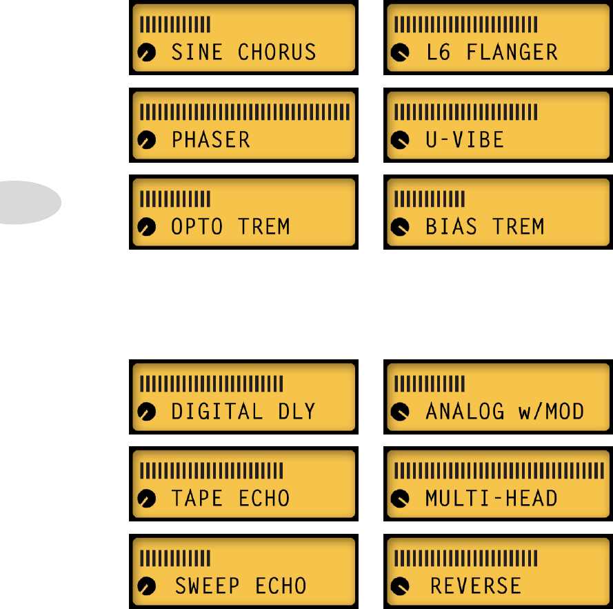
FX-2 Knob: selects Chorus or Flanger, Phaser or U-Vibe, Opto or Bias Trem, again with
a range of settings for each effect.
FX-3 Knob: selects Digital Delay or Analog Delay w/Mod, Tape Echo or Multi-Head,
Sweep Echo or Reverse, with a range of settings. The Tap LED flashes the delay time.
When you turn any of the 3 FX knobs, the Momentary FX Display will show you the
current FX Model name. To select the alternate model, turn the Presets knob while the
Momentary FX Display is showing. Your selection will be stored in that FX location per
saved preset.
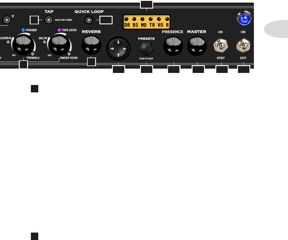
8 Tap – To set your tempo for time-based Mod and Delay FX, press the Tap button
at least twice at the desired tempo. When Tap is set to Don’t Control in Edit Mode, set
the Delay time or Mod speed manually and it will remain independent of the Tap tempo.
79
10
11
8
12
13
14 15 16 17

Overview
1•4
Hold Tap For Tuner – To enter Tuner mode, hold the Tap button for a few seconds.
The Tuner will appear in the LCD Display, along with each note you’re tuning. It will
indicate whether you’re sharp or flat via the graphic lines to the right or left, respectively.
When you’re in tune, the graphic ** symbols will be lined up in the center of the LCD.
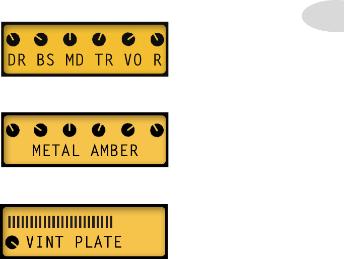
9 Reverb – When you adjust the Reverb knob, a bar graph will display the Reverb
Mix level for a few seconds in the LCD, along with the current Reverb Model name,
either Lux Spring or Vintage Plate. To toggle between the two Reverb Models, turn the
Presets knob left or right while the bar graph is displayed.
10
Quick Loop – Pressing this button puts you in Looper Control Mode. When
it’s lit, the Tap button becomes your one-button control for Recording, Overdubbing, loop
Playback and Stop. *See Chapter 5 for in-depth info on recording and playing loops.
11 4-way Navigation Disc – Press the Up, Down, Left, or Right arrows to
select a parameter that you’d like to change. The arrows are displayed in the LCD for each
function. *For in-depth info on the many Amp Model and FX parameters you can access
with this control, see Chapter 3 Editing.
12 Presets/Press To Edit – When in Preset Select Mode, turn this knob to
scroll thru 32 banks of presets. Push in the Presets knob to enter Edit Mode. This enables
you to set various parameters for all your FX, as well as select settings in Setup Mode and
perform other functions. *See Chapter 3 for more info.
13 LCD Display – The LCD (liquid crystal display) is your window into the
power of the Spider Valve MkII. Here you’ll see various “pages” as you adjust the various
controls, including Momentary Tone Display, Momentary FX Display, and numerous other
Parameter menus as you fine-tune your guitar sounds. The LCD is designed to give you
instant feedback on any parameter you’re currently adjusting.
14 Presence – This is a Presence control for the tube power amp. It works even if
you plug a POD X3 into the power amp, for example, using the Power Amp In jack.
15 Master Volume – Sets the Master output level of your Spider Valve MkII
power amp. This also controls the level of the Direct Output in Performance Mode.
16 Standby Switch – This switch puts the amp in standby mode when desired.
17 Power Switch – Flick this switch to power up your Spider Valve MkII.
Overview
1•5
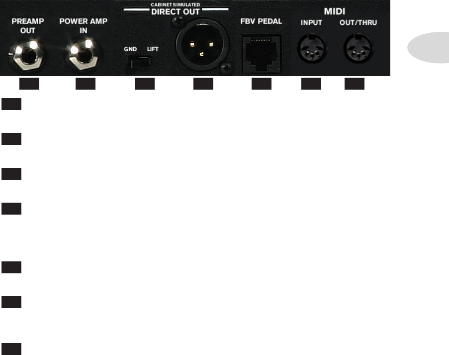
Rear Panel I/O
18 Preamp Out – Use the Preamp Out to send your Spider Valve MkII DSP Amp
and FX modeling output to an external power amp, guitar amp or FX device.
19 Power Amp In – Plug into your Bogner-designed power amp here. Some
players use a POD X3 or M13 as a front end, for example, driving the all-tube power amp.
20 Ground Lift – When using the Direct Out, you can lift the ground if desired.
This may help eliminate buzz when you have two different devices connected.
21 Direct Output – This jack is a Direct Output to connect your Spider Valve
MkII to a mixer, PA, computer DAW, recording interface or other line input equipment.
You can select Studio Mode or Performance Mode output via a Setup menu. See Chapter
3•4 for more details.
22 FBV Pedal Input – This jack is the standard Line 6 connector for FBV Foot
Controllers. You can now update your Spider Valve MkII’s firmware via FBV Mk II pedals.
23 MIDI Input – This is a standard MIDI Input jack. With a MIDI interface you
can send and receive Program Change and other MIDI messages to control your amp from
a computer. You can also update the amp’s firmware via MIDI.
24 MIDI Out/Thru – This is your MIDI Output jack. In addition to computer
interfacing you can daisy-chain multiple amps together and both amps will respond to
FBV foot controller messages (with v1.18 firmware or higher).
* For MIDI Program Change and CC info, see Appendix A: MIDI. You can also download
a comprehensive sysex MIDI spec at www.line6.com/manuals.
1918 20 21 22 23 24
Overview
1•6
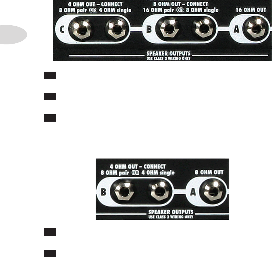
Speaker Outputs - HD100
A 16 Ohm Out – If you’re using one 16 Ohm cab, a 4x12 for example, connect
it to the single A Speaker Output.
B 8 Ohm Out – Use the two B Speaker Outputs to drive two 16 Ohm cabs, or
plug into one of the B outputs to drive a single 8 Ohm cab.
C 4 Ohm Out – If you’re using two 8 Ohm cabs, plug them into the two C
Speaker Output jacks; if using a single 4 Ohm cab, plug it into one of the C outputs.
Speaker Outputs - 112 / 212
A 8 Ohm Out – If you’re using one 8 Ohm cab, connect it to the single A Speaker
Output.
B 4 Ohm Out – If you’re using two 8 Ohm cabs, plug them into the two B
Speaker Output jacks; if using a single 4 Ohm cab, plug it into one of the B outputs.
Presets
2•1
Presets
Spider Valve MkII is ready to rock when you switch it on - just plug in your guitar and play.
By pressing a button or using the Nav Disc or Presets knob you can easily access every FX
parameter, the Looper, 128 savable presets, and ultimately customize your guitar sound.
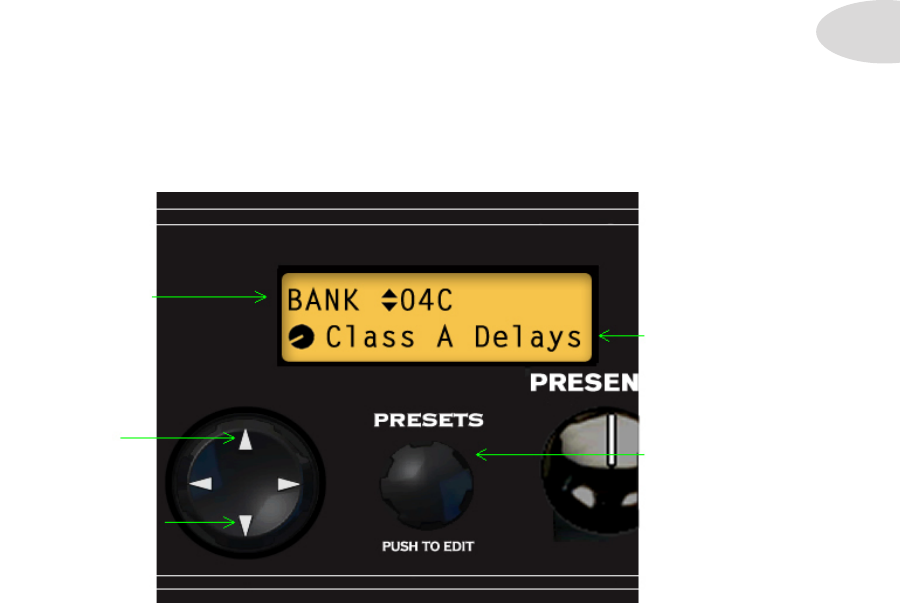
Preset Select
When Spider Valve MkII is first powered up it will be in Preset Select Mode. By simply
turning the Presets knob and using the 4-way Navigation Disc, you can select any User
Bank and Preset. You can also press any A B C D button to select a User Preset in the
current Bank, or use an FBV foot controller to navigate thru the 32 User Banks.
Here’s a basic navigation overview of Preset Select Mode:
Manual Mode
Pressing the Manual Mode button puts the amp in Manual Mode. This means that all
your settings, regardless of the saved settings, are determined by the physical positions of
the Drive, Bass, Mid, Treble, Channel Volume and Reverb knobs. To exit Manual Mode,
press the button again or load a preset via the Presets knob or one of the A B C D buttons.
• L/R Arrows on
4-way Nav Disc
select the Preset
(Bank & Channel)
• Up/Down
Arrows will scroll
through the next/
previous Bank
• Turn Presets
knob to select
next/previous
Preset from the
current Bank
• Current Preset
is displayed here
[Class A Delays]
Presets
2•2
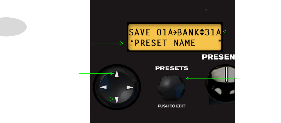
Saving
Once you’ve edited a preset to your liking, you’ll want to save it in one of the User Banks.
Here’s an overview of the Save routines for Spider Valve MkII:
• L/R Arrows on
4-way Nav Disc
select one of the
14 characters of
the Preset name
[it will flash]
• Up/Down
Arrows select
the next/previous
User Bank as the
Save destination
• Turn Presets
knob to change
the current
character in
Preset name
[push for quick
change of type]
• Current Preset
Save destination
[Bank 31 Chan A]
To save a preset:
• Press & hold the channel button of the current preset location - all 4 LEDs will flash
• Select the destination Bank by pressing the up/down arrows on the Nav Disc
• Rename the preset if desired - L/R arrows select character - Presets knob changes it
• Once your preset name is set, press a Channel button as your preset destination
• The LEDs will flash rapidly a few times indicating the Save is complete
• Your preset is now saved to the Bank and Channel location you’ve selected
Editing
3•1
editing
Edit Mode
In addition to standard Tone controls, Spider Valve MkII features a new Edit Mode that
enables you to perform deep editing of all your FX parameters. You can edit any available
parameter for FX1, FX2, FX3, Reverb, Gate, Boost, Volume, Loop and Setup.
For basic editing, it’s best to select your Amp Model first, or start with a pre-programmed
preset that’s close to the sound you want. Then adjust the Drive, Bass, Mid and Treble
controls. You’ll notice that when you touch a Tone control, all the Tone values and
Reverb level will be displayed in the LCD. This is called the Momentary Tone Display.
When you turn the Amp Model encoder, you’ll see the current Amp Model name in the
LCD. This is so you know which model is selected without looking at the encoder.
When you’re ready to add SmartFX to your preset, turn any of the 3 SmartFX knobs. You
can add 1 effect from each of the SmartFX per preset, in addition to Reverb.
To select an alternate FX Model for the current effect (or Reverb), turn the Presets knob
while the FX Model name is displayed in the LCD. The name will be displayed for 4
seconds every time you turn the knob, so if you change your mind, just touch the FX knob
again to wake it up - then turn the Presets knob left or right to select the alternate Model.
When you turn the Reverb knob, you’ll see the current Reverb Model name in the LCD
for a few seconds, along with a bar graph displaying the Reverb Mix level.
Editing
3•2
Use the L/R arrows to navigate thru the FX blocks. Use the up/down arrows to select the
various parameters in each block. To adjust a parameter value, turn the Presets knob.
Depending on the FX you’re editing, you’ll have a variety of parameters to adjust. These
include Routing, Mix, Tone, Feedback, Depth, Speed, Time and Tap Control, among
others that will be specific to each FX model.
A note about SmartFX
In Preset Select Mode, when you turn the FX1, FX2 or FX3 knobs to select effects, you’ll
notice that parameters have already been set up for you. These SmartFX provide you with
an instantly musical sound without having to tweak an effect’s individual parameters.
This makes it quick and easy to audition the various effects and not have to worry about
setting them up. When you hear an effect that you’d like to use for the current preset, you
can then enter Edit Mode to customize it to your personal taste.
*We’ll cover SmartFX in more detail, including customization, in Chapter 4 SmartFX.
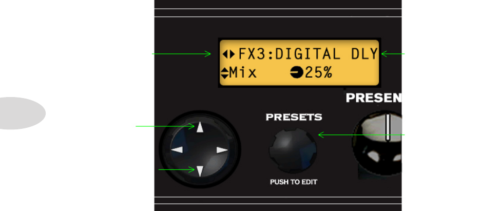
With each of your FX assigned, you’ll want to enter Edit Mode to tweak the individual FX
parameters. To do so, press the Presets knob. The LCD will look like this (for FX3):
• L/R Arrows on
4-way Nav Disc
take you thru
FX1, FX2, FX3,
Reverb, Gate,
Boost, Vol, Loop,
MIDI, Setup
• Up/Down
Arrows take you
thru the available
parameters of the
current selection
[Mix for FX3]
• Turn Presets
knob to adjust
the current
parameter
[Mix]
• Current Model
is displayed here
[Digital Delay]
Editing
3•3
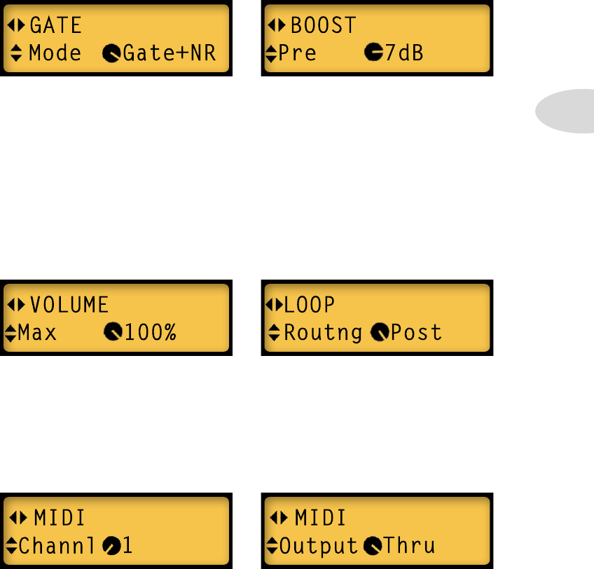
Gate
If you press the right arrow from the Reverb screen, you’ll see the Gate screen. Your Gate
Mode choices are Off (Gate is disabled), Gate (a standard noise gate), NR (a frequency
dependent noise reduction) or Gate+NR (both Gate+NR together). You can also adjust
Threshold and Decay settings. Gate parameters are saved with the individual preset.
Boost
We’ve included a new Boost with Spider Valve MkII, which is the next Edit Mode screen
to the right of Gate. Boost has 3 parameters: Pre, which lets you set the amount of Boost
before your signal hits the Amp Model, Post, which lets you set boost level after the Amp
Model, and Active, where your choices are On or Off. Boost is also saved per preset.
Vol
Press right arrow from the Boost screen to see Vol. If you use an FBV or expression pedal
to control Volume, you can set its parameters for Min (the minimum volume for heel
down), Max (the maximum volume for toe down) and Routing, which routes the volume
pedal pre or post Amp Model. Vol is saved per preset.
Loop
If you press right arrow from the Vol screen you’ll arrive at the Loop screen. This screen
is dedicated to Loop routing, and is saved per preset. Pre routes your loop audio before the
Amp Model; Post routes it after the Amp Model.
MIDI
Press right arrow from Loop to set your MIDI Channel and Output mode (Out or Thru).
Editing
3•4
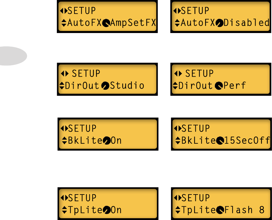
• For AutoFX your choices are AmpSetFX, which means your FX will change when
you change Amp Models, or Disabled, meaning your FX don’t change when you
change Amp Models. Turn the Presets knob left or right to make your selection.
Setup
In Setup Mode there are 5 screens: Auto FX, Direct Out, Back Light, Tap Light and
Version. To edit, press the Presets knob to enter Edit Mode, then press the L/R arrows
until SETUP is displayed. Press the up/down arrows to display the following in the LCD:
• Press the down arrow to edit your Direct Out setting. Your choices are Studio, which
uses the DSP output, or Performance, which taps off the power amp transformer.
• Press the down arrow to edit BkLite. Your choices are On, meaning the LCD will
always be lit, or 15SecOff, which means the LCD back light will turn off after 15
seconds of inactivity. Turn the Presets knob left or right to make your selection, then
press the down arrow to go to the next screen.
• For TpLite your choices are On, meaning the TAP light will always flash the current
tempo, or Flash 8, which means the TAP light will flash 8 times after the most recent
activity, then it will stay off. Turn the Presets knob to make your selection.
• Press right arrow for the fifth Setup screen. It displays the current Flash Memory
Version you’re running in your Spider Valve MkII. This display cannot be edited.
SmartFX
4•1
smart FX
As we mentioned in Chapter 3 Editing, FX1, FX2 and FX3 are SmartFX. SmartFX are
designed to give you instant great-sounding FX without having to tweak their parameters.
Of course you can enter Edit Mode at any time and adjust FX settings to your liking, but
it’s easiest to audition SmartFX by simply turning one of the 3 FX knobs.
When you turn a SmartFX knob you’ll hear a variety of pre-programmed settings that
change according to the knob’s ‘swoosh’ position. Swoosh is our term for the range of
travel between each effect’s starting point and ending point on the SmartFX knob.
For each SmartFX knob you can select 1 of 3 primary or 3 secondary FX models. For
example, turn the FX1 knob clockwise from the off position. The first LED will light up
amber, incidating the primary Gain model Red Comp is active. At the same time you’ll
see RED COMP displayed in the LCD with a bar graph indicating its swoosh position.
To select the secondary Gain model, turn the Presets knob to the right while RED COMP
is displayed in the LCD. FUZZ PI will now be displayed and the FX1 LED will turn blue.
To change back to Red Comp, move the FX1 knob slightly to wake it up. You should see
FUZZ PI in the LCD - turn the Presets knob to the left and Red Comp will load again.
Above are the primary and secondary FX1 models for the Gain, Auto and Pitch locations.
The small knob at min position indicates primary model; max position indicates secondary.
The bar graph displays the selected effect’s current swoosh position on the FX1 knob.
SmartFX
4•2
Again the small knob graphic indicates primary model (min) or secondary model (max).
The bar graph indicates the selected effect’s current swoosh position on the FX2 knob.
Here are the primary and secondary SmartFX models for the Chorus, Phaser and Tremolo
locations on the FX2 knob:
Here are the primary and secondary SmartFX models for the Delay, Tape Echo and Sweep
Echo memory locations on the FX3 knob:
SmartFX
4•3
Reverb isn’t in the SmartFX group, but it also features a primary and secondary model,
as illustrated below. Like the SmartFX, you select the model by turning the Presets knob
when the Reverb model name is displayed in the LCD. The difference is, the bar graph for
Reverb indicates its Mix level, which matches the Reverb knob position when you turn it.
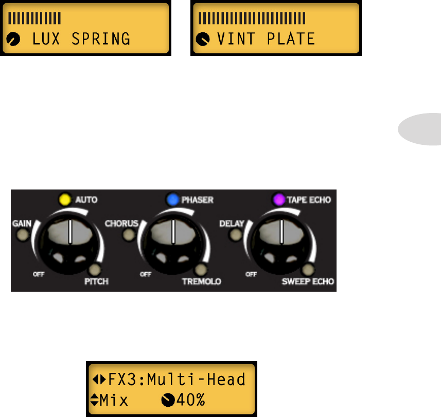
Smart FX Customization
In addition to editing FX in a preset, as outlined in Chapter 3 Editing, you can also
customize the individual parameters of one effect per FX knob, so that when you select
that effect in a preset, your settings will be recalled. Customization settings are stored with
each preset. When a SmartFX model has been customized, its LED will light up purple
instead of amber or blue. Here’s an example of what you might see on the front panel:
• FX1: Auto Wah
[Amber = primary]
• FX2: U-Vibe
[Blue = secondary]
Since the FX3 LED is purple, you know it’s been customized. To determine whether the
FX3 model is Tape Echo (primary) or Multi-Head (secondary), you can either touch the
FX3 knob to wake it up or press the Presets button to enter Edit Mode and the model name
will be displayed. Here’s what the FX3 Edit screen would look like for the Mix parameter:
• FX3: Tape Echo or Multi-Head
[Purple = customized]
Notice the knob graphic instead of a swoosh graphic - this Mix has been customized.
SmartFX
4•4
Here are a few important points to remember regarding SmartFX customization:
• In Edit Mode, if you change any parameters for one of the SmartFX, your settings
will remain fixed where you set them, even when you turn the SmartFX knob
• Parameters that you do not change will default to the pre-programmed SmartFX
settings for that effect
• Only 1 effect per SmartFX knob can be customized at a time (its LED will be purple)
• SmartFX customization settings are saved with each preset
• If you turn the SmartFX knob to the Off position, customization will be lost and all
effects for that SmartFX knob will revert to the default settings
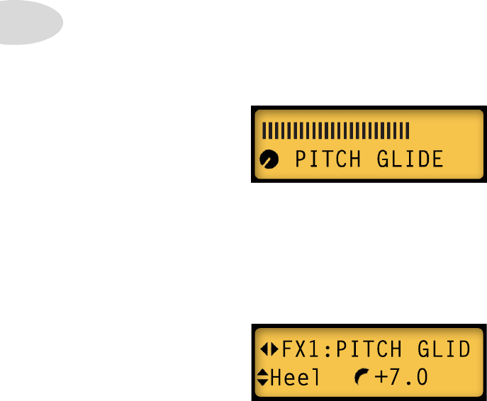
To see what the individual settings are, select a setting on the FX1 knob, press the Presets
knob to enter Edit Mode, then use the up/down arrows to navigate thru the various Pitch
Glide parameters.
If you decide to customize your Pitch Glide settings, keep in mind that the note pitch will
be determined by a combination of Heel value, Toe value, and Pedal Position. With no
pedal connected and POS value set at 0, the Heel value determines the note you hear.
Pitch Glide Tips
When you turn the FX1 knob to the Pitch position, the Pitch Glide effect will be activated.
Listen as you turn the FX1 knob slowly thru all the different SmartFX settings. Along with
your original note, you’ll hear a 2nd note 2 octaves down, 1 octave down, then -9, -7, -5,
-4, -3, +3, +5,+7, +9 (in semitones), 1 octave up and 2 octaves up. Mix is set at 44%.
For example, with Heel at +7 and POS at 0, you get a 5th note, which is 7 half steps up.
SmartFX
4•5
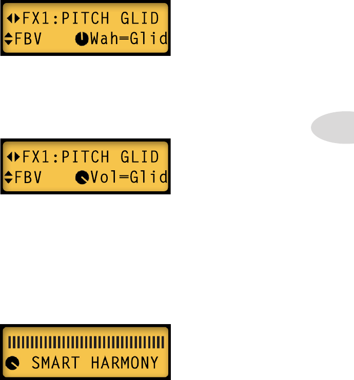
To control the Pitch Glide effect with an FBV pedal, enter Edit Mode and navigate to the
Pitch Glide FBV parameter. Select Wah=Glid or Vol=Glid, depending on which pedal
setting you’d like to use to control the Pitch Glide. Keep in mind the note you hear will
always be the Position of your pedal, relative to the Heel and Toe values.
When Wah=Glid, if you switch the wah pedal off, the pedal will control volume as usual.
If you switch the Stomp switch on, the volume pedal will switch to Pitch Glide again.
Make sure your pedal volume is up all the way when you use the Stomp switch, however,
because once the Pitch Glide takes over the wah pedal, you can’t adjust volume unless
you’re using an external expression pedal for volume.
When you set the FBV parameter to Vol=Glid, you’ll have no volume control via the
pedal, since it will be controlling Pitch Glide. If you switch to wah, the pedal will control
wah as usual, and your volume will always be at 100%.
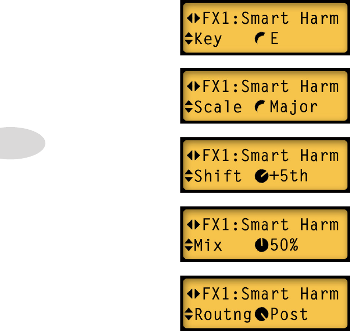
Smart Harmony Tips
To use the Smart Harmony effect, first select Pitch Glide by turning the FX1 knob to the
Pitch position. While the LCD displays the name Pitch Glide, turn the Presets knob to
the right - Smart Harmony will replace it.
Now listen to the various Smart Harmony settings by turning the FX1 knob while you
play an open E string, for example. First you’ll hear a low octave, then a few low harmony
notes, followed by some higher harmony notes up to an octave above your open E.
SmartFX
4•6
* Notice the two top screens display a swoosh graphic to the left of E and Major. This means
the Key and Scale settings are the Smart FX defaults and haven’t been customized. The
Shift and Mix parameters display a knob graphic, indicating they have been customized.
Routing always displays a knob graphic for Pre or Post.
Using the Smart Harmony settings above, if you play some single note riffs on your guitar
in the key of E you’ll hear a 5th note along with every note you play. With the Mix level
at 50%, the two notes should be equally balanced in volume. Give it a try.
• Select any Key by
turning the Presets
knob
• Routing can be
either Pre- or Post-
Amp Modeling
• Set the balance of your
dry & harmony note
with the Mix control
• Select the harmony
note Shift by turning
the Presets knob
• Select any of the
available Scales for the
Key you’ll be playing in
If you want to experiment with your own Smart Harmony settings, you’ll want to enter
Edit Mode. With Smart Harmony selected, here are the various Smart Harmony edit
screens that will be available for tweaking:
SmartFX
4•7
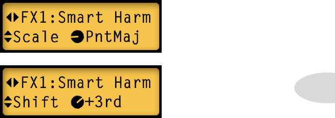
Now let’s try a different scale and see how Smart Harmony works. We’ll keep the settings
the same for Key (E), Mix (50%) and Routing (Post). But let’s set the Scale to pentatonic
major and Shift to +3rd.
Use the up/down arrows to display Scale, then turn the Presets knob to display PntMaj.
Use the up/down arrows again to display Shift, then turn the Presets knob to set it to +3rd.
Your Scale and Shift screens should look like this:
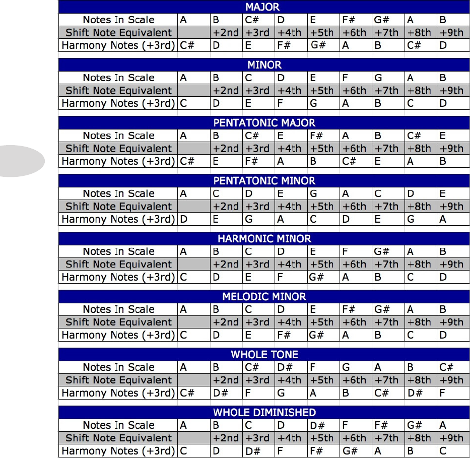
Now before you play anything, here’s a tip to help you understand what notes make up any
scale you might select. Set the Mix parameter to 100%, then navigate back to the Shift
screen. Set Shift to +None and play an open low E note - it should sound normal.
Now turn the Presets knob to the right one click at a time and play a single E note with
each click. Your notes will shift to +2nd, +3rd, +4th, +5th, +6th, +7th, +8th and +9th.
As you play your E note the notes you hear will be E (+None), F#, G#, B, C#, E, F#, G#
and B. Guess what? That’s your pentatonic major scale.
Now set your Scale and Shift values back to where they were in the graphic LCDs above
and play the 9 notes we just experimented with. Your harmony notes should be right in
tune. Improvise some single note riffs in the key of E, using only those same notes in any
combination. The harmony notes should be in perfect tune with your riffs.
Change the Shift parameter to +4th and play more riffs, again using only those 9 notes.
They should be in perfect harmony. Some Shift values like +2nd might not sound so
musical, but in most cases the Smart Harmony notes will sound pretty good.
If you have a degree in music theory, you already know what these scales are all about, but
if you’re a self taught rock’n’roller, do some experimenting and see what happens.
For a reference to all the Smart Harmony scales, check out the table on the next page.
SmartFX
4•8
Smart Harmony Scales
Looper Control Mode
5•1
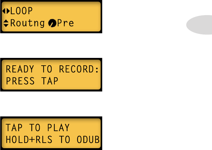
• When you’re ready to record your loop, press the Tap button. Whatever you play
will be recorded (up to 14 seconds max). The LCD will look like this:
LOOPer COntrOL mOde
Spider Valve MkII’s Quick Loop function enables you to easily record a guitar loop for
jamming or auditioning Presets. To enter Looper Control Mode, press the Quick Loop
button. You’ll notice that both the Tap button and the Quick Loop button remain lit. In
Looper Control Mode mode, all you have to do is press the Tap button to control various
functions of the looper, including Record, Overdub, Play, Stop and Clear. You can also
edit presets and save your changes while your loop continues to play back.
Auditioning & Editing Presets - To record a loop and play it back to audition
and edit Spider Valve MkII presets, plug in your guitar and follow these steps:
• Press the Presets button to enter Edit Mode. Use the left arrow on the Nav Disc
to navigate to the LOOP screen. Set Routing to Pre by turning the Presets knob.
• Now press the Quick Loop button to enter Looper Control Mode. The button will
flash and the Tap button will remain lit; the LCD display will look like this:
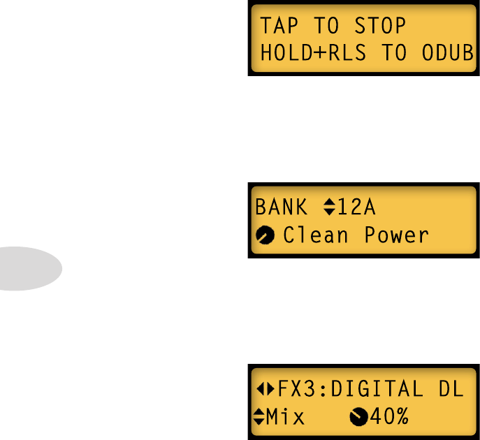
• To stop recording and immediately play back your loop, press Tap again. This sets
your loop out-point and sends your loop back to the beginning in Play mode.
Looper Control Mode
5•2
• To stop loop playback, press the Quick Loop button then press the Tap button. To
clear your loop, press and hold Tap for at least 3 seconds.
• To exit Looper Control Mode, press the Quick Loop button again. Its LED will
turn off and the Tap button will return to normal operation.
To save your edited settings, press and hold any Channel button for a few seconds, rename
your preset and select a Bank destination for it, then press the desired Channel button to
complete the save, as described in Chapter 2•2.
Since your loop playback is set to Pre, you can select any preset you want and your guitar
sound will change the same as if you were playing live. Press the Quick Loop button to
temporarily exit Looper Control Mode. Select any of the A B C D Channel presets to hear
what they sound like. You can even change Banks via the up/down arrows. This is a great
way to audition sounds.
If you want to stop playback, press Tap again. If your loop sounds good to you and you’re
ready to check out some presets, let it play. We’ll get into overdubbing on page 5•3.
Now let’s do some preset editing. If you want to stop your loop for a minute, press the
Quick Loop button to re-enter Looper Control Mode, then press Tap. When you’re ready
to go again, press Tap to play your loop, then press the Presets knob to enter Edit Mode.
Use the left/right arrows to navigate to the FX3 screen to edit Delay Mix. If you don’t have
a delay on, turn the FX3 knob to select one.
Feel free to navigate to any FX parameter and tweak it, change your Tone controls, even
load a different Amp Model, all while your loop continues to play.
Looper Control Mode
5•3
Looper Tips
For those of you who might be interested in multiple overdubbing and more advanced
control of the looper, Spider Valve MkII can accommodate you. Although all Quick Loop
functions are assigned to one button, which is Tap, we’ve added a second layer of control
by programming a ‘quick press’ and a ‘press and hold’ functionality to the Tap button.
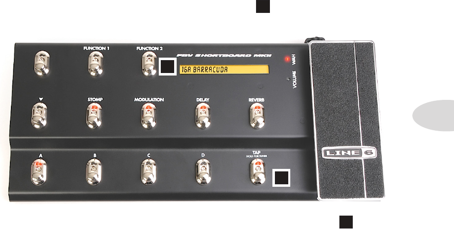
Of course it isn’t easy to play guitar with both hands and press buttons at the same time,
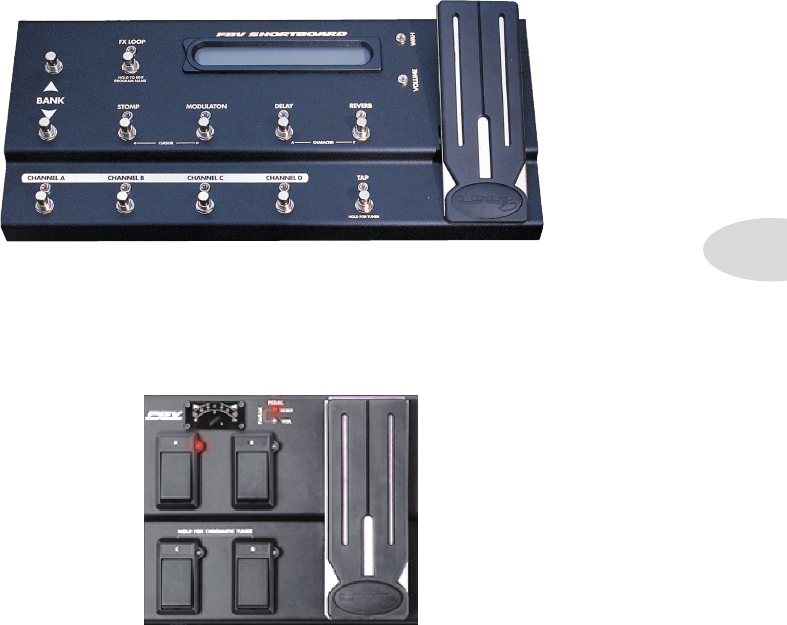
so you might want to use an FBV foot controller to control your looper. Using the Tap
switch on an FBV MkII Shortboard, for example, labeled in the graphic below, here are
a few tips you can try with your Spider Valve MkII when you’re in Looper Control Mode:
F
T
T
Record/Overdub – first press the Quick Loop button (or Function 2 ); now to
record your initial loop, set an accurate out-point and begin overdubbing immediately...
• Step on the Tap switch to begin recording your loop, but don’t release the switch
• With your initial take in progress, when you’re ready to set your loop out-point and
record your first overdub, lift your foot off the Tap switch
• Your loop will play back from the beginning and you’ll be in Overdub mode,
recording over your original loop
• If you continue to let it roll, you’ll add a new overdub with each pass; to stop
overdubbing and enter Playback mode, briefly press the Tap switch
You can now jam along with your loop, or press the Tap switch again to stop playback.
F
Looper Control Mode
5•4
Set Out-Point/ Arm Overdub – to accurately set your loop out-point and arm
Overdub mode in advance of recording your next layer of guitar, try this:
• Step on Tap briefly and release to begin recording your loop
• Step on Tap at the out point and hold - you’ll enter Playback mode immediately
• When you’re ready to record an overdub, release the Tap switch to enter Overdub
mode; if you continue to let your loop roll, each time it loops around you’ll be adding
another overdub layer
• To exit Overdub mode and immediately enter Playback mode, briefly step on the
Tap switch; if you’d rather stop playback, step on the Tap switch and hold
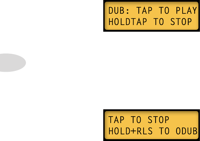
Arm Overdub From Playback – after you’ve recorded your initial loop and set the
out-point, you can enter Overdub mode at any time. With your loop playing back:
• Press and hold the Tap switch - when you’re ready to record, release the Tap switch
and you’ll enter Overdub mode
• To enter Playback mode, press the Tap switch - to stop playback, press Tap again
Exit Overdub Mode/ Stop Playback – if you’re in Overdub mode and you’d like to
stop recording but keep playback going until a specific stop point:
• Record your initial loop as usual and enter Overdub mode using any of the previously
described methods
• With your overdub in progress, when you’re finished overdubbing, press and hold the
Tap switch - your loop will be playing back but not recording
• To stop playback, lift your foot off the Tap switch - your loop will stop immediately
Foot Control
6•1
FBV Options
If you have an FBV Shortboard or Longboard, all the standard FBV functions will control
the Spider Valve MkII as expected, including Tuner, A B C D Preset select, Bank Up &
Down, Mod, Delay, Boost, Reverb and Tap Tempo. The FX Loop switch activates the
Boost, which is saved per preset in Spider Valve MkII. The Volume or Wah pedal can also
be assigned to control Pitch Glide, and Volume can be assigned a Min and Max value per
preset. For more info see Chapter 3 Editing and Chapter 4 Smart FX.
Another important advantage to using an FBV is you can control Quick Loop functions
with the Tap button. This greatly expands the possibilities for recording, overdubbing and
live performances when in Looper Control Mode. See Chapter 5 for more info on how
to use your FBV to record and play back loops in Looper Control Mode.
The FBV Express and FBV Express MK II will also control many Spider Valve MkII
functions such as Tuner, Preset Select, Tap Tempo, and a few FX assignments for the pedal.
FOOt COntrOL
Foot Control
6•2
Firmware Updates: If you have an FBV Mk II series foot controller, you can update
your Spider Valve Mk II’s firmware via USB and RJ45 connector when connected to your
computer, should new versions of Flash Memory be released. You can also update using
the MIDI connections on the Spider Valve MkII rear panel. Be sure to check the Line 6
website for the latest info on firmware updates and instructions for updating your Spider
Valve MkII. You can also download the FBV Mk II Advanced Guide, which provides
more details on the new FBV Mk II series foot controllers.
We’ve also added new switch functionality to the FBV Express MkII, as described below:
• To enter Tuner Mode, press and hold the currently lit Channel switch
• Press and hold either the A+B or C+D switches to enter Looper Control Mode; the
lit Channel switch will now control the Loop, like the front panel Tap switch
• To exit Looper Control Mode, press the A+B or C+D switches again
• You can exit Looper Control Mode while your loop is playing, change your preset
by pressing any Channel switch, then enter Looper Control Mode again at any time
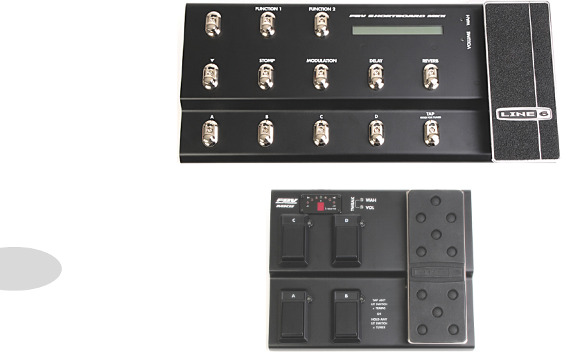
FBV Shortboard MkII: The new FBV Shortboard Mk II features an extra switch labeled
Function 2. This switch toggles Quick Loop on or off, and has the same functionality
as the Quick Loop switch on the front panel of your Spider Valve MkII. It makes it easy
to enter and exit Looper Control Mode from the FBV. The Function 1 switch turns the
Boost on and off; it’s state is saved with every preset.
Appendix A: MIDI
A•1
aPPendiX a: midi
In this chapter we’ll provide you with reference tables of MIDI CC and Program Change
numbers that control basic functions of your Spider Valve MkII. When connected to a
computer using an FBV MkII foot controller (or using MIDI cables and a MIDI interface),
you can send and receive MIDI messages between your Spider Valve MkII and sequencer.
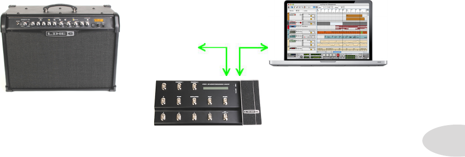
Here’s a guide to setting up your gear when interfacing with your computer work station.
Connect your Spider Valve MkII (v1.18 or higher) to your FBV MkII foot controller using
an RJ45 FBV cable. Connect a USB cable from the FBV MkII to your computer. Launch
your sequencer and make sure your FBV MkII shows up as a MIDI input/output port.
Within your sequencer project, create a MIDI track with its inputs and outputs assigned to
the MIDI channel that represents your FBV Mk II interface. Then either manually insert
MIDI CC values or PGM Change messages directly into the MIDI track’s timeline, or put
the track in record, roll it from the top and make the desired changes on the Spider Valve
MkII itself. As your song plays, you’ll see your actions appear in the MIDI track.
Once your MIDI commands are recorded, simply put the track in playback mode and play
back the track. Your Spider Valve MkII will respond to all the recorded MIDI commands.
Connect an FBV*
cable between
your Spider Valve
MkII and your FBV
MkII Connect a USB
cable between
your computer
and your
FBV MkII
Basic MIDI Setup
*Or you can use
MIDI cables and a
MIDI interface
Amp Daisy Chaining
For those of you who might like to use two Spider Valve MkII amps in your stage rig, we’ve
implemented MIDI to enable multi-amp daisy chaining. This is especially effective when
using an FBV MkII series foot controller to control both amps. To set this up, connect
your master Spider Valve MkII MIDI Out to the slave MIDI In. Connect your FBV MkII
to the master amp as usual. Any of the standard FBV functions will control both amps,
such as Channel select, FX on/off, Wah and Volume. Also, any adjustments you make
on the master amp’s front panel will be reflected in the slave, such as FX or Tone tweaks.
Appendix A: MIDI
A•2
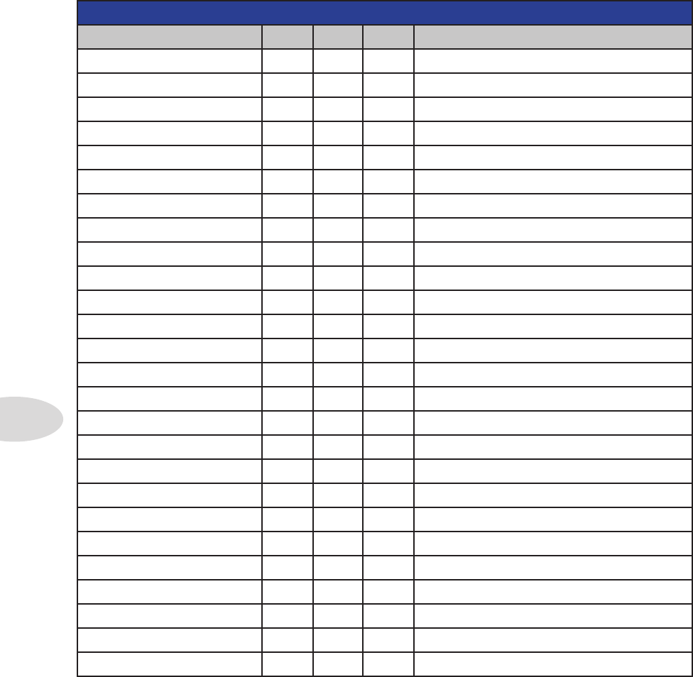
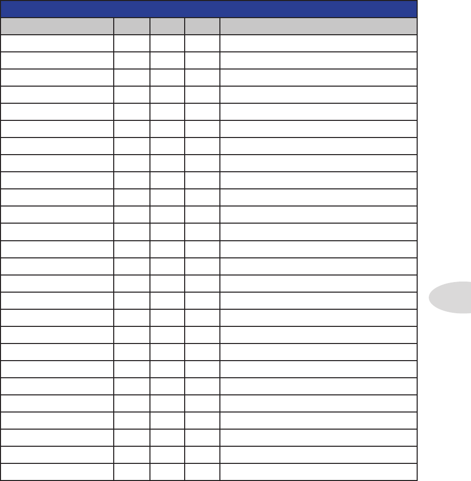
MIDI CC REFERENCE TABLE 1
Parameter CC # Min. Max. Notes
Wah Position 4 0 127
Volume 7 0 127
Pan 10 0 127 0=Left; 64=Center; 127=Right
Amp Model w/ defaults 11 1 16 0=Bypass
Amp Model w/o defaults 12 1 16 0=Bypass
Drive 13 0 127
Bass 14 0 127
Mid 15 0 127
Treble 16 0 127
Channel Volume 17 0 127
Reverb Mix 18 0 127
Gate Enable 22 0 3 0-Off; 1=Gate; 2=NR; >=3=Gate+NR
Gate Threshold 23 0 127 -96 dB to 0 dB
Gate Decay 24 0 127 0 to 100%
Stomp Enable 25 0 127 0-63=Off; 64-127=On
Boost On/Off 26 0 127 0-63=Off; 64-127=On
Stomp SmartFX 27 0 127 Swoosh position
Delay SmartFX 30 0 127 Swoosh position
Delay Mix 34 0 127
Reverb Enable 36 0 127 0-63=Off; 64-127=On
Reverb Model 37 19 20 0=Off; See Reverb Models table
Reverb Routing 41 0 127 0-63=Pre; 64-127=Post
Volume Pedal Min. 46 0 127
MIDI CC REFERENCE TABLE 2
Parameter CC # Min. Max. Notes
Volume Pedal Max 45 0 127 Vol or Wah can control Pitch Glide
Volume Routing 47 0 127 0-63=Pre; 64-127=Post
Mod Enable 50 0 127 0-63=Off; 64-127=On
Mod Mix 56 0 15 #11=Default Settings #12=Model Only
Mod Routing 57 0 127 0-63=Pre; 64-127=Post
Tap Tempo 64 0 127 value ignored
Tuner Mode 69 0 127 0-63=Off; 64-127=On
Pitch Glide Enable 72 0 127 0-63=Off; 64-127=On
Stomp Routing 74 0 127 0-63=Pre; 64-127=Post
Stomp Model Select 75 1 6 0=Off; see FX-1 Models table
Delay Routing 87 0 127 0-63=Pre; 64-127=Post
Delay Model Select 88 13 18 0=Off; see FX-3 Models table
Delay Enable 28 0 127 0-63=Off; 64-127=On
Mod SmartFX 96 0 127 Swoosh position
Appendix A: MIDI
A•3
MIDI CC REFERENCE TABLE 2
Parameter CC # Min. Max. Notes
Volume Pedal Max 45 0 127 Vol or Wah can control Pitch Glide
Volume Routing 47 0 127 0-63=Pre; 64-127=Post
Mod Enable 50 0 127 0-63=Off; 64-127=On
Mod Mix 56 0 15 #11=Default Settings #12=Model Only
Mod Routing 57 0 127 0-63=Pre; 64-127=Post
Tap Tempo 64 0 127 value ignored
Tuner Mode 69 0 127 0-63=Off; 64-127=On
Pitch Glide Enable 72 0 127 0-63=Off; 64-127=On
Stomp Routing 74 0 127 0-63=Pre; 64-127=Post
Stomp Model Select 75 1 6 0=Off; see FX-1 Models table
Delay Routing 87 0 127 0-63=Pre; 64-127=Post
Delay Model Select 88 13 18 0=Off; see FX-3 Models table
Delay Enable 28 0 127 0-63=Off; 64-127=On
Mod SmartFX 96 0 127 Swoosh position
Appendix A: MIDI
A•4
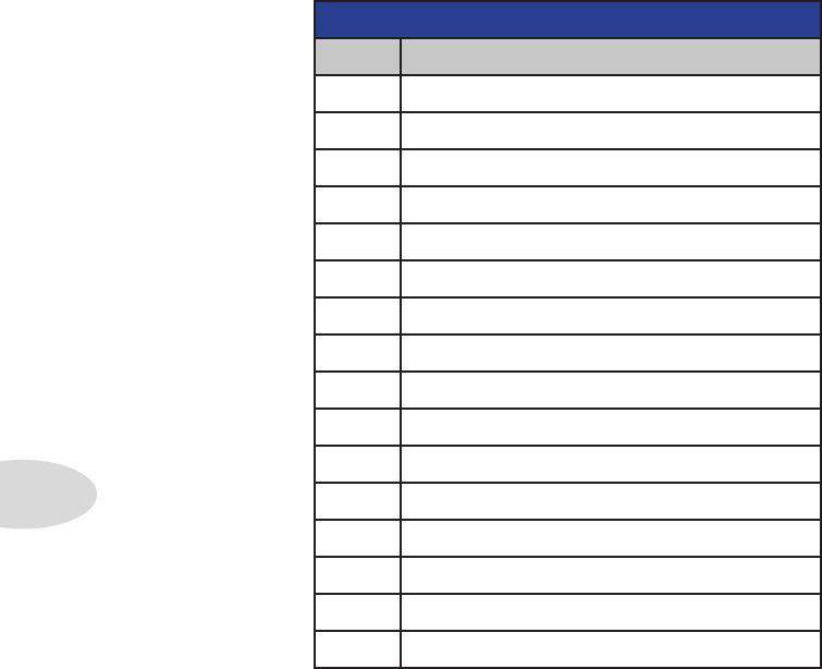
AMP MODELS (MIDI CC 11 or 12)
Value Amp Model Name
0 Clean Amber
1 Clean Blue
2 Twang Amber
3 Twang Blue
4 Class A Amber
5 Class A Blue
6 Blues Amber
7 Blues Blue
8 Crunch Amber
9 Crunch Blue
10 Hi Gain Amber
11 Hi Gain Blue
12 Metal Amber
13 Metal Blue
14 Insane Amber
15 Insane Blue
Amp Model Select
A MIDI CC of 11 Selects the Amp Model with Default settings. A CC of 12 selects the
Amp Model only, with no change to the Tone controls, FX or Channel Volume.
With CC 11 inserted on your MIDI track, select an Amp Model by entering a value of 0
through 15. A corresponding Cab Model will automatically load with the Amp Model.
When using CC 12, the current settings for Drive, Bass, Mid, Treble and Ch Vol remain
unchanged.
Appendix A: MIDI
A•5
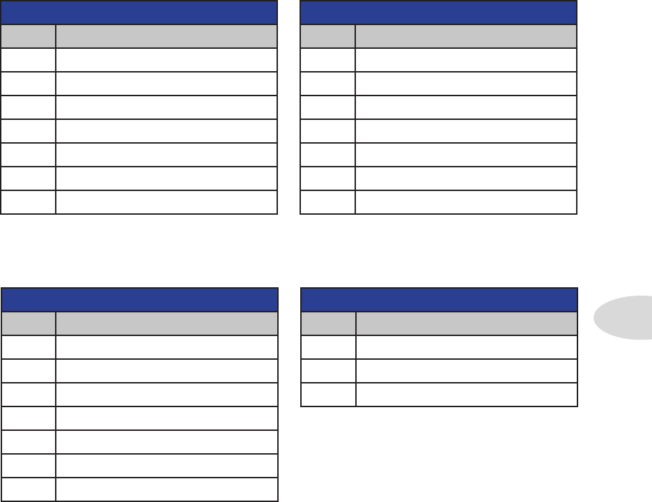
FX-1 MODELS (MIDI CC 75)
Value FX Model Name
0 Off
1 Red Comp (Gain)
2 Fuzz Pi (Gain)
3 Auto Wah (Auto)
4 Auto Swell (Auto)
5 Pitch Glide (Pitch)
6 Smart Harmony (Pitch)
FX-2 MODELS (MIDI CC 58)
Value FX Model Name
0 Off
7 Sine Chorus (Chorus)
8 L6 Flanger (Chorus)
9 Phaser (Phaser)
10 U-Vibe (Phaser)
11 Opto Trem (Tremolo)
12 Bias Trem (Tremolo)
FX-3 MODELS (MIDI CC 88)
Value FX Model Name
0 Off
13 Digital Delay (Delay)
14 Analog w/Mod (Delay)
15 Tape Echo (Tape Echo)
16 Multi-Head (Tape Echo)
17 Sweep Echo (Sweep Echo)
18 Reverse (Sweep Echo)
REVERB MODELS (MIDI CC 37)
Value Reverb Model Name
0 Off
19 Lux Spring
20 Vintage Plate
FX Model Select
Use the MIDI CC numbers indicated in the tables below to select the FX and Reverb
Models for FX-1, FX-2, FX-3 and Reverb. For example, CC19 value 10 is U-Vibe.
This works the same way as Amp Models. Insert the appropriate CC, for example CC 19
for Reverb, then add a value of 19 to call up the Lux Spring model or 20 for Vintage Plate.
Appendix A: MIDI
A•6
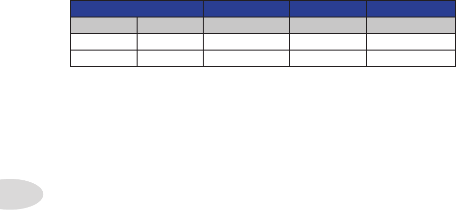
Preset Select
Spider Valve Mk II User Presets are comprised of 32 Banks of A B C D Channels.
To call up a particular User Preset, insert a Program Change value of 0-127. *0 would be
Preset 1A, 1 would be 1B, 4 would be 2A, 5 would be 2B, and so on, up to 127 for 32D.
PRESET SELECT
Bank MSB Bank LSB Program Range Program Bank Program Number
0 0 0-127 User Presets *1A-32D
0 1 0-15 Amp Models

Appendix B: Amp Models
B•1
aPPendiX B: amP mOdeLs
Here’s a brief reference guide to the 16 Amp Models in your Spider Valve MkII:
Clean Amber - Based on the clean channel of the Marshall® JCM 900, the first true
modern high gain amp from Marshall®. Select Clean Amber to get crisp, amazing clean
tones, great warm jazz tones, and all the high-end shimmer you’ll need with a generous
amount of bottom end.
Clean Blue - This amp model was developed to emulate those late 60s and early 70s
clean tones. We modeled a 1973 Hiwatt® custom 100, then extended the tone control range
and tightened up the low end for that big, ringing sound.
Twang Amber - This model draws on our analysis of mid 60s Fender® amps, in particular
the blackface ’65 Twin Reverb®. We wanted that classic, glassy high end tone, with enough
snap and bite for some serious chick’n pick’n. Things don’t get too crunchy until you reach
the top range of the Drive knob.
Twang Blue - There’s nothing like the sound of the classic Fender® blackface Deluxe
Reverb®, the Holy Grail for many blues, country and roots rockers.
Class A Amber - Ready, steady....GO! This amp model is based on a Vox® AC-30
amplifier with an updated and expanded TBX tone control circuit. We wanted to capture
that early pop rock tone that many British invasion bands are so well known for.
Class A Blue - There are some great modern amps out today based on the legendary
tones of yesteryear. Here’s our take on the EL84 circuit of a Divided By 13 9/15 Model.
Blues Amber - This model is inspired by that famous vintage tweed sound we all know
and love. We evaluated a ’53 Fender® wide panel Deluxe and this is what we came up with.
Blues Blue - Blues Blue is based on a Gretsch® 6156, a 1960 1x10 combo from the days
when rock’n’roll took the blues to a new level. Add some reverb and a slap echo and be-
bop-alu-la!
* All product names are trademarks of their respective owners, which are in no way associated or affiliated with Line 6. These product
names, descriptions and images are provided for the sole purpose of identifying the specific products that were studied during Line 6’s sound
model development. Hiwatt® is a registered trademark of Fernandes Company, Inc. FENDER®, Twin Reverb, Deluxe Reverb and
Bassman are registered trademarks of Fender Musical Instruments Corporation.VOX® is a registered trademark of Vox R&D Limited.
MARSHALL® is a registered trademark of Marshall Amplification Plc. GRETSCH® is a regustered trademark of Fred W. Gretsch
Enterprises, Ltd.

Appendix B: Amp Models
B•2
Crunch Amber - This sound was crafted during our studies of the ‘68 Marshall® Plexi
50 Watt, which was used by a number of early metal bands. Crunch Amber provides a wider
range of tone control settings than the original jumpered Marshall®, allowing you to bump
up the mids even at the highest Drive settings.
Crunch Blue - Here’s our inspired interpretation on a 2005 Orange® AD-30TC, a 30
watt, Class A head that oozes pure Brit rock tone, taking 60s crunch to a new level.
Hi Gain Amber - Plexi On Fire! This amp model is based on a ‘68 Marshall® Plexi 100
watt with a few added extras; the combination of a Variac and the jumpered input channels
creates that infamous brown sound that will feel like flames are shooting out the input jack!
Hi Gain Blue - Hi Gain Blue was inspired by the Diezel® Herbert, the 180 watt Ducati
of high performance guitar amplifiers, featuring a huge, tight low end.
Metal Amber - For this amp model we took the classic Mesa/Boogie® Dual Rectifier®
and added a few enhancements. The resulting Amp Model has a definite modern flavor.
This monster truck of tone delivers a bottom end that’s big, powerful, tight and fast. Use
Metal Amber to get a punchy, high gain Metal sound.
Metal Blue - This model was created to deliver an aggressive high gain sound. It features
a unique Mid control that will sweep though an entire spectrum of tone on one knob. With
the Mid knob is set to minimum, the distortion exhibits Fuzz pedal characteristics. When
set to noon, it mimics the creamy modern high gain amp tones. When turned up to max, it’s
reminiscent of that maxed out Class A sound. Of course there are all the places in-between...
Insane Amber - This model is our “dialed in for shredding” version of the Mesa/Boogie®
Dual Rectifier® red channel. It combines the intensity and impact of Metal Amber, but
delivers more midrange and teeth for that bone-crushing, brain piercing insane grind.
Insane Blue - Our goal with Insane Blue was to provide you with as much input gain
distortion as possible short of complete meltdown. You get an obscene helping of distortion,
while still retaining tonal definition and character. As a result, you get way more bottom
end and cabinet character than other small amps. Crank up the Drive control and prepare
to dominate!
* All product names are trademarks of their respective owners, which are in no way associated or affiliated with Line 6. These product
names, descriptions and images are provided for the sole purpose of identifying the specific products that were studied during Line 6’s sound
model development. ORANGE® is a registered trademark of Orange Personal Communications Services Ltd. MARSHALL® is a regis-
tered trademark of Marshall Amplification Plc. MESA/BOOGIE® and RECTIFIER® are registered trademarks of Mesa/Boogie, Ltd.
DEIZEL® is a regustered trademark of Deizel GMBH.

Appendix C: Maintenance
C•1
aPPendiX C: maintenanCe
The Spider Valve MkII 112 and 212 combo amps include two 12AX7-B preamp tubes and
two matched 5881 (6L6) power amp tubes. The Spider Valve MkII HD100 head features
two 12AX7-B preamp tubes and four matched 5881 (6L6) power amp tubes.
Keep in mind that tubes are like car tires – they get worn out through use and need to be
replaced. How loud you play and how long you play affects how often you need to re-tube
your amp. If you play a lot, changing the power tubes once a year is normal. Preamp tubes
can often last twice as long, even longer.
For the 12AX7-B preamp tubes, we recommend that you always change both tubes at the
same time, since one bad tube can often “take down” a good tube.
When changing power tubes, you must only use matched sets of 5881 (6L6) tubes and
have them properly biased for optimum tone and tube life.
Tube Troubleshooting
Most amp problems (squeals, crackling, low power, mushy bass response, etc.) can be
traced to bad or weak tubes. If you hear your sound begin to deteriorate, it may be time to
change your tubes. Here are some possible signs:
• Dull or cloudy sound, despite your tone settings
• Loss of low-end response
• Uneven tonal output – some notes seem louder than others
• Amp becomes noisy
• Amp sounds thin
• Amp feels weak or has low output
• Amp has fluctuating power output
• Output decays quickly – isn’t able to produce your guitar’s sustaining notes
• Popping sound accompanied by intermittent light from tubes
• The appearance of “white frost” inside the tube – (this usually means the tube has
cracked and must be replaced)

Appendix C: Maintenance
C•2
Even if everything seems to be working OK, it’s a good idea to replace power amp tubes
with matched sets every 12-24 months (depending on the amount of use) and have the
bias checked and/or adjusted. Make sure you read and understand the safety instructions
– this work is dangerous and repairs should only be done by an Authorized Line 6 Service
Center! For your convenience, these can be located online at http://www.line6.com/
support/servicecenters or by calling Line 6 Customer Service at 818-575-3600.
Preamp tubes only need to be replaced when they are noisy, damaged, or “microphonic”.
When a preamp tube becomes microphonic it gets highly sensitive to vibration and
becomes very thin sounding and squealy like a microphone feeding back. A good way to
check for a microphonic tube is to lightly tap on the tube with a pencil. If you can hear
it tapping through the speakers, it’s microphonic and should be changed. It’s also possible
for a bad pre-amp tube to simply not pass any audio and be dead, but they usually go
microphonic before completely dying.
General Troubleshooting
Here are some general, non-tube troubleshooting tips:
• Always make sure your cables, guitars, effects and extension cabinets are working
and hooked up correctly.
• If you think something is wrong with your amp, play straight into the amp with
nothing else hooked up other than a guitar. That way you make sure it is the amp.
• Unplug the internal speaker and hook up an external speaker cabinet to make sure
it’s only the amp which is faulty.
Fuses
Your Spider Valve Mk II amp has 2 user-replaceable fuses. Both of them need to be good
in order for the amp to work properly.
The Mains Fuse is located on the back panel below the power cable connection. To release
the fuse holder you need to push the top and bottom latches towards each other with your
fingernails and pull the insert out. If you can’t get it out this way, use a small screw driver
and pull one latch first, then the other. The insert will snap out. If the Mains Fuse blows,
it could be just a voltage peak from your power outlet. Replace it and see what happens.
The Tube Protection fuse is located in a separate fuse holder on the back panel. Turn the
fuse holder cap counter-clockwise to remove the fuse. This fuse protects the tube circuitry
and usually blows if your power amp tubes are bad. When replacing fuses, be sure to only
use the exact type and value specified on the back panel of the amp.