Linear 212E Owners Manual 212e.chp
2014-07-19
: Linear Linear-212E-Owners-Manual linear-212e-owners-manual linear pdf
Open the PDF directly: View PDF ![]() .
.
Page Count: 16

IEI 212e StandaloneTM
Keypad Installation/
Programming Manual
Contents
Section 1: Features and Product Description
1.1 Features
1.2 Product Description
Section 2: Specifications
Section 3: Mounting
Section 4: Wiring
4.1 Wire Harness Configuration
4.2 Wiring the 212e Keypad to a Maglock (Fail-Safe)
4.3 Wiring the 212e Keypad to an Electric Strike
(Fail-Secure)
4.4 Shunting a Normally Closed Zone
4.5 Wiring Remote Trigger as Request to Exit (REX)
Button
Section 5: Testing the Keypad
Section 6: Programming
6.1 Programming Main Relay Time
6.2 Programming Users
6.3 Programming Keypad Options
Section 7: Troubleshooting
Section 8: Programming Mode Loopback
Section 9: Warranty
Document # 6104001, Rev. 1.0 1

1. Features and Product
Description
1.1 Features
•Flush Mount
•Indoor and Outdoor Use
•Keypad Programmable
•Illuminated Backlit Keys
•Keypress Feedback via Built-In Sounder
•Bi-Color Red/Green LED Indicates Relay Status
•Yellow LED Indicates Program Mode
•120 Users
•10 to 30 Volt DC Operation
•12 to 24 Volt AC Operation
•2 Amp Main Relay
•Remote Trigger Input (REX)
•5-Year Warranty
1.2 Product Description
The 212e Keypad is designed for convenience, and features a single
relay output to control any device requiring an on/off switch. The
output is timed or latched and operated by a user’s PIN code. Addi-
tionally, the 212e Keypad can provide basic keyless entry by control-
ling a door locking device where security is not an issue. It allows
120 users as well as various keypad options.
All e style keypads are designed for both indoor and outdoor flush
mount applications. The electronics for each e keypad are conformal
coated in the manufacturing process in order to provide this level of
application flexibility. In addition, each e style keypad uses hard-
ened keys to assure long-term, high-quality performance. Each e
style keypad contains illuminated clear keys that make operation in
low-light situations easy and accurate. Installation is easy. All e style
keypads mount to any standard single-gang electrical box or directly
to any wall.
IEI 212e Standalone Installation/Programming Manual
2 Document # 6104001, Rev. 1.0

2. Specifications
Parameter Range/Description
Voltage 10-30 VDC,
12-24 VAC
Current
65mA@12VDC,
84mA@24VDC,
50mA@12VAC, and
80mA@24VAC
Environment Indoor and Outdoor
Temperature Tolerance -20 °F to 130 °F
Dimensions 4.5" H x 2.75" W x 0.60" D
Main Relay (Form C) Contact Rating: 2A @
30VAC/DC
IEI 212e Standalone Installation/Programming Manual
Document # 6104001, Rev. 1.0 3
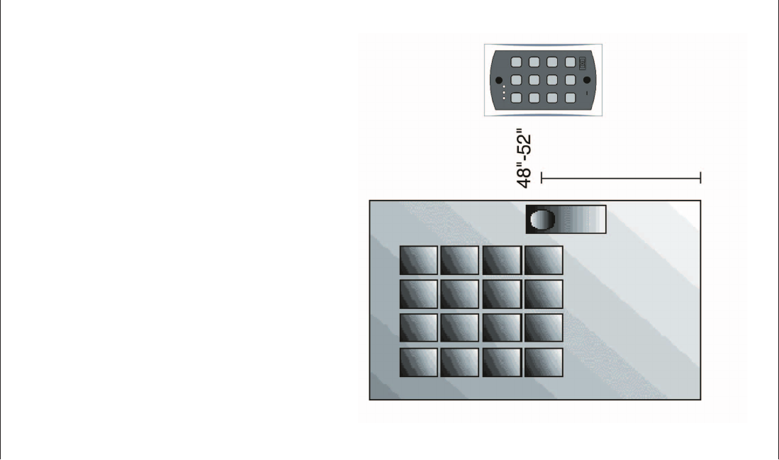
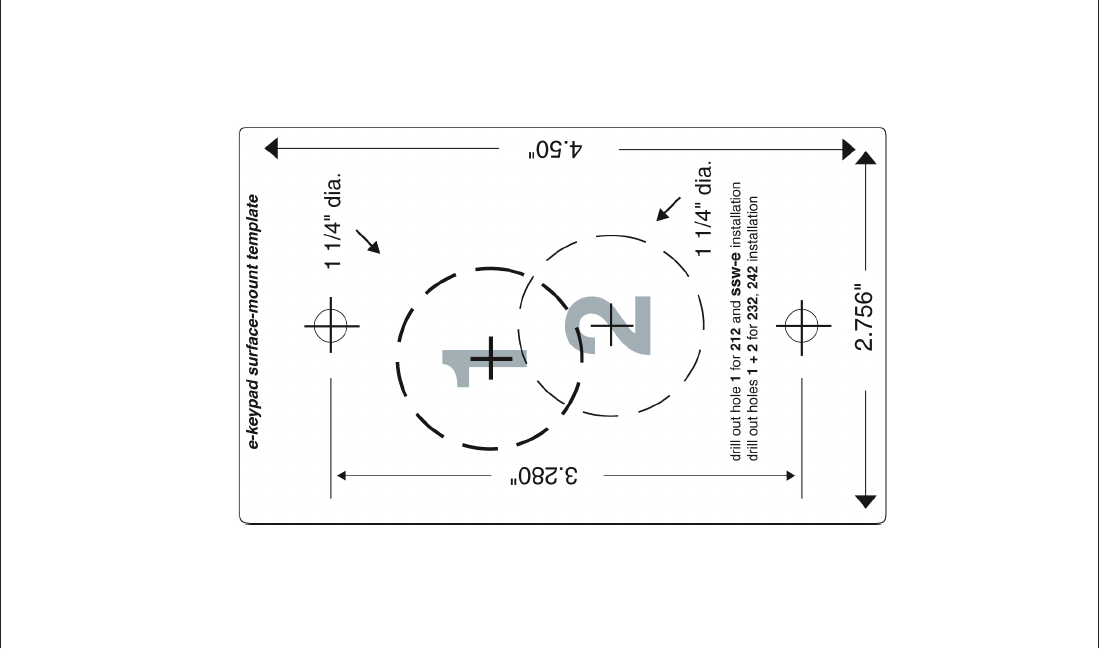
3. Mounting
The 212e Keypad is designed to be flush mounted using a standard
single-gang electrical box. In addition, it can be flush mounted di-
rectly to the wall surface by cutting a hole in the wall. In order to
properly size the mounting and wire access hole, use the installation
template on the last page of this manual and on the unit’s container.
Mounting height can vary depending on requirements. An appropri-
ate range is typically between 48 and 52 inches on center off the
floor.
For outdoor installations, use a weatherproof backbox and seal the
wire entry locations with silicone. In addition, use the anti-oxidant
grease pack for the wire harness connectors.
Figure 1 212e Mounting Height
IEI 212e Standalone Installation/Programming Manual
4 Document # 6104001, Rev. 1.0
4. Wiring
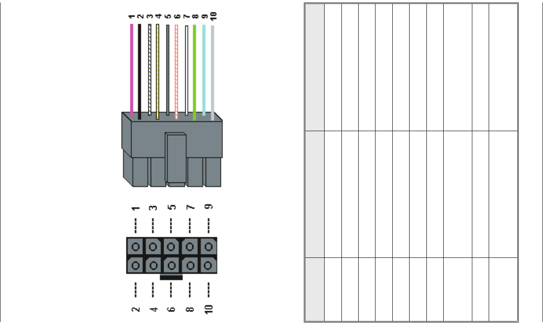
4.1 Wire Harness Configuration
Pin Wire Color Signal Name
1 Red V+
2 Black V-
3 White/Black Not Used
4 White/Yellow Not Used
5 Brown Remote Trigger (REX)
6 White/Orange Loop Common
7 White Not Used
8 Green Main Relay - Normally
Open
9 Blue Main Relay - Common
10 Gray Main Relay - Normally
Closed
Figure 2 212e Connector and Wire Harness
IEI 212e Standalone Installation/Programming Manual
Document # 6104001, Rev. 1.0 5
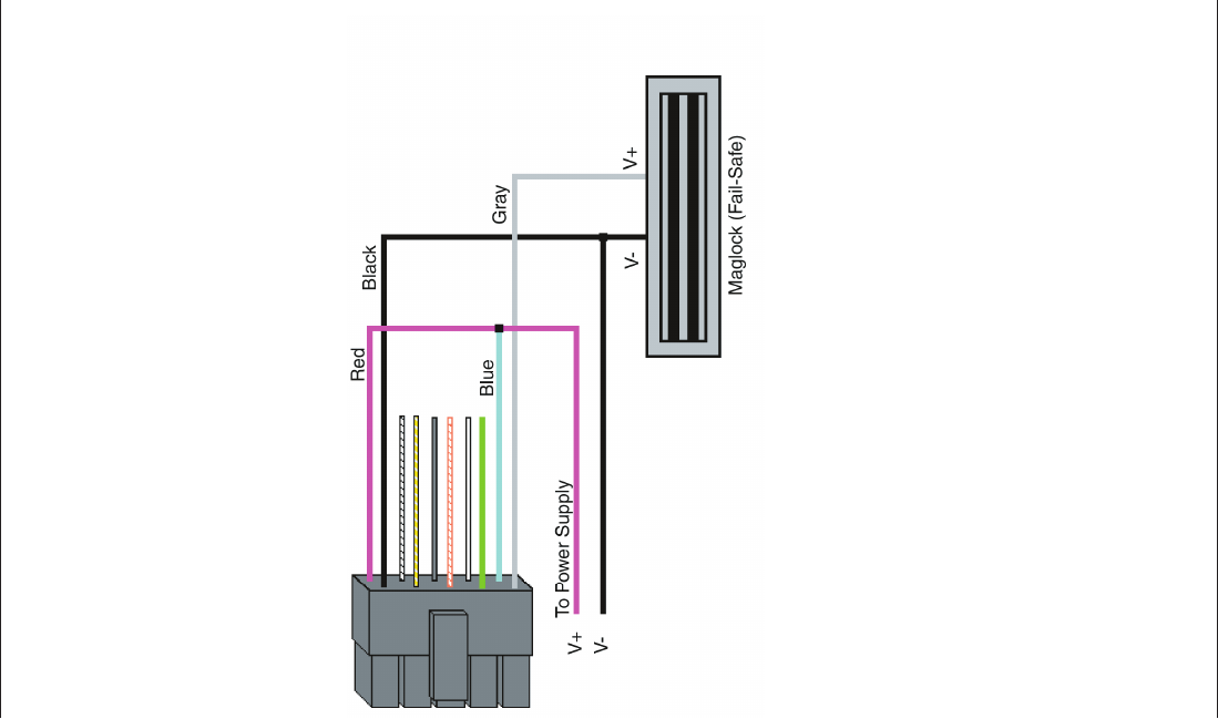
4.2 Wiring the 212e Keypad to a Maglock (Fail-
Safe)
Use the following steps to connect the 212e keypad to a Maglock
(Fail-Safe):
1. Connect the red wire (V+) to the blue wire (common), and
then connect them to the positive on the power supply.
2. Connect the gray wire (normally closed) to the positive on
the maglock.
3. Connect the black wire (V-) to the negative on the Maglock,
and then connect them to the negative on the power supply.
4.3 Wiring the 212e Keypad to an Electric
Strike (Fail-Secure)
Use the following steps to connect the 212e keypad to an electric
strike (fail-secure) (see Figure 4 for reference):
1. Connect the red wire (V+) to the blue wire (common), and
then connect them to the positive on the power supply.
2. Connect the green wire (normally open) to the positive on
the strike.
3. Connect the black wire (V-) to the negative on the strike, and
then connect them to the negative on the power supply.
Figure 3 Wiring 212e Keypad to a Maglock (Fail-Safe)
IEI 212e Standalone Installation/Programming Manual
6 Document # 6104001, Rev. 1.0
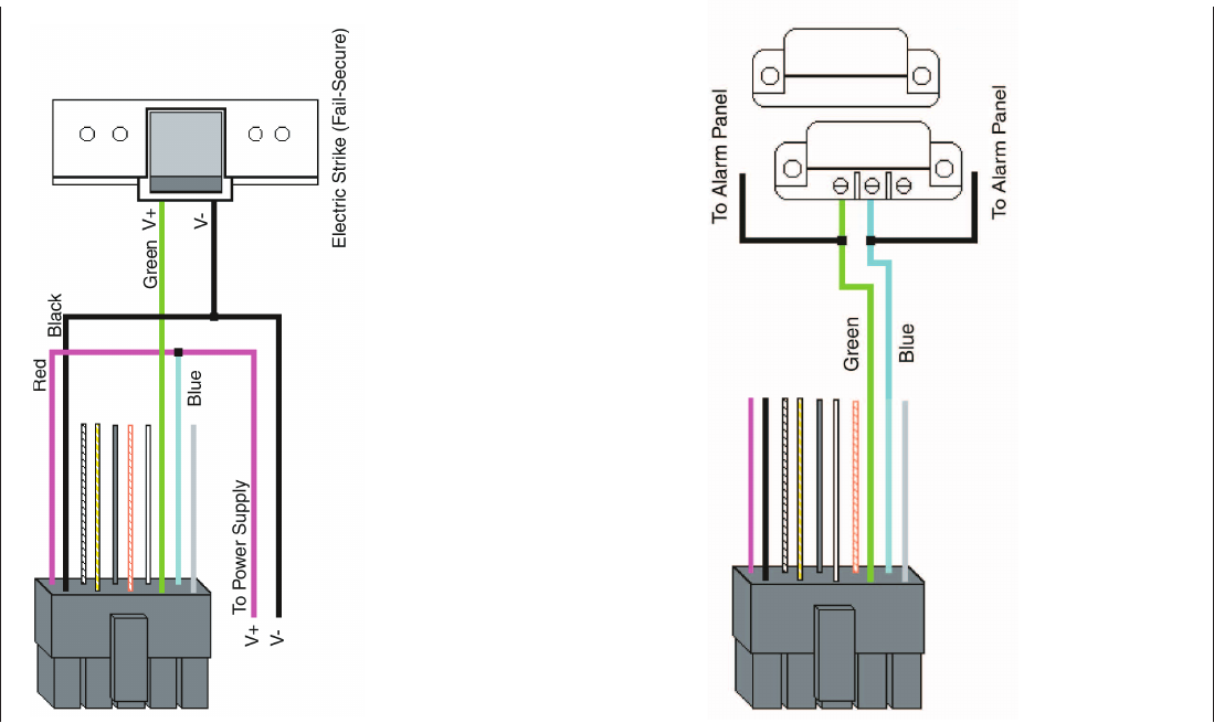
4.4 Shunting a Normally Closed Zone
Use the following steps to employ the 212e keypad to shunt a nor-
mally closed zone:
1. Connect the blue wire (common) to the common connection
on the door position switch.
2. Connect the green wire (normally open) to the normally
closed connection on the door position switch.
Figure 4 Wiring 212e Keypad to Electric Strike
Figure 5 Shunting a Normally Closed Zone
IEI 212e Standalone Installation/Programming Manual
Document # 6104001, Rev. 1.0 7
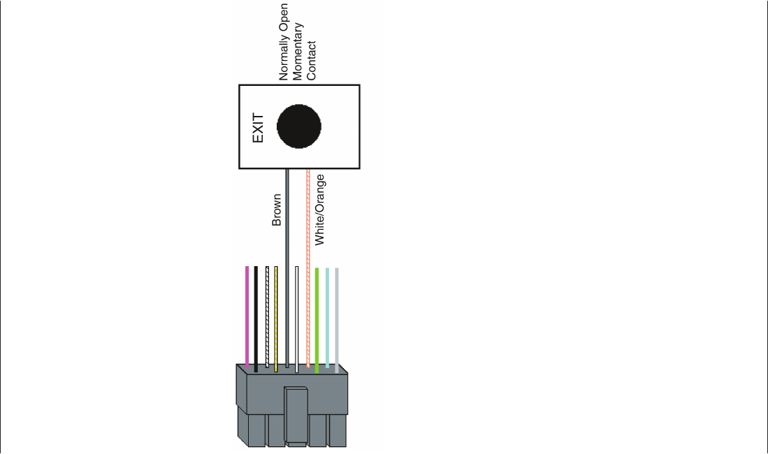
4.5 Wiring Remote Trigger as Request to Exit
(REX) Button
Use the following steps to connect the 212e keypad to a normally
open REX device and normally closed door switch:
1. Connect the brown wire (REX Input) to the normally open
connection the REX device.
2. Connect the white/orange wire (loop common) to the
common on the REX device.
Figure 6 Wiring a REX Button
IEI 212e Standalone Installation/Programming Manual
8 Document # 6104001, Rev. 1.0

5. Testing the Keypad
After installing the keypad, IEI recommends that you perform the
keypad self-test, to ensure that the keypad works properly.
1. To perform the self-test, with the unit powered up, press the
following keys on the keypad:
7890#123456*
•If all 12 keypresses are accepted, the keypad enters self-test
mode.
•The LEDs alternate green, yellow, and red followed by the
sounder beeping three times.
2. Verify that the master code works correctly. (The master code
accesses program mode and activates the main relay to verify
that the locking device is working.)
The default master code is 1234.
IEI 212e Standalone Installation/Programming Manual
Document # 6104001, Rev. 1.0 9
6. Programming
To program the 212e keypad, you must first enter program mode
by pressing 99 # Master Code *. The default Master Code is 1234.
6.1 Programming Main Relay Time
Command/Action Keys to Enter/Details
Command 11,
Set Main Relay Time
11 # time #0#**
(Time can be from 1-255 seconds.)
6.2 Programming Users
Command/Action Keys to Enter/Details
Master Code
User #1 is the master code; it can access
all commands in program mode. The default
code is 1234.
Supervisor Code
User #2, when programmed, is the
supervisor code. The supervisor can access
program mode, but is limited to adding and
deleting users, as well as enabling or
disabling users. The supervisor code can not
change, delete, or disable the master code
or supervisor code itself.
Add User user location # code * code *
Add User with
Specific Unlock Time
unlock time # user location # code *
code *
(This command is used to program a user
with a specific unlock. This user activates
the main relay.)
Add Toggle User 0 # user location # code * code *
(This user latches the main relay.)
Delete User user location # * *
IEI 212e Standalone Installation/Programming Manual
10 Document # 6104001, Rev. 1.0

Command/Action Keys to Enter/Details
Command 56.
Enable/Disable User 56 # enable/disable # user location # * *
Options: 1 = Disable
0 = Enable
The master code and supervisor code
cannot be disabled.
6.3 Programming Keypad Options
Command/Action Keys to Enter/Details
Command 30.
Enable/Disable
keypad options
30 # option # enable/disable # * *
Option Set/Clear
0 - audio keypress feedback 0=disabled, 1=ENABLED
1 - visual keypress feedback 0=disabled, 1=ENABLED
2 - auto-entry enable 0=DISABLED, 1=enabled
3 - error lockout 0=disabled, 1=ENABLED
6 - keypad illumination 0=disabled, 1=ENABLED
7 - keypad dimming 0=disabled, 1=ENABLED
Defaults are in bold.
Auto-entry
When auto-entry is enabled, users with
codes the same length as the master code
do not have to press the * key after entering
their code. If you have a code greater than
the master code, you can use Auto-Entry
Suspend. Just enter the # key prior to your
code followed by the * key. Example:
# 23456 * if the master code is four digits.
Error Lockout
When enabled, the keypad keeps track of
the number of consecutive invalid codes
entered, including attempts to access
program mode. When the threshold is
reached, the yellow LED turns on solid and
the keypad no longer responds to key
presses for the programmed time duration.
The count is reset by entering a valid code,
including entering program mode. The error
lockout threshold and duration is
programmed with command 32.
Keypad Illumination Keypad backlighting can be enabled or
disabled.
IEI 212e Standalone Installation/Programming Manual
Document # 6104001, Rev. 1.0 11

Command Action Keys to Enter/Details
Keypad Dimming
When enabled, the backlighting illumination
level decreases 15 seconds after the last
key press. When disabled, the backlighting
remains at full illumination at all times.
Command 32.
Change Keypad
Parameters
32 # parameter # value # * *
Parameter Value
2 - error lockout threshold 1 through 50 (defaults to 3)
3 - error lockout duration 1 through 255 (defaults to 10)
Command 40. Reset
defaults only.
40 # 00000 # 00000 # ** (master code, all
keypad options and parameters)
Command 46. Erase
Users and Reset
Default Settings.
46 # 00000 # 00000 # **
IEI 212e Standalone Installation/Programming Manual
12 Document # 6104001, Rev. 1.0

7. Troubleshooting
Refer to this section if the 212e keypad is not operating correctly as
described in this manual.
Problem Solution
The LEDs are slowly
cycling from right to left
and backlighting is off.
The 212e keypad is designed to monitor the input
voltage and this is an indication of under-voltage.
The under-voltage threshold is set to 8.5VDC,
and when the voltage drops below this limit, the
low voltage warning starts and backlighting is
turned off. To solve, raise the voltage to between
12-24V.
The LEDs are rapidly
cycling from left to right
and the keypad has
lost all operation.
The 212e keypad is designed to monitor the input
voltage, and this is an indication of over-voltage.
The over- voltage threshold is set to 36VDC, and
when the voltage rises above this limit, the
over-voltage warning starts and the keypad loses
all operation. To solve, lower the voltage to
between 12-24V.
The master code does
not work.
Perform the programming mode loopback and
reset the master code using the programming
command.
No LEDs are lit on the
keypad
Power is not reaching the keypad. Using a
voltmeter, confirm that there is voltage at the
keypad on the red and black wires. If there is no
voltage at the keypad, verify that there is voltage
at the power supply. If there is no voltage at the
power supply, call the manufacturer of the power
supply. If there is voltage at the power supply but
not at the keypad, verify there is no break in the
wires, then check continuity in the whole length of
the wire run. To verify that the keypad is working,
you can power the keypad with a 12-Volt Battery.
If the 212e Keypad still does not work after troubleshooting, please
call IEI’s technical support department at 1-800-343-9502 (outside
MA) or 1-800-733-9502 (inside MA). Operating hours are Monday
through Friday from 8:00 A.M. to 7:00 P.M. Eastern Standard Time.
IEI 212e Standalone Installation/Programming Manual
Document # 6104001, Rev. 1.0 13
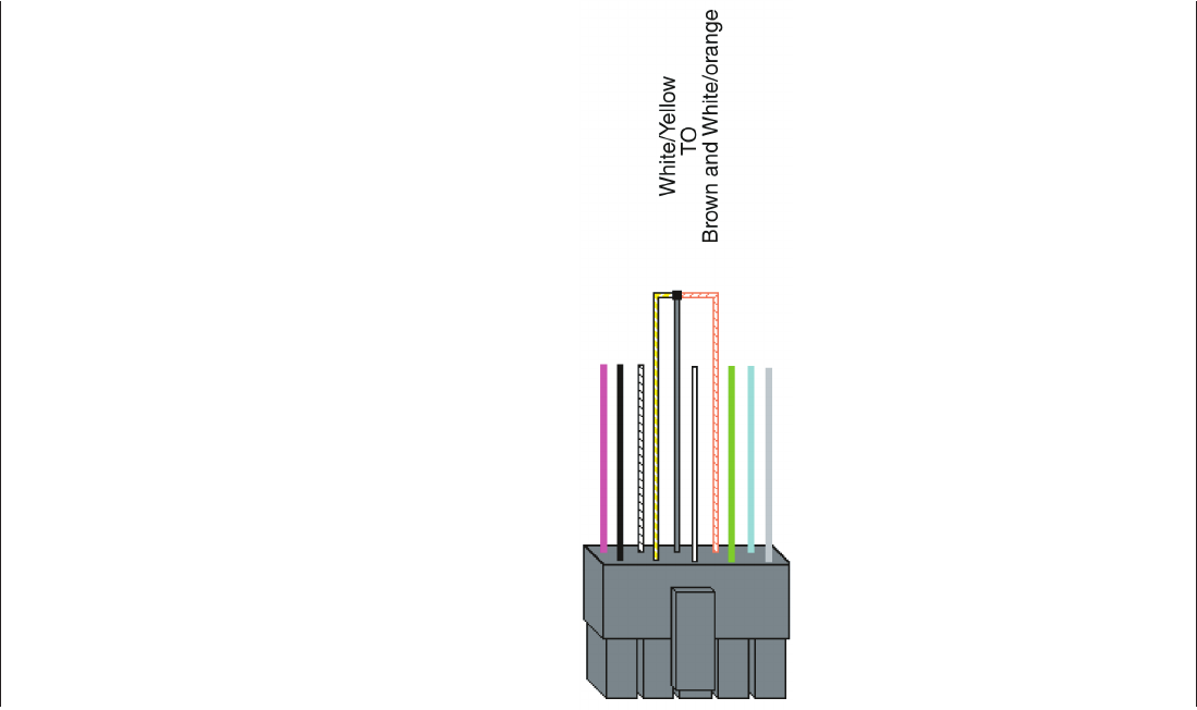
8. Programming Mode
Loopback
If the master code is either not working or forgotten, power
down the system, connect the wire harness as shown in Figure 9
below, and then power the system up again. Next, change your
master code and power down the system and restore the wire har-
ness to its original configuration and power the system back up.
First, disconnect power from the system. Next, connect the
White/Yellow wire to the Brown (REX) and White/Orange (Loop
Common) wire as shown in Figure 7. Finally, power up the key-
pad again.
Figure 7 Programming Mode Loopback Standalone
IEI 212e Standalone Installation/Programming Manual
14 Document # 6104001, Rev. 1.0

9. Warranty
International Electronics Incorporated (IEI) warrants its products to
be free from defects in material and workmanship, when they
have been installed in accordance with the manufacturer’s instruc-
tions, and have not been modified or tampered with. IEI does not
assume any responsibility for damage or injury to person or prop-
erty due to improper care, storage handling, abuse, misuse, normal
wear and tear, or an act of God.
IEI’s sole responsibility is limited to the repair (at IEI’s option) or
the replacement of the defective product or part when sent to
IEI’s facility (freight and insurance charges prepaid), after obtain-
ing IEI’s Return Merchandise Authorization. IEI will not be liable
to the purchaser or any one else for incidental or consequential
damages arising from any defect in, or malfunction of, its products.
This warranty shall expire five years after shipping date for Hub
Access Control System products. Except as stated above, IEI makes
no warranties, either expressed or implied, as to any matter what-
soever, including, without limitation to, the condition of its prod-
ucts, their merchantability, or fitness for any particular application.
IEI 212e Standalone Installation/Programming Manual
Document # 6104001, Rev. 1.0 15
IEI 212e Standalone Installation/Programming Manual
16 Document # 6104001, Rev. 1.0
