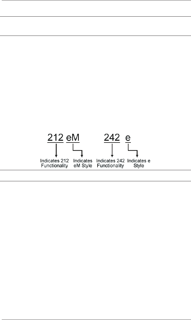
Linear 242Ez242Em Owners Manual Eseries.chp
Linear-212Em-Owners-Manual linear-212em-owners-manual
2014-07-19
: Linear Linear-242Ez242Em-Owners-Manual linear-242ez242em-owners-manual linear pdf
Open the PDF directly: View PDF ![]() .
.
Page Count: 28

e/eM Style Standalone
Keypad Installation/
Programming
Manual
This manual applies to these models: 212e, 212eM, 242e, and
242eM.
This equipment is designed to be installed and serviced by security
and lock industry professionals.
Contents
Section 1: Features and Product Description
Section 2: Specifications
Section 3: U.L. Requirements
Section 4: Mounting
Section 5: Wiring
Section 6: Testing the Keypad
Section 7: Programming
Section 8: Troubleshooting
Section 9: Programming Mode Loopback
Section 10: Warranty
Manual Revision Date: 12/10/04 Firmware Version: 1.0b
Put Service Company Contact Information Here:
Company Name:
Service Number:
Document # 6104401, Rev. 1.0, D1e 1

1. Features and Product
Description
1.1 Features
•Flush Mount
•Indoor and Outdoor Use
•Keypad Programmable
•Access Control Functionality*
•Individually Control up to 4 Devices*
•Illuminated Backlit Keys (e keypad only)
•Durable Metal Braille Keys (eM keypad only)
•Keypress Feedback via Built-In Sounder
•Bi-Color Red/Green LED Indicates Relay Status
•Yellow LED Indicates Program Mode
•120 Users
•Panic and Duress Options
•Single Use Codes
•Lockout Users
•Two-Man Rule Option
•10 to 30 Volt DC Operation
•12 to 24 Volt AC Operation
•2AmpMainRelay
•Remote Trigger Input (REX)
*242 only
1.1.1 Access Control Function (242 factory settings)
•RequesttoExitInput
•Door Monitoring Input
•Relay Outputs
-Lock Release
-Forced Door
-Propped Door
-Alarm Shunt
•Keypad Programmable
e/eM Style Standalone Installation/Programming Manual
2 Document # 6104401, Rev. 1.0, D1e
1.1.2 Output Functionality Options (242 field programma-
ble settings)
•Request To Exit and Door Monitor Inputs
•Four Independently Programmable Outputs
•All Outputs Assignable by Code
•Outputs Programmable For Latched or Timed Operation
•Keypad Programmable
1.2 Product Description and Naming Convention
IEI keypads and other standalone devices use an alpha-numeric
model number convention to identify functionality and style. The
numeric component identifies functionality. The alpha component
identifies style.
Examples:
1.2.1 Functionality
The 242 keypad features the most flexibility and options available
in a self-contained unit. It can perform access control functions,
and also its four relay outputs can be assigned independently for
timed operation or to latch. The 242 keypad can provide individual
control of up to four devices, and is perfect for controlling elec-
tronic locking devices, security systems, CCTV systems, automatic
operators, or machinery.
The 212 keypad features a single-relay output to control any device
requiring an on/off switch. The output is timed or latched and oper-
ated by a user’s PIN code. Additionally, the 212 keypad provides ba-
sic keyless entry by controlling a door locking device where security
is not an issue.
e/eM Style Standalone Installation/Programming Manual
Document # 6104401, Rev. 1.0, D1e 3

1.2.2 Style
e keypads: Flush mount backlit keypad.
eM keypads: Flush mount durable metal keypad.
All keypads: Designed for both indoor and outdoor flush mount
applications. The electronics for each keypad are conformal coated
in the manufacturing process in order to provide this level of appli-
cation flexibility. Installation is easy. All keypads mount to any
standard single-gang electrical box or directly to any wall.
NOTE: This manual covers both 212 and 242 models. All fea-
tures referring to the additional relays and outputs are
available only on the 242 model.
e/eM Style Standalone Installation/Programming Manual
4 Document # 6104401, Rev. 1.0, D1e

2. Specifications
Parameter Range/Description
Voltage 10-30 VDC, 12-24 VAC (Auto-Adjusting)
Current
e:
75mA@10VDC,
100mA@30VDC,
125mA@12VAC, and
200mA@24VAC
eM:
46mA@10VDC; 49mA@12VAC;
60mA@24VAC; 68mA@30VDC
Add 20 mA for each energized aux relay
Environment Indoor and Outdoor
Temperature Tolerance -20 °F to 130 °F (-28 °C to 54 °C)
Dimensions 4.5" H x 2.75" W x 0.60" D
Main Relay (Form C) Contact Rating: 2A @ 30VAC/DC
Aux Relay (Form C) Contact Rating: 1A @ 24V AC/DC
REX Input Normally Open Dry Contact
Door Position Input Normally Closed Dry Contact
LEDs Bi-Color Red/Green Yellow
Default Settings
Parameter Default Setting
Master Code 1234
Lock Output Relay 1 (Main Relay) (212 and 242)
Alarm Shunt Relay 2 (242)
Propped Door Relay 3 (242)
Forced Door Relay 4 (242)
Audio Alerts Not Assigned (212 and 242)
REX Triggers Lock Output
REX Operation Always Triggers (regardless of
Door Loop)
Error Lockout Enabled
Error Lockout Threshold 3 Attempts
Error Lockout Duration 10 Seconds
Lock Output Time 5 Seconds
Propped Door Time 30 Seconds
Forced Door Time 10 Seconds
Visual Keypress Feedback Enabled
Audio Keypress Feedback Enabled
Auto-Entry Disabled
User Lockout Enabled
e/eM Style Standalone Installation/Programming Manual
Document # 6104401, Rev. 1.0, D1e 5

3. U.L. Requirements
NOTE:Thissectionappliestothe 212e and 242e keypads only.
The 212eM and 242eM keypads are not U.L. Listed.
The 212e/242e keypad is a U.L. Listed access control unit. This sec-
tion contains information regarding all the requirements necessary
to meet U.L. requirements.
This system must be installed in accordance with the National Elec-
trical code (NFPA70), local codes, and the authorities having juris-
diction. In addition, all wires and cables used must be stranded
andshieldedU.L.Listedand/orrecognizedwire.
All interconnecting devices (that is, door contacts, REX, locking de-
vices, etc.) must be U.L. Listed. A U.L. Listed access control power
limited power supply must be used to power the keypad.
A minimum of three user codes must be programmed into the key-
pad for controlling access.
3.1 Tamper Requirements
To meet U.L. requirements, a U.L. Listed tamper switch must be in-
stalled in the single gang box used for mounting the keypad. The
tamper switch must activate if the keypad is removed from the box
and must disconnect power from the lock. The lock must be a fail-
secure device, meaning the lock remains locked when power is re-
moved. In addition, once the tamper device is activated, it must be
configured so that it can only be reset from within the protected
area. Only a Sentrol 3012 or Sentrol 3025T tamper switch can be
used. The diagrams on the next page show the suggested mount-
ing location for each device.
e/eM Style Standalone Installation/Programming Manual
6 Document # 6104401, Rev. 1.0, D1e
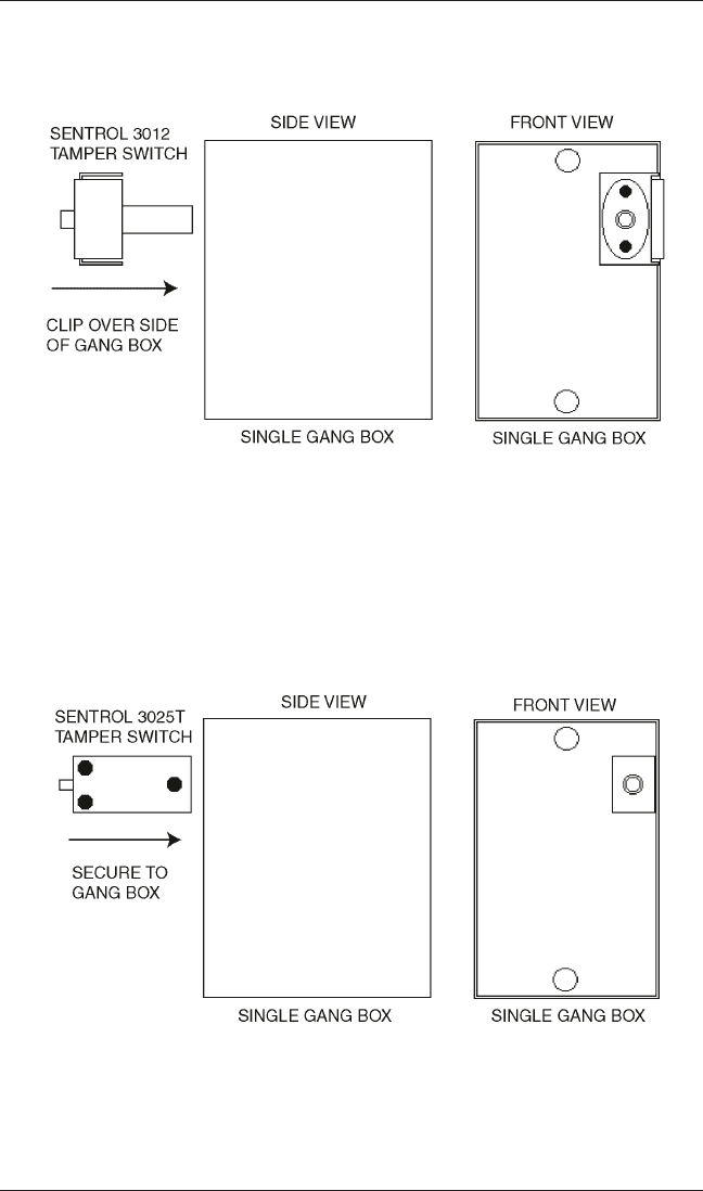
Figure 1 Mounting a Sentrol 3012 Tamper Switch
Figure 2 Mounting a Sentrol 3025T Tamper Switch
e/eM Style Standalone Installation/Programming Manual
Document # 6104401, Rev. 1.0, D1e 7
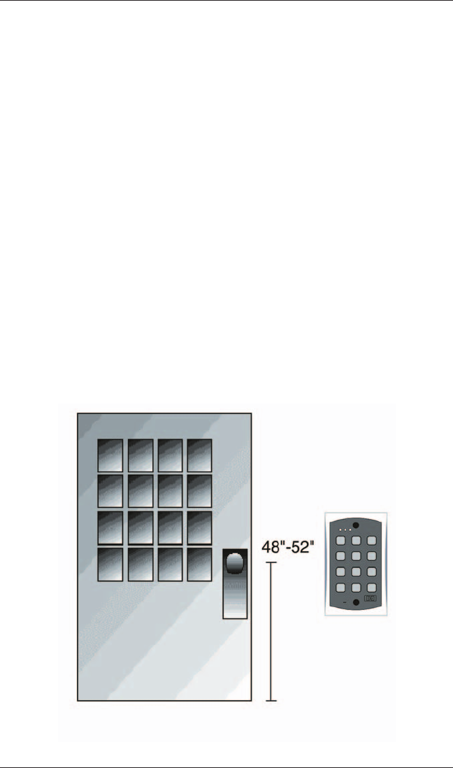
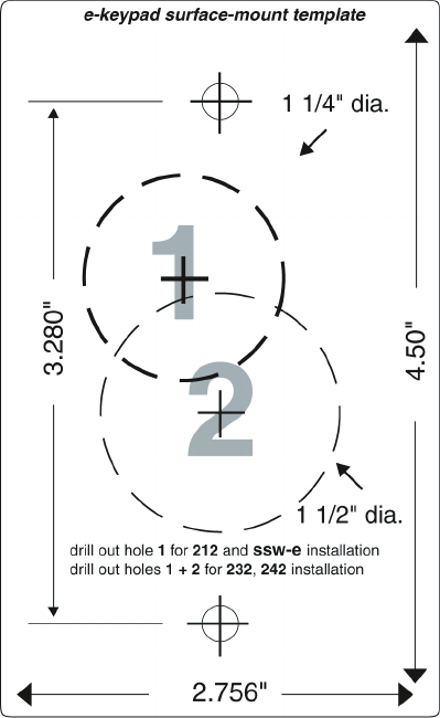
4. Mounting
The keypad is designed to be flush mounted using a standard sin-
gle-gang electrical box. In addition, it can be flush mounted di-
rectly to the wall surface by cutting a hole in the wall. To properly
size the mounting and wire access hole, use the installation tem-
plate on the last page in this manual and on the unit’s container.
Mounting height can vary depending on requirements. An appro-
priate range is typically between 48 and 52 inches on center off the
floor.
For outdoor installations, use a weatherproof backbox and seal the
wire entry locations with silicone and provide a drain hole. In addi-
tion,usetheanti-oxidantgreasepackforthewireharnessconnec-
tors.
Figure 3 Keypad Mounting Height
e/eM Style Standalone Installation/Programming Manual
8 Document # 6104401, Rev. 1.0, D1e

5. Wiring
5.1 Wire Harness Configuration
Pin Wire Color Signal Name
1Red V+
2Black V-
3 White/Black Not Used
4 White/Yellow Not Used
5 Brown Remote Trigger (REX)
6 White/Orange Loop Common
7 White Door Loop Monitor
8 Green Main Relay - Normally
Open
9 Blue Main Relay - Common
10 Gray Main Relay - Normally
Closed
Figure 4 Keypad Connector and Wire Harness
NOTE: For wiring the accessory relay board, see sections 5.6 and 5.7.
e/eM Style Standalone Installation/Programming Manual
Document # 6104401, Rev. 1.0, D1e 9
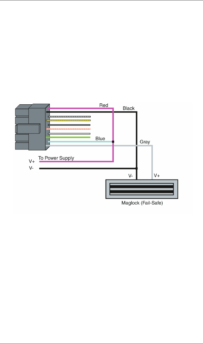
5.2 Wiring the Keypad to a Maglock (Fail-Safe)
Use the following steps to connect the keypad to a Maglock (Fail-
Safe):
1. Connect the red wire (V+) to the blue wire (common), and
then connect them to the positive on the power supply.
2. Connect the gray wire (normally closed) to the positive on
the maglock.
3. Connect the black wire (V-) to the negative on the Maglock,
and then connect them to the negative on the power supply.
5.3 Wiring the Keypad to an Electric Strike
(Fail-Secure)
Use the following steps to connect the keypad to an electric strike
(fail-secure) (seeFigure6forreference):
1. Connect the red wire (V+) to the blue wire (common), and
then connect them to the positive on the power supply.
2. Connect the green wire (normally open) to the positive on
the strike.
3. Connect the black wire (V-) to the negative on the strike, and
then connect them to the negative on the power supply.
Figure 5 Wiring the Keypad to a Maglock (Fail-Safe)
e/eM Style Standalone Installation/Programming Manual
10 Document # 6104401, Rev. 1.0, D1e
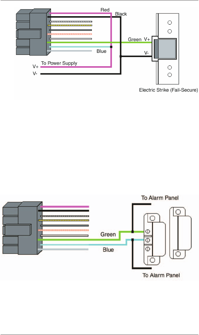
5.4 Shunting a Normally Closed Zone
Use the following steps to employ the keypad to shunt a normally
closed zone:
1. Connect the blue wire (common) to the common connection
on the door position switch.
2. Connect the green wire (normally open) to the normally
closed connection on the door position switch.
Figure 6 Wiring the Keypad to Electric Strike
Figure 7 Shunting a Normally Closed Zone
e/eM Style Standalone Installation/Programming Manual
Document # 6104401, Rev. 1.0, D1e 11
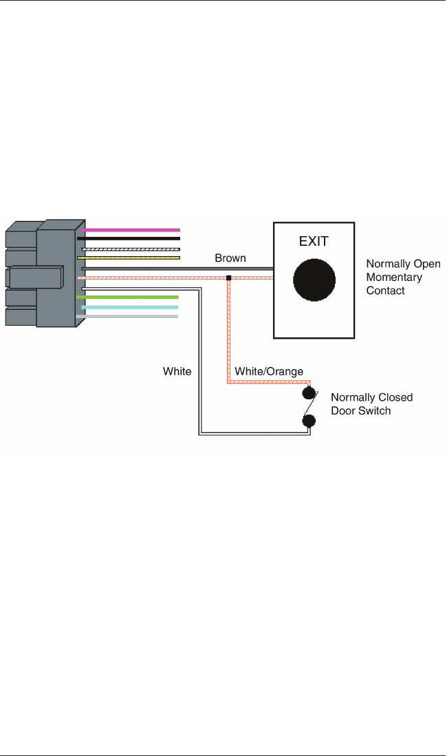
5.5 Wiring Remote Trigger as Request to Exit
(REX) Button and Door Contacts
Use the following steps to connect the keypad to a normally open
REX device and normally closed door switch:
1. Connect the brown wire (REX Input) to the normally open
connection the REX device.
2. Connect the white/orange (loop common) to the common on
theREXdeviceandthecommonthedoorswitch.
3. Connect the white wire (door loop) to the normally closed
connection on the door switch.
NOTE: By default, the REX function operates the virtual lock out-
put only, but this can be changed using command 49. In addition,
the door loop does not need to be closed for the REX function to
operate, by default, but setting option 8 to 0 under command 30
programs the REX function to operate only when the door loop is
closed. This prevents the REX from re-triggering when the door is
open.
Figure 8 Wiring a REX Button and Door Contacts
e/eM Style Standalone Installation/Programming Manual
12 Document # 6104401, Rev. 1.0, D1e
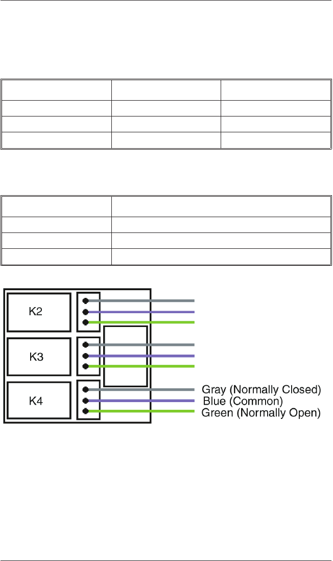
5.6 Wiring an Accessory Relay Board (242 only)
Theaccessoryrelayboardcontainsphysicaloutputs2,3,and4
shown in the table below.
Physical Output Relay Connector
2K2P1
3K3P2
4K4P3
Use the wire harnesses supplied with the relay board to connect to
therelays.Thewirecolorsareshowninthetablebelow.
Wire Color Relay Connection
Gray Normally Closed
Blue Common
Green Normally Open
5.7 Wiring an Integrated Access Control
System Using the Accessory Relay Board
Physicaloutputs2,3,and4aredefaulted to the alarm shunt,
propped door, and forced door virtual outputs, respectively. Use
the following steps to wire the alarm shunt, propped door alarm,
and forced door alarm.
Figure 9 Wiring an Accessory Relay Board
e/eM Style Standalone Installation/Programming Manual
Document # 6104401, Rev. 1.0, D1e 13
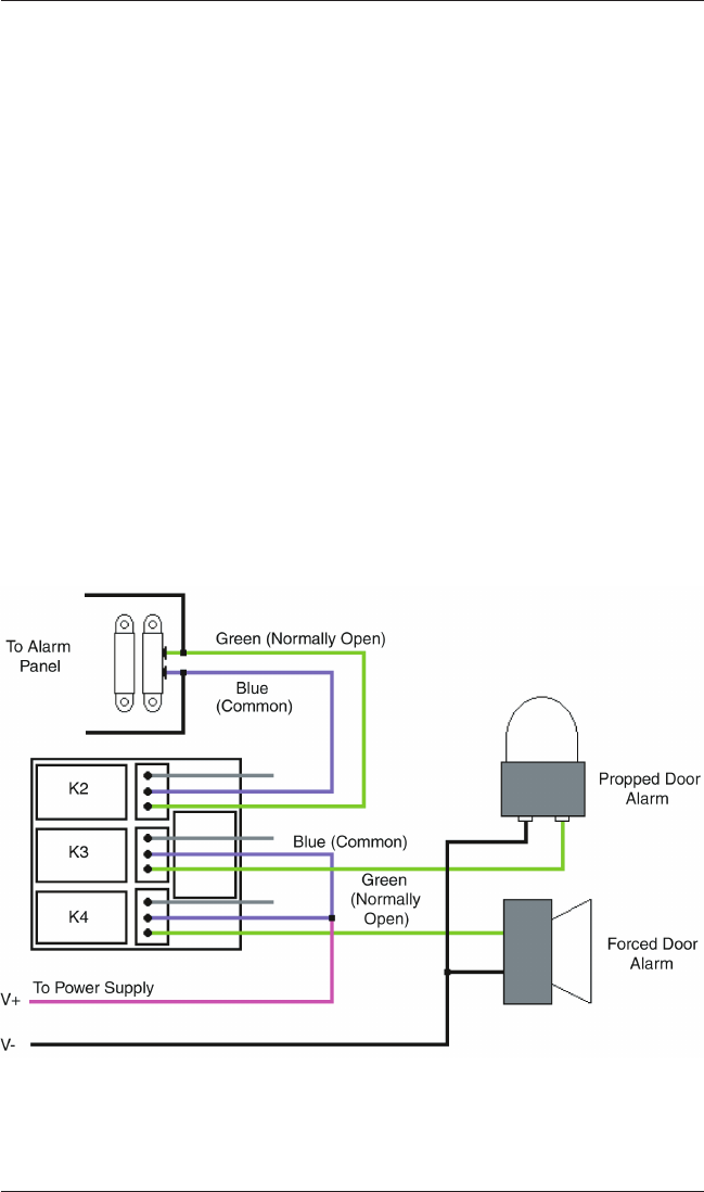
NOTE: You MUST wire a normally closed door switch, as shown
in Figure 6, for these functions to work properly.
1. (Wiring the alarm shunt) Using P1 (K2), connect the blue
wire (common) to common on the door switch. Connect the
green wire (normally open) to the normally closed contact on
the door switch.
2. (Wiring the propped door alarm) Using P2 (K3), connect the
green wire (normally open) to the positive on the alarm
device.Connectthebluewire(common)tothepositiveon
thepowersupply.Connectthenegativeonthealarmdevice
to the negative on the power supply.
3. (Wiring the forced door alarm)UsingP3(K4),connectthe
green wire (normally open) to the positive on the alarm
device.Connectthebluewire(common)tothepositiveon
thepowersupply.Connectthenegativeonthealarmdevice
to the negative on the power supply.
Figure 10 Wiring an Integrated Accessory Relay Board
e/eM Style Standalone Installation/Programming Manual
14 Document # 6104401, Rev. 1.0, D1e
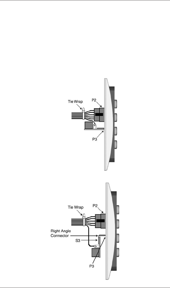
Figure 11 Plugging on Relay Board - Option 1
There are two options for plugging the relay board onto the key-
pad, depending on the installation. For flush mount applications,
plug the relay board onto P3 horizontally, as shown in Option 1 be-
low. If the keypad is mounted using a surface mount backbox, use
the right angle connector included in the backbox. First insert the
right angle connector into S3 on the relay board; then plug the con-
nector onto P3 on the keypad. This is shown in Option 2 below.
Use the included tie wrap to bundle all the wires together from the
keypad wire harness and relay board.
NOTE: The IEI backbox is not U.L. listed
Figure 12 Plugging on Relay Board - Option 2
e/eM Style Standalone Installation/Programming Manual
Document # 6104401, Rev. 1.0, D1e 15

6. Testing the Keypad
After installing the keypad, IEI recommends that you perform the
keypad self-test once a year, to ensure that the keypad works prop-
erly.
1. To perform the self-test, with the unit powered up, press the
following keys on the keypad:
7890#123456*
•If all 12 keypresses are accepted, the keypad enters self-test
mode.
•The LEDs alternate green, yellow, and red followed by the
sounder beeping three times.
2. Verify that the master code works correctly. (The master code
accesses program mode and activates the main relay to verify
that the locking device is working.)
The default master code is 1234.
(If the default is not working, refer to section 9.)
e/eM Style Standalone Installation/Programming Manual
16 Document # 6104401, Rev. 1.0, D1e

7. Programming
To program the keypad, you must first enter program mode by
pressing 99 # Master Code *. The default Master Code is 1234.
NOTE: If auto-entry is enabled, the * (asterisk) key is not used to
enter Program mode. To change the Master Code, enter:
1 # new Master Code * new Master Code *
(To exit Program Mode, press *.)
7.1 Programming Order
To ensure that the keypad is programmed properly in the initial
installation, program the keypad in the following order:
•Step 1: Assigning Virtual Outputs to Physical Outputs
•Step 2: Programming Output Time Durations
•Step 3: Programming Users
•Step 4: Programming Keypad Options
7.2 Assigning Virtual Outputs to Physical
Outputs
ThekeypadisequippedwithelevenVirtualOutputsandsixPhysi-
cal Outputs. Virtual Outputs are functions that you can assign to op-
erate any Physical Output. Physical Outputs include the main relay,
the three relays on the aux relay board, and the two audio alerts.
The 242 model has six physical outputs (four relays and two audio
alerts). The 212 model has three physical outputs (a main relay
and two audio alerts).
•Using command 10, you can assign any Virtual Output to
any Physical Output or disable a Physical Output.
•Each Physical Output can only have one Virtual Output
assigned to it.
e/eM Style Standalone Installation/Programming Manual
Document # 6104401, Rev. 1.0, D1e 17

Command/Action Keys to Enter/Details
Command 10.
Assign Virtual
Outputs to Physical
Outputs
10#virtualoutput#physicaloutput#*
*
Virtual Output List Physical Output List
0 - No mapping 1 - Relay 1 (Main Relay)
(physical output unused)
1-Lock 2-Relay2(K2)
2 - Alarm Shunt 3 - Relay 3 (K3)
3 - Propped Door 4 - Relay 4 (K4)
4-ForcedDoor 9-AudioAlert#1
5 - OUT2 10 - Audio Alert #2
6-OUT3
7-OUT4
8-OUT5
13 - Duress
14 - Panic
15 - Keypad Active
* Audio alerts are described in section 7.2.2.
Defaults—The
keypad comes
programmed with
the following default
output assignments:
The Lock Output is assigned to Relay 1, the
Alarm Shunt Output to Relay 2, the Propped
Door Output to Relay 3, and the Forced
Door Output to Relay 4.
7.2.1 Virtual Outputs
Virtual Output Description/Details
Lock This output is used for your locking device.
Alarm Shunt
This is used to shunt out an existing alarm
panel. It activates with the lock output and
de-energizes one second after the lock time
expires.
Propped Door
This output activates after entering a valid
user code only if the door position switch is
left open longer than the programmed
propped door time.
e/eM Style Standalone Installation/Programming Manual
18 Document # 6104401, Rev. 1.0, D1e

Virtual Output Description/Details
Forced Door
This output activates if the door position
switch is opened without entering a valid
user code.
OUT2, OUT3, OUT4,
OUT5
These four independently controlled outputs
are activated by user codes programmed to
activate multiple outputs and the REX
function. See programming commands 59
and 49 in the Programming section.
Duress
The duress output is activated when a
duress user enters their code. See Duress
User in the Programming section.
Panic
Panicisactivatedbypressingthe*and #
keys at the same time. This is used in case
of emergency to activate an auxiliary device
andshouldnotbeusedtogainaccess.
Keypad Active
The Keypad Active output is activated when
any key is pressed. Do not use this output
to gain access.
7.2.2 Audio Alerts
Audio Alerts are produced by the local sounder on the keypad
and can be used as a local propped door alarm or forced door
alarm to free up the other relays for other functions.
•Alert #1 is a constant quick beep (¼ second on and ¼ sec-
ond off).
•Alert #2 is a short beep (100 ms) every two seconds.
•Alert #1 takes priority over Alert #2.
7.2.3 Programming REX Outputs
For wiring information, see section 5.5.
49#outputlist#0#**
(Use this command to program which outputs the REX operates.
1=LOCK,2=OUT2,3=OUT3,
4=OUT4,and5=OUT4.)
e/eM Style Standalone Installation/Programming Manual
Document # 6104401, Rev. 1.0, D1e 19

7.3 Programming Output Time Durations
Command/Action Keys to Enter/Details
Command 11. Set
LOCK Time Duration
11 # time # 0 # * * (time = 1 to 255
seconds)
Command 12. Set
OUT2 Time Duration 12 # ttt # pre # * *
Command 13. Set
OUT3 Time Duration 13 # ttt # pre # * *
Command 14. Set
OUT4 Time Duration 14 # ttt # pre # * *
Command 15. Set
OUT5 Time Duration 15 # ttt # pre # **
Options:
ttt
(Example:)
number of time units to operate OUTn when
valid PIN entered (1 through 255)
12#1#10#(for ten seconds)
pre
(Example:)
number of seconds in each time unit
(prescaler)
12#15#1#(for fifteen seconds)
Command 44. Set
Propped Door Time 44 # time # 0 # * *
Options:
time
Propped Door Time - rounded down to
nearest 10’s of seconds; entered as 00, 10
through 990, defaults to 30 seconds;
entering a time of zero disables the propped
door function
Command 45. Set
Forced Door Time 45 # time # 0 # * *
Options:
time
Forced Door Time - rounded down to
nearest 10’s of seconds; entered as 00, 10
through 990, defaults to 10 seconds;
entering a time of zero latches the virtual
forced door that can be cleared with any
valid PIN or by entering program mode
e/eM Style Standalone Installation/Programming Manual
20 Document # 6104401, Rev. 1.0, D1e

Command/Action Keys to Enter/Details
Command 32.
Change Keypad
Parameters
32 # parameter # values # * *
Parameter Value
0 - duress output duration 1 through 255 (defaults to 5)
1 - panic output duration 1 through 255 (defaults to 5)
2 - error lockout threshold 1 through 50 (defaults to 3)
3 - error lockout duration 1 through 255 (defaults to 10)
7.4 Programming Users
Command/Action Keys to Enter/Details
Master Code
User #1 is the master code; it can access all
commands in program mode. The default
code is 1234. The master code can be
programmed with command 50 or command
60 as a standard user only.
Supervisor Code
User #2, when programmed, is the supervisor
code. The supervisor can access program
mode, but is limited to adding and deleting
users, as well as enabling or disabling users.
The supervisor code can not change, delete,
or disable the master code or supervisor code
itself.
Add Standard User
(short version) user location # code * code *
Add User with
Specific Unlock Time
unlock time # user location # code * code *
(This command is used to program a user
with a specific unlock. This user activates the
virtual lock output.)
Delete User user location # * *
e/eM Style Standalone Installation/Programming Manual
Document # 6104401, Rev. 1.0, D1e 21

Command/Action Keys to Enter/Details
Command 60.
Add/Modify Enhanced
User
60 # type # location # code * code *
(codes can be from 1 to 10 digits in length)
User Types
0 - Toggle User
1-StandardUser
3 - Lockout User
5 - Single Use Code
7 - Emergency User
8-DuressUser
9 - Two-Part User Type A
10 - Two-Part User Type B
Toggle User A toggle user latches the virtual lock output.
Standard User Activates the virtual lock output using the lock
duration programmed with command 11.
Lockout User
This user type locks out users in user locations
higher than the lockout user when the lockout
user code is entered. For example, if the lockout
user is programmed for user 20, any user in
location 21 to 120 is locked out and their codes
no longer work to gain access. A lockout is
removed by entering the same lockout code. If
another lockout code in another user location is
entered, the lockout user location level is set to
the new lockout user location. The master code
and emergency users can not be locked out.
The current lockout is cleared when program
mode is entered. “Lockout activated” is indicated
by two double beeps. “Lockout canceled” is
indicated by one double beep.
“Access denied due to lockout” is indicated by 1
long beep followed by 3 short beeps.
“User lockout” can be enabled or disabled with
command 30.
Single Use Code
This code can only be entered once to gain
access using the lock virtual output. Once used,
this code is no longer active. A single use code
can be verified by entering 5 # code *. If the
code is a single use code, the green LED flashes
for ½ a second. An “invalid code” is indicated by
3 quick beeps.
Emergency User This user type is a standard user that can not be
locked out by a lockout user.
e/eM Style Standalone Installation/Programming Manual
22 Document # 6104401, Rev. 1.0, D1e

Command/Action Keys to Enter/Details
Duress User
Entering a duress code activates the lock and
duress virtual outputs. This allows you to trigger
another device silently, such as an alarm, and
still gain access in case of an emergency.
Two-Part Users A
and B
When the two-part user option is enabled, two
codes are required to gain access. A “Two-Part
Type A” and “Two-Part Type B” user must enter
their code (not necessarily in that order). After
the first code is entered, the LED alternates
between red and green, indicating another code
is required. The second code must be entered
within 15 seconds of the first code. When two
codes of the same type are entered, a type
mismatch is indicated by 5 beeps. When
Two-Part User is disabled, all Type A and B user
codes are converted to standard user codes.
Two-Part users activate the virtual lock output.
Two-Part Users can be enabled or disabled with
command 30.
Command 56.
Enable/Disable User 56 # enable/disable # user location # * *
Options: 1 = Disable
0 = Enable
The master code and supervisor code
cannot be disabled.
Command 59.
Program users to
operate virtual outputs
OUT2, OUT3, OUT4,
and OUT5 as well as
the virtual lock output.
59 # output list # location # code * code *
(Use this command to operate multiple outputs
and the virtual lock output using a single code.
This is useful when you want to operate a
separate device while unlocking the door and
still use some of the access control features
such as alarm shunt, propped door, forced door
and REX.
The output list is specified by entering the
output(s) you want the code to operate.
1 = LOCK, 2 = OUT2, 3 = OUT3,
4=OUT4,and5=OUT5.
e/eM Style Standalone Installation/Programming Manual
Document # 6104401, Rev. 1.0, D1e 23

7.5 Programming Keypad Options
Command/Action Keys to Enter/Details
Command 30.
Enable/Disable keypad
options
30 # option # enable/disable # * *
Option Set/Clear
0 - audio keypress feedback 0=disabled, 1=ENABLED
1 - visual keypress feedback 0=disabled, 1=ENABLED
2 - auto-entry enable 0=DISABLED, 1=enabled
3 - error lockout 0=disabled, 1=ENABLED
4 - user lockout 0=disabled, 1=ENABLED
5 - two-part users 0=disabled, 1=ENABLED
6 - keypad illumination 0=disabled, 1=ENABLED
7 - keypad dimming 0=disabled, 1=ENABLED
8 - REX operation 0=only when door loop closed
1=always
Defaults are in bold. Options 6 and 7 available only in e keypads.
Auto-entry
When auto-entry is enabled, users with codes
the same length as the master code do not have
to press the * key after entering their code. If
you have a code greater than the master code,
you can use Auto-Entry Suspend. Just enter the
# key prior to your code followed by the * key.
Example:
# 23456 * if the master code is four digits.
Error Lockout
When enabled, the keypad keeps track of the
number of consecutive invalid codes entered,
including attempts to access program mode.
When the threshold is reached, the yellow LED
turns on solid and the keypad no longer
responds to key presses for the programmed
time duration. The count is reset by entering a
valid code, including entering program mode.
The error lockout threshold and duration is
programmed with command 32.
Keypad Illumination Keypad backlighting can be enabled or disabled.
Keypad Dimming
When enabled, the backlighting illumination level
decreases 15 seconds after the last key press.
When disabled, the backlighting remains at full
illumination at all times.
Command 40. Reset
defaults only.
40 # 00000 # 00000 # ** (master code, all
keypad options and parameters)
Command 46. Erase
Users and Reset
Default Settings.
46 # 00000 # 00000 # **
e/eM Style Standalone Installation/Programming Manual
24 Document # 6104401, Rev. 1.0, D1e

8. Troubleshooting
Refer to this section if the keypad is not operating correctly as de-
scribed in this manual.
Problem Solution
The LEDs are slowly
cycling from right to
left and backlighting is
off.
The keypad is designed to monitor the input
voltage and this is an indication of under-voltage.
The under-voltage threshold is set to 8.5VDC,
and when the voltage drops below this limit, the
low voltage warning starts and backlighting is
turned off. To solve, raise the voltage to between
12-24V.
The LEDs are rapidly
cycling from left to
right and the keypad
has lost all operation.
The keypad is designed to monitor the input
voltage, and this is an indication of over-voltage.
The over- voltage threshold is set to 36VDC, and
when the voltage rises above this limit, the
over-voltage warning starts and the keypad loses
all operation. To solve, lower the voltage to
between 12-24V.
Themastercodedoes
not work.
Perform the programming mode loopback and
reset the master code using the programming
command.
No LEDs are lit on the
keypad
Power is not reaching the keypad. Using a
voltmeter, confirm that there is voltage at the
keypad on the red and black wires. If there is no
voltage at the keypad, verify that there is voltage
at the power supply. If there is no voltage at the
power supply, call the manufacturer of the power
supply. If there is voltage at the power supply
but not at the keypad, verify there is no break in
the wires, then check continuity in the whole
length of the wire run. To verify that the keypad
is working, you can power the keypad with a
12-Volt Battery.
If the keypad still does not work after troubleshooting, please call
IEI’s technical support department at 1-800-343-9502 (outside MA)
or 1-800-733-9502 (inside MA). Operating hours are Monday
through Friday from 8:00 A.M. to 7:00 P.M. Eastern Standard Time.
e/eM Style Standalone Installation/Programming Manual
Document # 6104401, Rev. 1.0, D1e 25
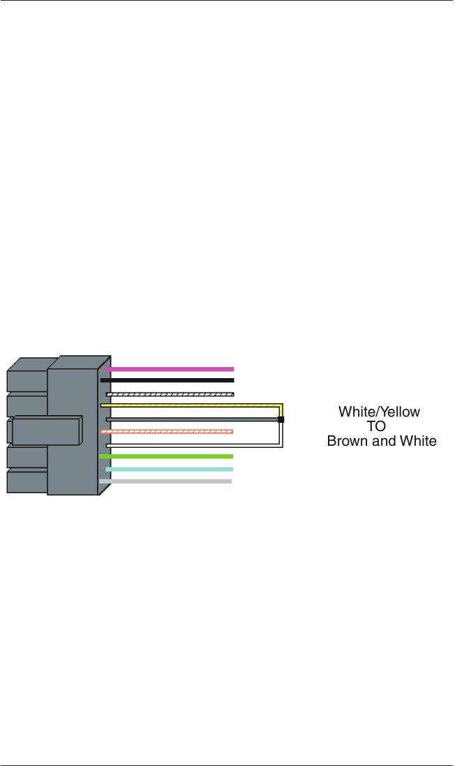
9. Programming Mode
Loopback
If the Master Code is either not working or forgotten, power
down the system, connect the wire harness as shown in Figure 13
below, and then power the system up again. Next, change your
Master Code and power down the system and restore the wire
harness to its original configuration and power the system back
up.
First, disconnect power from the system. Next, connect the
White/Yellow wire to the Brown (REX) wire and the White (Door
Loop) wire as shown in Figure 13, and then power up the keypad
again.
Figure 13 Programming Mode Loopback Standalone
e/eM Style Standalone Installation/Programming Manual
26 Document # 6104401, Rev. 1.0, D1e
10. Warranty
International Electronics Inc. (IEI) warrants its products to be free
from defects in material and workmanship when they have been
installed in accordance with the manufacturer’s instructions and
have not been modified or tampered with. IEI does not assume
any responsibility for damage or injury to person or property due
to improper care, storage, handling, abuse, misuse, normal wear
and tear, or an act of God.
IEI’s sole responsibility is limited to the repair (at IEI’s option) or
the replacement of the defective product or part when sent to IEI’s
facility (freight and insurance charges prepaid) after obtaining
IEI’s Return Material Authorization. IEI will not be liable to the
purchaser or any one else for incidental or consequential damages
arising from any defect in, or malfunction of, its products.
Except as stated above, IEI makes no warranties, either expressed
or implied, as to any matter whatsoever, including, and without
limitation to, the condition of its products, their merchantability, or
fitness for any particular purpose.
Warranty Periods Are:
1Year PowerKey
2 Years Door Gard & Secured Series
Products
2 Years LS Series
2 Years Glass Break
5Years eandeMStyleKeypads
Allproductshavedatecodelabelingtodeterminethewarrantyperiod.A
90-day grace period is added to all products to account for shelf life.