Linear Ae2000Plus Users Manual 227541B
Linear-Ae2000Plus-Commercial-Telephone-Entry-System-With-Access-Control-Four-Doors-Large-Screen-Quick-Start-Guide linear-ae2000plus-commercial-telephone-entry-system-with-access-control-four-doors-large-screen-quick-start-guide
AE2000PLUS to the manual 8a418047-f125-4755-98dd-b93d0f154579
2015-02-02
: Linear Linear-Ae2000Plus-Users-Manual-435909 linear-ae2000plus-users-manual-435909 linear pdf
Open the PDF directly: View PDF ![]() .
.
Page Count: 24

USA & Canada (800) 421-1587 & (800) 392-0123
(760) 438-7000 - Toll Free FAX (800) 468-1340
www.linearcorp.com
AE2000Plus
Telephone Entry
& Access Control
System
PRINTER’S INSTRUCTIONS:
INSTR,INSTL,AE2000Plus - LINEAR P/N: 227541 B - INK: BLACK - MATERIAL: 20 LB. MEAD BOND - SIZE: 8.500” X 11.000” - SCALE: 1-1 - FOLDING: ALBUM-FOLD - BINDING: SADDLE-STITCH
Installation Instructions

2
Contents Introduction
The Model AE2000Plus Telephone Entry & Access Control System
is designed for use as a primary access control device for gated
communities, parking garages, offi ce buildings, apartments, dormitories,
hotels/motels, commercial buildings and recreational facilities.
Housed in a locked, rugged stainless steel faced enclosure, the
AE2000Plus features a lighted keypad with bright, easy-to-read graphics,
a large backlit display with programmable welcome message, a built-in
microphone, speaker, and provision for an optional color CCTV camera.
The cabinet is monitored with a magnetic “tamper” switch.
The four relay output channels can be programmed to control electric
door strikes, magnetic locks, door & gate operators, or barrier gates.
The system utilizes hands-free, full duplex telephone communications
between visitors and residents for granting access. Complete access
control event logging, access time restriction, access location
restriction, and administration functions are also available to manage
the installation.
The AE2000Plus is network ready. Multiple units can be interconnected
on a 3-wire RS-485 network or through modems. The AE2000Plus can
be used in mixed networks with its sister products, the AE1000Plus and
AM3Plus.
Two Wiegand inputs are available for connection of 26, 30, or 31-bit
Wiegand devices (card readers, etc.). Three sets of PBUS inputs are
available for connection to Linear’s line of remote accessories.
Operation
In a typical installation, the unit’s memory would be programmed with
each resident’s name and directory code number. Arriving visitors
would use the keys on the AE2000Plus to view the directory names and
directory number for the desired resident. Upon selecting the directory
number, the AE2000Plus will automatically dial the resident’s telephone
number and establish two-way voice communication between the visitor
and the resident. The resident will then have the option to grant or deny
access to the visitor by pressing a digit on their telephone.
In addition to the telephone entry, the AE2000Plus can grant access
using entry codes at the local or remote keypads. Also remote receivers,
card readers, and interior and exterior keypads can be used with the
system.
Block coded MegaCode® transmitters can be used to gain access through
the AE2000Plus’s built-in or remote radio receivers. Each transmitter can
be individually suspended or re-activated.
The system’s clock/calendar can control access based on specifi c times
and dates. Automatic relay activation can be scheduled. Access can be
restricted to certain times and dates. Holiday access can be scheduled.
The system’s event log records system activity for future reference.
Programming and Cardholder Maintenance
Two programming methods can be used with the system: Linear’s
AXNET or AccessBase2000. Each has its advantages, but only one must
be chosen at the onset for each installation. Once a unit is programmed
with one method, all programming data will be lost if a decision is made
to switch to the other method.
Linear’s AXNET software is built into each unit. It allows connecting to the
unit using common browser software from any PC at any location. Each
unit’s database is stored in the unit’s memory.
Linear’s AccessBase2000 software installs in one dedicated PC and is
designed with many extra features usually for large network installations.
The database for the entire system is stored in the dedicated PC.
Introduction ........................................................................... 2
Operation ............................................................................... 2
Programming and Cardholder Maintenance ............................ 2
Hardware Features ................................................................ 3
Software Highlights ............................................................... 3
Feature Overview ................................................................... 3
Accessory Overview ............................................................... 4
PBUS Accessories .................................................................. 4
Wiegand Accessories ............................................................. 4
Component Locations ............................................................ 5
Wiring Diagram ...................................................................... 6
Important Mounting Requirements ......................................... 7
Entry System Mounting .......................................................... 8
Relay Output Wiring ..............................................................10
Power, Battery, & Ground Wiring ...........................................11
RS-232 Port ..........................................................................11
Telephone Wiring ..................................................................12
Optional Radio Antenna .........................................................12
Optional Postal Lock .............................................................13
Optional Color CCTV Camera ................................................13
PBUS Accessories .................................................................14
Wiegand Accessories ............................................................14
Optional Network Connections ..............................................15
System Adjustments .............................................................18
System Diagnostics ..............................................................18
Internal Controls ...................................................................19
AE2000Plus Operation ......................................................... 20
Specifi cations ...................................................................... 21
Dimension Drawing .............................................................. 21
Troubleshooting ................................................................... 22
Linear Limited Warranty ....................................................... 23
FCC Notice ........................................................................... 23
Throughout this manual, multiple-unit networks are referenced. Depending on
the programming method used, networks can contain the following model units:
NETWORK MODEL OPTIONS
With AccessBase2000 Programming With AXNET Programming
AM3Plus AM3Plus
AE1000Plus AE1000Plus
AE2000Plus AE2000Plus
AM-3
AE-1000
AE-2000

3
Hardware Features
✓ BUILT-IN RADIO RECEIVER
Variable gain, high-sensitivity receiver for wireless transmitters
✓ FOUR FORM “C” (N.O. & N.C) RELAYS
Each relay has 3-amp @ 24-volt rating
✓ FOUR REQUEST-TO-EXIT INPUTS
Activates access device for exiting using a hardwired switch
✓ FOUR SENSING INPUTS
For sensing door position to control door-ajar and alarm features, or for access inhibit timer
✓ BUILT-IN ANNUNCIATOR
Chirps during keystrokes
✓ BUILT-IN MODEM
No add-on modem required for telephone communications with system
✓ RS-232 PORT
COM port for direct connection to a computer
✓ NETWORK SUPPORT
Multiple units can be connected together to share data
✓ EXPANSION INTERFACE SUPPORT
Model AM-MIO accessory adds additional input and outputs to the AE2000Plus
✓ ON-BOARD CLOCK/CALENDAR CIRCUIT
Stamps the event log data as it is stored in the system’s memory
✓ WIEGAND INPUTS
Two Wiegand format card reader inputs for connection to external devices.
✓ LINEAR PBUS SUPPORT
Three PBUS input/output ports for connection of up to 6 Linear accessories.
✓ CCTV COLOR CAMERA SUPPORT
Model CCM-1 accessory camera allows color video monitoring of the keypad area
✓ POWER FAILURE MONITOR
AC power input is monitored, power outages are recorded in the event log
Software Highlights
✓ COMPUTER PROGRAMMABLE
No dedicated programmer required, program with a computer and a modem
✓ LARGE ENTRY CODE CAPACITY
Up to 20,000 entry codes can be used for gaining access
✓ 2-8 DIGIT ENTRY CODE LENGTH
Flexible code length for different applications
✓ LARGE RESIDENT DIRECTORY CAPACITY
Up to 10,000 residents
✓ 2-4 DIGIT DIRECTORY NUMBER LENGTH
Directory number lengths can be customized for small or large installations
✓ LARGE TRANSMITTER CAPACITY
Up to 45,600 block coded and 20,000 individually enrolled Linear transmitters can be used
for gaining access
✓ TRANSMITTER FACILITY CODE SUPPORT
Identifi es wireless transmitters by installation
✓ LARGE CARD CAPACITY
Up to 45,600 block coded and 20,000 individually enrolled cards can be used for gaining access
✓ FOUR INDEPENDENT RELAY CHANNELS
Each output’s action is programmable
✓ PROGRAMMABLE TIME SCHEDULED RELAY ACTIVATION
Activation for up to four time periods for each of the 31 system time zones
✓ PROGRAMMABLE TIME ZONE ACCESS VALIDATION
Validation during four time periods for each of the 31 system time zones
✓ PROGRAMMABLE VALIDATION DAYS
Select days of the week access is allowed
✓ PROGRAMMABLE HOLIDAY DAYS
Select up to 24 expiring & 24 non-expiring holidays for access restriction
✓ OBSTACLE TRANSMITTER SUPPORT
Compatible with Linear’s Model MGT transmitter
✓ EVENT LOG
Stores up to 20,000 system events in memory for record keeping
✓ DELETED CARDHOLDER DATABASE
System logs deleted cardholders for future identifi cation
✓ TIMED OR TRUE ANTI-PASSBACK
Options to temporarily disable a cardholder’s credentials after access for a preset time or
depending on the cardholder’s access direction
Feature Overview
Relay Outputs
Four 3-amp dry contact relay outputs are provided to activate access devices,
such as door strikes, magnetic locks, automatic doors, barrier gates, and
automatic sliding gates. The relay outputs can also be used as specialty
outputs for alarm contact shunting, operator obstacle triggering, and alarm
activation. Each of the relays can also be manually activated from buttons on
the AE2000Plus circuit board. LED indicators display the status of each relay.
Request-to-Exit Inputs
Each relay channel has a request-to-exit input. These inputs are supplied for
hardwire activation of the access devices. Typically a request-to-exit input is
wired to a pushbutton inside of the access controlled area. When a person
desires to exit, pressing the pushbutton will activate the output relay channel
and trigger the access device. A loop detector for automatic gate operation
can be connected to a request-to-exit input.
Sensing Inputs
The sensing inputs connect to door switches that monitor whether the controlled
door is open or closed. The sensing inputs may alternately be programmed as
“access inhibit” inputs for use with an external timer or service switch.
Built-in Modem
A modular connector is provided for telephone line connection to the unit’s
built-in 33.6K baud modem. The system can be accessed remotely for
programming and control over the standard telephone system using a
personal computer with a modem. For system backup, a computer connected
through the modem can store and retrieve the AE2000Plus’s memory data.
RS-232 Communications Port
A modular connector is provided for the bi-directional 38.4K baud RS-232
port. The AE2000Plus’s RS-232 port connects to a personal computer’s
COM port. System programming can be performed locally with a computer
connected to the RS-232 port.
Local Keypad
The local keypad is the system’s primary keypad. The local keypad activates
Relay Channel “A”, but can be programmed for any of the relays.
Postal Lock
The AE2000Plus cabinet has provisions for installing a U.S.P.S. postal lock for
keyed mail carrier access. The postal lock will activate Relay Channel “A”, but
can be programmed for any of the relays.
Obstacle Detection
Linear’s Model MGT safety edge transmitter is compatible with the AE2000Plus.
The MGT detects and transmits obstacle events to the AE2000Plus.
Programming Memory
The AE2000Plus fl ash memory retains all entry codes, transmitter information,
card access, and programming, even without power.
Battery Backup
The system supports a 12-volt battery backup or uninterruptable power supply
for operation during power outage. The system does not charge the backup
battery, an external battery charger is required to maintain the battery.
Network Support
Multiple AE1000Plus, AE2000Plus, & AM3Plus units can be networked
together via three-wire RS-485 cables or through modems allowing
information sharing between the units. A common event log is retained for all
of the networked units.
Linear PBUS Ports
Three 6-wire Linear PBUS input/output ports are available to connect to
several accessories (keypads, proximity readers, remote receivers). A typical
application for a remote keypad or reader would be to control additional doors
or gates.
4
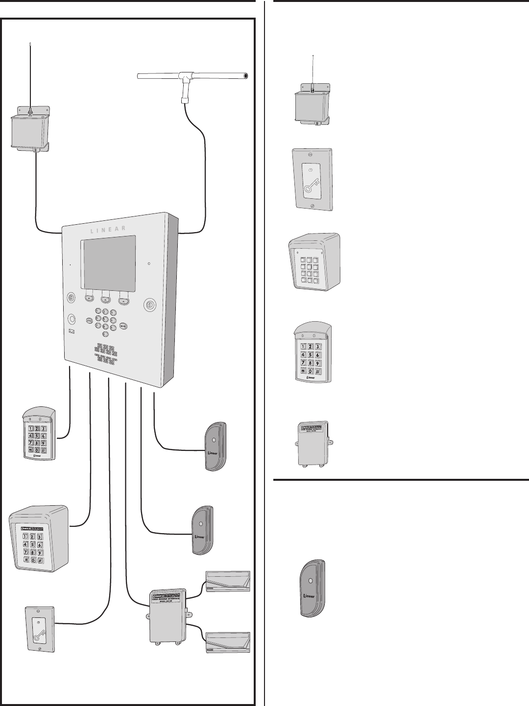
Accessory Overview PBUS Accessories
Several compatible accessories are available to connect to the three
6-wire communications “PBUS” inputs. Up to six PBUS accessories can
be used with each AE2000Plus unit.
AM-RRR Remote Radio Receiver
For wireless transmitters, connect the Model
AM-RRR high-gain superheterodyne UHF receiver.
The receiver is housed in a weather-resistant
enclosure and can be mounted indoors or
outdoors. Gaskets and a weather-tight wiring strain
relief seal the unit from the elements.
AM-RPR Radio Proximity Receiver
The Model AM-RPR functions as a remote device
that supplies localized radio reception for the
AE2000Plus In a typical installation, the AM-RPR
would be mounted in a plastic single-gang electrical
box next to the controlled opening. When the user
requires access, their transmitter must be activated
within three inches of the AM-RPR faceplate.
AM-KP Exterior Keypad
The Model AM-KP is housed in a rugged cast
aluminum enclosure designed for exterior
installations. The die-cast keys have bright,
easy-to-read yellow graphics. The keypad can
be mounted to a pedestal or directly to a wall.
A keylock secures the keypad to the mounting
backplate.
AM-KPI Interior Keypad
The Model AM-KPI keypad is housed in a rugged,
plastic enclosure designed to be mounted indoors
in a standard single-gang electrical box. Tamper
resistant screws secure the keypad to its mounting
plate. The die-cast keys have bright, easy-to-read
yellow graphics and is illuminated with white
LEDs. The keypad is supplied with a satin-chrome
bezel and three interchangeable colored bezels
(white, ivory, & bronze) to customize the keypad
appearance for the installation.
AM-CRI Card Reader Interface
The Model AM-CRI expands the standard two
AE2000Plus Wiegand inputs by supporting one
or two additional 26-bit Wiegand input devices per
AM-CRI interface used.
Wiegand Accessories
The two WIEGAND format inputs connect WIEGAND devices to the
AE2000Plus. Linear offers a Wiegand format proximity reader. Most other
manufacturer’s 26, 30 & 31-bit WIEGAND output devices can also be
used with the AE2000Plus.
AM-PR Proximity Reader
The Model AM-PR is a radio-based reader that
works with either proximity tags (Model AM-PT) or
proximity cards (Model AM-PC), both of which are
slotted to attach to key rings. Upon reading a user’s
tag or card, the reader sends the entry data via a
Wiegand output to the AE2000Plus. An integral
LED confi rms to the user that access is granted.
AM-RRR
*
5
6
7
8
9
0
#
1
2
3
4
AM-KP
AM-KPI
AM-RPR
AM-PR
AM-CRI
AM-RRR
REMOTE
RADIO
RECEIVER
EXA-2000
REMOTE
RADIO
ANTENNA
AM-RPR
RADIO
PROXIMITY
RECEIVER
AM-KP
EXTERIOR
KEYPAD
AM-KPI
INTERIOR
KEYPAD
AM-CRI
CARD
READER
INTERFACE
AM-PR
PROXIMITY
READERS
PBUS
ACCESSORIESWIEGAND
ACCESSORIES
AE2000PLUS
TELEPHONE ENTRY
& ACCESS CONTROL
SYSTEM
WIEGAND
CARD
READERS

5
Component Locations
OPTIONAL
CAMERA
DISPLAY
LEFT
CABINET
LOCK
OPTIONAL
POSTAL
LOCK
SPEAKERKEYPAD
MICROPHONE
RELAY
TERMINALS
WIEGAND
INPUT
TERMINALS
TAMPER
SWITCH
RECEIVER
RANGE KNOB
ANTENNA
CONNECTOR
MICROPHONE
POSTAL LOCK
MOUNTING
PLATE
SPEAKER
PROMPT SPEECH
VOLUME
ADJUSTMENT
CPU/INTERFACE
CONNECTOR
VIDEO
CONNECTOR
CAMERA
CONNECTOR
(HIDDEN)
OPTIONAL
CAMERA
PBUS
TERMINALS
NETWORK
TERMINALS
AM-MIO
INTERFACE
TELEPHONE
INTERFACE
CONNECTOR
TAMPER
MAGNET
SYSTEM
RESTART
BUTTON
RESIDENT'S VOICE
VOLUME
ADJUSTMENT
FOR EASY WIRING, THE UNIT'S TERMINAL BLOCKS
CAN BE UN-PLUGGED FROM THE CIRCUIT BOARD
INSTALLATION NOTE:
TAMPER
SWITCH
CONNECTOR
EARTH
GROUND
STUD
POWER
TERMINALS
TELEPHONE
TERMINALS
TELEPHONE
JACK MAIN POWER
SWITCH
RS-232
PORT
PROCESSOR MODULE
POWER CONNECTOR
FUNCTION
BUTTONS
KEYPAD
POWER
CONNECTOR
RIGHT
CABINET
LOCK
6
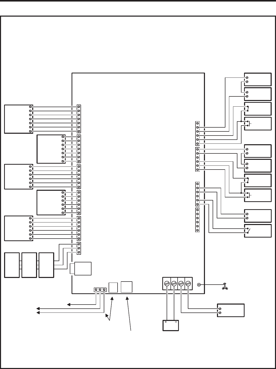
Wiring Diagram
AE2000PLUS
THIS WIRING EXAMPLE SHOWS:
DOOR ACCESS WITH A DOOR STRIKE ON RELAY CHANNEL "A"
DOOR ACCESS WITH A MAGNETIC LOCK ON RELAY CHANNEL "B"
GATE ACCESS WITH A GATE OPERATOR ON RELAY CHANNEL "C"
(YOUR INSTALLATION MAY VARY)
GND
DAT 0
DAT 1
LED1
HOLD
PWR
LED2
GND
DAT 0
DAT 1
LED1
HOLD
PWR
LED2
GND
DAT1
DAT0
DVAL
PCLK
PWR
GND
DAT1
DAT0
DVAL
PCLK
PWR
GND
DAT1
DAT0
DVAL
PCLK
PWR
NET-A
GND
NET-B
GND
DS-B
N.O.
COM
N.C.
RTE-B
GND
DS-A
N.O.
COM
N.C.
RTE-A
RING
TIP
EARTH GND
POWER
TERMINALS
12-24 VOLTS AC/DC
READER A
TERMINALS
READER B
TERMINALS
PBUS "A"
TERMINALS
PBUS "B"
TERMINALS
PBUS "C"
TERMINALS
NETWORK
TERMINALS
TELEPHONE
TERMINALS
TELEPHONE
JACK
RS-232
PORT DC + DC - AC AC
RELAY
CHANNEL "A"
TERMINALS
RELAY
CHANNEL "B"
TERMINALS
GND
DS-D
N.O.
COM
N.C.
RTE-D
GND
DS-C
N.O.
COM
N.C.
RTE-C
RELAY
CHANNEL "C"
TERMINALS
RELAY
CHANNEL "D"
TERMINALS
RELAY RATING:
3 AMPS @ 30 VOLTS
AC/DC MAXIMUM
EARTH
GROUND
STAKE
GROUND
STUD
WIEGAND
DEVICE
LED2
HOLD
LED1
DAT 1
DAT 0
GND
PWR
WIEGAND
DEVICE
LED2
HOLD
LED1
DAT 1
DAT 0
GND
PWR
PBUS
DEVICE
PCLK
DVAL
DAT0
DAT1
GND
PWR
PBUS
DEVICE
PCLK
DVAL
DAT0
DAT1
GND
PWR
PBUS
DEVICE
PCLK
DVAL
DAT0
DAT1
GND
PWR
MULTIPLE NETWORK UNITS
REFER TO NETWORK SECTION
FOR WIRING OPTIONS
EARTH
GROUND
TO DEDICATED
TELEPHONE LINE
CONNECT TELEPHONE LINE TO
TERMINALS OR TELEPHONE JACK
FOR LOCAL COMPUTER CONNECTION
USE LINEAR MODEL A2C
SERIAL COMPUTER CABLE
16 VAC
50 VA
TRANSFORMER
12 VOLT
BATTERY
NOTE: OPTIONAL
BACKUP BATTERY
WILL REQUIRE AN
EXTERNAL CHARGER
ELECTRIC
DOOR
STRIKE
DOOR
STRIKE
POWER SUPPLY
DOOR EXIT
REQUEST
BUTTON
GATE
OPERATOR
OPEN
DOOR
SENSE
CONTACT
GATE
EXIT LOOP
SENSOR
MAGNETIC
DOOR
LOCK
DOOR
LOCK
POWER SUPPLY
DOOR EXIT
REQUEST
BUTTON
DOOR
SENSE
CONTACT
NETWORK
UNIT
NETWORK
UNIT
NETWORK
UNIT
AM-MIO
INTERFACE
7
Important Mounting Requirements
The AE2000Plus Telephone Entry System can be installed for public
or private use. The mounting requirements will vary depending on
the installation. Review the following information before beginning the
installation.
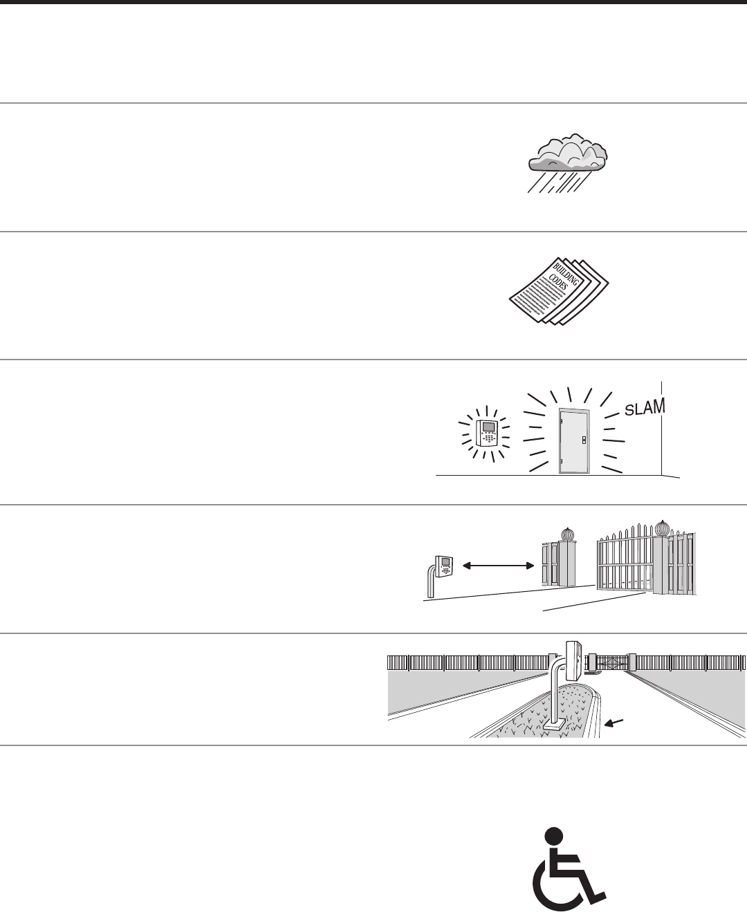
Mounting Environment
Consider the environmental factors at the desired mounting location. The
AE2000Plus is designed for direct outdoor installations, however, it is
preferable to protect the unit from extreme exposure to sun, driving rain,
or snow whenever possible. Mounting the unit in a kiosk can provide extra
environmental protection.
Follow Building Codes
Check all local building codes and ordinances prior to installing the
system. Proper installation of the AE2000Plus conforming to the local
building codes for access control equipment is a regulatory requirement.
The AE2000Plus installation is an extremely important and integral part
of the overall access control system.
Mounting Location
If the AE2000Plus is used to control a door or pedestrian gate, locate
the unit as near as practical to the entry point. If the unit is mounted on
or in a wall adjacent to the entry point, be sure the wall is sturdy. The
repeated shock and vibration from a slamming access door or spring-
loaded pedestrian gate must be isolated from the AE2000Plus. NEVER
MOUNT THE UNIT DIRECTLY TO A MOVING DOOR OR GATE!
Gate Installations
If the AE2000Plus is used to control a gate operator connected to a
vehicular gate, the unit MUST be mounted AT LEAST 10 feet away from
the gate (open and closed) and gate operator. AT NO TIME SHOULD A
PERSON BE ABLE TO TOUCH THE GATE OR GATE OPERATOR AND
THE AE2000Plus AT THE SAME TIME.
Vehicle Traffi c
Do not mount the AE2000Plus where it extends into any traffi c lane. Locate
the gooseneck pedestal or entry kiosk so all parts of the AE2000Plus are
outside the traffi c lane. Locate the AE2000Plus clear of any turn-around
lanes vehicles use when access is denied.
Americans with Disability Act (A.D.A.) Requirements
THE FOLLOWING WHEELCHAIR ACCESS REQUIREMENTS ARE
FOR PUBLIC DOOR CONTROL INSTALLATIONS ONLY.
1. If the clear fl oor space allows only forward approach to the system,
the maximum high forward reach allowed is 48” above grade to the
top of the keypad.
2. If the high forward reach to the system is over an obstruction of
greater than 20” but less than 25”, the maximum high forward
reach allowed is 44” above grade to the top of the keypad.
3. If the clear fl oor space allows parallel approach by a person in a
wheelchair, the maximum high side reach shall be 54” above grade
to the top of the keypad.
4. If the high side reach is over an obstruction of 24” or less, the
maximum high side reach allowed is 46” above grade to the top of
the keypad.
EDGE OF
TRAFFIC LANE
10 FEET
MINIMUM
!
?
?
?
?
?
?
8
Entry System Mounting
The AE2000Plus cabinet is designed to be mounted three ways:
• The unit can be mounted directly to a wall or fl at surface.
• The unit can be mounted recessed into the wall.
• The unit can be mounted on a standard gooseneck pedestal.
Choose a well lit location near the controlled opening. Wiring access for
power, telephone, earth ground, control output must be available to the
mounting location. If the optional remote accessories are used, wiring
access for these cables must also be available to the mounting location.
Opening and Closing the Cabinet
The AE2000Plus’s cabinet hinges are spring loaded to help weather seal
the cabinet. To open the cabinet, press the cabinet door fi rmly around
each lock while turning each key counterclockwise. To close the cabinet,
press the cabinet door fi rmly around each lock while turning each key
clockwise.
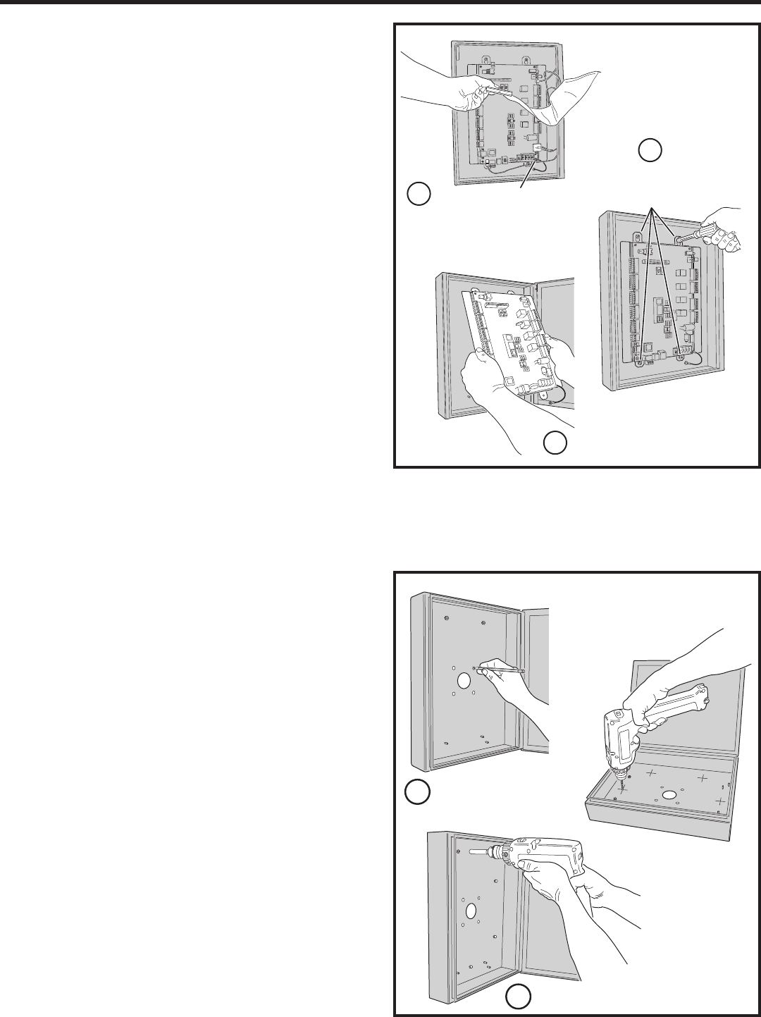
Mounting Preparation
Before mounting the system, the main circuit board mounting plate
must be removed to provide access for the wiring hole and mounting
fasteners.
✦ CAUTION!: Touch a grounded object before proceeding to
discharge static electricity from your body.
1. Carefully remove the fi ve main circuit board wiring connectors:
• The CPU/interface ribbon cable connector.
• The processor module power connector.
• The telephone interface connector.
• The tamper switch connector.
• The keypad power connector.
2. Remove the nut from the Earth Ground stud and remove the green
ground wire lug from the stud.
3. Remove the two bottom circuit board mounting plate nuts.
4. Loosen the two top circuit board mounting plate nuts.
5. Carefully lift up on the mounting plate, removing the circuit board
mounting plate. Set it aside in a safe place.
Reverse these steps to replace the circuit board mounting plate after the
cabinet mounting is complete.
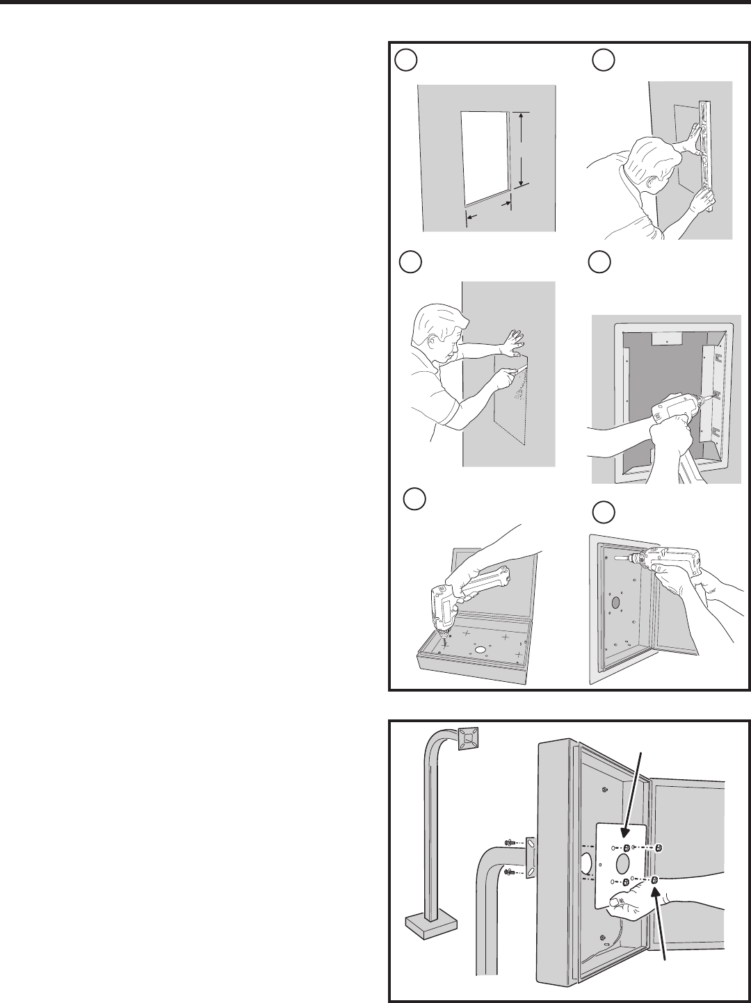
Surface Mounting
The cabinet can be mounted on a wall or any suitable fl at surface. The
four 3/8” mounting holes or the four self-drill locations can be used to
attach the cabinet to the surface.
1. For wall mounting, hold the cabinet at the approximate mounting
location where the display will be about eye level or slightly above.
2A. If using the 3/8” mounting holes, mark the four mounting hole
centers. Drill as required. Use the appropriate fasteners for the
mounting surface to secure the cabinet.
2B. If using the self-drill mounting holes, choose the correct size bit for
the fasteners and drill the cabinet as required. Use the appropriate
fasteners for the mounting surface to secure the cabinet.
3. After routing the wiring into the cabinet, replace the circuit board
mounting plate and plug in the wiring connectors. Be sure to
replace the green ground wire.
MARK THE FOUR
MOUNTING HOLES
ATTACH THE CABINET WITH APPROPRIATE
HARDWARE FOR THE MOUNTING SURFACE
DRILL THE CABINET AT THE
PRE-MARKED LOCATIONS
OR
SURFACE
MOUNTING
1
2
CAREFULLY REMOVE THE
FIVE WIRING HARNESS
CONNECTORS & GROUND WIRE
LOOSEN THE TOP
TWO NUTS & REMOVE
THE BOTTOM TWO NUTS
CAREFULLY REMOVE THE
CIRCUIT BOARD
MOUNTING
PREPARATION
GROUND WIRE STUD
1
2
3
9
Entry System Mounting (Continued)
Recessed Mounting
The cabinet can be mounted recessed using the accessory trim-ring
(P/N ACP00914). The trim-ring mounts in the wall and the cabinet
attaches to the trim-ring.
1. Identify the location of any studs in the wall.
2. Cut a 15-½” wide by 19” high rectangular hole between studs at
the mounting location.
3. Install any additional mounting material required to provide
surfaces inside the wall 15-½” apart for attaching the trim-ring.
4. Place the trim-ring in the wall hole. Check for level, then attach the
trim-ring with up to six screws into the side tabs.
5. Drill the cabinet’s six self-drill mounting holes the appropriate size
for the hardware.
6. Attach the cabinet to the trim-ring using self-tapping screws.
7. After routing the wiring into the cabinet, replace the circuit board
mounting plate and plug in the wiring connectors. Be sure to
replace the green ground wire.
Pedestal Mounting
The cabinet can be mounted on a gooseneck pedestal. Linear
manufacturers two pedestals: Model GNC-1 is for surface mounting with
concrete fasteners, Model GNB-1 is for burial mounting. When mounting
to a pedestal, use the cabinet reinforcing plate to stiffen the cabinet.
1. Install the pedestal at the desired location.
2. Place the reinforcing plate inside the cabinet.
3. Use security hardware to attach the cabinet and reinforcing plate
to the pedestal.
4. After routing the wiring into the cabinet, replace the circuit board
mounting plate and plug in the wiring connectors. Be sure to
replace the green ground wire
PEDESTAL
ALIGN THE REINFORCING PLATE
ON THE INSIDE OF THE CABINET
USE SECURITY HARDWARE
TO ATTACH THE PLATE AND
CABINET TO THE PEDESTAL
PEDESTAL
MOUNTING
MARK HOLE LOCATION
4INSTALL ANY SHIMS TO
ALLOW MOUNTING AND
ATTACH THE TRIM-RING
WITH UP TO 6 SCREWS
5
6
DRILL 3/16" HOLES IN
THE CABINET AT THE
PRE-MARKED LOCATIONS
ATTACH THE CABINET TO
THE TRIM-RING WITH
SELF-TAPING SCREWS
DETERMINE LOCATION FOR
THE 15-½" x 19" MOUNTING HOLE
3CUT MOUNTING HOLE
1 2
RECESSED
MOUNTING
19"
15-½"
10
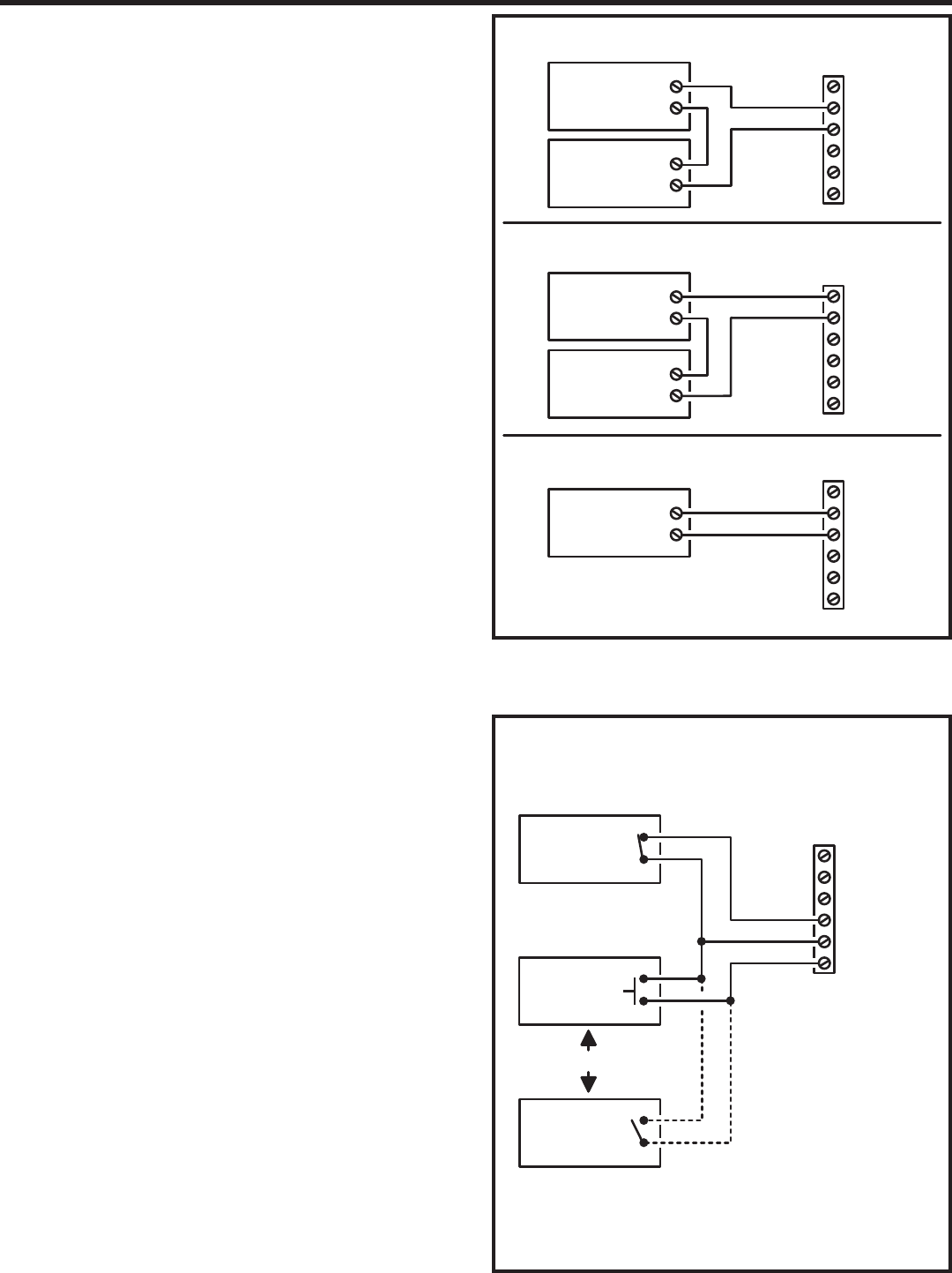
Relay Output Wiring
Any of the four relay outputs channels (A-D) can be used to control
access devices on doors or gates.
Door or Pedestrian Gate Control
1. Install a low voltage electric door strike or magnetic lock as a
locking device for the door or pedestrian gate.
2. Install the power supply or transformer for the locking device. DO
NOT POWER THE AE2000Plus FROM THIS POWER SUPPLY.
3. Connect one wire from the power supply to one wire from the
locking device.
4. Route two wires between the locking device and the AE2000Plus.
Connect one wire to the remaining wire of the locking device.
Connect the other wire to the remaining wire of the power supply.
5A. For a door strike, connect the wires to the AE2000Plus relay COM
& N.O. terminals.
5B. For a magnetic lock, connect the wires to the AE2000Plus relay
COM & N.C. terminals.
Gate Control
1. Route two wires between the gate and the AE2000Plus.
2. Connect the gate operator’s OPEN terminals to the AE2000Plus
relay COM & N.O. terminals.
✦ NOTE: For operator wiring specifi cs, refer to the gate operator’s
wiring diagram.
Request-to-Exit Inputs
Each of the four relay outputs has a request-to-exit input terminal.
Grounding this terminal will activate the associated relay. Exit request
inputs are typically used with push bars, loop sensors, or pushbuttons.
1. Install the pushbutton or device to signal an exit request.
2. Route two wires from the device to the AE2000Plus.
3. Connect the device’s normally open output to the wires.
4. To activate a relay channel, connect the wires to the associated
relay request-to-exit terminal (RTE-A, RTE-B, RTE-C, or RTE-D)
and GND terminals.
Sensing Inputs
The sensing inputs can connect to a door switch that monitors whether
the controlled door is open or closed.
1. To use the door sense feature to detect forced entry or door ajar
conditions, install a normally closed door switch on the door
or pedestrian gate and route two wires from the switch to the
AE2000Plus.
2. Connect the sensing device wires to the associated relay sensing
terminal (DS-A, DS-B, DS-C, or DS-D) and GND terminals.
GND
DS
N.O.
COM
N.C.
RTE
RELAY RATING:
3 AMPS @ 30 VOLTS
AC/DC MAXIMUM
TYPICAL DOOR STRIKE HOOKUP
TYPICAL MAGNETIC LOCK HOOKUP
TYPICAL AUTOMATIC GATE HOOKUP
ELECTRIC
DOOR
STRIKE
DOOR
STRIKE
POWER SUPPLY
GND
DS
N.O.
COM
N.C.
RTE
MAGNETIC
DOOR
LOCK
DOOR
LOCK
POWER SUPPLY
GND
DS
N.O.
COM
N.C.
RTE
GATE
OPERATOR
OPEN
RELAY
TERMINALS
GATE
EXIT LOOP
SENSOR
DOOR
SENSE
CONTACT
GND
DS
N.O.
COM
N.C.
RTE
RELAY
TERMINALS
NOTE: DOOR
SENSE CONTACT
IS NORMALLY CLOSED
DS = SENSING INPUT
RTE = REQUEST-TO-EXIT
DOOR EXIT
REQUEST
BUTTON
OR
NOTE: DOOR EXIT REQUEST BUTTON
AND GATE EXIT LOOP CONTACT
ARE NORMALLY OPEN

11
Power, Battery, & Ground Wiring
Power Wiring
✦ NOTE: DO NOT APPLY POWER UNTIL THE INSTALLATION IS
COMPLETE. TURN MASTER POWER SWITCH OFF BEFORE
WIRING.
1. Route two wires between the AE2000Plus and the power
transformer.
• For power wire runs up to 75 feet, use 18 AWG, THHN 600-volt
insulated wire.
• For power wire runs up to 150 feet, use 16 AWG, THHN 600-volt
insulated wire.
2. Connect the wires to the transformer. Connect the other end of the
wires to the AE2000Plus AC1 & AC2 terminals.
Backup Battery / Uninterruptable Power Supply
Use of battery backup is optional. It will allow the AE2000Plus to operate
for short periods of time without AC power. The door or gate access
device must use some type of battery backup of its own for the entire
system to be functional.
A backup battery will not fi t into the AE2000Plus case. Protect the backup
battery inside a rain-tight NEMA enclosure suitable for the installation.
✦ NOTE: A backup battery is not required to maintain the
AE2000Plus clock/calendar and programming memory during
power outages.
1. Route two wires between the AE2000Plus and the backup battery.
2. Connect the Battery positive to the AE2000Plus DC+ terminal and
the negative to the DC- terminal.
✦ NOTE: The AE2000Plus does not supply battery charging
current. An external battery charger will be required to maintain the
battery.
Earth Ground
For the best ground, use size 12 gauge solid wire or larger to connect to
an 8-foot copper ground rod. Locate the ground rod next to the Power and
Telephone company rods and bond the rods together with a new clamp.
Do not disturb the clamps installed by the Power or Telephone Company.
Alternately, connect to a metallic cold water pipe for the earth ground.
1. Connect the wire from the earth ground to the AE2000Plus
EARTH GROUND STUD.
RS-232 Port
A modular connector is provided for the bi-directional 38.4K baud RS-232
port. The AE2000Plus’s RS-232 port connects to a personal computer’s
COM port. System programming can be performed locally with a computer
connected to the RS-232 port using the AccessBase 2000 software.
16 VAC
50 VA
TRANSFORMER
EARTH
GROUND
STAKE
12 VOLT
BATTERY
POWER
TERMINALS
EARTH
GROUND
STUD
NOTE: THE OPTIONAL
BACKUP BATTERY
WILL REQUIRE AN
EXTERNAL CHARGER
DC
DC
AC2
AC1
AE2000PLUS
RS-232 PORT
COMPUTER'S
COM PORT
LINEAR MODEL A2C
SERIAL COMPUTER CABLE
SET COMPUTER COM PORT
BAUD RATE TO 38,400 BPS
NOTE: USE A DB-25 TO DB-9 CABLE ADAPTER IF REQUIRED
12
Telephone Wiring
For telephone entry and programming, the AE2000Plus connects to a
standard telephone line.
Important Telephone Wiring Tips
• DO NOT ROUTE TELEPHONE AND AC WIRING INSIDE THE
SAME CONDUIT. Route all telephone wires inside a dedicated
conduit that is at least six inches away from any AC line wiring.
• All telephone wiring must be made on the “building” side of the
telephone company’s demarcation device (the terminal block
where the telephone line connects to the building).
• If any security system or personal alert system at the installation is
connected to the telephone line, be sure that it is connected to the
line ahead of the AE2000Plus using a RJ-31X or RJ-38X interface.
• Use only high-quality telephone wire. All telephone wire should be
twisted-pair with a minimum size of 24 AWG.
Typical Telephone Wiring
1A. If using the AE2000Plus modular connector for the telephone
connection, connect a double-ended modular cable between the
AE2000Plus PHONE jack and the modular telephone jack wired to
the installation’s telephone line.
1B. If using the AE2000Plus terminal block for the telephone
connection, before connecting the telephone line, check the
polarity of the wires with a DC voltmeter. Connect the negative wire
(usually green) to the RING terminal. Connect the positive wire
(usually red) to the TIP terminal.
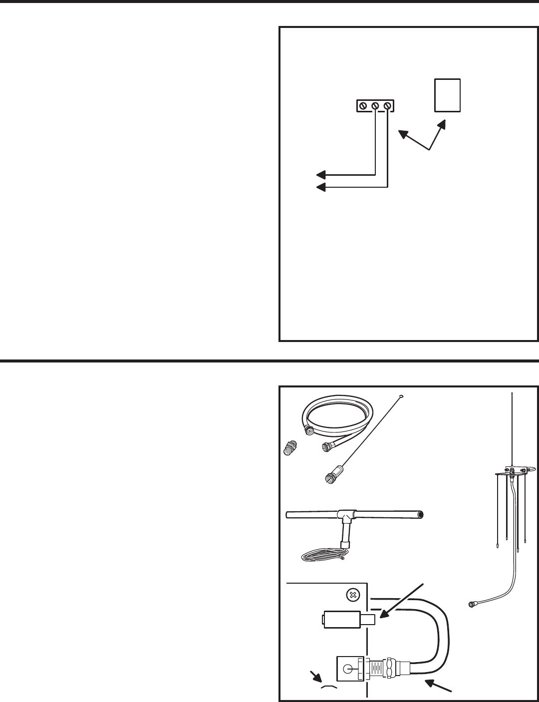
Optional Radio Antenna
If wireless transmitters are going to be used in the system a remote
antenna must be installed to provide reception for the AE2000Plus.
A basic antenna kit is supplied with the AE2000Plus. The kit contains a
whip antenna, connector, and a 36” length of coax cable. The antenna
connector should be mounted on a metal surface using a 3/8” hole.
Two other models of antennas are compatible with the AE2000Plus. The
Model EXA-1000 is a non-directional antenna. The Model EXA-2000 is
a directional antenna used in installations where transmitted signals are
desired to be received only in a particular direction.
✦ NOTE: Up to 50 feet of type RG-59 coax can be used to connect
the antenna to the AE2000Plus. Keep the coax as short as possible.
1. Install the antenna. (See installation instructions if using the
EXA-1000 or EXA-2000.)
2. Connect the antenna coax cable to the antenna and route the
cable to the AE2000Plus.
3. Connect the cable to the AE2000Plus ANTENNA connector.
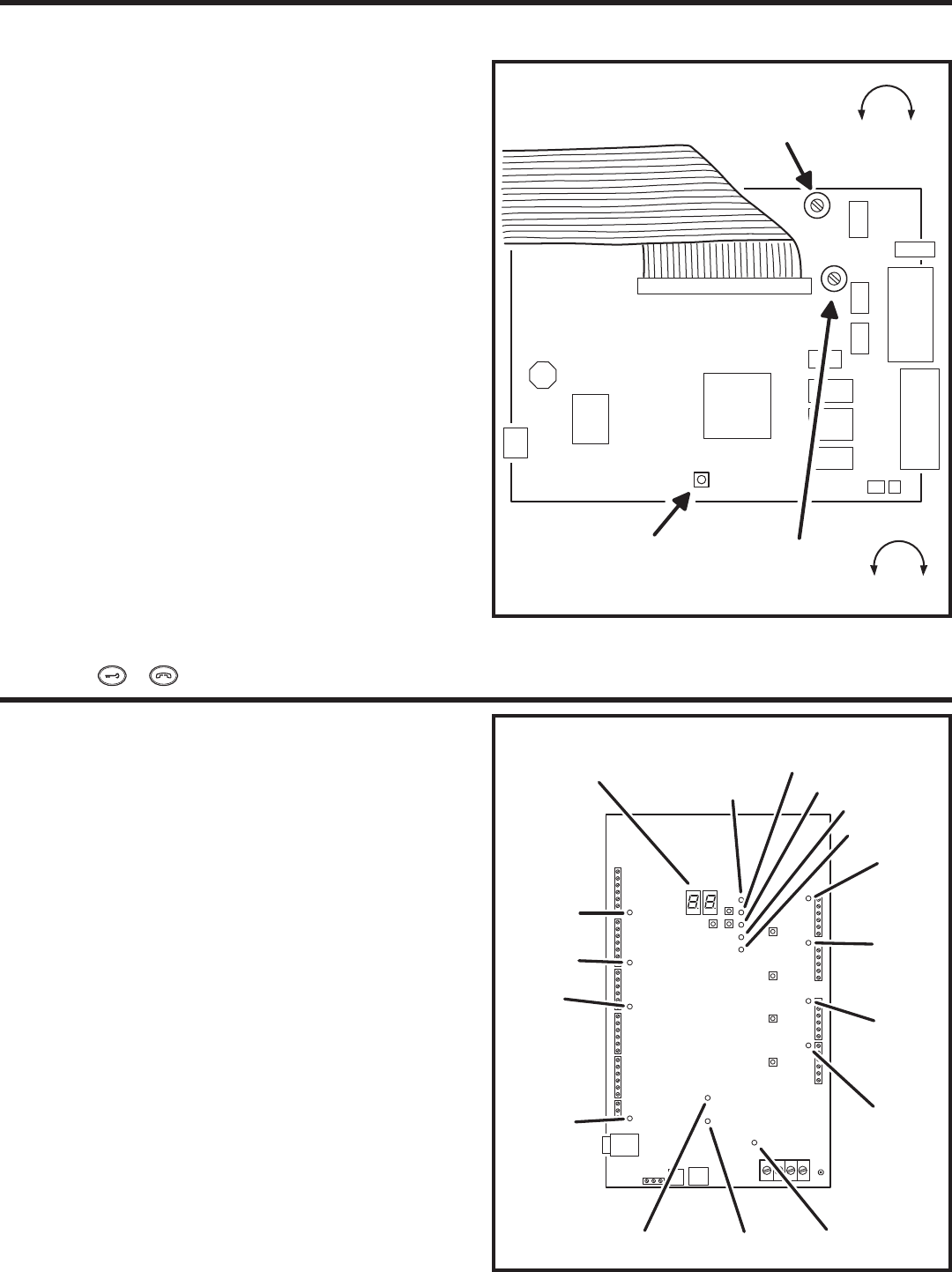
Receiver Range Control
The AE2000Plus has a RECEIVER RANGE adjustment knob. In some
installations, it may be necessary to reduce the effective radio range of
the receiver to limit the distance that transmitters can be used. Reducing
the radio’s sensitivity may also help in installations where unwanted
interference is overpowering signals from transmitters.
1. After the installation and system programming is complete,
adjust the RECEIVER RANGE knob to suit the installation. Test
transmitters from typical locations that they will be used. Set the
radio range so the receiver can activate from transmitters from
about 25% more distance than required.
TELEPHONE
TERMINALS
EARTH
RING
TIP
TELEPHONE
JACK
TO THE INCOMING
DEDICATED TELEPHONE LINE
CONNECT TELEPHONE
LINE TO TERMINALS OR
TELEPHONE JACK
NOTE: THE EARTH
TERMINAL CAN BE
USED TO CONNECT
TO THE TELEPHONE
GROUND
RECEIVER
RANGE
KNOB
AE2000PLUS
CIRCUIT BOARD
CONNECT COAX
TO ANTENNA
CONNECTOR
RECEIVER
TEST POINT
OPTIONAL
EXA-2000
DIRECTIONAL
ANTENNA
OPTIONAL EXA-1000
OMNI-DIRECTIONAL
ANTENNA
SUPPLIED
ANTENNA
KIT
CONNECTOR
36" COAX
WHIP
ANTENNA
13
Optional Color CCTV Camera
Linear’s Model CCM-1 (P/N ACP00904) CCTV camera can be installed
inside the AE2000Plus Entry System. The camera provides a video
signal for viewing the area in front of the entry system.
The CAMERA connector is used to connect the camera to the
AE2000Plus. The 4-conductor cable routes power to, and video from the
camera.
The VIDEO jack is the camera output for connection to a video cable with
a Type “BNC” connector. Up to 400 feet of 75-ohm RG-59 video cable can
be used. Longer cable runs may require the use of a video amplifi er.
Camera Installation
1. Remove the two plate locknuts from the camera mounting studs
above the right keylock on the AE2000Plus faceplate.
2. Remove the cover plate.
3. Remove the protective backing from the plastic window included
with the camera and install the plastic window onto the studs with
the adhesive side against the door.
4. Remove the lens cap from the camera.
5. Mount the camera assembly on the two studs, with the alignment
hole in the camera bracket towards the top. Secure the camera
with the two locknuts.
6. Connect the camera’s cable to the AE2000Plus CAMERA
connector.
7. Connect the video cable to the AE2000Plus VIDEO connector.
8. Connect the other end of the video cable to the viewing monitor or
the video distribution system.
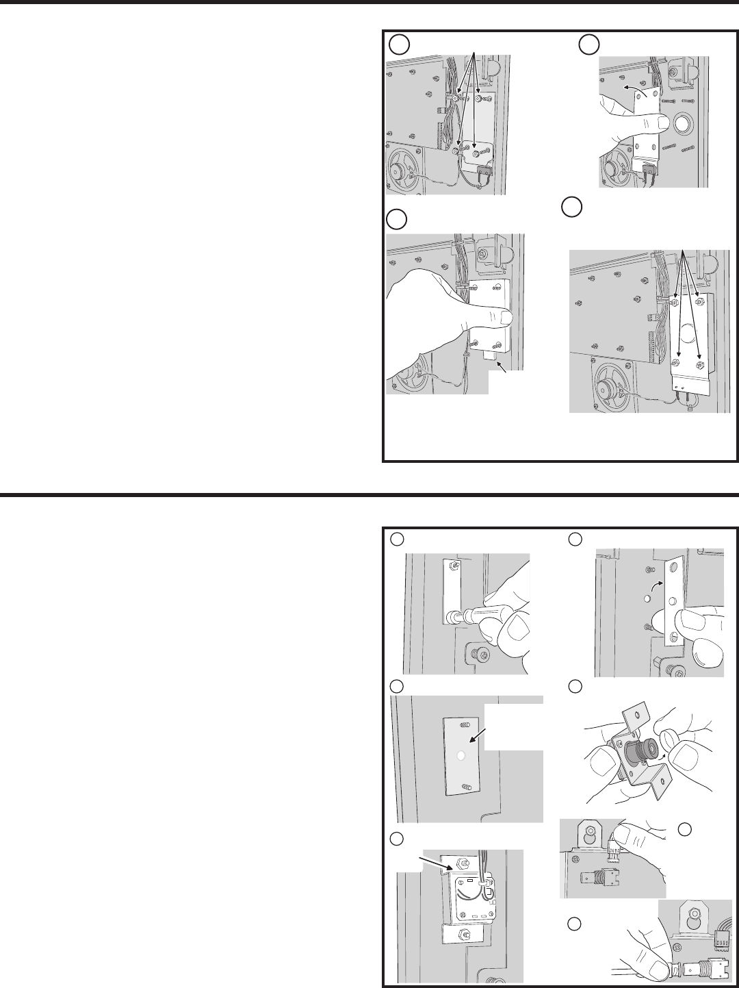
Optional Postal Lock
A postal lock can be installed in the AE2000Plus Entry System to provide
keyed access for the postal service. The AE2000Plus case is designed to
accept a U.S. Postal Service postal lock. When the postal lock is engaged,
the programmed output relay will activate.
Postal Lock Installation
1. After opening the cabinet, re-lock the left cabinet lock to provide
clearance to remove the postal lock switch plate.
2. Remove the four locknuts that retain the postal lock switch plate,
hole cover plate, and block (below the left cabinet lock on the
AE2000Plus faceplate). The hole cover plate and block will not be
used and can be discarded.
3. Remove the switch plate from the four studs.
4. Install the postal lock assembly onto the four studs. The postal
lock’s moving plunger should point down (see fi gure).
5. Replace the postal lock switch plate with the microswitch oriented
toward the front of the cabinet where it will be pressed by the
postal lock’s moving plunger (see fi gure).
6. Secure the postal lock and switch plate with the four locknuts.
✦ NOTE: Be sure the postal lock’s plunger actuates the
microswitch. Adjust the switch plate and the postal lock then test
the action until the microswitch fully actuates.
7. Tighten the four locknuts after the adjustment and testing is
complete.
8. When programming the system, set the postal lock option to
activate the desired relay output.
REMOVE LOCKNUTSREMOVE PLATE
INSTALL POSTAL LOCK
REPLACE PLATE WITH THE
MICROSWITCH TOWARDS
THE FRONT OF THE CABINET,
REPLACE LOCKNUTS
NOTE: BE SURE THE POSTAL LOCK'S PLUNGER ACTUATES THE
MICROSWITCH. ADJUST THE SWITCH PLATE AND THE POSTAL LOCK
THEN TEST THE ACTION UNTIL THE MICROSWITCH FULLY ACTUATES
4
3
2
1
PLUNGER
POINTS
DOWN
1
REMOVE PLATE RETAINING NUTS
2
34
5
6
7
REMOVE THE COVER PLATE
INSTALL THE CLEAR WINDOW REMOVE THE LENS CAP
ATTACH CAMERA WITH TWO NUTS
CONNECT
CAMERA
WIRING
HARNESS
CONNECT
VIDEO
CABLE
REMOVE PROTECTIVE
BACKING AND APPLY
WINDOW WITH
ADHESIVE SIDE
AGAINST DOOR
HOLE
ON TOP
14
PBUS Accessories
Up to six accessories (keypads, proximity readers, remote receivers) can
be connected to the three PBUS input/output ports. A typical application
for a remote keypad would be to control a second door or gate.
Linear’s PBUS devices compatible with the AE2000Plus are:
• AM-RRR Remote Radio Receiver
• AM-RGR Remote Radio Receiver
• AM-RPR Radio Proximity Receiver
• AM-KP Exterior Keypad
• AM-KPI Interior Keypad
• AM-CRI Card Reader Interface
Conventional cable or commonly available Cat-5e Ethernet cable can be
used to connect PBUS remote devices to the AE2000Plus. When using
Cat-5e cable, note that the PWR and GND connections use two wires
each to enhance the current carrying capacity for powering the remote
device.
Cable choices:
• Cat-5e Ethernet cable for wire runs up to 500'.
• 24 AWG Belden Type 9931 or equivalent for wire runs up to 300'.
• 20 AWG Weico Type 9405 or equivalent for wire runs up to 600'.
1. Mount and install the accessory as described in its instructions.
2. Route cable from the AE2000Plus to the accessory.
3. Set the DEVICE ADDRESS rotary switch in the accessory to
a unique address number. When programming the system, the
device address number will identify each PBUS accessory to the
AE2000Plus.
4. Connect the cable to the accessory and the AE2000Plus (see
PBUS wiring diagram).
Wiegand Accessories
The two AE2000Plus Wiegand inputs (WIEGAND A & B) can connect
to a large variety of 26, 30, and 31-bit Wiegand output accessories. The
Wiegand format is a common standard for access control equipment. A
typical application would be to add swipe card or proximity readers to the
system.
✦ NOTE: Depending on the Wiegand accessory used, the LED1,
LED2, and HOLD connections may not be required.
• LED1 output is switched to ground during non-access time.
• LED2 output is switched to ground for one second during access
time.
1. Mount and install the Wiegand accessory as described in its
installation instructions.
2. Route a cable from the AE2000Plus to the accessory.
• For wire runs up to 300 feet use 24 AWG Belden Type 9931 or
equivalent.
• For wire runs up to 500 feet use 20 AWG Weico Type 9405 or
equivalent.
3. Connect the cable to the accessory and the AE2000Plus as shown
in the fi gure.
REMOTE
PBUS
DEVICE
PCLK
DVAL
DAT0
DAT1
GND
PWR
GND
DAT1
DAT0
DVAL
PCLK
PWR
PBUS
TERMINALS
GND
DAT1
DAT0
DVAL
PCLK
PWR
ACCESS
CONTROL SYSTEM
PBUS TERMINALS
REMOTE PBUS
DEVICE TERMINALS
ORANGE &
ORANGE-WHITE
BROWN &
BROWN-WHITE
GREEN-WHITE
GREEN
BLUE
BLUE-WHITE
GREEN-WHITE
GREEN
BLUE
BLUE-WHITE
CAT-5e
4-UTP CABLE
UP TO 500 FEET PER DEVICE
NOTE: UP TO SIX PBUS DEVICES MAY BE CONNECTED
TO THE THREE SETS OF PBUS TERMINALS
GND
DAT1
DAT0
DVAL
PCLK
PWR
CAT-5e WIRING EXAMPLE
ORANGE &
ORANGE-WHITE
BROWN &
BROWN-WHITE
REMOTE
WIEGAND
DEVICE
LED2
HOLD
LED1
DAT1
DAT0
GND
DAT0
DAT1
LED1
HOLD
LED2
GND
WIEGAND
TERMINALS
PWR
PWR
NOTE: THE LED1, LED2, AND HOLD
CONNECTIONS MAY NOT BE REQUIRED
DEPENDING ON THE WIEGAND DEVICE USED
15
Optional Network Connections
Linear’s AE1000Plus, AE2000Plus, & AM3Plus Access Control Systems
can be connected together in a network. A network will allow sharing
programming and user information between the systems. Program each
unit to a different network Node Address (see Page 19).
✦ IMPORTANT COMPATIBILITY NOTE: Linear’s previous
access control Models AE-1000, AE-2000, & AM3 can be used in
networks with the Models AE1000Plus, AE2000Plus, & AM3Plus
only using AccessBase2000 software. The built-in AXNET
Browser Interface included in the “Plus” models is only compatible
with the Models AM3Plus, AE1000Plus, and AE2000Plus.
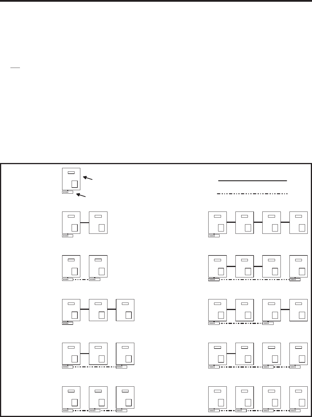
Network Confi gurations for AXNET Programming
If the system is going to be programmed using Linear’s AXNET Browser
Interface, units can communicate with each other on the network through
modems or RS-485 cable connections.
Refer to the fi gure below for details of the 11 supported AXNET network
hardware confi gurations and associated Network Confi guration Numbers.
After choosing a network layout that best suits the installation, note the
Network Confi guration Number. This number is required to be entered
during setup of the AXNET Browser Interface in the Global Settings for
Networking area.
NETWORK
CONFIGURATION #1
SINGLE
UNIT (NODE)
RS-485 CABLE CONNECTION
MODEM TELEPHONE CONNECTION
MASTER UNIT #1 ALWAYS
REQUIRES A MODEM FOR
REMOTE PROGRAMMING
#1
#1 #2
#1 #2
#1 #2 #3
#1 #2 #3
#1 #2 #3#1 #2 #3#4
#1 #2 #3#4
#1 #2 #3#4
#1 #2 #3#4
#1 #2 #3#4
NETWORK
CONFIGURATION #2
TWO RS-485
NODES
NETWORK
CONFIGURATION #3
TWO MODEM
NODES
NETWORK
CONFIGURATION #4
THREE RS-485
NODES
NETWORK
CONFIGURATION #5
TWO RS-485 NODES,
ONE MODEM NODE
NETWORK
CONFIGURATION #6
THREE MODEM
NODES
NETWORK
CONFIGURATION #7
FOUR RS-485
NODES
NETWORK
CONFIGURATION #8
THREE RS-485 NODES,
ONE MODEM NODE
NETWORK
CONFIGURATION #9
2X TWO RS-485 NODES,
TWO MODEM NODES
NETWORK
CONFIGURATION #10
TWO RS-485 NODES,
TWO MODEM NODES
NETWORK
CONFIGURATION #11
FOUR MODEM
NODES
MODEM
UNIT
AXNET COMPATIBLE NETWORK CONFIGURATIONS
16
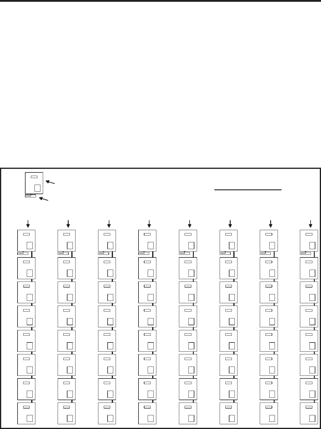
Optional Network Connections (Continued)
Network Confi guration for AccessBase2000 Programming
If the system is going to be programmed using Linear’s AccessBase2000
software, units communicate with each other on the network through
RS-485 cable connections.
AccessBase2000 does not support unit-to-unit network communications
through modems, only RS-485 cable. AccessBase2000 does support
modem communications from the PC to the eight Node #1 “master” units
on an AccessBase2000 network.
Refer to the fi gure below for design details of a fully implemented
AccessBase2000 network. The fi gure shows eight networks, each with
eight nodes, for a total of 64 units.
RS-485 CABLE CONNECTION
NETWORK NODE #1 ALWAYS
REQUIRES A MODEM FOR
REMOTE PROGRAMMING
MODEM
UNIT
(NETWORK NODE)
FULL ACCESSBASE2000 NETWORK
NODE
"
A1
"
NODE
"
A2
"
NODE
"
A3
"
NODE
"
A4
"
NODE
"
A5
"
NODE
"
A6
"
NODE
"
A7
"
NODE
"
A8
"
NETWORK
"A"
NODE
"
B1
"
NODE
"
B2
"
NODE
"
B3
"
NODE
"
B4
"
NODE
"
B5
"
NODE
"
B6
"
NODE
"
B7
"
NODE
"
B8
"
NODE
"
C1
"
NODE
"
C2
"
NODE
"
C3
"
NODE
"
C4
"
NODE
"
C5
"
NODE
"
C6
"
NODE
"
C7
"
NODE
"
C8
"
NODE
"
D1
"
NODE
"
D2
"
NODE
"
D3
"
NODE
"
D4
"
NODE
"
D5
"
NODE
"
D6
"
NODE
"
D7
"
NODE
"
D8
"
NODE
"
E1
"
NODE
"
E2
"
NODE
"
E3
"
NODE
"
E4
"
NODE
"
E5
"
NODE
"
E6
"
NODE
"
E7
"
NODE
"
E8
"
NODE
"
F1
"
NODE
"
F2
"
NODE
"
F3
"
NODE
"
F4
"
NODE
"
F5
"
NODE
"
F6
"
NODE
"
F7
"
NODE
"
F8
"
NODE
"
G1
"
NODE
"
G2
"
NODE
"
G3
"
NODE
"
G4
"
NODE
"
G5
"
NODE
"
G6
"
NODE
"
G7
"
NODE
"
G8
"
NODE
"
H1
"
NODE
"
H2
"
NODE
"
H3
"
NODE
"
H4
"
NODE
"
H5
"
NODE
"
H6
"
NODE
"
H7
"
NODE
"
H8
"
NETWORK
"B"
NETWORK
"C"
NETWORK
"D"
NETWORK
"E"
NETWORK
"F"
NETWORK
"G"
NETWORK
"H"

17
NET-A
GND
NET-B
NETWORK
UNIT "3"
NET-A
GND
NET-B
NETWORK
UNIT "4"
NET-A
GND
NET-B
NETWORK
MASTER
UNIT "1"
NET-A
GND
NET-B
NETWORK
UNIT "2"
ACCESS CONTROL HOMERUN NETWORK
USING ONE UNIT AS A NETWORK MASTER
NOTE: GROUND
CABLE SHIELDS
ONLY AT ONE END
SHIELD
SHIELD
SHIELD
NET-A
GND
NET-B
NETWORK
UNIT "3"
NET-A
GND
NET-B
NETWORK
UNIT "4"
NET-A
GND
NET-B
NETWORK
MASTER
UNIT "1"
NET-A
GND
NET-B
NETWORK
UNIT "2"
ACCESS CONTROL
NETWORK USING
"DAISY CHAIN"
WIRING
SHIELDSHIELD
SHIELD
NOTE: GROUND
CABLE SHIELDS
ONLY AT ONE END
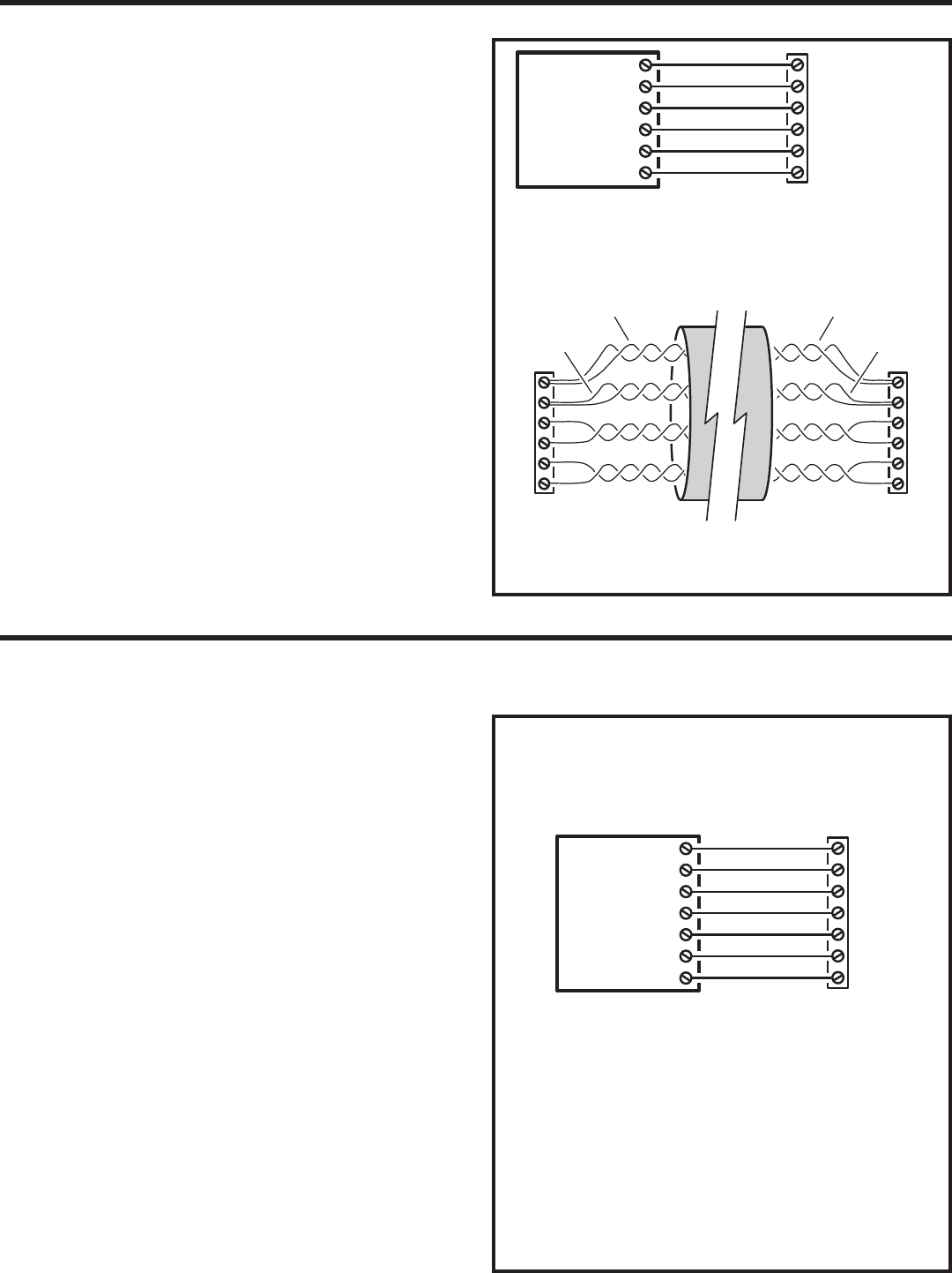
Optional Network Connections (Continued)
RS-485 Network Wiring
Network wiring conforms to 3-wire RS-485 electrical specifi cations. Units
connected in the network can be wired using one unit as a “hub” or by
wiring from one unit to the next in “daisy-chain” fashion. See the fi gures
for wiring options.
• Use Belden 9925 or Carol C0600 shielded cable or equivalent.
Maximum wire run distance is 4000 feet.
✦ NOTE: Be sure to connect the cable’s shield to one of the GND
terminals.
Network Wiring with Hub
1. Mount and install the units for the network.
2. Choose one unit to be the Network Hub. Usually this would be a
centrally located or “master” unit.
3. Route 3-conductor shielded cable from the hub unit to one of the
other units. Repeat this step to connect the hub unit to each of the
other units.
4. Connect the 3-conductor cable to each unit’s NETWORK
terminals.
Network “Daisy-chain” Wiring
1. Mount and install the units for the network.
2. Route 3-conductor shielded cable from one unit to the next unit
until there is cabling run to all of the units.
3. Connect the 3-conductor cable to each unit’s NETWORK
terminals.
18
System Adjustments
The factory settings are suffi cient for most installations. The system can
be adjusted to customize the installation.
System Volume Adjustment
The sound level of the synthesized voice and key beep can be adjusted.
1. Locate the SYSTEM VOLUME adjustment on the CPU circuit board.
2. Press keys on the keypad while adjusting the control until the
sound is at the desired level. Turn the adjustment clockwise for
more volume, counterclockwise for less volume.
2-Way Audio Volume Adjustment
If the resident’s voice from the speaker is too loud or not loud enough,
the speaker’s volume can be adjusted.
1. Locate the 2-WAY AUDIO VOLUME adjustment on the CPU circuit
board.
2. Make a directory number call to test the speaker volume. While
listening to the resident’s voice, turn the adjustment clockwise for
more volume, counterclockwise for less volume.
System Restart Button
Pressing the SYSTEM RESTART button will reboot the system’s
microcontroller. NO SYSTEM INFORMATION WILL BE ERASED.
Display Contrast Adjustment
If the lighting in the area or the viewing angle of the display in the
installation causes the display to look too dark or too light, the display’s
contrast can be adjusted.
1. Press the 1, 5 & 9 keys at the same time. The system will assume
Contrast Adjustment Mode for 15 seconds.
2. Press the up and down arrow keys until display has the best
visibility.
3. Press the or key to exit Contrast Adjustment Mode.
System Diagnostics
Several components on the main circuit board are for monitoring the
system during operation. When calling for technical assistance, Linear’s
Technical Services Department may ask the installer to use these
components to diagnose the system.
On-board Indicators
17 LED indicators are on the main circuit board. Refer to the fi gure for the
location of each indicator.
• STATUS/PROGRAM DISPLAY shows supervisory and status conditions,
also used for some local programming.
• ACCESS GRANTED lights when a credential is validated and access is
granted.
• HOST ON-LINE lights when the Host PC is connected to the Master
Node.
• VALIDATE lights when a credential is determined to be valid.
• DECODE lights when a credential has been successfully decoded.
• RADIO fl ashes when data or interference is received by the built-in radio.
• RELAY “A” ACTIVE lights when the Channel “A” relay is energized.
• RELAY “B” ACTIVE lights when the Channel “B” relay is energized.
• RELAY “C” ACTIVE lights when the Channel “C” relay is energized.
• RELAY “D” ACTIVE lights when the Channel “D” relay is energized.
• POWER lights when AC or DC power is present.
• OFF-HOOK lights when the system has the incoming telephone line
seized.
• TALK lights when the system is communicating over the telephone line.
• NETWORK fl ashes in response to network traffi c.
• PBUS blinks when any PBUS device is successively decoded.
• READER “B” fl ashes when Wiegand B device is successfully decoded.
• READER “A” fl ashes when Wiegand A device is successfully decoded.
AE2000PLUS
CPU CIRCUIT BOARD
SYSTEM
VOLUME
ADJUSTMENT MORE
LESS
2-WAY AUDIO
VOLUME
ADJUSTMENT MORE
LESS
SYSTEM
RESTART
BUTTON
ACCESS
GRANTED
AE2000PLUS
MAIN CIRCUIT BOARD
STATUS/PROGRAM
DISPLAY
HOST
ON-LINE
VALIDATE
DECODE
RADIO
RELAY "A"
ACTIVE
RELAY "D"
ACTIVE
RELAY "C"
ACTIVE
RELAY "B"
ACTIVE
POWEROFF HOOKTALK
NETWORK
PBUS
READER "B"
READER "A"
19
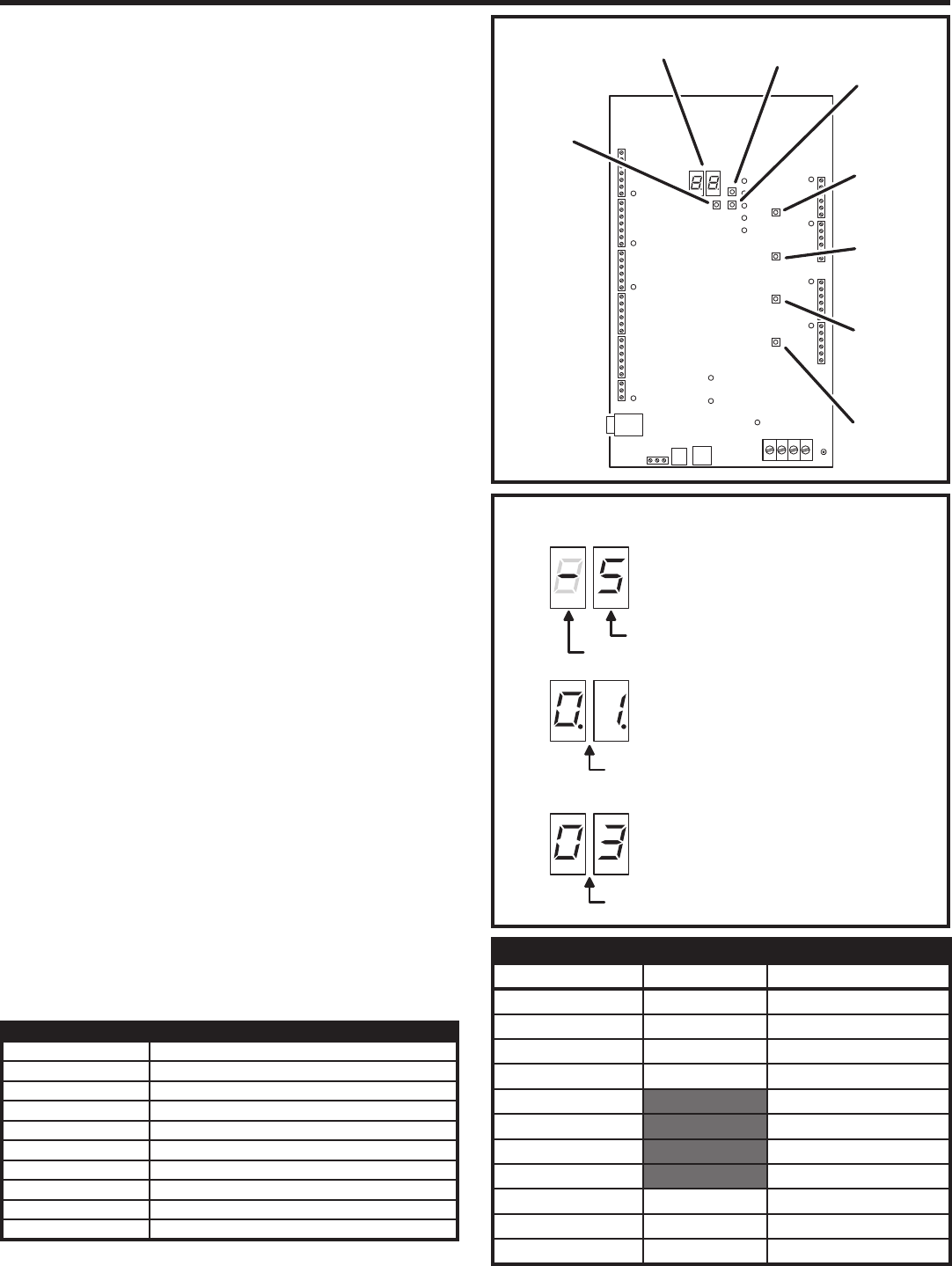
Internal Controls
On-board Pushbuttons
Seven pushbuttons are on the main circuit board. Refer to the fi gure for
the location of each pushbutton.
• UP button adds one to the value on the STATUS/PROGRAM display.
• DOWN button subtracts one from value on the STATUS/PROGRAM display.
Press with the UP button for one second to enter Programming Mode.
• ENTER button accepts the value on the STATUS/PROGRAM display
during programming, clears an indication during the supervisory display.
• RELAY “A” LATCH press to latch relay “A”, press again to unlatch.
• RELAY “B” LATCH press to latch relay “B”, press again to unlatch.
• RELAY “C” LATCH press to latch relay “C”, press again to unlatch.
• RELAY “D” LATCH press to latch relay “D”, press again to unlatch.
On-board Display
The STATUS/PROGRAM display shows the current system conditions
and is used for system setup.
Power-up
When power is applied, the display will show the current mode of operation
(AXNET “An” or AccessBase2000 “Ab”) and the version number of the
fi rmware installed. The default mode of operation is AccessBase2000.
Program Mode
Program Mode uses the display and the UP, DOWN, and ENTER
pushbuttons. The setting the network node address, operation mode, and
clearing the memory can be performed in Program Mode.
Refer to the following steps to change the system settings:
1. To enter Program Mode, press and hold the UP and DOWN
pushbuttons together for one second. While in Program Mode, both
decimal points on the display are lit.
2. The display shows the current network node number setting.
3. Press the UP or DOWN button to cycle the display through the
options that can be selected (see Program Mode Display Table).
4. When the desired option is displayed, press the ENTER button to
select the option.
✦ NOTE: In network installations, a unique network address
(1-8 for AccessBase2000, 1-4 for AXNET) must be set before
communicating with network.
✦ NOTE: If using AXNET for programming the system, select the
An programming option, for AccessBase2000 select Ab.
After the option is selected, the system will restart.
Status Mode
While the system is running, the display will show the current system
status. Normally the left digit will show a moving pattern and the right digit
will show the unit’s Network Node number.
When a supervisory condition exists, the display will cycle to show the
condition(s). When an item is displayed, press the ENTER button to clear
the display (clears the display only, the condition may still exist). Refer to
the following table for the supervisory condition display codes.
STATUS MODE DISPLAY
DISPLAY CONDITION
01 MGT TRANSMITTER STATUS EXCEPTION
02 MGT TRANSMITTER LOW BATTERY
03 MGT TRANSMITTER TAMPER
04 AC POWER FAIL (BACKUP BATTERY REQUIRED)
05 CHANNEL “A” LOCKED CLOSED
06 CHANNEL “B” LOCKED CLOSED
07 CHANNEL “C” LOCKED CLOSED
08 CHANNEL “D” LOCKED CLOSED
09 MODEM FAILURE
AE2000PLUS
MAIN CIRCUIT BOARD
RELAY "B"
LATCH
RELAY "A"
LATCH
RELAY "C"
LATCH
RELAY "D"
LATCH
"UP"
BUTTON "DOWN"
BUTTON
"ENTER"
BUTTON
STATUS/PROGRAM
DISPLAY
PROGRAM MODE DISPLAY
AccessBase2000 MODE AXNET MODE FUNCTION
0.1.0.1. SET UNIT TO NODE #1
0.2.0.2. SET UNIT TO NODE #2
0.3.0.3. SET UNIT TO NODE #3
0.4.0.4. SET UNIT TO NODE #4
0.5. SET UNIT TO NODE #5
0.6. SET UNIT TO NODE #6
0.7. SET UNIT TO NODE #7
0.8. SET UNIT TO NODE #8
A.N.A.b. SWITCH OPERATION MODE
B.L.B.L. RESERVED (DO NOT USE)
C.L.C.L. CLEAR UNIT’S MEMORY
SYSTEM IDLE
LEFT DIGIT CIRCULATES
RIGHT DIGIT SHOWS NETWORK NODE ADDRESS
DIGITS SHOW SUPERVISORY CODE
STATUS MODE
STATUS/PROGRAM
DISPLAY
DECIMAL POINTS LIGHT, DIGITS SHOW PROGRAMMING OPTION
PROGRAM MODE
20
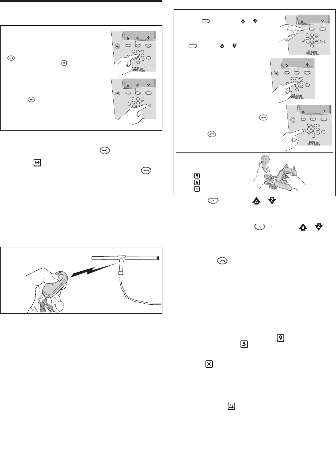
AE2000Plus Operation
Resident Access with an Entry Code
• Residents have up to 40 seconds to key in their entry code.
• Up to eight seconds are allowed between each keystroke.
• If the code is entered wrong, press the key to reset the
keypad and re-enter the correct entry code. (On remote keypads,
press the key to reset the keypad.)
• If the system is displaying the directory names, press the key
fi rst, before keying in the entry code.
• After a correct code is entered, and if the conditions for granting
access are fulfi lled, the programmed relay will activate for the
programmed time.
• If the number of incorrect codes entered exceeds the keypad
lockout count, the keypad will be locked and not accept any entries
for one minute.
• If the Anti-passback feature is enabled, the entry code will be
unusable until the anti-passback time expires.
Resident Access with a Wireless Transmitter
• Activate a wireless transmitter within radio range of the
AE2000Plus’s antenna.
• After a valid transmitter is decoded, and if the conditions for
granting access are fulfi lled, the programmed relay channel will
activate for the programmed time.
• If the Anti-passback feature is enabled, the transmitter will become
unusable until the anti-passback time expires.
Visitor Access with a Resident Call
• Press the key below the or arrow repeatedly to
scroll through the resident’s names alphabetically and display their
associated directory number.
• To scroll through the alphabet faster and choose which letter to
view, press and hold down the key below the or
arrow. Release the key when the desired letter is underlined.
• With the resident directory displayed, the visitor enters the
directory number to place a call to the resident.
• If the visitor already knows the resident’s directory number, they
can press the key then enter the directory number without
viewing the directory display.
• The system will dial the resident’s telephone number to establish
2-way communications.
✦ NOTE: The resident’s telephone number will never be displayed to
the visitor.
• If the resident is using the telephone at the same time a visitor
calls, the system will indicate to the visitor that the line is busy.
• The resident answers the call and converses with the visitor to
determine if access will be granted.
• The resident can use their telephone’s keypad to grant access
activating Relay Channel “A” by pressing , or activating Relay
Channel “B” by pressing . After access is granted, the system
will disconnect the visitor and resident call.
• The resident can disconnect the visitor without granting access by
pressing or by hanging up.
✦ NOTE: The telephone keys that the resident presses can be
customized for the installation.
• The length of time the visitor is allowed to talk can be programmed
from 15-255 seconds. The resident will hear a series of beeps
during the last 10 seconds of talk time. To restart the talk timer, the
resident can press on their telephone.
KEY IN AN ENTRY CODE AT THE SYSTEM KEYPAD
OR ENTER A CODE AT A REMOTE KEYPAD
- OR -
IF THE SYSTEM IS DISPLAYING THE DIRECTORY NAMES,
PRESS THE KEY FIRST, BEFORE KEYING IN AN
ENTRY CODE
IF THE CODE IS ENTERED WRONG, PRESS THE
KEY TO RESET THE KEYPAD AND RE-ENTER
THE CORRECT CODE (USE THE KEY TO RESET
REMOTE KEYPADS)
ACTIVATE TRANSMITTER
ANTENNA
VISITOR
RESIDENT
PRESS THE KEY BELOW THE OR REPEATEDLY
TO SCROLL THROUGH THE RESIDENT'S NAMES
- OR -
TO SCROLL THROUGH FASTER, PRESS AND HOLD
THE KEY BELOW OR THEN RELEASE
THE KEY WHEN THE DESIRED LETTER IS UNDERLINED
THE RESIDENT TALKS TO THE VISITOR
AND CAN GRANT OR DENY ACCESS
USING THEIR TELEPHONE KEYS
RELAY "A"
RELAY "B"
DISCONNECT
WITH THE RESIDENT DIRECTORY DISPLAYED,
ENTER THE RESIDENT'S DIRECTORY NUMBER TO
PLACE A TELEPHONE CALL TO THE RESIDENT
IF THE VISITOR ALREADY KNOWS THE RESIDENT'S
DIRECTORY NUMBER, THEY CAN PRESS THE KEY
THEN ENTER THE DIRECTORY NUMBER WITHOUT
VIEWING THE DIRECTORY DISPLAY
PRESSING THE KEY DURING A TELEPHONE CALL
WILL CANCEL THE CALL IN PROGRESS
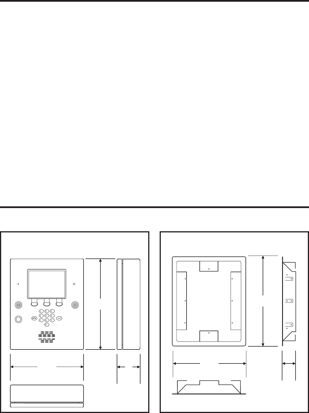
21
17-3/8"
21-1/8"
4"
OPTIONAL TRIM RING
15-1/4"
19"
4"
AE2000PLUS
Dimension Drawing
Specifi cations
MECHANICAL
Case dimensions: 15-1/4” W x 19” H x 4” D
ELECTRICAL
Voltage: 16-24 Volts AC or 12-24 Volts DC
Current: 2000 mA @ 16 VAC maximum
Backup Battery: Externally charged 12 Volt DC source, 6 amp/hr minimum
Outputs: Relay Channels A-D
Form “C” 3 Amps @ 30 Volts maximum
Inputs: Four normally closed door sense inputs
Four normally open exit request inputs
Two WIEGAND reader inputs
Three PBUS inputs
Network: Three-wire network
RADIO
Frequency: 318 MHz ± 500 KHz @ 23°C
Bandwidth: 300 KHz Typical
Sensitivity: -97 dBm Minimum (-100 dBm Typical)
Encoding: Linear MegaCode® Format
ENVIRONMENTAL
Temperature: -22°F to 149°F (-30°C to 65°C)
Humidity: 5% to 95% non-condensing

22
Troubleshooting
System completely dead
1. No power from transformer. Check voltage at transformer terminals.
2. Check voltage at AE2000Plus power terminal strip.
Buzz on speaker
1. Check for 24 volt AC power shorted to wiring conduit.
2. Check for telephone line shorted to ground.
3. Verify that telephone wires are twisted pair.
4. Verify that the AE2000Plus is connected to earth ground.
5. Check 16 VAC voltage at AE2000Plus transformer terminals.
Buzz on telephone line
1. Disconnect 16 VAC wires from terminal strip, if buzz goes away,
one side of the transformer wires is grounded.
2. Check all connections for any shorts to ground.
System will not answer an incoming call
1. Automatic telephone answer disabled.
2. AE2000Plus telephone line trouble.
Entry code will not activate relay
1. Entry code not assigned.
2. Entry code not set up for proper relay.
3. Keypad is in lockout.
Remote PBUS device does not work
1. Check remote device address switch setting.
2. Check remote device for power.
3. Be sure the device is wired correctly.
Main or remote keypad will not activate a relay
1. Entry code is not assigned.
2. Keypad may be in lockout from too many incorrect attempts. Wait
one minute for lockout to clear and try again.
3. Remote keypad wiring incorrect.
Resident’s Telephone does not ring when a visitor calls
1. Resident’s telephone number programmed incorrectly.
2. Check AE2000Plus telephone line.
3. Call resident from another line or cell phone to determine if the
resident’s telephone is working.
Transmitter does not activate relay
1. Transmitter button setting programmed to “none” (would effect all
transmitters).
2. Transmitter not enrolled.
3. Specifi c transmitter is deactivated in the system.
Poor transmitter radio range
1. Check antenna installation and condition if transmitters were
previously working well.
2. Check the RADIO indicator on the AE2000Plus circuit board. If it
is fl ickering without activating any transmitters there is interference
blocking the receiver. Try adjusting the RECEIVER RANGE knob
to reduce the receiver’s sensitivity to the interference.
3. Connect an audio amplifi er or telephone buttset to the RECEIVER
TEST POINTS (the wire jumpers next to the RECEIVER RANGE
knob). Listen to the sounds of the signals being received. If you
hear the interference, remove power from possible interfering
devices to determine the source of the interference. The antenna
or the interfering device may need to be relocated.
4. Use Model FT-1 to check for interference.

23
Linear Limited Warranty
This Linear product is warranted against defects in material and
workmanship for twenty-four (24) months. This warranty extends only
to wholesale customers who buy direct from Linear or through Linear’s
normal distribution channels. Linear does not warrant this product to
consumers. Consumers should inquire from their selling dealer as to
the nature of the dealer’s warranty, if any. There are no obligations
or liabilities on the part of Linear LLC for consequential damages
arising out of or in connection with use or performance of this
product or other indirect damages with respect to loss of property,
revenue, or profi t, or cost of removal, installation, or reinstallation.
All implied warranties, including implied warranties for merchantability
and implied warranties for fi tness, are valid only until the warranty expires.
This Linear LLC Warranty is in lieu of all other warranties express
or implied.
All products returned for warranty service require a Return Product
Authorization Number (RPA#). Contact Linear Technical Services at
1-800-421-1587 for an RPA# and other important details.
FCC Notice
Changes or modifi cations not expressly described in this manual or
approved by the manufacturer could void the user’s authority to operate
the equipment.
This equipment has been tested and found to comply with the limits for
a Class B digital device, pursuant to Part 15 of the FCC Rules. These
limits are designed to provide reasonable protection against harmful
interference in a residential installation. This equipment generates, uses
and can radiate radio frequency energy and, if not installed and used in
accordance with the instructions, may cause harmful interference to radio
communications. However, there is no guarantee that interference will not
occur in a particular installation. If this equipment does cause harmful
interference to radio or television reception, which can be determined by
turning the equipment off and on, the user is encouraged to try to correct
the interference by one or more of the following measures:
• Reorient or relocate the receiving antenna.
• Increase the separation between the equipment and receiver.
• Connect the equipment into an outlet on a circuit different from that
to which the receiver is connected.
• Consult the dealer or an experienced radio/TV technician for help.
Copyright © 2008 Linear LLC 227541 B
