Linkplay Technology A76F Wireless Smart Audio Module User Manual
Linkplay Technology Inc. Wireless Smart Audio Module
User Manual

/LQNSOD\ :LUHOHVV 6PDUW $XGLR
0RGXOH $
8VHU 0DQXDO
5HY
-XO\
NOTE: the module is limited to OEM installation only, separate approval is required for all
other operating configurations, including portable configurations and different antenna
configurations. When the module is used in host, it must consider FCC/IC required,refer to
FCC,& Radiation ExposureStatement and FCC/IC Warning.
OEM/Integrators Installation Manual
....

Doc Title Linkplay WiFiAudio-A76 Specification Number WMB20170117
Version 1.2
Document No.: WMB20170117 Page 2 of 21
HISTORY
Version Date Description
1.0 01/17/2017 Specification release
1.1 06/15/2017 Add electrical specifications
1.2 07/20/2017 Update VDDRTC current parameters

Doc Title Linkplay WiFiAudio-A76 Specification Number WMB20170117
Version 1.2
Document No.: WMB20170117 Page 3 of 21
INDEX
1. Overview ..................................................................................................................................................... 4
1.1. Parameter ................................................................................................................................................. 4
2. Hardware description ................................................................................................................................ 5
2.1. Description of hardware interface ............................................................................................................ 5
2.2. Mechanical Dimension ............................................................................................................................ 8
2.3. External Antenna ................................................................................................................................... 11
2.4. Typical Application ................................................................................................................................ 12
2.5 Power on Sequence ...................................................................................................................................... 15
2.6 USB Host Port ....................................................................................................................................... 17
3. Electrical Specifications .......................................................................................................................... 18
3.1. Absolute Maximum Ratings .................................................................................................................. 18
3.2. Recommended operating conditions ...................................................................................................... 18
3.3 Power consumption ............................................................................................................................... 19
3. Software Introduction ......................................................................................................................................... 19
3.1. Feature list .................................................................................................................................................. 19
3.2. App support ................................................................................................................................................. 20
3.3. Certifications .............................................................................................................................................. 20
4. Module picture and package ............................................................................................................................... 20

Doc Title Linkplay WiFiAudio-A76 Specification Number WMB20170117
Version 1.2
Document No.: WMB20170117 Page 4 of 21
1. Overview
Linkplay Wi-Fi Audio module - A76, is our third generation smart audio modules developed to be used in the
connected speaker, sound bar and other connected audio devices. It integrates the low power Broadcom
BCM43438 Wi-Fi/BT chip and Ingenic X1000E application processor. The CPU is running at 1GHz with hardware
engine dedicated for floating point processing and the SIMD instruction acceleration. It supports IEEE 802.11
b/g/n/ac 2.4GHz. It also supports BT4.0 with EDR and BLE.
A76 module also provides USB, I2S, I2C, PWM, AUX in, SD/MMC etc. Interfaces.
The firmware is fully compatible with Apple AirPlay and digital living network alliance (DLNA) streaming
standards. It supports Hi-Fi audio up to 192Khz, 24-bit with most popular audio formats. It supports multi-room
and multi-channel audio streaming with perfect synchronization.
With this module, you can play the music on your speaker wirelessly from iPhone, iPad , iPod touch,
Android devices or PC. More important, it enables the traditional speaker system to become the Internet enabled
device through the wired or wireless connection provided by the module. Thus, you could freely playback any
Internet audio contents such as music, podcast, radio or either the accompany audio in the movie directly from the
Internet.
Feature
Support IEEE 802.11 b/g/n Wi-Fi 2.4G
Support BT4.0+EDR and BLE
Application
Connected speaker, sound bar
Connected audio devices
1.1.
Parameter
Items Performance
Wi-Fi
Certification FCC/CE
Standard IEEE 802.11 b/g/n 2.4GHz
Frequency 2.400GHz - 2.497GHz
2.4G Transmit
802.11b /CCK : 16 dBm ± 1.5 dB
@ EVM -9dB
802.11g /64-QAM(R=3/4) : 15 dBm ± 1.5 dB
@ EVM -25dB
802.11n /64-QAM(R=5/6) : 14 dBm ± 1.5 dB
@ EVM -27dB

Doc Title Linkplay WiFiAudio-A76 Specification Number WMB20170117
Version 1.2
Document No.: WMB20170117 Page 5 of 21
Modulation 802.11b : DQPSK, DBPSK, CCK
802.11g/n : 64-QAM,16-QAM, QPSK, BPSK
Receive sensitivity 2.4G
(typical)
802.11b: 11Mbps PER=8% @ -87 dBm,
802.11g: 54Mbps PER=10% @ -74 dBm
802.11n(20MHz) : MCS=7 PER=10% @ -71 dBm,
Maximum receiver power 802.11b : -10dBm
802.11g/n : -20dBm
Antenna External: I-PEX, antenna gain 0~2 dBi, shared with BT
BT
Version Bluetooth V4.0
Frequency 2402 MHz ~ 2480 MHz
Number of Channel 79
Modulation FHSS, GFSK, DPSK, DQPSK
Transmit (Class1.5) 8 dBm
Receive sensitivity
@ BER=0.1% for GFSK (1Mbps) -86dBm
@ BER=0.01% for π/4-DQPSK (2Mbps) -86dBm
@ BER=0.01% for 8DPSK (3Mbps) -80dBm
Maximum receiver power
GFSK (1Mbps) :-20dBm
π/4-DQPSK (2Mbps) :-20dBm
8DPSK (3Mbps) :-20dBm
Antenna External: I-PEX, antenna gain 0~2 dBi, shared with BT
Hardware
Work voltage 5V
Work current TBD
Standby current TBD
Work temperature -5℃~40℃
Storage temperature -40℃~135℃
Wi-Fi work distance TBD
IO Extension USB,SD/MMC
Dimension 41.7mm x 32.2mm 56-PIN DIP
Table1-1 Linkplay A76 module parameters
2. Hardware description
2.1.
Description of hardware interface
A76 provides the option to connect with customer board through its 56-pins DIP. The detail is as follows.

Doc Title Linkplay WiFiAudio-A76 Specification Number WMB20170117
Version 1.2
Document No.: WMB20170117 Page 6 of 21
Figure 2-1 A76 interface pins
Pin description:
Pin No. Pin Name Type Function0 Function1
1,2,5,
29,30,
54
GND Supply Digital ground
3,4 5VIN Power I Power supply input > 500mA
6 VDDRTC Power I RTC power supply input < 40uA
8 +3.3V Power O Output for I/O power < 100mA
7 GPC23 I SDIO0 card detect, external
pull-up required
9 GPB22 I/O General purpose input output,
external pull-up required
10 MSC0_CMD O SDIO0 command, external
pull-up required
11 MSC0_CLK O SDIO0 clock
12 MSC0_D0 I/O SDIO0 data 0, external pull-up
required
13 MSC0_D1 I/O SDIO0 data 1, external pull-up

Doc Title Linkplay WiFiAudio-A76 Specification Number WMB20170117
Version 1.2
Document No.: WMB20170117 Page 7 of 21
required
14 MSC0_D2 I/O SDIO0 data 2, external pull-up
required
15 MSC0_D3 I/O SDIO0 data 3, external pull-up
required
16 GPB14 I/O General purpose input output,
external pull-up required
17 GPB12 I/O General purpose input output,
external pull-up required
18 GPB15 I/O General purpose input output,
external pull-up required
19 GPB13 I/O General purpose input output,
external pull-up required
20 GPB11 I/O General purpose input output,
external pull-up required
21 GPB10 I/O General purpose input output,
external pull-up required
22 GPB9 I/O General purpose input output,
external pull-up required
23 GPB8 I/O General purpose input output,
external pull-up required
24 GPB7 I/O General purpose input output,
external pull-up required
25 PWM3 I/O Pulse width modulation GPB6(General purpose input output,
external pull-up required)
26 PPRST_N I CPU reset, internal pull-up RC
delay
27 WKUP_N I Wake-up, internal pull-up
28 OTG_ID I OTG ID signal,internal pull-up
31 GPC22 I/O General purpose input output,
external pull-up required
32 GPC21 I/O General purpose input output,
external pull-up required
33 I2C0_SDA I/O I2C0 data, internal pull-up
34 I2C0_SCL I/O I2C0 clock, internal pull-up
35 PWM2 I/O Pulse width modulation
36 PWM1 I/O Pulse width modulation
37 PWM0 I/O Pulse width modulation
38 PWM4 I/O Pulse width modulation
39 GPD5 I/O General purpose input output,
external pull-up required
40 GPD4 I/O General purpose input output,

Doc Title Linkplay WiFiAudio-A76 Specification Number WMB20170117
Version 1.2
Document No.: WMB20170117 Page 8 of 21
external pull-up required
41 GPD1 I/O General purpose input output,
external pull-up required I2C2_SDA
42 GPD3 I/O General purpose input output,
external pull-up required UART1_TXD
43 I2S_MCLK I/O I2S master clock
44 I2S_BCLK I/O I2S bit clock
45 I2S_DI I I2S data input
46 I2S_LRCLK I/O I2S L/R clock
47 I2S_DO O I2S data output
48 GPB5 I/O General purpose input output,
external pull-up required
49 GPD2 I/O General purpose input output,
external pull-up required UART1_RXD
50 GPB21 I/O General purpose input output,
external pull-up required
51 GPD0 I/O General purpose input output,
external pull-up required I2C2_SCL
52 PWRON O Power on output
53 GPB25 I/O General purpose input output,
external pull-up required Internal development only
55 USB_DP I/O USB data plus
56 USB_DM I/O USB data minus
Table 2-1 Linkplay A76 module pin description
Notes:
1. I:Input
2. O:Output
3. P:Power
4. PU:Internal Pull Up
5. PD:Internal Pull Down
2.2.
Mechanical Dimension
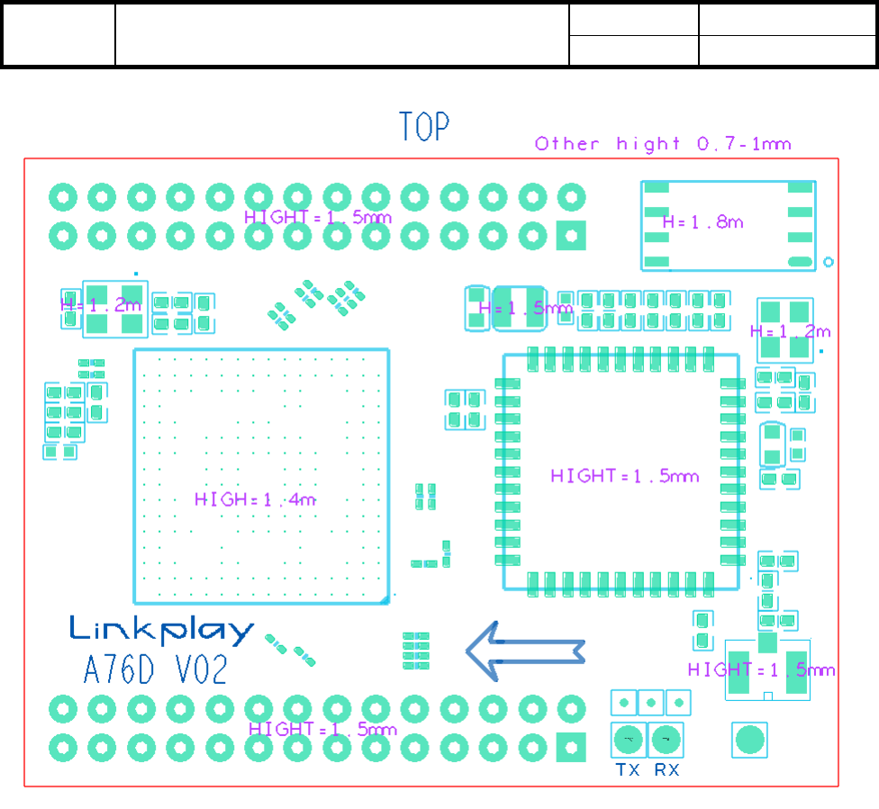
Linkplay A76 module has the dimension of 41.7mm x 32.2mm. The detailed layout will be given shortly below.
Unit: mm

Doc Title Linkplay WiFiAudio-A76 Specification Number WMB20170117
Version 1.2
Document No.: WMB20170117 Page 9 of 21
TOP Components High Limit
Doc Title Linkplay WiFiAudio-A76 Specification Number WMB20170117
Version 1.2
Document No.: WMB20170117 Page 10 of 21
BOTTOM Components High Limit

Doc Title Linkplay WiFiAudio-A76 Specification Number WMB20170117
Version 1.2
Document No.: WMB20170117 Page 11 of 21
Figure 2-2: Linkplay A76 physical dimension
2.3.
External Antenna
A76 uses the external antenna for the best Wi-Fi performance. To use external antenna, please choose the antenna
type that meets the requirement of IEEE 802 b/g/n Wi-Fi standard running at 2.4GHz frequency. The detailed
parameters are shown in the table below.
Item Parameter
Frequency range 2.4~2.5GHz
Impedance 50 Ohm
VSWR 2 (Max)
Reflection loss -10dB (Max)
Connector I-PEX or populate directly
Table 2-5 External antenna parameters for A76
Doc Title Linkplay WiFiAudio-A76 Specification Number WMB20170117
Version 1.2
Document No.: WMB20170117 Page 12 of 21
2.4.
Typical Application
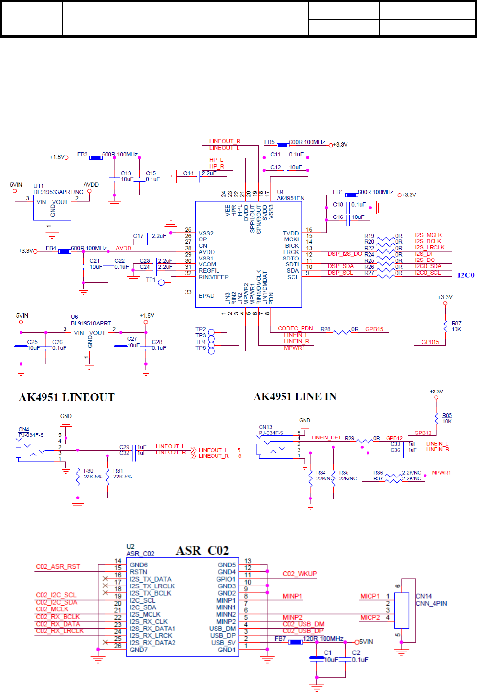
WiFiAudio-A76’s typical reference design:
CODEC
Far-Field

Doc Title Linkplay WiFiAudio-A76 Specification Number WMB20170117
Version 1.2
Document No.: WMB20170117 Page 13 of 21
Micro SD Card
Power

Doc Title Linkplay WiFiAudio-A76 Specification Number WMB20170117
Version 1.2
Document No.: WMB20170117 Page 14 of 21
Button and LED

Doc Title Linkplay WiFiAudio-A76 Specification Number WMB20170117
Version 1.2
Document No.: WMB20170117 Page 15 of 21
2.5 Power on Sequence
A76 module has two power domains: VDDRTC and 5VIN. The following is recommended power on sequence.
There are three I/O pins in RTC power domain:
1. PPRST_N: Power on reset and hardware reset signal input
2. WKUP_N: Power on signal input
3. PWRON: Power on signal output to turn on DCDC/LDO/Power switches
Note: There is an R-C delay circuit on A76 for power on reset sequence, so you may consider PPRSET_N only as
HW reset.
The following are two power on sequences for typical applications

Doc Title Linkplay WiFiAudio-A76 Specification Number WMB20170117
Version 1.2
Document No.: WMB20170117 Page 16 of 21
Power on Sequence #1:
Step 1: Input 1.8V~3.3V power from DC IN or Battery to “VDDRTC” pin, then RTC power domain turns active
Step 2: Input a pulse (low level active, more than 160ms) to “WKUP_N” pin
Step 3: Once A76 gets this pulse , it will continuously output a high level signal from PWNON pin to turn on every
DCDC/LDO
Step 4: DCDC on, 5V power supply to A76 5VIN pin
Step 5:A76 generate every power voltage needed inside the module
Step 6:A76 generate power-on reset inside the module, system boot up

Doc Title Linkplay WiFiAudio-A76 Specification Number WMB20170117
Version 1.2
Document No.: WMB20170117 Page 17 of 21
Power on sequence #2: (Apply to the user case that there is external MCU in the system)
Step 1: MCU turn on the DC/DC and 5V power supply to A76 through “5VIN”
Step 2:A76 generate every power voltage needed inside the module.
Step3:A76 generate power-on reset inside the module and system boot up.
Note 1: Once 5VIN power is stable, current drain from “VDDRTC” pin is no longer exist, A76 will generate a
voltage supply to VDDRTC power domain itself, on purpose of reducing power consumption of RTC battery.
Note 2: During the process of system power-on, every signal connected to A76(I2S,I2C,GPIO,UART etc..) should
configured as GPIO and set to High-Z or input mode. Please strictly avoid high level signals on these traces,
otherwise it may cause wrong power sequence and system boot up failed.
2.6 USB Host Port
Please follow the design rule below to populate the USB host interface:
Item Parameter
Signal Group USB
Topology Differential Pair Point-to-Point
Reference Plane Ground Referenced
Characteristic Trace Impedance (Zo) 90 Ω ±10%

Doc Title Linkplay WiFiAudio-A76 Specification Number WMB20170117
Version 1.2
Document No.: WMB20170117 Page 18 of 21
Trace Width 4 mils
Serpentine Spacing(center to center) 8.5 mils
Minimum Isolation Spacing to Clock Signals 50 mils
Minimum Isolation Spacing to Low-Speed Signals 20 mils
Minimum Isolation Spacing to other USB Pair 20 mils
Total Length (with package length) < 8000 mils
Maximum Recommended Via Count 2 (per side)
DM to DP Length Matching(with package length) Match total length to within ±10 mils
Table 2-2 A76 USB design rule
3. Electrical Specifications
3.1. Absolute Maximum Ratings
The absolute maximum ratings for the processors are listed in Table 3-1. Do not exceed these parameters or the part
may be damaged permanently. Operation at absolute maximum ratings is not guaranteed.
Table 3-1 Absolute Maximum Ratings
Parameter Min Max Unit
Storage Temperature -40 135 ℃
Operation Temperature -5 40 ℃
5VIN power supplies voltage -0.5 5.3 V
Input voltage to VDDRTC supplied non-supply pins -0.5 3.6 V
Maximum ESD stress voltage, Human Body Model; Any
pin to any supply pin, either polarity, or Any pin to all
non-supply pins together, either polarity. Three stresses
maximum.
2000 V
3.2. Recommended operating conditions
The recommended operating conditions are listed in Table 3-2.
Table 3-2 Recommended operating conditions for power supplies
Symbol Description Min Typical Max Unit
5VIN Power supply input 3.7 5.0 5.25 V
VDDRTC RTC power supply input 3.0 3.3 3.6 V

Doc Title Linkplay WiFiAudio-A76 Specification Number WMB20170117
Version 1.2
Document No.: WMB20170117 Page 19 of 21
3.3 Power consumption
The consumption of various operating conditions are listed in Table 3-3.
Table 3-3 Operating conditions for power consumption
Mode Power Unit
Function on Connected w/o data transmission Data transmission
BLE on only 58-61 58-64 58-62 mA
A2DP on only 58-60 57-60 66-70 mA
BLE+A2DP ON 57-61 58-63 67-70 mA
BLE+A2DP off 57-60 mA
Wi-Fi ON 99-111
(Soft AP) 63-109 65-115 mA
Wi-Fi off 60 mA
Hibernation 3 mA
3. Software Introduction
3.1. Feature list
• “Easy Setup”to setup your network, with the help of one button of your device, you can connect the device
to your home router quickly.
• Music stream protocol
Support Spotify Connect, Airplay, DLNA and QPlay protocol
• Amazon Alexa
• Music content
Support iHeartRadio, Napster/Rhapsody, Tidal, Deezer, vTune, Qobuz, Audible, Radio.de, NPR,Ximalaya,
Qingting FM, QQ FM, Douban FM inside, with the help of App, you can search, stream, playback and preset
the musics of the above music services.
• Multiroom
Support multiroom.
Support Airplay, Spotify, Bluetooth, Aux-in multiroom playback.
• Music format
HTTP/HTTPS/RTSP/MMS/TS protocol
HLS/ASX/M3U playlist format
MP3/AAC/FLAC/ALAC/WMA/APE/OGG codec
• BT
Support 4.2:A2DP, AVRCP, HFP, HID profiles
Support BLE

Doc Title Linkplay WiFiAudio-A76 Specification Number WMB20170117
Version 1.2
Document No.: WMB20170117 Page 20 of 21
Support EDR
• Preset
With the help of App, you can store the music account token and playlist in the A76. Then the end user can
play the playlist by the button/voice or timer even without the App.
3.2. App support
• iOS App
>= iOS6.1,suggest iOS10 and above
• Android App
>= Android 4.3.3
• Quick custimzation
With the help of the Linkplay compile server, you can change the brand and some strings, change the logo and
some pictures to get a customization App.
3.3. Certifications
Linkplay can help you to finish follow certifications::
• Wi-Fi Logo
• BQB
• Amazon Alexa
• MFI
• Spotify Connect
• DLNA
• QPlay
4. Module picture and package
1)A76 module picture (insert later)
Notes:
Linkplay: Linkplay logo
A76: Module No.
V01: MP version of A76 module
2)Delivery

Doc Title Linkplay WiFiAudio-A76 Specification Number WMB20170117
Version 1.2
Document No.: WMB20170117 Page 21 of 21
Notes:
One tray = 30pcs
One box = 15 trays
On box in total: 15*30pcs = 450pcs
FCC Radiation Exposure Statement:
This equipment complies with FCC radiation exposure limits set forth for an uncontrolled
environment. End users must follow the specific operating instructions for satisfying RF exposure
compliance.
Note 1: This module certified that complies with RF exposure requirement under mobile or fixed
condition, this module is to be installed only in mobile or fixed applications.
A mobile device is defined as a transmitting device designed to be used in other than fixed
locations and to generally be used in such a way that a separation distance of at least 20
centimeters is normally maintained between the transmitter's radiating structure(s) and the body of
the user or nearby persons. Transmitting devices designed to be used by consumers or workers that
can be easily re-located, such as wireless devices associated with a personal computer, are
considered to be mobile devices if they meet the 20 centimeter separation requirement.
A fixed device is defined as a device is physically secured at one location and is not able to be
easily moved to another location.
Note 2: Any modifications made to the module will void the Grant of Certification, this module is
limited to OEM installation only and must not be sold to end-users, end-user has no manual
instructions to remove or install the device, only software or operating procedure shall be placed
in the end-user operating manual of final products.
Note 3: Additional testing and certification may be necessary when multiple modules are used.
Note 4: The module may be operated only with the antenna with which it is authorized. Any
antenna that is of the same type and of equal or less directional gain as an antenna that is
authorized with the intentional radiator may be marketed with, and used with, that intentional
radiator.
Note 5: To ensure compliance with all non-transmitter functions the host manufacturer is
responsible for ensuring compliance with the module(s) installed and fully operational. For
example, if a host was previously authorized as an unintentional radiator under the Declaration of
Conformity procedure without a transmitter certified module and a module is added, the host
manufacturer is responsible for ensuring that the after the module is installed and operational the
host continues to be compliant with the Part 15B unintentional radiator requirements. Since this
may depend on the details of how the module is integrated with the host, Linkplay Technology
Inc.. shall provide guidance to the host manufacturer for compliance with the Part 15B
requirements.
Note 6: FCC ID label on the final system must be labeled with “Contains FCC ID: 2ANOG-A76D”
or “Contains transmitter module FCC ID: 2ANOG-A76D”.
FCC Warning
This device complies with Part 15 of the FCC Rules. Operation is subject to the following two
conditions:
(1) This device may not cause harmful interference, and (2) this device must accept any
interference received, including interference that may cause undesired operation.
NOTE: Any changes or modifications to this unit not expressly approved by the party responsible
for compliance could void the user's authority to operate the equipment.
IC WARNING
This device complies with Industry Canada’s licence-exempt RSSs. Operation is subject to the
following two conditions:
(1) This device may not cause interference; and
(2) This device must accept any interference, including interference that may cause undesired
operation of the device.
Le présent appareil est conforme aux CNR d'Industrie Canada applicables aux appareils radio
exempts de licence. L'exploitation est autorisée aux deux conditions suivantes: (1) l'appareil ne
doit pas produire de brouillage, et (2) l'utilisateur de l'appareil doit accepter tout brouillage
radioélectrique subi, même si le brouillage est susceptible d'en compromettre le fonctionnement.
IC Radiation Exposure Statement:
This module and its antenna(s) must not be co-located with any other transmitters except in
accordance with IC multi-transmitter product procedures. Referring to the multi-transmitter policy,
multiple-transmitter(s) and module(s) can be operated simultaneously without reassessment
permissive change.
Cet appareil et son antenne (s) ne doit pas être co-localisés ou fonctionnement en association avec
une autre antenne ou transmetteur.
This equipment complies with IC RSS-102 radiation exposure limits set forth for an uncontrolled
environment. This equipment should be installed and operated with minimum distance 20cm
between the radiator & your body.
Cet équipement est conforme aux limites d'exposition aux rayonnements IC établies pour un
environnement non contrôlé. Cet équipement doit être installé et utilisé avec un minimum de
20cm de distance entre la source de rayonnement et votre corps.
This module is limited to OEM installation only and must not be sold to end-users, end-user has
no manual instructions to remove or install the device, only software or operating procedure shall
be placed in the end-user operating manual of final products. Additional testing and certification
may be necessary when multiple modules are used.
Any changes or modifications not expressly approved by the manufacturer could void the user's
authority to operate this equipment.
The final end product must be labeled in a visible area with the following " Contains IC:
23153-A76F ".