Linksys Business Series Srw2016 Users Manual Cisco SRW2048, SRW2024, SRW2016, SRW248G4, SRW224G4 WebView Switches Administration Guide
SRW2024 to the manual 7374c104-7e40-4d83-8c71-b9c0f21fcd05
2015-03-12
: Linksys Linksys-Business-Series-Srw2016-Users-Manual-657713 linksys-business-series-srw2016-users-manual-657713 linksys pdf
Open the PDF directly: View PDF ![]() .
.
Page Count: 96
- Chapter 1: Introduction
- Chapter 2: Product Overview
- Chapter 3: Connecting the Switch
- Chapter 4: Configuration Using the Console Interface
- Chapter 5: Advanced Configuration
- Overview
- Accessing the Web-based Utility
- Setup > Summary
- Setup > Network Settings
- Setup > Time
- Setup > Green Ethernet
- Port Management > Port Settings
- Port Management > Link Aggregation
- Port Management > LACP
- VLAN Management > Create VLAN
- VLAN Management > Port Setting
- VLAN Management > Ports to VLAN
- VLAN Management > VLAN to Ports
- VLAN Management > GVRP
- Statistics > RMON Statistics
- Statistics > RMON History
- Statistics > RMON Alarm
- Statistics > RMON Events
- Statistics > Port Utilization
- Statistics > 802.1x Statistics
- Statistics > GVRP Statistics
- ACL > IP Based ACL
- ACL > MAC Based ACL
- Security > ACL Binding
- Security > RADIUS
- Security > TACACS+
- Security > 802.1x Settings
- Security > Port Security
- Security > Multiple Hosts
- Security > Storm Control
- QoS
- QoS > CoS Settings
- QoS > Queue Settings
- QoS > DSCP Settings
- QoS > Bandwidth
- QoS > Basic Mode
- QoS > Advanced Mode
- Spanning Tree
- Spanning Tree > STP Status
- Spanning Tree > Global STP
- Spanning Tree > STP Port Settings
- Spanning Tree > RSTP Port Settings
- Spanning Tree > MSTP Properties
- Spanning Tree > MSTP Instance Settings
- Spanning Tree > MSTP Interface Settings
- Multicast > IGMP Snooping
- Multicast > Bridge Multicast
- Multicast > Bridge Multicast Forward All
- SNMP > Global Parameters
- SNMP > Views
- SNMP > Group Profile
- SNMP > Group Membership
- SNMP > Communities
- SNMP > Notification Filter
- SNMP > Notification Recipient
- Admin > User Authentication
- Admin > Jumbo Frames
- Admin > Static Address
- Admin > Dynamic Address
- Admin > Logging
- Admin > Port Mirroring
- Admin > Cable Test
- Admin > Save Configuration
- Admin > Firmware Upgrade
- Admin > Reboot
- Admin > Factory Defaults
- Admin > Server Logs
- Admin > Memory Logs
- Admin > Flash Logs
- Appendix A: About Gigabit Ethernet and Fiber Optic Cabling
- Appendix B: Windows Help
- Appendix C: Downloading using Xmodem
- Appendix D: Glossary
- Appendix E: Specifications
- Appendix F: Warranty Information
- Appendix G: Regulatory Information
- Appendix H: Software License Agreement
- Appendix I: Contact Information
USER GUIDE
BUSINESS SERIES
WebView Switches
Model: SRW2048, SRW2024, SRW2016, SRW248G4, SRW224G4
ii
About This Guide
WebView Switches
About This Guide
Icon Descriptions
While reading through the User Guide you may see
various icons that call attention to specific items. Below is
a description of these icons:
NOTE: This check mark indicates that there is
a note of interest and is something that you
should pay special attention to while using the
product.
WARNING: This exclamation point indicates
that there is a caution or warning and it is
something that could damage your property or
product.
WEB: This globe icon indicates a noteworthy
website address or e-mail address.
Online Resources
Website addresses in this document are listed without
http:// in front of the address because most current web
browsers do not require it. If you use an older web browser,
you may have to add http:// in front of the web address.
Resource Website
Linksys www.linksys.com
Linksys International www.linksys.com/international
Glossary www.linksys.com/glossary
Network Security www.linksys.com/security
Copyright and Trademarks
Linksys is a registered trademark or
trademark of Cisco Systems, Inc. and/
or its affiliates in the U.S. and certain
other countries. Copyright © 2008
Cisco Systems, Inc. All rights reserved.
Other brands and product names are
trademarks or registered trademarks
of their respective holders.

i
Table of Contents
WebView Switches
Chapter 1: Introduction 1
Chapter 2: Product Overview 2
SRW2048 . . . . . . . . . . . . . . . . . . . . . . . . . . . . . . . . . . . . . . . . . . . . . . . . . . . 2
Front Panel. . . . . . . . . . . . . . . . . . . . . . . . . . . . . . . . . . . . . . . . . . . . . . . 2
LEDs . . . . . . . . . . . . . . . . . . . . . . . . . . . . . . . . . . . . . . . . . . . . . . . . . . . 2
Back Panel . . . . . . . . . . . . . . . . . . . . . . . . . . . . . . . . . . . . . . . . . . . . . . . 2
SRW2024 . . . . . . . . . . . . . . . . . . . . . . . . . . . . . . . . . . . . . . . . . . . . . . . . . . . 3
Front Panel. . . . . . . . . . . . . . . . . . . . . . . . . . . . . . . . . . . . . . . . . . . . . . . 3
LEDs . . . . . . . . . . . . . . . . . . . . . . . . . . . . . . . . . . . . . . . . . . . . . . . . . . . 3
Back Panel . . . . . . . . . . . . . . . . . . . . . . . . . . . . . . . . . . . . . . . . . . . . . . . 3
SRW2016 . . . . . . . . . . . . . . . . . . . . . . . . . . . . . . . . . . . . . . . . . . . . . . . . . . . 4
Front Panel. . . . . . . . . . . . . . . . . . . . . . . . . . . . . . . . . . . . . . . . . . . . . . . 4
LEDs . . . . . . . . . . . . . . . . . . . . . . . . . . . . . . . . . . . . . . . . . . . . . . . . . . . 4
The Back Panel . . . . . . . . . . . . . . . . . . . . . . . . . . . . . . . . . . . . . . . . . . . . 4
SRW248G4 . . . . . . . . . . . . . . . . . . . . . . . . . . . . . . . . . . . . . . . . . . . . . . . . . . 5
Front Panel. . . . . . . . . . . . . . . . . . . . . . . . . . . . . . . . . . . . . . . . . . . . . . . 5
LEDs . . . . . . . . . . . . . . . . . . . . . . . . . . . . . . . . . . . . . . . . . . . . . . . . . . . 5
Back Panel . . . . . . . . . . . . . . . . . . . . . . . . . . . . . . . . . . . . . . . . . . . . . . . 5
SRW224G4 . . . . . . . . . . . . . . . . . . . . . . . . . . . . . . . . . . . . . . . . . . . . . . . . . . 6
Front Panel. . . . . . . . . . . . . . . . . . . . . . . . . . . . . . . . . . . . . . . . . . . . . . . 6
LEDs . . . . . . . . . . . . . . . . . . . . . . . . . . . . . . . . . . . . . . . . . . . . . . . . . . . 6
Back Panel . . . . . . . . . . . . . . . . . . . . . . . . . . . . . . . . . . . . . . . . . . . . . . . 6
Chapter 3: Connecting the Switch 8
Overview. . . . . . . . . . . . . . . . . . . . . . . . . . . . . . . . . . . . . . . . . . . . . . . . . . . 8
Placement Options . . . . . . . . . . . . . . . . . . . . . . . . . . . . . . . . . . . . . . . . . . . . 8
Desktop Placement . . . . . . . . . . . . . . . . . . . . . . . . . . . . . . . . . . . . . . . . . 8
Rack-Mount Placement . . . . . . . . . . . . . . . . . . . . . . . . . . . . . . . . . . . . . . . 8
Hardware Installation . . . . . . . . . . . . . . . . . . . . . . . . . . . . . . . . . . . . . . . . . . . 9
Configuring the Switch . . . . . . . . . . . . . . . . . . . . . . . . . . . . . . . . . . . . . . . . . . 9
Chapter 4: Conguration Using the Console Interface 10
Overview. . . . . . . . . . . . . . . . . . . . . . . . . . . . . . . . . . . . . . . . . . . . . . . . . . .10
Configuring the HyperTerminal Application. . . . . . . . . . . . . . . . . . . . . . . . . . . . .10
Connecting to the Switch through a Telnet Session . . . . . . . . . . . . . . . . . . . . . . . .10
Configuring the Switch through the Console Interface. . . . . . . . . . . . . . . . . . . . . .11
Switch Main Menu . . . . . . . . . . . . . . . . . . . . . . . . . . . . . . . . . . . . . . . . . . . . .11
System Configuration Menu . . . . . . . . . . . . . . . . . . . . . . . . . . . . . . . . . . . .11
Port Status . . . . . . . . . . . . . . . . . . . . . . . . . . . . . . . . . . . . . . . . . . . . . . .18
Port Configuration . . . . . . . . . . . . . . . . . . . . . . . . . . . . . . . . . . . . . . . . . .19
Help . . . . . . . . . . . . . . . . . . . . . . . . . . . . . . . . . . . . . . . . . . . . . . . . . . .19

ii
Table of Contents
WebView Switches
Chapter 5: Advanced Conguration 20
Overview. . . . . . . . . . . . . . . . . . . . . . . . . . . . . . . . . . . . . . . . . . . . . . . . . . .20
Accessing the Web-based Utility . . . . . . . . . . . . . . . . . . . . . . . . . . . . . . . . . . . .20
Setup > Summary . . . . . . . . . . . . . . . . . . . . . . . . . . . . . . . . . . . . . . . . . . . . .20
Device Information . . . . . . . . . . . . . . . . . . . . . . . . . . . . . . . . . . . . . . . . .20
System Information . . . . . . . . . . . . . . . . . . . . . . . . . . . . . . . . . . . . . . . . .21
Setup > Network Settings . . . . . . . . . . . . . . . . . . . . . . . . . . . . . . . . . . . . . . . .21
Identification . . . . . . . . . . . . . . . . . . . . . . . . . . . . . . . . . . . . . . . . . . . . .21
IP Configuration . . . . . . . . . . . . . . . . . . . . . . . . . . . . . . . . . . . . . . . . . . .21
Setup > Time . . . . . . . . . . . . . . . . . . . . . . . . . . . . . . . . . . . . . . . . . . . . . . . .22
Set Time. . . . . . . . . . . . . . . . . . . . . . . . . . . . . . . . . . . . . . . . . . . . . . . . .22
Local Time . . . . . . . . . . . . . . . . . . . . . . . . . . . . . . . . . . . . . . . . . . . . . . .22
Daylight Saving . . . . . . . . . . . . . . . . . . . . . . . . . . . . . . . . . . . . . . . . . . . .22
SNTP Servers. . . . . . . . . . . . . . . . . . . . . . . . . . . . . . . . . . . . . . . . . . . . . .22
Setup > Green Ethernet . . . . . . . . . . . . . . . . . . . . . . . . . . . . . . . . . . . . . . . . .23
Port Management > Port Settings . . . . . . . . . . . . . . . . . . . . . . . . . . . . . . . . . . .23
Port Settings > Port Configuration . . . . . . . . . . . . . . . . . . . . . . . . . . . . . . . .24
Port Management > Link Aggregation . . . . . . . . . . . . . . . . . . . . . . . . . . . . . . . .25
Link Aggregation > Detail . . . . . . . . . . . . . . . . . . . . . . . . . . . . . . . . . . . . .25
Port Management > LACP . . . . . . . . . . . . . . . . . . . . . . . . . . . . . . . . . . . . . . . .26
VLAN Management > Create VLAN . . . . . . . . . . . . . . . . . . . . . . . . . . . . . . . . . .26
Single VLAN . . . . . . . . . . . . . . . . . . . . . . . . . . . . . . . . . . . . . . . . . . . . . .26
VLAN Range . . . . . . . . . . . . . . . . . . . . . . . . . . . . . . . . . . . . . . . . . . . . . .26
VLAN Table . . . . . . . . . . . . . . . . . . . . . . . . . . . . . . . . . . . . . . . . . . . . . . .26
VLAN Management > Port Setting. . . . . . . . . . . . . . . . . . . . . . . . . . . . . . . . . . .27
VLAN Management > Ports to VLAN . . . . . . . . . . . . . . . . . . . . . . . . . . . . . . . . .27
VLAN Management > VLAN to Ports . . . . . . . . . . . . . . . . . . . . . . . . . . . . . . . . .28
VLAN Management > GVRP . . . . . . . . . . . . . . . . . . . . . . . . . . . . . . . . . . . . . . .28
Statistics > RMON Statistics . . . . . . . . . . . . . . . . . . . . . . . . . . . . . . . . . . . . . . .29
Statistics > RMON History . . . . . . . . . . . . . . . . . . . . . . . . . . . . . . . . . . . . . . . .30
Log Table . . . . . . . . . . . . . . . . . . . . . . . . . . . . . . . . . . . . . . . . . . . . . . . .30
RMON History . . . . . . . . . . . . . . . . . . . . . . . . . . . . . . . . . . . . . . . . . . . . .30
Statistics > RMON Alarm . . . . . . . . . . . . . . . . . . . . . . . . . . . . . . . . . . . . . . . . .31
Statistics > RMON Events. . . . . . . . . . . . . . . . . . . . . . . . . . . . . . . . . . . . . . . . .32
Add Event . . . . . . . . . . . . . . . . . . . . . . . . . . . . . . . . . . . . . . . . . . . . . . .32
RMON Events Log . . . . . . . . . . . . . . . . . . . . . . . . . . . . . . . . . . . . . . . . . .32
Statistics > Port Utilization . . . . . . . . . . . . . . . . . . . . . . . . . . . . . . . . . . . . . . . .32
Statistics > 802.1x Statistics . . . . . . . . . . . . . . . . . . . . . . . . . . . . . . . . . . . . . . .33
Statistics > GVRP Statistics . . . . . . . . . . . . . . . . . . . . . . . . . . . . . . . . . . . . . . . .33
ACL > IP Based ACL . . . . . . . . . . . . . . . . . . . . . . . . . . . . . . . . . . . . . . . . . . . .34
ACL > MAC Based ACL . . . . . . . . . . . . . . . . . . . . . . . . . . . . . . . . . . . . . . . . . .35
Security > ACL Binding . . . . . . . . . . . . . . . . . . . . . . . . . . . . . . . . . . . . . . . . . .36

iii
Table of Contents
WebView Switches
Security > RADIUS . . . . . . . . . . . . . . . . . . . . . . . . . . . . . . . . . . . . . . . . . . . . .36
Security > TACACS+ . . . . . . . . . . . . . . . . . . . . . . . . . . . . . . . . . . . . . . . . . . . .37
Security > 802.1x Settings . . . . . . . . . . . . . . . . . . . . . . . . . . . . . . . . . . . . . . . .37
802.1x Settings > Setting Timer. . . . . . . . . . . . . . . . . . . . . . . . . . . . . . . . . .38
Security > Port Security. . . . . . . . . . . . . . . . . . . . . . . . . . . . . . . . . . . . . . . . . .38
Security > Multiple Hosts. . . . . . . . . . . . . . . . . . . . . . . . . . . . . . . . . . . . . . . . .39
Security > Storm Control . . . . . . . . . . . . . . . . . . . . . . . . . . . . . . . . . . . . . . . . .40
QoS . . . . . . . . . . . . . . . . . . . . . . . . . . . . . . . . . . . . . . . . . . . . . . . . . . . . . .40
QoS > CoS Settings . . . . . . . . . . . . . . . . . . . . . . . . . . . . . . . . . . . . . . . . . . . .40
CoS Default . . . . . . . . . . . . . . . . . . . . . . . . . . . . . . . . . . . . . . . . . . . . . .41
QoS > Queue Settings . . . . . . . . . . . . . . . . . . . . . . . . . . . . . . . . . . . . . . . . . .41
QoS > DSCP Settings . . . . . . . . . . . . . . . . . . . . . . . . . . . . . . . . . . . . . . . . . . .41
QoS > Bandwidth . . . . . . . . . . . . . . . . . . . . . . . . . . . . . . . . . . . . . . . . . . . . .41
QoS > Basic Mode . . . . . . . . . . . . . . . . . . . . . . . . . . . . . . . . . . . . . . . . . . . . .42
QoS > Advanced Mode . . . . . . . . . . . . . . . . . . . . . . . . . . . . . . . . . . . . . . . . . .42
Advanced Mode > Out of Profile DSCP . . . . . . . . . . . . . . . . . . . . . . . . . . . . .42
Advanced Mode > Policy Name. . . . . . . . . . . . . . . . . . . . . . . . . . . . . . . . . .43
Advanced Mode > New Class Map . . . . . . . . . . . . . . . . . . . . . . . . . . . . . . . .43
Advanced Mode > New Aggregate Policer. . . . . . . . . . . . . . . . . . . . . . . . . . .43
Spanning Tree. . . . . . . . . . . . . . . . . . . . . . . . . . . . . . . . . . . . . . . . . . . . . . . .43
Spanning Tree > STP Status . . . . . . . . . . . . . . . . . . . . . . . . . . . . . . . . . . . . . . .44
Spanning Tree > Global STP . . . . . . . . . . . . . . . . . . . . . . . . . . . . . . . . . . . . . . .44
Global Setting . . . . . . . . . . . . . . . . . . . . . . . . . . . . . . . . . . . . . . . . . . . . .44
Bridge Settings . . . . . . . . . . . . . . . . . . . . . . . . . . . . . . . . . . . . . . . . . . . .45
Spanning Tree > STP Port Settings . . . . . . . . . . . . . . . . . . . . . . . . . . . . . . . . . . .45
Spanning Tree > RSTP Port Settings . . . . . . . . . . . . . . . . . . . . . . . . . . . . . . . . . .46
Spanning Tree > MSTP Properties . . . . . . . . . . . . . . . . . . . . . . . . . . . . . . . . . . .47
Spanning Tree > MSTP Instance Settings. . . . . . . . . . . . . . . . . . . . . . . . . . . . . . .48
Spanning Tree > MSTP Interface Settings . . . . . . . . . . . . . . . . . . . . . . . . . . . . . .48
Multicast > IGMP Snooping . . . . . . . . . . . . . . . . . . . . . . . . . . . . . . . . . . . . . . .49
Multicast > Bridge Multicast. . . . . . . . . . . . . . . . . . . . . . . . . . . . . . . . . . . . . . .50
Multicast > Bridge Multicast Forward All . . . . . . . . . . . . . . . . . . . . . . . . . . . . . . .50
SNMP > Global Parameters . . . . . . . . . . . . . . . . . . . . . . . . . . . . . . . . . . . . . . .51
SNMP > Views. . . . . . . . . . . . . . . . . . . . . . . . . . . . . . . . . . . . . . . . . . . . . . . .51
SNMP > Group Profile . . . . . . . . . . . . . . . . . . . . . . . . . . . . . . . . . . . . . . . . . . .52
SNMP > Group Membership. . . . . . . . . . . . . . . . . . . . . . . . . . . . . . . . . . . . . . .52
SNMP > Communities. . . . . . . . . . . . . . . . . . . . . . . . . . . . . . . . . . . . . . . . . . .53
Base Table . . . . . . . . . . . . . . . . . . . . . . . . . . . . . . . . . . . . . . . . . . . . . . .54
Advanced Table . . . . . . . . . . . . . . . . . . . . . . . . . . . . . . . . . . . . . . . . . . . .54
SNMP > Notification Filter . . . . . . . . . . . . . . . . . . . . . . . . . . . . . . . . . . . . . . . .54
SNMP > Notification Recipient . . . . . . . . . . . . . . . . . . . . . . . . . . . . . . . . . . . . .55
Admin > User Authentication . . . . . . . . . . . . . . . . . . . . . . . . . . . . . . . . . . . . . .55
Admin > Jumbo Frames . . . . . . . . . . . . . . . . . . . . . . . . . . . . . . . . . . . . . . . . .56

iv
Table of Contents
WebView Switches
Admin > Static Address. . . . . . . . . . . . . . . . . . . . . . . . . . . . . . . . . . . . . . . . . .56
Query . . . . . . . . . . . . . . . . . . . . . . . . . . . . . . . . . . . . . . . . . . . . . . . . . .56
Admin > Dynamic Address . . . . . . . . . . . . . . . . . . . . . . . . . . . . . . . . . . . . . . .57
Query . . . . . . . . . . . . . . . . . . . . . . . . . . . . . . . . . . . . . . . . . . . . . . . . . .57
Admin > Logging . . . . . . . . . . . . . . . . . . . . . . . . . . . . . . . . . . . . . . . . . . . . .57
Admin > Port Mirroring. . . . . . . . . . . . . . . . . . . . . . . . . . . . . . . . . . . . . . . . . .58
Admin > Cable Test . . . . . . . . . . . . . . . . . . . . . . . . . . . . . . . . . . . . . . . . . . . .58
Admin > Save Configuration . . . . . . . . . . . . . . . . . . . . . . . . . . . . . . . . . . . . . .59
Via TFTP. . . . . . . . . . . . . . . . . . . . . . . . . . . . . . . . . . . . . . . . . . . . . . . . .59
Via HTTP . . . . . . . . . . . . . . . . . . . . . . . . . . . . . . . . . . . . . . . . . . . . . . . .59
Backup . . . . . . . . . . . . . . . . . . . . . . . . . . . . . . . . . . . . . . . . . . . . . . . . .59
Admin > Firmware Upgrade . . . . . . . . . . . . . . . . . . . . . . . . . . . . . . . . . . . . . . .59
Admin > Reboot . . . . . . . . . . . . . . . . . . . . . . . . . . . . . . . . . . . . . . . . . . . . . .60
Admin > Factory Defaults . . . . . . . . . . . . . . . . . . . . . . . . . . . . . . . . . . . . . . . .60
Admin > Server Logs . . . . . . . . . . . . . . . . . . . . . . . . . . . . . . . . . . . . . . . . . . .60
Admin > Memory Logs . . . . . . . . . . . . . . . . . . . . . . . . . . . . . . . . . . . . . . . . . .61
Admin > Flash Logs . . . . . . . . . . . . . . . . . . . . . . . . . . . . . . . . . . . . . . . . . . . .61
Appendix A: About Gigabit Ethernet and Fiber Optic Cabling 62
Gigabit Ethernet . . . . . . . . . . . . . . . . . . . . . . . . . . . . . . . . . . . . . . . . . . . . . .62
Fiber Optic Cabling . . . . . . . . . . . . . . . . . . . . . . . . . . . . . . . . . . . . . . . . . . . .62
Appendix B: Windows Help 63
TCP/IP . . . . . . . . . . . . . . . . . . . . . . . . . . . . . . . . . . . . . . . . . . . . . . . . . . . . .63
Shared Resources . . . . . . . . . . . . . . . . . . . . . . . . . . . . . . . . . . . . . . . . . . . . .63
Network Neighborhood/My Network Places . . . . . . . . . . . . . . . . . . . . . . . . . . . .63
Appendix C: Downloading using Xmodem 64
Startup Menu Procedures . . . . . . . . . . . . . . . . . . . . . . . . . . . . . . . . . . . . . . . .64
Appendix D: Glossary 66
Appendix E: Specications 70
Appendix F: Warranty Information 75
Limited Warranty. . . . . . . . . . . . . . . . . . . . . . . . . . . . . . . . . . . . . . . . . . . . . .75
Exclusions and Limitations. . . . . . . . . . . . . . . . . . . . . . . . . . . . . . . . . . . . . . . .75
Obtaining Warranty Service . . . . . . . . . . . . . . . . . . . . . . . . . . . . . . . . . . . . . . .75
Technical Support . . . . . . . . . . . . . . . . . . . . . . . . . . . . . . . . . . . . . . . . . . . . .76
Appendix G: Regulatory Information 77
FCC Statement . . . . . . . . . . . . . . . . . . . . . . . . . . . . . . . . . . . . . . . . . . . . . . .77
Safety Notices. . . . . . . . . . . . . . . . . . . . . . . . . . . . . . . . . . . . . . . . . . . . . . . .77
Industry Canada Statement . . . . . . . . . . . . . . . . . . . . . . . . . . . . . . . . . . . . . . .77
Avis d’Industrie Canada. . . . . . . . . . . . . . . . . . . . . . . . . . . . . . . . . . . . . . .77

v
Table of Contents
WebView Switches
User Information for Consumer Products Covered by EU Directive 2002/96/EC on Waste
Electric and Electronic Equipment (WEEE) . . . . . . . . . . . . . . . . . . . . . . . . . . . . . .78
Appendix H: Software License Agreement 82
Software in Linksys Products: . . . . . . . . . . . . . . . . . . . . . . . . . . . . . . . . . . . . . .82
Software Licenses: . . . . . . . . . . . . . . . . . . . . . . . . . . . . . . . . . . . . . . . . . . . . .82
Schedule 1 Linksys Software License Agreement. . . . . . . . . . . . . . . . . . . . . . .82
Schedule 2 . . . . . . . . . . . . . . . . . . . . . . . . . . . . . . . . . . . . . . . . . . . . . . .83
Schedule 3 . . . . . . . . . . . . . . . . . . . . . . . . . . . . . . . . . . . . . . . . . . . . . . .86
Appendix I: Contact Information 89

1
Introduction
WebView Switches
Chapter 1
Chapter 1:
Introduction
Thank you for choosing Linksys WebView Switches. This
User Guide covers five product models:
SRW2048 • 48-port 10/100/1000 Gigabit Switch with
WebView. Includes 48 10/100/1000 RJ-45 ports and 4
shared SFP (MiniGBIC) slots.
SRW2024 •24-Port 10/100/1000 Gigabit Switch with
WebView. Includes 24 10/100/1000 RJ-45 ports and 2
shared SFP (MiniGBIC) slots.
SRW2016 •16-Port 10/100/1000 Gigabit Switch with
WebView. Includes 16 10/100/1000 RJ-45 ports and 2
shared SFP (MiniGBIC) slots.
SRW248G4 •48-port 10/100 + 4-Port Gigabit Switch
with WebView. Includes 48 10/100 RJ-45 ports and 4
10/100/1000 RJ-45 ports and 2 shared SFP (MiniGBIC)
slots.
SRW224G4 •24-port 10/100 + 4-Port Gigabit Switch
with WebView Includes 24 10/100 RJ-45 ports and 4
10/100/1000 RJ-45 ports and 2 shared SFP (MiniGBIC)
slots.
For the purpose of this manual, whenever a feature
applies to all models, the name WebView Switch will be
referenced. If a specific model number is mentioned, then
the feature is specific to that model.
The Linksys WebView Managed Switch allows you to
expand your network securely. Configuration of the switch
is secured using SSL for Web access. User control is secured
using 802.1x security using a RADIUS authentication
mechanism and can also be controlled using MAC-based
filtering.
Extensive QoS features makes the solution ideal for real-
time applications like Voice and Video. The 4 priority
queues together with the Weighted Round Robin and
Strict Priority scheduling techniques facilitate efficient
coexistence of real-time traffic with data traffic allowing
them each to meet their QoS needs.
Individual users or applications can be prioritized above
others using various Class of Service options - by port,
layer 2 priority (802.1p), and Layer 3 priority (TOS or
DSCP). Intelligent Broadcast, and Multicast storm control
minimizes and contain the effect of these types of traffic on
regular traffic. IGMP Snooping limits bandwidth-intensive
video traffic to only the requestors without flooding to all
users.
Incoming traffic can be policed and outgoing traffic can
be shaped allowing you to control network access and
traffic flow.
There are features that allow you to expand and grow your
network of switches. Link aggregation allows multiple
high-bandwidth trunks between switches to be setup.
This also provides a level of reliability in that the system
continues to operate if one of the links break. Spanning
Tree (STP), Fast Linkover, Rapid Spanning Tree (RSTP) and
Multiple Spanning Tree (MSTP) allows you to build a mesh
of switches increasing the availability of the system.
The rich management functionality of the WebView
switches includes SNMP, RMON, Telnet, and HTTP
Management options, allowing you to flexibly integrate
and manage these devices in your network.
2
Product Overview
WebView Switches
Chapter 2
Chapter 2:
Product Overview
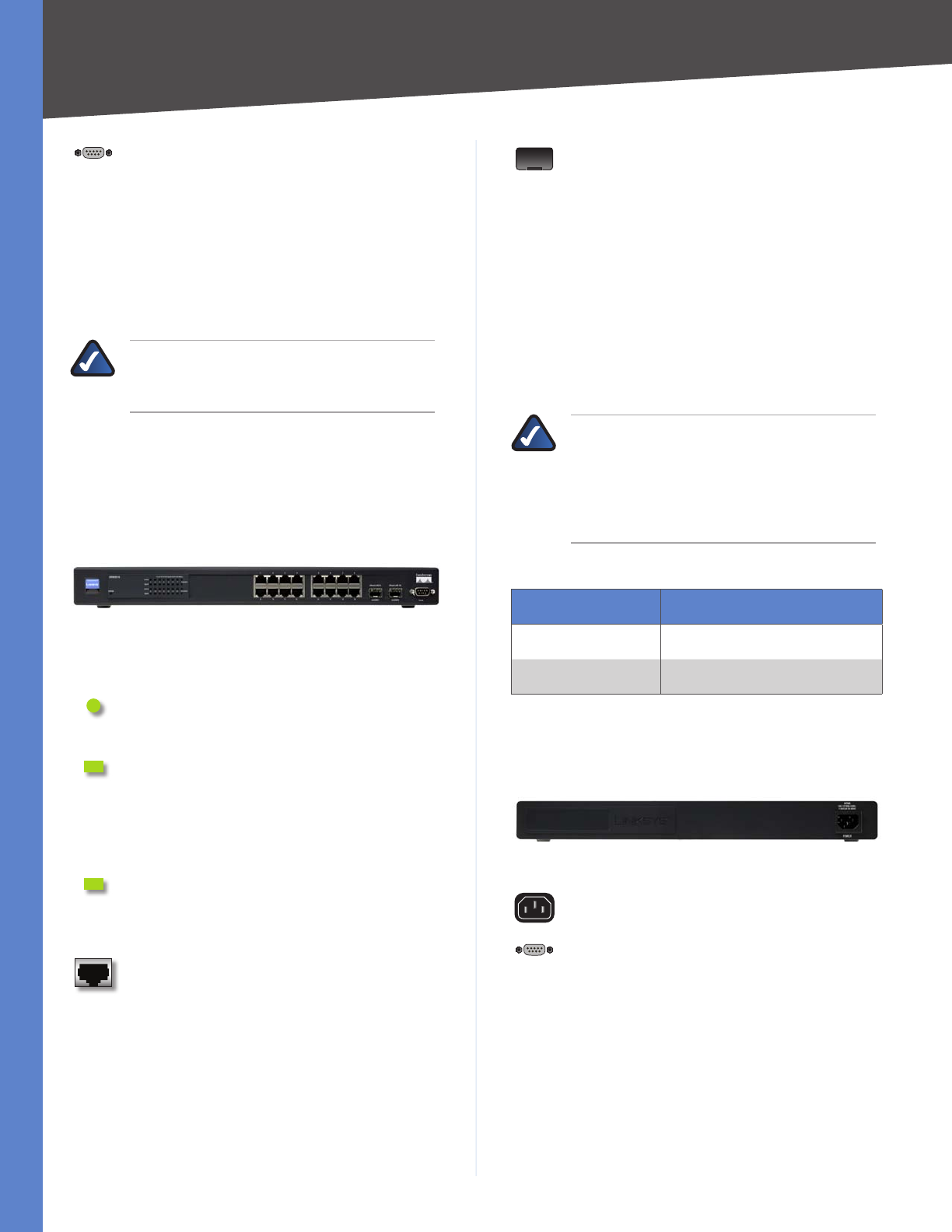
SRW2048
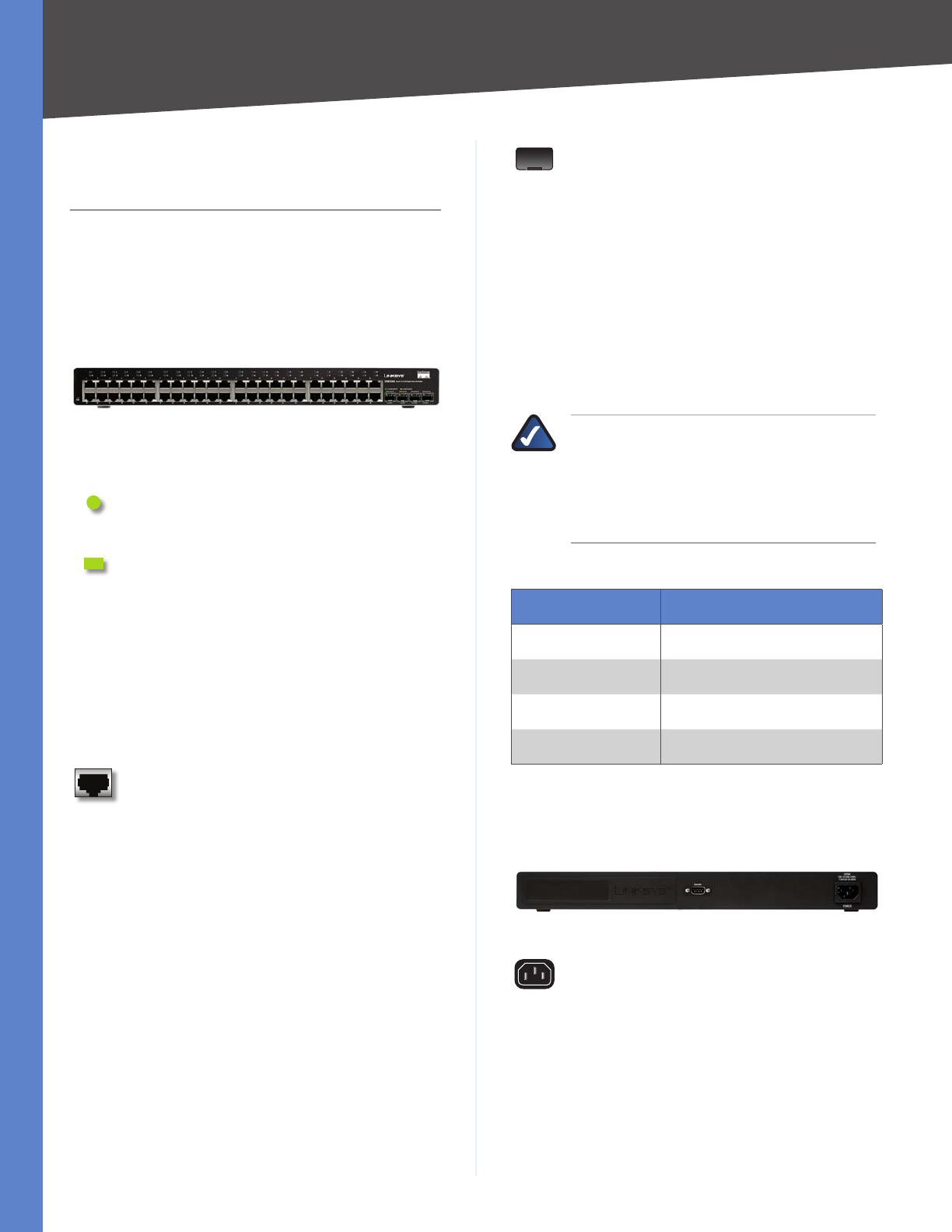
Front Panel
The Switch’s LEDs and ports are located on the front
panel.
Front Panel of the SRW2048
LEDs
POWER (Green) Lights up green to indicate
that power is being supplied to the Switch.
LINK/ACT (1-48) (Green/Amber) Lights up
green to indicate a functional 10/100-Mbps
network link through the corresponding port (1
through 48) with an attached device. It flashes
to indicate that the Switch is actively sending
or receiving data over that port. Lights up
amber to indicate a 1000-Mbps connection on
the corresponding port (1 through 48) with an
attached device. It flashes to indicate that the
Switch is actively sending or receiving data over
that port.
ETHERNET 1-48 The Switch is equipped with
48 auto-sensing, Ethernet network ports, which
use RJ-45 connectors. The Fast Ethernet ports
support network speeds of 10 Mbps, 100 Mbps,
or 1000 Mbps. They can operate in half and
full-duplex modes. Auto-sensing technology
enables each port to automatically detect the
speed of the device connected to it (10 Mbps,
100 Mbps, or 1000 Mbps), and adjust its speed
and duplex accordingly.
MiniGBIC (1-4) The miniGBIC (gigabit interface
converter) port is a connection point for a
miniGBIC expansion module, so the Switch can
be uplinked via fiber to another switch. The
MiniGBIC port provides a link to a high-speed
network segment or individual workstation at
speeds of up to 1000 Mbps.
Use the Linksys MGBT1, MGBSX1, or MGBLH1
miniGBIC modules with the Switch. The
MGBSX1 and the MGBLH1 require fiber cabling
with LC connectors, while the MGBT1 requires
a Category 5e Ethernet cable with an RJ-45
connector.
NOTE: On the SRW2048, MiniGBIC ports are
shared with standard ports. If a miniGBIC port
is used, then the shared standard port on the
Switch cannot be used. The following table
provides port mapping details of the SRW2048
Switch.
SRW2048 Shared Port Mapping
miniGBIC Port Standard Port
miniGBIC 1 Port 23
miniGBIC 2 Port 24
miniGBIC 3 Port 47
miniGBIC 4 Port 48
Back Panel
The power port is located on the back panel of the
Switch.
Back Panel of the SRW2048
POWER The Power port is where you will
connect the AC power.
3
Product Overview
WebView Switches
Chapter 2
CONSOLE The Switch is equipped with a
serial port labeled Console (located on the
back of the switch) that allows you to connect
to a computer’s serial port (for configuration
purposes) using the provided serial cable. You
can use HyperTerminal to manage the Switch
using the console port.
Refer to Chapter 4: Configuration Using the
Console Interface for more information.
NOTE: If you need to reset the Switch, unplug
the power cord from the back of the Switch.
Wait a few seconds and then reconnect it.
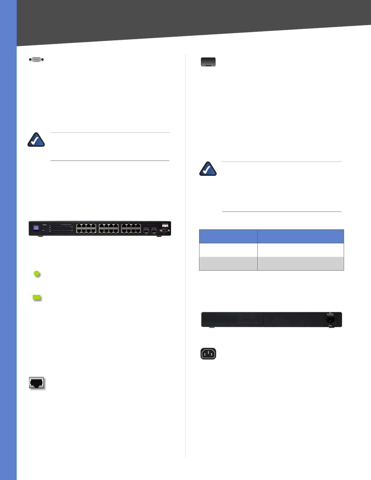
SRW2024
Front Panel
The Switch’s LEDs and ports are located on the front
panel.
Front Panel of the SRW2024
LEDs
POWER (Green) Lights up green to indicate
that power is being supplied to the Switch.
LINK/ACT (1-24) (Green/Amber) Lights up
green to indicate a functional 10/100-Mbps
network link through the corresponding port (1
through 24) with an attached device. It flashes
to indicate that the Switch is actively sending
or receiving data over that port. Lights up
amber to indicate a 1000-Mbps connection on
the corresponding port (1 through 24) with an
attached device. It flashes to indicate that the
Switch is actively sending or receiving data over
that port.
ETHERNET 1-24 The Switch is equipped with
24 auto-sensing Ethernet network ports, which
use RJ-45 connectors. The Fast Ethernet ports
support network speeds. The Fast Ethernet ports
support network speeds of 10 Mbps, 100 Mbps,
or 1000 Mbps. They can operate in half and
full-duplex modes. Auto-sensing technology
enables each port to automatically detect the
speed of the device connected to it (10 Mbps,
100 Mbps, or 1000 Mbps), and adjust its speed
and duplex accordingly.
MiniGBIC (1-2) The miniGBIC (gigabit interface
converter) port is a connection point for a
miniGBIC expansion module, so the Switch can
be uplinked via fiber to another switch. The
MiniGBIC port provides a link to a high-speed
network segment or individual workstation at
speeds of up to 1000 Mbps.
Use the Linksys MGBT1, MGBSX1, or MGBLH1
miniGBIC modules with the Switch. The
MGBSX1 and the MGBLH1 require fiber cabling
with LC connectors, while the MGBT1 requires
a Category 5e Ethernet cable with an RJ-45
connector.
NOTE: On the SRW2024, MiniGBIC ports are
shared with standard ports. If a miniGBIC port
is used, then the shared standard port on the
Switch cannot be used. The following table
provides port mapping details of the SRW2024
Switch.
SRW2024 Shared Port Mapping
miniGBIC Port Standard Port
miniGBIC 1 Port 12
miniGBIC 2 Port 24
Back Panel
The power port is located on the back panel of the
Switch.
Back Panel of the SRW2024
POWER The Power port is where you will
connect the AC power.
4
Product Overview
WebView Switches
Chapter 2
CONSOLE The Switch is equipped with a
serial port labeled Console (located on the
back of the switch) that allows you to connect
to a computer’s serial port (for configuration
purposes) using the provided serial cable. You
can use HyperTerminal to manage the Switch
using the console port.
Refer to Chapter 4: Configuration Using the
Console Interface for more information.
NOTE: If you need to reset the Switch, unplug
the power cord from the back of the Switch.
Wait a few seconds and then reconnect it.
SRW2016
Front Panel
The Switch’s LEDs and ports are located on the front
panel.
Front Panel of the SRW2016
LEDs
POWER (Green) Lights up green to indicate
that power is being supplied to the Switch.
LINK/ACT (1-16) (Green) Lights up green to
indicate a functional 10/100-Mbps network link
through the corresponding port (1 through 16)
with an attached device. It flashes to indicate
that the Switch is actively sending or receiving
data over that port.
Gigabit (1-16) (Amber) Lights up amber
to indicate a 1000-Mbps connection on the
corresponding port (1 through 16) with an
attached device.
ETHERNET 1-16 The Switch is equipped with
16 auto-sensing, Ethernet network ports, which
use RJ-45 connectors. The Fast Ethernet ports
support network speeds of 10 Mbps, 100 Mbps,
or 1000 Mbps. They can operate in half and
full-duplex modes. Auto-sensing technology
enables each port to automatically detect the
speed of the device connected to it (10 Mbps,
100 Mbps, or 1000 Mbps), and adjust its speed
and duplex accordingly.
MiniGBIC (1-2) The miniGBIC (gigabit interface
converter) port is a connection point for a
miniGBIC expansion module, so the Switch can
be uplinked via fiber to another switch. The
MiniGBIC port provides a link to a high-speed
network segment or individual workstation at
speeds of up to 1000 Mbps.
Use the Linksys MGBT1, MGBSX1, or MGBLH1
miniGBIC modules with the Switch. The
MGBSX1 and the MGBLH1 require fiber cabling
with LC connectors, while the MGBT1 requires
a Category 5e Ethernet cable with an RJ-45
connector.
NOTE: On the SRW2016, MiniGBIC ports are
shared with standard ports. If a miniGBIC port
is used, then the shared standard port on the
Switch cannot be used. The following table
provides port mapping details of the SRW2016
Switch.
SRW2016 Shared Port Mapping
miniGBIC Port Standard Port
miniGBIC 1 Port 8
miniGBIC 2 Port 16
The Back Panel
The power port is located on the back panel of the
Switch.
Back Panel of the SRW2016
POWER The Power port is where you will
connect the AC power.
CONSOLE The Switch is equipped with a
serial port labeled Console (located on the
back of the switch) that allows you to connect
to a computer’s serial port (for configuration
purposes) using the provided serial cable. You
can use HyperTerminal to manage the Switch
using the console port.
Refer to Chapter 4: Configuration Using the
Console Interface for more information.
5
Product Overview
WebView Switches
Chapter 2
NOTE: If you need to reset the Switch, unplug
the power cord from the back of the Switch.
Wait a few seconds and then reconnect it.
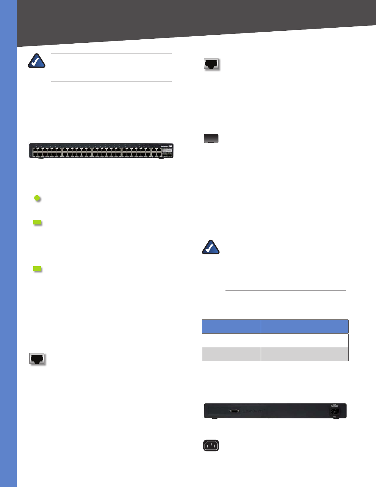
SRW248G4
Front Panel
The Switch’s LEDs and ports are located on the front
panel.
Front Panel of the SRW248G4
LEDs
POWER (Green) Lights up green to indicate
that power is being supplied to the Switch.
LINK/ACT (1-48) (Green) Lights up green to
indicate a functional 10/100-Mbps network link
through the corresponding port (1 through 48)
with an attached device. It flashes to indicate
that the Switch is actively sending or receiving
data over that port.
LINK/ACT (G1-G4) (Green/Amber) Lights up
green to indicate a functional 10/100Mbps
network link through the corresponding port
(G1 through G4) with an attached device. It
flashes to indicate that the Switch is actively
sending or receiving data over that port.
Lights up orange to indicate a 1000-Mbps
connection on the corresponding port (G1
through G4) with an attached device. It flashes
to indicate that the Switch is actively sending or
receiving data over that port.
ETHERNET 1-48 The Switch is equipped
with 48 auto-sensing Ethernet network ports,
which use RJ-45 connectors. The Fast Ethernet
ports support network speeds of 10 Mbps
or 100 Mbps. They can operate in half and
full-duplex modes. Auto-sensing technology
enables each port to automatically detect the
speed of the device connected to it (10 Mbps
or 100 Mbps), and adjust its speed and duplex
accordingly.
ETHERNET G1-G4 The Switch is equipped with
4 auto-sensing Gigabit Ethernet network ports,
which use RJ-45 connectors. The Gigabit Ethernet
ports support network speeds of 10 Mbps,
100 Mbps, or 1000 Mbps. They can operate
in half and full-duplex modes. Auto-sensing
technology enables each port to automatically
detect the speed of the device connected to it
(10 Mbps, 100 Mbps, or 1000 Mbps), and adjust
its speed and duplex accordingly.
MiniGBIC (1-2) The miniGBIC (gigabit interface
converter) port is a connection point for a
miniGBIC expansion module, so the Switch can
be uplinked via fiber to another switch. The
MiniGBIC port provides a link to a high-speed
network segment or individual workstation at
speeds of up to 1000 Mbps.
Use the Linksys MGBT1, MGBSX1, or MGBLH1
miniGBIC modules with the Switch. The
MGBSX1 and the MGBLH1 require fiber cabling
with LC connectors, while the MGBT1 requires
a Category 5e Ethernet cable with an RJ-45
connector.
NOTE: On the SRW248G4, MiniGBIC ports
are shared with Gigabit Ethernet ports. If a
miniGBIC port is used, then the shared Gigabit
Ethernet port on the Switch cannot be used.
The following table provides port mapping
details of the SRW248G4 Switch.
SRW248G4 Shared Port Mapping
miniGBIC Port Standard Port
miniGBIC 1 Port G3
miniGBIC 2 Port G4
Back Panel
The power port is located on the back panel of the
Switch.
Back Panel of the SRW248G4
POWER The Power port is where you will
connect the AC power.
6
Product Overview
WebView Switches
Chapter 2
CONSOLE The Switch is equipped with a
serial port labeled Console (located on the
back of the switch) that allows you to connect
to a computer’s serial port (for configuration
purposes) using the provided serial cable. You
can use HyperTerminal to manage the Switch
using the console port.
Refer to Chapter 4: Configuration Using the
Console Interface for more information.
NOTE: If you need to reset the Switch, unplug
the power cord from the back of the Switch.
Wait a few seconds and then reconnect it.
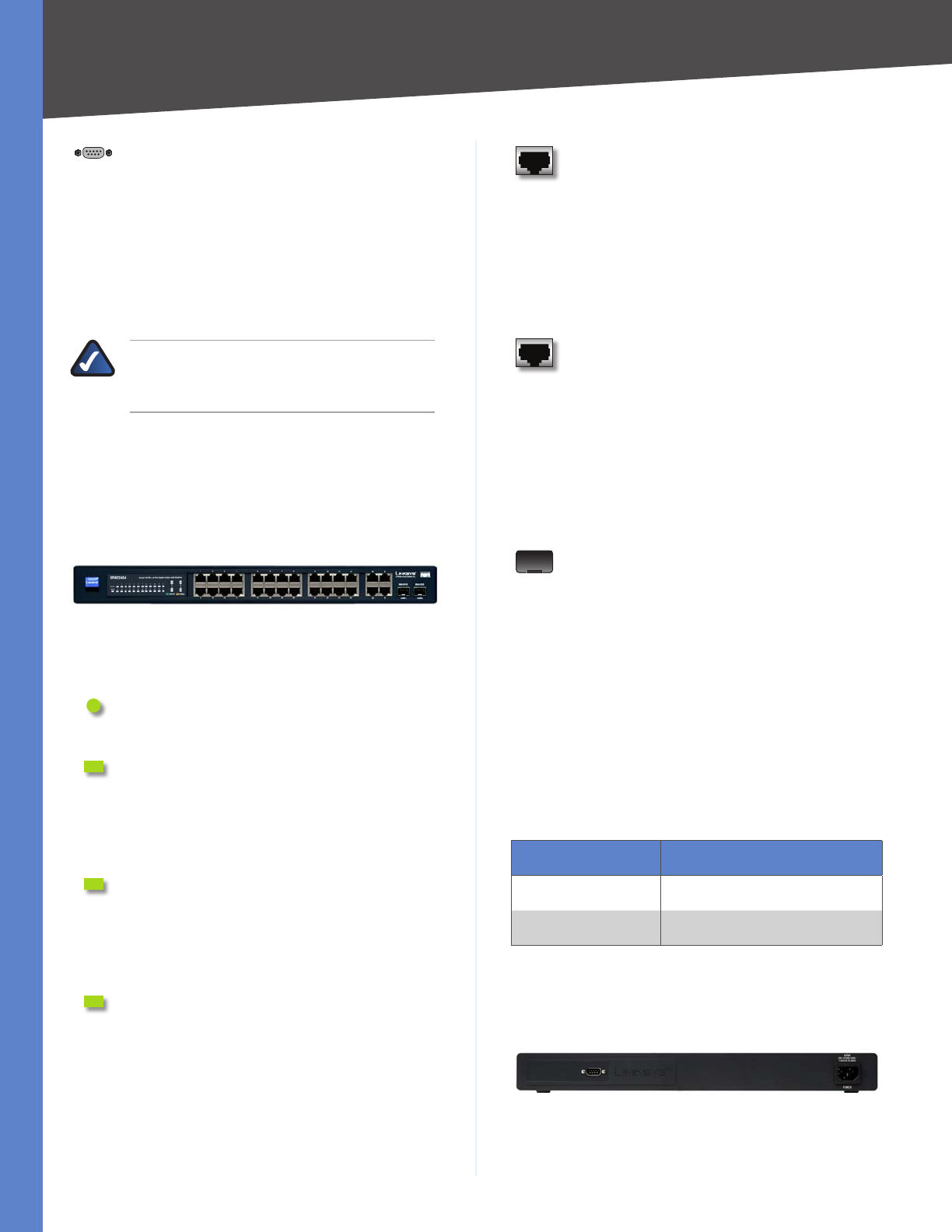
SRW224G4
Front Panel
The Switch’s LEDs and ports are located on the front
panel.
Front Panel of the SRW224G4
LEDs
POWER (Green) Lights up green to indicate
that power is being supplied to the Switch.
LINK/ACT (1-24) (Green) Lights up green to
indicate a functional 10/100-Mbps network link
through the corresponding port (1 through 24)
with an attached device. It flashes to indicate
that the Switch is actively sending or receiving
data over that port.
LINK/ACT (G1-G4) (Green) Lights up green to
indicate a functional 10/100-Mbps network link
through the corresponding port (G1 through
G4) with an attached device. It flashes to indicate
that the Switch is actively sending or receiving
data over that port..
1000Mbps (G1-G4) (Amber) Lights up amber
to indicate a 1000-Mbps connection on the
corresponding port (G1 through G4) with an
attached device.
ETHERNET 1-24 The Switch is equipped with
24 auto-sensing, Ethernet network ports, which
use RJ-45 connectors. The Fast Ethernet ports
support network speeds of 10 Mbps, 100 Mbps,
or 1000 Mbps. They can operate in half and
full-duplex modes. Auto-sensing technology
enables each port to automatically detect the
speed of the device connected to it (10 Mbps,
100 Mbps, or 1000 Mbps), and adjust its speed
and duplex accordingly.
ETHERNET G1-G4 The Switch is equipped
with 4 auto-sensing Gigabit Ethernet network
ports, which use RJ-45 connectors. The Gigabit
Ethernet ports support network speeds of
10 Mbps, 100 Mbps, or 1000 Mbps. They can
operate in half and full-duplex modes. Auto-
sensing technology enables each port to
automatically detect the speed of the device
connected to it (10 Mbps, 100 Mbps, or
1000 Mbps), and adjust its speed and duplex
accordingly.
MiniGBIC (1-2) The miniGBIC (gigabit interface
converter) port is a connection point for a
miniGBIC expansion module, so the Switch can
be uplinked via fiber to another switch. The
MiniGBIC port provides a link to a high-speed
network segment or individual workstation at
speeds of up to 1000 Mbps.
Use the Linksys MGBT1, MGBSX1, or MGBLH1
miniGBIC modules with the Switch. The
MGBSX1 and the MGBLH1 require fiber cabling
with LC connectors, while the MGBT1 requires
a Category 5e Ethernet cable with an RJ-45
connector.
SRW224G4 Shared Port Mapping
miniGBIC Port Standard Port
miniGBIC 1 Port G3
miniGBIC 2 Port G4
Back Panel
The power port is located on the back panel of the
Switch.
Back Panel of the SRW224G4
7
Product Overview
WebView Switches
Chapter 2
POWER The Power port is where you will
connect the AC power.
CONSOLE The Switch is equipped with a
serial port labeled Console (located on the
back of the switch) that allows you to connect
to a computer’s serial port (for configuration
purposes) using the provided serial cable. You
can use HyperTerminal to manage the Switch
using the console port.
Refer to Chapter 4: Configuration Using the
Console Interface for more information.
NOTE: If you need to reset the Switch, unplug
the power cord from the back of the Switch.
Wait a few seconds and then reconnect it.
8
Connecting the Switch
WebView Switches
Chapter 3
Chapter 3:
Connecting the Switch
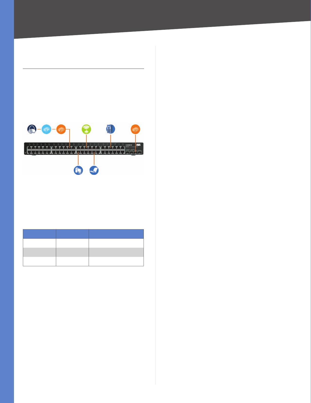
Overview
This chapter will explain how to connect network devices
to the Switch. For an example of a typical network
configuration, see the application diagram shown below.
Typical Network Configuration for the SRW2048
When you connect your network devices, make sure you
don’t exceed the maximum cabling distances, which are
listed in the following table:
Maximum Cabling Distances
From To Maximum Distance
Switch Switch or Hub 100 meters (328 feet)
Hub Hub 5 meters (16.4 feet)
Switch or Hub Computer 100 meters (328 feet)
A hub refers to any type of 100-Mbps hub, including regular hubs and †
stackable hubs. A 10-Mbps hub connected to another 10-Mbps hub
can span up to 100 meters (328 feet).
Before You Install the Switch...
When you choose a location for the Switch, observe the
following guidelines:
Make sure the Switch is accessible and that the cables •
can be easily connected.
Keep cabling away from sources of electrical noise, •
power lines, and fluorescent lighting fixtures.
Position the Switch away from water and moisture •
sources.
To ensure adequate air flow around the Switch, provide •
a minimum clearance of two inches (50 mm).
Do not stack free-standing Switches more than four •
units high.
Placement Options
There are two ways to physically install the Switch, either
set the Switch on its four rubber feet for desktop placement
or mount the switch in a standard-sized, 482.6-mm wide,
1U-high rack for rack-mount placement.
Desktop Placement
Attach the rubber feet to the recessed areas on the •
bottom of the Switch.
Place the Switch on a desktop near an AC power •
source.
Keep enough ventilation space for the switch and •
check the environmental restrictions mentioned in the
Specifications Appendix as you are placing the Switch.
Connect the Switch to network devices according to •
the Hardware Installation instructions below.
Rack-Mount Placement
When rack-mounting the Switch, please observe the
following guidelines
Elevated Operating Ambient •If installed in a closed
or multi-unit rack assembly, the operating ambient
temperature of the rack environment may be greater
than the room ambient temperature. Therefore,
consideration should be given to installing the
equipment in an environment compatible with the
maximum ambient temperature (Tma) specified by
the manufacturer.
Reduced Air Flow •Installation of the equipment
in a rack should be such that the amount of air flow
required for safe operation of the equipment is not
compromised.
Mechanical Loading •Mounting of the equipment in
the rack should be such that a hazardous condition is
not achieved due to uneven mechanical loading.
Circuit Overloading •Consideration should be given
to the connection of the equipment to the supply
circuit and the effect that overloading of the circuits
might have on overcurrent protection and supply
wiring. Appropriate consideration of equipment
nameplate ratings should be used when addressing
this concern.
Reliable Earthing •Reliable earthing of rack-mounted
equipment should be maintained. Particular attention
should be given to supply connections other than
direct connections to the branch circuit (for example,
use of power strips).
Internet
Cable/DSL
Modem Router Server
Uplink via Fiber
to Switch
Wireless Access Point
10/100/1000
Desktop
10/100
Notebook
9
Connecting the Switch
WebView Switches
Chapter 3
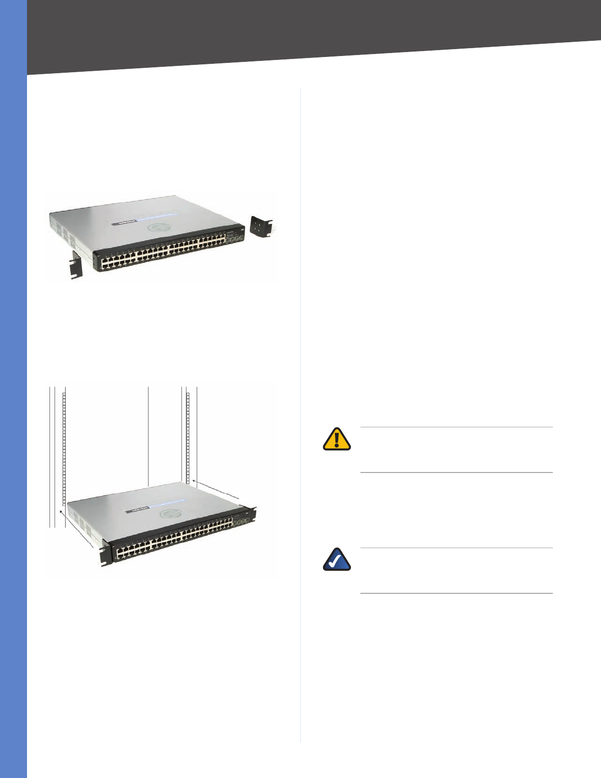
To rack-mount the Switch in any standard 482.6-mm wide,
1U high rack, follow the instructions described below.
Place the Switch on a hard flat surface with the front 1.
panel facing you.
Attach a rack–mount bracket to one side of the Switch 2.
with the supplied screws and secure the bracket
tightly.
Attach the Brackets to the Switch
Follow the same steps to attach the other bracket to 3.
the opposite side.
After the brackets are attached to the Switch, use 4.
suitable screws to securely attach the brackets to any
standard 482.6-mm rack.
Mount the Switch in the Rack
Connect the Switch to network devices according to 5.
the Hardware Installation instructions below.
Hardware Installation
To connect network devices to the Switch, follow these
instructions:
Make sure all the devices you will connect to the Switch 1.
are powered off.
For 10/100-Mbps devices, connect a Category 5 2.
Ethernet network cable to one of the numbered ports
on the Switch. For a 1000-Mbps device, connect a
Category 5e Ethernet network cable to one of the
numbered ports on the Switch.
Connect the other end to a PC or other network 3.
device.
Repeat steps 2 and 3 to connect additional devices.4.
If you are using the miniGBIC port, then connect the 5.
miniGBIC module to the miniGBIC port. For detailed
instructions, refer to the module’s documentation.
If you will use the Switch’s console interface to 6.
configure the Switch, then connect the supplied serial
cable to the Switch’s Console port, and tighten the
captive retaining screws. Connect the other end to your
PC’s serial port. (This PC must be running the VT100
terminal emulation software, such as HyperTerminal.)
Connect the supplied power cord to the Switch’s power 7.
port, and plug the other end into an electrical outlet.
WARNING: Make sure you use the power
cord that is supplied with the Switch. Use of a
different power cord could damage the Switch.
Power on the network devices connected to the 8.
Switch. Each active port’s corresponding Link/Act
LED will light up on the Switch. If a port has an active
Gigabit connection, then its corresponding Gigabit
LED will also light up.
NOTE: If you need to reset the Switch, unplug
the power cord from the back of the Switch.
Wait a few seconds and then reconnect it.
Configuring the Switch
To use the Switch’s console interface to configure the
Switch, proceed to Chapter 4: Configuration Using the
Console Interface for directions.
To use the Switch’s Web-based Utility to configure the
Switch, proceed to Chapter 5: Advanced Configuration.
10
Configuration Using the Console Interface
WebView Switches
Chapter 4
Chapter 4:
Configuration Using the
Console Interface
Overview
The Switch features a menu-driven console interface for
basic configuration of the Switch and management of your
network. The Switch can be configured using CLI through
the console interface or through a Telnet connection.
This chapter describes console interface configuration.
Configuration can also be performed through the web
utility, which is covered in the next chapter.
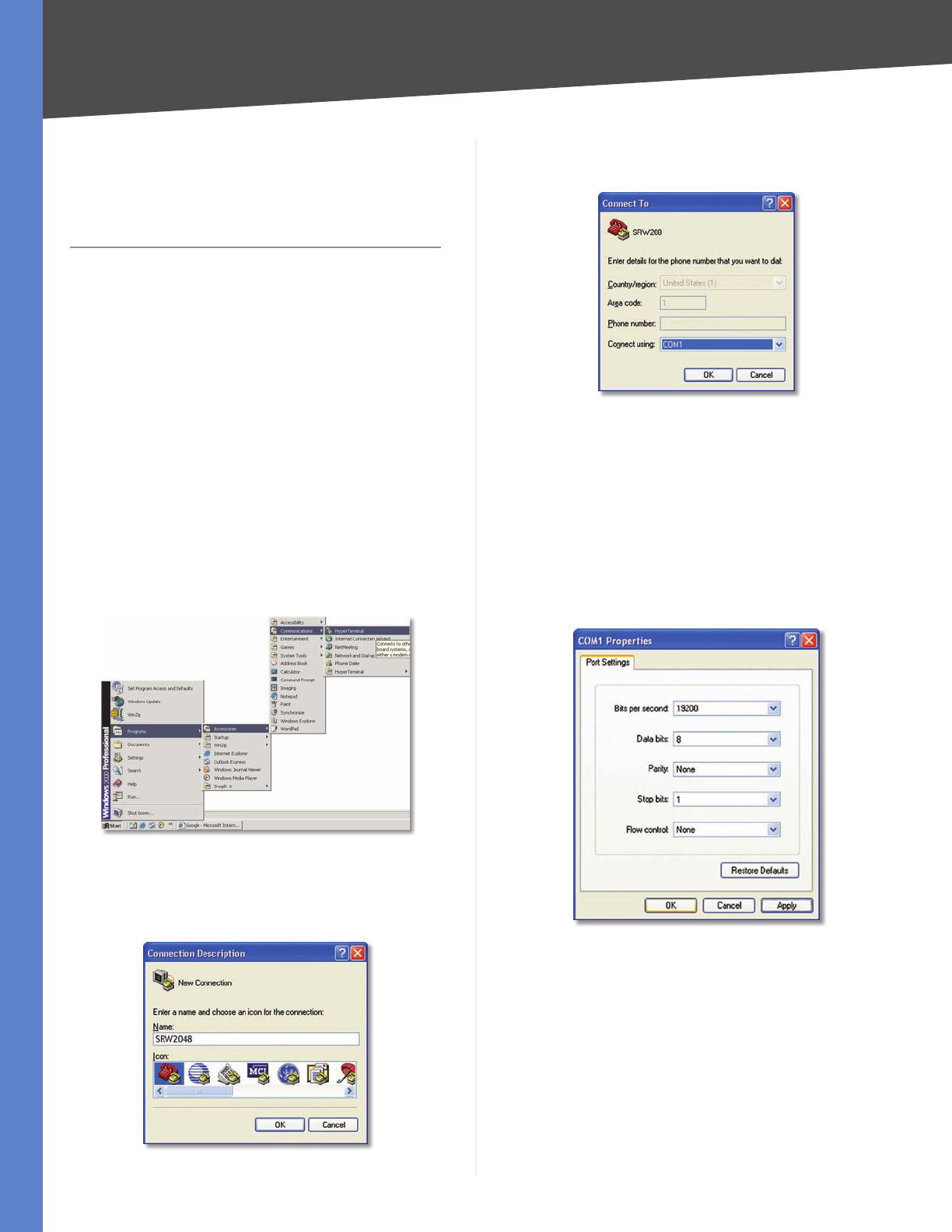
Configuring the HyperTerminal Application
Before using the console interface, configure the
HyperTerminal application on your PC as follows:
Click the 1. Start button.
Select 2. Programs > Accessories > Communications >
HyperTerminal.
Start > Programs > Accessories > Communications > HyperTerminal
Enter a name for this connection. In this example, the 3.
name of connection is SRW2048. Select an icon for the
application, then click OK.
HyperTerminal Connection Description Screen
Select a port to communicate with the Switch: 4. COM1,
COM2, or TCP/IP.
HyperTerminal Connect To Screen
Set the serial port settings as follows:5.
Bits per second: 38,400
Data bits: 8
Parity: None
Stop bits: 1
Flow control: None
Click 6. OK.
HyperTerminal Properties Screen
Connecting to the Switch through a Telnet
Session
Open a command-line editor and enter telnet
192.168.1.254. Then, press the Enter key.
The Login screen appears. The first time you open the
command-line interface (CLI), select Edit and press Enter.
Enter admin in the User Name field. Leave the Password
field blank.
11
Configuration Using the Console Interface
WebView Switches
Chapter 4
Telnet Login Screen
Press the Esc button to return to the login screen. Use the
right arrow button to navigate to the Execute option and
press the Enter button to open CLI interface.
Configuring the Switch through the
Console Interface
The console screens consist of a series of menus. Each
menu has several options, which are listed vertically. You
select a menu option when you highlight it; pressing the
Enter key activates the highlighted option.
To navigate through the menus and actions of the console
interface, use the up or down arrow keys to move up
or down, and use the left or right arrow keys to move
left or right. Use the Enter key to select a menu option,
and use the Esc key to return to the previous selection.
Menu options and any values entered or present will be
highlighted. The bottom of the screen lists the actions
available.
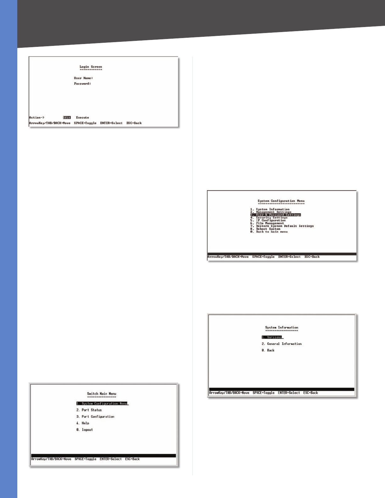
Switch Main Menu
The System Main Menu screen displays these choices:
System Configuration Information Menu1.
Port Status2.
Port Configuration3.
Help4.
Logout5.
Switch Main Menu
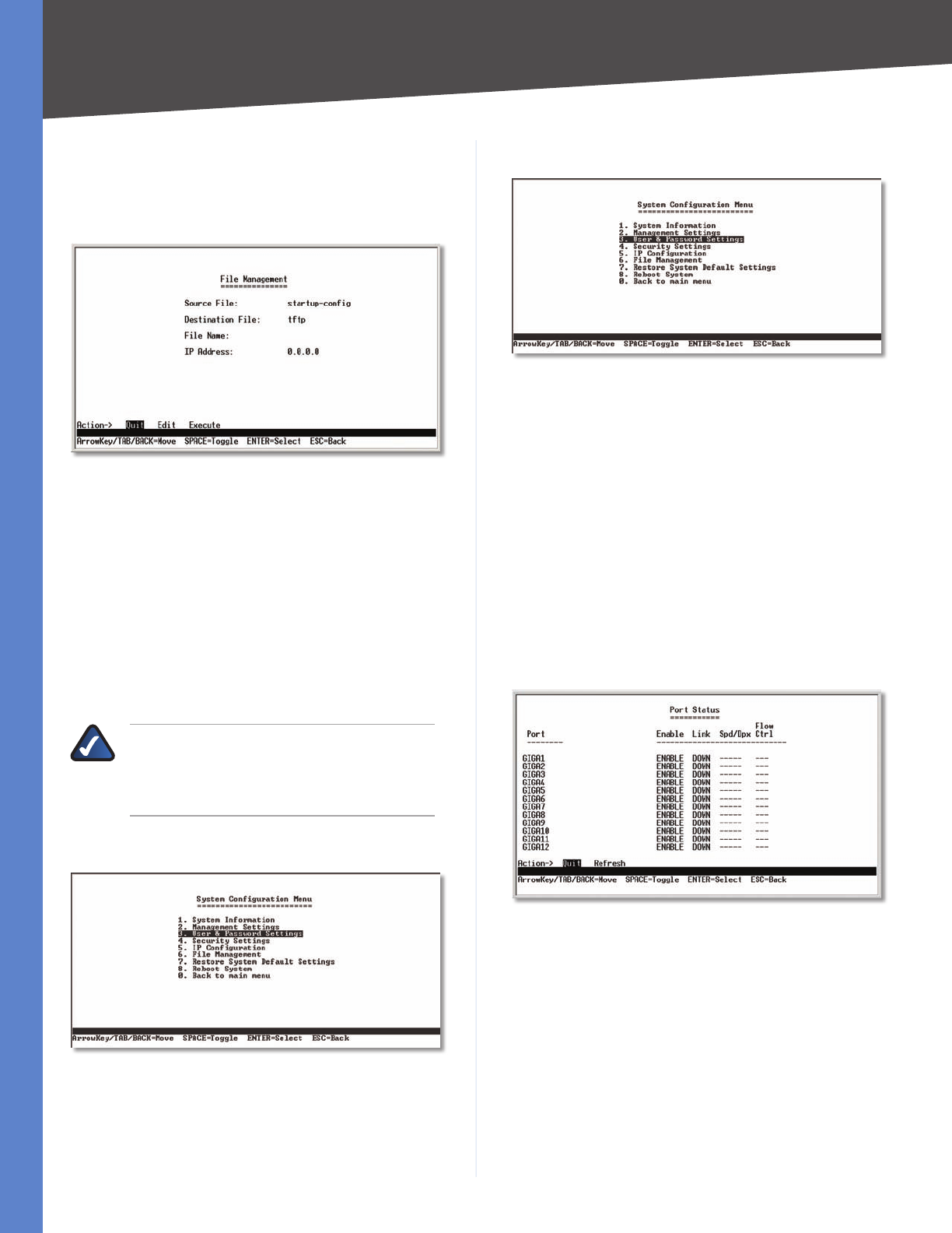
System Configuration Menu
On the System Configuration Menu screen, you can choose
from the following:
System Information1.
Management Settings2.
User & Password Settings3.
Security Settings4.
IP Configuration5.
File Management6.
Restore System Default Settings7.
Reboot System8.
Back to main menu9.
System Configuration Menu
System Information
Using System Information screen, you can check the Switch’s
firmware versions and general system information.
System Configuration Menu
12
Configuration Using the Console Interface
WebView Switches
Chapter 4
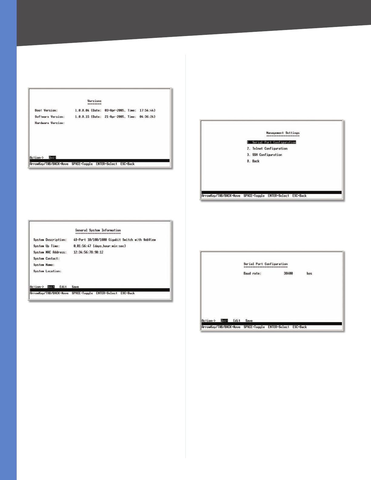
Versions
The Versions screen displays the Switch’s boot, software,
and hardware firmware versions.
Versions
General System Information
The General System Information screen displays general
information about the Switch.
General System Information
Select Edit and press the Enter key to make changes.
When your changes are complete, press the Esc key to
return to the Action menu. Select Save and press the
Enter key to save your changes. To exit, select Quit and
press the Enter key.
Management Settings
From the Management Settings screen, you can set the
following options:
Serial Port Session Configuration •
Telnet Session Configuration •
Secure Telnet (SSH) Configuration. •
Management Settings Menu
Serial Port Configuration
The Serial Port Configuration screen displays the Switch’s
baud rate.
Serial Port Configuration
Select Edit and press the Enter key to make changes.
Toggle to the desired speed and when your changes are
complete, press the Esc key to return to the Action menu.
Select Save and press the Enter key to save your changes.
To exit, select Quit and press the Enter key.

13
Configuration Using the Console Interface
WebView Switches
Chapter 4
Telnet Configuration
The Telnet Configuration screen displays the timeout value.
The value is entered in seconds. If you do not want the
Telnet session to timeout, you may enter a value of 0 sec.
Telnet Configuration
Select Edit and press the Enter key to make changes.
When your changes are complete, press the Esc key to
return to the Action menu. Select Save and press the
Enter key to save your changes. To exit, select Quit and
press the Enter key.
SSH Configuration
The SSH Configuration screen displays the following
options:
SSH Server Configuration •
SSH Server Status •
SSH Crypto Key Generation •
SSH Keys Fingerprints •
SSH Configuration
SSH Server Configuration
On the SSH Server Configuration screen, you can enable
or disable the SSH Server by navigating to the SSH Server
option and using the SPACE bar to toggle the option. The
SSH Server Port can be modified by entering in the value.
SSH Server Configuration
Select Edit and press the Enter key to make changes.
When your changes are complete, press the Esc key to
return to the Action menu. Select Save and press the
Enter key to save your changes. To exit, select Quit and
press the Enter key.
SSH Status
The SSH Status screen displays whether the SSH Server is
enabled, the RSA and DSA key status, and any open SSH
sessions.
SSH Status
Select Refresh to update the screen if necessary. To exit,
select Quit and press the Enter key.
14
Configuration Using the Console Interface
WebView Switches
Chapter 4
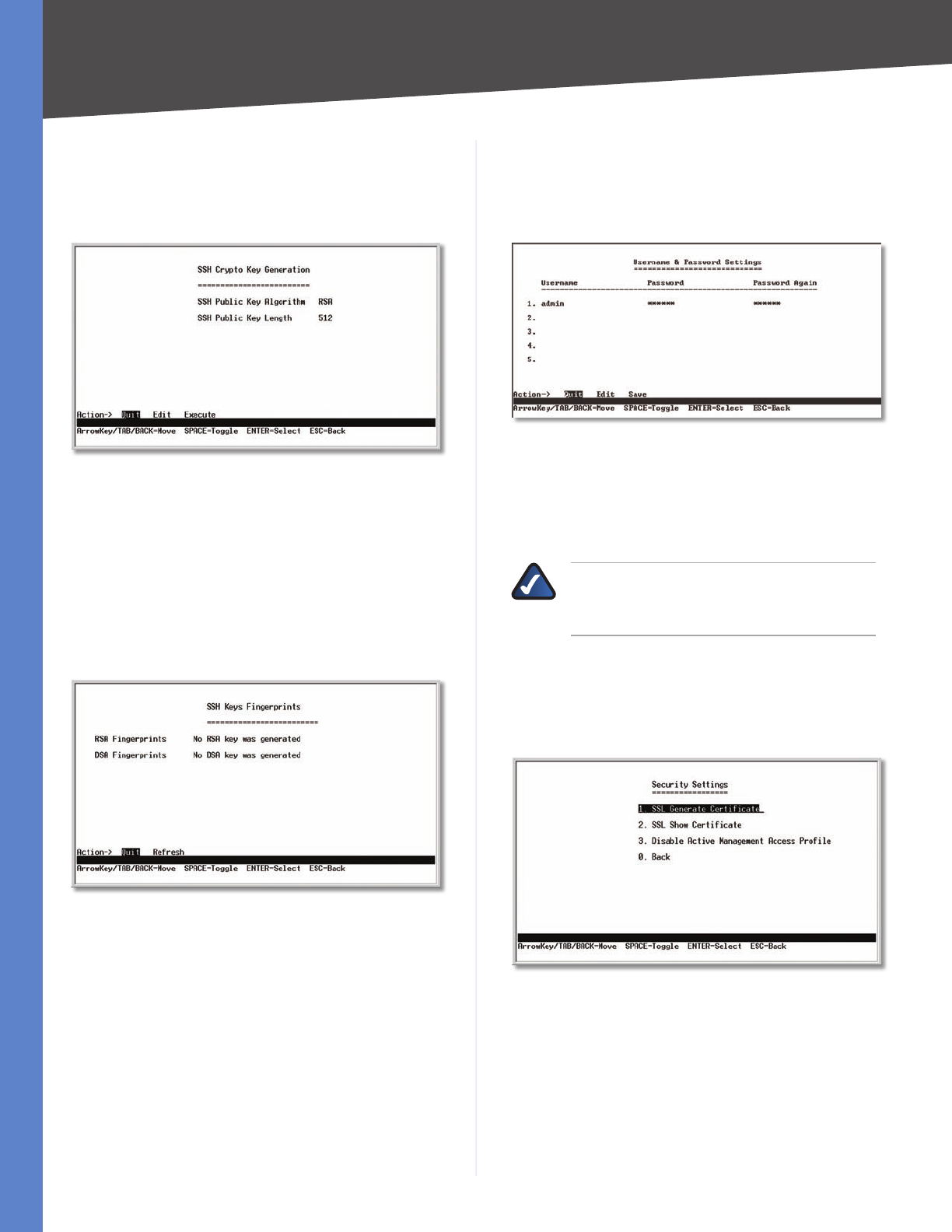
SSH Crypto Key Generation
On the SSH Crypto Key Generation screen, you can toggle
between RSA and DSA using the SPACE bar. The SSH
Public Key Length cannot be modified.
SSH Crypto Key Generation
Select Edit and press the Enter key to make changes.
When your changes are complete, press the Esc key to
return to the Action menu. Select Save and press the
Enter key to save your changes. To exit, select Quit and
press the Enter key.
SSH Keys Fingerprints
On the SSH Keys Fingerprints screen, the RSA and DSA keys
are displayed if they have been generated.
Keys Fingerprints
Select Refresh to update the screen if necessary. To exit,
select Quit and press the Enter key.
Username & Password Settings
From the Username & Password Settings screen, you
can administer the user names and passwords of those
accessing the Switch.
Username & Password Settings
Select Edit and press the Enter key to make changes.
When your changes are complete, press the Esc key to
return to the Action menu. Select Save and press the
Enter key to save your changes. To exit, select Quit and
press the Enter key.
NOTE: The Username & Password Settings
screen can also be used to set passwords for
other users.
Security Settings
The Security Settings screen enables you to configure
security settings on the Switch, as well as generate and
display the certificate.
Security Settings
15
Configuration Using the Console Interface
WebView Switches
Chapter 4
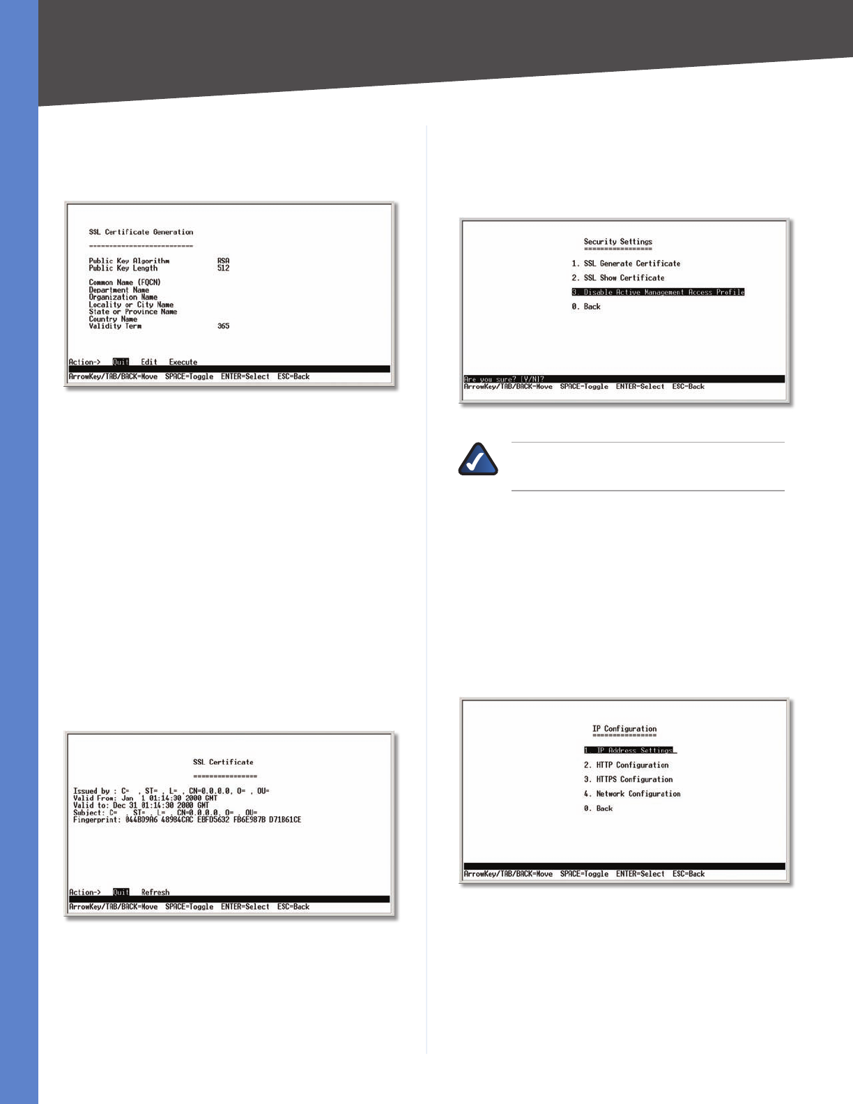
SSL Certificate Generation
Use the Certificate Generation screen to specify a device-
generated certificate.
SSL Certificate Generation
Public Key Length Specifies the SSL RSA key length.
(Range: 512–2048)
Organization Name Specifies the organization name.
(Range: 1–64)
Locality or City Name Specifies the location or city name.
(Range: 1–64)
State or Province Name Specifies the state or province
name. (Range: 1–64)
Country Name Specifies the country name. (Range: 2–2)
Validity Term Specifies number of days certification is
valid. (Range: 30–3650)
Show Certificate
Use the Show Certificate screen to display the internal
certificate.
SSL Certificate
Disable Active Management Profile
To disable the active management profile, selecting
Disable Active Management Profile from the Security
Settings screen. You are prompted for confirmation.
Security Settings
NOTE: This setting has no effect when
Management Access Rules are not defined.
IP Configuration
The IP Configuration screen lets you configure the following
options:
IP Address Settings •
HTTP Configuration •
HTTPS Configuration •
Network Configuration. •
IP Configuration
16
Configuration Using the Console Interface
WebView Switches
Chapter 4
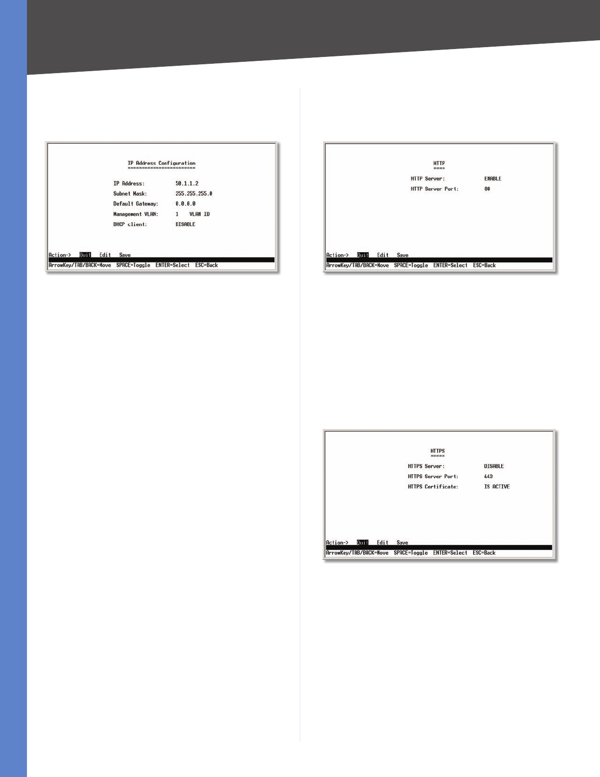
IP Address Configuration
The IP Address Configuration screen lets you configure
the Switch’s IP address information.
IP Address Configuration
IP Address The IP Address of the Switch is displayed.
(The default IP address is 192.168.1.254.) Verify that the
address you enter is correct and does not conflict with
another device on the network.
Subnet Mask The subnet mask of the Switch is
displayed.
Default Gateway The IP address of your network’s
default gateway is displayed.
Management VLAN The VLAN ID number is displayed.
DHCP client The status of the DHCP client is displayed.
If you want the Switch to be a DHCP client, then select
ENABLE. If you want to assign an static IP address to the
Switch, then enter the IP settings and select DISABLE.
Select Edit to make changes. When your changes are
complete, press the Esc key to return to the Action menu,
and select Save to save your changes.
HTTP
The HTTP screen lets you configure the status and port
number of the HTTP Server.
HTTP
Select Edit and press the Enter key to make changes.
When your changes are complete, press the Esc key to
return to the Action menu. Select Save and press the
Enter key to save your changes. To exit, select Quit and
press the Enter key.
HTTPS Configuration
The HTTPS Configuration screen lets you configure the
HTTPS settings. You can enable or disable the HTTPS server
and configure the port on which the session is enabled.
HTTPS Configuration
Select Edit and press the Enter key to make changes.
When your changes are complete, press the Esc key to
return to the Action menu. Select Save and press the
Enter key to save your changes. To exit, select Quit and
press the Enter key.
17
Configuration Using the Console Interface
WebView Switches
Chapter 4
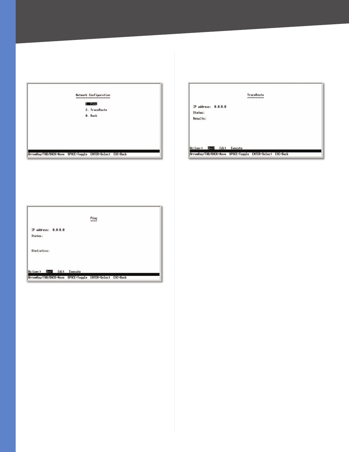
Network Configuration
The Network Configuration screen offers a choice of two
tests: Ping and TraceRoute.
Network Configuration
Ping
The Ping screen displays the IP address of the location you
want to contact.
Ping Test
Select Edit to change the IP address, and select Execute
to begin the ping test.
After the ping test is complete, the Ping screen displays
the IP address, status, and statistics of the ping test.
Select Edit and press the Enter key to make changes.
When your changes are complete, press the Esc key to
return to the Action menu. Select Save and press the
Enter key to save your changes. To exit, select Quit and
press the Enter key.
TraceRoute
The TraceRoute screen displays the IP address of the
address whose route you want to trace.
TraceRoute Test
Select Edit to change the IP address, and select Execute
to begin the traceroute test.
After the traceroute test is complete, the TraceRoute
screen displays the IP address, status, and statistics of the
traceroute test.
Select Edit and press the Enter key to make changes.
When your changes are complete, press the Esc key to
return to the Action menu. Select Save and press the
Enter key to save your changes. To exit, select Quit and
press the Enter key.
18
Configuration Using the Console Interface
WebView Switches
Chapter 4
File Management
The File Management screen allows you to upload or
download files, such as the startup configuration, boot, or
image file, using a TFTP server.
File Management
Select Edit to change the settings. When your changes are
complete, press the Esc key to return to the Action menu,
and select Execute to upload or download the designated
file.
If you are downloading a new boot & image, please follow
these steps:
Download the new boot code. DO NOT RESET THE
1.
DEVICE!
Download the new software image.
2.
Reset the device now.3.
NOTE: When downloading a configuration file,
be sure that it is a valid configuration file. If
you have edited the file, ensure that only valid
entries have been configured.
Restore System Default Settings
Restore System Default Settings
To restore the Switch back to the factory default settings,
select Restore System Default Settings and press the
Enter key. You will be asked if you want to continue. Press
the y key to restore the Switch’s default settings, or press
the n key to cancel.
Reboot System
Reboot System
Select Reboot System and press the Enter key if you
want to restart the Switch. You will be asked if you want to
continue. Press the y key to reboot the Switch, or press the
n key to cancel. After the Switch has rebooted, the Switch
Main Menu screen will appear.
Back to main menu
Select Back to main menu and press the Enter key if you
want to return to the Switch Main Menu screen.
Port Status
On the Switch Main Menu screen, select Port Status
and press the Enter key if you want to view the status
information for the Switch’s ports.
Port Status
The Port Status screen displays the port numbers, their
status, Link status, speed and duplex mode, and status of
flow control, which is the flow of packet transmissions.
If you want to change any settings for a port, you must use
the Port Configuration screen.
19
Configuration Using the Console Interface
WebView Switches
Chapter 4
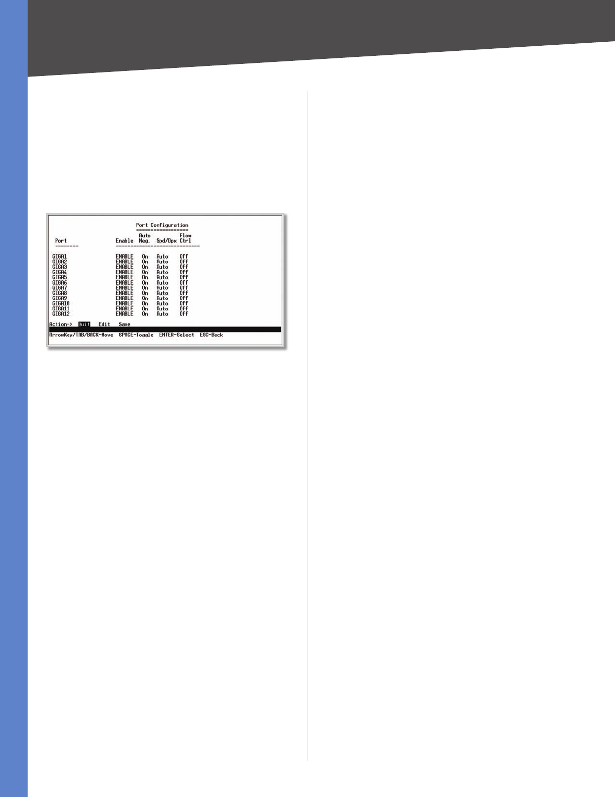
Port Configuration
On the Switch Main Menu screen, select Port Configuration
and press the Enter key if you want to configure the
Switch’s ports.
The Port Configuration screen displays the port numbers,
their status, auto-negotiation status, speed and duplex
mode, and status of flow control, which is the flow of
packet transmissions.
Port Configuration
Select Edit and press the Enter key to make changes.
When your changes are complete, press the Esc key to
return to the Action menu. Select Save and press the
Enter key to save your changes. To exit, select Quit and
press the Enter key.
Help
Select Help and press the Enter key if you want to view
the help information. This screen explains how to navigate
the various screens of the console interface.
Chapter 5 Advanced Configuration
20
WebView Switches
Chapter 5:
Advanced Configuration
Overview
This chapter describes the features included in the Web-
based Utility. All of the features shown in this chapter,
unless specifically identified, are included in all of the
WebView Switches. The screen images were taken from
the SRW2048 Switch. Additional features for specific
Switches are noted. The SRW224G4, SRW248G4, SRW2016,
and SRW2024 Switches may not support all functions.
Accessing the Web-based Utility
NOTE: The Web-based Utility is optimized
for viewing with a screen resolution of 1024 x
768. Internet Explorer version 5.5 or above is
recommended.
Open your web browser and enter 192.168.1.254 into
the Address field. Press the Enter key and the login screen
appears.
Login Screen
NOTE: The default IP address of the device
is 192.168.1.254. If you have modified this
address, enter the correct IP address. The
device should be on the same subnet as the
management station used to configure the
device.
The first time you open the Web-based Utility, enter
admin in the User Name field, and leave the Password
field blank. Click the OK button. For security purposes,
it is recommended that you set a new password on the
System Password screen. the System Password screen.
NOTE: After configuring values using the Web-
based Utility, you may be required to refresh
the page to see the updated configuration.
The first screen that appears is the Setup Summary screen.
Twelve main tabs are accessible from the Web-based
Utility: Setup, Port Management, VLAN Management,
Statistics, ACL, Security, QoS (Quality of Service),
Spanning Tree, Multicast, SNMP, Admin, and Logout.
Click one of the main tabs to view additional tabs.
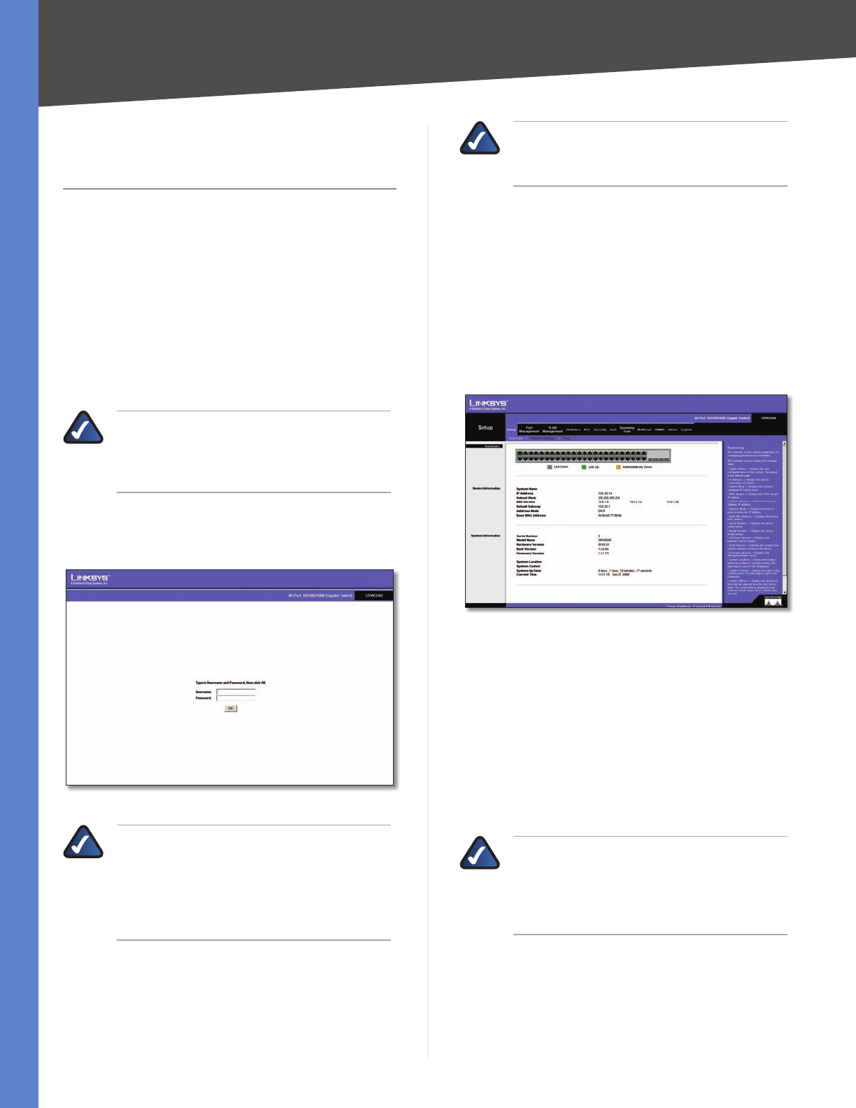
Setup > Summary
The Summary screen provides device and system
information about the Switch.
Setup > Summary
At the top of the Summary screen, an image of the Switch‘s
front panel provides the following color-coded status
information for the Switch’s Ethernet ports:
Green Indicates a connection.
Grey Indicates no connection.
Orange Indicates the port has been closed down by the
administrator.
When you click a port’s LED, the statistics for that port are
displayed.
NOTE: The port colors in the Summary screen
are not related to the colors of the LEDs on the
Switch’s ports. The port LEDs display different
status information, as described in Chapter
2: Product Overview.
Device Information
System Name Displays the name for the Switch, if one
has been entered on the Setup tab’s Network Settings
screen.

Chapter 5 Advanced Configuration
21
WebView Switches
IP Address The IP address assigned to the Switch. This
setting can be configured from the Setup tab’s Network
Settings screen.
Subnet Mask The Subnet Mask assigned to the Switch.
This setting can be configured from the Setup tab’s
Network Settings screen.
DNS Servers The IP address of your ISP’s server that
translates the names of websites into IP addresses. This
setting can be configured from the Setup tab’s Network
Settings screen.
Default Gateway The IP address of the gateway router
between the Switch and management stations on other
network segments. This setting can be configured from
the Setup tab’s Network Settings screen.
Address Mode Specifies whether IP functionality is
enabled via manual configuration (Static) or Dynamic
Host Configuration Protocol (DHCP). This setting can be
configured from the Setup tab’s Network Settings screen.
Base MAC Address Displays the MAC address of the
Switch.
System Information
Serial Number Displays the Switch’s Serial Number.
Model Name Displays the model name of the Switch.
Hardware Version Displays the Switch’s current hardware
version.
Boot Version Displays the current boot version of the
Switch.
Firmware Version Displays the Switch’s software
version.
System Location Displays the location of the system if it
has been defined. This setting can be configured from the
Setup tab’s Network Settings screen.
System Contact The name of the administrator appears
here, if one has been defined. This setting can be configured
from the Setup tab’s Network Settings screen.
System Up Time Displays the length of time that has
elapsed since the Switch was last reset.
Current Time Displays the current time. This setting can
be configured from the Setup tab’s Time screen.
Setup > Network Settings
The Network Settings screen allows you to assign DHCP
or static IP settings to interfaces and assign default
gateways.
Setup > Network Settings
Identification
System Name Specifies the name of the Switch. Enter
the name into the text field provided. By default, a system
name is not defined.
System Location This field is used to enter a description
of where the Switch is physically located, such as 3rd
Floor.
System Contact Enter the name of the administrator
responsible for the system.
System Object ID
Displays t
he system object identifier.
Base MAC Address
Displays the physical address of the
Switch
.
IP Configuration
Management VLAN This drop-down menu allows you to
select the Management VLAN.
IP Address Mode Specifies whether IP functionality is
enabled via manual configuration (Static) or Dynamic
Host Configuration Protocol (DHCP). Select Static or
DHCP from the drop-down menu. Selecting Static will
allow you to enter a static IP address, subnet mask and
default gateway using the text field provided. The default
setting is DHCP.
Host Name Enter the DHCP Host Name here.
IP Address If you are using a static IP address, enter the
IP address here.
Subnet Mask If you are using a static IP address, enter
the subnet mask for the currently configured IP address.
Default Gateway If you are using a static IP address,
enter the IP address of the default gateway.
DNS Server If you are using a static IP address, enter the
IP address of the DNS server. A second DNS address can be
specified in the additional text field provided.
Chapter 5 Advanced Configuration
22
WebView Switches
Click Save Settings to save your changes. Click Cancel
Changes to cancel your changes.
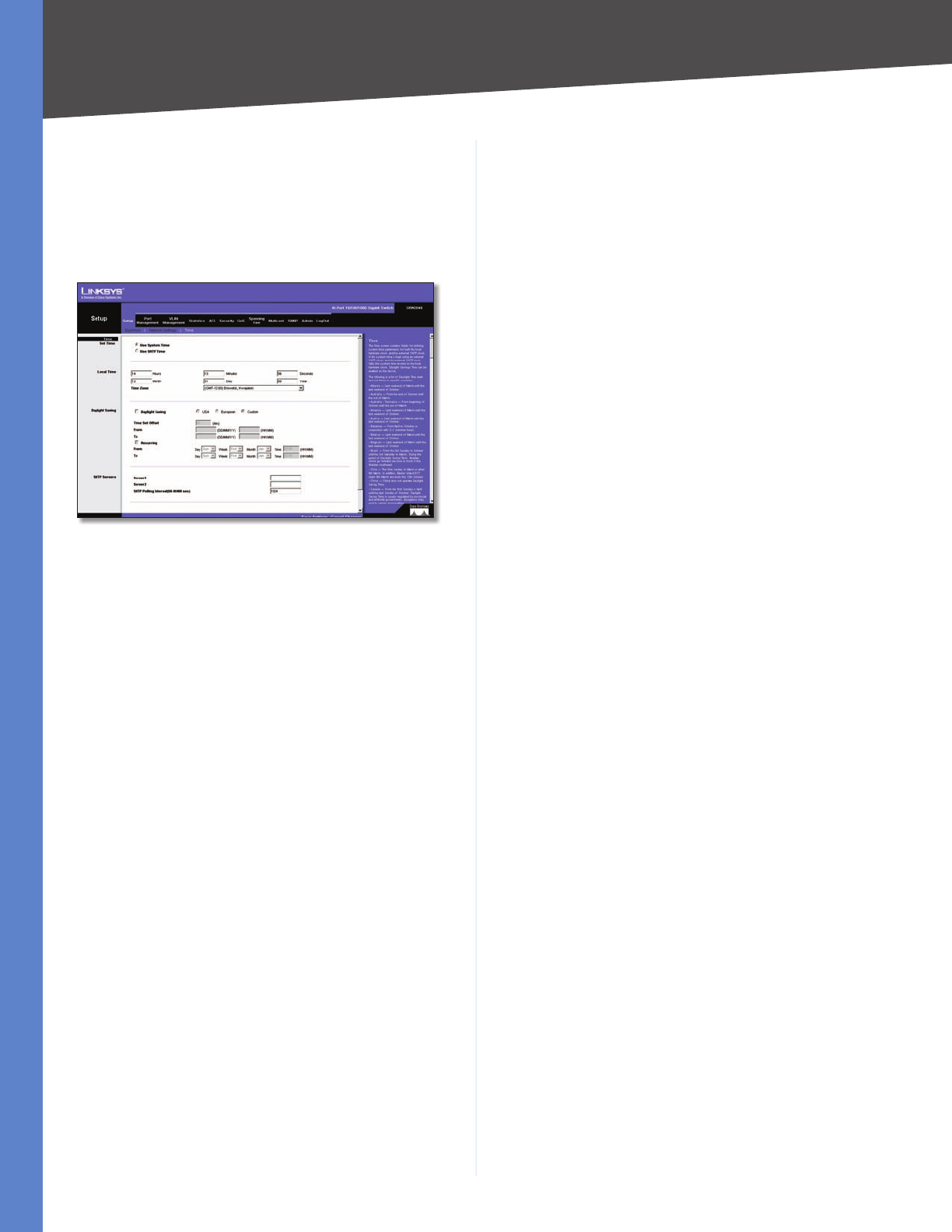
Setup > Time
The Time screen allows you to configure the time settings
for the Switch.
Setup > Time
Set Time
Use System Time Select this option to use the local
hardware clock.
Use SNTP Time Select this option to synchronize the
time to an SNTP (Simple Network Time Protocol) server.
Local Time
Hours Enter the two-digit hour here.
Minutes Enter the two-digit minutes here.
Seconds Enter the two-digit seconds here.
Month Enter the two-digit month here.
Day Enter the two-digit day here.
Year Enter the last two digits of the year here (for example,
08 instead of 2008).
Time Zone Select your time zone from the drop-down
menu. Time zones are identified by the difference between
Greenwich Mean Time (GMT) and local time.
Daylight Saving
Daylight Saving Select Daylight Saving to enable it on
the Switch. If the Switch should use US daylight savings,
then select USA. If the Switch should use EU daylight
savings, then select European. If it should use another
kind of daylight savings, then select Custom and complete
the From and To fields.
Time Set Offset For non-US and European countries,
specify the amount of time for daylight savings. The
default is 60 minutes. The range is (1–1440).
From If you selected Other for the Daylight Saving setting,
enter the date and time when daylight savings begins.
To If you selected Other for the Daylight Saving setting,
enter the date and time when daylight savings ends.
Recurring If you selected Other for the Daylight Saving
setting and daylight savings has the same start and end
dates and times every year, select Recurring.
From If you selected Recurring, enter the date and time
when daylight savings begins.
To If you selected Recurring, enter the date and time
when daylight savings ends.
SNTP Servers
Server1 Enter the primary SNTP server here.
Server2 Enter a secondary SNTP server here.
SNTP Polling Interval (60–86400 sec) Specify the
amount of time (in seconds) before the Switch polls the
SNTP server. The default value is every 1024 seconds
(approx. 17 minutes).
Click the Save Settings button to save your changes or
click Cancel Changes to discard the information.
Chapter 5 Advanced Configuration
23
WebView Switches
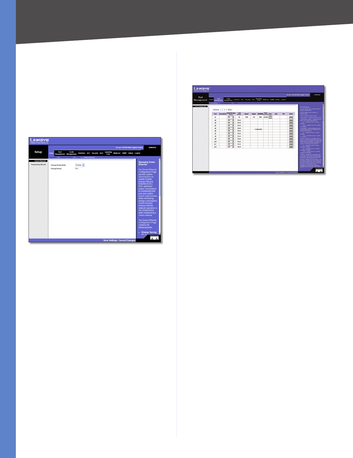
Setup > Green Ethernet
The Green Ethernet Configuration screen allows you to
enable energy-efficient Ethernet (EEE). EEE optimizes
power consumption by monitoring both port and
system power requirements, while minimizing energy
consumption. Green Ethernet ensures that the network
operation is not comprimised, while at the same time
maintaining a Green network.
This feature has been added to version 1.1 of SRW2048
and to version 1.3 of SRW2024 and SRW2016.
Setup > Green Ethernet
Energy Saving Mode Indicates if Green Ethernet is
enabled on the device. The possible field values are:
Enable •Enables Green Ethernet on the device. This is
the default value.
Disable •Disables Green Ethernet on the device.
Energy Saving Indicates the amount of energy conserved
by enabling Green Ethernet.
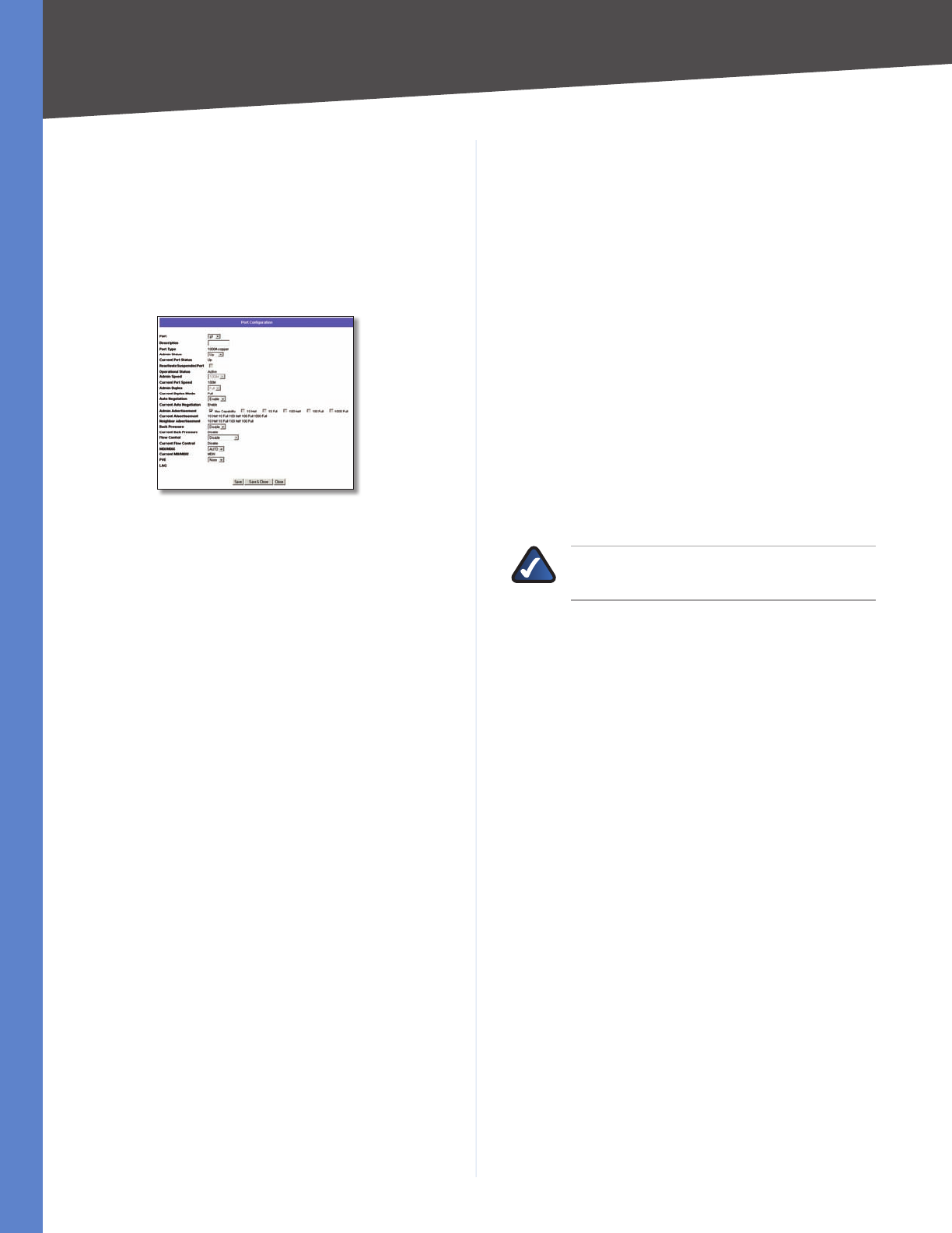
Port Management > Port Settings
The Port Settings screen shows you the settings for each of
the Switch’s ports.
Port Management > Port Settings
Port The port number. To use an SFP module, click the
Detail button of the appropriate port (G1, G2).
Description A brief description of the port. To enter or
modify the description, click the Detail button.
Administrative Status The port’s administrative status.
To take the port offline, select the Down option. To allow
normal access to the port, select Up.
Link Status The port’s operational status. Up indicates a
port has an active connection. Down indicates there is no
active connection or the port has been taken offline by an
Administrator.
Speed The port’s configured rate in Mbps. The speed can
be configured only when auto-negotiation is disabled on
that port.
Duplex The port’s current duplex mode: Full
(transmission occurs in both directions simultaneously) or
Half (transmission occurs in only one direction at a time).
This mode can be configured only when auto-negotiation
is disabled and port speed is set to 10Mbps or 100Mbps.
It cannot be configured on Link Aggregation Groups
(LAGs).
MDI/MIDX The MDI/MDIX status of the port. The MDI
setting is used if the port is connected to an end station.
The MDIX setting is used if the port is connected to a hub
or another switch.
Flow Control The type of flow control currently in use. It
is active when the port uses the Full Duplex Mode.
Type The port type.
LAG The Link Aggregated Group (LAG) to which the port
belongs, if the port is a LAG member.
Chapter 5 Advanced Configuration
24
WebView Switches
PVE When a port is a Private VLAN Edge (PVE) port,
it bypasses the Forwarding Database and forwards all
unicast, multicast, and broadcast traffic to an uplink.
Uplinks can be ports or LAGs.
Detail The Detail button opens the Port Configuration
Detail screen.
Port Settings > Port Configuration
Port Settings > Port Configuration
Port The port number.
Description User-defined port description. To modify
the description, click Detail.
Port Type (Read-only) The port’s connection type and
speed.
Admin Status The port’s administrative status. Select
either Up or Down to enable or disable traffic forwarding
through the port.
Current Port Status (Read-only) The port’s connection
status, either Up or Down.
Reactivate Suspended Port If the port has been
suspended, select this checkbox to reactivate the port.
Operational Status (Read-only) Displays whether the
port is operational or non-operational.
Admin Speed Use this to manually set the port’s
configured transmission rate in Mbps. You can select 10M,
100M, or 1000M (Gigabit ports only). Before you change
this setting, make sure that Auto Negotiation is disabled.
Current Port Speed (Read-only) The port’s current rate
in Mbps.
Admin Duplex The port’s duplex mode (Full or Half).
Current Duplex Mode (Read-only) The port’s current
duplex mode.
Auto Negotiation Select Enable (default) or Disable
to enable or disable Auto-Negotiation on the port. Auto-
Negotiation allows a port to advertise its transmission rate,
duplex mode, and flow control settings to other ports. If
using a small-form-factor pluggable (SFP) module, select
Disable.
Current Auto Negotiation (Read-only) The port’s current
Auto-Negotiation status.
Admin Advertisement Specifies the capabilities to be
advertised by the port. Multiple options may be selected
or Max Capability can be selected to cover all of the
options. The available options are:
Max Capability •The port advertises all speeds and
duplex mode settings.
10 Half •The port advertises 10 Mbps half-duplex
operation.
10 Full •The port advertises 10 Mbps full-duplex
operation.
100 Half •The port advertises 100 Mbps half-duplex
operation.
100 Full •The port advertises 100 Mbps full-duplex
operation.
1000 Full •(Gigabit ports only) The port advertises
1000 Mbps full-duplex operation.
NOTE: The SRW248G4 and SRW224G4 offer
only the 1000 option on ports G1-G4.
Current Advertisement (Read-only) The speed
and duplex mode settings that the port is currently
advertising.
Neighbor Advertisement (Read-only) The speed and
duplex mode settings that the neighbor port (the port to
which the selected port is connected) is advertising. If the
port has no neighbor port, this field displays “Unknown.”
Back Pressure Select Enable or Disable (default) to
enable or disable Back Pressure mode on the port.
Current Back Pressure (Read-only) The current Back
Pressure mode on the port.
Flow Control Select Enable or Disable to manually
enable or disable flow control, or select Auto-Negotiation
for automatic selection of flow control on the port.
Current Flow Control (Read-only) The current flow
control setting.
MDI/MDIX Select the port’s MDI/MDIX type, either MDI,
MDIX, or Auto (automatically detect type). The MDI
setting is used if the port is connected to an end station.
The MDIX setting is used if the port is connected to a hub
or another switch.
Current MDI/MDIX (Read-only) The port’s current MDI/
MDIX type.
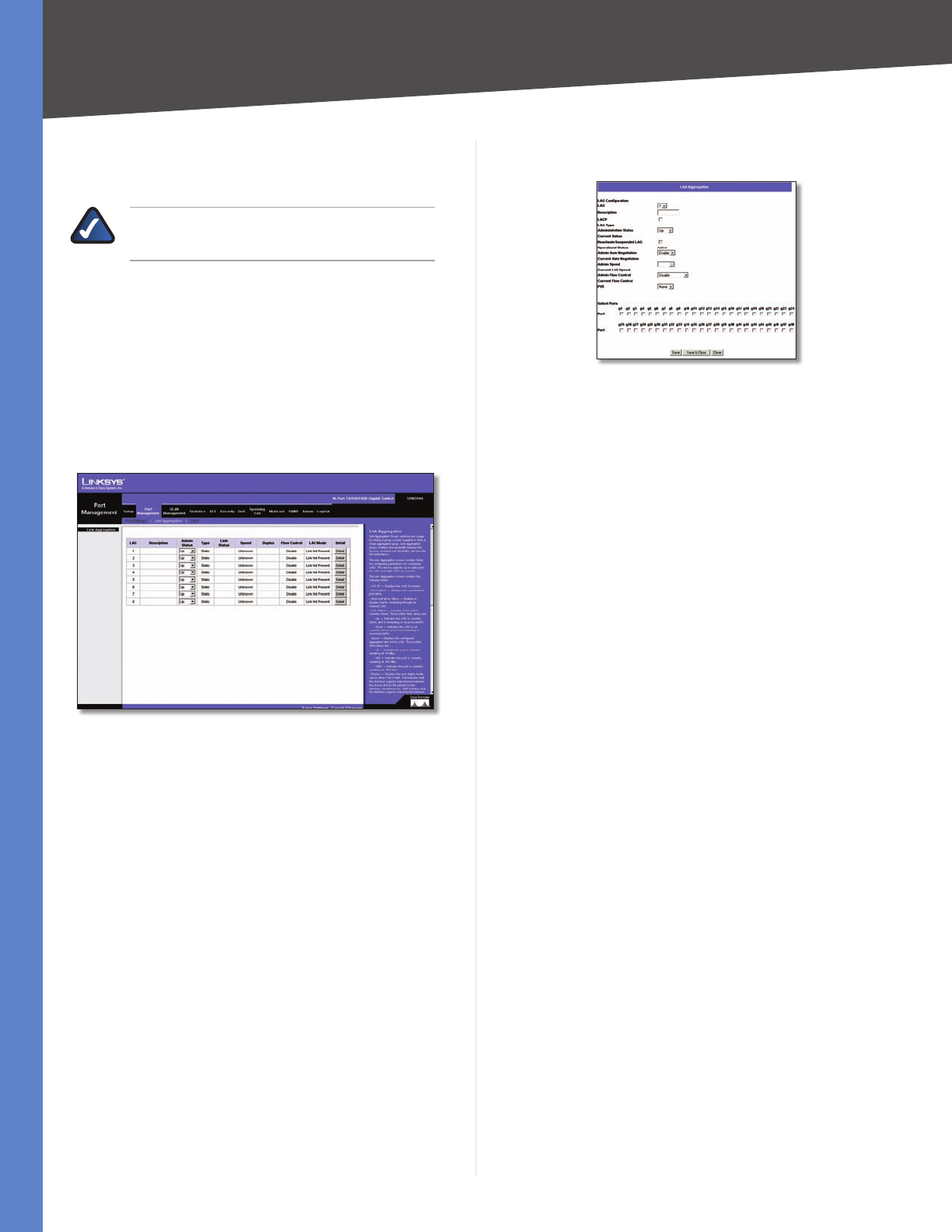
Chapter 5 Advanced Configuration
25
WebView Switches
PVE When a port is a Private VLAN Edge (PVE) port,
it bypasses the Forwarding Database and forwards all
unicast, multicast, and broadcast traffic to an uplink.
NOTE: All ports in the same PVE group should
join the same VLAN group.
LAG (Read-only) The LAG to which this port belongs, if
the port is a LAG member.
Click Save to save the settings and leave the screen open.
Click Save & Close to save the settings and close the
screen. Click Close to close the screen without saving the
settings.
Port Management > Link Aggregation
Port Management > Link Aggregation
LAG The LAG number (1-8).
Description The user-defined description for the LAG.
Admin Status The administrative status of the LAG. Up
indicates that the LAG is available. Down indicates that
administrator has taken the port offline. When modifying
the option, click Save Settings.
Type Indicates if a LAG has been manually configured
(static) or dynamically set through LACP.
Link Status Displays the status of the link.
Speed Displays the port speed.
Duplex Displays the duplex mode.
Flow Control Displays the flow control status of the LAG.
It is active when the port uses Full Duplex Mode.
LAG Mode Displays the LAG status: On, Off, or Not
Present.
Detail To create a new LAG, click Detail in the Detail
column to display the Link Aggregation detail screen.
Link Aggregation > Detail
Link Aggregation > Detail
LAG Configuration
LAG The LAG number (1-8). To display or edit another
LAG, select the number from the drop-down menu.
Description The user-defined LAG description of up to
64 characters. This field is blank by default.
LACP Select the checkbox to enable Link Aggregation
Control Protocol (LACP).
LAG Type (Read-only) The LAG type.
Administrative Status The LAG’s administrative status.
Select either Up or Down to enable or disable the LAG.
Current Status (Read-only) The LAG’s status, either Up or
Down.
Reactivate Suspended LAG If the LAG has been
suspended, select this checkbox to reactivate the LAG.
Operational Status (Read-only) Displays whether the
LAG is operational or non-operational.
Admin Auto Negotiation Enables or disables Auto
Negotiation on the LAG. Auto-negotiation is a protocol
between two link partners that enables a LAG to advertise
its transmission rate, duplex mode and flow control (the
flow control default is disabled) abilities to its partner.
Current Auto Negotiation The current Auto Negotiation
setting.
Admin Speed The configured speed at which the LAG is
operating.
Current LAG Speed (Read-only) The current speed at
which the LAG is operating.
Admin Flow Control Enables or disables flow control or
enables the auto negotiation of flow control on the LAG.
Current Flow Control (Read-only) The current flow
control setting.
PVE Displays the PVE group to which the LAG is
configured.
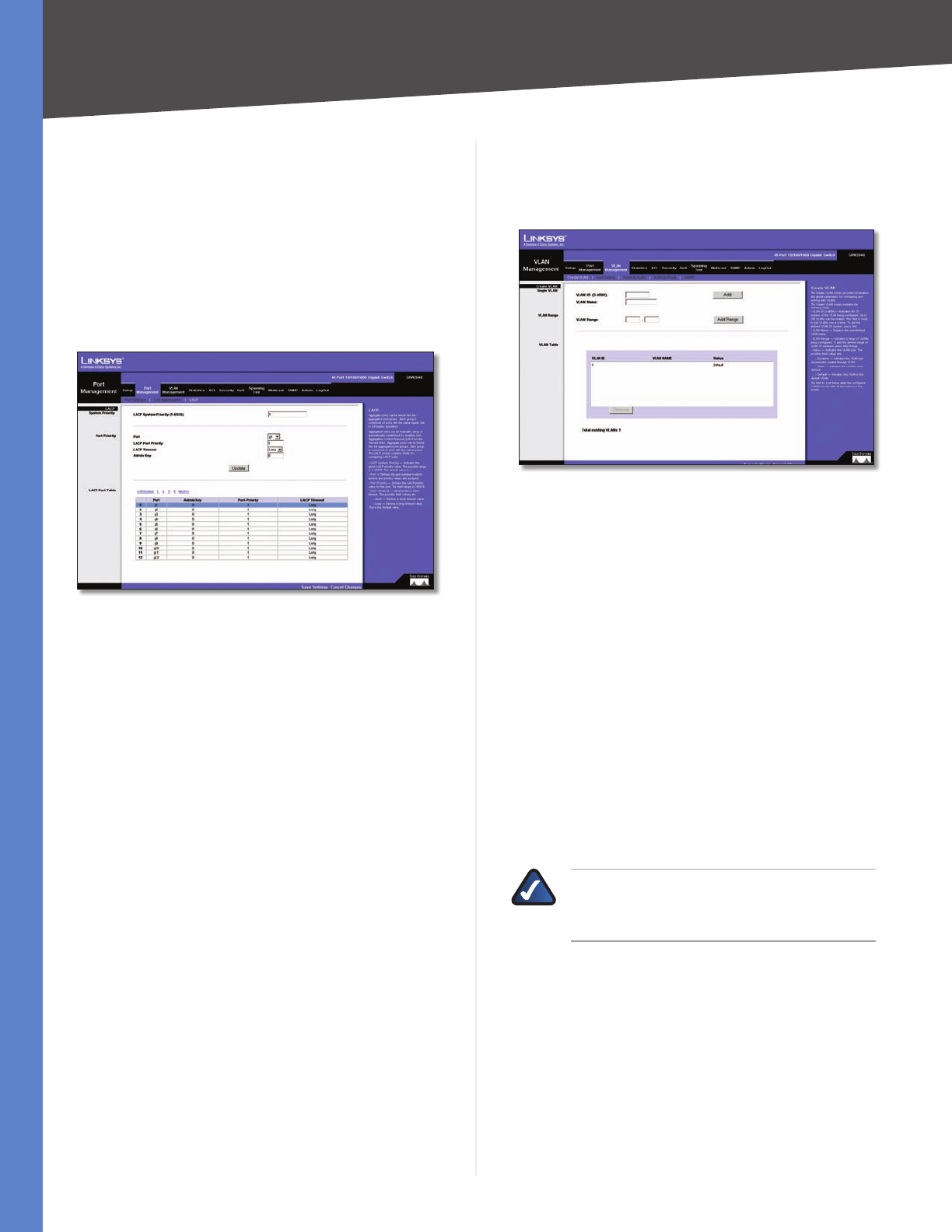
Chapter 5 Advanced Configuration
26
WebView Switches
Select Ports
Ports Displays the ports that are members of the selected
LAG.
Port Management > LACP
You can use the Link Aggregation Control Protocol (LACP)
to link aggregate ports into link aggregation port groups.
Each group is comprised of ports with the same speed, set
to full-duplex operation.
Port Management > LACP
You can manually set up aggregated links or automatically
establish them by enabling LACP on the relevant links. The
LACP screen contains fields for configuring LACP LAGs.
LACP System Priority The global LACP priority value.
The possible range is 1–65,535. The default value is 1.
Port The port number to which timeout and priority
values are assigned.
LACP Port Priority The LACP priority value for the port.
The field range is 1–65,535.
LACP Timeout Administrative LACP timeout. A short or
long timeout value can be selected. Long is the default.
Admin Key A channel will only be formed between ports
having the same admin key. This only applies to ports
located on the same switch.
VLAN Management > Create VLAN
The Create VLAN screen provides information and global
parameters for configuring and working with VLANs.
VLAN Management > Create VLAN
Single VLAN
VLAN ID (2–4094) The ID number of the VLAN being
configured. Up to 256 VLANs can be created. This field is
used to add VLANs one at a time. To add the defined VLAN
ID number, click Add.
VLAN Name The user-defined VLAN name.
VLAN Range
VLAN Range The range of VLANs being configured. To
add the defined range of VLAN ID numbers, click Add
Range.
VLAN Table
The VLAN Table displays a list of all configured VLANs. The
VLAN ID, VLAN Name, and status of the VLAN are displayed
here. To remove a VLAN, click Remove.
NOTE: VLANs that are created dynamically
using GARP VLAN Registration Protocol (GVRP)
are assigned a VLAN name “Undefined.”
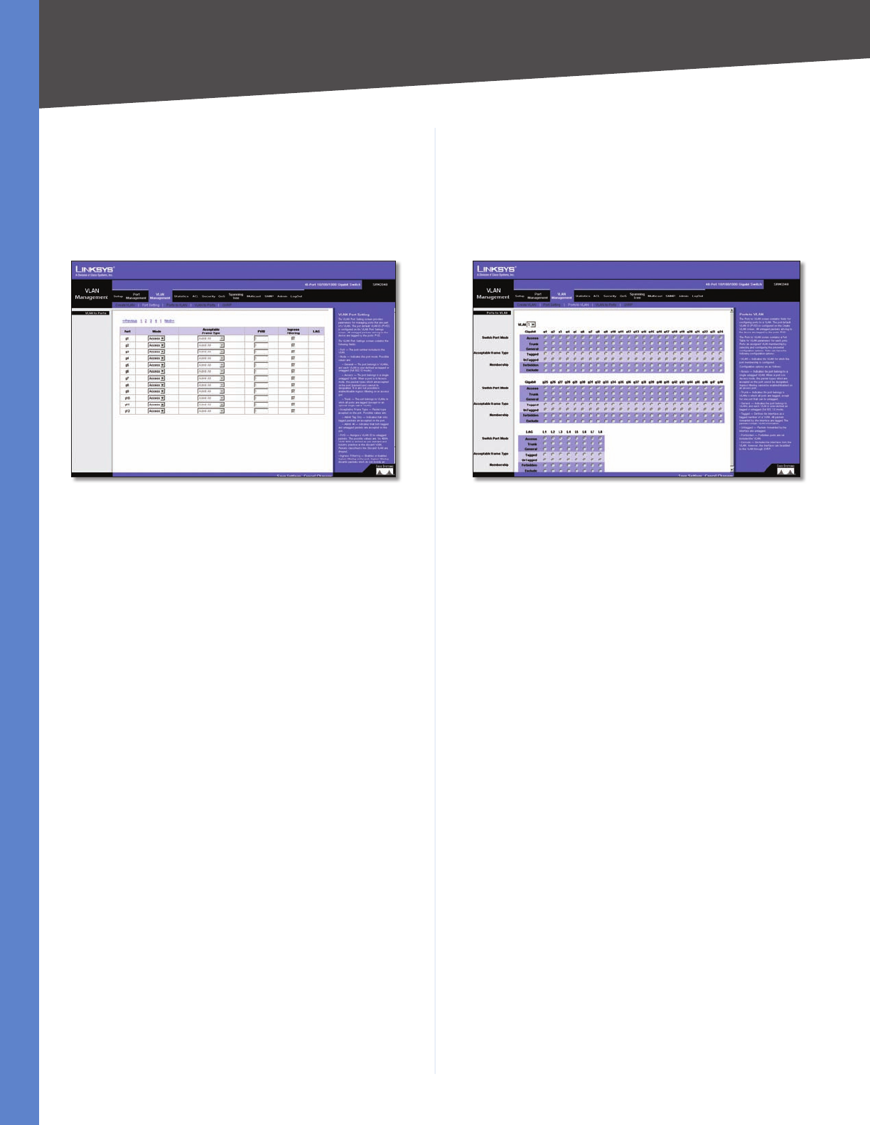
Chapter 5 Advanced Configuration
27
WebView Switches
VLAN Management > Port Setting
The VLAN Port Setting screen provides parameters for
managing ports that are part of a VLAN. The port default
VLAN ID (PVID) is configured on the VLAN Port Setting
screen. All untagged packets arriving to the device are
tagged by the ports PVID.
VLAN Management > Port Settings
Port The port number included in the VLAN.
Mode Indicates the port mode. Possible values are:
General •The port belongs to VLANs, and each VLAN
is user-defined as tagged or untagged (full 802.1Q
mode).
Access •The port belongs to a single untagged VLAN.
When a port is in Access mode, the packet types which
are accepted on the port (packet type) cannot be
designated. It is also not possible to enable or disable
ingress filtering on an access port.
Trunk •The port belongs to VLANs in which all ports are
tagged (except for an optional single native VLAN).
Acceptable Frame Type Packet type accepted on the
port. Possible values are:
Admit All •Indicates that both tagged and untagged
packets are accepted on the port.
Admit Tag Only •Indicates that only tagged packets
are accepted on the port.
PVID Assigns a VLAN ID to untagged packets. The
possible values are 2–4094. VLAN 4095 is defined as
per standard and industry practice as the discard VLAN.
Packets classified to the Discard VLAN are dropped.
Ingress Filtering Enables or disables Ingress filtering on
the port. Ingress filtering discards packets which do not
include an ingress port.
LAG Indicates the LAG to which the VLAN is defined.
VLAN Management > Ports to VLAN
The Ports to VLAN screen contains fields for configuring
ports to a VLAN. The port default VLAN ID (PVID) is
configured on the Create VLAN screen. All untagged
packets arriving to the device are tagged by the ports
PVID.
VLAN Management > Ports to VLAN
The Ports to VLAN screen contains a Port Table for VLAN
parameters for each port. Ports are assigned VLAN
membership by selecting and configuring the presented
configuration options.
VLAN The VLAN number.
Access Indicates the port belongs to a single untagged
VLAN. When a port is in Access mode, the packet types
which are accepted on the port cannot be designated.
Ingress filtering cannot be enabled or disabled on an
access port.
Trunk Indicates the port belongs to VLANs in which
all ports are tagged, except for one port that can be
untagged.
General Indicates the port belongs to VLANs, and each
VLAN is user-defined as tagged or untagged (full 802.1Q
mode).
Tagged Defines the interface as a tagged member of a
VLAN. All packets forwarded by the interface are tagged.
The packets contain VLAN information.
Untagged Packets forwarded by the interface are
untagged.
Forbidden Forbidden ports are not included in the
VLAN.
Exclude Excludes the interface from the VLAN. However,
the interface cannot be added to the VLAN through
GVRP.
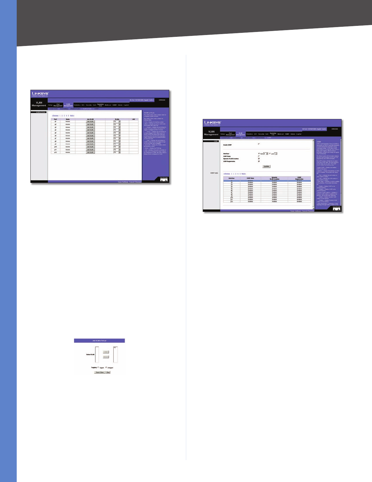
Chapter 5 Advanced Configuration
28
WebView Switches
VLAN Management > VLAN to Ports
The VLAN to Ports screen contains fields for configuring
VLANs to a ports.
VLAN Management > VLAN to Ports
Port Displays the interface number.
Mode Indicates the port-to-VLAN mode. The possible
field values are:
General •Indicates the port belongs to VLANs, and
each VLAN is user-defined as tagged or untagged (full
802.1Q mode).
Access •Indicates the port belongs to a single untagged
VLAN. When a port is in Access mode, the packet types
which are accepted on the port cannot be designated.
Ingress filtering cannot be enabled or disabled on an
access port.
Trunk •Indicates the port belongs to VLANs in which
all ports are tagged, except for one port that can be
untagged.
Join VLAN Defines the VLANs to which the interface is
joined.
VLAN to Ports > Join VLAN
VLANs Displays the PVID tag.
LAG Indicates if the port is a member of a LAG. If it is a
member of a LAG, it cannot be configured to a VLAN. The
LAG to which it belongs can be configured to a VLAN.
VLAN Management > GVRP
GARP VLAN Registration Protocol (GVRP) is specifically
provided for automatic distribution of VLAN membership
information among VLAN-aware bridges. GVRP allows
VLAN-aware bridges to automatically learn VLANs to
bridge ports mapping, without having to individually
configure each bridge and register VLAN membership.
VLAN Management > GVRP
The Global System LAG information displays the same
field information as the ports, but represents the LAG
GVRP information.
The GVRP screen is divided into two areas, GVRP and GVRP
Table. The field definitions for both areas are the same.
Enable GVRP Enables and disables GVRP on the device.
Interface Displays the interface on which GVRP is
enabled. The possible field values are:
Port •Indicates the port number on which GVRP is
enabled.
LAG •Indicates the LAG number on which GVRP is
enabled.
GVRP State Check this checkbox to enable GVRP on the
interface.
Dynamic VLAN Creation Check this checkbox to enable
Dynamic VLAN creation on the interface.
GVRP Registration Check this checkbox to enable VLAN
registration through GVRP on the device.
The Update button adds the configured GVRP setting to
the table at the bottom of the screen.
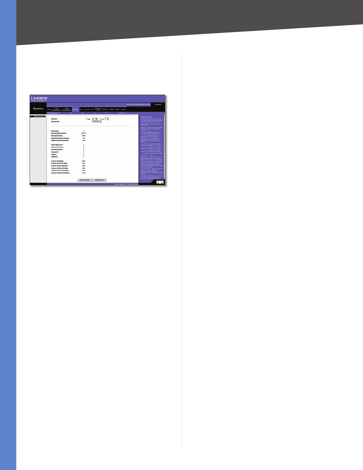
Chapter 5 Advanced Configuration
29
WebView Switches
Statistics > RMON Statistics
The RMON Statistics screen contains fields for viewing
information about device utilization and errors that
occurred on the device.
Statistics > RMON Statistics
Interface Indicates the device for which statistics are
displayed. The possible field values are:
Port •Defines the specific port for which RMON
statistics are displayed.
LAG •Defines the specific LAG for which RMON
statistics are displayed.
Refresh Rate Defines the amount of time that passes
before the interface statistics are refreshed. The possible
field values are:
No Refresh •Indicates that the RMON statistics are not
refreshed.
15 Sec •Indicates that the RMON statistics are refreshed
every 15 seconds.
30 Sec •Indicates that the RMON statistics are refreshed
every 30 seconds.
60 Sec •Indicates that the RMON statistics are refreshed
every 60 seconds.
Drop Events Displays the number of dropped events
that have occurred on the interface since the device was
last refreshed.
Received Bytes (Octets) Displays the number of octets
received on the interface since the device was last
refreshed. This number includes bad packets and Frame
Check Sequence (FCS) octets, but excludes framing bits.
Received Packets Displays the number of packets
received on the interface (including bad packets,
Multicast, and broadcast packets) since the device was
last refreshed.
Broadcast Packets Received Displays the number of
good broadcast packets received on the interface since
the device was last refreshed. This number does not
include Multicast packets.
Multicast Packets Received Displays the number of
good Multicast packets received on the interface since the
device was last refreshed.
CRC & Align Errors Displays the number of CRC and
Align errors that have occurred on the interface since the
device was last refreshed.
Undersize Packets Displays the number of undersized
packets (less than 64 octets) received on the interface
since the device was last refreshed.
Oversize Packets Displays the number of oversized
packets (over 1518 octets) received on the interface since
the device was last refreshed.
Fragments Displays the number of fragments (packets
with less than 64 octets, excluding framing bits, but
including FCS octets) received on the interface since the
device was last refreshed.
Jabbers Displays the total number of received packets
that were longer than 1518 octets. This number excludes
frame bits, but includes FCS octets that had either a bad
FCS with an integral number of octets (FCS Error) or a bad
FCS with a non-integral octet (Alignment Error) number.
The field range to detect jabbers is 20–150 ms.
Collisions Displays the number of collisions received on
the interface since the device was last refreshed.
Frames of xx Bytes Number of xx-byte frames received
on the interface since the device was last refreshed.
Clear Counters button This option will reset all of the
statistic counts.
Refresh Now button Use this option to refresh the
statistics that are displayed on the page.
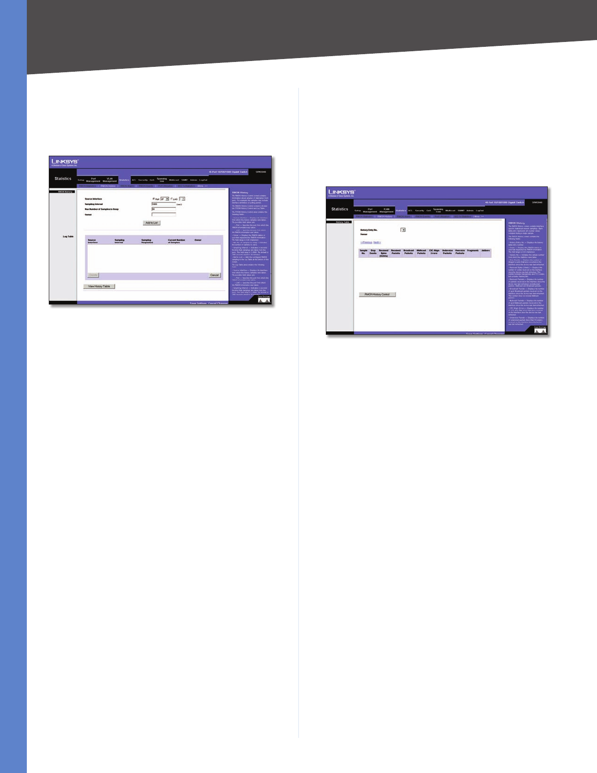
Chapter 5 Advanced Configuration
30
WebView Switches
Statistics > RMON History
The RMON History screen contains information about
samples of data taken from ports. For example, the samples
may include interface definitions or polling periods.
Statistics > RMON History
The RMON History Control screen is divided into RMON
History and Log Table.
Source Interface Displays the interface from which the
history samples were taken. The possible field values are:
Port •Specifies the port from which the RMON
information was taken.
LAG •Specifies the port from which the RMON
information was taken.
Sampling Interval Indicates (in seconds) the time
that samplings are taken from the ports. The field range
is 1–3600. The default is 1800 seconds (equal to 30
minutes).
Max No of Samples to Keep. Indicates the number of
samples to save.
Owner Displays the RMON station or user that
requested the RMON information. The field range is 0–20
characters.
The Add to List button adds the configured RMON
sampling to the Log Table at the bottom of the screen.
Log Table
Source Interface Displays the interface from which the
history samples were taken.
Sampling Interval Indicates the time in seconds that
samplings are taken from the port.
Sampling Requested Displays the number of samples to
be saved. The field range is 1–65,535. The default value is
50.
Current Number of Samples Displays the current
number of samples taken.
View History Table button This button opens the RMON
History screen.
RMON History
The RMON History screen contains interface-specific
statistical network samplings. Each table entry represents
all counter values compiled during a single sample.
RMON History Table
History Entry No Displays the history table entry
number.
Owner Displays the RMON station or user that requested
the RMON information. The field range is 0–20 characters.
Sample No Indicates the sample number from which the
statistics were taken.
Drop Events Displays the number of dropped events that
have occurred on the interface since the device was last
refreshed. This option is not available on the SRW224G4
and SRW248G4.
Received Bytes (Octets) Displays the number of octets
received on the interface since the device was last
refreshed. This number includes bad packets and FCS
octets, but excludes framing bits.
Received Packets Displays the number of packets
received on the interface since the device was last
refreshed, including bad packets, Multicast and Broadcast
packets.
Broadcast Packets Displays the number of good
Broadcast packets received on the interface since the
device was last refreshed. This number does not include
Multicast packets.
Multicast Packets Displays the number of good Multicast
packets received on the interface since the device was last
refreshed.
CRC Align Errors Displays the number of CRC and Align
errors that have occurred on the interface since the device
was last refreshed.
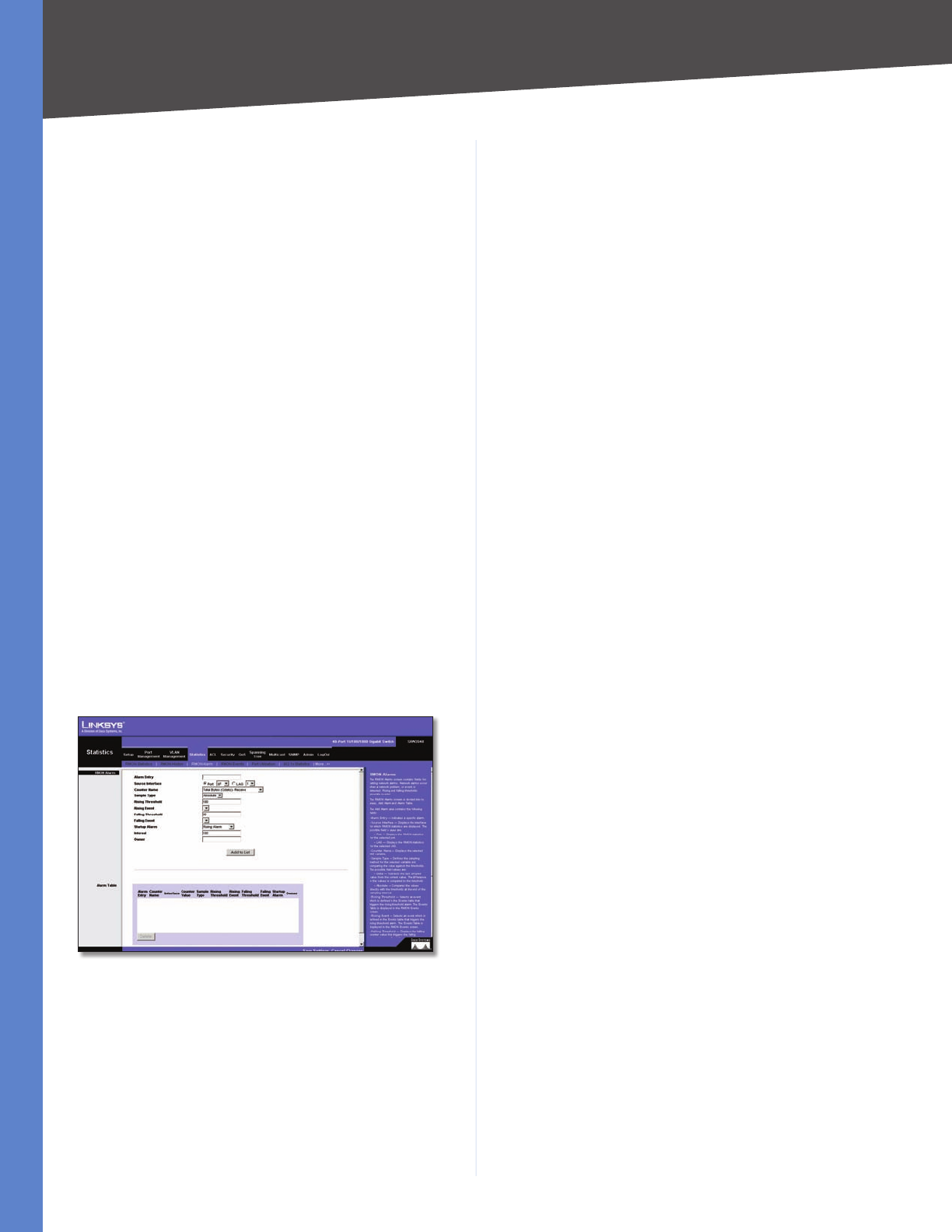
Chapter 5 Advanced Configuration
31
WebView Switches
Undersize Packets Displays the number of undersized
packets (less than 64 octets) received on the interface
since the device was last refreshed.
Oversize Packets Displays the number of oversized
packets (over 1518 octets) received on the interface since
the device was last refreshed.
Fragments Displays the number of fragments (packets
with less than 64 octets, excluding framing bits, but
including FCS octets) received on the interface since the
device was last refreshed.
Jabbers Displays the total number of received packets
that were longer than 1518 octets. This number excludes
frame bits, but includes FCS octets that had either a bad
Frame Check Sequence (FCS) with an integral number of
octets (FCS Error) or a bad FCS with a non-integral octet
(Alignment Error) number. The field range to detect
jabbers is 20–150 ms.
Collisions Displays the number of collisions received on
the interface since the device was last refreshed.
Utilization Displays the percentage of the interface
utilized.
Statistics > RMON Alarm
The RMON Alarm screen contains fields for setting network
alarms. Network alarms occur when a network problem, or
event, is detected. Rising and falling thresholds generate
events.
Statistics > RMON Alarm
Alarm Entry Indicates a specific alarm.
Source Interface Displays the interface for which RMON
statistics are displayed. The possible field values are:
Port •Displays the RMON statistics for the selected
port.
LAG •Displays the RMON statistics for the selected
LAG.
Counter Name Displays the selected MIB variable.
Sample Type Defines the sampling method for the
selected variable and comparing the value against the
thresholds. The possible field values are:
Absolute •Compares the values directly with the
thresholds at the end of the sampling interval.
Delta •Subtracts the last sampled value from the
current value. The difference in the values is compared
to the threshold.
Rising Threshold Displays the rising counter value that
triggers the rising threshold alarm. The rising threshold
is presented on top of the graph bars. Each monitored
variable is designated a color.
Rising Event Displays the mechanism in which the alarms
are reported. The possible field values are:
LOG •Indicates there is not a saving mechanism for
either the device or in the management system. If the
device is not reset, the entry remains in the Log Table.
TRAP •Indicates that an SNMP trap is generated, and
sent via the Trap mechanism. The Trap can also be
saved using the Trap mechanism.
Both •Indicates that both the Log and Trap mechanism
are used to report alarms.
Falling Threshold Displays the falling counter value that
triggers the falling threshold alarm. The falling threshold
is graphically presented on top of the graph bars. Each
monitored variable is designated a color.
Falling Event Displays the mechanism in which the
alarms are reported. The possible field values are:
LOG •Indicates there is not a saving mechanism for
either the device or in the management system. If the
device is not reset, the entry remains in the Log Table.
TRAP •Indicates that a SNMP trap is generated, and
sent via the Trap mechanism. The Trap can also be
saved using the Trap mechanism.
Both •Indicates that both the Log and Trap mechanism
are used to report alarms.
Startup Alarm Displays the trigger that activates the
alarm generation. Rising is defined by crossing the
threshold from a low-value threshold to a higher-value
threshold.
Interval Defines the alarm interval time in seconds.
Owner Displays the device or user that defined the
alarm.
Use the Add to List button to add the RMON Alarms Table
entry.
The Alarm Table area contains the following additional
field:
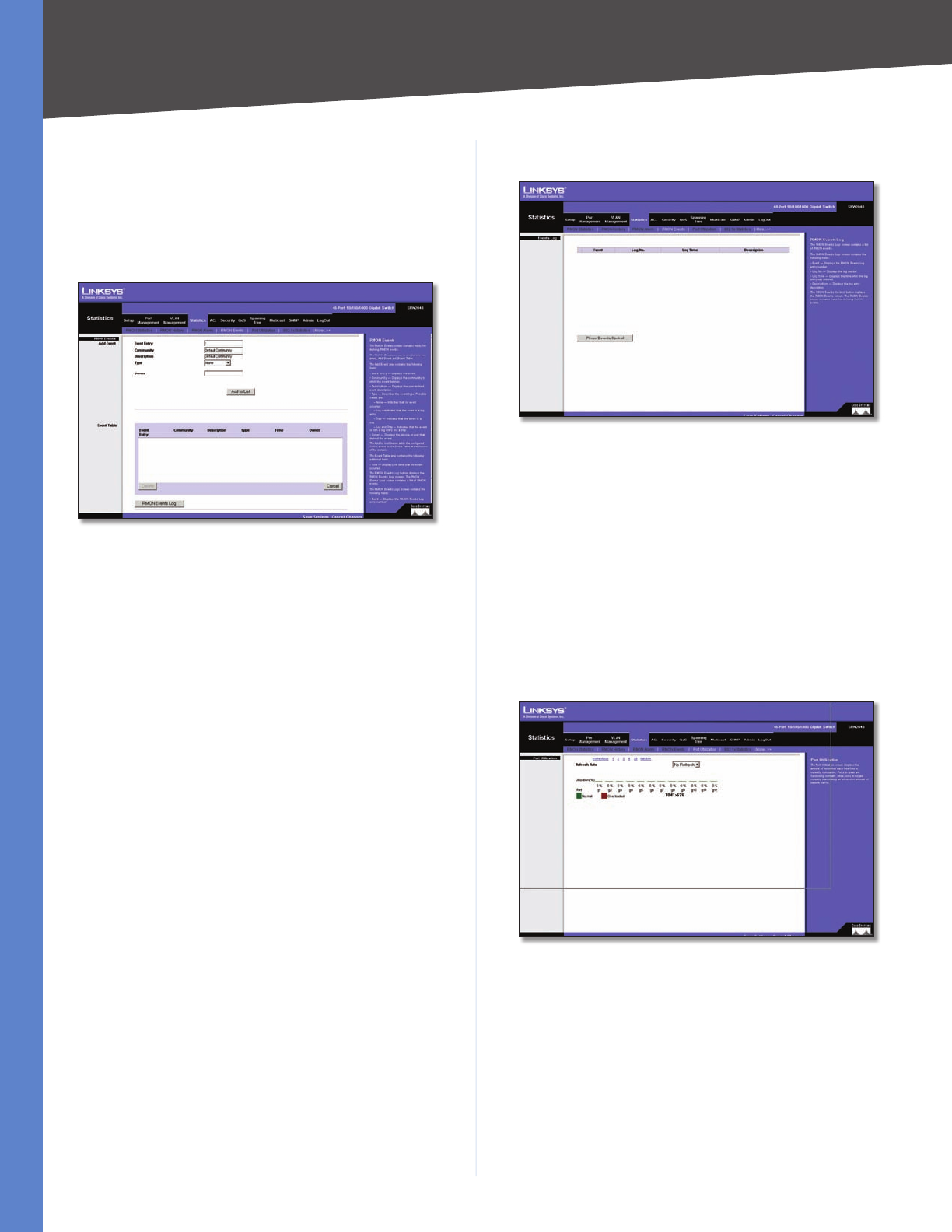
Chapter 5 Advanced Configuration
32
WebView Switches
Counter Value Displays the current counter value for the
particular alarm.
Statistics > RMON Events
The RMON Events screen contains fields for defining RMON
events.
Statistics > RMON Events
Add Event
Event Entry Displays the event.
Community Displays the community to which the event
belongs.
Description Displays the user-defined event description.
Type Describes the event type. Possible values are:
None •Indicates that no event occurred.
Log •Indicates that the event is a log entry.
Trap •Indicates that the event is a trap.
Log and Trap •Indicates that the event is both a log
entry and a trap.
Owner Displays the device or user that defined the
event.
Use the Add to List button to add the configured RMON
event to the Event Table at the bottom of the screen.
The Event Table area contains the following additional
field:
Time Displays the time that the event occurred.
RMON Events Log
RMON Events > Events Log
Event Displays the RMON events log entry number.
Log No Displays the log number.
Log Time Displays the time the log entry was entered.
Description Displays the log entry description.
Statistics > Port Utilization
The Port Utilization screen displays the amount of resources
each interface is currently consuming. Ports in green are
functioning normally, while ports in red are currently
transmitting an excessive amount of network traffic.
Statistics > Port Utilization
Refresh Rate Indicates the amount of time that passes
before the port utilization statistics are refreshed. The
possible field values are:
No Refresh •Statistics are not refreshed.
15 Sec •Statistics are refreshed every 15 seconds.
30 Sec •Statistics are refreshed every 30 seconds.
60 Sec •Statistics are refreshed every 60 seconds.
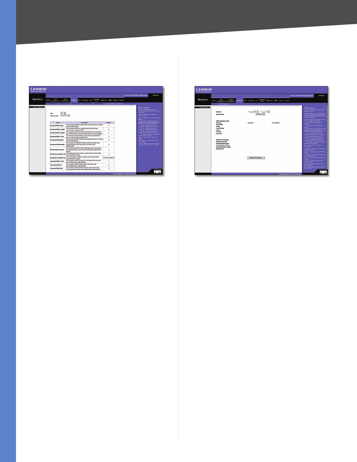
Chapter 5 Advanced Configuration
33
WebView Switches
Statistics > 802.1x Statistics
The 802.1X Statistic screen contains information about
EAP packets received on a specific port.
Statistics > 802.1x Statistics
Port Indicates the port, which is polled for statistics.
Refresh Rate Indicates the amount of time that passes
before the EAP statistics are refreshed. The possible field
values are:
No Refresh •Indicates that the EAP statistics are not
refreshed.
15 Sec •Indicates that the EAP statistics are refreshed
every 15 seconds.
30 Sec •Indicates that the EAP statistics are refreshed
every 30 seconds.
60 Sec •Indicates that the EAP statistics are refreshed
every 60 seconds.
Name Displays the measured 802.1x statistic.
Description Describes the measured 802.1x statistic.
Packet Displays the amount of packets measured for the
particular 802.1x statistic.
Statistics > GVRP Statistics
The GVRP Statistics screen contains device statistics for
GVRP.
Statistics > GVRP Statistics
The GVRP Statistics screen is divided into two areas,
GVRP Statistics Table and GVRP Error Statistics Table. The
following fields are relevant for both tables:
Interface Specifies the interface type for which the
statistics are displayed.
Port •Indicates port statistics are displayed.
LAG •Indicates LAG statistics are displayed.
Refresh Rate Indicates the amount of time that passes
before the GVRP statistics are refreshed. The possible field
values are:
No Refresh •Indicates that the GVRP statistics are not
refreshed.
15 Sec •Indicates that the GVRP statistics are refreshed
every 15 seconds.
30 Sec •Indicates that the GVRP statistics are refreshed
every 30 seconds.
60 Sec •Indicates that the GVRP statistics are refreshed
every 60 seconds.
The GVRP Statistics Table contains the following fields:
Join Empty Displays the device GVRP Join Empty
statistics.
Empty Displays the device GVRP Empty statistics.
Leave Empty Displays the device GVRP Leave Empty
statistics.
Join In Displays the device GVRP Join In statistics.
Leave In Displays the device GVRP Leave in statistics.
Leave All Displays the device GVRP Leave all statistics.

Chapter 5 Advanced Configuration
34
WebView Switches
The GVRP Error Statistics Table contains the following
fields:
Invalid Protocol ID Displays the device GVRP Invalid
Protocol ID statistics.
Invalid Attribute Type Displays the device GVRP Invalid
Attribute ID statistics.
Invalid Attribute Value Displays the device GVRP Invalid
Attribute Value statistics.
Invalid Attribute Length Displays the device GVRP
Invalid Attribute Length statistics.
Invalid Event Displays the device GVRP Invalid Events
statistics.
Use the Clear All Counters button to reset all tables.
ACL > IP Based ACL
The IP Based ACL (Access Control List) screen contains
information for defining IP-based Access Control Lists
(ACLs).
ACL > IP Based ACL
ACL Name Displays the user-defined IP based ACLs.
New ACL Name Define a new user-defined IP based ACL,
the name cannot include spaces.
Delete ACL Deletes the selected ACL.
Action Indicates the action assigned to the packet
matching the ACL. Packets are forwarded or dropped. In
addition, the port can be shut down, a trap can be sent
to the network administrator, or a packet assigned rate
limiting restrictions for forwarding. The options are as
follows:
Permit •Forwards packets which meet the ACL
criteria.
Deny •Drops packets which meet the ACL criteria.
Shutdown •Drops packet that meets the ACL
criteria, and disables the port to which the packet
was addressed. Ports are reactivated from the Port
Management screen.
Protocol Creates an Access Control Entry (ACE) based on
a specific protocol.
Select from List •Selects from a protocols list on which
ACE can be based. The possible field values are:
Any •Matches the protocol to any protocol.
EIGRP •Indicates that the Enhanced Interior
Gateway Routing Protocol (EIGRP) is used to classify
network flows.
ICMP •Indicates that the Internet Control Message
Protocol (ICMP) is used to classify network flows.
IGMP •Indicates that the Internet Group
Management Protocol (IGMP) is used to classify
network flows.
TCP •Indicates that the Transmission Control
Protocol is used to classify network flows.
OSPF •Matches the packet to the Open Shortest
Path First (OSPF) protocol.
UDP •Indicates that the User Datagram Protocol is
used to classify network flows.
Protocol ID To Match •Adds user-defined protocols to
which packets are matched to the ACE. Each protocol
has a specific protocol number which is unique. The
possible field range is 0–255.
TCP Flags Filters packets by TCP flag. Filtered packets
are either forwarded or dropped. Filtering packets by TCP
flags increases packet control, which increases network
security. The values that can be assigned are:
Set •Enables filtering packets by selected flags.
Unset •Disables filtering packets by selected flags.
Don’t care •Indicates that selected packets do not
influence the packet filtering process.
The TCP Flags that can be selected are:
Urg •Indicates the packet is urgent.
Ack •Indicates the packet is acknowledged.
Psh •Indicates the packet is pushed.
Rst •Indicates the connection is dropped.
Syn •Indicates request to start a session.
Fin •Indicates request to close a session.
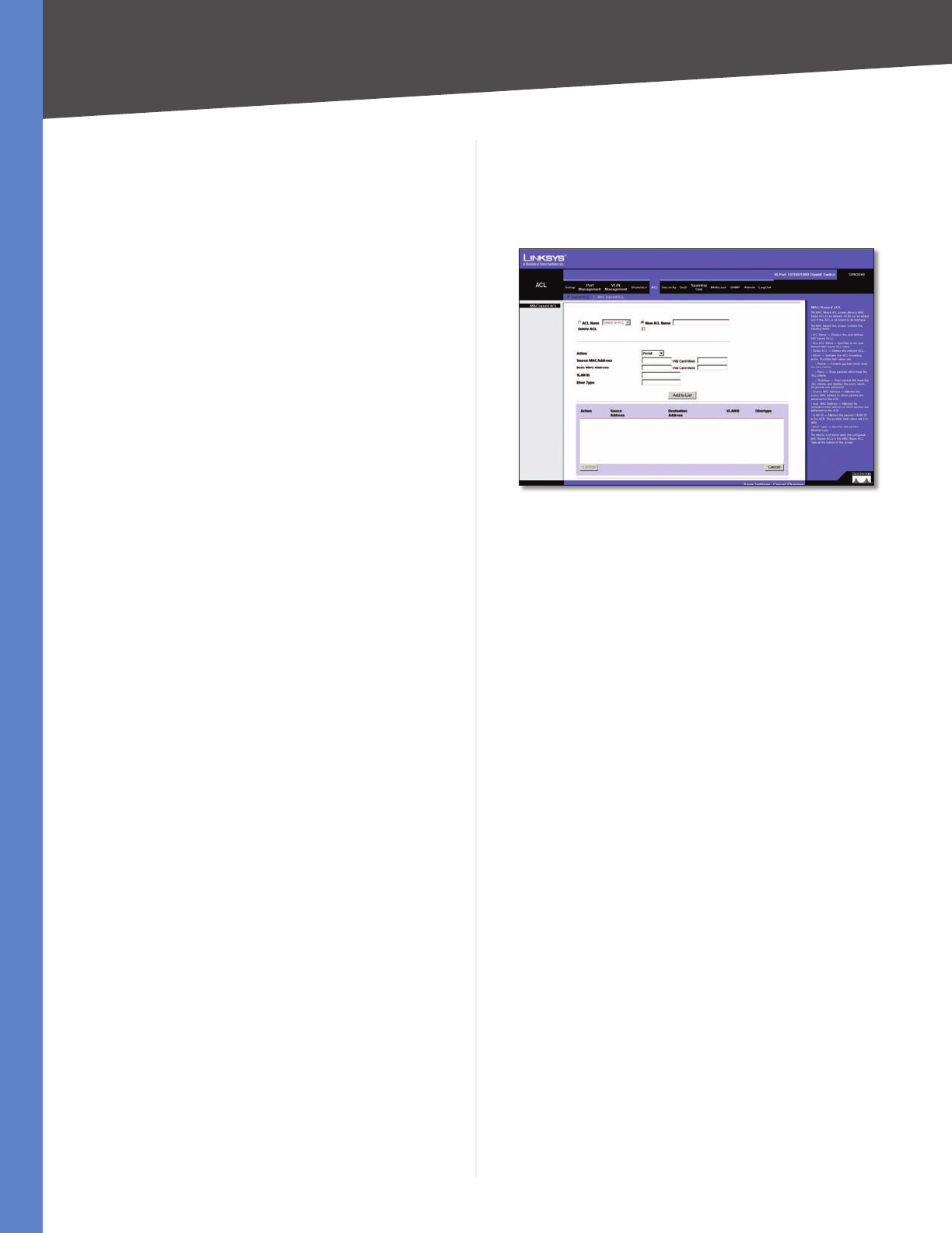
Chapter 5 Advanced Configuration
35
WebView Switches
Source Port Defines the TCP/UDP source port to which
the ACE is matched. This field is active only if 800/6-TCP or
800/17-UDP are selected in the Select from List drop-down
menu. The possible field range is 0–65,535.
Destination Port Defines the TCP/UDP destination
port. This field is active only if 800/6-TCP or 800/17-UDP
are selected in the Select from List drop-down menu. The
possible field range is 0–65,535.
Source IP Address Matches the source port IP address to
which packets are addressed to the ACE.
Wildcard Mask •Defines the source IP address
wildcard mask. Wildcard masks specify which bits
are used and which bits are ignored. A wild card
mask of 255.255.255.255 indicates that no bit is
important. A wildcard of 0.0.0.0 indicates that all
the bits are important. For example, if the source IP
address 149.36.184.198 and the wildcard mask is
255.36.184.00, the first eight bits of the IP address are
ignored, while the last eight bits are used.
Dest. IP Address Matches the destination port IP address
to which packets are addressed to the ACE.
Wildcard Mask •Defines the destination IP address
wildcard mask.
Match DSCP Matches the packet DSCP value to the ACE.
Either the DSCP value or the IP Precedence value is used to
match packets to ACLs. The possible field range is 0–63.
Match IP Precedence Matches the packet IP Precedence
value to the ACE. Either the DSCP value or the IP Precedence
value is used to match packets to ACLs. The possible field
range is 0–7.
The Add to List button adds the configured IP Based ACLs
to the IP Based ACL Table at the bottom of the screen.
ACL > MAC Based ACL
The MAC Based ACL screen allows a MAC based ACL to be
defined. ACEs can be added only if the ACL is not bound
to an interface.
ACL > Mac Based ACL
ACL Name Displays the user-defined MAC based ACLs.
New ACL Name Specifies a new user-defined MAC based
ACL name, the name cannot include spaces.
Delete ACL Deletes the selected ACL.
Action Indicates the ACL forwarding action. Possible field
values are:
Permit •Forwards packets which meet the ACL
criteria.
Deny •Drops packets which meet the ACL criteria.
Shutdown •Drops packet that meet the ACL criteria,
and disables the port to which the packet was
addressed.
Source MAC Address Matches the source MAC address
to which packets are addressed to the ACE.
Wildcard Mask •Defines the source IP address
wildcard mask. Wildcard masks specify which bits
are used and which bits are ignored. A wild card
mask of 255.255.255.255 indicates that no bit is
important. A wildcard of 0.0.0.0 indicates that all
the bits are important. For example, if the source IP
address 149.36.184.198 and the wildcard mask is
255.36.184.00, the first eight bits of the IP address are
ignored, while the last eight bits are used.
Dest. MAC Address Matches the destination MAC
address to which packets are addressed to the ACE.
Wildcard Mask •Defines the destination IP address
wildcard mask.
VLAN ID Matches the packet’s VLAN ID to the ACE. The
possible field values are 2–4094.
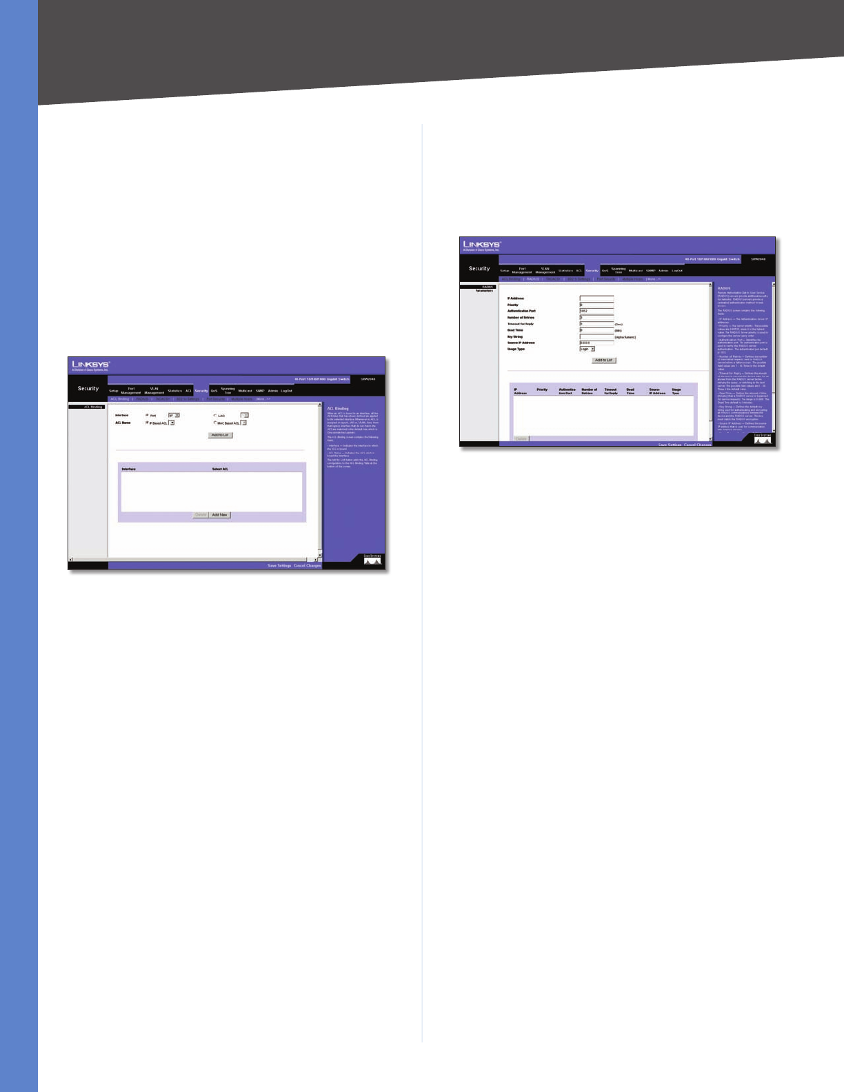
Chapter 5 Advanced Configuration
36
WebView Switches
Ether Type Specifies the packet’s Ethernet type.
Use the Add to List button to add the configured MAC
Based ACLs to the MAC Based ACL Table at the bottom of
the screen.
Security > ACL Binding
When an ACL is bound to an interface, all the ACE rules
that have been defined are applied to the selected
interface. Whenever an ACL is assigned on a port, LAG or,
VLAN, flows from that ingress interface that do not match
the ACL are matched to the default rule, which is Drop
unmatched packets.
Security > ACL Binding
Interface Indicates the interface to which the ACL is
bound.
ACL Name Indicates the ACL which is bound to the
interface.
Use the Add to List button to add the ACL Binding
configuration to the ACL Binding Table at the bottom of
the screen.
Security > RADIUS
Remote Authorization Dial-In User Service (RADIUS)
servers provide additional security for networks. RADIUS
servers provide a centralized authentication method for
web access.
Security > RADIUS
IP Address The Authentication Server IP address.
Priority The server priority. The possible values are
0–65,535, where 1 is the highest value. The RADIUS Server
priority is used to configure the server query order.
Authentication Port Identifies the authentication port.
The authentication port is used to verify the RADIUS server
authentication. The authenticated port default is 1812.
Number of Retries Defines the number of transmitted
requests sent to RADIUS server before a failure occurs. The
possible field values are 1–10. The default value is 3.
Timeout for Reply Defines the amount of the time in
seconds the device waits for an answer from the RADIUS
server before retrying the query, or switching to the next
server. The possible field values are 1–30. The default
value is 3.
Dead Time Defines the amount of time (minutes) that a
RADIUS server is bypassed for service requests. The range
is 0–2000. The Dead Time default is 0 minutes.
Key String Defines the default key string used for
authenticating and encrypting all RADIUS communications
between the device and the RADIUS server. This key must
match the RADIUS encryption.
Source IP Address Defines the source IP address that is
used for communication with RADIUS servers.
Usage Type Specifies the RADIUS server authentication
type. The default value is Login. The possible field values
are:
Login •Indicates that the RADIUS server is used for
authenticating user name and passwords.
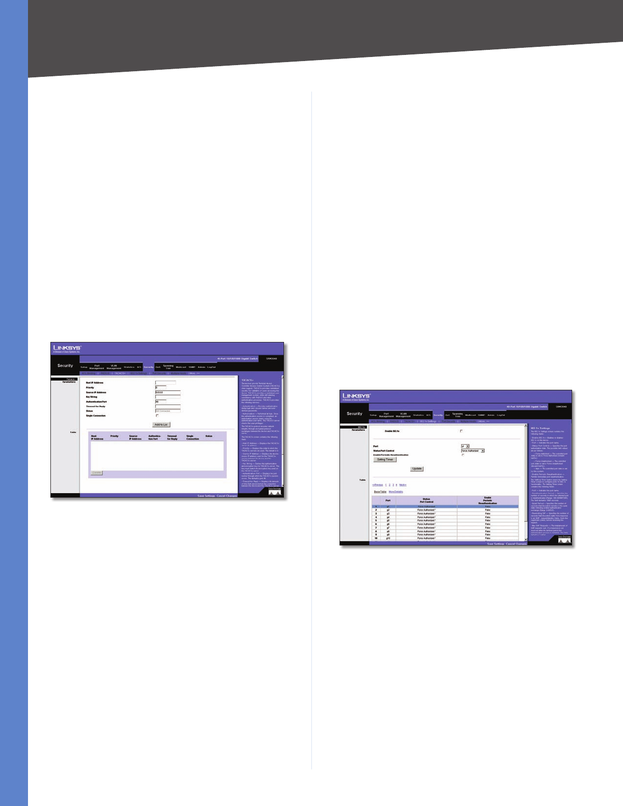
Chapter 5 Advanced Configuration
37
WebView Switches
802.1X •Indicates that the RADIUS server is used for
802.1X authentication.
All •Indicates that the RADIUS server is used for
authenticating user name and passwords, and 802.1X
port authentication.
Use the Add to List button to add the RADIUS configuration
to the RADIUS Table at the bottom of the screen.
Security > TACACS+
The device provides Terminal Access Controller Access
Control System (TACACS+) client support. TACACS+
provides centralized security for validation of users
accessing the device. TACACS+ provides a centralized user
management system, while still retaining consistency with
RADIUS and other authentication processes. The TACACS+
protocol ensures network integrity through encrypted
protocol exchanges between the device and TACACS+
server.
Security > TACACS+
Host IP Address Displays the TACACS+ Server IP
address.
Priority Displays the order in which the TACACS+ servers
are used. The default is 0.
Source IP Address Displays the device source IP address
used for the TACACS+ session between the device and the
TACACS+ server.
Key String Defines the authentication and encryption key
for TACACS+ server. The key must match the encryption
key used on the TACACS+ server.
Authentication Port Displays the port number through
which the TACACS+ session occurs. The default is port 49.
Timeout for Reply Displays the amount of time that
passes before the connection between the device and
the TACACS+ server times out. The field range is 1–30
seconds.
Status Displays the connection status between the
device and the TACACS+ server. The possible field values
are:
Connected •There is currently a connection between
the device and the TACACS+ server.
Not Connected •There is not currently a connection
between the device and the TACACS+ server.
Single Connection Maintains a single open connection
between the device and the TACACS+ server when
selected
Use the Add to List button to add the TACACS+
configuration to the TACACS+ table at the bottom of the
screen.
Security > 802.1x Settings
Port based authentication enables authenticating system
users on a per-port basis via an external server. Only
authenticated and approved system users can transmit
and receive data. Ports are authenticated via the RADIUS
server using the Extensible Authentication Protocol
(EAP).
Security > 802.1x Settings
Enable 802.1x Select the checkbox to enable 802.1x
authentication.
Port Indicates the port name.
Status Port Control Specifies the port authorization
state. The possible field values are as follows:
Force-Unauthorized •The controlled port state is set
to Force-Unauthorized (discard traffic).
Auto •The controlled port state is set by the system.
Force-Authorized •The controlled port state is set to
Force-Authorized (forward traffic).
Enable Periodic Reauthentication Permits immediate
port reauthentication.
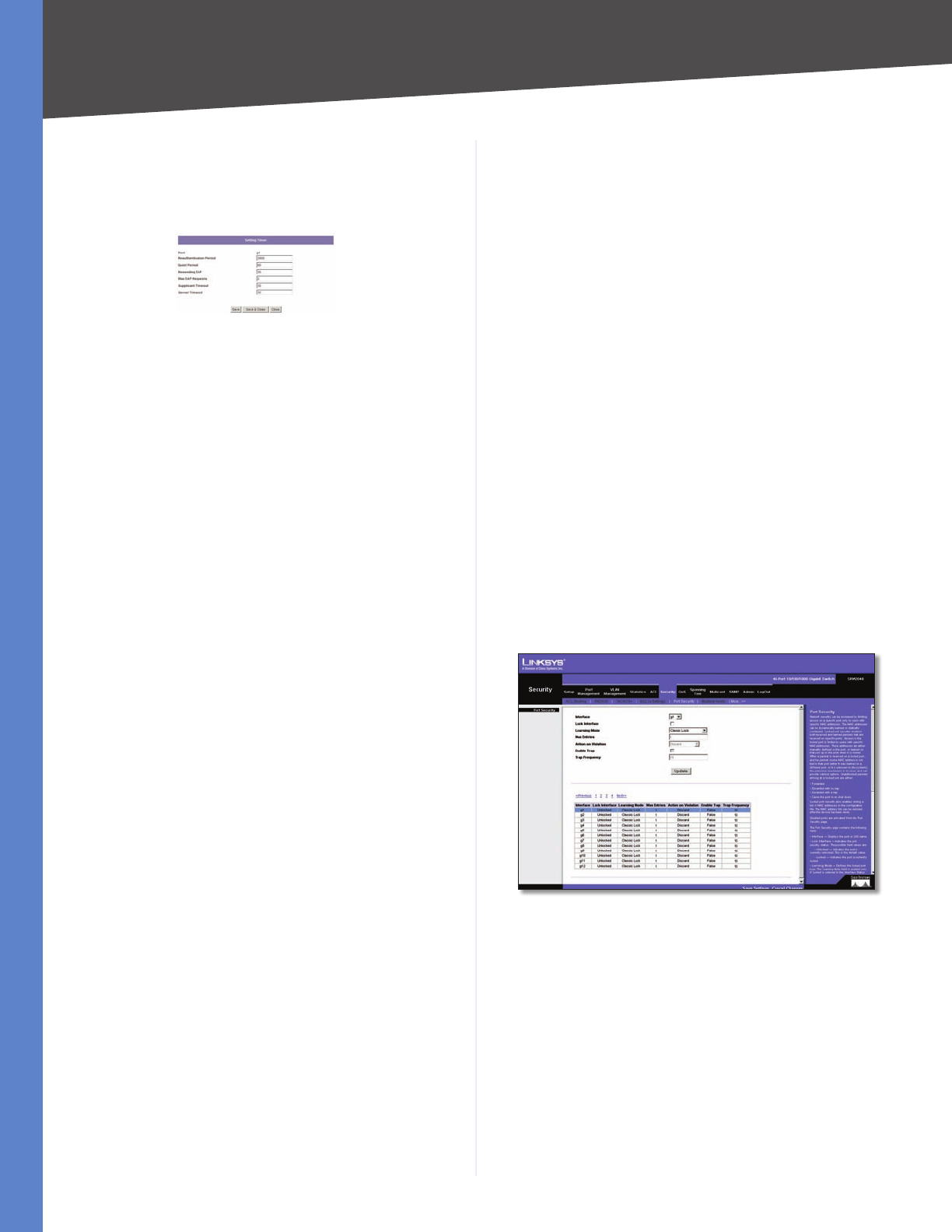
Chapter 5 Advanced Configuration
38
WebView Switches
Use the Setting Timer button to open the Setting Timer
screen to configure ports for 802.1x functionality.
802.1x Settings > Setting Timer
802.1x Settings > Setting Timer
Port Indicates the port name.
Reauthentication Period Specifies the number of
seconds in which the selected port is reauthenticated
(Range: 300–4,294,967,295). The field default is 3600
seconds.
Quiet Period Specifies the number of seconds that
the switch remains in the quiet state following a failed
authentication exchange (Range: 0–65,535).
Resending EAP Specifies the number of seconds that the
switch waits for a response to an EAP - request/identity
frame, from the supplicant (client), before resending the
request.
Max EAP Requests Displays the total amount of EAP
requests sent. If a response is not received after the
defined period, the authentication process is restarted.
The field default is 2 retries.
Supplicant Timeout Displays the number of seconds that
lapses before EAP requests are resent to the supplicant
(Range: 1–65,535). The field default is 30 seconds.
Server Timeout Specifies the number of seconds
(1–65,535) that lapses before the switch resends a request
to the authentication server. The default is 30 seconds.
Security > Port Security
Network security can be increased by limiting access on
a specific port only to users with specific MAC addresses.
MAC addresses can be dynamically learned or statically
configured. Locked port security monitors both received
and learned packets that are received on specific ports.
Access to the locked port is limited to users with specific
MAC addresses. These addresses are either manually
defined on the port, or learned on that port up to the
point when it is locked. When a packet is received on a
locked port, and the packet source MAC address is not tied
to that port (either it was learned on a different port, or it
is unknown to the system), the protection mechanism is
invoked, and can provide various options. Unauthorized
packets arriving at a locked port are either:
Forwarded •
Discarded with no trap •
Discarded with a trap •
Cause the port to be shut down. •
Locked port security also enables storing a list of MAC
addresses in the configuration file. The MAC address list
can be restored after the device has been reset.
Disabled ports are activated from the Port Security page.
Security > Port Security
Interface Displays the port or LAG name.
Lock Interface Selecting this option locks the specified
interface.
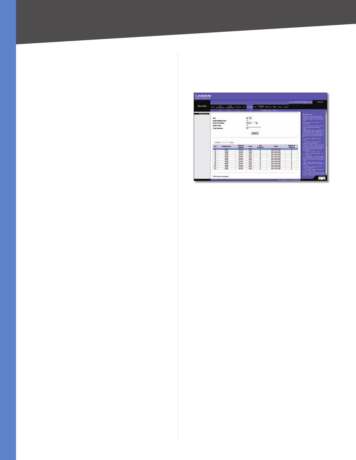
Chapter 5 Advanced Configuration
39
WebView Switches
Learning Mode Defines the locked port type. The
Learning Mode field is enabled only if Locked is selected
in the Interface Status field. The possible field values are:
Classic Lock •Locks the port using the classic lock
mechanism. The port is immediately locked, regardless
of the number of addresses that have already been
learned.
Limited Dynamic Lock •Locks the port by deleting
the current dynamic MAC addresses associated with
the port. The port learns up to the maximum addresses
allowed on the port. Both relearning and aging MAC
addresses are enabled.
In order to change the Learning Mode, the Lock Interface
must be set to Unlocked. Once the mode is changed, the
Lock Interface can be reinstated.
Max Entries Specifies the number of MAC addresses that
can be learned on the port. The Max Entries field is enabled
only if Locked is selected in the Interface Status field. In
addition, the Limited Dynamic Lock mode is selected. The
default is 1.
Action on Violation Indicates the action to be applied to
packets arriving on a locked port. The possible field values
are:
Discard •Discards packets from any unlearned source.
This is the default value.
Forward Normal •Forwards packets from an unknown
source without learning the MAC address.
Discard Disable •Discards packets from any unlearned
source and shuts down the port. The port remains shut
down until reactivated, or until the device is reset.
Enable Trap Enables traps when a packet is received on
a locked port.
Trap Frequency The amount of time (in seconds)
between traps. The default value is 10 seconds.
Security > Multiple Hosts
The Multiple Hosts screen allows network managers to
configure advanced port-based authentication settings
for specific ports and VLANs.
Security > Multiple Hosts
Port Displays the port number for which advanced port-
based authentication is enabled.
Enable Multiple Hosts When checked, indicates that
multiple hosts are enabled. Multiple hosts must be
enabled in order to either disable the ingress-filter, or to
use port-lock security on the selected port.
Action on Violation Defines the action to be applied to
packets arriving in single-host mode, from a host whose
MAC address is not the supplicant MAC address. The
possible field values are:
Discard •Discards the packets. This is the default
value.
Forward •Forwards the packet.
Discard Disable •Discards the packets and shuts
down the port. The ports remains shut down until
reactivated, or until the device is reset.
Enable Traps When checked, indicates that traps are
enabled for Multiple Hosts.
Trap Frequency Defines the time period by which traps
are sent to the host. The Trap Frequency (1–1,000,000)
field can be defined only if multiple hosts are disabled.
The default is 10 seconds.
The table contains the following additional fields:
Status Indicates the host status. If there is an asterisk (*),
the port is either not linked or is down. The possible field
values are:
Number of Violations Indicates the number of packets
that arrived on the interface in single-host mode, from
a host whose MAC address is not the supplicant MAC
address.
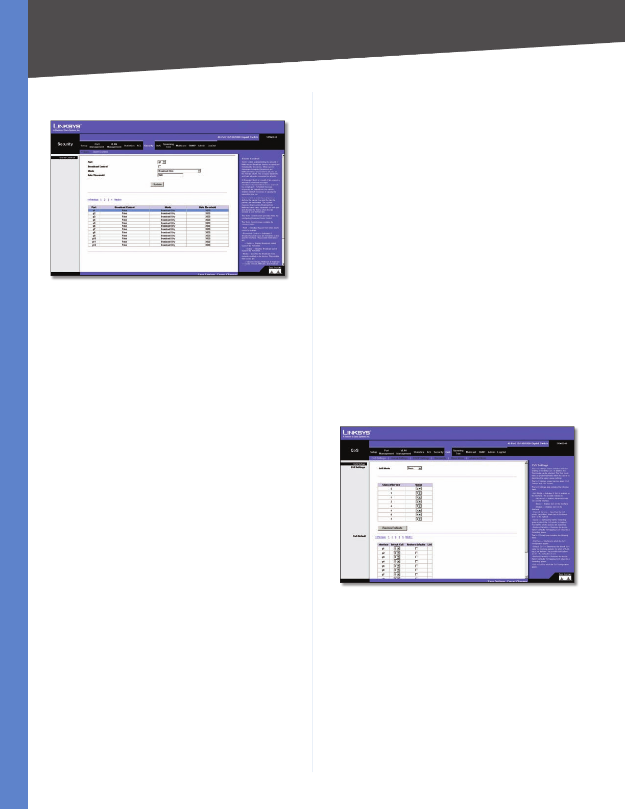
Chapter 5 Advanced Configuration
40
WebView Switches
Security > Storm Control
Security > Storm Control
Port Displays the port number for which storm control is
enabled.
Broadcast Control Indicates whether broadcast packet
types are forwarded on the specific interface.
Mode Specifies the Broadcast mode currently enabled
on the device. The possible field values are:
Unknown Unicast, Multicast & Broadcast •Counts
Unicast, Multicast, and Broadcast traffic. This option is
not available on the SRW224G4 and SRW248G4.
Multicast & Broadcast •Counts Broadcast and
Multicast traffic together.
Broadcast Only •Counts only Broadcast traffic.
Rate Threshold The maximum rate (packets per second)
at which unknown packets are forwarded. The default
value is 3500. The range is 70–100,000.
QoS
Network traffic is usually unpredictable, and the only
basic assurance that can be offered is best effort traffic
delivery. To overcome this challenge, Quality of Service
(QoS) is applied throughout the network. This ensures that
network traffic is prioritized according to specified criteria,
and that specific traffic receives preferential treatment.
QoS in the network optimizes network performance and
entails two basic facilities:
Classifying incoming traffic into handling classes, based
on an attribute, including:
The ingress interface •
Packet content •
A combination of these attributes •
Providing various mechanisms for determining the
allocation of network resources to different handling
classes, including:
The assignment of network traffic to a particular •
hardware queue
The assignment of internal resources •
Traffic shaping •
The terms Class of Service (CoS) and QoS are used in the
following context:
CoS provides varying Layer 2 traffic services. CoS refers to
classification of traffic to traffic-classes, which are handled
as an aggregate whole, with no per-flow settings. CoS is
usually related to the 802.1p service that classifies flows
according to their Layer 2 priority, as set in the VLAN
header.
QoS refers to Layer 2 traffic and above. QoS handles per-
flow settings, even within a single traffic class.
QoS > CoS Settings
The CoS Settings screen contains fields for enabling or
disabling CoS. In addition, the Trust mode can be selected.
The Trust mode relies on predefined fields within the
packet to determine the egress queue settings.
QoS > CoS Settings
The CoS Settings screen has two areas, CoS Settings and
CoS to Queue.
QoS Mode Indicates if QoS is enabled on the interface.
The possible values are:
Disable •Disables QoS on the interface.
Basic •Enables QoS on the interface.
Advanced •Enables Advanced mode QoS on the
interface. This feature has been added to version
1.2 of the SRW2024/SRW2016 and version 1.1 of the
SRW224G4/SRW248G4.
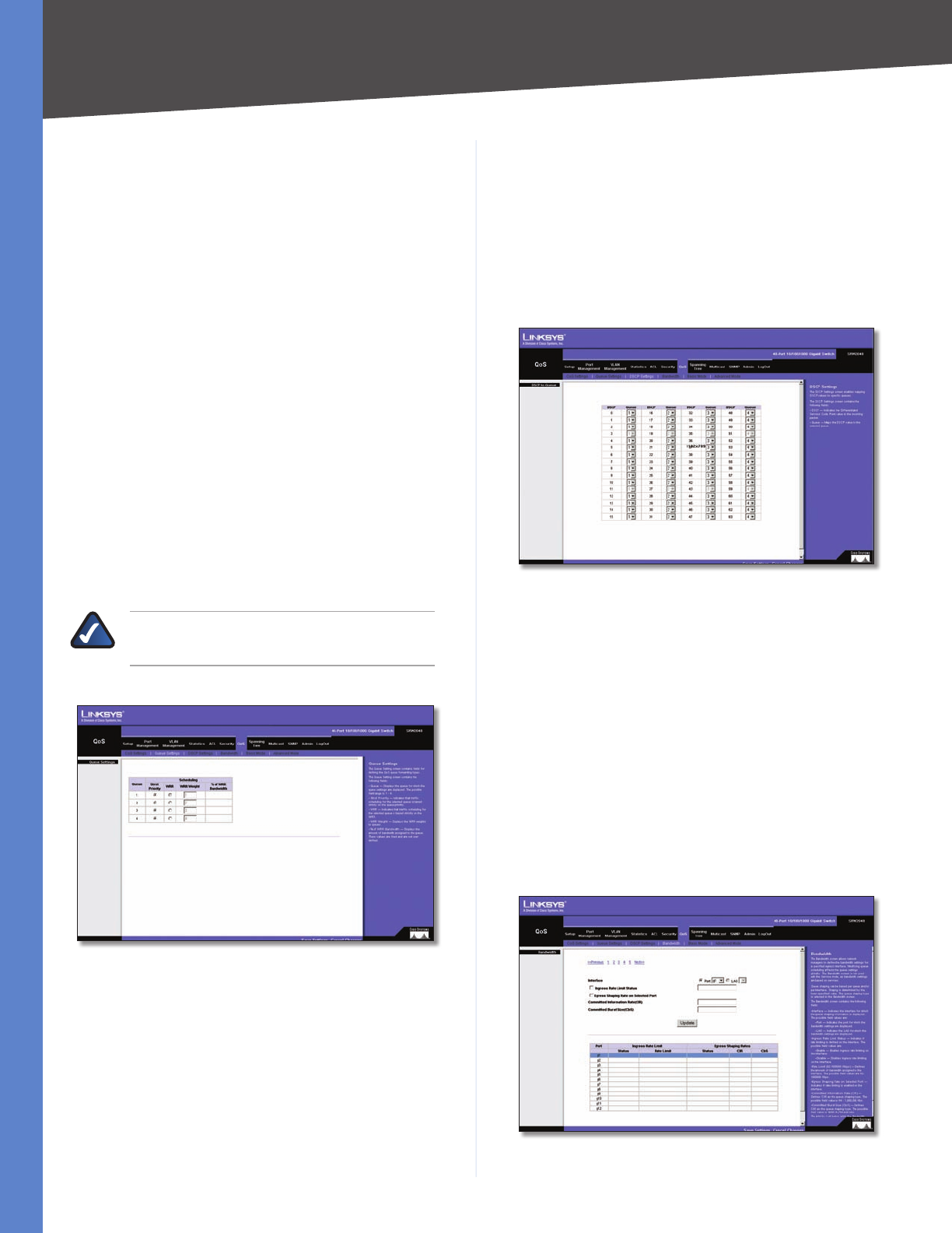
Chapter 5 Advanced Configuration
41
WebView Switches
Class of Service Specifies the CoS priority tag values,
where 0 is the lowest and 7 is the highest.
Queue Defines the traffic forwarding queue to which the
CoS priority is mapped. Four traffic priority queues are
supported.
The Restore Defaults button restores the device factory
defaults for mapping CoS values to a forwarding queue.
CoS Default
Interface Interface to which the CoS configuration
applies.
Default CoS Determines the default CoS value for
incoming packets for which a VLAN tag is not defined. The
possible field values are 0–7. The default CoS is 0.
Restore Defaults Restores the device factory defaults for
mapping CoS values to a forwarding queue.
LAG LAG to which the CoS configuration applies.
QoS > Queue Settings
The Queue Setting screen contains fields for defining the
QoS queue forwarding types.
NOTE: Individual queues cannot be assigned
on the SRW224G4 and SRW248G4.
QoS > Queue Settings
Queue Displays the queue for which the queue settings
are displayed. The range is 1–4.
Strict Priority Indicates that traffic scheduling for the
selected queue is based strictly on the queue priority.
WRR Indicates that traffic scheduling for the selected
queue is based strictly on weighted round-robin (WRR).
WRR Weight Displays the WRR weights to queues.
% of WRR Bandwidth Displays the amount of bandwidth
assigned to the queue. These values are fixed and are not
user defined.
QoS > DSCP Settings
The DSCP Settings screen enables mapping DSCP values to
specific queues.
QoS > DSCP Settings
The DSCP Settings screen contains the following fields:
DSCP Indicates the Differentiated Services Code Point
value in the incoming packet.
Queue Maps the DSCP value to the selected queue.
QoS > Bandwidth
The Bandwidth screen allows network managers to define
the bandwidth settings for a specified egress interface.
Modifying queue scheduling affects the queue settings
globally. The Bandwidth screen is not used with the Service
mode, as bandwidth settings are based on services. This
feature has been added to version 1.2 of the SRW2024/
SRW2016 and version 1.1 of the SRW224G4/SRW248G4.
QoS > Bandwidth
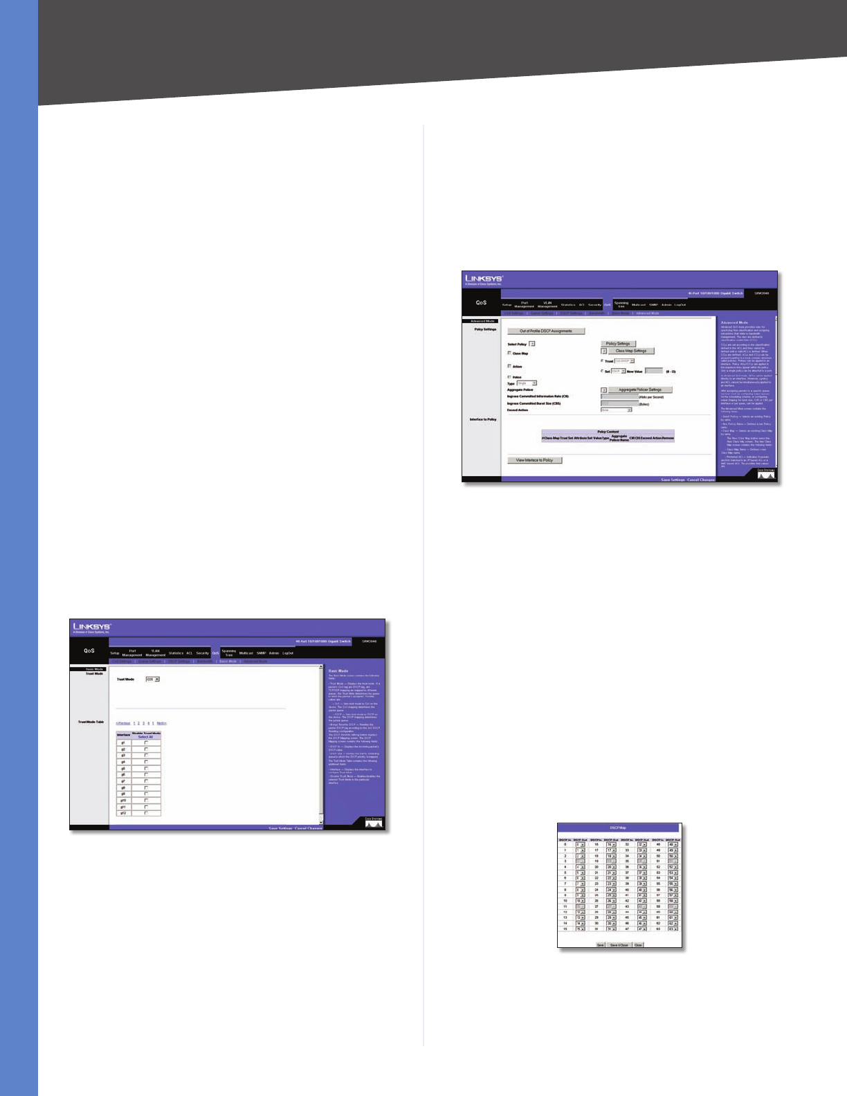
Chapter 5 Advanced Configuration
42
WebView Switches
Queue shaping can be based per queue and/or per
interface. Shaping is determined by the lower specified
value. The queue shaping type is selected in the Bandwidth
screen.
Interface Indicates the interface for which the queue
shaping information is displayed. The possible field values
are:
Port •Indicates the port for which the bandwidth
settings are displayed.
LAG •Indicates the LAG for which the bandwidth
settings are displayed.
Ingress Rate Limit Status Indicates if rate limiting is
defined on the interface.
Egress Shaping Rate on Selected Port Indicates if rate
limiting is enabled on the interface.
Committed Information Rate (CIR) Defines CIR as the
queue shaping type. The range is 64–1,000,000 Kbps.
Committed Burst Size (CBS) Defines CBS as the queue
shaping type. The possible field value is 4096–16,769,020
bits.
Use the Add to List button to add the Bandwidth
configuration to the Bandwidth Table at the bottom of
the screen.
QoS > Basic Mode
QoS > Basic Mode
The Basic Mode screen contains the following fields:
Trust Mode Displays the trust mode. If a packet’s CoS
tag and DSCP tag are mapped to different queues, the
Trust Mode determines the queue to which the packet is
assigned. Possible values are:
CoS •Sets trust mode to CoS on the device. The CoS
mapping determines the packet queue
DSCP •Sets trust mode to DSCP on the device. The
DSCP mapping determines the packet queue
QoS > Advanced Mode
Advanced QoS mode provides rules for specifying flow
classification and assigning rule actions that relate to
bandwidth management. The rules are based on the ACLs
(see Access Control Tab). This feature has been added to
version 1.2 of the SRW2024/SRW2016 and version 1.1 of
the SRW224G4/SRW248G4.
QoS > Advanced Mode
MAC ACLs and IP ACLs can be grouped together in more
complex structures, called policies. Policies can be applied
to an interface. Policy ACLs are applied in the sequence
they appear within the policy. Only a single policy can be
attached to a port.
In advanced QoS mode, ACLs can be applied directly to an
interface in Security > ACL Binding. However, a policy and
ACL cannot be simultaneously applied to an interface.
After assigning packets to a specific queue, services such
as configuring output queues for the scheduling scheme,
or configuring output shaping for burst size, CIR, or CBS
per interface or per queue, can be applied.
Out of Profile DSCP Assignments This button opens up
the Out of Profile DSCP screen.
Advanced Mode > Out of Profile DSCP
Advanced Mode > Out of Profile DSCP
DSCP In Displays the DSCP In value.
DSCP Out Displays the current DSCP Out value. A new
value can be selected from the pull-down menu.
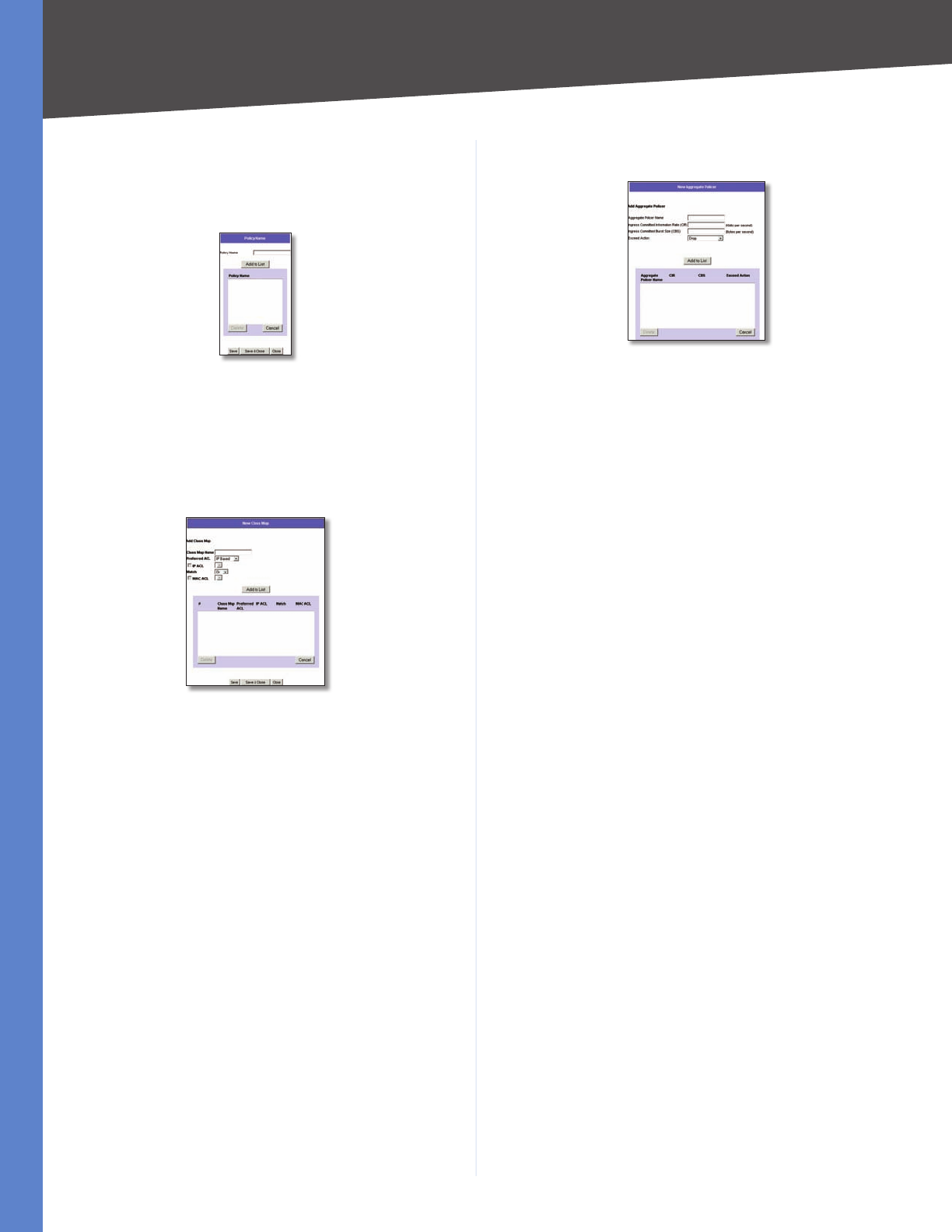
Chapter 5 Advanced Configuration
43
WebView Switches
Use the Policy Settings button to open the Policy Name
screen.
Advanced Mode > Policy Name
Advanced Mode > Policy Name
Policy Name Defines a new Policy name.
Add to List The Add to List button lets you add the policy
to the Policy Name table.
Advanced Mode > New Class Map
Advanced Mode > New Class Map
Class Map Name Defines a new Class Map name.
Preferred ACL Indicates if packets are first matched to
an IP-based ACL or a MAC based ACL. The possible field
values are:
IP Based ACLs •Matches packets to IP-based ACLs first,
then matches packets to MAC based ACLs.
MAC Based ACLs •Matches packets to MAC-based
ACLs first, then matches packets to IP-based ACLs.
IP ACL Matches packets to IP-based ACLs first, then
matches packets to MAC-based ACLs.
Match Criteria used to match IP addresses and/or MAC
addresses with an ACL’s address. The possible field values
are:
And •Both the MAC-based and the IP-based ACL must
match a packet.
Or •Either the MAC-based or the IP-based ACL must
match a packet.
MAC ACL Matches packets to MAC-based ACLs first, then
matches packets to IP-based ACLs.
Advanced Mode > New Aggregate Policer
Advanced Mode > New Aggregate Policer
Aggregate Policer Name Enter a name in this field.
Ingress Committed Information Rate (CIR) Defines the
CIR in bits per second. This field is only relevant when the
Police value is Single.
Ingress Committed Burst Size (CBS) Defines the CBS
in bytes per second. This field is only relevant when the
Police value is Single.
Exceed Action Action assigned to incoming packets
exceeding the CIR. This field is only relevant when the
Police value is Single. Possible values are:
Drop •Drops packets exceeding the defined CIR value.
Remark DSCP (Out of Profile DSCP) •Remarks packet’s
DSCP values exceeding the defined CIR value.
None •Forwards packets exceeding the defined CIR
value.
Spanning Tree
Spanning Tree Protocol (STP) provides tree topography for
any arrangement of bridges. STP also provides one path
between end stations on a network, eliminating loops.
Loops occur when alternate routes exist between hosts.
Loops in an extended network can cause bridges to
forward traffic indefinitely, resulting in increased traffic
and reducing network efficiency.
The device supports the following Spanning Tree
versions:
Classic STP •Provides a single path between end
stations, avoiding and eliminating loops.
Rapid STP •Detects and uses network topologies
that provide faster convergence of the spanning tree,
without creating forwarding loops.
Multiple STP •Provides full connectivity for packets
allocated to any VLAN. Multiple STP is based on the
RSTP. In addition, Multiple STP transmits packets
assigned to different VLANs through different MST
regions. MST regions act as a single bridge.
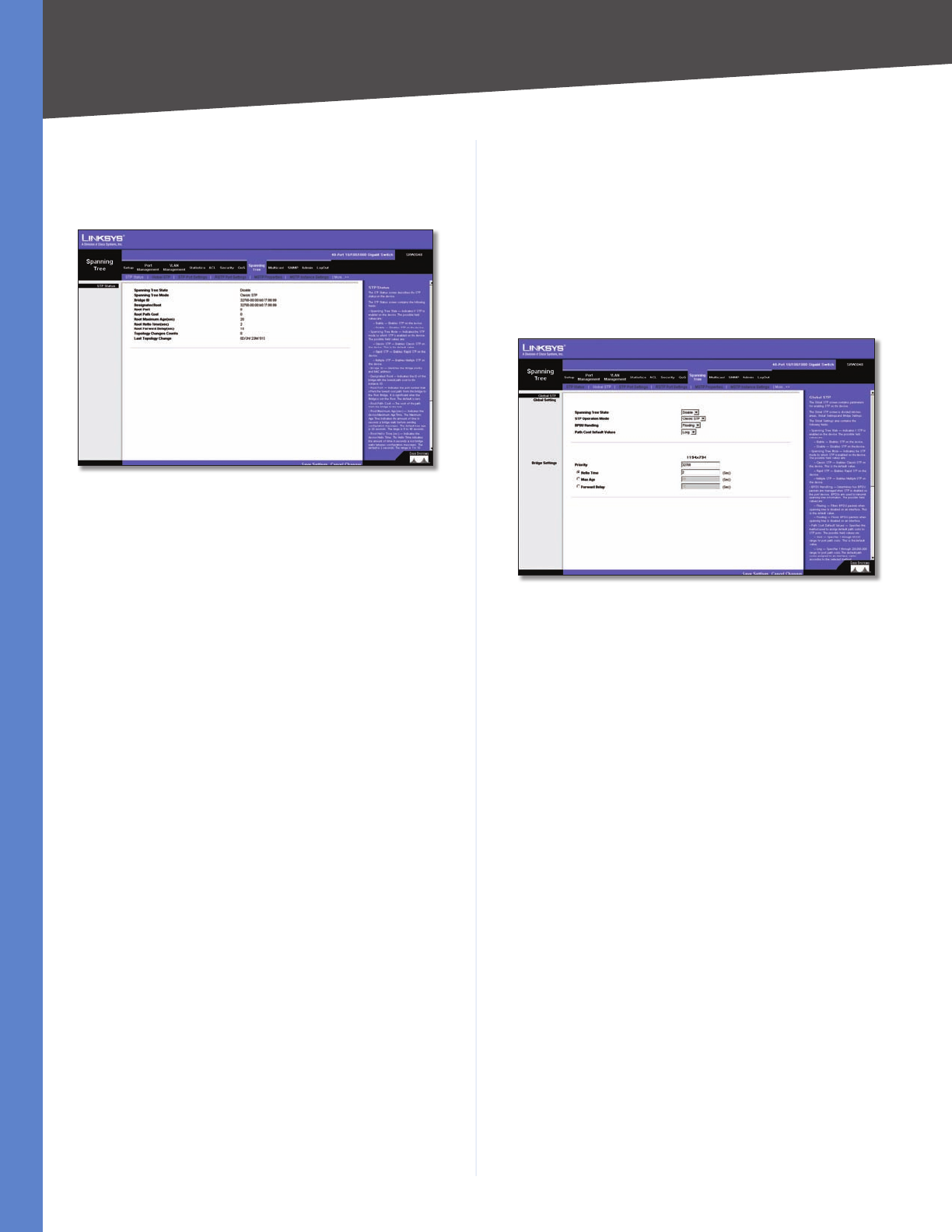
Chapter 5 Advanced Configuration
44
WebView Switches
Spanning Tree > STP Status
The STP Status screen describes the STP status on the
device.
Spanning Tree > STP Status
Spanning Tree State Indicates if STP is enabled on the
device.
Spanning Tree Mode Indicates the STP mode by which
STP is enabled on the device.
Bridge ID Identifies the Bridge priority and MAC
address.
Designated Root Indicates the ID of the bridge with the
lowest path cost to the instance ID.
Root Port Indicates the port number that offers the
lowest cost path from this bridge to the Root Bridge. It is
significant when the Bridge is not the Root. The default is
0.
Root Path Cost The cost of the path from this bridge to
the root.
Root Maximum Age (sec) Indicates the device
Maximum Age Time. The Maximum Age Time indicates
the amount of time in seconds a bridge waits before
sending configuration messages. The default max age is
20 seconds. The range is 6–40 seconds.
Root Hello Time (sec) Indicates the device Hello Time.
The Hello Time indicates the amount of time in seconds
a root bridge waits between configuration messages. The
default is 2 seconds. The range is 1–10 seconds.
Root Forward delay (sec) Indicates the device forward
delay time. The Forward Delay Time indicates the amount
of time in seconds a bridge remains in a listening and
learning state before forwarding packets. The default is
15 seconds. The range is 4–30 seconds.
Topology Changes Counts Indicates the total amount of
STP state changes that have occurred.
Last Topology Change Indicates the amount of time
that has elapsed since the bridge was initialized or reset,
and the last topographic change occurred. The time is
displayed in a day hour minute second format, for example,
2 days 5 hours 10 minutes and 4 seconds.
Spanning Tree > Global STP
The Global STP screen contains parameters for enabling
STP on the device.
Spanning Tree > Global STP
Global Setting
Spanning Tree State Indicates if STP is enabled on the
device.
STP Operation Mode Indicates the STP mode by which
STP is enabled on the device. The possible field values
are:
Classic STP •Enables Classic STP on the device. This is
the default value.
Rapid STP •Enables Rapid STP on the device.
Multiple STP •Enables Multiple STP on the device.
BPDU Handling Determines how BPDU packets are
managed when STP is disabled on the port/device. BPDUs
are used to transmit spanning tree information. The
possible field values are:
Filtering •Filters BPDU packets when spanning tree is
disabled on an interface. This is the default value.
Flooding •Floods BPDU packets when spanning tree is
disabled on an interface.
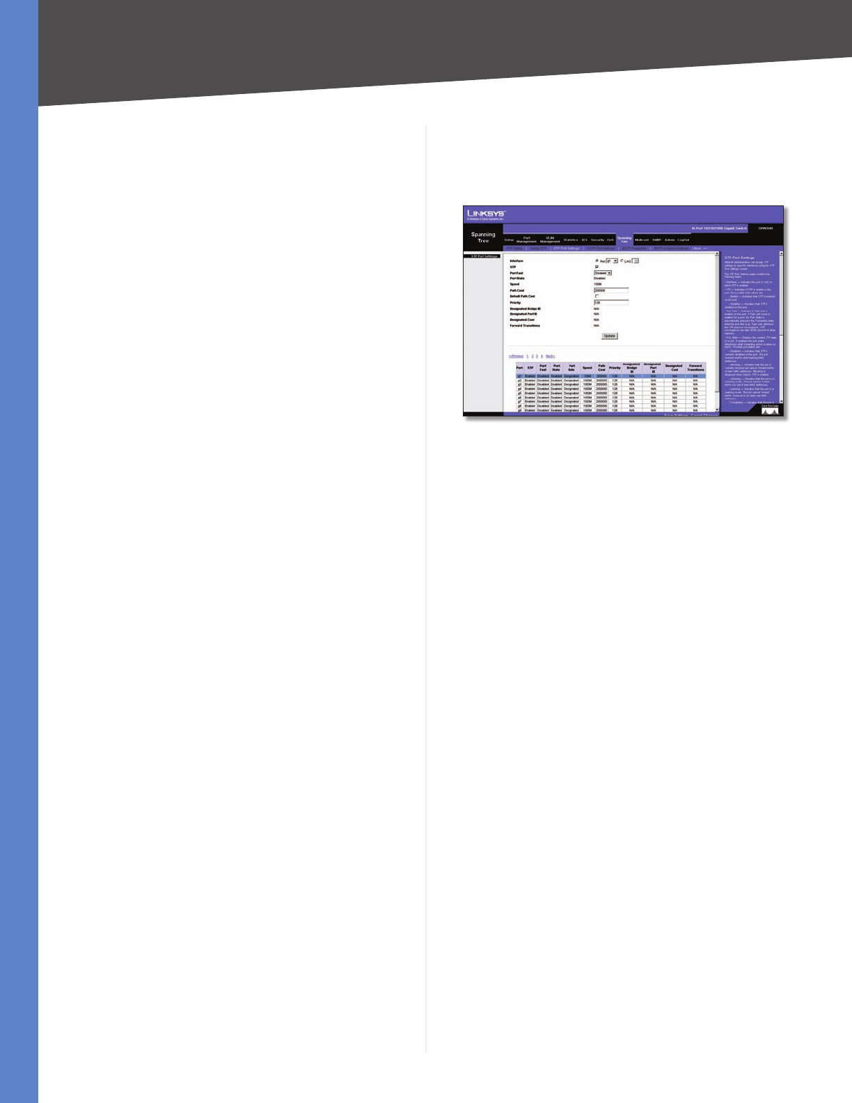
Chapter 5 Advanced Configuration
45
WebView Switches
Path Cost Default Values Specifies the method used to
assign default path costs to STP ports. The possible field
values are:
Short •Specifies a 1–65,535 range for port path costs.
This is the default value.
Long •Specifies a 1–200,000,000 range for port path
costs. The default path costs assigned to an interface
varies according to the selected method.
Bridge Settings
Priority Specifies the bridge priority value. When switches
or bridges are running STP, each is assigned a priority.
After exchanging BPDUs, the device with the lowest
priority value becomes the Root Bridge. The default value
is 32,768. The port priority value is provided in increments
of 4096. For example, 4096, 8192, 12,288, and so on. The
range is 0–65,535.
Hello Time Specifies the device Hello Time. The Hello
Time indicates the amount of time in seconds a root bridge
waits between configuration messages. The default is 2
seconds. The range is 1–10 seconds.
Max Age Specifies the device Maximum Age Time.
The Maximum Age Time indicates the amount of time
in seconds a bridge waits before sending configuration
messages. The default max age is 20 seconds. The range
is 6–40 seconds.
Forward Delay Specifies the device forward delay time.
The Forward Delay Time indicates the amount of time in
seconds a bridge remains in a listening and learning state
before forwarding packets. The default is 15 seconds. The
range is 4–30 seconds.
Spanning Tree > STP Port Settings
Network administrators can assign STP settings to specific
interfaces using the STP Interface Settings screen.
Spanning Tree > STP Port Settings
The STP Interface Settings page contains the following
fields:
Interface Indicates the port or LAG on which STP is
enabled.
STP Indicates if STP is enabled on the port.
Port Fast Indicates if Fast Link is enabled on the port.
If Fast Link mode is enabled for a port, the Port State
is automatically placed in the Forwarding state when
the port link is up. Fast Link optimizes the STP protocol
convergence. STP convergence can take 30–60 seconds
in large networks.
Port State Displays the current STP state of a port. If
enabled, the port state determines what forwarding
action is taken on traffic. Possible port states are:
Disabled •Indicates that STP is currently disabled on
the port. The port forwards traffic while learning MAC
addresses.
Blocking •Indicates that the port is currently blocked
and cannot forward traffic or learn MAC addresses.
Blocking is displayed when Classic STP is enabled.
Listening •Indicates that the port is in Listening mode.
The port cannot forward traffic nor can it learn MAC
addresses.
Learning •Indicates that the port is in Learning mode.
The port cannot forward traffic, however it can learn
new MAC addresses.
Forwarding •Indicates that the port is in Forwarding
mode. The port can forward traffic and learn new MAC
addresses.
Speed Indicates the speed at which the port is
operating.
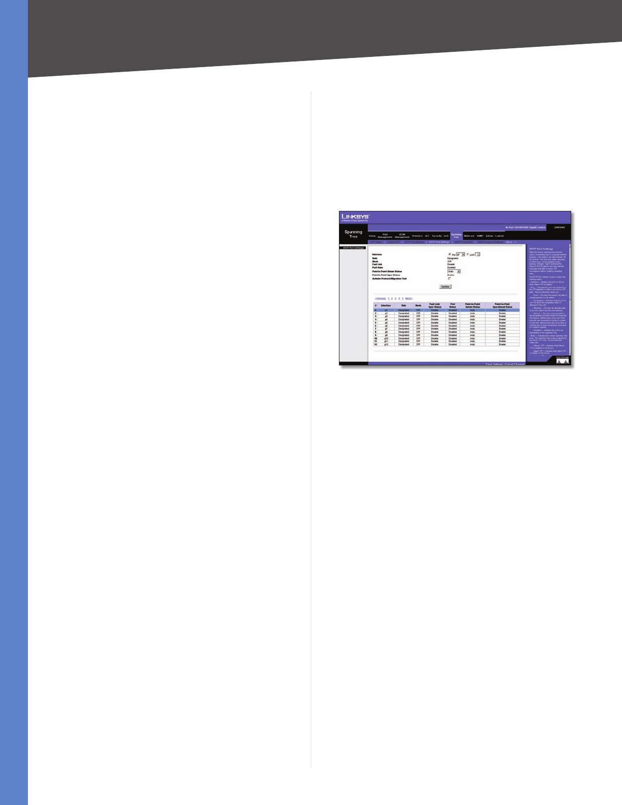
Chapter 5 Advanced Configuration
46
WebView Switches
Path Cost Indicates the port contribution to the root
path cost. The path cost is adjusted to a higher or lower
value, and is used to forward traffic when a path being
rerouted.
Default Path Cost When selected the default path cost
is implemented.
Priority Priority value of the port. The priority value
influences the port choice when a bridge has two ports
connected in a loop. The priority value is between 0–240.
The priority value is provided in increments of 16.
Designated Bridge ID Indicates the bridge priority and
the MAC Address of the designated bridge.
Designated Port ID Indicates the selected port’s priority
and interface.
Designated Cost Indicates the cost of the port
participating in the STP topology. Ports with a lower cost
are less likely to be blocked if STP detects loops.
Forward Transitions Indicates the number of times the
port has changed from the Blocking state to Forwarding
state.
Spanning Tree > RSTP Port Settings
While the classic spanning tree prevents Layer 2 forwarding
loops in a general network topology, convergence can take
between 30–60 seconds. This time may delay detecting
possible loops, and propagating status topology changes.
Rapid Spanning Tree Protocol (RSTP) detects and uses
network topologies that allow a faster STP convergence
without creating forwarding loops.
Spanning Tree > RSTP Port Settings
Interface Displays the port or LAG on which Rapid STP
is enabled.
Role Indicates the port role assigned by the STP algorithm
in order to provide to STP paths. The possible field values
are:
Root •Provides the lowest cost path to forward packets
to root switch.
Designated •Indicates that the port or LAG via which
the designated switch is attached to the LAN.
Alternate •Provides an alternate path to the root
switch from the root interface.
Backup •Provides a backup path to the designated
port path toward the Spanning Tree leaves. Backup
ports occur only when two ports are connected in a
loop by a point-to-point link. Backup ports also occur
when a LAN has two or more connections connected
to a shared segment.
Disabled •Indicates the port is not participating in the
Spanning Tree.
Mode Indicates the current Spanning Tree mode. The
Spanning Tree mode is selected in the Global STP screen.
The possible field values are:
Classic STP •Indicates that Classic STP is enabled on
the device.
Rapid STP •Indicates that Rapid STP is enabled on the
device.
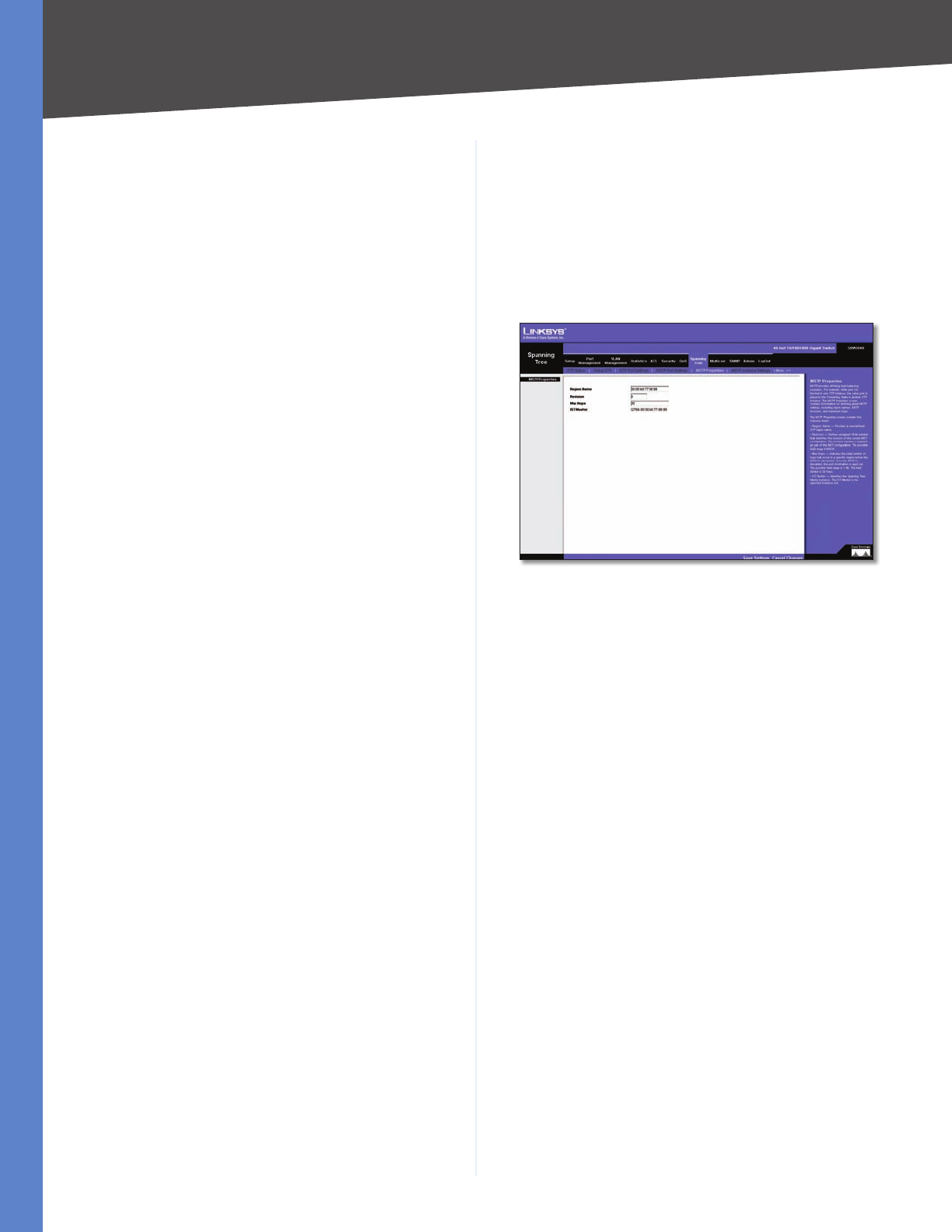
Chapter 5 Advanced Configuration
47
WebView Switches
Multiple STP •Indicates that Multiple STP is enabled
on the device.
Fast Link Indicates if Fast Link is enabled or disabled for
the port or LAG. If Fast Link is enabled for a port, the port is
automatically placed in the forwarding state (configurable
from Spanning Tree > STP Port Settings).
Port State Indicates if RSTP is enabled on the interface.
Point-to-Point Admin Status Indicates if a point-to-point
links are established, or permits the device to establish a
point-to-point link. The possible field values are:
Auto •Enables automatic establishment of point-to-
point links.
Enabled •Enables the device to establish a point-to-
point link. To establish communications over a point-
to-point link, the originating PPP first sends Link
Control Protocol (LCP) packets to configure and test
the data link. After a link is established and optional
facilities are negotiated as needed by the LCP, the
originating PPP sends Network Control Protocols (NCP)
packets to select and configure one or more network
layer protocols. When each of the chosen network
layer protocols has been configured, packets from
each network layer protocol can be sent over the link.
The link remains configured for communications until
explicit LCP or NCP packets close the link, or until some
external event occurs. This is the actual switch port link
type. It may differ from the administrative state.
Disabled •Disables point-to-point link.
Point-to-Point Oper Status Indicates the Point-to-Point
operating state.
Activate Protocol Migration Test This option sends
Link Control Protocol (LCP) packets to test if a data link is
enabled.
Spanning Tree > MSTP Properties
Multiple Spanning Tree Protocol (MSTP) provides differing
load balancing scenarios. For example, while port A is
blocked in one STP instance, the same port is placed in
the Forwarding State in another STP instance. The MSTP
Properties screen contains information for defining global
MSTP settings, including region names, MSTP revisions,
and maximum hops.
Spanning Tree > MSTP Properties
The MSTP Properties screen contains the following fields:
Region Name Provides a user-defined STP region name.
Revision Defines unsigned 16-bit number that identifies
the revision of the current MST configuration. The revision
number is required as part of the MST configuration. The
possible field range 0–65,535.
Max Hops Indicates the total number of hops that occur
in a specific region before the BPDU is discarded. Once the
BPDU is discarded, the port information is aged out. The
possible field range is 1–40. The field default is 20 hops.
IST Master Identifies the Spanning Tree Master instance.
The IST Master is the specified instance root.
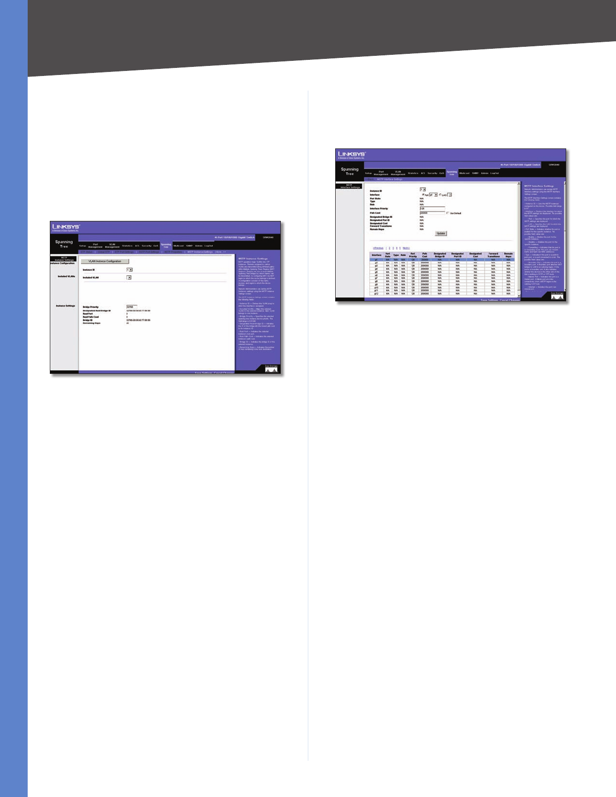
Chapter 5 Advanced Configuration
48
WebView Switches
Spanning Tree > MSTP Instance Settings
MSTP operation maps VLANs into STP instances. Packets
assigned to various VLANs are transmitted along different
paths within Multiple Spanning Trees Regions (MST
Regions). Regions are one or more Multiple Spanning
Tree bridges by which frames can be transmitted. In
configuring MST, the MST region to which the device
belongs is defined. A configuration consists of the name,
revision, and region to which the device belongs.
Spanning Tree > MSTP Instance Settings
Network Administrators can define MSTP Instances
settings using the MSTP Instance Settings screen.
Instance ID Defines the VLAN group to which the
interface is assigned.
Included VLAN Maps the selected VLAN to the selected
instance. Each VLAN belongs to one instance.
Bridge Priority Specifies the selected spanning tree
instance device priority. The field range is 0–61,440.
Designated Root Bridge ID Indicates the ID of the bridge
with the lowest path cost to the instance ID.
Root Port Indicates the selected instance’s root port.
Root Path Cost Indicates the selected instance’s path
cost.
Bridge ID Indicates the bridge ID of the selected
instance.
Remaining Hops Indicates the number of hops remaining
to the next destination.
Spanning Tree > MSTP Interface Settings
Network Administrators can assign MSTP Interface settings
using the MSTP Interface Settings screen.
Spanning Tree > MSTP Interface Settings
The MSTP Interface Settings screen contains the following
fields:
Instance ID Lists the MSTP instances configured on the
device. Possible field range is 0–15.
Interface Displays the interface for which the MSTP
settings are displayed. The possible field values are:
Port •Specifies the port for which the MSTP settings
are displayed.
LAG •Specifies the LAG for which the MSTP settings
are displayed.
Port State Indicates whether the port is enabled for the
specific instance.
Type Indicates if the port is a point-to-point port, or a
port connected to a hub. The possible field values are:
Boundary Port •Indicates the port is a boundary port.
A Boundary port attaches MST bridges to LAN in an
outlying region. If the port is a boundary port, it also
indicates whether the device on the other side of the
link is working in RSTP or STP mode.
Master Port •Indicates the port is a master port. A
Master port provides connectivity from a MSTP region
to the outlying CIST root.
Internal •Indicates the port is an internal port.
Role Indicates the port role assigned by the STP algorithm
in order to provide to STP paths. The possible field values
are:
Root •Provides the lowest cost path to forward packets
to root device.
Designated •Indicates the port or LAG via which the
designated device is attached to the LAN.
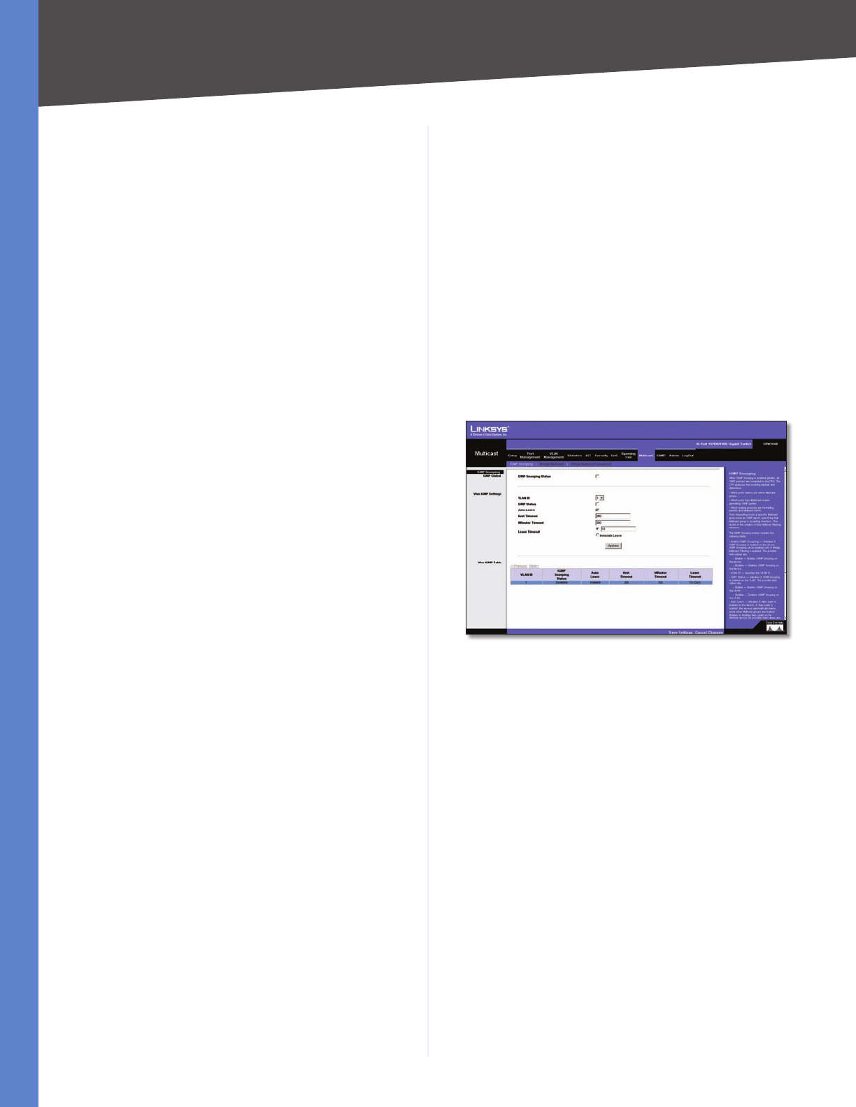
Chapter 5 Advanced Configuration
49
WebView Switches
Alternate •Provides an alternate path to the root
device from the root interface.
Backup •Provides a backup path to the designated
port path toward the Spanning Tree leaves. Backup
ports occur only when two ports are connected in a
loop by a point-to-point link. Backup ports also occur
when a LAN has two or more connections connected
to a shared segment.
Disabled •Indicates the port is not participating in the
Spanning Tree.
Interface Priority Defines the interface priority for
specified instance. The default value is 128.
Path Cost Indicates the port contribution to the
Spanning Tree instance. The range should always be
1–200,000,000.
Designated Bridge ID Indicates that the bridge ID
number that connects the link or shared LAN to the root.
Designated Port ID Indicates that the Port ID number on
the designated bridge that connects the link or the shared
LAN to the root.
Designated Cost Indicates that the default path cost
is assigned according to the method selected on the
Spanning Tree Global Settings screen.
Forward Transitions Indicates the number of times the
port has changed from Forwarding state to Blocking
state.
Remaining Hops Indicates the hops remaining to the
next destination.
Multicast > IGMP Snooping
When Internet Group Management Protocol (IGMP)
Snooping is enabled globally, all IGMP packets are
forwarded to the CPU. The CPU analyzes the incoming
packets and determines:
Which ports want to join which Multicast groups? •
Which ports have Multicast routers generating IGMP •
queries?
Which routing protocols are forwarding packets and •
Multicast traffic?
Ports requesting to join a specific Multicast group issue an
IGMP report, specifying that Multicast group is accepting
members. This results in the creation of the Multicast
filtering database.
Multicast > IGMP Snooping
IGMP Snooping Status Indicates if IGMP Snooping is
enabled on the device. IGMP Snooping can be enabled
only if Bridge Multicast Filtering is enabled.
VLAN ID Specifies the VLAN ID.
IGMP Status Indicates if IGMP snooping is enabled on
the VLAN.
Auto Learn Indicates if Auto Learn is enabled on the
device. If Auto Learn is enabled, the device automatically
learns where other Multicast groups are located. Enables
or disables Auto Learn on the Ethernet device.
Host Timeout Indicates the amount of time the host
waits to receive a message before timing out. The default
time is 260 seconds.
MRouter Timeout Indicates the amount of the time the
Multicast router waits to receive a message before it times
out. The default value is 300 seconds.
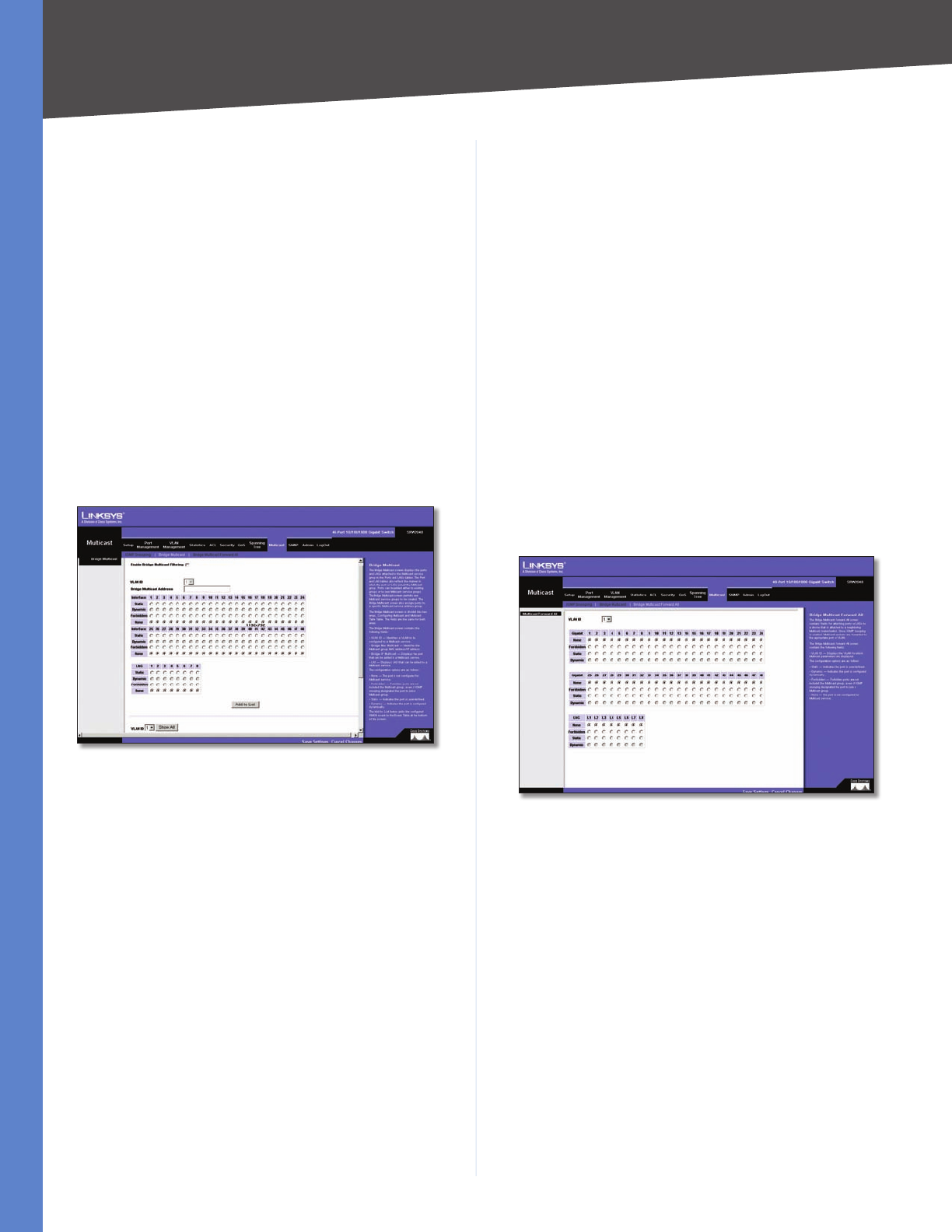
Chapter 5 Advanced Configuration
50
WebView Switches
Leave Timeout Indicates the amount of time the host
waits, after requesting to leave the IGMP group and not
receiving a Join message from another station, before
timing out. If a Leave Timeout occurs, the switch notifies
the Multicast device to stop sending traffic The Leave
Timeout value is either user-defined, or an immediate
leave value. The default timeout is 10 seconds.
Multicast > Bridge Multicast
The Bridge Multicast screen displays the ports and LAGs
attached to the Multicast service group in the Ports and
LAGs tables. The Port and LAG tables also reflect the
manner in which the port or LAGs joined the Multicast
group. Ports can be added either to existing groups or to
new Multicast service groups. The Bridge Multicast screen
permits new Multicast service groups to be created. The
Bridge Multicast screen also assigns ports to a specific
Multicast service address group.
Multicast > Bridge Multicast
The Bridge Multicast screen is divided into two areas,
Configuring Multicast and Multicast Table. The fields are
the same for both areas.
Enable Bridge Multicast Filtering Enables Bridge
Multicast Filtering.
VLAN ID Identifies a VLAN to be configured to a Multicast
service.
Bridge Multicast Address Identifies the Multicast group
MAC address/IP address.
Bridge IP Multicast Displays the port that can be added
to a Multicast service.
Interface or LAG Displays LAG that can be added to a
Multicast service.
The configuration options are as follows:
Static •The port is user-defined.
Dynamic •The port is configured dynamically.
Forbidden •Forbidden ports are not included the
Multicast group, even if IGMP snooping designated
the port to join a Multicast group.
None •The port is not configured for Multicast service.
Use the Add to List button to add the configured RMON
event to the Event Table at the bottom of the screen.
Multicast > Bridge Multicast Forward All
The Bridge Multicast Forward All screen contains fields
for attaching ports or LAGs to a device that is attached
to a neighboring Multicast router/switch. Once IGMP
Snooping is enabled, Multicast packets are forwarded to
the appropriate port or VLAN.
Multicast > Bridge Multicast Forward All
The Bridge Multicast Forward All screen contains the
following fields:
VLAN ID Displays the VLAN for which Multicast
parameters are displayed.
The configuration options are as follows:
None •The port is not configured for Multicast service.
Forbidden •Forbidden ports are not included the
Multicast group, even if IGMP snooping designated
the port to join a Multicast group.
Static •The port is user-defined.
Dynamic •The port is configured dynamically.
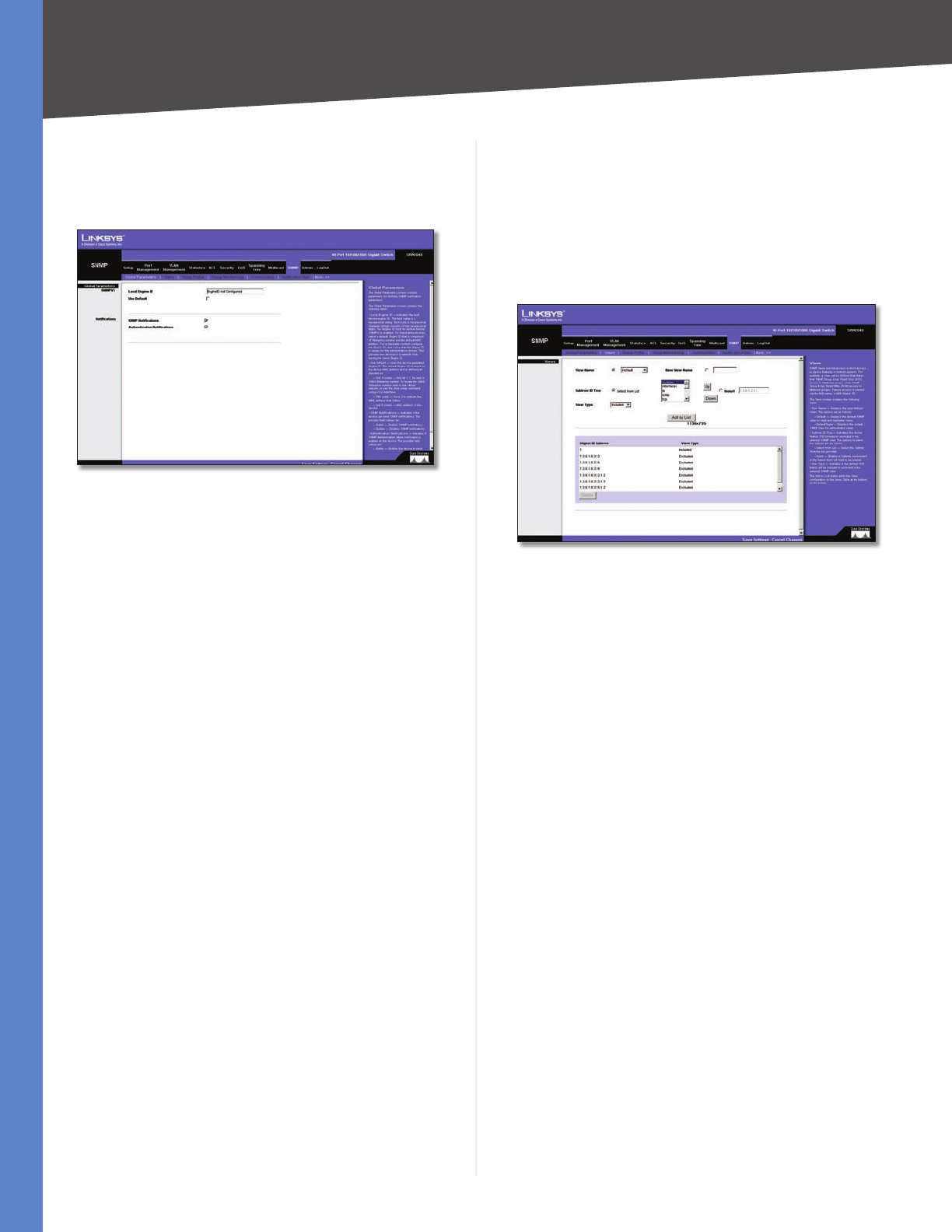
Chapter 5 Advanced Configuration
51
WebView Switches
SNMP > Global Parameters
The Global Parameters screen contains parameters for
defining SNMP notification parameters.
SNMP > Global Parameters
Local Engine ID Indicates the local device engine ID. The
field value is a hexadecimal string. Each byte in hexadecimal
character strings consists of two hexadecimal digits. Each
byte can be separated by a period or a colon. The Engine
ID must be defined before SNMPv3 is enabled. For stand-
alone devices, select a default Engine ID that is comprised
of Enterprise number and the default MAC address. For a
stackable system configure the Engine ID, and verify that
the Engine ID is unique for the administrative domain.
This prevents two devices in a network from having the
same Engine ID.
Use Default Uses the device generated Engine ID. The
default Engine ID is based on the device MAC address and
is defined per standard as:
First 4 octets—first bit = 1, the rest is IANA Enterprise •
number.
Fifth octet—Set to •3 to indicate the MAC address that
follows.
Last 6 octets—MAC address of the device. •
SNMP Notifications Indicates if the device can send
SNMP notifications.
Authentication Notifications Indicates if SNMP
Authentication failure notification is enabled on the
device.
SNMP > Views
SNMP Views provide access or block access to device
features or feature aspects. For example, a view can be
defined that states that SNMP Group A has Read Only
(R/O) access to Multicast groups, while SNMP Group B
has Read-Write (R/W) access to Multicast groups. Feature
access is granted via the MIB name, or MIB Object ID.
SNMP > Views
View Name Displays the user-defined views. The options
are as follows:
Default •Displays the default SNMP view for read and
read/write views.
DefaultSuper •Displays the default SNMP view for
administrator views.
Subtree ID Tree Indicates the device feature OID included
or excluded in the selected SNMP view. The options to
select the Subtree are as follows:
Select from List •Select the Subtree from the list
provided.
Insert •Enables a Subtree not included in the Select
from List field to be entered.
View Type Indicates if the defined OID branch will be
included or excluded in the selected SNMP view.
Use the Add to List button to add the Views configuration
to the Views Table at the bottom of the screen.
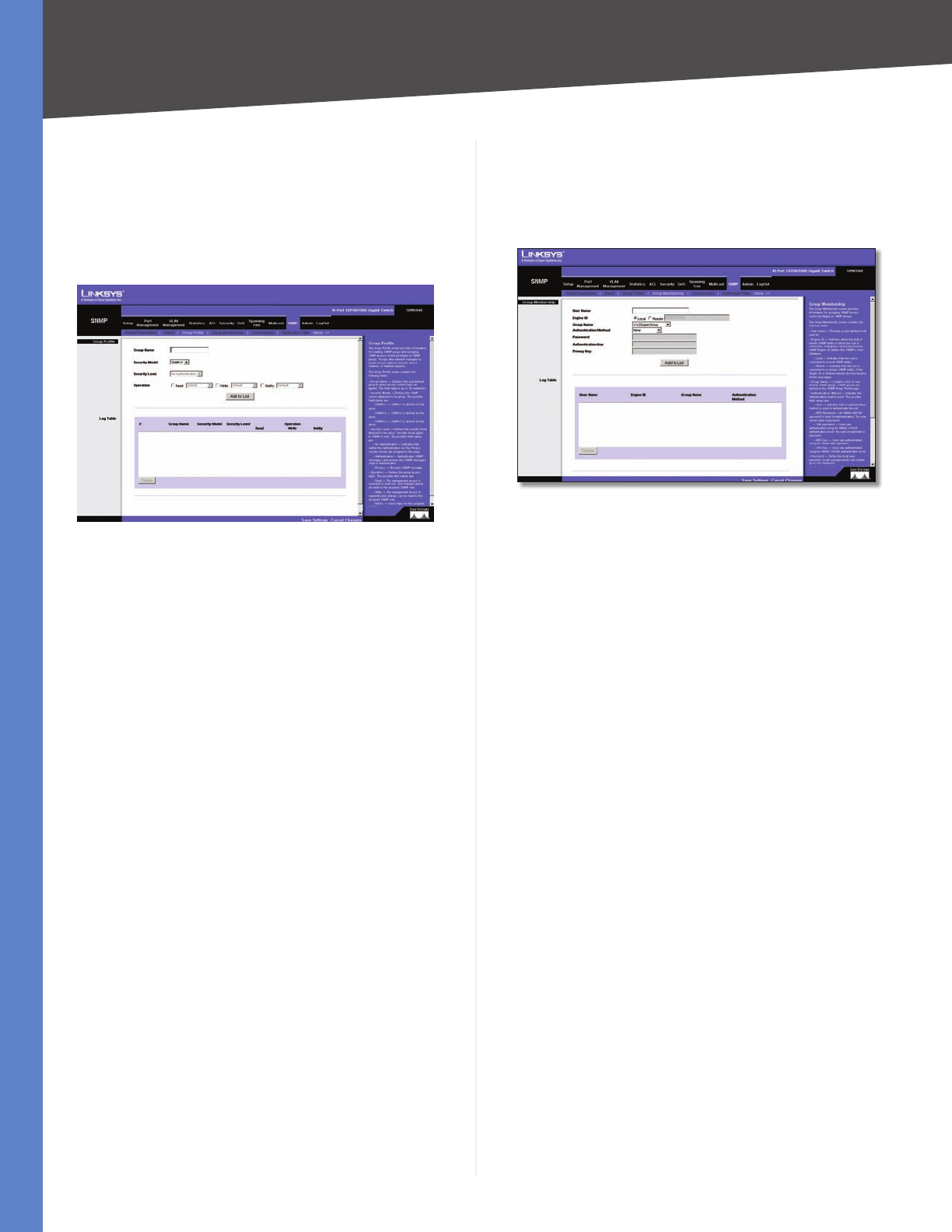
Chapter 5 Advanced Configuration
52
WebView Switches
SNMP > Group Profile
The Group Profile screen provides information for creating
SNMP groups and assigning SNMP access control privileges
to SNMP groups. Groups allow network managers to
assign access rights to specific device features, or features
aspects.
SNMP > Group Profile
Group Name Displays the user-defined group name
(up to 30 characters) to which access control rules are
applied.
Security Model Defines the SNMP version attached to
the group. The possible field values are:
SNMPv1 •SNMPv1 is defined for the group.
SNMPv2 •SNMPv2 is defined for the group.
SNMPv3 •SNMPv3 is defined for the group.
Security Level Defines the security level attached to the
group. Security levels apply to SNMPv3 only. The possible
field values are:
No Authentication •Indicates that neither the
Authentication nor the Privacy security levels are
assigned to the group.
Authentication •Authenticates SNMP messages, and
ensures the SNMP messages origin is authenticated.
Privacy •Encrypts SNMP messages.
Operation Defines the group access rights. The possible
field values are:
Read •The management access is restricted to read-
only, and changes cannot be made to the assigned
SNMP view.
Write •The management access is read-write and
changes can be made to the assigned SNMP view.
Notify •Sends traps for the assigned SNMP view.
SNMP > Group Membership
The Group Membership screen provides information
for assigning SNMP access control privileges to SNMP
groups.
SNMP > Group Membership
User name Provides a user-defined local user list.
Engine ID Indicates either the local or remote SNMP entity
to which the user is connected. Changing or removing the
local SNMP Engine ID deletes the SNMPv3 User Database.
Local •Indicates that the user is connected to a local
SNMP entity.
Remote •Indicates that the user is connected to a
remote SNMP entity. If the Engine ID is defined, remote
devices receive inform messages.
Group Name Contains a list of user-defined SNMP
groups. SNMP groups are defined in the SNMP Group
Profile page.
Authentication Method Indicates the Authentication
method used. The possible field values are:
None •Indicates that no authentication method is
used to authenticate the port.
MD5 Password •Indicates that port authentication
is performed via HMAC-MD5-96 password
authentication.
SHA Password •Indicates that port authentication
is performed via HMAC-SHA-96 password
authentication.
MD5 Key •Indicates that port authentication is
performed via the HMAC-MD5 algorithm.
SHA Key •Indicates that port authentication is
performed via HMAC-SHA-96 authentication.
Password Define the local user password. Local user
passwords can contain up to 159 characters.
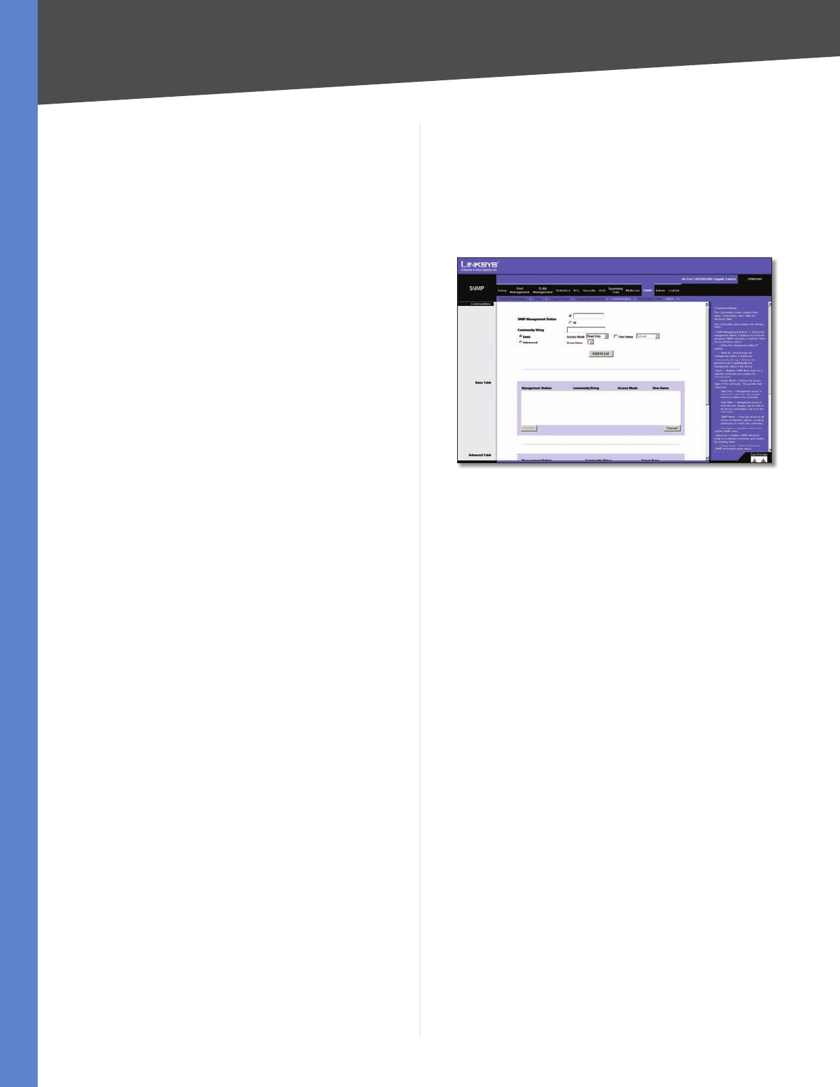
Chapter 5 Advanced Configuration
53
WebView Switches
Authentication Key Defines the HMAC-MD5-96 or
HMAC-SHA-96 authentication level. The authentication
and privacy keys are entered to define the authentication
key. If only authentication is required, 16 bytes are defined.
If both privacy and authentication are required, 32 bytes
are defined. Each byte in hexadecimal character strings is
two hexadecimal digits. Each byte can be separated by a
period or a colon.
Privacy Key Defines the Privacy Key (LSB). If only
authentication is required, 20 bytes are defined. If both
privacy and authentication are required, 36 bytes are
defined. Each byte in hexadecimal character strings is
two hexadecimal digits. Each byte can be separated by a
period or colon.
Use the Add to List button to add the Group Membership
configuration to the respective table at the bottom of the
screen.
SNMP > Communities
The Communities screen contains three areas:
Communities •
Basic Table •
Advanced Table •
SNMP > Communities
SNMP Management Station Defines the management
station IP address for which the advanced SNMP
community is defined. There are two definition options:
Define the management station IP address. •
All •Includes all management station IP addresses.
Community String Defines the password used to
authenticate the management station to the device.
Basic Enables SNMP Basic mode for a selected community
and contains the following fields:
Access Mode Defines the access rights of the community.
The possible field values are:
Read Only •Management access is restricted to read-
only, and changes cannot be made to the community.
Read Write •Management access is read-write and
changes can be made to the device configuration, but
not to the community.
SNMP Admin •User has access to all device
configuration options, as well as permissions to modify
the community.
View Name Contains a list of user-defined SNMP views.
Advanced Enables SNMP Advanced mode for a selected
community and contains the following fields:
Group Name Defines advanced SNMP communities
group names.
Use the Add to List button to add the Communities
configuration to the respective Table at the bottom of the
screen.
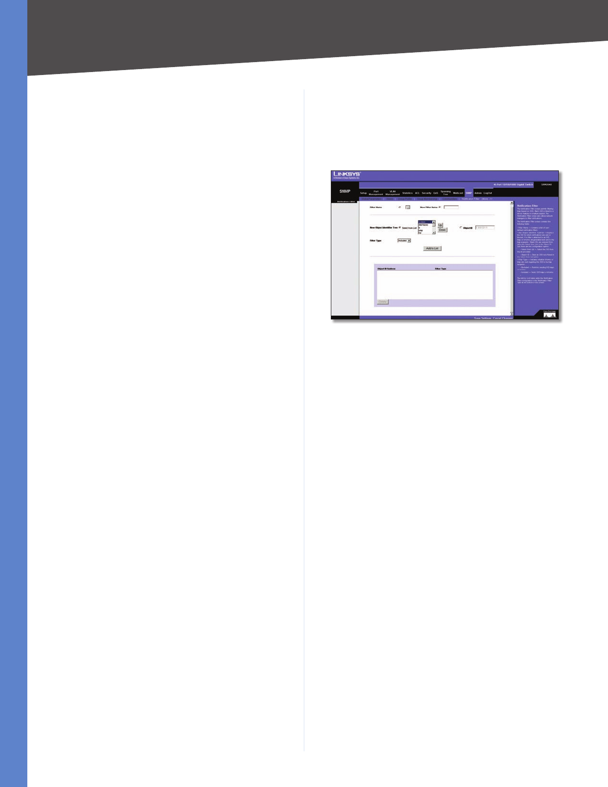
Chapter 5 Advanced Configuration
54
WebView Switches
Base Table
Management Station Displays the management station
IP address for which the basic SNMP community is
defined.
Community String Displays the password used to
authenticate the management station to the device.
Access Mode Displays the access rights of the
community.
View Name Displays the user-defined SNMP view.
Advanced Table
Management Station Displays the management station
IP address for which the basic SNMP community is
defined.
Community String Displays the password used to
authenticate the management station to the device.
Group Name Displays advanced SNMP communities
group name.
SNMP > Notification Filter
The Notification Filter screen permits filtering traps based
on OIDs (Object Identifiers). Each OID is linked to a device
feature or a feature aspect. The Notification Filter screen
also allows network managers to filter notifications.
SNMP > Notification Filter
Filter Name Contains a list of user-defined notification
filters.
New Object Identifier Subtree Displays the OID for
which notifications are sent or blocked. If a filter is
attached to an OID, traps or informs are generated and
sent to the trap recipients. Object IDs are selected from
either the Select from List or the Object ID List. There are
two configuration options:
Select from List Select the OID from the list provided.
Object ID Enter an OID not offered in the Select from List
option.
Filter Type Indicates whether informs or traps are sent
regarding the OID to the trap recipients.
Excluded •Restricts sending OID traps or informs.
Included •Sends OID traps or informs.
Use the Add to List button to add the Notification Filter
configuration to the Notification Filter Table at the bottom
of the screen.
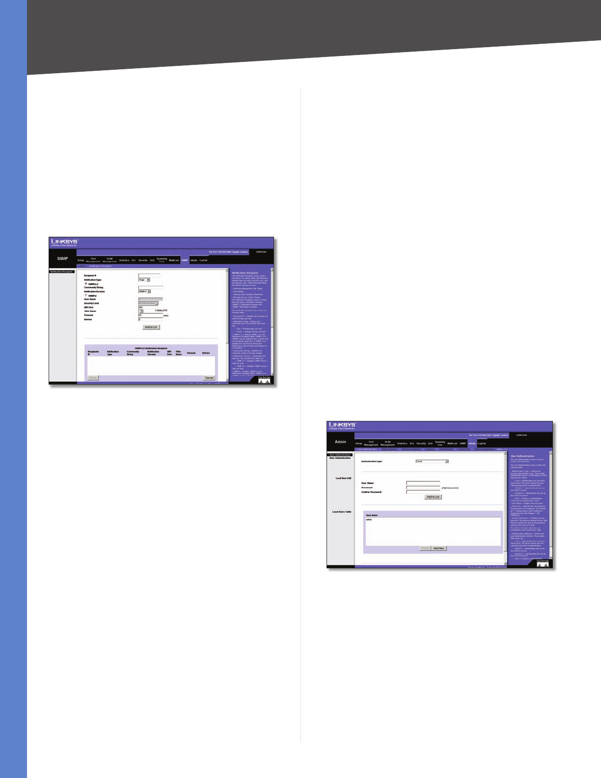
Chapter 5 Advanced Configuration
55
WebView Switches
SNMP > Notification Recipient
The Notification Recipient screen contains information for
defining filters that determine whether traps are sent to
specific users, and the trap type sent. SNMP notification
filters provide the following services:
Identifying Management Trap Targets •
Trap Filtering •
Selecting Trap Generation Parameters •
Providing Access Control Checks •
SNMP > Notification Recipient
Recipient IP Indicates the IP address to whom the traps
are sent.
Notification Type Defines the notification sent. The
possible field values are:
Traps •Indicates traps are sent.
Informs •Indicates informs are sent.
SNMPv1,2 Enables SNMPv1,2 as the Notification
Recipient. Either SNMPv1,2 or SNMPv3 can be enabled at
any one time, but not both at the same time. If SNMPv1,2
is enabled, the Community String and Notification Version
fields are enabled for configuration:
Community String •Identifies the community string
of the trap manager.
Notification Version •Determines the trap type. The
possible field values are:
SNMP V1 •Indicates SNMP Version 1 traps are sent.
SNMP V2 •Indicates SNMP Version 2 traps are sent.
SNMPv3 Enables SNMPv3 as the Notification Recipient.
Either SNMPv1,2 or SNMPv3 can be enabled at any one
time, but not both at the same time. If SNMPv3is enabled,
the User Name and Security Level fields are enabled for
configuration:
User Name Defines the user to whom SNMP notifications
are sent.
Security Level Defines the means by which the packet is
authenticated. The possible field values are:
No Authentication •The packet is neither
authenticated nor encrypted.
Authentication •The packet is authenticated.
Privacy •Indicates the packet is both authenticated
and encrypted.
UDP Port Displays the UDP port used to send notifications.
The default is 162.
Filter Name Indicates if the SNMP filter for which the
SNMP Notification filter is defined.
Timeout Indicates the amount of time (seconds) the
device waits before resending informs. The default is 15
seconds.
Retries Indicates the amount of times the device resends
an inform request. The default is 3 seconds.
Use the Add to List button to add the Notification
Recipient configuration to the relevant table at the bottom
of the screen.
Admin > User Authentication
You can modify user passwords in the User Authentication
screen.
Admin > User Authentication
Authentication Type Defines the user authentication
methods. Combinations of all the authentication methods
can be selected. The possible field values are:
Local •Authenticates the user at the device level.
The device checks the user name and password for
authentication.
RADIUS •Authenticates the user at the RADIUS server.
TACACS+ •Authenticates the user at the TACACS+
server.
None •Assigns no authentication method to the
authentication profile.
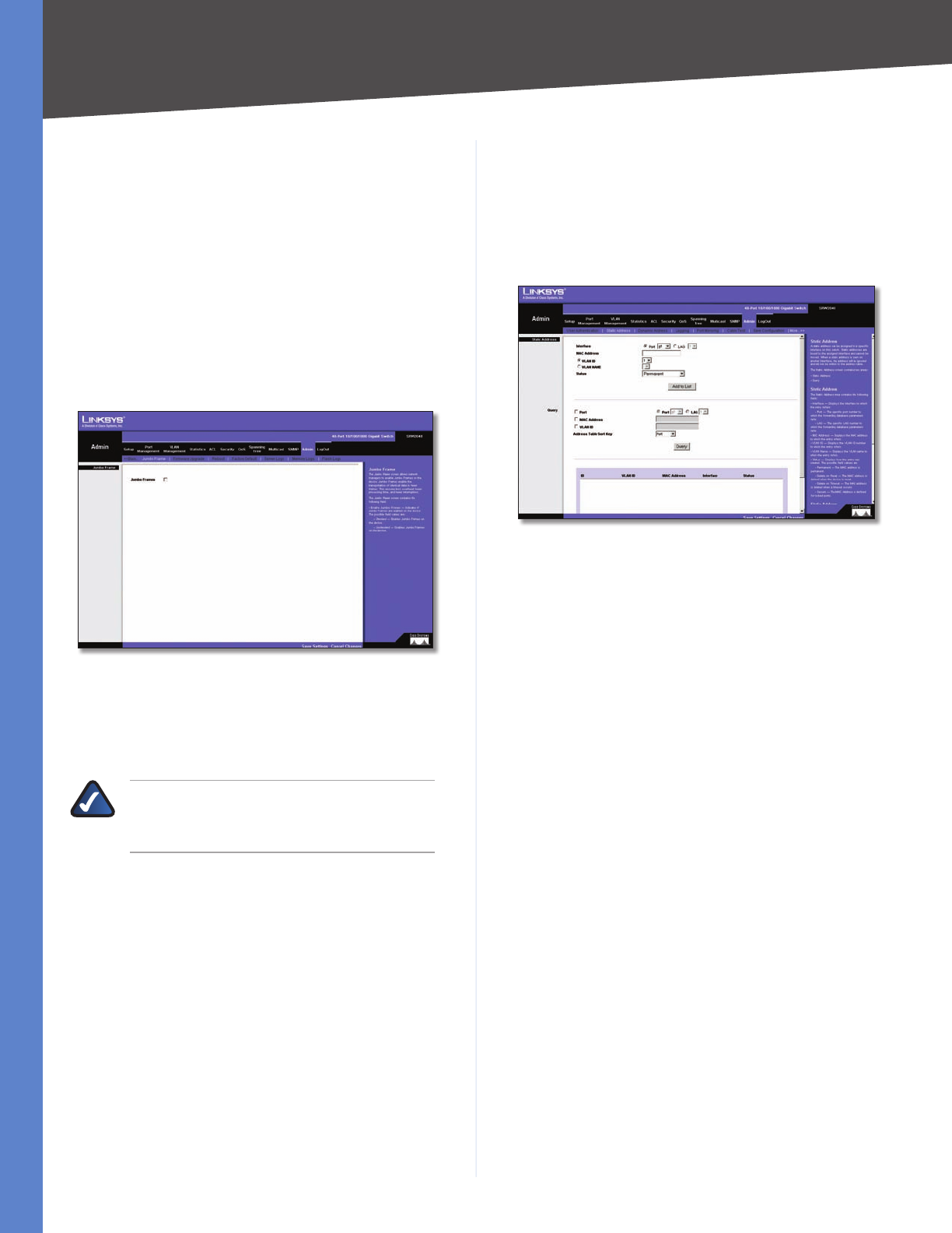
Chapter 5 Advanced Configuration
56
WebView Switches
User Name Displays the user name.
Password Specifies the new password. The password is
not displayed. As it entered an “*” corresponding to each
character is displayed in the field. The range is 1–159
characters.
Confirm Password Confirms the new password. The
password entered into this field must be exactly the same
as the password entered in the Password field.
Use the Add to List button to add the user configuration
to the Local User’s Table.
Admin > Jumbo Frames
Admin > Jumbo Frames
Jumbo Frames This option enables the transportation of
identical data in fewer frames. This ensures less overhead,
lower processing time and fewer interruptions.
NOTE: The Jumbo Frames tab is not an available
option on the SRW224G4 and SRW248G4
Switches.
Admin > Static Address
A static address can be assigned to a specific interface on
this switch. Static addresses are bound to the assigned
interface and cannot be moved. When a static address is
seen on another interface, the address will be ignored and
will not be written to the address table.
Admin > Static Address
Interface Displays the interface to which the entry
refers:
Port •The specific port number to which the forwarding
database parameters refer.
LAG •The specific LAG number to which the forwarding
database parameters refer.
MAC Address Displays the MAC address to which the
entry refers.
VLAN ID Displays the VLAN ID number to which the entry
refers.
VLAN Name Displays the VLAN name to which the entry
refers.
Status Displays how the entry was created. The possible
field values are:
Permanent •The MAC address is permanent.
Delete on Reset •The MAC address is deleted when
the device is reset.
Delete on Timeout •The MAC address is deleted when
a timeout occurs.
Secure •The MAC Address is defined for locked ports.
Query
Port Specifies the interface for which the table is queried.
There are two interface types from which to select.
Port •The specific port number.
LAG •The specific LAG number.
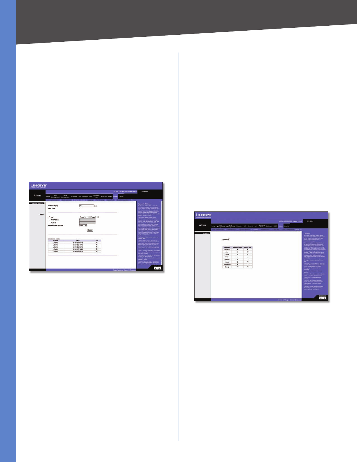
Chapter 5 Advanced Configuration
57
WebView Switches
MAC Address Specifies the MAC address for which the
table is queried.
VLAN ID Specifies the VLAN ID for which the table is
queried.
Address Table Sort Key Specifies the means by which
the Dynamic MAC Address Table is sorted. The address
table can be sorted by address, VLAN, or interface.
Admin > Dynamic Address
The Dynamic Address Table contains the MAC addresses
learned by monitoring the source address for traffic
entering the switch. When the destination address for
inbound traffic is found in the database, the packets
intended for that address are forwarded directly to the
associated port. Otherwise, the traffic is flooded to all
ports.
Admin > Dynamic Address
The Dynamic Address screen contains parameters for
querying information in the Dynamic MAC Address Table,
including the interface type, MAC addresses, VLAN, and
table storing. The Dynamic MAC Address table contains
information about the aging time before a dynamic MAC
address is erased, and includes parameters for querying
and viewing the Dynamic MAC Address table. The Dynamic
MAC Address table contains address parameters by which
packets are directly forwarded to the ports. The Dynamic
Address Table can be sorted by interface, VLAN, and MAC
Address.
Address Aging Specifies the amount of time (in seconds)
the MAC address remains in the Dynamic MAC Address
table before it times out, if no traffic from the source is
detected. The default value is 300 seconds.
Clear Table If checked, clears the MAC address table.
Query
Port Specifies the interface for which the table is queried.
There are two interface types from which to select.
Port •The specific port number.
LAG •The specific LAG number.
MAC Address Specifies the MAC address for which the
table is queried.
VLAN ID Specifies the VLAN ID for which the table is
queried.
Address Table Sort Key Specifies the means by which
the Dynamic MAC Address Table is sorted. The address
table can be sorted by address, VLAN, or interface.
Admin > Logging
The System Logs enable viewing device events in real
time, and recording the events for later usage. System
Logs record and manage events and report errors or
informational messages.
Admin > Logging
Event messages have a unique format, as per the
SYSLOG protocols recommended message format for
all error reporting. For example, Syslog and local device
reporting messages are assigned a severity code, and
include a message mnemonic, which identifies the source
application generating the message. It allows messages
to be filtered based on their urgency or relevancy. Each
message severity determines the set of event logging
devices that are sent per each event logging.
Logging Indicates if device global logs for Cache, File,
and Server Logs are enabled. Console logs are enabled by
default.
Emergency •The system is not functioning.
Alert •The system needs immediate attention.
Critical •The system is in a critical state.
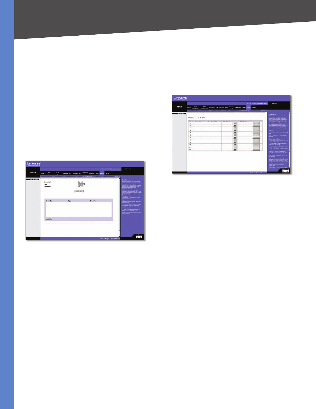
Chapter 5 Advanced Configuration
58
WebView Switches
Error •A system error has occurred.
Warning •A system warning has occurred.
Notice •The system is functioning properly, but system
notice has occurred.
Informational •Provides device information.
Debug •Provides detailed information about the
log. If a Debug error occurs, contact Customer Tech
Support.
Admin > Port Mirroring
Port mirroring monitors and mirrors network traffic by
forwarding copies of incoming and outgoing packets
from one port to a monitoring port. Port mirroring can be
used as diagnostic tool and/or a debugging feature. Port
mirroring also enables switch performance monitoring.
Admin > Port Mirroring
Network administrators configure port mirroring by
selecting a specific port to copy all packets, and different
ports from which the packets are copied.
Source Port Defines the port to which traffic is mirrored.
Type Indicates the port mode configuration for port
mirroring. The possible field values are:
RxOnly •Defines the port mirroring on receiving ports.
This is the default value.
TxOnly •Defines the port mirroring on transmitting
ports.
Both •Defines the port mirroring on both receiving
and transmitting ports.
Target Port Defines the port from which traffic is
mirrored.
Admin > Cable Test
The Cable Test screen shows you results from performance
tests on copper cables. The maximum cable length that
can be tested is 120 meters. Cables are tested when the
ports are in the down state, except for the Approximate
Cable Length test.
Admin > Cable Test
Port This is the port to which the cable is connected.
Test Result This is the test result. OK indicates that the
cable passed the test. No Cable means there is no cable
connected to the port. Open Cable means the cable is
connected on only one side. Short Cable indicates that a
short has occurred in the cable. Undefined indicates that
the test could not be properly performed.
Cable Fault Distance This is the distance from the port at
which the cable error occurred.
Last Update This is the last time the port was tested.
Test Click the Test button to perform the test.
Cable Length This is the approximate length of the cable.
The Cable Length test can be performed only when the
port is up and operating at 1Gbps.
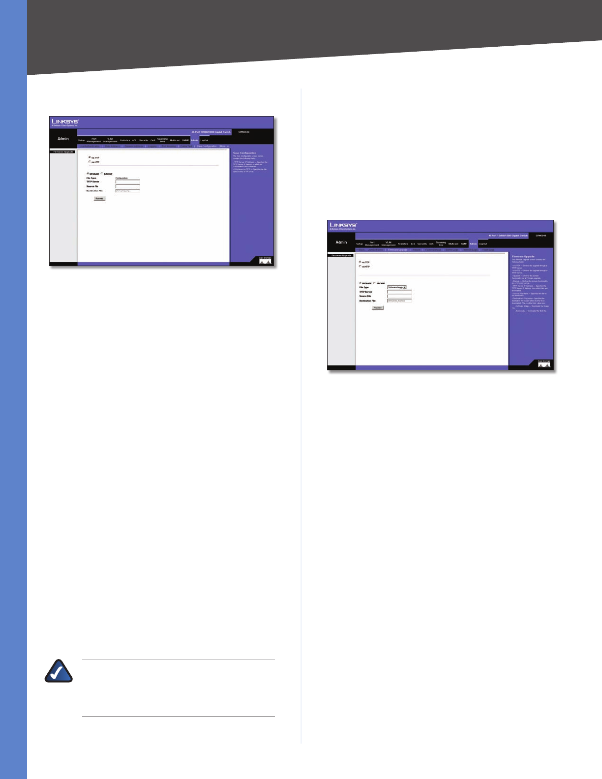
Chapter 5 Advanced Configuration
59
WebView Switches
Admin > Save Configuration
Admin > Save Configuration
Via TFTP
Upgrade Select this option to upgrade the switch from a
file located on a TFTP server.
TFTP Server •The TFTP Server IP Address that contains
the source file to upgrade from.
Source File •Specifies the name of the upgrade file on
the TFTP Server.
Backup To backup the switch configuration via TFTP,
enter the TFTP server address.
TFTP Server •Specifies the TFTP Server IP Address to
which the Configuration file will be saved.
Destination File •Specifies the name of the
configuration file. The default is StartupCfg.cfg.
Via HTTP
This HTTP Firmware Upgrade screen is used for saving
configuration information using your Web browser.
Upgrade Select this option to upgrade the switch from a
file on the local hard drive.
Source File •Type in the name and path of the file or
Browse to locate the upgrade file.
Backup
Proceed •The Proceed button is used to backup the
configuration to the local hard drive.
NOTE: When downloading a configuration file,
be sure that it is a valid configuration file. If
you have edited the file, ensure that only valid
entries have been configured.
Admin > Firmware Upgrade
After you download a new image file, the device should
be rebooted. If you are downloading a new boot image,
please follow these steps:
Download the new boot code. DO NOT RESET THE 1.
DEVICE!
Download the new software image. 2.
Reset the device now.3.
Admin > Firmware Upgrade
The Firmware Upgrade screen contains the following
fields:
via TFTP Defines the upgrade through a TFTP Server.
via HTTP Allows you to upgrade the firmware using your
Web browser.
Upgrade Defines the screen functionality as a Firmware
upgrade.
Backup Defines the screen functionality as a Firmware
backup.
TFTP Server IP Address Specifies the TFTP Server IP
Address from which files are downloaded.
Source File Name Specifies the file to be downloaded.
Destination File name Specifies the destination file type
to which the file is downloaded. The possible field values
are:
Software Image Downloads the Image file.
Boot Code Downloads the Boot file.
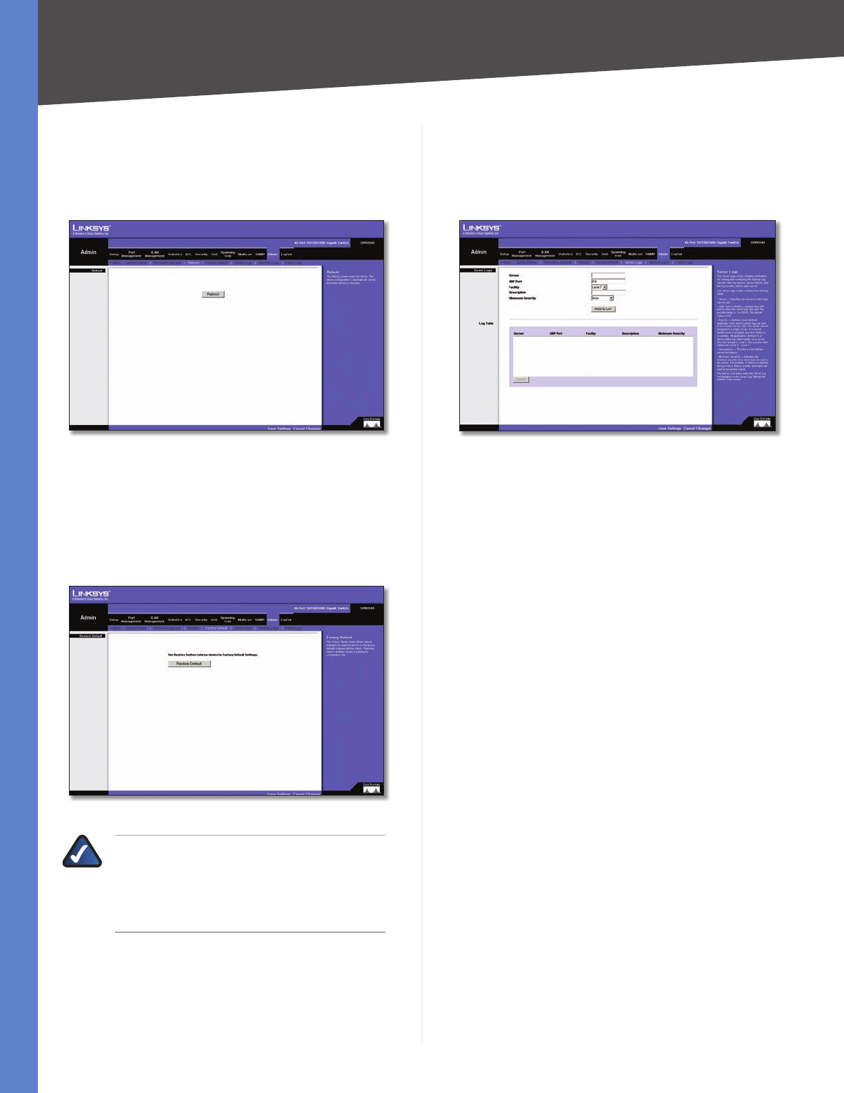
Chapter 5 Advanced Configuration
60
WebView Switches
Admin > Reboot
The Reboot screen resets the device. The device
configuration is automatically saved before the device is
rebooted.
Admin > Reboot
Admin > Factory Defaults
The Factory Reset screen allows network managers to
reset the device to the factory defaults shipped with the
switch. Restoring factory defaults results in erasing the
configuration file.
Admin > Factory Defaults
NOTE: Restoring the factory defaults will
erase all configuration settings that you have
made. You can save a backup of your current
configuration settings from Admin > Save
Configuration.
Admin > Server Logs
The Server Logs screen contains information for viewing
and configuring the Remote Log Servers. New log servers
can be defined, and the log severity sent to each server.
Admin > Server Logs
Server Specifies the server to which logs can be sent.
UDP Port Defines the UDP port to which the server logs
are sent. The possible range is 1–65,535. The default value
is 514.
Facility Defines a user-defined application from which
system logs are sent to the remote server. Only one facility
can be assigned to a single server. If a second facility level
is assigned, the first facility is overridden. All applications
defined for a device utilize the same facility on a server.
The field default is Local 7. The range is Local 0–Local 7.
Description Provides a user-defined server description.
Minimum Severity Indicates the minimum severity from
which logs are sent to the server. For example, if Notice
is selected, all logs from a Notice severity and higher are
sent to the remote server.
Use the Add to List button to add the Server Log
configuration to the Server Log Table at the bottom of the
screen.
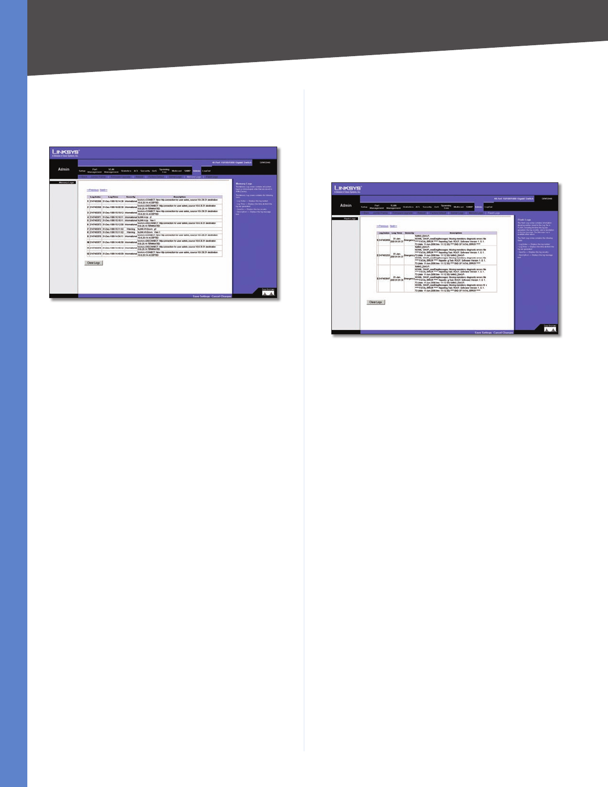
Chapter 5 Advanced Configuration
61
WebView Switches
Admin > Memory Logs
The Memory Log screen contains all system logs in a
chronological order that are saved in RAM (Cache).
Admin > Memory Logs
Log Index Displays the log number.
Log Time Displays the time at which the log was
generated.
Severity Displays the log severity.
Description Displays the log message text.
Admin > Flash Logs
The Flash Log screen contains information about log
entries saved to the Log File in FLASH, including the time
the log was generated, the log severity, and a description
of the log message. The Message Log is available after
reboot.
Admin > Flash Logs
Log Index Displays the log number.
Log Time Displays the time at which the log was
generated.
Severity Displays the log severity.
Description Displays the log message text.

62
About Gigabit Ethernet and Fiber Optic Cabling
WebView Switches
Appendix A
Appendix A:
About Gigabit Ethernet
and Fiber Optic Cabling
Gigabit Ethernet
Gigabit Ethernet runs at speeds of 1Gbps (Gigabit per
second), ten times faster than 100Mbps Fast Ethernet, but
it still integrates seamlessly with 100Mbps Fast Ethernet
hardware. Users can connect Gigabit Ethernet hardware
with either fiber optic cabling or copper Category
5e cabling, with fiber optics more suited for network
backbones. As the Gigabit standard gradually integrates
into existing networks, current computer applications will
enjoy faster access time for network data, hardware, and
Internet connections.
Fiber Optic Cabling
Fiber optic cabling is made from flexible, optically efficient
strands of glass and coated with a layer of rubber tubing,
fiber optics use photons of light instead of electrons to
send and receive data. Although fiber is physically capable
of carrying terabits of data per second, the signaling
hardware currently on the market can handle no more
than a few gigabits of data per second.
Fiber cables come with two main connector types. The
most commonly used fiber optic cable is multi-mode fiber
cable (MMF), with a 62.5 micron fiber optic core. Single-
mode fiber cabling is somewhat more efficient than multi-
mode but far more expensive, due to its smaller optic core
that helps retain the intensity of traveling light signals.
A fiber connection always require two fiber cables: one
transmits data, and the other receives it.
Each fiber optic cable is tipped with a connector that fits
into a fiber port on a network adapter, hub, or switch.
In the USA, most cables use a square SC connector that
slides and locks into place when plugged into a port or
connected to another cable. In Europe, the round ST
connector is more prevalent.
You must use the Linksys MGBT1, MGBSX1, or MGBLH1
miniGBIC modules with the Linksys Gigabit Switches.
The MGBSX1 and the MGBLH1 require fiber cabling with
LC connectors, and the MGBT1 requires a Category 5e
Ethernet cable with an RJ-45 connector.

63
Appendix B Windows Help
WebView Switches
Appendix B:
Windows Help
Almost all networking products require Microsoft
Windows. Windows is the most used operating system in
the world and comes with many features that help make
networking easier. These features can be accessed through
Windows Help and are described in this appendix.
TCP/IP
Before a computer can communicate within a network,
TCP/IP must be enabled. TCP/IP is a set of instructions, or
protocol all PCs follow to communicate over a network.
This is true for wireless networks as well. Your PCs will not
be able to utilize wireless networking without having TCP/
IP enabled. Windows Help provides complete instructions
on enabling TCP/IP.
Shared Resources
If you wish to share printers, folder, or files over your
network, Windows Help provides complete instructions
on utilizing shared resources.
Network Neighborhood/My Network Places
Other PCs on your network will appear under Network
Neighborhood or My Network Places (depending upon
the version of Windows you’re running). Windows Help
provides complete instructions on adding PCs to your
network.
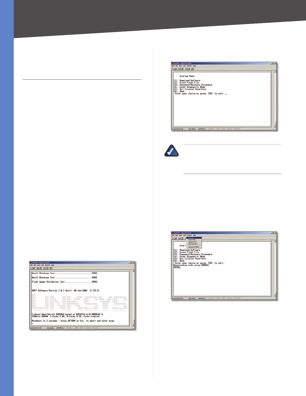
64
Downloading using Xmodem
WebView Switches
Appendix C
Appendix C:
Downloading using
Xmodem
Startup Menu Procedures
The Startup menu can be entered when booting the
device. There is a two second window of time to enter the
Startup Menu immediately after the POST test. The menu
can be accessed directly from a terminal connected to the
console port. The Startup menu procedures can be done
using the ASCII terminal or Windows HyperTerminal.
The software download procedure is performed when a
new version must be downloaded to replace corrupted
files, update or upgrade the system software. To download
software from the Startup menu:
To enter the Startup menu:
Power off your computer and Switch.1.
Connect the provided null modem cable from the 2.
COM port on your computer to the Console port on
the Switch.
Power on your computer and launch HyperTerminal, 3.
follow the instructions in Chapter 4: Configuration
Using the Console Interface to configure HyperTerminal
to connect to the Switch.
Power on the Switch and watch for the auto-boot 4.
message:
Autoboot in 2 seconds - press RETURN or Esc. to abort and
enter prom.
Auto-Boot Message
When the auto-boot message appears, press the 5. Enter
key to access the Startup menu.
Startup Menu
NOTE: If a selection is not made within 35
seconds (default), the device times out and you
will need to disconnect the power to restart the
process.
Select 6. [1] Download Software and a message will
appear Downloading code using XMODEM with
characters running across the screen.
If you do not perform the remaining steps to locate the
file for download within a certain time, the device will
reset.
Select 7. Send File from the Transfer pull-down menu.
Send File
In the Filename: field, enter the file path for the file to 8.
be downloaded or click Browse to locate the file.
Only valid files, with a *.ros or *.rfb suffix, that have
been provided by Linksys, can be downloaded.
Downloading invalid files will result in unpredictable
behavior.
Ensure that the Xmodem protocol is selected in the
Protocol: field.

65
Downloading using Xmodem
WebView Switches
Appendix C
Press 9. Send and the software is downloaded.
Download
After the software has been downloaded, the device will
reboot automatically.

66
Glossary
WebView Switches
Appendix D
Appendix D:
Glossary
This glossary contains some basic networking terms you
may come across when using this product.
WEB: For additional terms, please visit the
glossary at www.linksys.com/glossary
Access Mode Specifies the method by which user access
is granted to the system.
Access Point A device that allows wireless-equipped
computers and other devices to communicate with a
wired network. Also used to expand the range of a wireless
network.
Access Profiles Allows network managers to define
profiles and rules for accessing the device. Access to
management functions can be limited to user groups,
which are defined by the following criteria:
Ingress interfaces •
Source IP address and/or Source IP subnets. •
ACE Filters in Access Control Lists (ACL) that determine
which network traffic is forwarded. An ACE is based on the
following criteria:
Protocol •
Protocol ID •
Source Port •
Destination Port •
Wildcard Mask •
Source IP Address •
Destination IP Address •
ACL (Access Control List) Access Control Lists are
used to grant, deny, or limit access devices, features, or
applications.
Auto-negotiation Allows 10/100 Mbps or 10/100/1000
Mbps Ethernet ports to automatically establish the
optimal duplex mode, flow control, and speed.
Back Pressure A mechanism used with Half Duplex mode
that enables a port not to receive a message.
Bandwidth The transmission capacity of a given device
or network.
Bandwidth Assignments Indicates the amount of
bandwidth assigned to a specific application, user, and/or
interface.
Baud Indicates the number of signaling elements
transmitted each second.
Best Effort Indicates that traffic is assigned to the lowest
priority queue, and packet delivery is not guaranteed.
Bit A binary digit.
Boot To start a device and cause it to start executing
instructions.
Browser An application program that provides a way to
look at and interact with all the information on the World
Wide Web.
Bridge A device that connect two networks. Bridges are
hardware specific, however they are protocol independent.
Bridges operate at Layer 1 and Layer 2 levels.
Broadcast Domain Devices sets that receive broadcast
frames originating from any device within a designated
set. Routers bind Broadcast domains, because routers do
not forward broadcast frames.
Broadcast Storm An excessive amount of broadcast
messages simultaneously transmitted across a network
by a single port. Forwarded message responses are
heaped onto the network, overloading network resources
or causing the network to time out.
Burst A packet transmission at faster than normal rates.
Bursts are limited in time and only occur under specific
conditions.
Burst Size Indicates the burst size transmitted at a faster
than normal rate.
Byte A unit of data that is usually eight bits long
Cable Modem A device that connects a computer to the
cable television network, which in turn connects to the
Internet.
CBS (Committed Burst Size) Indicates the maximum
number of data bits transmitted within a specific time
interval.
CIR (Committed Information Rate) The data rate is
averaged over a minimum time increment.
Class Maps An aspect of Quality of Service system that is
comprised of an IP ACL and/or a MAC ACL. Class maps are
configured to match packet criteria, and are matched to
packets in a first-fit fashion.
Combo Ports A single logical port with two physical
connections, including an RJ-45 connection and a SFP
connection.
Communities Specifies a group of users which retain the
same system access rights.

67
Glossary
WebView Switches
Appendix D
CoS (Class of Service) The 802.1p priority scheme. CoS
provides a method for tagging packets with priority
information. A CoS value between 0-7 is added to the
Layer II header of packets, where zero is the lowest priority
and seven is the highest.
DDNS (Dynamic Domain Name System) Allows the
hosting of a website, FTP server, or e-mail server with a
fixed domain name (e.g., www.xyz.com) and a dynamic IP
address.
Default Gateway A device that forwards Internet traffic
from your local area network.
DHCP (Dynamic Host Configuration Protocol) A
networking protocol that allows administrators to assign
temporary IP addresses to network computers by “leasing”
an IP address to a user for a limited amount of time, instead
of assigning permanent IP addresses.
DHCP Clients An Internet host using DHCP to obtain
configuration parameters, such as a network address.
DHCP Server An Internet host that returns configuration
parameters to DHCP clients.
DNS (Domain Name Server) The IP address of your ISP’s
server, which translates the names of websites into IP
addresses.
Domain A specific name for a network of computers.
Download To receive a file transmitted over a network.
DSL (Digital Subscriber Line) An always-on broadband
connection over traditional phone lines.
DSCP (DiffServ Code Point) Provides a method of
tagging IP packets with QoS priority information.
Dynamic IP Address A temporary IP address assigned by
a DHCP server.
EIGRP (Enhanced Interior Gateway Routing
Protocol) Provides fast convergence, support for variable-
length subnet mask, and supports multiple network layer
protocols.
Encryption Encoding data transmitted in a network.
Ethernet IEEE standard network protocol that specifies
how data is placed on and retrieved from a common
transmission medium.
Firmware The programming code that runs a networking
device.
Flow Control Enables lower speed devices to
communicate with higher speed devices. This is
implemented by the higher speed device refraining from
sending packets.
FTP (File Transfer Protocol) A protocol used to transfer
files over a TCP/IP network.
Full Duplex The ability of a networking device to receive
and transmit data simultaneously.
GARP (General Attributes Registration
Protocol) Registers client stations into a multicast
domain.
Gateway A device that interconnects networks with
different, incompatible communications protocols.
GBIC (GigaBit Interface Converter) A hardware module
used to attach network devices to fiber-based transmission
systems. GBIC converts the serial electrical signals to serial
optical signals and vice versa.
GVRP (GARP VLAN Registration Protocol) Registers
client stations into a VLANs.
Half Duplex Data transmission that can occur in two
directions over a single line, but only one direction at a
time.
HTTP (HyperText Transport Protocol) The
communications protocol used to connect to servers on
the World Wide Web.
HTTPS (HyperText Transport Protocol Secure) An
extension to the standard HTTP protocol that provides
confidentiality by encrypting the traffic from the website.
By default this protocol uses TCP port 443.
ICMP (Internet Control Message Protocol) Allows the
gateway or destination host to communicate with the
source host. For example, to report a processing error.
IGMP (Internet Group Management Protocol) Allows
hosts to notify their local switch or router that they want
to receive transmissions assigned to a specific multicast
group.
IP (Internet Protocol) A protocol used to send data over
a network.
IP Address The address used to identify a computer or
device on a network.
IPCONFIG A Windows 2000 and XP utility that displays
the IP address for a particular networking device.
IPSec (Internet Protocol Security) A VPN protocol used
to implement secure exchange of packets at the IP layer.
ISP (Internet Service Provider) A company that provides
access to the Internet.
Jumbo Frames Enable transporting identical data in
fewer frames. Jumbo Frames reduce overhead, lower
processing time, and ensure fewer interrupts.
LAG (Link Aggregated Group) Aggregates ports or
VLANs into a single virtual port or VLAN.
LAN The computers and networking products that make
up your local network.

68
Glossary
WebView Switches
Appendix D
MAC (Media Access Control) Address The unique
address that a manufacturer assigns to each networking
device.
Mask A filter that includes or excludes certain values, for
example parts of an IP address.
Mbps (MegaBits Per Second) One million bits per
second; a unit of measurement for data transmission.
MD5 (Message Digest 5) An algorithm that produces a
128-bit hash. MD5 is a variation of MD4, and increases MD4
security. MD5 verifies the integrity of the communication
and authenticates the origin of the communication.
MDI (Media Dependent Interface) A cable used for end
stations.
MDIX (Media Dependent Interface with Crossover) A
cable used for hubs and switches.
MIB (Management Information Base) MIBs contain
information describing specific aspects of network
components.
Multicast Transmits copies of a single packet to multiple
ports.
Network A series of computers or devices connected for
the purpose of data sharing, storage, and/or transmission
between users.
NMS (Network Management System) An interface that
provides a method of managing a system.
OID (Object Identifier) Used by SNMP to identify
managed objects. In the SNMP Manager/Agent network
management paradigm, each managed object must have
an OID to identify it.
Packet A unit of data sent over a network.
Ping (Packet INternet Groper) An Internet utility used
to determine whether a particular IP address is online.
Policing Determines if traffic levels are within a specified
profile. Policing manages the maximum traffic rate used
to send or receive packets on an interface.
Port The connection point on a computer or networking
device used for plugging in cables or adapters.
Port Mirroring Monitors and mirrors network traffic by
forwarding copies of incoming and outgoing packets
from one port to a monitoring port.
Power over Ethernet (PoE) A technology enabling an
Ethernet network cable to deliver both data and power.
QoS (Quality of Service) Provides policies that contain
sets of filters (rules). QoS allows network managers
to decide how and what network traffic is forwarded
according to priorities, application types, and source and
destination addresses.
RADIUS (Remote Authentication Dial-In User
Service) A protocol that uses an authentication server to
control network access.
RJ-45 (Registered Jack-45) An Ethernet connector that
holds up to eight wires.
RMON (Remote Monitoring) Provides network
information to be collected from a single workstation.
Router A networking device that connects multiple
networks together.
RSTP (Rapid Spanning Tree Protocol) Detects and uses
network topologies that allow a faster convergence of the
spanning tree, without creating forwarding loops.
Server Any computer whose function in a network is to
provide user access to files, printing, communications,
and other services.
SMTP (Simple Mail Transfer Protocol) The standard e-
mail protocol on the Internet.
SNMP (Simple Network Management Protocol) A
widely used network monitoring and control protocol.
SSH Secure Shell. A utility that uses strong authentication
and secure communications to log in to another computer
over a network.
SSL (Secure Socket Layer) Encryption technology for
the Internet used to provide secure transactions, such as
the transmission of credit card numbers for e-commerce.
Static IP Address A fixed address assigned to a computer
or device that is connected to a network.
STP (Spanning Tree Protocol) Prevents loops in network
traffic. The Spanning Tree Protocol (STP) provides tree
topography for any arrangement of bridges. STP provides
one path between end stations on a network, eliminating
loops.
Subnet (Sub-network) Subnets are portions of a
network that share a common address component. In
TCP/IP networks, devices that share a prefix are part of
the same subnet. For example, all devices with a prefix of
157.100.100.100 are part of the same subnet.
Subnet Mask An address code that determines the size
of the network.
Switch Filters and forwards packets between LAN
segments. Switches support any packet protocol type.
TACACS+ (Terminal Access Controller Access Control
System Plus) Proprietary Cisco enhancement to Terminal
Access Controller Access Control System (TACACS). Provides
additional support for authentication, authorization, and
accounting.

69
Glossary
WebView Switches
Appendix D
TCP (Transmission Control Protocol) A network protocol
for transmitting data that requires acknowledgement
from the recipient of data sent.
TCP/IP (Transmission Control Protocol/Internet
Protocol) A set of instructions PCs use to communicate
over a network.
Telnet A user command and TCP/IP protocol used for
accessing remote PCs.
TFTP (Trivial File Transfer Protocol) A version of the
TCP/IP FTP protocol that has no directory or password
capability.
Throughput The amount of data moved successfully
from one node to another in a given time period.
Trunking Link Aggregation. Optimizes port usage by
linking a group of ports together to form a single trunk
(aggregated groups).
TX Rate Transmission Rate.
UDP (User Data Protocol) Communication protocol that
transmits packets but does not guarantee their delivery.
Upgrade To replace existing software or firmware with a
newer version.
Upload To transmit a file over a network.
URL (Uniform Resource Locator) The address of a file
located on the Internet.
VLAN (Virtual Local Area Networks) Logical subgroups
that constitute a Local Area Network (LAN). This is done in
software rather than defining a hardware solution.
WAN (Wide Area Network) Networks that cover a large
geographical area.
Wildcard Mask Specifies which IP address bits are
used, and which bits are ignored. A wild card mask
of 255.255.255.255 indicates that no bit is important.
A wildcard of 0.0.0.0 indicates that all the bits are
important.
For example, if the destination IP address is 149.36.184.198
and the wildcard mask is 255.36.184.00, the first two bits
of the IP address are used, while the last two bits are
ignored.

70
Specifications
WebView Switches
Appendix E
Appendix E: Specifications
SRW2048
Ports 48 RJ-45 connectors for
10BASE-T, 100BASE-TX and
1000BASE-T with 4 shared SFP
(miniGBIC) slots
Cabling Type UTP CAT 5 or better for
10BASE-T/100BASE-TX,
UTP CAT 5e or better for
1000BASE-T
LEDs Power, Link/Act, Speed
Performance
Switching Capacity 96 Gbps, non-blocking
MAC table size 8K
Number of VLANs 256 - Static and Dynamic
Management
Web User Interface Built-in Web UI for easy
browser-based configuration
(HTTP/HTTPS)
SNMP SNMP version v1, v2c, v3 with
support for traps
SNMP MIBs RFC1213 MIB-2, RFC2863
Interface MIB, RFC2665
Ether-like MIB, RFC1493 Bridge
MIB, RFC2674 Extended Bridge
MIB (P-bridge, Q-bridge),
RFC2819 RMON MIB (groups
1, 2, 3, 9 only), RFC2737 Entity
MIB, RFC 2618 RADIUS Client
MIB
RMON Embedded Remote Monitoring
(RMON) software agent
supports four RMON groups
(history, statistics, alarms, and
events) for enhanced traffic
management, monitoring, and
analysis
Firmware Upgrade Web Browser upgrade (HTTP
and TFTP), CLI via console or
Telnet, TFTP upgrade
Port Mirroring Traffic on a port can be
mirrored to another port
for analysis with a network
analyzer or RMON probe
Other Management RFC854 Telnet (Menu-driven
configuration)
Secure Shell (SSH) and Telnet
Management
Telnet Client
SSL security for Web UI
Switch Audit Log
DHCP Client
BootP
SNTP
Xmodem upgrade
Cable Diagnostics
PING
Traceroute
Security features
IEEE 802.1x 802.1x - RADIUS
Authentication. MD5
Encryption
Access Control Filtering: MAC-based
Availability
Link Aggregation Link Aggregation using IEEE
802.3ad LACP
Up to 8 ports in up to 8 trunks
Storm Control Broadcast, Multicast, and
Unknown Unicast
Spanning Tree IEEE 802.1d Spanning Tree,
IEEE 802.1s Multiple Spanning
Tree, IEEE 802.1w Rapid
Spanning Tree, Fast Linkover
IGMP Snooping IGMP (v1/v2) snooping
provides for fast client joins
and leaves of multicast streams
and limits bandwidth-intensive
video traffic to only the
requestors

71
Specifications
WebView Switches
Appendix E
QoS
Priority levels 4 Hardware queues
Scheduling Priority Queueing and
Weighted Round Robin (WRR)
Class of Service Port-based
802.1p VLAN priority based
IP TOS/DSCP based
IPv4 & IPv6 Traffic Class based
COS
MAC Address port security
VLAN ID
MAC Address
IP Address
Subnet Mask
Service Type
Protocol
TCP/UDP Port
Rate Limiting Ingress Policer, Egress Shaper
Layer 2
VLAN Port-based and 802.1q based
VLANs
Private VLAN Edge (PVE)
Management VLAN
HOL Blocking Head of line blocking
prevention
Jumbo frame Supports frames up to 10K
byte frames
Dynamic VLAN GVRP - Dynamic VLAN
Registration
Standards 802.3i 10BASE-T Ethernet,
802.3u 100BASE-TX Fast
Ethernet, 802.3ab 1000BASE-T
Gigabit Ethernet,
802.3z Gigabit Ethernet, 802.3x
Flow Control
ENVIRONMENTAL
Device Dimensions 430 x 44.45 x 350 mm
Weight 8.60 lb (3.9 kg)
Power Internal switching power
Certification FCC Part15 Class A, CE Class A,
UL, cUL, CE mark, CB
Operating Temperature 32 to 104°F (0 to 40°C)
Storage Temperature –4 to 158°F (–20 to 70°C)
Operating Humidity 10% to 90%
Storage Humidity 10% to 95%
SRW2016/SRW2024
Standards IEEE 802.3, 802.3u, 802.3ab,
802.3x, 802.1p, 802.1q
Ports 16 or 24 10/100/1000 RJ-45
ports and 2 shared SFP
(miniGBIC) slots
Cabling Type Cat5e or better
LEDs System, Link/Activity, Gigabit
Performance
Switching Capacity 32 or 48 Gbps, non-
blocking
MAC table size 8K
Number of VLANs 256 VLANs
Management
Web User Interface Built-in Web UI for easy
browser-based configuration
(HTTP/HTTPS)
SNMP SNMP version v1, v2c, v3 with
support for traps
SNMP MIBs RFC1213 MIB-2, RFC2863
Interface MIB, RFC2665 Ether-
like MIB, RFC1493 Bridge MIB,
RFC2674 Extended Bridge MIB
(P-bridge, Q-bridge), RFC2819
RMON MIB (groups 1, 2, 3, 9
only), RFC2737 Entity MIB,
RFC 2618 RADIUS Client MIB
RMON Embedded Remote Monitoring
(RMON) software agent
supports four RMON groups
(history, statistics, alarms, and
events)
for enhanced traffic
management, monitoring, and
analysis
Firmware Upgrade Web Browser upgrade (HTTP)
TFTP upgrade
Port Mirroring Traffic on a port can be
mirrored to another port
for analysis with a network
analyzer or RMON probe

72
Specifications
WebView Switches
Other Management RFC854 Telnet (Menu-driven
configuration)
Secure Shell (SSH) and Telnet
Management
RADIUS
TACACS+
Telnet Client
SSL security for Web UI
Switch Audit Log
DHCP Client
BootP
SNTP
Xmodem upgrade
Cable Diagnostics
PING
Traceroute
Syslog
Security Features
IEEE 802.1x 802.1x - RADIUS
Authentication. MD5
Encryption
Access Control MAC based ACL
Availability
Link Aggregation Link Aggregation using IEEE
802.3ad LACP
Up to 8 ports in up to 8 trunks
Storm Control Broadcast, Multicast, and
Unknown Unicast
Spanning Tree IEEE 802.1d Spanning Tree,
IEEE 802.1s Multiple Spanning
Tree, IEEE 802.1w Rapid
Spanning Tree, Fast Linkover
IGMP Snooping IGMP (v1/v2) snooping
provides for fast client joins
and leaves of multicast streams
and limits
bandwidth-intensive video
traffic to only the requestors.
QoS
Priority levels 4 Hardware queues
Scheduling Priority Queueing and
Weighted Round Robin (WRR)
Class of Service Port-based
802.1p VLAN priority based
IP TOS/DSCP based
IPv4 & IPv6 Traffic Class based
COS
MAC Address port security*
VLAN ID*
MAC Address*
IP Address*
Subnet Mask*
Service Type*
Protocol*
TCP/UDP Port*
Rate Limiting Ingress Policer, Egress Shaper
Layer 2
VLAN Port-based and 802.1q based
VLANs Private VLAN Edge (PVE)
Management VLAN
HOL Blocking Head of line blocking
prevention
Jumbo frame Supports frames up to 10K
byte frames
Dynamic VLAN GVRP - Dynamic VLAN
Registration
Standards 802.3i 10BASE-T Ethernet,
802.3u 100BASE-TX Fast
Ethernet, 802.3ab 1000BASE-T
Gigabit Ethernet,
802.3z Gigabit Ethernet, 802.3x
Flow Control
Environmental
Dimensions 430 x 44.5 x 350 mm
Unit Weight 7.3 lb (3.311 kg)
Power 100–240V 0.5A
Certification FCC Part15 Class A, CE Class A,
UL, cUL, CE mark, CB
Operating Temperature 32 to 104°F (0 to 40°C)
Storage Temperature –4 to 158°F (–20 to 70°C)
Operating Humidity 20% to 95% relative humidity,
noncondensing
Storage Humidity 5% to 90% noncondensing
* Denotes features found in only version 1.2 or
later of the hardware

73
Specifications
WebView Switches
SRW224G4/SRW248G4
Ports 24 or 48 RJ-45 connectors for
10BASE-T and 100BASE-TX,
4 RJ-45 connectors for 10BASE-
T/100BASE-TX/1000BASE-T
with 2 shared SFP (miniGBIC)
slots
Auto MDI/MDI-X
Autonegotiate/Manual setting
Cabling Type UTP CAT 5 or better for
10BASE-T/100BASE-TX,
UTP CAT 5e or better for
1000BASE-T
LEDs Power, Link/Act, Speed
Performance
Switching Capacity 12.8 (SRW224G4) or 17.6
(SRW248G4) Gig non-blocking
MAC table size 8K
Number of VLANs 256 - Static
Management
Web User Interface Built-in Web UI for easy
browser-based configuration
(HTTP/HTTPS)
SNMP SNMP version 1, 2, 3 with
support for traps
SNMP MIBs RFC1213 MIB-2, RFC2863
Interface MIB, RFC2665 Ether-
like MIB, RFC1493 Bridge MIB,
RFC2674 Extended Bridge MIB
(P-bridge, Q-bridge), RFC2819
RMON MIB (groups 1, 2, 3, 9
only), RFC 2618 RADIUS Client
MIB
RMON Embedded Remote Monitoring
(RMON) software agent
supports four RMON groups
(history, statistics, alarms, and
events) for enhanced traffic
management, monitoring, and
analysis
Firmware Upgrade Web Browser upgrade (HTTP)
TFTP upgrade
Port Mirroring Traffic on a port can be
mirrored to another port
for analysis with a network
analyzer or RMON probe
Other Management RFC854 Telnet (Menu-driven
configuration)
Secure Shell (SSH) and Telnet
Management
Telnet Client
SSL security for Web UI
Switch Audit Log
DHCP Client
BootP
SNTP
Xmodem upgrade
Cable Diagnostics
PING
Traceroute
Syslog
Security
IEEE 802.1x 802.1x - RADIUS
Authentication. MD5
Encryption
Access Control Filtering: MAC-based
Availability
Link Aggregation Link Aggregation using IEEE
802.3ad LACP
Up to 8 ports in up to 8 trunks
Storm Control Broadcast, Multicast, and
Unknown Unicast
Spanning Tree IEEE 802.1d Spanning Tree,
IEEE 802.1s Multiple Spanning
Tree, IEEE 802.1w Rapid
Spanning Tree, Fast Linkover
IGMP Snooping IGMP (v1/v2) snooping
provides for fast client joins
and leaves of multicast streams
and limits bandwidth-intensive
video traffic to only the
requestors

74
Specifications
WebView Switches
QoS
Priority levels 4 Hardware queues
Scheduling Priority Queueing and
Weighted Round Robin (WRR)
Class of Service Port-based
802.1p VLAN priority based
IP TOS/DSCP based
IPv4 & IPv6 Traffic Class based
COS
MAC Address port security†
VLAN ID*
MAC Address*
IP Address*
Subnet Mask*
Service Type*
Protocol*
TCP/UDP Port*
Rate Limiting Ingress Policer, Egress Shaper
Layer 2
VLAN Port-based and 802.1q based
VLANs
Private VLAN Edge (PVE)
Management VLAN
HOL Blocking Head of line blocking
prevention
Mini jumbo frame Supports frames up to 1600
bytes
Dynamic VLAN GVRP - Dynamic VLAN
Registration
Standards 802.3i 10BASE-T Ethernet,
802.3u 100BASE-TX Fast
Ethernet, 802.3ab 1000BASE-T
Gigabit Ethernet, 802.3z
Gigabit Ethernet, 802.3x Flow
Control
† Denotes features found in only version 1.1 or
later of the hardware
Environmental
Dimensions SRW224G4 - 430 x 44 x 203 mm
H x W x D SRW248G4 - 430 x 44 x 350 mm
Weight SRW224G4 - 4.41 lb (2 kg)
SRW248G4 - 8.60 lb (3.9 kg)
Power Internal Switching Power
Certification FCC Part15 Class A, CE Class A,
UL, cUL, CE mark, CB
Operating Temp. 0 to 40°C
Storage Temp. –20 to 70°C
Operating Humidity 10% to 90%
Storage Humidity 10% to 95%

75
Appendix F Warranty Information
WebView Switches
free of vulnerability to intrusion or attack. The product
may include or be bundled with third party software or
service offerings. This limited warranty shall not apply to
such third party software or service offerings. This limited
warranty does not guarantee any continued availability
of a third party’s service for which this product’s use or
operation may require.
TO THE EXTENT NOT PROHIBITED BY LAW, ALL IMPLIED
WARRANTIES AND CONDITIONS OF MERCHANTABILITY,
SATISFACTORY QUALITY OR FITNESS FOR A PARTICULAR
PURPOSE ARE LIMITED TO THE DURATION OF THE
WARRANTY PERIOD. ALL OTHER EXPRESS OR IMPLIED
CONDITIONS, REPRESENTATIONS AND WARRANTIES,
INCLUDING, BUT NOT LIMITED TO, ANY IMPLIED
WARRANTY OF NON-INFRINGEMENT, ARE DISCLAIMED.
Some jurisdictions do not allow limitations on how long
an implied warranty lasts, so the above limitation may not
apply to you. This limited warranty gives you specific legal
rights, and you may also have other rights which vary by
jurisdiction.
TO THE EXTENT NOT PROHIBITED BY LAW, IN NO EVENT
WILL LINKSYS BE LIABLE FOR ANY LOST DATA, REVENUE
OR PROFIT, OR FOR SPECIAL, INDIRECT, CONSEQUENTIAL,
INCIDENTAL OR PUNITIVE DAMAGES, REGARDLESS OF THE
THEORY OF LIABILITY (INCLUDING NEGLIGENCE), ARISING
OUT OF OR RELATED TO THE USE OF OR INABILITY TO
USE THE PRODUCT (INCLUDING ANY SOFTWARE), EVEN
IF LINKSYS HAS BEEN ADVISED OF THE POSSIBILITY OF
SUCH DAMAGES. IN NO EVENT WILL LINKSYS’ LIABILITY
EXCEED THE AMOUNT PAID BY YOU FOR THE PRODUCT.
The foregoing limitations will apply even if any warranty
or remedy provided under this limited warranty fails of
its essential purpose. Some jurisdictions do not allow
the exclusion or limitation of incidental or consequential
damages, so the above limitation or exclusion may not
apply to you.
Obtaining Warranty Service
If you have a question about your product or experience a
problem with it, please go to www.linksys.com/support
where you will find a variety of online support tools and
information to assist you with your product. If the product
proves defective during the Warranty Period, contact the
Value Added Reseller (VAR) from whom you purchased
the product or Linksys Technical Support for instructions
on how to obtain warranty service. The telephone number
for Linksys Technical Support in your area can be found
in the product User Guide and at www.linksys.com.
Have your product serial number and proof of purchase
on hand when calling. A DATED PROOF OF ORIGINAL
PURCHASE IS REQUIRED TO PROCESS WARRANTY CLAIMS.
If you are requested to return your product, you will be
given a Return Materials Authorization (RMA) number. You
are responsible for properly packaging and shipping your
Appendix F:
Warranty Information
Limited Warranty
Linksys warrants this Linksys hardware product against
defects in materials and workmanship under normal
use for the Warranty Period, which begins on the
date of purchase by the original end-user purchaser
and lasts for the period specified for this product at
www.linksys.com/warranty. The internet URL address
and the web pages referred to herein may be updated by
Linksys from time to time; the version in effect at the date
of purchase shall apply.
This limited warranty is non-transferable and extends only
to the original end-user purchaser. Your exclusive remedy
and Linksys’ entire liability under this limited warranty
will be for Linksys, at its option, to (a) repair the product
with new or refurbished parts, (b) replace the product
with a reasonably available equivalent new or refurbished
Linksys product, or (c) refund the purchase price of the
product less any rebates. Any repaired or replacement
products will be warranted for the remainder of the
original Warranty Period or thirty (30) days, whichever is
longer. All products and parts that are replaced become
the property of Linksys.
Exclusions and Limitations
This limited warranty does not apply if: (a) the product
assembly seal has been removed or damaged, (b) the
product has been altered or modified, except by Linksys, (c)
the product damage was caused by use with non-Linksys
products, (d) the product has not been installed, operated,
repaired, or maintained in accordance with instructions
supplied by Linksys, (e) the product has been subjected to
abnormal physical or electrical stress, misuse, negligence,
or accident, (f) the serial number on the Product has been
altered, defaced, or removed, or (g) the product is supplied
or licensed for beta, evaluation, testing or demonstration
purposes for which Linksys does not charge a purchase
price or license fee.
ALL SOFTWARE PROVIDED BY LINKSYS WITH THE
PRODUCT, WHETHER FACTORY LOADED ON THE
PRODUCT OR CONTAINED ON MEDIA ACCOMPANYING
THE PRODUCT, IS PROVIDED “AS IS” WITHOUT WARRANTY
OF ANY KIND. Without limiting the foregoing, Linksys does
not warrant that the operation of the product or software
will be uninterrupted or error free. Also, due to the
continual development of new techniques for intruding
upon and attacking networks, Linksys does not warrant
that the product, software or any equipment, system or
network on which the product or software is used will be

76
Appendix F Warranty Information
WebView Switches
product to Linksys at your cost and risk. You must include
the RMA number and a copy of your dated proof of
original purchase when returning your product. Products
received without a RMA number and dated proof of
original purchase will be rejected. Do not include any
other items with the product you are returning to Linksys.
Defective product covered by this limited warranty will be
repaired or replaced and returned to you without charge.
Customers outside of the United States of America and
Canada are responsible for all shipping and handling
charges, custom duties, VAT and other associated taxes
and charges. Repairs or replacements not covered under
this limited warranty will be subject to charge at Linksys’
then-current rates.
Technical Support
This limited warranty is neither a service nor a support
contract. Information about Linksys’ current technical
support offerings and policies (including any fees for
support services) can be found at:
www.linksys.com/support.
This limited warranty is governed by the laws of the
jurisdiction in which the Product was purchased by you.
Please direct all inquiries to: Linksys, P.O. Box 18558, Irvine,
CA 92623.
77
Regulatory Information
WebView Switches
Appendix G
Appendix G:
Regulatory Information
FCC Statement
This equipment has been tested and complies with
the specifications for a Class A digital device, pursuant
to Part 15 of the FCC Rules. Operation is subject to the
following two conditions: (1) this device may not cause
harmful interference, and (2) this device must accept any
interference received, including interference that may
cause undesired operation. These limits are designed
to provide reasonable protection against harmful
interference when equipment is operated in a commercial
environment. This equipment generates, uses, and can
radiate radio frequency energy and, if not installed and
used in accordance with the instruction manual, may
cause harmful interference to radio communications.
Operation of this equipment in a residential area is likely to
cause harmful interference in which case the user will be
required to correct the interference at his own expense.
WARNING: You are cautioned that changes or
modifications not expressly approved by the
party responsible for compliance could void
your authority to operate the equipment.
Safety Notices
Caution: To reduce the risk of fire, use only No.26 AWG •
or larger telecommunication line cord.
Do not use this product near water, for example, in a •
wet basement or near a swimming pool.
Avoid using this product during an electrical storm. •
There may be a remote risk of electric shock from
lightning.
WARNING: This product contains lead, known
to the State of California to cause cancer, and
birth defects or other reproductive harm. Wash
hands after handling.
Industry Canada Statement
This Class B digital apparatus complies with Canadian
ICES-003.
Operation is subject to the following two conditions:
This device may not cause interference and1.
This device must accept any interference, including 2.
interference that may cause undesired operation of
the device.
Avis d’Industrie Canada
Cet appareil numérique de la classe B est conforme à la
norme NMB-003 du Canada.
Le fonctionnement est soumis aux conditions suivantes :
Ce périphérique ne doit pas causer d’interférences; 1.
Ce périphérique doit accepter toutes les interférences 2.
reçues, y compris celles qui risquent d’entraîner un
fonctionnement indésirable.

78
Regulatory Information
WebView Switches
Appendix G
User Information for Consumer Products
Covered by EU Directive 2002/96/EC on
Waste Electric and Electronic Equipment
(WEEE)
This document contains important information for users
with regards to the proper disposal and recycling of
Linksys products. Consumers are required to comply with
this notice for all electronic products bearing the following
symbol:
English - Environmental Information for Customers in
the European Union
European Directive 2002/96/EC requires that the equipment
bearing this symbol on the product and/or its packaging must
not be disposed of with unsorted municipal waste. The symbol
indicates that this product should be disposed of separately
from regular household waste streams. It is your responsibility to
dispose of this and other electric and electronic equipment via
designated collection facilities appointed by the government or
local authorities. Correct disposal and recycling will help prevent
potential negative consequences to the environment and
human health. For more detailed information about the disposal
of your old equipment, please contact your local authorities,
waste disposal service, or the shop where you purchased the
product.
Български (Bulgarian) - Информация относно
опазването на околната среда за потребители в
Европейския съюз
Европейска директива 2002/96/EC изисква уредите, носещи
този символ върху изделието и/или опаковката му, да не
се изхвърля т с несортирани битови отпадъци. Символът
обозначава, че изделието трябва да се изхвърля отделно от
сметосъбирането на обикновените битови отпадъци. Ваша
е отговорността този и другите електрически и електронни
уреди да се изхвърлят в предварително определени от
държавните или общински органи специализирани пунктове
за събиране. Правилното изхвърляне и рециклиране
ще спомогнат да се предотвратят евентуални вредни за
околната среда и здравето на населението последствия. За
по-подробна информация относно изхвърлянето на вашите
стари уреди се обърнете към местните власти, службите за
сметосъбиране или магазина, от който сте закупили уреда.
Ceština (Czech) - Informace o ochraně životního
prostředí pro zákazníky v zemích Evropské unie
Evropská směrnice 2002/96/ES zakazuje, aby zařízení označené
tímto symbolem na produktu anebo na obalu bylo likvidováno
s netříděným komunálním odpadem. Tento symbol udává,
že daný produkt musí být likvidován odděleně od běžného
komunálního odpadu. Odpovídáte za likvidaci tohoto produktu
a dalších elektrických a elektronických zařízení prostřednictvím
určených sběrných míst stanovených vládou nebo místními
úřady. Správná likvidace a recyklace pomáhá předcházet
potenciálním negativním dopadům na životní prostředí a lidské
zdraví. Podrobnější informace o likvidaci starého vybavení si
laskavě vyžádejte od místních úřadů, podniku zabývajícího se
likvidací komunálních odpadů nebo obchodu, kde jste produkt
zakoupili.
Dansk (Danish) - Miljøinformation for kunder i EU
EU-direktiv 2002/96/EF kræver, at udstyr der bærer dette symbol
på produktet og/eller emballagen ikke må bortskaffes som
usorteret kommunalt affald. Symbolet betyder, at dette produkt
skal bortskaffes adskilt fra det almindelige husholdningsaffald.
Det er dit ansvar at bortskaffe dette og andet elektrisk og
elektronisk udstyr via bestemte indsamlingssteder udpeget
af staten eller de lokale myndigheder. Korrekt bortskaffelse
og genvinding vil hjælpe med til at undgå mulige skader for
miljøet og menneskers sundhed. Kontakt venligst de lokale
myndigheder, renovationstjenesten eller den butik, hvor du
har købt produktet, angående mere detaljeret information om
bortskaffelse af dit gamle udstyr.
Deutsch (German) - Umweltinformation für Kunden
innerhalb der Europäischen Union
Die Europäische Richtlinie 2002/96/EC verlangt, dass technische
Ausrüstung, die direkt am Gerät und/oder an der Verpackung mit
diesem Symbol versehen ist , nicht zusammen mit unsortiertem
Gemeindeabfall entsorgt werden darf. Das Symbol weist darauf
hin, dass das Produkt von regulärem Haushaltmüll getrennt
entsorgt werden sollte. Es liegt in Ihrer Verantwortung, dieses
Gerät und andere elektrische und elektronische Geräte über
die dafür zuständigen und von der Regierung oder örtlichen
Behörden dazu bestimmten Sammelstellen zu entsorgen.
Ordnungsgemäßes Entsorgen und Recyceln trägt dazu bei,
potentielle negative Folgen für Umwelt und die menschliche
Gesundheit zu vermeiden. Wenn Sie weitere Informationen zur
Entsorgung Ihrer Altgeräte benötigen, wenden Sie sich bitte an
die örtlichen Behörden oder städtischen Entsorgungsdienste
oder an den Händler, bei dem Sie das Produkt erworben haben.

79
Regulatory Information
WebView Switches
Appendix G
Eesti (Estonian) - Keskkonnaalane informatsioon
Euroopa Liidus asuvatele klientidele
Euroopa Liidu direktiivi 2002/96/EÜ nõuete kohaselt on
seadmeid, millel on tootel või pakendil käesolev sümbol ,
keelatud kõrvaldada koos sorteerimata olmejäätmetega. See
sümbol näitab, et toode tuleks kõrvaldada eraldi tavalistest
olmejäätmevoogudest. Olete kohustatud kõrvaldama käesoleva
ja ka muud elektri- ja elektroonikaseadmed riigi või kohalike
ametiasutuste poolt ette nähtud kogumispunktide kaudu.
Seadmete korrektne kõrvaldamine ja ringlussevõtt aitab vältida
võimalikke negatiivseid tagajärgi keskkonnale ning inimeste
tervisele. Vanade seadmete kõrvaldamise kohta täpsema
informatsiooni saamiseks võtke palun ühendust kohalike
ametiasutustega, jäätmekäitlusfirmaga või kauplusega, kust te
toote ostsite.
Español (Spanish) - Información medioambiental para
clientes de la Unión Europea
La Directiva 2002/96/CE de la UE exige que los equipos que
lleven este símbolo en el propio aparato y/o en su embalaje
no deben eliminarse junto con otros residuos urbanos no
seleccionados. El símbolo indica que el producto en cuestión
debe separarse de los residuos domésticos convencionales con
vistas a su eliminación. Es responsabilidad suya desechar este y
cualesquiera otros aparatos eléctricos y electrónicos a través de
los puntos de recogida que ponen a su disposición el gobierno y
las autoridades locales. Al desechar y reciclar correctamente estos
aparatos estará contribuyendo a evitar posibles consecuencias
negativas para el medio ambiente y la salud de las personas. Si
desea obtener información más detallada sobre la eliminación
segura de su aparato usado, consulte a las autoridades locales,
al servicio de recogida y eliminación de residuos de su zona o
pregunte en la tienda donde adquirió el producto.
ξλληνικά (Greek) - Στοιχεία περιβαλλοντικής
προστασίας για πελάτες εντός της Ευρωπαϊκής
Ένωσης
Η Κοινοτική Οδηγία 2002/96/EC απαιτεί ότι ο εξοπλισμός ο οποίος
φέρει αυτό το σύμβολο στο προϊόν και/ή στη συσκευασία
του δεν πρέπει να απορρίπτεται μαζί με τα μικτά κοινοτικά
απορρίμματα. Το σύμβολο υποδεικνύει ότι αυτό το προϊόν θα
πρέπει να απορρίπτεται ξεχωριστά από τα συνήθη οικιακά
απορρίμματα. Είστε υπεύθυνος για την απόρριψη του παρόντος
και άλλου ηλεκτρικού και ηλεκτρονικού εξοπλισμού μέσω των
καθορισμένων εγκαταστάσεων συγκέντρωσης απορριμμάτων οι
οποίες παρέχονται από το κράτος ή τις αρμόδιες τοπικές αρχές.
Η σωστή απόρριψη και ανακύκλωση συμβάλλει στην πρόληψη
πιθανών αρνητικών συνεπειών για το περιβάλλον και την υγεία.
Για περισσότερες πληροφορίες σχετικά με την απόρριψη του
παλιού σας εξοπλισμού, παρακαλώ επικοινωνήστε με τις τοπικές
αρχές, τις υπηρεσίες απόρριψης ή το κατάστημα από το οποίο
αγοράσατε το προϊόν.
Français (French) - Informations environnementales
pour les clients de l’Union européenne
La directive européenne 2002/96/CE exige que l’équipement
sur lequel est apposé ce symbole sur le produit et/ou son
emballage ne soit pas jeté avec les autres ordures ménagères. Ce
symbole indique que le produit doit être éliminé dans un circuit
distinct de celui pour les déchets des ménages. Il est de votre
responsabilité de jeter ce matériel ainsi que tout autre matériel
électrique ou électronique par les moyens de collecte indiqués
par le gouvernement et les pouvoirs publics des collectivités
territoriales. L’élimination et le recyclage en bonne et due forme
ont pour but de lutter contre l’impact néfaste potentiel de ce
type de produits sur l’environnement et la santé publique. Pour
plus d’informations sur le mode d’élimination de votre ancien
équipement, veuillez prendre contact avec les pouvoirs publics
locaux, le service de traitement des déchets, ou l’endroit où vous
avez acheté le produit.
Italiano (Italian) - Informazioni relative all’ambiente
per i clienti residenti nell’Unione Europea
La direttiva europea 2002/96/EC richiede che le apparecchiature
contrassegnate con questo simbolo sul prodotto e/o
sull’imballaggio non siano smaltite insieme ai rifiuti urbani
non differenziati. Il simbolo indica che questo prodotto non
deve essere smaltito insieme ai normali rifiuti domestici. È
responsabilità del proprietario smaltire sia questi prodotti sia
le altre apparecchiature elettriche ed elettroniche mediante
le specifiche strutture di raccolta indicate dal governo o dagli
enti pubblici locali. Il corretto smaltimento ed il riciclaggio
aiuteranno a prevenire conseguenze potenzialmente negative
per l’ambiente e per la salute dell’essere umano. Per ricevere
informazioni più dettagliate circa lo smaltimento delle vecchie
apparecchiature in Vostro possesso, Vi invitiamo a contattare gli
enti pubblici di competenza, il servizio di smaltimento rifiuti o il
negozio nel quale avete acquistato il prodotto.
Latviešu valoda (Latvian) - Ekoloģiska informācija
klientiem Eiropas Savienības jurisdikcijā
Direktīvā 2002/96/EK ir prasība, ka aprīkojumu, kam pievienota
zīme uz paša izstrādājuma vai uz tā iesaiņojuma, nedrīkst
izmest nešķirotā veidā kopā ar komunālajiem atkritumiem
(tiem, ko rada vietēji iedzīvotāji un uzņēmumi). Šī zīme nozīmē
to, ka šī ierīce ir jāizmet atkritumos tā, lai tā nenonāktu kopā ar
parastiem mājsaimniecības atkritumiem. Jūsu pienākums ir šo
un citas elektriskas un elektroniskas ierīces izmest atkritumos,
izmantojot īpašus atkritumu savākšanas veidus un līdzekļus, ko
nodrošina valsts un pašvaldību iestādes. Ja izmešana atkritumos
un pārstrāde tiek veikta pareizi, tad mazinās iespējamais
kaitējums dabai un cilvēku veselībai. Sīkākas ziņas par
novecojuša aprīkojuma izmešanu atkritumos jūs varat saņemt
vietējā pašvaldībā, atkritumu savākšanas dienestā, kā arī veikalā,
kur iegādājāties šo izstrādājumu.

80
Regulatory Information
WebView Switches
Appendix G
Lietuvškai (Lithuanian) - Aplinkosaugos informacija,
skirta Europos Sąjungos vartotojams
Europos direktyva 2002/96/EC numato, kad įrangos, kuri ir
kurios pakuotė yra pažymėta šiuo simboliu (įveskite simbolį),
negalima šalinti kartu su nerūšiuotomis komunalinėmis
atliekomis. Šis simbolis rodo, kad gaminį reikia šalinti atskirai
nuo bendro buitinių atliekų srauto. Jūs privalote užtikrinti, kad
ši ir kita elektros ar elektroninė įranga būtų šalinama per tam
tikras nacionalinės ar vietinės valdžios nustatytas atliekų rinkimo
sistemas. Tinkamai šalinant ir perdirbant atliekas, bus išvengta
galimos žalos aplinkai ir žmonių sveikatai. Daugiau informacijos
apie jūsų senos įrangos šalinimą gali pateikti vietinės valdžios
institucijos, atliekų šalinimo tarnybos arba parduotuvės, kuriose
įsigijote tą gaminį.
Malti (Maltese) - Informazzjoni Ambjentali għal Klijenti
fl-Unjoni Ewropea
Id-Direttiva Ewropea 2002/96/KE titlob li t-tagħmir li jkun fih is-
simbolu fuq il-prodott u/jew fuq l-ippakkjar ma jistax jintrema
ma’ skart muniċipali li ma ġiex isseparat. Is-simbolu jindika
li dan il-prodott għandu jintrema separatament minn ma’ l-
iskart domestiku regolari. Hija responsabbiltà tiegħek li tarmi
dan it-tagħmir u kull tagħmir ieħor ta’ l-elettriku u elettroniku
permezz ta’ faċilitajiet ta’ ġbir appuntati apposta mill-gvern jew
mill-awtoritajiet lokali. Ir-rimi b’mod korrett u r-riċiklaġġ jgħin
jipprevjeni konsegwenzi negattivi potenzjali għall-ambjent u
għas-saħħa tal-bniedem. Għal aktar informazzjoni dettaljata
dwar ir-rimi tat-tagħmir antik tiegħek, jekk jogħġbok ikkuntattja
lill-awtoritajiet lokali tiegħek, is-servizzi għar-rimi ta’ l-iskart, jew
il-ħanut minn fejn xtrajt il-prodott.
Magyar (Hungarian) - Környezetvédelmi információ az
európai uniós vásárlók számára
A 2002/96/EC számú európai uniós irányelv megkívánja, hogy
azokat a termékeket, amelyeken, és/vagy amelyek csomagolásán
az alábbi címke megjelenik, tilos a többi szelektálatlan lakossági
hulladékkal együtt kidobni. A címke azt jelöli, hogy az adott
termék kidobásakor a szokványos háztartási hulladékelszállítási
rendszerektõl elkülönített eljárást kell alkalmazni. Az Ön
felelõssége, hogy ezt, és más elektromos és elektronikus
berendezéseit a kormányzati vagy a helyi hatóságok által
kijelölt gyűjtõredszereken keresztül számolja fel. A megfelelõ
hulladékfeldolgozás segít a környezetre és az emberi egészségre
potenciálisan ártalmas negatív hatások megelõzésében. Ha
elavult berendezéseinek felszámolásához további részletes
információra van szüksége, kérjük, lépjen kapcsolatba a helyi
hatóságokkal, a hulladékfeldolgozási szolgálattal, vagy azzal
üzlettel, ahol a terméket vásárolta.
Nederlands (Dutch) - Milieu-informatie voor klanten
in de Europese Unie
De Europese Richtlijn 2002/96/EC schrijft voor dat apparatuur die
is voorzien van dit symbool op het product of de verpakking,
niet mag worden ingezameld met niet-gescheiden huishoudelijk
afval. Dit symbool geeft aan dat het product apart moet worden
ingezameld. U bent zelf verantwoordelijk voor de vernietiging
van deze en andere elektrische en elektronische apparatuur via de
daarvoor door de landelijke of plaatselijke overheid aangewezen
inzamelingskanalen. De juiste vernietiging en recycling van
deze apparatuur voorkomt mogelijke negatieve gevolgen voor
het milieu en de gezondheid. Voor meer informatie over het
vernietigen van uw oude apparatuur neemt u contact op met
de plaatselijke autoriteiten of afvalverwerkingsdienst, of met de
winkel waar u het product hebt aangeschaft.
Norsk (Norwegian) - Miljøinformasjon for kunder i EU
EU-direktiv 2002/96/EF krever at utstyr med følgende symbol
avbildet på produktet og/eller pakningen, ikke må kastes
sammen med usortert avfall. Symbolet indikerer at dette
produktet skal håndteres atskilt fra ordinær avfallsinnsamling
for husholdningsavfall. Det er ditt ansvar å kvitte deg med
dette produktet og annet elektrisk og elektronisk avfall via egne
innsamlingsordninger slik myndighetene eller kommunene
bestemmer. Korrekt avfallshåndtering og gjenvinning vil
være med på å forhindre mulige negative konsekvenser for
miljø og helse. For nærmere informasjon om håndtering av
det kasserte utstyret ditt, kan du ta kontakt med kommunen,
en innsamlingsstasjon for avfall eller butikken der du kjøpte
produktet.
Polski (Polish) - Informacja dla klientów w Unii
Europejskiej o przepisach dotyczących ochrony
środowiska
Dyrektywa Europejska 2002/96/EC wymaga, aby sprzęt
oznaczony symbolem znajdującym się na produkcie i/lub jego
opakowaniu nie był wyrzucany razem z innymi niesortowanymi
odpadami komunalnymi. Symbol ten wskazuje, że produkt
nie powinien być usuwany razem ze zwykłymi odpadami z
gospodarstw domowych. Na Państwu spoczywa obowiązek
wyrzucania tego i innych urządzeń elektrycznych oraz
elektronicznych w punktach odbioru wyznaczonych przez władze
krajowe lub lokalne. Pozbywanie się sprzętu we właściwy sposób
i jego recykling pomogą zapobiec potencjalnie negatywnym
konsekwencjom dla środowiska i zdrowia ludzkiego. W celu
uzyskania szczegółowych informacji o usuwaniu starego sprzętu,
prosimy zwrócić się do lokalnych władz, służb oczyszczania
miasta lub sklepu, w którym produkt został nabyty.

81
Regulatory Information
WebView Switches
Appendix G
Português (Portuguese) - Informação ambiental para
clientes da União Europeia
A Directiva Europeia 2002/96/CE exige que o equipamento
que exibe este símbolo no produto e/ou na sua embalagem
não seja eliminado junto com os resíduos municipais não
separados. O símbolo indica que este produto deve ser
eliminado separadamente dos resíduos domésticos regulares.
É da sua responsabilidade eliminar este e qualquer outro
equipamento eléctrico e electrónico através das instalações
de recolha designadas pelas autoridades governamentais ou
locais. A eliminação e reciclagem correctas ajudarão a prevenir
as consequências negativas para o ambiente e para a saúde
humana. Para obter informações mais detalhadas sobre a
forma de eliminar o seu equipamento antigo, contacte as
autoridades locais, os serviços de eliminação de resíduos ou o
estabelecimento comercial onde adquiriu o produto.
Română (Romanian) - Informaţii de mediu pentru
clienţii din Uniunea Europeană
Directiva europeană 2002/96/CE impune ca echipamentele care
prezintă acest simbol pe produs şi/sau pe ambalajul acestuia să
nu fie casate împreună cu gunoiul menajer municipal. Simbolul
indică faptul că acest produs trebuie să fie casat separat de
gunoiul menajer obişnuit. Este responsabilitatea dvs. să casaţi
acest produs şi alte echipamente electrice şi electronice prin
intermediul unităţilor de colectare special desemnate de guvern
sau de autorităţile locale. Casarea şi reciclarea corecte vor ajuta
la prevenirea potenţialelor consecinţe negative asupra sănătăţii
mediului şi a oamenilor. Pentru mai multe informaţii detaliate
cu privire la casarea acestui echipament vechi, contactaţi
autorităţile locale, serviciul de salubrizare sau magazinul de la
care aţi achiziţionat produsul.
Slovenčina (Slovak) - Informácie o ochrane životného
prostredia pre zákazníkov v Európskej únii
Podľa európskej smernice 2002/96/ES zariadenie s týmto
symbolom na produkte a/alebo jeho balení nesmie byť
likvidované spolu s netriedeným komunálnym odpadom.
Symbol znamená, že produkt by sa mal likvidovať oddelene
od bežného odpadu z domácností. Je vašou povinnosťou
likvidovať toto i ostatné elektrické a elektronické zariadenia
prostredníctvom špecializovaných zberných zariadení určených
vládou alebo miestnymi orgánmi. Správna likvidácia a recyklácia
pomôže zabrániť prípadným negatívnym dopadom na životné
prostredie a zdravie ľudí. Ak máte záujem o podrobnejšie
informácie o likvidácii starého zariadenia, obráťte sa, prosím, na
miestne orgány, organizácie zaoberajúce sa likvidáciou odpadov
alebo obchod, v ktorom ste si produkt zakúpili.
Slovenčina (Slovene) - Okoljske informacije za stranke
v Evropski uniji
Evropska direktiva 2002/96/EC prepoveduje odlaganje opreme,
označene s tem simbolom – na izdelku in/ali na embalaži – med
običajne, nerazvrščene odpadke. Ta simbol opozarja, da je treba
izdelek odvreči ločeno od preostalih gospodinjskih odpadkov.
Vaša odgovornost je, da to in preostalo električno in elektronsko
opremo odnesete na posebna zbirališča, ki jih določijo
državne ustanove ali lokalna uprava. S pravilnim odlaganjem
in recikliranjem boste preprečili morebitne škodljive vplive na
okolje in zdravje ljudi. Če želite izvedeti več o odlaganju stare
opreme, se obrnite na lokalno upravo, odpad ali trgovino, kjer
ste izdelek kupili.
Suomi (Finnish) - Ympäristöä koskevia tietoja EU-
alueen asiakkaille
EU-direktiivi 2002/96/EY edellyttää, että jos laitteistossa on tämä
symboli itse tuotteessa ja/tai sen pakkauksessa, laitteistoa
ei saa hävittää lajittelemattoman yhdyskuntajätteen mukana.
Symboli merkitsee sitä, että tämä tuote on hävitettävä erillään
tavallisesta kotitalousjätteestä. Sinun vastuullasi on hävittää
tämä elektroniikkatuote ja muut vastaavat elektroniikkatuotteet
viemällä tuote tai tuotteet viranomaisten määräämään
keräyspisteeseen. Laitteiston oikea hävittäminen estää
mahdolliset kielteiset vaikutukset ympäristöön ja ihmisten
terveyteen. Lisätietoja vanhan laitteiston oikeasta hävitystavasta
saa paikallisilta viranomaisilta, jätteenhävityspalvelusta tai siitä
myymälästä, josta ostit tuotteen.
Svenska (Swedish) - Miljöinformation för kunder i
Europeiska unionen
Det europeiska direktivet 2002/96/EC kräver att utrustning med
denna symbol på produkten och/eller förpackningen inte får
kastas med osorterat kommunalt avfall. Symbolen visar att denna
produkt bör kastas efter att den avskiljts från vanligt hushållsavfall.
Det faller på ditt ansvar att kasta denna och annan elektrisk och
elektronisk utrustning på fastställda insamlingsplatser utsedda
av regeringen eller lokala myndigheter. Korrekt kassering och
återvinning skyddar mot eventuella negativa konsekvenser
för miljön och personhälsa. För mer detaljerad information om
kassering av din gamla utrustning kontaktar du dina lokala
myndigheter, avfallshanteringen eller butiken där du köpte
produkten.
WEB: For additional information, please visit
www.linksys.com

82
Software License Agreement
WebView Switches
Appendix H
Appendix H:
Software License
Agreement
Software in Linksys Products:
This product from Cisco-Linksys LLC or from one of its
affiliates Cisco Systems-Linksys (Asia) Pte Ltd. or Cisco-
Linksys K.K. (“Linksys”) contains software (including
firmware) originating from Linksys and its suppliers
and may also contain software from the open source
community. Any software originating from Linksys and its
suppliers is licensed under the Linksys Software License
Agreement contained at Schedule 1 below. You may also
be prompted to review and accept that Linksys Software
License Agreement upon installation of the software.
Any software from the open source community is licensed
under the specific license terms applicable to that software
made available by Linksys at www.linksys.com/gpl or as
provided for in Schedules 2 and 3 below.
Where such specific license terms entitle you to the source
code of such software, that source code is upon request
available at cost from Linksys for at least three years
from the purchase date of this product and may also be
available for download from www.linksys.com/gpl. For
detailed license terms and additional information on
open source software in Linksys products please look at
the Linksys public web site at: www.linksys.com/gpl/ or
Schedule 2 below as applicable.
BY DOWNLOADING OR INSTALLING THE SOFTWARE,
OR USING THE PRODUCT CONTAINING THE SOFTWARE,
YOU ARE CONSENTING TO BE BOUND BY THE SOFTWARE
LICENSE AGREEMENTS BELOW. IF YOU DO NOT AGREE TO
ALL OF THESE TERMS, THEN YOU MAY NOT DOWNLOAD,
INSTALL OR USE THE SOFTWARE. YOU MAY RETURN
UNUSED SOFTWARE (OR, IF THE SOFTWARE IS SUPPLIED
AS PART OF ANOTHER PRODUCT, THE UNUSED PRODUCT)
FOR A FULL REFUND UP TO 30 DAYS AFTER ORIGINAL
PURCHASE, SUBJECT TO THE RETURN PROCESS AND
POLICIES OF THE PARTY FROM WHICH YOU PURCHASED
SUCH PRODUCT OR SOFTWARE.
Software Licenses:
The software Licenses applicable to software from Linksys
are made available at the Linksys public web site at: www.
linksys.com and www.linksys.com/gpl/ respectively. For
your convenience of reference, a copy of the Linksys
Software License Agreement and the main open source
code licenses used by Linksys in its products are contained
in the Schedules below.
Schedule 1 Linksys Software License Agreement
THIS LICENSE AGREEMENT IS BETWEEN YOU AND
CISCO-LINKSYS LLC OR ONE OF ITS AFFILIATES CISCO
SYSTEMS-LINKSYS (ASIA) PTE LTD. OR CISCO-LINKSYS
K.K. (“LINKSYS”) LICENSING THE SOFTWARE INSTEAD OF
CISCO-LINKSYS LLC. BY DOWNLOADING OR INSTALLING
THE SOFTWARE, OR USING THE PRODUCT CONTAINING
THE SOFTWARE, YOU ARE CONSENTING TO BE BOUND BY
THIS AGREEMENT. IF YOU DO NOT AGREE TO ALL OF THESE
TERMS, THEN YOU MAY NOT DOWNLOAD, INSTALL OR USE
THE SOFTWARE. YOU MAY RETURN UNUSED SOFTWARE
(OR, IF THE SOFTWARE IS SUPPLIED AS PART OF ANOTHER
PRODUCT, THE UNUSED PRODUCT) FOR A FULL REFUND
UP TO 30 DAYS AFTER ORIGINAL PURCHASE, SUBJECT TO
THE RETURN PROCESS AND POLICIES OF THE PARTY FROM
WHICH YOU PURCHASED SUCH PRODUCT OR SOFTWARE.
License. Subject to the terms and conditions of this
Agreement, Linksys grants the original end user purchaser
of the Linksys product containing the Software (“You”)
a nonexclusive license to use the Software solely as
embedded in or (where authorized in the applicable
documentation) for communication with such product.
This license may not be sublicensed, and is not transferable
except to a person or entity to which you transfer
ownership of the complete Linksys product containing
the Software, provided you permanently transfer all rights
under this Agreement and do not retain any full or partial
copies of the Software, and the recipient agrees to the
terms of this Agreement.
“Software” includes, and this Agreement will apply to (a)
the software of Linksys or its suppliers provided in or with
the applicable Linksys product, and (b) any upgrades,
updates, bug fixes or modified versions (“Upgrades”) or
backup copies of the Software supplied to You by Linksys
or an authorized reseller, provided you already hold a
valid license to the original software and have paid any
applicable fee for the Upgrade.
Protection of Information. The Software and
documentation contain trade secrets and/or copyrighted
materials of Linksys or its suppliers. You will not copy
or modify the Software or decompile, decrypt, reverse
engineer or disassemble the Software (except to the
extent expressly permitted by law notwithstanding this
provision), and You will not disclose or make available
such trade secrets or copyrighted material in any form to
any third party. Title to and ownership of the Software
and documentation and any portion thereof, will remain
solely with Linksys or its suppliers.
Collection and Processing of Information. You agree that
Linksys and/or its affiliates may, from time to time, collect
and process information about your Linksys product and/
or the Software and/or your use of either in order (i) to
enable Linksys to offer you Upgrades; (ii) to ensure that

83
Software License Agreement
WebView Switches
Appendix H
your Linksys product and/or the Software is being used in
accordance with the terms of this Agreement; (iii) to provide
improvements to the way Linksys delivers technology to
you and to other Linksys customers; (iv) to enable Linksys
to comply with the terms of any agreements it has with
any third parties regarding your Linksys product and/or
Software and/or (v) to enable Linksys to comply with all
applicable laws and/or regulations, or the requirements
of any regulatory authority or government agency.
Linksys and/ or its affiliates may collect and process
this information provided that it does not identify you
personally. Your use of your Linksys product and/or the
Software constitutes this consent by you to Linksys and/
or its affiliates’ collection and use of such information and,
for EEA customers, to the transfer of such information to a
location outside the EEA.
Software Upgrades etc. If the Software enables you to
receive Upgrades, you may elect at any time to receive
these Upgrades either automatically or manually. If you
elect to receive Upgrades manually or you otherwise
elect not to receive or be notified of any Upgrades, you
may expose your Linksys product and/or the Software
to serious security threats and/or some features within
your Linksys product and/or Software may become
inaccessible. There may be circumstances where we
apply an Upgrade automatically in order to comply with
changes in legislation, legal or regulatory requirements
or as a result of requirements to comply with the terms
of any agreements Linksys has with any third parties
regarding your Linksys product and/or the Software. You
will always be notified of any Upgrades being delivered
to you. The terms of this license will apply to any such
Upgrade unless the Upgrade in question is accompanied
by a separate license, in which event the terms of that
license will apply.
Open Source Software. The GPL or other open source
code incorporated into the Software and the open source
license for such source code are available for free download
at http://www.linksys.com/gpl. If You would like a copy of
the GPL or other open source code in this Software on a
CD, Linksys will mail to You a CD with such code for $9.99
plus the cost of shipping, upon request.
Term and Termination. You may terminate this License
at any time by destroying all copies of the Software
and documentation. Your rights under this License will
terminate immediately without notice from Linksys if You
fail to comply with any provision of this Agreement.
Limited Warranty. The warranty terms and period
specified in the applicable Linksys Product User Guide
shall also apply to the Software.
Disclaimer of Liabilities. IN NO EVENT WILL LINKSYS OR
ITS SUPPLIERS BE LIABLE FOR ANY LOST DATA, REVENUE
OR PROFIT, OR FOR SPECIAL, INDIRECT, CONSEQUENTIAL,
INCIDENTAL OR PUNITIVE DAMAGES, REGARDLESS OF
CAUSE (INCLUDING NEGLIGENCE), ARISING OUT OF
OR RELATED TO THE USE OF OR INABILITY TO USE THE
SOFTWARE, EVEN IF LINKSYS HAS BEEN ADVISED OF THE
POSSIBILITY OF SUCH DAMAGES. IN NO EVENT WILL
LINKSYS’ LIABILITY EXCEED THE AMOUNT PAID BY YOU
FOR THE PRODUCT. The foregoing limitations will apply
even if any warranty or remedy under this Agreement fails
of its essential purpose. Some jurisdictions do not allow
the exclusion or limitation of incidental or consequential
damages, so the above limitation or exclusion may not
apply to You.
Export. Software, including technical data, may be
subject to U.S. export control laws and regulations and/or
export or import regulations in other countries. You agree
to comply strictly with all such laws and regulations.
U.S. Government Users. The Software and documentation
qualify as “commercial items” as defined at 48 C.F.R. 2.101
and 48 C.F.R. 12.212. All Government users acquire the
Software and documentation with only those rights
herein that apply to non-governmental customers.
General Terms. This Agreement will be governed by and
construed in accordance with the laws of the State of
California, without reference to conflict of laws principles.
The United Nations Convention on Contracts for the
International Sale of Goods will not apply. If any portion
of this Agreement is found to be void or unenforceable,
the remaining provisions will remain in full force and
effect. This Agreement constitutes the entire agreement
between the parties with respect to the Software and
supersedes any conflicting or additional terms contained
in any purchase order or elsewhere.
END OF SCHEDULE 1
Schedule 2
If this Linksys product contains open source software
licensed under Version 2 of the “GNU General Public
License” then the license terms below in this Schedule 2
will apply to that open source software. The license terms
below in this Schedule 2 are from the public web site at
http://www.gnu.org/copyleft/gpl.html.
_______________________________________________
GNU GENERAL PUBLIC LICENSE
Version 2, June 1991
Copyright (C) 1989, 1991 Free Software Foundation, Inc.
51 Franklin Street, Fifth Floor, Boston, MA 02110-1301,
USA
Everyone is permitted to copy and distribute verbatim
copies of this license document, but changing it is not
allowed.

84
Software License Agreement
WebView Switches
Appendix H
Preamble
The licenses for most software are designed to take away
your freedom to share and change it. By contrast, the
GNU General Public License is intended to guarantee your
freedom to share and change free software--to make sure
the software is free for all its users. This General Public
License applies to most of the Free Software Foundation’s
software and to any other program whose authors
commit to using it. (Some other Free Software Foundation
software is covered by the GNU Lesser General Public
License instead.) You can apply it to your programs, too.
When we speak of free software, we are referring to
freedom, not price. Our General Public Licenses are
designed to make sure that you have the freedom to
distribute copies of free software (and charge for this
service if you wish), that you receive source code or can
get it if you want it, that you can change the software or
use pieces of it in new free programs; and that you know
you can do these things.
To protect your rights, we need to make restrictions that
forbid anyone to deny you these rights or to ask you to
surrender the rights. These restrictions translate to certain
responsibilities for you if you distribute copies of the
software, or if you modify it.
For example, if you distribute copies of such a program,
whether gratis or for a fee, you must give the recipients
all the rights that you have. You must make sure that they,
too, receive or can get the source code. And you must
show them these terms so they know their rights.
We protect your rights with two steps: (1) copyright the
software, and (2) offer you this license which gives you
legal permission to copy, distribute and/or modify the
software.
Also, for each author’s protection and ours, we want to
make certain that everyone understands that there is no
warranty for this free software. If the software is modified
by someone else and passed on, we want its recipients
to know that what they have is not the original, so that
any problems introduced by others will not reflect on the
original authors’ reputations.
Finally, any free program is threatened constantly by
software patents. We wish to avoid the danger that
redistributors of a free program will individually obtain
patent licenses, in effect making the program proprietary.
To prevent this, we have made it clear that any patent must
be licensed for everyone’s free use or not licensed at all.
The precise terms and conditions for copying, distribution
and modification follow.
TERMS AND CONDITIONS FOR COPYING, DISTRIBUTION
AND MODIFICATION
0. This License applies to any program or other work which
contains a notice placed by the copyright holder saying it
may be distributed under the terms of this General Public
License. The “Program”, below, refers to any such program
or work, and a “work based on the Program” means either
the Program or any derivative work under copyright
law: that is to say, a work containing the Program or a
portion of it, either verbatim or with modifications and/or
translated into another language. (Hereinafter, translation
is included without limitation in the term “modification”.)
Each licensee is addressed as “you”.
Activities other than copying, distribution and modification
are not covered by this License; they are outside its scope.
The act of running the Program is not restricted, and the
output from the Program is covered only if its contents
constitute a work based on the Program (independent of
having been made by running the Program). Whether that
is true depends on what the Program does.
1. You may copy and distribute verbatim copies of the
Program’s source code as you receive it, in any medium,
provided that you conspicuously and appropriately
publish on each copy an appropriate copyright notice
and disclaimer of warranty; keep intact all the notices that
refer to this License and to the absence of any warranty;
and give any other recipients of the Program a copy of this
License along with the Program.
You may charge a fee for the physical act of transferring a
copy, and you may at your option offer warranty protection
in exchange for a fee.
2. You may modify your copy or copies of the Program
or any portion of it, thus forming a work based on the
Program, and copy and distribute such modifications or
work under the terms of Section 1 above, provided that
you also meet all of these conditions:
a) You must cause the modified files to carry prominent
notices stating that you changed the files and the date
of any change.
b) You must cause any work that you distribute or
publish, that in whole or in part contains or is derived
from the Program or any part thereof, to be licensed
as a whole at no charge to all third parties under the
terms of this License.

85
Software License Agreement
WebView Switches
Appendix H
c) If the modified program normally reads commands
interactively when run, you must cause it, when started
running for such interactive use in the most ordinary
way, to print or display an announcement including
an appropriate copyright notice and a notice that
there is no warranty (or else, saying that you provide a
warranty) and that users may redistribute the program
under these conditions, and telling the user how to
view a copy of this License. (Exception: if the Program
itself is interactive but does not normally print such an
announcement, your work based on the Program is
not required to print an announcement.)
These requirements apply to the modified work as a
whole. If identifiable sections of that work are not derived
from the Program, and can be reasonably considered
independent and separate works in themselves, then this
License, and its terms, do not apply to those sections when
you distribute them as separate works. But when you
distribute the same sections as part of a whole which is a
work based on the Program, the distribution of the whole
must be on the terms of this License, whose permissions
for other licensees extend to the entire whole, and thus to
each and every part regardless of who wrote it.
Thus, it is not the intent of this section to claim rights or
contest your rights to work written entirely by you; rather,
the intent is to exercise the right to control the distribution
of derivative or collective works based on the Program.
In addition, mere aggregation of another work not based
on the Program with the Program (or with a work based
on the Program) on a volume of a storage or distribution
medium does not bring the other work under the scope
of this License.
3. You may copy and distribute the Program (or a work
based on it, under Section 2) in object code or executable
form under the terms of Sections 1 and 2 above provided
that you also do one of the following:
a) Accompany it with the complete corresponding
machine-readable source code, which must be
distributed under the terms of Sections 1 and 2
above on a medium customarily used for software
interchange; or,
b) Accompany it with a written offer, valid for at least
three years, to give any third party, for a charge no
more than your cost of physically performing source
distribution, a complete machine-readable copy of the
corresponding source code, to be distributed under
the terms of Sections 1 and 2 above on a medium
customarily used for software interchange; or,
c) Accompany it with the information you received as
to the offer to distribute corresponding source code.
(This alternative is allowed only for noncommercial
distribution and only if you received the program in
object code or executable form with such an offer, in
accord with Subsection b above.)
The source code for a work means the preferred form of
the work for making modifications to it. For an executable
work, complete source code means all the source
code for all modules it contains, plus any associated
interface definition files, plus the scripts used to control
compilation and installation of the executable. However,
as a special exception, the source code distributed need
not include anything that is normally distributed (in
either source or binary form) with the major components
(compiler, kernel, and so on) of the operating system on
which the executable runs, unless that component itself
accompanies the executable.
If distribution of executable or object code is made by
offering access to copy from a designated place, then
offering equivalent access to copy the source code from
the same place counts as distribution of the source code,
even though third parties are not compelled to copy the
source along with the object code.
4. You may not copy, modify, sublicense, or distribute the
Program except as expressly provided under this License.
Any attempt otherwise to copy, modify, sublicense or
distribute the Program is void, and will automatically
terminate your rights under this License. However, parties
who have received copies, or rights, from you under this
License will not have their licenses terminated so long as
such parties remain in full compliance.
5. You are not required to accept this License, since you
have not signed it. However, nothing else grants you
permission to modify or distribute the Program or its
derivative works. These actions are prohibited by law if
you do not accept this License. Therefore, by modifying
or distributing the Program (or any work based on the
Program), you indicate your acceptance of this License
to do so, and all its terms and conditions for copying,
distributing or modifying the Program or works based on
it.
6. Each time you redistribute the Program (or any work
based on the Program), the recipient automatically receives
a license from the original licensor to copy, distribute
or modify the Program subject to these terms and
conditions. You may not impose any further restrictions
on the recipients’ exercise of the rights granted herein.
You are not responsible for enforcing compliance by third
parties to this License.
7. If, as a consequence of a court judgment or allegation
of patent infringement or for any other reason (not limited
to patent issues), conditions are imposed on you (whether
by court order, agreement or otherwise) that contradict
the conditions of this License, they do not excuse you from
the conditions of this License. If you cannot distribute so
as to satisfy simultaneously your obligations under this

86
Software License Agreement
WebView Switches
Appendix H
License and any other pertinent obligations, then as a
consequence you may not distribute the Program at all.
For example, if a patent license would not permit royalty-
free redistribution of the Program by all those who receive
copies directly or indirectly through you, then the only
way you could satisfy both it and this License would be to
refrain entirely from distribution of the Program.
If any portion of this section is held invalid or unenforceable
under any particular circumstance, the balance of the
section is intended to apply and the section as a whole is
intended to apply in other circumstances.
It is not the purpose of this section to induce you to
infringe any patents or other property right claims or to
contest validity of any such claims; this section has the sole
purpose of protecting the integrity of the free software
distribution system, which is implemented by public
license practices. Many people have made generous
contributions to the wide range of software distributed
through that system in reliance on consistent application
of that system; it is up to the author/donor to decide if he
or she is willing to distribute software through any other
system and a licensee cannot impose that choice.
This section is intended to make thoroughly clear what is
believed to be a consequence of the rest of this License.
8. If the distribution and/or use of the Program is
restricted in certain countries either by patents or by
copyrighted interfaces, the original copyright holder
who places the Program under this License may add an
explicit geographical distribution limitation excluding
those countries, so that distribution is permitted only in
or among countries not thus excluded. In such case, this
License incorporates the limitation as if written in the
body of this License.
9. The Free Software Foundation may publish revised and/
or new versions of the General Public License from time
to time. Such new versions will be similar in spirit to the
present version, but may differ in detail to address new
problems or concerns.
Each version is given a distinguishing version number. If
the Program specifies a version number of this License
which applies to it and “any later version”, you have the
option of following the terms and conditions either of
that version or of any later version published by the Free
Software Foundation. If the Program does not specify
a version number of this License, you may choose any
version ever published by the Free Software Foundation.
10. If you wish to incorporate parts of the Program into
other free programs whose distribution conditions are
different, write to the author to ask for permission. For
software which is copyrighted by the Free Software
Foundation, write to the Free Software Foundation; we
sometimes make exceptions for this. Our decision will be
guided by the two goals of preserving the free status of
all derivatives of our free software and of promoting the
sharing and reuse of software generally.
NO WARRANTY
11. BECAUSE THE PROGRAM IS LICENSED FREE OF CHARGE,
THERE IS NO WARRANTY FOR THE PROGRAM, TO THE
EXTENT PERMITTED BY APPLICABLE LAW. EXCEPT WHEN
OTHERWISE STATED IN WRITING THE COPYRIGHT HOLDERS
AND/OR OTHER PARTIES PROVIDE THE PROGRAM “AS IS”
WITHOUT WARRANTY OF ANY KIND, EITHER EXPRESSED OR
IMPLIED, INCLUDING, BUT NOT LIMITED TO, THE IMPLIED
WARRANTIES OF MERCHANTABILITY AND FITNESS FOR
A PARTICULAR PURPOSE. THE ENTIRE RISK AS TO THE
QUALITY AND PERFORMANCE OF THE PROGRAM IS WITH
YOU. SHOULD THE PROGRAM PROVE DEFECTIVE, YOU
ASSUME THE COST OF ALL NECESSARY SERVICING, REPAIR
OR CORRECTION.
12. IN NO EVENT UNLESS REQUIRED BY APPLICABLE
LAW OR AGREED TO IN WRITING WILL ANY COPYRIGHT
HOLDER, OR ANY OTHER PARTY WHO MAY MODIFY AND/
OR REDISTRIBUTE THE PROGRAM AS PERMITTED ABOVE,
BE LIABLE TO YOU FOR DAMAGES, INCLUDING ANY
GENERAL, SPECIAL, INCIDENTAL OR CONSEQUENTIAL
DAMAGES ARISING OUT OF THE USE OR INABILITY TO
USE THE PROGRAM (INCLUDING BUT NOT LIMITED TO
LOSS OF DATA OR DATA BEING RENDERED INACCURATE
OR LOSSES SUSTAINED BY YOU OR THIRD PARTIES OR A
FAILURE OF THE PROGRAM TO OPERATE WITH ANY OTHER
PROGRAMS), EVEN IF SUCH HOLDER OR OTHER PARTY HAS
BEEN ADVISED OF THE POSSIBILITY OF SUCH DAMAGES.
END OF TERMS AND CONDITIONS
END OF SCHEDULE 2
Schedule 3
If this Linksys product contains open source software
licensed under the OpenSSL license then the license
terms below in this Schedule 3 will apply to that open
source software. The license terms below in this Schedule
3 are from the public web site at http://www.openssl.org/
source/license.html
________________________________________
The OpenSSL toolkit stays under a dual license, i.e. both
the conditions of the OpenSSL License and the original
SSLeay license apply to the toolkit. See below for the
actual license texts. Actually both licenses are BSD-style
Open Source licenses. In case of any license issues related
to OpenSSL please contact openssl-core@openssl.org.
OpenSSL License
---------------
/* ======================================

87
Software License Agreement
WebView Switches
Appendix H
Copyright (c) 1998-2007 The OpenSSL Project. All rights
reserved.
Redistribution and use in source and binary forms, with
or without modification, are permitted provided that the
following conditions are met:
1. Redistributions of source code must retain the above
copyright notice, this list of conditions and the following
disclaimer.
2. Redistributions in binary form must reproduce the
above copyright notice, this list of conditions and the
following disclaimer in the documentation and/or other
materials provided with the distribution.
3. All advertising materials mentioning features or use of
this software must display the following acknowledgment:
“This product includes software developed by the
OpenSSL Project for use in the OpenSSL Toolkit. (http://
www.openssl.org/)”
4. The names “OpenSSL Toolkit” and “OpenSSL Project”
must not be used to endorse or promote products derived
from this software without prior written permission. For
written permission, please contact openssl-core@openssl.
org.
5. Products derived from this software may not be called
“OpenSSL” nor may “OpenSSL” appear in their names
without prior written permission of the OpenSSL Project.
6. Redistributions of any form whatsoever must retain
the following acknowledgment: “This product includes
software developed by the OpenSSL Project for use in the
OpenSSL Toolkit (http://www.openssl.org/)”
THIS SOFTWARE IS PROVIDED BY THE OpenSSL PROJECT
``AS IS’’ AND ANY EXPRESSED OR IMPLIED WARRANTIES,
INCLUDING, BUT NOT LIMITED TO, THE IMPLIED
WARRANTIES OF MERCHANTABILITY AND FITNESS FOR
A PARTICULAR PURPOSE ARE DISCLAIMED. IN NO EVENT
SHALL THE OpenSSL PROJECT OR ITS CONTRIBUTORS BE
LIABLE FOR ANY DIRECT, INDIRECT, INCIDENTAL, SPECIAL,
EXEMPLARY, OR CONSEQUENTIAL DAMAGES (INCLUDING,
BUT NOT LIMITED TO, PROCUREMENT OF SUBSTITUTE
GOODS OR SERVICES; LOSS OF USE, DATA, OR PROFITS;
OR BUSINESS INTERRUPTION) HOWEVER CAUSED AND
ON ANY THEORY OF LIABILITY, WHETHER IN CONTRACT,
STRICT LIABILITY, OR TORT (INCLUDING NEGLIGENCE OR
OTHERWISE) ARISING IN ANY WAY OUT OF THE USE OF
THIS SOFTWARE, EVEN IF ADVISED OF THE POSSIBILITY OF
SUCH DAMAGE.
=======================================
This product includes cryptographic software written by
Eric Young (eay@cryptsoft.com). This product includes
software written by Tim Hudson (tjh@cryptsoft.com).
Original SSLeay License
-----------------------
Copyright (C) 1995-1998 Eric Young (eay@cryptsoft.com)
All rights reserved.
This package is an SSL implementation written by Eric
Young (eay@cryptsoft.com).
The implementation was written so as to conform with
Netscape’s SSL.
This library is free for commercial and non-commercial
use as long as the following conditions are adhered to.
The following conditions apply to all code found in this
distribution, be it the RC4, RSA, lhash, DES, etc., code; not
just the SSL code. The SSL documentation included with
this distribution is covered by the same copyright terms
except that the holder is Tim Hudson (tjh@cryptsoft.
com).
Copyright remains Eric Young’s, and as such any Copyright
notices in the code are not to be removed.
If this package is used in a product, Eric Young should be
given attribution as the author of the parts of the library
used. This can be in the form of a textual message at
program startup or in documentation (online or textual)
provided with the package.
Redistribution and use in source and binary forms, with
or without modification, are permitted provided that the
following conditions are met:
1. Redistributions of source code must retain the copyright
notice, this list of conditions and the following disclaimer.
2. Redistributions in binary form must reproduce the
above copyright notice, this list of conditions and the
following disclaimer in the documentation and/or other
materials provided with the distribution.
3. All advertising materials mentioning features or use of this
software must display the following acknowledgement:
“This product includes cryptographic software written
by Eric Young (eay@cryptsoft.com)”
The word ‘cryptographic’ can be left out if the routines
from the library being used are not cryptographic related
:-).
4. If you include any Windows specific code (or a derivative
thereof) from the apps directory (application code) you
must include an acknowledgement: “This product includes
software written by Tim Hudson (tjh@cryptsoft.com)”
THIS SOFTWARE IS PROVIDED BY ERIC YOUNG ``AS IS’’
AND ANY EXPRESS OR IMPLIED WARRANTIES, INCLUDING,
BUT NOT LIMITED TO, THE IMPLIED WARRANTIES OF
MERCHANTABILITY AND FITNESS FOR A PARTICULAR
PURPOSE ARE DISCLAIMED. IN NO EVENT SHALL

88
Software License Agreement
WebView Switches
Appendix H
THE AUTHOR OR CONTRIBUTORS BE LIABLE FOR ANY
DIRECT, INDIRECT, INCIDENTAL, SPECIAL, EXEMPLARY,
OR CONSEQUENTIAL DAMAGES (INCLUDING, BUT NOT
LIMITED TO, PROCUREMENT OF SUBSTITUTE GOODS OR
SERVICES; LOSS OF USE, DATA, OR PROFITS; OR BUSINESS
INTERRUPTION) HOWEVER CAUSED AND ON ANY THEORY
OF LIABILITY, WHETHER IN CONTRACT, STRICT LIABILITY,
OR TORT (INCLUDING NEGLIGENCE OR OTHERWISE)
ARISING IN ANY WAY OUT OF THE USE OF THIS SOFTWARE,
EVEN IF ADVISED OF THE POSSIBILITY OF SUCH DAMAGE.
The licence and distribution terms for any publicly available
version or derivative of this code cannot be changed. i.e.
this code cannot simply be copied and put under another
distribution licence [including the GNU Public Licence.]
END OF SCHEDULE 3s
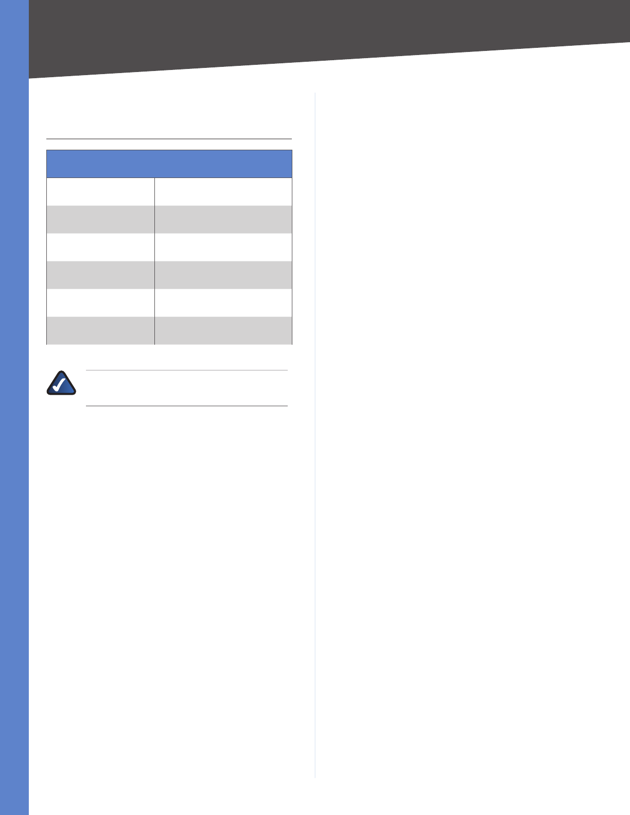
89
Contact Information
WebView Switches
Appendix I
Appendix I:
Contact Information
Linksys Contact Information
Website http://www.linksys.com
Support Site http://www.linksys.com/support
FTP Site ftp.linksys.com
Advice Line 800-546-5797 (LINKSYS)
Support 800-326-7114
RMA (Return Merchandise
Authorization) http://www.linksys.com/warranty
NOTE: Details on warranty and RMA issues can
be found in the Warranty section of this Guide.
8050610A-IN
