_New_LVS_Admin_Guide LVS AG NC 200805
2014-10-28
: Linksys Lvs Ag Nc 200805 LVS_AG_NC_200805 1224639041905 userguide s
Open the PDF directly: View PDF ![]() .
.
Page Count: 246 [warning: Documents this large are best viewed by clicking the View PDF Link!]
- Document Audience
- Firmware
- Document Purpose and Contents
- Document Conventions
- Related Documentation
- Finding Information in PDF Files
- Online Resources
- Copyright and Trademarks
- Technical Support
- Getting Started
- Basic Administration of the SPA9000
- Upgrading Firmware for the SPA9000
- Connecting to the SPA9000 Administration Web Server
- Saving or Discarding Changes SPA9000
- Access Levels
- Setting Passwords for User and Administrator Accounts
- Configuring Basic Settings
- Viewing Information about the SPA9000
- Viewing Information about Client Stations
- Using the Interactive Voice Response Unit
- Configuring the SPA9000 for ITSP Interoperability
- Configuring Phone Lines and Calling Routing Behavior
- Configuring SPA9000 FXS Ports
- Configuring Line Interfaces on the SPA9000
- Configuring Dial Plans
- Managing the Line Selection for Outbound Calls
- Managing Caller ID Settings for Outgoing Calls
- Managing Inbound Calls with the Contact List
- Routing an Inbound Call to the Auto Attendant
- Routing an Inbound Call to a Receptionist or Client Stations
- Example Contact List Rules
- Supporting Multiple DID Numbers Per Line Interface
- An incoming call to the main number is answered by the Auto-Attendant, while calls to the other nine DID numbers are routed to dedicated private extensions.
- Supporting Direct Inward Dialing to Phone Extensions
- Entering a Contact List Rule
- Call Forwarding Support on SPA9000
- Call Transfer Support on SPA9000
- Managing Inbound Calls with Hunt Groups
- Managing Inbound Calls with Shared Line Appearances
- Administering the SPA400 and Voice Mail Service
- Connecting to the SPA400 Administration Web Server
- Configuring the SPA400 Network Connection
- Saving or Discarding Changes on the SPA400
- Managing Access to the SPA400 Web-Based Configuration Utility
- Upgrading the Firmware for the SPA400
- Configuring a SPA400 to Interoperate with the SPA9000
- Configuring a SPA400 for PSTN Access
- Configuring a SPA400 for Voice Mail Service
- Managing the Voice Mail Messages on the USB Key
- Enabling Debugging on the SPA400
- Configuring Music on Hold
- Configuring the LVS Auto-Attendant
- Localization
- Advanced Topics in LVS Administration
- SPA9000 Field Reference
- SPA400 Field Reference
- Warranty Information
- Regulatory Information
- Safety Information
- Software License Agreement
- Contacts
- Acronyms
- Glossary

ADMINISTRATION
GUIDE
Linksys Voice System
SPA9000 IP Telephony System
SPA400 PSTN VoIP Gateway with Integrated Voice Mail Server
SPA9x2 IP Phones

Table of Contents
Linksys Voice System Administration Guide i
Preface . . . . . . . . . . . . . . . . . . . . . . . . . . . . . vi
Document Audience vi
Firmware vii
Document Purpose and Contents viii
Document Conventions ix
Related Documentation ix
Finding Information in PDF Files xi
Finding Text in a PDF xi
Finding Text in Multiple PDF Files xi
Online Resources xiii
Copyright and Trademarks xiii
Technical Support xiii
Chapter 1: Getting Started . . . . . . . . . . . . . . . . . . . 13
Introduction to the Linksys Voice System 13
SPA9000 IP PBX 14
SPA400 SIP-PSTN Gateway and Voicemail Server 14
SPA900 Series IP Phones and Accessories 14
Deployment Scenarios 15
Deploying the LVS with PSTN Access and Local Voice Mail 16
Deploying the LVS with ITSP Service Only 17
Deploying the LVS with ITSP Service, PSTN Access and Local Voice Mail 18
ITSP Service, PSTN and ISDN Access and Local Voice Mail 19
Initial Installation, and Configuration 20
Chapter 2: Basic Administration of the SPA9000 . . . . . . . . . 21
Upgrading Firmware for the SPA9000 21
Connecting to the SPA9000 Administration Web Server 24
Saving or Discarding Changes SPA9000 24
Access Levels 25
Setting Passwords for User and Administrator Accounts 25
Configuring Basic Settings 26
Setting Up the WAN Connection for the SPA9000 26
Setting the Date and Time 27
Configuring Daylight Saving Time 27
SPA9000 Ethernet Port 28
LAN and Application Guidelines 28
Configuring Multicast Addressing and Group Paging 29
Collecting System Logs and Debug Information 31
Viewing Information about the SPA9000 33
Viewing Information about Client Stations 33
Using the Interactive Voice Response Unit 33
Using the IVR Menu 34
Entering a Password through the IVR 37
Chapter 3: Configuring the SPA9000 for ITSP Interoperability . . 39
About LVS and SIP 39
Network Address Translation (NAT) and Voice over IP (VoIP) 40
NAT Mapping with SIP-ALG Router 40
NAT Mapping with Session Border Controller 41

Table of Contents
Linksys Voice System Administration Guide ii
Configuring NAT Mapping with a Static IP Address 41
Configuring NAT Mapping with STUN 42
Firewalls and SIP 43
Configuring SIP Timer Values 44
Chapter 4: Configuring Phone Lines and Calling Routing Behavior 45
Configuring SPA9000 FXS Ports 45
Configuring Line Interfaces on the SPA9000 46
Configuring a Line Interface for ITSP Service 46
Configuring a Line Interface for a SPA400 (PSTN or Voice Mail) 48
Configuring Call Capacity for a Line Interface 51
Configuring Dial Plans 52
How the Dialed Digits are Processed 53
Digit Sequences 53
Digit Sequence Examples 55
Acceptance and Transmission the Dialed Digits 56
Editing the System Dial Plan 57
Entering a Phone Dial Plan 58
Entering the Line Interface Dial Plan 59
Setting the Timers for the Dial Plan 59
Managing the Line Selection for Outbound Calls 63
Line Availability 63
Configuring a Call Routing Rule 63
Entering a Call Routing Rule 65
Managing Caller ID Settings for Outgoing Calls 65
Managing Inbound Calls with the Contact List 66
Routing an Inbound Call to the Auto Attendant 66
Routing an Inbound Call to a Receptionist or Client Stations 66
Example Contact List Rules 66
Supporting Multiple DID Numbers Per Line Interface 68
An incoming call to the main number is answered by the Auto-Attendant, while calls
to the other nine DID numbers are routed to dedicated private extensions. 69
Supporting Direct Inward Dialing to Phone Extensions 69
Entering a Contact List Rule 70
Call Forwarding Support on SPA9000 71
Call Transfer Support on SPA9000 72
Call Forward Bridge Mode 72
Call Transfer Bridge Mode 72
Managing Inbound Calls with Hunt Groups 73
Hunt Group that Rings All Stations Simultaneously 73
Hunt Group that Rings Stations Individually 75
Managing Inbound Calls with Shared Line Appearances 77
About Shared Line Appearances 77
Chapter 5: Administering the SPA400 and Voice Mail Service . . 80
Connecting to the SPA400 Administration Web Server 80
Configuring the SPA400 Network Connection 81
Saving or Discarding Changes on the SPA400 82
Managing Access to the SPA400 Web-Based Configuration Utility 83
Upgrading the Firmware for the SPA400 84

Table of Contents
Linksys Voice System Administration Guide iii
Configuring a SPA400 to Interoperate with the SPA9000 85
Configuring a SPA400 for PSTN Access 87
Configuring a SPA400 for Voice Mail Service 87
Voice Mail Capacity 88
Configuring Local Voice Mail Service on a SPA400 88
Setting Up Voice Mail on Each Station 90
Enabling Remote Voice Mail Access (Optional) 93
Managing the Voice Mail Messages on the USB Key 94
Enabling Debugging on the SPA400 95
Chapter 6: Configuring Music on Hold . . . . . . . . . . . . . . 97
Using the Internal Music Source for Music On Hold 97
Using the Internal Music Source 97
Changing the Music File for the Internal Music Source 98
Restoring the Original Music File 98
Configuring a Streaming Audio Server 99
Using a Streaming Audio Server 99
Using the IVR with an SAS Line 100
Example SAS with MOH 100
Configuring the Streaming Audio Server 101
Chapter 7: Configuring the LVS Auto-Attendant . . . . . . . . 103
How the Auto Attendant Works 103
Working with the Auto Attendant Greetings 104
Using Pre-Recorded Prompts 104
Recording an Auto Attendant Prompt 105
Downloading Prompts 107
Writing an Auto Attendant Script 108
An Introduction to XML Scripting Grammar in AA Script Examples 109
Elements of XML Scripting Grammar 111
Auto Attendant XML Instructions Set 113
Entering an Auto Attendant Script 115
Configuring the DayTime, NightTime and Weekend/Holiday Auto Attendants 116
Configuring Dial Plans for the Auto Attendant 117
Chapter 8: Localization . . . . . . . . . . . . . . . . . . . . 118
Requirements for Localization 118
Localizing the SPA9000 Auto Attendant Prompts 118
Local Time Configuration 120
Configuring the SPA9000 and SPA9xx Call Progress Tones 120
Localizing the SPA400 Voice Mail Prompts 125
Localizing the SPA400 Call Disconnect Tones 126
Localizing the SPA400 Caller ID Method 128
Appendix A: Advanced Topics in LVS Administration . . . . . . . . 130
Technology Background 130
Session Initiation Protocol 130
SPA9000 Media Proxy 132
Using the SPA9000 with a Firewall or Router 133
SPA400 SIP-PSTN Gateway 133

Table of Contents
Linksys Voice System Administration Guide iv
SPA9000 Architecture 134
SIP-NAT Interoperation 135
Determining Whether the Router Uses Symmetric or Asymmetric NAT 136
Advanced Call Control and Routing 137
Configuring Vertical (Supplementary) Service Codes 137
Managing the Outbound Call Routing Groups 139
Configuring Outbound Call Codec Selection Codes 141
Advanced Topics for SPA400 Voice Mail Service 141
How Voicemail Works 142
Checking Voicemail from an External Number 142
Depositing Voicemail 143
Subscribing to Voicemail Notification 144
Remote Provisioning Features 145
Using Configuration Profiles 145
Client Auto-Configuration 146
Manual Client Configuration 147
Client Registration 149
Using the Upgrade URL 150
Using the Resync URL 151
Using the Reboot URL 151
Appendix B: SPA9000 Field Reference . . . . . . . . . . . . . . . 152
Router Tab 152
Status page 152
Wan Setup page 153
Lan Setup page and Application page 156
Voice tab 156
Info page 156
System page 159
SIP Page 160
Provisioning page 176
Regional page 176
FXS 1/2 page 189
Line 1/2/3/4 page 196
Appendix C: SPA400 Field Reference . . . . . . . . . . . . . . . . 203
Setup 203
Basic Setup 203
SPA9000 Interface 204
Voice 205
Voicemail Server 208
Voicemail Users 209
Administration 209
Management 209
Factory Default 210
USB Setting 210
Firmware Upgrade 210
Reboot 210
Status 211
Gateway 211
Event Logs 212

Table of Contents
Linksys Voice System Administration Guide v
Set Log Level 212
Tone 212
Appendix D: Warranty Information . . . . . . . . . . . . . . . . 214
Limited Warranty 214
Exclusions and Limitations 214
Obtaining Warranty Service 215
Technical Support 215
Appendix E: Regulatory Information . . . . . . . . . . . . . . . . 216
Federal Communications Commission Interference Statement 216
Industry Canada Statement 216
Règlement d’Industry Canada 216
EC Declaration of Conformity (Europe) 217
User Information for Consumer Products Covered by EU Directive 2002/96/EC on Waste
Electric and Electronic Equipment (WEEE) 217
Appendix F: Safety Information . . . . . . . . . . . . . . . . . . 224
Meaning of the Warning Symbol 224
General Safety Information 224
Power Safety Information 225
Appendix G: Software License Agreement . . . . . . . . . . . . . 227
Software in Linksys Products: 227
Software Licenses: 227
Schedule 1 Linksys Software License Agreement 227
Schedule 2 229
Schedule 3 234
Appendix H: Contacts . . . . . . . . . . . . . . . . . . . . . . . 237
Appendix I: Acronyms . . . . . . . . . . . . . . . . . . . . . . . 238
Appendix J: Glossary . . . . . . . . . . . . . . . . . . . . . . . . 241

Linksys Voice System Administration Guide vi
Document Audience
Preface
The Linksys Voice System Administration Guide is intended to help VARs and Service Providers to
manage and configure the Linksys Voice System (LVS). This preface provides helpful
information about this guide and other resources that are available to you. Before you begin to
use this guide, refer to the following topics:
•”Document Audience,” on page vi
•”Document Purpose and Contents,” on page viii
•”Document Conventions,” on page ix
•”Related Documentation,” on page ix
•”Finding Information in PDF Files,” on page xi
•”Online Resources,” on page xiii
•”Copyright and Trademarks,” on page xiii
Document Audience
This document is written for the following audience:
• Service providers offering services using LVS products
• VARs and resellers who need LVS configuration references
• System administrators or anyone who performs LVS installation and administration
Note This guide does not provide the configuration information required by
specific service providers. Please consult with the service provider for
specific service parameters.
Linksys Voice System Administration Guide vii
Firmware
Firmware
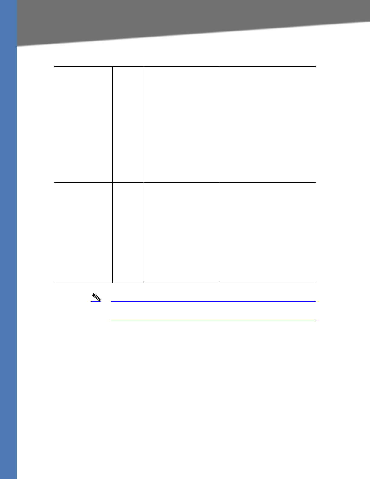
This guide supports the following firmware releases. The installed firmware must be at least the
indicated in the table below.
Product Firmware Version
SPA9000 5.1.9
SPA400 1.0.1.4
SPA922/SPA942 5.2.5
SPA962 5.2.8
SPA901 5.1.5
SPA921/SPA941 5.1.8

Linksys Voice System Administration Guide viii
Document Purpose and Contents
Document Purpose and Contents
This document provides information that an administrator needs to configure the Linksys Voice
System, which typically consists of a SPA9000 IP PBX, one or more SPA900 Series IP phones, and
the optional SPA400 PSTN gateway and voice mail server. This guide focuses primarily on the
tasks that an administrator performs to configure a SPA9000 with the SPA9000 administration
web server.
NOTE: This guide does not cover initial installation and configuration, SPA900 Series phone
configuration, the Setup Wizard, or provisioning. See ”Related Documentation,” on page ix.
The information in this guide is organized into the following chapters and appendices:
Chapter 1, "Getting Started." This chapter introduces you to the Linksys Voice System
(LVS) by describing the components and presenting
several deployment scenarios.
Chapter 2, "Basic
Administration of the SPA9000."
This chapter introduces you to basic administrative tasks
using the SPA9000 administration web server and the
Interactive Voice Response Unit.
Chapter 3, "Configuring the
SPA9000 for ITSP
Interoperability"
This chapter provides configuration details for the
purpose of helping you to ensure that your infrastructure
properly supports the LVS.
Chapter 4, "Configuring Phone
Lines and Calling Routing
Behavior"
This chapter describes many features that you can
configure on the SPA9000 to ensure smooth handling of
all inbound and outbound calls, and ease of use.
Chapter 5, "Administering the
SPA400 and Voice Mail Service"
This chapter guides you through the process of
configuring and managing the SPA400 for PSTN access
and voice mail service.
Chapter 6, "Configuring Music
on Hold"
This chapter explains how to configure Music on Hold
using either a music file or streaming audio.
Chapter 7, "Configuring the LVS
Auto-Attendant"
This chapter describes how to configure the LVS Auto
Attendant using the IVR, and XML scripting.
Chapter 8, "Localization" You can localize your LVS with the language files, tones,
and ring patterns that are appropriate for your region.
Appendix A, "Advanced Topics
in LVS Administration"
This appendix provides technical information that is
useful to individuals who want a better understanding of
how the LVS works.
Appendix B, "SPA9000 Field
Reference"
This appendix describes the fields on each page of the
SPA9000 administration web server.
Appendix C, "SPA400 Field
Reference"
This appendix describes the fields on each page of thes of
the SPA400 administration web server.
Linksys Voice System Administration Guide ix
Document Conventions
Document Conventions
The following are the typographic conventions used in this document.
Related Documentation
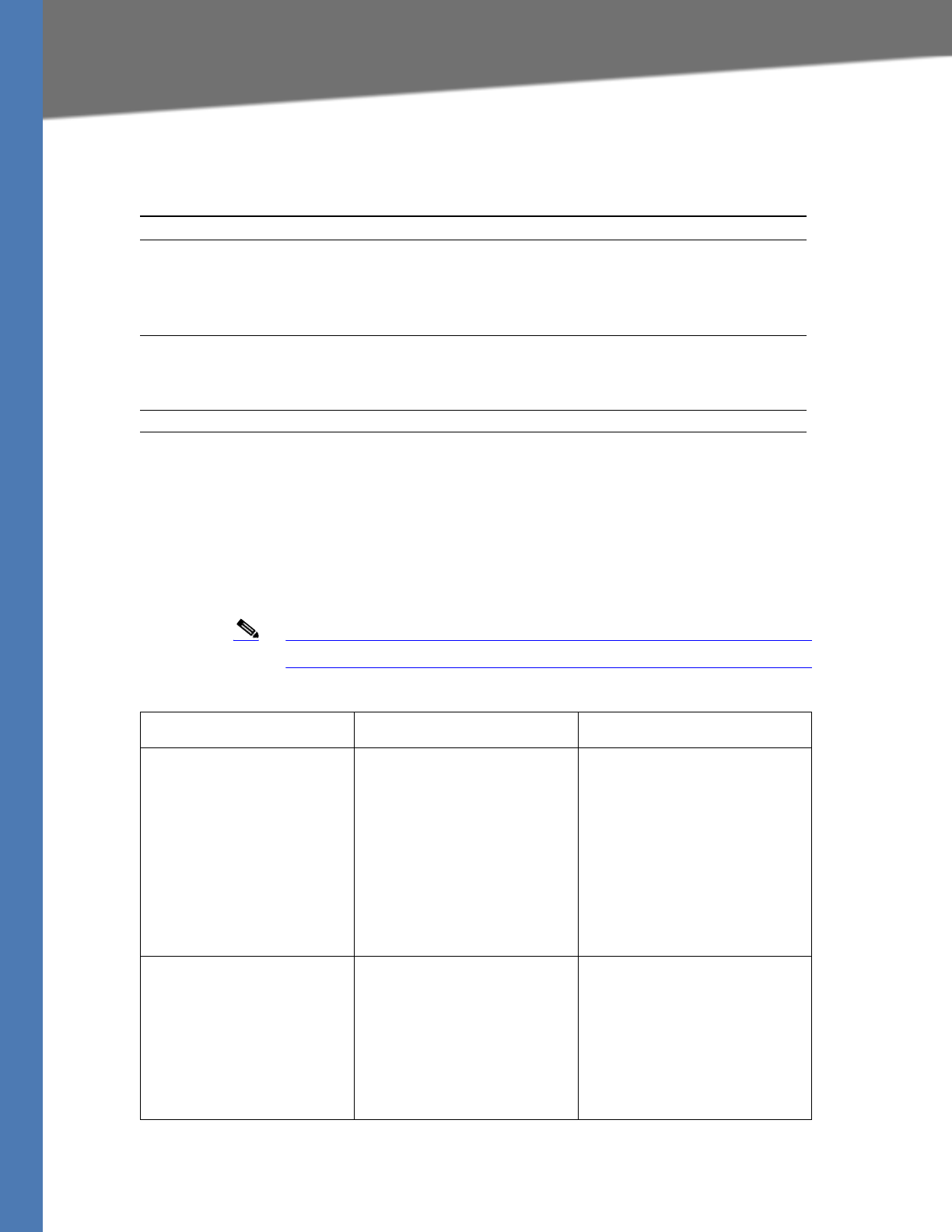
This LVS Administration Guide is part of a complete suite of documentation that is available to
assist you in using and configuring Linksys devices. The following documents are of special
interest to LVS administrators.
Note These documents and more are available at Linksys.com.
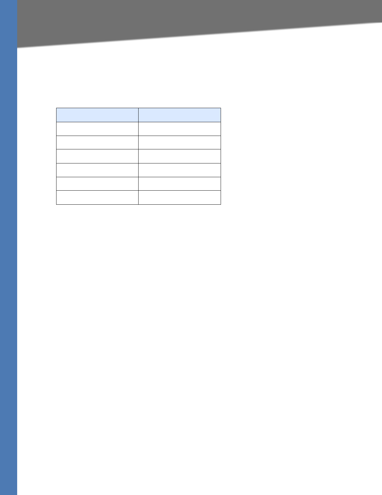
Typographic Element Meaning
Boldface May indicate either of the following:
• A user interface element that you need to click, select, or
otherwise act on
• A literal value to be entered in a field.
Italic May indicate either of the following:
• A variable that should be replaced with a literal value.
• The name of a page, section, or field in the user interface
Monospaced Font Indicates code samples or system output.
Document Title Description Intended Audience
Linksys Voice System
Installation and
Configuration Guide
•Network design
considerations and site
preparation
• Switch configuration
• Initial installation and
configuration of the LVS
components
• SPA9000, SPA400,
SPA900 series IP phones
VARs and Service Providers
Linksys Phone
Administration Guide
•Configuration and
management of IP
phones
• Deployment options
with or without the
SPA9000 IP PBX
• SPA9x2 series IP phones
VARs and Service Providers

Linksys Voice System Administration Guide x
Related Documentation
Linksys SPA9x2 Phone User
Guide
• Phone setup
• Phone features
• SPA9x2 series IP phones
VARS and phone end-users
Linksys Analog Telephone
Adapter Administration
Guide
• Administration and use
of Linksys ATAs
• PAP2T, SPA2102,
SPA3102, SPA8000,
AG310, RTP300, WRP400,
and WRTP54G
VARS, system administrators,
and Service Providers
Linksys Provisioning Guide • Provisioning LVS
components
Service Providers only
SPA9000 FAQS Specifica-
tion, Troubleshooting,Con-
figuration, and General
Specifications
Answers to Frequently Asked
Questions, within the Easy
Answers Knowledge Base at
www.linksys.com/kb
VARs and Service Providers
Document Title Description Intended Audience
Linksys Voice System Administration Guide xi
Finding Information in PDF Files
Finding Information in PDF Files
The PDF Find/Search tool lets you find information quickly and easily online. You can:
• Search an individual PDF.
• Search multiple PDFs at once (for example, all PDFs in a specific folder or disk drive).
• Perform advanced searches.
Finding Text in a PDF
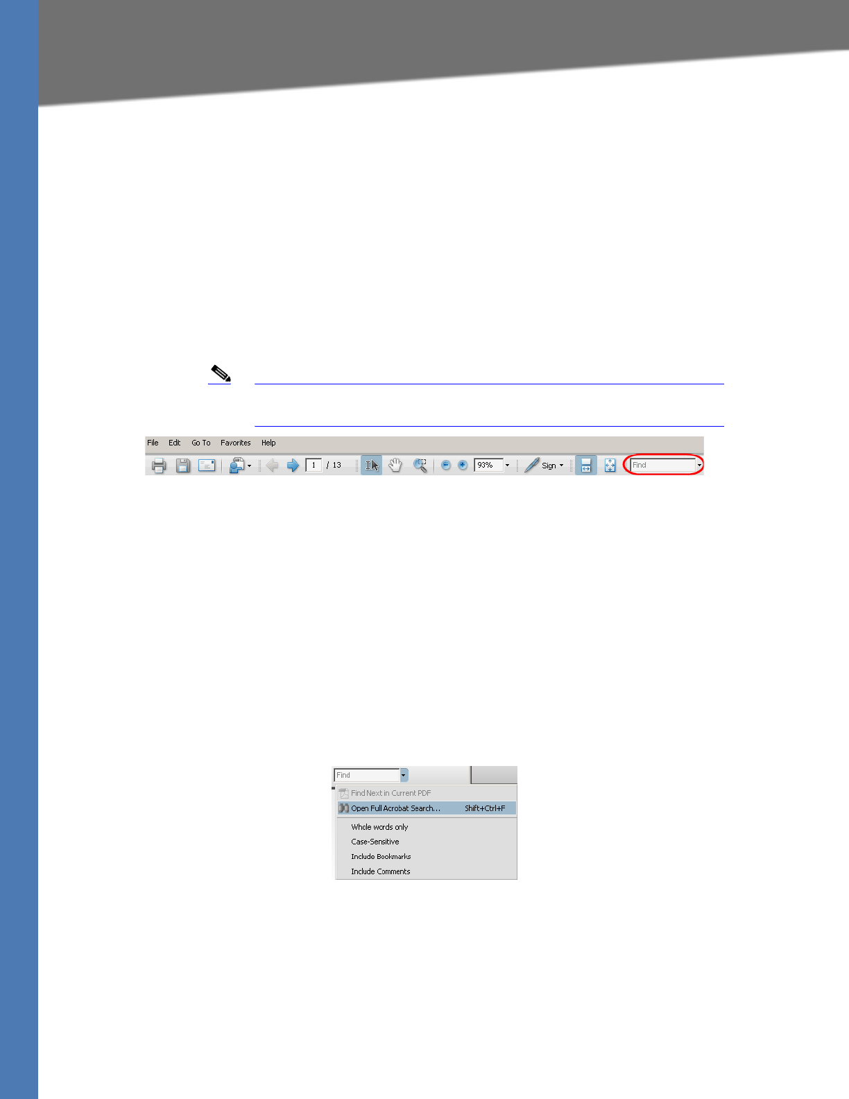
1. Enter your search terms in the Find box on the toolbar.
Note By default, the Find tool is available at the right end of the Acrobat
toolbar. If the Find tool does not appear, choose Edit > Find.
2. Optionally, click the arrow next to the Find text box to refine your search by choosing
special options such as Whole words only.
3. Press Enter. Acrobat displays the first instance of the search term. Press Enter again to
continue to more instances of the term.
Finding Text in Multiple PDF Files
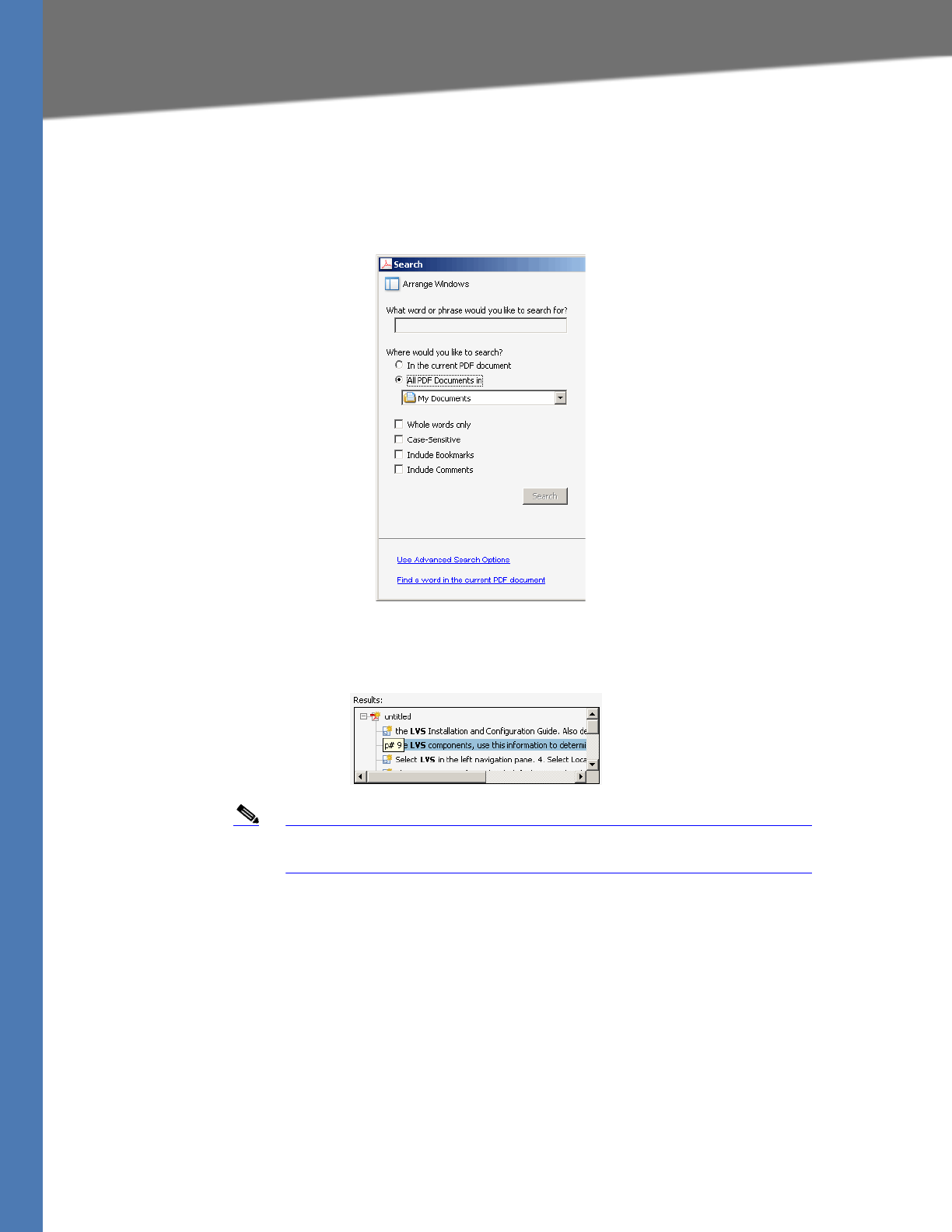
The Search window lets you search for terms in multiple PDF files that are stored on your PC or
local network. The PDF files do not need to be open.
1. Start Acrobat Professional or Adobe Reader.
2. Choose Edit > Search, or click the arrow next to the Find box and then choose Open Full
Acrobat Search.
3. In the Search window, complete the following steps:
a. Enter the text that you want to find.
b. Choose All PDF Documents in.
c. From the drop-down box, choose Browse for Location. Then choose the location on
your computer or local network, and click OK.
Linksys Voice System Administration Guide xii
Finding Information in PDF Files
d. If you want to specify additional search criteria, click Use Advanced Search Options,
and choose the options you want.
e. Click Search.
4. When the Results appear, click + to open a folder, and then click any link to open the file
where the search terms appear.
Note For more information about the Find and Search functions, see the
Adobe Acrobat online help.
Linksys Voice System Administration Guide xiii
Online Resources
Online Resources
Website addresses in this document are listed without http:// in front of the address because
most current web browsers do not require it. If you use an older web browser, you may have to
add http:// in front of the web address.
Copyright and Trademarks
Technical Support
A list of technical support phone numbers and websites is available in Appendix H, "Contacts."
Resource Link
Linksys www.linksys.com
Linksys International www.linksys.com/international
Glossary www.linksys.com/glossary
Network Security www.linksys.com/security
Linksys is a registered trademark or trademark of
Cisco Systems, Inc. and/or its affiliates in the U.S.
and certain other countries. Copyright © 2008
Cisco Systems, Inc. All rights reserved. Other
brands and product names are trademarks or
registered trademarks of their respective
holders.
Linksys Voice System Administration Guide 13
1Introduction to the Linksys Voice System
Getting Started
Getting Started
This chapter introduces you to the Linksys Voice System (LVS) by describing the components
and presenting several deployment scenarios.
• ”Introduction to the Linksys Voice System,” on page 13
•”Deployment Scenarios,” on page 15
•”Initial Installation, and Configuration,” on page 20
Introduction to the Linksys Voice System
The LVS is an affordable and feature-rich voice over IP (VoIP) telephone system that is designed
especially for small businesses. The LVS uses standard TCP/IP protocols and can provide global
connectivity through any Internet Telephony Service Provider (ITSP) that supports Session
Initiation Protocol (SIP).
At minimum, the LVS includes a SPA9000 IP PBX and one or more SPA900 series IP phones.
These devices are connected through a switch to a local area network. With an Internet
connection, the LVS can subscribe to ITSP services to take advantage of low calling rates. With
the optional SPA400, the LVS can connect to the Public Switched Telephone Network (PSTN) to
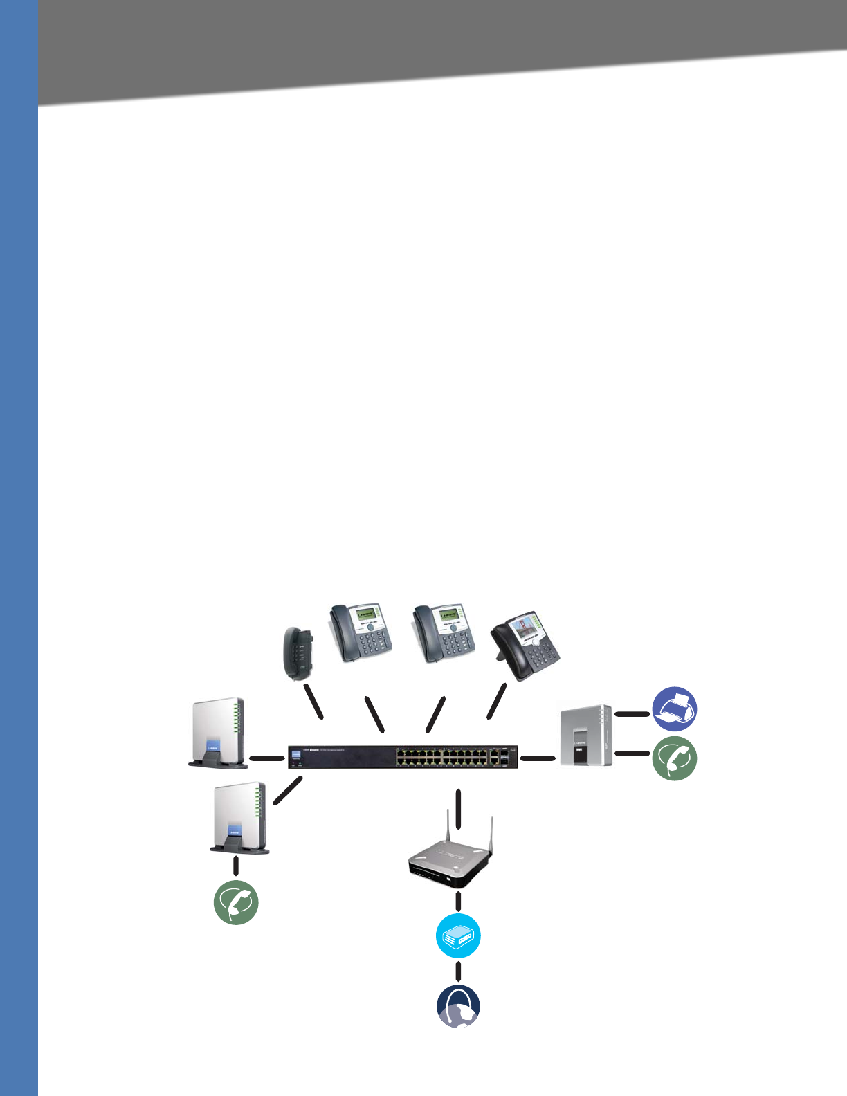
support legacy phone lines. Figure 1-1 illustrates the LVS Solution in a typical deployment.
Figure 1-1 The Linksys Voice System (LVS) with the SPA9000 and SPA400
SPA9xx IP Phones
SLM224P Switch SPA9000 IP PBX
WRV200 Router
Internet
Integrated
Access Device
Analog
Phone Lines
SPA400
for Voice Mail
SPA400
for PSTN Access
Analog Phones
or Fax Machines
Linksys Voice System Administration Guide 14
Introduction to the Linksys Voice System
Getting Started
SPA9000 IP PBX
The SPA9000 is an IP PBX that supports up to 16 phones. It also has a built-in Analog Telephone
Adapter (ATA) with two FXS ports for analog telephones, fax devices, or an external music
source for the music on-hold service. Devices connected to the FXS ports are not included in
the licence's device count.
The SPA9000 has four line interfaces, which can be configured in any combination for ITSP
service, ISDN access, SPA400 PSTN access, or SPA400 voice mail service. A different ITSP account
can be configured on each line interface. If a service provider supplies a group of sequential
direct inward dial (DID) phone numbers (such as 408-555-0100 through 555-0145) the SPA9000
can support all of the assigned numbers on a single line interface.
The SPA9000 includes an Auto Attendant service that plays pre-recorded voice messages to
offer the caller a menu of choices and to direct the call. When the Auto-Attendant is enabled, it
parses and operates on user input (key presses that produce DTMF tones) following the rules
specified in the Auto Attendant script on the SPA9000.
SPA400 SIP-PSTN Gateway and Voicemail Server
The SPA400 provides a SIP-PSTN gateway for voice connectivity between the PSTN and the
local client stations that are connected to the SPA9000. It also includes an integrated voice mail
application that supports up to 32 voice mail accounts with customized greetings, providing
LVS users the ability to receive and playback voice mail messages.
Each SPA400 occupies one of the four line interfaces on the SPA9000. The SPA400 has four ports
for that can be connected to PSTN or ISDN lines.
SPA900 Series IP Phones and Accessories
Linksys provides a variety of IP phones to meet the needs of small businesses. Table 1-1
provides a comparison of the available models.
NOTE: This guide explains how to configure the SPA9000 and the SPA400 to support the calling
features on the phones. For more information about the phones, see the Linksys Phone
Administration Guide and the Linksys SPA9x2 Phone User Guide.
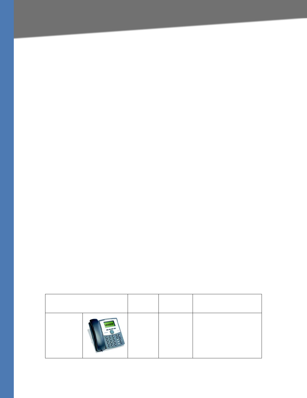
Table 1-1 Linksys SP900 Series IP Phones and Accessories
Product RJ-45 Voice Lines Additional Features/
Notes
SPA922* 2 1 One-line IP phone with
Power over Ethernet (PoE)
support
Linksys Voice System Administration Guide 15
Deployment Scenarios
Getting Started
* NOTE: SPA922, SPA942, SPA962 do not include an external power adapter as they support
Power over Ethernet (802.3af). If the phones are connected to a non-POE switch, the PA100
power adapter is required.
Deployment Scenarios
The LVS can meet the calling needs of many small businesses. Various deployment scenarios
are possible. This section includes the following examples:
•”Deploying the LVS with PSTN Access and Local Voice Mail,” on page 16
•”Deploying the LVS with ITSP Service Only,” on page 17
•”Deploying the LVS with ITSP Service, PSTN Access and Local Voice Mail,” on page 18
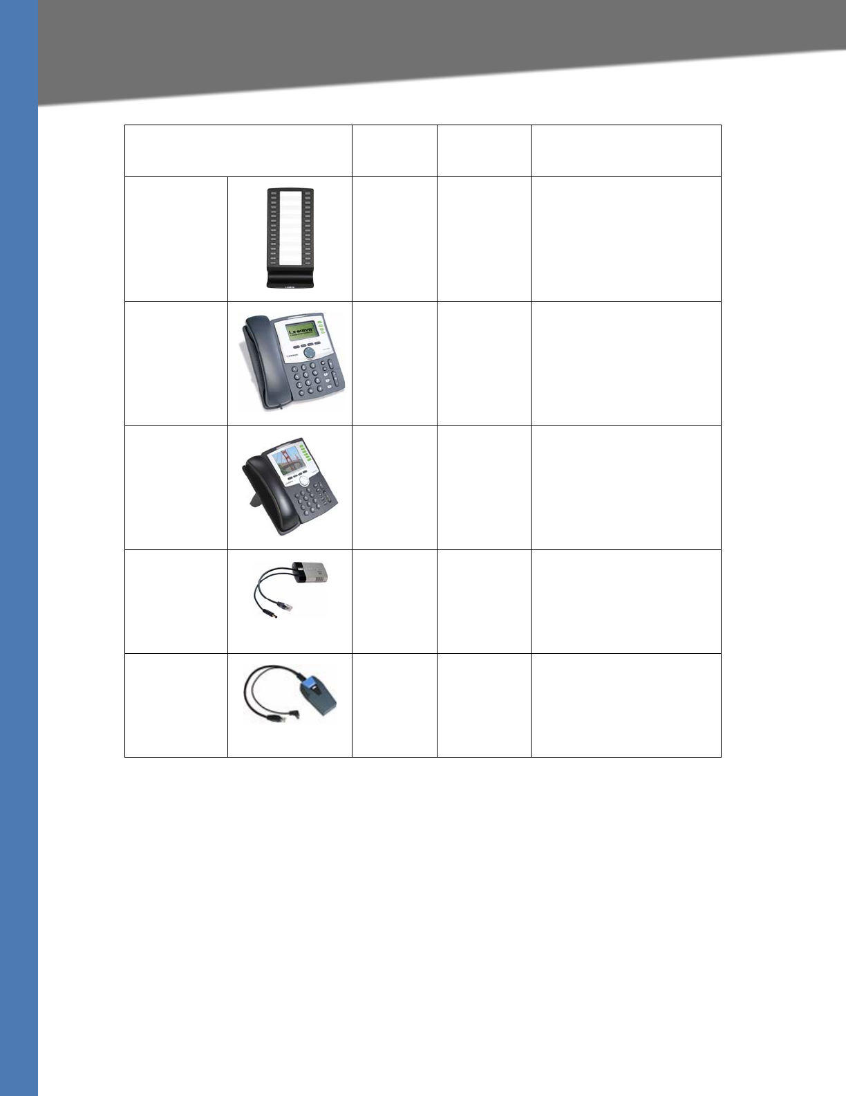
SPA932 — — Attendant console (sidecar)
for SPA962 with 32 buttons
and LEDs for monitoring
and call transfer
SPA942* 2 4 Four-line IP phone with
Power over Ethernet (PoE)
support
SPA962* 2 6 Six-line IP Phone with high-
resolution color display
and Power over Ethernet
(PoE) support
POES5 1 N/A Provides an 802.3af PoE
port for connection back to
a PoE switch for SPA9000,
SPA400 and SPA9x1
phones
WBP54G 1 N/A Converts your IP phone
into a wireless device, so it
can connect to your
wireless network without
an Ethernet cable
Product RJ-45 Voice Lines Additional Features/
Notes

Linksys Voice System Administration Guide 16
Deployment Scenarios
Getting Started
•”ITSP Service, PSTN and ISDN Access and Local Voice Mail,” on page 19
Deploying the LVS with PSTN Access and Local Voice Mail
In this scenario, the customer requires a robust phone system but is not using VoIP services. The
LVS is deployed with a SPA9000 IP PBX, one SPA400 for PSTN access with four FXO ports, and
another SPA400 for local voice mail service. Optionally, analog phones or fax machines (not
illustrated) can be connected to the two phone ports on the SPA9000.
SPA9xx IP Phones
SLM224P Switch SPA9000 IP PBX
Analog
Phone Lines
SPA400
for Voice Mail
SPA400
for PSTN Access
Linksys Voice System Administration Guide 17
Deployment Scenarios
Getting Started
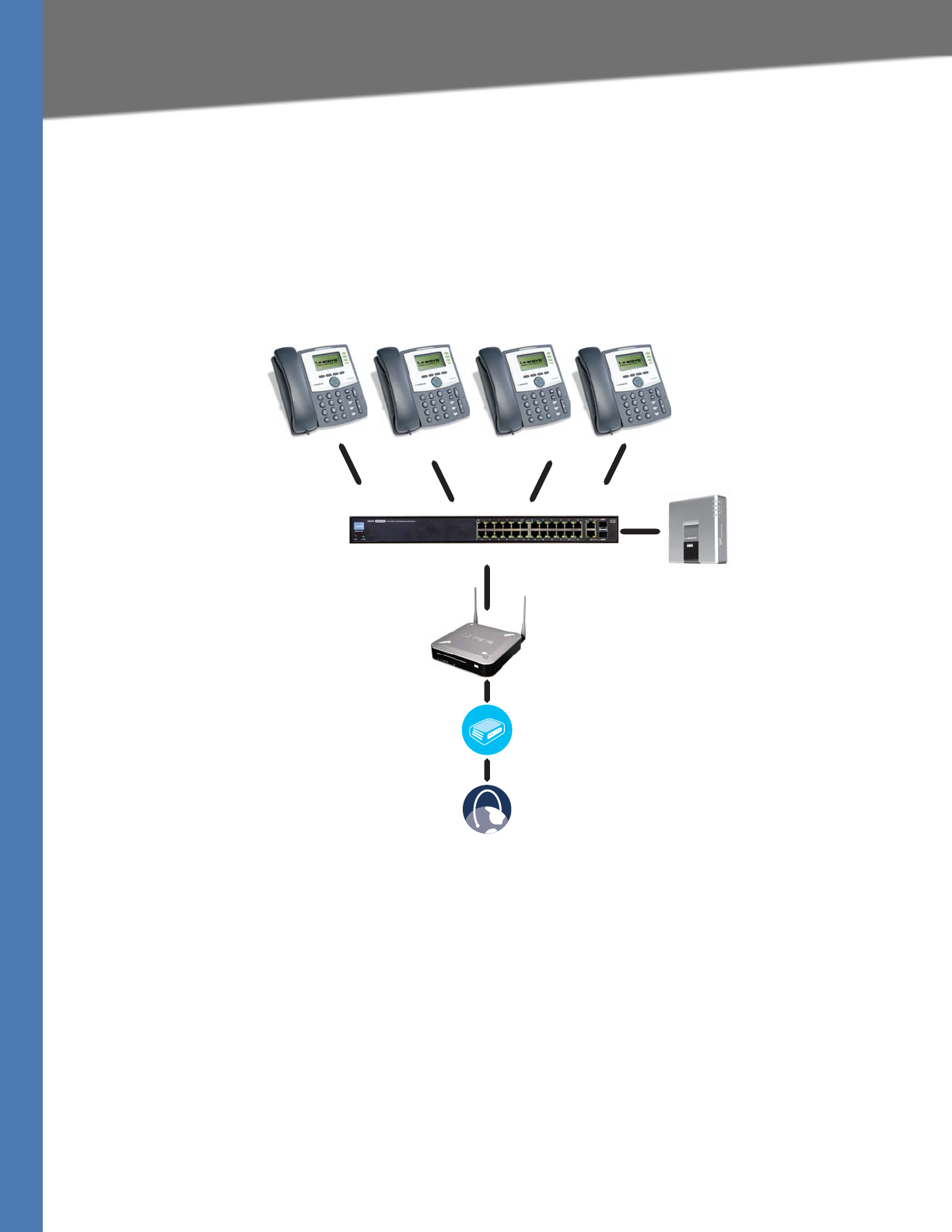
Deploying the LVS with ITSP Service Only
In this scenario, a customer has no legacy telephone numbers and does not require local voice
mail (either needs no voice mail at all or has voice mail hosted by the ITSP). The LVS is deployed
with the SPA9000 IP PBX, VoIP service, and four SPA9x2 series phones. Four phones are
connected at this time, but the LVS can be expanded to include 16 SPA9xx IP phones.
Optionally, analog phones or fax machines (not illustrated) can be connected to the two phone
ports on the SPA9000.
SPA9xx IP Phones
SLM224P Switch
SPA9000 IP PBX
WRV200 Router
Internet
Integrated
Access Device
Linksys Voice System Administration Guide 18
Deployment Scenarios
Getting Started
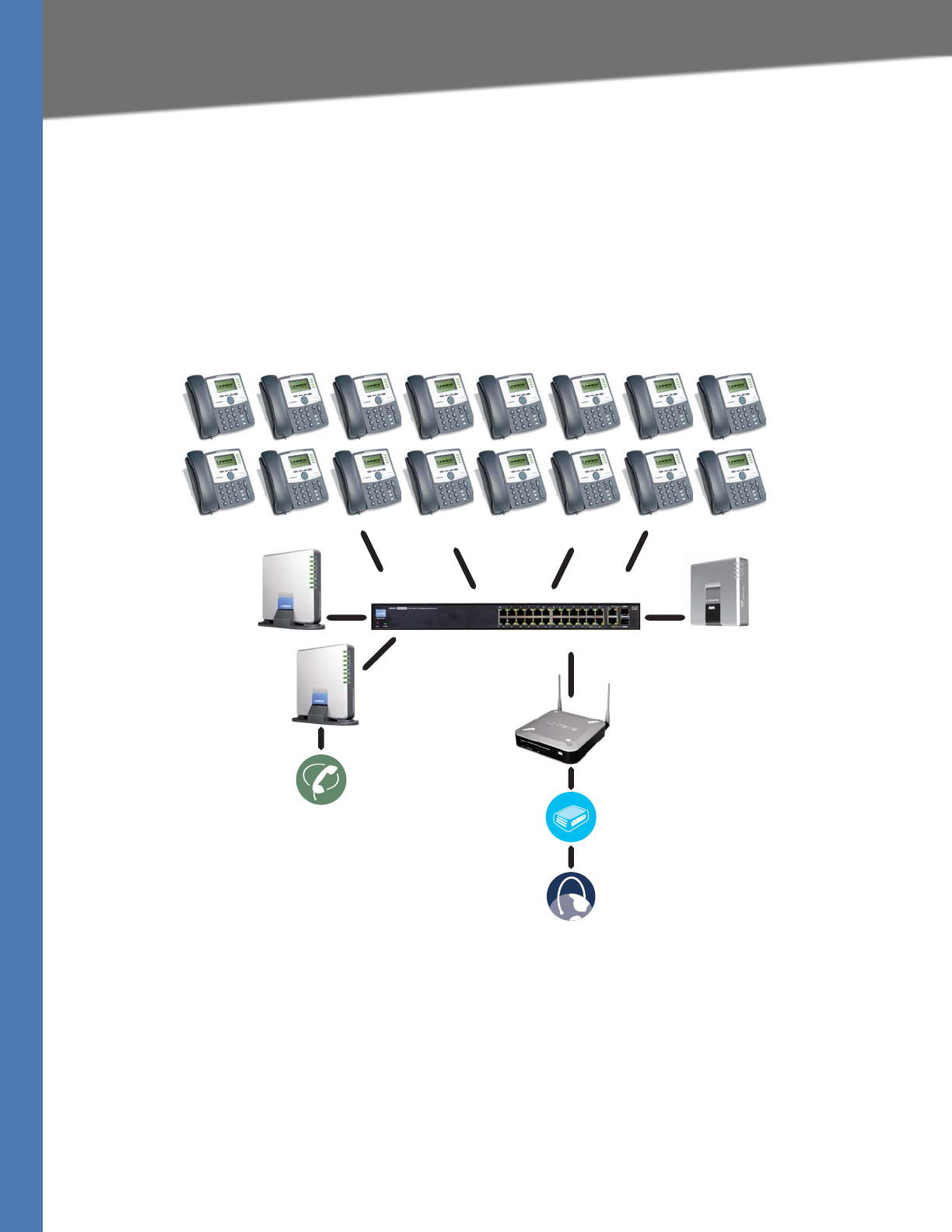
Deploying the LVS with ITSP Service, PSTN Access and Local Voice Mail
In this scenario, the customer wants to use ITSP service for reduced long distance fees but
needs to support legacy local telephone numbers (for example, to receive calls over the
original legacy telephone number, or to route local telephone calls). This customer also prefers
local voice mail service. The LVS is deployed with the SPA9000 IP PBX, VoIP service, one SPA400
unit for voice mail service, another SPA400 units for PSTN access with four FXO ports, and up to
16 SPA900 series phones. Optionally, analog phones or fax machines (not illustrated) can be
connected to the two phone ports on the SPA9000.
SPA9xx IP Phones
SLM224P Switch SPA9000 IP PBX
WRV200 Router
Internet
Integrated
Access Device
Analog
Phone Lines
SPA400
for Voice Mail
SPA400
for PSTN Access
Linksys Voice System Administration Guide 19
Deployment Scenarios
Getting Started
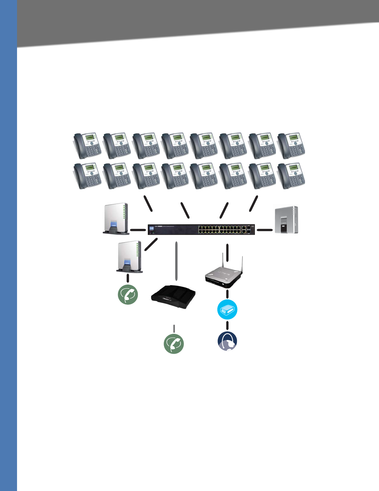
ITSP Service, PSTN and ISDN Access and Local Voice Mail
In this scenario, the customer takes full advantage of the LVS solution, with the SPA9000 IP PBX,
VoIP service, one SPA400 unit for voice mail service, another SPA400 for PSTN access with four
FXO ports, one ISDN Gateway for ISDN BRI access with four BRI ports, and up to 16 SPA9xx IP
phones. Optionally, analog phones or fax machines (not illustrated) can be connected to the
two phone ports on the SPA9000.
SPA9xx IP Phones
SLM224P Switch SPA9000 IP PBX
WRV200 Router
Internet
Integrated
Access Device
Analog
Phone Lines
SPA400
for Voice Mail
SPA400
for PSTN Access
Mediatrix® 4402
BRI Gateway
ISDN
Phone Lines

Linksys Voice System Administration Guide 20
Initial Installation, and Configuration
Getting Started
Initial Installation, and Configuration
Linksys strongly recommends that you use the Linksys Voice System Installation and
Configuration Guide to design your system, to prepare the site, to connect and configure your
equipment, and to set up the essential calling features. By following the instructions in the
installation guide, you can get your system running in less time and with the settings that help
to ensure strong performance.
After you complete the procedures in the installation guide, the users can make and receive
calls. When the optional SPA400 is installed, the users also can record and retrieve voice mail
messages. The SPA9000 has a fully functional Auto Attendant to greet callers, and a default dial
plan that is suitable for most dialing scenarios. You can use this administration guide to refine
the settings, to configure advanced features, and to manage the system.
NOTE: Because the Linksys Voice System Installation and Configuration Guide provides all of the
procedures that you need for initial installation and configuration, those instructions are not
duplicated in this administration guide.

Linksys Voice System Administration Guide 21
2Upgrading Firmware for the SPA9000
Basic Administration of the SPA9000
Basic Administration of the SPA9000
This chapter introduces you to basic administrative tasks using the SPA9000 administration
web server and the Interactive Voice Response Unit.
For Installation and Configuration of LVS in the most common deployment scenarios, refer to
the Linksys Voice System Installation and Configuration Guide, which is available at Linksys.com.
See the following topics:
•”Upgrading Firmware for the SPA9000,” on page 21
•”Connecting to the SPA9000 Administration Web Server,” on page 24
•”Saving or Discarding Changes SPA9000,” on page 24
•”Access Levels,” on page 25
•”Setting Passwords for User and Administrator Accounts,” on page 25
•”Configuring Basic Settings,” on page 26
•”Viewing Information about the SPA9000,” on page 33
•”Viewing Information about Client Stations,” on page 33
•”Using the Interactive Voice Response Unit,” on page 33
Upgrading Firmware for the SPA9000
As needed, you can download new firmware from Linksys.com and then install the firmware on
the SPA9000.
1. Download the firmware from Linksys.com by completing the following steps:
a. Start a web browser and enter the following address: www.linksys.com.
b. On the menu at the top of the page, choose Support > Technical Support.
c. Click Choose a Product.
d. From the Voice over IP (VoIP) drop-down list, choose IP PBX.
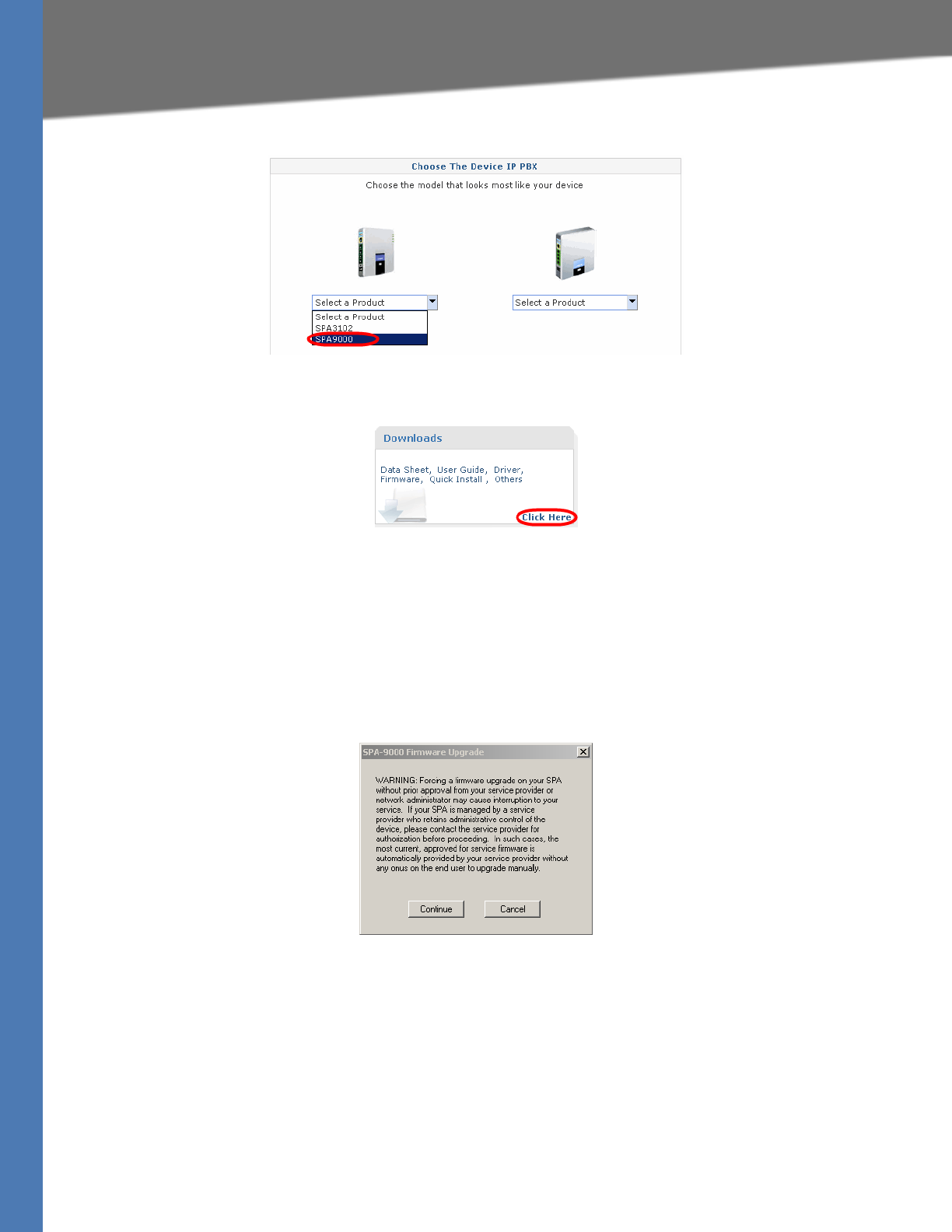
e. On the Choose the Device IP PBX page, choose SPA9000 from the drop-down list on the
left side of the page.
Linksys Voice System Administration Guide 22
Upgrading Firmware for the SPA9000
Basic Administration of the SPA9000
f. On the Technical Support page, click the link in the Downloads section.
g. On the SPA9000 Downloads page, choose the version from the Please select a version
drop-down list.
h. In the Firmware section, click the link for the version that you want to install, and then
save the file on the administration computer.
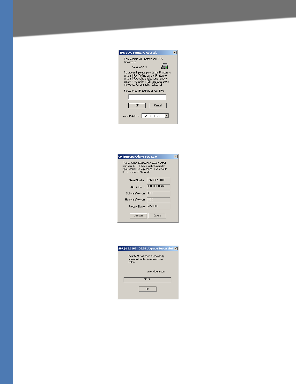
2. Extract the Zip file, and then run the executable file to upgrade the firmware. When the
Firmware Upgrade Warning window appears, click Continue.
3. In the next window that appears, enter the IP address of the SPA9000, and then click OK.
Linksys Voice System Administration Guide 23
Upgrading Firmware for the SPA9000
Basic Administration of the SPA9000
4. In the Confirm Upgrade window, verify that the correct device information and product
number appear. Then click Upgrade.
5. When the confirmation message appears, click OK.
6. To verify the upgrade, complete the following steps:

Linksys Voice System Administration Guide 24
Connecting to the SPA9000 Administration Web Server
Basic Administration of the SPA9000
a. Connect to the SPA9000 administration web server, and choose Admin access with
Advanced settings. (See ”Connecting to the SPA9000 Administration Web Server,” on
page 24).
b. Review the Router > Status page. The Software Version field should show the firmware
version that you installed.
NOTE: You may need to refresh your browser to display the updated page reflecting the
new version number.
Connecting to the SPA9000 Administration Web Server
To connect to the SPA9000 administration web server, perform the following steps.
1. Start Internet Explorer on any computer that is connected to the same network as the
SPA9000.
NOTE: You should have previously connected and configured the SPA9000 as described in
the LVS Installation Guide.
2. Enter the IP address of the SPA9000.
NOTE: You can find the IP address of the SPA9000 by connecting an analog telephone to
the Phone 1 or Phone 2 port on the SPA9000. Then lift the receiver of the phone and press
**** on the keypad to access the IVR menu. Press 110# to hear the IP address.
3. To view administrative features, click Admin Login and then click Advanced.
NOTE: By default, no password is required. For more information, see ”Setting Passwords for
User and Administrator Accounts,” on page 25.
ALTERNATIVELY: After starting Internet Explorer, enter: <SPA9000_ipaddress>/admin/
advanced
Saving or Discarding Changes SPA9000
Changes can be saved or discarded at any time.
• Changes are submitted only when you click the Submit All Changes button at the bottom
of a page. When changes are saved, the SPA9000 may reboot, depending on the type of
changes.
• To discard unsubmitted changes, click the Undo All Changes button at the bottom of the
page.
• Unsubmitted changes are retained when you move among the pages within the Voice
module or the Router module. This feature allows you to make changes on various pages
within a module before clicking Submit All Changes.
• Unsubmitted changes are discarded when you switch between the Router and Voice tabs,
between the User and Administrator accounts, or between the Basic and Advanced views.

Linksys Voice System Administration Guide 25
Access Levels
Basic Administration of the SPA9000
Access Levels
You can use the SPA9000 administration web server to configure and manage your system.
Three levels of access are available:
•User Level: The User account only has the privilege to access part of the web profile
parameters.
•Administrator Level: The Administrator account has the privilege to modify all the web
profile parameters and can also modify the passwords of both Administrator and User
account.
•Advanced: Administrators and Users can view advanced features by clicking the
Advanced link in the top right corner or lower left corner of the menu bar.
By default, no passwords are assigned for either the Administrator account or the User account.
If the password has been set for the Administrator account, the browser prompts for
authentication.
You can switch from User access to Administrator access by clicking the Admin Login link.
Likewise, you can switch from Administrator access to User access by clicking the User Login
link. If a password is set, you will be prompted to enter the password after you click the link.
Setting Passwords for User and Administrator Accounts
The Administrator account name for the SPA9000 is admin (with a lower-case a) and the User
account name is user. These account names cannot be changed.
Note The system prompts for an Administrator account password only if a
password has been set. By default, there is no password. You should set
a password to protect your SPA9000 from unauthorized access.
TIP: Before you make changes, it is recommended
that you save a copy of your current working
configuration:
1. In Internet Explorer, connect to the
administration web server.
2. From the menu, choose File > Save As.
3. Save the configuration as Web Page Complete.
You can use the saved file to review the saved
settings in all pages of the administrative GUI.
NOTE: To save a Telephone Configuration, first
enter the IP address for the configuration, and
then follow the above procedure.

Linksys Voice System Administration Guide 26
Configuring Basic Settings
Basic Administration of the SPA9000
1. Connect to the SPA9000 administration web server, and choose Admin access with
Advanced settings. (See ”Connecting to the SPA9000 Administration Web Server,” on
page 24.)
2. Click Voice tab > System.
3. In the System Configuration section, enter the Admin Password and the User Password, as
needed. Up to 39 characters are allowed for the passwords.
4. Click Submit All Changes.
Configuring Basic Settings
This section provides information about the following tasks:
•”Setting Up the WAN Connection for the SPA9000,” on page 26
•”Setting the Date and Time,” on page 27
•”Configuring Daylight Saving Time,” on page 27
•”LAN and Application Guidelines,” on page 28
•”Configuring Multicast Addressing and Group Paging,” on page 29
•”Collecting System Logs and Debug Information,” on page 31
Setting Up the WAN Connection for the SPA9000
The SPA9000 becomes a DHCP client of any server on the network. The recommended setting
is to use a static IP address. This configuration provides ease of installation and prevents
connectivity issues that would occur if the IP address of the SPA9000 changed.
1. Connect to the SPA9000 administration web server, and choose Admin access with
Advanced settings. (See ”Connecting to the SPA9000 Administration Web Server,” on
page 24.)
2. Click Router tab > Wan Setup.
3. From the Connection Type drop-down list, choose Static IP.
4. In the Static IP Settings area, enter the Static IP of the SPA9000, as well as the NetMask and
Gateway for your network.
5. In the Optional Settings area, enter the Primary DNS for your network.
NOTE: It is recommended to set an IP address that is outside the address range assigned by
the DHCP server. For example, if the DHCP server assigns IP addresses in the range from
192.168.1.50 to 192.168.1.254, you should select a static IP address between 192.168.1.2
and 192.168.1.49.
6. Click Submit All Changes. The SPA9000 reboots.

Linksys Voice System Administration Guide 27
Configuring Basic Settings
Basic Administration of the SPA9000
Setting the Date and Time
The date and time appear on the phone display and are used to activate the daytime and
nighttime Auto Attendant settings. Normally the date and time are set by the network, which
has a connection to an NTP server. If needed, you can identify the NTP server on the Voice >
Wan Setup page, Optional Settings section.
Note Do not use the date/time settings on the Voice > Regional page to set
your system time.
1. Connect to the SPA9000 administration web server, and choose Admin access with
Advanced settings. (See ”Connecting to the SPA9000 Administration Web Server,” on
page 24).
2. Click Router tab > Wan Setup.
3. Scroll down to the Optional settings section.
4. Enter the fully qualified domain name of the NTP server that you want to use, such as
time.nist.gov.
5. Click Submit All Changes.
6. Click Voice tab > Regional.
7. Scroll down to the Miscellaneous section.
8. From the Time Zone drop-down list, choose your local time zone.
9. Click Submit All Changes.
10.
Configuring Daylight Saving Time
You can enter a daylight saving time rule to ensure that the time is adjusted appropriately for
your region.
Syntax and Examples
SYNTAX: start = <start-time>; end=<end-time>; save = <save-time>
EXAMPLE: start=3/9/7;end=11/2/7;save=1
In this example, Daylight Saving Time begins March 9, 2007, and ends Nov. 2, 2007. One hour is
added to the time of day during this period.
• The <start-time> and <end-time> values specify the start and end dates and times of
daylight saving time. Each value is in the following format: <month> /<day> /
<weekday>[/HH:[mm[:ss]]]

Linksys Voice System Administration Guide 28
Configuring Basic Settings
Basic Administration of the SPA9000
• The <save-time> value is the number of hours, minutes, and/or seconds to add to the
current time during daylight saving time. The <save-time> value can be preceded by a
negative (-) sign if subtraction is desired instead of addition. The <save-time> value is in
this format: [/[+|-]HH:[mm[:ss]]]
• The <month> value equals any value in the range 1-12 (January-December).
• The <day> value equals [+|-] any value in the range 1-31. If <day> is 1, it means the
<weekday> on or before the end of the month (in other words the last occurrence of
<weekday> in that month).
• The <weekday> value equals any value in the range 1-7 (Monday-Sunday). It can also
equal 0. If the <weekday> value is 0, this means that the date to start or end daylight
saving is exactly the date given. In that case, the <day> value must not be negative. If
the <weekday> value is not 0 and the <day> value is positive, then daylight saving
starts or ends on the <weekday> value on or after the date given. If the <weekday>
value is not 0 and the <day> value is negative, then daylight saving starts or ends on the
<weekday> value on or before the date given.
• The abbreviation HH stands for hours (0-23).
• The abbreviation mm stands for minutes (0-59).
• The abbreviation ss stands for seconds (0-59).
Entering the Daylight Saving Time Rule
1. Connect to the SPA9000 administration web server, and choose Admin access with
Advanced settings. (See ”Connecting to the SPA9000 Administration Web Server,” on
page 24).
2. Click Voice tab > Regional.
3. Scroll down to the Miscellaneous section.
4. Enter the rule in the Daylight Saving Time Rule field.
5. Click Submit All Changes.
SPA9000 Ethernet Port
The SPA9000 Ethernet port is used to connect an administrative computer. Typically, this port is
used only during initial installation and configuration. With WAN access enabled by default, you
can manage your SPA9000 from any computer that is connected to the same subnetwork as
the SPA9000. The default IP address for this port is 192.168.0.1.
LAN and Application Guidelines
Although the SPA9000 can provide router and Application services, it does not have sufficient
power to provide both phone and routing/application services in a highly utilized
environment. For this reason, Linksys recommends that the SPA9000 not be used as a router at
any time. Instead, use the SPA9000 as an appliance by connecting its INTERNET port to a
network switch and leaving the ETHERNET port disconnected.
It is recommended that you leave the LAN and Application settings at the default values.
Linksys Voice System Administration Guide 29
Configuring Basic Settings
Basic Administration of the SPA9000
Configuring Multicast Addressing and Group Paging
For initialization and system updates, the SPA9000 communicates with all the client stations at
once by using IP multicast. This method also is used in the group paging application. For this
reason, the SPA9000 and the SPA9xx IP phones must reside on a network where multicasting is
allowed. Default addresses are provided, but you can change these addresses as needed.
Note Make sure that the SPA9000 and the SPA900 Series phones use the same
multicast address and port number. Also make sure that you enable
spanning tree and port fast on your LAN switch, as described in the LVS
Installation and Configuration Guide.
Setting the Multicast Address
For administration purposes, the SPA9000 can send the following reboot, restart, page, and ring
messages to the group:
•Graceful reboot
• Immediate reboot
•Graceful restart
• Immediate restart
•Group page start
•Group page end
• Get ringing calls
1. Connect to the SPA9000 administration web server, and choose Admin access with
Advanced settings. (See ”Connecting to the SPA9000 Administration Web Server,” on
page 24).
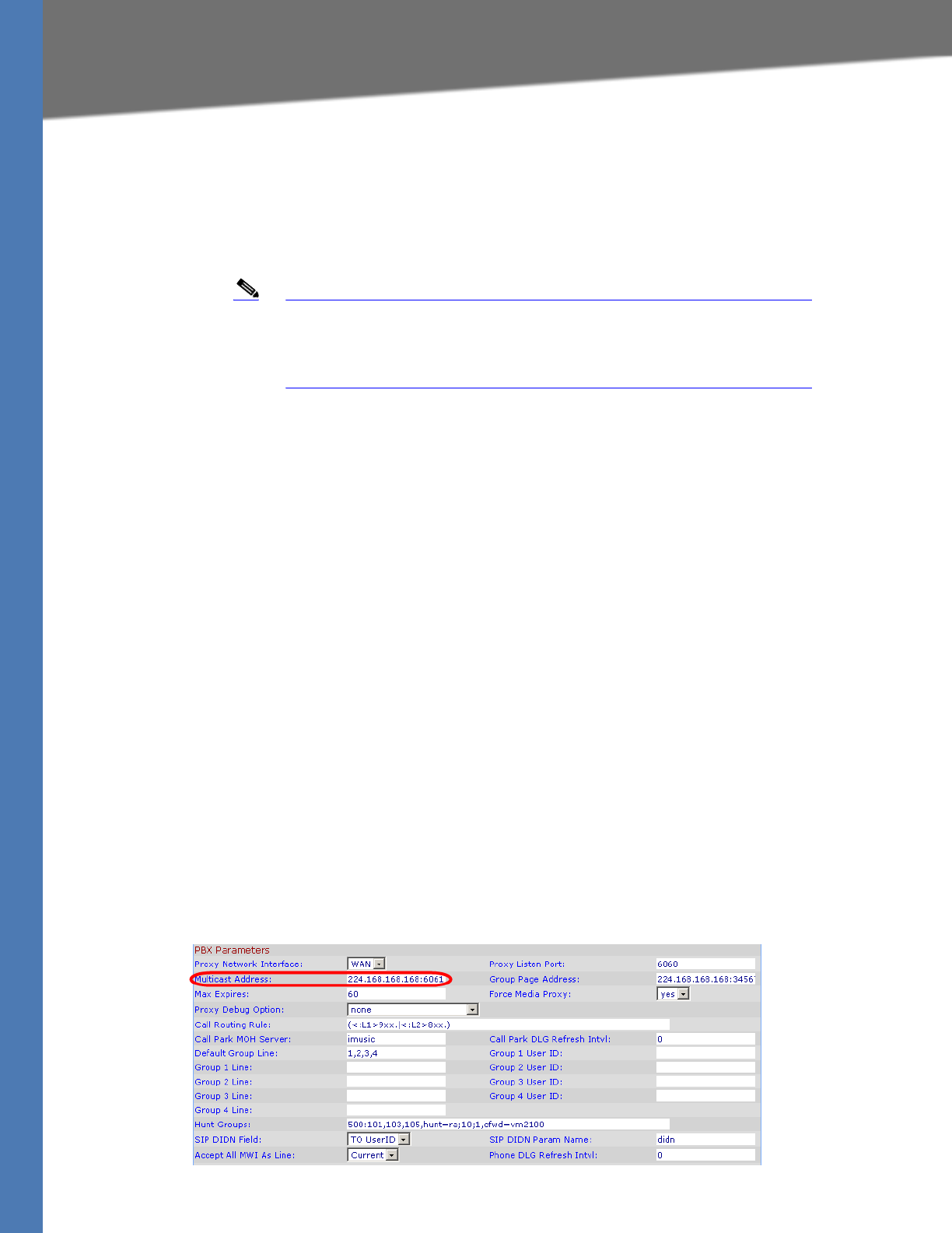
2. Click Voice tab > SIP.
3. Scroll down to the PBX Parameters section.
4. Enter the correct multicast address in the Multicast Address field.

Linksys Voice System Administration Guide 30
Configuring Basic Settings
Basic Administration of the SPA9000
NOTE: The default value is 224.168.168.168:6061.
5. Click Submit All Changes.
6. Enter the same multicast address in the phone configurations:
a. Click the PBX Status link to view a list of all phones.
b. Find the phone that you want to configure, and then click the hyperlink in the IP Address
column. The Telephone Configuration page appears in a separate browser window.
c. Click the SIP tab.
d. Scroll down to the Linksys Key System Parameters section.
e. Enter the IP address in the Multicast Address field.
f. Click Submit All Changes.
g. Click the Back button on the Internet Explorer toolbar to return to the list of phones.
h. Repeat these steps for each phone.
Setting the Group Page Address
In the group paging application, the originator sends RTP packets to an IP multicast address at
which all the other client stations are listening. This address is chosen by the SPA9000 and is
configured on the Voice > SIP page, PBX Parameters section, Group Page Address field.
The originator starts the group page by choosing PageGroup from the Corporate Directory on
the phone, or by using a speed dial or personal directory entry. All client stations are alerted at
once. If the client station is on a call when a group page starts, the call is automatically placed
on hold. The speaker on each paged station is turned on automatically unless the handset or
headset is being used. Group page is one-way only. The paged client stations can only listen to
the call from the originator.
1. Connect to the SPA9000 administration web server, and choose Admin access with
Advanced settings. (See ”Connecting to the SPA9000 Administration Web Server,” on
page 24).
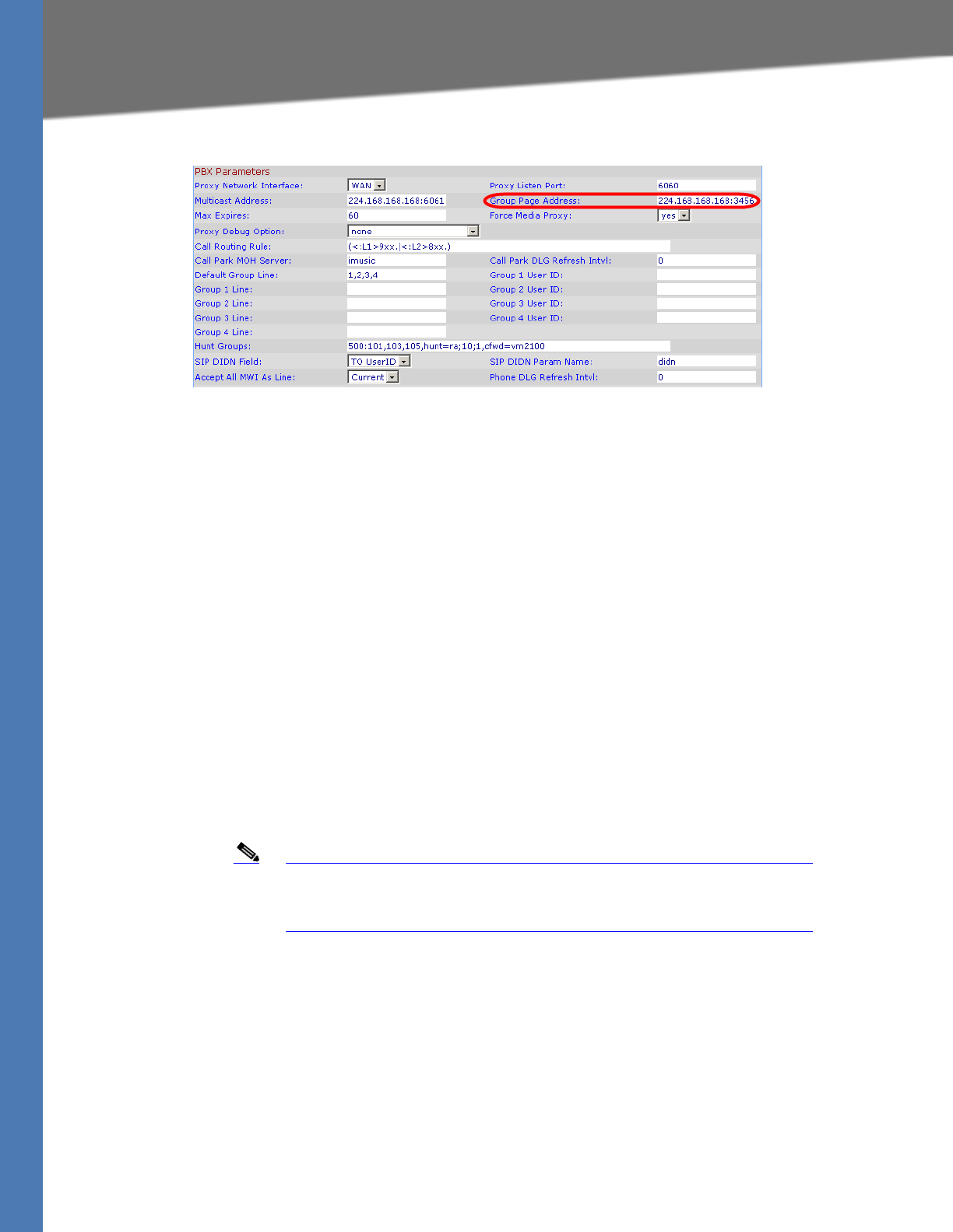
2. Click Voice tab > SIP.
3. Scroll down to the PBX Parameters section.
Linksys Voice System Administration Guide 31
Configuring Basic Settings
Basic Administration of the SPA9000
4. Enter the correct multicast address in the Group Page Address field.
NOTE: The default value is 224.168.168.168:34567.
5. Click Submit All Changes.
Collecting System Logs and Debug Information
If you are working with an ITSP that needs more information to configure interoperability, you
can collect system logs and debug information for the SPA9000. You can send these logs to the
ITSP for their use.
Requirements:
• You need a PC that is on the same subnetwork as the SPA9000, to capture the log files.
This PC needs to be running a syslog daemon. Enter the IP address of this PC on the
Voice > System page, in the Syslog Server and Debug Server fields.
• If you are interested in working with these logs yourself, you will need to use an
application that reads syslogs. Linksys partners can download a syslog server tool
(slogsrv.exe) from the Linksys Partner Connection. (VARs, see Product Utilities > Linksys
Voice System > SPA Utilities > Syslog Server for SPA Devices. SPs, see Technical Tools >
SPA Utilities > Syslog Server for SPA Devices.)
Note As a best practice, enable logging only when needed, and disable
logging when you finish the investigation. Logging information can
impact system performance.
1. Connect to the SPA9000 administration web server, and choose Admin access with
Advanced settings. (See ”Connecting to the SPA9000 Administration Web Server,” on
page 24).
2. Click Voice tab > System.

Linksys Voice System Administration Guide 32
Configuring Basic Settings
Basic Administration of the SPA9000
3. In the Miscellaneous Settings section, enter the following settings:
•Syslog Server: Enter the server IP address and port to collect basic information about
system activity (no SIP messages).
•Debug Server: Enter the server IP address and port to collect information about SIP
messages.
NOTE: SIP logging is not enabled until you complete this procedure by enabling system
logging on the line interface.
i. Debug Level: Choose 3 to enable debugging.
4. Click Voice tab > Line N, where N represents the line interface number of the line that you
are investigating.
5. Scroll down to the SIP Settings section, and then choose a SIP Debug Option, based on the
level of SIP information that you want to collect.
NOTE: Typically, your ITSP support personnel will tell you what type of information they
need in the logs. The drop-down list includes three categories of options: none,1- line, and
full.
•none: Disables SIP logging
• 1-line: Identifies the SIP message type but does not include the message body
Options within this category allow you to choose to exclude OPT, NTFY, and REG
information to reduce the length of the logs.
• full: Includes the SIP message body
Options within this category allow you to choose to exclude OPT, NTFY, and REG
information to reduce the length of the logs.
EXAMPLES:
• If you are troubleshooting a problem with line registration. Select full.
• If you are troubleshooting a call problem. Select full excl. OPT|NTFY|REG.
6. Click Submit All Changes. The information is stored on the specified server and port, with a
file name in the following format: syslog.port.log.
7. IMPORTANT: When you finish collecting the information, disable the logging:
a. Click Voice tab > Line. Change SIP Debug Option to none.
b. Click Voice tab > System. In the Miscellaneous Settings section, change Debug Level
to 0.
Linksys Voice System Administration Guide 33
Viewing Information about the SPA9000
Basic Administration of the SPA9000
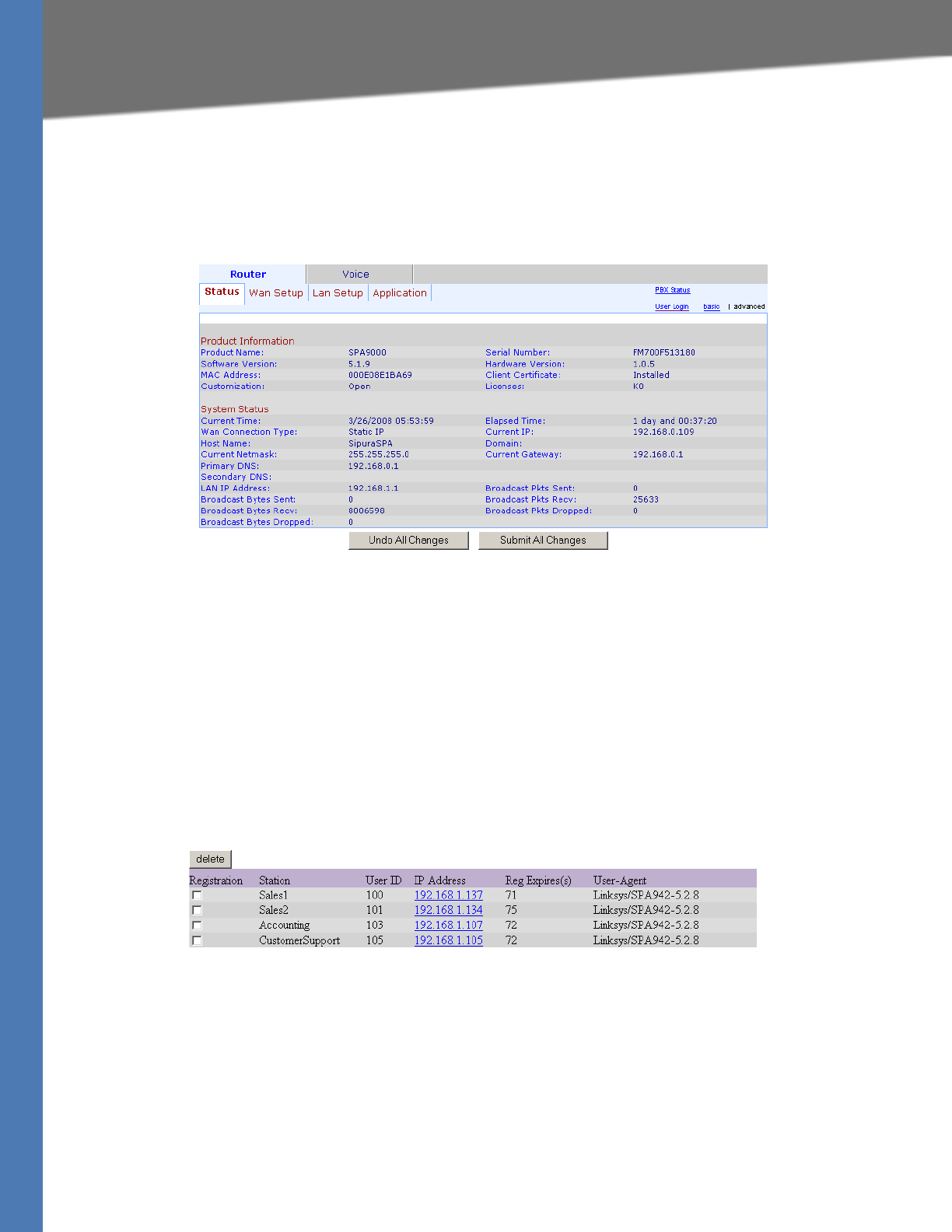
Viewing Information about the SPA9000
The Router Status page provides information about software version, hardware version, MAC
address, WAN connection type, IP address, and the packets that have been sent and received.
SPA9000 Router > Status
Viewing Information about Client Stations
The PBX Status page provides information about the client stations (IP phones), with hyperlinks
to station configuration pages.
1. Connect to the SPA9000 administration web server, and choose Admin access with
Advanced settings. (See ”Connecting to the SPA9000 Administration Web Server,” on
page 24).
2. To view the status information for the client stations, click the PBX Status link in the top
right corner or lower left corner of the page. The list of client stations appears.
SPA9000 > PBX Status
3. To view the Telephone Configuration page for any station, click the hyperlink in the IP Address
column. For information about the telephone configurations, see the Linksys Phone
Administration Guide.
Using the Interactive Voice Response Unit
In addition to the administration web server, the SPA9000 is equipped with an Interactive Voice
Response unit (IVR) that allows you to perform certain administrative tasks by using an analog
phone that is connected to the SPA9000.

Linksys Voice System Administration Guide 34
Using the Interactive Voice Response Unit
Basic Administration of the SPA9000
•”Using the IVR Menu,” on page 34
•”Entering a Password through the IVR,” on page 37
Using the IVR Menu
To use the IVR menu, complete the following steps.
1. Connect an analog telephone to the Phone 1 or Phone 2 port of the SPA9000.
2. Press **** (quickly press the star key four times).
3. Wait until you hear “Linksys configuration menu.”
4. Refer to Table 2-1 to identify the option required.
5. Enter the required option followed by the # (pound) key.
NOTE:
• To enter a period, use the star key (*).
• When entering a value, such as an IP address, to exit without entering any changes,
press the * (star) key twice within half a second. Otherwise, the * is treated as a decimal
point.
• After entering a value, such as an IP address, press the # (pound) key to indicate you
have finished your selection.
• To save a new setting, press 1. To review a new setting, press 2. To re-enter a setting,
press 3. To cancel your entry and return to the main menu, press * (star).
For example, to enter the IP address 191.168.1.105 by keypad, press the following keys:
191*168*1*105. Press the # (pound) key to indicate that you have finished entering the
IP address. Then press 1 to save the IP address, or press the * (star) key to cancel your
entry and return to the main menu.
• If the menu is inactive for more than one minute, the SPA9000 times out. You need to re-
enter the menu by pressing ****.
6. To exit the menu, hang up the telephone.
The settings that you have saved take effect after you hang up the telephone. The SPA9000
may reboot at this time.

Linksys Voice System Administration Guide 35
Using the Interactive Voice Response Unit
Basic Administration of the SPA9000
Table 2-1 IVR Options
IVR Action
IVR Menu
Choice Parameter(s) Notes
Enter IVR Menu * * * * None Ignore SIT or other tones until
you hear, “Linksys configuration
menu. Please enter option
followed by the pound key or
hang-up to exit.”
Exit IVR Menu 3948 None
Check DHCP 100 None The IVR spells "S,T,A,T,I,C" if the
setting is for a static IP address or
"D,H,C,P" for a DHCP IP address.
Enable/Disable
DHCP
101 Enter 0 to enable
Enter 1 to disable
Requires password
Check WAN IP
Address
110 None IVR announces the current IP
address of the WAN port.
Set Static IP
Address
111 Enter IP address using
numbers on the
telephone key pad. Use
the * (star) key when
entering a decimal
point.
DHCP must be “Disabled,”
otherwise you hear, “Invalid
Option,” if you try to set this
value. Hang up the phone after
setting the IP address. The
SPA9000 reboots and the new
address takes effect. Do not
attempt to use IVR option 110
immediately after changing the
IP address. The old IP address is
reported until the SPA9000
reboots.
Requires password
Check Network
Mask
120 None IVR announces the current
network mask of SPA.
Set Network Mask 121 Enter value using
numbers on the
telephone key pad. Use
the * (star) key when
entering a decimal
point.
DHCP must be “Disabled,”
otherwise you hear, “Invalid
Option,” if you try to set this
value.
Requires password
Check Static
Gateway IP
Address
130 None IVR announces the current
gateway IP address of SPA.

Linksys Voice System Administration Guide 36
Using the Interactive Voice Response Unit
Basic Administration of the SPA9000
Set Static Gateway
IP Address
131 Enter IP address using
numbers on the
telephone key pad. Use
the * (star) key when
entering a decimal
point.
DHCP must be “Disable,”
otherwise you hear, “Invalid
Option,” if you try to set this
value.
Requires password
Check MAC
Address
140 None IVR announces the MAC address
of SPA in hex string format.
Check Firmware
Version
150 None IVR announces the version of the
firmware running on the SPA.
Check Primary
DNS Server
Setting
160 None IVR announces the current
setting in the <Primary DNS>
parameter.
Set Primary DNS
Server
161 Enter IP address using
numbers on the
telephone key pad. Use
the * (star) key when
entering a decimal
point.
Requires password
Check
administration
web server port
170 None IVR announces the port that the
web server is listening on.
(Default is 80)
Check LAN IP
Address
210 None IVR announces the current IP
address of the LAN port.
Check PBX
multicast address
180 None IVR announces the current value.
Set PBX multicast
address
181 Enter IP address and
port. Use * key for
entering a dot. For
example,
224.168.168.169:8089 is
224*168*168*169*8089.
Enter a * between the IP address
and the Port fields. Requires
Password
Enable/Disable
administration
web server
7932 Enter 1 to enable
Enter 0 to disable
Requires password
Manual Reboot of
Unit
732668 None After you hear “Option
Successful,” hang up. Unit
reboots automatically.
Table 2-1 IVR Options (Continued)
Linksys Voice System Administration Guide 37
Using the Interactive Voice Response Unit
Basic Administration of the SPA9000
Note The items marked with “Requires Password” only require a password if
the Administrator password is set.
Entering a Password through the IVR
To input the password using the phone keypad, the following translation conventions
apply:
– To input: A, B, C, a, b, c—press “2’
– To input: D, E, F, d, e, f—press “3’
– To input: G, H, I, g, h, i—press “4’
– To input: J, K, L, j, k, l— press “5’
– To input: M, N, O, m, n, o—press “6’
– To input: P, Q, R, S, p, q, r, s—press “7’
User Factory Reset
of Unit
WARNING:
ALL “User-
Changeable”
NON-DEFAULT
SETTINGS WILL BE
LOST!
This might include
network and
service provider
data.
877778 Enter 1 to confirm
Enter *(star) to cancel
operation
SPA prompts for confirmation.
After confirming, you hear
“Option Successful.” Hang up.
Unit reboots and all “User
Changeable” configuration
parameters are reset to factory
default values.
Factory Reset of
Unit
WARNING:
ALL NON-DEFAULT
SETTINGS WILL BE
LOST!
This includes
network and
service provider
data.
73738 Enter 1 to confirm
Enter * (star) to cancel
operation
SPA prompts for confirmation.
After confirming, you hear
“Option Successful.” Hang up.
Unit reboots and all
configuration parameters are
reset to factory default values.
Table 2-1 IVR Options (Continued)

Linksys Voice System Administration Guide 38
Using the Interactive Voice Response Unit
Basic Administration of the SPA9000
– To input: T, U, V, t, u, v—press “8’
– To input: W, X, Y, Z, w, x, y, z—press “9’
– To input all other characters in the Administrator account password, press “0’
Note This translation convention only applies to the password input.
For example, to input password test#@1234 by phone keypad, you need to press the
following sequence of digits: 8378001234.
1. After entering a value, press the # (pound) key to indicate end of input.
• To save value, press 1.
• To review the value, press 2.
• To re-enter the value, press 3.
• To cancel the value entry and return to the main configuration menu, press *’ (star).
NOTES:
– The final # key is not included in the password value.
– Saved settings take effect when the telephone is hung-up, and if necessary, the
SPA9000 automatically reboots.
2. After one minute of inactivity, the unit times out. The user needs to re-enter the
configuration menu from the beginning by pressing * * * *.
Linksys Voice System Administration Guide 39
3About LVS and SIP
Configuring the SPA9000 for ITSP Interoperability
Configuring the SPA9000 for ITSP
Interoperability
This chapter provides configuration details for the purpose of helping you to ensure that your
infrastructure properly supports the LVS.
•”About LVS and SIP,” on page 39
•”Network Address Translation (NAT) and Voice over IP (VoIP),” on page 40
•”Firewalls and SIP,” on page 43
•”Configuring SIP Timer Values,” on page 44
About LVS and SIP
The LVS is implemented using open standards, such as Session Initiation Protocol (SIP), to help
ensure interoperation with all ITSPs that support SIP. This section provides information about
the SIP requests and the settings that you may need to adjust on your network or your SPA9000
to help ensure interoperability.
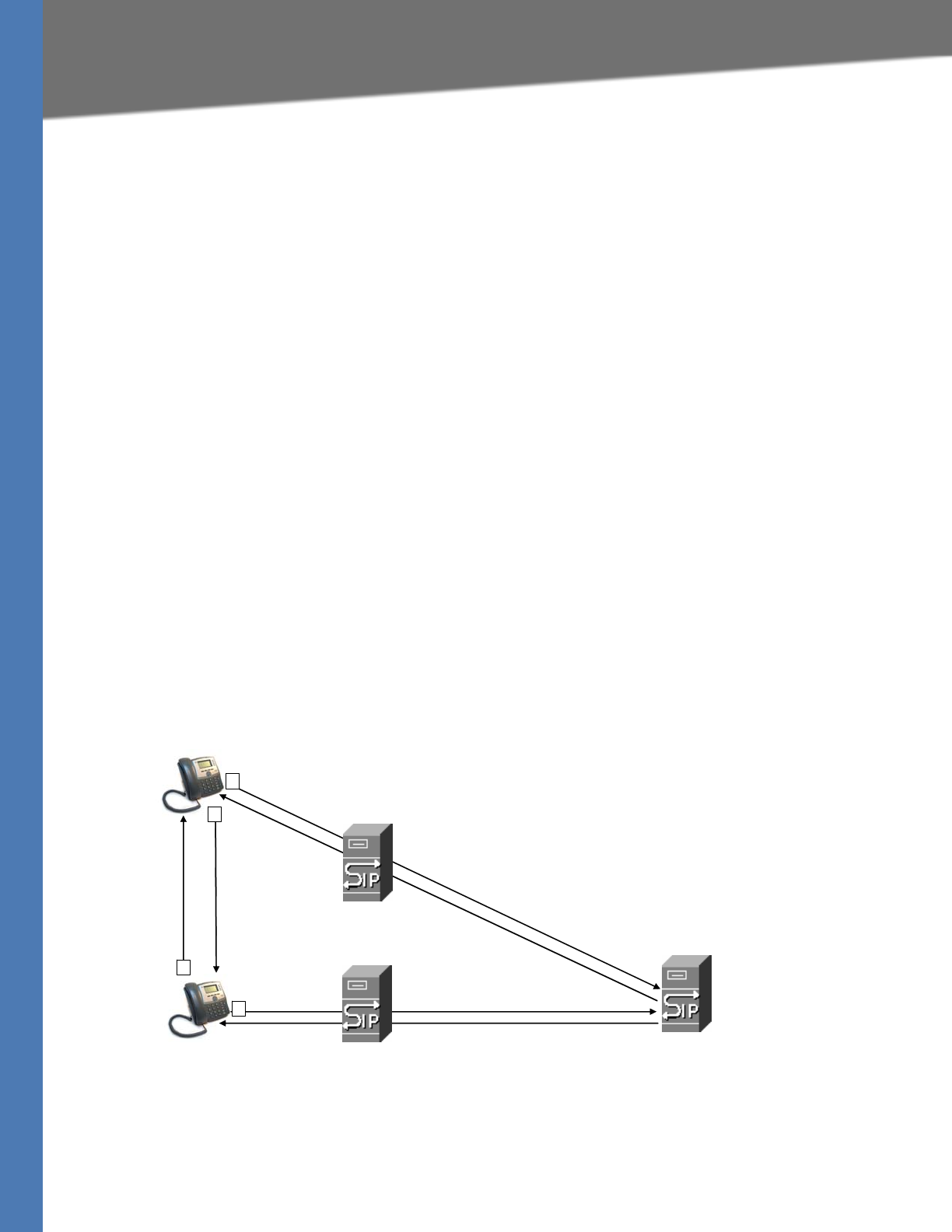
The VoIP telephone service is coordinated by SIP requests and responses, whether the calls are
internal or external. Figure 3-1 illustrates the SIP requests and responses between client
stations in the LVS. The SPA9000 acts as a SIP proxy and establishes a session. After the session
is established, Real Time Protocol (RTP) traffic flows directly between the two client stations.
Figure 3-1 SIP Requests and Responses for Internal Calls
Likewise, SIP requests and responses are exchanged to support outbound and inbound calls
that are handled through the ITSP service. In Figure 3-2, UserA and UserB are client stations that
are registered to the SPA9000. When UserA calls UserC, the SPA9000 directs the request to the
SIP proxy at the ITSP, which is then responsible for routing the request to UserC. After the
session is established, RTP is anchored by the SPA9000.
SIP UA
SIP UA
SIP Proxy
SIP Proxy
RTP
1
2
3
4
SIP Proxy
Linksys Voice System Administration Guide 40
Network Address Translation (NAT) and Voice over IP (VoIP)
Configuring the SPA9000 for ITSP Interoperability
Figure 3-2 SPA9000 as a SIP Proxy for Internet Calls
Network Address Translation (NAT) and Voice over IP (VoIP)
NAT is a function that allows multiple devices to share the same public, routable, IP address to
establish connections over the Internet. NAT is present in many broadband access devices to
translate public and private IP addresses. To enable VoIP to co-exist with NAT, some form of NAT
traversal is required.
Some ITSPs provide NAT traversal, but some do not. If your ITSP does not provide NAT traversal,
you have several options.
•”NAT Mapping with SIP-ALG Router,” on page 40
•”NAT Mapping with Session Border Controller,” on page 41
•”Configuring NAT Mapping with a Static IP Address,” on page 41
•”Configuring NAT Mapping with STUN,” on page 42
NAT Mapping with SIP-ALG Router
You can achieve NAT mapping by using a router that has a SIP ALG (Application Layer Gateway).
The Linksys WRV200 router is recommended for this purpose, although any router with a SIP-
ALG can be used. By using a SIP-ALG router, you have more choices in selecting an ITSP.
SIP Proxy with
media proxy enabled
Internet
IP Router (firewall)
Broadband modem
Hub/switch
SPA9000
UserA UserB
UserC
Internet (WAN)
Interface
ITSP
ISP
Linksys Voice System Administration Guide 41
Network Address Translation (NAT) and Voice over IP (VoIP)
Configuring the SPA9000 for ITSP Interoperability
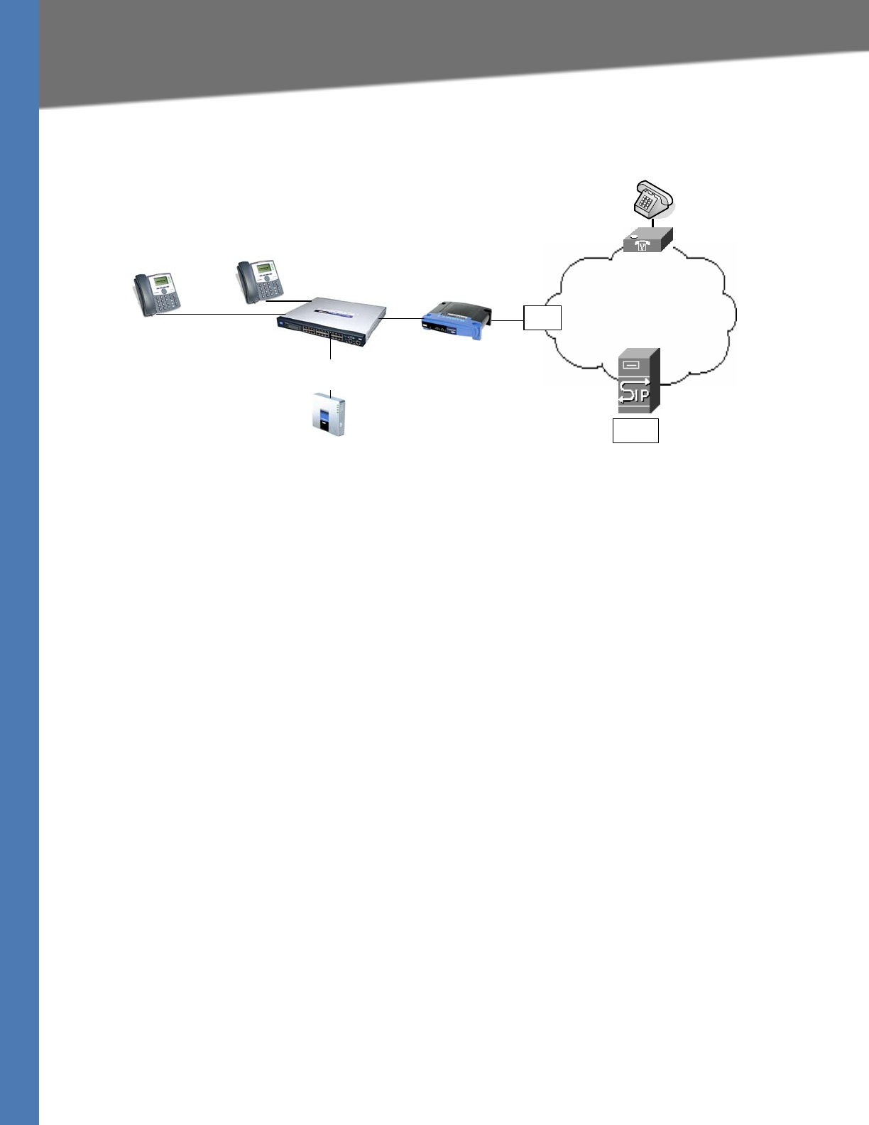
NAT Mapping with Session Border Controller
It is strongly recommended that you choose an ITSP that supports NAT mapping through a
Session Border Controller (see Figure 3-3). With NAT mapping provided by the ITSP, you have
more choices in selecting a router.
Figure 3-3 NAT Support with Session Border Controller Provided by ITSP
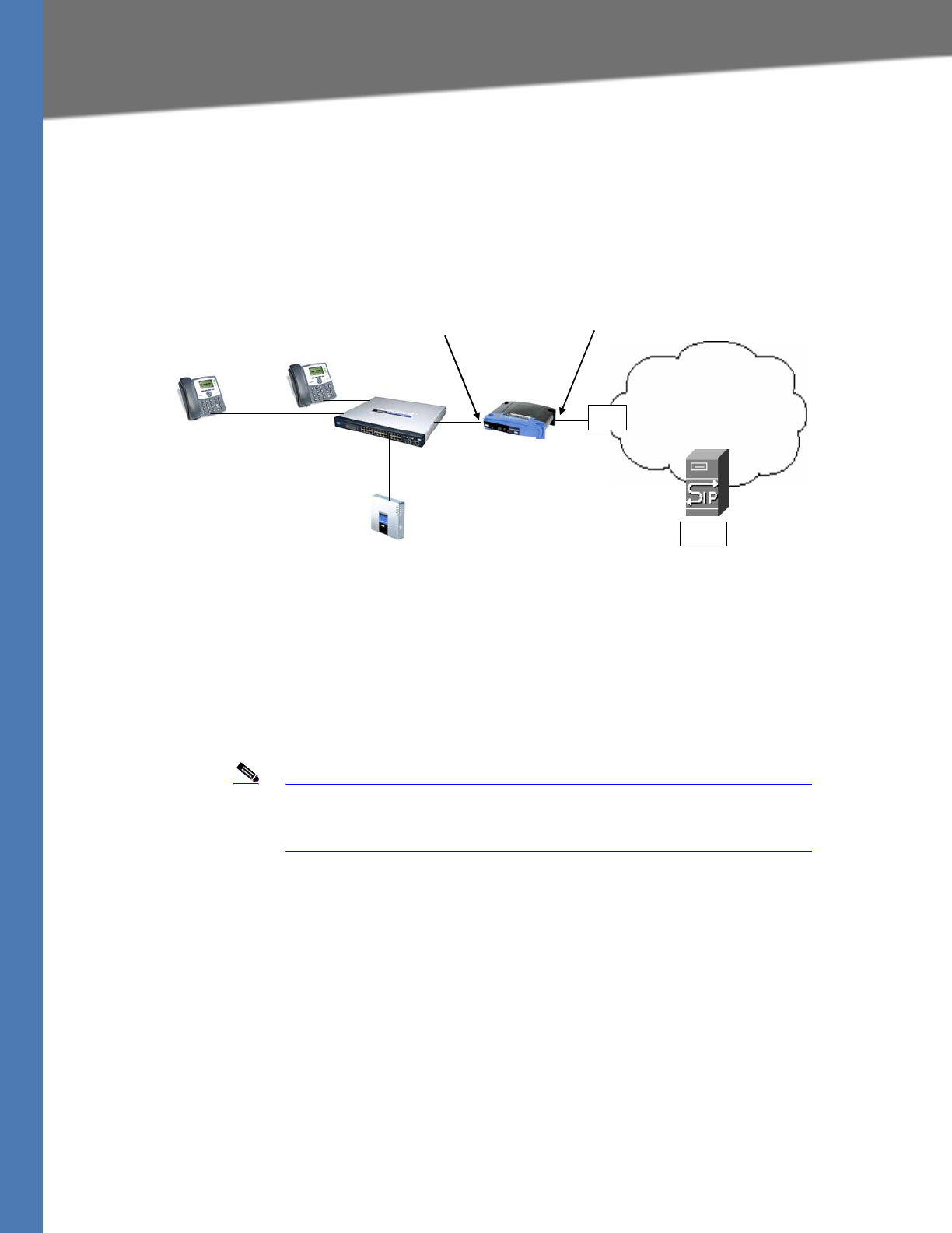
Configuring NAT Mapping with a Static IP Address
Configuring NAT mapping in the SPA9000 is recommended only if the ITSP network does not
provide a Session Border Controller functionality. In this case, and if the external (public) IP
address is static, then it is recommended to perform a static (permanent) mapping on SPA9000.
This setting is also recommended if NAT mechanism used in the router is symmetric.
Note The LAN switch needs to be configured to enable Spanning Tree
Protocol and Port Fast on the ports to which the SPA9000 and the
SPA9xx phones are connected.
1. Connect to the SPA9000 administration web server, and choose Admin access with
Advanced settings. (See ”Connecting to the SPA9000 Administration Web Server,” on
page 24.)
2. Click Voice tab > SIP.
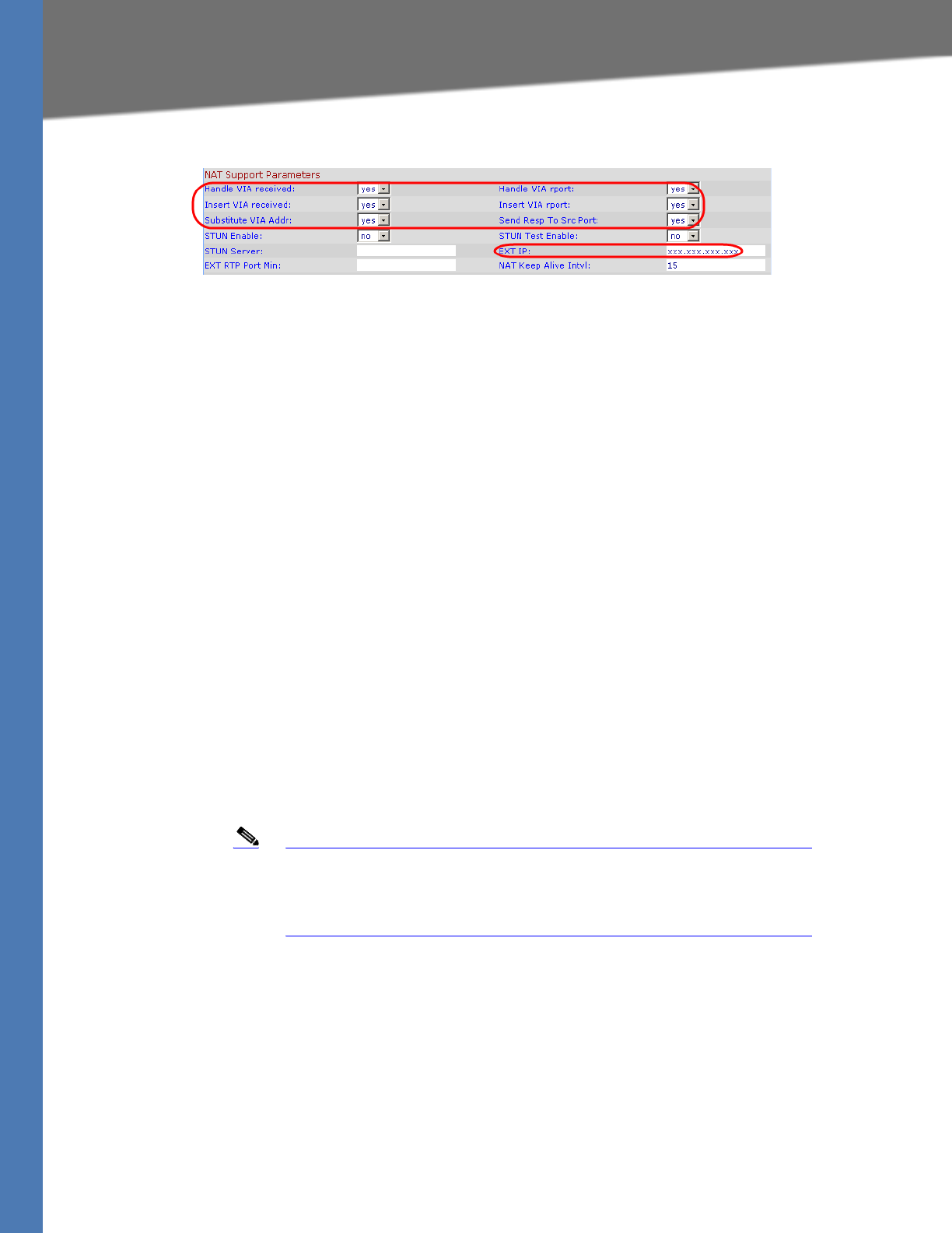
3. Scroll down to the NAT Support Parameters section, and then enter the following settings to
support static mapping to your public IP address:
•Handle VIA received, Insert VIA received, Substitute VIA Addr: yes
•Handle VIA rport, Insert VIA rport, Send Resp To Src Port: yes
•EXT IP: Enter the public IP address for your router.
SIP Proxy
Internet
ITSP
NAT Device
SPA9000
192.168.1.102
ISP
DHCP
server
192.168.1.101
192.168.1.100 Session Border
Controller
Private IP address
192.168.1.1 External IP address
assigned by ISP
Router and
DHCP Server
Linksys Voice System Administration Guide 42
Network Address Translation (NAT) and Voice over IP (VoIP)
Configuring the SPA9000 for ITSP Interoperability
SPA9000 Voice > SIP: NAT Support Parameters
4. Click Voice tab > Line N, where N is the number of the line interface for the ITSP service that
you need to configure.
5. Scroll down to the NAT Settings section.
•NAT Mapping Enable: Choose YES.
•NAT Keep Alive Enable: Choose YES (optional).
NOTE: Your ITSP may require the SPA9000 to send NAT keep alive messages to keep the
NAT ports open permanently. For more information, see Appendix A, "Advanced Topics
in LVS Administration," ”SIP-NAT Interoperation” section on page 135.
6. Click Submit All Changes.
NOTE: You also need to configure the firewall settings on your router to allow SIP traffic. See
”Firewalls and SIP,” on page 43.
Configuring NAT Mapping with STUN
Configuring NAT mapping in the SPA9000 is recommended only if the ITSP network does not
provide a Session Border Controller functionality. In this case, and if the external (Public) IP
address is assigned dynamically by the network (and the router uses asymmetric NAT
mechanism), it is possible to use STUN as a mechanism to discover the NAT mapping in
SPA9000. This is considered a practice of last resort and should be used only if the other
methods are unavailable.
Note STUN is a viable option only if your router uses asymmetric NAT. See
Appendix A, "Advanced Topics in LVS Administration," ”Determining
Whether the Router Uses Symmetric or Asymmetric NAT” section on
page 136.
1. Connect to the SPA9000 administration web server, and choose Admin access with
Advanced settings. (See ”Connecting to the SPA9000 Administration Web Server,” on
page 24.)
2. Click Voice tab > SIP.

Linksys Voice System Administration Guide 43
Firewalls and SIP
Configuring the SPA9000 for ITSP Interoperability
3. Scroll down to the NAT Support Parameters section, and then enter the following settings to
enable and support the STUN server settings:
•Handle VIA received, Insert VIA received, Substitute VIA Addr: yes
•Handle VIA rport, Insert VIA rport, Send Resp To Src Port: yes
•STUN Enable: Choose yes.
•STUN Server: Enter the IP address for your STUN server.
4. Click Voice tab > Line N, where N is the number of the line interface for the ITSP service that
you need to configure.
5. Scroll down to the NAT Settings section.
•NAT Mapping Enable: Choose YES.
•NAT Keep Alive Enable: Choose YES (optional).
NOTE: Your ITSP may require the SPA9000 to send NAT keep alive messages to keep the
NAT ports open permanently. For more information, see Appendix A, "Advanced Topics
in LVS Administration," ”SIP-NAT Interoperation” section on page 135.
6. Click Submit All Changes.
NOTE: You also need to configure the firewall settings on your router to allow SIP traffic. See
”Firewalls and SIP,” on page 43.
Firewalls and SIP
To enable SIP requests and responses to be exchanged with the SIP proxy at the ITSP, you must
ensure that your firewall allows both SIP and RTP unimpeded access to the Internet.
• Make sure that the following ports are not blocked:
– SIP ports—UDP port 5060 through 5063, which are used for the SPA9000 line
interfaces
– RTP ports—16384 to 16482
• Also disable SPI (Stateful Packet Inspection) if this function exists on your firewall.

Linksys Voice System Administration Guide 44
Configuring SIP Timer Values
Configuring the SPA9000 for ITSP Interoperability
Configuring SIP Timer Values
The SPA9000 is configured with default timer values that should be adequate in most
circumstances. However, you can adjust the SIP timer values as needed to ensure
interoperability with your ISTP. For example, if SIP requests are returned with an “invalid
certificate” message, you may need to enter a longer SIP T1 retry value.
To view the default settings or to make changes, open the Voice > SIP page, and scroll down to
the SIP Timer Values section. For field descriptions, see ”SIP Timer Values (sec) section,” on
page 161.

Linksys Voice System Administration Guide 45
4Configuring SPA9000 FXS Ports
Configuring Phone Lines and Calling Routing Behavior
Configuring Phone Lines and Calling
Routing Behavior
This chapter describes many features that you can configure on the SPA9000 to ensure smooth
handling of all inbound and outbound calls, and ease of use.
•”Configuring SPA9000 FXS Ports,” on page 45
•”Configuring Line Interfaces on the SPA9000,” on page 46
•”Configuring Dial Plans,” on page 52
•”Managing the Line Selection for Outbound Calls,” on page 63
•”Managing Caller ID Settings for Outgoing Calls,” on page 65
•”Managing Inbound Calls with the Contact List,” on page 66
•”Managing Inbound Calls with Hunt Groups,” on page 73
•”Managing Inbound Calls with Shared Line Appearances,” on page 77
Configuring SPA9000 FXS Ports
The SPA9000 FXS ports can be used to connect analog phones and fax machines to the LVS. A
port also can be configured for a Streaming Audio Server for Music On Hold. See Chapter 6,
"Configuring Music on Hold."
Note A fax machine can be connected to the Phone port of the SPA9000. Fax
support through an ITSP line requires a T.38 fax machine on both ends
and the availability of T.38 FAX relay through the ITSP. T.38 support is
dependent on fax machine and network / transport resilience. Linksys
makes no guarantee with the use of this product regarding fax
transmission services
1. Connect to the SPA9000 administration web server, and choose Admin access with
Advanced settings. (See ”Connecting to the SPA9000 Administration Web Server,” on
page 24.)
2. Click Voice tab > FXS N, where N is the port number.
3. Scroll down to the Subscriber Information section, and then enter the following settings:
•Display Name: Enter an extension number of name for the FXS 1 port, such as
Receptionist Area Fax Machine. You can use this extension number to add the analog
phone to the contact list, hunt groups, and shared line appearances.
•User ID: Enter a three- to four-digit extension number that is not is use by other
extension.

Linksys Voice System Administration Guide 46
Configuring Line Interfaces on the SPA9000
Configuring Phone Lines and Calling Routing Behavior
• If the device is a fax machine, disable echo cancelling. On the FXS N page, Audio
Configuration section, set the FAX Disable ECAN field to yes. Also make sure that the
Preferred Codec is set to G.711u (default setting).
4. Enter the Dial Plan settings, as needed. See ”Configuring Dial Plans,” on page 52.
5. Click Submit All Changes.
Configuring Line Interfaces on the SPA9000
You can configure the following types of services on the SPA9000 line interfaces:
•ITSP service: Up to 16 DID numbers can be supported on each line interface. You can
configure different ITSP accounts on different line interfaces.
•PSTN service: You can configure a line interface to register the SPA9000 with a SPA400
to support PSTN lines.
•SPA400 voice mail service: You can configure a line interface to register the SPA9000
with a SPA400 to support voice mail server. This SPA400 should have no more than two
PSTN lines connected. If more than two PSTN lines and voice mail are required, you
should reserve one SPA400 exclusively for voice mail. Exceeding these guidelines will
affect the quality of voice mail playback and command recognition.
•ISDN services: You can configure a line interface to register the SPA9000 with a
Mediatrix® 4400 ISDN BRI Digital gateway. For more information, refer to the SPA9000/
Mediatrix® 440X ISDN Gateway Configuration Guide, available at www.linksys-itsp.com
(for Europe, Middle East and Africa Service Providers) and www.linksys-voip.eu (for
Europe, Middle East and Africa Value Added Resellers).
This section includes the following topics:
•”Configuring a Line Interface for ITSP Service,” on page 46
•”Configuring a Line Interface for a SPA400 (PSTN or Voice Mail),” on page 48
•”Configuring Call Capacity for a Line Interface,” on page 51
Configuring a Line Interface for ITSP Service
1. Connect to the SPA9000 administration web server, and choose Admin access with
Advanced settings. (See ”Connecting to the SPA9000 Administration Web Server,” on
page 24.)
2. Click Voice tab > Line N, where N represents the line interface number.
3. From the Line Enable drop-down list, choose yes.
4. Enter the account information for your ITSP account:
User ID: The account number or logon name for your ITSP account (often the same as the phone
number)
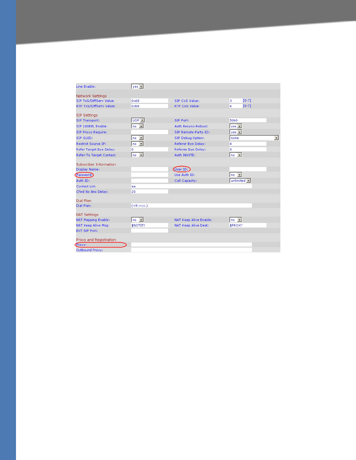
Linksys Voice System Administration Guide 47
Configuring Line Interfaces on the SPA9000
Configuring Phone Lines and Calling Routing Behavior
Password: The password for your ITSP account
Proxy: The proxy server for your ITSP account
SPA9000 Voice > Line
NOTES:
•SIP Port: You can keep the default value. Each line must have a unique SIP port (5060 for
Line 1, 5061 for Line 2, 5062 for Line 3, 5064 for Line 4).
•Contact List: The default value is aa, for the Auto Attendant. As a general practice, you
should leave the default value until after you confirm that the line is registered. Then
you can configure the contact list. For more information, see ”Managing Inbound Calls
with the Contact List,” on page 66.
• Depending on your ITSP network configuration requirements, you may need to set
additional parameters such as Outbound Proxy. Service Provider will indicate the
setting of any additional parameter for each ITSP line.
5. Click the Submit All Changes button. The SPA9000 device reboots.
6. To verify the registration state, perform the following tasks:
•After the devices reboot, Click Voice tab > Info. Scroll down to the Line Status section for
the line that you configured (Line 1 Status ... Line 4 Status). Verify that the line is
registered. If the line is not registered, you may need to refresh the browser several
times because it can take a few seconds for the registration to succeed.
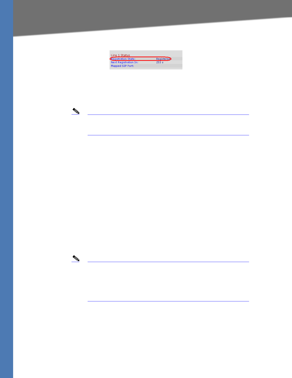
Linksys Voice System Administration Guide 48
Configuring Line Interfaces on the SPA9000
Configuring Phone Lines and Calling Routing Behavior
SPA9000 Voice > Info > Line Status
• Use an external phone to place an inbound call to the telephone number that was
assigned by your ITSP. Assuming that you have left the default settings in place, the
Auto Attendant answers the call. You can then dial an extension number to verify that
the call rings to the station.
Note The LVS can be configured to support multiple DIDs per Line Interface.
For more information, ”Supporting Direct Inward Dialing to Phone
Extensions,” on page 69.
Configuring a Line Interface for a SPA400 (PSTN or Voice Mail)
You can configure a line interface to register the SPA9000 to a SPA400 for PSTN access or voice
mail service. To enable the interoperation of the SPA9000 and the SPA400, you need to enter
corresponding information on the SPA9000 Voice > Line page and on the SPA400 Setup >
SPA9000 Interface page. For voice mail service, also configure the SPA400 Setup > Voicemail
Server page.
NOTE:
• The SPA9000 registers to the SPA400. Therefore, the SPA400 must be available when the
SPA9000 attempts to register to it.
• Before you begin this procedure, connect the SPA400 as described in either the SPA400
Quick Install Guide or the LVS Installation and Configuration Guide.
• Determine the DHCP-obtained IP address of the SPA400 by reviewing the DHCP client list
on the router.
Note Important: For optimum Voice Mail performance, a SPA400 should be
dedicated to the Voice Mail application when either of the following
conditions is met:
1) More than 2 FXO connections are required
—OR—
2) More than 2 users commonly access voice mail at the same time.
1. Connect to the SPA9000 administration web server, and choose Admin access with
Advanced settings. (See ”Connecting to the SPA9000 Administration Web Server,” on
page 24.)
2. Click Voice tab > Line N, where N represents the line interface number.
3. From the Line Enable drop-down list, choose yes.
4. Enter the following information:
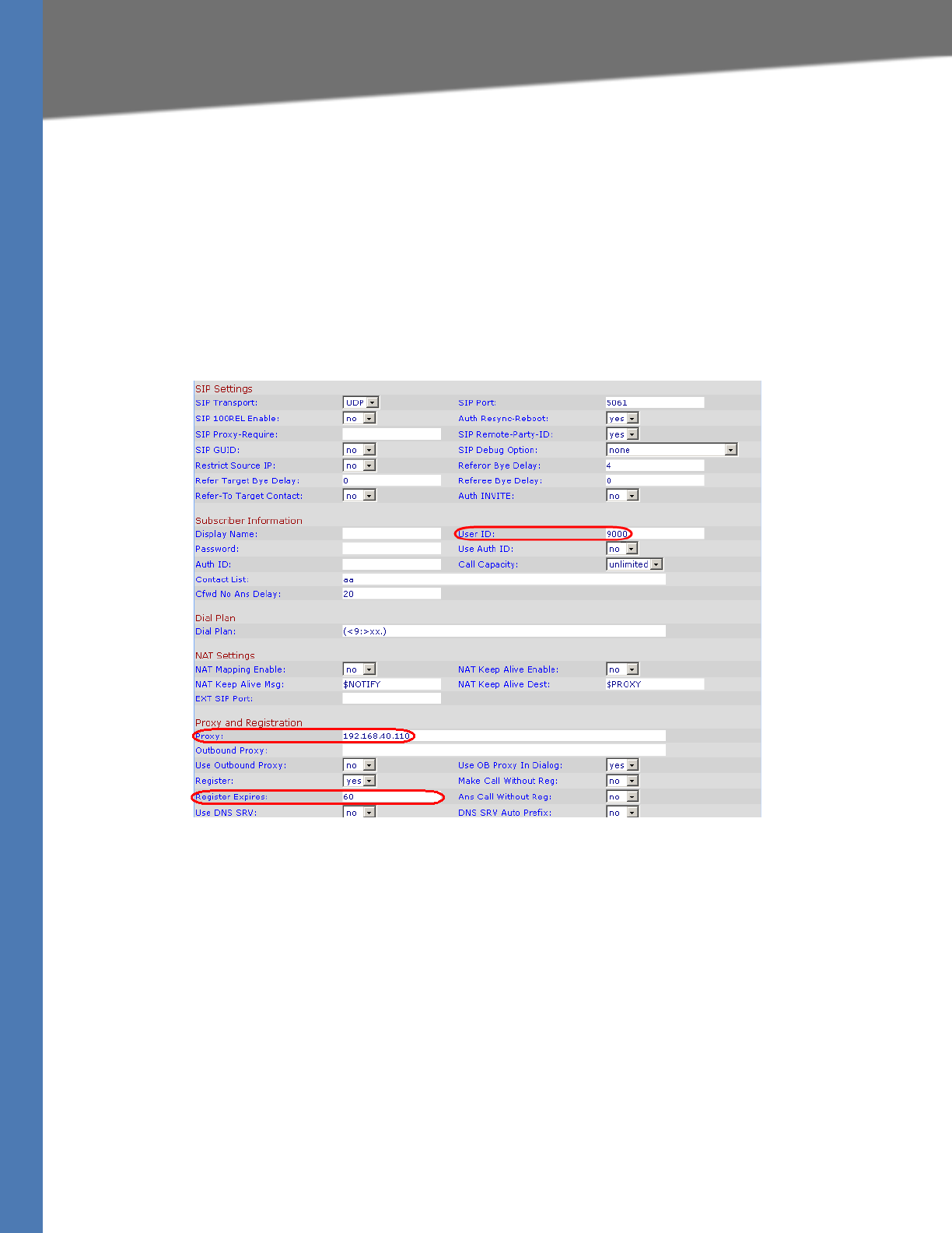
Linksys Voice System Administration Guide 49
Configuring Line Interfaces on the SPA9000
Configuring Phone Lines and Calling Routing Behavior
•User ID: Enter a user ID, such as 9000.
This entry must exactly match the user ID on the SPA400 Setup > SPA9000 Interface page,
User ID field. For more information, see ”Configuring a SPA400 to Interoperate with the
SPA9000,” on page 85.
•Proxy: Enter the IP address of the SPA400.
•Register Expires: 60
This setting ensures that the SPA9000 and SPA400 are resynchronized every 60 seconds.
This setting ensures that any changes in settings are synchronized on both devices.
SPA9000 Voice > Line: Subscriber Information, Proxy and Registration
5. Also in the Proxy and Registration section, enter the following settings to ensure that calls
can be transferred and forwarded to the voice mail server:
•Set VMSP Bridge to all (required if this line is being used for SPA400 voice mail service).
•Set XFER Bridge Mode to all.
•Set CFWD Bridge Mode to all.
NOTES:
•SIP Port: You can keep the default value. Each line must have a unique SIP port (5060 for
Line 1, 5061 for Line 2, 5062 for Line 3, 5064 for Line 4).
•Contact List: The default value is aa, for the Auto Attendant. As a general practice, you
should leave the default value until after you confirm that the line is registered in the
Voice > Info page, Line Status section, Registration State field. Then you can configure the
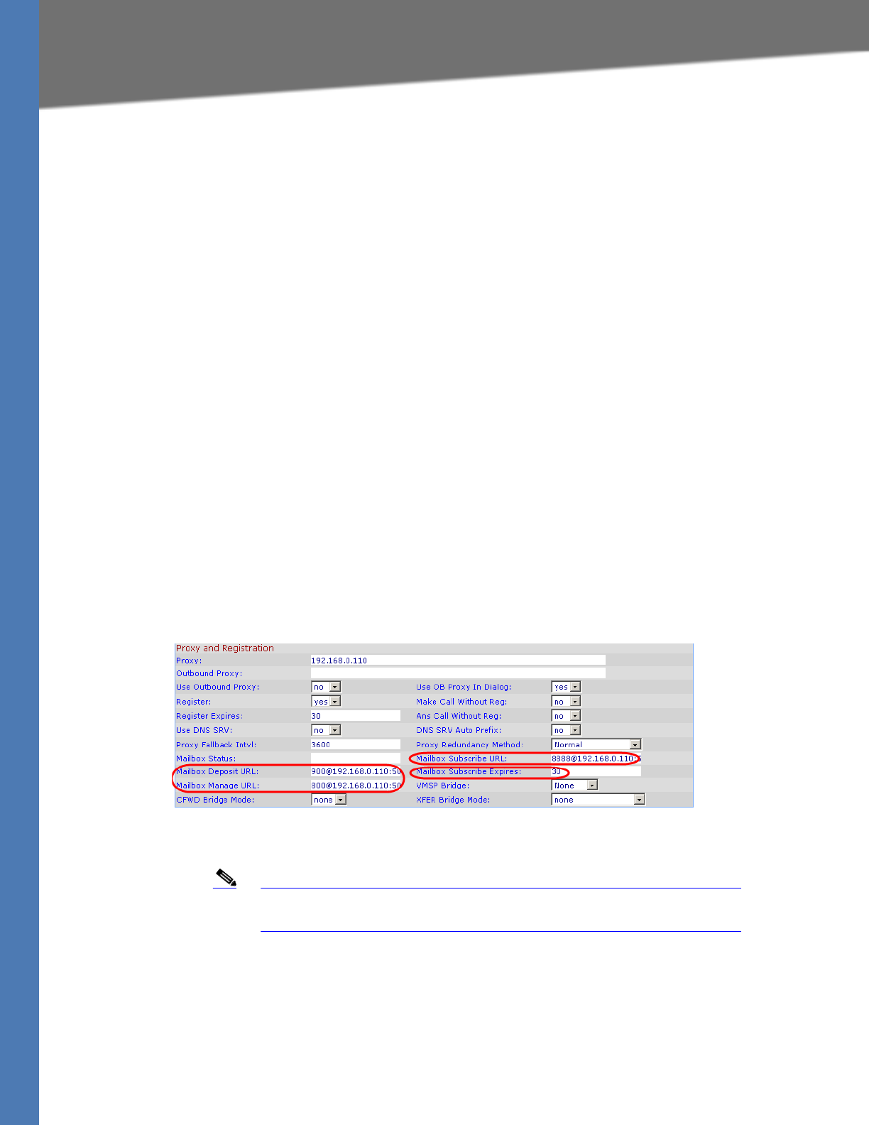
Linksys Voice System Administration Guide 50
Configuring Line Interfaces on the SPA9000
Configuring Phone Lines and Calling Routing Behavior
contact list. For more information, see ”Managing Inbound Calls with the Contact List,”
on page 66.
6. Proceed as needed:
• If you are using this SPA400 for voice mail service, continue to Step 7.
• If you are using this SPA400 for PSTN access only, click Submit All Changes to finish this
procedure. You will need to configure the SPA400. For more information, see
”Configuring a SPA400 to Interoperate with the SPA9000,” on page 85 and ”Configuring
a SPA400 for PSTN Access,” on page 87.
7. Enter the following settings for the SPA400 voice mail service:
•Mailbox Deposit URL: 900@<IP address of SPA400>:5090
The SPA9000 uses this address to deposit voice mail on the voice mail server.
•Mailbox Manage URL: 800@<IP address of SPA400>:5090
The SPA9000 uses this address to access voice mail on the voice mail server.
•Mailbox Subscribe URL: 8888@<IP address of SPA400>:5090
The SPA9000 uses this address to subscribe to voice mail service on the voice mail
server.
•Mailbox Subscribe Expires: 30
This setting ensures that the SPA9000 and the SPA400 voice mail server are
resynchronized every 30 seconds, and prevents problems when you make changes in
the settings.
SPA9000 Voice > Line
8. Click the Submit All Changes button. The SPA9000 device reboots.
Note You need to configure the SPA400 with the corresponding settings. See
”Configuring Local Voice Mail Service on a SPA400,” on page 88.

Linksys Voice System Administration Guide 51
Configuring Line Interfaces on the SPA9000
Configuring Phone Lines and Calling Routing Behavior
Configuring Call Capacity for a Line Interface
Each line interface has a limited number of simultaneous calls that are allowed, based on the
Call Capacity parameter. When the maximum call capacity is reached, the SPA9000 does not
allocate any more calls to that line interface.
This section includes the following topics:
•”Bandwidth Requirements and Call Capacity,” on page 51
•”Setting the Call Capacity Parameter,” on page 52
Bandwidth Requirements and Call Capacity
The available connection bandwidth determines the maximum number of simultaneous calls
that the system can support with the appropriate audio quality. Before installing and
configuring the LVS components, use this information to determine the maximum number of
simultaneous VoIP connections that the system can support. For asymmetric connections, such
as ADSL, the maximum number of calls is determined by the upstream bandwidth. In general it
is a good practice to use no more than 75% of the total available bandwidth for calls. This
provides space for data traffic and helps ensure good voice quality.
Table 4-1 provides the approximate bandwidth budget for different codecs.
Table 4-1 Bandwidth Budget
Codec
Approximate bandwidth budget (kbps)
Each side of
conversation 2 calls 4 calls 6 calls 8 calls
G.711 110 220 440 660 880
G.726-40 87 174 348 522 696
G.726-32 79 158 316 474 632
G.726-24 71 142 284 426 568
G.726-16 63 126 252 378 504
G.729 55 110 220 330 440
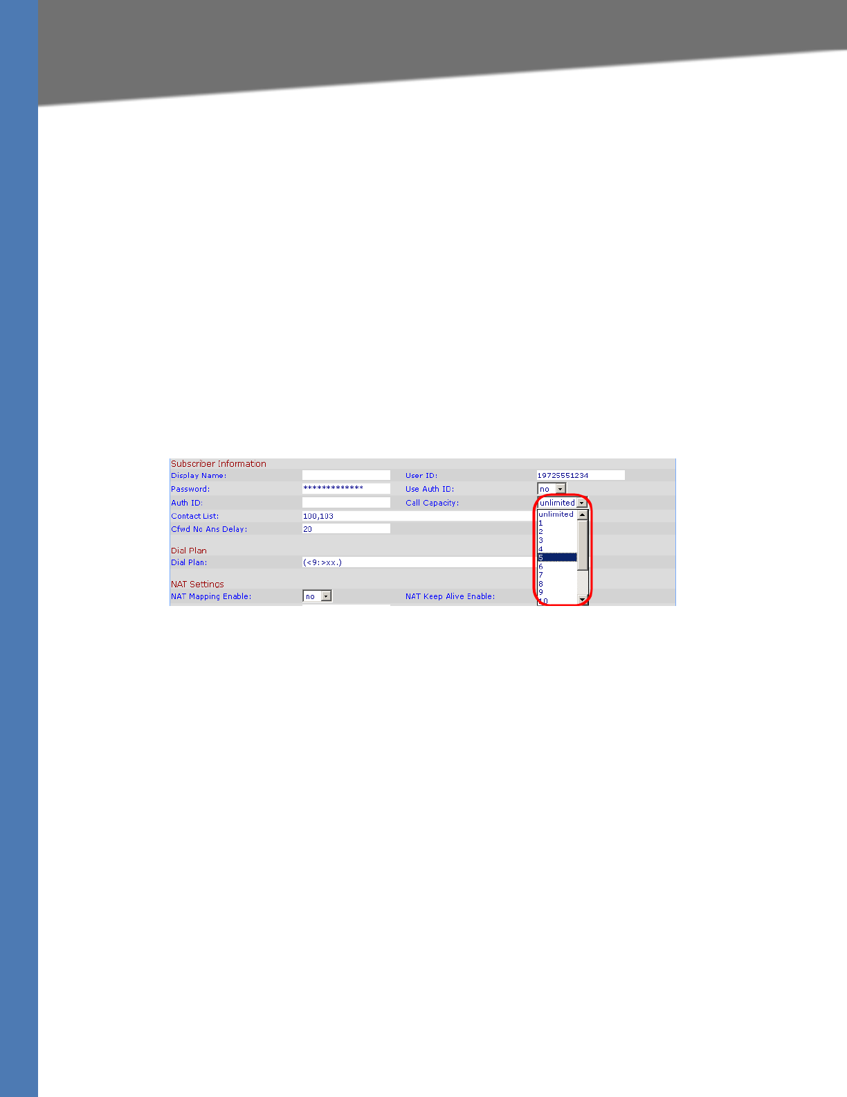
Linksys Voice System Administration Guide 52
Configuring Dial Plans
Configuring Phone Lines and Calling Routing Behavior
Setting the Call Capacity Parameter
You can set the maximum total number of incoming and outgoing calls on each line interface.
The default value is unlimited. You can set a value from 1 to 15, or leave the setting as unlimited.
NOTE: The SPA9000 does not distinguish between incoming and outgoing calls for call
capacity.
1. Connect to the SPA9000 administration web server, and choose Admin access with
Advanced settings. (See ”Connecting to the SPA9000 Administration Web Server,” on
page 24.)
2. Click Voice tab > Line N, where N represents the line interface number.
3. Scroll down to the Subscriber Information section.
4. From the Call Capacity drop-down list, choose the maximum number of calls to allow.
SPA9000 Voice > Line: Subscriber Information
5. Click Submit All Changes.
Configuring Dial Plans
Dial plans determine how the digits are interpreted and transmitted. They also determine
whether the dialed number is accepted or rejected. You can use a dial plan to facilitate dialing
or to block certain types of calls such as long distance or international.
This section includes information that you need to understand dial plans, as well as procedures
for configuring your own dial plans. This section includes the following topics:
•”How the Dialed Digits are Processed,” on page 53
•”Digit Sequences,” on page 53
•”Digit Sequence Examples,” on page 55
•”Acceptance and Transmission the Dialed Digits,” on page 56
•”Editing the System Dial Plan,” on page 57
•”Entering a Phone Dial Plan,” on page 58
•”Setting the Timers for the Dial Plan,” on page 59
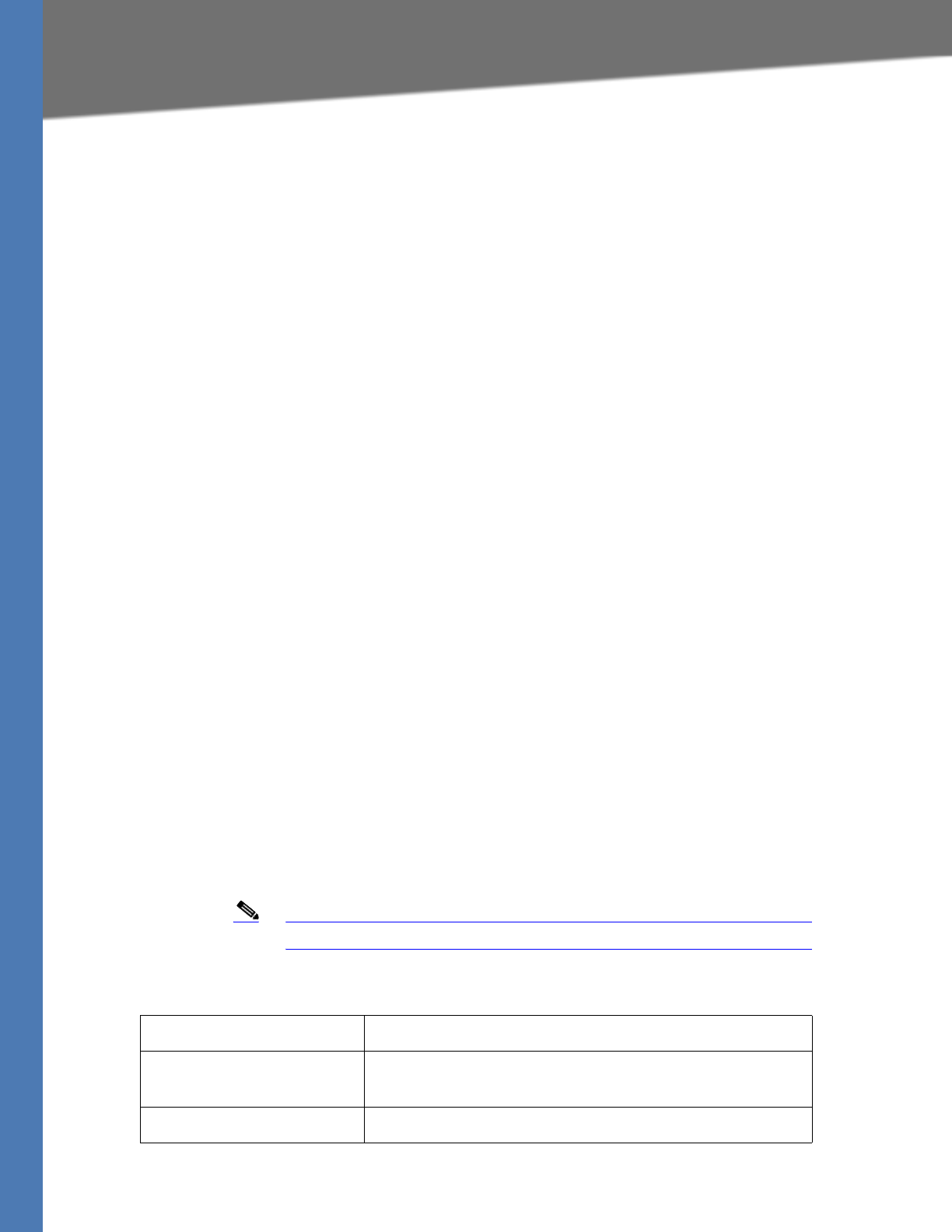
Linksys Voice System Administration Guide 53
Configuring Dial Plans
Configuring Phone Lines and Calling Routing Behavior
How the Dialed Digits are Processed
When a user lifts a handset or presses a speaker button, the following sequence of events
begins:
1. The phone begins collecting the dialed digits. The inter-digit timers starts tracking the time
that elapses between digits. For more information, see ”Setting the Timers for the Dial Plan,”
on page 59.
2. If the inter-digit timer value is reached, or if another terminating event occurs, the phone
compares the dialed digits with the PHONE (SYSTEM) dial plan (on the SPA9xx Telephone
Configuration > Ext N page, Dial Plan section). For more information, see ”Acceptance and
Transmission the Dialed Digits,” on page 56, ”Editing the System Dial Plan,” on page 57, and
”Entering a Phone Dial Plan,” on page 58.
NOTE: If a call is placed from a phone that is connected to a SPA9000 FXS port, the FXS port
dial plan applies. See ”Configuring a Line Interface for a SPA400 (PSTN or Voice Mail),” on
page 48.
3. If the phone dial plan allows the call to process, the dialed numbers are sent to the SPA9000.
4. The SPA9000 compares the dialed digits to the CALL ROUTING RULE (on the SPA9000 Voice >
SIP page, PBX Parameters section). For more information, see ”Configuring a Call Routing
Rule,” on page 63.
5. If the call routing rule allows the call to process, then the SPA9000 compares the dialed
digits to the LINE INTERFACE dial plan (on the SPA9000 Voice > Line N page, Dial Plan
section). For more information, see ”Entering the Line Interface Dial Plan,” on page 59.
6. The SPA9000 uses the information in the line dial plan to manipulate the number (for
example, to remove steering digits) and then transmits the number.
Digit Sequences
A dial plan contains a series of digit sequences, separated by the | character. The entire
collection of sequences is enclosed within parentheses. Each digit sequence within the dial
plan consists of a series of elements, which are individually matched to the keys that the user
presses. The sequence can include the elements that are listed in Table 4-2.
Note White space is ignored, but may be used for readability.
Table 4-2 Digit Sequences and Functions
Digit Sequence Function
0 1 2 3 4 5 6 7 8 9 0 * # Enter any of these characters to represent a key that the user
must press on the phone keypad.
xEnter x to represent any character on the phone keypad.

Linksys Voice System Administration Guide 54
Configuring Dial Plans
Configuring Phone Lines and Calling Routing Behavior
[sequence] Enter characters within square brackets to create a list of
accepted key presses. The user can press any one of the keys
in the list.
• Numeric range
For example, you would enter [2-9] to allow the user to
press any one digit from 2 through 9.
• Numeric range with other characters
For example, you would enter [35-8*] to allow the user to
press 3, 5, 6, 7, 8, or *.
.
(period)
Enter a period for element repetition. The dial plan accepts 0
or more entries of the digit. For example, 01. allows users to
enter 0, 01, 011, 0111, and so on.
<dialed:substituted> Use this format to indicate that certain dialed digits are
replaced by other characters when the sequence is
transmitted. The dialed digits can be zero or more characters.
EXAMPLE 1: <8:1650>xxxxxxx
When the user presses 8 followed by a seven-digit number,
the system automatically replaces the dialed 8 with 1650. If
the user dials 85550112, the system transmits
16505550112.
EXAMPLE 2: <:1>xxxxxxxxxx
In this example, no digits are replaced. When the user enters
a 10-digit string of numbers, the number 1 is added at the
beginning of the sequence. If the user dials 9725550112,
the system transmits 19725550112
,
(comma)
Enter a comma between digits to play an “outside line” dial
tone after a user-entered sequence.
EXAMPLE: 9, 1xxxxxxxxxx
An “outside line” dial tone is sounded after the user presses
9, and the tone continues until the user presses 1.
!
(exclamation point)
Enter an exclamation point to prohibit a dial sequence
pattern.
EXAMPLE: 1900xxxxxxx!
The system rejects any 11-digit sequence that begins with
1900.
*xx Enter an asterisk to allow the user to enter a 2-digit star code.
S0 Enter S0 to reduce the timer to 0 so that the dialed digits are
evaluated after 0 seconds.
For more information about modifying the timers for the
evaluation of dialed digits, see ”Setting the Timers for the
Dial Plan,” on page 59.
Digit Sequence Function

Linksys Voice System Administration Guide 55
Configuring Dial Plans
Configuring Phone Lines and Calling Routing Behavior
Digit Sequence Examples
The following examples show digit sequences that you can enter in a dial plan.
In a complete dial plan entry, sequences are separated by a pipe character (|), and the entire set
of sequences is enclosed within parentheses.
EXAMPLE: ( [1-8]xx | 9, xxxxxxx | 9, <:1>[2-9]xxxxxxxxx | 8, <:1212>xxxxxxx | 9, 1 [2-9]
xxxxxxxxx | 9, 1 900 xxxxxxx ! | 9, 011xxxxxx. | 0 | [49]11 )
• Extensions on your system
EXAMPLE: ( [1-8]xx | 9, xxxxxxx | 9, <:1>[2-9]xxxxxxxxx | 8, <:1212>xxxxxxx | 9, 1 [2-9]
xxxxxxxxx | 9, 1 900 xxxxxxx ! | 9, 011xxxxxx. | 0 | [49]11 )
[1-8]xx Allows a user dial any three-digit number that starts with the digits 1 through 8.
If your system uses four-digit extensions, you would instead enter the following string:
[1-8]xxx
• Local dialing with seven-digit number
EXAMPLE: ( [1-8]xx | 9, xxxxxxx | 9, <:1>[2-9]xxxxxxxxx | 8, <:1212>xxxxxxx | 9, 1 [2-9]
xxxxxxxxx | 9, 1 900 xxxxxxx ! | 9, 011xxxxxx. | 0 | [49]111)
9, xxxxxxx After a user presses 9, an external dial tone sounds. The user can enter any
seven-digit number, as in a local call.
• Local dialing with 3-digit area code and a 7-digit local number
EXAMPLE: ( [1-8]xx | 9, xxxxxxx | 9, <:1>[2-9]xxxxxxxxx | 8, <:1212>xxxxxxx | 9, 1 [2-9]
xxxxxxxxx | 9, 1 900 xxxxxxx ! | 9, 011xxxxxx. | 0 | [49]11 )
9, <:1>[2-9]xxxxxxxxx This example is useful where a local area code is required. After a
user presses 9, an external dial tone sounds. The user must enter a 10-digit number that
begins with a digit 2 through 9. The system automatically inserts the 1 prefix before
transmitting the number to the carrier.
• Local dialing with an automatically inserted 3-digit area code
EXAMPLE: ( [1-8]xx | 9, xxxxxxx | 9, <:1>[2-9]xxxxxxxxx | 8, <:1212>xxxxxxx | 9, 1 [2-9]
xxxxxxxxx | 9, 1 900 xxxxxxx ! | 9, 011xxxxxx. | 0 | [49]11 )
8, <:1212>xxxxxxx This is example is useful where a local area code is required by the
carrier but the majority of calls go to one area code. After the user presses 8, an external
dial tone sounds. The user can enter any seven-digit number. The system automatically
inserts the 1 prefix and the 212 area code before transmitting the number to the carrier.
• U.S. long distance dialing
EXAMPLE: ( [1-8]xx | 9, xxxxxxx | 9, <:1>[2-9]xxxxxxxxx | 8, <:1212>xxxxxxx | 9, 1 [2-9]
xxxxxxxxx | 9, 1 900 xxxxxxx ! | 9, 011xxxxxx. | 0 | [49]11 )
9, 1 [2-9] xxxxxxxxx After the user presses 9, an external dial tone sounds. The user can
enter any 11-digit number that starts with 1 and is followed by a digit 2 through 9.

Linksys Voice System Administration Guide 56
Configuring Dial Plans
Configuring Phone Lines and Calling Routing Behavior
• Blocked number
EXAMPLE: ( [1-8]xx | 9, xxxxxxx | 9, <:1>[2-9]xxxxxxxxx | 8, <:1212>xxxxxxx | 9, 1 [2-9]
xxxxxxxxx | 9, 1 900 xxxxxxx ! | 9, 011xxxxxx. | 0 | [49]11 )
9, 1 900 xxxxxxx ! This digit sequence is useful if you want to prevent users from dialing
numbers that are associated with high tolls or inappropriate content, such as 1-900
numbers in the U.S.. After the user press 9, an external dial tone sounds. If the user
enters an 11-digit number that starts with the digits 1900, the call is rejected.
• U.S. international dialing
EXAMPLE: ( [1-8]xx | 9, xxxxxxx | 9, <:1>[2-9]xxxxxxxxx | 8, <:1212>xxxxxxx | 9, 1 [2-9]
xxxxxxxxx | 9, 1 900 xxxxxxx ! | 9, 011xxxxxx. | 0 | [49]11 )
9, 011xxxxxx. After the user presses 9, an external dial tone sounds. The user can enter
any number that starts with 011, as in an international call from the U.S.
• Informational numbers
EXAMPLE: ( [1-8]xx | 9, xxxxxxx | 9, <:1>[2-9]xxxxxxxxx | 8, <:1212>xxxxxxx | 9, 1 [2-9]
xxxxxxxxx | 9, 1 900 xxxxxxx ! | 9, 011xxxxxx. | 0 | [49]11 )
0 | [49]11 This example includes two digit sequences, separated by the pipe character.
The first sequence allows a user to dial 0 for an operator. The second sequence allows
the user to enter 411 for local information or 911 for emergency services.
Acceptance and Transmission the Dialed Digits
When a user dials a series of digits, each sequence in the dial plan is tested as a possible match.
The matching sequences form a set of candidate digit sequences. As more digits are entered by
the user, the set of candidates diminishes until only one or none are valid. When a terminating
event occurs, the SPA9000 either accepts the user-dialed sequence and initiates a call, or else
rejects the sequence as invalid. The user hears the reorder (fast busy) tone if the dialed
sequence is invalid.
The following explains how terminating events are processed.
Terminating Event Processing
The dialed digits do not match any
sequence in the dial plan.
The number is rejected.
The dialed digits exactly match one
sequence in the dial plan.
• If the sequence is allowed by the dial
plan, the number is accepted and is
transmitted according to the dial
plan.
• If the sequence is blocked by the dial
plan, the number is rejected.
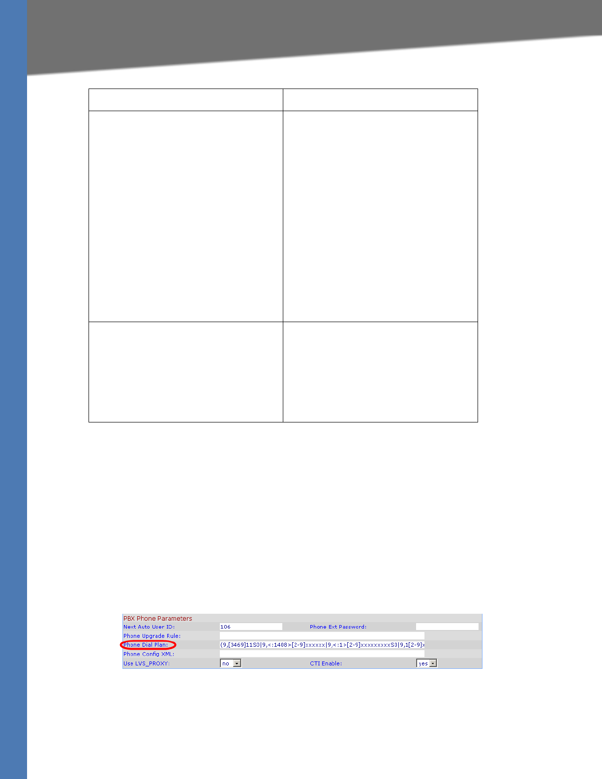
Linksys Voice System Administration Guide 57
Configuring Dial Plans
Configuring Phone Lines and Calling Routing Behavior
Editing the System Dial Plan
Follow this procedure to edit the system dial plan, which will be auto-provisioned to the first
extension of each phone.
1. Connect to the SPA9000 administration web server, and choose Admin access with
Advanced settings. (See ”Connecting to the SPA9000 Administration Web Server,” on
page 24.)
2. Click Voice tab > SIP.
3. Scroll down to the PBX Phone Parameters section.
SPA9000 Voice > SIP: PBX Phone Parameters
4. Enter the digit sequences in the Dial Plan field. For more information and examples, see
”Digit Sequences and Functions,” on page 53.
A timeout occurs. The number is rejected if the dialed
digits are not matched to a digit
sequence in the dial plan within the time
specified by the applicable interdigit
timer.
• The Interdigit Long Timer applies
when the dialed digits do not match
any digit sequence in the dial plan.
The default value is 10 seconds.
• The Interdigit Short Timer applies
when the dialed digits match one or
more candidate sequences in the dial
plan. The default value is 3 seconds.
For more information, see ”Setting the
Timers for the Dial Plan,” on page 59.
The user presses the # key or the dial
softkey on the phone display.
• If the sequence is complete and is
allowed by the dial plan, the number
is accepted and is transmitted
according to the dial plan.
• If the sequence is incomplete or is
blocked by the dial plan, the number
is rejected.
Terminating Event Processing

Linksys Voice System Administration Guide 58
Configuring Dial Plans
Configuring Phone Lines and Calling Routing Behavior
Note Separate each digit sequence with a pipe character, and enclose the
entire set of digit sequences within parentheses. Refer to the following
example:
(9,8<:1408>[2-9]xxxxxx | 9,8,1[2-9]xxxxxxxxx | 9,8,011xx. | 9,8,xx.|[1-8]xx)
5. Click Submit All Changes. The phones reboot.
6. Verify that you can successfully complete a call using each digit sequence that you entered
in the dial plan.
Note If you hear a reorder (fast busy) tone, you need to review your entries
and modify the dial plan appropriately. See ”Digit Sequences,” on
page 53.
Entering a Phone Dial Plan
The phone dial plan is automatically updated when the system phone dial plan is modified.
There are special cases where it is required to enter the phone dial plan directly on the phone.
Follow the procedure below to enter a dial plan for a particular extension on a client station in
the following cases:
• The phone is outside the SPA9000 multicast domain (e.g. when the phone is connected
to the SPA9000 via a VPN connection).
• For additional extensions on an existing phone (the system wide phone dial plan is
propagated only to extension 1 of all phones).
1. Connect to the SPA9000 administration web server, and choose Admin access with
Advanced settings. (See ”Connecting to the SPA9000 Administration Web Server,” on
page 24.)
2. Click the PBX Status link near the top right corner or lower left corner of the page, to view
the list of client stations.
3. Click the hyperlink in the IP Address column for the first phone that you want to configure.
The telephone configuration page appears in a separate browser window.
4. Click the Ext 1 tab, or the tab for the extension that you want to configure.
5. Scroll down to the Dial Plan section.
6. Enter the digit sequences in the Dial Plan field.
NOTE:
• The default (US-based) system-wide dial plan appears automatically in the field. You can
delete digit sequences, add digit sequences, or replace the entire dial plan with a new

Linksys Voice System Administration Guide 59
Configuring Dial Plans
Configuring Phone Lines and Calling Routing Behavior
dial plan. For more information and examples, see ”Digit Sequences and Functions,” on
page 53.
• Separate each digit sequence with a pipe character, and enclose the entire set of digit
sequences within parentheses. Refer to the following example:
(9,8<:1408>[2-9]xxxxxx | 9,8,1[2-9]xxxxxxxxx | 9,8,011xx. | 9,8,xx.|[1-8]xx)
7. Click Submit All Changes. The phone reboots.
8. If you need to configure a dial plan for any other extensions on the phone (depending on
the model), click the appropriate Extension tab, enter the dial plan, and submit the changes.
9. Click the browser’s Back button to return to the list of phones.
10. Repeat this procedure for each client station that needs a unique dial plan.
11. Verify that you can successfully complete a call using each digit sequence that you entered
in the dial plan.
Note If you hear a reorder (fast busy) tone, you need to review your entries
and modify the dial plan appropriately. See ”Digit Sequences,” on
page 53.
Entering the Line Interface Dial Plan
This dial plan is used to strip steering digits from a dialed number before it is transmitted out to
the carrier.
1. Connect to the SPA9000 administration web server, and choose Admin access with
Advanced settings. (See ”Connecting to the SPA9000 Administration Web Server,” on
page 24.)
2. Click Voice tab > Line N, where N represents the line interface number.
3. Scroll down to the Dial Plan section.
4. Enter the digit sequences in the Dial Plan field.
5. Click Submit All Changes.
Setting the Timers for the Dial Plan
The system uses dial plan timers to determine when a user’s entry (or a null entry) is evaluated.
You can modify the timers for an entire dial plan or for individual sequences within a dial plan.
There are three types of control timers:
•”Dial Plan Timer (Off-Hook Timer),” on page 60
•”Interdigit Long Timer (Incomplete Entry Timer),” on page 61
•”Interdigit Short Timer (Complete Entry Timer),” on page 61

Linksys Voice System Administration Guide 60
Configuring Dial Plans
Configuring Phone Lines and Calling Routing Behavior
Dial Plan Timer (Off-Hook Timer)
You can think of the Dial Plan Timer as “the off-hook timer.” This timer starts counting when the
phone goes off hook. If no digits are dialed within the specified number of seconds, the timer
expires and the null entry is evaluated. Unless you have a special dial plan string to allow a null
entry, the call is rejected. The default value is 5.
Syntax for the Dial Plan Timer
SYNTAX: (Ps<:n> | dial plan )
•s: The number of seconds; if no number is entered after P, the default timer of 5 seconds
applies.
•n: (optional): The number to transmit automatically when the timer expires; you can
enter an extension number or a DID number. No wildcard characters are allowed
because the number will be transmitted as shown. If you omit the number substitution,
<:n>, then the user hears a reorder (fast busy) tone after the specified number of
seconds.
Examples for the Dial Plan Timer
• Allow more time for users to start dialing after taking a phone off hook.
EXAMPLE: (P9 | (9,8<:1408>[2-9]xxxxxx | 9,8,1[2-9]xxxxxxxxx | 9,8,011xx. | 9,8,xx.|[1-8]xx)
P9 After taking a phone off hook, a user has 9 seconds to begin dialing. If no digits are
pressed within 9 seconds, the user hears a reorder (fast busy) tone. By setting a longer
timer, you allow more time for users to enter the digits.
• Create a hotline for all sequences on the System Dial Plan
EXAMPLE: (P9<:23> | (9,8<:1408>[2-9]xxxxxx | 9,8,1[2-9]xxxxxxxxx | 9,8,011xx. |
9,8,xx.|[1-8]xx)
P9<:23> After taking the phone off hook, a user has 9 seconds to begin dialing. If no
digits are pressed within 9 seconds, the call is transmitted automatically to extension 23.
• Create a hotline on a line button for an extension
EXAMPLE: ( P0 <:1000>)
With the timer set to 0 seconds, the call is transmitted automatically to the specified
extension when the phone goes off hook. Enter this sequence in the Phone Dial Plan for
Ext 2 or higher on a client station.
Setting the Dial Plan Timer for the System Dial Plan
Follow the procedure ”Editing the System Dial Plan,” on page 57.

Linksys Voice System Administration Guide 61
Configuring Dial Plans
Configuring Phone Lines and Calling Routing Behavior
Interdigit Long Timer (Incomplete Entry Timer)
You can think of this timer as the “incomplete entry” timer. This timer measures the interval
between dialed digits. It applies as long as the dialed digits do not match any digit sequences
in the dial plan. Unless the user enters another digit within the specified number of seconds,
the entry is evaluated as incomplete, and the call is rejected. The default value is 10 seconds.
Note This section explains how to edit a timer as part of a dial plan.
Alternatively, you can modify the Control Timer that controls the default
interdigit timers for all calls. See ”Editing the Control Timers for the
Default Interdigit Values,” on page 62.
Syntax for the Interdigit Long Timer
SYNTAX: L:s, ( dial plan )
•s: The number of seconds; if no number is entered after L:, the default timer of 5
seconds applies.
• Note that the timer sequence appears to the left of the initial parenthesis for the dial
plan.
Example for the Interdigit Long Timer
EXAMPLE: L:15, (9,8<:1408>[2-9]xxxxxx | 9,8,1[2-9]xxxxxxxxx | 9,8,011xx. | 9,8,xx.|[1-8]xx)
L:15, This dial plan allows the user to pause for up to 15 seconds between digits before the
Interdigit Long Timer expires. This setting is especially helpful to users such as sales people,
who are reading the numbers from business cards and other printed materials while dialing.
Setting the Interdigit Long Timer for the System Dial Plan
Follow the procedure ”Editing the System Dial Plan,” on page 57.
Interdigit Short Timer (Complete Entry Timer)
You can think of this timer as the “complete entry” timer. This timer measures the interval
between dialed digits. It applies when the dialed digits match at least one digit sequence in the
dial plan. Unless the user enters another digit within the specified number of seconds, the entry
is evaluated. If it is valid, the call proceeds. If it is invalid, the call is rejected. The default value is
3 seconds.
Note This section explains how to edit a timer as part of a dial plan.
Alternatively, you can modify the Control Timer that controls the default
interdigit timers for all calls. See ”Editing the Control Timers for the
Default Interdigit Values,” on page 62.

Linksys Voice System Administration Guide 62
Configuring Dial Plans
Configuring Phone Lines and Calling Routing Behavior
Syntax for the Interdigit Short Timer
•SYNTAX 1: S:s, ( dial plan )
Use this syntax to apply the new setting to the entire dial plan within the parentheses.
•SYNTAX 2: sequence Ss
Use this syntax to apply the new setting to a particular dialing sequence.
–s: The number of seconds; if no number is entered after S, the default timer of 5
seconds applies.
Examples for the Interdigit Short Timer
• Set the timer for the entire dial plan.
EXAMPLE: S:6, (9,8<:1408>[2-9]xxxxxx | 9,8,1[2-9]xxxxxxxxx | 9,8,011xx. | 9,8,xx.|[1-8]xx)
S:6, While entering a number with the phone off hook, a user can pause for up to 15
seconds between digits before the Interdigit Short Timer expires. This setting is
especially helpful to users such as sales people, who are reading the numbers from
business cards and other printed materials while dialing.
• Set an instant timer for a particular sequence within the dial plan.
EXAMPLE: (9,8<:1408>[2-9]xxxxxx | 9,8,1[2-9]xxxxxxxxxS0 | 9,8,011xx. | 9,8,xx.|[1-8]xx)
9,8,1[2-9]xxxxxxxxxS0 With the timer set to 0, the call is transmitted automatically when
the user dials the final digit in the sequence.
Setting the Interdigit Long Timer for the System Dial Plan
Follow the procedure ”Editing the System Dial Plan,” on page 57.
Setting the Interdigit Long Timer for the Phone Dial Plan
Follow the procedure ”Entering a Phone Dial Plan,” on page 58.
Editing the Control Timers for the Default Interdigit Values
Note Use the following procedure to edit the default timer settings for all
calls. If you need to edit a timer setting only for a particular digit
sequence or type of call, you can edit the dial plan. See Table 4-2, ‘Digit
Sequences and Functions,” on page 53.
1. Connect to the SPA9000 administration web server, and choose Admin access with
Advanced settings. (See ”Connecting to the SPA9000 Administration Web Server,” on
page 24.)
2. Click Voice tab > Regional.
3. Scroll down to the Control Timer Values section.
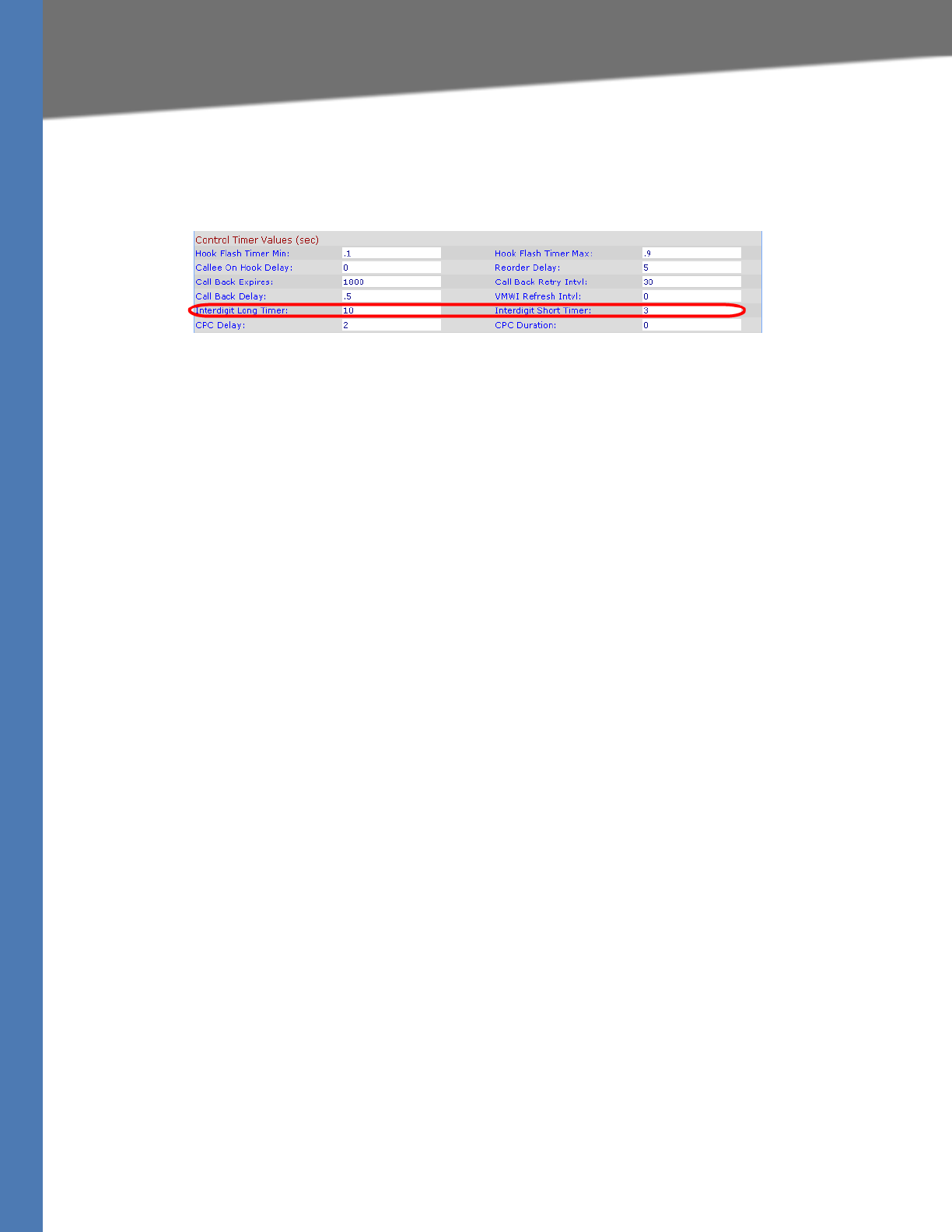
Linksys Voice System Administration Guide 63
Managing the Line Selection for Outbound Calls
Configuring Phone Lines and Calling Routing Behavior
4. Enter the desired values in the Interdigit Long Timer field and the Interdigit Short Timer field.
Refer to the definitions at the beginning of this section.
SPA9000 Voice > Regional: Control Timer Values
Managing the Line Selection for Outbound Calls
When a user places an outbound call, the SPA9000 chooses a line based on the group
membership of the station and the Call Routing Rule for the line interface. You can configure
the settings to route calls through particular lines, based on factors such as the dialed number,
the destination, or the corporate identity that you want to represent.
This section includes the following topics:
•”Line Availability,” on page 63
•”Configuring a Call Routing Rule,” on page 63
•”Entering a Call Routing Rule,” on page 65
Line Availability
The SPA9000 considers a line to be available for an outgoing call if the following conditions are
met:
• The line is enabled in the configuration and is functioning. See ”Configuring Line
Interfaces on the SPA9000,” on page 46.
• The line is authorized by the Call Routing Rule for the dialed number. See”Configuring a
Call Routing Rule,” on page 63.
• The line has capacity to take more calls. See ”Configuring Call Capacity for a Line
Interface,” on page 51.
• The Dial Plan for this line allows the dialed number. See ”Configuring Dial Plans,” on
page 52.
Configuring a Call Routing Rule
A Call Routing Rule is a special dial plan that specifies the lines that can be used to transmit a
dialed number. The same number pattern can apply to more than one line.
SYNTAX: ( <:Lw,x,y,z>number-pattern | <:Lw,x,y,z>number-pattern | <:Lw,x,y,z>number-pattern |
<:Lw,x,y,z>number-pattern )
•L: A signifier for “Line”

Linksys Voice System Administration Guide 64
Managing the Line Selection for Outbound Calls
Configuring Phone Lines and Calling Routing Behavior
•w, x, y, z: The number of the line interface (L1 for Line 1, L2 for Line 2, and so on)
•number-pattern: The dialed sequence that can use the specified lines
• Other elements:
– Enclose the entire call routing rule in parentheses.
– Use a comma to separate each digit sequence within a number-pattern.
– Use a pipe character (|) to separate each call routing rule.
Note The Call Routing rules use the same digit sequences as the Dial Plan
rules. See Table 4-2, ‘Digit Sequences and Functions,” on page 53.
• Any line interface can be used for allowed digit sequences
EXAMPLE: (<:L1,2,3,4>9xx.)
Any line interface can be used for any dialed sequence that begins with 9 and includes
at least two additional numbers. The SPA9000 chooses an available line from the list,
proceeding in the listed order. See Table 4-2, ‘Digit Sequences and Functions,” on
page 63.
• Different line interfaces for U.S., international, and 1-800 numbers
EXAMPLE: (<:L1,2>9xx. | <:L3>011852xx. | <:L4>1800xxxxxxx )
This example has three parts:
–<:L1,2>9xx. Line 1 and Line 2 can be used if the sequence starts with 9 and includes
at least two additional digits.
–<:L3>011852xx. Line 3 can be used if the sequence starts with 011852 and includes
at least two additional digits.
–<:L4>1800xxxxxxx Line 4 can be used if the sequence starts with 1800 and
includes at least seven additional digits.
• Separate lines for long distance and local calling
EXAMPLE: (<:L1>9xx. | <:L2>8xx.)
Line 1 is used for any dialed sequence that starts with 9. Line 2 is used for any dialed
sequence that starts with 8. This call routing rule is effective if users understand that 9 is
the steering digit for long distance (with Line 1 configured for the ITSP and its
inexpensive long distance service) and that 8 is the steering digit for local calls (with
Line 2 configured for a SPA400 that has local phone lines connected).
• Wildcard characters
EXAMPLE: (<:L1>51*,577?)

Linksys Voice System Administration Guide 65
Managing Caller ID Settings for Outgoing Calls
Configuring Phone Lines and Calling Routing Behavior
In this example, Line 1 can be used when either of the following number patterns is
dialed:
– The user dials a number that starts with 51, followed by any other characters.
– The user dials any four-digit number starting with 577.
Entering a Call Routing Rule
1. Connect to the SPA9000 administration web server, and choose Admin access with
Advanced settings. (See ”Connecting to the SPA9000 Administration Web Server,” on
page 24.)
2. Click Voice tab > SIP.
3. Scroll down to the PBX Parameters section.
4. In the Call Routing Rule field, enter the rule that you want to apply
5. Click Submit All Changes.
6. To verify your progress, place a call to a phone that has caller ID, and confirm that the
expected number appears.
Managing Caller ID Settings for Outgoing Calls
By default, outgoing calls through an ITSP line are identified by the User ID (usually the phone
number) and Display Name of the selected line interface. Alternatively, you can map a DID
number to a phone extension so that all outbound calls from that extension will identify the
caller by the DID number and the assigned phone display name. (See ”Supporting Multiple DID
Numbers Per Line Interface,” on page 68.)
Note Caller ID for a PSTN line is controlled by the phone company. Caller ID
through an ITSP line should work as described, but if not, contact your
ITSP to see what is allowed for caller ID configuration.
1. Connect to the SPA9000 administration web server, and choose Admin access with
Advanced settings. (See ”Connecting to the SPA9000 Administration Web Server,” on
page 24.)
2. Click Voice > Line N, where N represents the line interface number.
3. Scroll down to the Subscriber Information section.
4. Enter the desired display name for Caller ID in the Display Name field.
5. Click Submit All Changes.

Linksys Voice System Administration Guide 66
Managing Inbound Calls with the Contact List
Configuring Phone Lines and Calling Routing Behavior
Managing Inbound Calls with the Contact List
You can use the Contact List to route inbound calls to the Auto Attendant, to a receptionist, to a
client station, to a group of stations, or to a combination of these.
•”Routing an Inbound Call to the Auto Attendant,” on page 66
•”Routing an Inbound Call to a Receptionist or Client Stations,” on page 66
•”Example Contact List Rules,” on page 66
•”Entering a Contact List Rule,” on page 70
Routing an Inbound Call to the Auto Attendant
By default, all inbound calls are routed to the Auto Attendant (aa). This automated system
answers inbound calls by playing pre-recorded voice message that asks the caller to enter the
desired extension. If you want only the Auto Attendant to receive a call, keep the default
setting, aa, in the Contact List field on the Voice > Line N page, Subscriber Information section, for
each line interface. For more information, see Chapter 7, "Configuring the LVS Auto-Attendant.".
Routing an Inbound Call to a Receptionist or Client Stations
You can route an inbound call to a receptionist or to client stations by using a Contact List. You
specify the Contact List for each line interface (Line 1, Line 2, Line 3, Line 4). For example, if
Line 1 is configured for an ITSP account, and a call is placed to a Direct Inward Dialing (DID)
number for that account, then the call is routed to the Contact List that is specified on the Line
1 configuration page. Likewise, if Line 2 is configured for a SPA400 that has PSTN lines attached,
and a call is placed to the associated PSTN phone number, then the call is routed as specified in
the Voice > Line page, Subscriber Information section, Contact List field.
Example Contact List Rules
The following examples show rules that you can enter to route incoming calls.
Note The SPA9000 alerts all registered clients stations if * is used in the
Contact List (SPA9000 Voice > Line N page > Subscriber Information
section).
• Routing calls to a receptionist
EXAMPLE: 100
An incoming call to any DID number on this line interface causes station 100 to ring. The
receptionist answers the call. If the call is not answered, it automatically goes to the
voice mailbox for station 100, assuming that voice mail is configured.
• Routing calls simultaneously to two or more stations
EXAMPLE: 100, 104

Linksys Voice System Administration Guide 67
Managing Inbound Calls with the Contact List
Configuring Phone Lines and Calling Routing Behavior
An incoming call to any DID number on this line interface causes station 100 and station
104 to ring. Either station can answer the call.
NOTE: The list of extension numbers may include * to represent multiple wildcard
characters or ? to represent a single wildcard character. For example, 10? represents all
stations numbered 100 through 109.
• Special routing for different DID numbers
EXAMPLE: 9725550155:100|9725550156:101, 102
An incoming call to 972-555-0155 causes station 100 to ring. An incoming call to 972-
555-0156 causes station 101 and station 102 to ring simultaneously.
Note In this example, the rules are separated by a pipe character (|) to indicate
an “or” condition.
• Routing calls to a station and forwarding unanswered calls to voice mail
EXAMPLE 1: 5300, cfwd=vm25300
An incoming call through this line interface causes station 5300 to ring. If there is no
answer, the call is forwarded to the voice mail server on line interface 2, mailbox number
5300. The time interval is determined by the value Cfwd No Ans Delay field, which is
located below the Contact List field on the Voice > Line page. The default value is 20
seconds.
EXAMPLE 2: 4085550122:5001|4085550123:5000,cfwd=aa
An incoming call to 408-555-0122 causes station 5001 to ring. An incoming call to 408-
555-0123 causes station 5000 to ring. If station 5000 does not answer its call, the call is
forwarded to the Auto Attendant. The time interval is determined by the value Cfwd No
Ans Delay field, which is located below the Contact List field. The default value is 20
seconds.
• Routing a call by ringing stations randomly
EXAMPLE: 530?,hunt=ra;10;2,cfwd=vm25404
An incoming call through this line interface causes one station in the group 5300
through 5309 to ring. The station is chosen randomly (ra). After 10 seconds, if the call is
unanswered, then another station is chosen randomly from the remaining stations. The
system cycles through the list two times. If the call is unanswered, it is forwarded to the
voice mail server on line interface 2, mailbox 5404.
SYNTAX: hunt=algo;interval;max, cfwd=target
–algo: The order to ring the stations
restart (re)—Always start from beginning of the list
next (ne)—Start from the next on the list to the last station that rings

Linksys Voice System Administration Guide 68
Managing Inbound Calls with the Contact List
Configuring Phone Lines and Calling Routing Behavior
random (ra)—Order is randomized for each call
–interval: The number of seconds to ring each station
–max: The total time in seconds or the total number of cycles to elapse before the call
is rejected or forwarded to the target. If max is less than interval, it is interpreted as
the number of cycles. If max is 0, hunting goes on indefinitely until the caller hangs
up or some one answers the call.
NOTE: You also can create a hunt group that acts as a separate extension within the
system. For more information, see ”Managing Inbound Calls with Hunt Groups,” on
page 73.
Supporting Multiple DID Numbers Per Line Interface
An ITSP can provide a block of DID numbers, for example with a main number of 4085553000,
and additional DID numbers from 4085553001–4084443009. The ITSP can identify the local
client stations to which an external incoming call should be routed. Linksys recommends
including this information in the TO header of the incoming INVITE while the request-URI is
addressed to the line interface user-id. In the INVITE, the ITSP indicates the DID number in the
TO header user-id field.
EXAMPLE SIP Header 1:
INVITE sip:4089993000@itsp1.com SIP/2.0
To: <sip:4089993003@itsp1.com>
Alternatively, the DID number can be indicated as a parameter in the TO header with a
configurable parameter name, such as didn.
EXAMPLE SIP Header 2:
INVITE sip:4089993000@itsp1.com SIP/2.0
To: <sip:4089993000@itsp1.com>;didn=4089993003
You can identify the field to use for the DID number and the parameter name on the Voice > SIP
page, PBX Parameters section, SIP DIDN and SIP DIDN Param Name fields. For the first example
above, these two fields are ignored; for the second example, SIP DIDN is set to TO Param and
SIP DIDN Param Name is set to didn.
The Contact List is used to route the calls to a client station based on DID numbers that are
embedded in the INVITE message.
EXAMPLE Contact List Rule:
4089993000:aa|4089993001:3001|4089993002:3002|…|4089993009:3009
Linksys Voice System Administration Guide 69
Managing Inbound Calls with the Contact List
Configuring Phone Lines and Calling Routing Behavior
An incoming call to the main number is answered by the Auto-Attendant, while calls to the
other nine DID numbers are routed to dedicated private extensions.
Supporting Direct Inward Dialing to Phone Extensions
Direct Inward Dialing allows the external users to dial directly any phone extension in the LVS
system, without passing through the Auto Attendant or the receptionist.
Before proceeding with the configuration you need to have the full correspondence between
the external (DID) number and the extension number. Table 4-3 provides an example.
Table 4-3 DID-to-Extension Mapping Example
NOTE:
• Direct Inward Dialing requires network support for SIP trunking DID.
• It is important that the DID number format match exactly the format of the number
signaled in the SIP trunk.
• Please check with your Service Provider to confirm the availability of this feature and the
correct DID number format, before proceeding with this configuration.
SYNTAX:
<DIDn1>:+<Extn1>|<DIDn2>:+<Extn2>|<DIDn3>:+<Extn3>|<DIDn4>:+<Extn4>|<DIDn5>:
+<Extn5>|<DIDn6>:+<Extn6>|<DIDn7>:+<Extn7>|<DIDn8>:+<Extn8>|<DIDn9>:+<Extn9>|
<DIDn10>:+<Extn10>|<DIDn11>:+<Extn11>|<DIDn12>:+<Extn12>|<DIDn13>:+<Extn13>|
<DIDn14>:+<Extn14>|<DIDn15>:+<Extn15>|<DIDn16>:+<Extn16>|<default_route>
EXAMPLE:
4085555550:aa|4085555551:+101|4085555552:+102|4085555553:+103|4085555554:+104|408555565
0:+500|
• Enter a plus (+) or a minus (-) before the extension number to achieve the desired results
for caller ID and call routing:
–+ <Extn1> The extension will be alerted when there is an incoming call to the DID
number, and the DID number will be used as the local user-ID in outbound SIP
requests, along with the display-name of the extension.
DID number Extension number User
408-555-5550 aa Auto Attendant
408-555-5551 101 User 1
408-555-5552 102 User 2
408-555-5553 103 User 3
408-555-5554 104 User 4
408-555-5650 500 Support (hunt) group
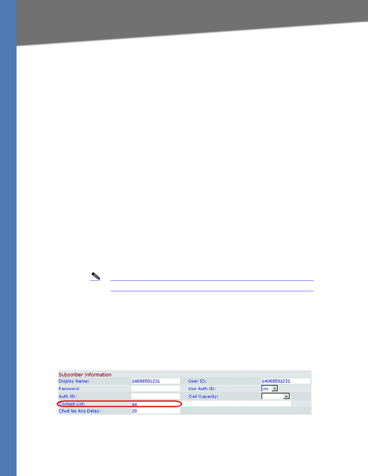
Linksys Voice System Administration Guide 70
Managing Inbound Calls with the Contact List
Configuring Phone Lines and Calling Routing Behavior
–- <Extn1> The extension will not be alerted when there is an incoming call to the DID
number. However, the DID number will be used as the local user-ID in outbound SIP
requests, along with the display-name of the extension. DIDn#: DID number,
matching the format of the number signaled in the SIP trunk
• Extn#: Target extension number or a for Auto Attendant
• Default route: The default route (extension, hunt group or Auto Attendant) to be used in
case the incoming target number does not match any of the DID numbers in the
contact list with the format described in the sections above.
• Call forwarding: Optionally, add call forward information to the Contact List to specify
how unanswered calls are handled.
NOTE: It is useful to add call forward information to ensure that calls are answered when
the designated phone is unstaffed, as may be the case during lunch time or after hours.
In this case, if the call is not answered within a specified time, the call is routed to
another phone or to the Auto Attendant.
SYNTAX:
<DIDn1>:+<Extn1>,cfwd=<target>|<DIDn2>:+<Extn2>,cfwd=<target>|<DIDn3>:+<Extn3>
,cfwd=<target>
EXAMPLE:
4085555550:aa|4085555551:+101,cfwd=aa|4085555552:+102|4085555553:+103|4085555554:
+104|4085555650:+500|
Entering a Contact List Rule
Note The maximum length of the <Contact List> parameter is 383 characters.
1. Connect to the SPA9000 administration web server, and choose Admin access with
Advanced settings. (See ”Connecting to the SPA9000 Administration Web Server,” on
page 24.)
2. Click Voice tab > Line N, where N represents the line interface number.
3. Scroll down to the Subscriber Information section.
SPA9000 Voice > Line: Subscriber Information
4. Enter the desired rules in the Contact List field. For more information, see ”Example Contact
List Rules,” on page 66 and ”Entering a Contact List Rule,” on page 70.
Linksys Voice System Administration Guide 71
Call Forwarding Support on SPA9000
Configuring Phone Lines and Calling Routing Behavior
5. If you included a call forward rule, modify the Cfwd No Ans Delay parameter to specify the
number of seconds that elapse before a call is considered to be unanswered.
6. Click Submit All Changes. The SPA9000 reboots.
7. To verify your progress, make an inbound call and verify that the call is handled as you intended.
Call Forwarding Support on SPA9000
SPA9000 supports the call forward scenarios listed in the following table.
SPA9000 supports call forward by client station:
• unconditionally
•when busy
•on no answer
Note When an incoming call from the ITSP is forked to multiple client stations,
the SPA9000 does not honor the 3xx response returned by any of the
client stations. If you wish the call to be forwarded to voicemail or
another client station when it is not picked up, you can specify the
optional “cfwd=target” syntax in the Contact List.
Called
Party
Caller Forward Target Remarks
Client
station
Client
station
Client station Proxy only; no direct involvement
Client
station
Client
station
External Very similar to calling external number
Client
station
External Client station ACKs the 302 from called party. Then
INVITEs the target. NOTE: If the original
INVITE is forked to more than one client
station, call forward is not performed.
Client
station
External External ACKs the 302 from called party. Sends
200 to caller, then blind REFERs caller to
target. NOTE: If the original INVITE is
forked to more than one client station,
call forward is not performed
External Client
station
External ACKs the 302 from called party, then
INVITEs the target

Linksys Voice System Administration Guide 72
Call Transfer Support on SPA9000
Configuring Phone Lines and Calling Routing Behavior
Call Transfer Support on SPA9000
•”Call Forward Bridge Mode,” on page 72
•”Call Transfer Bridge Mode,” on page 72
Call Forward Bridge Mode
The normal way of performing the call forwarding operation is for the SPA9000 to send a (blind)
SIP REFER to the calling device to let it contact the target number directly. It then drops out of
the call completely. This requires the calling device to understand the SIP signaling involved
and the operation permitted by the underlying service provider. The SPA400 cannot handle this
operation.
With bridging, the SPA9000 maintains two separate call legs throughout the call: one with the
caller and one with the call forward target. The two call peers connect only with the SPA9000,
while the SPA9000 acts as a proxy for the RTP packets exchanged between the two parties.
On the Voice > Line N page, Proxy and Registration section, the CWFD Bridge Mode field has two
possible values:
• none—Do not bridge forwarded calls (use the normal REFER method)
• all—Bridge all forwarded calls
Call Transfer Bridge Mode
The normal way of performing this operation is for the SPA9000 to send a SIP REFER method to
the calling device to let it contact the transfer target directly. The SPA9000 then drops out of the
call completely. This requires the calling device (the transferee) and the target device to
understand the SIP signaling involved and the operation permitted by the underlying service
providers. Note that the call legs with transferee and the transfer target might be with different
ITSP. The SPA400, for instance, cannot handle this operation.
With bridging, the SPA9000 maintains two separate call legs throughout the call: one with the
transferred call and one with the transfer target. The two call peers connect only with the
SPA9000, while the SPA9000 acts as a proxy for the RTP packets exchanged between the two
parties.
On the Voice > Line N page, Proxy and Registration section, the XFER Bridge Mode field has three
possible values:
• none —Do not bridge call transfer (use the normal REFER method)
• all —Bridge all call transfer
• all except same line—Bridge call transfer only if it is between two different line
interfaces

Linksys Voice System Administration Guide 73
Managing Inbound Calls with Hunt Groups
Configuring Phone Lines and Calling Routing Behavior
Managing Inbound Calls with Hunt Groups
A Hunt Group is a group of client stations that are treated as one extension for the purpose of
managing inbound calls. The client stations in the hunt group can be alerted simultaneously or
sequentially. The first client station to pick up the call establishes a private connection to the
caller.
You can configure two types of Hunt Groups:
•”Hunt Group that Rings All Stations Simultaneously,” on page 73
•”Hunt Group that Rings Stations Individually,” on page 75
Note Compare a Shared Line Appearance to a Hunt Group. A Hunt Group may
ring several stations simultaneously, but only one station can answer
and manage the call. A Shared Line Appearance also rings multiple lines
simultaneously but allows multiple stations to share and manage the
call. For more information, see ”Managing Inbound Calls with Shared Line
Appearances,” on page 77.
Hunt Group that Rings All Stations Simultaneously
You can create a hunt group that simultaneously rings all stations in the group. Optionally, you
can assign a name to the group or use wildcard characters to create the list of stations in the
group.
Syntax for a “Ring All Stations” Hunt Group Rule
The basic syntax for this type of group is shown below. Optionally, you can assign a name to the
group.
SYNTAX: ext-in:name=groupname,hunt-list
•ext-in (required): The extension number that users dial to contact this group
•name (optional): The name of the group, which appears in the Corporate Directory on
the phones
•hunt-list (required): The station numbers that participate in this group, separated by
commas
NOTE: To create multiple groups, separate the hunt group rules by typing the pipe
character: |
Examples of “Ring All Stations” Hunt Group Rules
• Contacting a group of stations simultaneously
EXAMPLE: 500:101,102,103
This hunt group is assigned a number (500:). The group includes three stations
(101,102,103). A call to extension 500 rings all three stations simultaneously.

Linksys Voice System Administration Guide 74
Managing Inbound Calls with Hunt Groups
Configuring Phone Lines and Calling Routing Behavior
• Creating a named hunt group
EXAMPLE: 500:name=TechSupport,101,102,103
This hunt group is assigned a number (500:) and a name (name=TechSupport). The group
includes three stations (101,102,103). A call to extension 500 rings all three stations
simultaneously.
• Wildcards in Hunt List
EXAMPLE 1: 500:10?
In this example, the ? symbol is a wildcard character that represent any single digit. A
call to extension 500 simultaneously rings all stations 100 through 109.
EXAMPLE 2: 500:1*
In this example, the * symbol is a wildcard character that represents any number of
digits. A call to extension 500 simultaneously rings all stations that begins with the
number 1.
EXAMPLE: 500:name=TechSupport,1*
In this example, the group has a name, Tech Support. The * symbol is a wildcard
character that represents any number of digits. A call to extension 500 simultaneously
rings all stations that begins with the number 1.
• Creating multiple hunt groups
EXAMPLE: 500:name=TechSupport,101,102,103|600:name=AccountSupport,2*|
Two hunt groups are created and are assigned names. A call to extension 500
simultaneously rings stations 101, 102, and 103. A call to extension 600 simultaneously
rings all stations that begin with the number 2.
Creating a Hunt Group to Ring All Stations
1. Connect to the SPA9000 administration web server, and choose Admin access with
Advanced settings. (See ”Connecting to the SPA9000 Administration Web Server,” on
page 24.)
2. Click Voice tab > SIP.
3. Scroll down to the PBX Parameters section.
4. In the Hunt Groups field, type your hunt group rule. See “Syntax for a “Ring All Stations” Hunt
Group Rule” on page_61 and “Examples of “Ring All Stations” Hunt Group Rules” on
page_61.
5. Click Submit All Changes. The phones reboot.
6. To verify the settings, place a call to the new group line. Verify that all of the listed
extensions ring simultaneously.

Linksys Voice System Administration Guide 75
Managing Inbound Calls with Hunt Groups
Configuring Phone Lines and Calling Routing Behavior
Hunt Group that Rings Stations Individually
You can create a hunt group that rings the stations individually, in sequential order or random
order. You need to set the ring interval and the maximum number of cycles or seconds to occur
before a call is transferred to voice mail.
Syntax for a “Ring Individual Stations” Hunt Group Rule
The syntax for a “ring individual stations” hunt group rule is shown below. Optionally, you can
assign a name to the group.
SYNTAX: ext-in:name=groupname,hunt-list,type=algo;ring-interval;max,cfwd=ext-fwd
•ext-in (required): The extension number that users dial to contact this group
•name (optional): The name of the group, which appears in the Corporate Directory on
the phones
•hunt-list (required): The station numbers that participate in this group, separated by
commas
•type (required to ring individual stations): The type of routing among the stations in the
group
–re (sequentially from the beginning): Every incoming call is routed to the first station
in the list. If the call is unanswered, it cycles through the stations in the listed order.
The syntax is hunt=re.
–ne (sequentially from the next station): An incoming call is routed by determining
which station most recently answered a call for this group. The new call is routed to
the station that is next in the list. If the call is unanswered, it cycles through the
stations in the listed order. The syntax is hunt=ne.
–ra (random): An incoming call is routed randomly to any listed station. If the call is
unanswered, it cycles through the stations in random order. The syntax is hunt=ra.
•ring-interval (required to ring individual stations): The number of seconds that elapse
before an unanswered call is routed to another station in the group
•max (required to ring individual stations): Either the maximum number of cycles or the
total number of seconds that elapse before an unanswered call is forwarded to the cfwd
destination. If the max value is less than the ring interval, it is interpreted as the number
of cycles. If the max value is greater than the ring interval, it is interpreted as the total
number of seconds.
•cfwd (required to ring individual stations): The Call Forward destination for an
unanswered call. The destination can be another station, a voice mailbox, or the Auto
Attendant.
NOTE: Wildcard characters can be used in the hunt list. Multiple groups can be entered,
using the pipe character as a separator.

Linksys Voice System Administration Guide 76
Managing Inbound Calls with Hunt Groups
Configuring Phone Lines and Calling Routing Behavior
Examples of “Ring Individual Stations” Hunt Group Rules
• “From the Beginning” Order with Forwarding to the Auto Attendant
300:name=TechSupport,101,102,100,hunt=re;20;2,cfwd=aa
This hunt group is assigned an extension number (300:) and a name
(name=TechSupport,). The group includes three stations (101,102,100,). Calls are routed
sequentially from the beginning of the list (hunt=re;). Every new call is routed to station
101. If the call is unanswered, it cycles to station 102 and then to station 100. Each
phone rings for 20 seconds (20;). After 2 cycles elapse, an unanswered call is forwarded
to the Auto Attendant (, cfwd=aa).
• Random Order with Forwarding to a Voice Mailbox
400:name=Sales,101,102,103,hunt=ra;30;1,cfwd=vm2100
This hunt group is assigned an extension number (400:) and a name (name=Sales,). The
group includes three stations (101,102,103,). Calls are routed in random order (hunt=ra;).
A new call is routed to a randomly chosen station. If the call is unanswered, it cycles
through the stations in random order. Each phone rings for 30 seconds (30;). After 1
cycle is completed, an unanswered call is forwarded to the voice mail for station 100,
where Line 2 is configured for the voice mail service (1,cfwd=vm2100).
• “Next Station” Order with Forwarding to a Station
500:name=Scheduling,102,103,101,hunt=ne;45;240,cfwd=100
This hunt group is assigned an extension number (500:) and a name (name=Scheduling,).
The group includes three stations (102,103,101,). Calls are routed in “next station” order
(hunt=ne;). Suppose that station 103 answered the most recent call. A new call is routed
to the next station in the list, which is station 101. If the call is unanswered, then it cycles
to station 102, and so on. Each phone rings for 45 seconds (45;). After a total of 240
seconds has elapsed, the call is forwarded to station 100 (240,cfwd=100).
• Multiple Lines with Wildcard Characters
400:name=CustomerService,10?,hunt=re;20;2,cfwd=aa|500:name=Sales,20?,hunt=ra;30;1,
cfwd=vm100| 600:name=TechSupport,300,301,302,hunt=ne;45;3,cfwd=100|
Three hunt groups are created. A call to extension 400 rings stations 100 to 109 in “from
the beginning order.” A call to extension 500 rings stations 200 to 209 in random order.
A call to extension 600 rings the listed stations in “next station” order.
Creating a Hunt Group to Ring Individual Stations
1. Connect to the SPA9000 administration web server, and choose Admin access with
Advanced settings. (See ”Connecting to the SPA9000 Administration Web Server,” on
page 24.)
2. Click Voice tab > SIP.
3. Scroll down to the PBX Parameters section.

Linksys Voice System Administration Guide 77
Managing Inbound Calls with Shared Line Appearances
Configuring Phone Lines and Calling Routing Behavior
4. In the Hunt Groups field, enter the hunt group rule. See “Syntax for a “Ring Individual
Stations” Hunt Group Rule” on page_62 and “Examples of “Ring Individual Stations” Hunt
Group Rules” on page_63.
5. Click Submit All Changes. The SPA9000 and the phones reboot.
6. To verify the settings, place a call to the extension that you created. Verify that member
stations ring in the desired order, with the desired ring interval, maximum cycles, and call
forwarding.
Managing Inbound Calls with Shared Line Appearances
A shared line appearance (SLA) allows multiple stations to share an extension number and to
manage a call as a group.
About Shared Line Appearances
An incoming call to an SLA causes all stations to ring simultaneously. The phones display the
line status, such as idle, ringing, or busy.
NOTE:
• If a shared line is being used by one of the stations in the group, no one can use the
corresponding line key until the line is released. A message appears on the phone
display to indicate that a shared call is active.
• All stations with a line key for the SLA can monitor the status based on the appearance
of the line key button:
– Green: The SLA is available.
– Flashing Red Quickly: A call is ringing the SLA and has not been answered.
– Flashing Red Intermittently: A call is active at another station.
– Flashing Red Slowly: A call is on hold.
– Solid Red: A call is active on this station.
• All stations with a display can monitor the status of any SLA that is configured. The icon
next to the line key will change to show ringing, off-hook, or busy "<-->" until the phone
is back on-hook.
• Comparing the SLA to a Hunt Group, both may ring several stations simultaneously.
However, only one station in a Hunt Group can answer and manage the call. For more
information, see ”Managing Inbound Calls with Hunt Groups,” on page 73.
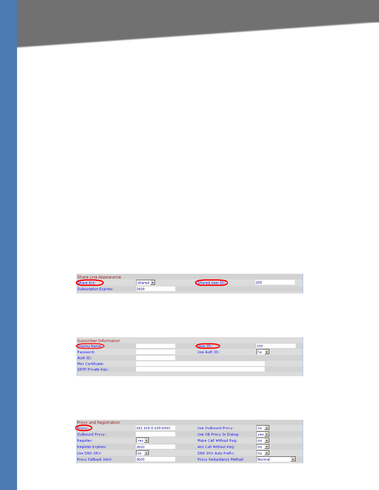
Linksys Voice System Administration Guide 78
Managing Inbound Calls with Shared Line Appearances
Configuring Phone Lines and Calling Routing Behavior
1. Connect to the SPA9000 administration web server, and choose Admin access with
Advanced settings. (See ”Connecting to the SPA9000 Administration Web Server,” on
page 24.)
2. Choose the client station that you want to configure:
a. Click the PBX Status link near the top right corner or lower left corner of the page to
view the list of client stations.
b. Click the hyperlink in the IP Address column for the first phone that you want to
configure. The telephone configuration page appears in a separate browser window.
3. Configure the shared extension on the selected station:
a. Click the tab for the extension that you want to configure (Ext 1 ... Ext n, depending on
the phone model).
NOTE: As a general practice, Linksys recommends that you always reserve Extension 1
on the client station as the primary and private extension of the designated user.
b. Scroll down to the Share Line Appearance section, and then enter the following settings:
–Share Ext: Choose shared.
–Shared User ID: Enter a user ID number for this SLA. After the line key is configured,
this ID will appear on the phone display and in the Corporate Directory.
SPA9xx Telephone Configuration > Ext: Shared Line Appearance
c. Scroll down to the Subscriber Information section, and then enter a User ID and Display
Name for this shared extension.
SPA9xx Telephone Configuration > Ext: Subscriber Information
d. Scroll down the Proxy and Registration section, and enter the same Proxy value as on the
primary extension for this station.
SPA9xx Telephone Configuration > Ext: Proxy and Registration
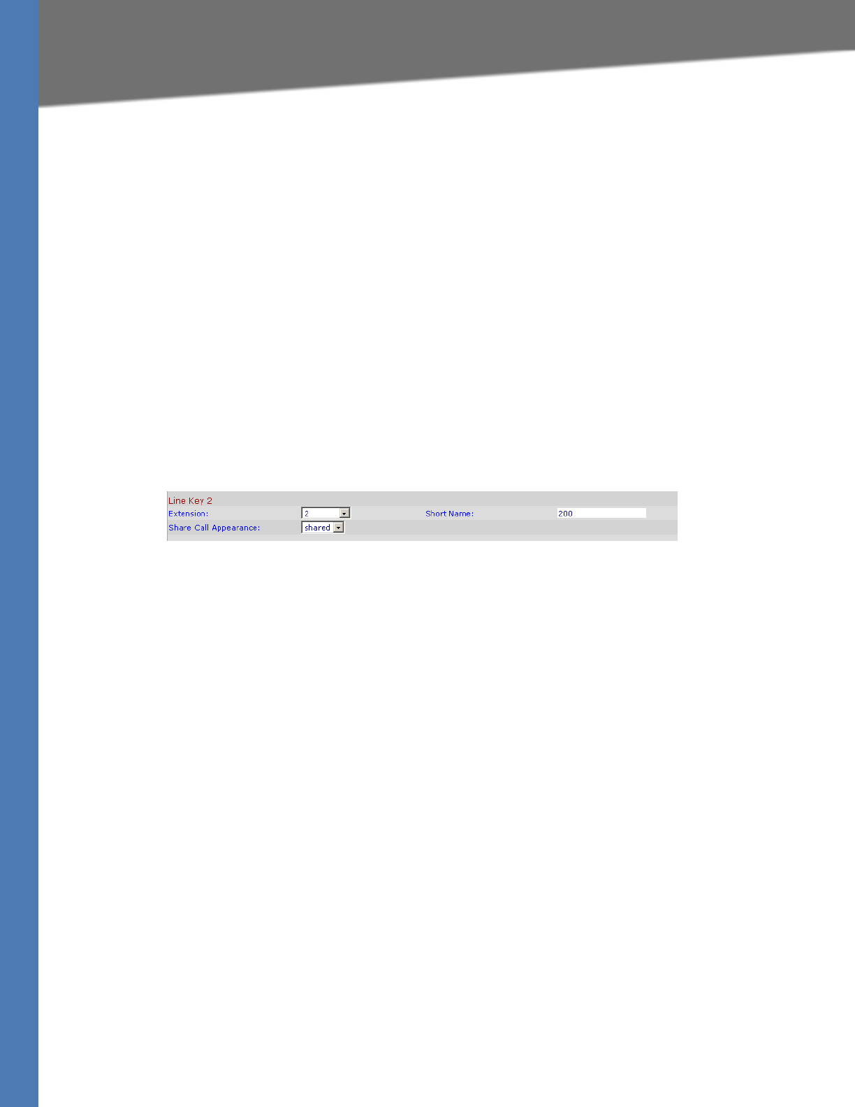
Linksys Voice System Administration Guide 79
Managing Inbound Calls with Shared Line Appearances
Configuring Phone Lines and Calling Routing Behavior
4. Configure a line key button for the shared extension:
a. Click the Phone tab.
b. Scroll down to the Line Key area for the line key button that you want to configure (Line 1
... Line n, depending on the phone model).
c. Enter the following settings to correspond with the entries that you made on the
Extension tab:
–Extension: From the drop-down list, choose the number corresponding to the Ext N
tab that you configured for this SLA. For example, if you configured the SLA on the
Ext 2 page, then choose 2 from the Extension drop-down list.
–Shared Call Appearance: From the drop-down list, choose shared.
–Short Name: Type the extension number that you entered as the Shared User ID for
the extension. This extension number will appear on the phone display and in the
Corporate Directory.
SPA9xx Telephone Configuration: Ext: Line Key
NOTE: You can configure additional line keys for the same SLA.
5. Click Submit All Changes.
6. Repeat this procedure for each phone that you want to configure with the SLA.

Linksys Voice System Administration Guide 80
5Connecting to the SPA400 Administration Web Server
Administering the SPA400 and Voice Mail Service
Administering the SPA400 and Voice
Mail Service
This chapter guides you through the process of configuring and managing the SPA400 for PSTN
access and voice mail service.
The SPA400 provides a SIP-PSTN gateway for voice connectivity between the PSTN and the
local client stations that are connected to the SPA9000. It also includes an integrated voice mail
application that supports up to 32 voice mail accounts with customized greetings, providing
LVS users the ability to receive and playback voice mail messages.
•”Connecting to the SPA400 Administration Web Server,” on page 80
•”Configuring the SPA400 Network Connection,” on page 81
•”Managing Access to the SPA400 Web-Based Configuration Utility,” on page 83
•”Upgrading the Firmware for the SPA400,” on page 84
•”Configuring a SPA400 to Interoperate with the SPA9000,” on page 85
•”Configuring a SPA400 for Voice Mail Service,” on page 87
•”Managing the Voice Mail Messages on the USB Key,” on page 94
•”Enabling Debugging on the SPA400,” on page 95
SEE ALSO: Appendix C, "SPA400 Field Reference"
Connecting to the SPA400 Administration Web Server
You can manage a SPA400 by using the web-based configuration utility.
Note If you have not already done so, connect the SPA400 to the same switch
as the SPA9000 and the SPA900 series IP phones. For more information,
see the SPA400 Quick Install Guide.
1. Start Internet Explorer, and enter the IP address of the SPA400 that you want to configure.
NOTE: Use Internet Explorer. By default, the SPA400 is configured to obtain an IP Address
via DHCP. You can check the obtained IP address on the router DHCP server’s client list.
2. When the password prompt appears, enter the default user name, Admin, with no
password. Then click OK.
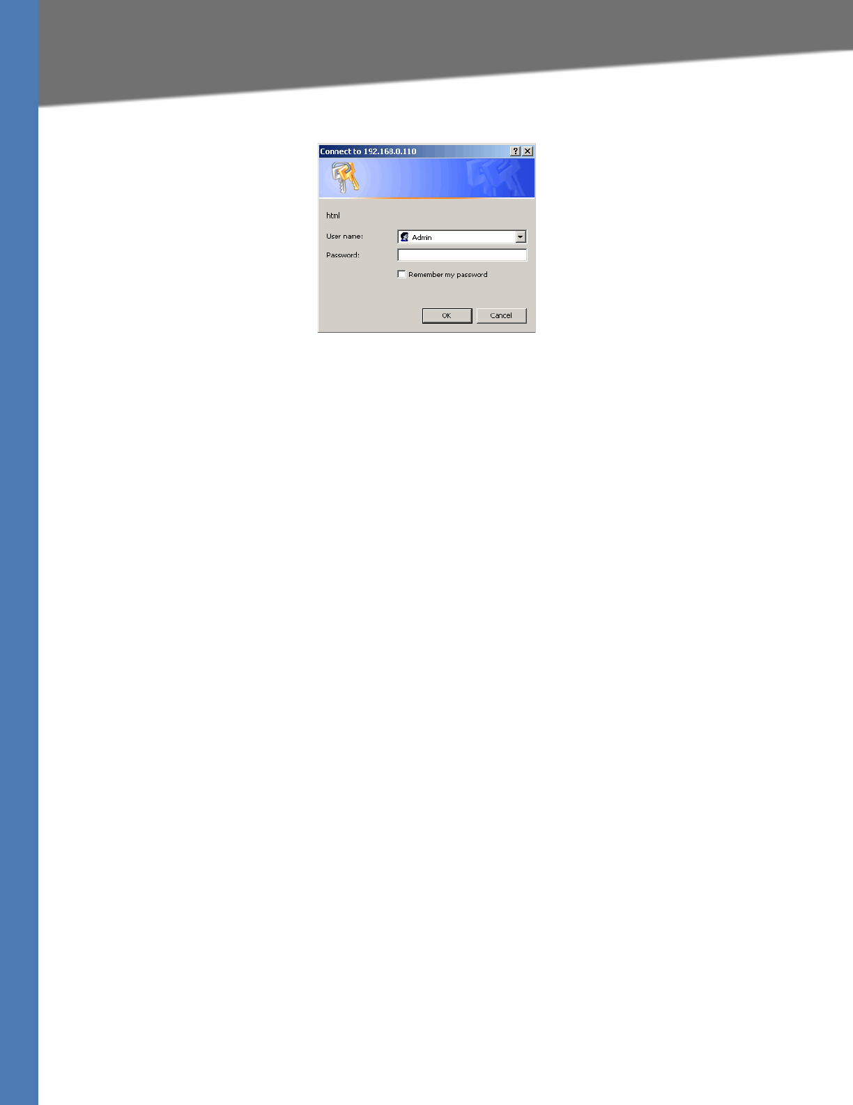
Linksys Voice System Administration Guide 81
Configuring the SPA400 Network Connection
Administering the SPA400 and Voice Mail Service
NOTE: The user name must be entered exactly as shown: Admin. By default, no password is
required, but a password can be set on the Administration > Management page. See
”Managing Access to the SPA400 Web-Based Configuration Utility,” on page 83.
Configuring the SPA400 Network Connection
The SPA400 becomes a DHCP client of any server on the network. The recommended setting is
to use a static IP address. This configuration provides ease of installation and prevents
connectivity issues that would occur if the IP address of the SPA400 changed.
1. Start Internet Explorer, and enter the IP address of the SPA400.
NOTE: By default, the SPA400 is configured to obtain an IP Address via DHCP. You can check
the obtained IP address on the router DHCP server’s client list.
2. When the password prompt appears, enter the default user name, Admin, with no
password. Then click OK.
NOTE: The user name must be entered exactly as shown: Admin. For information about
managing system access, refer to the LVS Administration Guide.
3. Click Setup tab > Basic Setup.
4. Enter the following settings:
Network Setup section:
•Fixed IP address: Click the radio button, and then enter a valid IP address.
NOTE: To avoid addressing conflicts, enter an IP address that is outside the range of
addresses that are automatically assigned by your DHCP server.
•IP Subnet Mask: Enter the subnet mask for the subnetwork that the SPA400 is on.
•Gateway IP Address: Enter the IP address of the router for this subnetwork.
Domain Name Server (DNS) Address section:
•Primary DNS: Enter the IP address of the primary DNS server.

Linksys Voice System Administration Guide 82
Saving or Discarding Changes on the SPA400
Administering the SPA400 and Voice Mail Service
•Secondary DNS: Enter the IP address of the secondary DNS server.
NTP section:
•NTP: Enter a fully qualified name of a Network Time Protocol server, such as
time.nist.gov.
•Time Zone: Select the time zone for your region.
5. Click Save Settings. The SPA400 will reboot. To reconnect to the web administration server,
enter the new IP address for the SPA400 in the browser Address bar.
Saving or Discarding Changes on the SPA400
Changes can be saved or discarded at any time.
• Changes are submitted only when you click the Save Settings button at the bottom of a
page.
• To discard unsubmitted changes, click the Cancel Changes button at the bottom of the
page.
• Unsubmitted changes are not retained when you move among the pages.
• After you submit changes in the SIP or Voice mail accounts settings, reboot the SPA400.
TIP: Before you make changes, save a copy of your
current working configuration:
1. In Internet Explorer, connect to the
administration web server.
2. Navigate to the page that has the settings that
you want to save.
3. From the menu, choose File > Save As.
4. Save the configuration as Web Page Complete.
The currently displayed page is saved. You can
use the saved file to review the settings as
needed.
5. Repeat these steps for each page, as needed.
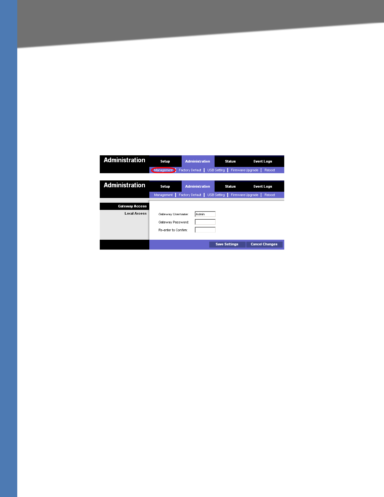
Linksys Voice System Administration Guide 83
Managing Access to the SPA400 Web-Based Configuration Utility
Administering the SPA400 and Voice Mail Service
Managing Access to the SPA400 Web-Based Configuration
Utility
One log on can be established for access to the SPA400 web-based configuration utility. The
default username of Admin can be changed, and a password can be entered.
1. Connect to the SPA400 administration web server. (See ”Connecting to the SPA400
Administration Web Server,” on page 80.)
2. Click Administration tab > Management.
SPA400 Administration > Management
3. Proceed as needed:
•Gateway Username: Type the desired username in this field, up to 32 characters.
•Gateway Password: Type the password.
•Retype to Confirm: Type the password again. Both entries must match exactly.
4. Click Save Settings.
5. To restart the SPA400, complete the following steps:
a. Click Administration tab > Reboot.
b. Click the Restart System button.
c. When the confirmation message appears, click OK. The SPA400 reboots.
d. When the Reboot OK. Go to Setup page? message appears, click OK and wait for 60
seconds (the time required for the SPA9000 to re-register with SPA400).
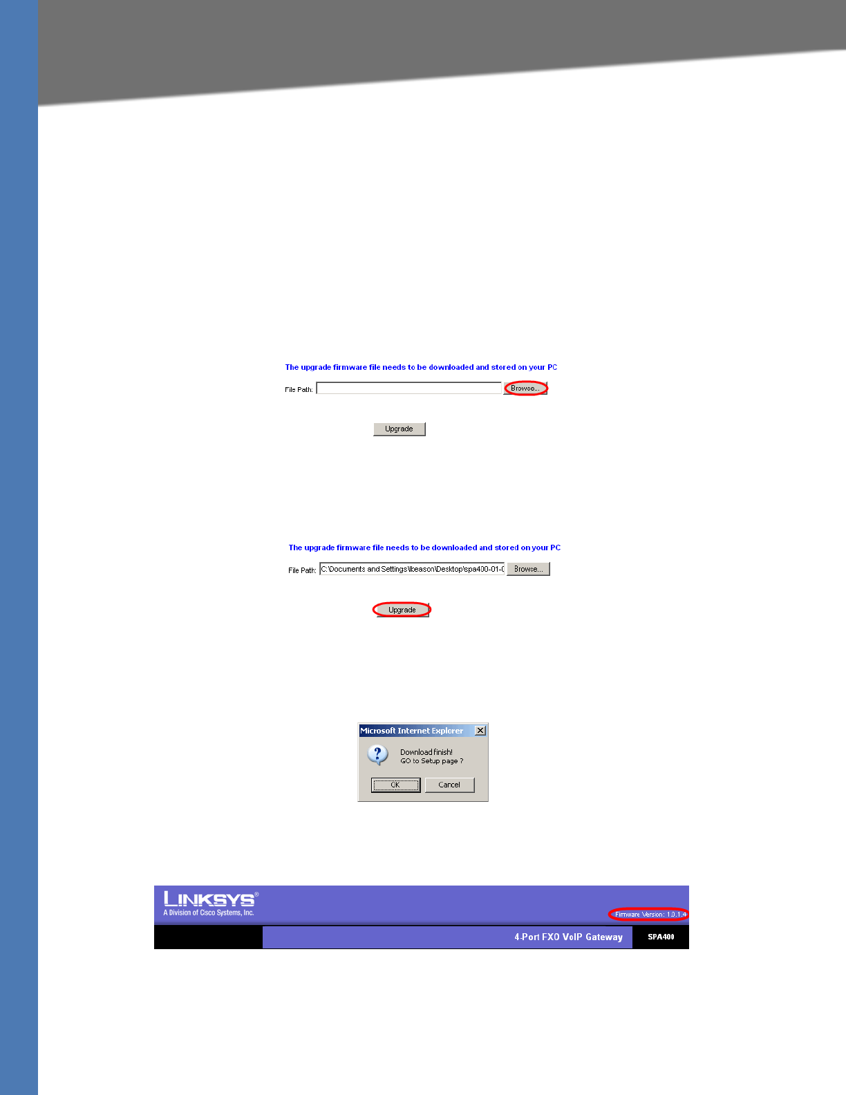
Linksys Voice System Administration Guide 84
Upgrading the Firmware for the SPA400
Administering the SPA400 and Voice Mail Service
Upgrading the Firmware for the SPA400
As needed, you can download new firmware from Linksys.com and then install the firmware on
the SPA400.
1. Connect to the SPA400 administration web server. (See ”Connecting to the SPA400
Administration Web Server,” on page 80.)
2. Click Administration tab > Firmware Upgrade.
3. Click Browse.
SPA400 Administration > Firmware Upgrade
4. Find the binary (.bin file) that you extracted to your Desktop, and click Open. The selected
file appears in the File Path field on the Firmware Upgrade page.
5. Click Upgrade.
6. When the confirmation message appears, click OK.
7. When the Setup page reappears, verify that the Firmware Version number matches the
firmware version that you installed. You have successfully upgraded the firmware.
SPA400 Main Page: Firmware Version
NOTE: You may need to refresh your browser to display the updated banner reflecting the
new version number.

Linksys Voice System Administration Guide 85
Configuring a SPA400 to Interoperate with the SPA9000
Administering the SPA400 and Voice Mail Service
Configuring a SPA400 to Interoperate with the SPA9000
A SPA400 must be configured to register the SPA9000. To enable the interoperation of the two
devices, you need to enter corresponding information on the SPA9000 Voice > Line page and on
the SPA400 Setup > SPA9000 Interface page. For voice mail service, additional entries are needed
on the SPA400 Setup > Voicemail Server page.
NOTES:
• Complete this procedure for each SPA400, whether it is used as a PSTN gateway or as a
voice mail server.
• You also must configure a SPA9000 line interface for this device. See ”Configuring a Line
Interface for a SPA400 (PSTN or Voice Mail),” on page 48.
• If you install multiple SPA400 units, keep track of the MAC addresses to ensure that you
know which device you are configuring. In the administration web server, you can see
the MAC address by clicking the Status tab.
1. Connect to the SPA400 administration web server. (See ”Connecting to the SPA400
Administration Web Server,” on page 80.)
2. When the password prompt appears, enter the user name and password. Then click OK.
NOTE: For more information about the administrator account, see ”Managing Access to the
SPA400 Web-Based Configuration Utility,” on page 83.
3. Click Setup tab > SPA9000 Interface.
4. Enter the following settings:
•User ID: 9000
This is the user ID that the SPA9000 will use to register with the SPA400. Any ID can be
used, but must match exactly the User ID that you entered on the corresponding
SPA9000 Voice > Line page.
•SPA9000 Address: Select the Discover Automatically radio button (required for
SPA9000 operation).
This setting enables the SPA400 to learn the IP address and the UDP port of the SPA9000
the from the SIP Registration packets sent by SPA9000.
•Call Signalling Packets: 68
•RTP Packets: b8
NOTES:
–Leave the Signalling Port at the default value of 5060. This port is the source port
that is used to originate signaling between the SPA400 and the SPA9000.
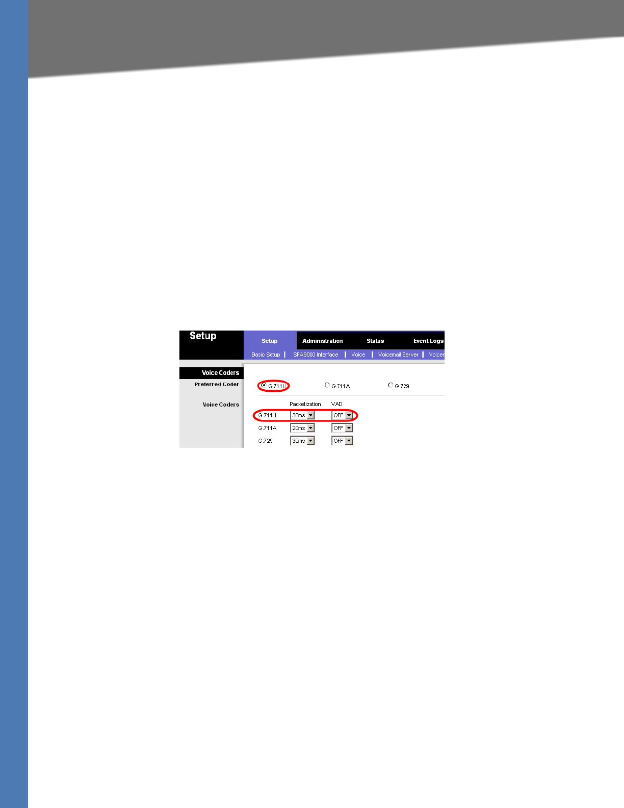
Linksys Voice System Administration Guide 86
Configuring a SPA400 to Interoperate with the SPA9000
Administering the SPA400 and Voice Mail Service
–Leave the RTP Port at the default value of 10000. This port is the base UDP port for the
block of UDP ports that the SPA400 uses to send and receive RTP and RTCP packets.
–Leave the Session Timer fields at the default values: Enabled with 0 seconds in both
Refresh Time fields.
5. Click Save Settings at the bottom of the page.
6. Click Setup tab > Voice.
7. Enter the following settings:
•Preferred Codec: Select G.711u.
•Packetization: Choose 30ms from the Packetization drop-down list for G.711U.
•VAD: Choose OFF from the VAD drop-down list for G.711U.
SPA400 Setup > Voice
8. Click Save Settings at the bottom of the page.
9. To restart the SPA400, complete the following steps:
a. Click Administration tab > Reboot.
b. Click the Restart System button.
c. When the confirmation message appears, click OK. The SPA400 reboots.
d. When the Reboot OK. Go to Setup page? message appears, click OK.
10. If you are using this SPA400 as a PSTN gateway, connect the RJ11 cables from the SPA400 to
the wall outlet for PSTN access.
11. To verify your progress, perform the following tasks:
•Click the Status tab, and confirm that the SIP registration status is Registered.
• If you connected PSTN lines to the ports on the SPA400, confirm that you can place an
external call to the phone number that is associated with the PSTN line. The call is
directed according to the Contact List. Also, in the SPA400 web configuration page, click
the Status tab, and then verify that a voltage value appears in the Battery Level section.
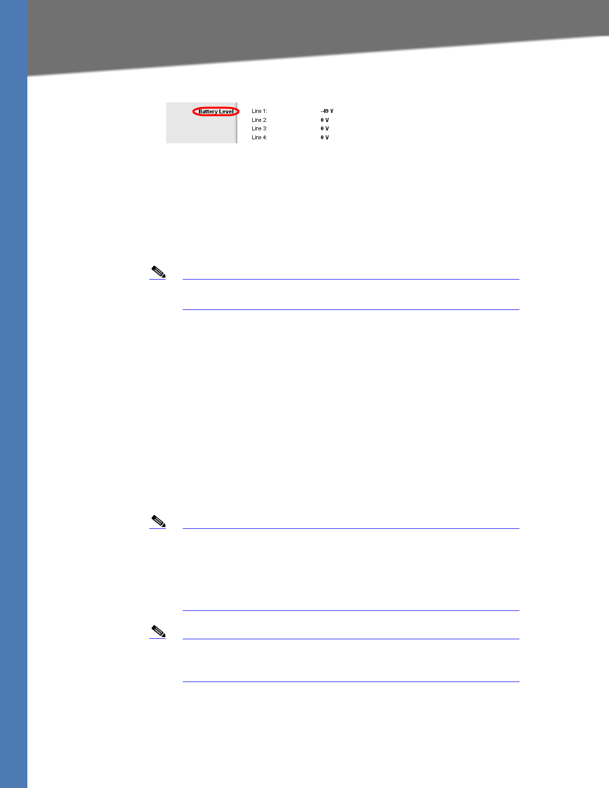
Linksys Voice System Administration Guide 87
Configuring a SPA400 for PSTN Access
Administering the SPA400 and Voice Mail Service
SPA400 Administration > Status: Battery Level
NOTE: If the battery level is 0 V on a line that you have connected to the PSTN,
troubleshoot the phone wiring.
• Connect to the SPA9000 administration web server, and choose Admin access with
Advanced settings. Click Voice tab > Info. Scroll down to the Line 2 Status section, and
verify that the Registration Status is Registered.
12. Click Save Settings.
Note If you are using this SPA400 for voice mail service, continue to
”Configuring a SPA400 for Voice Mail Service,” on page 87.
Configuring a SPA400 for PSTN Access
Typically, there is no need to change the default settings on the Voice page. Make changes only
if a problem is suspected and only after consulting with a service technician from your
telephone service provider. It is essential that the settings on your system are compatible with
those of the Central Office.
Configuring a SPA400 for Voice Mail Service
The SPA400 includes a USB adapter with an integrated voice mail application for the users and
extensions that are configured on the SPA9000. The integrated voice mail application server
supports 32 configurable voice mail accounts. Although a SPA9000 can be configured with up
to four SPA400 devices, only one SPA400 can be configured with the voice mail server.
Note Important: For optimum voice mail performance, a SPA400 should be
dedicated to the voice mail application when either of the following
conditions is met:
1) More than 2 FXO connections are required
—OR—
2) More than 2 users commonly access voice mail at the same time.
Note Before you begin any of the procedures in this section, configure a
SPA9000 line interface for this device. See ”Configuring a Line Interface
for a SPA400 (PSTN or Voice Mail),” on page 48.
This section includes the following topics:
•”Voice Mail Capacity,” on page 88

Linksys Voice System Administration Guide 88
Configuring a SPA400 for Voice Mail Service
Administering the SPA400 and Voice Mail Service
•”Configuring Local Voice Mail Service on a SPA400,” on page 88
•”Setting Up Voice Mail on Each Station,” on page 90
•”Enabling Remote Voice Mail Access (Optional),” on page 93
Voice Mail Capacity
The provided 128-Mb USB drive can store more than 3.8 hours of messages (approximately 230
60-second messages). For example, with 10 voice mail users, each user can store up to 23 60-
second messages. When disk capacity is reached, inbound voice mail deposit attempts are
disconnected. If additional voice mail storage is required, please contact Linksys for
recommended high-capacity USB drives.
Configuring Local Voice Mail Service on a SPA400
You need to configure the voice mail server and set up the voice mail boxes for the users.
NOTE: The settings on this page correspond to the settings on the SPA9000 Voice > Line page.
See ”Configuring a Line Interface for a SPA400 (PSTN or Voice Mail),” on page 48.
1. Connect to the SPA400 administration web server. (See ”Connecting to the SPA400
Administration Web Server,” on page 80.)
2. Click Setup tab > Voicemail Server.
3. Enter the following information:
•Server Port: 5090
The voice mail server uses this UDP port to listen for signalling between the SPA400 and
the SPA9000. This port must be different from the port number that you entered on the
SPA9000 Interface page.
•SPA9000 subscriber ID: 8888
The SPA9000 uses the subscriber ID to subscribe to the SPA400 Voice mail Server for
obtaining notification.
•Mailbox deposit number: 900
The SPA9000 uses the deposit number to deposit voice mail on the voice mail server.
•Mailbox manage number: 800
The SPA9000 uses the deposit number to access voice mail on the voice mail server.
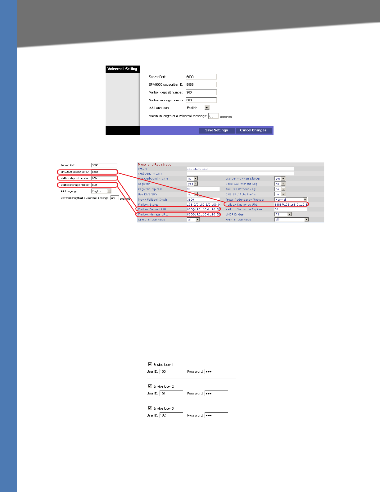
Linksys Voice System Administration Guide 89
Configuring a SPA400 for Voice Mail Service
Administering the SPA400 and Voice Mail Service
SPA400 Setup > Voicemail Server: Voicemail Setting
NOTE: These settings correspond to the settings on the SPA9000 Voice > Line page.
4. Click Save Settings.
5. Configure the voice mail users (required):
a. Click the Voicemail Users tab.
b. Enable the voice mail accounts and enter the user’s extensions and passwords:
–Enable: Select the check box to enable the voice mail account.
–User ID: Enter the user’s extension number.
–Password: Enter a password for this user. Users can change their own passwords
after logging on with the assigned password.
SPA400 Setup > Voicemail Users
NOTE: Later you configure each client station for voice mail access to the mail boxes
that you create on this page.
6. Click Save Settings at the bottom of the page.
SPA400 > Setup > Voicemail Server SPA9000 > Voice > Line N
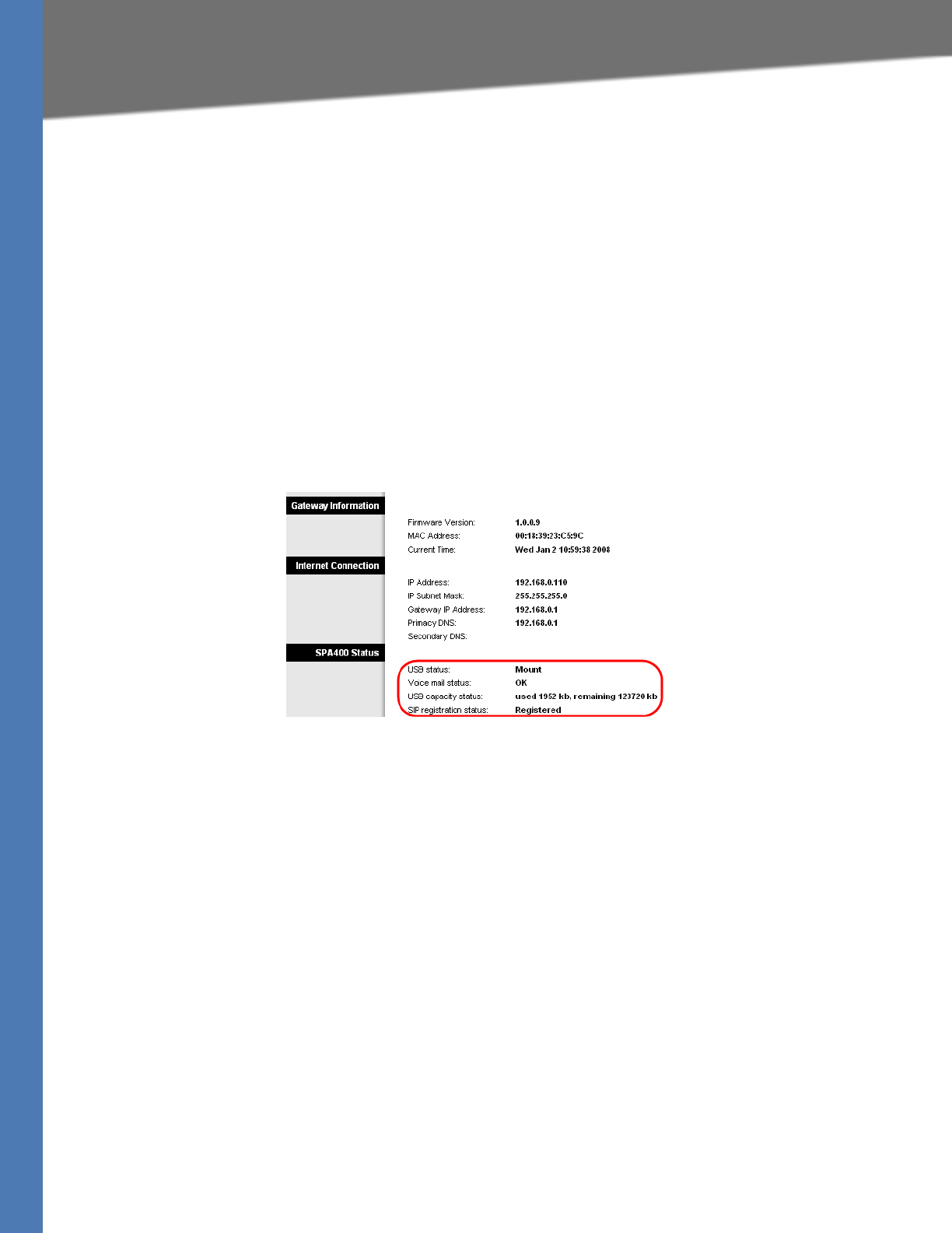
Linksys Voice System Administration Guide 90
Configuring a SPA400 for Voice Mail Service
Administering the SPA400 and Voice Mail Service
7. Restart the SPA400 by completing the following steps:
a. Click Administration tab > Reboot.
b. Click the Restart System button.
c. When the confirmation message appears, click OK. The SPA400 reboots.
d. When the Reboot OK. Go to Setup page? message appears, click OK.
8. To verify your progress, click the Status tab, and verify the following settings:
•USB status: Mount
•Voice mail status: OK
•SPA9000 Registration status: Registered
SPA400 Status
NOTE: If the SPA registration status is not Registered, trying powering off the SPA9000 and
powering it on again.
9. Continue to the next procedure, ”Setting Up Voice Mail on Each Station,” on page 90.
Setting Up Voice Mail on Each Station
You need to set up each station that needs to have a voice mailbox. Perform this procedure
after you have configured both the SPA400 and the SPA9000.
1. Connect to the SPA9000 administration web server. (See ”Connecting to the SPA9000
Administration Web Server,” on page 24.)
2. Click the PBX Status link near the top right corner or lower left corner of the page. The
screen lists each phone by Station Name and Extension number.
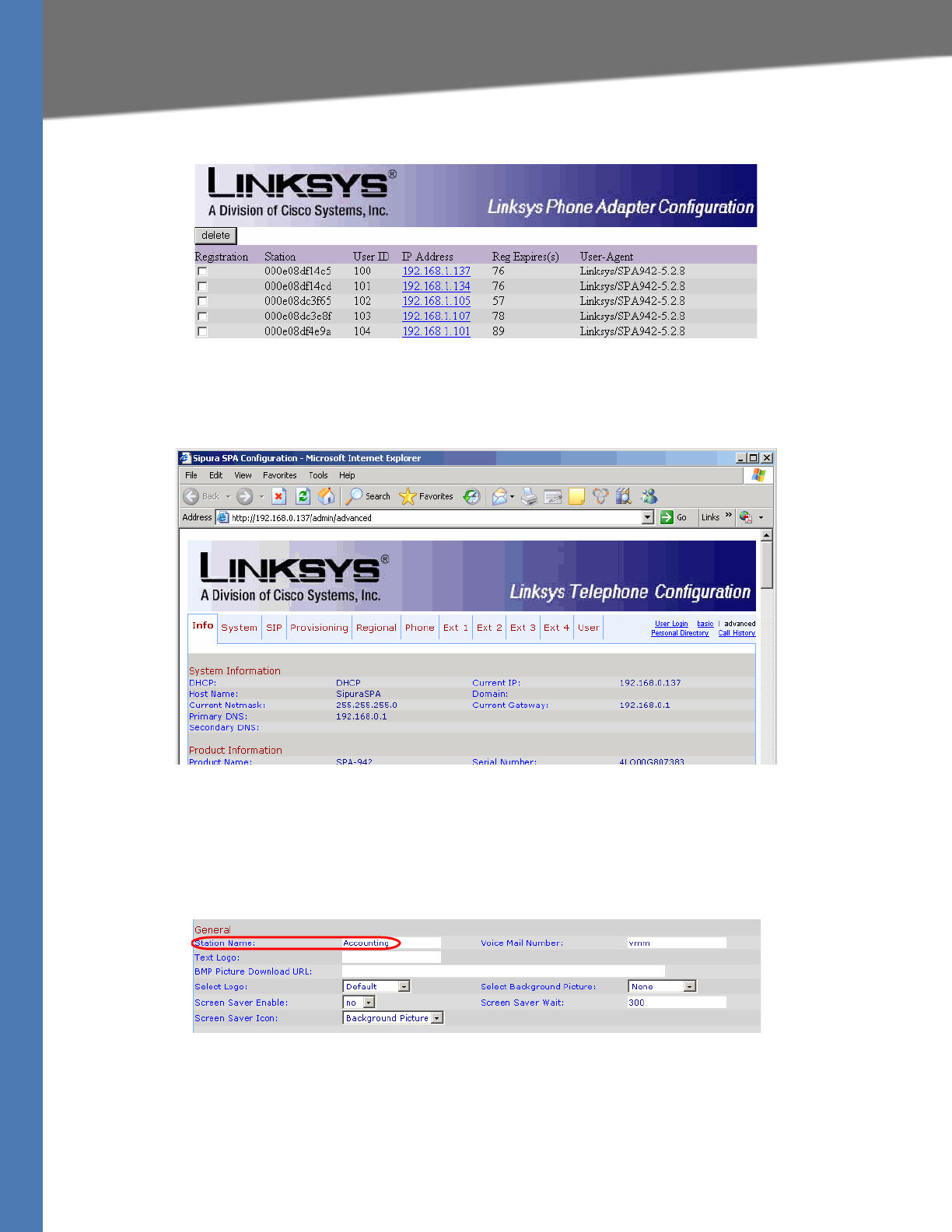
Linksys Voice System Administration Guide 91
Configuring a SPA400 for Voice Mail Service
Administering the SPA400 and Voice Mail Service
SPA9000 PBX Status
3. Find the phone that you want to configure, and then click the hyperlink in the IP Address
column. The Telephone Configuration page appears in a separate browser window.
SPA9xx Telephone Configuration > Info
4. To assign a station name, complete the following steps:
a. Click the Phone tab.
b. In the General section, type a name in the Station Name field.
SPA9xx Telephone Configuration > Phone: General
NOTE: This setting assists you in managing the phones. The station name appears on
the phone display, in the Corporate Directory, and in features such as Group Call Pickup,
that list the participating phones in a menu.
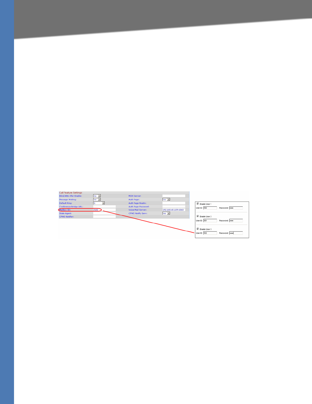
Linksys Voice System Administration Guide 92
Configuring a SPA400 for Voice Mail Service
Administering the SPA400 and Voice Mail Service
5. To assign a voice mail box to the primary extension, complete the following steps:
a. Click the Ext 1 tab.
b. Scroll down to Call Feature Settings.
c. Enter the Mailbox ID in the following format:
<lineN><mailbox>
Example: 2105
– lineN: The SPA9000 line (1, 2, 3, or 4) that is configured with the voice mail settings
In the example, 2 is the number of the SPA9000 line interface that is configured for
the SPA400 voice mail server.
– mailbox: The voice mailbox number for this station, as configured on the SPA400
Voice Mail Users page.
In the example, voice mailbox 105 is assigned to the station.
NOTE: The mailbox value corresponds to a User ID on the SPA400 voice mail server.
6. Click Submit All Changes. The phone reboots.
7. Close the browser window for this station.
8. Return to the browser window that shows the list of stations, and then repeat this
procedure for each station that you need to configure.
NOTE: When you finish configuring stations, you can click the Back button on the browser
toolbar to return to the main web configuration page.
9. To verify your progress, perform the following tasks:
•Station Name: Verify that the station name appears on the phone display and in the list
of stations on the PBX Status page.
•Mailbox Status: Connect to the SPA9000 administration web server, and choose Admin
access with Advanced settings. Click Voice tab > Line 2. In the Proxy and Registration
section, check the Mailbox Status field. You should see a listing for each extension that
you configured with voice mail. Refer to the following example.
Phone Configuration > Ext N
SPA400 > Setup > Voicemail Users
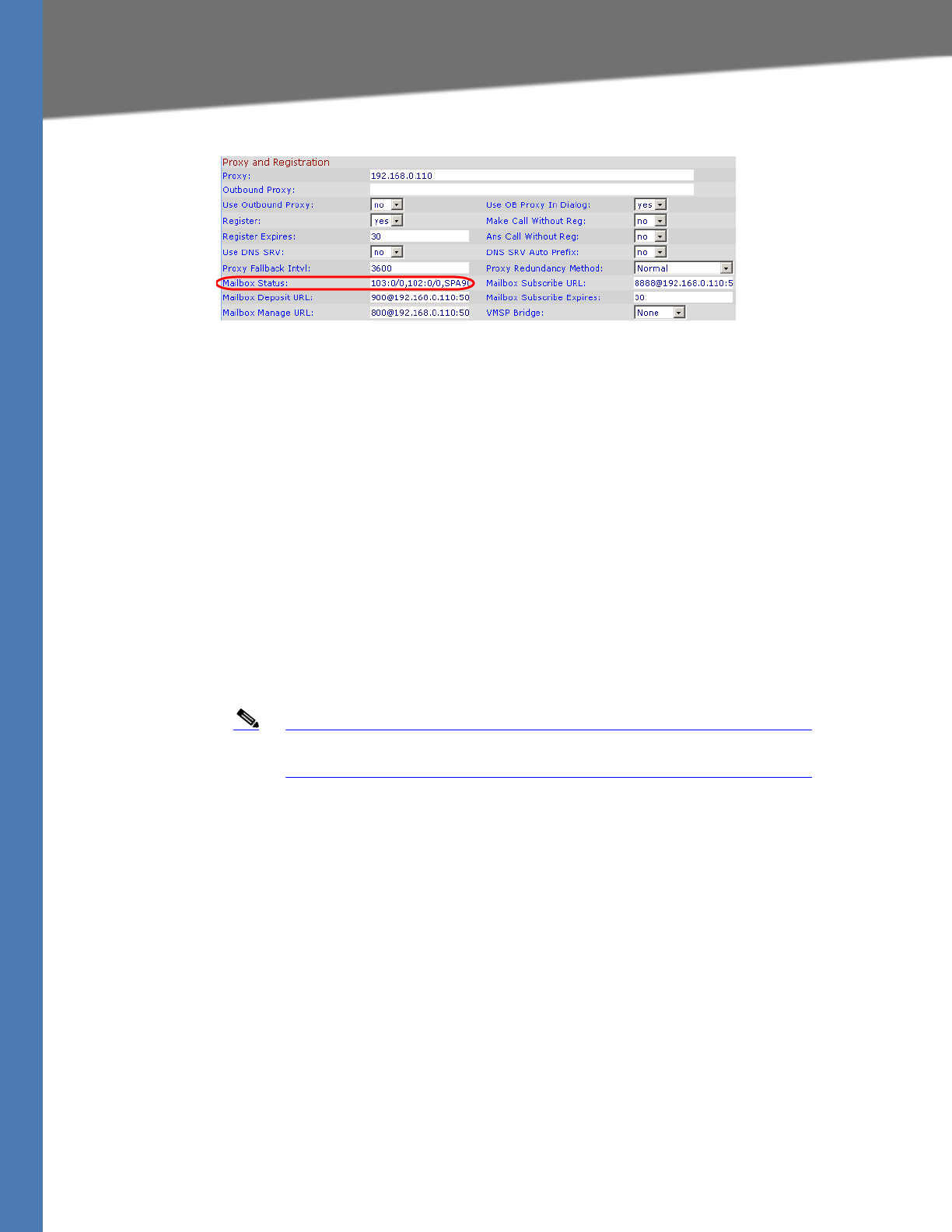
Linksys Voice System Administration Guide 93
Configuring a SPA400 for Voice Mail Service
Administering the SPA400 and Voice Mail Service
SPA9000 Voice > Line: Proxy and Registration
•Voice Mail: Press the Message button. You hear one of the following responses:
– “Password”: If you are prompted for a password, the station is configured properly.
You can enter the password and manage the mailbox.
– “Mailbox number”: If you are prompted for the mailbox number, a mailbox is not
assigned to this station. Review the settings on the SPA400 Voice mail User page (see
“Configuring the Voice Mail Server and Voice Mail Users on the SPA400” on page_53)
and the Phone configuration page (see “Setting Up Each Station” on page_55).
– Busy Tone: A busy tone indicates a problem with the configuration. Verify that the
USB drive is properly inserted into the SPA400, and review the various entries that
you made in the configuration.
Enabling Remote Voice Mail Access (Optional)
You can configure the SPA9000 to allow the users to check their voice mail when they are out of
the office.
Note If your users will call into your voice mail system through an ITSP line,
your ITSP must support out-of-band DTMF (IE RFC2833).
1. Connect to the SPA9000 administration web server. (See ”Connecting to the SPA9000
Administration Web Server,” on page 24.)
2. Click Voice tab > SIP.
3. Scroll down to the Auto Attendant Parameters section.
4. Edit the AA Dial Plan 1 string to include a code for the voice mail server, as described below.
•SYNTAX: (10x|xxx.|<dialcode:vmmN>)
•EXAMPLE: (10x|xxx.|<8:vmm2>)
• dialcode: The digit that users dial, when prompted by the Auto Attendant, to access
voice mail remotely.
NOTE: The Contact List for this line must be configured for the Auto Attendant to
answer.
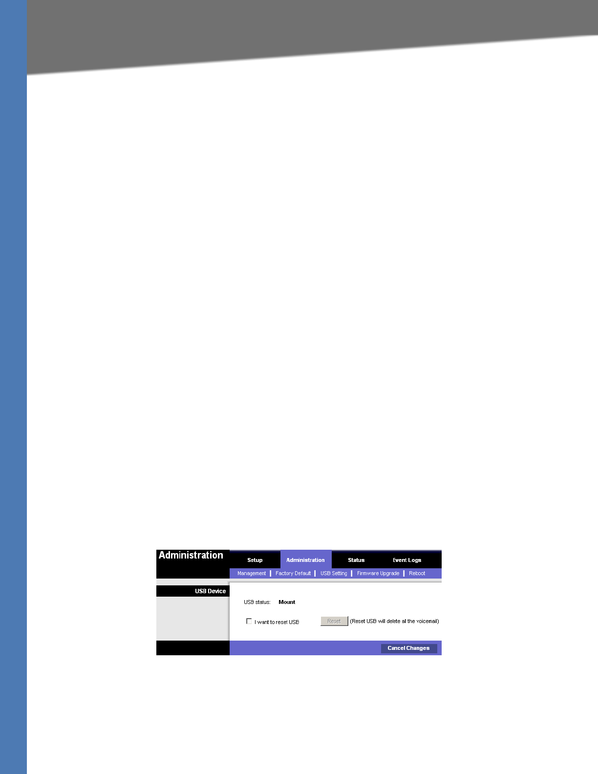
Linksys Voice System Administration Guide 94
Managing the Voice Mail Messages on the USB Key
Administering the SPA400 and Voice Mail Service
• MailboxManageNumber: The Mailbox Manage Number that was entered on the SPA400
Voice mail Settings page. If you followed the instructions in the procedure “Configuring
the SPA400” on page_48, you set 800 as the Mailbox Manage Number.
•vmmN: Replace N with the number of the SPA9000 line interface (Line 1 ... Line 4) that is
configured for the SPA400 voice mail server.
5. Copy and paste the same string into the AA Dial Plan 2 field, for the purpose of allowing
remote access of voice mail at all times of day. For more information about AA Dial Plans,
refer to ”Configuring Dial Plans for the Auto Attendant,” on page 117.
6. Click Voice tab > Line N, where N is the number of the line interface for this SPA400 unit.
7. Make sure that the VMSP Bridge, XFER Bridge Mode, and CFWD Bridge Mode fields are set to
all.
8. Click Submit All Changes. The SPA9000 and the phones reboot.
9. To verify your progress, perform the following tasks:
a. Dial into the site from an external number.
b. When the Auto Attendant prompts you for an extension, press 8.
c. When the Voice Mail Server prompts for a mailbox number, enter the mailbox number.
d. When prompted for a password, enter the password.
Managing the Voice Mail Messages on the USB Key
To delete unneeded voice mail messages on the USB key, refer to the procedure below.
1. Connect to the SPA400 administration web server. (See ”Connecting to the SPA400
Administration Web Server,” on page 80.)
2. Click Administration tab > USB Setting.
3. Check the I want to reset USB check box.
4. Click Reset.
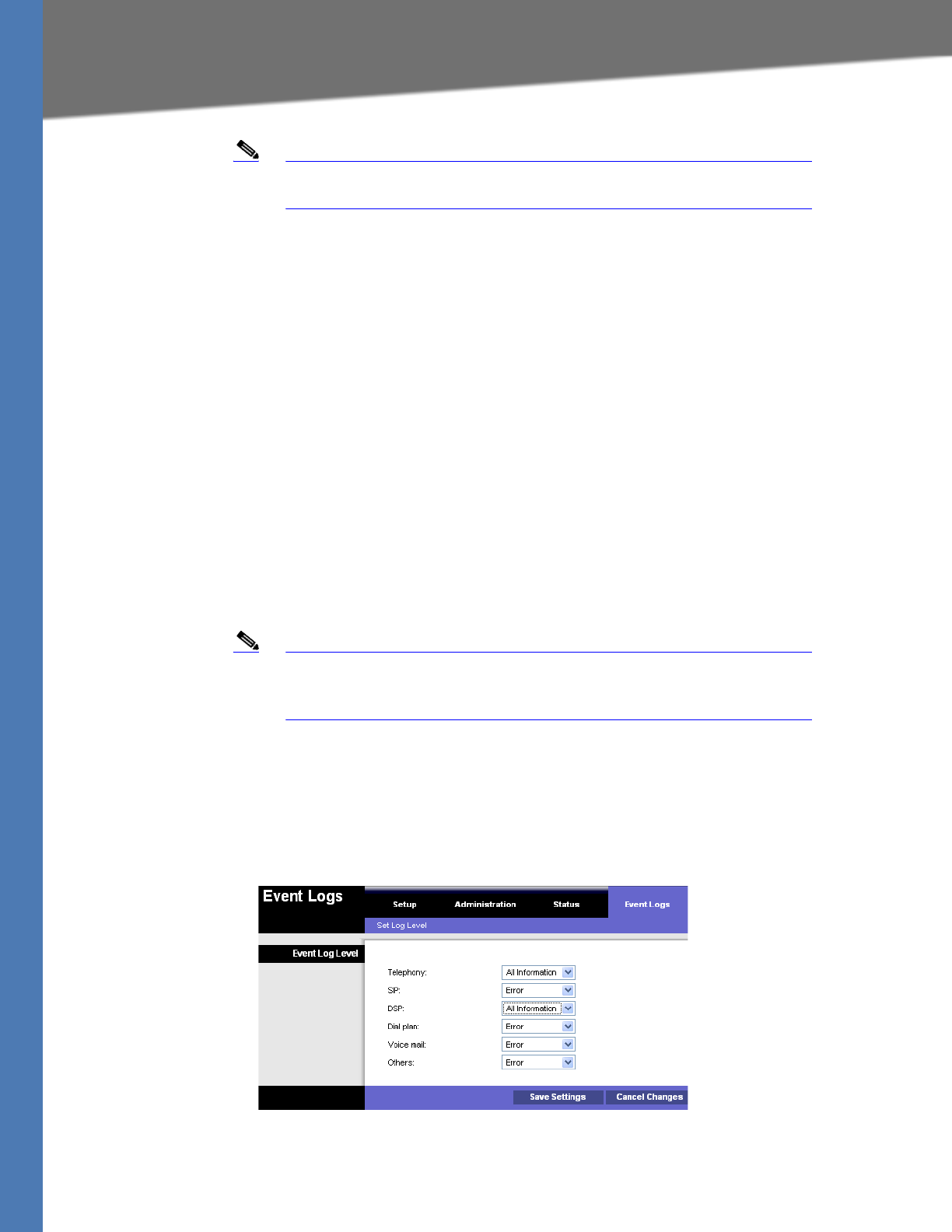
Linksys Voice System Administration Guide 95
Enabling Debugging on the SPA400
Administering the SPA400 and Voice Mail Service
Note All the voicemail of all users will be deleted. The deleted voicemail
messages are not recoverable.
5. When the confirmation message appears, click OK to continue or click Cancel to end the
operation without deleting the messages.
Enabling Debugging on the SPA400
If you are investigating issues, you can collect system logs and debug information for the
SPA400.
Requirements:
• You need a PC that is on the same subnetwork as the SPA9000, to capture the log files.
This PC needs to be running a syslog daemon. Enter the IP address of this PC on the
Voice > System page, in the Syslog Server and Debug Server fields.
• If you are interested in working with these logs yourself, you will need to use an
application that reads syslogs. Linksys partners can download a syslog server tool
(slogsrv.exe) from the Linksys Partner Connection. (VARs, see Product Utilities > Linksys
Voice System > SPA Utilities > Syslog Server for SPA Devices. SPs, see Technical Tools >
SPA Utilities > Syslog Server for SPA Devices.)
Note As a best practice, enable logging only when needed, and disable
logging when you finish the investigation. Logging information can
impact system performance.
1. Connect to the SPA400 administration web server. (See ”Connecting to the SPA400
Administration Web Server,” on page 80.)
2. Click Event Logs tab.
3. Use the drop-down lists to choose the types of information that you want to collect.
4. Click Save Settings.
5. Click Setup tab > Basic Setup.
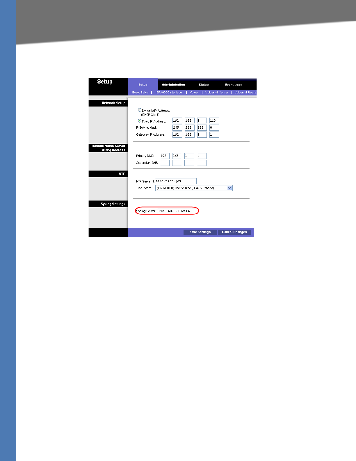
Linksys Voice System Administration Guide 96
Enabling Debugging on the SPA400
Administering the SPA400 and Voice Mail Service
6. In the Syslog Settings section, enter the IP address of the Syslog Server, which normally is a
PC on the same network as the SPA400.
7. Start a command prompt on the PC, and run the system logging software.
8. Run the scenario that causes the problem and when done, press CTRL+C in the command
window to stop the logs.
9. When you are finished collecting logs, return to the Event Logs page and reset the logs to
Off.

Linksys Voice System Administration Guide 97
6Using the Internal Music Source for Music On Hold
Configuring Music on Hold
Configuring Music on Hold
This chapter explains how to configure Music on Hold using either a music file or streaming
audio.
This chapter includes the following topics:
•”Using the Internal Music Source for Music On Hold,” on page 97
•”Configuring a Streaming Audio Server,” on page 99
Using the Internal Music Source for Music On Hold
The SPA9000 has an internal music source with the user ID imusic that plays an internally
stored music file repeatedly. The SPA9000 ships with a default music file (Romance de Amor).
You can override this file by downloading a new file into the unit by using TFTP.
Refer to the following topics:
•”Using the Internal Music Source,” on page 97
•”Changing the Music File for the Internal Music Source,” on page 98
•”Restoring the Original Music File,” on page 98
Using the Internal Music Source
The SPA9000 has an internal music source that plays an internally stored music file repeatedly.
The SPA9000 ships with a default music file (Romance de Amor).
1. Use the phone menu to find the IP address of the phone:
a. Press the Setup button on the phone keypad.
b. Press 9 - Network, and then scroll down to 2- Current IP Address.
2. Start Internet Explorer, and then enter the IP address of the telephone. The Telephone
Configuration page appears in a separate browser window.
3. Click Admin Login, and then click Advanced.
4. Click the Ext 1 tab.
5. Scroll down to the Call Feature Settings section.
6. Enter the following value in the MOH Server field: imusic
7. Click Submit All Changes.
8. To verify, place a test call to the extension. When the call is answered and put on hold, the
caller should hear the default music file (Romance de Amor).

Linksys Voice System Administration Guide 98
Using the Internal Music Source for Music On Hold
Configuring Music on Hold
Changing the Music File for the Internal Music Source
The following resources are required to change the music file for the internal music source:
•TFTP server software
• The IP address of the administration computer that is connected to the SPA9000
• A music source in G.711u format, sampled at 8000 samples/sec with no file header, up to
65.5 seconds in length, with no header information
1. Before you begin, make sure that you have TFTP server software running on your computer.
2. Connect to the SPA9000 administration web server, and choose Admin access with
Advanced settings. (See ”Connecting to the SPA9000 Administration Web Server,” on
page 24).
3. Click Voice tab > SIP.
4. Scroll down to the Internal Music Source Parameters section.
5. Enter the following URL in the Internal Music URL field:
tftp://server_IPaddress:portpath
• server_IPaddress: The local IP address of the computer you are using as the TFTP server
• port: The port number used by the TFTP server (default 69)
• path: The location and name of a music file in the correct format
• For example, if the computer local IP address is 192.168.0.5, the directory is named
musicdir, and the converted music file is named jazzmusic.dat, then you would enter the
following URL: tftp://192.168.0.5:69/musicdir/jazzmusic.dat
6. Click Submit All Changes. The SPA9000 reboots. Then the SPA9000 downloads the file and
stores it in flash memory.
Restoring the Original Music File
If you want to restore the original default music file for the internal music source, you can
download the file from Linksys.com.
1. On Linksys.com, choose Support > Technical Support.
2. Click Choose A Product.
3. Choose IP PBX from the Voice over IP drop-down list.
4. Under Downloads, choose the Click Here link.
5. Choose the correct version in the drop-down list.
6. Under Others, click the Default Music File link.

Linksys Voice System Administration Guide 99
Configuring a Streaming Audio Server
Configuring Music on Hold
7. Unzip this file and save it to an accessible directory on your TFTP server. Then repeat this
procedure and enter the correct server IP address, port, and the path to the unzipped file.
Configuring a Streaming Audio Server
This section describes how to use and configure a streaming audio server (SAS). It includes the
following topics:
•”Using a Streaming Audio Server,” on page 99
•”Using the IVR with an SAS Line,” on page 100
•”Example SAS with MOH,” on page 100
•”Configuring the Streaming Audio Server,” on page 101
Using a Streaming Audio Server
On a connected call, the SPA9000 may place the remote party on hold by performing a hook-
flash to initiate a three-way call or by swapping two calls during call-waiting. If the remote
client indicates that it can still receive audio while the call is holding, the SPA9000 can be
configured to contact an auto-answering streaming audio server (SAS) to stream audio to the
holding party. When used this way, the SAS is referred to as an MOH Server.
The SAS feature lets you use attach an audio source to one of the SPA9000 FXS ports (Phone 1
or Phone 2 on the PAP2T) and use it as a streaming audio source device. If the SPA9000 has
multiple FXS ports, either or both of the associated lines (Line 1 and Line 2 on the PAP2T) can
be configured as an SAS server.
When the line is called and the FXS port is off hook, the SPA9000 answers the call automatically
and streams audio to the calling party.
If the FXS port is on-hook when the incoming call arrives, the SPA9000 replies with a SIP 503
response code to indicate “Service Not Available.” If an incoming call is auto-answered, but later
the FXS port changes to on-hook, the SPA does not terminate the call but continues to stream
silence packets to the caller. If an incoming call arrives when the SAS line has reached full
capacity, the SPA replies with a SIP 486 response code to indicate “Busy Here.”
The SAS line can be setup to refresh each streaming audio session periodically using a SIP re-
INVITE message, which detects if the connection to the caller is down. If the caller does not
respond to the refresh message, the SAS line terminates the call so that the streaming resource
can be used for other callers.
Each SAS server can maintain up to five simultaneous calls. If the second line on the SPA9000 is
disabled, then the SAS line can maintain up to 10 simultaneous calls. Further incoming calls
receive a busy signal (SIP 486 Response).
The streaming audio source must be off-hook for the streaming to occur. Otherwise incoming
calls get a error response (SIP 503 Response). The SAS line does not ring for incoming calls even
if the attached equipment is on-hook.
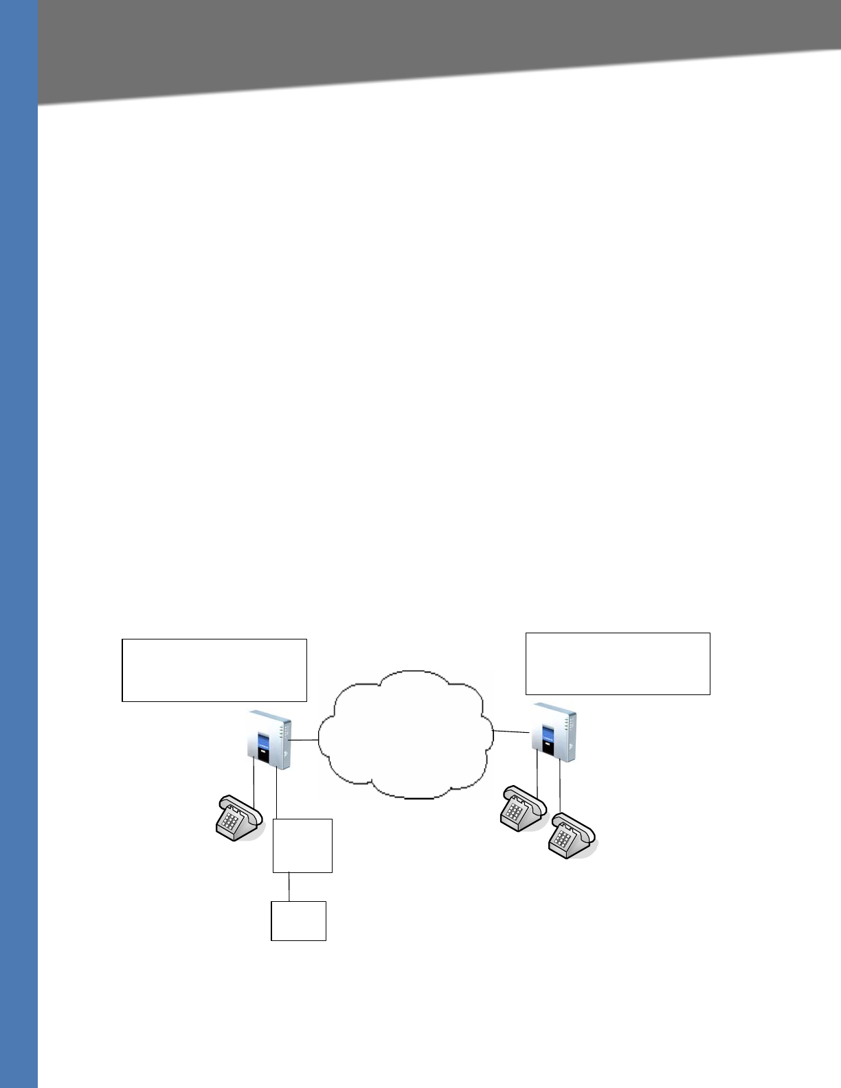
Linksys Voice System Administration Guide 100
Configuring a Streaming Audio Server
Configuring Music on Hold
If no calls are in session, battery is removed from tip-and-ring of the FXS port. Some audio
source devices have an LED to indicate the battery status. This can be used as a visual indication
as to whether audio streaming is in progress.
Set up the Proxy and Subscriber Information for the SAS Line as you normally would with a
regular user account.
Call Forwarding, Call Screening, Call Blocking, DND, and Caller-ID Delivery features are not
available on an SAS line.
Using the IVR with an SAS Line
The IVR can still be used on an SAS line, but the user needs to follow the following steps:
1. Power off the SPA9000.
2. Connect a phone to the port and make sure the phone is on-hook.
3. Power on the SPA9000.
4. Pick up handset and press * * * * to invoke IVR in the usual way.
If the SPA9000 boots and finds that the SAS line is on-hook, it does not remove battery from the
line so that IVR may be used. But if the SPA9000 boots up and finds that the SAS line is off-hook,
it removes battery from the line because no audio session is in progress.
Example SAS with MOH
Figure 6-1 MOH Application with a SPA9000 Line Configured as an SAS
In this example, the SAS Line is registered with the SPA9000 as the other subscribers.
IP Network
Phone 1 Phone 2
Phone 1 Phone 2
Media
signal
adapter
SPA1:
IP=192.168.2.100
UserID[1]=1001, SIP Port[1]=5060
UserID[1]=1002, SIP Port[1]=5061
SPA2:
IP=192.168.2.200
UserID[1]=2001, SIP Port[1]=5060
UserID[1]=2002, SIP Port[1]=5061
Line in
Music
source

Linksys Voice System Administration Guide 101
Configuring a Streaming Audio Server
Configuring Music on Hold
On SPA1:
SAS Enable[1] = no
MOH Server [1] = 1002
SAS Enable[2] = yes
On SPA2:
SAS Enable[1] = no
MOH Server [1] = 1002
SAS Enable[2] = no
MOH Server [2] = 1002
Configuring the Streaming Audio Server
The following provides step-by-step procedures for implementing a SAS with an external music
source.
1. Connect an RJ-11 adapter between the music source (a CD player or iPod, for example) and
an FXS port on the SPA9000 (Phone 1 or Phone 2).
2. Connect to the SPA9000 administration web server, and choose Admin access with
Advanced settings. (See ”Connecting to the SPA9000 Administration Web Server,” on
page 24).
3. Configure the FXS port:
a. Click Voice tab > FXS N, where N represents the SPA9000 phone port number where
you connected the RJ-11 adapter.
b. Enter the following settings:
–Display Name: Enter an extension number of name for the FXS 1 port, such as
Receptionist Area Fax Machine.
–User ID: Enter a three- to four-digit extension number that is not is use by other
extension.
c. Scroll down to the Streaming Audio Server (SAS) section.
d. From the SAS Enable drop-down list, choose yes.
Voice > FXS N > Streaming Audio Server
4. Click Submit All Changes.

Linksys Voice System Administration Guide 102
Configuring a Streaming Audio Server
Configuring Music on Hold
5. Configure each phone to use this audio source as the MOH server:
a. Click the PBX Status link to view the list of phones.
b. In the list, find the phone that you want to configure, and then click the hyperlink in the
IP Address column. The Telephone Configuration page appears in a separate window.
c. Click the Ext 1 tab.
d. Scroll down to the Call Feature Settings section.
e. In the MOH Server field, enter the extension number that you assigned to the FXS port
for the streaming audio server.
f. Click Submit All Changes.
g. Close the window for the Telephone Configuration page.
h. Repeat this step to configure each phone, as needed.

Linksys Voice System Administration Guide 103
7How the Auto Attendant Works
Configuring the LVS Auto-Attendant
Configuring the LVS Auto-Attendant
This chapter describes how to configure the LVS Auto Attendant using the IVR, and XML
scripting.
This chapter contains the following sections:
•”How the Auto Attendant Works,” on page 103
•”Working with the Auto Attendant Greetings,” on page 104
•”Writing an Auto Attendant Script,” on page 108
•”Configuring the DayTime, NightTime and Weekend/Holiday Auto Attendants,” on
page 116
•”Configuring Dial Plans for the Auto Attendant,” on page 117
How the Auto Attendant Works
The Auto Attendant (aa) is an internal service within the SPA9000. This service answers calls and
plays pre-recorded voice messages that offer a menu of choices. The Auto Attendant parses the
user input (key presses or DTMF tones), based on the Auto Attendant Dial Plan. Finally, the Auto
Attendant routes the call to the selected extension.
The Auto Attendant can handle up to ten incoming calls simultaneously. It can accommodate
two categories of callers:
• Callers who do not call you regularly or are not accustomed to using Auto-Attendants.
The Auto Attendant plays a greeting and provides menus to help callers reach the
desired extension.
• Callers who call you regularly and want to move through the system quickly. The Auto
Attendant allows experienced users to input their responses at any time.
The Auto Attendant relies upon the following components:
•Contact List. When a call comes in, the SPA9000 directs the call according to the entries
in the Contact List for the line interface. By default, the Auto Attendant is the only client
on this list, so the Auto Attendant picks up every call. Alternatively, you can enter a list of
client stations to alert, with the Auto Attendant picking up a call only if a number (or
group) of clients did not pick up the call first. This parameter is configured on the Voice >
Line N page, Subscriber Information section, Contact List field. For more information, see
”Managing Inbound Calls with the Contact List,” on page 66.
•Recorded Prompts. The Auto Attendant plays prompts to assist the users. The system
includes a set of pre-recorded prompts, and you can record your own custom prompts.
For more information, see ”Working with the Auto Attendant Greetings,” on page 104.
•AA Script. This XML script determines which prompt is used to greet callers and which
prompts are played in response to valid or invalid user inputs. You can enter up to three
scripts. One script is active at any time. These scripts are configured on the Voice > SIP

Linksys Voice System Administration Guide 104
Working with the Auto Attendant Greetings
Configuring the LVS Auto-Attendant
page, Auto Attendant Parameters section, AA Script 1 - 3 fields. For more information, see
”Writing an Auto Attendant Script,” on page 108.
•DayTime, NightTime, and Weekend/Holiday AA. You can activate different AA scripts
for different times of day. By default, the DayTime AA settings are activated and use AA
Script 1. As needed, you can activate the NightTime AA and the Weekend/Holiday AA,
with your selection of a script (AA Script 1, 2, or 3). You also need to define the start and
end time for daytime, nighttime, and weekend/holiday. For more information, see
”Configuring the DayTime, NightTime and Weekend/Holiday Auto Attendants,” on
page 116.
•AA Dial Plan. The Auto Attendant parses the user input according to the dial plan that
is identified in the AA script. You can create up to two dial plans. These dial plans are
configured on the Voice > SIP page, Auto Attendant Parameters section, AA Dial Plan 1 - 2
fields. See ”Configuring Dial Plans for the Auto Attendant,” on page 117.
Working with the Auto Attendant Greetings
This section provided information about adding, and editing the Auto Attendant greetings. See
the following topics:
•”Using Pre-Recorded Prompts,” on page 104
•”Recording an Auto Attendant Prompt,” on page 105
•”Downloading Prompts,” on page 107
Using Pre-Recorded Prompts
You can save up to ten Auto Attendant prompts. Four pre-recorded prompts are provided, as
listed in Table 7-1.
Note These prompts are available in languages other than English. See
”Localizing the SPA9000 Auto Attendant Prompts,” on page 118.
You can replace the pre-recorded prompts with your own recordings, and you can add up to six
additional recordings. For example, you may want to change the default prompt, Prompt 1, to
greet callers with your company name. You may want to record a different prompt for
nighttime or holiday hours. You can make these recordings by using the IVR. The recordings are
encoded with G.711U and saved in flash.
Table 7-1 Prompts
Prompts ID Default Audio Content
Prompt1 “If you know your party’s extension, you may enter it now.”
Prompt2 “Your call has been forwarded.”
Prompt3 “Not a valid extension, please try again.”
Prompt4 “Goodbye.”

Linksys Voice System Administration Guide 105
Working with the Auto Attendant Greetings
Configuring the LVS Auto-Attendant
Recording an Auto Attendant Prompt
Follow this procedure to overwrite an existing recording or to add a new recording.
Note Customized prompts are erased when a factory reset is performed on
the SPA9000.
1. Connect an analog phone to the Phone 1 or Phone 2 port of the SPA9000.
2. Press the star key (*) four times: ****
The IVR plays the following prompt: Linksys configuration menu. Please enter the option
followed by the # (pound) key or hang up to exit.
3. Press 72255# to access the Auto Attendant message settings.
The IVR plays the following prompt: Please enter the message number followed by the #
(pound) key.
4. Enter the number of the message (1 through 10) that you wish to record, review, or delete.
The IVR plays the following prompt: Enter 1 to record. Enter 2 to review. Enter 3 to delete. Enter
* to exit.
5. Press 1 to record a new message.
NOTE: The IVR checks the available buffer size. If there is no more buffer capability, IVR plays
the Option Failed message and returns to the previous menu.
If the buffer space is sufficient, the IVR plays the following prompt: You may record your
message after the tone. When finished, press #.
6. After the tone, record the new message and then press #.
The IVR plays the following prompt: To save, enter 1. To review, enter 2. To re-record, enter 3. To
exit, enter *.
7. Press 1 to save the new recorded message.
The IVR plays the following prompt: One moment, please.
8. Wait for several seconds while the save is completed.
Linksys Voice System Administration Guide 106
Working with the Auto Attendant Greetings
Configuring the LVS Auto-Attendant
Example Prompts
In this example, the business will have different Auto Attendant Scripts for different times of
day.
For examples of AA scripts that use custom prompts, see ”An Introduction to XML Scripting
Grammar in AA Script Examples,” on page 109.
Prompt ID Message
Prompt1 “If you know your party’s extension, you may enter it now.”
Prompt2 “Your call has been forwarded.”
Prompt3 “Not a valid extension, please try again.”
Prompt4 “Goodbye.”
Prompt5 “Welcome to All Seasons Travel.”
Prompt6 “Thank you for calling All Seasons Travel. Presently we are closed.”
Prompt7 “We are open Monday through Friday 9 AM to 6 PM, and we are
closed on Saturdays and Sundays. Our address is 101 Main Street,
Anytown, Anystate, USA.”
Prompt8 “If you know your party’s three-digit extension, you may enter it
now.”
Prompt9 “To reach our receptionist, press 0 at any time. For our company
location, press 1. For travel support, press 2. For sales, press 3.
Otherwise, please stay on the line for our receptionist.”
Prompt10 “Welcome to the All Seasons Travel support line. If this is regarding
our Holiday Getaway Special, please press 1; otherwise, please stay
on the line for one of our travel associates. Or press * to go back.”
Linksys Voice System Administration Guide 107
Working with the Auto Attendant Greetings
Configuring the LVS Auto-Attendant
Using the IVR Prompts to Change Recordings
The IVR prompts guides you through the process of recording, erasing, and changing greetings.
Refer to Figure 7-1.
Figure 7-1 IVR Prompt Menu Call Flow
Downloading Prompts
You can download customized prompt files from a TFTP/HTTP/HTTPS server. These files must
be encoded in G.711u, size less than 60 seconds, with the header removed. The total prompt
file size cannot be larger than 94.5 seconds.
The prompt is downloaded at the device boot up time. If the prompt has already been
downloaded from the given URL, the download is not performed. If the prompt file name is
none, the corresponding prompt currently saved in the flash is erased. The default value is
blank.
Menu-1
Play prompt (“Please enter message
number followed by the # key”)
User enters
prompt key
(
1-10
)
Menu-2
Play prompt (“Enter 1 to record,
enter 2 to review, enter 3 to
delete
,
enter * to exit”
)
Retrieve the
prompt data and
play prompt
User enters 2 User enters 1
User enters *
Menu-3-A
Play prompt (“You may record your
message after the tone. When
finished
,
p
ress #.”
)
Goto menu-1
User records
a
p
rom
p
t
Menu-4-A
Play prompt (“to save enter 1, to
review enter 2, to rerecord enter
3, to exit enter *.”)
Play prompt
(“Value saved”)
User enters 1
Play user
recorded
prompt
User enters 2 User enters 3 User enters *
User enters
72255 from IVR
Goto menu-3-A
Goto menu-2
Goto
menu
4-A
Goto menu-2
User enters 3
Menu-3-B
Play prompt (“enter 1 to
confirm, enter * to exit
User enters 1
Erase messa
g
e
User enters *
Play prompt
(“Message erased.”)

Linksys Voice System Administration Guide 108
Writing an Auto Attendant Script
Configuring the LVS Auto-Attendant
1. Connect to the SPA9000 administration web server, and choose Admin access with
Advanced settings. (See ”Connecting to the SPA9000 Administration Web Server,” on
page 24).
2. Click Voice tab > SIP.
3. Scroll down to the Auto Attendant Parameters section.
4. In the AA Prompts URL Script field, enter the location and the file name for the prompts files,
in the following format:
SYNTAX:
serv=scheme://server_addr[:port]/root_path;[p1={prompt1 file path name};][p2={prompt2 file
path name};][p3={prompt3 file path name};][p4={prompt4 file path name};][p5={prompt5 file
path name};][p6={prompt6 file path name};][p7={prompt7 file path name};][p8={prompt8 file
path name};][p9={prompt9 file path name};][p10={prompt10 file path name};]
• scheme = tftp|http|https
• default port is 69 for tftp, 80 for http, and 443 for https
• root_path can be empty
• [ ] denotes optional item
• none: The prompt will be erased.
EXAMPLE:
serv=tftp://192.168.2.150/root/test/;p1=menu.wav;p2=transfer.wav;p3=nomatch.wav;p4=none;
In this example, Prompt 1 is downloaded from tftp://192.168.2.150/root/test/menu.wav,
Prompt 2 from tftp://192.168.2.150/root/test/transfer.wav, and Prompt 3 from tftp://
192.168.2.150/root/test/nomatch.wav. Prompt 4 is erased.
5. Click Submit All Changes.
Writing an Auto Attendant Script
The SPA9000 AA allows users to define the AA instructions using XML script. This section
includes the following topics:
•”An Introduction to XML Scripting Grammar in AA Script Examples,” on page 109
•”Elements of XML Scripting Grammar ,” on page 111
•”Auto Attendant XML Instructions Set,” on page 113
•”Entering an Auto Attendant Script,” on page 115

Linksys Voice System Administration Guide 109
Writing an Auto Attendant Script
Configuring the LVS Auto-Attendant
An Introduction to XML Scripting Grammar in AA Script Examples
The SPA9000 lets you use XML scripting grammar to define the Auto Attendant instructions.
You can study the example scripts to learn about the scripting grammar. You also may find it
helpful to use these scripts as the basis for your own custom scripts.
SEE ALSO: ”Elements of XML Scripting Grammar ,” on page 111
Example 1: Routing Calls to Any Extension Number (Default AA Script 1)
In this example, the business is using the default AA Script 1, which prompts the caller to enter
any extension number. Each part of the script is described in the following table.
Script Elements Purpose
<aa> This script is for the AA.
<form id=”dir” type=”menu”> This form is given the name “dir” for directory,
and it is a menu type of form, which accepts
DTMF inputs.
<audio src=”prompt1” bargein=”T”/> The Auto Attendant plays Prompt 1, using the
default recording: If you know your party’s
extension, you may enter it now.
Callers are allowed to begin dialing (bargein) at
any time.
<noinput timeout=”10” repeat=”T”/> If there is no input after 10 seconds, the Auto
Attendant repeats the menu prompt.
<dialplan src=”dp1”/> AA Dial Plan 1 is used to evaluate the inputs.
<nomatch repeat=”F”>
<audio src=”prompt3” bargein=”T”/>
</nomatch>
If the dialed digits do not match the dial plan, the
Auto Attendant plays Prompt3: Not a valid
extension, please try again.
<match>
<default>
<audio src=”prompt2”/>
<xfer name=”ext” target=”$input”/>
</default>
</match>
If the dialed digits match the dial plan, the Auto
Attendant plays Prompt 2 (Your call has been
forwarded.) The call is transferred to the
extension number that the user entered.
</form> The form is ended.
</aa> The script is ended.
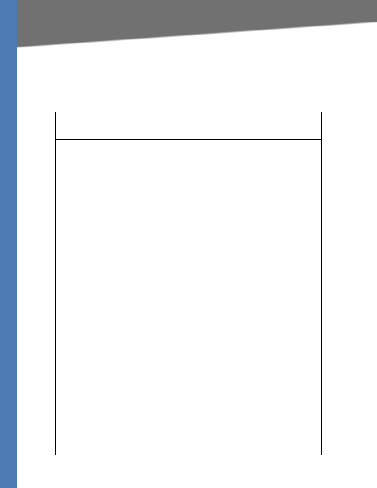
Linksys Voice System Administration Guide 110
Writing an Auto Attendant Script
Configuring the LVS Auto-Attendant
Example 2: Routing Calls with a Departmental Sub-Menu
In this example, the business wants to expedite the handling of sales calls. A custom prompt is
used to give special instructions about calls for the sales department. A sub-menu for the sales
group is provided to direct calls to the correct person within that department.
Script Elements Purpose
<aa> This script is for the AA.
<form id=”DIR” type=”menu”> This form is given the name “DIR” for Directory.
It is a menu type of form, which accepts DTMF
inputs.
<audio src=”prompt1” bargein=”T”/> The Auto Attendant plays custom Prompt1.
Welcome to ABC company. For Sales, enter 1.
If you know your party’s extension, you may
enter it now.
Callers are allowed to begin dialing (bargein) at
any time.
<dialplan src=”dp1”/> Dial plan 1 is used to evaluate the inputs within
this form.
<noinput timeout=”10” repeat=”T”/> If there is no input after 10 seconds, the Auto
Attendant repeats the menu prompt.
<nomatch>
<audio src=”prompt3” bargein=”T”/>
</nomatch>
If the user input does not match the specified
dial plan, the Auto Attendant plays Prompt3:
Not a valid extension, please try again.
<match>
<case input=”1”>
<goto next=”SALES”/>
</case>
<default>
<audio src=”prompt2”/>
<xfer name=”ext” target=”$input”/>
</default>
</match>
If the user input matches the dial plan, the
response depends upon the user entry:
• If the user pressed 1, the Auto
Attendant processes the input by using
the Sales sub-menu (below in this
script).
• If the user pressed any keys other than
1, the Auto Attendant plays Prompt 2 (Your
call has been transferred.) The call is
transferred to the extension number that
the user entered.
</form> The “DIR” form is closed.
<form id=”SALES” type=”menu”> This part of the script contains the “SALES” sub-
form.
<audio src=”prompt5”/> The Auto Attendant plays custom Prompt 5:
Press 1 for price info, press 2 for return, press 0
for sales representative, press * to exit.
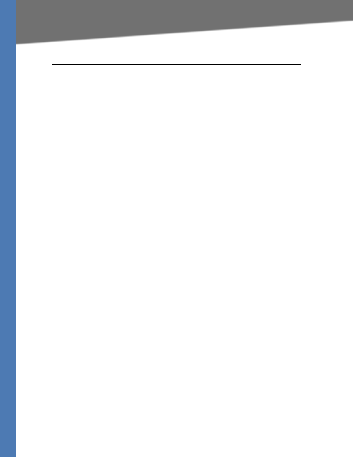
Linksys Voice System Administration Guide 111
Writing an Auto Attendant Script
Configuring the LVS Auto-Attendant
Elements of XML Scripting Grammar
This section includes the following topics:
•”Audio Instruction,” on page 111
•”Action Instruction,” on page 112
•”Noinput Instruction ,” on page 112
•”Nomatch Instruction,” on page 113
•”Menu Matched Instruction for Touch Tone (DMTP) Input,” on page 113
Audio Instruction
The following is an example of the audio instruction:
<audio src= “prompt1” bargein= “T”/>
The Auto Attendant plays the audio file that is specified in the src attribute. When playing the
audio, the Auto Attendant allows the caller to interrupt the current prompt by pressing digits
when the bargein attribute is set to T. The Auto Attendant ignores any digits from the caller if
bargein is set to F. The default value of the bargein attribute is T.
<dialplan src=”dp2”/> AA Dial Plan 2 is used to evaluate the inputs.
within this form.
<noinput timeout=”10” repeat=”T”/> If there is no input after 10 seconds, the Auto
Attendant repeats the menu prompt.
<nomatch>
<audio src=”prompt3” bargein=”T”/>
</nomatch>
If the user input does not match the specified
dial plan, the Auto Attendant plays Prompt3:
Not a valid extension, please try again.
<match>
<case input=”*”>
<audio src=”prompt4”/>
<exit/>
</case>
<default>
<audio src=”prompt2”/>
<xfer name=”ext” target=”$input”/>
</default>
</match>
If the user input matches the dial plan, the
response depends upon the user entry:
• If the user presses *, the Auto Attendant
plays Prompt 4: Good-bye.
• If the user presses any digits other than
*, the Auto Attendant plays Prompt 2 (Your
call has been transferred.) The call is
transferred to the extension number that
the user entered.
</form> The form is ended.
</aa>” The script is ended.
Script Elements Purpose

Linksys Voice System Administration Guide 112
Writing an Auto Attendant Script
Configuring the LVS Auto-Attendant
Action Instruction
The actions include:
•goto—The Auto Attendant proceeds to the next dialog in the script. All dialogs are
identified by the attribute “id”. The value in the id attribute must be unique. Otherwise,
the Auto Attendant selects the last valid dialog as the transfer target dialog.
EXAMPLE: <goto link= “dir_dlg”>
•xfer—The Auto Attendant blind transfers the caller to the target.
EXAMPLE: <xfer name= “Technical Support” target= “5000”/>
The name attribute is optional. The target attribute must be a valid target phone
number.
•exit —When this action is reached, the Auto Attendant is stopped, and the call ends.
EXAMPLE: </exit>
NOTE: In one dialog, only one action can be defin0ed. After the xfer or exit action is
performed, the Auto Attendant ends automatically.
Noinput Instruction
The <noinput> dialog can only be used in the menu dialog and is optional. When it is specified,
Auto Attendant executes the audio and action instructions if the user does not input any digits
with the value of the <timeout> parameter, in seconds.
If the repeat attribute is set to T, the Auto Attendant plays the menu prompt after playing the
prompt specified in the <noinput> dialog and ignores the action instruction. If the value is F,
the Auto Attendant executes the action instruction. The default value of the repeat attribute is
F.
Either the audio or the action instruction can be empty. If both are empty, the Auto Attendant
does nothing and waits for user input.
TIP: Generally, enter an audio instruction as the first
element in the script. In a <form> dialog, if <audio>
dialog is not been defined, the Auto Attendant does
not play a prompt. If it is defined, the Auto Attendant
first plays the specified prompt, then executes the
action instruction that is described in the next
section.

Linksys Voice System Administration Guide 113
Writing an Auto Attendant Script
Configuring the LVS Auto-Attendant
Nomatch Instruction
The <nomatch> dialog can be used only in a menu dialog and is optional. This dialog is
activated when DMTF digits do not match the dial plan. When the nomatch condition is met,
Auto Attendant executes the audio and action instructions in the <nomatch> dialog. If the
repeat attribute is set to T, the Auto Attendant plays the menu prompt after playing the no
input prompt and ignores the action instruction. If the repeat attribute is set to F, the Auto
Attendant executes the action instruction. The default value of the repeat attribute is F.
Either the audio or action instruction can be empty. If both are empty, the Auto Attendant
does nothing and ignores all buffered digits.
Menu Matched Instruction for Touch Tone (DMTP) Input
The <match> dialog can be used only in the menu dialog and it is a mandatory field. When the
DTMF digits match the dialplan, the <match> dialog is activated. The Auto Attendant compares
each <case> dialog and executes the corresponding audio/action instructions. If the Auto
Attendant cannot find a match in any <case> dialogs, it performs the <default> dialog audio/
action instruction if <default> is defined; otherwise, the Auto Attendant ends.
You can specify exact numbers, (for example 1, 23, 1234 and so on), in the input attribute of the
<case> dialog, or you can use the dial pattern (for example, “50xx”, “408xxx5061”, “xx.”). The user
can also combine several dial patterns together and use “|” to separate them (for example,
“50xx|408xxx5061|1234”).
The user can use the variable “$input” in the target attribute of the xfer action. The value of this
variable means that the input value that is already passed by the dialplan. The Auto Attendant
does no translation, but directly transfers the call to the target.
EXAMPLE
<default>
<audio src=”prompt2”/>
<xfer name=”ext” target=”$input”/>
</default>
Outband DTMF (INFO/AVT) is recognized by Auto Attendant. To enable the recognition of
inband DTMF, go to the Voice > SIP page, Auto Attendant Parameters section, and set AA Decode
Inband DTMF to yes.
Auto Attendant XML Instructions Set
The complete set of XML instructions for Auto Attendant Scripts are described in the following
table:

Linksys Voice System Administration Guide 114
Writing an Auto Attendant Script
Configuring the LVS Auto-Attendant
Instruction Description Syntax and Example(s)
dialplan This determines the dialplan id of the current
menu <form>. The Auto Attendant
processes the user input according to the
dial plan and then is dispatched to the
match, nomatch, or noinput instruction.
<dialplan src = “dp1”/>
“dp1” matches the AA Dial Plan 1
parameter found on the Voice - SIP screen
of the administration web server.
“dp2” matches the AA Dial Plan 2
parameter found on the Voice - SIP screen
of the administration web server.
noinput When specified, the Auto Attendant
executes the specified audio and action
instructions if the user does not input any
digits in <timeout> seconds. If the repeat
attribute is set to “T”, then the Auto
Attendant plays the menu prompt after
playing the prompt specified in the
<noinput> audio instruction and ignore the
action instruction; otherwise, the Auto
Attendant executes the action instruction.
By default, “repeat” is “F”.
<noinput timeout=”5” repeat=”T”>
<!--audio instruction (optional) -->
<!--action instruction (optional) -->
</noinput>
nomatch When specified, the nomatch instruction
runs when the user input digits do not
match anything in the dial plan. The Auto
Attendant executes the specified audio and
action instructions. If the repeat attribute is
set to “T”, the Auto Attendant plays the menu
prompt after playing the no input prompt
and ignore the action instruction; otherwise,
the Auto Attendant executes the action
instruction. By default, “repeat” is “F”.
<nomatch repeat=”F”>
<!--audio instruction (optional) -->
<!--action instruction (optional) -->
</nomatch>
match Upon a match between the user input and
the dial plan, the Auto Attendant transfers to
the corresponding <case> and execute the
corresponding audio and/or action
instructions. If the Auto Attendant cannot
find a match in any of the <case>
statements, it performs the <default> case.
<match >
<case input= “x”/>
<!--audio instruction (optional) -->
<!--action instruction (optional) -->
</case>
<case input= “#”/>
<!—audio instruction (optional) -->
<!--action instruction (optional) -->
</case>
<default>
<!—audio instruction (optional) -->
<!--action instruction (optional) -->
</default>
</match>
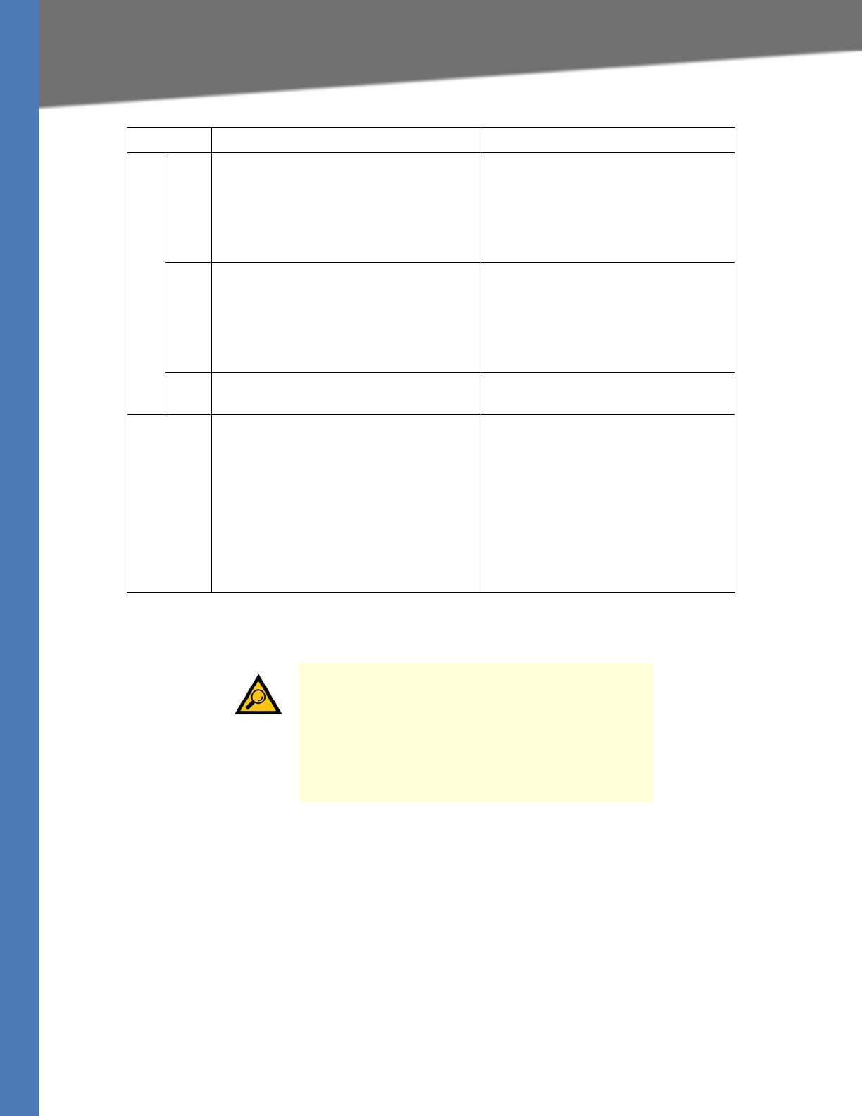
Linksys Voice System Administration Guide 115
Writing an Auto Attendant Script
Configuring the LVS Auto-Attendant
Entering an Auto Attendant Script
1. Connect to the SPA9000 administration web server, and choose Admin access with
Advanced settings. (See ”Connecting to the SPA9000 Administration Web Server,” on
page 24).
2. Click Voice tab > SIP.
3. Scroll down to the Auto Attendant Parameters section.
4. Enter your script in the appropriate field: AA Script 1 - 3. For more information, see ”Writing
an Auto Attendant Script,” on page 108.
5. Click Submit All Changes.
goto The Auto Attendant transfers the caller from
one <form> to the other <form>. All
<form>s are identified by the attribute “id”.
The value in the id attribute must be unique;
otherwise, the Auto Attendant selects the
last valid <form> as the transfer-to target.
<goto link= “daytime”>
“daytime” is the id of a <form> entry.
Example: <form id=”daytime”
type=”menu”>
xfer The Auto Attendant performs a blind
transfer of the caller to the target, and then it
ends processing “target = $input” is
equivalent to the input value already passed
by the dialplan. There is no significance to
the name attribute.
<xfer name= “Technical Support” target=
“5000”/>
exit When this action is reached, the Auto
Attendant stops, and the call ends
<exit>
audio The Auto Attendant plays the audio
specified in the “src” attribute. This attribute
must be prompt<n>, with <n> being a
number in the range 1–10. When playing the
audio, the Auto Attendant allows the caller
to interrupt the current prompt by pressing
digits if the bargein attribute is set to “T”. The
Auto Attendant ignores any digits from the
caller if the bargein attribute is set to “F” (the
default value).
<audio src= “prompt1” bargein= “T”/>
TIP: To get started, you may want to copy the default
script from the Voice > SIP page, Auto Attendant
Parameters section, AA Script 1 field. You can paste it
into any word processing application, where you can
see the entire script more easily. Make your changes,
remove any formatting such as line breaks, and paste
the final string into the appropriate AA Script field.
Instruction Description Syntax and Example(s)

Linksys Voice System Administration Guide 116
Configuring the DayTime, NightTime and Weekend/Holiday Auto Attendants
Configuring the LVS Auto-Attendant
Configuring the DayTime, NightTime and Weekend/Holiday
Auto Attendants
You can customize the Auto Attendant with prompts and actions that are appropriate for
different times of day and for the days when the business is closed.
NOTE: By default, the DayTime Auto Attendant is activated, using AA Script 1, an answer delay
of 0 seconds, and no start or end time.
1. Connect to the SPA9000 administration web server, and choose Admin access with
Advanced settings. (See ”Connecting to the SPA9000 Administration Web Server,” on
page 24).
2. Click Voice tab > SIP.
3. Scroll down to the Auto Attendant Parameters section.
4. Proceed as needed:
• To set up the DayTime Auto Attendant:
–DayTime AA: Choose yes from the drop-down list.
–DayTime AA Script: Choose 1, 2, or 3 from the drop-down list.
–DayTime: Enter the start and end times in 24-hour format
SYNTAX: start=hh:mm:ss;end=hh:mm:ss
EXAMPLE: start=08:30:00;end=18:00:00
In this example, the business hours begin at 8:30 a.m. and end at 6:00 p.m.
NOTE: When you enter the DayTime setting, you are in effect also setting the
nighttime hours. There is no separate field for NightTime start and end times.
–DayTime Answer Delay: Enter the number of seconds that the Auto Attendant waits
before answering a call. This setting is useful when the Auto Attendant is used as a
backup tool for a live answerer. For example, assume that the Contact List includes
both the receptionist and the Auto Attendant. You might set the Answer Delay to 12
seconds. If the receptionist does not answer within that time, then the Auto
Attendant answers the call.
• To set up the NightTime Auto Attendant:
–NightTime AA: Choose yes from the drop-down list.
–NightTime AA Script: Choose 1, 2, or 3 from the drop-down list.
–DayTime: Define the daytime hours, which also defines the nighttime hours. Enter
the start and end times in 24-hour format
SYNTAX: start=hh:mm:ss;end=hh:mm:ss
EXAMPLE: start=08:30:00;end=18:00:00
In this example, the daytime hours begin at 8:30:00 a.m. and end at 6:00:00 p.m.
Nighttime hours begin at 6:00:01 p.m. and end at 8:29:59 a.m.

Linksys Voice System Administration Guide 117
Configuring Dial Plans for the Auto Attendant
Configuring the LVS Auto-Attendant
–NightTime Answer Delay: Enter the number of seconds that the Auto Attendant waits
before answering a call. Typically the nighttime delay is set to 0 because no one is on
site to answer calls.
• To set up the Weekend/Holiday Auto Attendant:
–Weekend/Holiday AA: Choose yes from the drop-down list.
–Weekend/Holiday AA Script: Choose 1, 2, or 3 from the drop-down list.
–Weekends/Holidays: Define the weekend and holidays, using the following syntax:
[wk=n1[,ni];][hd=mm/dd/yyyy|mm/dd/yyyy-mm/dd/yyyy[,mm/dd/yyyy|mm/dd/yyyy-mm/
dd/yyyy];]
*
For weekends, the syntax is wk=n1[,ni]. In place of n1, specify first day of the
weekend (1 for Monday, 2 for Tuesday, and so on). If the weekend lasts more
than one day, specify the final day of the weekend in place of n1. Separate the
values with a comma.
*
For holidays, specify each date in mm/dd or mm/dd/yyyy format (the year is
optional). Separate the dates with a comma, or indicate a range of dates with
a dash.
EXAMPLE: wk=6,7;hd=1/1,2/21/2006,5/30/2006,12/19/2006-12/30/2006
In this example, the weekend is defined as Saturday and Sunday. The holidays are
Jan. 1 indefinitely; Feb. 21, 2006; May 30, 2006; and Dec. 19-30, 2006.
–Weekend/Holiday Answer Delay: Enter the number of seconds that the Auto
Attendant waits before answering a call. Typically the weekend delay is set to 0
because no one is on site to answer calls.
5. Click Submit All Changes.
Configuring Dial Plans for the Auto Attendant
Each Auto Attendant script refers to an Auto Attendant Dial Plan to determine how to process
the DTMF digits that are entered by the caller. You can define two dial plans on the Voice > SIP
page, Auto Attendant Parameters section, AA Dial Plan 1 and AA Dial Plan 2 fields.
EXAMPLE 1, Default AA Dial Plan 1: (10x|xxx.)
EXAMPLE 2: (<x:500x>|408555xxxx|xxxxx)”, “(<1:1002>|<2:21111>|<3:3333>|xxxxx)
In this example, when the user inputs DTMF digits, AA parses them using the dial plan first, then
the parsing result is directed to the AA script menu instruction.

Linksys Voice System Administration Guide 118
8Requirements for Localization
Localization
Localization
You can localize your LVS with the language files, tones, and ring patterns that are appropriate
for your region.
•”Requirements for Localization,” on page 118
•”Localizing the SPA9000 Auto Attendant Prompts,” on page 118
•”Local Time Configuration,” on page 120
•”Configuring the SPA9000 and SPA9xx Call Progress Tones,” on page 120
•”Localizing the SPA400 Voice Mail Prompts,” on page 125
•”Localizing the SPA400 Call Disconnect Tones,” on page 126
•”Localizing the SPA400 Caller ID Method,” on page 128
Note For instructions about localizing the phone display, see the Linksys
Phone Administration Guide, which is available at www.linksys.com.
Requirements for Localization
You need TFTP server software to localize the SPA9000.
Localizing the SPA9000 Auto Attendant Prompts
The default Auto Attendant prompts are in English. You can localize your system by
downloading and installing the appropriate language files for your region. Store these prompts
on a TFTP/HTTP/HTTPS server, and the SPA9000 will download the files at the device boot up
time.
The set of files includes the following types of prompts:
• Prompt 1: Greets the caller and prompts for an extension number
• Prompt 2: Notifies the caller that the call is being forwarded
• Prompt 3: Notifies the caller of an invalid extension
• Prompt 4: Good-bye
• Prompt 5: Greets the caller with specific prompts for General Information, Sales, and
Support.
• Prompt 6: Notifies the caller that the office is currently closed and prompts for an
extension number.

Linksys Voice System Administration Guide 119
Localizing the SPA9000 Auto Attendant Prompts
Localization
Note The Auto Attendant prompt files must be encoded in G.711u and must
have a total file size (message and header) of 94.5 seconds or less.
1. Download the prompts:
a. Start Internet Explorer, enter the address of the EMEA Portal (www.linksys-voip.eu or
www.linksys-itsp.com), and log on.
b. In the left navigation pane, select the following links: FW & Tools > LVS > Localization
> SPA9000 Auto Attendant prompts.
c. Select the download link for the language that you want. Repeat as needed for up to
nine languages.
NOTE: North American partners can find localization files in the Utilities area of the Linksys
Partner Connection.
2. Store the downloaded files on a TFTP/HTTP/HTTPS server.
3. Configure the SPA9000 to download the files from the server:
a. Connect to the SPA9000 administration web server, and choose Admin access with
Advanced settings. (See ”Connecting to the SPA9000 Administration Web Server,” on
page 24).
b. Click Voice tab > the SIP tab.
c. Scroll down to the Auto Attendant Parameters area of the page.
d. In the AA Prompts URL field, enter the script for the server, path, and prompt file names.
SYNTAX:
serv=scheme://server_addr[:port]/root_path;[p1={prompt1 file path name};][p2={prompt2 file
path name};][p3={prompt3 file path name};][p4={prompt4 file path name};][p5={prompt5 file
path name};][p6={prompt6 file path name};][p7={prompt7 file path name};][p8={prompt8 file
path name};][p9={prompt9 file path name};][p10={prompt10 file path name};]
EXAMPLE:
serv=tftp://192.168.2.150/root/test/;p1=fr_1.wav; p2=fr_2.wav;p3=fr_3.wav;p4=none;
NOTE:
– scheme: Enter one of the following values: tftp, http, or https.
– port: The default ports are 69 for tftp, 80 for http, and 443 for https.
– root_path can be empty.
– [ ] denotes an optional item.
– If the prompt file name is none, the corresponding prompt currently saved in the
flash is erased.
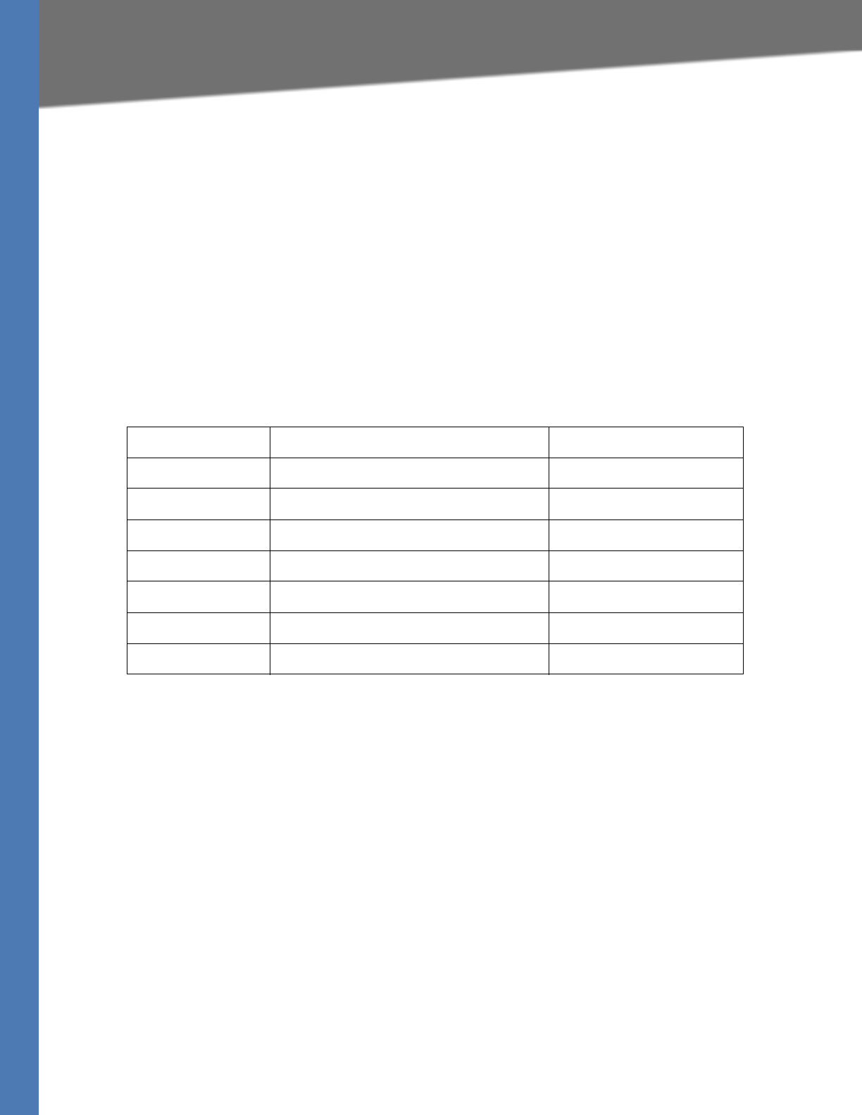
Linksys Voice System Administration Guide 120
Local Time Configuration
Localization
4. Click Submit All Changes.
The prompts are downloaded when the SPA9000 boots up. If a prompt has already been
downloaded from the given URL, the download is not performed.
5. To verify that the prompts are localized, make a call to the Auto Attendant. From an internal
phone, you can press the Setup button, then press 1 - Directory, then 2 - Corporate
Directory, and then scroll down to find and select the number for the Auto Attendant.
Local Time Configuration
You will need to localize the date, time, and daylight saving time rule. See ”Setting the Date and
Time,” on page 27 and ”Configuring Daylight Saving Time,” on page 27. Use the following table
to find the correct Daylight Saving Time Rules for EMEA and Australia.
Configuring the SPA9000 and SPA9xx Call Progress Tones
Call progress tones, such as dial tone and reorder, indicate the call progress to the users. You
can configure your SPA9000 and your SPA9xx phones to use the appropriate call progress tones
for your region.
1. Localize the tones for the SPA9000:
a. Start Internet Explorer, and then enter the IP address of the SPA9000. Click Admin Login
and then click Advanced.Connect to the SPA9000 administration web server, and
choose Admin access with Advanced settings. (See ”Connecting to the SPA9000
Administration Web Server,” on page 24).
b. Click Voice tab > Regional.
c. In the Call Progress Tones section, enter the values from Table 3-1 into the corresponding
fields.
d. Click Submit All Changes.
2. Localize the tones for the phones:
Country Daylight Saving Time Rule Time Zone
Australia (ACST) start=4/1/7/3;end=10/1/7/2;save=-1 GMT+10:30
Australia (AEST) start=4/1/7/3;end=10/1/7/2;save=-1 GMT+11
Australia (AWST) start=3/-1/7/3;end=10/-1/7/2;save=¬1 GMT+09:00
France start=3/-1/7/2;end=10/-1/7/2;save=1 GMT+1
Germany start=3/-1/7/2;end=10/-1/7/2;save=1 GMT+1
Spain start=3/-1/7/2;end=10/-1/7/2;save=1 GMT+1
UK/Ireland start=3/-1/7/2;end=10/-1/7/2;save=1 GMT
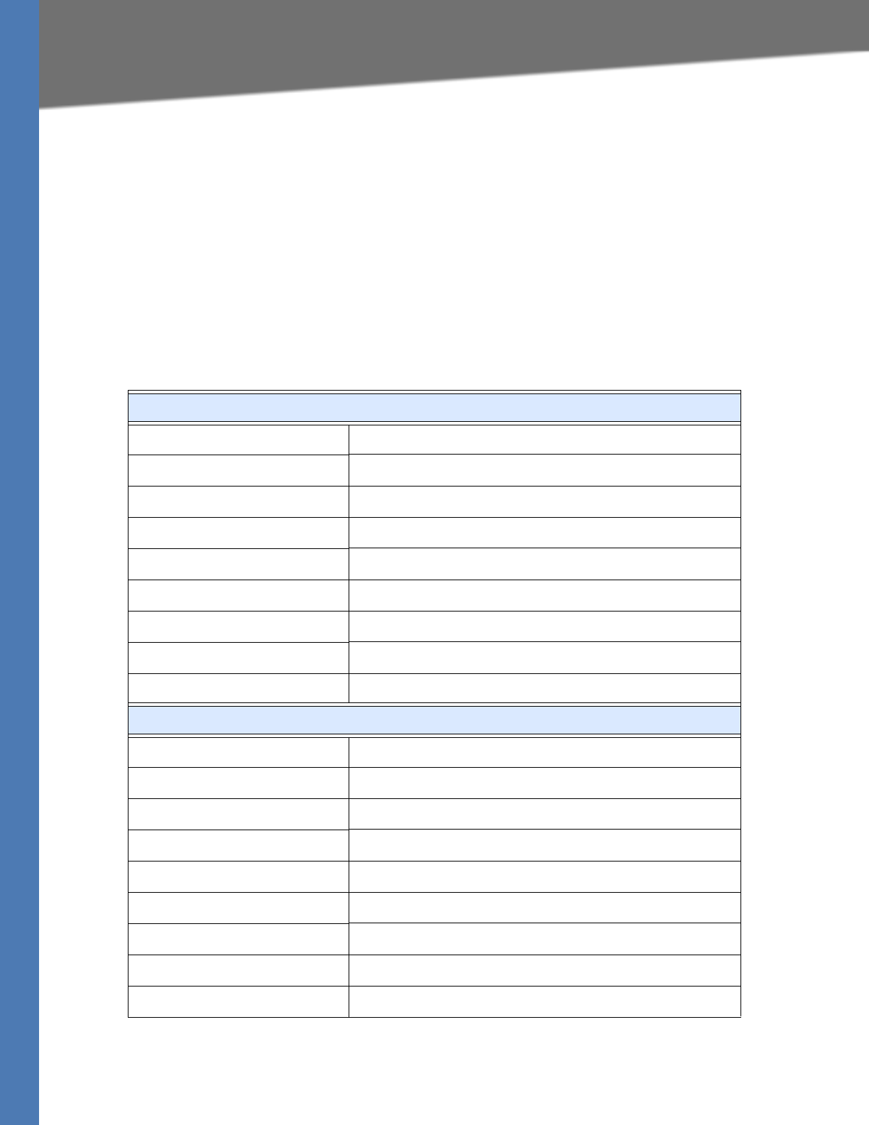
Linksys Voice System Administration Guide 121
Configuring the SPA9000 and SPA9xx Call Progress Tones
Localization
a. Click the PBX Status link.
b. Find the phone that you want to configure, and then click the hyperlink in the IP Address
column.
c. Click Regional.
d. In the Call Progress Tones section, enter the values from Table 8-1 into the corresponding
fields.
e. Click Submit All Changes.
f. Repeat this step as needed for each phone.
Table 8-1 SPA9000 Call Progress Tones by Country
Australia
Dial Tone 400@-19,425@-19;10(*/0/1+2)
Outside Dial Tone 420@-16;10(*/0/1)
Prompt Tone 520@-19,620@-19;10(*/0/1+ 2)
Reorder Tone 425@-19;*(2.5/.5)
Off Hook Warning Tone 480@-10,620@0;10(.125/.125/1+2)
Ring Back Tone 400@-19,425@-19;*(.4/.2/1+2,.4/2/1+2)
Busy Tone 425@-16;10(.375/.375/1)
Call Waiting Tone 400@-20;30(0.1/2/1)
Confirm Tone 600@-16;1(.25/.25/1)
Denmark
Dial Tone 425@-10;*(*/0/1)
Outside Dial Tone 425@-16;10(*/0/1)
Prompt Tone 425@-19,620@-19;*(*/0/1+2)
Reorder Tone 425@-10;*(0.25/0.25/1)
Off Hook Warning Tone 425@-10;*(.2/.2/1,.2/.6/1)
Ring Back Tone 425@-10;*(1/4/1)
Busy Tone 425@-10;10(0.25/0.25/1)
Call Waiting Tone 425@-20;30(0.2/0.2/1,0.2/3.6/1,0.2/0.2/1,0.2/0/1)
Confirm Tone 425@-16;1(.25/.25/1)
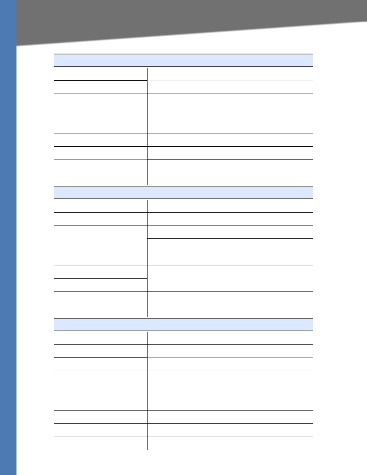
Linksys Voice System Administration Guide 122
Configuring the SPA9000 and SPA9xx Call Progress Tones
Localization
France
Dial Tone 440@-10;*(*/0/1)
Outside Dial Tone 440@-16;10(*/0/1)
Prompt Tone 440@-19,620@-19;*(*/0/1+2)
Reorder Tone 440@-10;*(.5/.5/1)
Off Hook Warning Tone 425@-10;*(.2/.2/1,.2/.6/1)
Ring Back Tone 440@-10;*(1.5/3.5/1)
Busy Tone 440@-10;10(.5/.5/1)
Call Waiting Tone 440@-20;30(.175/.175/1,.175/3.5/1)
Confirm Tone 440@-16;1(.25/.25/1)
Germany
Dial Tone 425@-10;10(*/0/1)
Outside Dial Tone 425@-13,400@-13;10(*/0/1+2)
Prompt Tone 440@-19,620@-19;30(*/0/1+2)
Reorder Tone 440@-10;*(.5/.5/1)
Off Hook Warning Tone 425@-10;*(.2/.2/1,.2/.6/1)
Ring Back Tone 440@-10;10(1.5/3.5/1)
Busy Tone 425@-10;10(0.48/0.48/1)
Call Waiting Tone 425@-20;30(0.2/0.2/1,0.2/5/1)
Confirm Tone 440@-16;1(.25/.25/1)
Ireland
Dial Tone 400@-10;*(*/0/1)
Outside Dial Tone 425@-16;10(*/0/1)
Prompt Tone 425@-19,620@-19;*(*/0/1+2)
Reorder Tone 425@-10;*(0.25/0.25/1)
Off Hook Warning Tone 425@-10;*(.2/.2/1,.2/.6/1)
Ring Back Tone 425@-10;(0.4/0.2/1,0.4/2/1)
Busy Tone 425@-10;10(0.5/0.5/1)
Call Waiting Tone 425@-20;30(0.18/0.2/1,0.2/4.5/1)
Confirm Tone 425@-16;1(.25/.25/1)

Linksys Voice System Administration Guide 123
Configuring the SPA9000 and SPA9xx Call Progress Tones
Localization
Italy
Dial Tone 425@-10;*(0.2/0.2/1,0.6/1/1)
Outside Dial Tone 425@-16;10(0.2/0.2/1,0.6/1/1)
Prompt Tone 425@-19,620@-19;*(*/0/1+2)
Reorder Tone 425@-10;*(0.2/0.2/1)
Off Hook Warning Tone 425@-10;*(.2/.2/1,.2/.6/1)
Ring Back Tone 425@-10;*(1/4/1)
Busy Tone 425@-10;10(0.5/0.5/1)
Call Waiting Tone 425@-20;30(0.4/0.1/1,0.25/0.1/1,0.15/14/1)
Confirm Tone 425@-16;1(.25/.25/1)
Netherlands
Dial Tone 425@-10;*(*/0/1)
Outside Dial Tone 425@-16;10(*/0/1)
Prompt Tone 425@-19,620@-19;*(*/0/1+2)
Reorder Tone 425@-10;*(0.25/0.25/1)
Off Hook Warning Tone 425@-10;*(.2/.2/1,.2/.6/1)
Ring Back Tone 425@-10;*(1/4/1)
Busy Tone 425@-10;10(.5/.5/1)
Call Waiting Tone 425@-20;30(0.5/9.5/1)
Confirm Tone 425@-16;1(.25/.25/1)
Norway
Dial Tone 425@-10;*(*/0/1)
Outside Dial Tone 425@-16;10(*/0/1)
Prompt Tone 425@-19,620@-19;*(*/0/1+2)
Reorder Tone 425@-10;*(0.2/0.2/1)
Off Hook Warning Tone 1400@-10;*(0.4/15/1)
Ring Back Tone 425@-10;(1/4/1)
Busy Tone 425@-10;10(.5/.5/1)
Call Waiting Tone 425@-20;30(0.2/0.6/1,0.2/10/1)
Confirm Tone 1400@-16;1(20/0/1)

Linksys Voice System Administration Guide 124
Configuring the SPA9000 and SPA9xx Call Progress Tones
Localization
Portugal
Dial Tone 425@-10;*(*/0/1)
Outside Dial Tone 425@-16;10(*/0/1)
Prompt Tone 425@-19,620@-19;*(*/0/1+2)
Reorder Tone 425@-10;*(.2/.2/1,.2/.2/1,.2/.6/1)
Off Hook Warning Tone 425@-10;*(.2/.2/1,.2/.6/1)
Ring Back Tone 425@-10;*(1/5/1)
Busy Tone 425@-10;10(.5/.5/1)
Call Waiting Tone 425@-20;30(0.2/0.2/1,0.2/5/1)
Confirm Tone 425@-16;1(.25/.25/1)
Spain
Dial Tone 425@-10;*(*/0/1)
Outside Dial Tone 425@-16;10(*/0/1)
Prompt Tone 425@-19,620@-19;*(*/0/1+2)
Reorder Tone 425@-10;*(.2/.2/1,.2/.2/1,.2/.6/1)
Off Hook Warning Tone 425@-10;*(.2/.2/1,.2/.6/1)
Ring Back Tone 425@-10;*(1.5/3/1)
Busy Tone 425@-10;10(.2/.2/1)
Call Waiting Tone 425@-20;30(.175/.175/1,.175/3.5/1)
Confirm Tone 425@-16;1(.25/.25/1)
Sweden
Dial Tone 425@-10;*(*/0/1)
Outside Dial Tone 425@-16;10(*/0/1)
Prompt Tone 425@-19,620@-19;*(*/0/1+2)
Reorder Tone 425@-10;*(0.25/0.75/1)
Off Hook Warning Tone 425@-10;*(.2/.2/1,.2/.6/1)
Ring Back Tone 425@-10;*(1/5/1)
Busy Tone 425@-10;10(0.25/0.25/1)
Call Waiting Tone 425@-20;30(0.5/9.5/1)
Confirm Tone 425@-16;1(.25/.25/1)
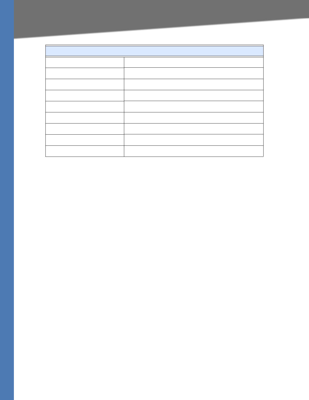
Linksys Voice System Administration Guide 125
Localizing the SPA400 Voice Mail Prompts
Localization
Localizing the SPA400 Voice Mail Prompts
By default, the voice mail system is configured for the English language. You can localize the
system by downloading and installing the appropriate language files for your region.
1. Download the files:
a. Start Internet Explorer, enter the address of the EMEA Portal (www.linksys-voip.eu or
www.linksys-itsp.com), and log on.
b. In the left navigation pane, select the following links: FW & Tools > LVS > Localization
> SPA400 Voice mail prompts.
c. Select the download link for the language that you want.
NOTE: For SPA400 Firmware versions above 1.0.1.3, download the PCM format of the
files.
d. Save the sounds.zip file.
NOTE: North American partners can find localization files in the Utilities area of the Linksys
Partner Connection.
2. Extract the files:
a. Use WinZip to open the sounds.zip file.
b. Click Extract on WinZip toolbar.
c. Select the Desktop or other temporary destination, select the Use folder names check
box, and then click Extract.
A progress bar appears as the files are extracted. The Sounds folder appears in the
selected location.
UK
Dial Tone 350@-10;440@-10;*(*/0/1+2)
Outside Dial Tone 425@-16;10(*/0/1)
Prompt Tone 400@-19,620@-19;*(*/0/1+2)
Reorder Tone 400@-10;*(0.4/0.35/1,0.225/0.525/1)
Off Hook Warning Tone 425@-10;*(.2/.2/1,.2/.6/1)
Ring Back Tone 400@-10;(0.4/0.2/1,0.4/2/1)
Busy Tone 400@-10;10(0.375/0.375/1)
Call Waiting Tone 400@-20;30(0.1/2/1)
Confirm Tone 400@-16;1(20/0/1)

Linksys Voice System Administration Guide 126
Localizing the SPA400 Call Disconnect Tones
Localization
3. Move the files to the SPA400 USB drive to replace the existing voice prompts:
a. Power off the SPA400 by removing the power cord, and then remove the USB drive.
b. Insert the SPA400 USB drive into a USB port on the PC where you extracted the files.
c. When the USB Disk window appears, click Open folder to view files using Windows
Explorer, and then click OK. The USB drive contains the spa400vm folder.
NOTE: If the USB Disk window does not appear, use Windows Explorer to navigate to the
USB disk drive (usually Drive E).
d. Open spa400vm\var\lib. The window displays the lib contents, including the sounds
folder.
e. If desired, make a backup copy of the existing sounds folder.
NOTE: You are not overwriting any user message files in this procedure. However, it is a
good practice to make a backup copy of your files before doing any upgrades.
f. Move the new sounds folder into spa400vm\var\lib on the USB drive. When the Confirm
Folder Replace window appears, click Yes to Al l.
g. Remove the USB drive from the PC and insert it into the SPA400.
h. Power on the SPA400.
4. Place a test call to the voice mail system to confirm that the new language prompts are
used.
Localizing the SPA400 Call Disconnect Tones
One important aspect of VoIP-PSTN integration is the Call Disconnect operation. This operation
allows the gateway to detect that the call has been terminated on the other end, so the local
line hangs up automatically. Detecting the tone cadence of the Call Disconnect signal is a
trigger for closing the loop.
Each country has its own Call Disconnect Signal tone which needs to be configured on the
SPA400 Tone page.
Note This feature is available in SPA400 firmware version 1.0.1.4.

Linksys Voice System Administration Guide 127
Localizing the SPA400 Call Disconnect Tones
Localization
1. Start Internet Explorer, enter the IP address of the SPA400, and log on.
2. Click the Tone tab.
3. Enter the appropriate settings for your country, as listed in Table 8-2, ‘Call Processing Tones,”
on page 127.
Table 8-2 Call Processing Tones
4. Click Save Settings.
Country
First Tone 2nd
(optional)
3rd
(optional)
4th
(optional)
Repeat
Count
On
(ms)
Off
(ms)
On
(ms)
Off
(ms)
On
(ms)
Off
(ms)
On
(ms)
Off
(ms)
Australia 375 375 375 375 5
Denmark 450 450 250 250 1
France 500 500 1
Germany 250 250 1
Ireland 500 500 1
Italy 200 200 1
Netherlands 180 330 180 330 2
Norway 200 200 1
Portugal 200 200 1
Spain 200 200 200 200 200 600 2
Sweden 250 750 1
UK 400 350 225 525 2
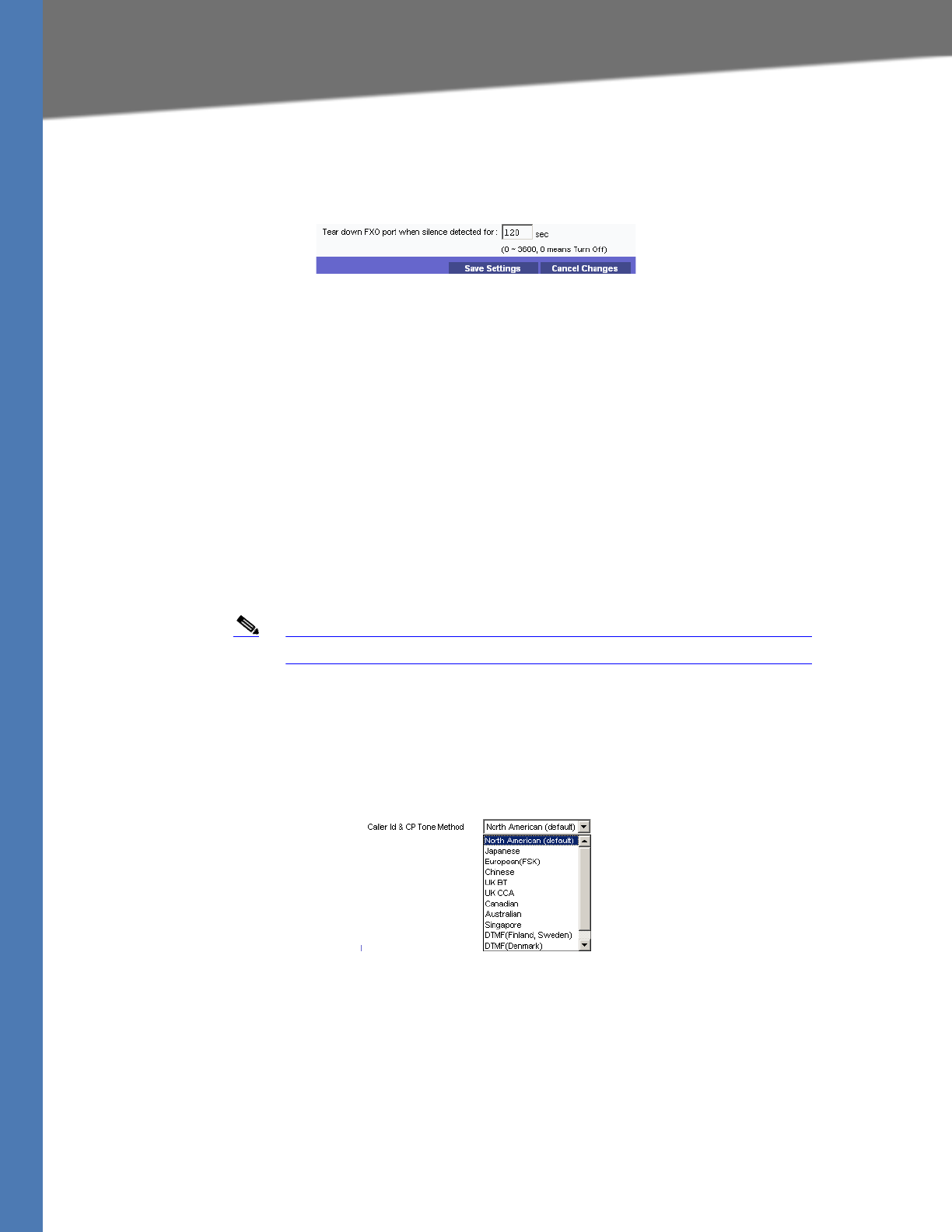
Linksys Voice System Administration Guide 128
Localizing the SPA400 Caller ID Method
Localization
5. On the menu, click Setup > Voice.
6. Scroll down to the Tear Down FXO port when silence period detected for field, and enter: 0
Refer to the following illustration.
7. Click Save Settings.
8. To restart the SPA400, complete the following steps:
a. Click Administration > Reboot.
b. Click the Restart System button.
c. When the confirmation message appears, click OK. The SPA400 reboots.
d. When the Reboot OK. Go to Setup page? message appears, click OK.
Localizing the SPA400 Caller ID Method
You need to identify the caller ID method to use in your country.
Note This feature is available in SPA400 firmware version 1.0.1.4.
1. Click Setup tab > Voice.
2. Scroll down to the Line Settings section.
3. From the Caller Id and CP Tone Method drop-down list, choose your region.
NOTE: In the United Kingdom, choose UK BT or UK CCA. In the rest of Europe, choose
European (FSK).
4. Click Save Settings.
5. To restart the SPA400, complete the following steps:
a. Click Administration > Reboot.
b. Click the Restart button.

Linksys Voice System Administration Guide 129
Localizing the SPA400 Caller ID Method
Localization
c. When the confirmation message appears, click OK. The SPA400 reboots.
d. When the Reboot OK message appears, click OK.
6. To verify your progress, make a call from outside to any of the PSTN lines connected to the
SPA400 (make sure that CID is enable in your PSTN line). In the ringing SPA phone display
you should now be able to see the number from the calling number.

Linksys Voice System Administration Guide 130
ATechnology Background
Advanced Topics in LVS Administration
This appendix provides technical information that is useful to individuals who want a better
understanding of how the LVS works.
•”Technology Background,” on page 130
•”SPA9000 Architecture,” on page 134
•”SIP-NAT Interoperation,” on page 135
•”Advanced Call Control and Routing,” on page 137
•”Configuring Vertical (Supplementary) Service Codes,” on page 137
•”Advanced Topics for SPA400 Voice Mail Service,” on page 141
•”Remote Provisioning Features,” on page 145
Technology Background
This section provides background information about the technology and protocols used by the
SPA9000 system. It includes the following topics:
•”Session Initiation Protocol,” on page 130
•”SPA9000 Media Proxy,” on page 132
•”Using the SPA9000 with a Firewall or Router,” on page 133
•”SPA400 SIP-PSTN Gateway,” on page 133
Session Initiation Protocol
The LVS is implemented using open standards, such as Session Initiation Protocol (SIP),
allowing interoperation with all ITSPs supporting SIP. Figure A-1 illustrates a SIP request for
connection to another subscriber in the network. In the SIP protocol, the requestor of the
session is called the user agent server (UAS), while the receiver of the request is called the user
agent client (UAC).
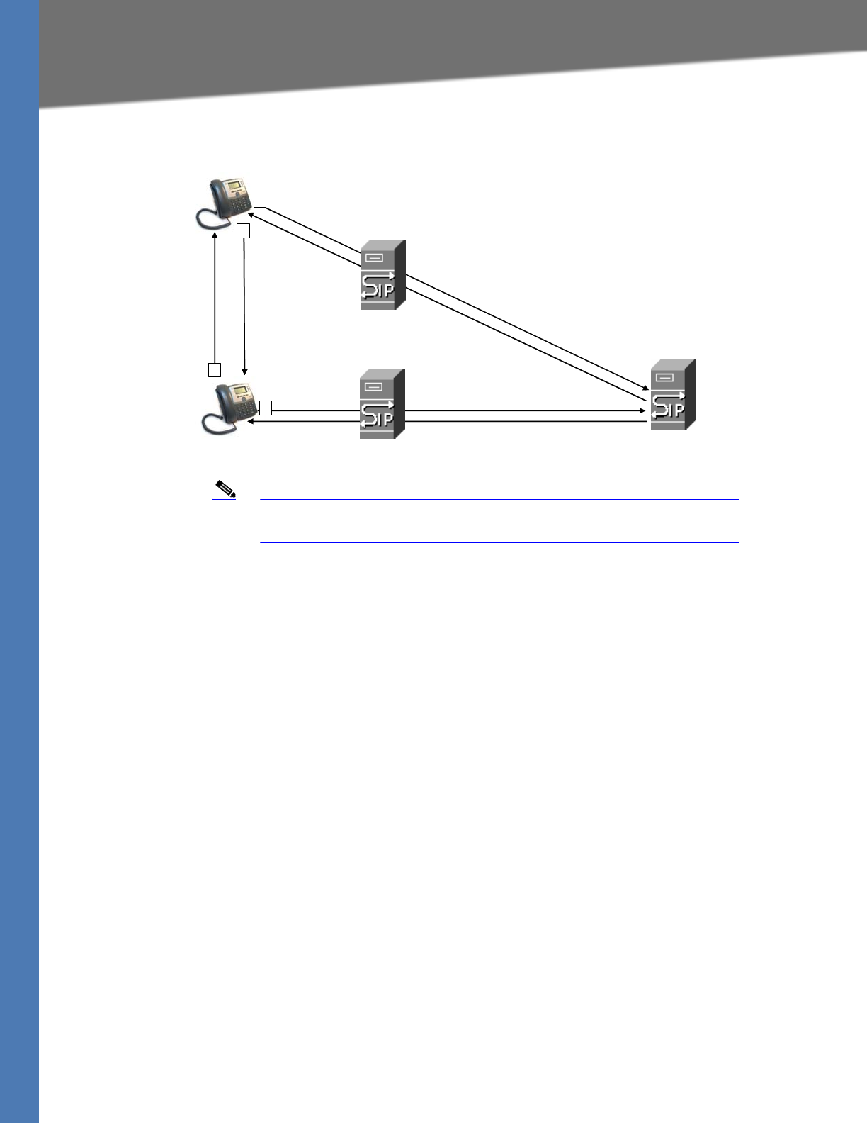
Linksys Voice System Administration Guide 131
Technology Background
Figure A-1 SIP Requests and Responses
Note In this manual, the term client station is used to describe any SIP UA
(including IP phones) that registers with the SPA9000.
In a SIP VoIP network, when the SIP proxy receives a request from a client station (UAS) for a
connection and it does not know the location of the UAC, it forwards the message to another
SIP proxy in the network. Once the UAC is located and the response is routed back to the UAS, a
direct peer-to-peer session is established between the two UAs. The actual voice traffic is
transmitted between UAs over dynamically assigned ports using the Real-time Protocol (RTP).
In Figure A-2, UserA and UserB are client stations (UAs) that register over the local area network
to which the SPA9000 PBX is connected. When UserA calls UserB, the SPA9000 acts as a SIP
proxy and establishes a session between the two UAs. After the session is established, RTP
traffic flows directly between the two client stations.
SIP UA
SIP UA
SIP Proxy
SIP Proxy
RTP
1
2
3
4
SIP Proxy

Linksys Voice System Administration Guide 132
Technology Background
Figure A-2 SPA9000 as a SIP Proxy
When a user picks up the handset in an LVS system, the SPA9000 collects DTMF digits from a
touchtone analog telephone or the locally connected SPA900 Series IP phones. Unless the call
is for a local client station, the SPA9000 system sends the full number in a SIP INVITE message to
another SIP proxy server for further call processing.
To minimize dialing delay, a dial plan is maintained that is matched against the cumulative
number entered by the user. Invalid phone numbers that are not compatible with the dial plan
are detected and the user is alerted using a configurable tone (reorder) or announcement.
Figure A-2 also illustrates connectivity between the SPA9000 and the ITSP over the Internet.
When UserA calls UserC, the SPA9000 directs the request to the SIP proxy at the ITSP, which is
then responsible for routing the request to UserC. Even after the SIP session is established, the
SPA9000 continues to direct RTP packets between UserA and the ITSP.
SPA9000 Media Proxy
To address this possible security issue, the SPA9000 can also function as a media (RTP) proxy.
This option forces RTP traffic destined for the Internet (or IP WAN) to be directed to the
SPA9000, which then directs it to the remote UA. This configuration may simplify firewall
configuration because the client stations do not require direct access to the Internet through
the firewall.
To enable the media proxy, go to the Voice > SIP page, PBX Parameters section, and set the Force
Media Proxy parameter to True. With the media proxy enabled, when UserA calls User C, the
SPA9000 still acts as the SIP proxy and forwards the request to the SIP server on the ITSP.
However, even after the SIP session is established, the SPA9000 continues to direct RTP packets
between UserA and the ITSP.
Local traffic is not affected by this configuration. When UserA initiates a call to UserB, RTP traffic
still flows directly between the two UAs. The media proxy only affects RTP traffic to a UA
connected through the ITSP.
SIP Proxy with
media proxy enabled
Internet
IP Router (firewall)
Broadband modem
Hub/switch
SPA9000
UserA UserB
UserC
Internet (WAN)
Interface
ITSP
ISP
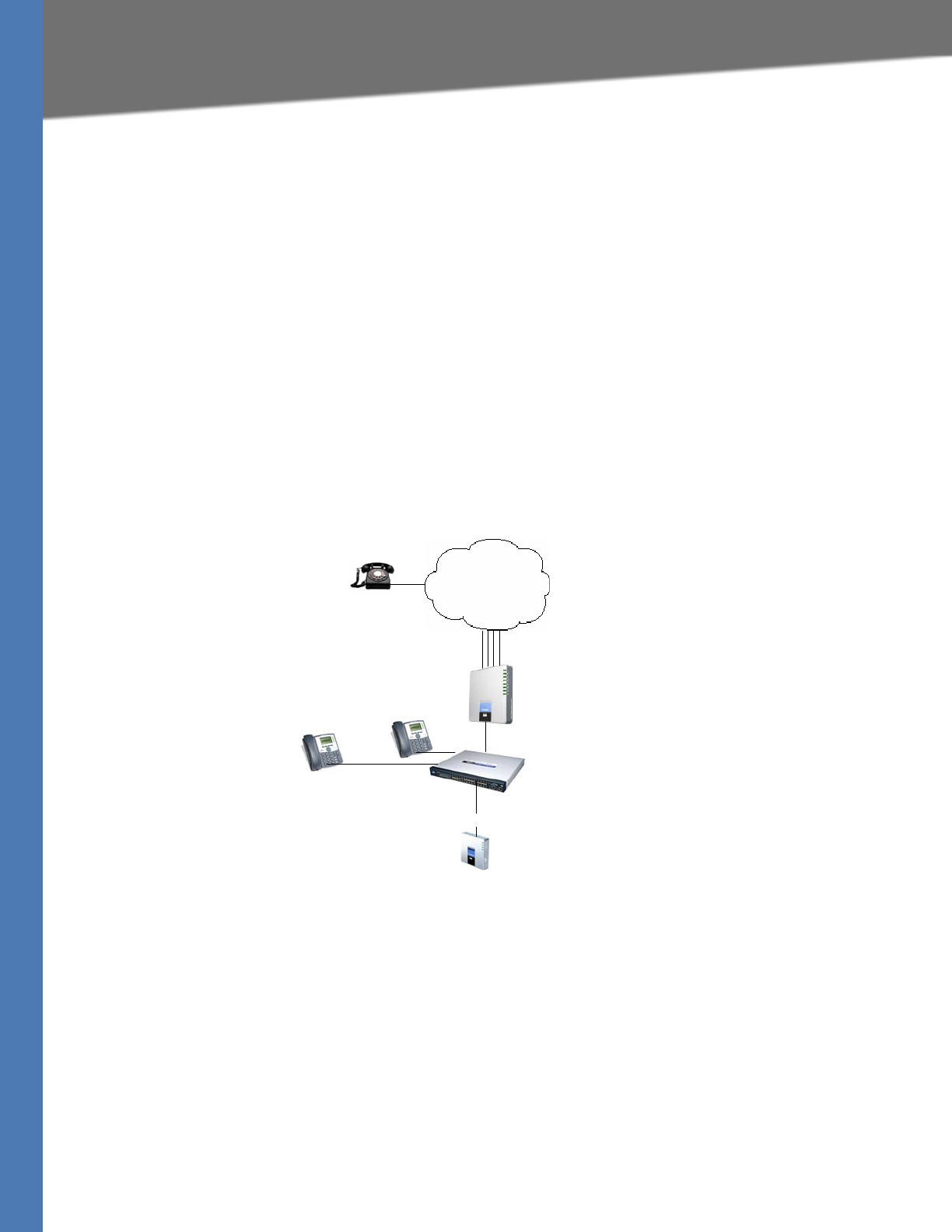
Linksys Voice System Administration Guide 133
Technology Background
Using the SPA9000 with a Firewall or Router
When using the SPA9000 behind a firewall or router, make sure that the following ports are not
blocked:
SIP ports—By default, UDP ports 5060 through 5063
RTP ports—16384 to 16482
Also disable SPI if this function exists on your firewall.
SPA400 SIP-PSTN Gateway
When a local user on the SPA9000 network initiates a call to a PSTN subscriber, the SPA400 acts
as the SIP-PSTN gateway, which converts the SIP and RTP media packets into the appropriate
signal for transmission to the PSTN switch. For example, if UserA calls UserD, the SIP request is
routed by the SIP proxy in the SPA9000 to the SPA400 (see Figure A-3).
Figure A-3 The SPA400 as a SIP-PSTN Gateway
The SPA400 then converts the SIP and RTP packets it receives from UserA and the signals it
receives from the PSTN switch.
SIP Proxy
Switch
SPA9000
UserA UserB
SPA400
1 to 4 DID lines
SIP-PSTN
Gateway
UserD
Internet (WAN) Interface
PSTN
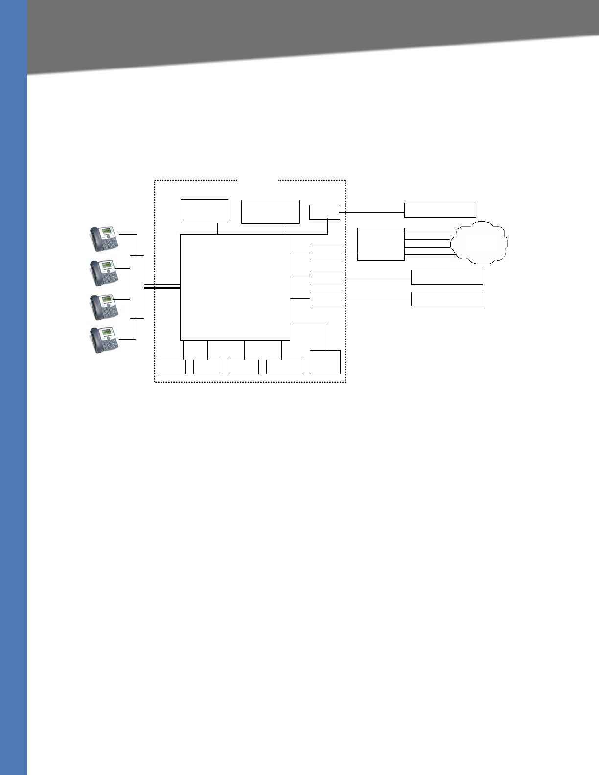
Linksys Voice System Administration Guide 134
SPA9000 Architecture
SPA9000 Architecture
This section describes the basic architecture, function, and configuration options for the
SPA9000.
Figure A-4 SPA9000 Architecture
As shown in Figure A-4, the SPA 9000 provides four logical line interfaces, referred to as Line 1,
2, 3, and 4. Each line can be configured with the same or a different ITSP. Each SPA400 also
occupies one line interface. The SPA9000 has five internal clients that register implicitly with the
internal SIP proxy:
• FXS1 (fxs1)
• FXS2 (fxs2)
• Call Park (callpark)
• Auto-Attendant (aa)
• Internal Music Server (imusic)
FXS1 and FXS2 correspond to the two physical FXS ports. The FXS ports can only register with
the local SIP proxy. The Call Park is used to maintain calls that are parked, and AA is a scriptable
auto-attendant application.
imusic
Line 1 ITSP SIP Proxy
(408)111-1000 to 7
(949)111-2000 to 7
(888)111-3000 to 7
ITSP SIP Proxy
ITSP SIP Proxy
SPA9000
aa
PSTN
SPA 400
SIP-PSTN
gateway
(408)111-1111
(408)111-1112
(408)111-1113
(408)111-1114
Line 2
Line 3
Line 4
FXS1
Application
server
Switch
FXS2
SIP Proxy
SIP Registrar
Media (RTP) Proxy
Call
park
Administration
web server
Linksys Voice System Administration Guide 135
SIP-NAT Interoperation
SIP-NAT Interoperation
If the SPA9000 is behind the NAT device, the private IP address of the SPA9000 is not usable for
communications with the SIP entities outside the private network.
Note If the ITSP offers an outbound NAT-Aware proxy, this discovers the
public IP address from the remote endpoint and eliminates the need to
modify the SIP message from the UAC.
The SPA9000 system must substitute the private IP address information with the proper
external IP address/port in the mapping chosen by the underlying NAT to communicate with a
Table A-1 Architectural Components
Architectural Component Function
SIP proxy and Registrar server Accepts registration from client stations and
proxies SIP messages.
Media proxy server Proxies RTP packets between client stations
and proxies SIP messages.
Configuration server Serves configuration files to client stations
and auto configures un-provisioned client
stations.
Application server Supports advanced features such as call
park/pickup, directory, directed call pickup
and group paging, hunt groups, and shared
line appearances.
Internal music source Streams audio files to client stations (both
on-net and off-net).
The FXS1 and FXS2 can optionally be
connected to an external music source to act
as a streaming audio server (SAS). When
working in this mode, each FXS port can
handle up to 10 concurrent calls.
Administration web server Allows configuration and monitoring of the
SPA9000.
ATA with 2 FXS ports Each FXS port can be connected to analog
phones, fax machine, or an external music
source. Each port can support up to two calls
simultaneously. The FXS ports can only
register to the internal proxy server.
Call park The call park is used to maintain calls that are
parked and can handle up to 10 calls
simultaneously
Auto-Attendant AA is a scriptable auto-attendant application
that can handle up to 10 calls simultaneously

Linksys Voice System Administration Guide 136
SIP-NAT Interoperation
particular public peer address/port. For this, the SPA9000 system needs to perform the
following tasks:
• Discover the NAT mappings used to communicate with the peer.
This can be done with the help of an external device, such as a STUN server. A STUN
server responds to a special NAT-Mapping-Discovery request by sending back a
message to the source IP address/port of the request, where the message contains the
source IP address/port of the original request. The SPA9000 system can send this
request when it first attempts to communicate with a SIP entity over the Internet. It then
stores the mapping discovery results returned by the server.
• Communicate the NAT mapping information to the external SIP entities.
If the entity is a SIP Registrar, the information should be carried in the Contact header
that overwrites the private address/port information. If the entity is another SIP UA
when establishing a call, the information should be carried in the Contact header as well
as in the SDP embedded in SIP message bodies. The VIA header in outbound SIP
requests might also need to be substituted with the public address if the UAS relies on it
to route back responses.
• Extend the discovered NAT mappings by sending keep-alive packets.
Because the mapping is alive only for a short period, the SPA9000 system continues to
send periodic keep-alive packets through the mapping to extend its validity as
necessary.
Determining Whether the Router Uses Symmetric or Asymmetric NAT
STUN does not work on routers with symmetric NAT. With symmetric NAT, IP addresses are
mapped from one internal IP address and port to one external, routable destination IP address
and port. If another packet is sent from the same source IP address and port to a different
destination, then a different IP address and port number combination is used. This method is
restrictive because an external host can send a packet to a particular port on the internal host
only if the internal host first sent a packet from that port to the external host.
Note This procedure assumes that a syslog server is configured and is ready
to receive syslog messages. For more information about logging, see
”Collecting System Logs and Debug Information,” on page 31.
1. Make sure you do not have firewall running on your PC that could block the syslog port
(port 514 by default).
2. Connect to the SPA9000 administration web server, and choose Admin access with
Advanced settings. (See ”Connecting to the SPA9000 Administration Web Server,” on
page 24).
3. To enable debugging on the SPA9000, complete the following tasks:
a. Click Voice tab > System.

Linksys Voice System Administration Guide 137
Advanced Call Control and Routing
b. In the Debug Server field, enter the IP address of your syslog server.
NOTE: This address and port number must be reachable from the SPA9000.
c. From the Debug level drop-down list, choose 3.
4. To collect information about the type of NAT your router is using, complete the following
tasks:
a. Click Voice tab > SIP.
b. Scroll down to the NAT Support Parameters section.
c. From the STUN Test Enable field, choose yes.
5. To enable SIP signalling, complete the following task:
a. Click Voice tab > Line N, where N represents the line interface number.
b. In the SIP Settings section, choose full from the SIP Debug Option field.
6. Click Submit All Changes.
7. View the syslog messages to determine whether your network uses symmetric NAT. Look
for a warning header in the REGISTER messages, such as Warning: 399 spa "Full Cone NAT
Detected.”
Advanced Call Control and Routing
•”Configuring Vertical (Supplementary) Service Codes,” on page 137
•”Managing the Outbound Call Routing Groups,” on page 139
•”Configuring Outbound Call Codec Selection Codes,” on page 141
Configuring Vertical (Supplementary) Service Codes
Users can enter vertical (supplementary) service codes, also known as star (*) codes, to activate
special calling features, such as *69 for call return. The LVS is pre-configured with default star
codes, but you can customize them for your site. The codes are automatically appended to the
dial plan.
1. Connect to the SPA9000 administration web server, and choose Admin access with
Advanced settings. (See ”Connecting to the SPA9000 Administration Web Server,” on
page 24).
2. Click Voice tab > Regional.
3. Scroll down to the Vertical Service Activation Codes area or the Vertical Service Announcement
Codes section.
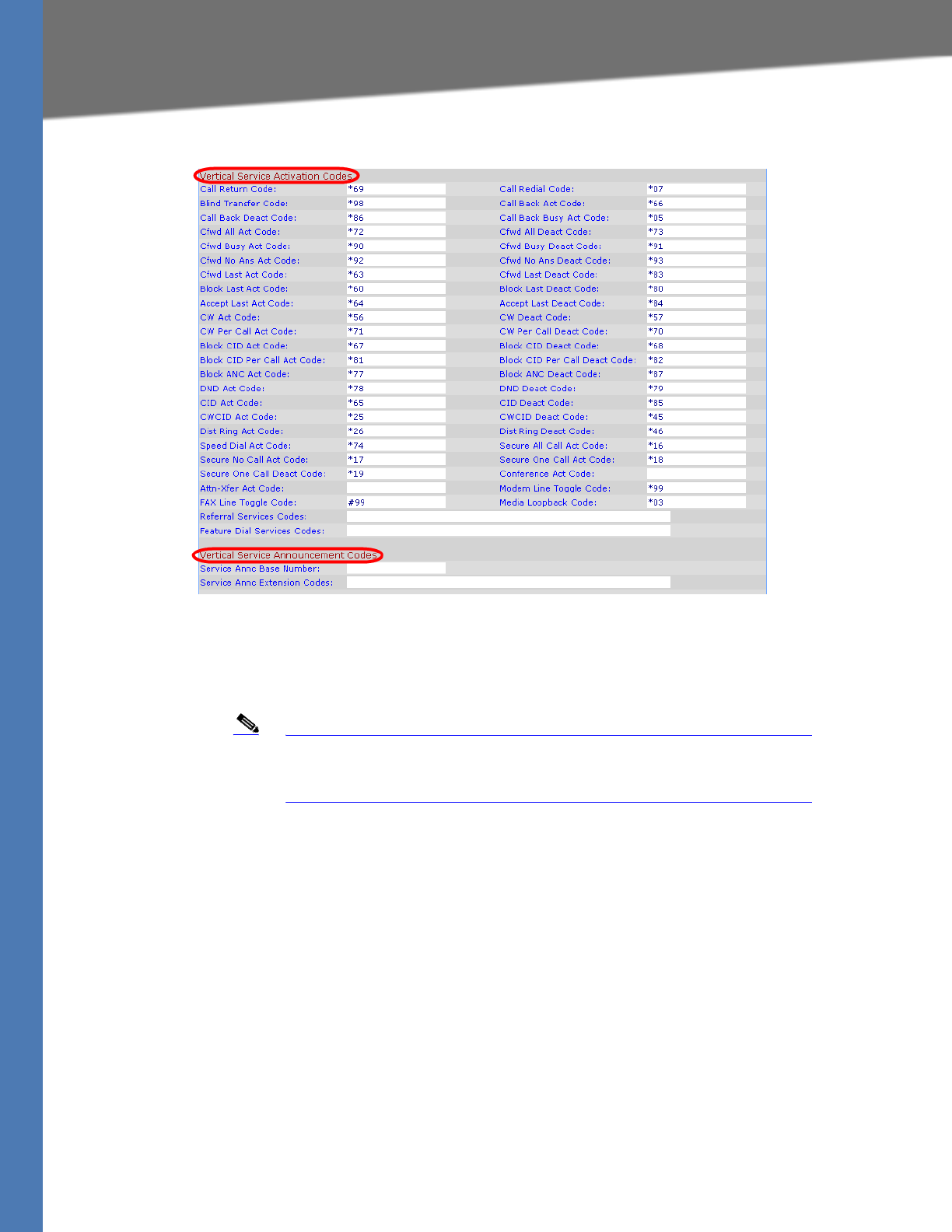
Linksys Voice System Administration Guide 138
Advanced Call Control and Routing
SPA9000 Voice > Regional: Vertical Service Activation Codes, Announcement Codes
4. Edit the codes, as needed.
5. If desired, enter referral services and feature call services codes. For more information, see
Appendix B, "SPA9000 Field Reference," ”Regional page” section on page 176.
Note The * codes should not conflict with any of the other vertical service
codes internally processed by the SPA9000. You can empty the
corresponding *code that you do not want to SPA9000 to process.
6. Click Submit All Changes. For more information about each field, see ”Vertical Service
Activation Codes section,” on page 181.

Linksys Voice System Administration Guide 139
Advanced Call Control and Routing
Managing the Outbound Call Routing Groups
Every station belongs to an outbound call routing group. You can leave all stations in the
default group, or you can assign selected stations to groups for the purpose of routing their
outbound calls to preferred lines.
Call Routing Group Membership
Every station belongs to one or more of the following call routing groups:
•Default Group: The Default Group includes any station that is not assigned to another
group.
USE CASE EXAMPLE: Non-sales personnel remain in this group.
•Group 1 -4: Groups 1-4 include the stations that are identified in the Group 1 User ID...
Group 4 User ID fields. If the user ID matches more than one group, then the smallest
group number is assumed. You can add a station to a group by entering the user ID, or
you can add a range of stations by entering numbers and wildcard characters.
USE CASE EXAMPLE: The administrator enters the station user IDs for each group in the
following fields:
–Group 1 User ID: 11?
This group includes stations 110 through 119, which are used by the New York team.
–Group 2 User ID: 101, 102, 103
This group includes stations 101, 102, and 103, which are used by the Los Angeles
team.
–Group 3 User ID: 203, 204, 209
This group includes stations 203, 204, and 209, which are used by the London team.
A company has three sales teams (New York, Los Angeles, and
London) that work in an office in New York City. Calls from the New
York sales team need to go out through the local PSTN lines. Calls
from the Los Angeles team need to go out through an ITSP account
with a Los Angeles DID number. Likewise, calls from the London sales
team need to go out through an ITSP account with a London DID
number. During peak call periods, if a preferred line is unavailable,
calls can be routed through the general use ITSP account.
The LVS administrator creates three call routing groups and assigns
client stations to them. For each group, the administrator also
defines the preferred line interfaces, in order.

Linksys Voice System Administration Guide 140
Advanced Call Control and Routing
Call Routing Group Line Preference
After you create a group, you must enter a list of lines, in the preferred order. When a group
member places a call, the SPA9000 chooses the first line in the list. If it is unavailable, the
SPA9000 chooses the next line, and so on, until an available line is found. To enter the lines, type
the line numbers in the desired order, separated by commas.
Note The field cannot be left blank.
USE CASE EXAMPLE: The administrator enters the line preferences for each group in
the following fields:
–Group 1 Line: 2,1
Outbound calls from Group 1 (New York) go out through Line 2 (SPA400 connected
to PSTN lines). If that line interface is not available, calls can go out through Line 1
(general use ITSP account).
–Group 2 Line: 3,1
Outbound calls from Group 2 (Los Angeles) go out through Line 3 (ITSP account with
a Los Angles DID number). If that line interface is not available, calls can go out
through Line 1 (general use ITSP account).
–Group 3 Line: 4,1
Outbound calls from Group 3 (London) go out through Line 4 (ITSP account with a
London DID number). If that line interface is not available, calls can go out through
Line 1 (general use ITSP account).
Creating or Modifying an Outbound Call Routing Group
1. Connect to the SPA9000 administration web server, and choose Admin access with
Advanced settings. (See ”Connecting to the SPA9000 Administration Web Server,” on
page 24).
2. Click Voice tab > SIP.
3. Scroll down to the PBX Parameters section.
4. In the Group 1 User ID field, or other desired Group User ID field, enter the user IDs for the
stations that you want to include. For more information, see ”Call Routing Group
Membership,” on page 139.
5. In the Group 1 Line field, or other desired Group Line field, enter the line interfaces in the
order of preference. For more information, see ”Call Routing Group Line Preference,” on
page 140.
NOTE: As you make your entries, read the field labels to distinguish between the fields for
Group 1 User ID ... Group 4 User ID and Group 1 Line ... Group 4 Line.
6. Click Submit All Changes.
7. To verify your progress, place a call to a phone that has caller ID, and confirm that the
expected number appears.
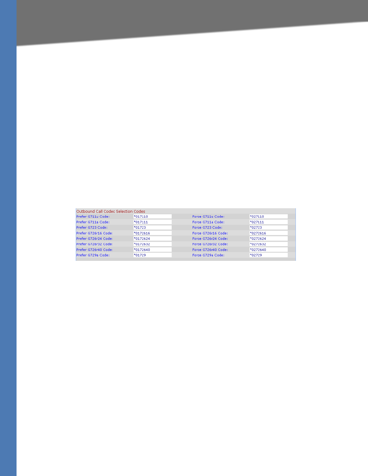
Linksys Voice System Administration Guide 141
Advanced Topics for SPA400 Voice Mail Service
Configuring Outbound Call Codec Selection Codes
A user can enter a code selection code before dialing a number, to choose the preferred codec
for the associated call.The LVS is pre-configured with default codec selection codes, but you
can customize them for your site. The codes are automatically appended to the dial plan.
To select a specific codec per call, the phone user enters the code before entering the
telephone number.
1. Connect to the SPA9000 administration web server, and choose Admin access with
Advanced settings. (See ”Connecting to the SPA9000 Administration Web Server,” on
page 24).
2. Click Voice tab > Regional.
3. Scroll down to the Outbound Call Codec Selection Codes section.
SPA9000 Voice > Regional: Outbound Call Codec Selection Codes
4. Edit the codes, as needed.
5. Click Submit All Changes.
Advanced Topics for SPA400 Voice Mail Service
On the SPA9000, accessing a voicemail server to check or deposit voicemail is similar to calling
an external number, or being call forwarded to an external number. Each line interface can use
a different voicemail server.
There are three groups of voicemail operations:
• Depositing voicemail
• Managing voicemail from a client station or from an external number
• Subscription to voicemail notification and receiving voicemail notification
SPA9000 assumes that a voicemail account can include more than one mailbox ID (MBID). The
voicemail account is defined with a user-ID, which can be the same as the line interface user-ID.

Linksys Voice System Administration Guide 142
Advanced Topics for SPA400 Voice Mail Service
Three parameters must be configured on the SPA9000 for each line to support these
operations: <Mailbox Deposit URL>, <Mailbox Manager URL>, and <Mailbox Subscribe URL>.
Note The mailbox ID should be set to the extension number.
Voicemail service may be offered by a service provider different from the ITSP. For example, you
can configure Line 1, 2, and 3 with accounts on an ITSP, but configure Line 4 an account with a
different Internet voicemail service provider (IVMSP). The SPA9000 can be configured to bridge
calls between the ITSP and the IVMSP when necessary (when depositing or checking voicemail
by an external caller) using the <VMSP Bridge> parameter on each line interface.
How Voicemail Works
When a user checks voicemail from a client station, the SPA9000 sends an INVITE on its behalf to
the configured <Mailbox Manage URL>. For example:
INVITE sip:mailbox-manage-url SIP/2.0
Via: SIP/2.0/UDP 192.168.2.205:5060;branch=z9hG4bK-171eb6b5
From: <sip:37683102@sip.myitsp.com>;tag=300704dd2590d20bo2;ref=5031;mbid=53371
To: <sip:mailbox-manage-url>
Call-ID: 58a2b2c5-66e2bd43@192.168.2.205
CSeq: 101 INVITE
Max-Forwards: 70
Contact: <sip:37683102@192.168.2.205:5060>
Here the client station is at extension 5031 and the mailbox ID is 53371. The voicemail server
should then prompt the caller to enter a PIN and access the voicemail features for the given
mailbox.
A user should also be able to call an external number explicitly from anywhere to retrieve voice
mail messages. When the voicemail server receives such a call, it should prompt the caller to
enter the mailbox ID and then the PIN number. If the user-ID of the voicemail account cannot
be uniquely identified from the mailbox ID or from the called number, the server must first
prompt the user to enter the user-ID before proceeding.
Note If an EXT-To-DID mapping exists for the calling extension on the line
interface, the user-ID and display name fields of the FROM header are
replaced by the mapped DID number and the display name assigned to
the phone, respectively. In this case, a DIVERSION header similar to the
REFERRED-BY header is also included.
Checking Voicemail from an External Number
The Internet voicemail service provider (IVMSP) may have an external number for their
subscribers to call to check/manage their mailboxes. If this is not available, you may do one of
the following:
• Assign a DID number (from the ITSP).

Linksys Voice System Administration Guide 143
Advanced Topics for SPA400 Voice Mail Service
• Create a virtual extension for this purpose.
For method (a), specify a rule in the <Contact List> for the dedicated DID number. For the DID
number 18005551000, this would look like the following example:
...|...|18005551000:vmm3|...
The syntax vmm<n> tells the SPA9000 to forward calls dialed to 18005551000 to the voicemail
management URL on Line <n>. Because no particular mailbox is specified in this example, the
caller is prompted to enter the voicemail number after the voicemail server answers. You may
also specify a particular mailbox ID with this syntax (for example, vm31234).
Method (b) is used in conjunction with the Auto-Attendant. For example, you can define a
single-digit extension 7 to map to the voicemail management URL on Line 4, by adding a rule
to <AA Dial Plan 1> or <AA Dial Plan 2> depending on which one you are using. The rule would
look like the following:
<7:vmm4>
Again, you may also specify a particular mailbox in this syntax. For information about
configuring the Auto-Attendant, refer to Chapter 5, "Configuring the LVS Auto-Attendant."
Depositing Voicemail
An external caller can be triggered to deposit voicemail into a mailbox by sending it a REFER
request during a call with <Mailbox Deposit URL> indicated in the REFER-TO header and the
mailbox ID in the REFERRED-BY header. The caller device then sends INVITE to the <Mailbox
Deposit URL> as shown in the example below:
INVITE sip:mailbox-deposit-url SIP/2.0
Via: SIP/2.0/UDP 24.35.36.111;branch=z9hG4bK-29752ae9
From: “External Caller” <sip:9991234@sip.myitsp.com>;tag=b99e21414928473o2
To: <sip:mailbox-deposit-url>
Call-ID: 69e9e3d9-cfcbe2bb@24.35.36.111
CSeq: 101 INVITE
Contact: <sip:9991234@24.35.36.111>
Referred-By: <sip:37683101@sip.myitsp.com>;ref=5041;mbid=7675
In the last example, the caller is directed to deposit voicemail in the mailbox ID 7675 on the
voicemail account 37683101. It further indicates that the directing station is at the internal
extension 5041. Note that it is assumed that the caller device (or the ITSP) is faithfully relayed
over the REFERRED-BY header.
Note The mailbox ID must be set to the extension number.
The INVITE sent for an internal caller to deposit voicemail is similar, except that the FROM
header also includes a reference parameter, as shown in the following example:
INVITE sip:mailbox-deposit-url SIP/2.0
Via: SIP/2.0/UDP 172.12.244.56;branch=z9hG4bK-29752ae9

Linksys Voice System Administration Guide 144
Advanced Topics for SPA400 Voice Mail Service
From: Line 1 <sip:37683101@sip.myitsp.com>;tag=b99e21414928473o2;ref=5031
To: <sip:mailbox-deposit-url>
Call-ID: 69e9e3d9-cfcbe2bb@172.12.244.56
CSeq: 101 INVITE
Max-Forwards: 70
Contact: <sip:37683101@172.12.244.56>
Referred-By: <sip:37683101@sip.myitsp.com>;mbid=7675
In the above example, the station wanting to deposit voicemail is at extension 5031; the
mailbox ID is 7675 on the account 37683101 (for the station at extension 5041). Note that the
referrer is the same as the caller in the last INVITE. In other words, this INVITE is self-triggered by
the SPA9000.
If an EXT-To-DID mapping exists for the calling extension on the line interface, the user-ID and
display name fields of the FROM header is replaced by, respectively, the mapped DID number
and the display name assigned to the phone. Furthermore, if an EXT-To-DID mapping exists for
the called phone, the user-ID field of the REFERRED-BY header is also replaced by the mapped
DID number for the called extension.
Note For information about how to add an EXT-to-DID mapping, see the
<Contact List> parameter in Appendix B, "SPA9000 Field Reference."
Subscribing to Voicemail Notification
The SPA9000 sends a one-time SUBSCRIBE for the message-summary event package for each
line with a valid <Mailbox Subscribe URL>. The SUBSCRIBE implies subscription for the status of
all the mailboxes associated with the voicemail account used-ID; it does not include any
mailbox ID in the request. Following is an example:
SUBSCRIBE sip:mailbox-subscribe-url SIP/2.0
Via: SIP/2.0/UDP 172.16.22.23:5062;branch=z9hG4bK-44f9d0f0
From: Line 3 <sip:14089991003@sip.myitsp.com>;tag=ac6013983cce7526
To: <sip:mailbox-subscribe-url>
Call-ID: ace86200-bbe839de@172.16.22.23
CSeq: 63017
SUBSCRIBE Max-Forwards: 70
Contact: <sip:14089991003@172.16.22.23:5062>
Expires: 30
Event: message-summary
User-Agent: Sipura/SPA9000-3.2.2
Content-Length: 0
The voicemail server is expected to send a NOTIFY immediately upon receiving this SUBSCRIBE
message for each mailbox on this account. The Request-URI of the NOTIFY should reference the
CONTACT header of the corresponding SUBSCRIBE, but the user-ID in the To header should be
the mailbox ID. The following example shows a NOTIFY for the mailbox ID 5031 on the account
14089991003:

Linksys Voice System Administration Guide 145
Remote Provisioning Features
NOTIFY sip:14089991003@172.16.22.23:5062 SIP/2.0
Via: SIP/2.0/UDP 178.178.221.230;branch=z9hG4bK-44f9d0f0
From: <sip:voicemail@sip.myitsp.com>;tag=ab789
To: <sip:5031@172.16.22.23:5062>;tag=ac6013983cce7526
Call-ID: ace86200-bbe839de@178.178.221.230
CSeq: 537
NOTIFY Expires: 30
Event: message-summary User-Agent: ITSP/Voicemail-Server
Content-Length: 0
Messages-Waiting: yes
Voice-Message: 2/8 (0/2)
Note Note that SPA9000 does not require the NOTIFY to be sent within the
same subscription dialog. That is, it accepts the NOTIFY even without a
TO-tag or a matching Call-ID as the original SUBSCRIBE.
Remote Provisioning Features
The SPA9000 provides for secure provisioning and remote upgrade. Provisioning is achieved
through configuration profiles that are transferred to the device via TFTP, HTTP, or HTTPS.
Using Configuration Profiles
The SPA9000 accepts configuration profiles in XML format, or alternatively in a proprietary
binary format, which is generated by a profile compiler tool available from Linksys. The
SPA9000 supports up to 256-bit symmetric key encryption of profiles. For the initial transfer of
the profile encryption key (initial provisioning stage), the SPA9000 can receive a profile from an
encrypted channel (HTTPS with client authentication), or it can resync to a binary profile
generated by the Linksys-supplied profile compiler. In the latter case, the profile compiler can
encrypt the profile specifically for the target SPA9000, without requiring an explicit key
exchange.
The XML file consists of a series of elements (one per configuration parameter), encapsulated
within the element tags <flat-profile> … </flat-profile>. The encapsulated elements specify
values for individual parameters.
Refer to the following example of a valid XML profile:
<flat-profile>
<Admin_Passwd>some secret</Admin_Passwd>
<Upgrade_Enable>Yes</Upgrade_Enable>
</flat-profile>
Binary format profiles contain SPA9000 parameter values and user access permissions for the
parameters. By convention, the profile uses the extension .cfg (for example, spa2000.cfg). The
Linksys Profile Compiler (SPC) tool compiles a plain-text file containing parameter-value pairs
into a properly formatted and encrypted .cfg file. The SPC tool is available from Linksys for the
Win32 environment and Linux-i386-elf environment. Requests for SPC tools compiled on other

Linksys Voice System Administration Guide 146
Remote Provisioning Features
platforms are evaluated on a case-by-case basis. Please contact your Linksys sales
representative for further information about obtaining the SPC tool.
The syntax of the plain-text file accepted by the profile compiler is a series of parameter-value
pairs, with the value in double quotes. Each parameter-value pair is followed by a semicolon.
Here is an example of a valid text source profile for input to the SPC tool:
Admin_Passwd “some secret”;
Upgrade_Enable “Yes”;
Refer to the LVS SPA Provisioning Guide for further details.
The names of parameters in XML profiles can generally be inferred from the SPA9000
configuration Web pages, by substituting underscores (_) for spaces and other control
characters. Further, to distinguish between Lines 1, 2, 3, and 4, corresponding parameter names
are augmented by the strings _1_, _2_, _3_, and _4_. For example, Line 1 Proxy is named
Proxy_1_ in XML profiles.
Parameters in the case of source text files for the SPC tool are similarly named, except that to
differentiate Line 1, 2, 3, and 4, the appended strings ([1], [2], [3], or [4]) are used. For example,
the Line 1 Proxy is named Proxy[1] in source text profiles for input to the SPC.
Client Auto-Configuration
An unprovisioned client station in the factory default state can be automatically provisioned by
the SPA9000 by following the flow chart shown in Figure A-5.
When the SPA9000 receives a request for /cfg/init_$MA.xml, it automatically assigns the next
available user ID (extension number) to this client station. The next user ID to be assigned to a
new client station is configured using The <Next Auto User ID> parameter and is automatically
incremented each time a new number is assigned. Before assigning a new user ID, the SPA9000
also checks whether there is any registered client station using that ID and keeps increasing the
ID until an unused value is found.
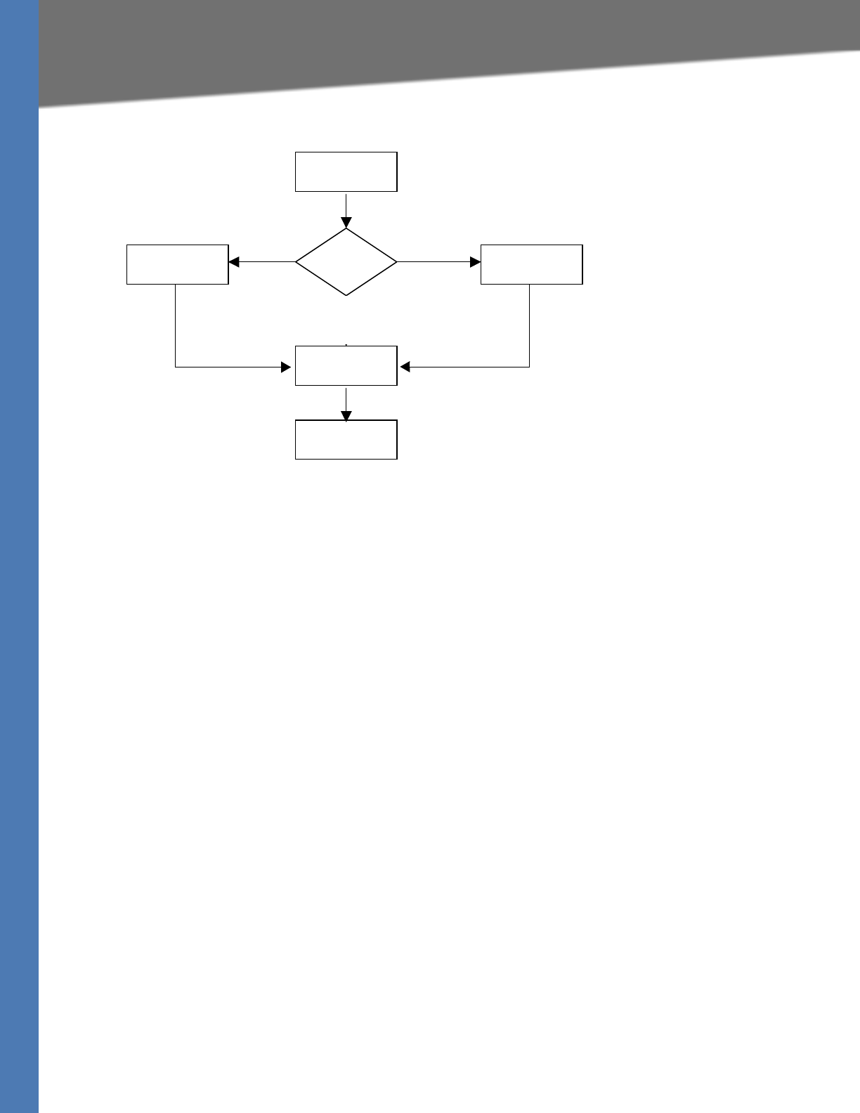
Linksys Voice System Administration Guide 147
Remote Provisioning Features
Figure A-5 Unprovisioned Client Station Acquiring a Configuration Profile
To add a new IP phone to the SPA9000, connect the IP phone to the QoS switch to which the
SPA9000 is connected and power on the unit.
To add a previously-used IP phone to the SPA9000, perform the following steps:
1. Upgrade the IP phone with SPA9000-compatible firmware.
2. Factory reset the unit.
3. Power cycle the unit.
4. Connect the unit to the switch.
The SPA9000 provisions only the necessary parameters to the client stations. It assumes the rest
of the parameters have appropriate values, which are either the default values or manually
configured values. For example, the SPA9000 provisions only Extension 1 on the client stations.
Access the administration web server using the Administrator account to manually configure
other extensions on specific client stations.
Manual Client Configuration
The client stations can also be manually configured with the contents of the profile served by
the SPA9000.
The following XML file is served by the SPA9000 when a client station requests /spa$PSN.cfg
<flat-profile>
<Resync_Periodic>1</Resync_Periodic>
<Profile_Rule>tftp://spa-9000-ip-address:69/cfg/init_$MA.xml</Profile_Rule>
</flat-profile>
The following XML file is served by the SPA9000 when client station requests /cfg/init_$MA.xml:
<flat-profile>
<User_ID_1_>next-available-user-id</User_ID_1_>
<Extension_1_>1</Extension_1_>
DHCP
Option 66? Look For
Config Server
Request
/spa$PSN.cfg
Request
/cfg/init_$MA.xml
Request
/cfg/generic.xml
NoYes

Linksys Voice System Administration Guide 148
Remote Provisioning Features
<Short_Name_1_>next-available-user-id</Short_Name_1>
<Extension_2_>1</Extension_2_>
<Short_Name_2_>next-available-user-id</Short_Name_2>
<Extension_3_>1</Extension_3_>
<Short_Name_3_>next-available-user-id</Short_Name_3>
<Extension_4_>1</Extension_4_>
<Short_Name_4_>next-available-user-id</Short_Name_4>
<Station_Name>client-station-mac-address</Station Name>
<Resync_Periodic>1</Resync_Periodic>
<Resync_Error_Retry_Delay>10</Resync_Error_Retry_Delay>
<Profile_Rule>tftp://spa-9000-ip-address:69/cfg/generic.xml</Profile_Rule>
<Linksys_Key_System>1</Linksys_Key_System>
</flat-profile>
The following XML file is served by the SPA9000 when a client station requests /cfg/generic.xml:
<flat-profile>
<Resync_Periodic>0</Resync_Periodic>
<Resync_Error_Retry_Delay>3600</Resync_Error_Retry_Delay>
<Admin_Passwd>spa-9000-admin-passwd</Admin_Passwd>
<Password_1_>phone-ext-password</Password_1_>
<Proxy_1_>spa-9000-ip-address:proxy-listen-port</Proxy_1_>
<Voice_Mail_Server_1_>spa-9000-ip-address:proxy-listen-port </Voice_Mail_Server_1_>
<Voice_Mail_Number>vmm</Voice_Mail_Number>
<Cfwd_Busy_Dest>vm</Cfwd_Busy_Dest>
<Cfwd_No_Ans_Dest>vm</Cfwd_No_Ans_Dest>
<Multicast_Address>spa-9000-multicast-address</Multicast_Address>
<Upgrade_Rule>phone-upgrade-rule</Upgrade_Rule>
<Dial_Plan>phone-dial-plan</Dial_Plan>
<Linksys_Key_System>1</Linksys_Key_System>
<Remote_Party_ID_1_>1</Remote_Party_ID_1_>
<Time_Zone>time-zone</Time_Zone>
<Daylight_Saving_Time_Rule>daylight-saving-time</Daylight_Saving_Time_Rule>
</flat-profile>
Table A-2 lists the variables used in these XML files.
Table A-2 Variables Used in XML Configuration Files
Variable Description
spa-9000-ip-address IP address of the SPA9000 SIP Proxy.
proxy-listen-port Port at which the SPA9000 SIP Proxy is listening. This value is
configured in <Proxy Listen Port>.
client-station-mac-address This is the MAC address of the client station who is
requesting the profile /cfg/init_$MA.xml (in other words, the
$MA portion of the requested filename).
next-available-user-id The current value of <Next Auto User ID>.
Phone-upgrade-rule Upgrade rule to be used by the client stations. This value is
configured in <Phone Upgrade Rule>.
Phone-dial-plan Dial plan to be used by the client stations. This value is
configured in <Phone Dial Plan>.
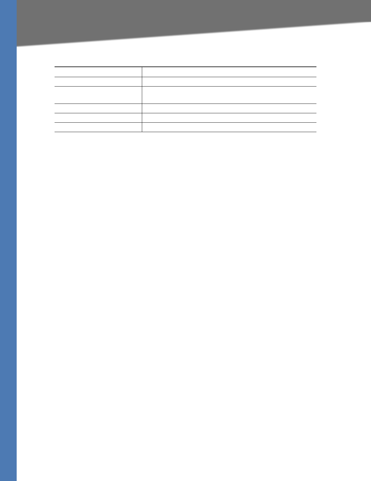
Linksys Voice System Administration Guide 149
Remote Provisioning Features
Client stations download spa$PSN.cfg and init_$MA.xml only once for initial configuration.
However, they download generic.xml on every reboot. Therefore, parameters manually
configured on the client station that overlap with the contents of generic.xml are overwritten
with the SPA9000-supplied values. The list of parameters included in generic.xml are thus
purposely kept to a very small set.
Client Registration
All client stations served by the SPA9000 must register to the SPA9000, which does not allow a
station to make calls unless it is registered. If the client station is configured with Station Name,
it should include a P-STATION-NAME header in the REGISTER request. Following is an example
where User-A has been assigned a primary extension of 5031.
REGISTER sip:192.168.0.1:6060 SIP/2.0
Via: SIP/2.0/UDP 192.168.0.4:5060;branch=z9hG4bK-8865c41e
From: “User-A” <sip:5031@192.168.0.1:6060>;tag=a76a3e1dfc6045cdo0
To: “User-A” <sip:5031@192.168.0.1:6060>
Call-ID: 52dab65d-21d02a8d@192.168.0.4
CSeq: 1 REGISTER
Max-Forwards: 70
Contact: “User-A” <sip:5031@192.168.0.4:5060>;expires=3600
User-Agent: Sipura/SPA841-3.1.4(a0714sec)
P-Station-Name: User-A
Content-Length: 0
Allow: ACK, BYE, CANCEL, INFO, INVITE, NOTIFY, OPTIONS, REFER, SUBSCRIBE
Allow-Events: dialog
In this example, User-A shares a line appearance with User-B, whose primary extension is 5041.
Extension 2 on the User-A station must then be set up the same way as Extension 1 (User-A
primary extension), but with the <Shared User ID> parameter set to 5041. The User-A station
then performs a third-party registration for Extension 2, as shown below. Note that the TO
header <user-id> parameter is the User-B primary extension.
REGISTER sip:192.168.0.1:6060 SIP/2.0
Via: SIP/2.0/UDP 192.168.0.4:5061;branch=z9hG4bK-25c8108c
From: “User-A” <sip:5031@192.168.0.1:6060>;tag=3c43d094a9424bo1
To: “User-A” <sip:5041@192.168.0.1:6060>
Call-ID: 26c913d8-485f71e3@192.168.0.4
CSeq: 1 REGISTER
Max-Forwards: 70
Contact: “User-A” <sip:5041@192.168.0.4:5061>;expires=3600
User-Agent: Sipura/SPA841-3.1.4(a0714sec)
time-zone <Time Zone> value that is configured on the SPA9000.
daylight-saving-time <Daylight Saving Time Rule> value that is configured on the
SPA9000.
phone-ext-password <Phone Ext Password> value configured on the SPA9000.
spa-9000-admin-passwd <Admin Passwd> value configured on the SPA9000.
spa-9000-multicast-address <Multicast Address> value configured on the SPA9000.
Table A-2 Variables Used in XML Configuration Files
Variable Description

Linksys Voice System Administration Guide 150
Remote Provisioning Features
P-Station-Name: 000e08daf417
Content-Length: 0
Allow: ACK, BYE, CANCEL, INFO, INVITE, NOTIFY, OPTIONS, REFER, SUBSCRIBE
Allow-Events: dialog
The 200 reply sent by the SPA9000 to the client station REGISTER request includes a DATE
header that the client station can use to synchronize with its local real-time clock. The time
served in the DATE header is the local time (as opposed to GMT). There is thus no need to
configure an NTP server or a time zone on the client stations. This assumes that the SPA9000
can maintain the real-time clock based on an NTP server or a DATE header supplied by the ITSP.
Following is an example of a 200 response to REGISTER (note that there is no weekday in the
DATE header):
SIP/2.0 200 OK
To: “User-A” <sip:5031@192.168.0.1:6060>;tag=41a7-0
From: “User-A” <sip:5031@192.168.0.1:6060>;tag=8d0bd416dc8a7ec2o0
Call-ID: 9a12cb26-8d9172f2@192.168.0.4
CSeq: 1 REGISTER
Via: SIP/2.0/UDP 192.168.0.4:5060;branch=z9hG4bK-e62fe987
Contact: sip:5031@192.168.0.4:5060;expires=3600
Content-Length: 0
Date: Mon, 18 Jul 2005 14:39:40 PST
Using the Upgrade URL
Remote firmware upgrade is achieved via TFTP or HTTP (firmware upgrades using HTTPS are
not supported). Remote upgrades are controlled by configuring the desired firmware image
URL into the SPA9000 via a remote profile resync.
Note To use this feature, the Upgrade Enable field on the Voice > Provisioning
page must be set to Yes.
SYNTAX:
http://spa-ip-addr/admin/upgrade?[protocol://][server-name[:port]][/firmware-pathname]
EXAMPLE: http://192.168.2.217/admin/upgrade?tftp://192.168.2.251/spaconf.cfg
Both HTTP and TFTP are supported for the upgrade operation.
• If no protocol is specified, TFTP is assumed. If no server-name is specified, the host that
requests the URL is used as server-name.
• If no port specified, the default port of the protocol is used. (69 for TFTP or 80 for HTTP)
•The firmware-pathname is typically the file name of the binary located in a directory on
the TFTP or HTTP server. If no firmware-pathname is specified, /spa.bin is assumed, as in
the following example: http://192.168.2.217/admin/upgrade?tftp://192.168.2.251/spa.bin

Linksys Voice System Administration Guide 151
Remote Provisioning Features
Using the Resync URL
The SPA9000 can be configured to automatically resynchronize its internal configuration state
to a remote profile periodically and on power up. The automatic resyncs are controlled by
configuring the desired profile URL into the device.
Note The SPA resynchronizes only when it is idle.
SYNTAX:
http://spa-ip-addr/admin/resync?[[protocol://][server-name[:port]]/profile-pathname]
EXAMPLE: http://192.168.2.217/admin/resync?tftp://192.168.2.251/spaconf.cfg
•If no parameter follows /resync?, the Profile Rule setting from the Provisioning page is
used.
• If no protocol is specified, TFTP is assumed. If no server-name is specified, the host that
requests the URL is used as server-name.
• If no port is specified, the default port is used (69 for TFTP, 80 for HTTP, and 443 for
HTTPS).
• The profile-path is the path to the new profile with which to resync.
Using the Reboot URL
You can use the Reboot URL to reboot the SPA9000.
Note The SPA9000 reboots only when it is idle.
SYNTAX: http://spa-ip-addr/admin/reboot
EXAMPLE: http://192.168.2.217/admin/reboot

Linksys Voice System Administration Guide 152
BRouter Tab
SPA9000 Field Reference
This appendix describes the fields on each page of the SPA9000 administration web server.
After you connect to the SPA9000, you can use the following tabs to open the modules of the
application:
•”Router Tab,” on page 152
•”Voice tab,” on page 156
Router Tab
After you click the Router tab, you can choose the following pages:
•”Status page,” on page 152
•”Wan Setup page,” on page 153
•”Lan Setup page and Application page,” on page 156
Router tab >
Status page
You can use the Status page to view information about the SPA9000. The Status page has the
following sections:
•”Product Information section,” on page 152
•”System Status section,” on page 153
Router tab > Status page >
Product Information section
Product Name Model number of the SPA9000
Serial Number Serial number of the SPA9000
Software Version Version number of the SPA9000 software
Hardware Version Version number of the SPA9000 hardware
MAC Address MAC address of the SPA9000
Client Certificate Status of the client certificate, which authenticates the SPA9000 for use
in the ITSP network
Customization For an remote configuration (RC) unit, this field indicates whether the
unit has been customized or not. Pending indicates a new RC unit that is
ready for provisioning. If the unit has already retrieved its customized
profile, this field displays the name of the company that provisioned the
unit.

Linksys Voice System Administration Guide 153
Router Tab
Router tab > Status page >
System Status section
Router tab >
Wan Setup page
You can use the Wan Setup page to enter the WAN connection settings. This page includes the
following sections:
•”Internet Connection Settings section,” on page 154
•”Static IP Settings section,” on page 154
•”PPPoE Settings section,” on page 154
•”Optional Settings section,” on page 154
•”MAC Clone Settings section,” on page 155
•”Remote Management section,” on page 155
•”QOS Settings section,” on page 155
Licenses When populated with the value K0, indicates that the SPA9000 is
licensed for up to 16 users; if this field is blank, install firmware version
5.2.5 or higher.
Current Time Current date and time of the system; for example, 10/3/2003 16:43:00
Elapsed Time Total time elapsed since the last reboot of the system; for example, 25
days and 18:12:36
Wan Connection Type The connection type: DHCP or Static IP
Current IP The current IP address assigned to the SPA9000
Host Name The current host name assigned to the SPA9000
Domain The network domain name of the SPA9000
Current Netmask The network mask assigned to the SPA9000
Current Gateway The default router assigned to the SPA9000
Primary DNS The primary DNS server assigned to the SPA9000
Secondary DNS The secondary DNS server assigned to the SPA9000
LAN IP Address The LAN IP address of the SPA9000. SPA9000
NOTE: Do not deploy the SPA9000 as a router.
Broadcast Pkts Sent Total number of broadcast packets sent
Broadcast Bytes Sent Total number of broadcast bytes sent
Broadcast Pkts Recv Total number of broadcast bytes received
Broadcast Bytes Recv Total number of broadcast bytes received and processed
Broadcast Pkts Dropped Total number of broadcast packets received but not processed
Broadcast Bytes Dropped Total number of broadcast bytes received but not processed
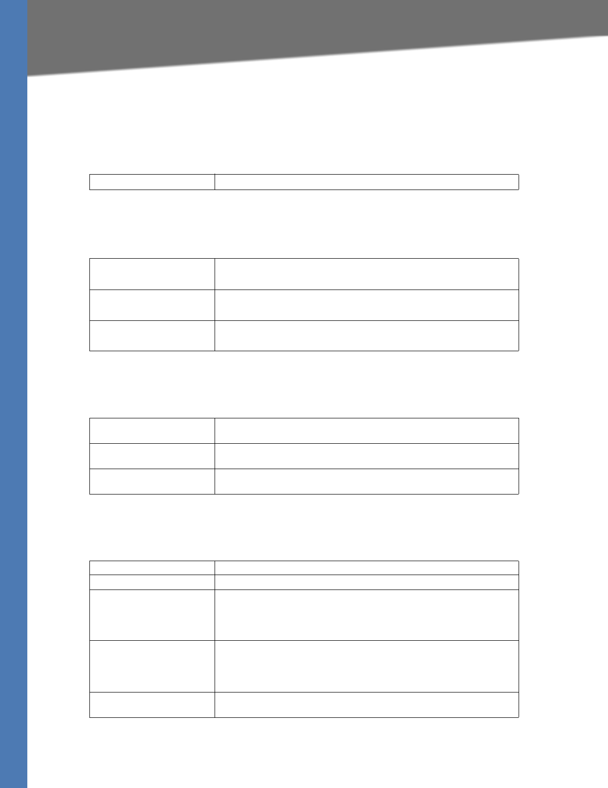
Linksys Voice System Administration Guide 154
Router Tab
•”VLAN Settings section,” on page 155
Router tab > Wan Setup page >
Internet Connection Settings section
Router tab > Wan Setup page >
Static IP Settings section
Router tab > Wan Setup page >
PPPoE Settings section
Router tab > Wan Setup page >
Optional Settings section
Connection Type IP address assignment scheme, static or DHCP.
Static IP Static IP address of SPA9000, which takes effect if DHCP is disabled.
Default: 0.0.0.0
NetMask The NetMask used by SPA9000 when DHCP is disabled.
Default: 255.255.255.0
Gateway The default gateway used by SPA9000 when DHCP is disabled.
Default: 0.0.0.0
PPPoE Login Name The account name assigned by the ISP for connecting on a Point-to-
Point Protocol over Ethernet (PPPoE) link.
PPPoE Login Password The password assigned by the ISP for connecting on a Point-to-Point
Protocol over Ethernet (PPPoE) link.
PPPoE Service Name The service name assigned by the ISP for connecting on a Point-to-Point
Protocol over Ethernet (PPPoE) link.
HostName The host name of the SPA9000
Domain The network domain of the SPA9000.
Primary DNS The DNS server that is used by the SPA9000
NOTE: When DHCP is enabled, you can enter the IP address of a DNS
server in addition to DHCP-supplied DNS servers. When DHCP is
disabled, enter the primary DNS server. Default: 0.0.0.0
Secondary DNS The DNS server that is used by the SPA9000
NOTE: When DHCP is enabled, you can enter the IP address of a DNS
server in addition to DHCP-supplied DNS servers. When DHCP is
disabled, enter the primary DNS server. Default: 0.0.0.0
DNS Server Order The method for selecting the DNS server: Manual, Manual/DHCP, and
DHCP/Manual

Linksys Voice System Administration Guide 155
Router Tab
Router tab > Wan Setup page >
MAC Clone Settings section
Router tab > Wan Setup page >
Remote Management section
Router tab > Wan Setup page >
QOS Settings section
Router tab > Wan Setup page >
VLAN Settings section
DNS Query Mode The mode of DNS query: parallel or sequential
NOTE: With parallel DNS query mode, the SPA9000 sends the same DNS
lookup request to all the DNS servers at the same time, and the first
incoming reply is accepted by the SPA9000.
Default: parallel
Primary NTP Server The IP address or name of the primary NTP server
Secondary NTP Server The IP address or name of the secondary NTP server
DHCP IP Revalidate Timer:
Enable MAC Clone Service Enable if you need to assign a different MAC address to the SPA9000 via
the Cloned MAC Address field.
Cloned MAC Address The MAC address that you need the SPA9000 to assume
Enable WAN Web Server Allows (yes) or prevents (no) access to the administration web server
from a computer that is not directly connected to the SPA9000.
Default: yes
WAN Web Server Port The port that is used for WAN access to the SPA9000
Default: 80
QoS Policy The queueing discipline, set to none or token bucket filter (TBF). TBF
limits the rate of transmission to not attempt to exceed the Maximum
Uplink Speed.
QOS QDisc Allow QoS Queuing. Options are None or TBF (token bucket filter).
Information can be found at about TBF at: http://lartc.org/howto/
lartc.qdisc.classless.html
Maximum Uplink Speed Define this value to allow the token bucket filter queueing discipline to
manage traffic flow to ensure high quality voice audio.
Enable VLAN Enable voice data to be tagged with the defined VLAN ID.
NOTE: Choose yes If your SPA9000 is connected to a switch that uses
VLAN tagging.

Linksys Voice System Administration Guide 156
Voice tab
Router tab >
Lan Setup page and Application page
Note Linksys Engineering and Quality Assurance strongly advise against
using the SPA9000 as a router. For this reason, the Lan Setup and
Application tabs should not be modified from the default, unused state.
The SPA9000 must only be connected to a switch via the SPA9000
INTERNET RJ45 connector. Do not connect any cable to the SPA9000
ETHERNET port, or you may experience degraded audio performance.
Voice tab
After you click the Voice tab, you can use the following pages:
•”Info page,” on page 156
•”Voice tab >,” on page 159
•”SIP Page,” on page 160
•”Regional page,” on page 176
•”FXS 1/2 page,” on page 189
•”Line 1/2/3/4 page,” on page 196
Voice tab >
Info page
You can use the Info page to view information about the FXS devices and the line interfaces.
This page includes the following sections:
•”Product Information section,” on page 152
•”System Status section,” on page 157
•”FXS 1/2 Status section,” on page 157
•”Line 1/2/3/4 Status section,” on page 158
•”Auto Attendant Prompt Status section,” on page 158
•”Internal Music Status section,” on page 159
VLAN ID The VLAN tag for the VLAN to which the SPA9000 is assigned
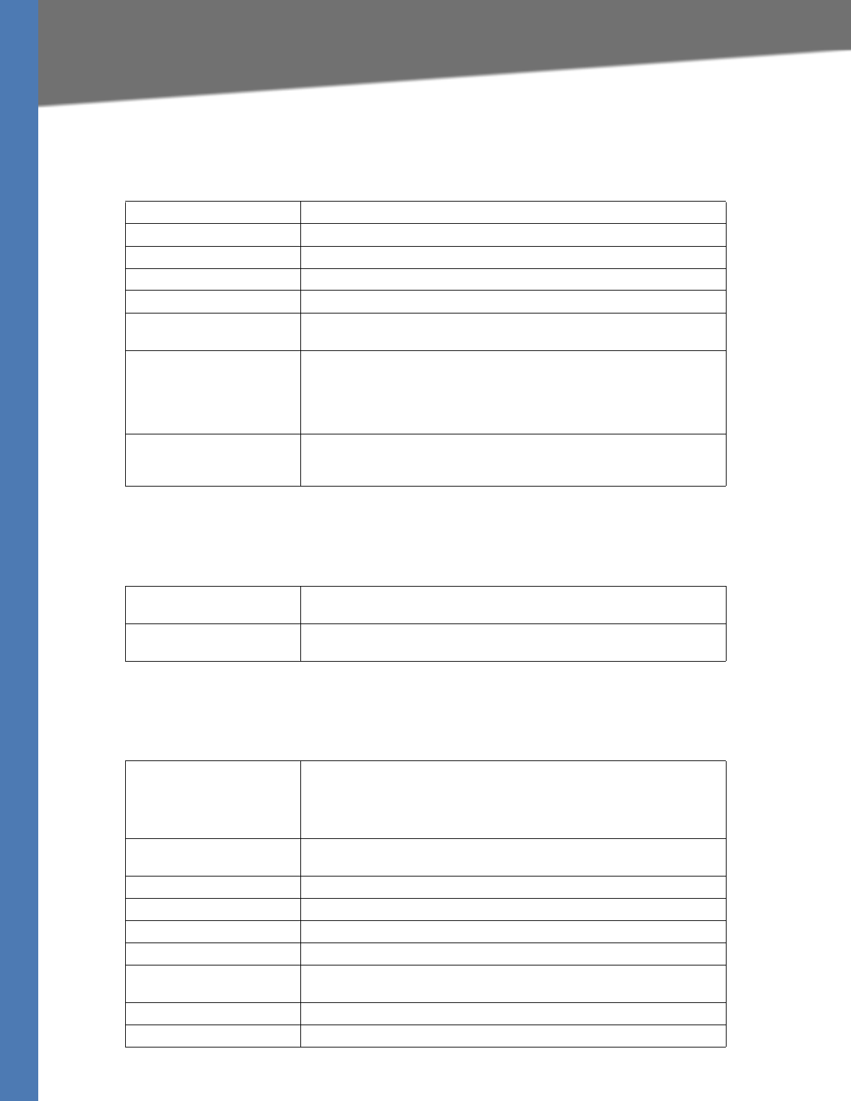
Linksys Voice System Administration Guide 157
Voice tab
Voice tab > Info page >
Product Information section
Voice tab > Info page >
System Status section
Voice tab > Info page >
FXS 1/2 Status section
Product Name The model number of the SPA9000
Serial Number The serial number of the SPA9000
Software Version The version number of the SPA9000 software
Hardware Version The version number of the SPA9000 hardware
MAC Address The MAC address of the SPA9000
Client Certificate The status of the client certificate, which authenticates the SPA9000 for
use in the ITSP network
Customization For an remote configuration (RC) unit, this field indicates whether the
unit has been customized or not. Pending indicates a new RC unit that is
ready for provisioning. If the unit has already retrieved its customized
profile, this field displays the name of the company that provisioned the
unit.
Licenses When populated with the value K0, indicates that the SPA9000 is
licensed for up to 16 users; if this field is blank, install firmware version
5.2.5 or higher.
Current Time The current date and time of the system; for example, 10/3/2003
16:43:00
Elapsed Time The total time elapsed since the last reboot of the system; for example,
25 days and 18:12:36
Hook State The readiness of the device that is connected to the corresponding
Phone port on the SPA9000
•On: Ready for use
•Off: In use
Message Waiting Indicates whether the station assigned to the FXS port has new
voicemail waiting: Yes or No
Call Back Active Indicates whether a call back request is in progress: Yes or No
Last Called Number Last number called
Last Caller Number Number of the last caller if available from caller ID, example 4085551212
Call 1/2 State Status of the call:, Ringing, Idle, or Connected
Call 1/2 Tone Type of tone used by the call, for example Ring Back 2 for inbound call or
None for outbound call
Call 1/2 Encoder Codec used for encoding
Call 1/2 Decoder Codec used for decoding

Linksys Voice System Administration Guide 158
Voice tab
Voice tab > Info page >
Line 1/2/3/4 Status section
)
Voice tab > Info page >
Auto Attendant Prompt Status section
Call 1/2 FAX Status of the fax pass-through mode; set to No if this line is used for
voice calls
Call 1/2 Type Direction of the call: Inbound or Outbound
Call 1/2 Remote Hold Indicates whether or not the far end has placed the call on hold: Yes or
No
Call 1/2 Callback Indicates whether the call was triggered by a call back request
Call 1/2 Peer Name Name of the peer, internal station name if local phone, or name acquired
from caller-ID
Call 1/2 Peer Phone Phone number of the other phone involved in the call, either the
extension if a local phone, or the number acquired from caller-ID
Call 1/2 Duration Duration of the call
Call 1/2 Packets Sent Number of packets sent
Call 1/2 Packets Recv Number of packets received
Call 1/2 Bytes Sent Number of bytes sent
Call 1/2 Bytes Recv Number of bytes received
Call 1/2 Decode Latency Number of milliseconds for decoder latency
Call 1/2 Jitter Number of milliseconds for receiver jitter
Call 1/2 Round Trip Delay Number of milliseconds for delay
Call 1/2 Packets Lost Number of packets lost
Call 1/2 Packet Error Number of invalid packets received
Registration State The status of the registration on the line interface: Registered or Not
Registered
Last Registration At Last date and time the line was registered: mm/dd/yyyy hh:mm:ss
Next Registration In Number of seconds before the next registration renewal; example 2672s
Message Waiting Indicates whether you have new voicemail waiting: Yes or No
Mapped SIP Port number of the SIP port mapped by NAT
Field Description
Prompt 1 The duration of the prompt in milliseconds
Prompt 2 The duration of the prompt in milliseconds
Prompt 3 The duration of the prompt in milliseconds
Prompt 4 The duration of the prompt in milliseconds
Prompt 5 The duration of the prompt in milliseconds
Prompt 6 The duration of the prompt in milliseconds
Prompt 7 The duration of the prompt in milliseconds
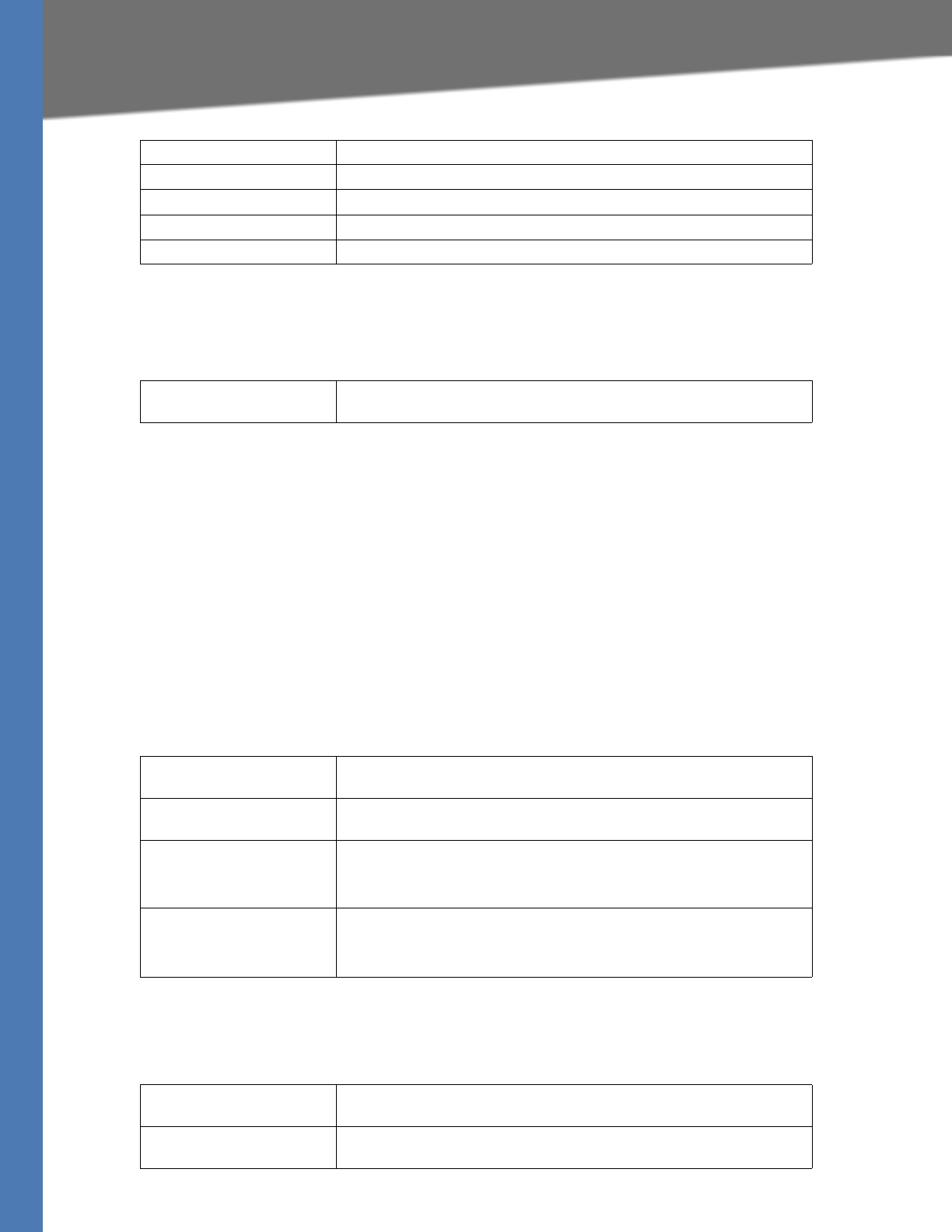
Linksys Voice System Administration Guide 159
Voice tab
Voice tab > Info page >
Internal Music Status section
Voice tab >
System page
You can use the System page to set up restricted access domains, manage web access to the
sPA9000, set the logon passwords, and manage system log settings and debugging. This page
includes the following sections:
•”System Configuration section,” on page 159
•”Miscellaneous Settings section,” on page 159
Voice tab > System page >
System Configuration section
Voice tab > System page >
Miscellaneous Settings section
Prompt 8 The duration of the prompt in milliseconds
Prompt 9 The duration of the prompt in milliseconds
Prompt 10 The duration of the prompt in milliseconds
Space Remaining Number of milliseconds available
Current AA Auto-attendant in use; example: Daytime
Installed Music Path The pathname for the music source used for the music-on-hold feature;
example: Factory Default
Restricted Access Domains Define up to five IP addresses or fully qualified domain names to identify
the domains in which the SPA9000 is allowed to operate.
Enable Web Admin Access Allows (yes) or prevents (no) local access to the administration web
server
Admin Passwd Password for the administrator. Up to 39 characters are allowed for
the passwords. All characters are legal.
Default: no password
User Password Password for the user. Up to 39 characters are allowed for the
passwords. All characters are legal.
Default: no password
Syslog Server The IP address of the syslog server to which the SPA9000 sends syslog
messages. Leave blank if you do not want to receive syslog messages.
Debug Server The IP address of the debug server, which logs debug information. The
level of detailed output depends on the Debug Level parameter setting.

Linksys Voice System Administration Guide 160
Voice tab
Voice tab >
SIP Page
You can use the SIP page to enter many settings that are important for the proper functioning
of SIP on your SPA9000. This page includes the following sections:
•”SIP Parameters section,” on page 160
•”SIP Timer Values (sec) section,” on page 161
•”Response Status Code Handling section,” on page 163
•”RTP Parameters section,” on page 163
•”SDP Payload Types section,” on page 165
•”NAT Support Parameters section,” on page 166
•”PBX Parameters section,” on page 167
•”Internal Music Source Parameters section,” on page 170
•”Auto Attendant Parameters section,” on page 171
•”PBX Phone Parameters section,” on page 174
Voice tab > SIP page
SIP Parameters section
Debug Level The level of debug information that is generated, from 0 to 3. 0 is a
minimal level of debugging information that is acceptable for most
purposes. Levels 1 to 3 are typically used only by Linksys
personnel.
NOTE: Default: 0
Max Forward SIP Max Forward value, which can range from 1 to 255.
Default: 70
Max Redirection Number of times an invite can be redirected to avoid an infinite loop.
Default: 5
Max Auth Maximum number of times (from 0 to 255) a request may be challenged.
Default: 2
SIP User Agent Name User-Agent header used in outbound requests. If empty, the header is
not included. Macro expansion of $A to $D corresponding to GPP_A to
GPP_D allowed.
Default: $VERSION
SIP Server Name Server header used in responses to inbound responses.
Default: $VERSION

Linksys Voice System Administration Guide 161
Voice tab
Voice tab > SIP page
SIP Timer Values (sec) section
SIP Reg User Agent Name User-Agent name to be used in a REGISTER request. If this value is not
specified, the <SIP User Agent Name> is also used for the REGISTER
request.
Default: blank
SIP Accept Language Accept-Language header used. There is no default (this indicates
SPA9000 does not include this header). If empty, the header is not
included.
DTMF Relay MIME Type MIME Type used in a SIP INFO message to signal a DTMF event.
Default: application/dtmf-relay
Hook Flash MIME Type MIME Type used in a SIP INFO message to signal a hook flash event.
Default: application/hook-flash
Remove Last Reg Lets you remove the last registration before registering a new one if the
value is different. Select yes or no from the drop-down menu.
Default: no
Use Compact Header Lets you use compact SIP headers in outbound SIP messages. Select yes
or no from the drop-down menu. If set to yes, the SPA9000 uses
compact SIP headers in outbound SIP messages. If set to no, the
SPA9000 uses normal SIP headers. If inbound SIP requests contain
compact headers, SPA9000 reuses the same compact headers when
generating the response regardless the settings of the <Use Compact
Header> parameter. If inbound SIP requests contain normal headers,
SPA9000 substitutes those headers with compact headers (if defined by
RFC 261) if <Use Compact Header> parameter is set to yes.
Default: no
Escape Display Name Select yes if you want the SPA9000 to enclose the string (configured in
the Display Name) in a pair of double quotes for outbound SIP
messages. Any occurrences of or \ in the string is escaped with \ and \\
inside the pair of double quotes. Otherwise, select no.
Default: no
RFC 2543 Call Hold If set to yes, unit will include c=0.0.0.0 syntax in SDP when sending a SIP
re-INVITE to the peer to hold the call. If set to no, unit will not include the
c=0.0.0.0 syntax in the SDP. The unit will always include a=sendonly
syntax in the SDP in either case.
Default: yes
Mark All AVT Packets If set to yes, all AVT tone packets (encoded for redundancy) have the
marker bit set. If set to no, only the first packet has the marker bit set for
each DTMF event.
Default: yes
SIP TCP Port Min The lowest TCP port number that can be used for SIP sessions.
Default: 5060
SIP TCP Port Max The highest TCP port number that can be used for SIP sessions.
Default: 5080
SIP T1 RFC 3261 T1 value (RTT estimate), which can range from 0 to 64 seconds.
Default: .5

Linksys Voice System Administration Guide 162
Voice tab
SIP T2 RFC 3261 T2 value (maximum retransmit interval for non-INVITE
requests and INVITE responses), which can range from 0 to 64 seconds.
Default: 4
SIP T4 RFC 3261 T4 value (maximum duration a message remains in the
network), which can range from 0 to 64 seconds.
Default: 5
SIP Timer B RFC 3261 INVITE transaction time-out value, which can range from 0 to
64 seconds.
Default: 32
SIP Timer F RFC 3261 Non-INVITE transaction time-out value, which can range from
0 to 64 seconds.
Default: 32
SIP Timer H RFC 3261 time-out value for ACK receipt, which can range from 0 to 64
seconds.
Default: 32
SIP Timer D RFC 3261 wait time for response retransmits, which can range from 0 to
64 seconds.
Default: 32
SIP Timer J RFC 3261 wait time for Non-INVITE response hang-around time, which
can range from 0 to 64 seconds.
Default: 32
INVITE Expires INVITE request Expires header value. If you enter 0, the Expires header is
not included in the request. Range: 0–(231–1).
Default: 240
ReINVITE Expires ReINVITE request Expires header value. If you enter 0, the Expires header
is not included in the request. Range: 0–(231–1).
Default: 30
Reg Min Expires Minimum registration expiration time allowed from the proxy in the
Expires header or as a Contact header parameter. If the proxy returns a
value less than this setting, the minimum value is used.
Default: 1
Reg Max Expires Maximum registration expiration time allowed from the proxy in the
Min-Expires header. If the value is larger than this setting, the maximum
value is used.
Default: 7200
Reg Retry Intvl Interval to wait before the SPA9000 retries registration after failing
during the last registration.
Default: 30
Reg Retry Long Intvl When registration fails with a SIP response code that does not
match<Retry Reg RSC>, the SPA9000 waits for the specified length of
time before retrying. If this interval is 0, the SPA9000 stops trying. This
value should be much larger than the Reg Retry Intvl value, which
should not be 0.
Default: 1200
Reg Retry Random Delay Random delay range (in seconds) to add to <Register Retry Intvl> when
retrying REGISTER after a failure.
Default: 0 (disabled)
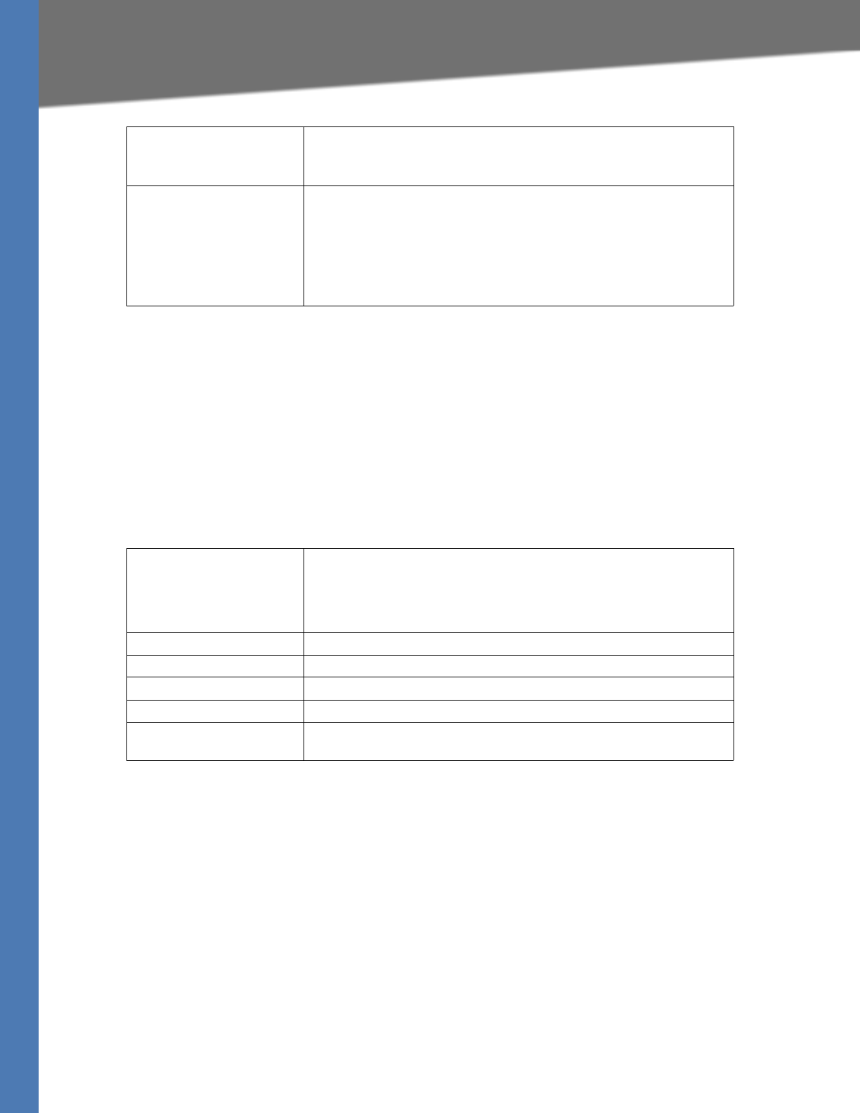
Linksys Voice System Administration Guide 163
Voice tab
Voice tab > SIP page
Response Status Code Handling section
The RSC handling defines the behavior of the user audio tones played under specific conditions
signaled by the network, such as congestion, queuing, etc. The default settings (blank) are
adequate is most circumstances.
NOTE: These settings need to be compatible with the ITSP network settings. The ITSP you use
will inform you about any specific setting you need to modify on these areas. These parameters
have impact on the signaling and audio reliability.
Voice tab > SIP page
RTP Parameters section
The RTP parameters define the specification of the RTP audio packets. The most important
parameter is the RTP Packet size (time) which defines the interval of transmission of the RTP
packets. It is extremely important that time interval matches the ITSP settings. Its default value
is 0.030 (30 milliseconds).
NOTE: These settings need to be compatible with the ITSP network settings. The ITSP you use
will inform you about any specific setting you need to modify on these areas. These parameters
have impact on the signaling and audio reliability.
Reg Retry Long Random
Delay
Random delay range (in seconds) to add to <Register Retry Long Intvl>
when retrying REGSITER after a failure.
Default: 0 (disabled)
Reg Retry Intvl Cap The maximum value to cap the exponential back-off retry delay (which
starts at <Register Retry Intvl> and doubles on every REGISTER retry
after a failure). In other words, the retry interval is always at <Register
Retry Intvl> seconds after a failure. If this feature is enabled, <Reg Retry
Random Delay> is added on top of the exponential back-off adjusted
delay value.
Default: 0 (disables the exponential back-off feature)
SIT1 RSC SIP response status code for the appropriate Special Information Tone
(SIT). For example, if you set the SIT1 RSC to 404, when the user makes a
call and a failure code of 404 is returned, the SIT1 tone is played. Reorder
or Busy Tone is played by default for all unsuccessful response status
code for SIT 1 RSC through SIT 4 RSC.
SIT2 RSC SIP response status code to INVITE on which to play the SIT2 Tone.
SIT3 RSC SIP response status code to INVITE on which to play the SIT3 Tone.
SIT4 RSC SIP response status code to INVITE on which to play the SIT4 Tone.
Try Backup RSC SIP response code that retries a backup server for the current request.
Retry Reg RSC Interval to wait before the SPA9000 retries registration after failing
during the last registration.

Linksys Voice System Administration Guide 164
Voice tab
RTP Port Min Minimum port number for RTP transmission and reception. <RTP Port
Min> and <RTP Port Max> should define a range that contains at least 4
even number ports, such as 100 – 106.
Default: 16384
RTP Port Max Maximum port number for RTP transmission and reception.
Default: 16482
RTP Packet Size Packet size in seconds, which can range from 0.01 to 0.16. Valid values
must be a multiple of 0.01 seconds.
Default: 0.030
Max RTP ICMP Err Number of successive ICMP errors allowed when transmitting RTP
packets to the peer before the SPA9000 terminates the call. If value is set
to 0, the SPA9000 ignores the limit on ICMP errors.
Default: 0
RTCP Tx Interval Interval for sending out RTCP sender reports on an active connection. It
can range from 0 to 255 seconds. During an active connection, the
SPA9000 can be programmed to send out compound RTCP packet on
the connection. Each compound RTP packet except the last one
contains a SR (Sender Report) and a SDES.(Source Description). The last
RTCP packet contains an additional BYE packet. Each SR except the last
one contains exactly 1 RR (Receiver Report); the last SR carries no RR. The
SDES contains CNAME, NAME, and TOOL identifiers. The CNAME is set to
<User ID>@<Proxy>, NAME is set to <Display Name> (or Anonymous if
user blocks caller ID), and TOOL is set to the Vendor/Hardware-platform-
software-version (such as Linksys/SPA9000-1.0.31(b)). The NTP
timestamp used in the SR is a snapshot of the SPA9000’s local time, not
the time reported by an NTP server. If the SPA9000 receives a RR from
the peer, it attempts to compute the round trip delay and show it as the
<Call Round Trip Delay> value (ms) in the Info section of SPA9000 web
page.
Default: 0
No UDP Checksum Select yes if you want the SPA9000 to calculate the UDP header
checksum for SIP messages. Otherwise, select no.
Default: no
Stats In BYE Determines whether the SPA9000 includes the P-RTP-Stat header or
response to a BYE message. The header contains the RTP statistics of the
current call. Select yes or no from the drop-down menu. The format of
the P-RTP-Stat header is:
P-RTP-State: PS=<packets sent>,OS=<octets sent>,PR=<packets
received>,OR=<octets received>,PL=<packets lost>,JI=<jitter in
ms>,LA=<delay in ms>,DU=<call duration in
s>,EN=<encoder>,DE=<decoder>.
Default: no

Linksys Voice System Administration Guide 165
Voice tab
Voice tab > SIP page
SDP Payload Types section
The SDP Payload types defines the naming/numbering conventions for the audio codecs used
by the SPA9000 when communicating with the ITSP network. Naming should match the ITSP
names used. The default values are adequate in most circumstances.
NOTE: These settings need to be compatible with the ITSP network settings. The ITSP you use
will inform you about any specific setting you need to modify on these areas. These parameters
have impact on the signaling and audio reliability.
•Dynamic Payloads: The configured dynamic payloads are used for outbound calls only
where the SPA9000 presents the SDP offer. For inbound calls with a SDP offer, the
SPA9000 follows the caller dynamic payload type assignments.
•Codec Names: The SPA9000 uses the configured codec names in its outbound SDP. The
SPA9000 ignores the codec names in incoming SDP for standard payload types (0 – 95).
For dynamic payload types, the SPA9000 identifies the codec by the configured codec
names. Comparison is case-insensitive.
NSE Dynamic Payload NSE dynamic payload type. The valid range is 96-127.
Default: 100
AVT Dynamic Payload AVT dynamic payload type. The valid range is 96-127.
Default: 101
INFOREQ Dynamic Payload INFOREQ dynamic payload type.
Default: blank
G726r16 Dynamic Payload G.726-16 dynamic payload type. The valid range is 96-127.
Default: 98
G726r24 Dynamic Payload G.726-24 dynamic payload type. The valid range is 96-127.
Default: 97
G726r32 Dynamic Payload G726r32 dynamic payload type.
Default: 2
G726r40 Dynamic Payload G.726-40 dynamic payload type. The valid range is 96-127.
Default: 96
G729b Dynamic Payload G.729b dynamic payload type. The valid range is 96-127.
Default: 99
NSE Codec Name NSE codec name used in SDP.
Default: NSE
AVT Codec Name AVT codec name used in SDP.
Default: telephone-event
G711u Codec Name G.711u codec name used in SDP.
Default: PCMU
G711a Codec Name G.711a codec name used in SDP.
Default: PCMA

Linksys Voice System Administration Guide 166
Voice tab
Voice tab > SIP page
NAT Support Parameters section
G726r16 Codec Name G.726-16 codec name used in SDP.
Default: G.726-16
G726r24 Codec Name G.726-24 codec name used in SDP.
Default: G.726-24
G726r32 Codec Name G.726-32 codec name used in SDP.
Default: G.726-32
G726r40 Codec Name G.726-40 codec name used in SDP.
Default: G.726-40
G729a Codec Name G.729a codec name used in SDP.
Default: G.729a
G729b Codec Name G.729b codec name used in SDP.
Default: G.729ab
G723 Codec Name G.723 codec name used in SDP.
Default: G.723
EncapRTP Codec Name EncapRTP codec name used in SDP.
Default: encaprtp
Handle VIA received If you select yes, the SPA9000 processes the received parameter in the
VIA header (this value is inserted by the server in a response to any one
of its requests). If you select no, the parameter is ignored. Select yes or
no from the drop-down menu.
Default: no
Handle VIA rport If you select yes, the SPA9000 processes the rport parameter in the VIA
header (this value is inserted by the server in a response to any one of its
requests). If you select no, the parameter is ignored. Select yes or no
from the drop-down menu.
Default: no
Insert VIA received Inserts the received parameter into the VIA header of SIP responses if
the received-from IP and VIA sent-by IP values differ. Select yes or no
from the drop-down menu.
Default: no
Insert VIA rport Inserts the rport parameter into the VIA header of SIP responses if the
received-from IP and VIA sent-by IP values differ. Select yes or no from
the drop-down menu.
Default: no
Substitute VIA Addr Lets you use NAT-mapped IP-address port values in the VIA header.
Select yes or no from the drop-down menu.
Default: no
Send Resp To Src Port Sends responses to the request source port instead of the VIA sent-by
port. Select yes or no from the drop-down menu.
Default: no

Linksys Voice System Administration Guide 167
Voice tab
Voice tab > SIP page
PBX Parameters section
STUN Enable Enables the use of STUN to discover NAT mapping. Select yes or no from
the drop-down menu.
Default: no
STUN Test Enable If the STUN Enable feature is enabled and a valid STUN server is
available, the SPA9000 can perform a NAT-type discovery operation
when it powers on. It contacts the configured STUN server, and the
result of the discovery is reported in a Warning header in all subsequent
REGISTER requests. If the SPA9000 detects asymmetric NAT or
asymmetric firewall, NAT mapping is disabled.
Default: no
STUN Server IP address or fully-qualified domain name of the STUN server to contact
for NAT mapping discovery.
Default: blank
EXT IP External IP address to substitute for the actual IP address of the SPA9000
in all outgoing SIP messages. If 0.0.0.0 is specified, or the field is left
blank, no IP address substitution is performed.
NOTE: You must also configure port forwarding for SIP [5060-5063] and
RTP [16384-16482] when using the EXT IP field, or phone users may
experience one-way audio because the RTP stream will not find its way
between the two phones.
If this parameter is specified, the SPA9000 assumes this IP address when
generating SIP messages and SDP (if NAT Mapping is enabled for that
line). However, the results of STUN and VIA received parameter
processing, if available, supersede this statically configured value.
Default: blank
EXT RTP Port Min External port mapping number of the RTP Port Min. number. If this value
is not zero, the RTP port number in all outgoing SIP messages is
substituted for the corresponding port value in the external RTP port
range.
Default: blank
NAT Keep Alive Intvl Interval between NAT-mapping keep alive messages.
Default: 15
Field Description
Proxy Network Interface This setting tells the SPA9000 how the client stations are connected.
Choices: {LAN, WAN}. The SPA9000 communicates with client stations
via the selected interface only.
Default: WAN
NOTE: For optimum voice performance, Linksys Engineering and
Quality Assurance recommend that only WAN is used.
Proxy Listen Port Port at which the SPA9000 listens for client messages at the selected
network interface. The proxy also sends SIP messages from this port.
Default: 6060

Linksys Voice System Administration Guide 168
Voice tab
Multicast Address IP address (and port number) where the SPA9000 sends control
messages to all the client stations at once. This must be a multicast
address and must contain a port number.
Default: 224.168.168.168:6061.
Group Page Address IP address (and port number) where the SPA9000 tells the client stations
to send and receive group page RTP packets. This must be a multicast
address and must contain a port number.
Default: 224.168.168.168:34567.
Max Expires Sets the maximum allowed Registration expires value in seconds for
client stations. Linksys recommends using a relatively small value, such
as 60 or 120.
Default: 60
Force Media Proxy Forces external client stations to use the SPA9000 Media Proxy when
exchanging RTP traffic with external peers. Linksys recommends using a
relatively small value, such as 60 or 120.
Default: no
Proxy Debug Option Controls what SIP messages to log that are received at or sent from the
Proxy listen port. Choices are as follows: {
none—No logging.
1-line—Logs the start-line only for all messages,
1-line excl. OPT—Same as 1-line but excludes OPTIONS request/
response.
1-line excl. NTFY—Same as 1-line but excludes NOTIFY request/
response.
1-line excl. REG—Same as 1-line but excludes REGISTER request/
response.
1-line excl. OPT|NTFY|REG—Same as 1-line but excludes OPTIONS,
NOTIFY, and REGISTER request/response.
full—Logs all SIP messages in verbose mode.
full excl. OPT—Same as full but excludes OPTIONS request/response.
full excl. NTFY—Same as full but excludes NOTIFY request/response.
full excl. REG—Same as full but excludes REGISTER request/response.
full excl. OPT|NTFY|REG—Same as full but excludes OPTIONS, NOTIFY,
and REGISTER request/response.
Default: None

Linksys Voice System Administration Guide 169
Voice tab
Call Routing Rule Special dial plan that determines which line interfaces can be used for
an external outbound call request from client station based solely on
the target public number. The dial plan is in the (rule|rule|…|rule)
format where:
rule = <:Ln[,n[,n[,n]]]>pattern
n = 1, 2, 3, or 4,
pattern = any digit pattern (see <Dial Plan> on how to choose a digit
pattern).
If the target number matches the pattern of a rule, the Line indices in
the rule’s prefix are the line interfaces that can be used to make that call.
Matches are performed from left to right, so make sure the most specific
rules are placed first. For example:
Default: (<:L1,2,3,4>9xx.)
The default call routing rule specifies that any of the four line interfaces
can be used for any target number starting with 9 followed by at least 2
more numbers.
Call Park MOH Server The MOH Server to be used to handle a parked call. For example:
mohs@192.168.1.1:5082.
If this parameter is not specified, the internal parking lot is used to host
the parked call, in which case the parked caller hears the internal music
file.
Default: imusic
Call Park DLG Refresh Intvl The interval in seconds between refreshing a call park session.
Default: 0 (disables session refreshes)
Default Group Line Same as <Group 1/2/3/4 Line>, but applies to the default group.
Default: 1,2,3,4
Group 1/2/3/4 User ID Comma-separated list of User ID patterns. A client station whose User ID
matches any of the give patterns is considered to belong to that group.
If the User ID matches more than one group, the smallest group number
is assumed. If the User ID does not match any group, the client station is
considered to belong to the default group (also known as Group 0).
Each User ID pattern allows * and ? wildcards as well as %xx escaped
characters.
Default: blank (includes all client stations)
Group 1/2/3/4 Line Ordered comma-separated list of line interfaces. The SPA9000 attempts
to make external calls for group members in the order in which the lines
are listed.
Example: 1,3
When a group member places an outbound call, the SPA9000 attempts
to use Line 1 first. If Line 1 is not available, the SPA9000 attempts to use
Line 3.
By default, this field is blank, meaning that no line can be seized.
Hunt Groups Defines one or more hunt groups that can be called directly by any
client station like a regular extension. The syntax is the same as
<Contact List>. Each defined group extension and name also appears in
the corporate directory. This parameter is parsed twice by the SPA9000
such that a group member of one group can also be the extension of
another group (that is, one level of recursion allowed).
Default: blank

Linksys Voice System Administration Guide 170
Voice tab
Voice tab > SIP page
Internal Music Source Parameters section
SIP DIDN Field Determines which field is used to indicate the DID number for an
incoming INVITE to a line interface. The choices are:
TO UserID—The user-id field of the TO header
TO Param—A parameter in the TO header with the name specified in
<SIP DIDN Param Name>, such as didn=1234
Default: TOUserID
SIP DIDN Param Name Parameter name to indicate the DID number in an incoming INVITE
message.
Default: didn
Accept All MWI as Line Choose the line. Choices are 1, 2, 3, 4, or Current.
Default: Current
Phone DLG Refresh Intvl Default: 0
Internal Music URL URL from which to download a music file to be used by the parking lot.
The format is:
[tftp://]server-ip-addr[:port]/path
TFTP is the only protocol supported for music download. Default port is
69. Changing the value of this parameter from the web interface
triggers a graceful reboot of the SPA9000. If a valid entry is specified, the
SPA9000 attempts to download the file on bootup and store the
samples in flash memory. The SPA9000 remembers the link where the
stored file is downloaded and does not try to download again on the
next reboot.
The music samples are encoded in G711u format at 8000 samples/
second. The file should not contain any extra header information.
Maximum length of the file is 65.536 seconds (524288 bytes).
Default: blank

Linksys Voice System Administration Guide 171
Voice tab
Voice tab > SIP page
Auto Attendant Parameters section
Internal Music Script Script that tells the SPA9000 how to play the downloaded music file, in
the format [section[,section[,…]]], where:
section = [[n](start/end[/pause])][pause2]
n = number of times to repeat the section before moving to the next
section. Default: 1
start/end = starting and 1+ending sample for this section; note that
samples are numbered from 0 to total-length – 1. You may enter –1 or a
very large number if the end of the file is intended as the ending sample.
Default start is 0, and default end is end of the file.
pause = number of samples to pause after the ending sample is played.
Default: 0
pause2 = additional number of samples to pause after the entire n
repetitions of the section are played. Default: 0
A maximum of 16 sections can be specified. Samples should be
encoded in G711u format at 8000 samples/second. When all sections
are played, the SPA9000 replays from the first section again.
Examples:
40000 (plays the entire file, pauses for 5s, then repeats)
2(0/32000),3(32000/100000/4000)2000,(100000/-1)80000
Internal Music Refresh Intvl The interval in seconds between refreshing an internal music session.
Default: 0 (disables session refreshes)
Internal Music LBR Codec Selects one low bit-rate codec as an alternative to G711u and G711a for
playing internal music. Choices are {none, G729a, G726-16, G726-24,
G726-32, G726-40}.
Default: none
Internal Music Preferred
Codec
Selects which codec is the preferred choice to play internal music.
Choices are {G711u, G711a, Low Bit Rate}. Low Bit Rate refers to the
selected <Internal Music LBR Codec>. If <Internal Music LBR Codec> is
none, G711u is the preferred codec also.
Default: G711u
Internal Music Use Pref
Codec Only
Forces the internal music player to use the preferred codec only.
Default: no
AA Dial Plan 1 Dial Plan 1 to be used in an AA script. Example: <dialplan src=dp1/>.
Default: (10x|xxx.)
AA Dial Plan 2 Dial Plan 2 to be used in an AA script. Example: <dialplan src=dp2/>.
Default: (<:10>x|xxx.)

Linksys Voice System Administration Guide 172
Voice tab
AA script 1/2/3 AA script. See Chapter 4, Configuring the LVS Auto-Attendant, for the
complete syntax.
Default:
<aa><form id="dir" type="menu"> <audio src="prompt1" bargein=
"T"/> <noinput timeout="10" repeat="T"/> <nomatch repeat="F">
<audio src="prompt3" bargein="T"/> </nomatch> <dialplan src=
"dp1"/> <match> <default> <audio src="prompt2"/> <xfer name=
"ext" target="$input"/> </default></match> </form></aa>
Daytime AA To enable the daytime Auto-Attendant, select yes. Otherwise, select no.
Default: yes
Day Time Daytime hours for the daytime Auto-Attendant in 24-hour format. Enter
the start and end times in this format:
start=hh:mm:ss;end=hh:mm:ss (hh for hours, mm for minutes, and ss for
seconds).
For example, start=9:0:0;end=17:0:0 means that the start time is 9 AM
and the end time is 5 PM. The other hours (5 PM to 9 AM) are considered
nighttime hours.
If you do not enter start and end times, the whole day (24 hours) is
considered as daytime, so the nighttime Auto-Attendant is not used,
even if it is enabled.
DayTime AA Script Specifies which AA script (1, 2, or 3) is used for the AA treatment when
operating in daytime mode.
Default: 1
DayTime Answer Delay Number of seconds before the AA answers when operating in the
daytime mode.
Default: 12
Nighttime AA To enable the nighttime Auto-Attendant, select yes. Otherwise, select
no.
Default: no
NightTime AA Script Specifies which AA script (1, 2, or 3) is used for the AA treatment when
operating in daytime mode.
Default: 1
NightTime Answer Delay Number of seconds before the AA answers when operating in the
nighttime mode.
Default: 0
Weekend/Holiday AA To enable this Auto-Attendant, select yes. Otherwise, select no.
Default: no
Weekend/Holiday AA Script Specifies which AA script (1, 2, or 3) is used for the AA treatment when
operating in daytime mode.
Default: 1

Linksys Voice System Administration Guide 173
Voice tab
Weekends/Holidays When the weekend/holiday Auto-Attendant is enabled, you can use this
setting to specify the weekends and holidays. Up to four weekend days
can be defined. Use this format:
[wk=n1[,ni];][hd=mm/dd/yyyy|mm/dd/yyyy-mm/dd/yyyy[,mm/dd/
yyyy|mm/dd/yyyy-mm/dd/yyyy];]
(wk for weekend, which can be 1 for Monday to 7 for Sunday)
(hd for holiday, which does not have to include the year)
For example, wk=6,7;hd=1/1,2/21/2006,5/30/2006,12/19/2006-12/30/
2006 means that Saturdays and Sundays are the weekends. Holidays are
January 1-2, 2006; May 30, 2006; and December 19-30, 2006.
Weekend/Holiday Answer
Delay
Number of seconds before the AA answers when operating in the
weekend/holiday mode.
Default: 0
AA LBR Codec Selects one low bit rate codec as an alternative to G711u and G711a for
playing AA prompts. Choices are {none, G729a, G726-16, G726-24, G726-
32, G726-40}.
Default: None
AA Preferred Codec Selects which codec is the preferred choice to play AA prompts. Choices
are {G711u, G711a, Low Bit Rate}. Low Bit Rate refers to the selected <AA
LBR Codec>. If <AA LBR Codec> is none, G711u is the preferred codec
also.
Default: G711u
AA User Pref Codec Only Forces the AA to use the preferred codec only.
Default: no
AA Decode Inband DTMF If set to yes the AA tries to decode the incoming audio and check for
DTMF digits if the payload type is G711u or G711a.
Note that the inband DTMF signal coming from the IP network is not as
reliable. This method will consume some resources on the CPU for each
call to the AA. The recommended method is to use out-of-band DTMF
signaling, such as RFC2833 (aka AVT) or SIP INFO.
Default: no

Linksys Voice System Administration Guide 174
Voice tab
Voice tab > SIP page
PBX Phone Parameters section
AA Prompts URL Script Instructs the SPA9000 to erase or download user-recorded prompt files
from a TFTP/HTTP/HTTPS server. These files must be encoded in G711u,
size less than 60 seconds, with the header removed.
The sum of the prompt files cannot be longer than 94.5 seconds. The
prompt is downloaded when the device boots. If the prompt has
already been downloaded from the given URL, the download does not
occur. If prompt file name is none, the corresponding prompt currently
saved in the flash is erased.
Default: blank
The following is the format of the prompt file:
serv=scheme://server_addr[:port]/root_path;[p1={prompt1 file path
name};][p2={prompt2 file path name};][p3={prompt3 file path
name};][p4={prompt4 file path name};][p5={prompt5 file path
name};][p6={prompt6 file path name};][p7={prompt7 file path
name};][p8={prompt8 file path name};][p9={prompt9 file path
name};][p10={prompt10 file path name};]
Where:
scheme = tftp|http|https
default port is 69 for tftp, 80 for http, and 443 for https
root_path can be empty
[ ] denotes optional item
For example:
serv=tftp://192.168.2.150/root/test/
;p1=menu.wav;p2=transfer.wav;p3=nomatch.wav;p4=none;
The following shows the source for each prompt in this example:
prompt 1: tftp://192.168.2.150/root/test/menu.wav
prompt 2: tftp://192.168.2.150/root/test/transfer.wav
prompt 3: tftp://192.168.2.150/root/test/nomatch.wav
prompt 4 is erased
Next Auto User ID User-id assigned to the next (unprovisioned) client station that requests
initial profile from the SPA9000 internal configuration server. The
parameter is automatically incremented once a new user-id is assigned.
Default: 5000
Phone Ext Password A REGISTRATION password to apply on Ext 1 of all the client stations. If
password is not specified, all stations are allowed to register without
being challenged by the SPA9000.
Default: blank

Linksys Voice System Administration Guide 175
Voice tab
Phone Upgrade Rule Upgrade rule for all the client stations. For example:
tftp://192.168.2.207/$PN.bin
Note that the $PN macro is expanded to the product name of the client
requesting the firmware. This allows upgrading phone clients with
different firmware using a single rule.
Default: blank
Phone Dial Plan Dial plan for the client stations.
Default:
(*xx|[3469]11|0|00|[2-9]xxxxxx|1xxx[2-9]xxxxxxS0|xxxxxxxxxxxx.)
This dial plan tells the phone to do the following:
•*xx: Allows any 3-character entry, with any character in the first
position
•3469]11: Allows 311, 411, 611, and 911
•0: Allows 0
•00: Allows 00
•[2-9]xxxxxx: Allows any 7-digit telephone number, as in a local call
without an area code
•1xxx[2-9]xxxxxxS0: Allows any 10-digit telephone number
starting with 1, as in a long distance call; with the S0 entry, the
dialed digits are evaluated after 0 seconds
•xxxxxxxxxxxx.: Allows any entry of 12 or more digits
Phone Config XML XML configuration to be served to the phones when they request the
init_$MA.xml file from the SPA9000 during their first-time initialization
(either a brand-new phone or after a factory reset). If this parameter is
empty, the SPA9000 serves the normal auto-generated startup XML
configuration file to the phone instead.
The purpose of this parameter is to facilitate ITSP provisioning of new
phones remotely. ITSP can simply include a default phone profile rule
parameter in this parameter so that the phone can obtain it from the
SPA9000 on initial power-up. For example:
<Profile_Rule>https://www.itsp.com/init/spa$MA.cfg</Profile_Rule>
Do not include <flat-profile>…</flat-profile>. The SPA9000
automatically adds them when serving the configuration file to the
phones.
Default: blank
Use LVS_PROXY If this option is yes, the SPA9000 uses the hostname LVS_PROXY instead
of its IP address in the Profile_Rule parameter that is served to the
phones when they request init_$MA.xml during first-time initialization
(when <Phone Config XML> is not specified). On reboot, the phones
resolve the LVS_PROXY by querying the LAN via multicast. The SPA9000
replies to the query with its actual IP address. This allows the SPA9000 to
use a dynamically-assigned IP address that is not fixed.
Make sure that the phones have a compatible firmware that
understands that LVS_PROXY is a special hostname. For SPA-941/942/
921/922/901, use 4.1.12 or later; for SPA-841, use 3.1.6(KS) or later.
CTI Enable Enables or disables the Computer Telephone Interface feature provided
by some servers.
NOTE: If you have a SPA962 with a SPA932 console, enable CTI to
support busy lamp field (B LF).

Linksys Voice System Administration Guide 176
Voice tab
Voice tab>
Provisioning page
This page is available for service provider use only. Information is available in the Linksys
Provisioning Guide, which is available only to service providers who are registered with Linksys.
Voice tab >
Regional page
You can use the Regional page to customize the tones and ring patterns, vertical service
activation codes (star codes) and announcement codes, codec selection codes, and other
regional settings such as time zone. This page includes the following sections:
•”Call Progress Tones section,” on page 176
•”Distinctive Ring Patterns section,” on page 178
•”Distinctive Call Waiting Tone Patterns section,” on page 178
•”Distinctive Ring/CWT Pattern Names section,” on page 179
•”Ring and Call Waiting Tone Spec section,” on page 180
•”Control Timer Values (sec) section,” on page 180
•”Vertical Service Activation Codes section,” on page 181
•”Vertical Service Announcement Codes section,” on page 185
•”Outbound Call Codec Selection Codes section,” on page 186
•”Miscellaneous section,” on page 187
Voice tab > Regional page
Call Progress Tones section
Field Description
Dial Tone Prompts the user to enter a phone number. Reorder Tone is played
automatically when <Dial Tone> or any of its alternatives times out.
Default: 350@-19,440@-19;10(*/0/1+2)
Second Dial Tone Alternative to the Dial Tone when the user dials a three-way call.
Default: 420@-19,520@-19;10(*/0/1+2)
Outside Dial Tone Alternative to the Dial Tone. It prompts the user to enter an external
phone number, as opposed to an internal extension. It is triggered by a,
(comma) character encountered in the dial plan.
Default: 420@-16;10(*/0/1)

Linksys Voice System Administration Guide 177
Voice tab
Prompt Tone Prompts the user to enter a call forwarding phone number.
Default: 520@-19,620@-19;10(*/0/1+2)
Busy Tone Played when a 486 RSC is received for an outbound call.
Default: 480@-19,620@-19;10(.5/.5/1+2)
Reorder Tone Played when an outbound call has failed or after the far end hangs up
during an established call. Reorder Tone is played automatically when
<Dial Tone> or any of its alternatives times out.
Default: 480@-19,620@-19;10(.25/.25/1+2)
Off Hook Warning Tone Played when the caller has not properly placed the handset on the
cradle. Off Hook Warning Tone is played when Reorder Tone times out.
Default: 480@10,620@0;10(.125/.125/1+2)
Ring Back Tone Played during an outbound call when the far end is ringing.
Default: 440@-19,480@-19;*(2/4/1+2)
Confirm Tone Brief tone to notify the user that the last input value has been accepted.
Default: 600@-16; 1(.25/.25/1)
SIT1 Tone Alternative to the Reorder Tone played when an error occurs as a caller
makes an outbound call. The RSC to trigger this tone is configurable on
the SIP screen.
Default: 985@-16,1428@-16,1777@-16;20(.380/0/1,.380/0/2,.380/0/
3,0/4/0)
SIT2 Tone Alternative to the Reorder Tone played when an error occurs as a caller
makes an outbound call. The response status code (RSC) to trigger this
tone is configurable on the SIP screen.
Default: 914@-16,1371@-16,1777@-16;20(.274/0/1,.274/0/2,.380/0/
3,0/4/0)
SIT3 Tone Alternative to the Reorder Tone played when an error occurs as a caller
makes an outbound call. The RSC to trigger this tone is configurable on
the SIP screen.
Default: 914@-16,1371@-16,1777@-16;20(.380/0/1,.380/0/2,.380/0/
3,0/4/0)
SIT4 Tone This an alternative to the Reorder Tone played when an error occurs as a
caller makes an outbound call. The RSC to trigger this tone is
configurable on the SIP screen.
Default: 985@-16,1371@-16,1777@-16;20(.380/0/1,.274/0/2,.380/0/
3,0/4/0)
MWI Dial Tone Played instead of the Dial Tone when there are unheard messages in the
caller’s mailbox.
Default: 350@-19,440@-19;2(.1/.1/1+2);10(*/0/1+2)
Cfwd Dial Tone Played when all calls are forwarded.
Default: 350@-19,440@-19;2(.2/.2/1+2);10(*/0/1+2)
Holding Tone Informs the local caller that the far end has placed the call on hold.
Default: 600@-19*(.1/.1/1,.1/.1/1,.1/9.5/1)
Conference Tone Played to all parties when a three-way conference call is in progress.
Default: 350@-19;20(.1/.1/1,.1/9.7/1)

Linksys Voice System Administration Guide 178
Voice tab
Voice tab > Regional page
Distinctive Ring Patterns section
Voice tab > Regional page
Distinctive Call Waiting Tone Patterns section
Secure Call Indication Tone Played when a call has been successfully switched to secure mode. It
should be played only for a short while (less than 30 seconds) and at a
reduced level (less than -19 dBm) so it does not interfere with the
conversation.
Default: 397@-19,507@-19;15(0/2/0,.2/.1/1,.1/2.1/2)
Feature Invocation Tone Played when a feature is implemented.
Default: 350@-16;*(.1/.1/1)
Ring1 Cadence Cadence script for distinctive ring 1.
Default: 60(2/4)
Ring2 Cadence Cadence script for distinctive ring 2.
Default: 60(.8/.4,.8/4)
Ring3 Cadence Cadence script for distinctive ring 3.
Default: 60(.4/.2,.4/.2,.8/4)
Ring4 Cadence Cadence script for distinctive ring 4.
Default: 60(.3/.2,1/.2,.3/4)
Ring5 Cadence Cadence script for distinctive ring 5.
Default: 1(.5/.5)
Ring6 Cadence Cadence script for distinctive ring 6.
Default: 60(.2/.4,.2/.4,.2/4)
Ring7 Cadence Cadence script for distinctive ring 7.
Default: 60(.4/.2,.4/.2,.4/4)
Ring8 Cadence Cadence script for distinctive ring 8.
Default: 60(0.25/9.75)
Ring9 Cadence Cadence script for distinctive ring 9.
Default: 60(.4/.2,.4/2)
CWT1 Cadence Cadence script for distinctive CWT 1.
Default: 30(.3/9.7)
CWT2 Cadence Cadence script for distinctive CWT 2.
Default: 30(.1/.1, .1/9.7)
CWT3 Cadence Cadence script for distinctive CWT 3.
Default: 30(.1/.1, .1/.1, .1/9.7)
CWT4 Cadence Cadence script for distinctive CWT 4.
Default: 30(.1/.1, .3/.1, .1/9.3)

Linksys Voice System Administration Guide 179
Voice tab
Voice tab > Regional page
Distinctive Ring/CWT Pattern Names section
CWT5 Cadence Cadence script for distinctive CWT 5.
Default: 1(.5/.5)
CWT6 Cadence Cadence script for distinctive CWT 6.
Default: 30(.1/.1,.3/.2,.3/9.1)
CWT7 Cadence Cadence script for distinctive CWT 7.
Default: 30(.3/.1,.3/.1,.1/9.1)
CWT8 Cadence Cadence script for distinctive CWT 8.
Default: 2.3(.3/2)
CWT9 Cadence Cadence script for distinctive CWT 9.
Default: 30(.3/9.7)
Ring1 Name Name in an INVITE’s Alert-Info Header to pick distinctive ring/CWT 1 for
the inbound call.
Default: Bellcore-r1
Ring2 Name Name in an INVITE’s Alert-Info Header to pick distinctive ring/CWT 2 for
the inbound call.
Default: Bellcore-r2
Ring3 Name Name in an INVITE’s Alert-Info Header to pick distinctive ring/CWT 3 for
the inbound call.
Default: Bellcore-r3
Ring4 Name Name in an INVITE’s Alert-Info Header to pick distinctive ring/CWT 4 for
the inbound call.
Default: Bellcore-r4
Ring5 Name Name in an INVITE’s Alert-Info Header to pick distinctive ring/CWT 5 for
the inbound call.
Default: Bellcore-r5
Ring6 Name Name in an INVITE’s Alert-Info Header to pick distinctive ring/CWT 6 for
the inbound call.
Default: Bellcore-r6
Ring7 Name Name in an INVITE’s Alert-Info Header to pick distinctive ring/CWT 7 for
the inbound call.
Default: Bellcore-r7
Ring8 Name Name in an INVITE’s Alert-Info Header to pick distinctive ring/CWT 8 for
the inbound call.
Default: Bellcore-r8
Ring9 Name Name in an INVITE’s Alert-Info Header to pick distinctive ring/CWT 9 for
the inbound call.
Default: Bellcore-r9
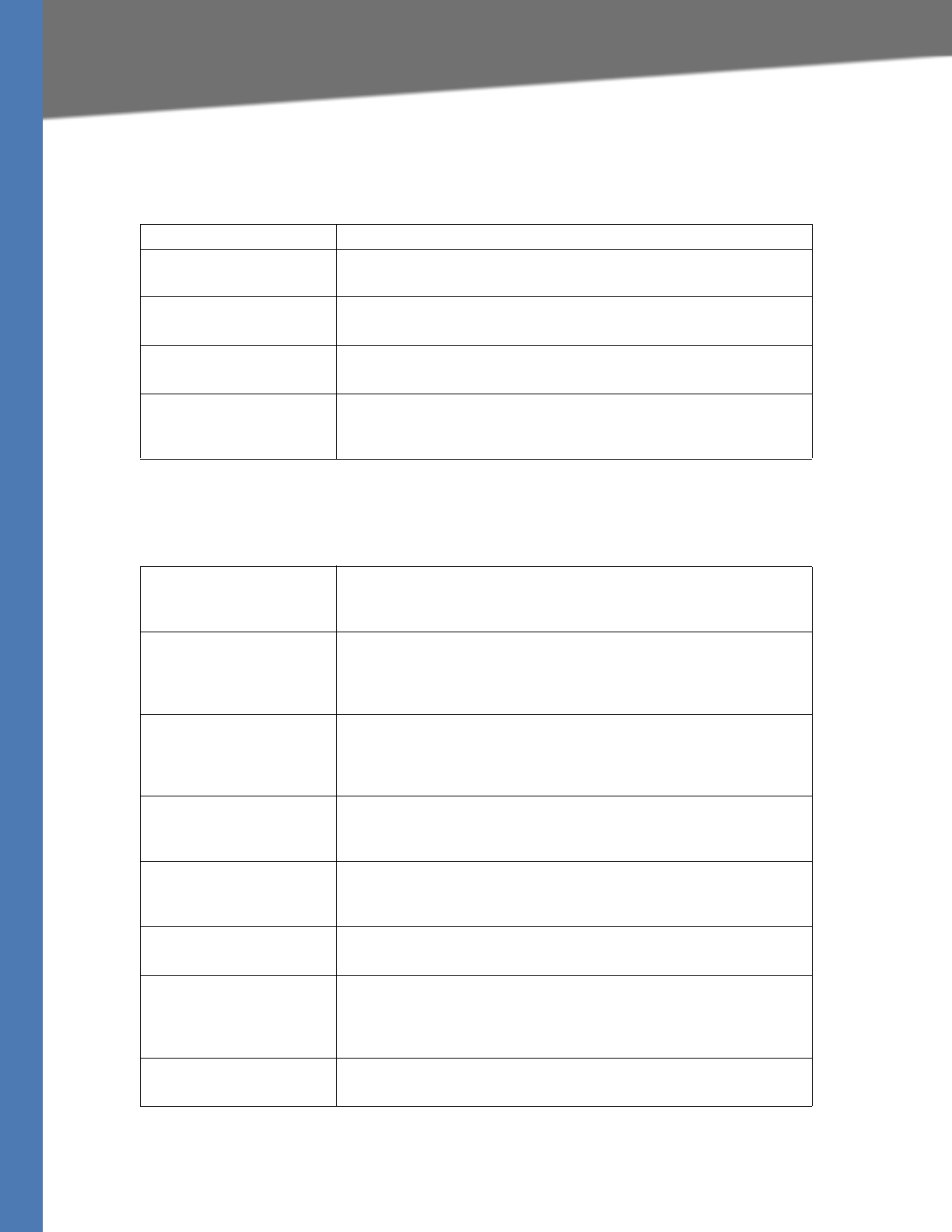
Linksys Voice System Administration Guide 180
Voice tab
Voice tab > Regional page
Ring and Call Waiting Tone Spec section
Voice tab > Regional page
Control Timer Values (sec) section
Field Description
Ring Waveform Waveform for the ringing signal: Sinusoid or Trapezoid.
Default: Trapezoid
Ring Frequency Frequency of the ringing signal. Valid values are 10–100 (Hz).
Default: 0
Ring Voltage Ringing voltage. 60–90 (V).
Default: 85
CWT Frequency Frequency script of the call waiting tone. All distinctive CWTs are based
on this tone.
Default: 440@-10
Hook Flash Timer Min Minimum on-hook time before off-hook qualifies as hook-flash. Less
than this the on-hook event is ignored. Range: 0.1–0.4 seconds.
Default: .1
Hook Flash Timer Max Maximum on-hook time before off-hook qualifies as hook-flash. More
than this the on-hook event is treated as on-hook (no hook-flash event).
Range: 0.4–1.6 seconds.
Default: .9
Callee On Hook Delay Phone must be on-hook for at this time in sec before the SPA9000 tears
down the current inbound call. It does not apply to outbound calls.
Range: 0–255 seconds.
Default: 0
Reorder Delay Delay after far end hangs up before reorder tone is played. 0 = plays
immediately, inf = never plays. Range: 0–255 seconds.
Default: 5
Call Back Expires Expiration time in seconds of a call back activation. Range: 0–65535
seconds.
Default: 1800
Call Back Retry Intvl Call back retry interval in seconds. Range: 0–255 seconds.
Default: 30
Call Back Delay Delay after receiving the first SIP 18x response before declaring the
remote end is ringing. If a busy response is received during this time, the
SPA9000 still considers the call as failed and keeps on retrying.
Default: .5
VMWI Refresh Intvl Interval between VMWI refresh to the CPE.
Default: 0
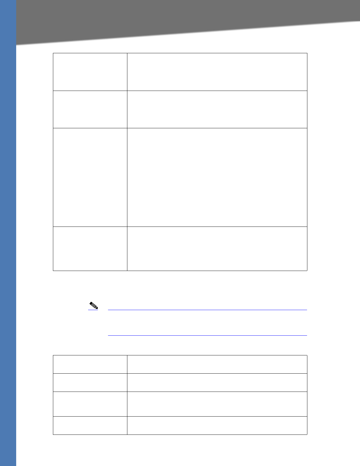
Linksys Voice System Administration Guide 181
Voice tab
Voice tab > Regional page
Vertical Service Activation Codes section
Note Vertical Service Activation Codes are automatically appended to the
dial-plan. There is no need to include them in dial-plan, although no
harm is done if they are included.
Interdigit Long Timer Long timeout between entering digits when dialing. The interdigit timer
values are used as defaults when dialing. The Interdigit_Long_Timer is
used after any one digit, if all valid matching sequences in the dial plan
are incomplete as dialed. Range: 0–64 seconds.
Default: 10
Interdigit Short Timer Short timeout between entering digits when dialing. The
Interdigit_Short_Timer is used after any one digit, if at least one
matching sequence is complete as dialed, but more dialed digits would
match other as yet incomplete sequences. Range: 0–64 seconds.
Default: 3
CPC Delay Delay in seconds after caller hangs up when the SPA9000 starts
removing the tip-and-ring voltage to the attached equipment of the
called party. Range: 0–255 seconds. SPA9000 has had polarity reversal
feature since release 1.0 which can be applied to both the caller and the
callee end. This feature is generally used for answer supervision on the
caller side to signal to the attached equipment when the call has been
connected (remote end has answered) or disconnected (remote end has
hung up). This feature should be disabled for the called party (in other
words, by using the same polarity for connected and idle state) and the
CPC feature should be used instead.
Without CPC enabled, reorder tone is played after a configurable delay.
If CPC is enabled, dial tone is played when tip-to-ring voltage is restored
Resolution is 1 second.
Default: 2
CPC Duration Duration in seconds for which the tip-to-ring voltage is removed after
the caller hangs up. After that, tip-to-ring voltage is restored and dial
tone applies if the attached equipment is still off-hook. CPC is disabled if
this value is set to 0. Range: 0 to 1.000 second. Resolution is 0.001
second.
Default: 0 (CPC disabled)
Call Return Code This code calls the last caller.
Default: *69
Call Redial Code Redials the last number called.
Default: *07
Blind Transfer Code Begins a blind transfer of the current call to the extension specified after
the activation code.
Default: *98
Call Back Act Code Starts a callback when the last outbound call is not busy.
Default: *66

Linksys Voice System Administration Guide 182
Voice tab
Call Back Deact Code Cancels a callback.
Default: *86
Call Back Busy Act Code Starts a callback when the last outbound call is busy.
Default: *05
Cfwd All Act Code Forwards all calls to the extension specified after the activation code.
Default: *72
Cfwd All Deact Code Cancels call forwarding of all calls.
Default: *73
Cfwd Busy Act Code Forwards busy calls to the extension specified after the activation code.
Default: *90
Cfwd Busy Deact Code Cancels call forwarding of busy calls.
Default: *91
Cfwd No Ans Act Code Forwards no-answer calls to the extension specified after the activation
code.
Default: *92
Cfwd No Ans Deact Code Cancels call forwarding of no-answer calls.
Default: *93
Cfwd Last Act Code Forwards the last inbound or outbound calls to the extension specified
after the activation code.
Default: *63
Cfwd Last Deact Code Cancels call forwarding of the last inbound or outbound calls.
Default: *83
Block Last Act Code Blocks the last inbound call.
Default: *60
Block Last Deact Code Cancels blocking of the last inbound call.
Default: *80
Accept Last Act Code Accepts the last outbound call. It lets the call ring through when do not
disturb or call forwarding of all calls are enabled.
Default: *64
Accept Last Deact Code Cancels the code to accept the last outbound call.
Default: *84
CW Act Code Enables call waiting on all calls.
Default: *56
CW Deact Code Disables call waiting on all calls.
Default: *57
CW Per Call Act Code Enables call waiting for the next call.
Default: *71
CW Per Call Deact Code Disables call waiting for the next call.
Default: *70
Block CID Act Code Blocks caller ID on all outbound calls.
Default: *67
Block CID Deact Code Removes caller ID blocking on all outbound calls.
Default: *68

Linksys Voice System Administration Guide 183
Voice tab
Block CID Per Call Act Code Blocks caller ID on the next outbound call.
Default: *81
Block CID Per Call Deact
Code
Removes caller ID blocking on the next inbound call.
Default: *82
Block ANC Act Code Blocks all anonymous calls.
Default: *77
Block ANC Deact Code Removes blocking of all anonymous calls.
Default: *87
DND Act Code Enables the do not disturb feature.
Default: *78
DND Deact Code Disables the do not disturb feature.
Default: *79
CID Act Code Enables caller ID generation.
Default: *65
CID Deact Code Disables caller ID generation.
Default: *85
CWCID Act Code Enables call waiting, caller ID generation.
Default: *25
CWCID Deact Code Disables call waiting, caller ID generation.
Default: *45
Dist Ring Act Code Enables the distinctive ringing feature.
Default: *26
Dist Ring Deact Code Disables the distinctive ringing feature.
Default: *46
Speed Dial Act Code Assigns a speed dial number.
Default: *74
Secure All Call Act Code Makes all outbound calls secure.
Default: *16
Secure No Call Act Code Makes all outbound calls not secure.
Default: *17
Secure One Call Act Code Makes the next outbound call secure. (It is redundant if all outbound
calls are secure by default.)
Default: *18
Secure One Call Deact Code Makes the next outbound call not secure. (It is redundant if all outbound
calls are not secure by default.)
Default: *19
Conference Act Code If this code is specified, the user must enter it before dialing the third
party for a conference call. Enter the code for a conference call.
Attn-Xfer Act Code If the code is specified, the user must enter it before dialing the third
party for a call transfer. Enter the code for a call transfer.
Modem Line Toggle Code Toggles the line to a modem.
Default: *99. Modem pass-through mode can be triggered only by pre-
dialing this code.

Linksys Voice System Administration Guide 184
Voice tab
FAX Line Toggle Code Toggles the line to a fax machine.
Default: #99
Referral Services Codes These codes tell the SPA9000 what to do when the user places the
current call on hold by hook flash and is listening to the second dial
tone.
One or more *codes can be configured into this parameter, such as *98,
or *97|*98|*123, etc. Max length is 79 chars. Each *code (and the
following valid target number according to current dial plan) entered on
the second dial-tone triggers the SPA9000 to perform a blind transfer to
a target number that is prepended by the service *code.
For example, after the user dials *98, the SPA9000 plays a special dial
tone called the Prompt Tone while waiting for the user the enter a target
number (which is checked according to dial plan as in normal dialing).
When a complete number is entered, the SPA9000 sends a blind REFER
to the holding party with the Refer-To target equals to
*98<target_number>. This feature allows the SPA9000 to hand off a call
to an application server to perform further processing, such as call park.
The *codes should not conflict with any of the other vertical service
codes internally processed by the SPA9000. You can empty the
corresponding *code that you do not want to SPA9000 to process.
Default: blank

Linksys Voice System Administration Guide 185
Voice tab
Voice tab > Regional page
Vertical Service Announcement Codes section
Feature Dial Services Codes These codes tell the Linksys ATA what to do when the user is
listening to the first or second dial tone.
One or more *code can be configured into this parameter, such as
*72, or *72|*74|*67|*82, etc. Max total length is 79 chars. This
parameter applies when the user has a dial tone (first or second
dial tone). Enter *code (and the following target number
according to current dial plan) entered at the dial tone triggers
the Linksys ATA to call the target number prepended by the
*code. For example, after user dials *72, the Linksys ATA plays a
prompt tone awaiting the user to enter a valid target number.
When a complete number is entered, the Linksys ATA sends a
INVITE to *72<target_number> as in a normal call. This feature
allows the proxy to process features like call forward (*72) or
BLock Caller ID (*67).
The *codes should not conflict with any of the other vertical
service codes internally processed by the Linksys ATA. You can
empty the corresponding *code that you do not want to Linksys
ATA to process.
You can add a parameter to each *code in Features Dial Services
Codes to indicate what tone to play after the *code is entered,
such as *72‘c‘|*67‘p‘. Below are a list of allowed tone parameters
(note the use of back quotes surrounding the parameter w/o
spaces)
• ‘c‘ = <Cfwd Dial Tone>
• ‘d‘ = <Dial Tone>
• ‘m‘ = <MWI Dial Tone>
• ‘o‘ = <Outside Dial Tone>
• ‘p‘ = <Prompt Dial Tone>
• ‘s‘ = <Second Dial Tone>
• ‘x‘ = No tones are place, x is any digit not used above
If no tone parameter is specified, the Linksys ATA plays Prompt
tone by default.
If the *code is not to be followed by a phone number, such as *73
to cancel call forwarding, do not include it in this parameter. In
that case, simple add that *code in the dial plan and the Linksys
ATA send INVITE *73@..... as usual when user dials *73.
Media Loopback Code Default: *03
Service Annc Base Number Base number for service announcements.
Service Annc Extension
Codes
Extension codes for service announcements.
Linksys Voice System Administration Guide 186
Voice tab
Voice tab > Regional page
Outbound Call Codec Selection Codes section
Note These codes automatically appended to the dial-plan. So no need to
include them in dial-plan (although no harm to do so either).
Prefer G711u Code Makes this codec the preferred codec for the associated call.
Default: *017110.
Force G711u Code Makes this codec the only codec that can be used for the associated call.
Default: *027110.
Prefer G711a Code Makes this codec the preferred codec for the associated call.
Default: *017111
Force G711a Code Makes this codec the only codec that can be used for the associated call.
Default: *027111.
Prefer G723 Code Makes this codec the preferred codec for the associated call.
Default: *01723.
Force G723 Code Makes this codec the only codec that can be used for the associated call.
Default: *02723.
Prefer G726r16 Code Makes this codec the preferred codec for the associated call.
Default: *0172616.
Force G726r16 Code Makes this codec the only codec that can be used for the associated call.
Default: *0272616.
Prefer G726r24 Code Makes this codec the preferred codec for the associated call.
Default: *0172624.
Force G726r24 Code Makes this codec the only codec that can be used for the associated call.
Default: *0272624.
Prefer G726r32 Code Makes this codec the preferred codec for the associated call.
Default: *0172632.
Force G726r32 Code Makes this codec the only codec that can be used for the associated call.
Default: *0272632.
Prefer G726r40 Code Makes this codec the preferred codec for the associated call.
Default: *0172640.
Force G726r40 Code Makes this codec the only codec that can be used for the associated call.
Default: *0272640.
Prefer G729a Code Makes this codec the preferred codec for the associated call.
Default: *01729.
Force G729a Code Makes this codec the only codec that can be used for the associated call.
Default: *02729.

Linksys Voice System Administration Guide 187
Voice tab
Voice tab > Regional page
Miscellaneous section
Set Local Date (mm/dd) Sets the local date (mm stands for months and dd stands for days). The
year is optional and uses two or four digits.
Default: blank
Set Local Time (HH/mm) Sets the local time (hh stands for hours and mm stands for minutes).
Seconds are optional.
Default: blank
Time Zone Selects the number of hours to add to GMT to generate the local time
for caller ID generation. Choices are GMT-12:00, GMT-11:00,…, GMT,
GMT+01:00, GMT+02:00, …, GMT+13:00.
Default: GMT-08:00
FXS Port Impedance Sets the electrical impedance of the FXS port. Choices are 600, 900,
600+2.16uF, 900+2.16uF, 270+750||150nF, 220+850||120nF,
220+820||115nF, or 200+600||100nF.
Default: 600
Daylight Saving Time Rule Enter the rule for calculating daylight saving time; it should include the
start, end, and save values. This rule is comprised of three fields. Each
field is separated by ; (a semicolon) as shown below. Optional values
inside [ ] (the brackets) are assumed to be 0 if they are not specified.
Midnight is represented by 0:0:0 of the given date.
SYNTAX: start = <start-time>; end=<end-time>; save = <save-time>
The <start-time> and <end-time> values specify the start and end dates
and times of daylight saving time. Each value is in this format: <month>
/<day> / <weekday>[/HH:[mm[:ss]]]
The <save-time> value is the number of hours, minutes, and/or seconds
to add to the current time during daylight saving time. The <save-time>
value can be preceded by a negative (-) sign if subtraction is desired
instead of addition. The <save-time> value is in this format: [/[+|-
]HH:[mm[:ss]]]
The <month> value equals any value in the range 1-12 (January-
December).
The <day> value equals [+|-] any value in the range 1-31.
If <day> is 1, it means the <weekday> on or before the end of the
month (in other words the last occurrence of < weekday> in that
month).
The <weekday> value equals any value in the range 1-7 (Monday-
Sunday). It can also equal 0. If the <weekday> value is 0, this means that
the date to start or end daylight saving is exactly the date given. In that
case, the <day> value must not be negative. If the <weekday> value is
not 0 and the <day> value is positive, then daylight saving starts or ends
on the <weekday> value on or after the date given. If the <weekday>
value is not 0 and the <day> value is negative, then daylight saving
starts or ends on the <weekday> value on or before the date given.
The abbreviation HH stands for hours (0-23).
The abbreviation mm stands for minutes (0-59).
The abbreviation ss stands for seconds (0-59).
The default Daylight Saving Time Rule is start=4/1/7;end=10/-1/
7;save=1.

Linksys Voice System Administration Guide 188
Voice tab
FXS Port Input Gain Input gain in dB, up to three decimal places. The range is 6.000 to -
12.000.
Default: -3.
FXS Port Output Gain Output gain in dB, up to three decimal places. The range is 6.000 to -
12.000. The Call Progress Tones and DTMF playback level are not
affected by the <FXS Port Output Gain>.
Default: -3
DTMF Playback Level Local DTMF playback level in dBm, up to one decimal place.
Default: -16.0
DTMF Playback Length Local DTMF playback duration in milliseconds.
Default: .1
Detect ABCD To enable local detection of DTMF ABCD, select yes. Otherwise, select
no. Setting has no effect if DTMF Tx Method is INFO; ABCD is always sent
OOB regardless in this setting.
Default: yes
Playback ABCD To enable local playback of OOB DTMF ABCD, select yes. Otherwise,
select no.
Default: yes
Caller ID Method The following choices are available:
Bellcore (N.Amer,China)—CID, CIDCW, and VMWI. FSK sent after first ring
(same as ETSI FSK sent after first ring) (no polarity reversal or DTAS).
DTMF (Finland, Sweden)—CID only. DTMF sent after polarity reversal
(and no DTAS) and before first ring.
DTMF (Denmark)—CID only. DTMF sent after polarity reversal (and no
DTAS) and before first ring.
ETSI DTMF—CID only. DTMF sent after DTAS (and no polarity reversal)
and before first ring.
ETSI DTMF With PR—CID only. DTMF sent after polarity reversal and
DTAS and before first ring.
ETSI DTMF After Ring—CID only. DTMF sent after first ring (no polarity
reversal or DTAS).
ETSI FSK—CID, CIDCW, and VMWI. FSK sent after DTAS (but no polarity
reversal) and before first ring. Waits for ACK from CPE after DTAS for
CIDCW.
ETSI FSK With PR (UK)—CID, CIDCW, and VMWI. FSK is sent after polarity
reversal and DTAS and before first ring. Waits for ACK from CPE after
DTAS for CIDCW. Polarity reversal is applied only if equipment is on
hook.
Default: Bellcore(N.Amer, China)
Caller ID FSK Standard The SPA9000 supports bell 202 and v.23 standards for caller ID
generation. Select the FSK standard you want to use, bell 202 or v.23.
Default: bell 202
Feature Invocation Method Select the method you want to use, Default or Sweden default.
Default: Default
More Echo Suppression Enable or disable more echo suppresion.
Default: no

Linksys Voice System Administration Guide 189
Voice tab
Voice tab >
FXS 1/2 page
You can use the FXS 1 page and the FXS 2 page to configure the settings for the FXS devices that
are connected to the Phone 1 and Phone 2 ports of the SPA9000.
•”Line Enable section,” on page 189
•”Network Settings section,” on page 189
•”SIP Settings section,” on page 190
•”Subscriber Information section,” on page 191
•”Dial Plan section,” on page 191
•”Mailbox Status section,” on page 191
•”Streaming Audio Server (SAS) section,” on page 192
•”Call Feature Settings section,” on page 192
•”Audio Configuration section,” on page 193
•”FXS Port Polarity Configuration section,” on page 196
Voice tab > FXS 1/2 page
Line Enable section
Voice tab > FXS 1/2 page
Network Settings section
Line Enable Enables this line for service (yes) or removes this line from service (no)
Default: yes
SIP ToS/DiffServ Value TOS/DiffServ field value in UDP IP packets carrying a SIP message.
Default: 0x68
SIP CoS Value [0-7] CoS value for SIP messages.
Default: 3
RTP ToS/DiffServ Value ToS/DiffServ field value in UDP IP packets carrying RTP data.
Default: 0xb8
RTP CoS Value [0-7] CoS value for RTP data.
Default: 6

Linksys Voice System Administration Guide 190
Voice tab
Voice tab > FXS 1/2 page
SIP Settings section
Network Jitter Level Determines how jitter buffer size is adjusted by the SPA9000. Jitter
buffer size is adjusted dynamically. The minimum jitter buffer size is 30
milliseconds or (10 milliseconds + current RTP frame size), whichever is
larger, for all jitter level settings. However, the starting jitter buffer size
value is larger for higher jitter levels. This setting controls the rate at
which the jitter buffer size is adjusted to reach the minimum. Select the
appropriate setting: low, medium, high, very high, or extremely high.
Default: high
Jitter Buffer Adjustment Controls how the jitter buffer should be adjusted. Select the appropriate
setting: up and down, up only, down only, or disable.
Default: up and down
SIP Port Port number of the SIP message listening and transmission port.
Default: 5080
SIP Remote-Party-ID To use the Remote-Party-ID header instead of the From header, select
yes. Otherwise, select no.
Default: yes
SIP Debug Option SIP messages are received at or sent from the proxy listen port. This
feature controls which SIP messages to log. The choices are as follows:
none—No logging.
1-line—Logs the start-line only for all messages.
1-line excl. OPT—Logs the start-line only for all messages except
OPTIONS requests/responses.
1-line excl. NTFY—Logs the start-line only for all messages except
NOTIFY requests/responses.
1-line excl. REG—Logs the start-line only for all messages except
REGISTER requests/responses.
1-line excl. OPT|NTFY|REG—Logs the start-line only for all messages
except OPTIONS, NOTIFY, and REGISTER
requests/responses.
full—Logs all SIP messages in verbose mode.
full excl. OPT—Logs all SIP messages in full text except OPTIONS
requests/responses.
full excl. NTFY—Logs all SIP messages in full text except NOTIFY
requests/responses.
full excl. REG—Logs all SIP messages in full text except REGISTER
requests/responses.
full excl. OPT|NTFY|REG—Logs all SIP messages in full text except for
OPTIONS, NOTIFY, and REGISTER requests/responses.
Default: none

Linksys Voice System Administration Guide 191
Voice tab
Voice tab > FXS 1/2 page
Subscriber Information section
Voice tab > FXS 1/2 page
Dial Plan section
Voice tab > FXS 1/2 page
Mailbox Status section
Restrict Source IP If line interfaces use the same SIP Port value and the Restrict Source IP
feature is enabled, the proxy IP address for Lines 1 and 2 is treated as an
acceptable IP address for both lines. To enable the Restrict Source IP
feature, select yes. Otherwise, select no.
A source IP address is untrusted if it does not match any of the IP
addresses resolved from the configured Proxy or Outbound Proxy if Use
Outbound Proxy is set to yes.
Default: no
Referor Bye Delay Controls when the SPA9000 sends BYE to terminate stale call legs after
completion of call transfers. Multiple delay settings (Referor, Refer
Target, Referee, and Refer-To Target) are configured on this screen. For
the Referor Bye Delay, enter the appropriate period of time in seconds.
Default: 4
Refer Target Bye Delay For the Refer Target Bye Delay, enter the appropriate period of time in
seconds.
Default: 0
Referee Bye Delay For the Referee Bye Delay, enter the appropriate period of time in
seconds.
Default: 0
Refer-To Target Contact To contact the refer-to target, select yes. Otherwise, select no.
Default: no
Sticky 183 If this feature is enabled, the IP telephony ignores further 180 SIP
responses after receiving the first 183 SIP response for an outbound
INVITE. To enable this feature, select yes. Otherwise, select no.
Default: no
Display Name Display name for caller ID.
User ID Extension number for this line.
Dial Plan Dial plan script for this line.
Message Waiting Indicates whether you have new voicemail waiting.

Linksys Voice System Administration Guide 192
Voice tab
Voice tab > FXS 1/2 page
Streaming Audio Server (SAS) section
Voice tab > FXS 1/2 page
Call Feature Settings section
SAS Enable To enable the use of the line as a streaming audio source, select yes.
Otherwise, select no. If enabled, the line cannot be used for outgoing
calls. Instead, it auto-answers incoming calls and streams audio RTP
packets to the caller.
Default: no
SAS DLG Refresh Intvl If this value is not zero, it is the interval at which the streaming audio
server sends out session refresh (SIP re-INVITE) messages to determine
whether the connection to the caller is still active. If the caller does not
respond to the refresh message, the SPA9000 ends this call with a SIP
BYE message. The range is 0 to 255 seconds (0 means that the session
refresh is disabled).
Default: 30
SAS Inbound RTP Sink This setting works around devices that do not play inbound RTP if the
streaming audio server line declares itself as a send-only device and tells
the client not to stream out audio. Enter a Fully Qualified Domain Name
(FQDN) or IP address of an RTP sink; this value is used by the SPA9000’s
streaming audio server line in the SDP of its 200 response to an inbound
INVITE message from a client.
The purpose of this parameter is to work around devices that do not
play inbound RTP if the SAS line declares itself as a “sendonly” device
and tells the client not to stream out audio. This parameter is a FQDN or
IP address of a RTP sink to be used by the SPA SAS line in the SDP of its
200 response to inbound INVITE from a client. It will appear in the c =
line and the port number and, if specified, in the m = line of the SDP. If
this value is not specified or equal to 0, then c = 0.0.0.0 and a=sendonly
is used in the SDP to tell the SAS client to not to send any RTP to this SAS
line. If a non-zero value is specified, then a=sendrecv and the SAS client
will stream audio to the given address. Special case: If the value is $IP,
then the SAS line’s own IP address is used in the c = line and a=sendrecv.
In that case the SAS client will stream RTP packets to the SAS line.
Default: blank
Blind Attn-Xfer Enable Enables the SPA9000 to perform an attended transfer operation by
ending the current call leg and performing a blind transfer of the other
call leg. If this feature is disabled, the SPA9000 performs an attended
transfer operation by referring the other call leg to the current call leg
while maintaining both call legs. To use this feature, select yes.
Otherwise, select no.
Default: no
MOH Server User ID or URL of the auto-answering streaming audio server. When only
a user ID is specified, the current or outbound proxy is contacted. Music-
on-hold is disabled if the MOH Server is not specified.
Xfer When Hangup Conf Makes the SPA9000 perform a transfer when a conference call has
ended. Select yes or no from the drop-down menu.
Default: Yes
Linksys Voice System Administration Guide 193
Voice tab
Voice tab > FXS 1/2 page
Audio Configuration section
Note A codec resource is considered as allocated if it has been included in the
SDP codec list of an active call, even though it eventually may not be the
one chosen for the connection. So, if the G.729a codec is enabled and
included in the codec list, that resource is tied up until the end of the call
whether or not the call actually uses G.729a. If the G729a resource is
already allocated and since only one G.729a resource is allowed per
device, no other low-bit-rate codec may be allocated for subsequent
calls; the only choices are G711a and G711u. On the other hand, two
G.723.1/G.726 resources are available per device.Therefore it is important
to disable the use of G.729a in order to guarantee the support of two
simultaneous G.723/G.726 codecs.
Conference Bridge URL This feature supports external conference bridging for n-way
conference calls (n > 2), instead of mixing audio locally. To use this
feature, set this parameter to that of the server's name; for example,
conf@myserver.com:12345 or conf (which uses the Proxy value as the
domain).
Default: blank
Conference Bridge Ports Maximum number of conference call participants. The range is 3 to 10.
Default: 3
Enable IP Dialing To use IP dialing, select yes. Otherwise, select no.
Default: no
Emergency Number Comma-separated list of emergency number patterns. If an outbound
call matches one of the patterns, the SPA9000 disables call waiting, hook
flash event handling, and fax tone detection. Operation is restored to
normal when the phone is on-hook again. If you leave this field blank,
the SPA9000 has no emergency number.
Mailbox ID Enter the ID number of the mailbox for this line.
Preferred Codec Preferred codec for all calls. (The actual codec used in a call still depends
on the outcome of the codec negotiation protocol.) Select one of the
following: G711u, G711a, G726-16, G726-24, G726-32, G726-40,
G729a, or G723
Default: G711u
Second Preferred Codec,
Third Preferred Codec
Other codecs to be preferred if the preferred codec is not available due
to the codec negotiation protocol.
Default: Unspecified
Use Pref Codec Only If set to yes, the call can be completed only with the preferred codec.
Default: no
Silence Supp Enable To enable silence suppression so that silent audio frames are not
transmitted, select yes. Otherwise, select no.
Default: no

Linksys Voice System Administration Guide 194
Voice tab
Use Pref Codec Only To use only the preferred codec for all calls, select yes. (The call fails if the
far end does not support this codec.) Otherwise, select no.
Default: no
Silence Threshold Select the appropriate setting for the threshold: high, medium, or low.
Default: medium
G729a Enable To enable the use of the G729a codec at 8 kbps, select yes. Otherwise,
select no.
Default: yes
Echo Canc Enable To enable the use of the echo canceller, select yes. Otherwise, select no.
Default: yes
G723 Enable To enable the use of the G723a codec at 6.3 kbps, select yes. Otherwise,
select no.
Default: yes
Echo Canc Adapt Enable To enable the echo canceller to adapt, select yes. Otherwise, select no.
Default: yes
G726-16 Enable To enable the use of the G726 codec at 16 kbps, select yes. Otherwise,
select no.
Default: yes
Echo Supp Enable To enable the use of the echo suppressor, select yes. Otherwise, select
no.
Default: yes
G726-24 Enable To enable the use of the G726 codec at 24 kbps, select yes. Otherwise,
select no.
Default: yes
FAX CED Detect Enable To enable detection of the fax Caller-Entered Digits (CED) tone, select
yes. Otherwise, select no.
Default: yes
G726-32 Enable To enable the use of the G726 codec at 32 kbps, select yes. Otherwise,
select no.
Default: yes
FAX CNG Detect Enable To enable detection of the fax Calling Tone (CNG), select yes. Otherwise,
select no.
Default: yes
G726-40 Enable To enable the use of the G726 codec at 40 kbps, select yes. Otherwise,
select no.
Default: yes
FAX Passthru Codec Select the codec for fax passthrough, G711u or G711a.
Default: G711u
DTMF Process INFO To use the DTMF process info feature, select yes. Otherwise, select no.
Default: yes
FAX Codec Symmetric To force the SPA9000 to use a symmetric codec during fax passthrough,
select yes. Otherwise, select no.
Default: yes
DTMF Process AVT To use the DTMF process AVT feature, select yes. Otherwise, select no.
Default: yes

Linksys Voice System Administration Guide 195
Voice tab
FAX Passthru Method Select the fax passthrough method: None, NSE, or ReINVITE.
Default: NSE
DTMF Tx Method Select the method to transmit DTMF signals to the far end: InBand, AVT,
INFO, Auto, InBand+INFO, or AVT+INFO. InBand sends DTMF using the
audio path. AVT sends DTMF as AVT events. INFO uses the SIP INFO
method. Auto uses InBand or AVT based on the outcome of codec
negotiation.
Default: Auto
DTMF Detection Mode Determines where to use Normal or Strict DTMF detection
Strict mode reduces the likelihood of false DTMF detection but requires
an extra hold time after detection. Also the DTMF level is raised. Under
strict mode, the minimum duration threshold is 60 and 90 ms for AVT
and SIP-INFO respectively. The level threshold is -20 dBm.
Default: Strict
FAX Process NSE To use the fax process NSE feature, select yes. Otherwise, select no.
Default: yes
Hook Flash Tx Method Select the method for signaling hook flash events: None, AVT, or INFO.
None does not signal hook flash events. AVT uses RFC2833 AVT (event =
16). INFO uses SIP INFO with the single line signal=hf in the message
body. The MIME type for this message body is taken from the Hook Flash
MIME Type setting.
Default: None
FAX Disable ECAN If enabled, this feature automatically disables the echo canceller when a
fax tone is detected. To use this feature, select yes. Otherwise, select no.
Default: no
Release Unused Codec This feature allows the release of codecs not used after codec
negotiation on the first call, so that other codecs can be used for the
second line. To use this feature, select yes. Otherwise, select no.
Default: yes
FAX Enable T38 To enable the use of the ITU-T T.38 standard for faxing, select yes.
Otherwise, select no.
Default: yes
FAX Tone Detect Mode This parameter has three possible values:
caller or callee - SPA will detect FAX tone whether it is callee or caller
caller only - SPA will detect FAX tone only if it is the caller
callee only - SPA will detect FAX tone only if it is the callee
Default: caller or callee
FAX T38 Redundancy The redundancy factor for the T.38 Fax Relay from 0 (none) to 4
Default: 1
FAX Tone Detect Mode: The method of fax tone dection: caller and callee, caller only, or callee
only
Default: caller or callee
NOTE: This setting allows a fax tone to be detected from either side of
the call.

Linksys Voice System Administration Guide 196
Line 1/2/3/4 page
Voice tab > FXS 1/2 page
FXS Port Polarity Configuration section
Voice tab >
Line 1/2/3/4 page
You can use the Line 1 - Line 4 pages to configure the line interfaces on your SPA9000. The line
interface page includes the following sections:
•”Line Enable section,” on page 196
•”Network Settings section,” on page 196
•”SIP Settings section,” on page 197
•”Subscriber Information section,” on page 199
•”Dial Plan section,” on page 199
•”NAT Settings section,” on page 199
•”Proxy and Registration section,” on page 200
Voice tab > Line page
Line Enable section
Voice tab > Line page
Network Settings section
Idle Polarity Polarity before a call is connected: Forward or Reverse.
Default: Forward
Caller Conn Polarity Polarity after an outbound call is connected: Forward or Reverse.
Default: Forward
Callee Conn Polarity Polarity after an inbound call is connected: Forward or Reverse.
Default: Forward
Line Enable To enable this line for service, select yes. Otherwise, select no.
Default: yes
SIP ToS/DiffServ Value TOS/DiffServ field value in UDP IP packets carrying a SIP message.
Default: 0x68
SIP CoS Value [0-7] CoS value for SIP messages.
Default: 3

Linksys Voice System Administration Guide 197
Line 1/2/3/4 page
Voice tab > Line page
SIP Settings section
RTP ToS/DiffServ Value ToS/DiffServ field value in UDP IP packets carrying RTP data.
Default: 0xb8
RTP CoS Value [0-7] CoS value for RTP data.
Default: 6
SIP Transport Options: UDP, TCP, or TLS
Default: UDP
SIP Port Port number of the SIP message listening and transmission port.
Default: 5060
SIP 100REL Enable To enable the support of 100REL SIP extension for reliable transmission
of provisional responses (18x) and use of PRACK requests, select yes.
Otherwise, select no.
Default: no
Auth Resync-Reboot If this feature is enabled, the SPA9000 authenticates the sender when it
receives the NOTIFY resync reboot (RFC 2617) message. To use this
feature, select yes. Otherwise, select no.
Default: yes
SIP Proxy-Require The SIP proxy can support a specific extension or behavior when it
detects this header from the user agent. If this field is configured and
the proxy does not support it, it responds with the message,
unsupported. Enter the appropriate header in the field provided.
Default: blank
SIP Remote-Party-ID To use the Remote-Party-ID header instead of the From header, select
yes. Otherwise, select no.
Default: yes
SIP GUID The Global Unique ID is generated for each line for each device. When it
is enabled, the SPA9000 adds a GUID header in the SIP request. The
GUID is generated the first time the unit boots up and stays with the
unit through rebooting and even factory reset. This feature was
requested by Bell Canada (Nortel) to limit the registration of SIP
accounts.
Default: no

Linksys Voice System Administration Guide 198
Line 1/2/3/4 page
SIP Debug Option SIP messages are received at or sent from the proxy listen port. This
feature controls which SIP messages to log. Choices are as follows:
none—No logging.
1-line—Logs the start-line only for all messages.
1-line excl. OPT—Logs the start-line only for all messages except
OPTIONS requests/responses.
1-line excl. NTFY—Logs the start-line only for all messages except
NOTIFY requests/responses.
1-line excl. REG—Logs the start-line only for all messages except
REGISTER requests/responses.
1-line excl. OPT|NTFY|REG—Logs the start-line only for all messages
except OPTIONS, NOTIFY, and REGISTER
requests/responses.
full—Logs all SIP messages in verbose mode.
full excl. OPT—Logs all SIP messages in full text except OPTIONS
requests/responses.
full excl. NTFY—Logs all SIP messages in full text except NOTIFY
requests/responses.
full excl. REG—Logs all SIP messages in full text except REGISTER
requests/responses.
full excl. OPT|NTFY|REG—Logs all SIP messages in full text except for
OPTIONS, NOTIFY, and REGISTER requests/responses.
Default: None
Restrict Source IP If line interfaces use the same SIP Port value and the Restrict Source IP
feature is enabled, the proxy IP address for Lines 1 and 2 is treated as an
acceptable IP address for both lines. To enable the Restrict Source IP
feature, select yes. Otherwise, select no. A source IP address is untrusted
if it does not match any of the IP addresses resolved from the configured
<Proxy> (or <Outbound Proxy> if <Use Outbound Proxy> is yes).
Default: no
Referor Bye Delay Controls when the SPA9000 sends BYE to terminate stale call legs upon
completion of call transfers. Multiple delay settings (Referor, Refer
Target, Referee, and Refer-To Target) are configured on this screen. For
the Referor Bye Delay, enter the appropriate period of time in seconds.
Default: 4
Refer Target Bye Delay For the Refer Target Bye Delay, enter the appropriate period of time in
seconds.
Default: 0
Referee Bye Delay For the Referee Bye Delay, enter the appropriate period of time in
seconds.
Default: 0
Refer-To Target Contact To contact the refer-to target, select yes. Otherwise, select no.
Default: no
Auth INVITE When enabled, authorization is required for initial incoming INVITE
requests from the SIP proxy.

Linksys Voice System Administration Guide 199
Line 1/2/3/4 page
Voice tab > Line page
Subscriber Information section
Voice tab > Line page
Dial Plan section
Voice tab > Line page
NAT Settings section
Display Name Display name for caller ID.
User ID User ID assigned by the ITSP, often the same as the DID.
Password Password for this User ID.
Use Auth ID To use the authentication ID and password for SIP authentication, select
yes. Otherwise, select no to use the user ID and password.
Default: no
Auth ID Authentication ID for SIP authentication.
Call Capacity Maximum number of calls allowed on this line interface. You can set a
value from 1 to 15, or leave the setting as unlimited. Note that the
SPA9000 does not distinguish between incoming and outgoing calls
when talking about call capacity. Note: unlimited = 16.
Default: unlimited
Contact List List of client stations that the SPA9000 alerts when there is an incoming
call to the line interface from the ITSP.
Cfwd No Ans Delay Delay, in seconds, before the call forwarding of no-answer calls feature is
triggered.
Default: 20
Dial Plan Dial plan script for this line.
Default: (xx.) The Dial Plan strips off the steering digit prior to sending
the dialed number to the ITSP.
NAT Mapping Enable To use externally mapped IP addresses and SIP/RTP ports in SIP
messages, select yes. Otherwise, select no.
Default: no
NAT Keep Alive Enable To send the configured NAT keep alive message periodically, select yes.
Otherwise, select no.
Default: no
NAT Keep Alive Msg Enter the keep alive message that should be sent periodically to
maintain the current NAT mapping. If the value is $NOTIFY, a NOTIFY
message is sent. If the value is $REGISTER, a REGISTER message without
contact is sent.
Default: $NOTIFY

Linksys Voice System Administration Guide 200
Line 1/2/3/4 page
Voice tab > Line page
Proxy and Registration section
NAT Keep Alive Dest Destination that should receive NAT keep alive messages. If the value is
$PROXY, the messages are sent to the current or outbound proxy.
Default: $PROXY
EXT SIP Port Enter the port number of the external port to substitute for the actual
SIP port of the SPA9000 in all outgoing SIP messages.
Default: blank
Proxy SIP proxy server for all outbound requests.
Default: blank
Outbound Proxy SIP Outbound Proxy Server where all outbound requests are sent as the
first hop.
Use Outbound Proxy Enable the use of <Outbound Proxy>. If set to no, <Outbound Proxy>
and <Use OB Proxy in Dialog) is ignored.
Default: no
Use OB Proxy In Dialog Whether to force SIP requests to be sent to the outbound proxy within a
dialog. Ignored if <Use Outbound Proxy> is no or <Outbound Proxy> is
empty.
Default: yes
Register Enable periodic registration with the <Proxy>. This parameter is ignored
if <Proxy> is not specified.
Default: yes
Make Call Without Reg Allow making outbound calls without successful (dynamic) registration
by the unit. If No, dial tone will not play unless registration is successful.
Default: no
Register Expires Allow answering inbound calls without successful (dynamic)
registration by the unit. If proxy responded to REGISTER with a smaller
Expires value, the SPA9000 will renew registration based on this smaller
value instead of the configured value. If registration failed with an
Expires too brief error response, the SPA9000 will retry with the value
given in the Min-Expires header in the error response.
Default: 3600
Recommended: 60
Ans Call Without Reg Expires value in sec in a REGISTER request. SPA9000 will periodically
renew registration shortly before the current registration expired. This
parameter is ignored if <Register> is no. Values are yes or no.
Use DNS SRV Whether to use DNS SRV lookup for Proxy and Outbound Proxy.
Default: no
DNS SRV Auto Prefix If enabled, the SPA9000 will automatically prepend the Proxy or
Outbound Proxy name with _sip._udp when performing a DNS SRV
lookup on that name.
Default: no

Linksys Voice System Administration Guide 201
Line 1/2/3/4 page
Proxy Fallback Intvl This parameter sets the delay (sec) after which the SPA9000 will retry
from the highest priority proxy (or outbound proxy) servers after it has
failed over to a lower priority server. This parameter is useful only if the
primary and backup proxy server list is provided to the SPA9000 via DNS
SRV record lookup on the server name. (Using multiple DNS A record per
server name does not allow the notion of priority and so all hosts are
considered at the same priority and the SPA9000 will not attempt to fall
back after a fail over).
Default: 3600
Proxy Redundancy Method SPA9000 will make an internal list of proxies returned in DNS SRV
records. In normal mode, this list will contain proxies ranked by weight
and priority.
If based on SRV, the port is configured, the SPA9000 does normal first
and also inspects the port number based on 1st proxy’s port in the list.
Default: Normal
Mailbox Status The status of the connection to the voice mail server
Mailbox status for all the mailboxes associated with this line interface.
The status is automatically updated when the SPA9000 receives
voicemail status notification from the ITSP.
Format: [mbs[,mbs[,mbs[,…]]]] where:
mbs = mbid:new/old
mbid = mailbox ID, such as 12345
new = number of new messages in mailbox: 0,1,2,…
old = number of old messages in mailbox: 0, 1, 2, …
Mailbox Subscribe URL Note: This parameter allows $USER and $PROXY macros, such as
$USER@$PROXY
Mailbox Deposit URL This parameter allows $USER, $PROXY, and $MBID macros, such as
$USER@$PROXY, or $MBID@$PROXY.
Default: blank
Mailbox Subscribe Expires Identifies when the mailbox subscription expires.
Recommended: 30
Mailbox Manage URL This parameter allows $USER, $PROXY, and $MBID macros, such as
$USER@$PROXY, or $MBID@$PROXY.
Default: blank

Linksys Voice System Administration Guide 202
Line 1/2/3/4 page
VMSP Bridge Applies only if this line interface offers voice mail services. It specifies
whether the SPA9000 should bridge the call from an external caller on
the same or a different line interface. The choices are:
None—Do not bridge external calls from any line interfaces
All—Bridge external calls from any line interfaces except from the same
line
All+Self—Bridge external calls from any line interfaces including the
same line
Notes:
If the external call is also on this line interface, the SPA9000 does not
attempt to bridge the call even if the value is All.
If <PBX Network Interface> is WAN, <Force Media Proxy> must be yes
for VMSP Bridging to function properly.
Default: None
CFWD Bridge Mode Instructs the SPA9000 how to handle call forwarding of an external
caller to another external number by a client station.
The normal way of performing this operation is for the SPA9000 to send
a (blind) SIP REFER to the calling device to let it contact the target
number directly. It then drops out of the call completely. This requires
the calling device to understand the SIP signaling involved and the
operation permitted by the underlying service provider. The SPA400, for
instance, cannot handle this operation.
With bridging, the SPA9000 maintains two separate call legs throughout
the call: one with the caller and one with the call forward target. The two
call peers connect only with the SPA9000, while the SPA9000 acts as a
proxy for the RTP packets exchanged between the two parties.
This parameter has two possible values:
None—Do not bridge forwarded calls (use the normal REFER method)
All—Bridge all forwarded calls
Default: None
XFER Bridge Mode Instructs the SPA9000 how to handle call transferring of an external
caller to another external number by a client station.
The normal way of performing this operation is for the SPA9000 to send
a SIP REFER method to the calling device to let it contact the transfer
target directly. The SPA9000 then drops out of the call completely. This
requires the calling device (the transferee) and the target device to
understand the SIP signaling involved and the operation permitted by
the underlying service providers. Note that the call legs with transferee
and the transfer target might be with different ITSP. The SPA400, for
instance, cannot handle this operation.
With bridging, the SPA9000 maintains two separate call legs throughout
the call: one with the transferred call and one with the transfer target.
The two call peers connect only with the SPA9000, while the SPA9000
acts as a proxy for the RTP packets exchanged between the two parties.
This parameter has three possible values:
none —Do not bridge call transfer (use the normal REFER method)
all —Bridge all call transfer
all except same line—Bridge call transfer only if it is between 2 different
Line interfaces

Linksys Voice System Administration Guide 203
CSetup
SPA400 Field Reference
This appendix describes the fields on each page of thes of the SPA400 administration web
server.
•”Setup,” on page 203
•”Administration,” on page 209
•”Status,” on page 211
•”Event Logs,” on page 212
Setup
This section describes the fields on the following pages within the Setup module:
•”Basic Setup,” on page 203
•”SPA9000 Interface,” on page 204
•”Voice,” on page 205
•”Voicemail Server,” on page 208
•”Voicemail Users,” on page 209
Setup tab
Basic Setup
Network Setup
Dynamic IP Address (DHCP
Client)
Select this button to obtain an IP address through DHCP. Fixed IP
address is the recommended setting.
Default setting: Dynamic IP Address
Fixed IP Address Select this button to assign a static IP address to the SPA400. This is the
recommended configuration.
IP Subnet Mask Subnet mask
Gateway IP Address IP address of the Gateway/Router
Domain Name Server (DNS) Address
Primary DNS IP address of the primary domain name server
Secondary DNS IP address of the secondary domain name server

Linksys Voice System Administration Guide 204
Setup
Setup tab
SPA9000 Interface
NTP
NTP Server 1 IP address or FQDN of a NTP server
Time Zone Select the time zone
Syslog Server The IP address of the syslog server to which the SPA9000 sends syslog
messages. Leave blank if you do not want to receive syslog messages.
SPA9000 User ID
User ID The User ID of the SPA9000
This value must be identical to the User ID that is entered on the
SPA9000 line interface page for this SPA400 device.
SPA 9000 Address
Discover Automatically Select this radio button if you want the SPA400 to learn the SPA9000 IP
address and port number from the SIP registration packet.
(Recommended)
Static Address Select this radio button to enter the IP address of SPA9000. Specify the
IP Address and Port in the provided fields.
IP Address IP address of the SPA9000
Port UDP port number that the SPA9000 uses to register to the SPA400
Default: 5060
Port ID
Port ID 1 A unique ID for the Line 1 port, too allow the SPA9000 to identify
incoming calls from the PSTN
Default: FXO_Port_ID_1
Port ID 2 A unique ID for the Line 2 port, too allow the SPA9000 to identify
incoming calls from the PSTN
Default: FXO_Port_ID_2
Port ID 3 A unique ID for the Line 3 port, too allow the SPA9000 to identify
incoming calls from the PSTN
Default: FXO_Port_ID_3
Port ID 4 A unique ID for the Line 4 port, too allow the SPA9000 to identify
incoming calls from the PSTN
Default: FXO_Port_ID_4

Linksys Voice System Administration Guide 205
Setup
Setup tab
Voice
NOTE: The default settings should be sufficient in most use cases. These settings should be
adjusted only after consultation with a service technician for the telephone company. It is
essential that these settings are compatible with those of the Central Office.
Signaling
Signaling Port The UDP port that the SPA400 uses to listen for incoming call setup
requests
Default: 5060
RTP
RTP Port The base UDP port for the block of UDP ports that that the SPA400 uses
to send and receive RTP and RTCP packets
Default: 10000
IP Tos/DiffServ
Call Signaling Packets TOS field in IP header for outgoing SIP packets
Default: 68
RTP Packets TOS field in IP header for outgoing RTP/RTCP packets
Default: b8
Session
Enable Session Timer Enables the SPA400 to encode the Timer header in all INVITE requests
for ringing timeout (checked by default)
Desired Refresh Time Desired session timer in seconds (0 by default)
Minimum Refresh Time Minimum value of the session timer in seconds (0 by default)
Voice Codecs
Preferred Codecs
Preferred Codec The preferred voice codec that SPA400 uses to negotiate with remote
VoIP devices to determine the voice codec for a call: G.711U, G.711A, or
G.729
Voice Codecs
Packetization The packetization time in milliseconds for each codec: G.711U, G.711A,
G.729
VAD Voice Activity Detection (OFF or ON)
Default: OFF
Linksys Voice System Administration Guide 206
Setup
Voice Setting
Calling Timers
Wait-for-Answer time The time in seconds that the SPA400 waits for the called party to
answer the call before terminating the call automatically
The maximum value is 100 seconds.
Default: 180
Call Limit The maximum time that a call can continue before it is terminated
automatically
Default: 65535
Dialing Parameters
Tone out on The duration in milliseconds of each tone in a DTMF sequence
Default: 200
Tone out off The number of milliseconds that elapses between successive digits in a
DTMF sequence
Default: 200
DTMF power The power level in 0.1 dBm of the DTMF tones
Default: -130
Answer after The number of rings that occur before the SPA400 answers an
incoming call
The maximum value is 2 rings.
Default: 2
Dial out wait The number of milliseconds that elapse after the SPA400 seizes a
telephony port and before the SPA400 sends DTMF digits
Default: 400
Dial out battery threshold The minimum voltage level that the SPA400 must detect on a
telelphony port before seizing a telephony port for an outbound call
Default: 20
Line Settings
Transmit Gain The gain level that the SPA400 may use to increase or attenuate the
power level before transmitting to the telephony port
NOTE: Change this setting if remote call participants have trouble
hearing the LVS users. Make changes in increments of 3 dB; changes of
less than 3 dB will not have a perceptible impact.
Default: 0
Receive Gain The gain level that the SPA400 may use to increase or attenuate the
power level before receiving on the telephony port
NOTE: The default Receive Gain settings should be satisfactory in most
use cases. Unnecessary changes in Receive Gain can cause problems
with echo.
Default: 0

Linksys Voice System Administration Guide 207
Setup
Impedance The impedance of the lines that are connected to SPA400’s telephony
ports
Default: 600 Ohms
Tip/Ring voltage The tip-to-ring voltage reserved for voice transmission
Default: 3.5 Volts
Operational loop current
Min
The minimum loop current that maintains an off-hook state. If the loop
current drops below this value, the phone enters on hook state.
Default: 10 mA
On-Hook speed The time that the loop current drops to 0mA when the phone enters
the on-hook state.
Default: Less than 0.5ms
Ring frequency Min The minimum frequency of a valid ring
Default: 10
Ring frequency Max The maximum frequency of a valid ring
Default: 100
Ring Validation Time The minimum duration of a valid ring
Default: 256ms
Ring Indication Delay The delay in reporting the ring after it presents on the PSTN line
Default: 512ms
Ring Timeout The delay on reporting that the ring stopped after it no longer presents
on the PSTN line
Default: 640ms
Ring Threshold The minimum voltage(rms value) of a valid ring
Default: 13.5-16.5vrms
Ringer Impedance Default: High
DC current Limiting
Default: Enable
Caller Id & CP Tone Method The regional settings for Caller ID and call progress tones
Default: North American
Battery reversal as
discconnect signal
Can be chosen as a method for signalling the end of a call
Default: unselected
Loop period shut-down as
disconnect signal
Can be chosen as a method for signalling the end of a call
Default: selected
Minimum period for
disconnect signal
The minimum duration that the loop current is cut off to signal the end
of the call; used with the loop period shut-down method
Default: 750
Linksys Voice System Administration Guide 208
Setup
Setup tab
Voicemail Server
Tear down FXO port when
silence detected for
The duration of silence that causes the FXO port to disconnect the call
Default: 300
Voicemail Settings
Server Port The UDP port this is open to receive packets
NOTE: This port number must be different from the signaling port on
the SPA9000 line interface. This port appears in the various mailbox
URL fields on the SPA9000 line interface page.
Default: 5090
SPA9000 subscriber ID The ID that the SPA9000 uses to subscribe to the SPA400 voice mail
server to obtain notifications
NOTE: This value appears in the Proxy and Registration: Mailbox
Subscribe URL field on the SPA9000 line interface page.
Example
• SPA9000 subscriber ID: 8888
•Mailbox Subscribe URL: 8888@192.168.0.110:5090
Default: 8888
Mailbox deposit number The phone number that the SPA9000 uses to deposit voice mail
NOTE: This value appears in the Proxy and Registration: Mailbox Deposit
URL field on the SPA9000 line interface page.
Example
• Mailbox deposit number: 900
•Mailbox Deposit URL: 900@192.168.0.110:5090
Default: 900
Mailbox manage number The phone number that the SPA9000 uses to access voice mail
NOTE: This value appears in the Proxy and Registration: Mailbox Manage
URL field on the SPA9000 line interface page.
Example
• Mailbox manage number: 800
•Mailbox Manage URL: 800@192.168.0.110:5090
Default: 800
AA Language The language that is used by the voice mail Auto Attendant: English,
German, Spanish, French, Dutch, Portuguese, Czech
Default: English
Maximum length of a
voicemail message
The maximum number of seconds that can elapse before a voice mail
message is ended automatically
Default: 60
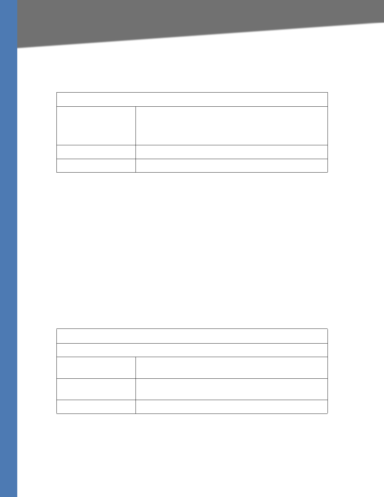
Linksys Voice System Administration Guide 209
Administration
Setup tab
Voicemail Users
Administration
This section describes the fields on the following pages within the Administration module:
•”Management,” on page 209
•”Factory Default,” on page 210
•”USB Setting,” on page 210
•”Firmware Upgrade,” on page 210
•”Reboot,” on page 210
Administration tab
Management
User Setting
Enable User NEnables the mailbox
Notes: Each mailbox can be assigned to a client station that is
managed by the SPA9000. Before a station can deposit and access
voicemail, the mail box ID must be configured through the Ext N page.
User ID The mailbox ID
Password The password for the mailbox
Gateway Access
Local Access
Gateway Username The user name that is entered to log on to the SPA400 web
configuration utility (default = Admin)
Gateway Password The password that is entered to log on to the SPA400 web configuraton
utility (default = blank)
Re-enter to Confirm If you entered a new password, retype it in this field.

Linksys Voice System Administration Guide 210
Administration
Administration tab
Factory Default
Administration tab
USB Setting
Administration tab
Firmware Upgrade
Administration tab
Reboot
Restore Factory
Defaults
Erases the current settings and resets the SPA400 to the original factory
default settings
USB Device
USB status The status of the USB storage device: mount (file system mounted and
available) or unmount
I want to reset USB (check
box)
Reset (button)
Erases the voice mail messages that are stored on the USB
Firmware Upgrade
File Path The file path to the firmware file that you want to install, as selected by
using the Browse button
Browse Allows you to select a firmware file on your PC, and populates the File
Path field
Upgrade Starts the Firmware upgrade, using the file that is specified in the File
Path field
Restart System Restarts the SPA400
NOTE: All SPA400 connections will be broken.
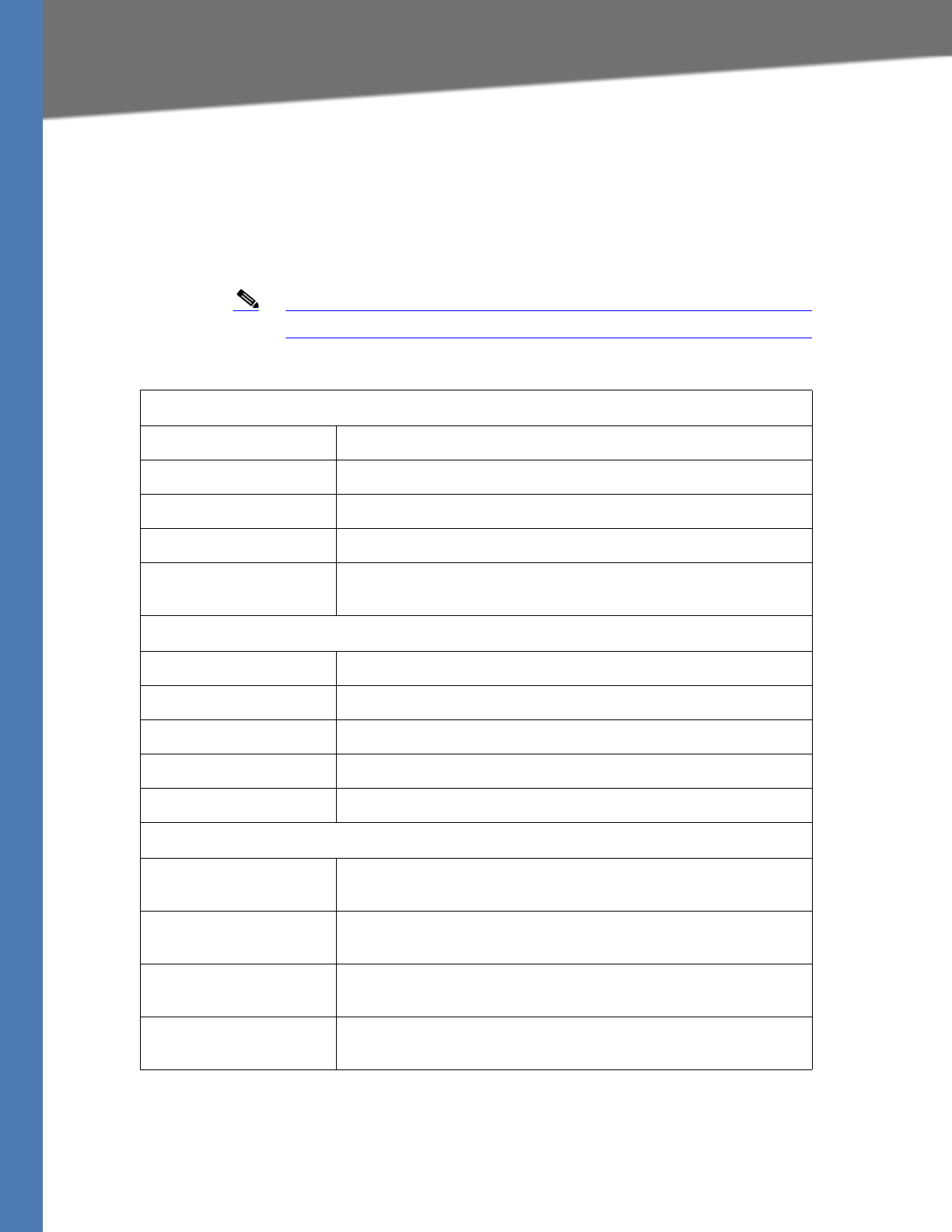
Linksys Voice System Administration Guide 211
Status
Status
Status tab
Gateway
Note This page is read only. No changes can be made.
Gateway Information
Firmware Version The firmware version that is installed on this device
Build Date The date when the firmware was last updated
MAC Address The MAC address of this device
Current Time The current date and time
System Up Time The length of time that the system has been operating, in days, hours,
and minutes
Internet Connection
IP Addres The IP address of this device
IP Subnet Mask The subnet mask for this subnet
Gateway IP Address The IP address of the gateway device
Primary DNS The primary DNS server
Secondary DNS The secondary DNS server
SPA400 Status
USB status The status of the USB storage device: mount (file system mounted and
available) or unmount
Voice mail status The status of the voice mail service; OK indicates that voice mail service
is enabled
USB capacity status The amount of storage space that is currently in use, and the amount
that is remaining, example: Used 5712KB, remaining 119960KB
SIP registration status The status of the SIP registration; Registered indicates that the SPA9000
is registered to the SPA400
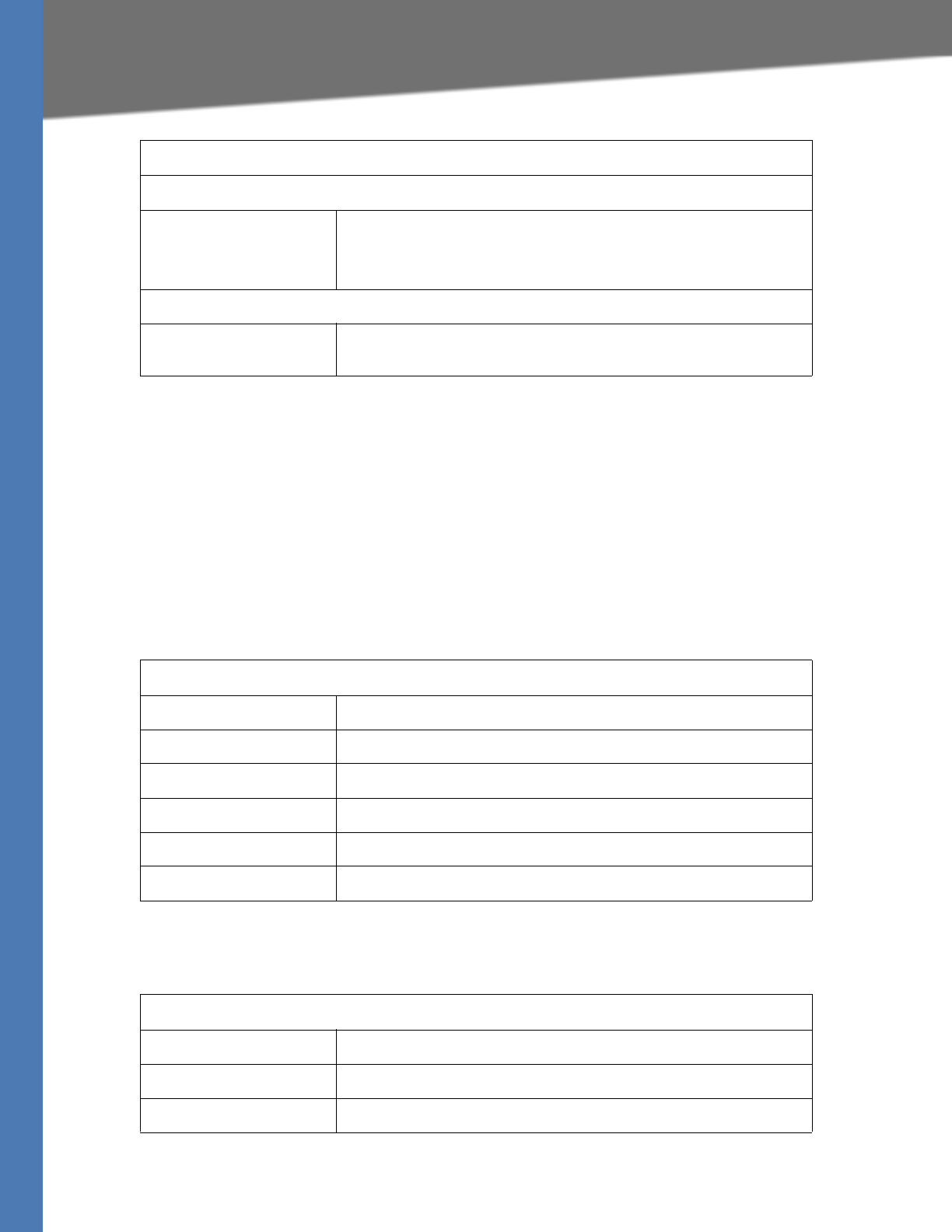
Linksys Voice System Administration Guide 212
Event Logs
Event Logs
This section describes the fields on the SetLog Level page.
Event Logs tab
Set Log Level
SPA400 logs significant events onto its internal buffer. For each log type, you can choose to
include Fatal Errors, Errors, Events, or All Information. Another option is OFF, meaning that no
information is collected for the selected log type.
Tone
FXO Line status
Hook Status
Line status (1-4) The status of each line port:
• On-Hook indicates that the FXO port is not in use.
• Off-Hook indicates that a call is in progress.
Battery Level
Line (1-4) The currently voltage on the line port, if the port is connected to a
PSTN line; for example, a connected line could show -51 V
Event Log Level
Telephony Log level for telephony events
SIP Log level for SIP events
DSP Log level for DSP events
Dial plan Log level for dial plan events
Voice mail Log level for voice mail events
Others Log level for all other events
Call process tone configuration
Tone on fraction The duty cycle of the CP tone to be detected
High cutoff frequency The highest frequency of a valid CP tone
Low cutoff frequency The lowest frequency of a valid CP tone

Linksys Voice System Administration Guide 213
Tone
Call process tone
detection
Tone Setting
Detection time The cadence of the CP tone to be detected; if the tone's cadence
matches the time length as in the edit boxes, it is considered a valid CP
tone
Repeat
Repeat count The number of times that the cadence needs to repeat to be
considered as a valid CP tone.

Linksys Voice System Administration Guide 214
DLimited Warranty
Warranty Information
Limited Warranty
Linksys warrants this Linksys hardware product against defects in materials and workmanship
under normal use for the Warranty Period, which begins on the date of purchase by the original
end-user purchaser and lasts for the period specified for this product at www.linksys.com/
warranty. The internet URL address and the web pages referred to herein may be updated by
Linksys from time to time; the version in effect at the date of purchase shall apply.
This limited warranty is non-transferable and extends only to the original end-user purchaser.
Your exclusive remedy and Linksysf entire liability under this limited warranty will be for
Linksys, at its option, to (a) repair the product with new or refurbished parts, (b) replace the
product with a reasonably available equivalent new or refurbished Linksys product, or (c)
refund the purchase price of the product less any rebates. Any repaired or replacement
products will be warranted for the remainder of the original Warranty Period or thirty (30) days,
whichever is longer. All products and parts that are replaced become the property of Linksys.
Exclusions and Limitations
This limited warranty does not apply if: (a) the product assembly seal has been removed or
damaged, (b) the product has been altered or modified, except by Linksys, (c) the product
damage was caused by use with non.Linksys products, (d) the product has not been installed,
operated, repaired, or maintained in accordance with instructions supplied by Linksys, (e) the
product has been subjected to abnormal physical or electrical stress, misuse, negligence, or
accident, (f ) the serial number on the Product has been altered, defaced, or removed, or (g) the
product is supplied or licensed for beta, evaluation, testing or demonstration purposes for
which Linksys does not charge a purchase price or license fee.
ALL SOFTWARE PROVIDED BY LINKSYS WITH THE PRODUCT, WHETHER FACTORY LOADED ON
THE PRODUCT OR CONTAINED ON MEDIA ACCOMPANYING THE PRODUCT, IS PROVIDED gAS
ISh WITHOUT WARRANTY OF ANY KIND. Without limiting the foregoing, Linksys does not
warrant that the operation of the product or software will be uninterrupted or error free. Also,
due to the continual development of new techniques for intruding upon and attacking
networks, Linksys does not warrant that the product, software or any equipment, system or
network on which the product or software is used will be free of vulnerability to intrusion or
attack. The product may include or be bundled with third party software or service offerings.
This limited warranty shall not apply to such third party software or service offerings. This
limited warranty does not guarantee any continued availability of a third party’s service for
which this product’s use or operation may require.
TO THE EXTENT NOT PROHIBITED BY LAW, ALL IMPLIED WARRANTIES AND CONDITIONS OF
MERCHANTABILITY, SATISFACTORY QUALITY OR FITNESS FOR A PARTICULAR PURPOSE ARE
LIMITED TO THE DURATION OF THE WARRANTY PERIOD. ALL OTHER EXPRESS OR IMPLIED
CONDITIONS, REPRESENTATIONS AND WARRANTIES, INCLUDING, BUT NOT LIMITED TO, ANY
IMPLIED WARRANTY OF NON-INFRINGEMENT, ARE DISCLAIMED. Some jurisdictions do not
allow limitations on how long an implied warranty lasts, so the above limitation may not apply
to you. This limited warranty gives you specific legal rights, and you may also have other rights
which vary by jurisdiction.

Linksys Voice System Administration Guide 215
Obtaining Warranty Service
TO THE EXTENT NOT PROHIBITED BY LAW, IN NO EVENT WILL LINKSYS BE LIABLE FOR ANY LOST
DATA, REVENUE OR PROFIT, OR FOR SPECIAL, INDIRECT, CONSEQUENTIAL, INCIDENTAL OR
PUNITIVE DAMAGES, REGARDLESS OF THE THEORY OF LIABILITY (INCLUDING NEGLIGENCE),
ARISING OUT OF OR RELATED TO THE USE OF OR INABILITY TO USE THE PRODUCT (INCLUDING
ANY SOFTWARE), EVEN IF LINKSYS HAS BEEN ADVISED OF THE POSSIBILITY OF SUCH DAMAGES.
IN NO EVENT WILL LINKSYS’ LIABILITY EXCEED THE AMOUNT PAID BY YOU FOR THE PRODUCT.
The foregoing limitations will apply even if any warranty or remedy provided under this limited
warranty fails of its essential purpose. Some jurisdictions do not allow the exclusion or
limitation of incidental or consequential damages, so the above limitation or exclusion may not
apply to you.
Obtaining Warranty Service
If you have a question about your product or experience a problem with it, please go to
www.linksys.com/support where you will find a variety of online support tools and information
to assist you with your product. If the product proves defective during the Warranty Period,
contact the Value Added Reseller (VAR) from whom you purchased the product or Linksys
Technical Support for instructions on how to obtain warranty service. The telephone number
for Linksys Technical Support in your area can be found in the product User Guide and at
www.linksys.com. Have your product serial number and proof of purchase on hand when
calling. A DATED PROOF OF ORIGINAL PURCHASE IS REQUIRED TO PROCESS WARRANTY
CLAIMS. If you are requested to return your product, you will be given a Return Materials
Authorization (RMA) number. You are responsible for properly packaging and shipping your
product to Linksys at your cost and risk. You must include the RMA number and a copy of your
dated proof of original purchase when returning your product. Products received without a
RMA number and dated proof of original purchase will be rejected. Do not include any other
items with the product you are returning to Linksys. Defective product covered by this limited
warranty will be repaired or replaced and returned to you without charge. Customers outside of
the United States of America and Canada are responsible for all shipping and handling charges,
custom duties, VAT and other associated taxes and charges. Repairs or replacements not
covered under this limited warranty will be subject to charge at Linksys’ then-current rates.
Technical Support
This limited warranty is neither a service nor a support contract. Information about Linksys’
current technical support offerings and policies (including any fees for support services) can be
found at: www.linksys.com/support. This limited warranty is governed by the laws of the
jurisdiction in which the Product was purchased by you. Please direct all inquiries to: Linksys,
P.O. Box 18558, Irvine, CA 92623

Linksys Voice System Administration Guide 216
EFederal Communications Commission Interference Statement
Regulatory Information
This appendix includes the following regulatory statements:
•”Federal Communications Commission Interference Statement,” on page 216
•”Industry Canada Statement,” on page 216
•”Règlement d’Industry Canada,” on page 216
•”EC Declaration of Conformity (Europe),” on page 217
•”User Information for Consumer Products Covered by EU Directive 2002/96/EC on Waste Electric
and Electronic Equipment (WEEE),” on page 217
Federal Communications Commission Interference
Statement
This product has been tested and complies with the specifications for a Class B digital device,
pursuant to Part 15 of the FCC Rules. These limits are designed to provide reasonable
protection against harmful interference in a residential installation. This equipment generates,
uses, and can radiate radio frequency energy and, if not installed and used according to the
instructions, may cause harmful interference to radio communications. However, there is no
guarantee that interference will not occur in a particular installation. If this equipment does
cause harmful interference to radio or television reception, which is found by turning the
equipment off and on, the user is encouraged to try to correct the interference by one or more
of the following measures:
• Reorient or relocate the receiving antenna
• Increase the separation between the equipment or devices
• Connect the equipment to an outlet other than the receiver’s
• Consult a dealer or an experienced radio/TV technician for assistance
Industry Canada Statement
This device complies with Industry Canada ICES-003 rule.
Operation is subject to the following two conditions:
This device may not cause interference and
This device must accept any interference, including interference that may cause undesired operation of
the device.
Règlement d’Industry Canada
Cet appareil est conforme à la norme NMB003 d’Industrie Canada.
Le fonctionnement est soumis aux conditions suivantes :

Linksys Voice System Administration Guide 217
EC Declaration of Conformity (Europe)
• Ce périphérique ne doit pas causer d’interférences;
• Ce périphérique doit accepter toutes les interférences reçues, y compris celles qui
risquent d’entraîner un fonctionnement indésirable..
EC Declaration of Conformity (Europe)
In compliance with the EMC Directive 89/336/EEC, Low Voltage Directive 73/23/EEC, and
Amendment Directive 93/68/EEC, this product meets the requirements of the following
standards:
• EN55022 Emission
• EN55024 Immunity
The following acknowledgements pertain to this software license.
User Information for Consumer Products Covered by EU
Directive 2002/96/EC on Waste Electric and Electronic
Equipment (WEEE)
This document contains important information for users with regards to the proper disposal
and recycling of Linksys products. Consumers are required to comply with this notice for all
electronic products bearing the following symbol:
English - Environmental Information for Customers in the European Union
European Directive 2002/96/EC requires that the equipment bearing this symbol on the
product and/or its packaging must not be disposed of with unsorted municipal waste. The
symbol indicates that this product should be disposed of separately from regular household
waste streams. It is your responsibility to dispose of this and other electric and electronic
equipment via designated collection facilities appointed by the government or local
authorities. Correct disposal and recycling will help prevent potential negative consequences
to the environment and human health. For more detailed information about the disposal of
your old equipment, please contact your local authorities, waste disposal service, or the shop
where you purchased the product.

Linksys Voice System Administration Guide 218
User Information for Consumer Products Covered by EU Directive 2002/96/EC on Waste
Ceština (Czech) - Informace o ochranì _ivotního prostøedí pro zákazníky v zemích
Evropské unie
Evropská smìrnice 2002/96/ES zakazuje, aby zaøízení oznaèené tímto symbolem na produktu
anebo na obalu bylo likvidováno s netøídìným komunálním odpadem. Tento symbol udává, _e
daný produkt musí být likvidován oddìlenì od bì_ného komunálního odpadu. Odpovídáte za
likvidaci tohoto produktu a dalších elektrických a elektronických zaøízení prostøednictvím
urèených sbìrných míst stanovených vládou nebo místními úøady. Správná likvidace a
recyklace pomáhá pøedcházet potenciálním negativním dopadùm na _ivotní prostøedí a
lidské zdraví. Podrobnìjší informace o likvidaci starého vybavení si laskavì vy_ádejte od
místních úøadù, podniku zabývajícího se likvidací komunálních odpadù nebo obchodu, kde
jste produkt zakoupili.
Dansk (Danish) - Miljøinformation for kunder i EU
EU-direktiv 2002/96/EF kræver, at udstyr der bærer dette symbol på produktet og/eller
emballagen ikke må bortskaffes som usorteret kommunalt affald. Symbolet betyder, at dette
produkt skal bortskaffes adskilt fra det almindelige husholdningsaffald. Det er dit ansvar at
bortskaffe dette og andet elektrisk og elektronisk udstyr via bestemte indsamlingssteder
udpeget af staten eller de lokale myndigheder. Korrekt bortskaffelse og genvinding vil hjælpe
med til at undgå mulige skader for miljøet og menneskers sundhed. Kontakt venligst de lokale
myndigheder, renovationstjenesten eller den butik, hvor du har købt produktet, angående
mere detaljeret information om bortskaffelse af dit gamle udstyr.
Deutsch (German) - Umweltinformation für Kunden innerhalb der Europäischen Union
Die Europäische Richtlinie 2002/96/EC verlangt, dass technische Ausrüstung, die direkt am
Gerät und/oder an der Verpackung mit diesem Symbol versehen ist , nicht zusammen mit
unsortiertem Gemeindeabfall entsorgt werden darf. Das Symbol weist darauf hin, dass das
Produkt von regulärem Haushaltmüll getrennt entsorgt werden sollte. Es liegt in Ihrer
Verantwortung, dieses Gerät und andere elektrische und elektronische Geräte über die dafür
zuständigen und von der Regierung oder örtlichen Behörden dazu bestimmten Sammelstellen
zu entsorgen. Ordnungsgemäßes Entsorgen und Recyceln trägt dazu bei, potentielle negative
Folgen für Umwelt und die menschliche Gesundheit zu vermeiden. Wenn Sie weitere
Informationen zur Entsorgung Ihrer Altgeräte benötigen, wenden Sie sich bitte an die örtlichen
Behörden oder städtischen Entsorgungsdienste oder an den Händler, bei dem Sie das Produkt
erworben haben.
Български (Bulgarian) -
Информация относно опазването на околната среда за
потребители в Европейския съюз
Европейска директива 2002/96/EC изисква уредите, носещи този символ върх
у
изделието и/или опаковката му, да не се изхвърля т с несортирани битови отпадъци.
Символът обозначава, че изделието трябва да се изхвърля отделно от сметосъбирането
на об
икновените битови отпадъци. Ваша е отговорността този и другите електрически и
електронни уреди да се изхвърлят в предварително определени от държавните или
общински органи специализирани пунктове за събиране. Правилното изхвърляне и
рециклиране ще спомогн
ат да се предотвратят евентуални вредни за околната среда и
здравето на населението последствия. За по-
подробна информация относно
изхвърлянето на вашите стари уреди се обърнете към местните власти, службите за
сметосъбиране или магазина, от който сте закупили уреда.

Linksys Voice System Administration Guide 219
User Information for Consumer Products Covered by EU Directive 2002/96/EC on Waste
Eesti (Estonian) - Keskkonnaalane informatsioon Euroopa Liidus asuvatele klientidele
Euroopa Liidu direktiivi 2002/96/EÜ nõuete kohaselt on seadmeid, millel on tootel või pakendil
käesolev sümbol , keelatud kõrvaldada koos sorteerimata olmejäätmetega. See sümbol näitab,
et toode tuleks kõrvaldada eraldi tavalistest olmejäätmevoogudest. Olete kohustatud
kõrvaldama käesoleva ja ka muud elektri- ja elektroonikaseadmed riigi või kohalike
ametiasutuste poolt ette nähtud kogumispunktide kaudu. Seadmete korrektne kõrvaldamine
ja ringlussevõtt aitab vältida võimalikke negatiivseid tagajärgi keskkonnale ning inimeste
tervisele. Vanade seadmete kõrvaldamise kohta täpsema informatsiooni saamiseks võtke palun
ühendust kohalike ametiasutustega, jäätmekäitlusfirmaga või kauplusega, kust te toote ostsite.
Español (Spanish) - Información medioambiental para clientes de la Unión Europea
La Directiva 2002/96/CE de la UE exige que los equipos que lleven este símbolo en el propio
aparato y/o en su embalaje no deben eliminarse junto con otros residuos urbanos no
seleccionados. El símbolo indica que el producto en cuestión debe separarse de los residuos
domésticos convencionales con vistas a su eliminación. Es responsabilidad suya desechar este y
cualesquiera otros aparatos eléctricos y electrónicos a través de los puntos de recogida que
ponen a su disposición el gobierno y las autoridades locales. Al desechar y reciclar
correctamente estos aparatos estará contribuyendo a evitar posibles consecuencias negativas
para el medio ambiente y la salud de las personas. Si desea obtener información más detallada
sobre la eliminación segura de su aparato usado, consulte a las autoridades locales, al servicio
de recogida y eliminación de residuos de su zona o pregunte en la tienda donde adquirió el
producto.
Français (French) - Informations environnementales pour les clients de l’Union
européenne
La directive européenne 2002/96/CE exige que l’équipement sur lequel est apposé ce symbole
sur le produit et/ou son emballage ne soit pas jeté avec les autres ordures ménagères. Ce
symbole indique que le produit doit être éliminé dans un circuit distinct de celui pour les
déchets des ménages. Il est de votre responsabilité de jeter ce matériel ainsi que tout autre
matériel électrique ou électronique par les moyens de collecte indiqués par le gouvernement
et les pouvoirs publics des collectivités territoriales. L’élimination et le recyclage en bonne et
due forme ont pour but de lutter contre l’impact néfaste potentiel de ce type de produits sur
l’environnement et la santé publique. Pour plus d’informations sur le mode d’élimination de
ξλληνικά (Greek)
-
Στοιχεία περιβαλλοντικής προστασίας για πελάτες εντός της
Ευρωπαϊκής Ένωσης
Η Κοινοτική Οδηγία 2002/96/EC απαιτεί ότι ο εξοπλισμός ο οποίος φέρει αυτό το σύμβολο στο
προϊόν και/ή στη συσκευασία του δεν πρέπει να απορρίπτεται μαζί με τα
μικτά κοινοτικά
απορρίμματα. Το σύμβολο υποδεικνύει ότι αυτό το προϊόν θα πρέπει να απορρίπτεται
ξεχωριστά από τα συνήθη οικιακά απορρίμματα. Είστε υπεύθυνος για την απόρριψη του
παρόντος και άλλου ηλεκτρικού και ηλεκτρονικού εξοπλισμού μέσω των καθορισμέν
ων
εγκαταστάσεων συγκέντρωσης απορριμμάτων οι οποίες παρέχονται από το κράτος ή τι
ς
αρμόδιες τοπικές αρχές. Η σωστή απόρριψη και ανακύκλωση συμβάλλει στην πρόληψη
πιθανών αρνητικών συνεπειών για το περιβάλλον και την υγεία. Για περισσότερε
ς
πληροφορίες σχε
τ
ικά με την απόρριψη του παλιού σας εξοπλισμού, παρακαλώ επικοινωνήστε
με τις τοπικές αρχές, τις υπηρεσίες απόρριψης ή το κατάστημα από το οποίο αγοράσατε το
προϊόν.

Linksys Voice System Administration Guide 220
User Information for Consumer Products Covered by EU Directive 2002/96/EC on Waste
votre ancien équipement, veuillez prendre contact avec les pouvoirs publics locaux, le service
de traitement des déchets, ou l’endroit où vous avez acheté le produit.
Italiano (Italian) - Informazioni relative all’ambiente per i clienti residenti nell’Unione
Europea
La direttiva europea 2002/96/EC richiede che le apparecchiature contrassegnate con questo
simbolo sul prodotto e/o sull’imballaggio non siano smaltite insieme ai rifiuti urbani non
differenziati. Il simbolo indica che questo prodotto non deve essere smaltito insieme ai normali
rifiuti domestici. È responsabilità del proprietario smaltire sia questi prodotti sia le altre
apparecchiature elettriche ed elettroniche mediante le specifiche strutture di raccolta indicate
dal governo o dagli enti pubblici locali. Il corretto smaltimento ed il riciclaggio aiuteranno a
prevenire conseguenze potenzialmente negative per l’ambiente e per la salute dell’essere
umano. Per ricevere informazioni più dettagliate circa lo smaltimento delle vecchie
apparecchiature in Vostro possesso, Vi invitiamo a contattare gli enti pubblici di competenza, il
servizio di smaltimento rifiuti o il negozio nel quale avete acquistato il prodotto.
Malti (Maltese) - Informazzjoni Ambjentali ghal Klijenti fl-Unjoni Ewropea
Id-Direttiva Ewropea 2002/96/KE titlob li t-taghmir li jkun fih is-simbolu fuq il-prodott u/jew fuq
l-ippakkjar ma jistax jintrema ma’ skart municipali li ma giex isseparat. Is-simbolu jindika li dan
il-prodott ghandu jintrema separatament minn ma’ l-iskart domestiku regolari. Hija
responsabbiltà tieghek li tarmi dan it-taghmir u kull taghmir iehor ta’ l-elettriku u elettroniku
permezz ta’ facilitajiet ta’ gbir appuntati apposta mill-gvern jew mill-awtoritajiet lokali. Ir-rimi
b’mod korrett u r-riciklagg jghin jipprevjeni konsegwenzi negattivi potenzjali ghall-ambjent u
ghas-sahha tal-bniedem. Ghal aktar informazzjoni dettaljata dwar ir-rimi tat-taghmir antik
tieghek, jekk joghgbok ikkuntattja lill-awtoritajiet lokali tieghek, is-servizzi ghar-rimi ta’ l-iskart,
jew il-hanut minn fejn xtrajt il-prodott.
Magyar (Hungarian) - Környezetvédelmi információ az európai uniós vásárlók számára
Latviešu valoda (Latvian) - Ekoloģiska informācija klientiem Eiropas Savienības jurisdikcijā
Direktīvā 2002/96/EK ir prasība, ka aprīkojumu, kam pievienota zīme uz paša izstrādājuma vai uz tā
iesaiņojuma, nedrīkst izmest nešķirotā veidā kopā ar komunālajiem atkritumiem (tiem, ko rada vie
tēji
iedzīvotāji un uzņēmumi). Šī zīme nozīmē to, ka šī ierīce ir jāizmet atkritumos tā, lai tā nenonāktu kopā
ar parastiem mājsaimniecības atkritumiem. Jūsu pienākums ir šo un citas elektriskas un elektroniskas
ierīces izmest atkritumos, izmantojot īpašus
atkritumu savākšanas veidus un līdzekļus, ko nodrošina
valsts un pašvaldību iestādes. Ja izmešana atkritumos un pārstrāde tiek veikta pareizi, tad mazinās
iespējamais kaitējums dabai un cilvēku veselībai. Sīkākas ziņas par novecojuša aprīkojuma izmešanu
a
tkritumos jūs varat saņemt vietējā pašvaldībā, atkritumu savākšanas dienestā, kā arī veikalā, kur
iegādājāties šo izstrādājumu.
Lietuvškai (Lithuanian) - Aplinkosaugos informacija, skirta Europos Sąjungos vartotojams
Europos direktyva 2002/96/EC numato, kad įrangos, kuri ir kurios pakuotė yra pažymėta šiuo simboliu
(įveskite simbolį), negalima šalinti kartu su nerūšiuotomis komuna
linėmis atliekomis. Šis simbolis rodo,
kad gaminį reikia šalinti atskirai nuo bendro buitinių atliekų srauto. Jūs privalote užti
krinti, kad ši ir kita
elektros ar elektroninė įranga būtų šalinama per tam tikras nacionalinės ar vietinės valdžios nustatytas
atliekų rinkimo sistemas. Tinkamai šalinant ir perdirbant atliekas, bus išvengta galimos žalos aplinkai ir
žmonių sveikatai. Dau
giau informacijos apie jūsų senos įrangos šalinimą gali pateikti vietinės valdžios
institucijos, atliekų šalinimo tarnybos arba parduotuvės, kuriose įsigijote tą gaminį.

Linksys Voice System Administration Guide 221
User Information for Consumer Products Covered by EU Directive 2002/96/EC on Waste
A 2002/96/EC számú európai uniós irányelv megkívánja, hogy azokat a termékeket, amelyeken,
és/vagy amelyek csomagolásán az alábbi címke megjelenik, tilos a többi szelektálatlan
lakossági hulladékkal együtt kidobni. A címke azt jelöli, hogy az adott termék kidobásakor a
szokványos háztartási hulladékelszállítási rendszerektõl elkülönített eljárást kell alkalmazni. Az
Ön felelõssége, hogy ezt, és más elektromos és elektronikus berendezéseit a kormányzati vagy
a helyi hatóságok által kijelölt gyûjtõredszereken keresztül számolja fel. A megfelelõ
hulladékfeldolgozás segít a környezetre és az emberi egészségre potenciálisan ártalmas
negatív hatások megelõzésében. Ha elavult berendezéseinek felszámolásához további
részletes információra van szüksége, kérjük, lépjen kapcsolatba a helyi hatóságokkal, a
hulladékfeldolgozási szolgálattal, vagy azzal üzlettel, ahol a terméket vásárolta.
Nederlands (Dutch) - Milieu-informatie voor klanten in de Europese Unie
De Europese Richtlijn 2002/96/EC schrijft voor dat apparatuur die is voorzien van dit symbool
op het product of de verpakking, niet mag worden ingezameld met niet-gescheiden
huishoudelijk afval. Dit symbool geeft aan dat het product apart moet worden ingezameld. U
bent zelf verantwoordelijk voor de vernietiging van deze en andere elektrische en
elektronische apparatuur via de daarvoor door de landelijke of plaatselijke overheid
aangewezen inzamelingskanalen. De juiste vernietiging en recycling van deze apparatuur
voorkomt mogelijke negatieve gevolgen voor het milieu en de gezondheid. Voor meer
informatie over het vernietigen van uw oude apparatuur neemt u contact op met de
plaatselijke autoriteiten of afvalverwerkingsdienst, of met de winkel waar u het product hebt
aangeschaft.
Norsk (Norwegian) - Miljøinformasjon for kunder i EU
EU-direktiv 2002/96/EF krever at utstyr med følgende symbol avbildet på produktet og/eller
pakningen, ikke må kastes sammen med usortert avfall. Symbolet indikerer at dette produktet
skal håndteres atskilt fra ordinær avfallsinnsamling for husholdningsavfall. Det er ditt ansvar å
kvitte deg med dette produktet og annet elektrisk og elektronisk avfall via egne
innsamlingsordninger slik myndighetene eller kommunene bestemmer. Korrekt
avfallshåndtering og gjenvinning vil være med på å forhindre mulige negative konsekvenser
for miljø og helse. For nærmere informasjon om håndtering av det kasserte utstyret ditt, kan du
ta kontakt med kommunen, en innsamlingsstasjon for avfall eller butikken der du kjøpte
produktet.
Português (Portuguese) - Informação ambiental para clientes da União Europeia
A Directiva Europeia 2002/96/CE exige que o equipamento que exibe este símbolo no produto
e/ou na sua embalagem não seja eliminado junto com os resíduos municipais não separados. O
Polski (Polish) - Informacja dla klientów w Unii Europejskiej o przepisach dotycz
ących ochron
y
środowiska
Dyrektywa Europejska 2002/96/EC wymaga, aby sprzęt oznaczony symbolem znajdującym się na
produkcie i/lub jego opakowaniu nie był wyrzucany razem z innymi niesortowanymi odpadami
komunalnymi. Symbol ten wskazuje, że produkt nie pow
inien być usuwany razem ze zwykłymi
odpadami z gospodarstw domowych. Na Państwu spoczywa obowiązek wyrzucania tego i innych
urządzeń elektrycznych oraz elektronicznych w punktach odbioru wyznaczonych przez władze krajowe
lub lokalne. Pozbywanie się sprzętu
we właściwy sposób i jego recykling pomogą zapobiec potencjalnie
negatywnym konsekwencjom dla środowiska i zdrowia ludzkiego. W celu uzyskania szczegółowych
informacji o usuwaniu starego sprzętu, prosimy zwrócić się do lokalnych władz, służb oczyszczania
miasta lub sklepu, w którym produkt został nabyty.

Linksys Voice System Administration Guide 222
User Information for Consumer Products Covered by EU Directive 2002/96/EC on Waste
símbolo indica que este produto deve ser eliminado separadamente dos resíduos domésticos
regulares. É da sua responsabilidade eliminar este e qualquer outro equipamento eléctrico e
electrónico através das instalações de recolha designadas pelas autoridades governamentais
ou locais. A eliminação e reciclagem correctas ajudarão a prevenir as consequências negativas
para o ambiente e para a saúde humana. Para obter informações mais detalhadas sobre a forma
de eliminar o seu equipamento antigo, contacte as autoridades locais, os serviços de
eliminação de resíduos ou o estabelecimento comercial onde adquiriu o produto.
Slovenèina (Slovene) - Okoljske informacije za stranke v Evropski uniji
Evropska direktiva 2002/96/EC prepoveduje odlaganje opreme, oznaèene s tem simbolom –
na izdelku in/ali na embala_i – med obièajne, nerazvršèene odpadke. Ta simbol opozarja, da je
treba izdelek odvreèi loèeno od preostalih gospodinjskih odpadkov. Vaša odgovornost je, da to
in preostalo elektrièno in elektronsko opremo odnesete na posebna zbirališèa, ki jih doloèijo
dr_avne ustanove ali lokalna uprava. S pravilnim odlaganjem in recikliranjem boste prepreèili
morebitne škodljive vplive na okolje in zdravje ljudi. Èe _elite izvedeti veè o odlaganju stare
opreme, se obrnite na lokalno upravo, odpad ali trgovino, kjer ste izdelek kupili.
Suomi (Finnish) - Ympäristöä koskevia tietoja EU-alueen asiakkaille
EU-direktiivi 2002/96/EY edellyttää, että jos laitteistossa on tämä symboli itse tuotteessa ja/tai
sen pakkauksessa, laitteistoa ei saa hävittää lajittelemattoman yhdyskuntajätteen mukana.
Symboli merkitsee sitä, että tämä tuote on hävitettävä erillään tavallisesta kotitalousjätteestä.
Sinun vastuullasi on hävittää tämä elektroniikkatuote ja muut vastaavat elektroniikkatuotteet
viemällä tuote tai tuotteet viranomaisten määräämään keräyspisteeseen. Laitteiston oikea
hävittäminen estää mahdolliset kielteiset vaikutukset ympäristöön ja ihmisten terveyteen.
Lisätietoja vanhan laitteiston oikeasta hävitystavasta saa paikallisilta viranomaisilta,
jätteenhävityspalvelusta tai siitä myymälästä, josta ostit tuotteen.
Svenska (Swedish) - Miljöinformation för kunder i Europeiska unionen
Română (Romanian) - Informaţii de mediu pentru clienţii din Uniunea Europeană
Directiva eu
ropeană 2002/96/CE impune ca echipamentele care prezintă acest simbol pe produs şi/sau
pe ambalajul acestuia să nu fie casate împreună cu gunoiul menajer municipal. Simbolul indică faptul că
acest produs trebuie să fie casat separat de gunoiul menajer obi
şnuit. Este responsabilitatea dvs. să
casaţi acest produs şi alte echipamente electrice şi electronice prin intermediul unităţilor de colectare
special desemnate de guvern sau de autorităţile locale. Casarea şi reciclarea corecte vor ajuta la
prevenirea po
tenţialelor consecinţe negative asupra sănătăţii mediului şi a oamenilor. Pentru mai multe
informaţii detaliate cu privire la casarea acestui echipament vechi, contactaţi autorităţile locale, serviciul
de salubrizare sau magazinul de la care aţi achiziţionat produsul.
Slovenčina (Slovak) - Informácie o ochrane životného prostredia pre zákazníkov v Európskej únii
Podľa európskej smernice 2002/96/ES zariadenie s týmto symbolom na produkte a/alebo jeho balen
í
nesmie byť likvidované spolu s netriedeným komunál
nym odpadom. Symbol znamená, že produkt by
sa mal likvidovať oddelene od bežného odpadu z domácností. Je vašou povinnosťou likvidovať toto i
ostatné elektrické a elektronické zariadenia prostredníctvom špecializovaných zberných zariaden
í
určených vládou al
ebo miestnymi orgánmi. Správna likvidácia a recyklácia pomôže zabrániť prípadným
negatívnym dopadom na životné prostredie a zdravie ľudí. Ak máte záujem o podrobnejšie informácie o
likvidácii starého zariadenia, obráťte sa, prosím, na miestne orgány, organ
izácie zaoberajúce sa
likvidáciou odpadov alebo obchod, v ktorom ste si produkt zakúpili.

Linksys Voice System Administration Guide 223
User Information for Consumer Products Covered by EU Directive 2002/96/EC on Waste
Det europeiska direktivet 2002/96/EC kräver att utrustning med denna symbol på produkten
och/eller förpackningen inte får kastas med osorterat kommunalt avfall. Symbolen visar att
denna produkt bör kastas efter att den avskiljts från vanligt hushållsavfall. Det faller på ditt
ansvar att kasta denna och annan elektrisk och elektronisk utrustning på fastställda
insamlingsplatser utsedda av regeringen eller lokala myndigheter. Korrekt kassering och
återvinning skyddar mot eventuella negativa konsekvenser för miljön och personhälsa. För mer
detaljerad information om kassering av din gamla utrustning kontaktar du dina lokala
myndigheter, avfallshanteringen eller butiken där du köpte produkten.
Linksys Voice System Administration Guide 224
FMeaning of the Warning Symbol
Safety Information
Meaning of the Warning Symbol
General Safety Information
IMPORTANT SAFETY INSTRUCTIONS
This warning symbol means danger. This symbol is
used to indicate a situation that could cause bodily
injury. Before you work on any equipment, be aware
of the hazards involved with electrical circuitry and
be familiar with standard practices for preventing
accidents.
WARNING: Work During Lightning Activity
Do not work on the system or connect or disconnect
cables during periods of lightning
WARNING: Installation Instructions
Read the installation instructions before connecting
the system to the power source
WARNING: SELV Circuit
To avoid electric shock, do not connect safety extra-
low voltage (SELV) circuits to telephone-network
voltage (TNV) circuits. LAN ports contain SELV
circuits, and WAN ports contain TNV circuits. Some
LAN and WAN ports both use RJ-45 connectors. Use
caution when connecting cables.
WARNING: Equipment Installation
Only trained and qualified personnel should be
allowed to install, replace, or service this equipment.
Linksys Voice System Administration Guide 225
Power Safety Information
Power Safety Information
WARNING: Local National Electrical Codes
Installation of the equipment must comply with
local and national electrical codes.
WARNING: Product Disposal
Ultimate disposal of this product should be handled
according to all national laws and regulations.
WARNING: TN Power
The device is designed to work with TN power
systems.
WARNING: Warning Ground Conductor Warning
Never defeat the ground conductor or operate the
equipment in the absence of a suitably installed
ground conductor. Contact the appropriate
electrical inspection authority or an electrician if you
are uncertain that suitable grounding is available.
WARNING: Power Supply Installation Warning
The power supply must be placed indoors.
WARNING: Circuit Breaker
This product relies on the building’s installation for
short-circuit (overcurrent) protection. Ensure that
the protective device is rated not greater than: 120
VAC, 15A U.S. (240 VAC, 10A international)

Linksys Voice System Administration Guide 226
Power Safety Information
WARNING: Warning Main Disconnecting Device
The plug-socket combination must be accessible at
all times, because it serves as the main
disconnecting device.

Linksys Voice System Administration Guide 227
GSoftware in Linksys Products:
Software License Agreement
Software in Linksys Products:
This product from Cisco-Linksys LLC or from one of its affiliates Cisco Systems-Linksys (Asia) Pte
Ltd. or Cisco-Linksys K.K. ("Linksys") contains software (including firmware) originating from
Linksys and its suppliers and may also contain software from the open source community. Any
software originating from Linksys and its suppliers is licensed under the Linksys Software
License Agreement contained at Schedule 1 below. You may also be prompted to review and
accept that Linksys Software License Agreement upon installation of the software.
Any software from the open source community is licensed under the specific license terms
applicable to that software made available by Linksys at www.linksys.com/gpl or as provided for
in Schedules 2 and 3 below.
Where such specific license terms entitle you to the source code of such software, that source
code is upon request available at cost from Linksys for at least three years from the purchase
date of this product and may also be available for download from www.linksys.com/gpl. For
detailed license terms and additional information on open source software in Linksys products
please look at the Linksys public web site at: www.linksys.com/gpl/ or Schedule 2 below as
applicable.
BY DOWNLOADING OR INSTALLING THE SOFTWARE, OR USING THE PRODUCT CONTAINING
THE SOFTWARE, YOU ARE CONSENTING TO BE BOUND BY THE SOFTWARE LICENSE
AGREEMENTS BELOW. IF YOU DO NOT AGREE TO ALL OF THESE TERMS, THEN YOU MAY NOT
DOWNLOAD, INSTALL OR USE THE SOFTWARE. YOU MAY RETURN UNUSED SOFTWARE (OR, IF
THE SOFTWARE IS SUPPLIED AS PART OF ANOTHER PRODUCT, THE UNUSED PRODUCT) FOR A
FULL REFUND UP TO 30 DAYS AFTER ORIGINAL PURCHASE, SUBJECT TO THE RETURN PROCESS
AND POLICIES OF THE PARTY FROM WHICH YOU PURCHASED SUCH PRODUCT OR SOFTWARE.
Software Licenses:
The software Licenses applicable to software from Linksys are made available at the Linksys
public web site at: www.linksys.com and www.linksys.com/gpl/ respectively. For your
convenience of reference, a copy of the Linksys Software License Agreement and the main
open source code licenses used by Linksys in its products are contained in the Schedules below.
Schedule 1 Linksys Software License Agreement
THIS LICENSE AGREEMENT IS BETWEEN YOU AND CISCO-LINKSYS LLC OR ONE OF ITS
AFFILIATES CISCO SYSTEMS-LINKSYS (ASIA) PTE LTD. OR CISCO-LINKSYS K.K. ("LINKSYS")
LICENSING THE SOFTWARE INSTEAD OF CISCO-LINKSYS LLC. BY DOWNLOADING OR
INSTALLING THE SOFTWARE, OR USING THE PRODUCT CONTAINING THE SOFTWARE, YOU ARE
CONSENTING TO BE BOUND BY THIS AGREEMENT. IF YOU DO NOT AGREE TO ALL OF THESE
TERMS, THEN YOU MAY NOT DOWNLOAD, INSTALL OR USE THE SOFTWARE. YOU MAY RETURN
UNUSED SOFTWARE (OR, IF THE SOFTWARE IS SUPPLIED AS PART OF ANOTHER PRODUCT, THE
UNUSED PRODUCT) FOR A FULL REFUND UP TO 30 DAYS AFTER ORIGINAL PURCHASE, SUBJECT
TO THE RETURN PROCESS AND POLICIES OF THE PARTY FROM WHICH YOU PURCHASED SUCH
PRODUCT OR SOFTWARE.

Linksys Voice System Administration Guide 228
Software Licenses:
License. Subject to the terms and conditions of this Agreement, Linksys grants the original end
user purchaser of the Linksys product containing the Software ("You") a nonexclusive license to
use the Software solely as embedded in or (where authorized in the applicable documentation)
for communication with such product. This license may not be sublicensed, and is not
transferable except to a person or entity to which you transfer ownership of the complete
Linksys product containing the Software, provided you permanently transfer all rights under
this Agreement and do not retain any full or partial copies of the Software, and the recipient
agrees to the terms of this Agreement.
"Software" includes, and this Agreement will apply to (a) the software of Linksys or its suppliers
provided in or with the applicable Linksys product, and (b) any upgrades, updates, bug fixes or
modified versions ("Upgrades") or backup copies of the Software supplied to You by Linksys or
an authorized reseller, provided you already hold a valid license to the original software and
have paid any applicable fee for the Upgrade.
Protection of Information. The Software and documentation contain trade secrets and/or
copyrighted materials of Linksys or its suppliers. You will not copy or modify the Software or
decompile, decrypt, reverse engineer or disassemble the Software (except to the extent
expressly permitted by law notwithstanding this provision), and You will not disclose or make
available such trade secrets or copyrighted material in any form to any third party. Title to and
ownership of the Software and documentation and any portion thereof, will remain solely with
Linksys or its suppliers.
Collection and Processing of Information. You agree that Linksys and/or its affiliates may,
from time to time, collect and process information about your Linksys product and/or the
Software and/or your use of either in order (i) to enable Linksys to offer you Upgrades; (ii) to
ensure that your Linksys product and/or the Software is being used in accordance with the
terms of this Agreement; (iii) to provide improvements to the way Linksys delivers technology
to you and to other Linksys customers; (iv) to enable Linksys to comply with the terms of any
agreements it has with any third parties regarding your Linksys product and/or Software and/
or (v) to enable Linksys to comply with all applicable laws and/or regulations, or the
requirements of any regulatory authority or government agency. Linksys and/ or its affiliates
may collect and process this information provided that it does not identify you personally. Your
use of your Linksys product and/or the Software constitutes this consent by you to Linksys and/
or its affiliates' collection and use of such information and, for EEA customers, to the transfer of
such information to a location outside the EEA.
Software Upgrades etc. If the Software enables you to receive Upgrades, you may elect at any
time to receive these Upgrades either automatically or manually. If you elect to receive
Upgrades manually or you otherwise elect not to receive or be notified of any Upgrades, you
may expose your Linksys product and/or the Software to serious security threats and/or some
features within your Linksys product and/or Software may become inaccessible. There may be
circumstances where we apply an Upgrade automatically in order to comply with changes in
legislation, legal or regulatory requirements or as a result of requirements to comply with the
terms of any agreements Linksys has with any third parties regarding your Linksys product and/
or the Software. You will always be notified of any Upgrades being delivered to you. The terms
of this license will apply to any such Upgrade unless the Upgrade in question is accompanied
by a separate license, in which event the terms of that license will apply.
Open Source Software. The GPL or other open source code incorporated into the Software
and the open source license for such source code are available for free download at http://
www.linksys.com/gpl. If You would like a copy of the GPL or other open source code in this

Linksys Voice System Administration Guide 229
Software Licenses:
Software on a CD, Linksys will mail to You a CD with such code for $9.99 plus the cost of
shipping, upon request.
Term and Termination. You may terminate this License at any time by destroying all copies of
the Software and documentation. Your rights under this License will terminate immediately
without notice from Linksys if You fail to comply with any provision of this Agreement.
Limited Warranty. The warranty terms and period specified in the applicable Linksys Product
User Guide shall also apply to the Software.
Disclaimer of Liabilities. IN NO EVENT WILL LINKSYS OR ITS SUPPLIERS BE LIABLE FOR ANY
LOST DATA, REVENUE OR PROFIT, OR FOR SPECIAL, INDIRECT, CONSEQUENTIAL, INCIDENTAL OR
PUNITIVE DAMAGES, REGARDLESS OF CAUSE (INCLUDING NEGLIGENCE), ARISING OUT OF OR
RELATED TO THE USE OF OR INABILITY TO USE THE SOFTWARE, EVEN IF LINKSYS HAS BEEN
ADVISED OF THE POSSIBILITY OF SUCH DAMAGES. IN NO EVENT WILL LINKSYS' LIABILITY
EXCEED THE AMOUNT PAID BY YOU FOR THE PRODUCT. The foregoing limitations will apply
even if any warranty or remedy under this Agreement fails of its essential purpose. Some
jurisdictions do not allow the exclusion or limitation of incidental or consequential damages, so
the above limitation or exclusion may not apply to You.
Export. Software, including technical data, may be subject to U.S. export control laws and
regulations and/or export or import regulations in other countries. You agree to comply strictly
with all such laws and regulations.
U.S. Government Users. The Software and documentation qualify as "commercial items" as
defined at 48 C.F.R. 2.101 and 48 C.F.R. 12.212. All Government users acquire the Software and
documentation with only those rights herein that apply to non-governmental customers.
General Terms. This Agreement will be governed by and construed in accordance with the
laws of the State of California, without reference to conflict of laws principles. The United
Nations Convention on Contracts for the International Sale of Goods will not apply. If any
portion of this Agreement is found to be void or unenforceable, the remaining provisions will
remain in full force and effect. This Agreement constitutes the entire agreement between the
parties with respect to the Software and supersedes any conflicting or additional terms
contained in any purchase order or elsewhere.
END OF SCHEDULE 1
Schedule 2
If this Linksys product contains open source software licensed under Version 2 of the "GNU
General Public License" then the license terms below in this Schedule 2 will apply to that open
source software. The license terms below in this Schedule 2 are from the public web site at
http://www.gnu.org/copyleft/gpl.html
________________________________________
GNU GENERAL PUBLIC LICENSE
Version 2, June 1991
Copyright (C) 1989, 1991 Free Software Foundation, Inc.

Linksys Voice System Administration Guide 230
Software Licenses:
51 Franklin Street, Fifth Floor, Boston, MA 02110-1301, USA
Everyone is permitted to copy and distribute verbatim copies
of this license document, but changing it is not allowed.
Preamble
The licenses for most software are designed to take away your freedom to share and change it.
By contrast, the GNU General Public License is intended to guarantee your freedom to share
and change free software--to make sure the software is free for all its users. This General Public
License applies to most of the Free Software Foundation's software and to any other program
whose authors commit to using it. (Some other Free Software Foundation software is covered
by the GNU Lesser General Public License instead.) You can apply it to your programs, too.
When we speak of free software, we are referring to freedom, not price. Our General Public
Licenses are designed to make sure that you have the freedom to distribute copies of free
software (and charge for this service if you wish), that you receive source code or can get it if
you want it, that you can change the software or use pieces of it in new free programs; and that
you know you can do these things.
To protect your rights, we need to make restrictions that forbid anyone to deny you these rights
or to ask you to surrender the rights. These restrictions translate to certain responsibilities for
you if you distribute copies of the software, or if you modify it.
For example, if you distribute copies of such a program, whether gratis or for a fee, you must
give the recipients all the rights that you have. You must make sure that they, too, receive or can
get the source code. And you must show them these terms so they know their rights.
We protect your rights with two steps: (1) copyright the software, and (2) offer you this license
which gives you legal permission to copy, distribute and/or modify the software.
Also, for each author's protection and ours, we want to make certain that everyone
understands that there is no warranty for this free software. If the software is modified by
someone else and passed on, we want its recipients to know that what they have is not the
original, so that any problems introduced by others will not reflect on the original authors'
reputations.
Finally, any free program is threatened constantly by software patents. We wish to avoid the
danger that redistributors of a free program will individually obtain patent licenses, in effect
making the program proprietary. To prevent this, we have made it clear that any patent must be
licensed for everyone's free use or not licensed at all.
The precise terms and conditions for copying, distribution and modification follow.
TERMS AND CONDITIONS FOR COPYING, DISTRIBUTION AND MODIFICATION
0. This License applies to any program or other work which contains a notice placed by the
copyright holder saying it may be distributed under the terms of this General Public License.
The "Program", below, refers to any such program or work, and a "work based on the Program"
means either the Program or any derivative work under copyright law: that is to say, a work
containing the Program or a portion of it, either verbatim or with modifications and/or
translated into another language. (Hereinafter, translation is included without limitation in the
term "modification".) Each licensee is addressed as "you".

Linksys Voice System Administration Guide 231
Software Licenses:
Activities other than copying, distribution and modification are not covered by this License;
they are outside its scope. The act of running the Program is not restricted, and the output from
the Program is covered only if its contents constitute a work based on the Program
(independent of having been made by running the Program). Whether that is true depends on
what the Program does.
1. You may copy and distribute verbatim copies of the Program's source code as you receive it,
in any medium, provided that you conspicuously and appropriately publish on each copy an
appropriate copyright notice and disclaimer of warranty; keep intact all the notices that refer to
this License and to the absence of any warranty; and give any other recipients of the Program a
copy of this License along with the Program.
You may charge a fee for the physical act of transferring a copy, and you may at your option
offer warranty protection in exchange for a fee.
2. You may modify your copy or copies of the Program or any portion of it, thus forming a work
based on the Program, and copy and distribute such modifications or work under the terms of
Section 1 above, provided that you also meet all of these conditions:
a) You must cause the modified files to carry prominent notices stating that you changed
the files and the date of any change.
b) You must cause any work that you distribute or publish, that in whole or in part contains
or is derived from the Program or any part thereof, to be licensed as a whole at no charge to
all third parties under the terms of this License.
c) If the modified program normally reads commands interactively when run, you must
cause it, when started running for such interactive use in the most ordinary way, to print or
display an announcement including an appropriate copyright notice and a notice that
there is no warranty (or else, saying that you provide a warranty) and that users may
redistribute the program under these conditions, and telling the user how to view a copy of
this License. (Exception: if the Program itself is interactive but does not normally print such
an announcement, your work based on the Program is not required to print an
announcement.)
These requirements apply to the modified work as a whole. If identifiable sections of that work
are not derived from the Program, and can be reasonably considered independent and
separate works in themselves, then this License, and its terms, do not apply to those sections
when you distribute them as separate works. But when you distribute the same sections as part
of a whole which is a work based on the Program, the distribution of the whole must be on the
terms of this License, whose permissions for other licensees extend to the entire whole, and
thus to each and every part regardless of who wrote it.
Thus, it is not the intent of this section to claim rights or contest your rights to work written
entirely by you; rather, the intent is to exercise the right to control the distribution of derivative
or collective works based on the Program.
In addition, mere aggregation of another work not based on the Program with the Program (or
with a work based on the Program) on a volume of a storage or distribution medium does not
bring the other work under the scope of this License.

Linksys Voice System Administration Guide 232
Software Licenses:
3. You may copy and distribute the Program (or a work based on it, under Section 2) in object
code or executable form under the terms of Sections 1 and 2 above provided that you also do
one of the following:
a) Accompany it with the complete corresponding machine-readable source code, which
must be distributed under the terms of Sections 1 and 2 above on a medium customarily
used for software interchange; or,
b) Accompany it with a written offer, valid for at least three years, to give any third party, for
a charge no more than your cost of physically performing source distribution, a complete
machine-readable copy of the corresponding source code, to be distributed under the
terms of Sections 1 and 2 above on a medium customarily used for software interchange;
or,
c) Accompany it with the information you received as to the offer to distribute
corresponding source code. (This alternative is allowed only for noncommercial distribution
and only if you received the program in object code or executable form with such an offer,
in accord with Subsection b above.)
The source code for a work means the preferred form of the work for making modifications to it.
For an executable work, complete source code means all the source code for all modules it
contains, plus any associated interface definition files, plus the scripts used to control
compilation and installation of the executable. However, as a special exception, the source
code distributed need not include anything that is normally distributed (in either source or
binary form) with the major components (compiler, kernel, and so on) of the operating system
on which the executable runs, unless that component itself accompanies the executable.
If distribution of executable or object code is made by offering access to copy from a
designated place, then offering equivalent access to copy the source code from the same place
counts as distribution of the source code, even though third parties are not compelled to copy
the source along with the object code.
4. You may not copy, modify, sublicense, or distribute the Program except as expressly provided
under this License. Any attempt otherwise to copy, modify, sublicense or distribute the
Program is void, and will automatically terminate your rights under this License. However,
parties who have received copies, or rights, from you under this License will not have their
licenses terminated so long as such parties remain in full compliance.
5. You are not required to accept this License, since you have not signed it. However, nothing
else grants you permission to modify or distribute the Program or its derivative works. These
actions are prohibited by law if you do not accept this License. Therefore, by modifying or
distributing the Program (or any work based on the Program), you indicate your acceptance of
this License to do so, and all its terms and conditions for copying, distributing or modifying the
Program or works based on it.
6. Each time you redistribute the Program (or any work based on the Program), the recipient
automatically receives a license from the original licensor to copy, distribute or modify the
Program subject to these terms and conditions. You may not impose any further restrictions on
the recipients' exercise of the rights granted herein. You are not responsible for enforcing
compliance by third parties to this License.

Linksys Voice System Administration Guide 233
Software Licenses:
7. If, as a consequence of a court judgment or allegation of patent infringement or for any other
reason (not limited to patent issues), conditions are imposed on you (whether by court order,
agreement or otherwise) that contradict the conditions of this License, they do not excuse you
from the conditions of this License. If you cannot distribute so as to satisfy simultaneously your
obligations under this License and any other pertinent obligations, then as a consequence you
may not distribute the Program at all. For example, if a patent license would not permit royalty-
free redistribution of the Program by all those who receive copies directly or indirectly through
you, then the only way you could satisfy both it and this License would be to refrain entirely
from distribution of the Program.
If any portion of this section is held invalid or unenforceable under any particular circumstance,
the balance of the section is intended to apply and the section as a whole is intended to apply
in other circumstances.
It is not the purpose of this section to induce you to infringe any patents or other property right
claims or to contest validity of any such claims; this section has the sole purpose of protecting
the integrity of the free software distribution system, which is implemented by public license
practices. Many people have made generous contributions to the wide range of software
distributed through that system in reliance on consistent application of that system; it is up to
the author/donor to decide if he or she is willing to distribute software through any other
system and a licensee cannot impose that choice.
This section is intended to make thoroughly clear what is believed to be a consequence of the
rest of this License.
8. If the distribution and/or use of the Program is restricted in certain countries either by
patents or by copyrighted interfaces, the original copyright holder who places the Program
under this License may add an explicit geographical distribution limitation excluding those
countries, so that distribution is permitted only in or among countries not thus excluded. In
such case, this License incorporates the limitation as if written in the body of this License.
9. The Free Software Foundation may publish revised and/or new versions of the General Public
License from time to time. Such new versions will be similar in spirit to the present version, but
may differ in detail to address new problems or concerns.
Each version is given a distinguishing version number. If the Program specifies a version
number of this License which applies to it and "any later version", you have the option of
following the terms and conditions either of that version or of any later version published by
the Free Software Foundation. If the Program does not specify a version number of this License,
you may choose any version ever published by the Free Software Foundation.
10. If you wish to incorporate parts of the Program into other free programs whose distribution
conditions are different, write to the author to ask for permission. For software which is
copyrighted by the Free Software Foundation, write to the Free Software Foundation; we
sometimes make exceptions for this. Our decision will be guided by the two goals of preserving
the free status of all derivatives of our free software and of promoting the sharing and reuse of
software generally.
NO WARRANTY
11. BECAUSE THE PROGRAM IS LICENSED FREE OF CHARGE, THERE IS NO WARRANTY FOR THE
PROGRAM, TO THE EXTENT PERMITTED BY APPLICABLE LAW. EXCEPT WHEN OTHERWISE

Linksys Voice System Administration Guide 234
Software Licenses:
STATED IN WRITING THE COPYRIGHT HOLDERS AND/OR OTHER PARTIES PROVIDE THE
PROGRAM "AS IS" WITHOUT WARRANTY OF ANY KIND, EITHER EXPRESSED OR IMPLIED,
INCLUDING, BUT NOT LIMITED TO, THE IMPLIED WARRANTIES OF MERCHANTABILITY AND
FITNESS FOR A PARTICULAR PURPOSE. THE ENTIRE RISK AS TO THE QUALITY AND
PERFORMANCE OF THE PROGRAM IS WITH YOU. SHOULD THE PROGRAM PROVE DEFECTIVE,
YOU ASSUME THE COST OF ALL NECESSARY SERVICING, REPAIR OR CORRECTION.
12. IN NO EVENT UNLESS REQUIRED BY APPLICABLE LAW OR AGREED TO IN WRITING WILL ANY
COPYRIGHT HOLDER, OR ANY OTHER PARTY WHO MAY MODIFY AND/OR REDISTRIBUTE THE
PROGRAM AS PERMITTED ABOVE, BE LIABLE TO YOU FOR DAMAGES, INCLUDING ANY
GENERAL, SPECIAL, INCIDENTAL OR CONSEQUENTIAL DAMAGES ARISING OUT OF THE USE OR
INABILITY TO USE THE PROGRAM (INCLUDING BUT NOT LIMITED TO LOSS OF DATA OR DATA
BEING RENDERED INACCURATE OR LOSSES SUSTAINED BY YOU OR THIRD PARTIES OR A FAILURE
OF THE PROGRAM TO OPERATE WITH ANY OTHER PROGRAMS), EVEN IF SUCH HOLDER OR
OTHER PARTY HAS BEEN ADVISED OF THE POSSIBILITY OF SUCH DAMAGES.
END OF TERMS AND CONDITIONS
END OF SCHEDULE 2
Schedule 3
If this Linksys product contains open source software licensed under the OpenSSL license then
the license terms below in this Schedule 3 will apply to that open source software. The license
terms below in this Schedule 3 are from the public web site at http://www.openssl.org/source/
license.html
________________________________________
The OpenSSL toolkit stays under a dual license, i.e. both the conditions of the OpenSSL License
and the original SSLeay license apply to the toolkit. See below for the actual license texts.
Actually both licenses are BSD-style Open Source licenses. In case of any license issues related
to OpenSSL please contact openssl-core@openssl.org.
OpenSSL License
---------------
/*
=================================================================
===
Copyright (c) 1998-2007 The OpenSSL Project. All rights reserved.
Redistribution and use in source and binary forms, with or without modification, are permitted
provided that the following conditions are met:
1. Redistributions of source code must retain the above copyright notice, this list of conditions
and the following disclaimer.
2. Redistributions in binary form must reproduce the above copyright notice, this list of
conditions and the following disclaimer in the documentation and/or other materials provided
with the distribution.

Linksys Voice System Administration Guide 235
Software Licenses:
3. All advertising materials mentioning features or use of this software must display the
following acknowledgment: "This product includes software developed by the OpenSSL
Project for use in the OpenSSL Toolkit. (http://www.openssl.org/)"
4. The names "OpenSSL Toolkit" and "OpenSSL Project" must not be used to endorse or
promote products derived from this software without prior written permission. For written
permission, please contact openssl-core@openssl.org.
5. Products derived from this software may not be called "OpenSSL" nor may "OpenSSL" appear
in their names without prior written permission of the OpenSSL Project.
6. Redistributions of any form whatsoever must retain the following acknowledgment: "This
product includes software developed by the OpenSSL Project for use in the OpenSSL Toolkit
(http://www.openssl.org/)"
THIS SOFTWARE IS PROVIDED BY THE OpenSSL PROJECT ``AS IS'' AND ANY EXPRESSED OR
IMPLIED WARRANTIES, INCLUDING, BUT NOT LIMITED TO, THE IMPLIED WARRANTIES OF
MERCHANTABILITY AND FITNESS FOR A PARTICULAR PURPOSE ARE DISCLAIMED. IN NO EVENT
SHALL THE OpenSSL PROJECT OR ITS CONTRIBUTORS BE LIABLE FOR ANY DIRECT, INDIRECT,
INCIDENTAL, SPECIAL, EXEMPLARY, OR CONSEQUENTIAL DAMAGES (INCLUDING, BUT NOT
LIMITED TO, PROCUREMENT OF SUBSTITUTE GOODS OR SERVICES; LOSS OF USE, DATA, OR
PROFITS; OR BUSINESS INTERRUPTION) HOWEVER CAUSED AND ON ANY THEORY OF LIABILITY,
WHETHER IN CONTRACT, STRICT LIABILITY, OR TORT (INCLUDING NEGLIGENCE OR OTHERWISE)
ARISING IN ANY WAY OUT OF THE USE OF THIS SOFTWARE, EVEN IF ADVISED OF THE
POSSIBILITY OF SUCH DAMAGE.
=================================================================
This product includes cryptographic software written by Eric Young (eay@cryptsoft.com). This
product includes software written by Tim Hudson (tjh@cryptsoft.com).
Original SSLeay License
-----------------------
Copyright (C) 1995-1998 Eric Young (eay@cryptsoft.com)
All rights reserved.
This package is an SSL implementation written by Eric Young (eay@cryptsoft.com).
The implementation was written so as to conform with Netscapes SSL.
This library is free for commercial and non-commercial use as long as the following conditions
are aheared to. The following conditions apply to all code found in this distribution, be it the
RC4, RSA, lhash, DES, etc., code; not just the SSL code. The SSL documentation included with
this distribution is covered by the same copyright terms except that the holder is Tim Hudson
(tjh@cryptsoft.com).
Copyright remains Eric Young's, and as such any Copyright notices in the code are not to be
removed.

Linksys Voice System Administration Guide 236
Software Licenses:
If this package is used in a product, Eric Young should be given attribution as the author of the
parts of the library used. This can be in the form of a textual message at program startup or in
documentation (online or textual) provided with the package.
Redistribution and use in source and binary forms, with or without modification, are permitted
provided that the following conditions are met:
1. Redistributions of source code must retain the copyright notice, this list of conditions and the
following disclaimer.
2. Redistributions in binary form must reproduce the above copyright notice, this list of
conditions and the following disclaimer in the documentation and/or other materials provided
with the distribution.
3. All advertising materials mentioning features or use of this software must display the
following acknowledgement:
"This product includes cryptographic software written by Eric Young (eay@cryptsoft.com)"
The word 'cryptographic' can be left out if the rouines from the library being used are not
cryptographic related :-).
4. If you include any Windows specific code (or a derivative thereof) from the apps directory
(application code) you must include an acknowledgement: "This product includes software
written by Tim Hudson (tjh@cryptsoft.com)"
THIS SOFTWARE IS PROVIDED BY ERIC YOUNG ``AS IS'' AND ANY EXPRESS OR IMPLIED
WARRANTIES, INCLUDING, BUT NOT LIMITED TO, THE IMPLIED WARRANTIES OF
MERCHANTABILITY AND FITNESS FOR A PARTICULAR PURPOSE ARE DISCLAIMED. IN NO EVENT
SHALL THE AUTHOR OR CONTRIBUTORS BE LIABLE FOR ANY DIRECT, INDIRECT, INCIDENTAL,
SPECIAL, EXEMPLARY, OR CONSEQUENTIAL DAMAGES (INCLUDING, BUT NOT LIMITED TO,
PROCUREMENT OF SUBSTITUTE GOODS OR SERVICES; LOSS OF USE, DATA, OR PROFITS; OR
BUSINESS INTERRUPTION) HOWEVER CAUSED AND ON ANY THEORY OF LIABILITY, WHETHER IN
CONTRACT, STRICT LIABILITY, OR TORT (INCLUDING NEGLIGENCE OR OTHERWISE) ARISING IN
ANY WAY OUT OF THE USE OF THIS SOFTWARE, EVEN IF ADVISED OF THE POSSIBILITY OF SUCH
DAMAGE.
The licence and distribution terms for any publically available version or derivative of this code
cannot be changed. i.e. this code cannot simply be copied and put under another distribution
licence [including the GNU Public Licence.]
END OF SCHEDULE 3

Linksys Voice System Administration Guide 237
H
Contacts
For additional information or troubleshooting help, refer to the User Guide on the CD-ROM.
Additional support is also available by phone or online.
US/Canada Contacts
24-Hour Technical Support
US/Canada: 866-606-1866
Mexico: 800-314-0939
RMA (Return Merchandise Authorization)
http://www.linksys.com/warranty
Website
http://www.linksys.com
FTP Site
ftp://ftp.linksys.com
Support
http://www.linksys.com/support
Sales Information
800-546-5797 (800-LINKSYS)
Global Contacts
Website
http://www.linksys.com/international
Product Registration
http://www.linksys.com/registration

Linksys Voice System Administration Guide 238
I
Acronyms
This appendix defines acronyms that are commonly used in Linksys documentation.
A/D Analog To Digital Converter
ANC Anonymous Call
B2BUA Back to Back User Agent
Bool Boolean Values. Specified as “yes” and “no”, or “1” and “0” in the profile
CA Certificate Authority
CAS CPE Alert Signal
CDR Call Detail Record
CID Caller ID
CIDCW Call Waiting Caller ID
CNG Comfort Noise Generation
CPC Calling Party Control
CPE Customer Premises Equipment
CWCID Call Waiting Caller ID
CWT Call Waiting Tone
D/A Digital to Analog Converter
dB decibel
dBm dB with respect to 1 milliwatt
DHCP Dynamic Host Configuration Protocol
DNS Domain Name Server
DRAM Dynamic Random Access Memory
DSL Digital Subscriber Loop
DSP Digital Signal Processor
DTAS Data Terminal Alert Signal (same as CAS)
DTMF Dual Tone Multiple Frequency
FQDN Fully Qualified Domain Name
FSK Frequency Shift Keying
FXS Foreign eXchange Station
GW Gateway
ITU International Telecommunication Union
HTML Hypertext Markup Language
HTTP Hypertext Transfer Protocol
HTTPS HTTP over SSL
ICMP Internet Control Message Protocol
IGMP Internet Group Management Protocol
ILEC Incumbent Local Exchange Carrier
IP Internet Protocol
ISP Internet Service Provider
ITSP IP Telephony Service Provider

Linksys Voice System Administration Guide 239
IVR Interactive Voice Response
LAN Local Area Network
LBR Low Bit Rate
LBRC Low Bit Rate Codec
MC Mini-Certificate
MGCP Media Gateway Control Protocol
MOH Music On Hold
MOS Mean Opinion Score (1-5, the higher the better)
ms Millisecond
MSA Music Source Adaptor
MWI Message Waiting Indication
OSI Open Switching Interval
PCB Printed Circuit Board
PR Polarity Reversal
PS Provisioning Server
PSQM Perceptual Speech Quality Measurement (1-5, the lower the better)
PSTN Public Switched Telephone Network
NAT Network Address Translation
OOB Out-of-band
REQT (SIP) Request Message
RESP (SIP) Response Message
RSC (SIP) Response Status Code, such as 404, 302, 600
RTP Real Time Protocol
RTT Round Trip Time
SAS Streaming Audio Server
SDP Session Description Protocol
SDRAM Synchronous DRAM
sec seconds
SIP Session Initiation Protocol
SLA Shared line appearance
SLIC Subscriber Line Interface Circuit
SP Service Provider
SPA Linksys Phone Adaptor
SSL Secure Socket Layer
TFTP Trivial File Transfer Protocol
TCP Transmission Control Protocol
UA User Agent
uC Micro-controller
UDP User Datagram Protocol
URL Uniform Resource Locator
VM Voicemail
VMWI Visual Message Waiting Indication/Indicator

Linksys Voice System Administration Guide 240
VQ Voice Quality
WAN Wide Area Network
XML Extensible Markup Language

Linksys Voice System Administration Guide 241
J
Glossary
ACD (Automatic Call Distribution)—A switching system designed to allocate incoming calls to
certain positions or agents in the order received and to hold calls not ready to be handled
(often with a recorded announcement).
Area code—A 3-digit code used in North America to identify a specific geographic telephone
location. The first digit can be any number between 2 and 9. The second and third digits can be
any number.
Billing increment—The division by which the call is rounded. In the field it is common to see
full-minute billing on the local invoice while 6-second rounding is the choice of most long-
distance providers that bill their customers directly.
Blocked calls—Caused by an insufficient network facility that does not have enough lines to
allow calls to reach a given destination. May also pertain to a call from an originating number
that is blocked by the receiving telephone number.
Bundled service—Offering various services as a complete package.
Call completion—The point at which a dialed number is answered.
Call termination—The point at which a call is disconnected.
CDR (Call Detail Records)—A software program attached to a VoIP/telephone system that
records information about the telephone number’s activity.
Carrier’s carrier—Companies that build fiber optic and microwave networks primarily selling to
resellers and carriers. Their main focus is on the wholesale and not the retail market.
Casual access—When customers choose not to use their primary carriers to process the long-
distance call being made. The customer dials the carrier’s 101XXXX number.
CO (Central Office)—Switching center for the local exchange carrier.
Centrex—This service is offered by the LEC to the end user. The feature-rich Centrex line offers
the same features and benefits as a PBX to a customer without the capital investment or
maintenance charges. The LEC charges a monthly fee to the customer, who must agree to sign
a term agreement.
Circuits—The communication path(s) that carry calls between two points on a network.
Customer Premise Equipment—The only part of the telecommunications system that the
customer comes into direct contact with. Example of such pieces of equipment are telephones,
key systems, PBXs, voice-mail systems, and call accounting systems as well as wiring telephone
jacks. The standard for this equipment is set by the FCC, and the equipment is supplied by an
interconnect company.
Dedicated access—Customers have direct access to the long-distance provider via a special
circuit (T1 or private lines). The circuit is hardwired from the customer site to the POP and does
not pass through the LEC switch. The dial tone is provided from the long-distance carrier.

Linksys Voice System Administration Guide 242
Dedicated Access Line (DAL)—Provided by the local exchange carrier. An access line from the
customer’s telephone equipment directly to the long-distance company’s switch or POP.
Demarcation point—This is where the LEC ownership and responsibility (wiring, equipment)
ends and the customer’s responsibilities begin.
Direct Inward Dialing (DID)—Allows an incoming call to bypass the attendant and ring directly
to an extension. Available on most PBX systems and a feature of Centrex service.
Dual Tone Multifrequency (DTMF)—Better known as the push button keypad. DTMF replaces
dial pulses with electronically produced tones for network signaling.
Enhanced service—Services that are provided in addition to basic long distance and accessed
by way of a touchtone phone through a series of menus.
Exchange code (NXX)—The first three digits of a phone number.
Flat-rate pricing—The customer is charged one rate (sometimes two rates, one for peak and
one for off-peak) rather than a mileage-sensitive program rate.
IXC (Interexchange Carrier)—A long-distance provider that maintains its own switching
equipment.
IVR (Interactive Voice Response)—Provides a mechanism for information to be stored and
retrieved using voice and a touchtone telephone.
Local loop—The local telephone company provides the transmission facility from the customer
to the telephone company’s office, which is engineered to carry voice and/or data.
North American Numbering Plan (NANP)—How telephone numbers are identified in North
America. The telephone number can be identified based on their three separate components:
(NPA), (NXX), and (XXXX).
PIN (Personal Identification Code)—A customer calling/billing code for prepaid and pay-as-
you-go calling cards.
Private Branch Exchange—Advanced phone system commonly used by the medium to larger
customer. It allows the customer to perform a variety of in-house routing (inside calling). The
dial tone that is heard when the customer picks up the phone is an internal dial tone.
SS7 (SPA9000 Signaling Number 7)—Technology used by large carriers to increase the
reliability and speed of transmission between switches.
Switch (switching)—Equipment that connects and routes calls and provides other interim
functions such as least cost routing, IVR, and voicemail. It performs the “traffic cop” function of
telecommunications via automated management decisions.
Touchtone (DTMF)—The tone recognized by a push button (touchtone) telephone.
Unified messaging— Platform that lets users send, receive, and manage all e-mail, voice, and
fax messages from any telephone, PC, or information device.
Voicemail—A system that allows storage and retrieval of voice messages through voice-mail
boxes.

Linksys Voice System Administration Guide 243

080322NC-LB
