Linudix LWS110F IP DVR SERVER User Manual USERS MANUAL
Linudix Co. Ltd. IP DVR SERVER USERS MANUAL
UserManual.wiki
>
Linudix
>
LWS110F User Manual
USERS MANUAL
Navigation menu
Upload a User Manual
Namespaces
Wiki Guide
HTML
PDF
Info
Views
User Manual
Discussion / Help
Navigation
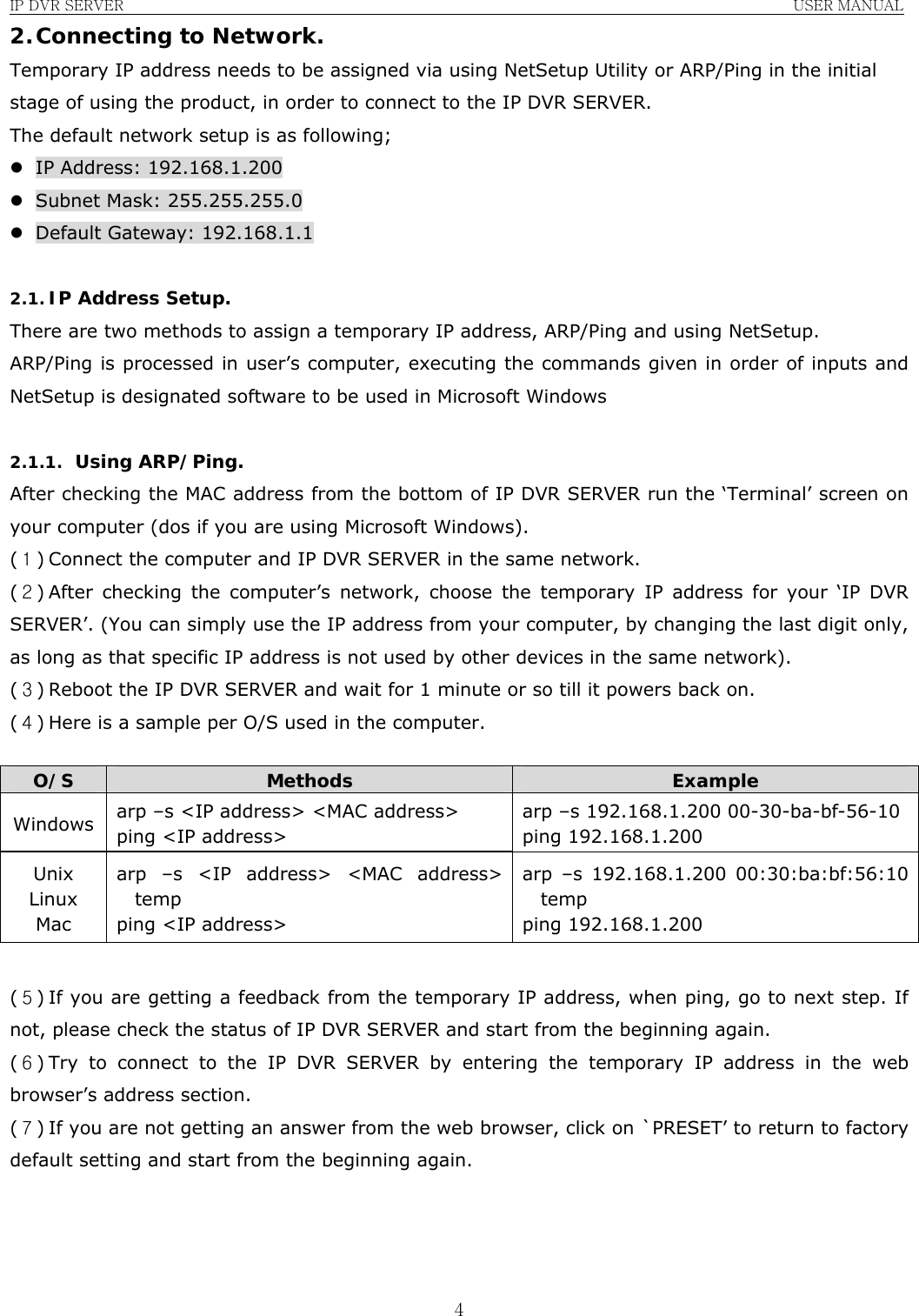
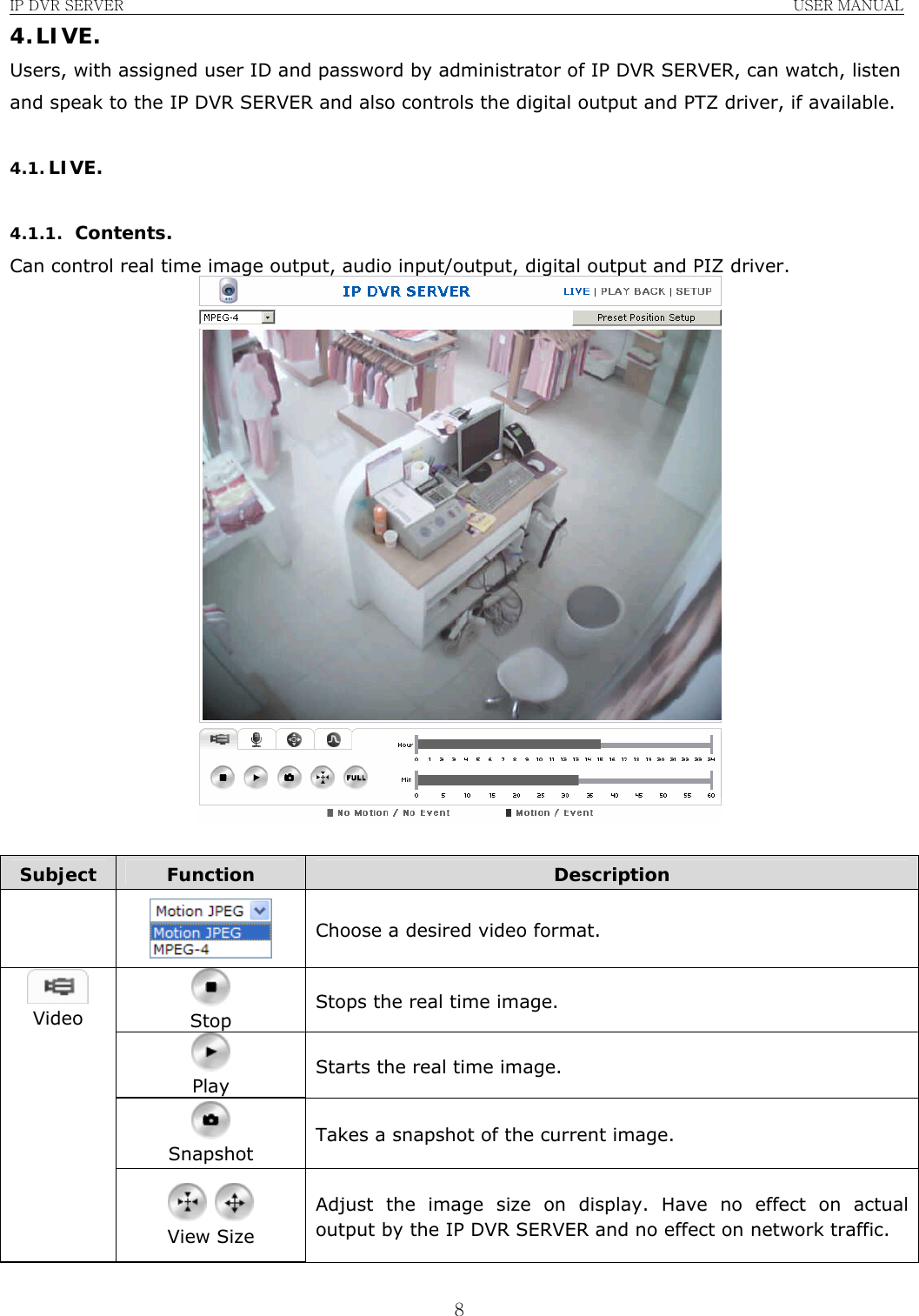
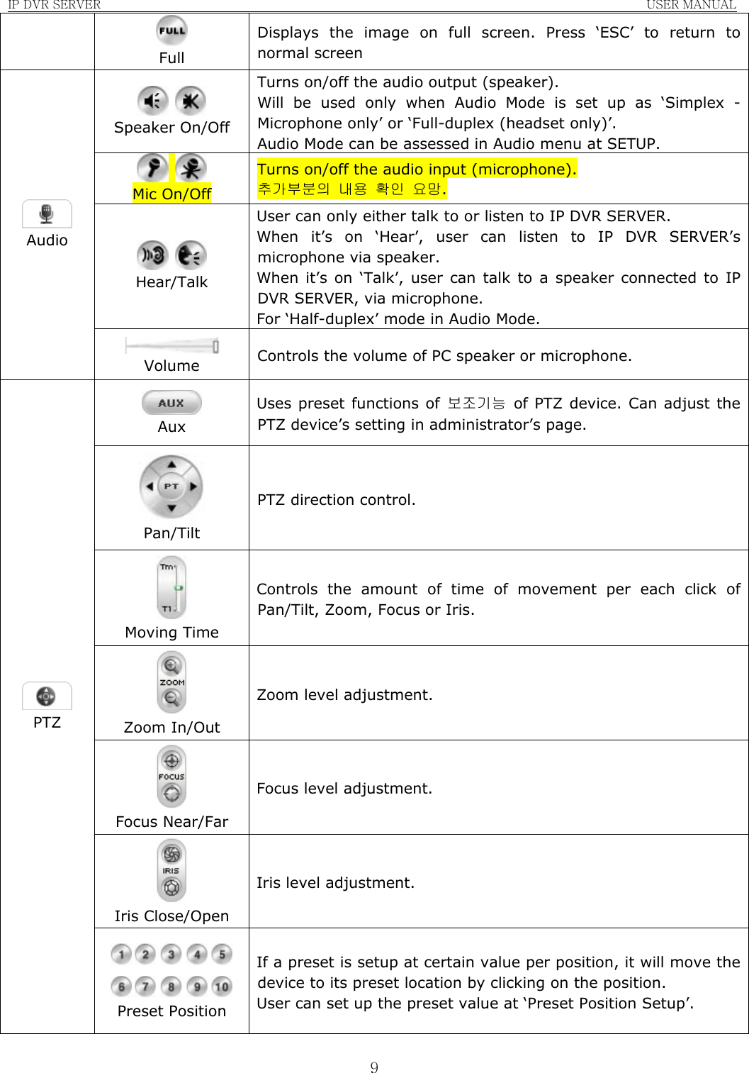
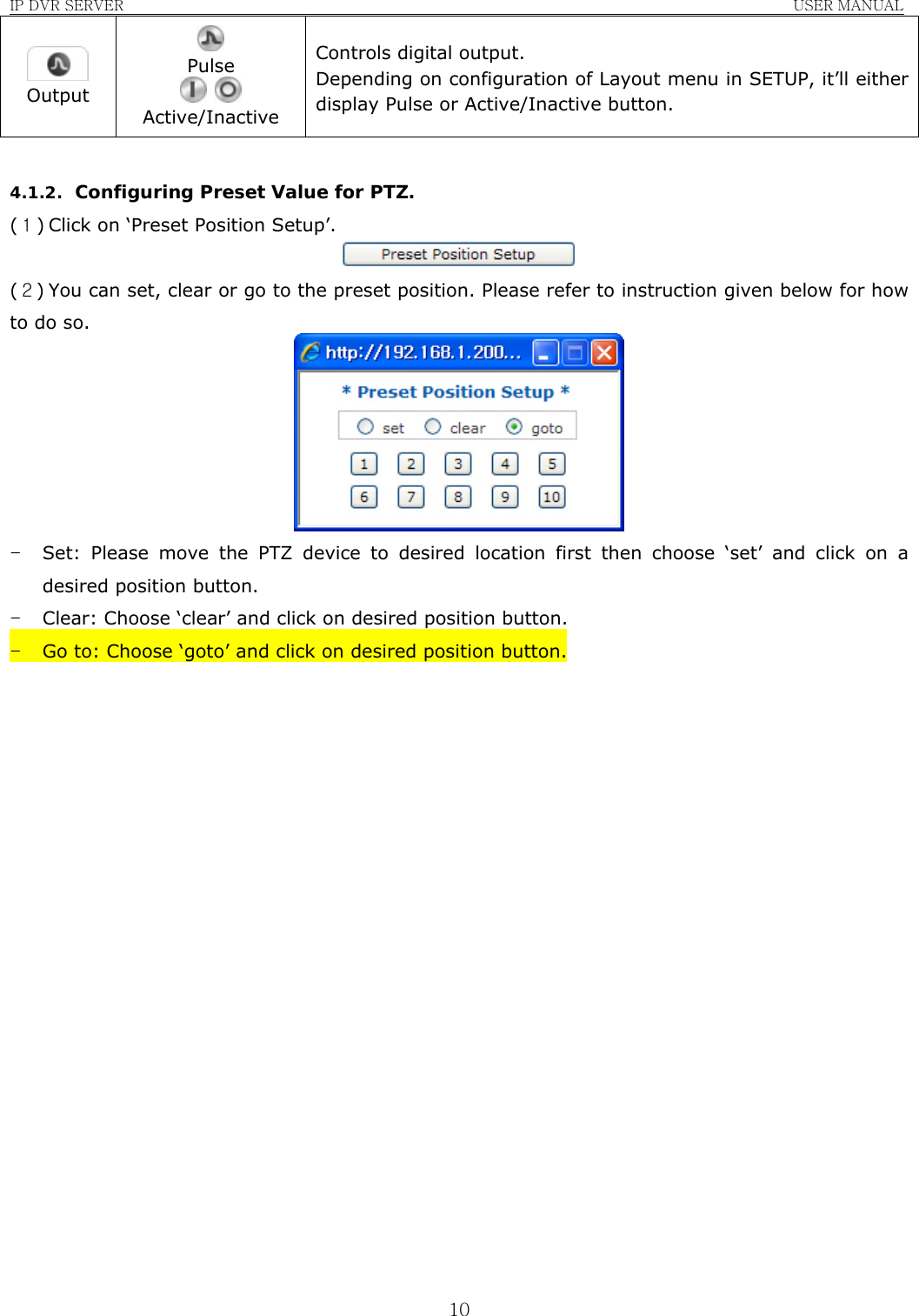

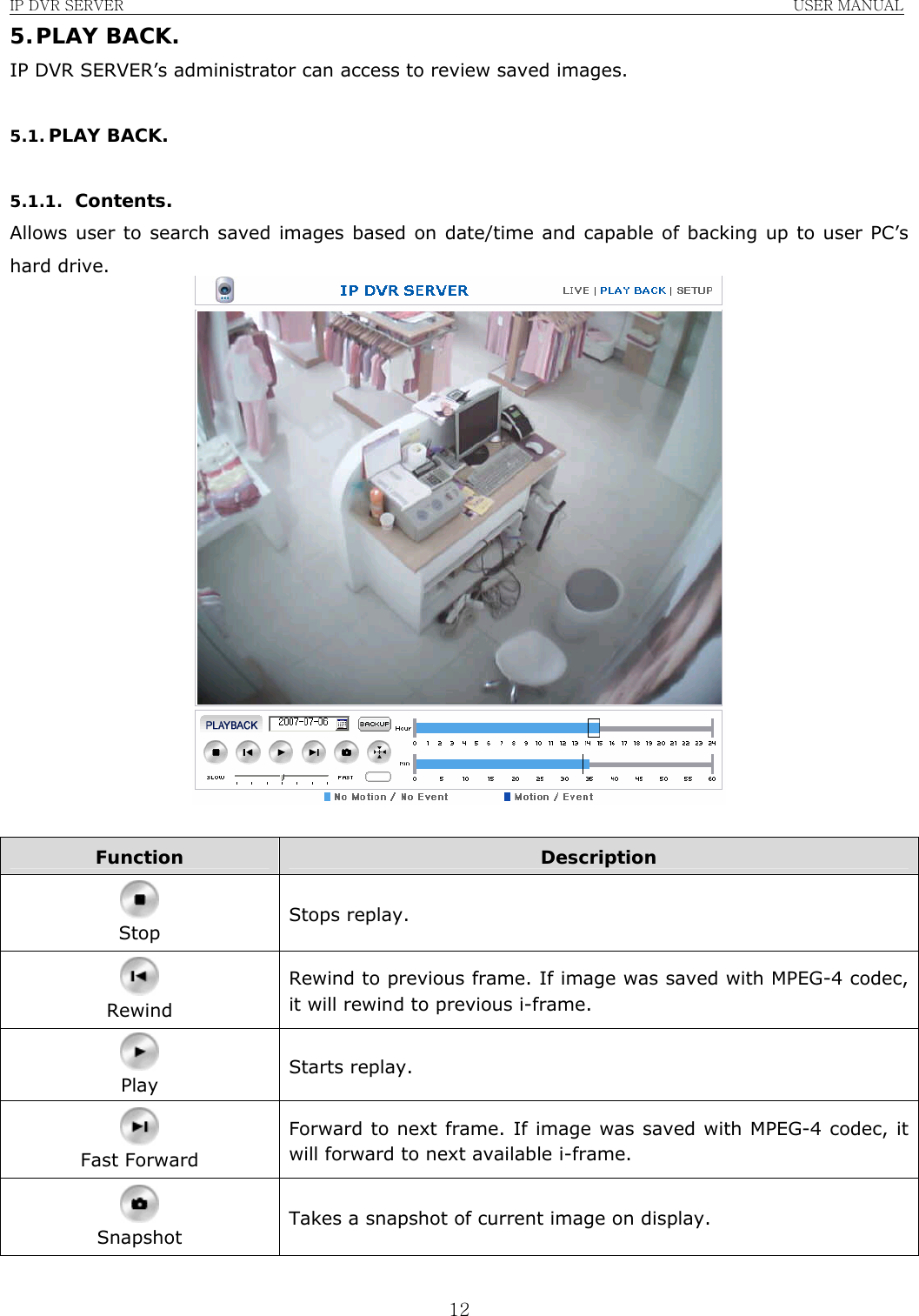
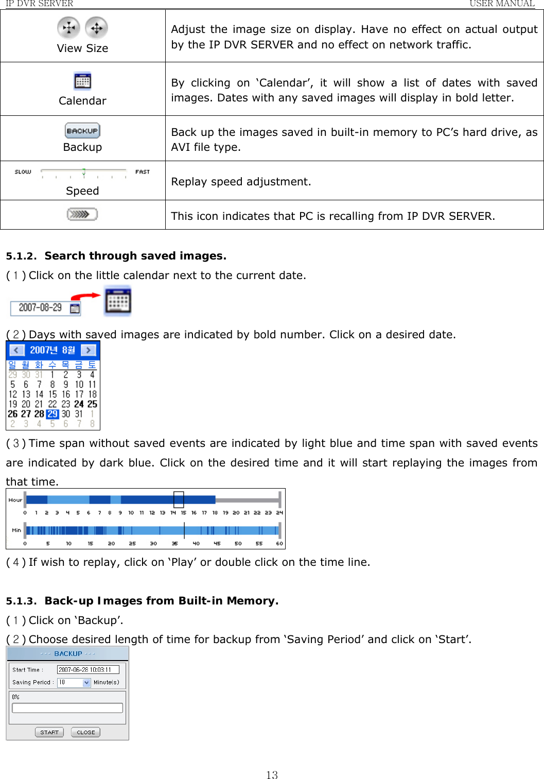
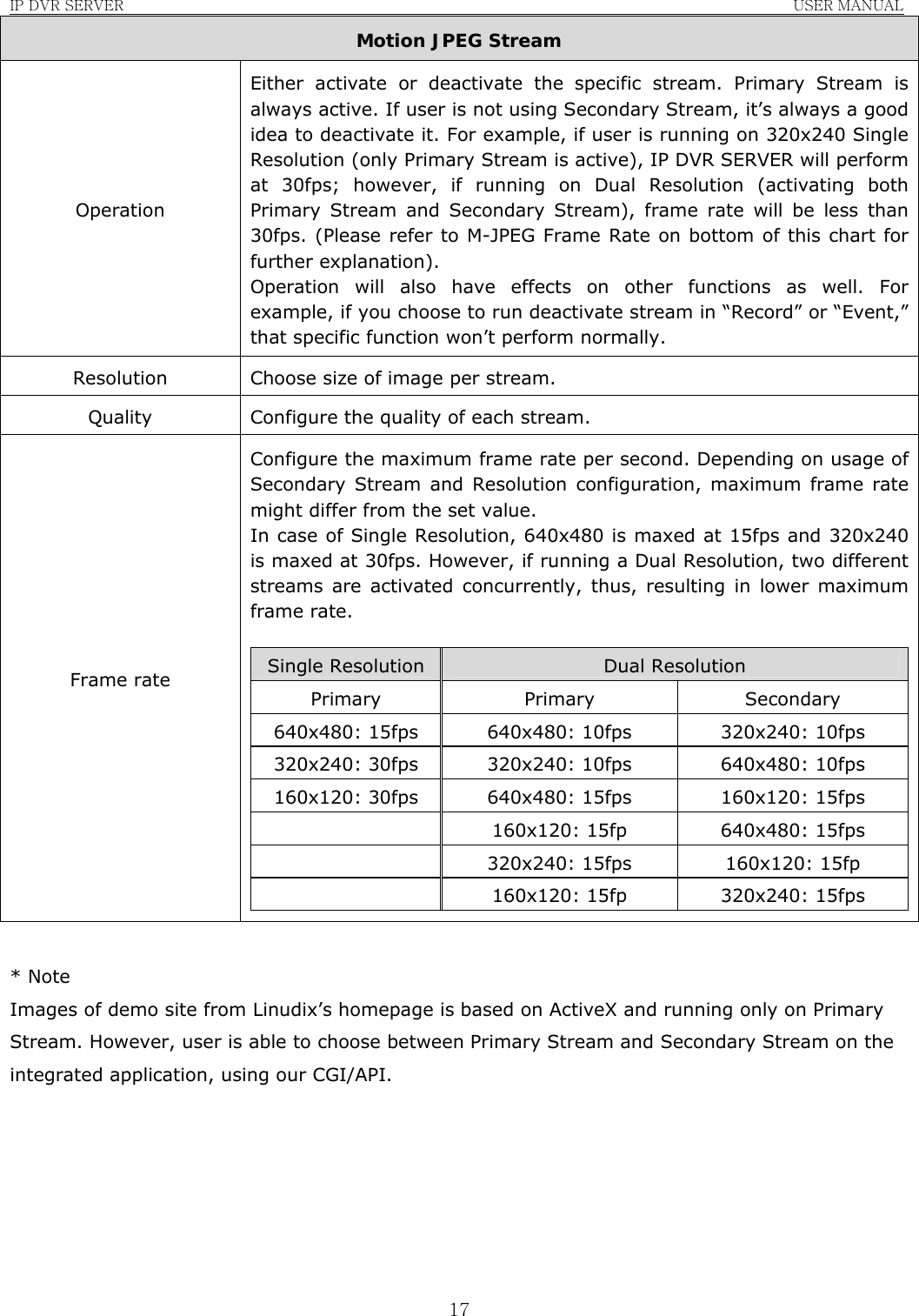
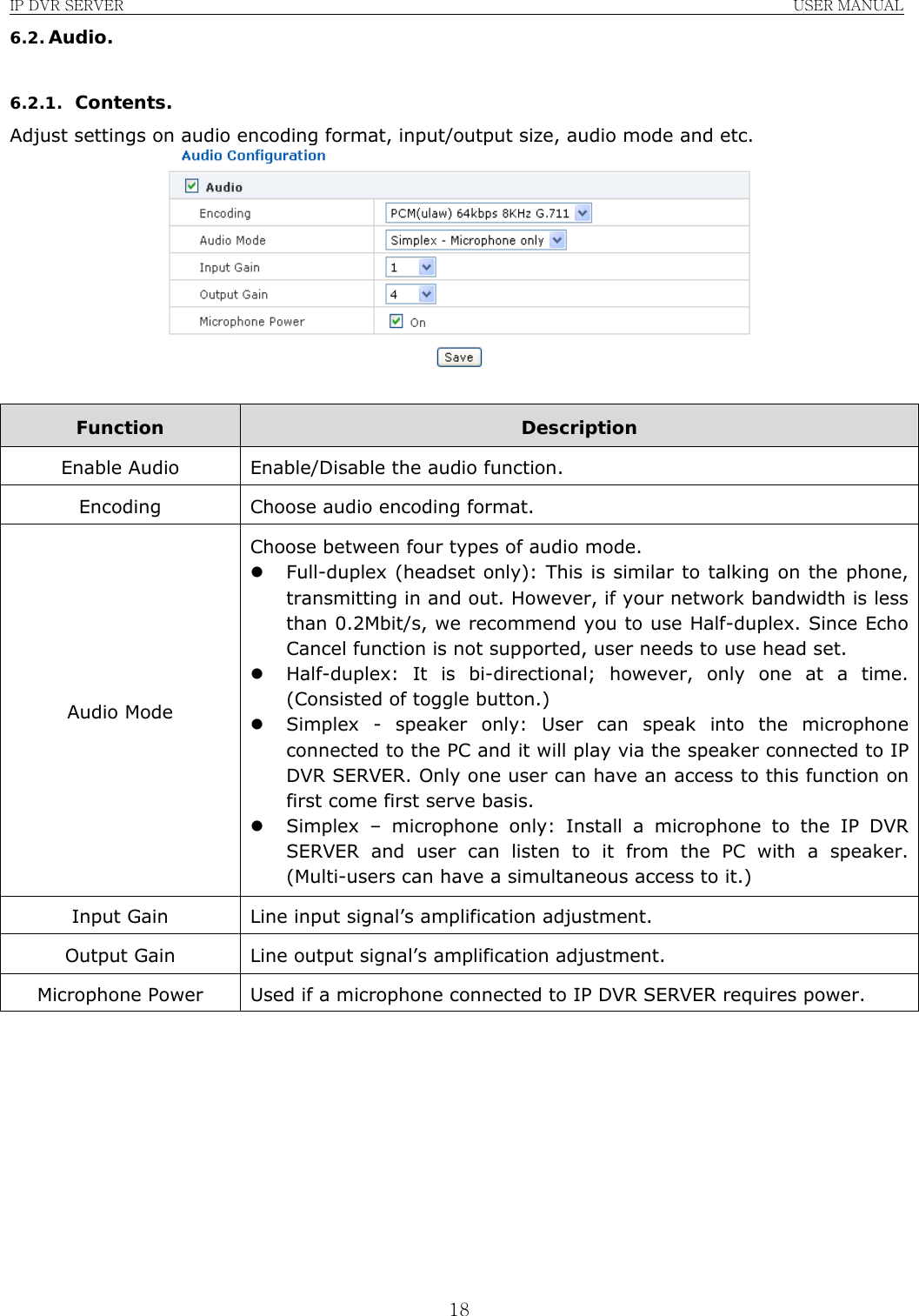
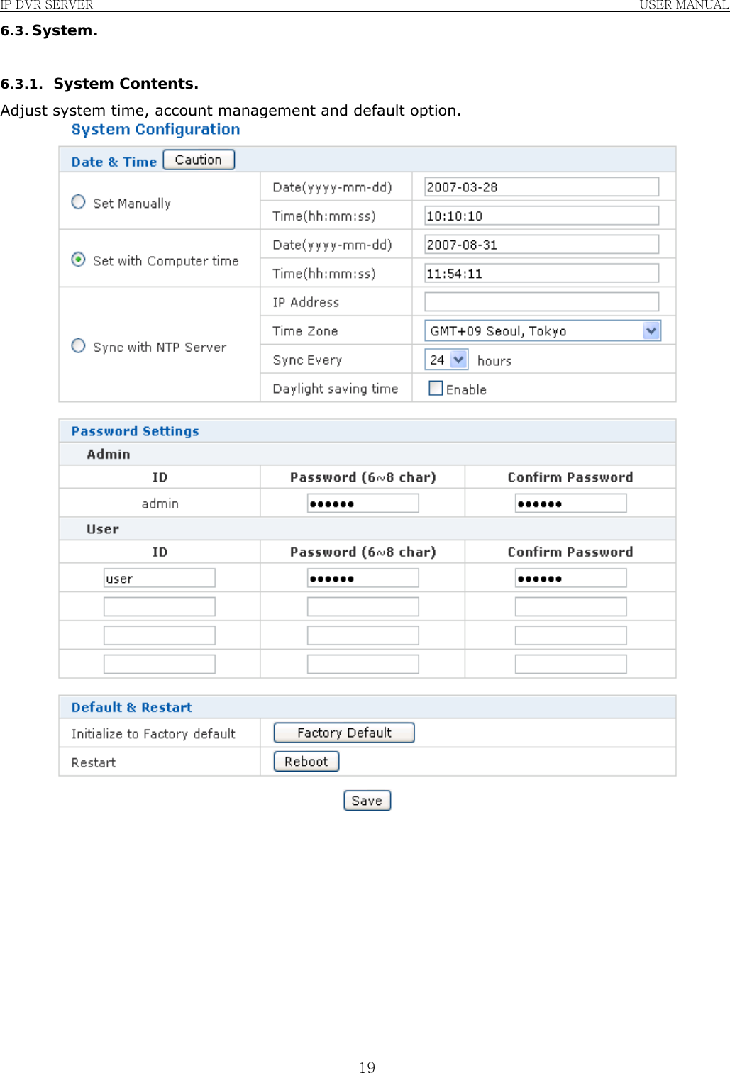
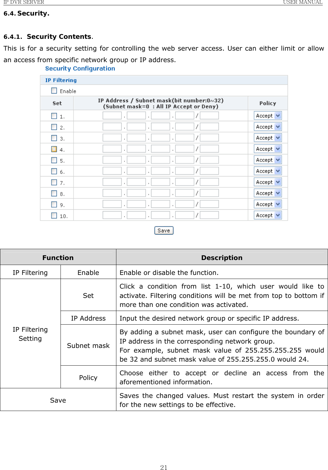
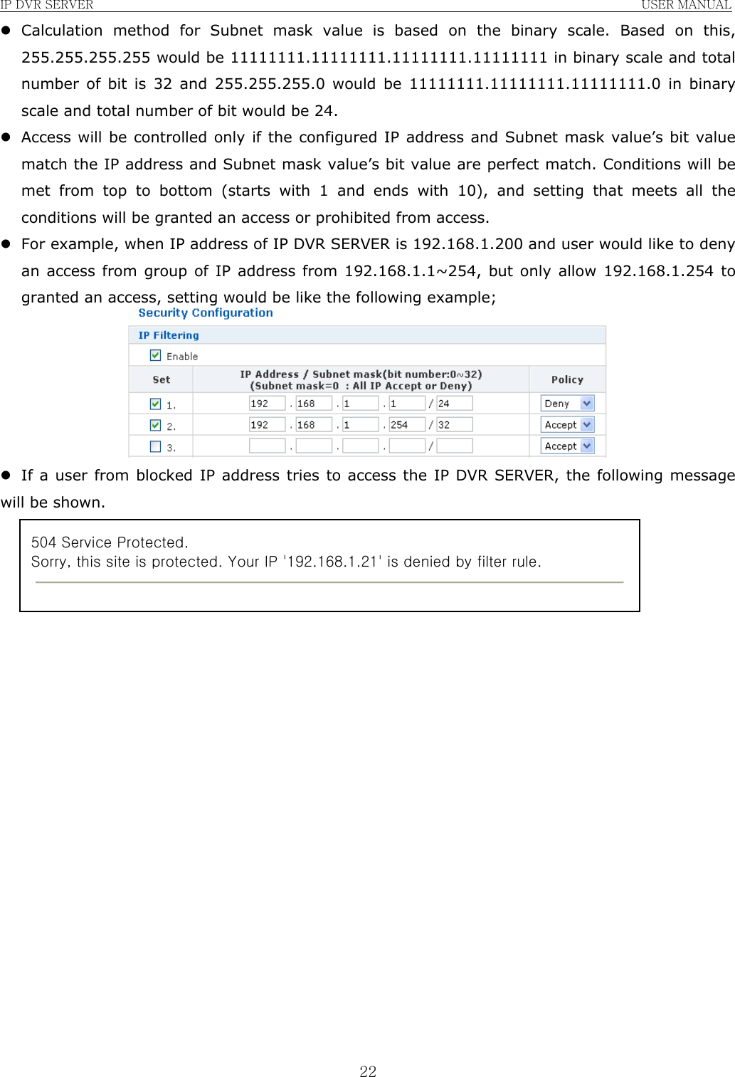
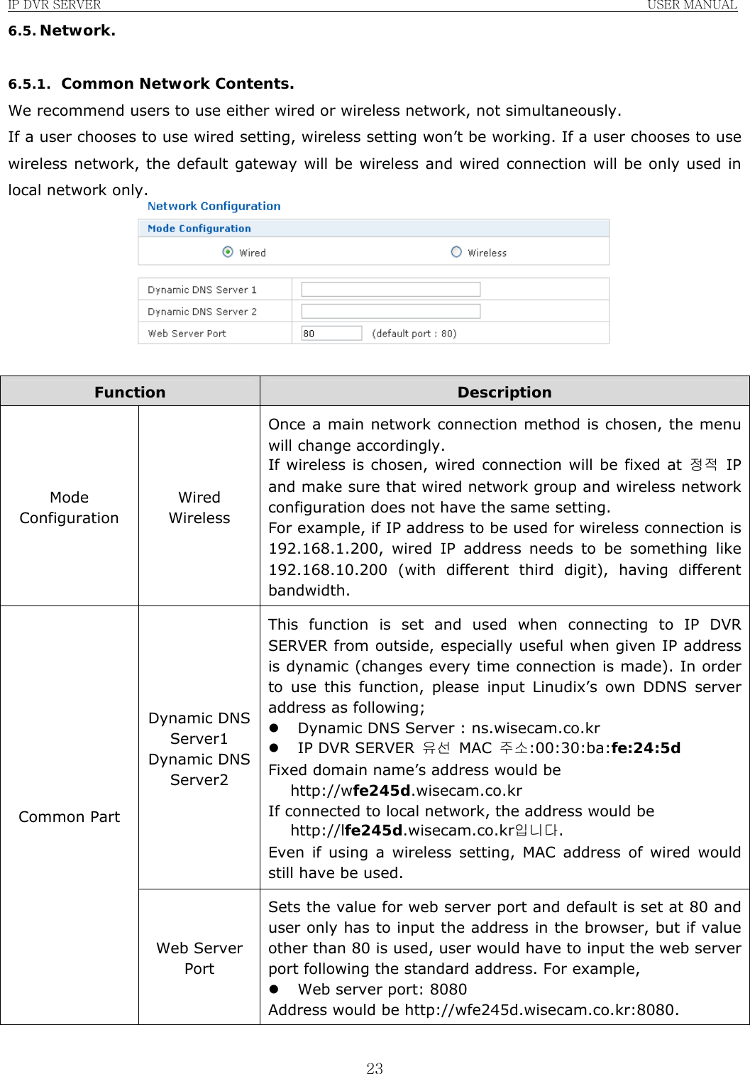
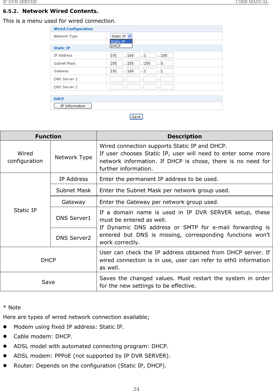
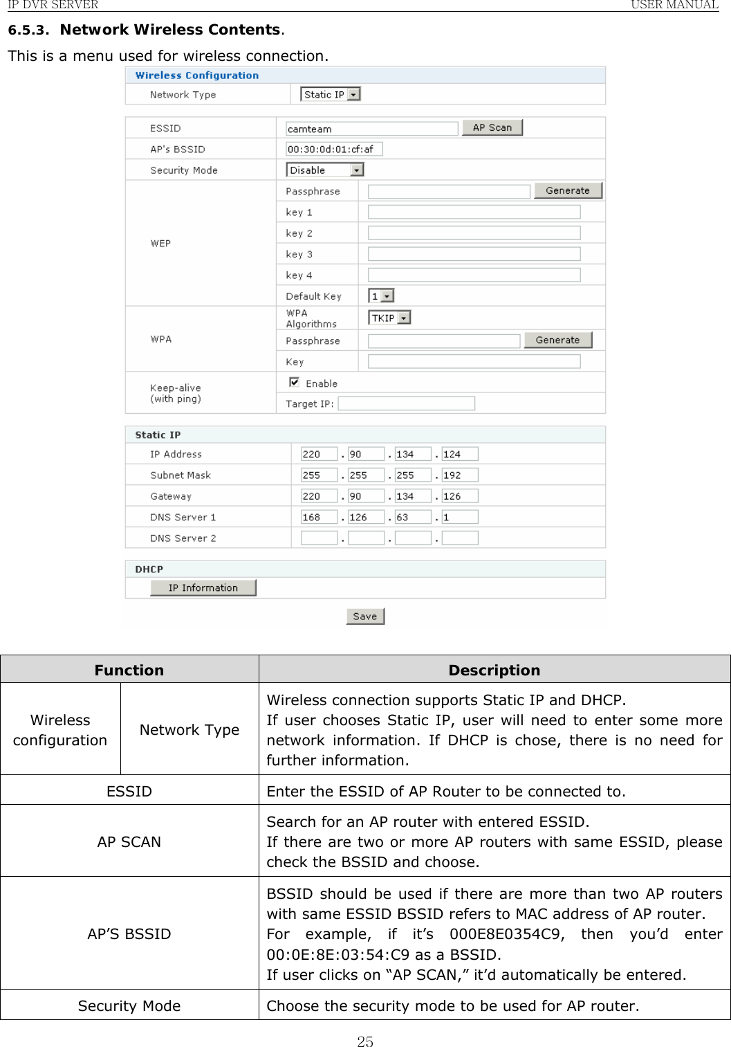
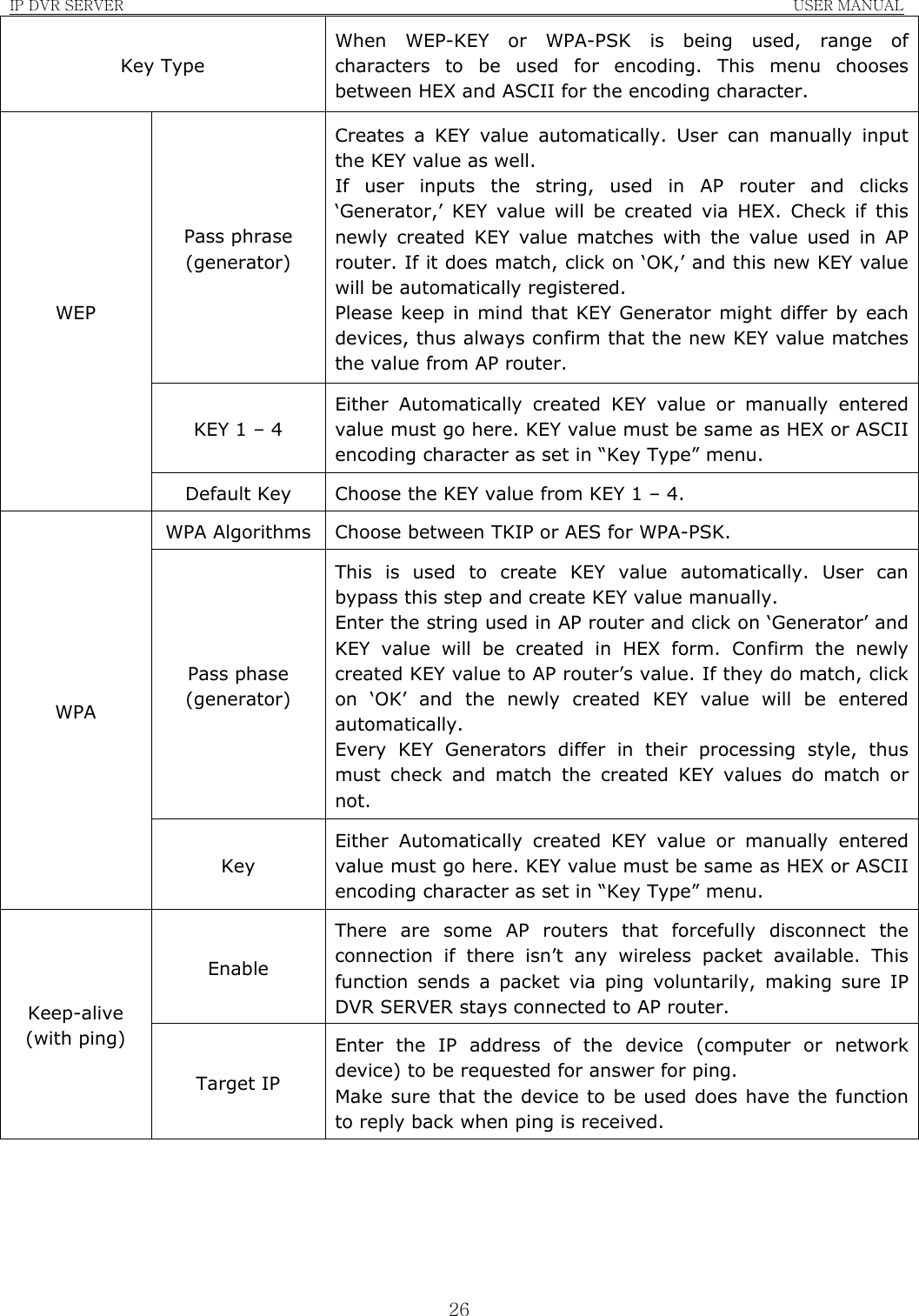
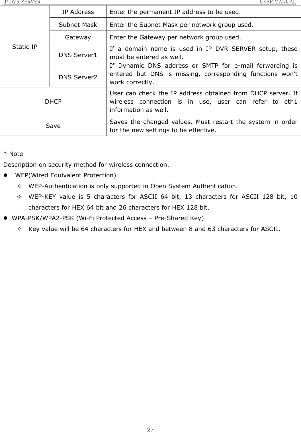
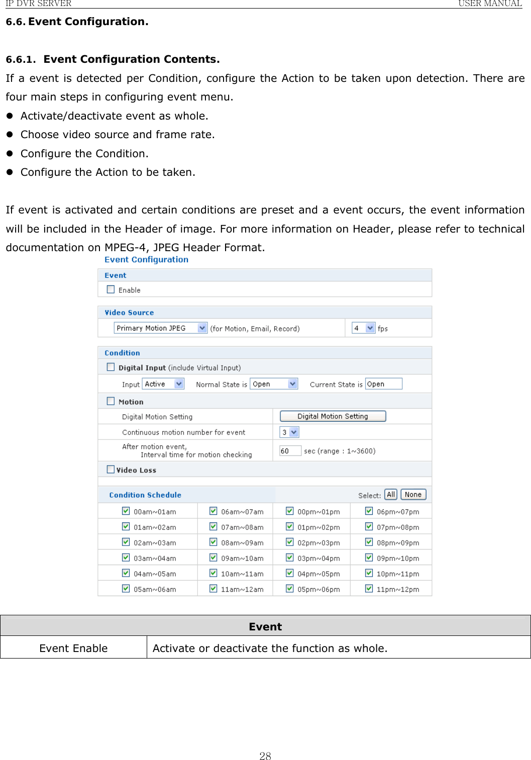
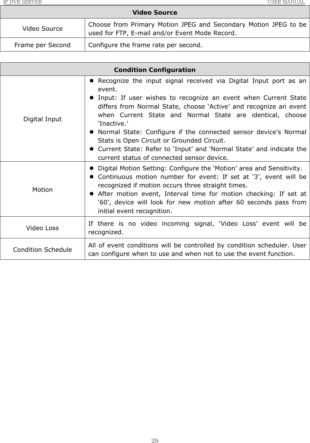
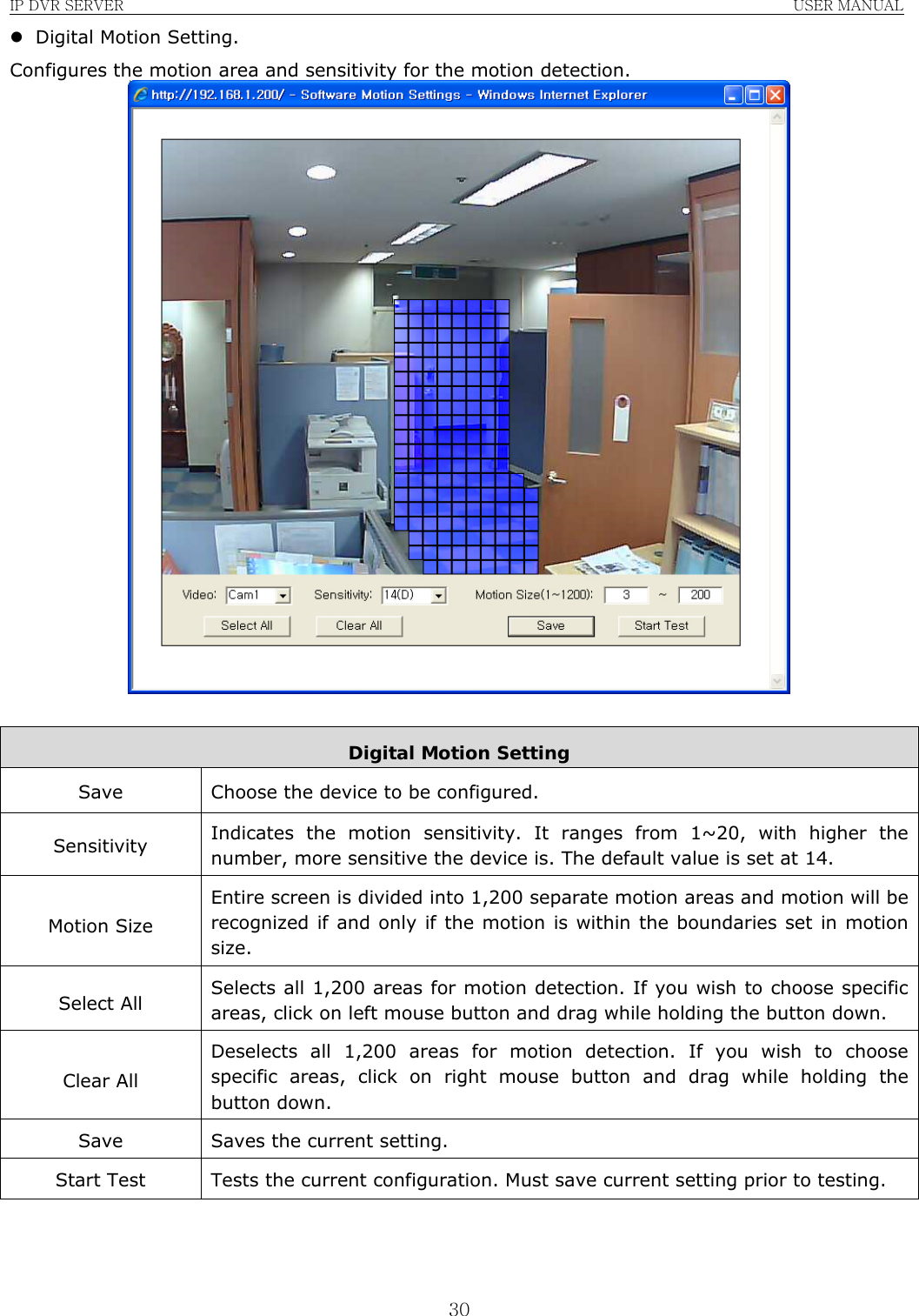
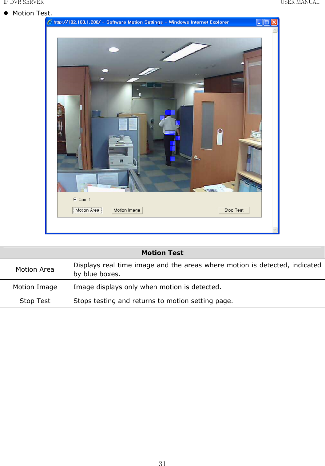
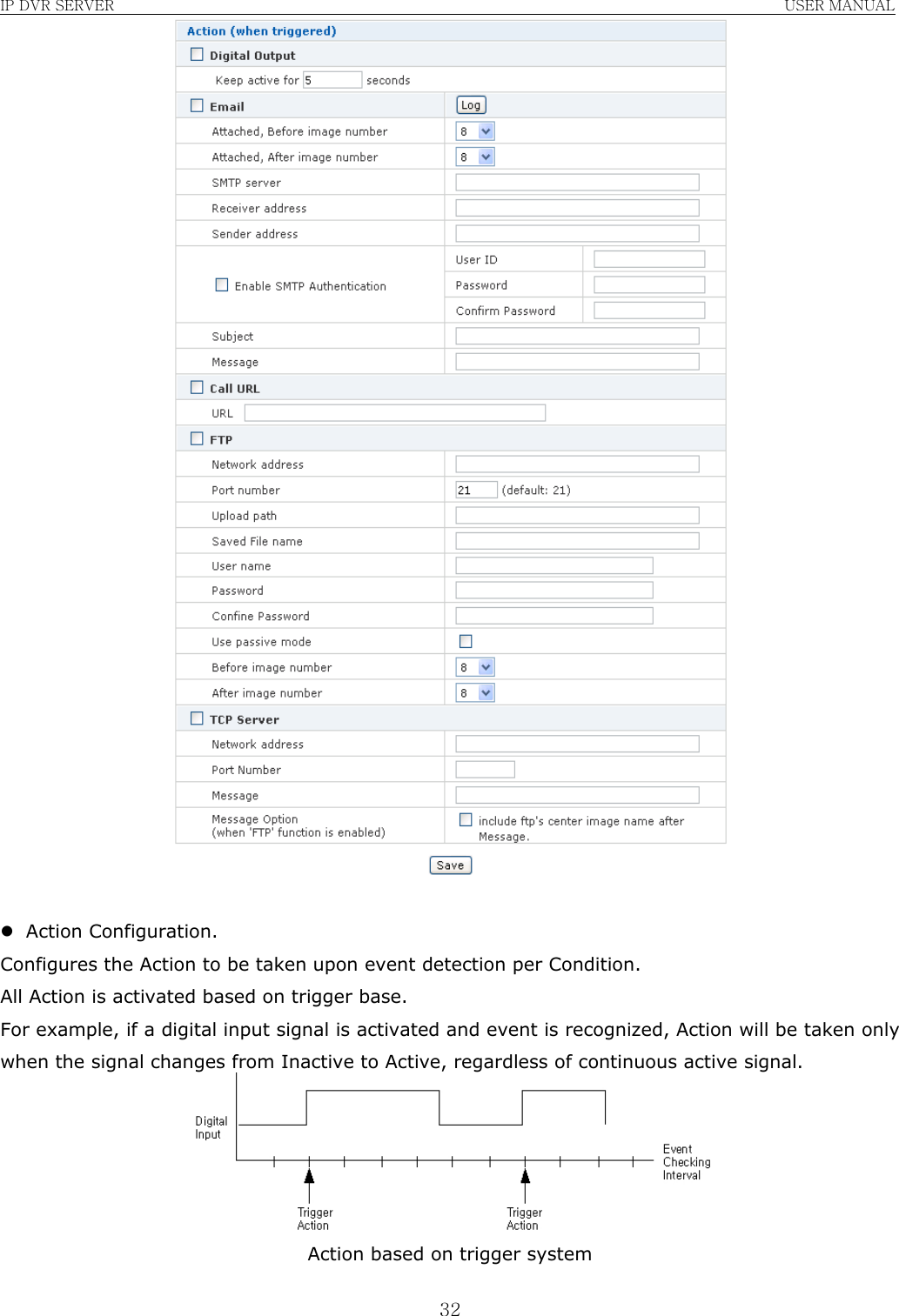
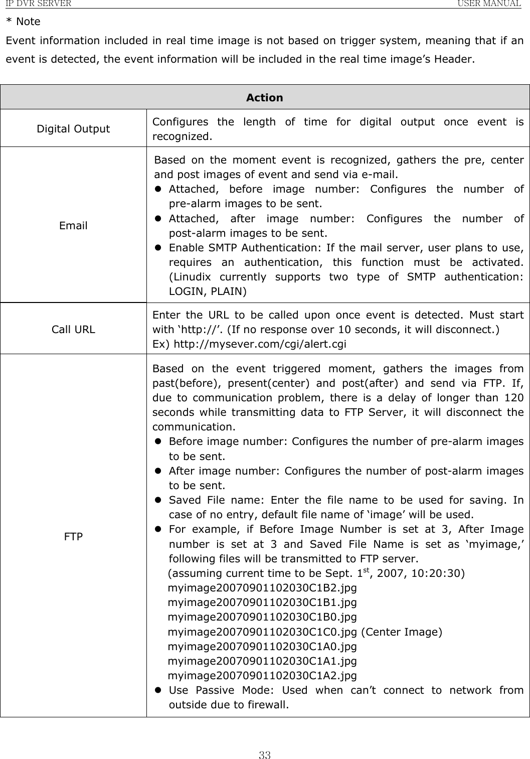
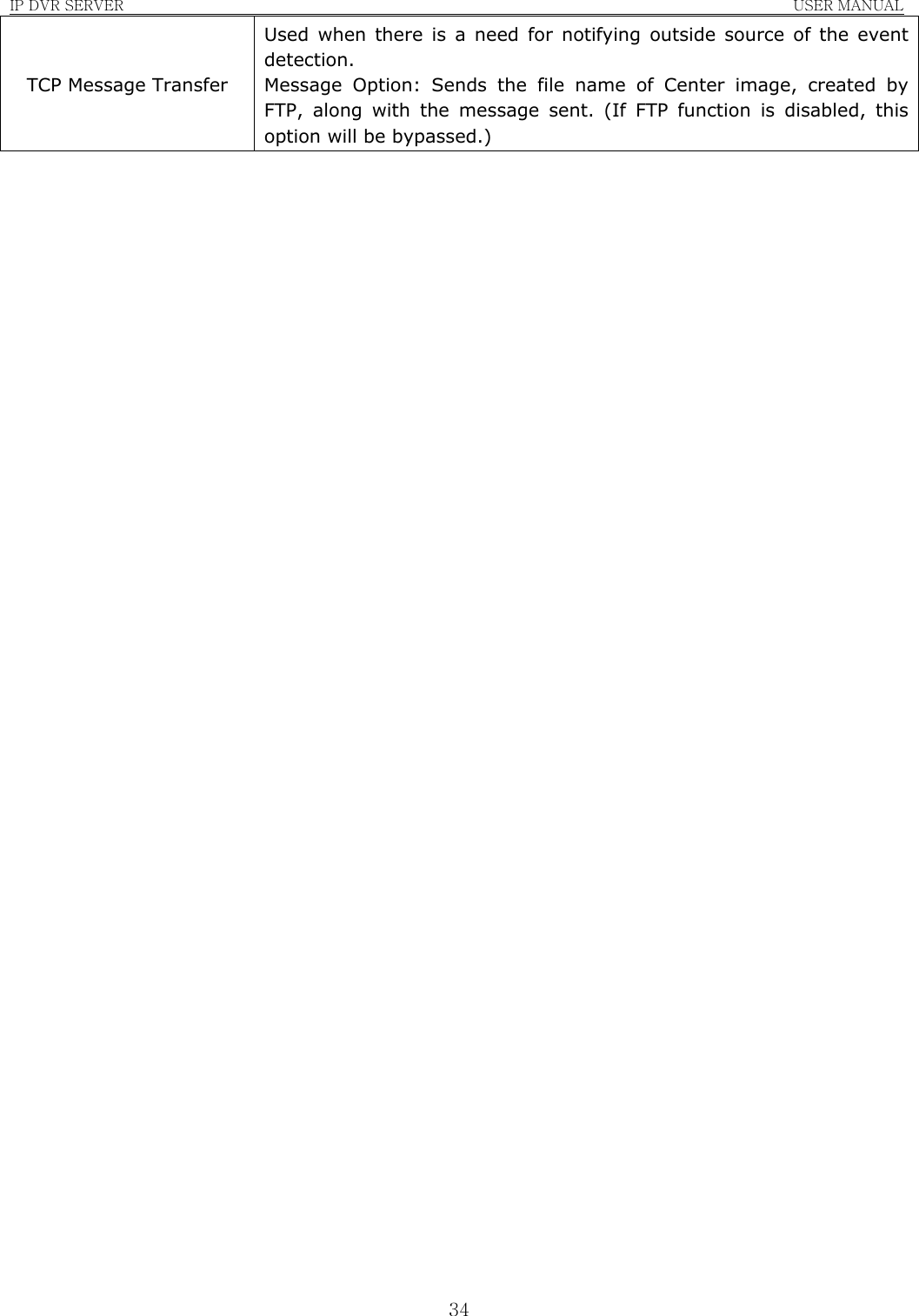
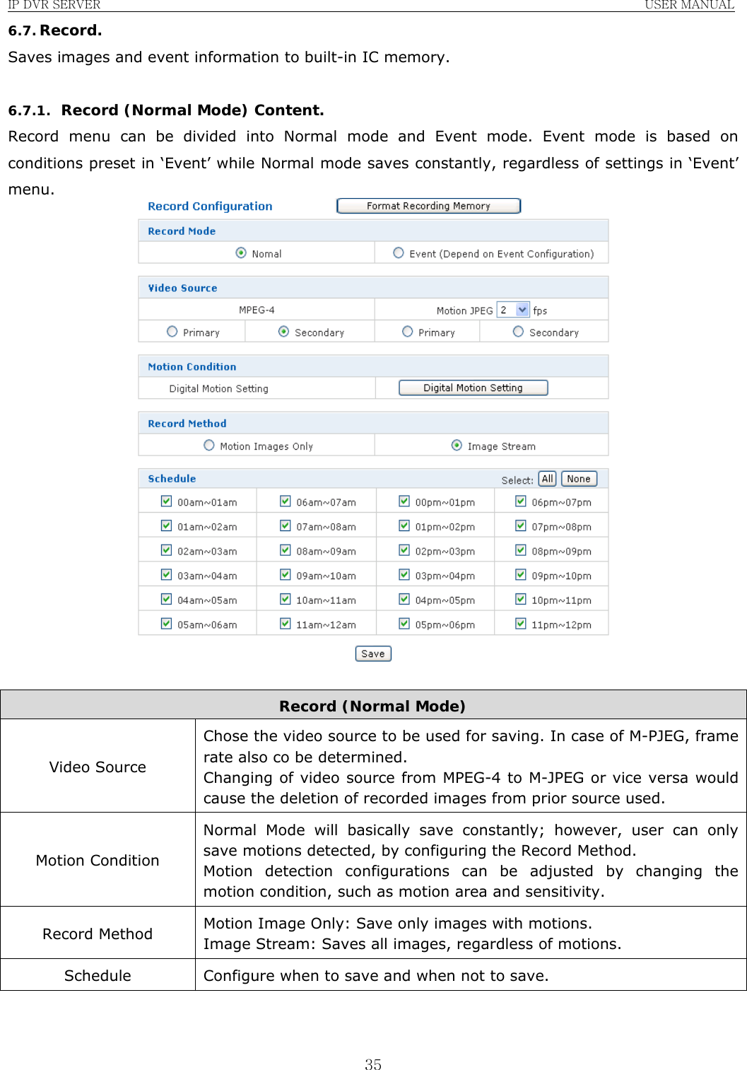
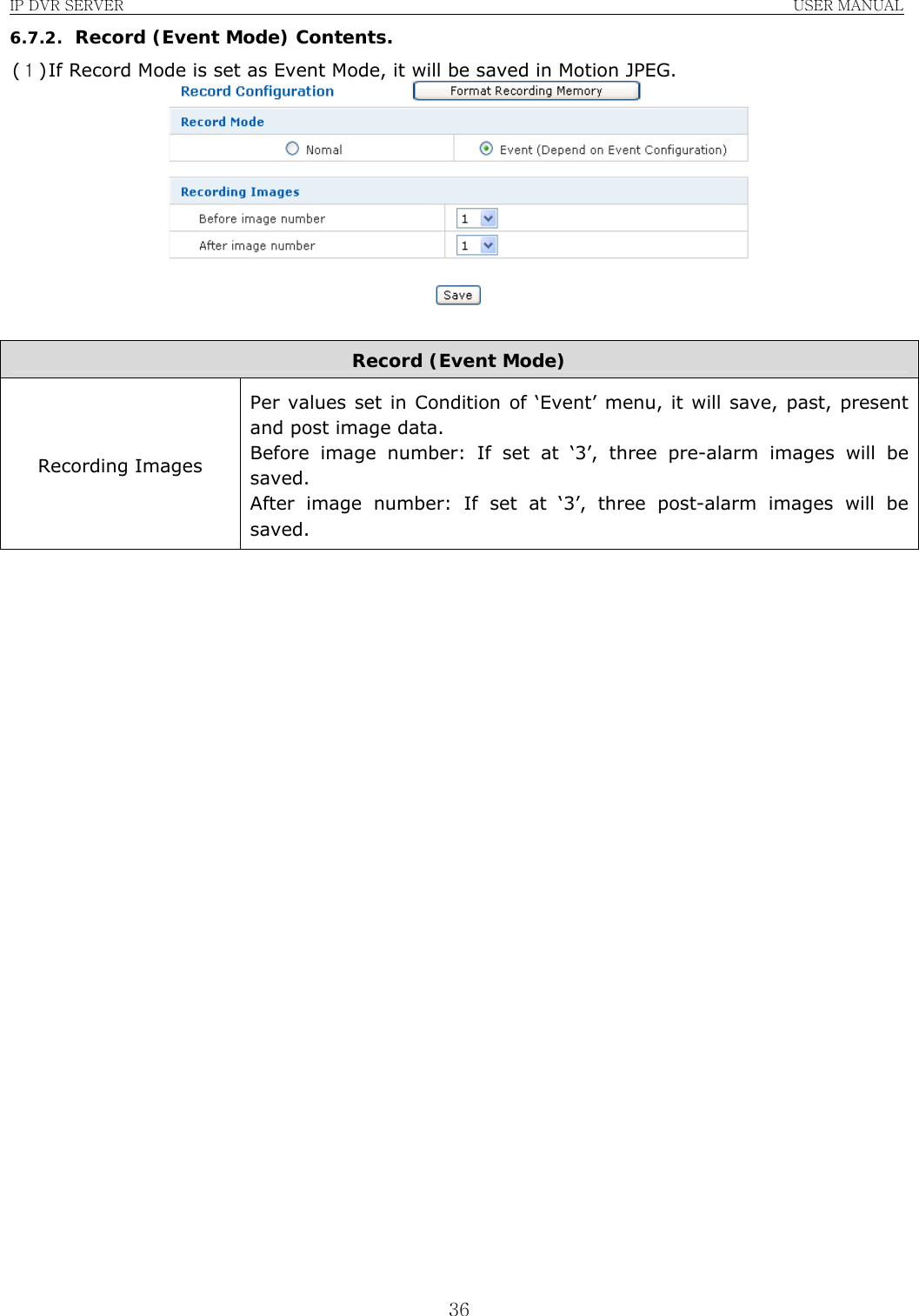
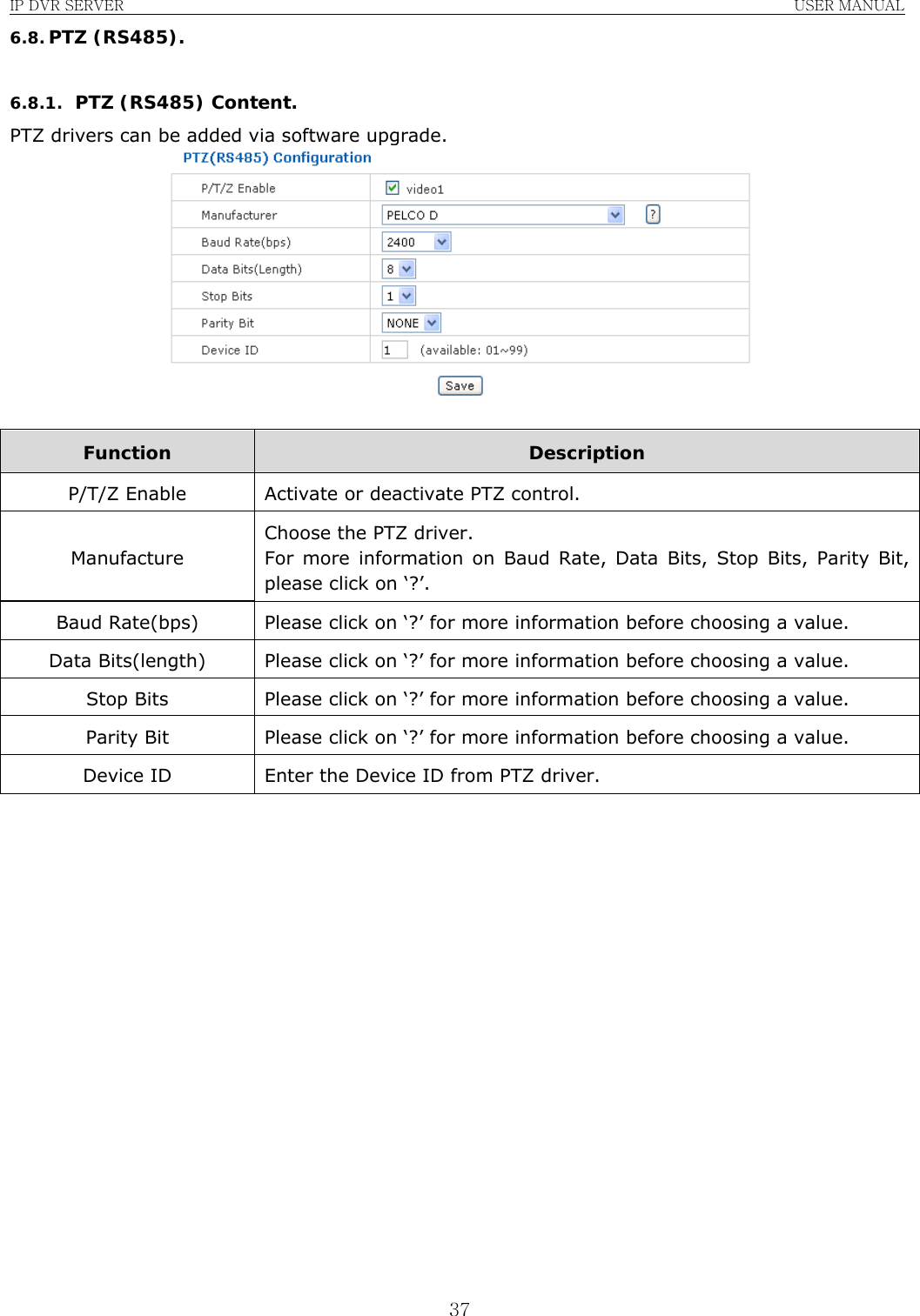
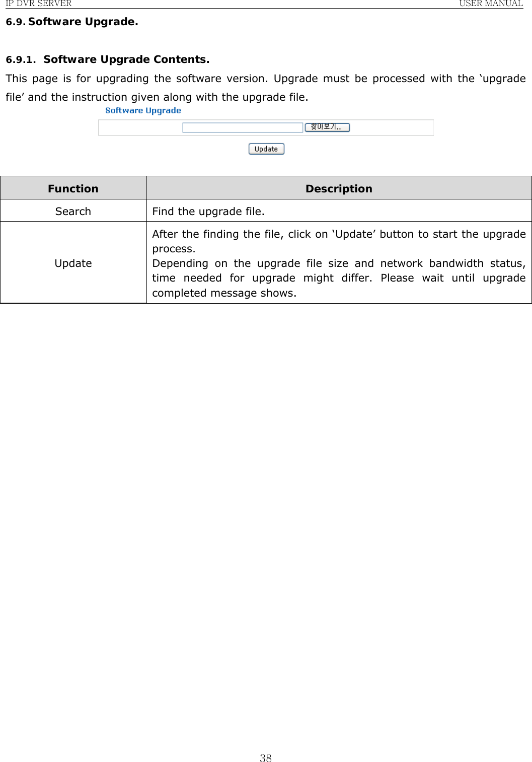
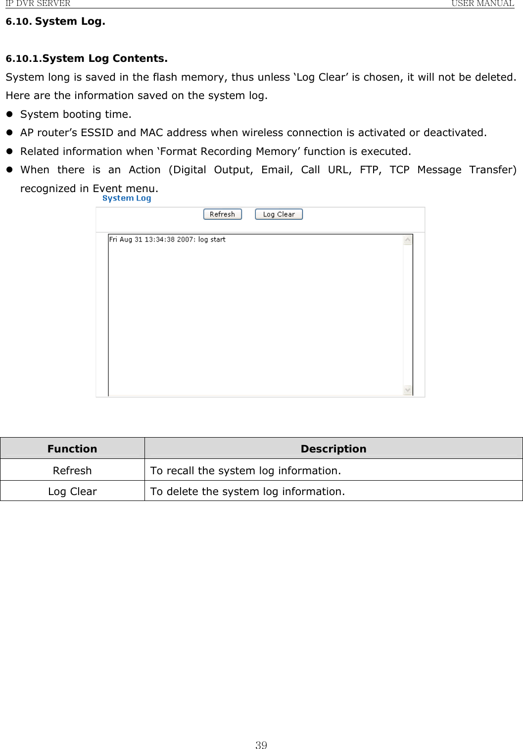
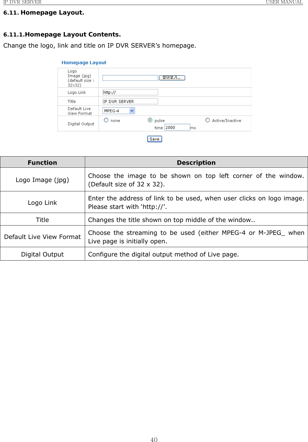
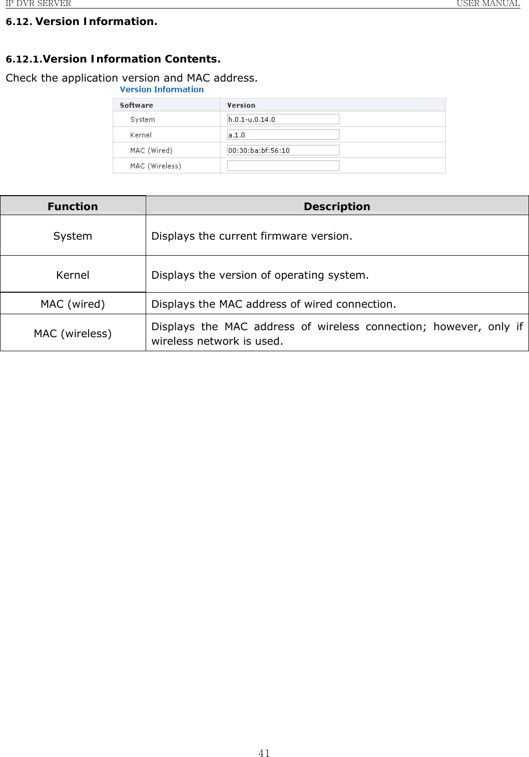
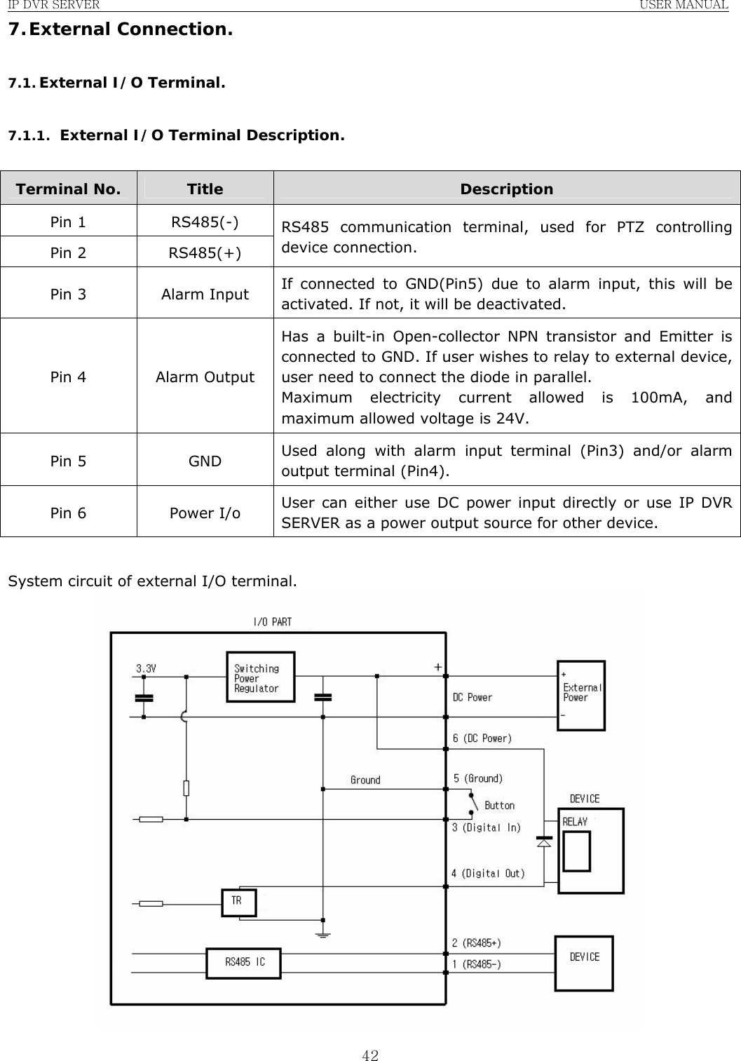
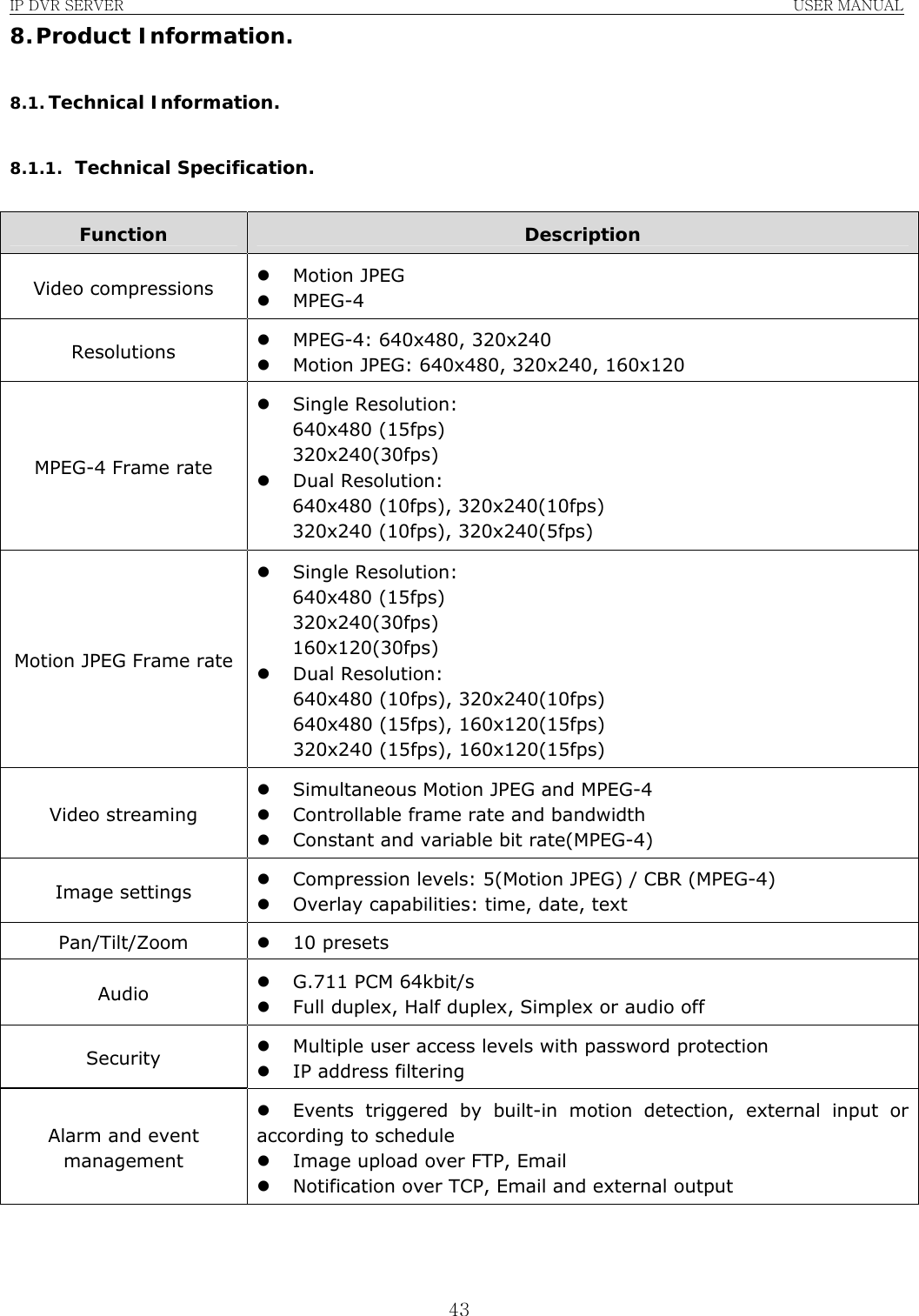
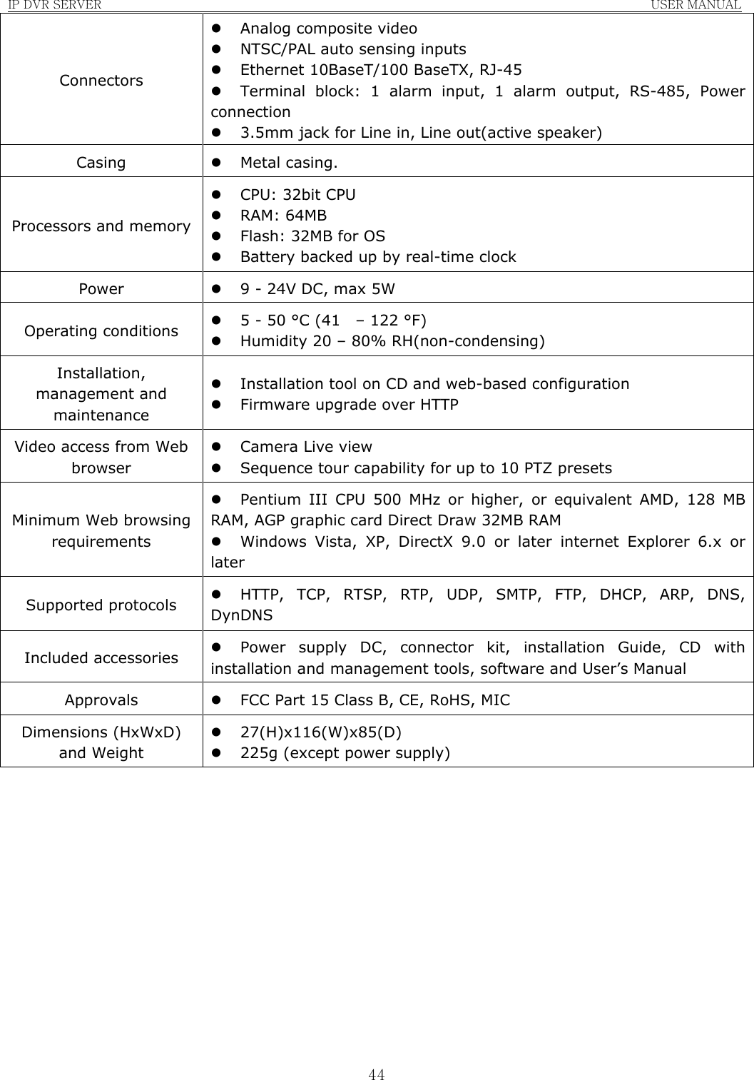
![IP DVR SERVER USER MANUAL 20Function Description Set Manually User manually inputs date and time as a system time. Ex.) When user would like to input 2004/11/01, 13:00. Date(yyyy-mm-dd): 2004-11-01 Time(hh:mm:ss): 13:00:00 Set with Computer time Use user PC’s system time as a system time of IP DVR SERVER. Time Sync with NTP Server Obtain the information from the time server (NTP server) and set as system time. Input the address of time server and reconnection period. Daylight Saving Time: Adjust the time if daylight saving is used in user’s resident country. Password Default ID is [admin] and default password is set as [admin0]. Use can change to desired ID and password. Admin Confirm Password Retype to password to confirm the new password. Initialize Factory default Used when user wishes to return the setting back to factory default. Once executed, IP DVR SERVER must restart; however, network information won’t alter, allowing user to carry out the function from remote location. System Restart Used when user would like to reboot the system. ID If user feels the necessity of limiting the user access, user can register more user IDs, up to four different accounts. Password Input a password per extra user ID created. User Confirm Password Retype the password to confirm the new password.](https://usermanual.wiki/Linudix/LWS110F/User-Guide-919438-Page-20.png)