Linx Technologies 3F090012X Wi.232 Transmitter User Manual WiUSB DTS User s Manual rev D
Linx Technologies Wi.232 Transmitter WiUSB DTS User s Manual rev D
UserManual.wiki
>
Linx Technologies
>
3F090012X User Manual
>
User Manual
Contents
1.
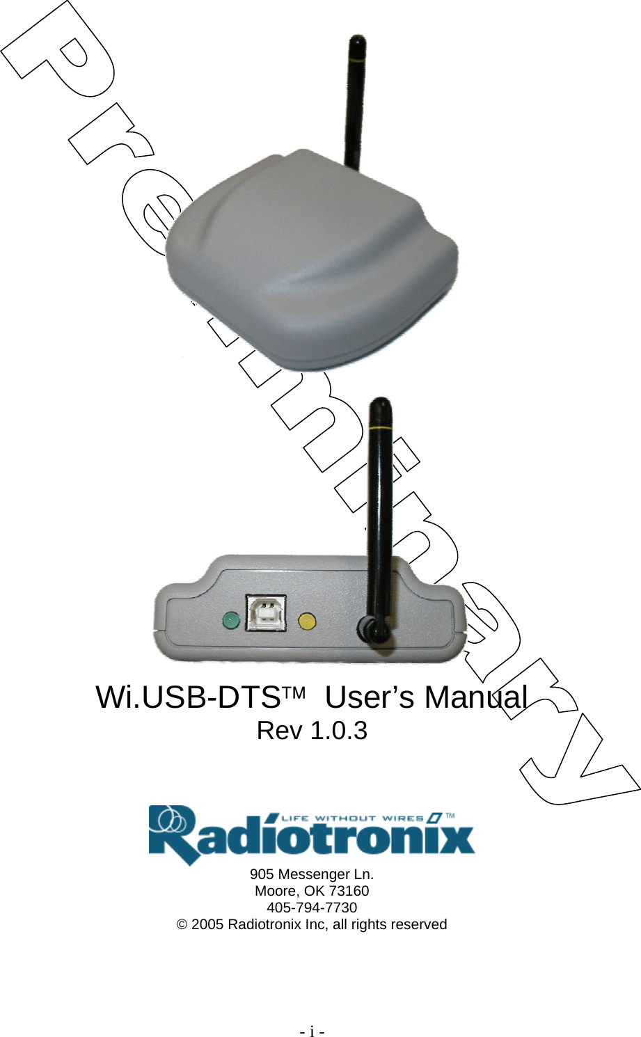
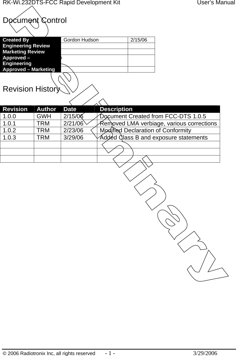
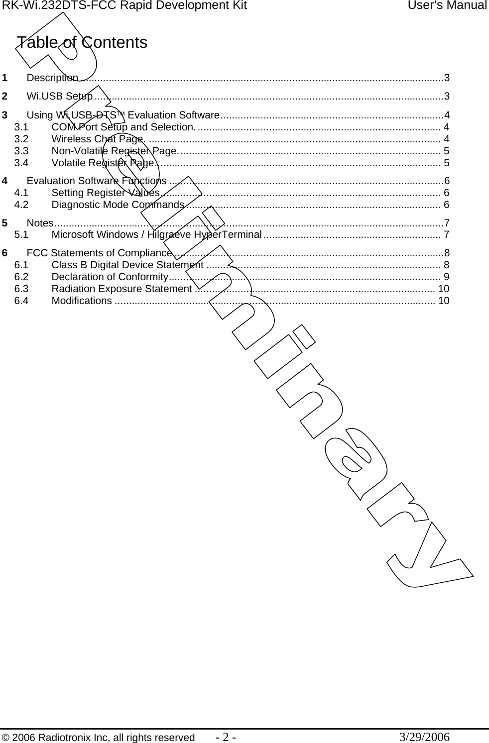
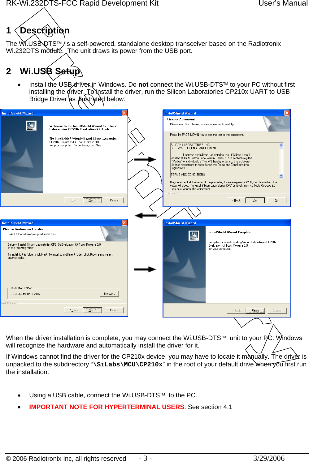
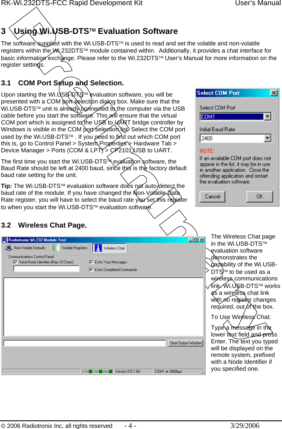
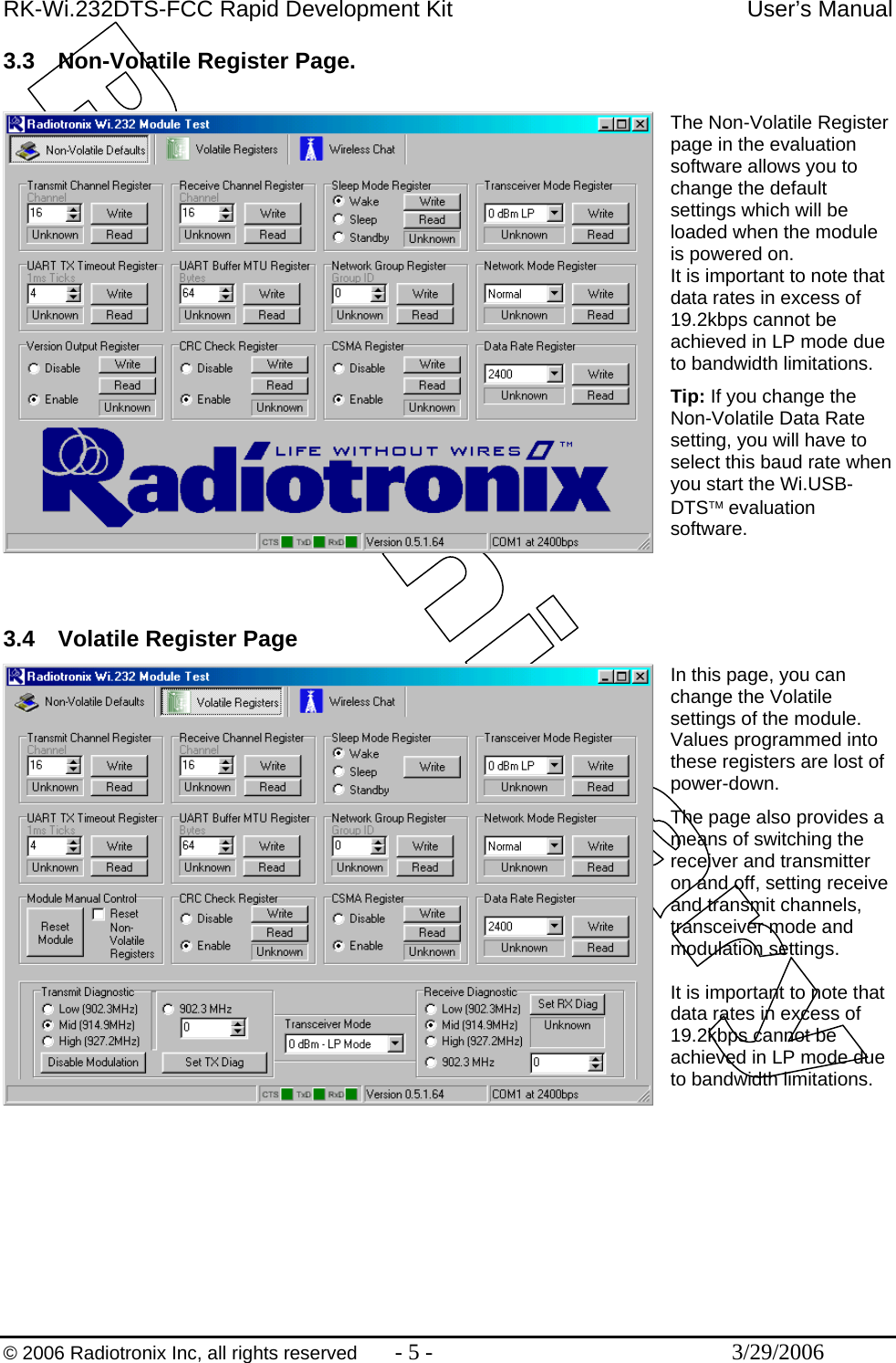
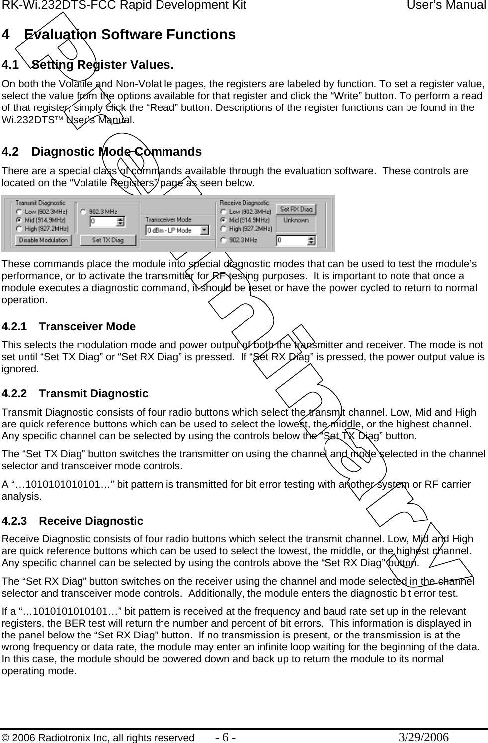
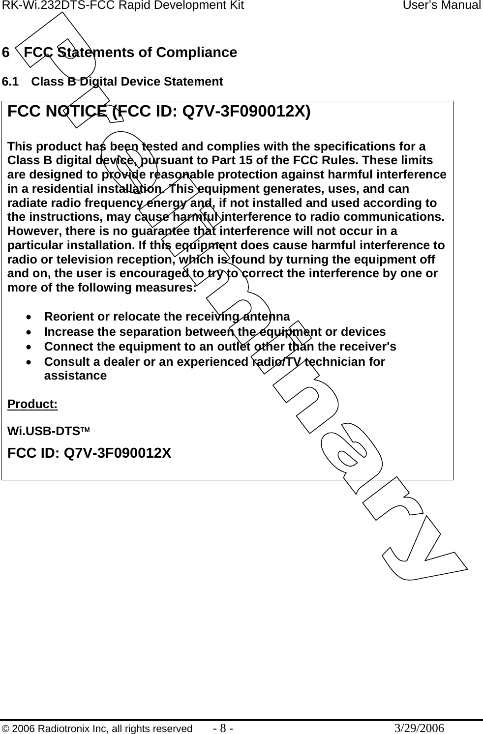
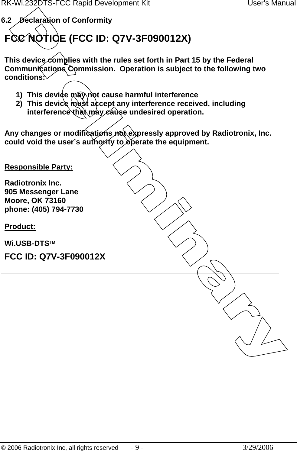
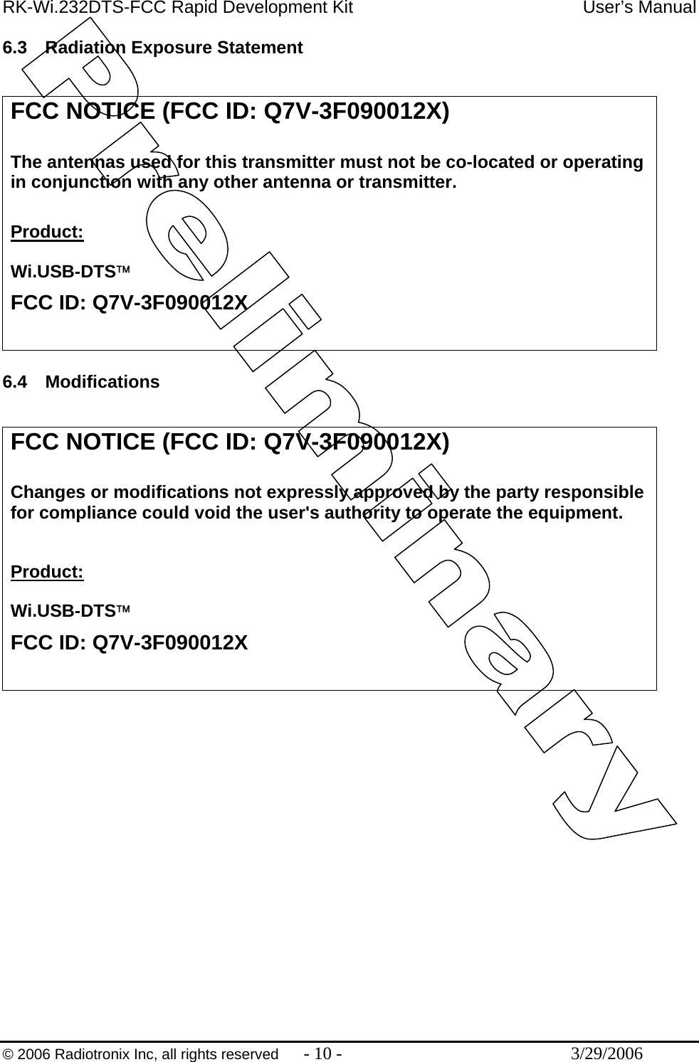
User Manual
2.
Users Manual DoC
User Manual
Navigation menu
Upload a User Manual
Namespaces
Wiki Guide
HTML
PDF
Info
Views
User Manual
Discussion / Help
Navigation