Linx Technologies 3F090012X Wi.232 Transmitter User Manual WiUSB DTS User s Manual rev D
Linx Technologies Wi.232 Transmitter WiUSB DTS User s Manual rev D
Contents
- 1. User Manual
- 2. Users Manual DoC
User Manual
- i -
Wi.USB-DTS™ User’s Manual
Rev 1.0.3
905 Messenger Ln.
Moore, OK 73160
405-794-7730
© 2005 Radiotronix Inc, all rights reserved

RK-Wi.232DTS-FCC Rapid Development Kit User’s Manual
© 2006 Radiotronix Inc, all rights reserved - 1 - 3/29/2006
Document Control
Created By Gordon Hudson 2/15/06
Engineering Review
Marketing Review
Approved –
Engineering
Approved – Marketing
Revision History
Revision Author Date Description
1.0.0 GWH 2/15/06 Document Created from FCC-DTS 1.0.5
1.0.1 TRM 2/21/06 Removed LMA verbiage, various corrections
1.0.2 TRM 2/23/06 Modified Declaration of Conformity
1.0.3 TRM 3/29/06 Added Class B and exposure statements

RK-Wi.232DTS-FCC Rapid Development Kit User’s Manual
© 2006 Radiotronix Inc, all rights reserved - 2 - 3/29/2006
Table of Contents
1 Description ...............................................................................................................................3
2 Wi.USB Setup..........................................................................................................................3
3 Using Wi.USB-DTS™ Evaluation Software..............................................................................4
3.1 COM Port Setup and Selection...................................................................................... 4
3.2 Wireless Chat Page. ...................................................................................................... 4
3.3 Non-Volatile Register Page............................................................................................ 5
3.4 Volatile Register Page.................................................................................................... 5
4 Evaluation Software Functions ................................................................................................6
4.1 Setting Register Values.................................................................................................. 6
4.2 Diagnostic Mode Commands......................................................................................... 6
5 Notes........................................................................................................................................7
5.1 Microsoft Windows / Hilgraeve HyperTerminal.............................................................. 7
6 FCC Statements of Compliance ..............................................................................................8
6.1 Class B Digital Device Statement .................................................................................. 8
6.2 Declaration of Conformity............................................................................................... 9
6.3 Radiation Exposure Statement .................................................................................... 10
6.4 Modifications ................................................................................................................ 10
RK-Wi.232DTS-FCC Rapid Development Kit User’s Manual
© 2006 Radiotronix Inc, all rights reserved - 3 - 3/29/2006
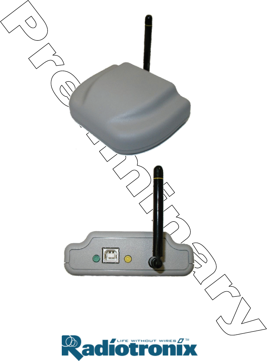
1 Description
The Wi.USB-DTS™ is a self-powered, standalone desktop transceiver based on the Radiotronix
Wi.232DTS module. The unit draws its power from the USB port.
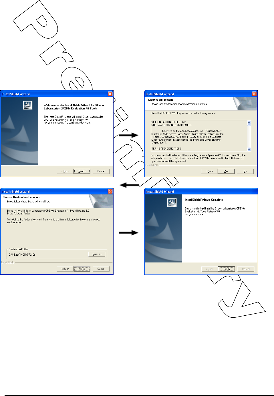
2 Wi.USB Setup
• Install the USB driver in Windows. Do not connect the Wi.USB-DTS™ to your PC without first
installing the driver. To install the driver, run the Silicon Laboratories CP210x UART to USB
Bridge Driver as illustrated below.
When the driver installation is complete, you may connect the Wi.USB-DTS™ unit to your PC. Windows
will recognize the hardware and automatically install the driver for it.
If Windows cannot find the driver for the CP210x device, you may have to locate it manually. The driver is
unpacked to the subdirectory “\SiLabs\MCU\CP210x” in the root of your default drive when you first run
the installation.
• Using a USB cable, connect the Wi.USB-DTS™ to the PC.
• IMPORTANT NOTE FOR HYPERTERMINAL USERS: See section 4.1
RK-Wi.232DTS-FCC Rapid Development Kit User’s Manual
© 2006 Radiotronix Inc, all rights reserved - 4 - 3/29/2006
3 Using Wi.USB-DTS™ Evaluation Software
The software supplied with the Wi.USB-DTS™ is used to read and set the volatile and non-volatile
registers within the Wi.232DTS™ module contained within. Additionally, it provides a chat interface for
basic information exchange. Please refer to the Wi.232DTS™ User’s Manual for more information on the
register settings.
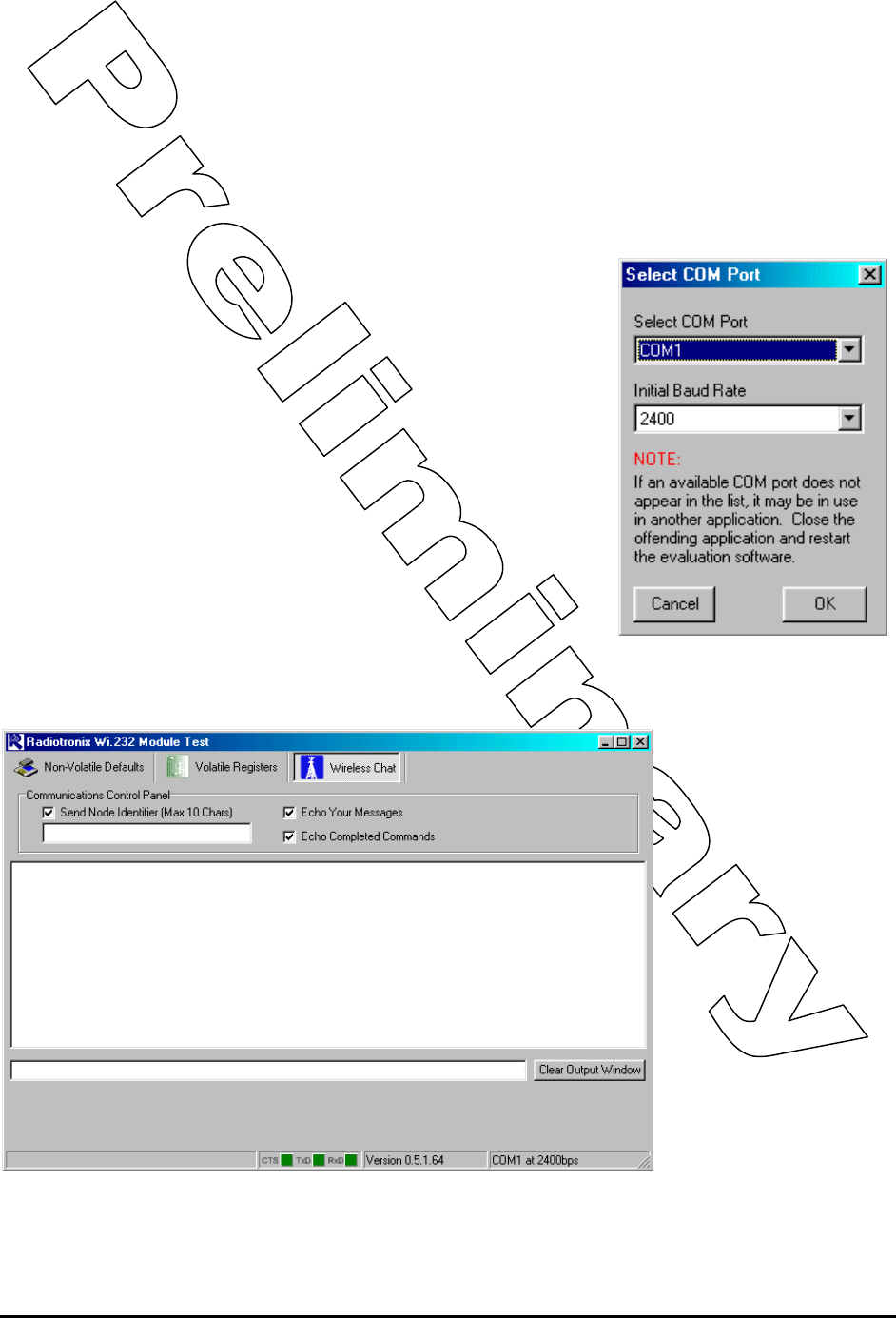
3.1 COM Port Setup and Selection.
Upon starting the Wi.USB-DTS™ evaluation software, you will be
presented with a COM port selection dialog box. Make sure that the
Wi.USB-DTS™ unit is already connected to the computer via the USB
cable before you start the software. This will ensure that the virtual
COM port which is assigned to the USB to UART bridge controller by
Windows is visible in the COM port selection list. Select the COM port
used by the Wi.USB-DTS™ . If you need to find out which COM port
this is, go to Control Panel > System Properties > Hardware Tab >
Device Manager > Ports (COM & LPT) > CP2101 USB to UART.
The first time you start the Wi.USB-DTS™ evaluation software, the
Baud Rate should be left at 2400 baud, since this is the factory default
baud rate setting for the unit.
Tip: The Wi.USB-DTS™ evaluation software does not auto-detect the
baud rate of the module. If you have changed the Non-Volatile Data
Rate register, you will have to select the baud rate you set this register
to when you start the Wi.USB-DTS™ evaluation software.
3.2 Wireless Chat Page.
The Wireless Chat page
in the Wi.USB-DTS™
evaluation software
demonstrates the
capability of the Wi.USB-
DTS™ to be used as a
wireless communications
link. Wi.USB-DTS™ works
as a wireless chat link
with no register changes
required, out of the box.
To Use Wireless Chat:
Type a message in the
lower text field and press
Enter. The text you typed
will be displayed on the
remote system, prefixed
with a Node Identifier if
you specified one.
RK-Wi.232DTS-FCC Rapid Development Kit User’s Manual
© 2006 Radiotronix Inc, all rights reserved - 5 - 3/29/2006
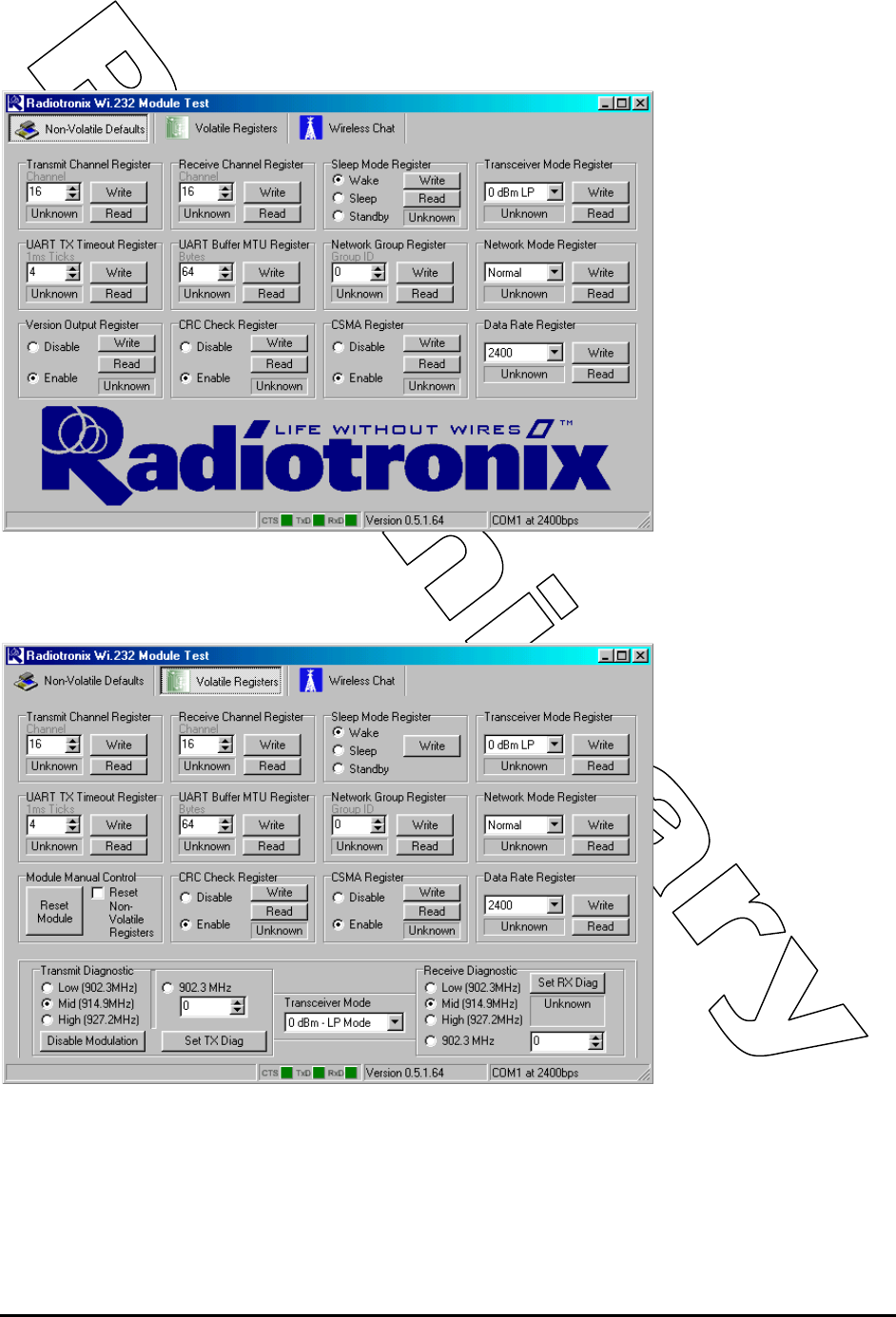
3.3 Non-Volatile Register Page.
The Non-Volatile Register
page in the evaluation
software allows you to
change the default
settings which will be
loaded when the module
is powered on.
It is important to note that
data rates in excess of
19.2kbps cannot be
achieved in LP mode due
to bandwidth limitations.
Tip: If you change the
Non-Volatile Data Rate
setting, you will have to
select this baud rate when
you start the Wi.USB-
DTS™ evaluation
software.
3.4 Volatile Register Page
In this page, you can
change the Volatile
settings of the module.
Values programmed into
these registers are lost of
power-down.
The page also provides a
means of switching the
receiver and transmitter
on and off, setting receive
and transmit channels,
transceiver mode and
modulation settings.
It is important to note that
data rates in excess of
19.2kbps cannot be
achieved in LP mode due
to bandwidth limitations.
RK-Wi.232DTS-FCC Rapid Development Kit User’s Manual
© 2006 Radiotronix Inc, all rights reserved - 6 - 3/29/2006
4 Evaluation Software Functions
4.1 Setting Register Values.
On both the Volatile and Non-Volatile pages, the registers are labeled by function. To set a register value,
select the value from the options available for that register and click the “Write” button. To perform a read
of that register, simply click the “Read” button. Descriptions of the register functions can be found in the
Wi.232DTS™ User’s Manual.
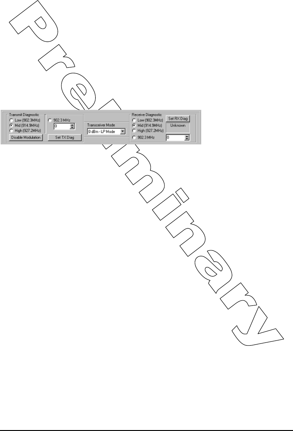
4.2 Diagnostic Mode Commands
There are a special class of commands available through the evaluation software. These controls are
located on the “Volatile Registers” page as seen below.
These commands place the module into special diagnostic modes that can be used to test the module’s
performance, or to activate the transmitter for RF testing purposes. It is important to note that once a
module executes a diagnostic command, it should be reset or have the power cycled to return to normal
operation.
4.2.1 Transceiver Mode
This selects the modulation mode and power output of both the transmitter and receiver. The mode is not
set until “Set TX Diag” or “Set RX Diag” is pressed. If “Set RX Diag” is pressed, the power output value is
ignored.
4.2.2 Transmit Diagnostic
Transmit Diagnostic consists of four radio buttons which select the transmit channel. Low, Mid and High
are quick reference buttons which can be used to select the lowest, the middle, or the highest channel.
Any specific channel can be selected by using the controls below the “Set TX Diag” button.
The “Set TX Diag” button switches the transmitter on using the channel and mode selected in the channel
selector and transceiver mode controls.
A “…1010101010101…” bit pattern is transmitted for bit error testing with another system or RF carrier
analysis.
4.2.3 Receive Diagnostic
Receive Diagnostic consists of four radio buttons which select the transmit channel. Low, Mid and High
are quick reference buttons which can be used to select the lowest, the middle, or the highest channel.
Any specific channel can be selected by using the controls above the “Set RX Diag” button.
The “Set RX Diag” button switches on the receiver using the channel and mode selected in the channel
selector and transceiver mode controls. Additionally, the module enters the diagnostic bit error test.
If a “…1010101010101…” bit pattern is received at the frequency and baud rate set up in the relevant
registers, the BER test will return the number and percent of bit errors. This information is displayed in
the panel below the “Set RX Diag” button. If no transmission is present, or the transmission is at the
wrong frequency or data rate, the module may enter an infinite loop waiting for the beginning of the data.
In this case, the module should be powered down and back up to return the module to its normal
operating mode.

RK-Wi.232DTS-FCC Rapid Development Kit User’s Manual
© 2006 Radiotronix Inc, all rights reserved - 7 - 3/29/2006
5 Notes
5.1 Microsoft Windows / Hilgraeve HyperTerminal
The Wi.USB-DTS™ can be used with HyperTerminal to receive and transmit RS-232 data and send files
using file transfer protocols such as ZMODEM. HyperTerminal and many other terminal programs assert
RTS by default. In the Wi.USB-DTS™, the RTS line is tied to the CMD pin on the module inside the
Wi.USB-DTS™ . When the CMD pin is held low, which is the case when the RTS line is asserted, the
module will be placed in command mode.
In command mode, all UART data sent to the module will be interpreted as commands and will NOT be
sent to the RF engine for transmission. Additionally, if a Wi.USB-DTS™ is powered on in the presence of
an asserted RTS line, it will perform a full hardware and flash reset to the factory defaults.
To use the Wi.USB-DTS™ with HyperTerminal or other terminal program, you must remove the cover,
locate the jumper “JP2”, and remove it. Removing this jumper will disconnect the RTS line from the CMD
pin on the Wi.232DTS™ module inside, allowing normal operation. It must be noted that while this jumper
is removed, commands cannot be sent to the Wi.USB-DTS™ . Everything sent to the Wi.USB-DTS™ will
be sent over RF.

RK-Wi.232DTS-FCC Rapid Development Kit User’s Manual
© 2006 Radiotronix Inc, all rights reserved - 8 - 3/29/2006
6 FCC Statements of Compliance
6.1 Class B Digital Device Statement
FCC NOTICE (FCC ID: Q7V-3F090012X)
This product has been tested and complies with the specifications for a
Class B digital device, pursuant to Part 15 of the FCC Rules. These limits
are designed to provide reasonable protection against harmful interference
in a residential installation. This equipment generates, uses, and can
radiate radio frequency energy and, if not installed and used according to
the instructions, may cause harmful interference to radio communications.
However, there is no guarantee that interference will not occur in a
particular installation. If this equipment does cause harmful interference to
radio or television reception, which is found by turning the equipment off
and on, the user is encouraged to try to correct the interference by one or
more of the following measures:
• Reorient or relocate the receiving antenna
• Increase the separation between the equipment or devices
• Connect the equipment to an outlet other than the receiver's
• Consult a dealer or an experienced radio/TV technician for
assistance
Product:
Wi.USB-DTS™
FCC ID: Q7V-3F090012X

RK-Wi.232DTS-FCC Rapid Development Kit User’s Manual
© 2006 Radiotronix Inc, all rights reserved - 9 - 3/29/2006
6.2 Declaration of Conformity
FCC NOTICE (FCC ID: Q7V-3F090012X)
This device complies with the rules set forth in Part 15 by the Federal
Communications Commission. Operation is subject to the following two
conditions:
1) This device may not cause harmful interference
2) This device must accept any interference received, including
interference that may cause undesired operation.
Any changes or modifications not expressly approved by Radiotronix, Inc.
could void the user’s authority to operate the equipment.
Responsible Party:
Radiotronix Inc.
905 Messenger Lane
Moore, OK 73160
phone: (405) 794-7730
Product:
Wi.USB-DTS™
FCC ID: Q7V-3F090012X

RK-Wi.232DTS-FCC Rapid Development Kit User’s Manual
© 2006 Radiotronix Inc, all rights reserved - 10 - 3/29/2006
6.3 Radiation Exposure Statement
6.4 Modifications
FCC NOTICE (FCC ID: Q7V-3F090012X)
The antennas used for this transmitter must not be co-located or operating
in conjunction with any other antenna or transmitter.
Product:
Wi.USB-DTS™
FCC ID: Q7V-3F090012X
FCC NOTICE (FCC ID: Q7V-3F090012X)
Changes or modifications not expressly approved by the party responsible
for compliance could void the user's authority to operate the equipment.
Product:
Wi.USB-DTS™
FCC ID: Q7V-3F090012X