Linx Technologies CMD-HHCP-XXXA Compact Handheld Transmitter User Manual CMD HHCP Manual 4 29 05
Linx Technologies Compact Handheld Transmitter CMD HHCP Manual 4 29 05
Users Manual
DESCRIPTION
The Linx CMD-HHCP-xxx-*** Remote
Command Unit is ideal for general-purpose
remote control and command applications.
This unit has been pre-certified for FCC Part
15, Industry Canada, and CE (433MHz only)
compliance, reducing development costs and
time to market. Available in 315, 418
(standard), or 433.92MHz, this compact
remote has a transmission range of up to
1,000 feet when combined with the LR Series
receiver. The transmitter unit can be
configured with 1 to 8 buttons and the keypad
and labeling can be modified to meet specific
OEM customer requirements. Selectable
addressing provides security and allows the
creation of up to 1024 distinct transmitter-
receiver relationships. The address can be
easily changed via an externally accessible
DIP switch. The transmission can be
decoded using a matching Linx Function
Module, KH Series receiver/decoder, or a
Linx LC or LR Series receiver paired with a
decoder IC or microcontroller. The unit uses
a single 3V CR-2032 lithium button cell.
FEATURES
FCC, Canada, and CE pre-certified
1 to 8 buttons
Small package
Customizable keypad
APPLICATIONS INCLUDE
General Remote Control
Keyless Entry
Garage / Gate Openers
Lighting Control
Call Systems
Home / Industrial Automation
Wire Elimination
OEM Configurations
With a one-time NRE and minimum
order, Linx can configure the keypad
and label areas to meet your specific
requirements. Contact Linx for details.
OEM COMPACT HANDHELD TRANSMITTER DATA GUIDE
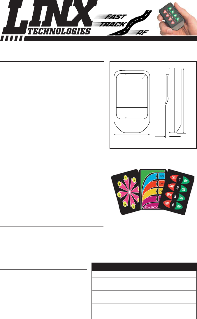
2.00"
1.35"
R 0.2"
2.81"
1.62" 0.60"0.20"
Revised 4/29/05
PART NUMBER DESCRIPTION
CMD-HHCP-xxx-*** 8-Button Handheld Transmitter
EVAL-xxx-HHCP HHCP Evaluation System
xxx = 315, 418 (Standard), 433.92 MHz
*** = Color Leave blank for standard Black
WHT = White CGY= Gray CBL = Blue
CRE = Red CPU = Purple
ORDERING INFORMATION
Figure 1: Physical Dimensions
WIRELESS MADE SIMPLE
Page 3
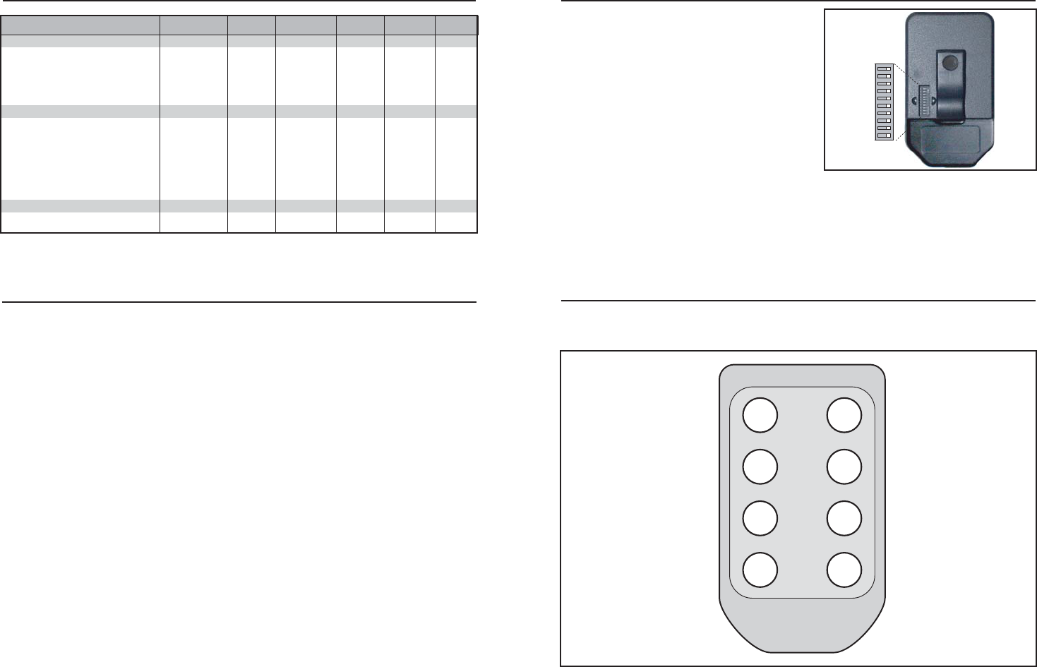
SETTING THE TRANSMITTER ADDRESS
The Compact Hand Held transmitter
allows the selection of one of 1024
unique addresses. All transmitters are
supplied set to the same address. To
avoid contention with other units or to
create unique relationships, the address
can be changed. This is accomplished
using internal DIP switches as shown.
The switches are accessed by removing
the DIP switch access cover on the back
of the transmitter.
If the switch is on, the address line is
connected to ground, otherwise it is floating. The receiver's address must match
exactly in order for the units to communicate. Application Note AN00300
describes in detail how to set the address to match any of the receivers offered
by Linx. This note can be found in the Support section of the Linx web site,
www.linxtechnologies.com.
CMD-HHCP BUTTON ASSIGNMENTS
This diagram illustrates the relationship between the button locations and
encoder/decoder data lines.
D7 D6
D5 D4
D3 D2
D1 D0
Page 2
OFF ON
A0 = 1
A1 = 2
A2 = 3
A3 = 4
A4 = 5
A5 = 6
A6 = 7
A7 = 8
A8 = 9
A9 = 10
Figure 2: DIP Switch Assignments
Figure 3: CMD-HHCP-xxx Button Assignments
ELECTRICAL SPECIFICATIONS
PPaarraammeetteerrDDeessiiggnnaattiioonnMMiinn..TTyyppiiccaallMMaaxx..UUnniittssNNootteess
POWER SUPPLY
Operating Voltage VCC 2.1 3.0 3.6 VDC –
Supply Current ICC –3.4 –mA –
Power-down Current IPDN –50 –nA 1
TRANSMITTER SECTION
Transmit Frequency Range FC
CMD-HHLR-315 –315 –MHz –
CMD-HHLR-418 –418 –MHz –
CMD-HHLR-433 – 433.92 – MHz –
Center Frequency Accuracy –-50 –+50 kHz –
ENVIRONMENTAL
Operating Temperature Range – -40 – +85 °C1
1. Characterized, but not tested.
Notes
THEORY OF OPERATION
The CMD-HHCP-xxx Remote Command Unit combines the LR Series
transmitter with an internal Splatch Series antenna with an on-board Holtek
HT640 encoder IC to form a simple, yet highly reliable, RF remote-control
transmitter. The LR transmitter is a low-cost, high-performance synthesized
ASK/OOK transmitter. The transmitter’s synthesized architecture delivers
outstanding stability and frequency accuracy while minimizing the effects of
antenna port loading and mismatching. This reduces or eliminates frequency
pulling, bit contraction, and other negative effects that are common to SAW-
based transmitter architectures, providing a significantly higher level of
performance and reliability.
When a button is pressed on the remote unit, power is applied to the internal
circuitry and the encoder IC is enabled. The encoder then detects the logic states
of the address lines and button data lines. These states are formatted into a
three-word transmission cycle that continues until the button is released. The
encoder data is used to modulate the transmitter, which, through the antenna,
conveys the data into free space. On the receiver side, a decoder IC or custom
microcontroller is used to check the transmitter's address bits against the
address settings of the receiving device. If a match is confirmed, the decoder’s
outputs are set to replicate the transmitter’s button states. These outputs can
then be used to activate external circuitry required by the application.
The transmitter is compatible with several Linx receiver products, including the
LC, LR, KH, and OEM product families. For applications where range is critical,
the LR Series receiver is the best choice due to its outstanding sensitivity. When
the transmitter is combined with an LR Series receiver and the HT658 decoder
chip, ranges up to 1000 feet are possible. Applications operating over shorter
distances will also benefit from the increased link reliability and superior noise
immunity provided by the LR Series receiver.
Page 5Page 4
INSTRUCTION TO THE USER
This device complies with Part 15 of the FCC Rules.
Operation of this device is subject to the following two conditions:
(1) This device may not cause harmful interference, and
(2) this device must accept any interference received, including interference
that may cause undesired operation.
This equipment has been tested and found to comply with the limits for a Class
B digital device, pursuant to Part 15 of the FCC Rules. These limits are
designed to provide reasonable protection against harmful interference in a
residential installation. This equipment generates, uses and can radiate radio
frequency energy and, if not installed and used in accordance with the
instructions, may cause harmful interference to radio communications.
However, there is no guarantee that interference will not occur in a particular
installation. If this equipment does cause harmful interference to radio or
television reception, which can be determined by turning the equipment off and
on, the user is encouraged to try to correct the interference by one or more of
the following measures:
Reorient or relocate the receiving antenna.
Increase the separation between the equipment and receiver.
Connect the equipment into an outlet on a circuit different from that to which the
receiver is connected.
Consult the dealer or an experienced radio/TV technician for help.
This equipment has been certified to comply with the limits for a Class B
computing device, pursuant to FCC Rules. In order to maintain compliance with
FCC regulations, shielded cables must be used with this equipment. Operation
with non-approved equipment or unshielded cables is likely to result in
interference to radio and TV reception. The user is cautioned that changes and
modifications made to the equipment without the approval of manufacturer
could void the user's authority to operate this equipment.
Place the above statement in the instruction manual or insert card.
COMPLIANCE REQUIREMENTS
The CMD-HHCP-xxx has been pre-certified by Linx Technologies for FCC Part
15 and Industry Canada RSP-100 compliance. The 433.92MHz version has also
been tested for CE compliance for use in the European Union. The 315MHz and
418MHz versions are not legal for use in Europe.
LABELING/INSTRUCTION REQUIREMENTS
The CMD-HHCP-xxx Remote Command Unit has already been labeled in
accordance with FCC, Industry Canada, and CE regulations in effect as of the
date of this document. No further labeling of the unit is needed; however, it is
necessary to include the following statement in the end product’s instruction
manual or insert card.
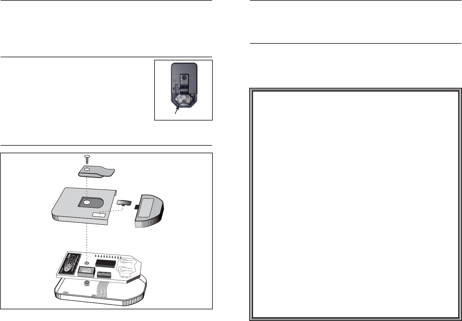
Figure 5: CMD-HHCP-xxx Assembly
CONTENTION CONSIDERATIONS
It is important to understand that only one transmitter at a time can be activated
within a reception area. While the transmitted signal consists of encoded digital
data, only one carrier of any particular frequency can occupy airspace without
contention at any given time. If two transmitters are activated in the same area
at the same time, then the signals will interfere with each other and the decoder
will not see a valid transmission, so it will not take any action.
BATTERY REPLACEMENT
The remote unit utilizes a standard CR-2032 Lithium
Button Cell. In normal use it will provide 1 to 2 years of
operation. To replace the battery, remove the access
cover by pressing down firmly on the label area and
sliding it off. Once the unit is open, remove the battery
by sliding it from beneath the holder. Replace it with
the same type of battery while observing the polarity
shown in the adjacent figure.
ASSEMBLY DIAGRAM
Battery Access
+
Figure 4: Battery Access
Page 6
VCC
R1
390K
SW1 1
SW2 2
SW3 3
SW4 4
SW5 5
SW6 6
SW7 7
SW8 8
COM 9
SM1
RFIN
1
GND
2
GND
3
GND
4
GND
5
GND
6
ANT1
SPLATCH ANTENN
A
R2
100K
VCC
1
23
4U3
DPAK-X2
1
23
4U2
DPAK-X2
1
23
4U4
DPAK-X2
1
23
4U5
DPAK-X2
D1
1
D2
2
D3
3
D4
4
D5
5
D6
6
D7
7
DOUT
8
TE
9
OSC1
10
OSC2
11
GND
12 A0 13
A1 14
A2 15
A3 16
A4 17
A5 18
A6 19
A7 20
A8 21
A922
D0 23
VCC 24
U1
HT-640
1
2
3
20
19
18
4
5
6
17
16
15
7
8
9
14
13
12
1011
S1
SW-USMT-10
GND
GND
GND
GND
VCC
GND
R3
Set For FCC
Compliance
GND
1
DATA IN
2
GND
3
IADJ/VCC
4RF OUT 5
GND 6
VCC 7
PDN 8
TX1
LRTX
GND
GND
VCC
VCC
GND
B1
BAT-LINX2032
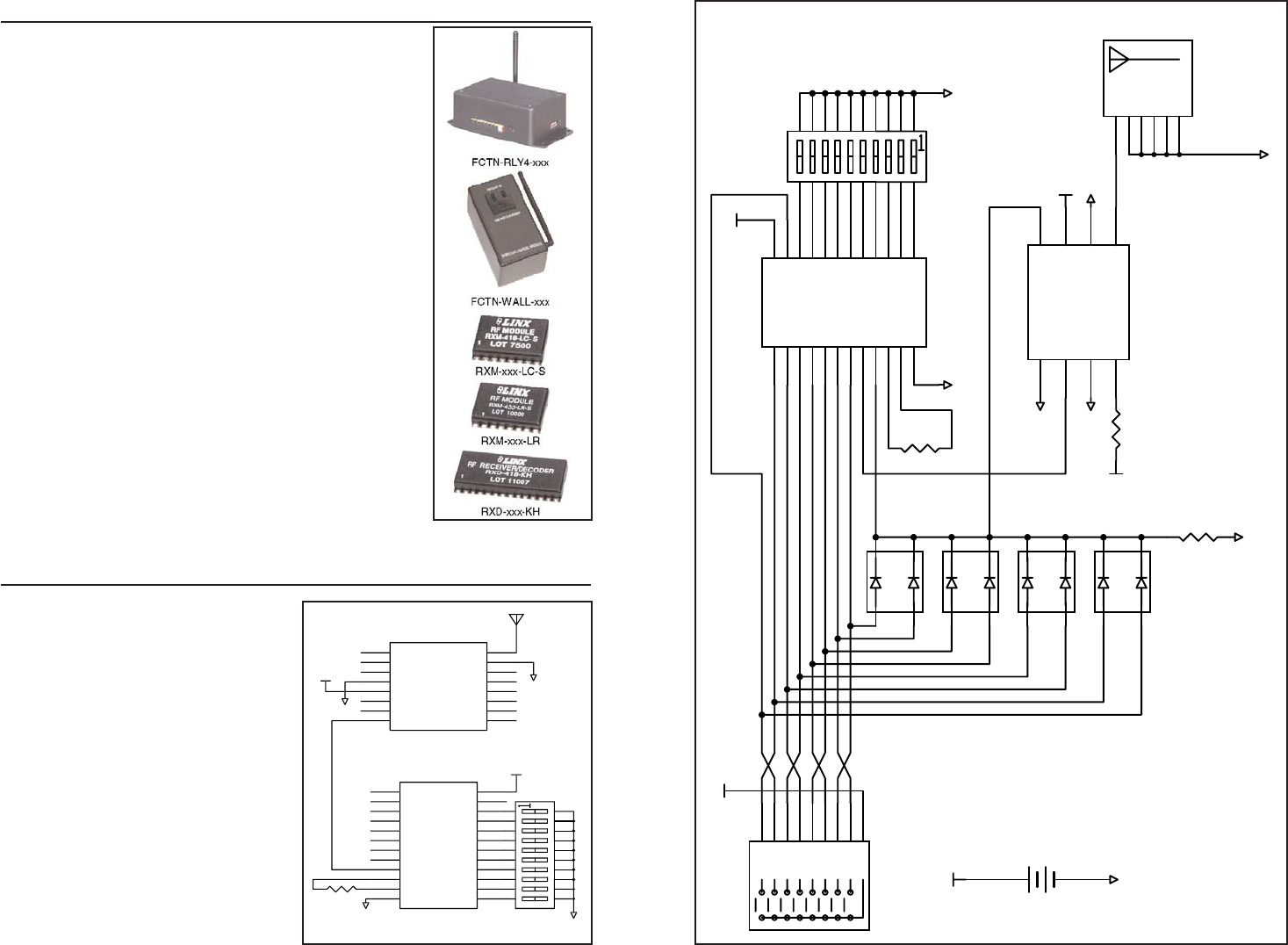
Figure 7: CMD-HHCP-xxx Schematic
Page 7
RECEIVERS
There are four options for receivers within the Linx
product line. The first option is to use one of the OEM
Function Modules, such as the Relay Module or the AC
Wall Module. These items are also pre-certified and
can be immediately included in a product.
The other options are to use one of the Linx receiver
modules. The signal sent by the Compact Hand Held
transmitter can be received by the LC Series receiver
module or, for longer range, the LR Series receiver
module. These modules can be connected to the
Holtek HT658 decoder to decode the signal or a custom
microcontroller can be programmed to decode it and
take specific action.
The KH Series offers a slightly simpler solution by
combining the LC Series receiver and the HT658
decoder in a single package.
The basic operation for the system is that when a
button is pressed on the transmitter, a corresponding
pin on the decoder will go high (as long as the
addresses match). This can then be connected to
whatever circuitry is required by the application
Application Note AN00300 discusses in detail how to
set the addresses on all of the units. Data guides for all
of the receivers, the HT640 encoder, and the HT658
decoder can be found on the Linx Technologies web
site, www.linxtechnologies.com.
TYPICAL APPLICATIONS
The outstanding sensitivity of the LR
Series receiver offers the best range
when used with the Hand Held
transmitter. When using the LR
Series receiver, the Holtek HT658
decoder chip should be used to
decode the received signal. This
decoder has ten address lines that
must match the transmitter address
lines. A DIP switch is commonly
used to set these, but they can also
be hardwired. If the address lines
match, when a button on the
transmitter is pressed a
corresponding data line on the
decoder (D0-D7) will go high. These
data lines can then be connected to
external circuitry to perform
whatever function is required by the
application.
G
N
D
R1
390k
G
N
D
G
N
D
V
CC
V
CC
D1
1
D2
2
D
3
3
D4
4
D
5
5
D
6
6
D7
7
VT
8
DIN
9
OSC1
1
0
OSC2
11
G
N
D
12
A
0
1
3
A
1
14
A
2
1
5
A
3
1
6
A4
17
A
5
1
8
A
6
1
9
A7
2
0
A
8
21
A
9
22
D
0
2
3
V
CC
24
HT
658
N
C
1
N
C
2
N
C
3
G
N
D
4
V
CC
5
PDN
6
R
SSI
7
DATA
8
N
C
9
N
C
1
0
N
C
11
N
C
12
N
C
1
3
N
C
14
G
N
D
1
5
ANT
1
6
RXM-XXX-LR-
S
G
N
D
Figure 6: LR Receiver and HT658 Schematic

LINX TECHNOLOGIES, INC.
575 S.E. ASHLEY PLACE
GRANTS PASS, OR 97526
PHONE: (541) 471-6256
FAX: (541) 471-6251
www.linxtechnologies.com
U.S. CORPORATE HEADQUARTERS
Linx Technologies is continually striving to improve the quality and function of its products; for
this reason, we reserve the right to make changes without notice. The information contained in
this Data Sheet is believed to be accurate as of the time of publication. Specifications are based
on representative lot samples. Values may vary from lot to lot and are not guaranteed. Linx
Technologies makes no guarantee, warranty, or representation regarding the suitability or
legality of any product for use in a specific application. None of these devices is intended for
use in applications of a critical nature where the safety of life or property is at risk. The user
assumes full liability for the use of product in such applications. Under no conditions will Linx
Technologies be responsible for losses arising from the use or failure of the device in any
application, other than the repair, replacement, or refund limited to the original product purchase
price. Some devices described in this publication are patented. Under no circumstances shall
any user be conveyed any license or right to the use or ownership of these patents.
Disclaimer
WIRELESS MADE SIMPLE
© 2005 by Linx Technologies, Inc. The stylized
Linx logo, Linx, and “Wireless Made Simple”
are the trademarks of Linx Technologies, Inc.
Printed in U.S.A.