Linx Technologies HUMA-900 HumPRO-A Series High Power Data Transceiver User Manual Trace Layout
Linx Technologies HumPRO-A Series High Power Data Transceiver Trace Layout
Contents
- 1. User Manual
- 2. Trace Layout Document
- 3. Trace Layout Reference
Trace Layout Document

HUM-A-900-PRO Trace Layout Guide
1 of 6
HUM-A-900-PRO Trace Layout
2/22/17
For proper integration of the HUM-A-900-PRO module in end products the following requirements must
be met. A host product incorporating the HUM-A-900-PRO module cannot take advantage of the pre-
existing certification of the component transmitter without conformity to the specific requirements in
these instructions.
1. Contents
2. Approved RF Connection (Edge Mount RP-SMA connection) ............................................................... 2
3. Alternate RF Connection (Vertical Mount RP-SMA connection) ........................................................... 4
4. Approved Antennas ............................................................................................................................... 6
5. Design Verification Test Procedures ...................................................................................................... 6
6. Production Test Procedures for Ensuring Compliance .......................................................................... 6
HUM-A-900-PRO Trace Layout Guide
2 of 6
2. Approved RF Connection (Edge Mount RP-SMA connection)
This is the preferred RF connection design and is approved with all operating modes of the module. This
design uses a PCB microstrip to connect the HUM-A-900-PRO module’s Antenna castellation to an edge
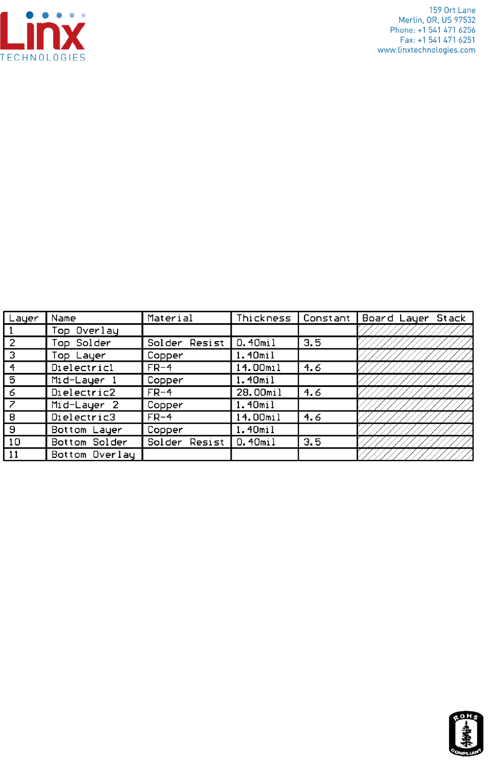
mount reverse polarity SMA connector Linx Part number CONREVSMA003.062. A 4 layer PCB is used in
this design. The Top layer 24mil RF trace and Mid-Layer 1 ground plane form an RF microstrip.
- Figure 1 shows the required layer stackup for this design and must be matched precisely
including material type, dielectric constant, dielectric thickness, and copper thickness.
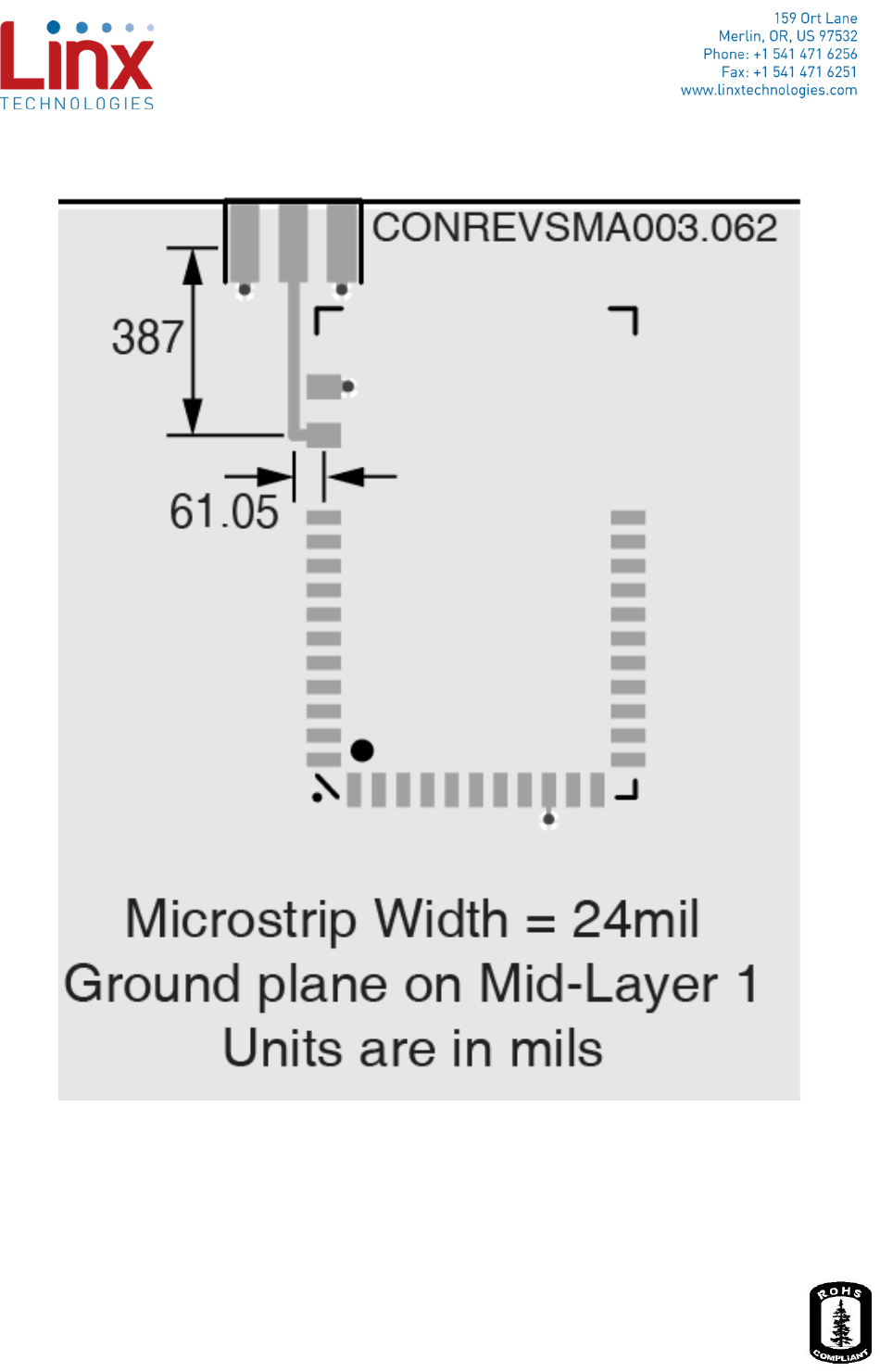
- Figure 2 shows the trace dimensions that must be followed precisely, including trace width, and
routing
- The Ground plane on Mid-layer 1 must not have any cutouts in the area under the RF trace or
the area between the module and the connector.
Figure 1 - PCB Stackup for Edge Mount RP-SMA
HUM-A-900-PRO Trace Layout Guide
3 of 6
Figure 2 - Trace Dimensions for Edge Mount RP-SMA
HUM-A-900-PRO Trace Layout Guide
4 of 6
3. Alternate RF Connection (Vertical Mount RP-SMA
connection)
The Vertical Mount RP-SMA RF connection is approved only for operation at the Low RF Data Rate
(19.2kbps) This design uses a PCB microstrip to connect the HUM-A-900-PRO module’s Antenna
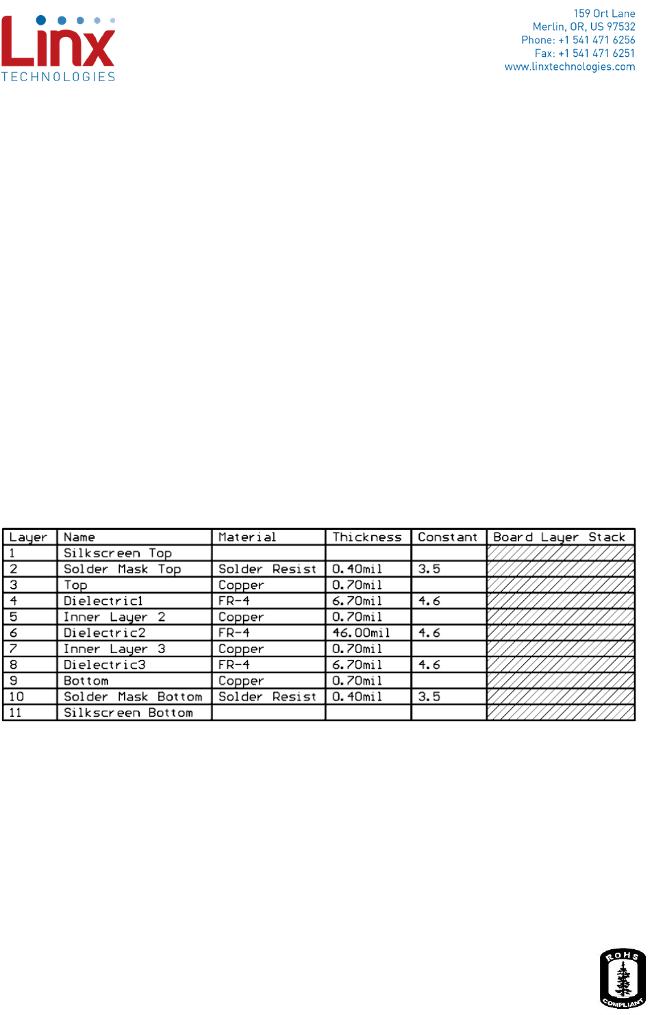
castellation to an edge mount reverse polarity SMA connector Linx Part number CONREVSMA001. A 4
layer PCB is used for this design. The Top layer 14mil RF trace and Mid-Layer 1 ground plane form an RF
microstrip.
- Figure 3 shows the required PCB layer stackup for this design and must be matched precisely
including dielectric material type, dielectric constant, dielectric thickness, and copper thickness
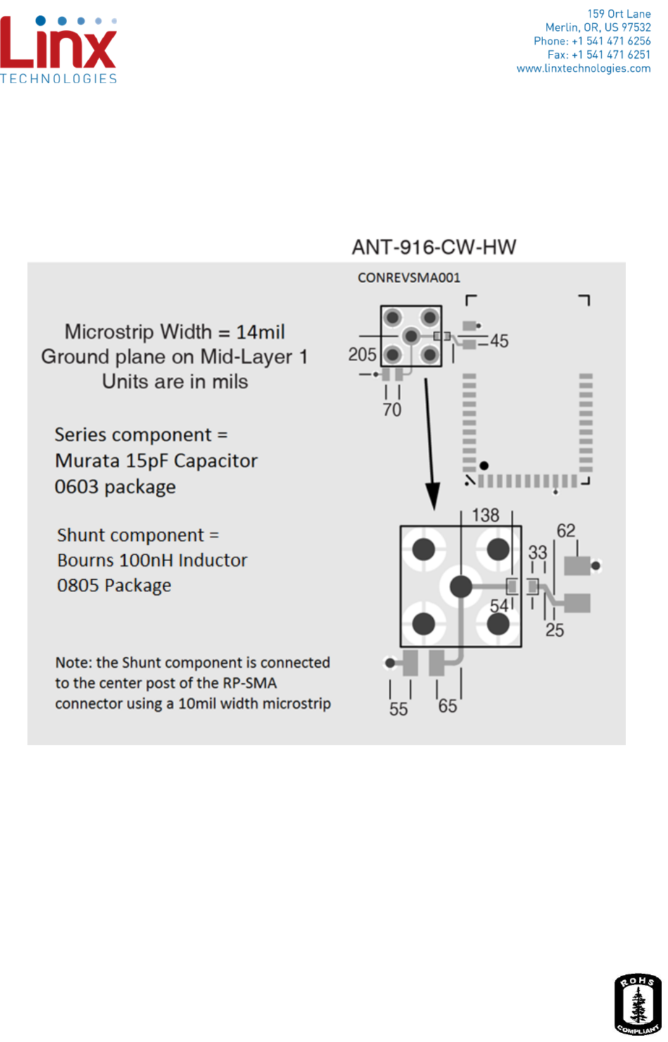
- Figure 4 shows the trace dimensions that must be followed precisely, including trace width,
routing, and RF matching components. A 15pF series capacitor (Murata
GRM0335C1H150GA01D) is located between the module and the RP-SMA connector for RF
matching. A 10mil microstrip connects the center post of the RP-SMA connector to a 100nH
inductor (Bourns CW201212-R10J) for RF matching.
- The Ground plane on Mid-layer 1 must not have any cutouts in the area under the RF trace, in
the area between the module and the connector, or under the RF matching components.
Figure 3 - PCB Stackup for Vertical Mount RP-SMA
HUM-A-900-PRO Trace Layout Guide
5 of 6
Note: The vertical SMA connector is a through-hole mount component. The connector must be
installed on the bottom of the PCB. Figure 4 shows the top side of the PCB were the HUM-A-900-
PRO module is mounted and the solder side of the RP-SMA connector is visible.
Figure 4 - Trace Dimensions and RF Matching Component Placement for Vertical Mount RP-SMA
HUM-A-900-PRO Trace Layout Guide
6 of 6
4. Approved Antennas
The antennas in Table 1 are tested and approved with both the Edge Mount and Vertical RP-SMA RF
connections. According to the FCC Permissive Change Policy (178919 D01) “Additional antennas that are
equivalent may be substituted, and then marketed without a Class II permissive change… Equivalent
antennas must be of the same type (e.g., yagi, dish, etc.), must be of equal or less gain than an antenna
previously authorized under the same grant of certification (FCC ID), and must have similar in-band and
out-of-band characteristics (consult specification sheet for cutoff frequencies). Contact Linx for
information about other antennas that meet these requirements and may be used with the HUM-A-900-
PRO module.
Manufacturer
Part number
Type
Peak Gain
Valid Connector
Linx
ANT-916-CW-HWR-RPS
½ Wave Dipole Helical
1.2dBi
Edge and Vertical
Table 1 - Approved Antennas
5. Design Verification Test Procedures
After the design is fabricated the following measurements should be executed to verify the design:
1. Mechanical measurement of dimensions specified in the Microstrip Dimensions diagrams above
2. Obtain and review the detailed layer stackup solution used for the build from the PCB
manufacturer that specifies dielectric thicknesses and target dielectric constants for substrate
materials.
Note: Linx Applications Engineers are available to review Layout designs to ensure compliance and
optimal RF performance.
6. Production Test Procedures for Ensuring Compliance
During production test for the host device, The HUM-A-900-PRO module is to be activated in maximum
power transmit mode and the conducted RF output power at the RP-SMA connector is to be measured
using a Spectrum Analyzer, RF Power Meter or other appropriate RF measurement equipment. The
conducted output power should not exceed the maximum output power specified in the HUM-A-900-
PRO Data Guide.