Linx Technologies HUMA-900 HumPRO-A Series High Power Data Transceiver User Manual Trace Layout Reference
Linx Technologies HumPRO-A Series High Power Data Transceiver Trace Layout Reference
Contents
- 1. User Manual
- 2. Trace Layout Document
- 3. Trace Layout Reference
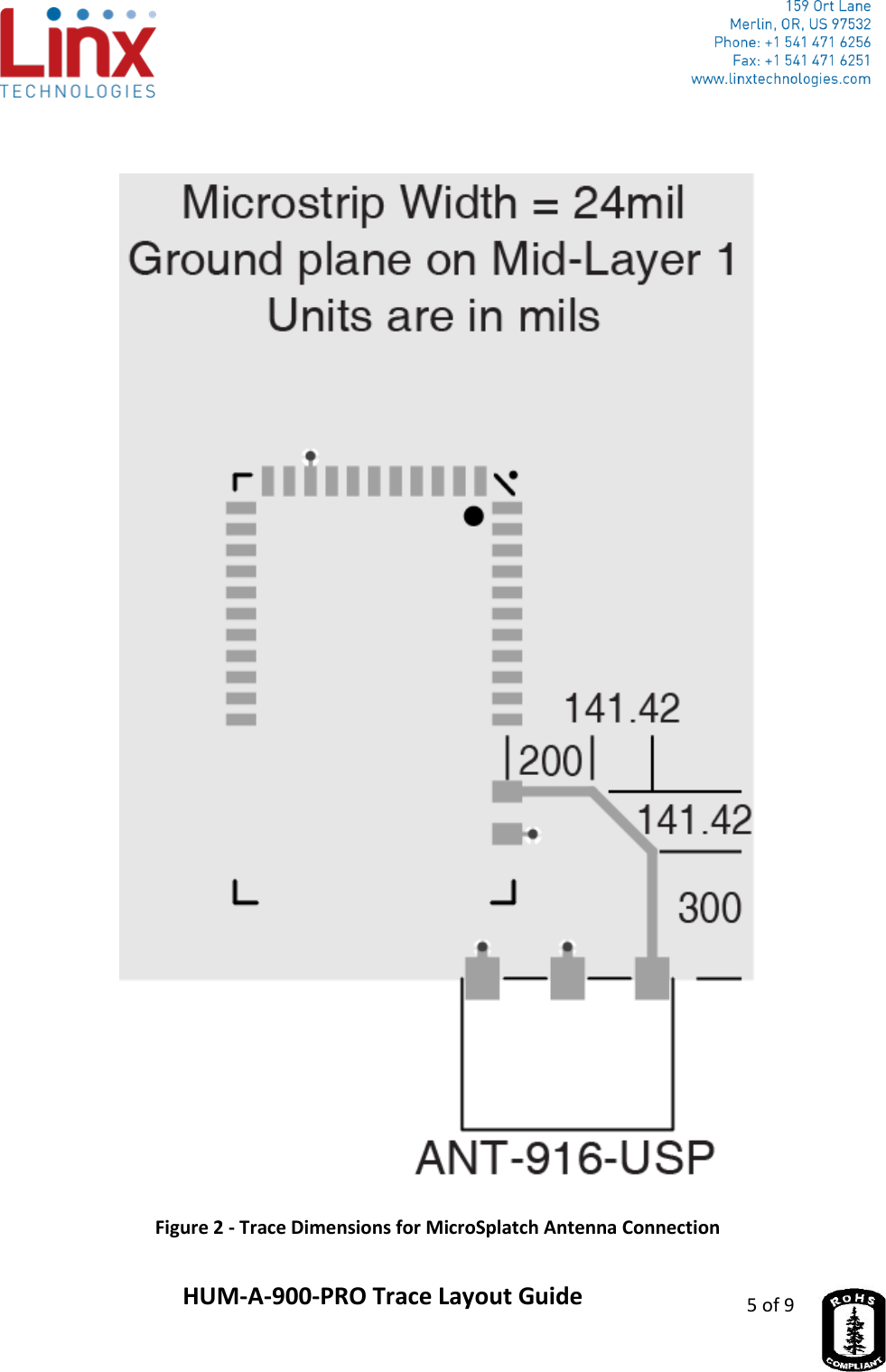
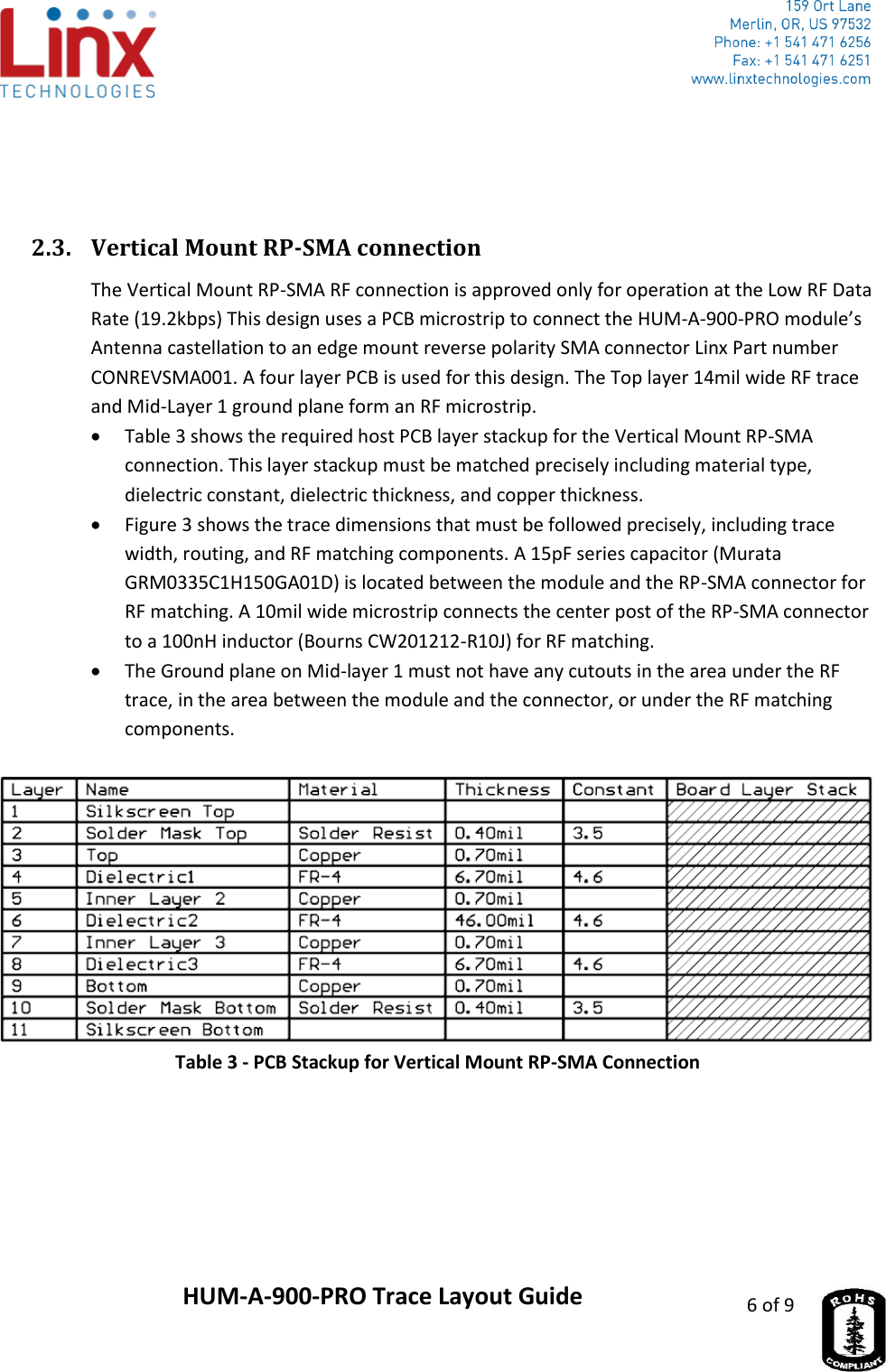
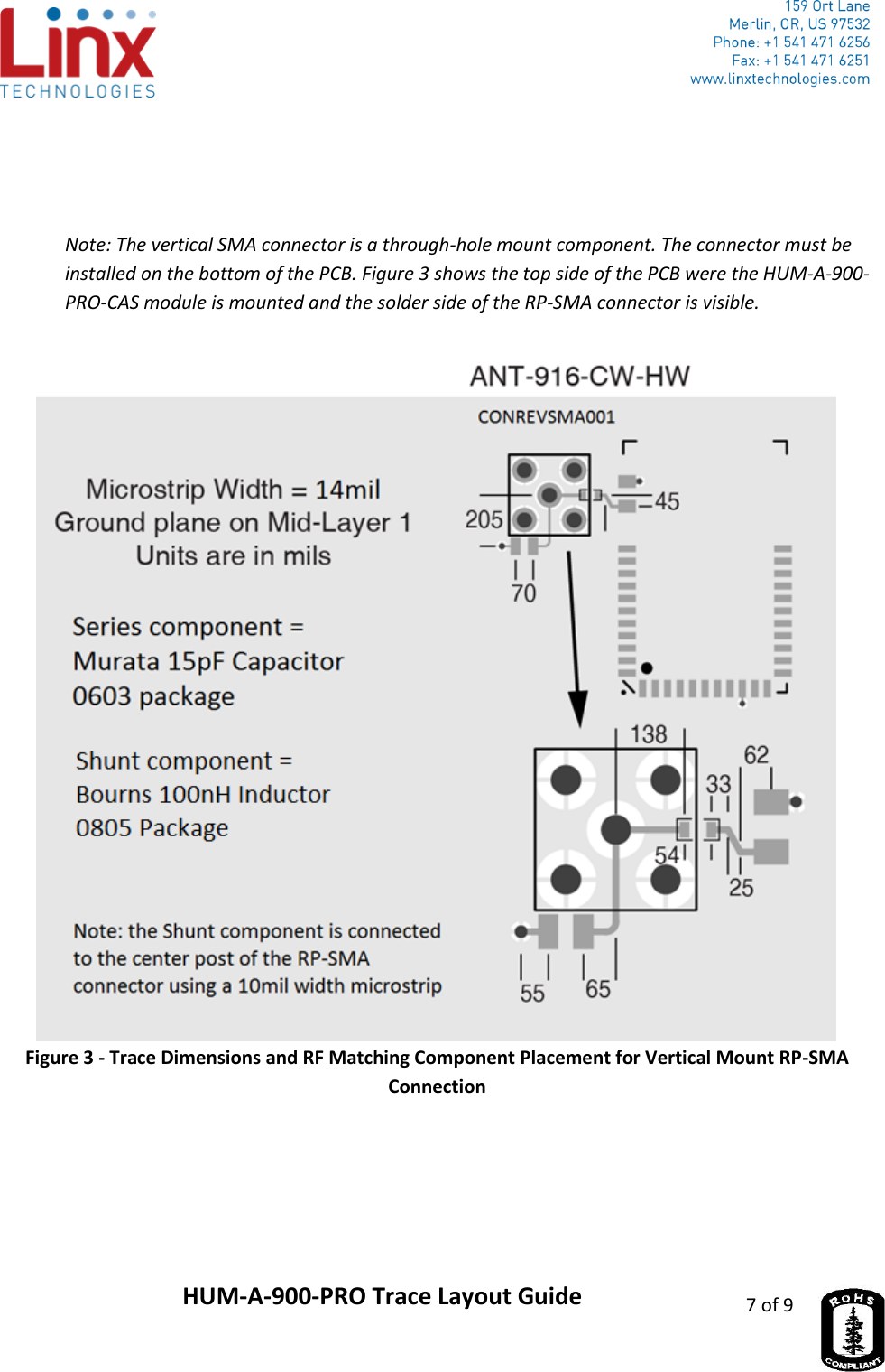
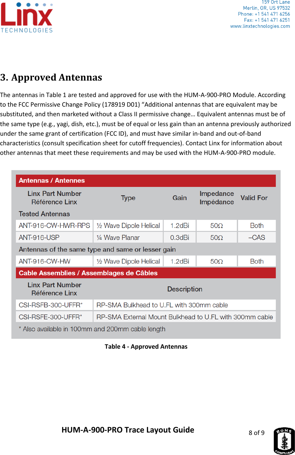
Trace Layout Reference