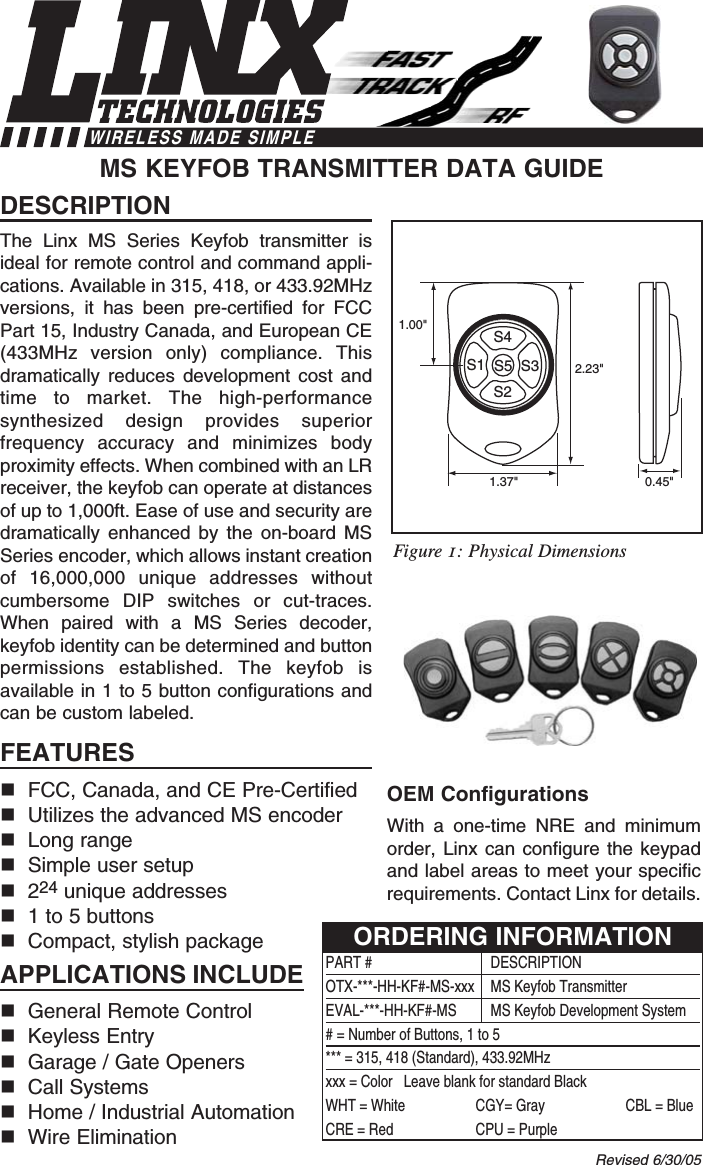
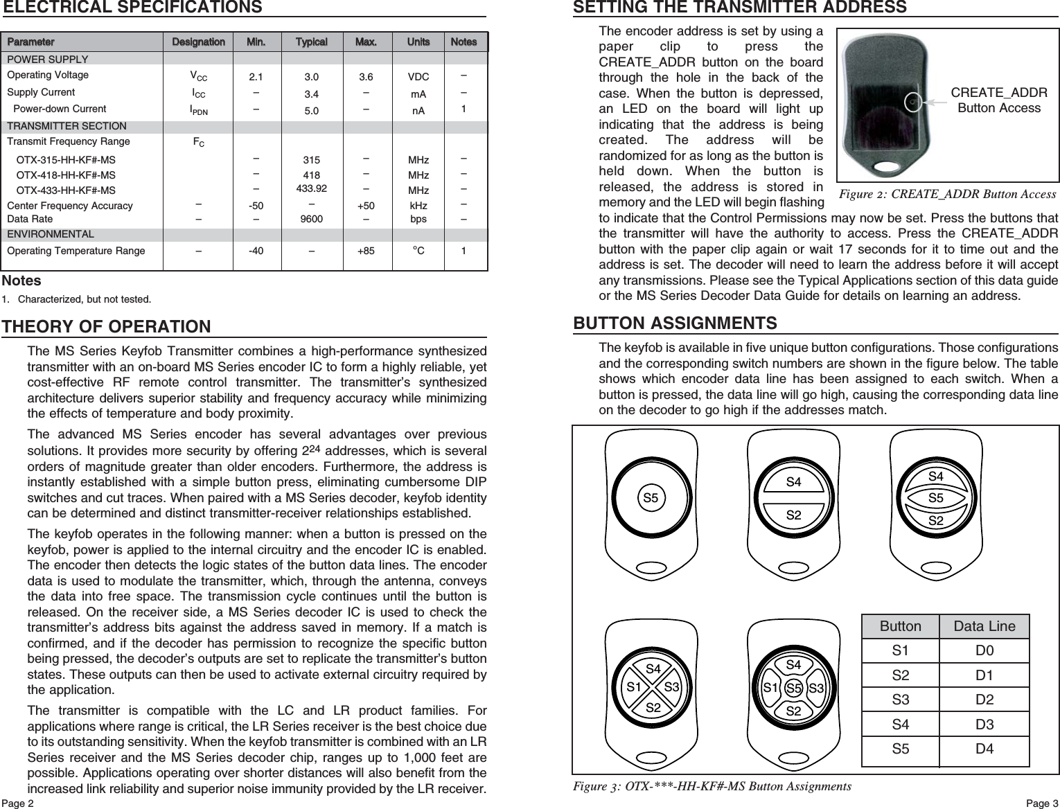
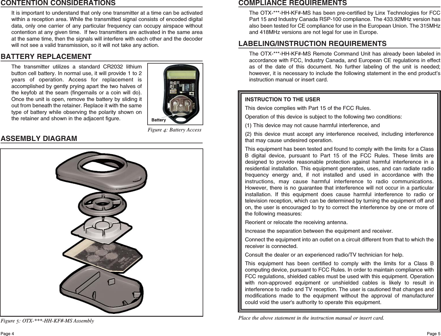
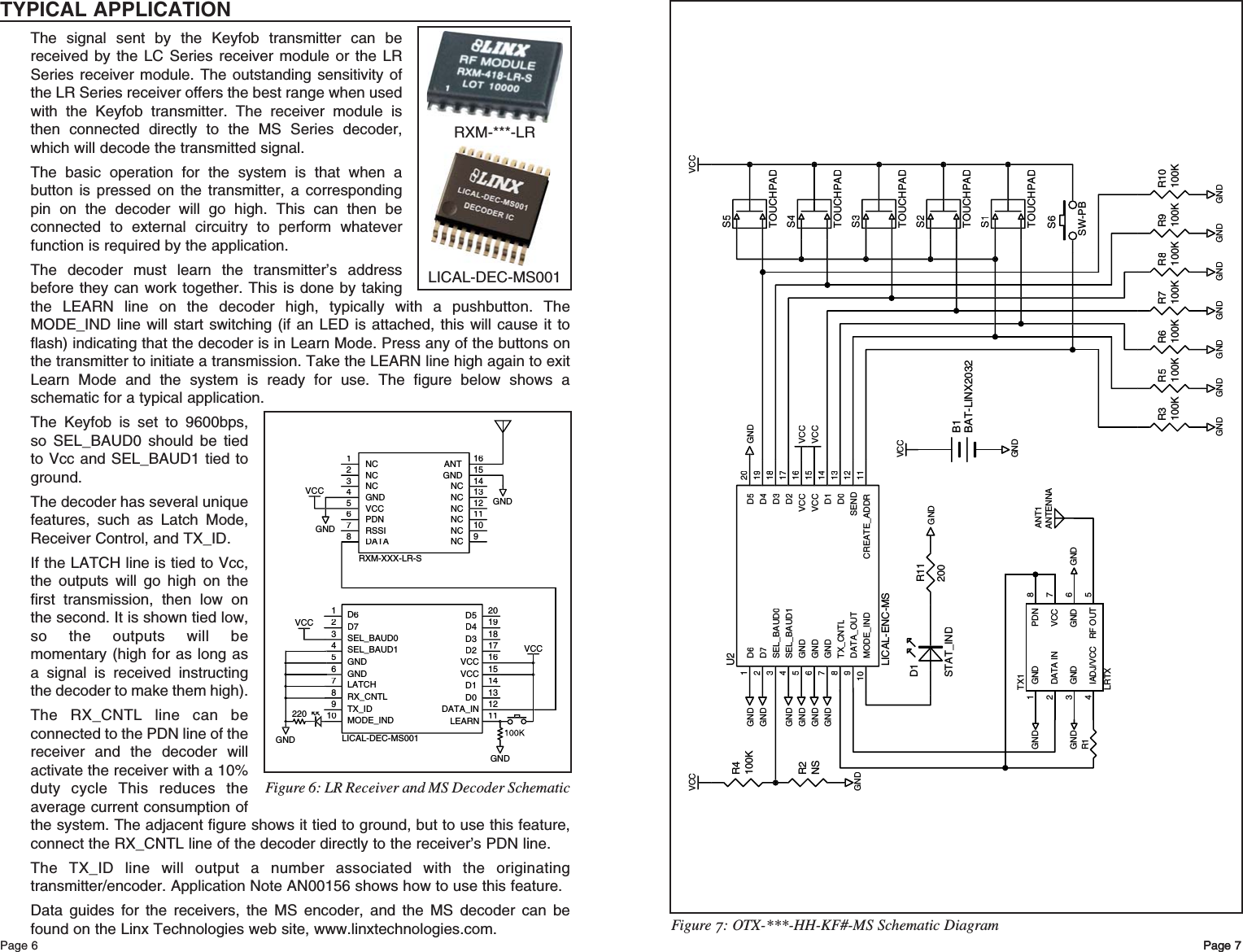
Linx Technologies OTX-XXX-KFMSA Keyfob Transmitter User Manual OTX xxx HH KF5 MS Manual 6 30 05

Linx Technologies Keyfob Transmitter OTX xxx HH KF5 MS Manual 6 30 05

Users Manual

DESCRIPTIONThe Linx MS Series Keyfob transmitter isideal for remote control and command appli-cations. Available in 315, 418, or 433.92MHzversions, it has been pre-certified for FCCPart 15, Industry Canada, and European CE(433MHz version only) compliance. Thisdramatically reduces development cost andtime to market. The high-performancesynthesized design provides superiorfrequency accuracy and minimizes bodyproximity effects. When combined with an LRreceiver, the keyfob can operate at distancesof up to 1,000ft. Ease of use and security aredramatically enhanced by the on-board MSSeries encoder, which allows instant creationof 16,000,000 unique addresses withoutcumbersome DIP switches or cut-traces.When paired with a MS Series decoder,keyfob identity can be determined and buttonpermissions established. The keyfob isavailable in 1 to 5 button configurations andcan be custom labeled. FEATURESFCC, Canada, and CE Pre-CertifiedUtilizes the advanced MS encoderLong rangeSimple user setup224 unique addresses1 to 5 buttonsCompact, stylish packageAPPLICATIONS INCLUDEGeneral Remote Control Keyless EntryGarage / Gate OpenersCall SystemsHome / Industrial AutomationWire EliminationOEM ConfigurationsWith a one-time NRE and minimumorder, Linx can configure the keypadand label areas to meet your specificrequirements. Contact Linx for details.MS KEYFOB TRANSMITTER DATA GUIDE2.23"1.00"0.45"1.37"S4S2S1 S3S5Revised 6/30/05PART # DESCRIPTIONOTX-***-HH-KF#-MS-xxx  MS Keyfob TransmitterEVAL-***-HH-KF#-MS MS Keyfob Development System# = Number of Buttons, 1 to 5*** = 315, 418 (Standard), 433.92MHzxxx = Color   Leave blank for standard BlackWHT = White CGY= Gray CBL = BlueCRE = Red CPU = PurpleORDERING INFORMATIONFigure 1: Physical DimensionsWIRELESS MADE SIMPLE
Page 3Page 2THEORY OF OPERATIONThe MS Series Keyfob Transmitter combines a high-performance synthesizedtransmitter with an on-board MS Series encoder IC to form a highly reliable, yetcost-effective RF remote control transmitter. The transmitter’s synthesizedarchitecture delivers superior stability and frequency accuracy while minimizingthe effects of temperature and body proximity.The advanced MS Series encoder has several advantages over previoussolutions. It provides more security by offering 224 addresses, which is severalorders of magnitude greater than older encoders. Furthermore, the address isinstantly established with a simple button press, eliminating cumbersome DIPswitches and cut traces. When paired with a MS Series decoder, keyfob identitycan be determined and distinct transmitter-receiver relationships established.The keyfob operates in the following manner: when a button is pressed on thekeyfob, power is applied to the internal circuitry and the encoder IC is enabled.The encoder then detects the logic states of the button data lines. The encoderdata is used to modulate the transmitter, which, through the antenna, conveysthe data into free space. The transmission cycle continues until the button isreleased. On the receiver side, a MS Series decoder IC is used to check thetransmitter’s address bits against the address saved in memory. If a match isconfirmed, and if the decoder has permission to recognize the specific buttonbeing pressed, the decoder’s outputs are set to replicate the transmitter’s buttonstates. These outputs can then be used to activate external circuitry required bythe application.The transmitter is compatible with the LC and LR product families. Forapplications where range is critical, the LR Series receiver is the best choice dueto its outstanding sensitivity. When the keyfob transmitter is combined with an LRSeries receiver and the MS Series decoder chip, ranges up to 1,000 feet arepossible. Applications operating over shorter distances will also benefit from theincreased link reliability and superior noise immunity provided by the LR receiver.SETTING THE TRANSMITTER ADDRESSThe encoder address is set by using apaper clip to press theCREATE_ADDR button on the boardthrough the hole in the back of thecase. When the button is depressed,an LED on the board will light upindicating that the address is beingcreated. The address will berandomized for as long as the button isheld down. When the button isreleased, the address is stored inmemory and the LED will begin flashingto indicate that the Control Permissions may now be set. Press the buttons thatthe transmitter will have the authority to access. Press the CREATE_ADDRbutton with the paper clip again or wait 17 seconds for it to time out and theaddress is set. The decoder will need to learn the address before it will acceptany transmissions. Please see the Typical Applications section of this data guideor the MS Series Decoder Data Guide for details on learning an address.BUTTON ASSIGNMENTSThe keyfob is available in five unique button configurations. Those configurationsand the corresponding switch numbers are shown in the figure below. The tableshows which encoder data line has been assigned to each switch. When abutton is pressed, the data line will go high, causing the corresponding data lineon the decoder to go high if the addresses match.S4S2S1 S3S5S5S2S5S4S4S2S4S1 S3S2Figure 3: OTX-***-HH-KF#-MS Button AssignmentsFigure 2: CREATE_ADDR Button AccessButton Data LineS1 D0S2 D1S3 D2S4 D3S5 D4ELECTRICAL SPECIFICATIONSPPaarraammeetteerrDDeessiiggnnaattiioonnMMiinn..TTyyppiiccaallMMaaxx..UUnniittssNNootteessPOWER SUPPLYOperating Voltage VCC 2.1 3.0 3.6 VDC –Supply Current ICC –3.4 –mA –Power-down Current IPDN –5.0 –nA 1TRANSMITTER SECTIONTransmit Frequency Range FCOTX-315-HH-KF#-MS –315 –MHz –OTX-418-HH-KF#-MS –418 –MHz –OTX-433-HH-KF#-MS – 433.92 – MHz –Center Frequency Accuracy –-50 –+50 kHz –Data Rate – – 9600 – bps –ENVIRONMENTALOperating Temperature Range – -40 – +85 °C11. Characterized, but not tested.NotesCREATE_ADDRButton Access
Page 5Page 4INSTRUCTION TO THE USERThis device complies with Part 15 of the FCC Rules.Operation of this device is subject to the following two conditions:(1) This device may not cause harmful interference, and(2) this device must accept any interference received, including interferencethat may cause undesired operation.This equipment has been tested and found to comply with the limits for a ClassB digital device, pursuant to Part 15 of the FCC Rules. These limits aredesigned to provide reasonable protection against harmful interference in aresidential installation. This equipment generates, uses, and can radiate radiofrequency energy and, if not installed and used in accordance with theinstructions, may cause harmful interference to radio communications.However, there is no guarantee that interference will not occur in a particularinstallation. If this equipment does cause harmful interference to radio ortelevision reception, which can be determined by turning the equipment off andon, the user is encouraged to try to correct the interference by one or more ofthe following measures: Reorient or relocate the receiving antenna. Increase the separation between the equipment and receiver. Connect the equipment into an outlet on a circuit different from that to which thereceiver is connected. Consult the dealer or an experienced radio/TV technician for help. This equipment has been certified to comply with the limits for a Class Bcomputing device, pursuant to FCC Rules. In order to maintain compliance withFCC regulations, shielded cables must be used with this equipment. Operationwith non-approved equipment or unshielded cables is likely to result ininterference to radio and TV reception. The user is cautioned that changes andmodifications made to the equipment without the approval of manufacturercould void the user's authority to operate this equipment. Place the above statement in the instruction manual or insert card.COMPLIANCE REQUIREMENTSThe OTX-***-HH-KF#-MS has been pre-certified by Linx Technologies for FCCPart 15 and Industry Canada RSP-100 compliance. The 433.92MHz version hasalso been tested for CE compliance for use in the European Union. The 315MHzand 418MHz versions are not legal for use in Europe.LABELING/INSTRUCTION REQUIREMENTSThe OTX-***-HH-KF#-MS Remote Command Unit has already been labeled inaccordance with FCC, Industry Canada, and European CE regulations in effectas of the date of this document. No further labeling of the unit is needed;however, it is necessary to include the following statement in the end product’sinstruction manual or insert card.Figure 5: OTX-***-HH-KF#-MS AssemblyCONTENTION CONSIDERATIONSIt is important to understand that only one transmitter at a time can be activatedwithin a reception area. While the transmitted signal consists of encoded digitaldata, only one carrier of any particular frequency can occupy airspace withoutcontention at any given time.  If two transmitters are activated in the same areaat the same time, then the signals will interfere with each other and the decoderwill not see a valid transmission, so it will not take any action.BATTERY REPLACEMENTThe transmitter utilizes a standard CR2032 lithiumbutton cell battery. In normal use, it will provide 1 to 2years of operation. Access for replacement isaccomplished by gently prying apart the two halves ofthe keyfob at the seam (fingernails or a coin will do).Once the unit is open, remove the battery by sliding itout from beneath the retainer. Replace it with the sametype of battery while observing the polarity shown onthe retainer and shown in the adjacent figure.ASSEMBLY DIAGRAMBattery+Figure 4: Battery Access
VCCGNDB1BAT-LINX2032GNDR4100KGNDS1TOUCHPADS2TOUCHPADS3TOUCHPADS4TOUCHPADS5TOUCHPADD61D72SEL_BAUD03SEL_BAUD14GND5GND6GND7TX_CNTL8DATA_OUT9MODE_IND10CREATE_ADDR11SEND12D013D114VCC15VCC16D217D318D419D520U2LICAL-ENC-MSVCCVCCVCCVCCGNDGNDGNDGNDS6SW-PBGNDGNDGNDGNDGNDGNDGNDR2NSR3100KR5100KR6100KR10100KR9100KR7100KR8100KGNDGNDGNDR11200D1STAT_INDGNDR1GND1DATA IN2GND3IADJ/VCC4RF OUT 5GND 6VCC 7PDN 8TX1LRTXGNDGND ANT1ANTENNAPage 6 Page 7Page 7Figure 7: OTX-***-HH-KF#-MS Schematic DiagramTYPICAL APPLICATIONThe signal sent by the Keyfob transmitter can bereceived by the LC Series receiver module or the LRSeries receiver module. The outstanding sensitivity ofthe LR Series receiver offers the best range when usedwith the Keyfob transmitter. The receiver module isthen connected directly to the MS Series decoder,which will decode the transmitted signal.The basic operation for the system is that when abutton is pressed on the transmitter, a correspondingpin on the decoder will go high. This can then beconnected to external circuitry to perform whateverfunction is required by the application.The decoder must learn the transmitter’s addressbefore they can work together. This is done by takingthe LEARN line on the decoder high, typically with a pushbutton. TheMODE_IND line will start switching (if an LED is attached, this will cause it toflash) indicating that the decoder is in Learn Mode. Press any of the buttons onthe transmitter to initiate a transmission. Take the LEARN line high again to exitLearn Mode and the system is ready for use. The figure below shows aschematic for a typical application.The Keyfob is set to 9600bps,so SEL_BAUD0 should be tiedto Vcc and SEL_BAUD1 tied toground. The decoder has several uniquefeatures, such as Latch Mode,Receiver Control, and TX_ID.If the LATCH line is tied to Vcc,the outputs will go high on thefirst transmission, then low onthe second. It is shown tied low,so the outputs will bemomentary (high for as long asa signal is received instructingthe decoder to make them high).The RX_CNTL line can beconnected to the PDN line of thereceiver and the decoder willactivate the receiver with a 10%duty cycle This reduces theaverage current consumption ofthe system. The adjacent figure shows it tied to ground, but to use this feature,connect the RX_CNTL line of the decoder directly to the receiver’s PDN line.The TX_ID line will output a number associated with the originatingtransmitter/encoder. Application Note AN00156 shows how to use this feature.Data guides for the receivers, the MS encoder, and the MS decoder can befound on the Linx Technologies web site, www.linxtechnologies.com.GNDGNDVCCNC1NC2NC3GND4VCC5PDN6RSSI7DATA8NC9NC10NC11NC12NC13NC14GND15ANT16RXM-XXX-LR-S220D6D7SEL_BAUD0SEL_BAUD1GNDGNDLATCHRX_CNTLTX_IDMODE_INDD5D4D3D2VCCVCCD1D0DATA_INLEARN1234567891011121314151617181920LICAL-DEC-MS001VCCGNDGNDVCCFigure 6: LR Receiver and MS Decoder SchematicRXM-***-LRLICAL-DEC-MS001
LINX TECHNOLOGIES, INC.575 S.E. ASHLEY PLACEGRANTS PASS, OR 97526PHONE: (541) 471-6256FAX: (541) 471-6251www.linxtechnologies.comU.S. CORPORATE HEADQUARTERSLinx Technologies is continually striving to improve the quality and function of its products. Forthis reason, we reserve the right to make changes without notice. The information contained inthis Data Guide is believed to be accurate as of the time of publication. Specifications are basedon representative lot samples. Values may vary from lot to lot and are not guaranteed. LinxTechnologies makes no guarantee, warranty, or representation regarding the suitability orlegality of any product for use in a specific application. None of these devices is intended foruse in applications of a critical nature where the safety of life or property is at risk. The userassumes full liability for the use of product in such applications. Under no conditions will LinxTechnologies be responsible for losses arising from the use or failure of the device in anyapplication, other than the repair, replacement, or refund limited to the original product purchaseprice. Some devices described in this publication are patented. Under no circumstances shallany user be conveyed any license or right to the use or ownership of these patents. DisclaimerWIRELESS MADE SIMPLE© 2005 by Linx Technologies, Inc. The stylizedLinx logo, Linx, and “Wireless Made Simple”are the trademarks of Linx Technologies, Inc. Printed in U.S.A.

Navigation menu