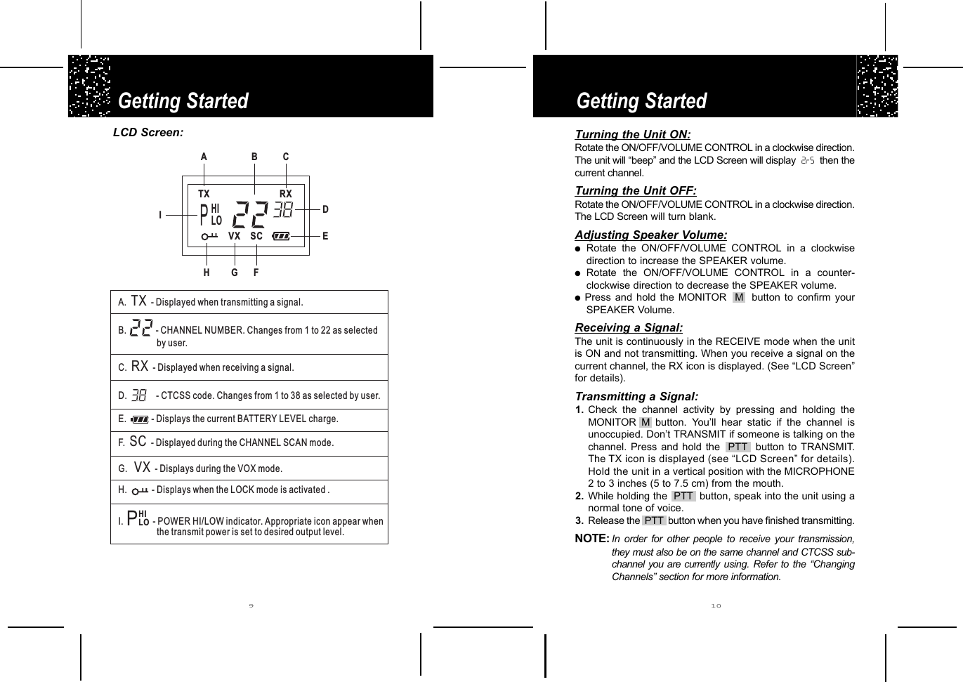
Lionda Technology Co 2730LD03 FRS & GMRS User Manual 2730 LD manu

Lionda Technology Co Ltd FRS & GMRS 2730 LD manu

users manual

VXTX RXSCModeCallGMRS/FRSPHILOCOMMUNICATORMODEL 2730OWNER’S MANUALAND OPERATING INSTRUCTIONSPLEASE READTHIS OWNERSMANUAL CAREFULLYBEFORE USE.KEEP FOR YOURREFERENCE.Made in ChinaLDRead this Owner’s Manual first toreceive the best performance from theCOMMUNICATOR.Operation on GMRS frequenciesrequires a license from the FederalCommunications Commission (FCC)Website - http://wireless.fcc.gov/prs/genmbl.htmlTel.: 1-800-418-3676FOR “GETTING STARTED” INFORMATION,PLEASE SEE INSTALLATION INSTRUCTIONS ON PAGE 7ORYOUR SEPARATE QUICK START GUIDE.© 2002 BellSouth CorporationVisit Us on the Web:www.uselectronics.info
ContentsSpecial FeaturesCongratulations on your selection of a quality BellSouth Product.With proper care and adherence to the set-up and user instructionsin this Owner’s Manual, this unit will provide you with yearsof trouble-free service.BellSouth is committed to providing quality products that fit yourneeds. We would like to have any comments or suggestions youmight have on this product. You may mail your comments to:U.S. Electronics105 Madison AvenueNew York, NY 10016PRODUCT DESCRIPTIONThe COMMUNICATOR is the newest generation in personal two-waycommunications. The COMMUNICATOR operates in a license-freeradio band on the FRS channels 8 - 14 (no FCC license is neededfor its operation), and on licensed GMRS/FRS channels 1 - 7, andGMRS channels 15 - 22 (see page 22 regarding licensinginformation).The COMMUNICATOR is a lightweight, compact two-waycommunication device that can be used to communicate with familyor friends at parks, shopping malls, sporting events, concerts -- anyindoor or outdoor activity!The COMMUNICATOR is compatible with other brands utilizing thesame FRS frequency band (operating in the frequency range from462.5625 MHz to 467.7125 MHz) or same GMRS frequency band(operating in 462.5750 MHz to 462.7250 MHz).  The  COMMUNICATOR has 22 CHANNELS, including 7 FRSchannels, 7 GMRS/FRS channels, and 8 GMRS channels (Fordetails, refer to page 15 CHANNEL TABLE.).Other features include ELECTRONIC VOLUME CONTROL andBATTERY SAVE CIRCUITRY.Please read this Owner's Manual carefully to get the most out ofyour GMRS/FRS COMMUNICATOR. NOTE: The maximum transmission range will vary depending onterrain and environment. Range will be greater in openfields, while range is shorter within and around buildings orlarge structures.This unit may not ensure privacy of communication.     PreparationCOMMUNICATOR Controls - Location & Function................... 3FCC Notice................................................................................ 5Getting StartedRemoving the BELT CLIP......................................................... 7Installing the BELT CLIP........................................................... 7Battery Installation..................................................................... 8LCD Screen............................................................................... 9Turning the Unit ON...................................................................10Turning the Unit OFF..................................................................10Adjusting Speaker Volume.........................................................10Receiving a Signal..................................................................... 10Transmitting a Signal................................................................. 10OperationChanging Channels................................................................... 11Monitor....................................................................................... 11MODE/BUTTON LOCK Button (FUNCTION EDITING)............ 11Changing the CTCSS Sub-channels......................................... 12VOX Selection............................................................................12TRANSMIT POWER SELECTION Mode.................................. 13CHANNEL SCAN.......................................................................13Sending Call Tones.................................................................... 14Battery Level Indicator............................................................... 14Battery Charge Indication.......................................................... 14Connecting an Adapter.............................................................. 15Accessory Connection............................................................... 15Other InformationSpecifications............................................................................. 15Channel Table............................................................................ 16Troubleshooting......................................................................... 17Care and Maintenance...............................................................18Warranty..................................................................................... 20Licensing Information ................................................................22
VXTX RXSCModeCallGMRS/FRSPHILOCOMMUNICATOR ControlsCOMMUNICATOR Controls3 431245678910111213141617151. ANTENNA (Pgs. 6, 18, 19) 2. BELT CLIP (LOCATED ON THE REAR) (Pgs. 6-8) 3. LCD (Liquid Crystal Display) Screen: Displays currentchannel selection and other radio status symbols. (Pgs. 9-13, 17)4. PTT  (PUSH TO TALK) button - Press to make a call.(Pgs. 10-13)5. MONITOR  M  button: Press to tune in and hold ontoweak signals. (Pgs. 10, 11, 17)6. UP  ▲▲  button : Press to change channels and selectFUNCTION in every editing mode. (Pgs. 11-14, 17)7. DOWN  ▼▼  button : Press to change channels and selectFUNCTION in every editing mode. (Pgs. 11-14, 17)8. CHARGE TERMINAL (LOCATED ON THE REAR)9. BATTERY COMPARTMENT COVER LATCH (LOCATEDON THE REAR) - Secures BATTERY COMPARTMENTCOVER. (Pg. 8)10. BATTERY COMPARTMENT (LOCATED ON THE REAR)- Houses four (4) 1.5V “AAA” alkaline or Ni-MH recharge-able batteries (not included with the package). (Pgs. 8, 19)11. SPEAKER (Pg. 10)12. MIC: MICROPHONE. (Pgs. 10, 17, 19)  13. CHARGE JACK (Pg. 15)14.  CALL  button - Press to transmit CALL Tones. (Pg. 14)15. MODE /BUTTON LOCK button - Press to shift intoFUNCTION EDITING mode.  Press and hold for 5 secondsto LOCK the buttons. (Pgs. 11-14, 17)16. ON/OFF/VOLUME CONTROL - Rotate to turn your unitON/OFF and to adjust the VOLUME CONTROL level.(Pgs. 8, 10)17. EAR (EARPHONE)/MIC(MICROPHONE) JACK (Pg. 15)
FCC NoticeFCC Notice5 6Warning: Changes or modifications to this unit notexpressly approved by the party responsible forcompliance could void the user’s authority to operate theequipment.Note: This equipment has been tested and found to complywith the limits for a Class B digital device, pursuant to Part 15of the FCC Rules. These limits are designed to providereasonable protection against harmful interference in aresidential installation. This equipment generates, usesand can radiate radio frequency energy and, if notinstalled and used in accordance with the instructions,may cause harmful interference to radio communications.However, there is no guarantee that interference will not occurin a particular installation. If this equipment does causeharmful interference to radio or television reception, whichcan be determined by turning the equipment off and on, theuser is encouraged to try to correct the interference by one ormore of the following measures:●Reorient or relocate the receiving antenna.●Increase the separation between the equipment andreceiver.●Connect the equipment into an outlet on a circuit differentfrom that to which the receiver is connected.●Consult the dealer or an experienced radio/TV technicianfor help.Safety Information:Your wireless hand-held portable transceiver contains alow power transmitter. When the Push-to-Talk (PTT) buttonis pushed it sends out radio frequency (RF) signals. InAugust 1996, the Federal Communications Commissions(FCC) adopted RF exposure guidelines with safety levelsfor hand-held wireless devices.Important: To maintain compliance with the FCC’s RFexposure guidelines, hold the transmitter and ANTENNAat least 2 inches (5 centimeters) from your face and speakin a normal voice, with the ANTENNA pointed up and awayfrom the face. If you wear the handset on your body whileusing the headset accessory, use only the supplied BELTCLIP for this product and when transmitting, take it out ofthe belt to ensure that the ANTENNA is at least 2 inches(5 centimeters) from your body.Use only the supplied ANTENNA. Unauthorized antennas,modifications, or attachments could damage the transmitterand may violate FCC regulations.  This device complies with Part 15 of the FCC Rules.Operation is subject to the following two conditions: (1) thisdevice may not cause harmful interference, and (2) thisdevice must accept any interference received, includinginterference that may cause undesired operation.
AAAAAAAAAAAARemoving the BELT CLIP:1. Pull the BELT CLIP LATCH away from the unit.2. While pulling the BELT CLIP LATCH, push up on the BELTCLIP to remove it from the unit, as shown in Figure 1.Installing the BELT CLIP:1. Slide the BELT CLIP into the BELT CLIP SLOT as shownin Figure 2.2. A “click” indicates the BELT CLIP is locked into position.Getting StartedGetting Started7 8Carefully remove your COMMUNICATOR from its BlisterPack. If there is any visible damage, do not attempt tooperate this COMMUNICATOR. Return it to the place ofpurchase.Figure 1 Figure 2Battery Installation:1. Remove the BELT CLIP. (Refer to “Removing the Belt Clip”section.)2. Remove the BATTERY COMPARTMENT COVER from theBATTERY COMPARTMENT.  See Figure 3.3. Install 4 x 1.5V “AAA” alkaline batteries or Ni-MHrechargeable batteries (not included) as shown.4. Reinstall the BATTERY COMPARTMENT COVER andlock the BATTERY COMPARTMENT COVER LATCH intoposition. (Refer to “Installing the Belt Clip” section)The COMMUNICATOR has a built in POWERSAVER feature for maximum battery life. But whenthe COMMUNICATOR is not being used, conservebattery power by rotating the ON/OFF/VOLUMECONTROL to OFF. Remove the batteries if the unitwill not be used for a long period of time.Figure 3 Figure 4
Getting StartedGetting Started910LCD Screen:VXTX RXSCA.B.C. - Displayed when receiving a signal.D.E.TR-F.G.H. - DXXSCVX- Displayed when transmitting a signal.- Displays during the VOX mode.- CHANNEL NUMBER. Changes from 1 to 22 as selectedby user.- CTCSS code. Changes from 1 to 38 as selected by user.Displays the current BATTERY LEVEL charge.- Displayed during the CHANNEL SCAN mode.isplays when the LOCK mode is activated .I. - POWER HI/LOW indicator. Appropriate icon appear whenthe transmit power is set to desired output level.1438ACBDEFGHPHILOIPHILOTurning the Unit ON:Rotate the ON/OFF/VOLUME CONTROL in a clockwise direction.The unit will “beep” and the LCD Screen will display  2rS then thecurrent channel.Turning the Unit OFF:Rotate the ON/OFF/VOLUME CONTROL in a clockwise direction.The LCD Screen will turn blank.Adjusting Speaker Volume:●Rotate the ON/OFF/VOLUME CONTROL in a clockwisedirection to increase the SPEAKER volume.●Rotate the ON/OFF/VOLUME CONTROL in a counter-clockwise direction to decrease the SPEAKER volume.●Press and hold the MONITOR  M  button to confirm yourSPEAKER Volume.Receiving a Signal:The unit is continuously in the RECEIVE mode when the unitis ON and not transmitting. When you receive a signal on thecurrent channel, the RX icon is displayed. (See “LCD Screen”for details). Transmitting a Signal:1. Check the channel activity by pressing and holding theMONITOR M button. You’ll hear static if the channel isunoccupied. Don’t TRANSMIT if someone is talking on thechannel. Press and hold the  PTT  button to TRANSMIT.The TX icon is displayed (see “LCD Screen” for details).Hold the unit in a vertical position with the MICROPHONE2 to 3 inches (5 to 7.5 cm) from the mouth.2. While holding the  PTT  button, speak into the unit using anormal tone of voice.3. Release the  PTT  button when you have finished transmitting.NOTE: In order for other people to receive your transmission,they must also be on the same channel and CTCSS sub-channel you are currently using. Refer to the “ChangingChannels” section for more information.
Operation Operation 11 12Changing Channels:The unit has 22 channels that include 7 FRS channels and 8GMRS channels. In addition, channels 1 - 7 are shared GMRS/FRS channels. ●  Press the UP  ▲▲button to move to a higher channel.●Press the DOWN ▼▼    button to move to a lower channel.●  The channel changes from 1 to 22, or from 22 to 1.NOTE:  Refer to the “Channel Table” section of this Owner’sManual for detailed frequency listings. Monitor:You can use the  MONITOR  feature to check for weaker signalsin the current channel.●Press the MONITOR  M  button for normal monitoring.●Press and hold the MONITOR  M  button until it "beeps"for continuous monitoring.MODE/BUTTON LOCK Button (FUNCTION EDITING):1. Depress the  MODE  button momentarily;●Press the button briefly  to enter into the FUNCTION EDITmodes in due order. CTCSS/VOX/POWER (HI/LOW) mode.NOTE: In the current FUNCTION EDIT mode, press the  PTT  button  to return to the NORMAL mode after making yourselection. In the FUNCTION EDIT mode, press the MODE  button again to shift from the current option in each submenu to the next option.2.Press and hold the  MODE button for 5 seconds to activateor deactivate the BUTTON LOCK mode. The BUTTONLOCK icon is displayed on the LCD Screen.NOTE: Channel Change Operations are disabled during BUTTON LOCK mode.   Press and  hold  the   MODE   button again to deactivate BUTTON LOCK mode.Changing the CTCSS Sub-channels:The COMMUNICATOR has 38 available CTCSS sub-channels. To change channels:1. Press the  MODE  button once, the CTCSS sub-channel 0will flash on the LCD Screen.2. While the CTCSS sub-channel is flashing:●Press the UP  ▲▲    button to move to a higher sub-channel.●Press the DOWN  ▼▼    button to move to a lower sub-channel.●The sub-channel changes from 0 to 38, or from 38 to 0.3. Press  PTT  button to confirm your selection and return to theNORMAL mode.4. To confirm and shift to the next option, press the  MODEbutton.NOTE: To communicate with other COMMUNICATOR units,both units must be switched to the same channel andsub-channel.VOX Selection:The COMMUNICATOR is capable of voice activated (VOX) transmission. In VOX mode, the radio will transmit a signal only when it is activated by your voice or other sound around you. VOX operation is not recommended if you plan to use your radio in a noisy or windy environment.1. Press the  MODE button twice, the VX icon will flash on theLCD Screen.2. Press the UP  ▲▲    button to turn the VOX feature ON, or pressthe DOWN ▼▼    button to turn the VOX feature OFF.3. In the VOX mode, the VX icon will be displayed.4. To confirm your selection and return to the NORMAL mode,press the  PTT  button.5. To confirm and shift to the next option, press the  MODE  button.NOTE: To save power, the unit will not turn ON the LCD Screenlight when in the VOX mode.
OperationOperation 13 14TRANSMIT POWER SELECTION Mode:This feature permits selection of the transmitting power level to high (3.0 watts) or low (0.5 watt). When using low power the unitwill have a lower transmit range but battery life will be increased.To access the TRANSMITTER POWER SELECTION function:1. Press the   MODE button 3 times,  The  P (POWER)   icon willflash on the LCD Screen.2. While the  P (POWER)  icon is flashing:●   Press the UP  ▲▲    button to select the HI POWER level.●   Press the DOWN ▼▼    button to select the LO POWER level.3. Press the  PTT  button to confirm your selection and return tothe NORMAL mode.4. To confirm and shift to the next option, press the  MODE  button.NOTE: This COMMUNICATOR unit allows you to select the P(POWER) level from high (HI) to low (LO) when usingchannels 1 through 7 and 15 through 22 only, channels 8through 14 are automatically set to power low (LO) sincethe power level is only 0.5 watt.CHANNEL SCAN: CHANNEL SCAN performs searches for active signals in anendless loop from 1 to 22.1. At the same time, press and release the  MODE  buttonand the UP ▲▲    or DOWN ▼▼    button together to activateCHANNEL SCAN. The channel number on the LCDScreen changes rapidly until an active signal is detected.2. When an active signal (one of 22 channels) is detected,CHANNEL SCAN pauses keeping the active signalbroadcasted.3. Press the  PTT  button to communicate through the active signal channel and CHANNEL SCAN is deactivated.●If the active signal is the original default channel (e.g.CH-5), when the  PTT  button is pressed, channel (CH-5) will remain the default channel.●  If the active signal is not the original default channel(e.g. CH-1), after the  PTT  button is pressed, the defaultchannel (e.g. CH-5) will automatically change to channel(CH-1).4. When an active signal (one of 22 channels) is detected, butanother channel is desired, press the UP ▲▲    or DOWN ▼▼button to bypass the current channel and continue tosearch for another active channel.5. Press the  MODE  button to deactivate CHANNEL SCANmode.NOTE: This COMMUNICATOR unit allows you tocommunicate with standard FRS models by usingchannels 1 through 14.Sending Call Tones:You can use CALL TONES to alert the other user when youare attempting to contact them. You can also use CALLTONES to signal the beginning or the end of a transmission.1. Press and release the  CALL  button, the red TX LEDindicator will light up and the CALL TONE continues for 3seconds.2. Your Call Tones will transmit to nearby receivers set to thesame channel.Battery Level Indicator:1. The BATTERY LEVEL is indicated by the number of squarespresent inside the BATTERY icon on the LCD Screen.2. When the BATTERY LEVEL is low, the BATTERY icon willflash to indicate that the batteries need to be replaced.3. Do not charge this unit using an AC/DC adapter withregular “AAA” alkaline batteries installed. Only use anoptional AC/DC adapter with “AAA” Ni-MH rechargeablebatteries (not included).Battery Charge Indication:During BATTERY CHARGE mode, the BATTERY indicator willkeep scrolling.NOTE: Please ensure that the unit is turned OFFduring BATTERY CHARGE mode.
Specifications:Channel Table Specifications 15 16*  All 15 Channel GMRS units including BellSouth use the same channels.NOTE: For your convenience it is suggested that you use Channels 1thru 14. Operation of this model on GMRS frequencies(Channels 1 thru 7 & 15 thru 22) requires a license from theFederal Communications Commission (FCC).Use the following channel conversion chart to communicateon the same frequency with other GMRS and GMRS/FRS models.BellSouth22 Channel ModelsOther Brands22 Channel ModelsAll Brands*15 Channel ModelsChannels 1-7 Channels 1-7 Channels 1-7Channels 8-14 Channels 8-14 N/AChannel 15 Channel 16 Channel 8Channel 16 Channel 18 Channel 9Channel 17 Channel 20 Channel 10Channel 18 Channel 15 Channel 11Channel 19 Channel 17 Channel 12Channel 20 Channel 19 Channel 13Channel 21 Channel 21 Channel 14Channel 22 Channel 22 Channel 15Note:  Channels 1 to 14 are shared with the FRS radio channels.Channels 15 through 22 are exclusively for GMRS radios. The maximumtransmission range will vary depending on terrain and environment.Connecting an Adapter:In the event you wish to use the unit with rechargeable batteries(not included) you will be required to use an AC/DC adapter -Input 120 VAC 60 Hz - Output 7.5 VDC 150mA (not included).●Insert 4  "AAA" Ni-MH rechargeable batteries (not included).●Turn the unit OFF.●Plug the adapter into the wall and insert the round end intothe CHARGER JACK at the side of the unit.●Unplug the adapter. Turn the unit ON. The BATTERYLEVEL INDICATOR on the LCD Screen will display thenew BATTERY LEVEL.CAUTION: Your COMMUNICATOR must have rechargeable“AAA” batteries installed before using the externalAC/DC adapter.You may order the adapter and or batteriesby calling 1-800-828-5208.NOTE: It takes approximately 5 to 6 hours to fully chargethe batteries if they are at their lowest level.Accessory Connection:The COMMUNICATOR is designed to be used with accessories(Earphone, Microphone, etc.).22 Channels38 for each Channel138 mW(GMRS )/7             5 mW(FRS)About 7 Miles (GMRS) / 2 Miles (FRS)Channels AvailableCTCSS Sub-channelERP (TX)RangeChannel TablePOWER(mW)POWER(mW)FREQUENCY(MHz)15467.6625467.6875467.712516171819202122CHANNELNUMBERCHANNELNUMBER123456789101112131411411411411411411411413813813813813813813813875757575757575FREQUENCY(MHz)467.5625467.5875467.6125467.6375462.5625462.5875462.6125462.6375462.6625462.6875462.7125462.5750462.6250462.6750462.5500462.6000462.6500462.7000462.7250Channel Conversion Chart
Care and  Maintenance Troubleshooting 17 18CAUTION !Damaged ANTENNA:Do not use any COMMUNICATOR that has a damaged ANTENNA. If adamaged ANTENNA comes in contact with the skin, a minor burn mayresult. Batteries:All batteries can cause property damage and/or bodily injury such asburns if conductive material such as jewelry, keys, or beaded chainstouches exposed terminals. The material may complete an electricalcircuit (short circuit) and become quite hot. Exercise care in handlingany charged battery, particularly when placing it inside a pocket, purse,or other container with metal objects.WARNING !For Vehicles with an Air Bag:Do not place your COMMUNICATOR in  the area over an air bag or inthe air bag deployment area. Air bags inflate with great force. If aCOMMUNICATOR is placed in the air bag deployment area and the airbag inflates, the COMMUNICATOR may be propelled with great forceand cause serious injury to the occupants of vehicle.Potentially Explosive Atmospheres:Turn your COMMUNICATOR OFF when in any area with a potentiallyexplosive atmosphere, unless it is a type specifically qualified for suchuse (for example, Factory Mutual Approved). Sparks in such areas couldcause an explosion or fire resulting in bodily injury or even death.Batteries:Do not replace or charge batteries in a potentially explosive atmosphere.Contact sparking may occur while installing or removing batteries andcause an explosion. Blasting Caps and Areas:To avoid possible interference with blasting operations, turn yourCOMMUNICATOR OFF near electrical blasting caps or in a “blastingarea” or in areas posted: “Turn off two-way radio”. Obey all signs andinstructions.NOTE: Areas with potentially explosive atmospheres are often, butnot always, clearly marked. They include fueling areas such as belowdeck on boats; fuel or chemical transfer or storage facilities; areaswhere the air contains chemicals or particles, such as grain, dust, ormetal powders; and any other area where you would normally beadvised to turn off your vehicle engine.SYMPTOMNo power. Reception is weak.Cannot changechannels.Range is limited.Sound distortionproblems.SOLUTION●Check batteries. Ensure that the batteries areinstalled properly.●The batteries may be weak.●Replace old batteries with four (4) new 1.5V“AAA”  alkaline batteries or Ni-MHrechargeable batteries.●Press the UP  ▲▲    button to increase VOLUME●The receiving signal may be weak and/or out ofrange.●If this happens, press the MONITOR M  button.●To change channels, press the  MODE  buttonuntil the channel number flashes on the LCDScreen.●Press the UP ▲▲    or DOWN ▼▼    buttons tochange channels.●Batteries may be weak.●  BUTTON LOCK mode must be deactivated.●BATTERIES may be weak.●Replace with new batteries if the BATTERYLEVEL indicator is low.●The maximum range will vary depending onterrain and environment.●Open fields provide the maximum range, whilesteel/concrete structures, heavy foliage, anduse in buildings and in vehicles may limit therange significantly.●Wearing the radio close to the body, such as ina pocket or on a belt, will decrease range;change the location of the radio.●If you are transmitting, speak in a normaltone of voice, 2 to 3 inches away from theMICROPHONE.●If you are receiving, lower the volume to acomfortable level.●Radios too close. Radios must be at least 5 feetapart; increase your distance.●Radios too far apart. Obstacles interfere withtransmission. Talk range is from 2 to 7 miles inclear unobstructed conditions.
Warranty Care and  Maintenance2019BellSouth Products One-Year Limited WarrantyThis limited warranty sets forth all BellSouth Products responsibilitiesregarding your COMMUNICATOR. There are no other expressed orimplied warranties from BellSouth Products.Warranty Service ProvidedIf you purchased the COMMUNICATOR unit new from a retail vendor,BellSouth Products warrants the equipment against defects in materialand workmanship for a period of one (1) year from the original date ofpurchase. This warranty is in lieu of all other express warranties. Thiswarranty begins when you purchase the COMMUNICATOR unit andcontinues for one (1) year unless you sell or rent the unit, in which casethe warranty stops.BellSouth Products disclaims any implied warranty, including thewarranty of merchantability and the warranty of fitness for a particularpurpose, as of the date of one year from your original purchase of theCOMMUNICATOR unit. BellSouth Products assumes no responsibilityfor any special, incidental, or consequential damages.This warranty gives you specific legal rights and you may have otherrights  which vary from state to state. Some states do not allow theexclusion or limitations of special, incidental or consequential damagesor limitations on how long a warranty lasts, so the above exclusionor limitation may not apply to you.Warranty Service Not ProvidedThis warranty does not cover damage resulting from accident, misuse,abuse, improper installation or operation, lack of reasonable care,unauthorized modification, or the affixing of any attachment not providedby BellSouth Products with the COMMUNICATOR unit, and/or loss ofparts. This warranty is voided in the event any unauthorized personopens, alters, or repairs the unit.All  BellSouth equipment being returned for repair must be suitablypackaged.BellSouth Products does not warrant that this equipment is compatiblewith the type of accessory of any particular communicator company orthe services provided by it.Care and  MaintenanceTo clean the unit, wipe with a soft cloth dampened with water. Don’t usecleaner or solvents on the unit; they can harm the case and leak inside,causing permanent damage. Battery contacts may be wiped with a dry,lint-free cloth.If the unit gets wet, turn it OFF and remove the batteries immediately.Dry the BATTERY COMPARTMENT with a soft cloth to minimize potentialwater damage. Leave the cover off the BATTERY COMPARTMENTovernight or until completely dry. Do not use the unit until completely dry.  Exposure to Radio Frequency Energy:The design of your COMMUNICATOR, which generates radio frequency(RF) electromagnetic energy (EME), complies with the following nationaland international standards and guidelines.The Relevant Guidelines and Standard Are:●FCC Report and Order FCC 96-326 (August, 1996) ●American National Standards Institute (C95-1-1992)●National Council on Radiation Protection and Measurements (NCRP-1986)●International Commission on Non-lonizing Radiation Protection(ICNRP -1986)To ensure optimal unit performance and to ensure that exposure to RFenergy is within the guidelines in the above standards, the followingoperating procedures should be observed:For Portable Two-way Communicators:●When transmitting with a COMMUNICATOR, hold the COMMUNICATORin a vertical position with its MICROPHONE 1 to 2 inches (2.5 to 5.0cm) away from your mouth. Keep the ANTENNA at least 2 inches (5cm) from your head and body.    ●If you wear a COMMUNICATOR on  your body, ensure that theANTENNA is at least two inches (5 cm) from your body whentransmitting.Electromagnetic Interference/Compatibility:Nearly every electronic device is susceptible to electromagneticinterference (EMI) if inadequately shielded, designed, or otherwiseconfigured for electromagnetic compatibility.●Turn your unit OFF in any facilities where posted notices instruct youto do so. Hospitals or health care facilities may be using equipmentthat is sensitive to external RF energy.●Turn your unit OFF when on board an aircraft when instructed to doso. Any use of the unit must be in accordance with airline regulationsor crew instructions.
To Obtain Warranty Service• Provide proof of the date of purchase within the package.• Prepay all shipping costs to the authorized service center.• Include a return shipping address within the package.Please retain your sales receipt, the carton, the packing materials, andthe printed material. The original carton is the best shipping containerfor the COMMUNICATOR unit should you have to return it.For your reference:Model NumberDate of PurchaseName of DealerCustomer Service Telephone Number:1-800-864-2199Warranty 2221Licensing Information What To Do for Warranty ServiceDuring the first thirty (30) days, a defective product is eligible for over-the-counter exchange at the retailer from whom it was purchased. Afterthirty (30) days, the defective product should be returned to theauthorized service center. The shipping address of the authorizedservice center is:U.S. Electronics CONSUMER CENTERC/O Southern Bonded Warehouse7137 Southlake ParkwayMorrow, GA 30260Website - www.uselectronics.infoYour unit will be repaired or replaced if examination by the service centerdetermines the unit is defective.A COMMUNICATOR unit received damaged as a result of shipping willrequire you to file a claim with the carrier to cover repair costs.A COMMUNICATOR unit received with missing parts or with damagedue to abuse, inadequate packing, or some other noncompliance withthis limited warranty will be returned to you C.O.D., freight collect.NOTE: A COMMUNICATOR unit received which was not made forBellSouth Products or which is not defective as determinedby our test procedures will not be repaired and will be returnedto you C.O.D., freight collect.FCC Licensing InformationChannels 1 thru 7 transmit on GMRS/FRS frequencies.Channels 8 thru 14 transmit on FRS frequencies.Channels 15 thru 22 transmit on GMRS frequencies.Operation on GMRS/FRS and GMRS frequencies requires alicense from the Federal Communications Commission (FCC).Information regarding an application for your license can beobtained as follows if you intend to use the GMRS channels:Website - http://wireless.fcc.gov/prs/genmbl.htmlTel.:  1-800-418-3676GMRS Licensing Information Before any station transmits on any channel authorized in theGMRS from any point within or over the territorial limits of any areawhere radio services are regulated by the FCC, the responsibleparty must obtain a license for a GMRS system. An individual 18years of age or older, who is not a representative of a foreigngovernment, is eligible to apply for a GMRS system license.  Application for a GMRS system license is made on FCC Form 605and you can obtain a copy from the FCC's Web site:http://www.fcc.gov/formpage.html or by calling the FCC's FormsDistribution Center 1-800-418-FORM (3676), or from the fax-on-demand by dialing (202) 418-0177. There is a filing fee. For information on fees, see the FCC's Website:  http://wireless.fcc.gov/csinfo/feeinfo.html

Navigation menu