Lionel BASE2 Model Train Control Transmitter User Manual manual rev 9 1
Lionel L.L.C. Model Train Control Transmitter manual rev 9 1
UserManual.wiki
>
Lionel
>
BASE2 User Manual
>
users manual
Contents
1.
users manual
2.
users manual revised page
users manual
Navigation menu
Upload a User Manual
Namespaces
Wiki Guide
HTML
PDF
Info
Views
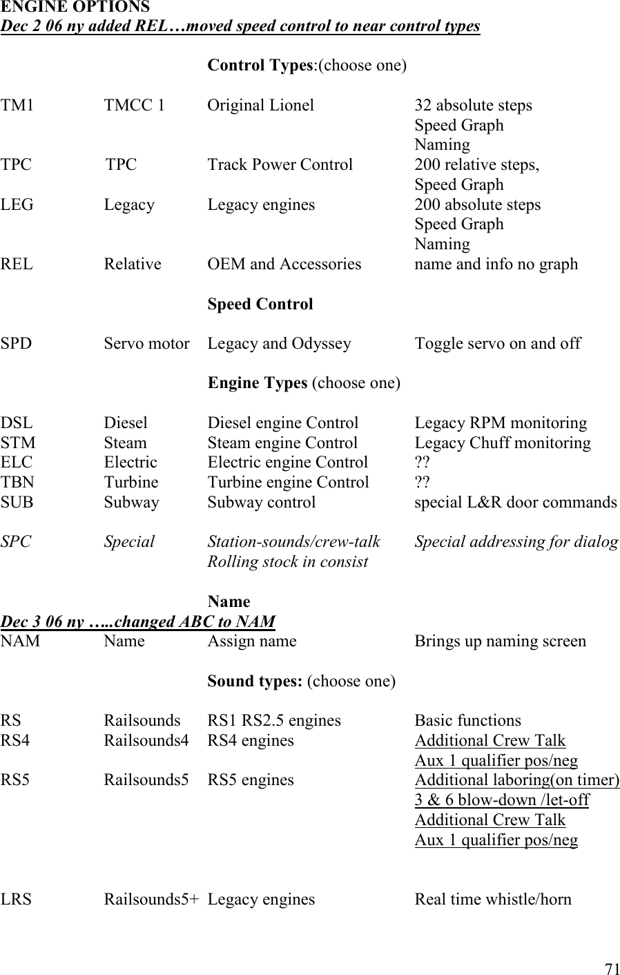
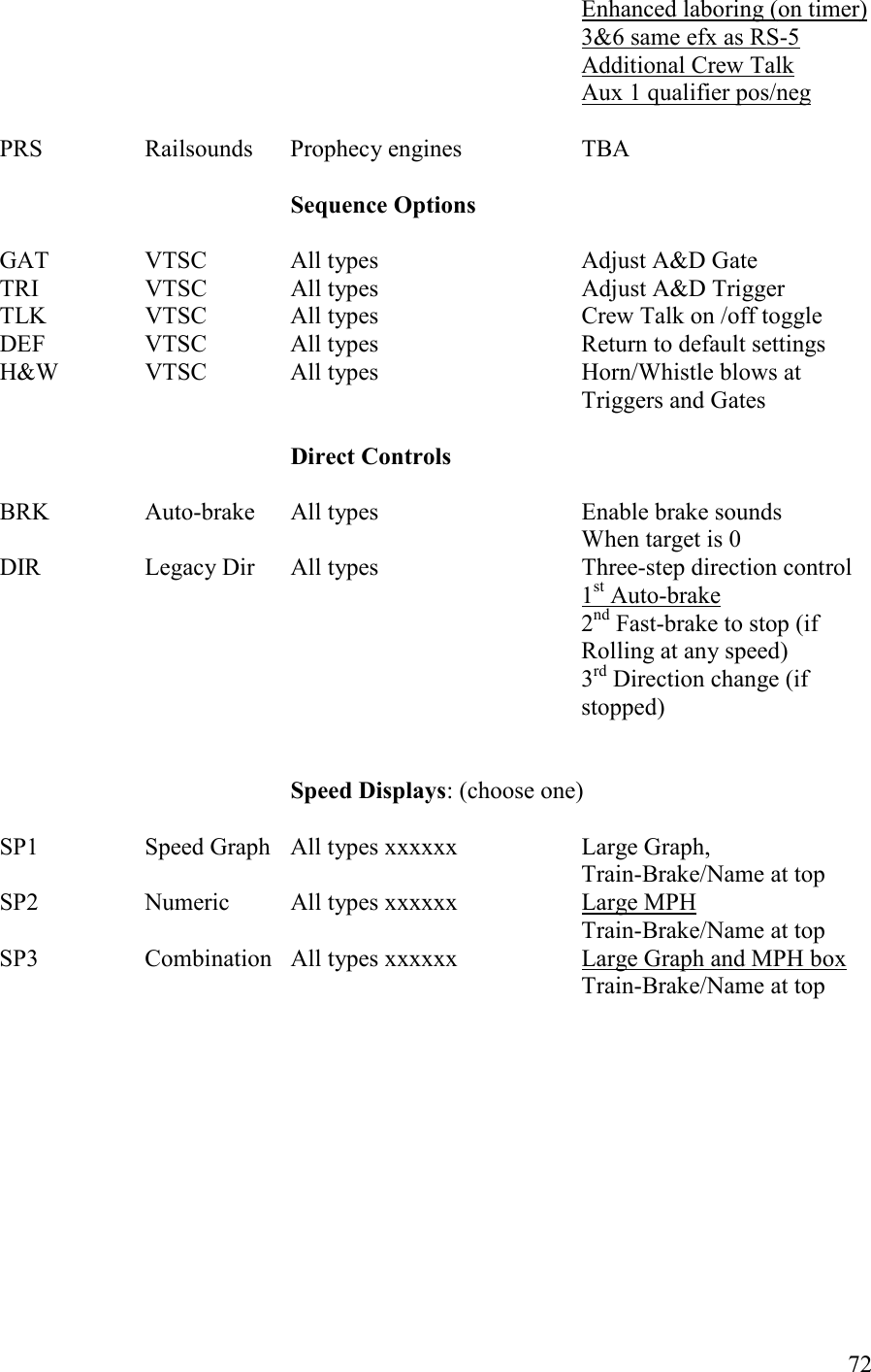
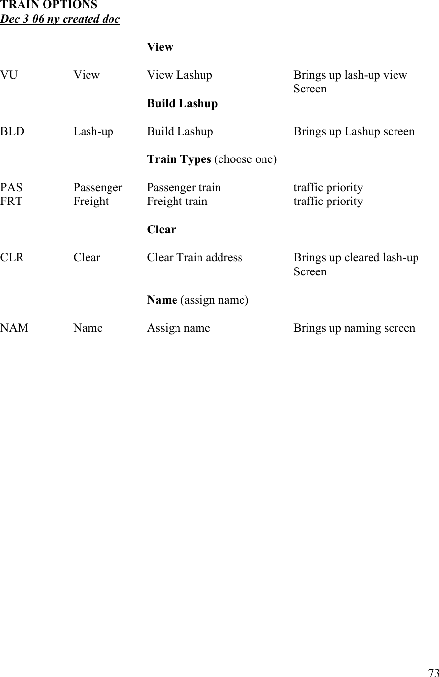
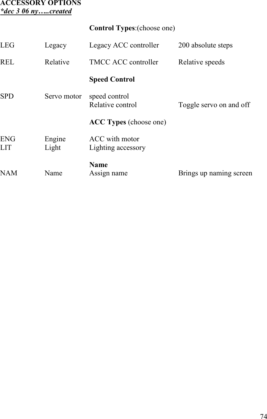
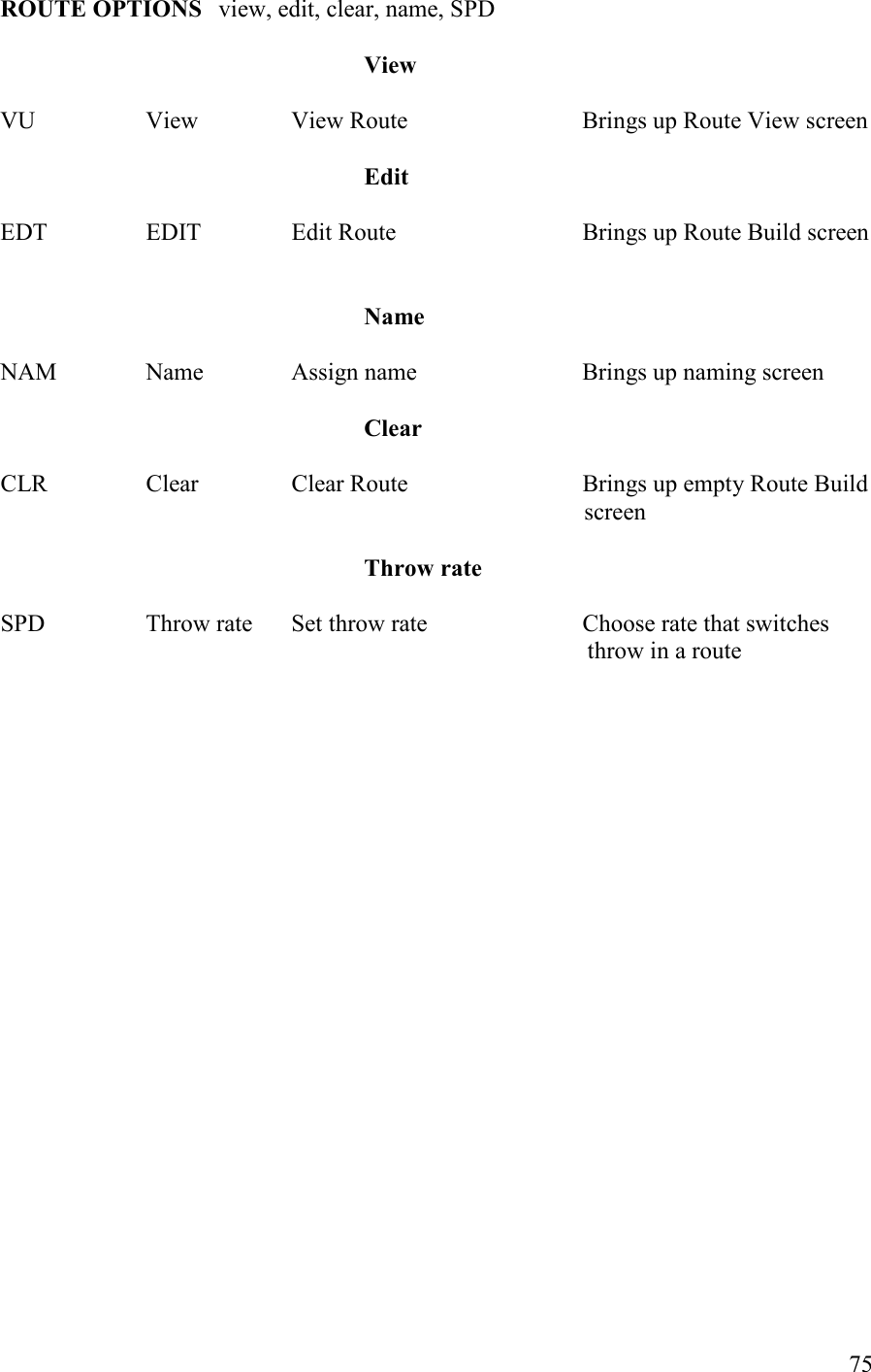
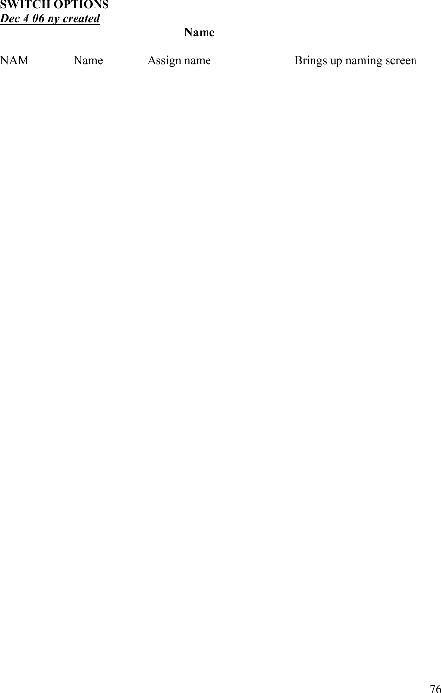
User Manual
Discussion / Help
Navigation