Lionel CAB2 Model Train Control Transmitter User Manual manual rev 9 1
Lionel L.L.C. Model Train Control Transmitter manual rev 9 1
Lionel >
users manual
1
LIOEL
LEGACY

2
Dec 12 06 ny changes to reflect new order and doc changes
Dec 16 06 ny changes to reflect new order and doc changes
WELCOME
STARTIG OUT
EGIE ID #
Universal address
MEMORY MODULE DOWLOAD TO THE LEGACY COTROL SYSTEM
TMCCengine and retrofit engines
Custom Read/Write Memory Modules
IFO
Entering engine options
GIVIG YOUR EGIE A AME
aming procedure
CTC MEU
SELECT
SCROLL
TRADITIOAL OPERATIG SECTIO
Addressing with the Lionel Legacy Control System
Switch
Accessory
Route
Train
Engine
SPEED GRAPH may move to new position
DIRECT COTROL SECTIO
Official RR speed control
Touch-screen
Record
Feedback
SEQUECED COTROL OPERATIG SECTIO
LEGACY VELOCITY THROTTLE
MOMETUM
LEGACY SEQUECED COTROL
3
Arrival and departure sequence
Fine tuning velocity throttle sequences
Sequence options
TABLE OF OPTIOS
Engine options
Train options
Accessory options
Route options
Switch options
Direct control options
Sequence control options
Base options
Remote options
OTES
WORK AREA…HARD HAT REQUIRED

4
WELCOME
Dec 6 06 ny changes to text
Dec 13 06 ny changes to text
Welcome to the world of Lionel Legacy Command Control.
Congratulations on your purchase of this new operating system. It is the
system others will be judged by in the years to come.
The Lionel Legacy Control System controls every product made over the
history of LIONEL, 107 years at this date, in a way that is superior to any
control available. It is truly the Lionel Legacy Control System.
Contemporary control systems for all model train gauges have been
developed over the years to enhance your experience with electric trains.
Command control is the most advanced way to control a layout and many
operators are using command control systems on their layouts today.
This system is different. It integrates all of the new effects that Lionel has
made so popular. Sounds, smoke effects, servo-controlled speed and more
are easily accessed during the normal course of operation. The Lionel
Legacy Control System makes these features and effects available to you
in an unprecedented variety of operating possibilities.
The Lionel Legacy Control System improves operation of every LIONEL
ever made, starting in 1900. Enhanced speed resolution brings new realism
to our pre-war and post-war products, whether they are the originals that
made history, or the TMCC equipped engines and operating cars that
celebrated our heritage by bringing the latest technology to these great
products. This control system is another milestone in LIONEL history.
The Lionel Legacy Control System improves all of the interfaces operators
have become accustomed to using with modern command control trains.
The new real-time “quilling” Whistle-Horn control is a great example. In
place of our pioneering original method, pressing a button and triggering
an onboard sound device, or hearing a pre-recorded sound from an
electronic source, the Lionel Legacy Control System pioneers new control
of the warning sounds through a spring-loaded lever that makes it possible
for you to “play” the whistle just like real engineers did in the hey-day of
steam operations. But that’s not all. You will also experience
revolutionary new ways of controlling brake, boost, bell, direction,
switches, routes and more. It is all new.
The hallmark of this new Lionel system is simplicity. Yet under the
surface is a state of the art operating system with pioneering advances that
5
have never been seen, felt, or heard before. This system makes and
supports Lionel history.
One interface, the throttle, has been re-invented to provide an operating
experience that is unparalleled in model trains to this date. Just imagine
controlling all the train effects from your throttle while watching your
train and rarely having to look at the controller to find a button or read a
display!
The Lionel Legacy Control System is here! Congratulations! You are
onboard and right on time!
6
STARTIG OUT
Dec 6 06 ny changes
Dec 12 06 ny added 3 prong socket reminder.
Dec 13 06 ny added factory ID # 1 …
Here’s how to start.
Take your system out of the box, become familiar with the contents and
set it up following these instructions:
Insert diagram 1(command base connection and lights description) here
First, plug in the Command Base power cord to a three prong socket and
connect your command base to the track with the single wire included.
Check out the diagram and see if you have everything right. The lights
should be on. Remember, this system requires a three prong socket for
power.
Before you operate your new Lionel Legacy Control System equipped
engine, give your engine an ID # and set it up correctly by adding it to
your system’s roster of engines. Follow the directions that came with your
locomotive or read on in this manual.
Note that your new Lionel Legacy Control System equipped engine comes
with a factory ID # 1 and will respond to that address immediately.
7
EGIE ID #
Now, it’s time for the engine. You can start by giving your new engine a
ID#.
Insert diagram 1.5 address assignment (program run switch) here
To give your new Engine an ID#:
1 Slide the program/run switch to “Program”.
2 Power down your track.
3 Put the engine on the track.
4 Power up your track.
5 Make sure no other CABs are in use
6 Press EN
7 Enter a unique engine ID # 1 to 98 with Cab 2
Insert diagram 1.1 (assign ID#) here
8 Press SET
Insert diagram 1.2 (set button) here
9 The horn should blow, the headlight pulse, or both.
10 Take the engine off the track (optional) and
11 Slide the program/run switch back to “Run” right
away.
12 Power down your track.
13 Put the engine on the track again.
14 Power up your track.
15 You are ready to operate.
UIVERSAL ADDRESS ID # 99
If you would like to run all the trains on your layout at once with one
address, just address ID # 99 to start up all your engines at once. Every
engine will respond to ID # 99. It is not necessary to program the engine to
ID # 99.
All engines are factory programmed to respond to ID #1 or ID # 99 at the
factory. You can change the ID # 1 but not the ID # 99.
8
.
MEMORY MODULE DOWLOAD TO THE LEGACY COTROL SYSTEM
• dec 4 06 ny (saving to custom read/write memory modules added)
• dec5 06 ny changes reflecting UPLOAD and changed uploading directions to use
“save IFO” prompt
dec 12 06 ny changes to ew Lionel Legacy Control System equipped Engines
•
Now it is time to insert the memory module and load the system with all
of your new engine’s information. This is a necessary step that you only
do once.
ew Lionel Legacy Control System equipped Engines
Each Legacy engine is packaged at the factory with a unique memory
module. Make sure you locate, use and save the memory module. It will
enter all the unique information about your engine when you plug it into
the CAB 2.
Now you are ready to insert your engine’s unique memory module into
CAB 2. It will be downloaded into the system and associated with the
TMCC ID # you have entered. All other remotes will have the information
too.
9
TMCC Engines and Retrofit Engines
Custom Read/Write Memory Modules
Older TMCC engines have their Engine options entered manually. Here’s
how to save that info so you can take it with you to a new Legacy layout.
Once the info has been entered manually (see page XXX, Engine options),
address the engine, and insert a Read/Write memory module into Cab 2.
Follow the prompts to upload. Now you have saved the engine INFO into
the Memory Module.
TMCC engines do require a Read/Write memory module if you want to
take them to a new layout and would like to have the name and engine
options available to download into the new layout’s Legacy system base.
When you arrive at the new layout, pick up a CAB 2 and address your
older TMCC locomotive. Then insert the memory module into the Cab 2.
You have added all the INFO for that locomotive into the new layout’s
Legacy System.
Read/Write modules come with retrofit kits or are purchased separately.
Insert Diagram 3.7 (Insert Memory Module) here.
How to upload Engine Options to Memory modules
With your TMCC engine addressed, and Engine options manually
entered,
1 Address TMCC engine
2 Press INFO
3 Insert memory module into remote
4 Select “SAVE INFO”
When the information is uploaded (a few seconds, watch the Display
screen) you can remove the memory module from the CAB 2 and place it
in the optional TMCC 2 Legacy Roll-Top Memory Garage or another safe
place.
Diagram 3.8 of memory module inserting into CAB 2 here
10
To view the saved information about your engine at any time, just press
INFO.
Diagram 3 of display with engine name, road-number and TMCC ID#
here
Memory Garage
Store your Memory Modules in the Memory Garage
Insert Diagram 3.5 (Memory Garage), here.
The optional Memory Garage is a modular piece of the master control
panel.

11
IFO
Dec 4 06 ny changes
IFO is the where you find all of your train, engine, track, or accessory
options. These options are either downloaded from a memory module that came
with your LIOEL LEGACY product or entered manually for TMCC products.
TO ACCESS IFO:
Address train, engine, track or accessory
Press INFO.
Scroll through Options for the train, engine, track or accessory
Insert diagram 8 of IFO menu Options page here
After scrolling through, select from each of the categories in the Options
menu. Choose the description that matches your train, track, engine or
accessory. Move to the next category and choose again. Repeat until each
of the categories has a choice made to match your train, track or
accessory. This procedure only needs to be done once.
ow you have completed entering your TMCC engine’s IFO. The
Legacy system will know how to control your train, and how you want to
view it on the Display screen, whether it is LEGACY or TMCC.
12
ETERIG EGIE OPTIOS
Here’s how to do it step by step:
First, make sure you have addressed your engine by its ID#
To enter INFO:
Insert diagram 9 of a selection from engine options (control types) here
Pressing INFO will
1 Open the info display window
2 Scroll through the categories with the Rotary and
get familiar with them. Find “Engine Options”
Insert diagram 9 of a selection from engine options (control types) here
3 Enter the correct info in “Engine Options” by
a. Locating the correct EGIE OPTIO in the
center box
b. Select it by pressing the soft-key under it
c. Select one of the choices in the category
d. Move on to the next category
e. Check all the EGIE OPTIO categories and
make sure the choices are correct.
f. If a TMCC1 engine is retrofitted to LEGACY,
Choose LEGACY under Control types.
g. If a TMCC 1 engine is not retrofitted, choose
TMCC 1 under Control types.
h. If an engine is a Diesel, select Diesel under
Engine types.
i. If a sound system is RS 5, select RS5 under
Sound types
j. If an engine is an Odyssey, select Odyssey
under Speed Control.
k. Make sure you get every Engine Option right. It
will perfect the Legacy system operation of your
Velocity Throttle, Control Panel, Speed Graph
and Rail-sounds.

13
GIVIG YOUR EGIE A AME
AMIG PROCEDURE
Dec 4 06 ny created
Dec 5 06 ny changes to use “numerics” for entering number
Names can be given to Engines Routes, Trains, Accessories and Switches. Follow this
method to use the Legacy Naming feature.
Address an EN, TR, ACC, or SW
For Route, just press RTE
Press INFO
Insert display screen diagram “OPTIOS” here
If requested, Enter ID #
Scroll through Options to NAME
1 select name
Insert display screen diagram “Enter ame” here
You will see the Alpha-Numeric character choices.
1 Scroll to the first character.
2 Add the character by scrolling to it and pressing ADD
3 Add more characters
4 If using multi-words, insert a SPACE between them.
5 Delete what you want to change
6 Scroll to mistakes, delete them and replace them.
7 There is a limit of XX characters. Use abbreviations where needed.
8 When you are finished naming, Press set
9 Make sure Display prompt says SAVED.
Insert display screen diagram “Enter Road number or Lionel number” here
Follow the prompt to enter a Road number or Lionel number up to 4 digits bt
using the numerics on the touch screen.
Press set to save.

14
CTC
Dec 4 06 ny changes
Use CTC button to toggle between
1 Real Time Operation Display screen
2 Base and CAB options
Insert diagram 12 CTC toggle (two windows) here
Scroll clockwise for Base OPTIOS and counter-clockwise for CAB2 Remote
options.
CAB2 Modes of Operation
There are two modes of operating your CAB 2
They are found in the CAB2 remote options menu
Cab 1 Mode
Cab 1 mode is just like operating a CAB 1
The display will show everything a CAB1 can do.
Cab 2 Mode (default)
CAB 2 Mode provides all of the new TMCC2 Legacy features.
Insert diagram 15 mode select here
ACCESSIG CAB MODES
Press CTC
1 Scroll to counter-clockwise to CAB2 Remote
options.
2 Choose CAB 1 or CAB 2.

15
SELECT
Dec 5 06 ny changes to select here
Dec 12 06 ny punctuation changes
Insert diagram 13 select Road number or Lionel number ( box
with 4 digit number) here
1 Press “SELECT” to address a unit by its number.
2 A display window appears for you to enter the
number.
3 Enter the number in the display window.
4 Press the EN, ACC, TR or SW soft-key.
You are now ready to run your selected unit.

16
SCROLL (Rotary throttle)
Dec 5 06…… ny changes
Dec 12 06 ny changes to *route
Insert diagram 14 scroll ( 2 windows show names of 2 engines) here
Press EN, TR, ACC, *RTE, or SW.
Press Scroll
1 Scroll through the name selections
2 Locate the name
3 Press EN, TR, ACC, *RTE, or SW
4 EN, TR, ACC, or SW is now addressed
5 *RTE is thrown.
*Routes throw as soon as they are addressed.

17
TRADITIOAL OPERATIG with Cab 2
Dec 12 06 ny changes to content
Introduction
Insert diagram 15.5 CAB 2
Lionel Legacy addressing and controls for Traditional command control
operation are described in this section. This is the way your new CAB 2
and LIONEL Legacy products will operate the first time you try them.
There are a lot of new features available immediately with CAB 2.
When you leaarn to use the Options menu in the Cab 2, you will discover
that ther are many optional “advanced” methods of using the Direct
Controls. But for now the Direct Controls are default set up for basic
operation. You can access the advanced optional features in ENGINE
OPTIONS of the INFO menu
Take the time to read the following descriptions of how the CAB 2
controls work. It will be helpful. Although the signal on the track is
similar to Train-Master Command Control, the amount of commands has
been increased by many thousands, allowing for much more control of
your Lionel Railroad.

18
ADDRESSIG WITH LEGACY COTROL
Dec 5 06 ny added “Addressing” to titles
Dec 6 06 ny added “ACCESSIG (type) OPTIOS”
Dec 6 06 ny added “ADDRESSIG (type) METHODS” to titles
Dec 14 06 ny…… clarification of terms
Dec 18 06 ny…… re-ordering of instructions and new line, “ first……” added
throughout
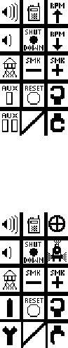
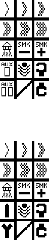
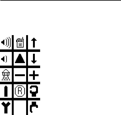
Address Keys
Address keys are used whenever you address. This section explains different
methods to address switches, accessories, routes, trains and engines. In
addition, options you can select to enable these different methods are
outlined.
Insert diagram 60 address keys 1 here
SWITCH
First, you must enter all the options in the Switch Options section of the IFO
menu.
SWITCH OPTIOS
To access Switch Options
1 Press switch
2 Enter SW ID#
3 Press INFO
View the switch options screen
Insert diagram” Switch options” here
There is one just one option, name.
SWITCH ADDRESSIG METHODS
After all of the SWITCH OPTIONS have been entered, try these SWITCH
ADDRESSING METHODS to address your Switch. If your switch’s info has not been
entered in SWITCH OPTIONS of the INFO menu, only the Traditional ID# and Toggle
methods outlined in this section will apply.
19
There are three ways to address switches
Traditional ID#
Diagram 4 of traditional addressing here
1 Press SW
2 Enter the one or two digit SW #
3 Press the THROUGH or OUT key
4 The switch will throw
5 enter a new ID #
6 throw the switch
7 repeat
ame
Insert Diagram 6 of name addressing here (name in box)
1 Press SW
2 Press SCROLL
3 Use the rotary to scroll to the desired name
4 Press SW
5 press “through” or “out”
Toggle
Insert Diagram 7 of toggle addressing here (2 diagrams with button
press and different addresses)
1 Press SW
2 Press SW again to toggle between your last two
switch addresses
3 enter another ID #
4 throw the switch
5 repeat

20
ACCESSORY
Dec 14 06 ny…… clarification of terms
First, you must enter all the options in the Accessory Options section of the IFO
menu.
ACCESSORY OPTIOS
Dec 4 06 ny….. created
Dec 5 06 ny…… added TMCC to control types
Dec 14 06 ny…… clarification of terms
To access Accessory Options
1 Press Accessory
2 Enter Accessory ID#
3 Press INFO
View the Accessory Options screen
Insert diagram “Accessory Options” here
Choose from Control type, Speed Control, ACC type, Name
Control type
Press Control Type
1 Legacy
2 TMCC
Insert diagram “Accessory Control Type” here
Speed Control
Press Speed Control (choose one)
1 Speed control
2 Relative
Insert diagram “Acc Speed Control” here
Accessory type
Press ACC Type
1 Light (toggle)
2 Motor driven accessory (toggle)
3 Momentary
Insert diagram “ACC Type” here
ame
Press Name
1 Access naming screen
Insert diagram “AME Accessory” here
21
ACCESSORY ADDRESSIG METHODS
After all of the Accessory info has been entered, try these ACCESSORY ADDRESSING
METHODS to address your Accessory. If your Accessory’s info has not been entered in
ACCESSORY OPTIONS of the INFO menu, only the Traditional and Toggle methods
outlined in this ACCESSORY ADDRESSING METHODS section will apply.
There are four ways to address accessories
Traditional ID# (see page XX)
Diagram 4 of traditional addressing here
1 Press Accessory
2 Enter the Accessory’s ID#
Lionel umber
Insert Diagram 5 of Lionel umber addressing here (4 digit Lionel
number in box)
eed diagram of old accessory and number plate
1 Press SELECT
2 Enter the Lionel number found on your accessory
3 Press Accessory
ame
Insert Diagram 6 of name addressing here (name in box)
1 Press Accessory
2 Press SCROLL
3 Use the rotary to scroll to the desired name
4 Press Accessory
Toggle
Insert Diagram 7 of toggle addressing here (2 diagrams with button
press and different addresses)
1 Press Accessory
2 Press Accessory again to toggle between your last
two Accessory addresses

22
3 Now pressing any key will activate that Accessory
Control
4 Panel in the touch-screen and activate the NAME
and other info in the Display.
ROUTE
First, you must enter all the options in the Route Options section of the IFO menu.
ROUTE OPTIOS
Dec 4 ny….. created
To access Route Options
1 Press Route
2 Press INFO
3 Enter RTE ID #
View the Route Options screen
Insert diagram “Route Options” here
Choose from view, edit, clear, name, SPD
Press View
3 View shows all the switches and Routes in a Route.
Insert diagram “View Route” here
Press Edit
3 Edit takes you to the ROUTE BUILD Screen.
4 (see ROUTE BUILD)
Insert diagram “Route Build” here
Press Clear
4 Edit takes you to empty ROUTE BUILD Screen.
Insert diagram “Route Build” here
Press Name
1 access naming screen
Insert diagram “AME Route” here
23
Press SPD
1 Adjust time between switch throws
Insert diagram “Throw Rate” here
ROUTE ADDRESSIG METHODS
After all of the ROUTE info has been entered, try these ROUTE ADDRESSING
METHODS to address your ROUTE. If your ROUTE’s info has not been entered in
ROUTE OPTIONS of the INFO menu, only the Traditional and Toggle methods
outlined in this ROUTE ADDRESSING METHODS section will apply.
There are two ways to address and throw Routes
Traditional ID#
Diagram 4 of traditional addressing here
1 Press Route
2 Enter a one or *two digit number
3 The route will throw
ame
Insert Diagram 6 of name addressing here (name in box)
1 Press Route
2 Press SCROLL
3 Use the rotary to scroll to the desired name
4 Press Route
QUICK ROUTE ADDRESS
*Customize your ROUTE addresses to suit your own layout and keep fast
single-digit operation of your main routes.
Press CTC
1 Scroll to Base Options
2 Scroll to and choose Quick address
3 Select from Train or Route
4 Choose Route
24
Insert diagram 61.5 route address choices here
If you wish to have more ROUTE addresses, there is an easy method to
add them. This feature is useful if you have used all your addresses and
you have a yard but no addresses to access it with ROUTES. You can
select any number 1-9 and make any ROUTE address that starts with that
number be a two-digit address. If you want, you can make the 9 tracks of
your yard be all double-digit addresses, starting with 9. That would be 90,
91 92, etc to 99. This can be done with any number you choose, or all
numbers if you wish.
The advantage of single digit ROUTE addresses is speed and simplicity.
For that reason, you may want to retain some single digit ROUTE
addresses for your main Routes.

25
TRAI
First, you must enter all the options in the Train Options section of the IFO menu.
TRAI OPTIOS
Dec 4 06 ny created doc
To access Train Options
1 Press TR
2 Enter TR #
3 Press INFO
Insert diagram “Train Options” here
Choose from View, Build, Clear, Name, Type
Press View
1 View shows all the engines in a train.
Insert diagram “View Train” here
Press Build
1 Build takes you to the LASHUP BUILD Screen.
2 (see LASHUP BUILD)
Insert diagram “Lash up Build” here
Press Clear
1 Clear all engines from this Lash up
Insert diagram “CLEAR lash up” here
Press Name
1 access naming screen
Insert diagram “AME Train” here
Press Type
1 access Type screen
26
TRAI ADDRESSIG METHODS
After all of the TRAIN info has been entered, try these TRAIN ADDRESSING
METHODS to address your Train. If your Train’s info has not been entered in TRAIN
OPTIONS of the INFO menu, only the Traditional TMCC and Toggle methods outlined
in this TRAIN ADDRESSING METHODS section will apply.
There are four ways to address trains
Traditional ID# (see page XX)
Diagram 4 of traditional addressing here
1 Press train
2 *Enter the train’s 1 or 2 digit ID#
Road umber
Insert Diagram 5 of road-number addressing here (4 digit road-number
in box)
1 Press SELECT
2 Enter the Road number painted on the side of your
head-end engine
3 Press Train
ame
Insert Diagram 6 of name addressing here (name in box)
1 Press Train
2 Press SCROLL
3 Use the rotary to scroll to the desired name
4 Press Train
Toggle
Insert Diagram 7 of toggle addressing here (2 diagrams with button
press and different addresses)
1 Press Train
2 Press Train again to toggle between your last two
Train addresses
27
Now pressing any key will activate that Train’s Control Panel in the
touch-screen and activate the NAME and speed graph in the display.
If that Train is underway, the speed will be correct in the speed graph.
Visit TRAI OPTIOS in the INFO menu to add all the info unique to this
train.
QUICK TRAI ADDRESS
*Customize your TRAIN addresses to suit your own layout and keep
quick single-digit operation of your main routes.
Press CTC
1 Scroll to Base Options
2 Scroll to and choose Quick address
3 Select from Train or Route
4 Choose Train
Insert diagram 62 Train Quick address here
If you wish to have more TRAIN addresses, there is an easy method to
add them. You can select any number 1-9 and make any TRAIN address
that starts with that number be a two-digit address. That would be 90, 91
92, etc to 99 if you select 9 to be two digit addresses. This can be done
with any number you choose, or all numbers if you wish.
The advantage of single digit TRAIN addresses is speed and simplicity.
For that reason, you may want to retain some single digit TRAIN
addresses for your favorite trains.
28
EGIE
First, you must enter all the options in the Engine Options section of the IFO
menu.
EGIE OPTIOS
Engine options is by far the largest category of options. It is important to
enter the correct options for each engine. Here’s how to do it step by step:
First, make sure you have addressed your engine by its ID#
Press Engine
1 Enter Engine ID#
Press INFO:
Insert diagram 9 “engine options” here
Pressing INFO
4 Opens the info display window
5 Scroll through the categories with the Rotary and
get familiar with them. Explore “Engine Options”
Insert diagram 9 of a selection from engine options (control types) here
6 Enter the correct info in “Engine Options” by
a. Locating the correct EGIE OPTIO in the
center box
b. Select it by pressing the soft-key under it
c. Select one of the choices in the category
d. Move on to the next category
e. Check all the EGIE OPTIO categories and
make sure the choices are correct.
f. If a TMCC1 engine is retrofitted to LEGACY,
Choose LEGACY under Control types.
g. If a TMCC 1 engine is not retrofitted, choose
TMCC 1 under Control types.
h. If an engine is a Diesel, select Diesel under
Engine types.
i. If a sound system is RS 5, select RS5 under
Sound types
j. If an engine is an Odyssey, select Odyssey
under Speed Control.
29
k. Make sure you get every Engine Option right. It
will perfect the Legacy system operation of your
Velocity Throttle, Control Panel, Speed Graph
and Rail-sounds.
EGIE ADDRESSIG METHODS
After all of the engine INFO has been entered, try these ENGINE ADDRESSING
METHODS to address your engine. If your engine’s info has not been entered in
ENGINE OPTIONS of the INFO menu, only the Traditional TMCC and Toggle methods
outlined in this ENGINE ADDRESSING METHODS section will apply.
There are four ways to address engines
Traditional ID#
Diagram 4 of traditional addressing here
1 Press engine
2 Enter the engine’s 2 digit ID#
Road umber
Insert Diagram 5 of road-number addressing here (4 digit road-number
in box)
1 Press SELECT
2 Enter the Road number painted on the side of your
engine
3 Press Engine
ame
Insert Diagram 6 of name addressing here (name in box)
1 Press Engine
2 Press SCROLL
3 Use the rotary to scroll to the desired name
4 Press Engine
Toggle
Insert Diagram 7 of toggle addressing here (2 diagrams with button
press and different addresses)
1 Press Engine
30
2 Press Engine again to toggle between your last two
engine addresses
Now pressing any key will activate that engine’s Control Panel in the
touch-screen and activate the Name and speed graph in the display
window. If that engine is underway, the correct speed will appear in the
speed graph.
31
SPEED GRAPH
Dec 5 06 y changed text
Dec 12 06 ny removed text The Speed Graph reveals the control power of the Velocity
Throttle. Changed momentum description in speed graph overview
Insert diagram 17 speed graph (target line, grey-bar, and train brake
bar) here
Speed Graph Target Line
The Target Line moves across the graph quickly or slowly, depending on
how you turn the Velocity Throttle. It indicates your “Target Speed”. That
is the speed you want your train to travel.
Speed Graph Grey-Bar
The Grey-Bar is your engine’s “Commanded Speed”. The Grey Bar
always seeks the target line. The Grey-Bar moves across the speed graph
at a pre-set rate.
The Momentum setting L, M, and H, is how you decide a pre-set rate of
acceleration or deceleration for your train and the speed graph grey-bar on
the display. Momentum setting is default pre-set to “M”, Medium.
For more info, see the Momentum section.
Train Brake Window and Bar
eeds rewrite for new graph
This graph indicates how much the overall speed capability has been
trimmed by adding the Train Brake load. To the left you see a reduced
speed graph, illustrating the new trimmed capability. To the right , the
black bar represents the amount of drag the Train Brake has applied to the
throttle.
Speed Graph Overview
When your engine arrives at its “Target Speed”, it holds that speed until you give it
another speed command or “Target Speed”. Then the speed graph’s grey-bar,
32
representing the movement of your train, moves toward its new target speed at a rate
governed by the Momentum Control setting.

33
DIRECT COTROL SECTIO
Dec 5 06 ny changes….removed “ing” and “will” for simplicity in many areas
*Dec 2 06 ny mod to direction and train brake
You can use this set of controls in conjunction with VTSC (see page xxx),
or disable VTSC and just use this set of controls.
Direction
*dec 2 06 ny Simplified introduction restricts to Legacy engines only
Direction Control in Legacy engines with Speed Control.
*dec 2 06 ny ew changes default to standard direction
Standard Direction Control is the default.
Insert diagram 44 legacy dir control here
Standard Direction Control in Speed Controlled Engines (DEFAULT)
(Odyssey motor control, Legacy motor control)
Press Direction once, underway,
1 target line goes to speed step 0
2 train stops
3 Direction is reversed
4 directional lighting is reversed
Legacy Direction Control (optional) in Speed Controlled Engines
(Odyssey motor control, Legacy motor control)
Optional Legacy Direction Control can be enabled in the “DIRECT
COTROL” section of “EGIE OPTIOS” in the IFO menu.
Legacy Direction Control makes it possible to use the direction control to
slow down an engine, and brake to a ROLL condition (speed step one) just
by pressing Direction one time. If you want to stop the engine quickly,
press Direction twice. At that point your engine will quickly be stopped
with brake-sounds and still be in forward. Pressing Direction while the
engine is stopped will reverse engine direction.
Press direction once, underway,
1 target line goes to speed step 1 ROLL
2 Initiates auto-brake
When grey –bar reaches speed step 1 ROLL

34
1 Brake sounds stop, throttle holds at speed step 1,
2 Enables one let-off sound,
3 Starts continuous warning bell sound. (Legacy
engines only)
4 Display says ROLL
Press direction a second time, underway,
1 Brakes engine to a quick stop with brake sounds
2 Enables a let-off sound upon stopping.
3 Stays in forward
Press direction a second time, during ROLL condition,
1 Stop engine
2 Trigger let-off sounds
3 Stop continuous warning bell sounds. (Legacy
engines only)
4
Dec 5 06 ny…removed pressing direction twice underway per John R as redundant
Press direction once while stopped
1 Reverse with let-off sounds.
Optional Legacy Direction Control in on Speed-Controlled Legacy
retrofitted Engines
*dec 2 06 ny added stall description to replace ROLL in non speed controlled engines
ote: Since non-speed controlled engines do not regulate exact speeds, it is
unreliable to expect a consistent ROLL condition at speed step one. This type of
engines requires that you set a STALL setting to replace ROLL.
STALL condition should be set just as your engine is about to stop moving.
Even with this setting, your engine behaviour may not be exact. This is a limitation
of any non-speed control engine. Experiment with the STALL setting to learn about
each engine’s behaviour and adjust it accordingly.
To set STALL
1 Press SET (headlight will flash)
2 Get your engine moving at it’s lowest consistent speed.
3 Press SET ( headlight will stop flashing, engine will
stop)
4 Your engines STALL setting has been set
Press direction once, underway

35
1 Brakes engine with brake sounds to a STALL
condition.
Ask bruce about brake response to stall setting
and motor stop?
2 at stall, the brake sound stops,
3 a let-off sounds
4 and a continuous bell warning sound starts. (Legacy
engines only)
5 CAB2 Display says STALL.
Press direction a second time, underway,
1 Stop the engine quickly with brake sounds (speed
step 0)
2 Enable a let-off sound.
Press direction at STALL condition,
1 Stop (speed step 0) the engine
with a let-off sound and
2 Stop continuous warning bell sound. (Legacy
engines only)
Press direction twice underway
1 Brake the engine quickly to a stop (speed step 0)
with brake sounds
2 At stop condition, end the brake sounds and
3 Enable a let-off sound.
Press direction once while stopped
1 Reverse engine direction
2 Trigger a let-off sound and
3 Trigger backup lighting.

36
Train Brake
Dec 2 06 ny changed to one big graph
reviewing rpm levels to compress with train-brake?????
Insert diagram 45 Train Brake here
Legacy Train Brake Control
A Train Brake is used to stretch out a train by applying air brakes to
the wheels of the rolling stock. In doing this, it creates drag, which
makes the engines work harder to pull the load. As the Legacy Train
Brake is applied there are three ways the effect is modeled.
1 More laboring
2 Less speed potential
3 Adjusted momentum rates for acceleration and
deceleration.
The Train Brake slider can be pulled down varying amounts, and used
with the Velocity Throttle
Insert diagram 46 train brake levels(speed graph with train brake) here
1 To introduce loading effects
2 To limit the top speed of a train.
3 To increase the amount of loading used to move the
train from a stopped condition.
4 To introduce more RPM levels at lower speeds as a
diesel powered train begins to move. (Compress
ticks)
Dec 4 06 ny changes ,,,removed “moving” Train Brake value in #5
5 To generate a Train Brake value in the Speed
Graph display
6 To control “Train Brake equipped” rolling stock
7 To stimulate appropriate sounds from “Train Brake
equipped” rolling stock.
8 To change the engine’s default laboring level.

37
Bell
Legacy Bell Control Introduction
Ring a warning bell continuously or one ring at a time, just like real steam
engineers did back in the day.
Insert diagram 46 continuous bell control here
The bell control can be pushed up and held for two(2) seconds to
1 Start a continuous “bell” warning sound
2 Stop a continuous “bell “ warning sound
Insert diagram 47 single bell control here
The bell control can be pushed up and quickly released to
1 Play a single bell sound

38
Whistle / Horn
Legacy Whistle and Horn Control Introduction
By pulling down the control varying degrees, it is possible to create your
own “signature” just like real locomotive engineers did by “quilling” in
the hey-day of Steam power locomotives and early Diesels. Note: Whistle
and Horn sounds are different in most engines.
Insert diagram 48 whistle control 1 here
Pulling down the Whistle/Horn control 1/3
rd
of the way
1 Triggers a soft warning sound
Insert diagram 49 whistle control 2 here
Pulling down the Whistle/Horn control 2/3
rds
of the way
1 Triggers a medium warning sound
Insert diagram 50 whistle control 3 here
Pulling down the Whistle/Horn control all the way
1 Triggers a loud warning sound
Insert diagram 51 whistle control 4 here
Releasing the Whistle/Horn control
1 Ends the warning sound

39
Boost
Legacy Boost Control introduction
Boost control has always supplied more power when it is needed.
Legacy adds to that, letting you “hold” the power at any level, before you
release and return to the original level set in the throttle.
Insert diagram 52 boost control 4 here
Pushing the Control up all the way and holdingat level 4 will
1 Increase engine speed continuously (set rate?)
2 Introduce and hold heavy laboring sounds
Insert diagram 53 boost control 3 here
Pushing the Control up and holding at level 3 will
3 Increase engine speed continuously (set rate?)
4 Introduce and hold medium laboring sounds
Insert diagram 53.5 boost control 2 here
Backing off the control will
1 Let laboring sounds taper off to <current “boosted
speed” grey-bar vs. target line>
2 Maintain current “boosted” speed
Insert diagram 54 boost control 1 here
Releasing the Control will
1 Let laboring sounds taper off to original “pre-boost”
level <grey-bar vs. target line>
2 Return speed to original pre-boost value
3 Let-off sound at pre-boost value

40
Independent Engine Brake
Legacy Engine Brake Control introduction
Engine Brakes have been in use in TMCC since the beginning.
Legacy Brake Control takes it a step further with braking that you can
hold, and adjust, and release anytime to go back to the throttle’s original
target speed setting.
Insert diagram 55 brake control level 4(full) here
Pulling the Control all the way down to level four (full) and holding will
1 Decrease engine speed continuously and quickly
2 Introduce and hold low laboring engine sounds
3 Introduce and hold heavy braking sounds
4 Trigger level 4 feedback
Insert diagram 55.5 brake control 3 here
Pulling the Control to level three (75%) and holding will
1 Decrease engine speed continuously at a slower rate
2 Introduce and hold low laboring engine sounds
3 Introduce and hold medium braking sounds
4 Trigger level 3 feedback
Insert diagram 56 brake control 2 here
Pulling or relaxing the Control to level two (50%) and holding will
1 decrease engine speed continuously at slowest rate
2 introduce and hold low laboring engine sounds
3 introduce and hold low braking sounds
4 trigger no feedback
Insert diagram 56 brake control 1 here
Pulling or relaxing the Control to level one (hold) will
1 Let engine laboring sounds level off to <current
“braked speed” grey-bar vs. target line>
2 Hold and Maintain current “braked” speed
3 Decrease brake sound to light laboring and hold
4 No Feedback
Insert diagram 57 brake control 4 here
Releasing the Control will
1 Let laboring sounds return to original “pre-brake”
level <grey-bar vs. target line>
2 Return speed to original pre-brake value
3 End Braking sounds
41
4 Let-off sound

42
Uncouple
Insert diagram 58 uncouple control 1 here
Pressing the “F” front uncouple button will
1 Uncouple the front coupler.
2 Engineer dialog (some models)
Pressing the “R” rear uncouple button will
1 Uncouple the rear coupler
2 Engineer dialog (some models)

43
Trainlink
Train-Link Addressing feature needs intro
Insert diagram 59 train-link control 1 here
Pressing the Train-Link Button will
1 Customize any other icon controls to a “unique” one
hit only application, returning to normal.
Pressing and holding the train-link button while pressing any #1-9 will
1 Address sequential Train-link cars in an addressed
train and
2 Open the “Operating Car” control panel on Cab 2.
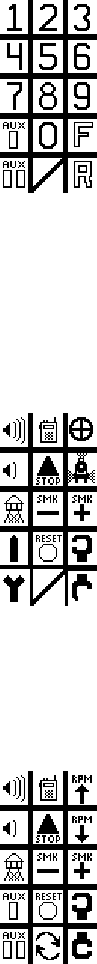
Aux 1
*Reprogramming tmcc engines pulled
Insert diagram 64 aux 1 here
Pressing Aux 1 will
1 Customize Crew- talk and Tower-Com controls as
one hit only “negative” dialogs, returning to normal.
2 Display Crew-talk and Tower-com icons negative
3 Customize any other icon controls to a “unique” one
hit only application,
4 Return to normal after any keystroke.
Aux 2
Insert diagram 65 aux 2 here
Pressing Aux 2 will
reserved
Switch
Insert diagram 66 switch control through here
Switch Through
Pressing the Switch Through button will
1 Throw an addressed switch through (or straight)
Switch Out
Insert diagram 67 switch control out here

44
Pressing the Switch Out button will
1 Throw an addressed switch out (or curved)
Halt
Insert diagram 68 HALT here
Pressing Halt will
1 Stop all trains
Set
Insert diagram 69 set here
Pressing Set will
1 set address ID#
2 set Stall
3 provide programming function for some layout
control components.
L, M, H.
Insert diagram 70 LMH here
Pressing L, M, H, will
1 Choose momentum level
2 Display a momentum graph for that level
3 Provide programming function for some TMCC
trackside components.

45
OFFICIAL R.R. SPEED COTROL (ew Lionel legacy engines only)
Dec 6 06 ny created
Five (5) Official Railroad speeds are assigned to dedicated speed icons in the
CAB 2 touchscreen. You must press the Cab 2 SPEED button to bring up the dedicated
speed icons in the touch-screen. Dedicated speeds are commanded whenever you press
one of the dedicated speed buttons. To leave the dedicated speed touchscreen just press
SPEED again.
Insert diagram “speed” button here….. insert diagram” dedicated speed touchscreen”
here
OPERATIG WITH OFFICIAL RAILROAD SPEEDS
Press a Dedicated speed Touch-screen ICON
1 You will hear a dialog between the dispatcher and the engineer
2 The addressed train will move towards the dedicated speed.
LIOEL RESEARCH
Train speed Definitions:
LIONEL research information is culled from several sources, including
Illinois Central Railroad Information, Michigan Railroads, Union
Pacific Railroad Terms Glossary and North American Signaling Basics.
Restricted speed : 5 mph
A speed that will permit stopping with one-half the
range of vision, looking out for train, obstruction, switch not properly
lined or broken rail, but not exceeding either 15 or 20 miles per hour as
defined by the operating railroad.
Slow speed: 15 mph
Slow Speed: A speed not exceeding 15 or 20 miles per hour, as defined by
the operating railroad.
Medium speed : 30 mph
Not exceeding either 30 or 40 miles per hour, as defined by
the operating railroad.
Limited speed : 45 mph
Not exceeding 45 or 60 miles per hour as designated by the
operating railroad.
Normal speed : 65 mph
The maximum authorized speed shown in the timetable.
HighBall: Maximum speed of locomotive
Not a prototypical speed.
46
Brake: Deccelerate at momentum speed to ROLL (speed step one)
TOUCH-SCREE
The Legacy touch-screen adapts to your operating condition.
If you are addressing, it is a numeric display.
diagram 57.1 of numeric display touch-screen
If you are operating underway, it is a graphic display of control functions for the
particular engine you have addressed. (Legacy engines only)
diagram 57.25 of steam engine control (underway) (with switch addressed) touch-
screen
47
diagram 57.3 of diesel engine control (underway) (with sequence) touch-screen
48
If you are operating at stop, it is a graphic display of control functions for the particular
engine you have addressed. (Legacy engines only)
diagram 57.4 of diesel engine control (stopped) (with switch addressed) touch-screen
diagram 57.45 of steam engine control (stopped) touch-screen
49
If you are operating with dedicated engine speeds, it gives you the 5 standard R.R. speeds
and “full speed” as single commands.
diagram 57.5 of dedicated speed touch-screen
diagram 57.55 of dedicated speed touch-screen (with switch addressed)
The Legacy Control touch-screen adapts to whatever you are controlling.
Future LIONEL Legacy Control products may have engine or accessory specific features
that do not come as standard on other products. When you purchase one of these future
products, there will be an additional system upgrade memory module for the unique
touchscreen.
The system upgrade memory module will provide a chronological system upgrade for
your remote and/or base. Follow the simple instructions enclosed with your latest product
to download new touchscreens into your system. If you have more than one system
upgrade for more than one product at the same time, it is only necessary to download the
latest chronological version.
50
RECORD
Use the Legacy <RECORD> button to record any action that you desire to
see repeated.
A complete recording always consists of a stored trigger command and an
action sequence. Once the action is recorded, playing back is simple.
The Trigger Command, which can be any combination of key presses, will
always playback that sequence automatically whenever it is entered.
Recording
Insert diagram 59.5 (Record button, LED) here
To create the stored trigger, press <record> briefly
1 The led blinks fast
2 In this state the user enters the trigger commands.
ie, <TR> <1>
3 The led goes out on the first key-press
To erase the stored trigger and try again, press <record> and hold it
down
1 The led blinks fast
Release the record button
1 The trigger is erased
2 The led stops blinking
To save the stored trigger, press <record> briefly
2 The led blinks slowly
To record the sequence of commands, once the trigger is saved and the
led is blinking slowly, the user enters the sequence to be recorded, ie,
<AUX 1> <7 >.
1 The led goes out on the first keypress
To erase the sequence of commands and try again, press <record> and
hold it down.
1 The led blinks slowly
Release the Record button
1 the sequence is erased
2 the led stops blinking
To save the recorded sequence, press <record> briefly
1 The led emits a steady light for 3 seconds,
confirming recording done
51
To save the complete recording,
1 Press <SET>
2 The screen reads TR1 sequence saved
In summary, if the led is blinking fast, you can record a trigger. If the led
is blinking slowly, you can record a sequence. If the led is not blinking,
you can press <record> briefly to clear and start recording
Note that only one recording can be saved for any trigger. Recording a
new sequence with the same trigger will erase the sequence previously
recorded with that trigger.
Playback
Because he trigger is a sequence of commands, the recording plays
whenever that sequence is entered.
Memory
There is a limit to the memory available for recording.
To see how much memory you have available,
1 Press <CTC>. Scroll to “Record Options”.
2 Then Press <MEM> to view Record Memory
(graph)
Now you can see how much memory remains. The grey-bar represents
Memory used.
While you are viewing, notice the boxes in the bottom of the screen
Insert diagram 59.7 of (Record Options “Memory”) here
The triggers are illustrated alpha-numerically in boxes above each soft-
key.
1 Scroll through all the triggers.
2 Soft key buttons are used to select each trigger to
view the recording.
When the trigger you are looking for appears,
1 press the soft-key under that Trigger.
Now you can view all the info about that recording.
1 -You will see the stored Trigger.
2 -You will see all the commands making up the
sequence, in order.
3 -You will see the duration in seconds.
4 -You will see the % of memory used by the selected
sequence.
52
Erase
If you wish to erase a sequence and start again with the same sequence
trigger,
1 just press record briefly
2 enter the same trigger, and
3 start again as described under RECORD
If you wish to erase a sequence, follow the directions below.
To erase any sequence, press <record> briefly
1 The led blinks fast
In this state the user enters the trigger commands for that sequence ie,
<TR> <1>
2 The led goes out on the first keypress
To erase the stored trigger and sequence, press <record> and hold it
down
1 The led emits a steady light for 3 seconds,
confirming erasing done
2 The screen reads TR1 sequence erased
Insert diagram 59.9(sequence erased) here
53
FEEDBACK
See. Hear. Feel.
As your engine’s Commanded Speed moves toward your Target Speed,
you can hear, see, and feel your engine at work.
Pick up the CAB 2. Experiment for yourself. Momentum is default “M”
medium setting. See how the Momentum affects your engine’s rate of
Acceleration.
Listen. Hear the laboring sounds, coasting sounds, braking sounds, RPM
changes and more as your engine moves towards its “Target Speed”.
Feel. If you have the CAB 2 “FEEDBACK” effect on, you will “feel” the
engine laboring through RPM ramps, forced braking, and other conditions.
Insert diagram 17 .1 FEEDBACK button here
54
SEQUECED COTROL SECTIO
In this next section we will introduce you to three parts of the Legacy Control system that
work together.
LEGACY VELOCITY THROTTLE
MOMETUM
LEGACY SEQUECED COTROL
Together, these control methods are a new way to control your trains.
Operating a train with the Legacy Velocity Throttle enables you to control
whistle/horn, bell, independent engine brake, crew-talk, blow-down effect,
let-offs, loading, speed and more. This is all done through sequences that
happen when you trigger them with certain throttle moves.
Though it is always possible to control these effects through the Direct
Control method, the velocity throttle is capable of operating the effects
without looking away to the Direct Controls.
You have the choice of either method, or both methods at the same time.
In this section, you will encounter new terms ROLL, TRANS, ARRIVAL
& DEPARTURE TRIGGER, and GATE. Refer to the diagram to
understand where these conditions are on the speed graph.
Insert diagram 19 “MASTER SEQUECE” here
Insert diagram 19.2 “A&D magnifier” here
Insert diagram 19.1 “Master Sequence illustrated speed graph” here
These diagrams show the full 200 speed steps in the range of the Velocity
Throttle and the Lionel Legacy system. The “Master Sequence”
illustration and Display Window “Speed Graph” illustrate where all of the
different Conditions, Triggers and Gates are located. Become familiar
with this to understand what follows next in this manual.
55
LEGACY VELOCITY THROTTLE
Rotating the Velocity throttle at different rates will result in control of effects as well
as fine to coarse control of train speed.
Velocity Throttle Speed
Velocity Throttle Speed Control with a Low momentum setting
1 Turning the rotary slowly takes 4 revolutions to go
from speed-step 1 to 200
2 Turning the rotary quickly takes less than 1
revolution to go from speed-step 1 to 200
Velocity Throttle Speed Control (with a Medium or High Momentum
setting) 1 The target line movement is the same as with the
“Low” setting
2 the grey-bar movement is affected and moves
slower than at the “Low” setting.
The Target line and Grey-bar
The Target line represents the desired speed of the train. The grey-bar represents
the commanded speed of the train. It is this difference that lets you control features like
the Auto-Brake independently of the speed of the train. Experiment with L M and H
momentum and see how it affects your train’s commanded speed compared to the Target
line.
Velocity Throttle Auto-Brake
Velocity Throttle Brake Control
Insert diagram 20 VT Brake (Target Line at speed step 1, grey bar at
50%) here
Move the target line to speed step 1 (Roll) while the grey bar is above
speed step 1
1 Trigger a brake sound during deceleration
2 Continue braking and sounds until speed step 1,
(ROLL condition) is attained.

56
3 Trigger a brake sound during deceleration until the
target line is moved up from speed step 1 (ROLL
Condition).
Velocity Throttle Horn/Whistle Control
Move the target line to speed step 200 (Maximum speed) while the grey
bar is below speed step 200
1 Trigger a Loud warning.
Move the target line below speed step 200
1 End a Loud warning.
Passing through an A&D trigger or gate
1 May trigger a warning or signal sound
2 (see Legacy Sequenced Control)
Velocity Throttle RPM Control
Velocity Throttle Diesel RPM Control
Insert diagram 24a VTSC RPM (shows rpm ticks) here
Rotate the Velocity Throttle through its range past RPM ^ markers
1 Change RPM levels.
When grey-bar increases through an RPM mark,
1 RPMs increase each time.
When grey -bar decreases through an RPM mark,
1 RPMs decrease each time.
Internal…..Mark and Bruce, Since an RPM ramp takes a definite
amount of time to play, a scheme for sending the absolute ramp up or
down commands in cue may be needed to make sure RPM ramping is
solid. Perhaps this would necessitate the standard time-length for an
RPM ramp to be identified. Commands could then be stored and sent out
on cue when the user is changing speeds with direct or low momentum
control. Or , on the other hand, if the absolute RPM level is known, the
ramps would just keep climbing until the right level is reached.
Internally in Railsounds, smoke may be triggered to correspond to the
rpms rising………The deciding factor is how long it takes the grey-bar
to go from one RPM tick to another. If that amount of time is shorter

57
than the duration of a standard ramp time, we will need a cue that plays
all the absolute ramps until they “catch up” with the grey-bar position.
Bruce may be able to do this inside RS but that would not help us with
the “FEEDBACK” cab2 vibration effects we want at RPM changes…
we need to solve this. Y
An alternative is to use the old tmcc method of ramping which is trigger
a ramp up or down whenever the throttle goes up or down. We could
fall back and use this method whenever the momentum rate is too fast to
accommodate an RPM trigger from the graph.
Velocity Throttle Direction Control
Insert diagram 25 VTSC direction (show bottom 5 steps magnified) here
Quickly turn the rotary counter clockwise, from a stop, at speed step 0
1 Change the direction of the locomotive
2 Produce a let-off sound
3 Produce an engineer dialog (some models)
4 Reverse locomotive lighting (back-up light)
Velocity Throttle Engine laboring
Insert diagram 28 VTSC laboring (Target 80 grey-bar 40) here
When the target line is above the grey bar,
1 Laboring sounds will intensify greatly, gradually
decreasing to normal (default) as the grey-bar reaches
the target line.
2 The laboring sound is affected by the distance between
the grey-bar is from the target line.
Insert diagram 28.5 VTSC laboring (Target 40 grey-bar 80) here
When the target line is below the grey-bar,
1 Laboring sounds will weaken in intensity, gradually
increasing to normal (default) as the grey-bar reaches
the target line.
2 The laboring sound is affected by the distance between
the grey-bar and the target line.

58
MOMETUM
Momentum plays a big part in exploring the new features of the Velocity
Throttle and Legacy Sequence control.
Momentum settings govern the amount of time it takes your engine to
reach its Target Speed. During that time, a lot of events happen
automatically. Momentum, the rate of your engine’s acceleration, is set to
“M” or medium as a default. Setting Momentum to “L” will greatly
increase acceleration and deceleration rates, affecting the timing of some
“sequence control” features, while setting Momentum to “H” will decrease
the rates of acceleration and deceleration, giving you more time to
experience “sequence control” transition events.
Momentum has 3 settings, L is low or direct, M is user settable, and H is
high. Engines default to “M”. Experiment with “L”, “M”, and “H”.
You can easily “customize” each engine’s “M” momentum settings and
store these settings by using the method described next:
ote diagram incorrect
diagram 18 momentum select and graph
Press and Hold the M button
1 Display a momentum graph labeled “M”.
2 Continuing to hold the button down will enable you
to use your rotary to move the grey area of the
graph up or down to a new setting.
3 Release the “M” button.
4 Now you have re-set the momentum for “M”. Try it
out and adjust it until you like it. The new setting
will be saved automatically for whatever engine you
are using. Customize the momentum settings for
each of your engines this way.
59
LEGACY SEQUECED COTROL
Lionel Legacy Control System Equipped engines only
Dec 18 06 ny …….call out Legacy only
Enter and leave the Sequenced Control mode by pressing the center-most key at the
bottom of the Touch-screen.
diagram xx.x “Sequence Control off / on key”
Sequenced Control
This section tells you how to use your Velocity throttle for performing
sequenced control operation of effects and sounds, as well as train
speed.
ARRIVAL & DEPARTURE SEQUECE
Arrival & Departure Sequence Introduction:
Control the actions and language of a train in daily operation. Prototypical
events, sequenced with arrivals and departures are at the heart of Legacy
sequenced Control. It’s all done with the velocity throttle.
Follow this sequence from departure to arrival.
A&D Start
Insert diagram 30 A&D Start (magnified bottom 5 steps) here
60
diagram 100 A&D display screen “Stop”
note………… Black-line is target. Grey-bar is commanded speed. Grey-
line signifies next event
Increase from 0 to throttle notch Trans +
1 Start smoke element (starts immediately) (Legacy engines
only)
Increase from 0 to throttle notch Trans + and wait (for three seconds)
2 Start dialog (SCENE Departure granted) (Legacy engines
only)
3 After approx 10 seconds at trans +, smoke element off.
(Legacy engines only)
diagram 101 A&D display screen “TRAS +”
Increase from trans + or 0 to throttle notch Trans ++
1 Start continuous bell sound (Legacy engines only)
2 Blow Warning Whistle /Horn
3 Ramp up Diesel RPMs
4 Start smoke fan (diesels) (Legacy engines only)
5 Let-off
STOP
+
+ +
61
diagram 102 A&D display screen “TRAS + +”
Increase from Trans+ or Trans ++ condition to (1) ROLL Condition
1 Start the train rolling
2 Show the A&D display Departure trigger grey-line
diagram 103 A&D display screen “ROLL”
note departure trigger grey-line signifies next event
A&D Departure
Insert diagram 31 A&D departure (bottom 25 steps) here
Increase from ROLL Condition to Departure trigger
A&D Departure trigger effects are
1 Whistle blow (could be prototypical signal..
Railsounds sequence) (Legacy engines only)then,
2 Departure Crew-Talk Dialog SCENE “have
departed (Legacy engines only)
3 Continuous bell stops (Legacy engines only)
A&D Departure trigger effects play if
1 Grey-bar has last been at “Stop” position
2 Target speed is set above the Departure trigger and
3 The grey-bar passes through the Departure trigger
ROLL
62
diagram 104 A&D display screen “Grey bar passes through departure
trigger” note A&D departure GATE grey-line signifies next event
A&D Post-Departure
Insert diagram 32 A&D post departure (grey-bar 40% target line 90%)
here
Grey-bar Increase from Departure trigger to A&D Gate
A&D Post departure effects are
1 long whistle blow
A&D Post departure effects play if
1 Train (grey-bar) passes up through A&D Gate
diagram 105 A&D display screen “Grey bar at A&D post-departure
Gate.”
ote pre-arrival grey-line signifies next event
63
diagram 106 A&D display screen “Grey bar passes post-departure
Gate.”
A&D Pre-Arrival
Insert diagram 33 A&D pre-arrival (target line 40% grey-bar 50%) here
Decrease through A&D Gate
A&D Pre-Arrival effects are
1 Dialog SCENE “All Clear” (in transit) (Legacy
engines only)
A&D Pre-Arrival effects play if
2 Train (grey-bar) passes down through A&D Gate after
last triggering the A&D post-departure sequence.
diagram 107 A&D display screen “Grey bar approaches pre-arrival
Gate.”
diagram 108 A&D display screen “Grey bar at pre-arrival Gate.”
64
diagram 109 A&D display screen “Grey bar passes pre-arrival Gate.”
ote A&D Arrival trigger grey-bar signifies next event
A&D Arrival
Insert diagram 34 A&D Arrival (target bar 5 grey-bar 10) here
Decrease from A&D Gate to A&D Arrival trigger
A&D Arrival effects are
1 Whistle blows (absolute whistle start and end)
2 Continuous bell begins (Legacy engines only)
3 Crew-Talk Dialog SCENE “Arriving Soon”
(Legacy engines only)
A&D Arrival effects play if
3 Grey-bar passes through the Arrival trigger after
last passing down through the A&D Gate and triggering
the A&D pre-arrival sequence.
diagram 110 A&D display screen “Grey bar approaches arrival Gate.”
diagram 111 A&D display screen “Grey bar at arrival Gate.”
Insert A&D diagram ROLL here
Auto-Brake to ROLL (with target line at speed step one)
A&D ROLL effects are
1 brake sounds end
2 Continuous bell begins (Legacy engines only)
65
A&D ROLL effects play if
1 train is at speed step one after passing through
arrival trigger
diagram 112 A&D display screen “Grey bar at ROLL”
A&D Trans –
Decreasing from Roll to throttle notch Trans -
A&D Arrival Trans - effects
1 “Brake sound” with train still in motion at Trans -
diagram 113 A&D display screen “Target line and Grey bar at trans -”
A&D Stop
Insert diagram 35 A&D stop (bottom 15 steps magnified) here
ROLL
-
66
Decrease from trans - to Stop (speed step 0)
A&D Arrival STOP effects
1 Crew talk dialog SCENE “have arrived” (Legacy
engines only)
2 A Smoke burst (absolute max element after 3
seconds and apply max fan after 6 seconds, with 2
second duration) (Legacy engines only) and
3 A simultaneous Blow-down sound in synch with
fan (absolute Rail-Sounds command) (Legacy
engines only)
A&D Arrival STOP effects play when
1 The grey-bar is at 0 from trans – condition
2 Grey-bar has passed through arrival trigger since
last stop.
diagram 114 A&D display screen “STOP”
note departure trigger grey-bar signifies next event
STOP

67
FIE TUIG VELOCITY THROTTLE SEQUECES
Dec6 06 ny changes to text
Dec 12 06 ny text changes
Insert diagram 72 velocity throttle sequenced control here
Your TMCC 2 Velocity Throttle has a series of sequences that it can
reproduce any time you move it a certain way. You “load” a sequence by
making a certain move with the throttle. One example of this is when you
have a train moving along the track with momentum engaged and you
move the speed-graph target line to speed step one. The brakes come on.
You have loaded the auto-brake with Velocity Throttle Control. You did
that just by moving the target line to speed step one. You didn’t have to
watch the speed graph to know this because you heard the brake sounds.
They only are engaged when the target line is at speed step one on the
Velocity Throttle. When you hear the brake sound stop, your train is at
speed step one or ‘ROLL” condition. Now the engine will roll along at its
slowest speed with its bell ringing. That’s what it does in speed step one,
“ROLL” condition.
You are not limited to hearing brake sounds while your train is braking
towards speed step one. Just moving the Target line to speed step 2 will
stop the brake sound, although your train may still be slowing down to
speed step 2. You control the brake sound as your engine slows down. Just
keep the target line below the grey-bar (train speed) for deceleration and
you can add brake sound effects any time just by moving the target line
back to speed step one.
When the train arrives at speed step one, “Roll” Condition, brakes stop,
and bell starts.
As we have seen earlier, between Roll and Stop, there is a condition called
Trans- on the speed-graph. You get to Trans- just by turning the throttle
down one notch from “Roll”. It doesn’t affect the speed. You are still
rolling, but now the brake sounds are back on. One more turn of the
throttle counter-clockwise takes your train from Trans- to Stop. Now the
brake sounds stop and your train is right where you want to be. The bell
stops too, lettting you know motion has stopped.
Now you take one more trip with your train. It is rolling along at more
than half speed through your layout.
Your train is traveling at a speed that is above the A&D GATE, (default
speed step 100 or half-speed). That automatically loads the Arrival-
Departure sequence. Stop your train at a station. Now that your engine has
stopped and finished a high-speed trip, after a few seconds at stop, it will
perform an automatic “Blow-Down sequence”. A blow down sequence is

68
a large plume of smoke coming from the stack and a loud blow down
sound. It lasts a few seconds. That sequence wouldn’t have happened if
your engine had not been above the Gate (default speed step 100), on its
last trip.
All of these sequences of events have events that start the sequence off,
and effects that are triggered in the sequence. You can change behavior of
each locomotive by tuning in the sounds and effects that you would like to
respond and the speed step (event) that you would like to trigger the
sequence. You can also set exactly when the effects will happen by
adjusting the Trigger. Just set a new speed step for that Trigger in the
Sequence Options section of INFO. If you then like the old setting better,
just press default and you’re right back to factory settings. You can’t hurt
anything by making a mistake.
Once your engine is addressed, these “SEQUENCE TUNING”
adjustments are all made in the INFO menu, and they stay with your
engine until you change them again. You have the choice to adjust them if
you like. You can just turn them off and run your train directly with the
standard controls by touching the Sequence Control soft-key on the touch-
screen. You can even use both methods at the same time.
When you run your engines in a lash-up, the head-end engine sequences
will be the default setting for all the lashed-up engines. Sequenced sound
effects like Whistle/Horn, brakes, bell and crew-talk only come from the
head end unit.
ACCESSIG SEQUECE OPTIOS
Dec 6 06 ny created
Insert diagram72 sequence options menu choices here
In Sequence Options, you can disable parts of sequences and operate the
Velocity Throttle without them. You can elect to disable the whole
sequence. In arrival and departure sequences, the trigger and gate can be
reset. Trans + and - settings can not be reset. Roll Condition can not be
reset.
To adjust sequence options:
Press Engine
1 Enter ID#
Press INFO
69
3 scroll to sequence options
4 choose from A&D, Dialog, Warning sounds
70
TABLE OF OPTIOS
Throughout this manual references to Options are made. In the IFO menu,
Options can be selected. The following Table of Options shows the possibilities that
are available to you in tuning the performance of your Lionel products. From time
to time, more Options may be added to particular product types. Use the “otes”
pages in the back of this manual to keep up to date on the latest advances.
This manual will be updated regularly to include options added for new
products. A good example of options coming in the future would be “Railsounds
tuning”. Another appropriate example would be “Prophecy” products, which will
introduce more and more features to the Lionel Legacy Control system. Manuals
that come with future controllers will be updated to reflect these advances, both in
the text, and the Options tables.

71
EGIE OPTIOS
Dec 2 06 ny added REL…moved speed control to near control types
Control Types:(choose one)
TM1 TMCC 1 Original Lionel 32 absolute steps
Speed Graph
Naming
TPC TPC Track Power Control 200 relative steps,
Speed Graph
LEG Legacy Legacy engines 200 absolute steps
Speed Graph
Naming
REL Relative OEM and Accessories name and info no graph
Speed Control
SPD Servo motor Legacy and Odyssey Toggle servo on and off
Engine Types (choose one)
DSL Diesel Diesel engine Control Legacy RPM monitoring
STM Steam Steam engine Control Legacy Chuff monitoring
ELC Electric Electric engine Control ??
TBN Turbine Turbine engine Control ??
SUB Subway Subway control special L&R door commands
SPC Special Station-sounds/crew-talk Special addressing for dialog
Rolling stock in consist
ame
Dec 3 06 ny …..changed ABC to AM
NAM Name Assign name Brings up naming screen
Sound types: (choose one)
RS Railsounds RS1 RS2.5 engines Basic functions
RS4 Railsounds4 RS4 engines Additional Crew Talk
Aux 1 qualifier pos/neg
RS5 Railsounds5 RS5 engines Additional laboring(on timer)
3 & 6 blow-down /let-off
Additional Crew Talk
Aux 1 qualifier pos/neg
LRS Railsounds5+ Legacy engines Real time whistle/horn

72
Enhanced laboring (on timer)
3&6 same efx as RS-5
Additional Crew Talk
Aux 1 qualifier pos/neg
PRS Railsounds Prophecy engines TBA
Sequence Options
GAT VTSC All types Adjust A&D Gate
TRI VTSC All types Adjust A&D Trigger
TLK VTSC All types Crew Talk on /off toggle
DEF VTSC All types Return to default settings
H&W VTSC All types Horn/Whistle blows at
Triggers and Gates
Direct Controls
BRK Auto-brake All types Enable brake sounds
When target is 0
DIR Legacy Dir All types Three-step direction control
1
st
Auto-brake
2
nd
Fast-brake to stop (if
Rolling at any speed)
3
rd
Direction change (if
stopped)
Speed Displays: (choose one)
SP1 Speed Graph All types xxxxxx Large Graph,
Train-Brake/Name at top
SP2 Numeric All types xxxxxx Large MPH
Train-Brake/Name at top
SP3 Combination All types xxxxxx Large Graph and MPH box
Train-Brake/Name at top

73
TRAI OPTIOS
Dec 3 06 ny created doc
View
VU View View Lashup Brings up lash-up view
Screen
Build Lashup
BLD Lash-up Build Lashup Brings up Lashup screen
Train Types (choose one)
PAS Passenger Passenger train traffic priority
FRT Freight Freight train traffic priority
Clear
CLR Clear Clear Train address Brings up cleared lash-up
Screen
ame (assign name)
NAM Name Assign name Brings up naming screen

74
ACCESSORY OPTIOS
*dec 3 06 ny…..created
Control Types:(choose one)
LEG Legacy Legacy ACC controller 200 absolute steps
REL Relative TMCC ACC controller Relative speeds
Speed Control
SPD Servo motor speed control
Relative control Toggle servo on and off
ACC Types (choose one)
ENG Engine ACC with motor
LIT Light Lighting accessory
ame
NAM Name Assign name Brings up naming screen
75
ROUTE OPTIOS view, edit, clear, name, SPD
View
VU View View Route Brings up Route View screen
Edit
EDT EDIT Edit Route Brings up Route Build screen
ame
NAM Name Assign name Brings up naming screen
Clear
CLR Clear Clear Route Brings up empty Route Build
screen
Throw rate
SPD Throw rate Set throw rate Choose rate that switches
throw in a route

76
SWITCH OPTIOS
Dec 4 06 ny created
ame
NAM Name Assign name Brings up naming screen
77
"NOTE:
This equipment has been tested and found to
comply with the limits for a Class B digital
device, pursuant to Part 15 of the FCC Rules.
These limits are designed to provide
reasonable protection against harmful
interference in a residential installation.
This equipment generates, uses, and can
radiate radio frequency energy and, if not
installed and used in accordance with the
instructions, may cause harmful interference
to radio communications. However, there is no
guarantee that interference will not occur in
a particular installation. If this equipment
does cause harmful interference to radio or
television reception, which can be determined
by turning the equipment off and on, the user
is encouraged to try to correct the
interference by one or more of the following
measures:
-- Reorient or relocate the receiving antenna.
-- Increase the separation between the
equipment and receiver.
-- Connect the equipment into an outlet on a
circuit different from that to which the
receiver is connected.
-- Consult the dealer or an experienced
radio/TV technician for help.
WARNING: Changes or modifications not
expressively approved by the party responsible
for compliance could void the user's authority
to operate the equipment. The term "IC"
before the radio certification number only
signifies that Industry Canada technical
specifications were met."
78
79
WORK AREA…HARD HAT REQUIRED
DIRECT COTROL OPTIOS
Direction
Choose Direction Control methods
VEL (Default) Velocity Throttle Direction Control
OFF Normal (one press) Direction Control only
DEF Return to Factory Default
Stall
SET Set stall by turning rotary and using graph while pressing
SET softkey
ReleaseSET soft-key to save
SPEED GRAPH OPTIOS
Speed graph
Choose “Look” of Speed Graph
SP1 (Default) Large graph, no name
SP2 Large numeric output instead of graph
SP3 Large graph with additional numeric readout
SP4 Big name with train-brake graph
DEF Return to Factory Default
ROUTE OPTIOS
SWITCH OPTIOS
ACCESSORY OPTIOS
SYSTEM OPTIOS
EGIE OPTIOS
Stall
Insert diagram 43.5 stall set sequence ( set button and graph) here
Introduction
“Stall” is used to establish the amount of power required as a
locomotive first starts moving. Once “stall” is set, it ignores any speed steps
below that threshold. Engines without speed control (Odyssey or Legacy
Speed Control) may benefit from a new “stall” setting.
80
Press SET (headlight will blink)
Operate your engine on a straight piece of level track, decelerating until it
just stalls (stops moving).
Press SET again (headlight will stop blinking)
STALL condition is set. Now decelerating will take your engine to this
new STALL condition. Your engine will always start motion right from
the STALL condition.
CAB MODES
Your CAB 2 is already in its default CAB 2 MODE.
Insert CAB 2 diagram with CTC button and Cab Mode screen here
You can go to the CAB MODE section of the Central Train Control menu
by pressing the CTC button and scrolling to the CAB Mode screen.
There you can select between Cab 1 and Cab 2 operation.
Cab 1 is just like the traditional TMCC Cab 1 operation, with the
addition of the display screen.
Cab 2 operation contains all the Legacy features.