Lionel CABIL Remote Control User Manual
Lionel L.L.C. Remote Control
UserManual.wiki
>
Lionel
>
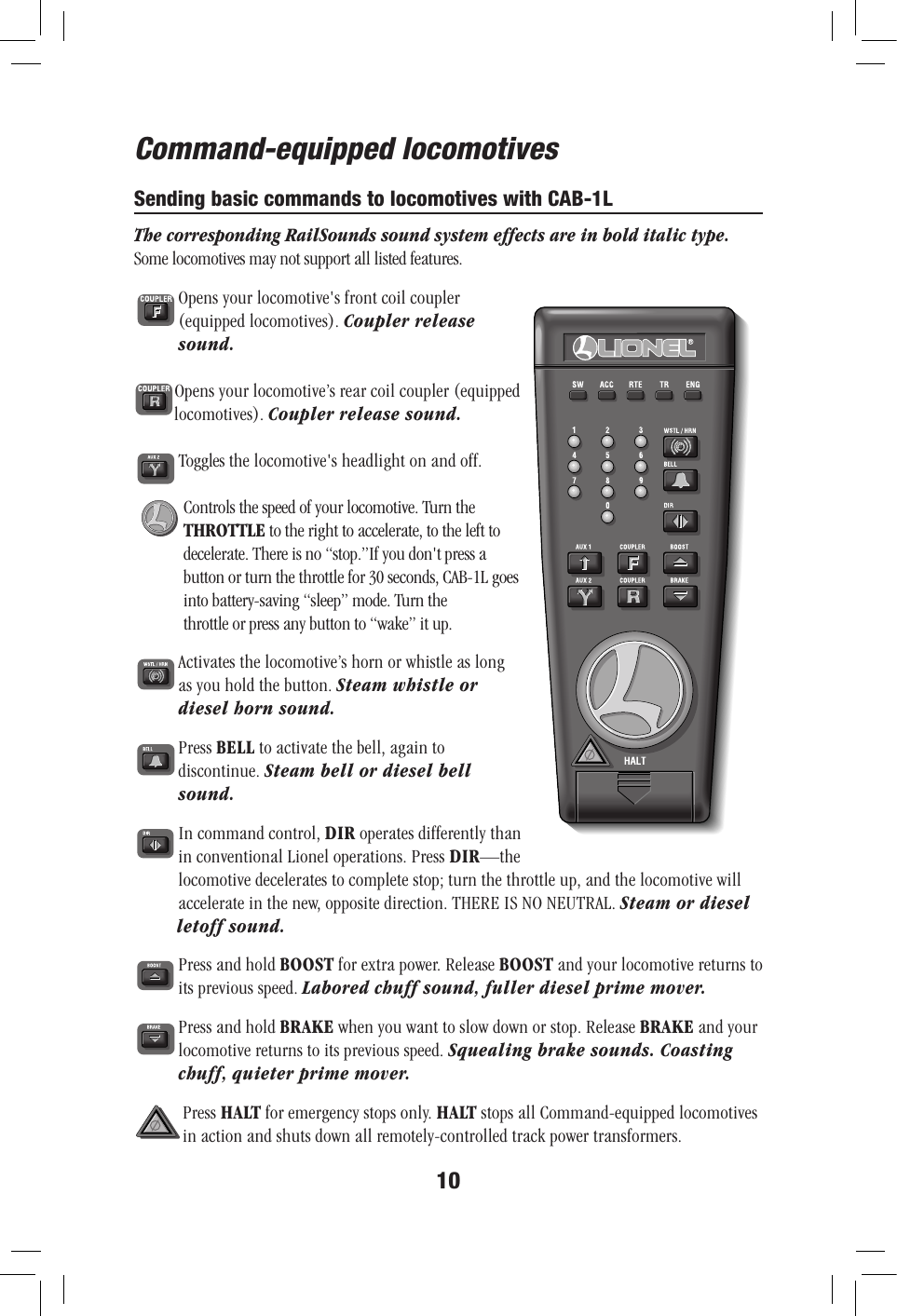
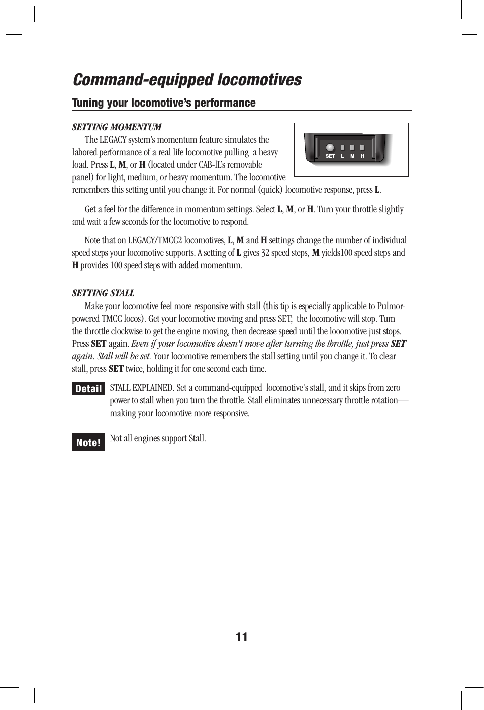
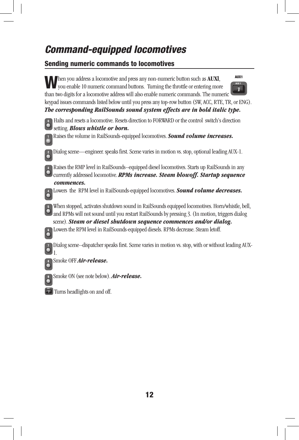
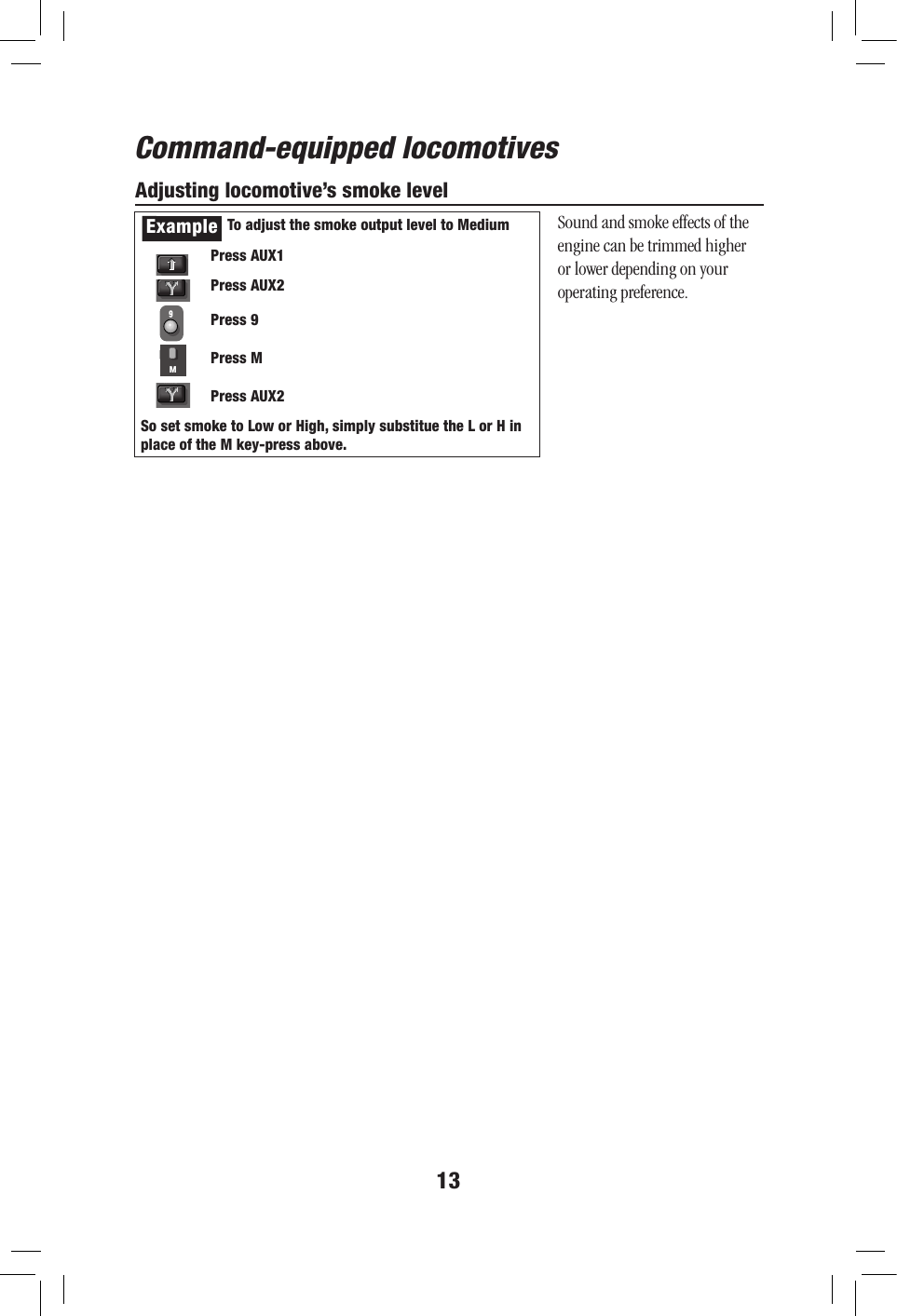
CABIL User Manual
User Manual
Navigation menu
Upload a User Manual
Namespaces
Wiki Guide
HTML
PDF
Info
Views
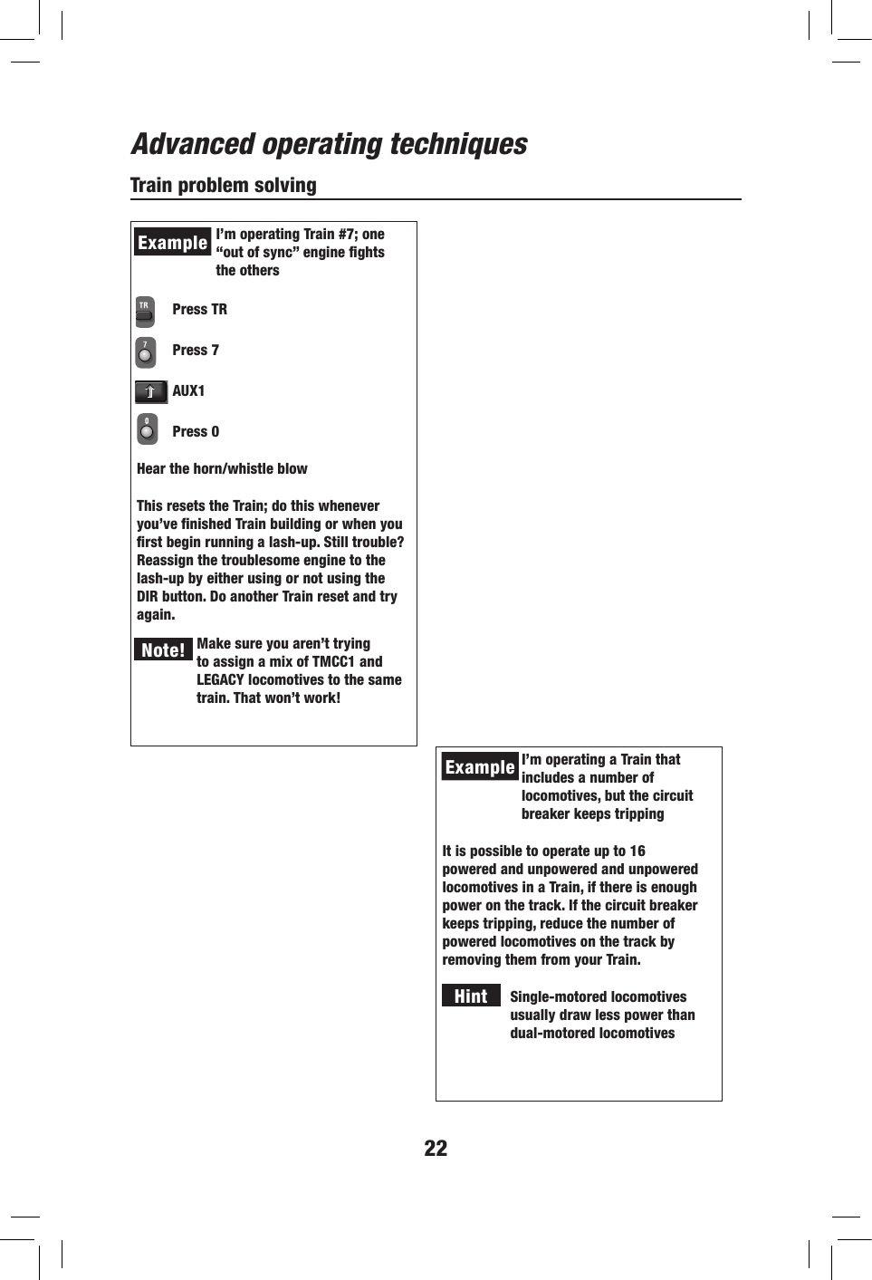
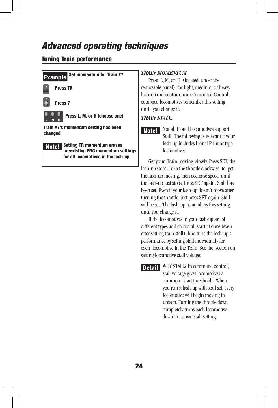
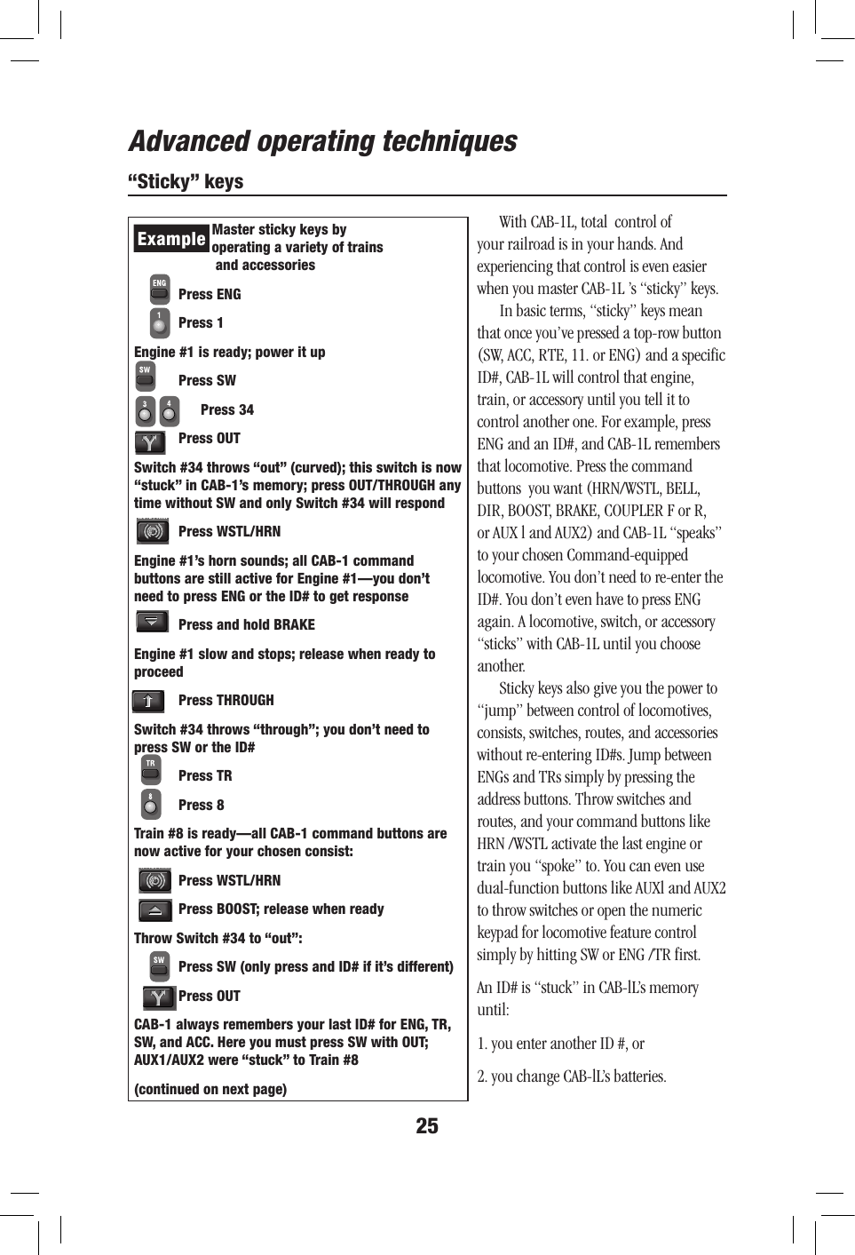
User Manual
Discussion / Help
Navigation