Lippert Components IDS23004 WiFi On-The-Go User Manual
Lippert Components WiFi On-The-Go Users Manual
Users Manual
Quick Start Guide
4G LTE
Wireless Hotspot
CCD-0001336
NOT APPROVED FOR PUBLIC RELEASE
06/08/18
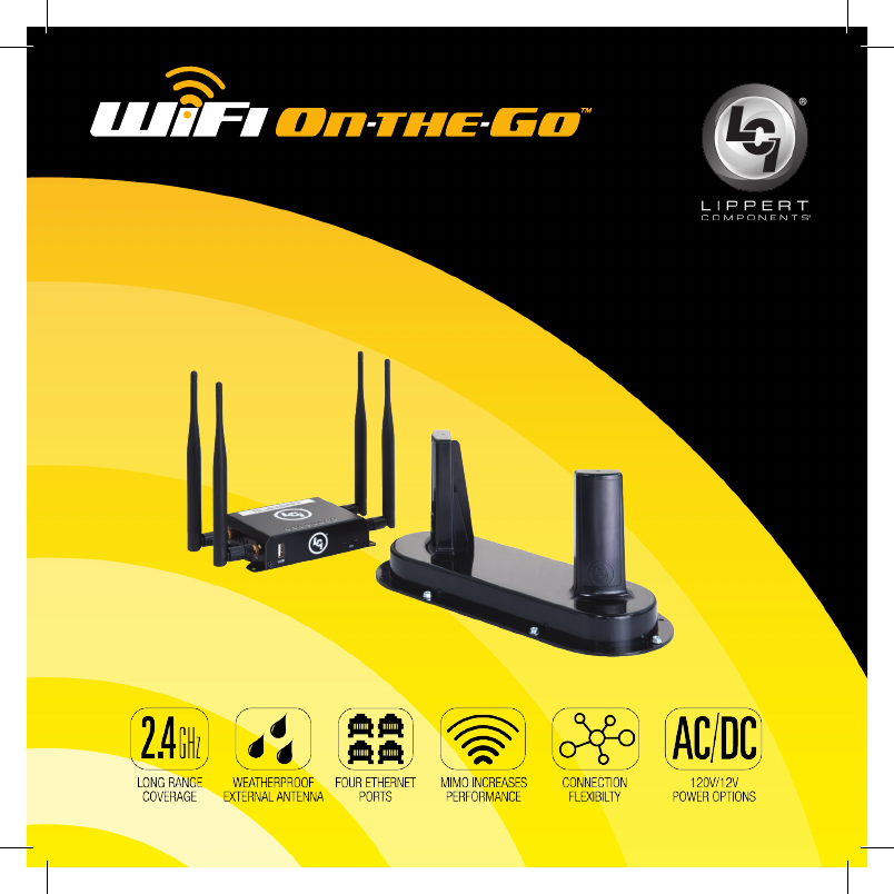
The WiFi On-the-Go™ was designed and engineered
for the mobile lifestyle. The weatherproof, external
cellular antenna array increases your signal range
far beyond a simple “o-the-shelf” mobile hotspot.
WiFi On-the-Go™ utilizes Direct Link Technology specically
designed to go wherever you go. Direct Link Technology
provides the fastest 4G LTE connectivity available, up to
150Mbps per second, so you’re connected wherever the
road may take you.
Key Features:
• Direct Link Technology provides the fastest 4G LTE connectivity available,
up to 150Mbps
• Weatherproof externally mounted 4G antenna provides superior coverage
• Designed and engineered for the mobile lifestyle
• 2.4 GHz WiFi antennas designed to provide coverage at a longer range.
• More secure connection than open WiFi networks
• Dual power options; 120V AC/DC adapter or 12V DC/DC adapter
• Four additional Ethernet ports connecting additional devices
• MiMo technology for use with multiple devices
• Compatible with 4G LTE Bands 2, 4 and 12 (AT&T and T-Mobile)
NOT APPROVED FOR PUBLIC RELEASE
06/08/18
4 5
Additional Information Sources
WiFi On-the-Go™ is compatible with AT&T® and T-Mobile® cellular
service using LTE bands 2,4 & 12. In order to activate your
WiFi On-the-Go™ hotspot, the owner will need to purchase their
own AT&T® or T-Mobile® nano Sim card and plan. The AT&T® and
T-Mobile® trade names and logos are registered trademarks of AT&T®
and T-Mobile® US, Inc. respectively.
Additional information about this product can be obtained from
lci1.com/support or by using the myLCI app. Replacement components
can be ordered from https://store.lci1.com/ or by using the myLCI app.
The myLCI app is available for free on iTunes® for iPhone® and iPad®
and also on Google Play™ for Android™ users. iTunes®, iPhone® and iPad®
are registered trademarks of Apple Inc. Google Play™ and Android™ are
trademarks of Google Inc.
Safety Information
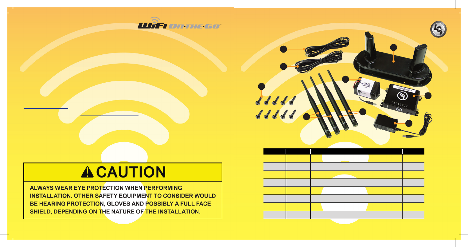
Parts List
Letter Part# Description Qty
A 715645 Coax Cable, 10’ 2
B 722255 External Cellular Antenna 1
C 383635 #8 x 3/4” Stainless Steel Pan Head Screw 10
D 722251 2.4 GHz WiFi Antenna 2
E 722252 4.0G Cellular Antenna 2
F 716722 12V DC/DC In-line Power Supply 1
G 722250 Cellular Gateway 1
H 722253 120V AC/DC Adapter 1
B
DE
F
G
Fig.1
A
A
H
C
NOT APPROVED FOR PUBLIC RELEASE
06/08/18
6 7
Preparation
The WiFi On-the-Go is a portable device but can be fastened to a mounting
surface if desired. If the external cellular antenna is not a permanent mount
there are a number of methods of temporary mounting that can be utilized
at the retail customer’s discretion, i.e. hook and loop material, two sided tape,
etc. Use the method best suited for the temporary mounting surface.
If the external cellular antenna is not permanently attached with all weather
sealant, the antenna should not be exposed to water.
The 12V DC/DC power adapter (Fig.1F) can be used to ensure a smooth
power supply to the cellular router when connected to various 12V batteries
or systems such as vehicle, solar power bank, etc. The user will need
to determine which connection type they will need to add to the red/black
wires, such as a cigarette lighter adapter or banana clips, to suit their
specic application.
For immediate use of WiFi On-the-Go™:
1. Attach the two, 4.0G cellular antennae (Fig.1E) to the corresponding
ports of the cellular gateway (Fig.1G).
2. Attach the two 2.4GHz WiFi antennae (Fig.1D) to the corresponding
ports of the cellular gateway.
3. Plug the 120V AC/DC (Fig.1F) or 12V DC/DC (Fig.1H) adapter’s
power supply barrel connector into the back of the cellular gateway.
4. Plug the 120V AC/DC adapter into a wall outlet or connect the red
and black wires of the 12V DC/DC adapter to a 12V power source.
5. See Activation and Operation sections to complete the process.
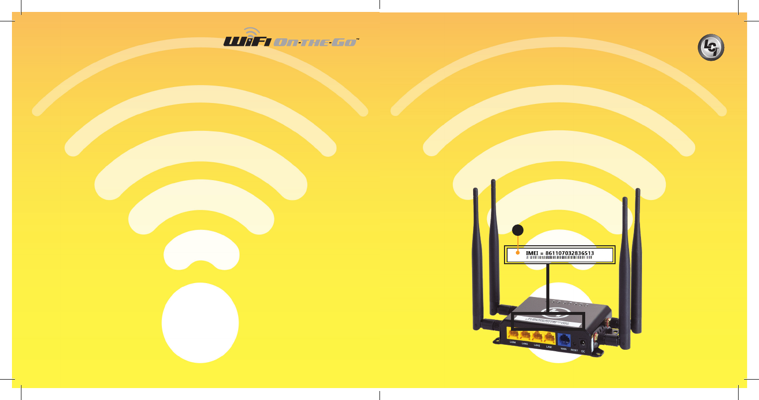
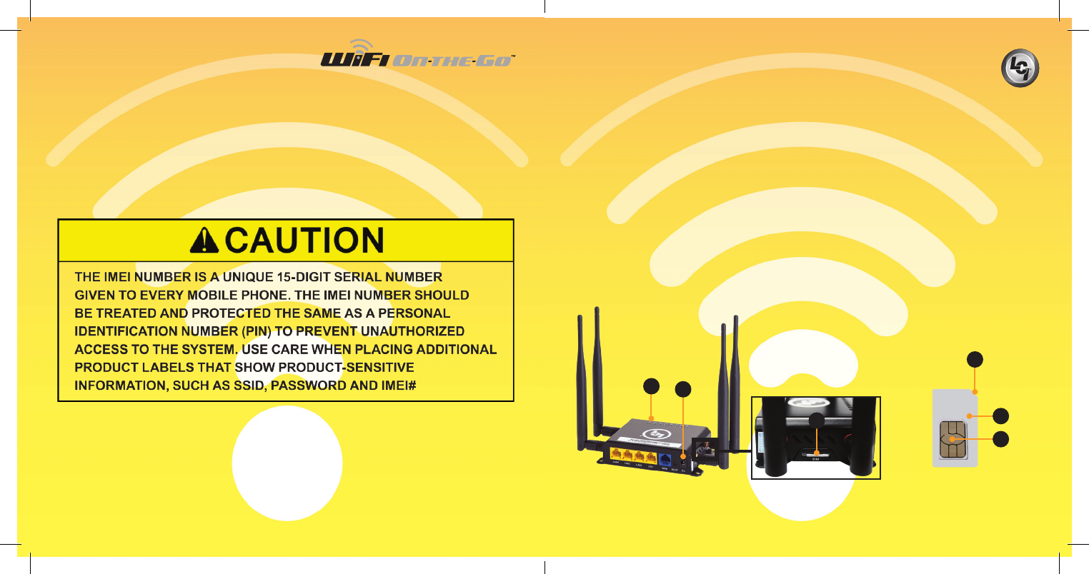
Activation
Before visiting AT&T® or T-Mobile®, make sure to have the IMEI
(International Mobile Equipment Identity) number available.
The IMEI number is printed on the WiFi On-the-Go™ label (Fig.2A).
The IMEI number is a unique 15-digit serial number given to every
device which can then be used to check information such as the device’s
Country of Origin, the Manufacturer and its Model Number.
Whether currently an AT&T® or T-Mobile® Wireless customer or not,
contact AT&T® or T-Mobile® customer service or visit the nearest AT&T®
or T-Mobile® Wireless corporate store to purchase a nano SIM card.
Fig.2
A
NOTE: For more comprehensive instructions and various options, visit
Lippert Components website at https://www.lci1.com/assets/content/support/manuals/
Electronics/WiFi_On_the_Go____Aftermarket_Manual.pdf
NOT APPROVED FOR PUBLIC RELEASE
06/08/18
8 9
System Requirements
WiFi On-the-Go™ parts needed to activate the system:
• Assembled WiFi On-the-Go™ cellular gateway with antennae
• AT&T® or T-Mobile® nano SIM card
• Android, iOS smart device or personal computer
Activation Using AT&T or T-Mobile SIM Card
1. Disconnect the 120V AC/DC adapter or the 12V DC/DC power source
from the cellular gateway (Fig.3A).
2. Locate the SIM card slot on the side of the cellular gateway (Fig.3B).
3. Gently push in on the edge of the nano SIM card adapter (Fig.3B)
and release, the SIM card adapter will pop out.
4. Position the SIM card adapter’s beveled edge on the top right hand
corner (Fig.4C), insert the nano SIM card (Fig.4B) purchased from AT&T
or T-Mobile at the same position, into the nano SIM card adapter (Fig.4A).
NOTE: Take caution when inserting the SIM card adapter into the SIM
card slot opening to ensure that the adapter is NOT inserted below the
SIM card slot opening.
Fig.3
A
C
Fig.4
C
A
B
B
.
NOT APPROVED FOR PUBLIC RELEASE
06/08/18
10 11
5. Insert the nano SIM card adapter with the nano SIM card into
the SIM card slot (Fig.3B) until a “click” sound is heard.
NOTE: The “click” sound means the SIM card is now securely latched
into the SIM slot.
6. After making sure the SIM card is rmly seated, connect the 120V
AC/DC adapter or the 12V DC/DC adapter to the cellular gateway (Fig.3A).
7. Verify power and connectivity with the Wi On-The-Go™ LEDs
(Fig.3C). Lights will ash when connected.
Operation
After successful activation of Wi On-The-Go™, use a mobile device
to connect to the 4G LTE wireless hotspot.
Connecting to Wi On-The-Go™
1. From the device’s wi- settings, select Wi On_the_Go_9d84.
The password will be blank.
2. To rename the hotspot (ESSID) and set the security settings with
a login password:
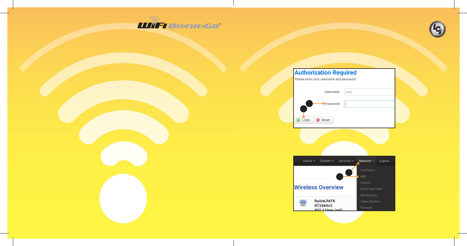
A. Open a web browser.
B. Type 192.168.1.1 into the address bar.
C. When prompted, enter the following default username and password
(Fig.5A) and click Login (Fig.5B).
I. Username: root
II. Password: admin
Fig.5
Fig.6
3. After entering the default username and password, from the top menu
bar select the “Network” dropdown menu (Fig.6A).
4. Next, click on “Wi” (Fig.6B).
A
B
A
B
NOT APPROVED FOR PUBLIC RELEASE
06/08/18
12 13
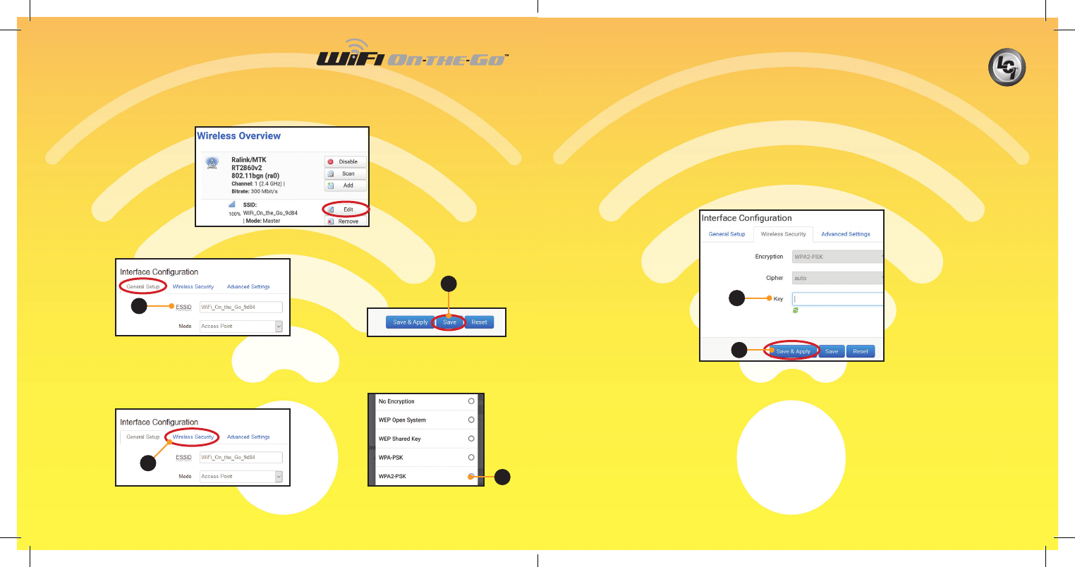
B. If preferred, rename the hotspot (ESSID) here (Fig.8A) and click Save
(Fig.9A).
Fig.7
Fig.8
A. Click on the Edit button under the “Wireless Overview” section
(Fig.7), then scroll to the bottom of the page.
II. Enter a new password in the “Key” eld (Fig.12A). The password
MUST be at least eight characters.
NOTE: For easy retrieval of a forgotten password, it is recommended to write
down and store the new password in a secure location or use a password
management encrypted database that may be located on your personal
computer or mobile device.
III. Click on “Save & Apply” button (Fig.12B).
NOTE: “Waiting for changes to be applied” may be visible until sign in is
completed.
5. Sign into the hotspot, again.
NOTE: This will be the default hotspot name or the new name given in
step 4B.
6. Select the hotspot from your mobile device’s Wi-Fi settings.
A. If the security password was not changed, no password will be
required to join the hotspot.
B. If the security password was changed (step 4CII), enter the new
password.
A
C. Click on the “Wireless Security” tab (Fig.10A) to ensure Wi-Fi security.
I. From the menu, select the desired level of security. LCI recommends
WPA2-PSK (Fig.11A).
Fig.9
Fig.10 A
Fig.12
A
B
A
Fig.11
A
NOT APPROVED FOR PUBLIC RELEASE
06/08/18
14 15
Notes
FCC 15B statement:
This equipment has been tested and found to comply with the limits for a Class B digital device, pursuant to part 15
of the FCC Rules. These limits are designed to provide reasonable protection against harmful interference in a residential
installation. This equipment generates, uses and can radiate radio frequency energy and, if not installed and used in
accordance with the instructions, may cause harmful interference to radio communications. However, there is no
guarantee that interference will not occur in a particular installation. If this equipment does cause harmful interference to
radio or television reception, which can be determined by turning the equipment o and on, the user is encouraged to try
to correct the interference by one or more of the following measures:
• Reorient or relocate the receiving antenna.
• Increase the separation between the equipment and receiver.
• Connect the equipment into an outlet on a circuit dierent from that to which the
receiver is connected.
• Consult the dealer or an experienced radio/TV technician for help.
FCC Part 15 compliance statement:
This device complies with part 15 of the FCC Rules. Operation is subject to the following two conditions:
(1) This device may not cause harmful interference, and (2) this device must accept any interference received, including
interference that may cause undesired operation.
IC User manual notice:
This device contains licence-exempt transmitter(s)/receiver(s) that comply with Innovation, Science and Economic
Development Canada’s licence-exempt RSS(s). Operation is subject to the following two conditions:
1. This device may not cause interference.
2. This device must accept any interference, including interference that may cause undesired
operation of the device.
Non-modication Warning
Any changes or modications to this device not expressly approved by the party responsible for compliance could void
the user’s authority to operate this equipment.
RF Exposure Statement
This equipment complies with FCC/IC radiation exposure limits set forth for an uncontrolled environment and meets
the FCC radio frequency (RF) Exposure Guidelines and RSS-102 of the IC radio frequency (RF) Exposure rules. This
equipment should be installed and operated keeping the radiator at least 20cm or more away from person’s body.
NOTE: Do not press “RESET” on the back of the cellular gateway unless
directed by Lippert Customer Service. Reset will take the device back to
factory settings and make the device inoperable.
NOT APPROVED FOR PUBLIC RELEASE
06/08/18
Should you have any questions, please do not
hesitate to contact us at (574) 537-8900 or by
email at customerservice@lci1.com. Self-help
tips, technical documents, product videos and a
training class schedule are available at lci1.com
or by downloading the MyLCI app.
Contact
Lippert Components Incorporated
part no. 722050
CCD-0001336
NOT APPROVED FOR PUBLIC RELEASE
06/08/18