Listen Technologies 700-002 LPRS Model LT-700-072 User Manual
Listen Technologies Corporation LPRS Model LT-700-072
Exhibit 8
User’s Manual
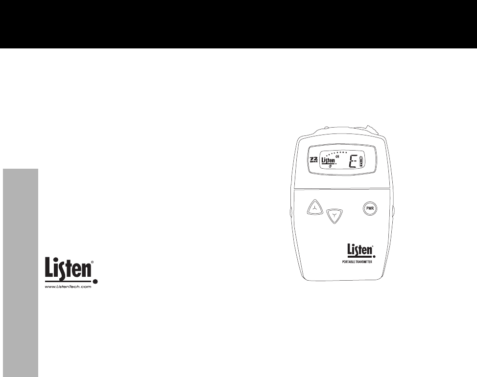
LT-700 Portable Transmitter
Don’t miss a single sound. Listen.
Listen Technologies Corporation
8535 South 700 West, Suite A
Sandy, Utah 84070-2515 USA
Telephone: +1.801.233.8992
Toll Free (North America): 1.800.330.0891
Fax: +1.801.233.8995
E-mail: info@ListenTech.com
Listen®and the Listen logo are registered trademarks of Listen Technologies Corporation

Welcome to Listen!
i
Dear Valued Customer,
Thank you for choosing Listen! All of us at Listen are dedicated to providing you
the highest quality products and prompt, efficient customer care. Our products are
manufactured in an ISO-9000 factory that has been independently certified to the
highest quality standards. We stand ready to answer any questions you might have
during installation or in the operation of our products. Should there be any
problems with your Listen products, we are ready to help you in any way we can.
Should you have any comments on how we might improve our products or our
service, we’re here to listen. Here’s how to reach us:
Telephone: +1.801.233.8992
Fax: 1.801.233.8995
Toll Free (North America): 1.800.330.0891
E-Mail: support@ListenTech.com
Web: www.ListenTech.com
Thank you... and enjoy your listening experience!
Best regards,
The Listen Team
Listen™ and the Listen Logo are registered trademarks of Listen Technologies Corporation.
LT-700_2004_02_18 © 2004 Listen Technologies Corporation. All Rights Reserved.

Welcome to Listen!
ii
· LT-700-072 (72MHz or 216MHz)
· Warranty Card
· User Manual
LT-700 Package Contents
72 MHz: LT-700-072
216 MHz: LT-700-216
Listen Part Number
See pages 32-33.
Optional Accessories

iii
this page intentionally left blank

Table of Contents
1
Architectural Specifications . . . . . . . . . . . . . . . . . . . . . . . . . . . . . . . . . . . . . . . . . . . . . . . . . .2
Specifications . . . . . . . . . . . . . . . . . . . . . . . . . . . . . . . . . . . . . . . . . . . . . . . . . . . . . . . . . . . . . .2
Quick Reference . . . . . . . . . . . . . . . . . . . . . . . . . . . . . . . . . . . . . . . . . . . . . . . . . . . . . . . . . . . .4
Setup Instructions . . . . . . . . . . . . . . . . . . . . . . . . . . . . . . . . . . . . . . . . . . . . . . . . . . . . . . . . . .7
Operating Instructions . . . . . . . . . . . . . . . . . . . . . . . . . . . . . . . . . . . . . . . . . . . . . . . . . . . . .11
Programming Instructions . . . . . . . . . . . . . . . . . . . . . . . . . . . . . . . . . . . . . . . . . . . . . . . . . . .13
Charging Batteries . . . . . . . . . . . . . . . . . . . . . . . . . . . . . . . . . . . . . . . . . . . . . . . . . . . . . . . . .14
Operation with a Wall Transformer . . . . . . . . . . . . . . . . . . . . . . . . . . . . . . . . . . . . . . . . . . . .16
Supplementary Information . . . . . . . . . . . . . . . . . . . . . . . . . . . . . . . . . . . . . . . . . . . .17
Channel Selection . . . . . . . . . . . . . . . . . . . . . . . . . . . . . . . . . . . . . . . . . . . . . . . . . . . . . . .18
Listen SQ™ . . . . . . . . . . . . . . . . . . . . . . . . . . . . . . . . . . . . . . . . . . . . . . . . . . . . . . . . . . . .20
RF Reception Maximization Strategies . . . . . . . . . . . . . . . . . . . . . . . . . . . . . . . . . . . . . . .21
72 MHz Frequency Compatibility Table . . . . . . . . . . . . . . . . . . . . . . . . . . . . . . . . . . . . . .22
216 MHz Frequency Compatibility Table . . . . . . . . . . . . . . . . . . . . . . . . . . . . . . . . . . . . .24
Troubleshooting . . . . . . . . . . . . . . . . . . . . . . . . . . . . . . . . . . . . . . . . . . . . . . . . . . . . . . . . .26
Compliance Notice . . . . . . . . . . . . . . . . . . . . . . . . . . . . . . . . . . . . . . . . . . . . . . . . . . . . . .29
FCC Statement . . . . . . . . . . . . . . . . . . . . . . . . . . . . . . . . . . . . . . . . . . . . . . . . . . . . . . . . .30
Warranty . . . . . . . . . . . . . . . . . . . . . . . . . . . . . . . . . . . . . . . . . . . . . . . . . . . . . . . . . . . . . . .31
Optional Accessories . . . . . . . . . . . . . . . . . . . . . . . . . . . . . . . . . . . . . . . . . . . . . . . . . . . . .32
Table of Contents

Specifications
2
Specifications
Architectural Specifications
The portable FM transmitter shall be capable of broadcasting on 57 channels. The unit shall incorporate a microphone
sensitivity switch. The device shall broadcast on both wide and narrow band channels with a SNR of 80dB or greater.
The device shall have an audio frequency response of 50Hz to 15kHz, ±3dB at 72MHz, or of 50Hz to 10kHz, ±3dB at
216MHz. The device will incorporate a mute switch. The battery door shall be capable of being mechanically locked.
The device shall incorporate an LCD display that indicates channel, battery level, low battery, battery charging, channel
lock ,program mode, channel lock status and RF signal strength. The portable transmitter shall incorporate automatic
battery charging circuitry for recharging of NiMH batteries. The Listen LT-700 is specified.
Specifications
Specification LT-700-072 LT-700-216
RF Frequency Range 72.025 - 75.975 MHz 216.025 - 216.987 MHz
Number of Channels 57 (17 wide, 40 narrow) 57 (19 wide, 38 narrow)
Sensitivity
Frequency Accuracy
Transmitter Stability
Transmission Range
Output Power Less than 10mW Less than 100mW
Antenna
Antenna Connector
Compliance
.6uV typical, 1 uV maximum for 12dB SINAD
RF
±.005% stability 0° to 50°C (32° to 122° F)
50 PPM
FCC Part 15, Industry Canada
3.5mm connector
From 0ft to 50ft(15.2m) -150 ft (45.7m)
Uses microphone cable
continued on next page

Specifications
3
Specifications continued
System Frequency Response 63Hz - 15kHz (± 3dB) 63Hz - 10kHz (±3dB)
System Signal to Noise Ratio
(A-weighted)
SQ enabled: 80dB; SQ disabled 60dB SQ enabled: 80dB; SQ disabled 50dB
System Distortion
Microphone Input
Microphone Sensitivity
Line Input
Phantom Power
Set-up Controls, behind the door
User Controls
Programming
LED
LCD Display
Battery Type
Battery Life (Listen batteries)
Battery Charging (NiMH only)
Power Supply Connector
Compliance
Dimensions
Unit Weight
Unit Weight with batteries
Shipping Weight
Door
Temperature - Operation
Temperature - Storage
Humidity
3VDC
Physical
Environmental
Audio
Indicators
Controls
Power
Unbalanced, tip of 3.5mm connector, (55 dBu nominal,
-32dBu maximum, impedance 21 Ohms)
Unbalanced, ring of 3.5mm connector, (-10dB nominal input level adjustable, +4dBu maximum,
impedance 10k Ohms)
** All system specifications are wireless end-to-end
0 to 95% relative humidity, non-condensing
5.8 oz (164.4g)
1.0 lbs (0.45kg)
Manually lockable. UP, DOWN and power through door,
other controls behind door (see Controls above)
-20° to 50°C (-4° to 122° F)
-10° to 40°C (14° to 104° F)
Two AA batteries, alkaline or NiMH
Mic sensitivity, NiMH/alkaline battery, SQ enable/disable
Unit can be programmed so that only desired channels are displayed to the user; channel selection can
be locked by holding the UP or DOWN button 5 seconds.
Power, mute, channel UP and DOWN
3.9oz (111g)
Three position switch: high, middle and low; 6dB increments
<2% total harmonic distortion (THD) at 80% deviation
2.3mm OD by 0.7mm ID, barrel type connector. 7.5VDC, center positive 300mA. Drop in contact points
for use with Listen charging cases.
UL Listed
3.0 in x 1.0 in x 5 in WxDxH (7.6cm x 2.5cm x 13.cm)
Fully automatic, 14 hours
20 hours alkaline (LA-361), 10 hours NiMH rechargeable (LA-362)
Red, illuminates when unit is on. Flashes when batteries are low,
or to indicate charging. Flashes 2x when muted
Channel, lock status, programming
Specification LT-700-072 LT-700-216
Quick Reference
4
Quick Reference
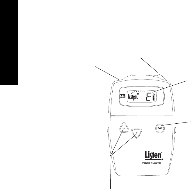
LT-700 Front
3.5mm Input Jack
A Listen microphone or line
level cable connects here.
MUTE / TALK switch
(more information on page 5)
Power Switch
Press PWR switch to turn unit
on. Press and hold to turn
unit off. When in PROGRAM
mode, this switch is used to
toggle the lock out (L/O)
mode for a channel.
Press and hold both buttons for 5 seconds to enter PROGRAM
mode. The PGM icon will appear in the display. To exit PROGRAM,
let unit sit idle for 5 seconds.
Use UP and DOWN buttons to select a channel.
Press and hold either button for 5 seconds to
lock the channel. Press and hold either button
again to unlock.
Look & Listen Display™
The display shows level, channel,
battery status, PROGRAM mode,
whether a channel is locked, and
whether a channel is locked out
from selection (PROGRAM mode).
See close-up on page 6.
Quick Reference
5
Quick Reference
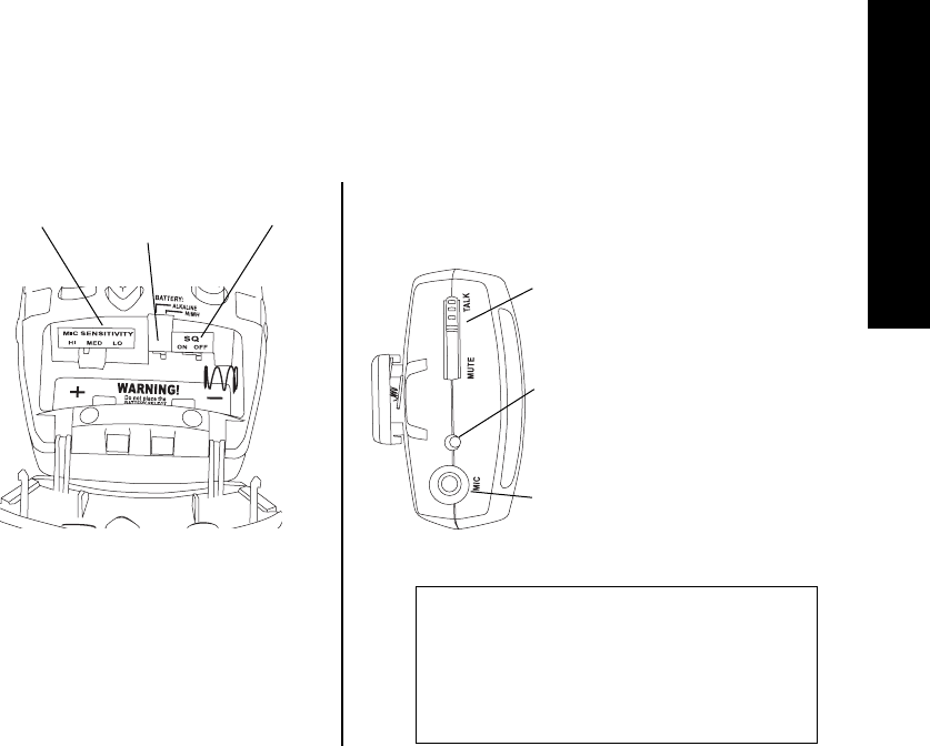
LT-700 Inside Access Door
Mic Sensitivity Switch - it arrives set at MID, which will
work for most microphones. If your mic level is too low,
change the switch to HI; if the level is too high, switch to
LO. (see page 8 for more information)
Battery Select Switch - place in NiMH position ONLY if you
are using Nickel Metal Hydride batteries, otherwise, leave it
in the Alkaline position.
SQ Switch: shipped in the ON position, use a screwdriver
or pen to slide to the OFF position if needed. You should
turn SQ off if you are using any non Listen receiver or older
Listen receiver that does not have the SQ feature. (see
page 20 for more information)
Mic Sensitivity
Switch SQ Switch
Battery Select
Switch
3.5mm Input Jack
A microphone or line level cable connects here.
LED indicators:
Steady Red:
Normal operation
Slow Flashing:
Battery is low
Slow Flashing while charging:
Unit is charging
Fast Flashing:
Mute
MUTE / TALK switch - this mutes the mic
only and not the line input when in the mute
position.
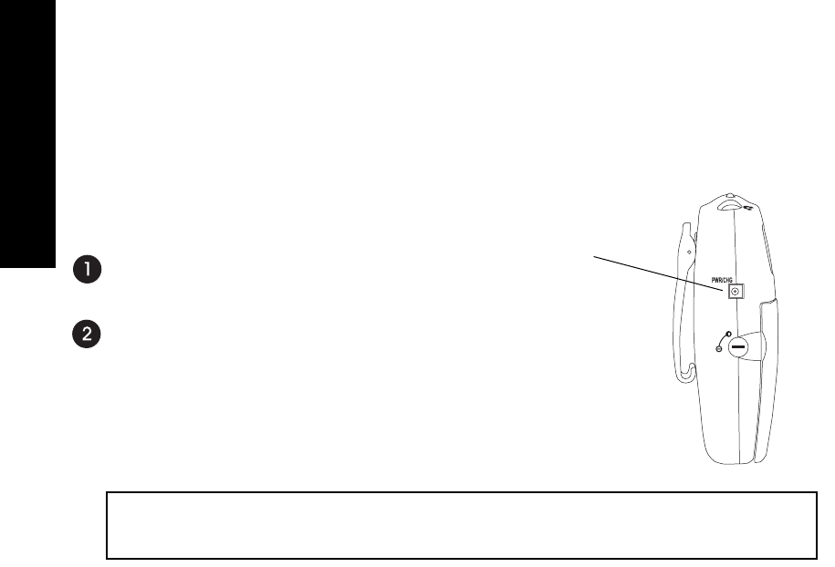
LT-700 Top of Unit
A Note on Charging NiMH Batteries
If you are using NiMH batteries in any Listen
product, you should allow adequate time
for the charger (charging case or LA-202)
to complete a full charge cycle on the
batteries. This takes about 13 hours.
Quick Reference
6
Quick Reference
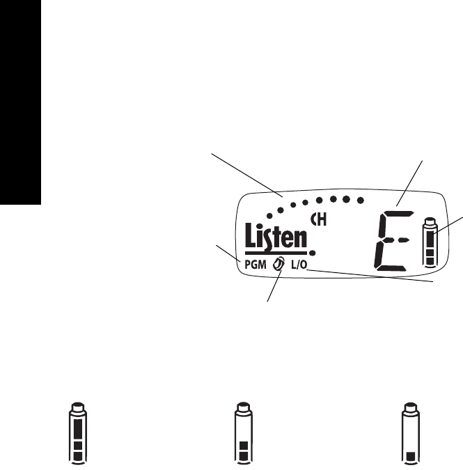
LT-700 Look & Listen™ Display
When dots are illuminated, the microphone
is active. If this display does not appear,
the microphone is muted.
Indicates the currently
tuned channel
Indicates the unit is in PROGRAM mode
(see next page). To enter PROGRAM
mode, press and hold the UP and DOWN
keys until the PGM icon appears in the dis-
play. To exit PROGRAM mode, let the unit
sit idle for 5 seconds. If the padlock icon is visible, the channel is
locked. Press and hold either the UP and
DOWN button for 5 seconds to lock or
unlock.
When in the PROGRAM mode, L/O
indicates whether a particular channel
is locked out.
Battery level indicator. The indi-
cator flashes, along with the red
LED on top of the unit, to alert
you when the battery is low and
needs to be charged or
changed. (see information
below)
All three segments showing:
The batteries are at 50% or
greater capacity.
One segment showing:
Your batteries less than 25% capacity. When
this segment begins flashing along with the
LED on top of the unit, you should immedi-
ately change your batteries or recharge them
(if using NiMH batteries).
Two segments showing:
The batteries are at 25-49%
capacity.
LT-700 Battery Indicator
Setup Instructions
7
LT-700 Setup Instructions
Remove the product
Remove outer packaging and plastic cover. Inspect for physical damage. If damage is aparent,
please contact Listen Technologies Corporation technical support
for assistance. See page 29 for contact information.
Open the front access door
If locked, use a pocketknife or small screwdriver to unlock the door
locks on both sides of the unit. To unlock the door, rotate the lock
¼ turn counterclockwise.
Grip the two tabs with your thumb and index finger and pull the
door downward. Do NOT place batteries in the unit yet.
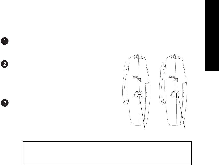
Select Battery Type
See diagram on page 8. You have two choices: NiMH and Alkaline.
The unit is shipped with the switch in the Alkaline position. Use a
pen or small screwdriver to select the battery type.
CAUTION: If you are using any battery type other than
rechargeable Nickel Metal Hydride (NiMH) batteries, make sure the
BATTERY selection switch is in the alkaline position.
LockedUnlocked
WARNING: Do not place the BATTERY switch in the NiMH position if you are not using
Nickel Metal Hydride Batteries. The NiMH position will attempt to charge any batteries
in the unit, even if they are not the proper type. Charging non-Nickel Metal Hydride
(NiMH) batteries will result in physical harm, destruction of property and/or fire.
Setup Instructions
8
LT-700 Setup Instructions continued
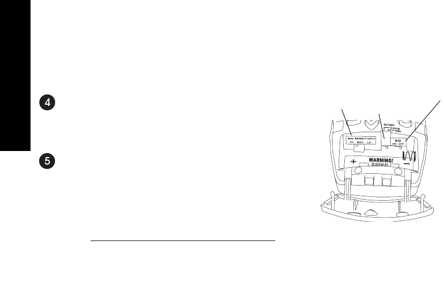
Set SQ switch
The SQ switch is inside the battery compartment next to the Battery
Select switch. The unit is shipped with SQ in the ON position. To turn it
off, use a small screwdriver or pen to slide the switch to the OFF position
(to the right). See page 20 for more information on SQ.
Set Mic Sensitivity Switch
The microphone sensitivity switch is located inside the battery compart-
ment, to the left of the BATTERY selection switch. The LT-700 is shipped
with this switch in the center (MED) position. Listen recommends the
following settings for our microphones. If you are using a microphone from
another vendor, you may need to experiment with different settings.
Part # Description Setting
LA-261 Lavalier Microphone MED
LA-262 Over-the-Head Microphone MED
LA-268 Over-the-Ear Microphone MED
LA-270 Noise Cancelling Microphone MED
LA-277 Confrerence Microphone MED
LA-272 Over-the-Head Mic w/Earphone MED
LA-273 Over-the-Ear Mic w/Earphone MED
LA-278 Behind-the-Head Microphone MED
LA-274 Handheld Microphone HI
LA-276 Collar Microphone HI
NOTE: If the setting is too low for
the microphone in use the audio will
be faint. If the setting is too high for
the microphone in use the audio will
be distorted.
Battery Select
Switch
Mic Sensitivity
Switch SQ Switch
Setup Instructions
9
LT-700 Setup Instructions continued
Place Batteries in Unit
Place two AA batteries in the compartment, making note of the battery polarity shown in the
battery compartment, and again verifying that the BATTERY SELECT switch is in the cor-
rect position for the batteries you are using. (ALK should be selected for all battery types
other than NiMH).
NOTE: Listen uses 1800mAh (milli-Amp-hour) constant current NiMH (Nickel Metal
Hydride) batteries. These may be purchased from your Listen dealer (ask for part number LA-
362).
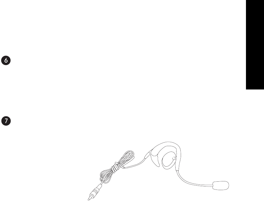
Connect the Microphone
The microphone jack is located on top of the unit. The LT-700 uses the microphone cable as
an antenna for transmitting.
LA-268 Over-the-Ear Microphone
Setup Instructions
10
LT-700 Setup Instructions continued
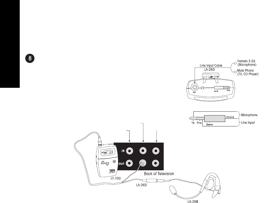
Optional - Connect the Line Input Cable.
This cable allows you to connect a TV, CD player or other equipment to
the LT-700. To do this, you must order the Listen LA-263 Line Input
Cable (it is not included with your unit). This cable allows you to con-
nect both a microphone and line input to the jack on top of the LT-700.
See the diagram below for connection information. You can use the
microphone and the line input at the same time. Please note that the
MUTE switch mutes only the microphone; the line source will continue
transmitting when the switch is in the MUTE position.
If you prefer to make your own cable for connection of mic and line inputs,
connect shown in the following diagram:
Stereo-Red
Mono-White Video-Yellow

Operating Instructions
11
LT-700 Operating Instructions
Make sure the unit is on
When you press the power button, the LED on top of the unit will be illuminated and the
LCD display will be visible.
Select the channel for transmitting
Please refer to Channel Selection on pages 18-19 for guidelines on choosing an interference-
free channel.
To select a channel, press either the channel UP or DOWN button until the display reads the
channel you want. To lock your selection, press and hold the UP or DOWN button for 5 sec-
onds. When locked, the small padlock icon will be visible on the display. Press and hold
either button again to unlock.
72MHz Units
The LT-700-072 operates on 17 wide band channels and 40 narrow band channels. Channels
represented by letters in the display (i.e. A) are wide band channels; channels represented by
numbers are narrow band channels.
216MHz Units
The LT-700-216 operates on 19 wide band channels and 38 narrow band channels. Channels
beginning with a “2” are wide band channels and channels beginning with a “1” or “3” are nar-
row band channels.
Listen recommends using wide band channels whenever possible, as they are not as noisy as
narrow band channels.
Refer to the Frequency Compatibility tables (pages 22-25) for specific frequencies and compati-
bility with other manufacturers. Also refer to pages 18-19 for more information on channel
selection.

LT-700 Operating Instructions continued
Close the Access Door
Lock it if desired by turning the locks on the side of the unit to the vertical position. See
diagram on page 7.
Using the red MUTE / TALK switch on top of the unit
The red mute/talk switch on top of the unit is a handy way to “turn off” the audio from the
microphone. Slide the switch to the mute position and the microphone audio is muted.
When the microphone audio is muted, the LED on top of the unit flashes rapidly. Slide the
switch back to the talk position and the microphone audio will return to the transmission. If
you are using line level audio, it will not be effected by the mute/talk switch.
Operating Instructions
12
LT-700 Shown in the TALK position

Programming
13
LT-700 Programming Instructions
The LT-700 can be programmed to transmit on a limited number of channels. For applications
where users are required to select a channel (such as classrooms or language interpretation),
and you don’t want them to have to scroll through all of the available channels, this feature is
ideal. You can set up the LT-700 so that only the channels they need to use are available for
selection with the UP and DOWN buttons.
Enter PROGRAM Mode
Press and hold the UP and DOWN keys simultaneously until the PGM symbol is displayed (see
the Look & Listen™ Quick Reference on page 6).
Scroll Through Channels to Lock or Unlock
Use the UP and DOWN channel select keys to scroll through all available channels. If the
L/O symbol appears with a particular channel’s indicator, this means that particular channel
will not be available for selection by the user. To toggle a channel between locked out and
available, press the POWER button.
To exit PROGRAM mode
Allow the unit to sit idle (don’t press any buttons) for 5 seconds. The LT-700 will exit the
PROGRAM mode and the PGM icon will disappear.
LT-700 Charging Batteries
The LT-700 and all Listen receivers are unique because they have
SmartCharge™ chargers built in. When any of these units are connected
to an LA-202 wall transformer or dropped into a Listen charging case,
NiMH batteries will be charged.
To charge the batteries using the LA-202 wall transformer, plug the trans-
former into the jack marked “PWR/CHG” on the side of the unit. The
unit can be operated while the batteries are charging.
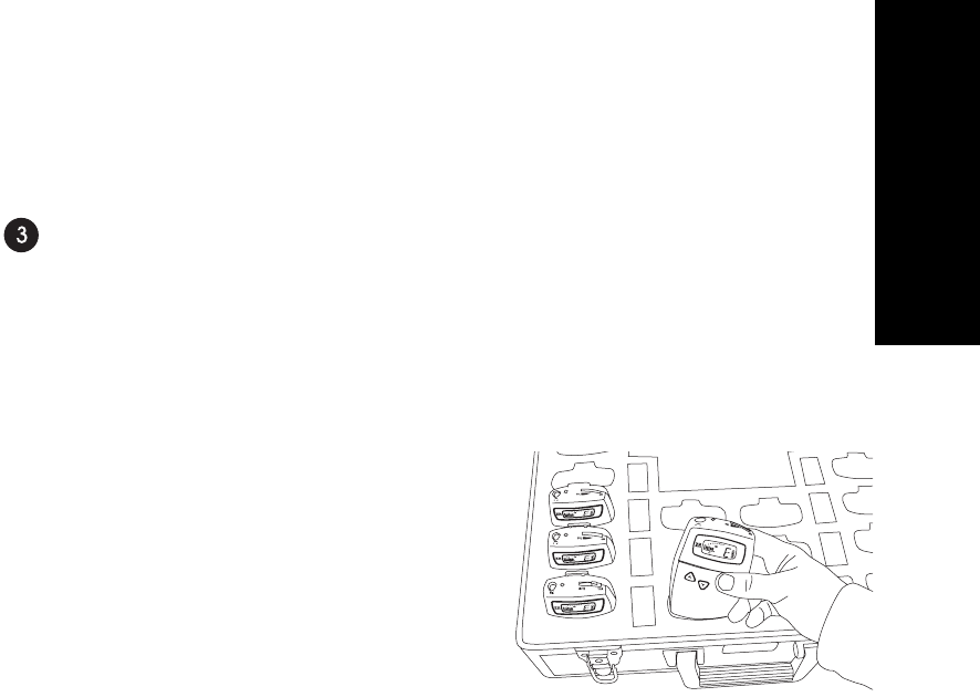
To charge the batteries using a drop-in charger, simply place the unit into a
slot in the charger and connect the charger to power. Make sure the unit is
fully seated in its slot.
One of several charging cases available from Listen. Check the Listen web-
site for more details.
SmartCharge™ uses a pulse charging, which greatly extends the life of
Nickel Metal Hydride (NiMH) batteries. The entire charging process takes
about 13 hours. Listen recommends that you allow the charger to complete
its full cycle every time for maximum battery life.
IMPORTANT: In order to charge NiMH batteries, the BATTERY SELECT switch in your
Listen product must be set to the NiMH setting. Use a pen or small screwdriver to move the
switch (located in the battery compartment) to the proper position.
Charging Batteries
14
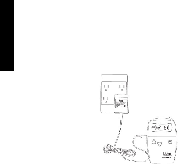
Connect LA-202
here and plug it
into an AC wall
outlet.
IMPORTANT: DO NOT ATTEMPT TO CHARGE ANY TYPE OF BATTERY OTHER THAN NiMH (NICKEL METAL
HYDRIDE) with your Listen equipment. Alkaline batteries may explode when connected to a
charger. Other risks of charging non-NiMH batteries include destruction of property or fire.
Charging Batteries
15
LT-700 Charging Batteries continued
During the charge cycle, the red LED on top of the Listen product will flash slowly. When
charging is completed, the LED will turn off. It is not necessary to unplug the charger; howev-
er, if you unplug the unit from the charger and then plug it back in, it will begin the 13-hour
charge cycle over again.
When not using the LT-700, it is recommended to leave the unit on the charger. The charger
provides a “maintenance” charge that keeps the battery at 100%. If the unit is not on the
charger, the battery will lose up to 20% of its charge per month.
NOTE: Listen uses 1800mAh (milli-Amp-hour) constant current NiMH (Nickel Metal
Hydride) batteries. These may be purchased from your Listen
dealer (ask for part number LA-362).
One of several charging cases
available from Listen. See
www.ListenTech.com for more
options.
LA-311 - 16-unit Drop In Charging Case shown
LT-700 Wall Transformer Operation
The LT-700 will operate normally when connected to a wall transformer. Use Listen part number
LA-202, available from any Listen dealer. Connect the wall transformer to the jack on the side of
the LT-700 marked “PWR/CHG” and plug the wall transformer into a grounded AC outlet.
You do not need to have batteries installed in the LT-700 to operate it with a wall transformer.
NOTE: If batteries are in the unit ensure
that the battery selection switch is set
properly as shown on page 5. Please
review the information on page 14 for
important information regarding battery
type and charging.
Wall Transformer Operation
16

Supplementary Information
17
Supplementary Information
Channel Selection . . . . . . . . . . . . . . . . . . . . . . . . . . . . . . . . . . . . . . . . . . . . . . . . . . . . . . . . .18
Listen SQ™ . . . . . . . . . . . . . . . . . . . . . . . . . . . . . . . . . . . . . . . . . . . . . . . . . . . . . . . . . . . . . .20
RF Reception Maximization Strategies . . . . . . . . . . . . . . . . . . . . . . . . . . . . . . . . . . . . . . . . .21
72 MHz Frequency Compatibility Table . . . . . . . . . . . . . . . . . . . . . . . . . . . . . . . . . . . . . . . .22
216 MHz Frequency Compatibility Table . . . . . . . . . . . . . . . . . . . . . . . . . . . . . . . . . . . . . . .24
Troubleshooting . . . . . . . . . . . . . . . . . . . . . . . . . . . . . . . . . . . . . . . . . . . . . . . . . . . . . . . . . . .26
Compliance Notice . . . . . . . . . . . . . . . . . . . . . . . . . . . . . . . . . . . . . . . . . . . . . . . . . . . . . . . .29
FCC Statement . . . . . . . . . . . . . . . . . . . . . . . . . . . . . . . . . . . . . . . . . . . . . . . . . . . . . . . . . . .30
Warranty . . . . . . . . . . . . . . . . . . . . . . . . . . . . . . . . . . . . . . . . . . . . . . . . . . . . . . . . . . . . . . . . .31
Optional Accessories . . . . . . . . . . . . . . . . . . . . . . . . . . . . . . . . . . . . . . . . . . . . . . . . . . . . . . .32

Channel Selection
18
Channel Selection
It is important to choose channels that are free from interference to achieve proper operation of
your Listen equipment. This process is trial and error. Before turning on the transmitter, listen to
the wide band channels (lettered channels at 72MHz and channels that start with a “2” for
216MHz when using a Listen receiver). Listen to the audio through the headphone or on a Listen
receiver or receiver / speaker. Choose a channel with the least amount of interface. Unless you
are interfacing with an existing narrowband transmission system, always use a wide band channel.
If you are using multiple channels follow this process:
a. Same Space If you are using multiple transmitters in the same space, the most number of
channels that will work simultaneously is six at 72MHz and three at 216MHz. With all of the
transmitters off, listen for interference on all the wide band channels via the headphone jack
on a Listen receiver. Using the frequency compatibility tables on pages 22-25, eliminate any
channels that have noticeable interference. Now choose the channels with the widest channel
spacing. It is recommended that adjacent channels be spaced at least 300kHz. If there is no
interference the following channels are recommended: A, C, E, I, J, and H for 72MHz and
channels 2A, 2K and 2V at 216MHz.
b. Distributed Spacing If you are using transmitters that are spread out over space, you can
achieve more simultaneous broadcast channels. However, it is critical that your receiver(s) be
located as close to its transmitter as possible. You can use adjacent channels (see frequency
compatibility tables on pages 22-25) in this case as long as the adjacent channel transmitter is
at least 50% further away from the receiver as its transmitter. Example: The transmitter for
the receiver on channel E is 100 feet from the receiver. The adjacent channel transmitter on
channel D should be at least 150 feet away.

Channel Selection
19
It is highly recommended that after channel selection has been achieved, you
lock the channel so that it cannot be changed by the user. To accomplish LOCK
on the LT-800, press both the UP and DOWN buttons simultaneously for 5 sec-
onds. Repeat the process to unlock.
Notes in regard to using 72MHz and 216MHz systems:
i. 72MHz in a secondary frequency band. This means that other transmitters
are licensed to use these frequencies. Thus, you may experience interference
from paging transmitters and other types of transmissions. You will need to
find a clear channel by listening to all the wide band channels.
ii. 216MHz is a primary frequency band and no other types of transmissions are
authorized to use it. Thus, you will find the highest probability of clear chan-
nels in this band. However, you may experience intermodulation of the TV
Channel 13 aural carrier if there is a channel 13 transmitter in your area and
you are close to the transmitter. If you cannot find a clear channel in
216MHz band due to channel 13, it is recommended that you switch to a
72MHz system.
Channel Selection continued
Wide Band Recommendation
Listen recommends that you always use a
wide band channel unless you need to be
compatible with existing narrow band
receivers from other manufacturers.
Wide band channels have lower noise
than their narrow band counterparts.
At 72MHz
The LT-800 at 72MHz operates on 17
wide band channels and 40 narrow band
channels.
· Letters= Wide Band Channels
(Example: E)
· Numbers= Narrow Band Channels
(Example: 32)
At 216MHz
The LT-800 at 216MHz operates on 19
wide band channels and 38 narrow band
channels.
· “2” as left digit= Wide Band Channel
(Example: 2C)
· “1” and “3” as left digits= Narrow
Band Channels (Examples: 1A; 3R)

Listen SQ™
20
Listen SQ™
We are accustomed to listening to low noise, high fidelity audio (delivered via
CD, DVD, etc.). FM radio systems, such as those made by Listen, have more
inherent noise compared to most sound systems. To reduce noise of our sys-
tems, Listen uses a noise reduction technology called ListenSQ™. Both the
transmitter and receiver must have the SQ feature enabled to achieve the
desired results. SQ is available on new Listen systems, including the system
you received in this shipment. If you are planning to use this product with
older Listen systems that do not have Listen SQ or equipment not manufac-
tured by Listen, you should disable Listen SQ.
Your Listen equipment has been shipped to you with the SQ feature enabled.
You may need to disable the SQ function for one or more of the following rea-
sons:
1. You are using your new Listen system with older version Listen equipment
that does not have the SQ function.
2. You are using your new Listen system with equipment supplied by other
manufacturers.
3. You expect that end users may bring and use their own receivers that don’t
have the SQ function.
SQ Summary
· Improves noise performance by at
least 20dB
· SQ is NOT compatible with older
version Listen products
· SQ is NOT compatible with other
manufacturers’ products
· SQ is NOT squelch
· To work properly, SQ must be
enabled for both the transmitter
and receivers
· SQ can be disabled to permit oper-
ation with older Listen products or
other manufacturers’ products

RF Reception Strategies
21
For proper and dependable operation, Listen receivers should receive a strong and consistent signal
from the originating transmitter. The following strategies should be used maximize this signal:
a. When using your system, keep in mind that the location of both the transmitter and receiver is
critical to maximizing signal strength.
b. Eliminate or minimize obstructions between the transmitter and the receivers.
c. Minimize the distance between the transmitter and the receivers.
d. Stay clear of metal objects.
e. Keep the microphone and headphone cables fully extended. Do not shorten or coil
microphone and headphone cables. These cables are the antennas for you portable products.
NOTE: If the RF signal to the 216MHz model receivers is too high, the audio will be distorted.
This may happen if you are within 5 feet of the 216MHz transmitter.
RF Reception Maximization Strategies

72MHz Compatibility Chart
22
72MHz Compatibility Chart
Frequency
MHz
Listen
Phonic
Ear
Comtek Phonak Williams* Gentner Telex Drake
72.0250 111A1 (11, 1)
72.0500 (2) 1
72.0750 222A2 (12, 3)
72.1000 AAAAA, (13, 4) 2 A 72.1
72.1250 333A3 (14, 5)
72.1500 (6) 3
72.1750 444A4 (15, 7)
72.2000 KKKKK, (8) 4 B 72.2
72.2250 555K5 (16, 9)
72.2500 (10) 5
72.2750 666K6 (17, 11)
72.3000 BBBBB, (18, 12) 6 C 72.3
72.3250 777B7 (19, 13)
72.3500 (14) 7
72.3750 888B8 (20, 15)
72.4000 NNNNN, (16) 8 D 72.4
72.4250 999N9 (21, 17)
72.4500 (18) 9
72.4750 10 10 10 N0 (22, 19)
72.5000 CCCCC, (23, 20) 10 E72.5
72.5250 11 11 11 C1 (24, 21)
72.5500 (22) 11
72.5750 12 12 12 C2 (25, 33)
72.6000 OOOOO, (24) 12 F72.6
72.6250 13 13 13 O2 (26, 25)
72.6500 (26) 13
72.6750 14 14 14 4(27)
72.7000 DDDDD, (28) 14 G72.7
72.7250 15 15 15 D5 (29)
72.7500 (30) 15
72.7750 16 16 16 D6 (30, 31)
72.8000 PPPPP, (32) 16 H72.8
72.8250 17 17 17 P7 (31, 33)
72.8500 (34) 17
72.8750 18 18 18 P8 (32, 35)
72.9000 EEEEE, (33, 36) 18 I72.9
72.9250 19 19 19 E9 (34, 37)
72.9500 (38) 19
72.9750 20 20 20 E0 (35, 39)
Wide band frequencies in shaded sections
*Parenthesis indicate T35 and T20 narrowband.
Chart continued on next page

72MHz Compatibility Chart
23
72MHz Compatibility Chart continued
74.6250 33 33 33 E3 (36, 40)
74.6500 (41) 20
74.6750 34 34 34 E4 (37, 42)
74.7000 IIIII, (38, 43)21O
74.7250 35 35 35 I5 (39, 44)
74.7500 (45) 22
74.7750 36 36 36 I6 (40, 46)
75.2250 37 37 37 I7 (41, 47)
75.2500 (48) 23
75.2750 38 38 38 I8 (42, 49)
75.3000 JJJJJ, (43, 50)24P
75.3250 39 39 39 J9 (55, 51)
75.3500 (52) 25
75.3750 40 40 40 J0 (45, 53)
75.4000 RRRRR, (54)26Q
75.4250 21 21 21 R1 (46, 55)
75.4500 (56) 27
75.4750 22 22 22 R2 (47, 57)
75.5000 FFFFF, (48, 58)28J75.5
75.5250 23 23 23 F3 (49, 59)
75.5500 (60) 29
75.5750 24 24 24 F4 (50, 61)
75.6000 SSSSS, (62)30K75.6
75.6250 25 25 25 S5 (51, 63)
75.6500 (64) 31
75.6750 26 26 26 S6 (52, 65)
75.7000 GGGGG, (53, 66)32L75.7
75.7250 27 27 27 G7 (54, 67)
75.7500 (68) 33
75.7750 28 28 28 G8 (55, 69)
75.8000 TTTTT, (70)34M75.8
75.8250 29 29 29 T9 (56, 71)
75.8500 (72) 35
75.8750 30 30 30 T0 (57, 73)
75.9000 HHHHH, (58, 74)36N75.9
75.9250 31 31 31 H1 (59, 75)
75.9500 (76) 37
75.9750 32 32 32 H2 (60, 77)
Frequency
MHz
Listen
Phonic
Ear
Comtek Phonak Williams* Gentner Telex Drake
Wide band frequencies in shaded sections
*Parenthesis indicate T35 and T20 narrowband.

216MHz Compatibility Chart
24
216MHz Compatibility Chart
Frequency
MHz
Listen
Phonic
Ear
Comtek Phonak Williams Gentner CSI AVR
Light
Speed
216.0125 1A 1 1 C01 N01
216.0250 2A 41 41 41 1 1
216.0375 3A 2 2
216.0625 1B 3 21
216.0750 2B 42 42 42 2 10
216.0875 3B 4 4
216.1125 1C 5 5 C05
216.1250 2C 43 43 43 A 3 6
216.1375 3C 6 22
216.1625 1D 7 23
216.1750 2D 44 44 44 B 4 14
216.1875 3D 8 8
216.2125 1E 9 9 C09 N09
216.2250 2E 45 45 45 C 5 2
216.2375 3E 10 24
216.2625 1F 11 25
216.2750 2F 46 46 46 D 6 11
216.2875 3F 12 12 C12 N12
216.3125 1G 13 13
216.3250 2G 47 47 47 E 7 7
216.3375 3G 14 26
216.3625 1H 15 27
216.3750 2H 48 48 48 F 8 15
216.3875 3H 16 16 C18 N18
216.4125 1J 17 17 C21
216.4250 2J 49 49 49 G 9 18
216.4375 3J 18 18
216.5125 1K 21 61
216.5250 2K 51 51 29 H 10 3
Wide band frequencies in shaded sections
Chart continued on next page

216MHz Compatibility Chart
25
216MHz Compatibility Chart continued
216.5375 3K 22 62
216.5625 1L 23 28
216.5750 2L 52 52 52 I 11 12
216.5875 3L 24 64 C24 N64
216.6125 1M 25 65 C25
216.6250 2M 53 53 53 J 12 8
216.6375 3M 26 81
216.6625 1N 27 82
216.6750 2N 54 54 54 K 13 16
216.6875 3N 28 68
216.7125 1P 29 69 C29
216.7250 2P 55 55 55 L 14 19
216.7375 3P 30 83
216.7625 1R 31 84
216.7750 2R 56 56 56 15 4
216.7875 3R 32 72 C32 N72
216.8125 1S 33 73 C33
216.8250 2S 57 57 57 13
216.8375 3S 34 76
216.8625 1T 35 85
216.8750 2T 58 58 58 9
216.8875 3T 36 86
216.9125 1U 37 77 C37 N77
216.9250 2U 59 59 59 17
216.9375 3U 38 88
216.9625 1V 39 79 C39
216.9750 2V 60 60 60 5
216.9875 3V 40 80 C40 N80
Frequency
MHz
Listen
Phonic
Ear
Comtek Phonak Williams Gentner CSI AVR
Light
Speed
Wide band frequencies in shaded sections

Troubleshooting
26
LT-700 Troubleshooting
The LT-700 has no power
Make sure the unit has fully charged batteries, or has a Listen LA-202 wall transformer connected
to it. Press the ON button. If this does not work, try a different set of batteries. Make sure the
batteries are installed correctly.
There is no audio
Make sure the MUTE/TALK switch is in the TALK position. Make sure you have the microphone
plugged all the way in to the input jack. Make sure you are using a Listen approved microphone
(see list on page 8). If you are using the line input, make sure you have connected a line level,
unbalanced input at the “ring” of the connector.
The audio is distorted
Make sure you are using an approved Listen microphone. Try using a different mic sensitivity
switch setting (the switch is located inside the battery compartment of the unit). If you are using a
line level input, try turning down the level of the input. If you are using any equipment that does
not have SQ capability, turn off SQ in the LT-700.
There is hum in the audio
The microphone may be too close to a transformer. Try moving around and see if the hum goes
away.
The microphone level is low
The microphone must be in close proximity to the person who is speaking. If this does not work,
try using a head-worn microphone. The mic sensitivity switch may be on the wrong setting, see
page 8. Try a different setting (the switch is located inside the battery compartment).
Some microphones have directional pickups, ensure that the microphone in use is oriented and
positioned properly (pointing at the speakers mouth).

Troubleshooting
27
LT-700 Troubleshooting continued
The audio doesn’t have much fidelity
If your receivers all have SQ capability, activate SQ in all units by moving their switches to the
ON position. In the LT-700 and all SQ-equipped receivers, the SQ switch is located inside the bat-
tery compartment. See page 20 for more information.
There is too much noise
This is most likely because the microphone is not close enough to the talker’s mouth, and it is pick-
ing up background noise. Try positioning the microphone closer or try using a microphone that is
directional (such as a head-worn mic). If you are using a narrow band channel, try switching to a
wide band channel. Try another setting on the mic sensitivity switch (located inside the battery
compartment). Ensure the microphone is not brushing up against anything. See page 8 for more
information.
There is interference
Try different frequencies until you find a clear channel. If this does not work, try a different fre-
quency band (i.e. if you are using 72MHz equipment, exchange it for 216MHz equipment). This is
done by returning the equipment to Listen (no charge) and swapping it for the alternate frequency
band equipment.
I cannot pick up the signal on the receiver
Make sure the transmitter and the receiver are on the same frequency band (72MHz or 216MHz)
and channel.
I can pick up the signal on the receiver, but it sounds like it’s not tuned in
Check to make sure the transmitter and receiver are on exactly the same channel number / letter.
If using another brand of receiver refer to Listen’s Frequency Compatibility Tables on pages 22-25).

Troubleshooting
28
LT-700 Troubleshooting continued
There is not sufficient range
The LT-700 is a portable transmitter that uses the microphone cable as an antenna and the range
will vary depending on the location of the receivers compared to the transmitter. You can only
expect about 100 feet of average effective working range.
It’s confusing for users to have 57 channels when switching between
channels
Use the PROGRAM function to lock out unwanted channels. This way, users will only need to
scroll among a few channels.
I cannot change the channel
It is probably locked (check for the padlock icon). To unlock, press and hold the UP or DOWN
button for 5 seconds.
My batteries are not charging
Make sure you are using NiMH batteries and that the BATTERY SELECT switch (inside the bat-
tery compartment) is set to the NiMH position. Make sure the batteries are installed correctly.
Make sure you are using the right kind of wall transformer (Listen part number LA-202) or charg-
ing case. Make sure the charging case is connected to power and the unit is securely pushed into
its slot in the case.
NOTE: Listen uses 1800mAh (milli-Amp-hour) constant current NiMH (Nickel Metal Hydride)
batteries. These may be purchased from your Listen dealer (ask for part number LA-362).

Compliance Notice
29
Compliance Notice
This device complies with part 15 of the FCC Rules. Operation is subject to the following two
conditions: (1) These devices may not cause harmful interference, and (2) these devices must
accept any interference received, including interference that may cause undesirable operation.
Listen’s LT-700 Transmitter (216MHz only)
Listen’s LT-700 transmitter is authorized by rule under the Low Power Radio Service (47 C.F.R.
Part 95) and must not cause harmful interference to TV reception or United States Navy SPASUR
installations. You do not need an FCC license to operate these transmitters. These transmitters
may only be used to provide: auditory assistance to persons with disabilities, persons who require
language translation, or persons in educational settings; health care services to the ill; law enforce-
ment tracking services under agreement with a law enforcement agency; or automated maritime
telecommunications system (AMTS) network control communications. Two-way voice communi-
cations and all other types of uses not mentioned above are expressly prohibited.
CAUTION: Changes or modifications not expressly approved by the party responsible for compli-
ance could void the user’s authority to operate Listen’s equipment.

FCC Statement
30
FCC Statement
This equipment has been tested and found to comply with the limits for a class B digital device,
pursuant to part 15 of the FCC Rules. These limits are designed to provide reasonable protection
against harmful interference in a residential installation. This equipment generates, uses and can
radiate radio frequency energy and if not installed and used in accordance with the instructions,
may cause harmful interference to radio communications. However, there is no guarantee that
interference will not occur in a particular installation. If this equipment does cause harmful inter-
ference to radio or television reception, which can be determined by turning the equipment off and
on, the user is encouraged to try to correct the interference by one or more of the following meas-
ures:
· Reorient or relocate the receiving antenna.
· Increase the separation between the equipment and receiver.
· Connect the equipment into an outlet on a circuit different from that to which the receiver is
connected.
· Consult the dealer or an experienced radio/TV technician for help.
This equipment has been certified to comply with the limits for a class B computing device, pur-
suant to FCC and IC Rules. In order to maintain compliance with FCC and IC regulations, shield-
ed cables must be used with this equipment. Operation with non-approved equipment or unshield-
ed cables is likely to result in interference to radio and TV reception. The user is cautioned that
changes and modifications made to the equipment without the approval of manufacturer could
void the user’s authority to operate this equipment.

Warranty
31
Warranty
Listen Technologies Corporation (Listen®) warrants the LT-700 Portable Transmiter to be free
from defects in workmanship and material under normal use and conditions for the useful lifetime
of the product from date of purchase. This warranty is only available to the original end purchaser
of the product and cannot be transferred. Warranty is only valid if warranty card has been returned
within 90 days of purchase. This warranty is void if damage occurred because of misuse or if the
product has been repaired or modified by anyone other than a factory authorized service techni-
cian. Warranty does not cover normal wear and tear on the product or any other physical damage
unless the damage was the result of a manufacturing defect. Listen is not liable for consequential
damages due to any failure of equipment to perform as intended. Listen shall bear no responsibility
or obligation with respect to the manner of use of any equipment sold by it. Listen specifically dis-
claims and negates any warranty of merchantability or fitness of use of such equipment including,
without limitation, any warranty that the use of such equipment for any purpose will comply with
applicable laws and regulations. The terms of the warranty are governed by the laws of the state of
Utah, USA. Listen will only accept returned products with prepaid shipping and with a return
authorization number. To receive a return authorization number call 1.800.330.0891 or
+1.801.233.8992. Please see www.ListenTech.com or contact Listen for complete warranty details.
Optional Accessories
32
Optional Accessories
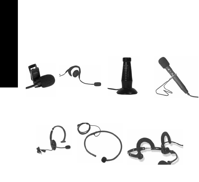
LT-700 Microphones
Over-the-Ear
LA-268
Lavalier
LA-261
Conference
LA-277
Over-the-Head
LA-262
Collar
LA-276
Noise Canceling
LA-270
Hand Held
LA-274
Optional Accessories
33
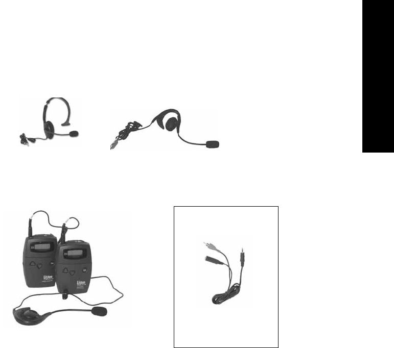
Optional Accessories
These headsets combine cabling for both a
transmitter and a receiver
Over-the-Head Mic
with Earphone
LA-272
Over-the-Ear Mic with
Earphone
LA-273
Use Both an Audio
Source and Mic
Line/Microphone
“Y” Cable
LA-263
Microphones with Active Earphones

Notes
34

Notes
35

Listen Technologies Corporation
8535 South 700 West, Suite A
Sandy, Utah 84070-2515 USA
Telephone: +1.801.233.8992
Toll Free (North America): 1.800.330.0891
Fax: +1.801.233.8995
E-mail: info@ListenTech.com