Lmms Linux Multimedia Studio Computer Accessories Mint V4 Pc Programming Guide Users Manual
2015-02-09
: Lmms Lmms-Lmms-Linux-Multimedia-Studio-Computer-Accessories-Mint-V4-Pc-Programming-Guide-Users-Manual-575332 lmms-lmms-linux-multimedia-studio-computer-accessories-mint-v4-pc-programming-guide-users-manual-575332 lmms pdf
Open the PDF directly: View PDF ![]() .
.
Page Count: 88

MN1278 05.2001
Mint™ version 4
PC Programming Guide
MN1278
Issue 1.2

Mint v4 PC Programming Guide
ii MN1278 05.2001

Copyright
MN1278 05.2001 iii
Copyright Baldor UK Ltd © 2001. All rights reserved.
This manual is copyrighted and all rights are reserved. This document or attached software may not, in whole or in part, be copied or
reproduced in any form without the prior written consent of Baldor UK.
Baldor UK makes no representations or warranties with respect to the contents hereof and specifically disclaims any implied warranties of
fitness for any particular purpose. The information in this document is subject to change without notice. Baldor UK assumes no
responsibility for any errors that may appear in this document.
MINT™ is a registered trademark of Baldor UK Ltd.
Windows 95, Windows 98 and Windows NT are registered trademarks of the Microsoft Corporation.
Baldor UK Ltd
Mint Motion Centre
6 Bristol Distribution Park
Hawkley Drive
Bristol
BS32 0BF
U.K.
Telephone: +44 (0) 1454 850 000
Fax: +44 (0) 1454 859 001
Web site: www.baldor.co.uk
Sales email: sales@baldor.co.uk
Support email: technical.support@baldor.co.uk
Baldor Electric Company
Telephone: +1 501 646 4711
Fax: +1 501 648 5792
email: sales@baldor.com
web site: www.baldor.com
Baldor ASR GmbH
Telephone: +49 (0) 89 90508-0
Fax: +49 (0) 89 90508-492
Baldor ASR AG
Telephone: +41 (0) 52 647 4700
Fax: +41 (0) 52 659 2394
Australian Baldor Pty Ltd
Telephone: +61 2 9674 5455
Fax: +61 2 9674 2495
Baldor Electric (F.E.) Pte Ltd
Telephone: +65 744 2572
Fax: +65 747 1708

Mint v4 PC Programming Guide
iv MN1278 05.2001

Manual Revision History
MN1278 05.2001 v
Manual Revision History
Issue Date BOCL
Reference Comments
1.0 Apr 99 UM00545-000 Raised from MN00249-003.
This is a new UM for v4, allowing updates to the v3
manual to continue as MN00249-XYZ
1.1 Feb 00 UM00545-001 Added NextMove PC device driver documentation.
Corrected for Mint v4 ( new C++ files, Win2000,
WinME.
1.2 May 2001 UM00545-002 Updates for PC Developer Libraries 1302 release.

Mint v4 PC Programming Guide
vi MN1278 05.2001

Contents
MN1278 05.2001 vii
Introduction ................................................................................1
1.1 Introduction...............................................................................................2
1.2 Installation ................................................................................................2
Communicating with a Controller .............................................3
2.1 NextMove PCI...........................................................................................4
2.2 NextMove PC............................................................................................4
2.3 Dual Port RAM on NextMove PCI and PC ................................................4
2.4 Mint Comms Array (All Controllers)...........................................................5
2.5 Interfacing with Mint..................................................................................7
2.5.1 Preventing Deadlock Situations............................................................7
Using the Library with Various Languages..............................9
3.1 C++.........................................................................................................10
3.1.1 C++ : the Classes...............................................................................10
3.1.2 Pre-Compiled Headers in Visual C++ 6.0...........................................11
3.1.3 A Visual C++ 6.0 Tutorial ...................................................................14
3.1.4 Compiling an ATL COM Project with Visual C....................................24
3.1.5 RS485 Networks. ...............................................................................24
3.2 All Other Languages : The ActiveX Control ( OCX ) ...............................24
3.2.1 The ActiveX Control And The Languages It Can Be Used With. ........24
3.2.2 The ActiveX Control and Error Handling.............................................25
3.2.3 The ActiveX Control and Serial Controllers. .......................................25
3.2.4 The ActiveX Control and RS485 Networks.........................................25
3.2.5 Distributing an Executable Which Uses The ActiveX Control. ............25
3.2.6 ‘Server Busy” / “Component Request Pending” Errors. ......................25
3.3 Visual Basic 6.........................................................................................27
3.3.1 Error number conversion....................................................................27

Mint v4 PC Programming Guide
viii MN1278 05.2001
3.3.2 A Visual Basic Tutorial. ......................................................................27
3.4 Borland Delphi 5.0 ..................................................................................31
PC Based Motion Control ........................................................35
4.1 Limitations of PC based applications ......................................................37
4.2 Events and Interrupt Control on NextMove PCI ......................................38
4.2.1 Writing and Installing an Interrupt Handler .........................................38
4.2.2 Event Control Functions.....................................................................42
4.2.3 Interrupting the Host from a Mint Program ( DPR Events ).................43
4.2.4 Handling Events Using the ActiveX Control........................................43
NextMove PCI and Non-Microsoft Operating Systems..........45
5.1 How to Recognise the NextMove PCI.....................................................46
5.2 Host Accessible Hardware on NextMove PCI. ........................................46
5.3 The CSimplePCI class............................................................................46
5.3.1 The CMySimplePCI Example. ............................................................47
5.3.2 Functions Required by the Overloaded Class. ...................................47
5.3.3 Files to Include in a CSimplePCI Derived Class Project. ....................49
Appendix 1: DPR Map ..............................................................51
6.1 NextMove PCI DPR Map ........................................................................51
6.2 NextMove PC DPR Map .........................................................................54
6.3 Status and Control Registers..................................................................56
6.4 Axis Data ................................................................................................59
6.5 I/O Data ..................................................................................................61
6.6 Comms Array..........................................................................................62
6.7 Immediate Comand Mode.......................................................................62
6.8 Pseudo Serial Interface ..........................................................................63
6.9 Special Functions Registers ...................................................................64

Contents
MN1278 05.2001 ix
6.10 Data Synchronisation..............................................................................66
Appendix 2: Timings ................................................................67
7.1 Immediate Command Mode Functions ...................................................67
Appendix 3: Symbolic Constants............................................69
Bibliography .............................................................................77

Introduction
MN1278 05.2001 1
1. Introduction
1
The Mint™ v4 PC Programming Guide details how to call Mint v4
functions and how to communicate with Mint controllers from PC based
host applications.

Mint v4 PC Programming Guide
2 MN1278 05.2001
1.1 Introduction
The PC Developer Libraries allow PC based applications to be written that communicate with Mint controllers.
This is achieved using the Mint Interface Library which is a common API (Application Program Interface) for the
range of Mint based motion controllers. The Mint Interface Library is suitable for use under Windows 95, 98,
ME, NT and 2000 via an ActiveX control or C++ source code.
Features include:
• Ability to upload and download Mint programs and configuration files.
• Ability to interrogate the Mint command line.
• Updating of new firmware into FLASH or RAM.
• Support for the Mint Comms Protocol, whereby data can be transferred to an executing Mint program by
means of a protected datapacket.
• Ability to read Dual Port RAM locations on the NextMove PCI and NextMove PC (Mint v4)
controllers.
• PC based motion control.
• Support for communications with controllers on a CAN network.
Support is provided for the following controllers:
• NextMove product family: NextMove PCI, NextMove BX and NextMove PC.
• MintDrive.
• ServoNode 51.
• EuroSystem product family: SmartMove, SmartStep, EuroSystem, EuroStep, EuroServo.
This manual does not include detail on individual Mint Interface Library functions. Details can be found in the
Mint v4 Function Reference Guide.
1.2 Installation
From the Baldor Motion Toolkit CD, the ‘PC Developer Libraries’ should be installed from the NextMove PCI,
NextMove BX v4, MintDrive and ServoNode 51 product pages. This will install the ActiveX component, the
C++ source files and the examples. A custom setup option is also included to allow selective install of the
components.

Communicating with a Controller
MN1278 05.2001 3
2. Communicating with a Controller
2
This chapter covers general communication with Mint controllers.

Mint v4 PC Programming Guide
4 MN1278 05.2001
The Mint Interface Library is a common API that allows access to Mint controllers. It can be used via an
ActiveX control or through C++ source code. The Mint Interface Library is suitable for use under Windows 95,
98, ME, NT and 2000.
The ActiveX control (OCX) can be used with a large number of languages. This document concentrates on
Microsoft Visual C++, Microsoft Visual Basic and Borland Delphi but the principle is the same in any language.
The C++ source code can also be used directly from Visual C++.
Communication to NextMove PCI and NextMove PC occurs over Dual Port RAM on the card. Communication
to all other controllers takes place over a serial port using either RS232 or RS485.
The are several example programs included on the Baldor Motion Toolkit as part of the PC Developer Libraries.
This chapter covers general methods of communication with Mint controllers. The next chapter covers the
specifics of using the Mint Interface Library.
2.1 NextMove PCI
NextMove PCI requires a device driver under all Windows operating systems. See the NextMove PCI
Installation Guide for details on installing the device drivers.
The version number of the device driver can be found using the following method:
Windows 95, 98, ME:
Locate the file NMPCI1.VXD in the \WINDOWS\SYSTEM directory using Windows Explorer. Right click the
file and select ‘Properties’. The ‘Version’ tab of the displayed dialog gives version information for the device
driver.
Windows NT, 2000:
Locate the file NMPCI.SYS in the \WINNT\SYSTEM32\DRIVERS directory using Windows Explorer. Right
click the file and select ‘Properties’. The ‘Version’ tab of the displayed dialog gives version information for the
device driver.
2.2 NextMove PC
NextMove PC requires a device driver under Windows NT and Windows 2000. See the NextMove PC Mint v4
Installation Guide for details on installing the device driver.
2.3 Dual Port RAM on NextMove PCI and PC
All communication between NextMove PCI / PC and the host is performed using Dual Port RAM (DPR). This is
physical block of memory on NextMove which can be accessed by either NextMove or the host. Various
locations in DPR have been set aside for special purposes such as sending control codes and passing I/O
information. Other locations have been left for the user to pass any required information back and forth.

Communicating with a Controller
MN1278 05.2001 5
The main features and uses of DPR are:
• Support for the Mint Comms protocol. This is a method of asynchronously updating variables in a Mint
program from the host.
• Mint pseudo serial buffer. This allows communication with the Mint command line and Mint program
and configuration loading/saving.
• Reporting of Mint status. The host can read whether Mint is at the command line and if not, which line
it is executing.
• Automatic reporting of motion variables. Every 2 milliseconds NextMove writes various motion
parameters into DPR such as position and velocity of an axis. This can be read at any time by the host.
• Event control. This allows NextMove to interrupt the host and the host to interrupt NextMove.
• Flags & control registers. Each NextMove application uses control registers to tell the host which
features it supports. Control registers can also be used to synchronize communications between
NextMove and the host.
• User area. There is an area in DPR which has been left to allow NextMove and the host application to
exchange whatever application specific data is required.
Appendix 1 shows the layout of DPR and describes the functionality of each section in detail.
2.4 Mint Comms Array (All Controllers)
The Mint Comms Protocol is a secure communication method allowing asynchronous transfer of floating point
data to and from a Mint controller. This is a 255 element array where the first 99 elements can contain user data
and the remaining elements contain pre-defined data such as axis position and velocity. Comms provides the best
way of communicating data between a Mint program running on a controller and the host at run time. It can be
used for simple data transfer, or as a method of synchronizing events. Comms can also be used for transferring
data directly between controllers. For further information on the uses of Comms, see the Mint v4 Programming
Guide section 5, ‘Mint Comms Communications’, and the Mint v4 CAN Programming Manual section 3,
‘Getting Started with CANopen’.
On Mint v4 serial controllers, Comms now uses binary packets to transfer data but in earlier Mint versions, an
ASCII based packet was used. All Mint v4 controllers also support the older protocol.
Example:
In this example, Comms is used to pass commands to a Mint program using two Comms locations. Location 1 is
used to pass the command and location 2 is used to pass data. The host code is written in C++ but the principles
are applicable to any language.
Host:
/* Address of NextMove PC */
#define nmADDRESS 0x33C
/* Node number */
#define NODE0 0

Mint v4 PC Programming Guide
6 MN1278 05.2001
/* COMMS location uses */
#define CONTROL_LOCATION 1
#define PARAM_1 2
/* Flags for control location */
#define COMPLETED 0.0
#define SPECIAL_ROUTINE1 1.0
/* Create a handle to the controller */
CNextMovePC myNextMove ( NODE0, nmADDRESS );
/* Define variables */
float fErrorCode;
float fOutput = 1.0;
float fControl = SPECIAL_ROUTINE1;
/* Write to comms location */
myNextMove.setComms (NODE0, PARAM_1, &fOutput );
/* Write to comms location */
myNextMove.setComms (NODE0, CONTROL_LOCATION, &fControl );
/* Handshake to Mint program to wait for completion of function */
do {
myNextMove.getComms (NODE0, CONTROL_LOCATION, &fControl );
} while ( COMPLETED != fControl );
/* Read the data returned */
myNextMove.getComms (NODE0, PARAM_1, &fErrorCode );
Mint for NextMove:
REM COMMS location uses
DEFINE control = COMMS (1)
DEFINE param1 = COMMS (2)
REM Flags for control location
DEFINE completed = 0
DEFINE special_routine1 = 1
REM I/O
DEFINE open_gripper = OUT0 = 1
DEFINE gripper_fully_open = IN6 = 1
DEFINE gripper_error = IN7
WHILE 1
IF control = special_routine1 DO
OUT1 = param1 : REM Use param supplied by top end
open_gripper
PAUSE gripper_fully_open: REM Wait for an event
param1 = gripper_error: REM Data to pass back to host
control = completed : REM synchronise with host
ENDIF
ENDW

Communicating with a Controller
MN1278 05.2001 7
2.5 Interfacing with Mint
The Mint command line allows manual execution of Mint keywords. Using the Mint WorkBench, the Mint
command line can be used when testing, commissioning and debugging Mint programs.
There are several functions in the Mint Interface Library for direct access to the serial buffer:
setSerialChar, setSerialCharTimeout, setSerialStringTimeout, getSerialChar, getSerialCharTimeout and
getSerialStringTimeout.
These allow characters and strings to be passed to and from a Mint application. A Mint application may use the
serial buffer for program control, user information or debug information.
For example:
myNextMoveBX.setSerialStringTimeout ( “MA.0=100:GO.0\n”, 100).
2.5.1 Preventing Deadlock Situations
If Mint has a character to write to the serial port, it will wait indefinitely until there is a space in the transmit
buffer. This means that the serial buffer must be emptied by the host application for the Mint program to
proceed. There are several ways of doing this:
Call one of the read functions e.g. getSerialChar until the buffer is emptied.
Set the terminal mode to be overwrite or off. The terminal mode controls how the serial buffer is used. If the
mode is overwrite, then the oldest characters in the buffer are overwritten by the new characters. If the mode is
off, all characters are discarded as they are placed in the buffer. See the TERMINALMODE keyword in the Mint
v4 Programming Guide for further details.
The functions setTerminalmode (tmRS232, tmmOVERWRITE) will set the terminal mode on the RS232 port to
be overwrite. setTerminalmode (tmDPR, tmmOFF) will disable all serial communications on the pseudo serial
buffer on NextMove PC or PCI.
The terminal mode can also be set for NextMove PC and PCI when firmware is downloaded to the controller.
Specify TRUE for the bEchoOverwrite parameter of doUpdateFirmware / doUpdateFirmwareEx. This will set
the pseudo-serial communications into overwrite mode.
To download and upload and Mint program and configuration files to Mint, the functions doMintFileDownload
and doMintFileUpload are used. These are unaffected by the setting of terminalmode.

Mint v4 PC Programming Guide
8 MN1278 05.2001
The following is a summary of the functions used to access the Mint command line:
Function Name Description
doMintBreak Sends Ctrl-E to Mint,( bypassing the pseudo-serial
buffer on NextMove PC and PCI ).
doMintRun Write RUN <ENTER>
getSerialChar Read a char from the pseudo-serial buffer if one is
available
getSerialCharTimeout Read a char from the if one is available within the
given period of time.
getSerialStringTimeout Read up to 64 chars from serial buffer into a string
setSerialChar Write a character
setSerialCharTimeout Writes a character with a timeout
setSerialStringTimeout Writes a string, timing out if the pseudo-serial transmit
buffer is full

Using the Library with Various Languages
MN1278 05.2001 9
3. Using the Library with Various Languages
3
This chapter details the use various different programming languages. The
languages covered are:
◊ C++
◊ Visual C++ 6
◊ Visual Basic 6
◊ Inprise Delphi

Mint v4 PC Programming Guide
10 MN1278 05.2001
3.1 C++
The Mint Interface Library was written in C++. The source code is provided and can be included in your project.
The only supported compilers are Visual C++ v6.0 and Watcom 11. All other compilers must use the ActiveX
control to communicate with controllers.
3.1.1 C++ : the Classes
The Mint Interface Library contains a C++ class for each controller.
In each case the class is defined in the header file in the right of the table. All of these headers are included in
precomp.h (see later).
Controller Class Header file to include
NextMove PC CNextMovePC nextmove.h
NextMove PCI CNextMovePCI1 nm_pci1.h
NextMove BX CNextMoveBX nm_bx.h
MintDrive CMintDrive mintdrv.h
ServoNode 51 CServoNode51 snode51.h
The simplest way to interface to any of these controllers is to create an instance of the object and call any of the
functions described later in the manual.
For example, to download nmpci.out to a NextMove PCI a CNextMovePCI1 object can be created.
Hint : All controllers referenced in the Mint v4 PC Programming Guide are derived from the CController
class (defined in BASE.H.) All functions are virtual, so it is safe to pass pointers to objects as
(CController*) if the class type to be created is not known at compile time.
The following files should be included in your C++ project.
File Controller
base.cpp All
baldorserial.cpp All Serial
host_def.cpp All
logfile.cpp All
mme.cpp MintDrive, NextMove BX, ServoNode 51
mml.cpp All
nextmove.cpp NextMove PC
nm_nt.cpp NextMove PC
nm_pci1.cpp NextMove PCI
nm_win32 NextMove PC & PCI

Using the Library with Various Languages
MN1278 05.2001 11
File Controller
nmbase.cpp NextMove PC
nmstd.cpp NextMove PC
precomp.cpp All
serial.cpp All Serial
syncronisation.cpp All
uncompress.cpp All
3.1.2 Pre-Compiled Headers in Visual C++ 6.0.
In order to speed up compilation of C++ projects using C++, the Mint Interface Library files precomp.cpp and
precomp.h can be used. This has been found to reduce build times by up to 85% so although not required are
worth using. To use precompiled headers, include precomp.h at the top of each source file. Then include
precomp.cpp in the project and set it to create the pre-compiled header file. The following sections go into more
detail on how to set up precompiled header files in the supported compilers.
To use pre-compiled headers with a Visual C++ project.
1. Make sure precomp.cpp is included in the project.
2. If the project was generated by the App Wizard, it will have created a file called stdafx.cpp to create the
precompiled header file. As precomp.cpp replaces stdafx.cpp, delete stdafx.cpp from the project.
3. If stdafx.cpp was NOT deleted in the previous step proceed to step 6.
4. Replace all instances of #include “stdafx.h” with #include “precomp.h”.
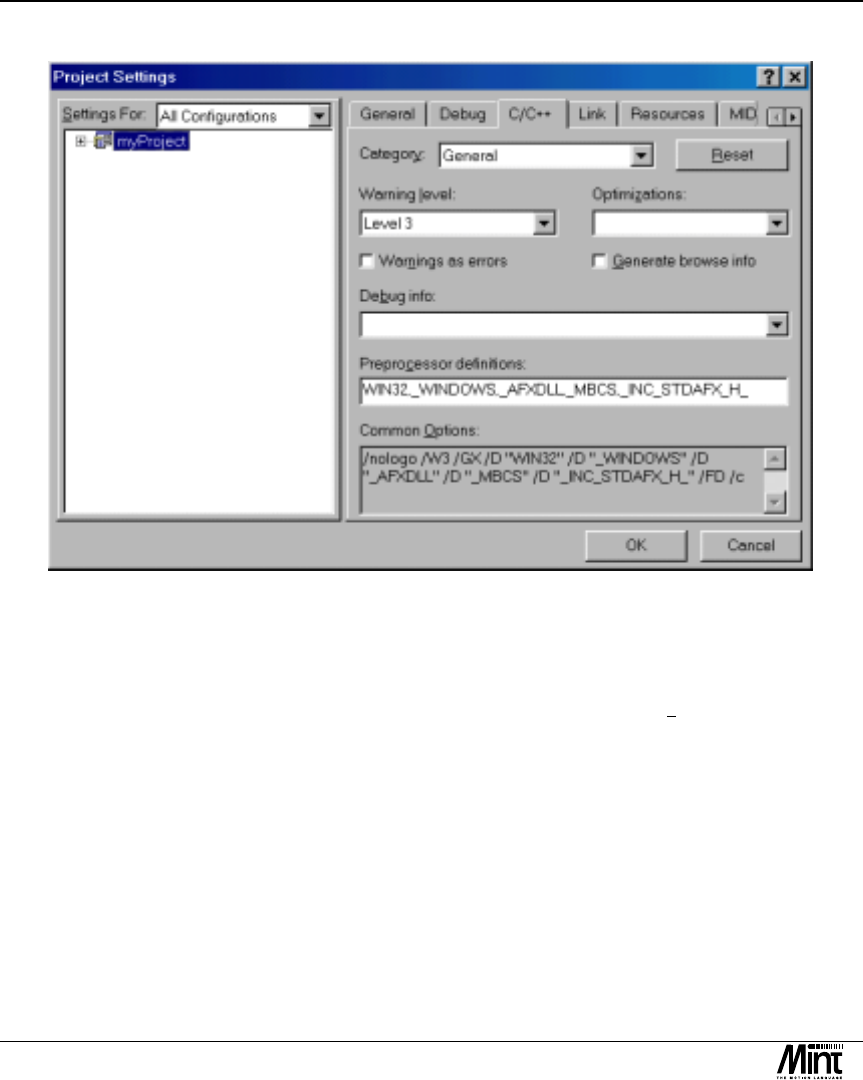
5. In the Project menu, select Settings. This will open the ‘Project Settings’ dialog. Select the C/C++ tab. In
the Category drop-down, select General. Select All Configurations in Settings For: on the left. In the
Preprocessor definitions: field, add _INC_STDAFX_H_ separating it from the preceding text with a comma.
This causes precomp.h to include the files previously included by stdafx.h. stdafx.h can still be edited to add
more files to the precompiled header as required. The dialog should now look similar to the screen shot
below. Press OK to store these changes. Now proceed to step 7.
Mint v4 PC Programming Guide
12 MN1278 05.2001
Figure 3-1: Visual C++ 6.0 Project Settings (step 5)
6. Add #include “precomp.h” to the top of each source (.c or .cpp) file. Note that no pre-compiler directives
(e.g. #include, #if, #define) should be placed above this line (although comments can be).
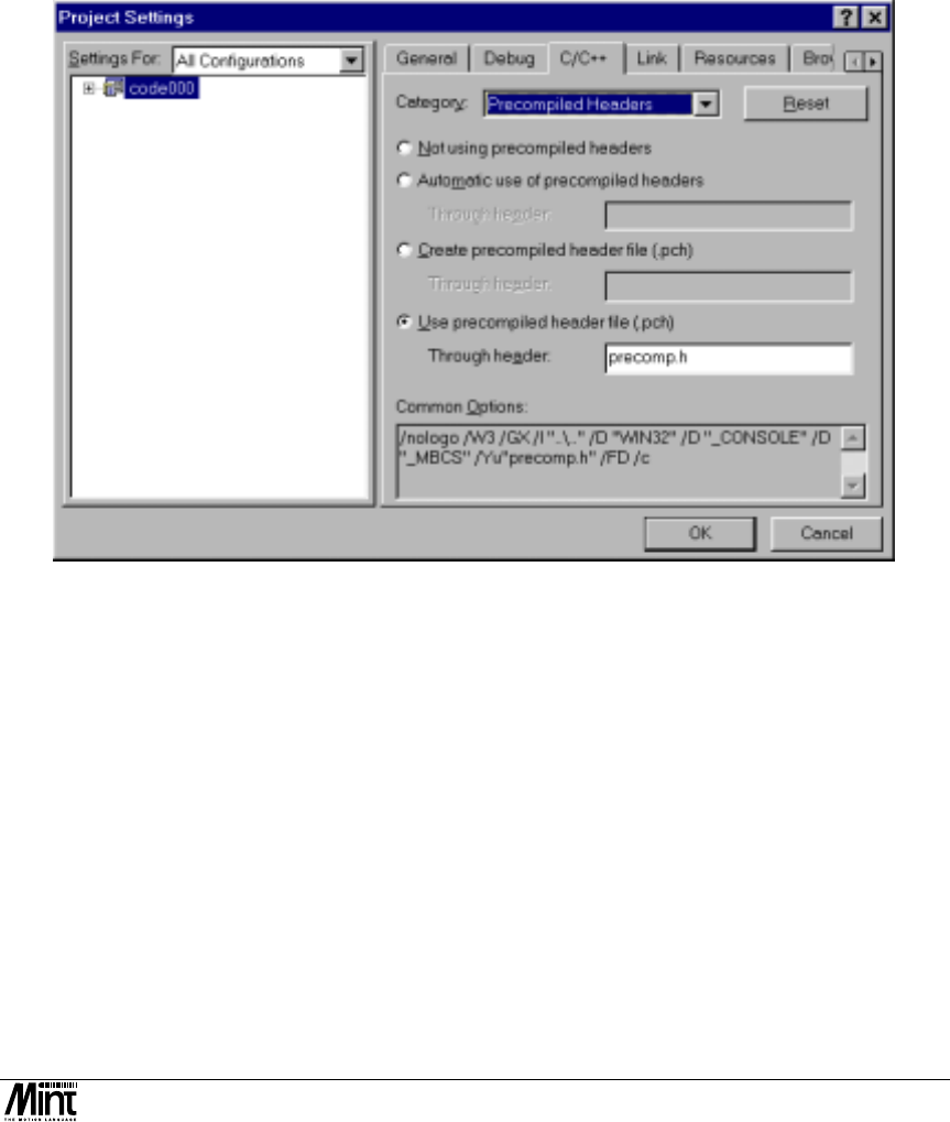
7. In the Project menu, select Settings. This will open the ‘Project Settings’ dialog. Select the C/C++ tab. In
the Category drop-down, select Precompiled Headers. Select All Configurations in Settings For: on the left.
Click on Use precompiled header file (.pch) and enter precomp.h in the Through Header text field. The
dialog should now look similar to the screen shot below. Press OK to store these changes. This will instruct
the project to use the pre-compiled file.
Using the Library with Various Languages
MN1278 05.2001 13
Figure 3-2: Visual C++ 6.0 Project Settings (step 7)
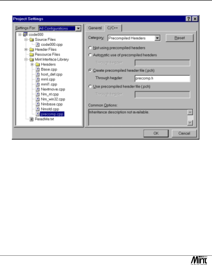
8. Select precomp.cpp in File View. Right click with the mouse and select Settings. This will open a dialog
similar to the dialog in step 3, but this time the dialog will only apply to precomp.cpp. Again, select Settings
For: All Configurations, and the Precompiled Headers Category on the C/C++ tab. This time, select Create
precompiled header file (.pch) and add precomp.h to the Through Header field. Check the dialog resembles
the one below and press OK.
Mint v4 PC Programming Guide
14 MN1278 05.2001
Figure 3-3: Visual C++ 6.0 Project Settings (step 8)
9. Rebuild the project. Precomp.cpp should now be the first file to build. This causes the pre-compiled header
file to be built. All the other files will now use this pre-compiled header as opposed to having to re-compile
all the header files each time.
3.1.3 A Visual C++ 6.0 Tutorial
This section will guide you through creating a Visual C application. The application will contain one button
which will toggle the state of the enable output for axis 0. Note that the axis must already be configured as servo
(use the Mint WorkBench to do this).

Using the Library with Various Languages
MN1278 05.2001 15
1. Open Visual C and select ‘ New’ from the ‘File’ menu. Select ‘MFC Appwizard(exe)’ from the ‘Projects’
tab. Enter the name ‘VCTutorial’ for the project and press ‘OK’.
Figure 3-4: Visual C++ 6 New Project (step 1)

Mint v4 PC Programming Guide
16 MN1278 05.2001
2. At Step 1 of the wizard, select ‘Dialog based’ and press ‘Finish’.
Figure 3-5: Visual C++ 6 Application Wizard (step 2)
3. Delete all the controls from the dialog (‘OK’ button, ‘Cancel’ button and ‘TODO: Place dialog controls
here.’ Text)

Using the Library with Various Languages
MN1278 05.2001 17
4. Select ‘Settings’ from the ‘Project’ menu. Select ‘All configurations’ from the ‘Settings For’ drop list.
Select the ‘C/C++’ tab and add _INC_STDAFX_H_ to the end of the ‘Preprocessor definitions’ list. This
will cause the existing “stdafx.h" to be included in the precompiled header.
Figure 3-6: Project Settings (step 4)

Mint v4 PC Programming Guide
18 MN1278 05.2001
5. Select ‘Precompiled Headers’ in the ‘Category’ drop list. Change ‘stdafx.h’ to ‘precomp.h’ in the ‘Use
Precompiled header’ option.
Figure 3-7: Project Settings (step 5)
Using the Library with Various Languages
MN1278 05.2001 19
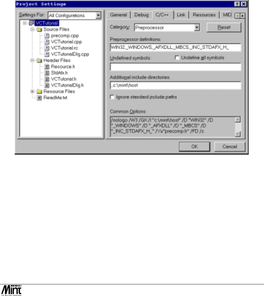
6. Select ‘Preprocessor’ from the ‘Category’ drop list. Add ‘.,’ (dot-comma ) followed by the path to the Mint
Interface Library header files in the ‘Additional include directories’ field. Press ‘OK’ to close the dialog.
Figure 3-8: Project Settings (step 6)
7. In the ‘FileView’ pane, delete stdafx.cpp. Right-click on ‘VCTutorialFiles’ and select ‘Add Files To
Project.’ Add ‘precomp.cpp’ (which should be in the c:\mint\host directory. )

Mint v4 PC Programming Guide
20 MN1278 05.2001
8. Right click on ‘precomp.cpp’ in ‘FileView’ and select ‘Settings’. Select ‘All Configurations’ in the ‘Settings
For’ drop list. Select ‘Precompiled headers’ in the category drop-list on the ‘C/C++’ tab. Click the ‘Create
Precompiled Header’ radio button and enter ‘precomp.h’ in the text field.
Figure 3-9: Project Settings (step 8)
9. Edit ‘VCTutorial.cpp’ and ‘VCTutorialDlg.cpp’. In both files, replace ‘#include “stdafx.h”’ with ‘#include
“precomp.h”’. Check the project builds !

Using the Library with Various Languages
MN1278 05.2001 21
10. Select ‘ClassView’. Right click on ‘CVCTutorialDlg’ and select ‘Add Member Function’. Copy the dialog
below.
Figure 3-10: Class View dialog (step 10)
Hit ‘OK’ to edit the new function. The MILError function will check the return code from all Mint Interface
Library functions. Edit the function as follows.
__int16 CVCTutorialDlg::MILError(__int16 nError)
{if ( erSUCCESS != nError ){
TCHAR szError[ szMAX_ERROR ];
getErrorString( szError, nError );
MessageBox( szError );
}
return nError;
}
11. At this point an attempt to build the code will fail at the link stage, as the source for getErrorString has not
been included. Add ‘host_def.cpp’ to the project and the code should build.

Mint v4 PC Programming Guide
22 MN1278 05.2001
12. Select ‘ClassView’. Right click on ‘CVCTutorialDlg’ and select ‘Add Member Variable’. Copy the dialog
below.
Figure 3-11: ClassView Dialog (step 12)
13. Find CVCTutorialDlg::OnInitDialog() in the file ‘VCTutorialDlg’. Replace the comment ‘// TODO: Add
extra initialization here’ with code to initialise the CController * object. This will depend on the controller
being used Note that m_pController could have been declared as the class that will be created (e.g.
CMintDrive) in which case <dynamic_cast> would not have to be used.. The #define values should be
modified to reflect the system being used.
MintDrive
#define NODE 10
#define COMMPORT 1
#define BAUDRATE 57600
m_pController = dynamic_cast<CController *> ( new CMintDrive ( NODE, COMMPORT, BAUDRATE,
TRUE ));
NextMove PC
#define NODE 0
#define ADDRESS 0x23C
m_pController = dynamic_cast<CController *> ( new CNextMovePC ( NODE, ADDRESS ));
NextMove PCI
#define NODE 0
#define CARDNUMBER 0
m_pController = dynamic_cast<CController *> ( new CNextMovePCI1 ( NODE, CARDNUMBER ));
NextMove BX
#define NODE 1
#define COMMPORT 2
#define BAUDRATE 9600
m_pController = dynamic_cast<CController *> ( new CNextMoveBX ( NODE, COMMPORT, BAUDRATE,
TRUE ));

Using the Library with Various Languages
MN1278 05.2001 23
14. The code should now compile, but not link. The following files should be added to the project to make it
link.
MintDrive & NextMove BX
base.cpp
baldorserial.cpp
host_def.cpp ( if you have not already added it )
logfile.cpp
mme.cpp
mml.cpp
serial.cpp
synchronisation.cpp
uncompress.cpp
NextMove PC
Base.cpp
Host_def.cpp ( if you have not already added it )
logfile.cpp
mml.cpp
nextmove.cpp
nm_nt.cpp
nm_win32.cpp
nmbase.cpp
nmstd.cpp
synchronisation.cpp
uncompress.cpp
NextMove PCI
Base.cpp
Host_def.cpp ( if you have not already added it )
logfile.cpp
mml.cpp
nm_pci1.cpp
nm_win32.cpp
nmbase.cpp
synchronisation.cpp
uncompress.cpp
15. Add a button to the dialog in the dialog editor. Double-click the button to edit the ‘OnButton1’ routine and
add this code.
void CVCTutorialDlg::OnButton1()
{BOOL b;
/*------------------------------------------------*/
/* Display a busy cursor. */
/*------------------------------------------------*/
CWaitCursor cur;
/*------------------------------------------------*/
/* Read the state of the axis 0 enable. */
/*------------------------------------------------*/
if ( erSUCCESS != MILError ( m_pController-> getDriveEnable( 0, &b )))
return;

Mint v4 PC Programming Guide
24 MN1278 05.2001
/*------------------------------------------------*/
/* Toggle it. */
/*------------------------------------------------*/
MILError ( m_pController->setDriveEnable( 0, ( FALSE == b )));
}
3.1.4 Compiling an ATL COM Project with Visual C.
When compiling an ATL COM project in Visual C, define _NO_AFX_. This prevents AFX and MFC files being
included.
3.1.5 RS485 Networks.
Individual controllers on an RS485 network can be accessed from within one application built using the source
code. One CController derived object can be created for each node on the network, and they will share the serial
port. Other applications will not be able to access controllers on the same port.
When using controllers on an RS485 link, remember to call setHandShakeMode(0) to disable hardware
handshaking. If there are several CController objects sharing the port, setHandShakeMode(0) only has to
be called for one of the controllers.
3.2 All Other Languages : The ActiveX Control ( OCX )
The ActiveX control is known as the Baldor Motion Library. When used, a TMintController object is created.
This can be used with a large number of languages. This section documents the use of the control with Visual
Basic 6 and Delphi 5, but the principle is the same in any language.
3.2.1 The ActiveX Control And The Languages It Can Be Used
With.
The control is a Active X (COM) control. It can be used with any languages that support
• Long integers (32 bit signed integers)
• Short integers ( 16 bit signed integers)
• Floats ( 32 bit floating point)
• BSTRs (Visual Basic Style strings)
• Pointers to all the above types.
Some languages do not support all of these data types (e.g. WonderWare InTouch does not support short integers
or pointers). For these languages, a ‘wrapper’ COM server may have to be written to convert to types used by the
language. Documentation should be provided with each language on how to perform this.

Using the Library with Various Languages
MN1278 05.2001 25
3.2.2 The ActiveX Control and Error Handling.
The ActiveX control produces COM (ActiveX) errors (exceptions) if any function fails. These will be trapped by
whatever exception handling method is implemented in that language (error handling in Visual Basic is
described in more detail in 3.3.1 ) The meaning of the error code can be found as follows:
• Mask off the top 16 bits ( or 17 in VB ) as the actual error code is only contained in the lower 16 bits.
• If the number is 200 hex ( 512 ) or greater it is a Mint Interface Library error.
• If the number is less than 200 hex ( 512 ) it is a standard COM error created by the framework, not the
Mint Interface Library.
3.2.3 The ActiveX Control and Serial Controllers.
One instance of (part of) the ActiveX control will be shared by all applications that use it. This means that more
than one application can access the same serial controller. This is not true of applications written with the C++
source code, where only one application can access a serial controller.
3.2.4 The ActiveX Control and RS485 Networks.
To access several nodes on an RS485 network, create one MintController object for each controller. The Visual
Basic RS485 example shows how Immediate commands can be performed and also how the command line of
each controller can be accessed.
When using controllers on an RS485 link, remember to call setHandShakeMode(0) to disable hardware
handshaking. If there are several MintController sharing the port, setHandShakeMode(0) only has to be
called for one.
3.2.5 Distributing an Executable Which Uses The ActiveX
Control.
When distributing a program which uses the ActiveX control, the files MILOCXZZZZ.OCX and
MILSERVERZZZZ.OCX (where ZZZZ is the version number) must be installed in the windows\system directory
and registered. Microsoft DCOM95 must also be installed. The easiest way to do this is to use a package such as
InstallShield Express and install MDAC2.0 which forces installation of DCOM95.
3.2.6 ‘Server Busy” / “Component Request Pending” Errors.

Mint v4 PC Programming Guide
26 MN1278 05.2001
When using the Active Control, warning messages such as the dialog above ( taken from a Visual Basic
application ) may be shown for slow operations such as file download. This is because the application expects
the ActiveX operation to finish its operation in a certain time ( the default for Visual Basic is five seconds. ) It
should be able to change these timeouts or remove the check completely, the method will be different for each
language. The following sections give advice on how to do this in Visual Basic and Visual C.
“Component Request Pending” in VB.
This error ( as shown in the dialog above ) can be prevented by adding the following code before the function
which times out is called.
App.OleRequestPendingTimeout = 60000
This will increase the timeout to a minute ( the timeout is in milliseconds. ) If this is still not long enough, the
value can be increased.
“Server Busy” in a Visual C MFC Application.
This is described fully in the Microsoft MSDN article Q248019 HOWTO: Prevent Server Busy Dialog Box From
Appearing During a Lengthy COM Operation.
To solve the problem add the following lines of code to the CWinapp derived classes InitInstance function.
AfxOleInit();

Using the Library with Various Languages
MN1278 05.2001 27
AfxOleGetMessageFilter()->EnableNotRespondingDialog( FALSE );
The file will have to include afxole.h
3.3 Visual Basic 6
3.3.1 Error number conversion
The error numbers returned in Err after a function call in Visual Basic differ from the constants defined in
mil.bas. To convert from an Err code (other than 0) to a MIL error, mask off the top 17 bits by ANDing with
&H7FFF and subtract &H200. There is a function called VBErrorToMIL in mil.bas to do this.
Public Function VBErrorToMIL(VBError&) As Long
If VBError& = 0 Then
VBErrorToMIL& = erSUCCESS
Else
VBErrorToMIL& = (VBError& And &H7FFF) - &H200
End If
End Function
If the result of this function is negative, the error was produced by VB, not the Mint Interface Library.
3.3.2 A Visual Basic Tutorial.
This section will guide you through creating a visual basic application. The application will contain one button
which will toggle the state of the enable output for axis 0. Note that the axis must already be configured as servo
(use the Mint WorkBench to do this).
1. Open Visual Basic and create a ‘New’ ‘Standard Exe.’
2. Select ‘Components’ from the ‘Project’ menu.

Mint v4 PC Programming Guide
28 MN1278 05.2001
Figure 3-12: Selection of Mint Component
3. Find ‘Baldor Motion Library XXXX for Mint Build XXXX in the list and check the box. In this example
the version 1107 is being used, but you this will have changed by the time this manual is printed. If there is a
choice of several versions, choose the most recent, unless you want to target an older version of Mint. Hit
‘OK’ This should have added the icon to the toolbox.
4. Select’Add Module’ from the ‘Project’ tab. Click on the ‘Existing’ tab and add ‘mil.bas’ which should be in
the ‘c:\mint\host’ directory.
5. Click on the icon in the toolbox and draw a square on the form. This will create a MintController
ActiveX control which will be used to communicate with the controller. Click on the control on the form
And change the name from MintController1 to myController.

Using the Library with Various Languages
MN1278 05.2001 29
6. In the Form_Load module we will tell the COM server which type of controller we want to communicate
with. These means the code will depend on the controller you have. The Consts should be editted to match
your system,
- MintDrive
Private Sub Form_Load()
Const NodeNumber = 10
Const CommPort = 1
Const Baudrate = 57600
myController.setMintDriveLink(NodeNumber, CommPort, Baudrate, True)
End Sub
- NextMove PC
Private Sub Form_Load()
Const NodeNumber = 0
Const Address = &H23C
myController.setNextMovePCLink(NodeNumber, Address)
End Sub
- NextMove PCI
Private Sub Form_Load()
Const NodeNumber = 0
Const CardNumber = 0
myController.setNextMovePCI1Link(NodeNumber, CardNumber)
End Sub
7. Add a command button, and place the following code behind it.
Private Sub Command1_Click()
Dim bState As Boolean
'*********************************************
' Read the state of the drive enable for axis 0
'*********************************************
myController.getDriveEnable 0, bState
'*********************************************
' Toggle the state of the enable
'*********************************************
myController.setDriveEnable 0, (bState = False)
End Sub
8. This code should now work. At this stage, an error handler will be added. Change the getDriveEnable code
to access an axis that does not exist. E.g.
myController.getDriveEnable -1, bState
This should create the following error when run.

Mint v4 PC Programming Guide
30 MN1278 05.2001
Figure 3-13: Example Dialog Box
9. Add the following code to trap this (or any other error).
Private Sub Command1_Click()
Dim bState As Boolean
On Error GoTo command1_error
'*********************************************
' Read the state of the drive enable for axis 0
'*********************************************
myController.getDriveEnable -1, bState
'*********************************************
' Toggle the state of the enable
'*********************************************
myController.setDriveEnable 0, (bState = False)
Exit Sub
command1_error:
'*********************************************
' Display the error and leave subroutine
'*********************************************
MsgBox Error$
Exit Sub
End Sub

Using the Library with Various Languages
MN1278 05.2001 31
3.4 Borland Delphi 5.0
NOTE: Before any programs, including the examples, can be built, the type library must be imported. See
step 2.
This section will guide you through creating a simple Delphi application. The application will contain one button
which will toggle the state of the drive enable output for axis 0. Note that the axis must already be configured as
servo (use the Mint WorkBench to do this).
1. Open Delphi and create a new project.
2. If this is the first time a Delphi Mint Interface Library application has been created on this machine a type
library file will have to be created. Select ‘Import ActiveX Control’ from the ‘Components’ menu. Find
‘Baldor Motion Control Library XXXX for Mint XXXX in the list and check the box. In this example the
version 1109 is being used, but this will have changed by the time this manual is printed. If there is a choice
of several versions, choose the most recent, unless you want to target an older version of Mint. Hit
‘Install…’ and follow the default options.

Mint v4 PC Programming Guide
32 MN1278 05.2001
Figure 3-14: Delphi – Installing Mint Component
3. Select the ActiveX tab on the toolbar. The rightmost icon should now be the MintController icon.
Click the icon and then click Form1 to create an instance of the control. Examining the properties of the
control should show that the name is MintController1.
4. We now have to edit the FormCreate function. Double click on Form1 to open the FormCreate function.
The line of code depends on the controller being used. It will tell the COM server which type of controller
we want to communicate with. These means the code will depend on the controller you have. The consts
should be editted to match your system,

Using the Library with Various Languages
MN1278 05.2001 33
- MintDrive
procedure TForm1.FormCreate(Sender: TObject);
const NodeNumber = 10;
const CommPort = 1;
const BaudRate = 57600;
begin
MintController1.setMintDriveLink( NodeNumber, CommPort, BaudRate, TRUE );
end;
- NextMove PC
procedure TForm1.FormCreate(Sender: TObject);
const NodeNumber = 0;
const Address = $23c;
begin
MintController1.setNextMovePCLink( NodeNumber, Address );
end;
- NextMove PCI
procedure TForm1.FormCreate(Sender: TObject);
const NodeNumber = 0;
const CardNumber = 0;
begin
MintController1.setNextMovePCI1Link( NodeNumber, CardNumber );
end;
end.
5. Add a button and double click on it to edit the Button1Click procedure. Add the following code.
procedure TForm1.Button1Click(Sender: TObject);
var wbEnabled : WordBool;
begin
{ Read the current state of the drive enable. }
MintController1.getDriveEnable( 0, wbEnabled );
{ Write back the toggled value. }
MintController1.setDriveEnable( 0, ( wbEnabled = FALSE ));
end;
end.

Mint v4 PC Programming Guide
34 MN1278 05.2001
6. This code should now run. To add an error handler, change the first parameter to setDriveEnable to –1 to
create a run time error. This will raise an EOleException error. To trap this error, modify the code as
follows.
procedure TForm1.Button1Click(Sender: TObject);
var wbEnabled : WordBool;
begin
{ Trap errors. All errors will cause program flow to jump to the except }
try
{ Read the current state of the drive enable. }
MintController1.getDriveEnable( 0, wbEnabled );
{ Write back the toggled value. }
MintController1.setDriveEnable( 0, ( wbEnabled = FALSE ));
except
{ This is called on any function in the try block failing }
On E: Exception do MessageBox ( 0, pchar(E.Message), 'Mint Interface Library Call
failed', 0 );
end;
end;
To prevent Delphi from halting program execution in the event of an exception the ‘Stop on Delphi Exceptions’
check box must be cleared. This is found in the ‘Debugger Options’ from the ‘Tools’ menu.
Figure 3-15: Delphi - Debugger Options

PC Based Motion Control
MN1278 05.2001 35
4. PC Based Motion Control
4
This chapter covers creating motion applications on the host PC.

Mint v4 PC Programming Guide
36 MN1278 05.2001
The Mint Interface Library provides all of the functionality that is available in the Mint programming language.
Motion applications can be written on the host PC by calling functions from the Mint Interface Library. When a
function is called, the Mint Interface Library communicates with the controller and calls the specified function
directly on the controller. The Mint functionality is still being performed by the controller but it has been
initiated directly by a host application. The real-time elements of Mint are still run on the controller but the
sequencing can be controlled by the host application.
The following diagram shows the architecture, known as Immediate Command Mode:
Controller
Mint Host I/F
Terminal/
Comms
MINT Motion Library
Servo
Loop
Profiler x N
x N
ICM
Device
Driver
Host
MIL
Figure 4-1: Immediate Command Mode Interface
Immediate Command Mode (ICM) is the method that allows Mint motion functions to be called from a host
application, bypassing Mint.
Calling functions from the host is particularly useful if there is a large amount of processing to do (i.e. calculation
of multi-axis paths) as the host can do the processing and send the commands to the controller. Note that these
functions can be used in conjunction with a Mint program. For example a Mint program handles the I/O and the
host calculates the path and sends it to the controller using setVectorA().
The Immediate Command Mode interface can also be used for testing applications to be compiled by a C31
compiler and run on NextMove. This is described in Mint v4 Embedded Programming Guide.
There is a one to one correlation between Mint commands and Mint Interface Library Functions. For example,
within a Mint program, the MOVER keyword is used to create a relative positional move on an axis.
MOVER.0 = 10
The Mint Interface Library function for this is setMoveR.
setMoveR (0, 10)
The keyword has been prefixed with set. Almost all Mint keywords are available in the Mint Interface Library.
The will be prefixed with set for writes, get for reads and do for commands.

PC Based Motion Control
MN1278 05.2001 37
Functions called from the host fall into two categories. Those functions that replicate Mint keywords are known
as Mint Motion Library calls (MML) and those functions which are general communications functions are known
as Mint Interface Library calls (MIL).
Example:
The following code is a Visual Basic extract showing a host application set up a move on a NextMove BX. The
TMintController object has been added to the form and named ‘myController’.
‘ Set up some data
Dim axis0(1) As Integer
Dim isIdle As Boolean
axis0 = 0
' Create handle to NextMove: node, comm port, baud rate, open
myController.setNextMoveBXLink 2, 1, 19200, 1
‘ Set move parameters on axis 0
myController.setSpeed 0, 40!
myController.setAccel 0, 400!
myController.setDecel 0, 400!
myController.doReset 0
‘ Load the move and start it
myController.setMoveR 0, 100
myController.doGo 1, axis0
‘ Wait until move is completed
DomyController.getIdle 0, isIdle
Loop Until isIdle
4.1 Limitations of PC based applications
There are a number of event handlers available in Mint such as #ONERROR. Only NextMove PCI supports
events to the host. This means that event handlers can be installed in the host application that are called directly
when a Mint event occurs. For other controllers, the event handlers must be placed in a Mint program.
Commands called from the host execute slower than if called directly on the controller. See Appendix 2 for
example timings.
The host functions take priority over the Mint program running on the controller. If MML functions are called
continuously from the host, this will slow the execution speed of the Mint program.

Mint v4 PC Programming Guide
38 MN1278 05.2001
4.2 Events and Interrupt Control on NextMove PCI
The NextMove PCI controller requires a device driver to be installed on the host PC in order for communication
to be established between it and the controller. The use of device drivers makes it possible for interrupts from the
card to be trapped and handled. The Dual Port RAM interface allows the PC to interrupt the controller and the
controller to interrupts the host. Interrupt handling using the NextMove PCI controller is supported under both
Windows NT and Windows 95 and 98.
4.2.1 Writing and Installing an Interrupt Handler
When the controller interrupts the host PC the device driver will trap the interrupt and determine what ‘type’ of
event has occurred. Following this it will call the appropriate event handler.
NextMove can generate a number of events in response to certain situations:
• Axis idle - an axis has become idle.
• CAN 1 (CAN Open) – an event on CAN bus 1
• CAN 2 (Baldor CAN) – an event on CAN bus 2
• Comms – the comms location 1 to 5 has been written to
• DPR event – the user generated a DPR event ( see 4.2.3 Interrupting the Host from a Mint Program (
DPR Events ))
• Errors – an error occurred on the NextMove card
• Fast position latch – an axis has latched position
• Digital input active – a digital input has become active
• Move buffer low - the numbers of moves in a move buffer drops below a specified threshold.
• Reset – the NextMove PCI card has reset
• Serial receive – the controller has put a character into its pseudo serial transmit buffer.
• Stop switch – a stop switch has become active
• Timer – the timer event period has expired
The events are prioritised in the following order:
Priority Event
0: Highest Serial Receive
1 Error
2 CAN 1 (CANOpen)
3 CAN 2 (Baldor CAN)
4 Stop switch
5 Fast position latch

PC Based Motion Control
MN1278 05.2001 39
Priority Event
6 Timer
7 Digital input
8 Comms
9 DPR event
10 Move Buffer Low
11 Axis Idle
Note: The reset event is generated if the controller resets, hence this is not generated by the firmware and
is consequently not subject to the priority scheme.
The NextMove PCI controller will check for a pending event every 2ms. If multiple events occur within a 2ms
tick, then the above priority system will be used to decide which event to generate. A higher priority event will
interrupt a lower priority event. Each event is processed within a separate thread by the host PC application. If
more than one event is active on the host PC they will execute concurrently.
In order for an event to be generated the, the appropriate event handler must be installed.
The event handlers are installed with the following functions in C++:
Axis Idle
The install function for axis idle events, it accepts a pointer to a function, if this is a NULL pointer the handler is
uninstalled.
typedef void TAxisIdleEventHandler (void *pController, __int16 nAxisBitPattern)
__int16 installAxisIdleEventHandler (TAxisIdleEventHandler *pHandler)
CAN1
The install function for CAN events on bus 1, it accepts a pointer to a function, if this is a NULL pointer the
handler is uninstalled.
typedef void TCANEventHandler (void *pController)
__int16 installCAN1EventHandler (TCANEventHandler *pHandler)
CAN2
The install function for CAN events on bus 2, it accepts a pointer to a function, if this is a NULL pointer the
handler is uninstalled.
typedef void TCANEventHandler (void *pController)
__int16 installCAN2EventHandler (TCANEventHandler *pHandler)
Comms
The install function for Comms events, it accepts a pointer to a function, if this is a NULL pointer the handler is
uninstalled.
typedef void TCommsEventHandler (void *pController, __int32 lCommsEventPending)
__int16 installCommsEventHandler (TCommsEventHandler *pHandler)

Mint v4 PC Programming Guide
40 MN1278 05.2001
DPR
The install function for DPR events, it accepts a pointer to a function, if this is a NULL pointer the handler is
uninstalled.
typedef void TDPREventHandler (void *pController, __int16 nCode)
__int16 installDPREventHandler (TDPREventHandler *pHandler)
Errors
The install function for error events, it accepts a pointer to a function, if this is a NULL pointer the handler is
uninstalled.
typedef void TErrorEventHandler (void *pController)
__int16 installErrorEventHandler (TErrorEventHandler *pHandler)
Fast Position Latch
The install function for fast position latch events, it accepts a pointer to a function, if this is a NULL pointer the
handler is uninstalled.
typedef void TFastInEventHandler (void *pController)
__int16 installFastInEventHandler (TFastInEventHandler *pHandler)
Digital Input
The install function for digital input events, it accepts a pointer to a function, if this is a NULL pointer the
handler is uninstalled.
typedef void TInputEventHandler (void *pController,
__int16 nBank, __int32 lActivatedInputs)
__int16 installInputEventHandler (TInputEventHandler *pHandler)
Move Buffer Low
The install function for move-buffer-low events, it accepts a pointer to a function, if this is a NULL pointer the
handler is uninstalled.
typedef void TMoveBufferLowEventHandler (void *pController, __int16 nAxisBitPattern)
__int16 installMoveBufferLowEventHandler (TMoveBufferLowEventHandler *pHandler)
Reset
The install function for reset events, it accepts a pointer to a function, if this is a NULL pointer the handler is
uninstalled.
typedef void TResetEventHandler (void *pController, __int16 nCode)
__int16 installResetEventHandler (TResetEventHandler *pHandler)
Serial Recieve
The install function for serial receive events, it accepts a pointer to a function, if this is a NULL pointer the
handler is uninstalled.
typedef void TSerialReceiveEventHandler (void *pController)
__int16 installSerialReceiveEventHandler (TSerialReceiveEventHandler *pHandler)

PC Based Motion Control
MN1278 05.2001 41
Stop Switch
The install function for stop switch events, it accepts a pointer to a function, if this is a NULL pointer the handler
is uninstalled.
typedef void TStopSwitchEventHandler (void *pController)
__int16 installStopSwitchEventHandler (TStopSwitchEventHandler *pHandler)
Timer
The install function for timer events, it accepts a pointer to a function, if this is a NULL pointer the handler is
uninstalled. The parameter passed to the event handler is always zero.
typedef void TTimerEventHandler (void *pController, __int16 nTimerEvent)
__int16 installTimerEventHandler (TTimerEventHandler *pHandler)
Unknown
The install function for unknown events, it accepts a pointer to a function, if this is a NULL pointer the handler is
uninstalled.
typedef void TUnknownEventHandler (void *pController, __int16 nCode)
__int16 installUnknownEventHandler (TUnknownEventHandler *pHandler)
This handler will pick up any otherwise un-handled interrupt codes on the host. Under normal circumstances it
will not be called, as all interrupts will be routed to the appropriate event hander. If this handler is not installed
then unknown interrupts will be discarded.
Example:
The following code sample will install a timer event handler.
// prototypes
void cdecl FAR myTimerEventHandler (void *p, __int16 nTimerEventNumber);
// main program
void main ( void )
{// Create an instance of the CNextMovePCI class
CNextMovePCI1 myPCI ( 0, 0 );
// install timer event handler
myPCI.installTimerEventHandler ( myTimerEventHandler ));
myPCI.setTimerEvent(1000); // set periodic timer event to 1000ms
while(1) {
myPCI.setRelay(0, 1); // Turn the main board relay on
myPCI.doWait(500); // Wait for 500 ms
myPCI.setRelay(0, 0); // Turn the main board relay off
myPCI.doWait(500); // Wait for 500 ms
}
}

Mint v4 PC Programming Guide
42 MN1278 05.2001
// timer event handler
void myTimerEventHandler ( void *p, __int16 nTimerEventNumber )
{cout << "Timer Event” << endl;
}
When a host PC event handler is called, the embedded application running on the controller will continue to
execute.
4.2.2 Event Control Functions
There are various functions that can be used to control events generation. These are detailed below
The user can read which events are currently active using the function:
getEventActive
Any currently pending events can be cleared selectively using the function:
setEventPending
This accepts the same bit pattern as above, clearing a set bit will clear the pending flag for that event. Hence
passing a value of zero will clear all pending interrupts.
Once a handler has been installed the event generation can be disabled by using the function:
setEventDisable
This function accepts a bit pattern as above. Setting a bit will disable the generation of that type of event. Hence
setting this to zero will enable all events which have a handler installed.
The function:
getEventDisable
Will return a bit pattern of any currently disabled interrupts.
By default all digital inputs will generate events when they become active. These digital inputs can be masked so
that they do not generate events using the function:
setIMask
This function accepts a bit pattern which represents all digital inputs, it the bit is set then the digital input will
generate an event when the input becomes active.
Then function:
getIMask
Will return a bit pattern representing those digital inputs which will generate an event when they become active.

PC Based Motion Control
MN1278 05.2001 43
4.2.3 Interrupting the Host from a Mint Program ( DPR Events )
Events can be manually generated in both directions using the function doDPREvent and the DPREvent handler.
If the host PC calls doDPREvent, this will generate an interrupt to the controller that will call the DPREvent
handler on the controller.
If the controller calls the function doDPREvent, this will generate an interrupt to the host PC that will call the
DPREvent handler on the host PC.
The function doDPREvent accepts an 8 bit code which is passed to the event handler.
Example:
The below code sample will install a DPREvent handler on the host, when a DPREvent is received the code is
printed.
// prototypes
void myDPREventHandler (void *p, __int16 nCode);
// main program
void main(void)
{// Create an instance of the CNextMovePCI class
CNextMovePCI1 myPCI(0, 0);
// install timer event handler
myPCI.installDPREventHandler ( myDPREventHandler ));
}
// DPREvent handler
void myDPREventHandler (void *p, __int16 nCode)
{cout<<"DPREvent”<<nCode<<endl;
}
When this application is running on the host PC, calling DPREVENT from either Mint or an embedded
application will generate an interrupt to the PC calling the DPREvent handler.
4.2.4 Handling Events Using the ActiveX Control
As the ActiveX control supports all events; hence, any application that can use the ActiveX control can trap and
handle events from the controller. This allows event handling using Visual Basic and Delphi.
Once the ActiveX Control has been included in the project, the event handlers are accessed as ActiveX events.
The functions listed below are used to tell the controller that a handler exists on the host PC and events of this
type should be generated.
installAxisIdleEventHandler
installCAN1EventHandler
installCAN2EventHandler
installCommsEventHandler
installDPREventHandler

Mint v4 PC Programming Guide
44 MN1278 05.2001
installErrorEventHandler
installFastInEventHandler
installInputEventHandler
installMoveBufferLowEventHandler
installSerialReceiveEventHandler
installStopSwitchEventHandler
installResetEventHandler
installTimerEventHandler
installUnknownEventHandler
The passed parameter is a BOOLEAN parameter.
• TRUE indicates that a handler exists on the host PC
• FALSE indicates that a handler does not exist on the host PC.
VisualBasic Example:
Create a MintController object called ‘nmPCI’.
in the Form_Load function add:
nmPCI.setNextMovePCI1Link 0, 0
nmPCI.installTimerEventHandler TRUE
nmPCI.setTimerEvent 1000
Double click on the MintController object and select the TimerEventHandler function, add the code:
Dim b As Boolean
nmPCI.getRelay 0, b
IfbThen
nmPCI.setRelay 0, 0
Else
nmPCI.setRelay 0, 1
End If
When the timer event is generated on the controller, this will interrupt the host PC and create a timer event. This
is trapped by the ActiveX control and executes the code in the timer event.
In this example the timer event is set to trigger every second, the code within the timer event handler will toggle
the state of the relay.

NextMove PCI and Non-Micorsoft Operating Systems
MN1278 05.2001 45
5. NextMove PCI and Non-Microsoft Operating
Systems
5
This chapter details how to use the NextMove PCI with operating systems
other than Windows NT and Windows 9x.

Mint v4 PC Programming Guide
46 MN1278 05.2001
This Chapter covers implementing an interface to NextMove PCI in under an operating system other than the
systems supported by the standard Baldor Motion Toolkit for example QNX, Linux etc.
A special version of the CNextMovePCI1 class has been written. This class (called CSimplePCI) provides all the
functions required except the actual hardware interface functions, which must be provided by the user.
5.1 How to Recognize the NextMove PCI.
To find the NextMove PCI, the computer’s PCI controller must be interrogated. The method for this will differ
between operating systems. Each PCI device can be recognized by its Vendor ID and Device ID. For a
NextMove PCI the following applies:
Vendor ID = 145F(Hex)
Device ID = 0001.
5.2 Host Accessible Hardware on NextMove PCI.
The are three blocks of hardware which can be accessed on NextMove PCI. One of these is mapped into both
memory and IO space, so it appears as if there are four blocks which can be accessed.
Block Size Map type Description
1 128 bytes Memory This is NextMove’s PCI chip (also referred to as the PLX chip.) It
controls the hardware reset and interrupt lines.
2 128 bytes I/O This is also the PCI controller chip, but mapped into IO space, not
memory.
3 16K Memory This is the Dual Port RAM.
4 32 bytes I/O This is currently unused.
Of these, the two memory mapped areas ( blocks 1 and 3 ) will be used. Blocks 2 and 4 are can be ignored. The
memory mapped addresses of blocks 1 and 3 should be read from the computers PCI controller. The memory
address of Block 1 must be stored for the functions PLXRead and PLXWrite and the address Block 3 is mapped
into must be stored for use with the functions getLong and setLongInternal.
5.3 The CSimplePCI class.
The CSimplePCI class splits the hardware access functions from the rest of the Mint Interface Library. To use
the class inherit from the CSimplePCI class and supply the virtual functions required (listed below). The easiest
way to do this is to modify the CMySimplePCI example.

NextMove PCI and Non-Micorsoft Operating Systems
MN1278 05.2001 47
5.3.1 The CMySimplePCI Example.
The CMySimplePCI example overloads CSimplePCI to create a class which can be used to communicate with
NextMove PCI under Windows 9X and Windows NT using the CSimplePCI interface. It is laid out in such a
way that the Windows specific code can easily be replaced with code specific to another operating system.
5.3.2 Functions Required by the Overloaded Class.
The CMySimplePCI class declaration is as follows. It shows all the functions required.
#include "simplepci.h"
class CMySimplePCI : public CSimplePCI{
public:
/*------------------------------------------------------------------*/
/* START : These functions MUST be defined. */
/*------------------------------------------------------------------*/
CMySimplePCI ( int nNode, int nCard );
__int16 doDeviceClose ( void );
__int16 getDeviceOpen ( BOOL *bOpen );
__int16 doDeviceOpen ( void );
__int16 getLong ( __int16 nAddress, __int32 FAR *lplValue );
protected:
__int16 InternalSetLong ( __int16 nAddress, __int32 lLong );
__int16 PLXRead ( __int16 nRegister, __int32 *plValue );
__int16 PLXWrite ( __int16 nRegister, __int32 lValue );
/*------------------------------------------------------------------*/
/* END : These functions MUST be defined. */
/*------------------------------------------------------------------*/
/*------------------------------------------------------------------*/
/* START : Replace this. */
/*------------------------------------------------------------------*/
protected:
bool m_bWinNT; // true : WinNT, false Win9X
HANDLE m_hndFile; // Handle to the device driver.
/*------------------------------------------------------------------*/
/* END : Replace this. */
/*------------------------------------------------------------------*/
};
The header shows how the code in the CMySimplePCI example is laid out. There are blocks marked with
/*================================================================*/
/* START : Replace this */
/*================================================================*/

Mint v4 PC Programming Guide
48 MN1278 05.2001
…
…
/*================================================================*/
/* END : Replace this */
/*================================================================*/
which show code that is only relevant to the example. This is code that should be replaced with code specific to
that operating system.
Only code in the files MySimplePCI.h and MySimplePCI.cpp should be modified. Do NOT modify
SimplePCI.h and SimplePCI.cpp
Constructor.
A constructor must be supplied. This constructor must call the CSimplePCI constructor, passing the node and
card number. Any other parameters required by the class may be passed. The CMySimplePCI constructor is as
follows
/*--------------------------------------------------------------------*/
/* CMySimplePCI */
/* */
/* Function: Constructor */
/* */
/* Argument list: */
/* int nNode - Node number : not currently used */
/* int nCard - PCI card number */
/* Return value: */
/* */
/*--------------------------------------------------------------------*/
CMySimplePCI::CMySimplePCI( int nNode, int nCard ) : CSimplePCI ( nNode, nCard )
{/*==================================================================*/
/* START : Replace this */
====================================================================*/
m_hndFile = INVALID_HANDLE_VALUE;
/*------------------------------------------------------------------*/
/* Find if we are running under Win9X or WinNT. */
/*------------------------------------------------------------------*/
OSVERSIONINFO VersionInfo;
VersionInfo.dwOSVersionInfoSize = sizeof ( OSVERSIONINFO );
GetVersionEx ( &VersionInfo );
m_bWinNT = ( 0 != ( VersionInfo.dwPlatformId & VER_PLATFORM_WIN32_NT ));
/*==================================================================*/
/* END : Replace this */
====================================================================*/
doDeviceOpen ();
}
The constructor should initialize any required data and then call doDeviceOpen() to allow communications with
the controller to start.

NextMove PCI and Non-Micorsoft Operating Systems
MN1278 05.2001 49
doDeviceClose
This function releases any resources which had been taken by the class.
getDeviceOpen
This function must report whether the class has control of any resources it requires to communicate with the
controller and whether that controller is physically present. In the MySimplePCI example this reports whether it
can communicate with device driver. In Windows 95 on instance of the device driver is created in memory per
device it finds, so if the device driver instance exists in memory, the NextMove PCI is present. Under Windows
NT, there is one device driver to handle all NextMoves, so the device driver must be interrogated to find if that
card number is present.
doDeviceOpen
This function must take any resources required to communicate with the controller. In the MySimplePCI
example, this creates a handle to the device driver.
getLong
This function must read from DPR (block 3 in section 5.2 ) This may take the form of (as in the MySimplePCI
example) instructing the device driver to perform the task. The read should be a simple 32 bit read from the
memory address the DPR has been mapped into (Block 3).
internalSetLong
This function must write to DPR (block 3 in section 5.2). This may take the form of (as in the MyMySimplePCI
example) instructing the device driver to perform the task. The write should be a simple 32 bit write to the
memory address the DPR has been mapped into (Block 3).
PLXRead
This function must read from the PLX chip (Block 3 in section 5.2) This may take the form of (as in the
MySimplePCI example) instructing the device driver to perform the task. The read should be a simple 32 bit
read from the memory address the PLX chip has been mapped into (Block 1).
PLXWrite
This function must write to the PLX chip (Block 3 in section 5.2 ) This may take the form of (as in the
MySimplePCI example) instructing the device driver to perform the task. The write should be a simple 32 bit
write to the memory address the PLX chip has been mapped into (Block 1).
5.3.3 Files to Include in a CSimplePCI Derived Class Project.
The following Mint Interface Library files must be included in the project:
• base.cpp
• mml.cpp
• nmbase.cpp
• simplepci.cpp

Mint v4 PC Programming Guide
50 MN1278 05.2001
The following files may also be added:
• host_def.cpp : if the function getErrorString is being used.
• precomp.cpp : if this file is being used to construct the precompiled header.

Appendix 1: DPR Map
MN1278 05.2001 51
6. Appendix 1: DPR Map
Each area of the address map is described below. Where an address is shown, that is the DPR location. Where
an address offset is shown, that offset is added to the base address. Floating point numbers will conform to C31
format. It is up to the PC interface to convert to IEEE format before passing the data to the PC application.
Likewise, IEEE floating point numbers must be converted to C31 format before writing to the DPR. All library
functions do this automatically.
• The update time on NextMove is 2ms.
• Where units are shown, the key is as follows:
uu - user units
uu/s - user units / second
au - analogue units. (See ADCMode keyword for explanation of ranges)
% - percentage
cts - encoder counts
• All addresses and address offsets are in hex.
6.1 NextMove PCI DPR Map
Dual Port RAM on NextMove PCI has 4K of 32 bit data. The DPR map is similar to NextMove PC but certain
areas are designated as read only. This means that if the user tries to write to these locations, the data may be
corrupted.
The Dual Port RAM on NextMove PCI is 32 bit rather than the 16 bit wide DPR on NextMove PC, hence 32 bit
values on will use two 16 bit DPR locations. In order for the memory map of DPR to be consistent between the
two controllers where 32 bit values are stored, NextMove PCI will have a redundant location.
Address Use Read Only
0xFFF 0xFFF Interrupt Host
0xFFE Interrupt NextMove
0xFFD
Control Registers Reserved
0xFE0 0xFE0
0xFDF 0xFDF
1K User Area
0xBE0 0xBE0
0xBDF
Reserved for future use

Mint v4 PC Programming Guide
52 MN1278 05.2001
Address Use Read Only
0x600
0x5FF 0x5FF
ICM expansion
0x500 0x500
0x4FF 0x4FF
Reserved for future axes
0x480 0x480
0x47F
Axis 11 Data
0x460
0x45F
Axis 10 Data
0x440
0x43F
Axis 9 Data
0x420
0x41F
Axis Data Axis 8 Data
0x400 0x400
0x3FF 0x3FF Reserved
0x3FE Reserved
0x3FD Scratchpad (Unused)
Control Registers 0x3FC Functionality Code
0x3FB 0x3FB Application Code
0x3FA 0x3FA Interrupt Data
0x3F9 0x3F9 Interrupt Data
0x3F8 0x3F8 ICM handshake
0x3F7 0x3F7
Reserved (Old user area)
0x29C 0x29C
0x29B 0x29B
Comms (99 locations)
0x1D6 0x1D6
0x1D5 0x1D5
Serial Transmit Buffer
0x193
0x192
Pseudo Serial Serial Receive Buffer
0x150 0x150
0x14F 0x14F
Immediate Command Mode

Appendix 1: DPR Map
MN1278 05.2001 53
Address Use Read Only
0x130 0x130
0x12F 0x12F
IO Data
0x110 0x110
0x10F 0x10F
Axis 7 Data
0x0F0
0x0EF
Axis 6 Data
0x0D0
0x0CF
Axis 5 Data
0x0B0
0x0AF
Axis 4 Data
0x090
0x08F
Axis 3 Data
0x070
0x06F
Axis 2 Data
0x050
0x04F
Axis 1 Data
0x030
0x02F
Axis Data Axis 0 Data
0x010 0x010
0x00F 0x00F Reserved
0x00E
0x00D 1ms Timer Tick
0x00C Axis Configurations (8-11)
0x00B Axis Configurations (0-7)
0x00A MINT Error Line
0x009 MINT Error
0x008 MINT Status
0x007 MINT Line Number
0x006 2ms Timer Tick
0x005 Build ID
0x004 Analog I/O Mix
Status/Control Registers 0x003 Digital I/O Mix

Mint v4 PC Programming Guide
54 MN1278 05.2001
Address Use Read Only
0x002 Axis Mix
0x001 DPR Status Register
0x000 0x000 DPR Control Register
6.2 NextMove PC DPR Map
Dual Port RAM on NextMove PC has 1K of 16 bit data.
Address Use Read Only
0x3FF 0x3FF Interrupt Host
0x3FE Interrupt NextMove
0x3FD Scratchpad (Unused)
Control Registers 0x3FC Functionality Code
0x3FB 0x3FB Application Code
0x3FA 0x3FA Interrupt Data
0x3F9 0x3F9 Interrupt Data
0x3F8 0x3F8 ICM handshake
0x3F7 0x3F7
Reserved (Old user area)
0x29C 0x29C
0x29B 0x29B
Comms (99 locations)
0x1D6 0x1D6
0x1D5 0x1D5
Serial Transmit Buffer
0x193
0x192
Pseudo Serial Serial Receive Buffer
0x150 0x150
0x14F 0x14F
Immediate Command Mode
0x130 0x130
0x12F 0x12F
IO Data
0x110 0x110
0x10F 0x10F
Axis 7 Data
0x0F0
0x0EF
Axis 6 Data
0x0D0

Appendix 1: DPR Map
MN1278 05.2001 55
Address Use Read Only
0x0CF
Axis 5 Data
0x0B0
0x0AF
Axis 4 Data
0x090
0x08F
Axis 3 Data
0x070
0x06F
Axis 2 Data
0x050
0x04F
Axis 1 Data
0x030
0x02F
Axis Data Axis 0 Data
0x010 0x010
0x00F 0x00F Reserved
0x00E
0x00D 1ms Timer Tick
0x00C Axis Configurations (4-7)
0x00B Axis Configurations (0-3)
0x00A MINT Error Line
0x009 MINT Error
0x008 MINT Status
0x007 MINT Line Number
0x006 2ms Timer Tick
0x005 Build ID
0x004 Analog I/O Mix
Status/Control Registers 0x003 Digital I/O Mix
0x002 Axis Mix
0x001 DPR Status Register
0x000 0x000 DPR Control Register

Mint v4 PC Programming Guide
56 MN1278 05.2001
6.3 Status and Control Registers
Address Use Symbolic Constant Read Only
0x000 DPR Control Register roCONTROL
0x001 DPR Status Register roSTATUS
0x002 Axis Mix roAXIS_MIX
0x003 Digital I/O Mix roNUM_DIO
0x004 Analog I/O Mix roNUM_AIO
0x005 Build ID roBUILD
0x006 2ms Timer Tick roTIMER_TICK
0x007 MINT Line Number roMINT_LINE
0x008 MINT Status roMINT_STATUS
0x009 MINT Error roMINT_ERR
0x00A MINT Error Line roMINT_ERL
0x00B Axis Configurations (PCI:0-7, PC:0-3 ) roAXIS_CF
0x00C Axis Configurations (PCI:8-11, PC:4-7 ) n/a
0x00D 1ms Timer Tick ro1MS_TIMER
0x00F Reserved n/a
DPR Control Register – NextMove PCI:
Bit Meaning Symbolic Constant
0 Lock DPR contents btLOCK
1 Lock axis 0 DPR contents btLOCK_AXIS_0
2 Lock axis 1 DPR contents btLOCK_AXIS_1
3 Lock axis 2 DPR contents btLOCK_AXIS_2
4 Lock axis 3 DPR contents btLOCK_AXIS_3
5 Lock axis 4 DPR contents btLOCK_AXIS_4
6 Lock axis 5 DPR contents btLOCK_AXIS_5
7 Lock axis 6 DPR contents btLOCK_AXIS_6
8 Lock axis 7 DPR contents btLOCK_AXIS_7
9 Lock axis 8 DPR contents btLOCK_AXIS_8
10 Lock axis 9 DPR contents btLOCK_AXIS_9
11 Lock axis 10 DPR contents btLOCK_AXIS_10
12 Lock axis 11 DPR contents btLOCK_AXIS_11
13 - 16 Reserved
17 Lock IO data btLOCK_IO
18 Lock auxiliary axes btLOCK_AUX_AXES
19-31 Reserved

Appendix 1: DPR Map
MN1278 05.2001 57
DPR Control Register – NextMove PC:
Bit Meaning Symbolic Constant
0 Lock DPR contents btLOCK
1 Lock axis 0 DPR contents btLOCK_AXIS_0
2 Lock axis 1 DPR contents btLOCK_AXIS_1
3 Lock axis 2 DPR contents btLOCK_AXIS_2
4 Lock axis 3 DPR contents btLOCK_AXIS_3
5 Lock axis 4 DPR contents btLOCK_AXIS_4
6 Lock axis 5 DPR contents btLOCK_AXIS_5
7 Lock axis 6 DPR contents btLOCK_AXIS_6
8 Lock axis 7 DPR contents btLOCK_AXIS_7
9 Lock IO data btLOCK_IO_PC
10 Lock auxiliary axes btLOCK_AUX_AXES_PC
11-15 Reserved
DPR Status Register:
Bit Meaning Symbolic Constant
0 DPR Contents locked if 1 btLOCKED
1 DPR contents invalid if 0 btVALID
2 - 15 Reserved
Axis Mix:
This specifies the number and types of axes available on the NextMove variant:
Lo-Byte - Number of stepper axes
Hi-Byte - Number of servo axes
Digital I/O Mix:
This specifies the number of digital inputs and outputs available on the NextMove variant:
Lo-Byte - Number of digital outputs
Hi-Byte - Number of digital inputs
Analog I/O Mix:
This specifies the number of analog inputs and outputs available on the NextMove variant:
Lo-Byte - Number of analogue outputs
Hi-Byte - Number of analogue inputs

Mint v4 PC Programming Guide
58 MN1278 05.2001
MML Build ID:
The build identifier of the Mint Motion Library running on NextMove. Each version of the Mint Interface
Library can only communicate with one version of Mint. To make sure the versions match, each version of Mint
has a build number embedded in it. To return the build number call getAAABuild.
Timer Tick:
This is a free running 16bit counter that is updated by NextMove once every 2ms and can be used to synchronize
data with the DPR.
Mint Line Number:
This is the currently executing Mint program line. By reading this location, it is possible to trace program
execution without affecting program flow unlike Mints built in program tracer. The Mint status flag should be
read to determine which buffer is currently being executed.
Mint Status:
The Mint Status flag consists of various bit masks for status information. The top 8 bits convey the current Mint
error status. If a programming error occurs that results in the termination of a program, the top 8 bits will reflect
the error. The Mint Line Number register will determine the line on which the error occurred.
Bit Meaning Symbolic Constant
0 Command line interface not available.
Program or config file running. mkNOT_COMMAND_LINE
1 Config buffer if 0, program buffer if 1 mkPROGRAM
2 1 if Mint is executing code mkEXECUTING
3 - 7 Reserved
Mint Error:
The Mint ‘ERR’ code for the last Mint error that occurred.
Mint Error Line:
The Mint line number where the last Mint error occurred.
Axis Configurations:
NextMove PC:
The current axis configurations are written to two 16 bit locations, each axis configurations represented by 4 bits.
Each four bit location holds the axis CONFIG value.
DPR location Bits 12-15 Bits 8-11 Bits 4-7 Bits 0-3
0x0B Axis 3 Axis 2 Axis 1 Axis 0
0x0C Axis 7 Axis 6 Axis 5 Axis 4

Appendix 1: DPR Map
MN1278 05.2001 59
NextMove PCI:
Axis Configurations gives the current configuration of each axis in 4 bits.
31 28 27 24 23 20 19 16 15 12 11 8 7 4 3 0
Axis 7 Axis 6 Axis 5 Axis 4 Axis 3 Axis 2 Axis 1 Axis 0
31 28 27 24 23 20 19 16 15 12 11 8 7 4 3 0
- - - - Axis 11 Axis 10 Axis 9 Axis 8
Values are:
0 – Axis is configured off.
1 – Axis is configured as a servo axis.
2 – Axis is configured as a stepper axis.
3 – Axis is configured for PWM.
The 1ms Timer Tick is an incrementing counter that indicates that NextMove is running. The counter is 32 bit.
The counter increments by 1 every 1ms.
6.4 Axis Data
The axis data area is divided into 12sections, four for the main board axes and four for the expansion board axes.
The base address for each axis is listed below:
Address Use Symbolic Constant
0x010 Axis 0 roAXIS_0
0x030 Axis 1 roAXIS_1
0x050 Axis 2 roAXIS_2
0x070 Axis 3 roAXIS_3
0x090 Axis 4 roAXIS_4
0x0A0 Axis 5 roAXIS_5
0x0C0 Axis 6 roAXIS_6
0x0E0 Axis 7 roAXIS_7
0x400 Axis 8 roAXIS_8
0x420 Axis 9 roAXIS_9
0x440 Axis 10 roAXIS_10
0x460 Axis 11 roAXIS_11
Each group contains the following data.

Mint v4 PC Programming Guide
60 MN1278 05.2001
Offset Use Symbolic Constant Data Size
0x00 Measured Position roPOSITION float
0x01 Reserved
0x02 Measured Velocity roMEASURED_SPEED float
0x03 Reserved
0x04 Speed* roDEMAND_SPEED float
0x05 Reserved
0x06 Mode of motion roMODE_OF_MOTION int 32
0x07 Reserved
0x08 Axis error roMOTION_ERROR int 32
0x09 Following Error roFOLLOWING_ERROR float
0x0A Reserved
0x0B Kprop* roP_GAIN float
0x0C Reserved
0x0D Kvel* roV_GAIN float
0x0E Reserved
0x0F KvelFF* roFF_GAIN float
0x10 Reserved
0x11 Kderiv* roD_GAIN float
0x12 Reserved
0x13 Kint* roI_GAIN float
0x14 Reserved
0x15 KintLimit(%)* roI_RANGE float
0x16 Reserved
0x17 Next Mode of motion roNEXT_MODE int 32
0x18 Reserved
0x19 DAC value roDAC_VALUE int 16
0x1A Free Spaces in buffer roFREE_SPACES int 16
0x1B Move buffer ID roMOVE_ID int 16
0x1C Demand Position roDEMAND_POS float
0x1D Reserved
0x1E Demand Velocity roDEMAND_VEL float
0x1F Reserved
The layout of the section is compatible to the current layout on NextMove PC. The locations used on NextMove
PC for the upper 16 bits of data are unused. All data is written every 2ms by NextMove except those marked *.
These locations are only written when they change.

Appendix 1: DPR Map
MN1278 05.2001 61
6.5 I/O Data
The I/O data area is as follows:
Address Use Symbolic Constant Data Size
0x110 Analog 0 roANALOG_0 int 16
0x111 Analog 1 roANALOG_1 int 16
0x112 Analog 2 roANALOG_2 int 16
0x113 Analog 3 roANALOG_3 int 16
0x114 Expansion Analog 4 roANALOG_4 int 16
0x115 Expansion Analog 5 roANALOG_5 int 16
0x116 Expansion Analog 6 roANALOG_6 int 16
0x117 Expansion Analog 7 roANALOG_7 int 16
0x118 Base Digital inputs roINPUTS int 32
0x119 Reserved
0x11A Base Digital Outputs roOUTPUTS int 16
0x11B Stop / Error bits roMG_STATUS int 16
0x11C Boost Outputs1 roBOOST int 16
0x11D Auxiliary Encoder 0 roAUXENC_0_POS float
0x11E Reserved
0x11F Auxiliary Encoder 0 vel roAUXENC_0_VEL float
0x120 Reserved
0x121 Auxiliary Encoder 1 roAUXENC_1_POS float
0x122 Auxiliary Encoder 1 vel roAUXENC_1_VEL float
0x123 Auxiliary Encoder 2 roAUXENC_2_POS float
0x124 Auxiliary Encoder 2 vel roAUXENC_2_VEL float
0x125 Expansion 1 Digital Inputs roEXP1_INPUTS int 32
0x126 Expansion 1 Digital Outputs roEXP1_OUTPUTS int 32
0x127 Expansion 2 Digital Inputs roEXP2_INPUTS int 32
0x128 Expansion 2 Digital Outputs roEXP2_OUTPUTS int 32
0x129 Reserved
0x12A Reserved
0x12B Reserved
0x12C Reserved
0x12D Reserved
0x12E Reserved
0x12F Reserved
1 Not applicable to NextMove PCI

Mint v4 PC Programming Guide
62 MN1278 05.2001
The layout of the section is compatible to the current layout on NextMove PC. The locations used on NextMove
PC for the upper 16 bits of data are unused. All data is written every 2ms.
6.6 Comms Array
The Comms area simulates protected Comms communications on serial based controllers. The Comms array
uses an area of DPR from address 0x1D6 to 0x29A. The data is accessed as:
Address Comms Location
0x1D6 location 1
0x1D8 location 2
0x1DA location 3
…..
0x298 location 98
0x29A location 99
Each location is a float value. The area is the same as NextMove PC at 99 locations. Comms is accessed using
the COMMS keyword in MINT or the getComms()/setComms() functions.
6.7 Immediate Command Mode
The ICM area is used for the transfer of Motion Generator commands
The start of the ICM area is 0x130 and has the symbolic constant roFRONT_START.

Appendix 1: DPR Map
MN1278 05.2001 63
6.8 Pseudo Serial Interface
The serial interface works by implementing a 64 word circular buffer within DPR. There is one such buffer for
the receive buffer and one for the transmit buffer. Head and tail pointers are also located in DPR allowing both
sides of DPR to check the status of the buffers.
The serial interface occupies DPR locations 0x150 to 0x1D5 in the following configuration:
Txd Buffer
0x85
0x46
Txd Reserved 0x45
Txd Tail 0x44
Txd Head 0x43
Rxd Buffer
0x42
0x03
Rxd Reserved 0x02
Rxd Tail 0x01
Rxd Head 0x00
The buffer itself has two sets of symbolic constants, depending on which side, NextMove or host, that is using
them.
Offset Symbolic Constant - Host Symbolic Constant - NextMove
0x00 ofTXD_HEAD ofNM_RXD_HEAD
0x01 ofTXD_TAIL ofNM_RXD_TAIL
0x03 ofTXD_BUFFER ofNM_RXD_BUFFER
0x43 ofRXD_HEAD ofNM_TXD_HEAD
0x44 ofRXD_TAIL ofNM_TXD_TAIL
0x46 ofRXD_BUFFER ofNM_TXD_BUFFER
The offsets from the start of the serial interface are shown in hex. The start of the serial I/O buffer has a symbolic
constant of ofSERIAL_IO_BASE.

Mint v4 PC Programming Guide
64 MN1278 05.2001
6.9 Special Functions Registers
Address Use Symbolic Constant
0x3F8 ICM Handshaking roICM_HANDSHAKE
0x3F9 Data associated with events roINTERRUPT_DATA_1
0x3FA Data associated with events roINTERRUPT_DATA_2
0x3FB Application Code Register roAPPLICATION_CODE
0x3FC Functionality Code Register roFUNCTION_CODE
0x3FD Scratchpad Register roSCRATCH_PAD
The way in which dual port RAM is used may vary from application to application. All applications should use
the registers detailed in this document in the same way. This will allow host resident code to determine whether
it recognizes the application and the protocol used for communication.
There is no hardware restriction upon those locations that may be read or written from either side. Both
NextMove and the host have full read and write access to all locations.
Application Code Register (3FB)
This register identifies the software running on NextMove. The host may use this to determine how to
communicate with the software or better interpret the bits within the Functionality Code Register. Each
application program should have a unique identifier. Of the 65536 possible codes, the first half are reserved.
Codes 32768 to 65535 may be used to identify user programs. Application programs should prime this register
after all other initialization. It is recommended that the host does not write to this location.
Code Description Of Program Symbolic Constant
0 Unidentified program or no program
running. apNONE
1 Loader running. apLOADER
2 Immediate Command Mode
supported. apFRONT
3 NextMove test program running. apNM_TEST
4 Mint for NextMove suported. apNM_MINT
5 Mint for NextMove suported. apFRONT_MINT
6 Custom Version. apRPD_MINT
7 Mint Motion Library. (Embedded) apMML
8+ Reserved

Appendix 1: DPR Map
MN1278 05.2001 65
Functionality Code Register (3FC)
This register describes the capabilities of the software running on NextMove. The register may be used by a host
to determine how it should communicate with the software, what data is stored in dual port RAM, etc. The
register contains a series of bits each of which indicate whether a specific feature is supported. The table below
describes the current list of standard application capabilities. It is expected that this list will grow over time.
Application programs should set the relevant bits in this register after all other initialization.
It is recommended that the host does not write to this location.
Bit Description Of Feature Symbolic Constant
0 Loader communication
protocol. fcLOADER_COMMS
1 Motion Generator auto update
of locations 0 to $12F. fcAUTO_UPDATE
2 FRONT.OUT communication
protocol. fcFRONT_COMMS
3 Pseudo Serial Port Buffer. fcSERIAL_PORT
4 Mint interpretation of serial
buffer communications
(Comms Protocol)
fcCOMMS_ON
5 Mint running fcMINT_RUNNING
6 - 15 Reserved
Scratchpad Register (3FD)
This register is a general purpose register used only by the host. It is only written to by the Loader immediately
after reset when it is cleared to zero. It may be used by the host to determine that a NextMove may be installed
on the bus. As NextMove will not write to this location the host can write codes and read them back in the
knowledge that they should not have changed. After use by the PC host, the scratchpad should be returned to the
value it originally contained.
It is recommended that NextMove application programs do not write to this register.

Mint v4 PC Programming Guide
66 MN1278 05.2001
6.10 Data Synchronization
It may be desirable to prevent NextMove PC and PCI from updating the DPR update area for a period to allow a
‘snap-shot’ of DPR to be taken. The status and control registers provide a mechanism for this. It is supported by
the function lockDPR. This function can be used to
• request that DPR not be updated by Mint
• inform Mint that it can now update MML.
Note that locking DPR can take up to two milliseconds to complete.
Note: lockDPR can also be used to speed up code running on NextMove, as NextMove will not have to
update the MML area of DPR.

Appendix 2: Timings
MN1278 05.2001 67
7. Appendix 2: Timings
These timings show the time taken to call Immediate Command Mode (ICM) functions from a host. The tests
were performed on a 300 MHz Pentium II PC. On both MintDrive and NextMove PCI the timings were the same
on Windows 95 and Windows NT.
7.1 Immediate Command Mode Functions
Function NextMove PCI Mint NextMove PCI
WinNT4 / Win95 MintDrive Mint MintDrive WinNT4
/ Win95
getPos 0.140ms 0.254 ms 0.726ms 10.7 ms
setJog 0.133ms 0.182 ms 0.648ms 10.5 ms
setSpeed 0.138ms 0.184 ms 0.656ms 10.5 ms
This is the speed for a function called from a C++ application with the Baldor Motion Toolkit C++ source code
compiled into the project. Using the ActiveX interface adds approximately 1ms to each function call. This can
be reduced by setting the ‘DCOM and Events Enabled’ property to false. This makes ActveX access times
approximately equal to the C++ times but you cannot use events from NextMove PCI.

Mint v4 PC Programming Guide
68 MN1278 05.2001

Appendix 3: Symbolic Constants
MN1278 05.2001 69
8. Appendix 3: Symbolic Constants
The library functions can return error codes or can be passed parameters for which a number of symbolic
constants have been defined in appropriate header files. These values are shown below.
Error Codes:
Value Symbolic Constant Meaning
0 erSUCCESS No error
1001 erINITIALISING Loader initialising
1002 erNOT_RUNNING Loader not runnning
1003 erBAD_COMMAND Unrecognised command code
1004 erBAD_ADDRESS Invalid address received
1005 erBAD_ERASE Flash erase failed
1006 erBAD_BURN Flash program failed
1007 erCANNOT_OPEN_FILE File bad or does not exist
1008 erINVALID_FORMAT File not proper COFF format
1009 erERROR_DOWNLOADING COFF download failed
1010 erTIMEOUT Loader did not respond in time
1011 erDPRAM_LOCATION DPR location out of range
1012 erNOT_ENOUGH_MEM Insufficient memory for program
1013 erBAD_BOOT_DEVICE Bad boot source id
1014 erCARD_NOT_FOUND Unable to locate NextMove
1015 erINVALID_VME_TYPE Bad VME parameter.
1016 erINVALID_NEXTMOVE_TYPE Bad NextMove parameter.
1017 erINVALID_STRING_FORMAT Must use NULL terminated string for
string parameters.
1018 erNO_Mint_PROMPT Command prompt was not avaiable for
up/download. Should use MintBreak
to stop a running program.
1019 erNO_WIN95_VME_SUPPORT NextMove/VME not currently
supported under Windows 95.
1020 erCOMMAND_ABORTED User aborted front command
1021 erFRONT_ACTIVE Front resource already in use
1022 erCOMMAND_INTERRUPTED Command was not passed to MG: try
again.
1023 erRETURN_INVALID Return code invalid. Call
getSystemErr.
1024 erFRONT_DISABLED Immediate Command Mode has been

Mint v4 PC Programming Guide
70 MN1278 05.2001
Value Symbolic Constant Meaning
disabled
1025 erINVALID_HANDLE The handle had not been correctly
initialised.
1026 Error 1026 Removed
1027 erPROTOCOL_ERROR Unknown protocol on
upload/download
1028 erFILE_ERROR The file could not be opened, or was
corrupted.
1029 erINVALID_FILETYPE The filetype parameter passes to
up/downloadFile was not correct.
1030 erNO_PROMPT The function failed as Mint was not at
the command line. Try MintBreak and
then call the function again.
1031 erNO_NT_SUPPORT This function cannot be used under
Windows NT.
1032 erRESPONSE NextMove did not respond.
1033 erTEMP_FILE_ERROR The function was unable to create a
required temporary file. Check disk
space.
1034 erCODE_ERROR Bad coding: contact supplier !
1035 erIN_COMMS_ROUTINE Interface already in use by the comms
protocol
1036 erDOWNLOADING Interface already in use by a file
download
1037 erUPLOADING Interface already in use by a file upload
1038 erIN_Mint328_ROUTINE Interface already in use a a Mint328
routine
1039 erPORT_NOT_OPEN Serial port not opened
1040 erCORRUPTION Corruption occured
1041 erPORT_OUT_OF_RANGE Specified port not available
1042 erNOTIFY Could not enable WM_NOTIFY
1043 erCHECKSUM_ERROR The checksum failed
1044 erNAK_RECEIVED The controller sent NAK
1045 Error 1045 Removed
1046 erERROR_OPENING_PORT Port could not be opened
1047 erINVALID_CARDNUMBER Card number out of range
1048 erINVALID_AXIS_PARAM Axis out of range
1049 erINVALID_CONTROLLER_TYPE Invalid controller enumeration
1050 erINVALID_COMMS_ADDRESS Comms address out of range
1051 Error 1051 removed
1052 erPORT_UNAVAILABLE Port already in use
1053 erUSER_ABORT The user aborted the command

Appendix 3: Symbolic Constants
MN1278 05.2001 71
Value Symbolic Constant Meaning
1054 erCONTROLLER_REPORTS_ERROR The controller detected an error
1055 erUPDATING Interface already in use by a firmware
update
1056 erRECEIVE_BUFFER_EMPTY The receive buffer is empty
1057 erTRANSMIT_BUFFER_FULL The transmit buffer is full
1058 erINVALID_RETRIES The retries parameter failed
1059 erBAD_SQUASH_FILE Bad squash file parameter
1060 erUNDEFINED_SERIAL_ERROR The serial error is unknown
1061 erPSERIAL_BUFFER_CORRUPTION The (pseudo-)serial buffers are corrupt
1062 erFUNCTION_NOT_SUPPORTED Not supported on this platform
1063 erCANNOT_OPEN_FILE File bad or doesn't exist
1064 erINVALID_FORMAT file not proper COFF format
1065 erDATA_TOO_LONG Too much data in one chunk
1066 erINCORRECT_ARRAY_SIZE Array size or pointer incorrect
1067 erUNKNOWN_ERROR_CODE The error code was not known
1068 erCONTROLLER_NOT_RUNNING The controller is not running
1069 erMML_VERSION_MISMATCH mgBUILD incorrect
1070 erNO_DEVICE_DRIVER_SUPPORT Device driver not set up
1071 erBAD_COM_PORT_NUMBER Serial port not supported
1072 erBAD_BAUD_RATE Baud rate not supported
1073 erIN_GETCHARTIMEOUT Interface already in use
1074 erIN_PUTCHARTIMEOUT Interface already in use
1075 erIN_GETSTRINGTIMEOUT Interface already in use
1076 erIN_PUTSTRINGTIMEOUT Interface already in use
1077 erCAPTURING Interface already in use
1078 erLINE_TOO_LONG Mint line too long
1079 erINVALID_PLATFORM Invalid firmware for the controller
1080 erNO_INTERRUPT_REGISTERED No interrupt registered for this
controller
1081 erINVALID_IRQ Invalid Interrupt
1082 erBAD_INPUT_BUFFER Input buffer wrong size
1083 erBAD_OUTPUT_BUFFER Output buffer wrong size
1084 erBAD_DEVICE_DRIVER_CALL The device driver call failed
1085 erSEMAPHORE_TIMEOUT A semaphore was not available
1086 erINVALID_EVENT Could not register the event
1087 erFUNCTION_NOT_AVAILABLE Function not currently available
1088 erBOOT_TEST_FAIL Power-up self test failed
1089 erBUFFER_TOO_SMALL Not enough memory to load prog
1090 erREQUIRES_DEV_DRIVER Requires development build of device
driver
1091 erICM_TX_TIMEOUT Timeout on ICM
1092 erICM_RX_TIMEOUT Timeout on ICM

Mint v4 PC Programming Guide
72 MN1278 05.2001
Value Symbolic Constant Meaning
1093 erICM_RX_SIZE_ERROR Error in ICM protocol
1094 erICM_PROCESS_TIMEOUT Timeout on ICM
1095 erDEV_DRV_UNKNOWN_IOCTL Device driver mismatch
1096 erBBP_ACK_TIMEOUT No response from controller
1097 erBBP_POLL_TIMEOUT BBP protocol error : No response to
poll
1098 erBBP_POLL_NO_DATA BBP protocol error : No data ready for
polling
1099 erBBP_RX_TIMEOUT BBP protocol error : Receive data
timeout
1100 erBBP_UNSUPPORTED_TRANS Invalid ( or unsupported ) transaction
number
1101 erBBP_INVALID_DATA_LENGTH Invalid data field length for transaction
1102 erBBP_VALUE_OUT_OF_RANGE Data value out of range for transaction
(rejected)
1103 erBBP_VALUE_OUT_OF_BOUNDS Data value out of bound for transaction
(modified by controller)
1104 erBBP_CONTROL_FAULT_COND Controller fault condition prevented
execution
1105 erBBP_STATUS_MODE_REJECT Controller status/mode prevented
execution
1106 erBBP_BLOCK_REJECTED Block transfer value not accepted
1107 erBBP_END_OF_BLOCK End of block reached
1108 erIN_BBP_ROUTINE A BBP access is blocking use of the
resource
1109 erAUTOTUNE_FAILED Autotune function failed
1110 erNO_CAPTURED_DATA No captured data is available to upload
1111 erSQ_INVALID_OUTPUT_FILE Squash : Could not create output file
1112 erSQ_INVALID_INPUT_FILE Squash : Could not open file to be
squashed
1113 erSQ_TOO_MANY_VARIABLES Squash : Too many variables in the
program
1114 erSQ_BASIC_TABLE_NOT_FOUND Squash : Could not find the file
basic.XYZ
1115 erSQ_MOTION_TABLE_NOT_FOUND Squash : Could not find the file
motion.XYZ
1116 erSQ_CONSTANT_TABLE_NOT_FOUND Squash : Could not find the file
constant.XYZ
1117 erSQ_INPUT_FILE_READ_ERROR Squash : Error reading from file to
squash
1118 erSQ_OUTPUT_FILE_WRITE_ERROR Squash : Error writing to squash output
file

Appendix 3: Symbolic Constants
MN1278 05.2001 73
Value Symbolic Constant Meaning
1119 erSQ_INVALID_OUTPUT_FILE_STRING Squash : Name of file to squash not
NULL terminated
1120 erSQ_INVALID_INPUT_FILE_STRING Squash : Name of squash output file
not NULL terminated
1121 erSQ_INVALID_PATH_STRING Squash : Path to squash tables not
NULL terminated
1122 erSQ_TOO_MANY_BASIC_KEYWORDS Squash : Too many basic keywords,
contact technical support
1123 erSQ_TOO_MANY_MOTION_KEYWORDS Squash : Too many motion keywords,
contact technical support
1124 erSQ_TOO_MANY_CONSTANTS Squash : Too many constants, contact
technical support
1125 erSQ_VARIABLES_NOT_INITIALISED Squash : Internal error, contact
technical support
1126 erCANNOT_WRITE_TO_INTERRUPT No write access to interrupts
1127 erNO_LINK_TO_CONTROLLER Must use a setXXXLink function
1128 erFIRST_ARRAY_ELEMENT_IS_SIZE The first element in the array must
specify the number of elements ( not
including itself )
1129 erPOS_ARRAY_REQUIRED The postition array is not optional
1130 erARRAY_SIZE_MISMATCH One or more array(s) are the wrong
size
1131 erPARAMETER_CANNOT_BE_NEGATIVE The parameter cannot be negative
1132 erCAN_INIT_FAILED Initialisation of CAN failed
1133 erEEPROM_CRC_FAILED EEPROM failed CRC check
1134 erINSUFFICENT_MEMORY Insufficent memory to run application
1135 erCANNOR_RUN_APP Cannot run application for unknown
reason
1136 erEVENT_HANDLER_IN_USE Event handler already installed

Mint v4 PC Programming Guide
74 MN1278 05.2001
updateFirmware Codes (nBootDevice Parameter):
Value Symbolic Constant Meaning
0 tmFLASH Load program to flash memory
1 tmRAM Load program to RAM
updateFirmware Codes (nTarget Parameter):
Value Symbolic Constant Meaning
0 bdEPROM Boot from EPROM
1 bdFLASH Boot from flash memory
2 bdSERIAL Boot from serial port
3 bdNV Boot from NVRAM
4 bdDPR Boot from Dual Port RAM
File Upload/Download Codes (Use with uploadMintFile & downloadMintFile):
Value Symbolic Constant Meaning
1 filePROGRAM Program file
2 fileCONFIG Configuration file
3 fileARRAY Array file
getControllerType Codes:
Value Symbolic Constant Meaning
0 conEUROSYSTEM EuroSystem family
2 conNEXTMOVE_BX NextMove BX
3 conNEXTMOVE_PC NextMove PC
9 conNEXTMOVE_PCI NextMove PCI
10 conMINTDRIVE MintDrive
set/getHandshakeMode Codes
Value Symbolic Constant Meaning
1 mdRTS_CTS RTS/CTS Handshaking
updateFirmwareEx Update Callback Codes:
Value Symbolic Constant Meaning
1 updateWAITING_POWERUP Waiting for the user to power cycle the
controller
2 updateERASING_FLASH Controller is erasing flash
3 updateSCANNING_FILE Scanning the firmware file

Appendix 3: Symbolic Constants
MN1278 05.2001 75
Value Symbolic Constant Meaning
4 updateDOWNLOADING Downloading the firmware: use the
percentage parameter.
5 updateRESETTING Resetting the controller
6 updateRUNNING Running the application

Mint v4 PC Programming Guide
76 MN1278 05.2001

Bibliography
MN1278 05.2001 77
9. Bibliography
6
Bibliography
[1] Mint v4 Programming Guide [MN1262]
[2] Mint v4 Advanced Programming Guide [MN1270]
[3] Mint v4 PC Programming Guide [MN1278]
[4] Mint v4 CAN Programming Guide [MN1282]
[5] Mint v4 Function Reference Guide [MN1280]
All manuals can be found on the Baldor Motion Toolkit CD-ROM.

Mint v4 PC Programming Guide
78 MN1278 05.2001
