Load Systems GLC000 Loadcell for underhook applications User Manual part 1
Load Systems International, Inc. Loadcell for underhook applications part 1
Contents
- 1. User manual part 1
- 2. User manual part 2
User manual part 1
ENGLISH
www.loadsystems.com
GM550016_ENG_rev20130607
www.lsirobway.com
This device complies with Part 15 of the FCC Rules. Operation is subject
to the following two conditions:
1. This device may not cause harmful interference, and
2. This device must accept any interference received, including
interference that may cause undesired operation.
GS550 Underhook Display
& Underhook Load Sensors
Installer and User’s Manual
.MIL.RAT
MENU
GS550
%0 10 20 30 40 50 60 70 80 90 100 110

GS550 UNDERHOOK
2TABLE OF CONTENTS
TABLE OF CONTENTS
1: OVERVIEW .................................................... 3
1.1 Introduction .............................................. 3
1.2. About This Manual................................... 3
1.2a.
How To Provide Feedback To LSI-Robway
..3
1.2b. How This Manual Is Updated. .................3
1.2c. How to Contact LSI-Robway. ..................3
1.2d. Notifications Included in Document .........3
1.3. Before You Begin ..................................... 3
2: INSTALLATION .............................................. 4
2.1 Display GS550 Underhook ....................... 4
2.1a Mounting Bracket .....................................4
2.2 Start-Up .................................................... 5
2.3 Load Cell .................................................. 5
3: OPERATION .................................................. 6
3.1 GS550 Underhook Display ....................... 6
3.1a USB Port ..................................................6
3.1b Tare ..........................................................7
3.1c Info ...........................................................7
3.1d Limit .........................................................7
3.1e Parts of Line .............................................8
3.3 Display abbreviations ............................... 8
3.4 System Menu............................................ 8
3.4a Menu Numbers ........................................8
3.4b Menu Navigation ......................................8
3.4c Password Protection ................................8
3.4d GS550 Underhook Menu Outline..............9
4: SETUP .......................................................... 10
4.1 Sum Load Indication .............................. 10
4.2 Sensor List .............................................. 10
4.2a How to Add a Sensor to the GS550
Underhook .....................................................10
4.2b How to Remove a Sensor from the GS550
Underhook .....................................................11
4.3 Password Settings.................................. 11
4.4 Data Logger ............................................ 12
4.4a Recording Modes ...................................12
4.4b Date and Time........................................12
4.5 Display Settings ...................................... 13
4.5a Weight Units ...........................................13
4.5b Language ...............................................13
4.5c Contrast .................................................13
4.5d Backlight Mode ......................................13
4.5e Light Intensity .........................................13
4.6 System Diagnostic.................................. 14
4.6a System Sensors Diagnostic ....................14
4.6b Display Diagnostic .................................. 14
5: USB TOOL ................................................... 15
5.1 Data logger transfer from Display ........... 15
5.1a Transfer from display to USB device .......15
5.1b Transfer from USB device to PC .............15
5.2 Data Logger Viewer ............................... 15
5.2a Installation on a PC ................................16
5.2b Quick Start .............................................16
5.2c Full Report ..............................................16
6: MAINTENANCE ........................................... 17
6.1 GS550 Underhook Display ..................... 17
6.1a Rechargeable battery .............................17
6.2 Replacing Load Cell Battery ................... 17
6.3 Replacing Load Cell Antenna ................. 18
6.4 Load Cells ............................................... 19
6.4a Underhook .............................................19
6.4b Load Testing ..........................................19
6.4c Care .......................................................19
7: TROUBLESHOOTING ................................. 20
7.1 Alarms & Hardware ................................. 20
7.2 Battery Diagnostic .................................. 20
7.3 USB Port & Software .............................. 20
8: CERTIFICATION NOTES ............................. 21
8.1 FCC & IC – Instructions to the User ....... 21
8.2 EMI / EMC .............................................. 22
8.3 Environmental conditions ....................... 22
8.4 CE ........................................................... 23
8.4a Declaration of conformity ........................ 23
8.5 Underhook Load Cells ............................ 23
9: LIMITED WARRANTY - APRIL 1ST, 2013 .... 24
9.1 Limited Warranty .................................... 24
9.2 Warranty Services Procedures ............... 24
9.3 Exclusion of Other Warranties ................ 25
9.4 Exclusion ................................................ 25
9.5 Limitation of Liability ............................... 25
9.6 Recommended Practices ....................... 25
9.7 Choice of Law......................................... 25
9.8 Entire Agreement .................................... 26
9.9 Vienna Convention Excluded ................. 26
DOCUMENT REVISION HISTORY ................. 27
GS550 UNDERHOOK
3
ChApTEr 1: OvErviEw
1: OvErviEw
1.2. About This Manual
This service manual describes how to install,
calibrate, operate, and service the GS550 Display
with Underhook-specific firmware settings.
While many sections of this service manual have
information common to all GS550 Display setups,
this manual focuses solely on the utilization of the
Display within an Underhook setup.
LSI-Robway welcomes your feedback on the
accuracy and effectiveness of this document.
Please send feedback to mail@lsirobway.com.
Please include the title of the manual and version
(this information is located in the Document
Revision History on p. 27) with your feedback.
1.2a. How To Provide Feedback To LSI-Robway
LSI-Robway will issue new releases of this manual
as new material becomes available. Refer to the
Document Revision History on p. 27 of the manual.
1.2b. How This Manual Is Updated.
Please contact LSI-Robway if you encounter
problems or require advice. Contact details are
located on the back cover.
1.2c. How to Contact LSI-Robway.
Refer to Section 3, Operation beginning on p. 7, to
learn how to interact with the safety system.
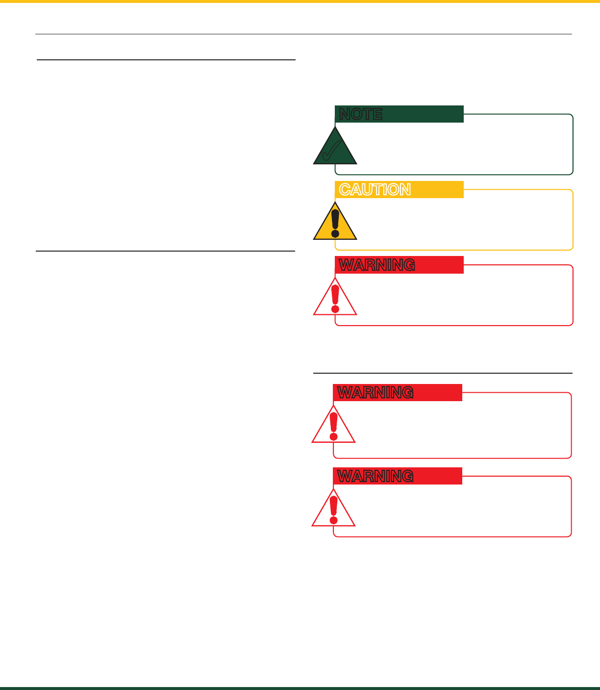
The following notations may be used in this
manual:
1.2d. Notifications Included in Document
hiNTS ANd TipS TO FACiLiTATE SySTEm
iNSTALLATiON Or uNdErSTANdiNg.
NOTE
✓
prOTECT yOurSELF AgAiNST prOduCT
pErFOrmANCE iSSuES, prOduCT FAiLurE,
ANd/Or prOpErTy dAmAgE.
CAUTION
prOTECT yOurSELF AgAiNST SEriOuS
iNJury Or dEATh.
WARNING
CArEFuLLy rEAd ANd uNdErSTANd ThiS
mANuAL BEFOrE prOCEEdiNg.
WARNING
ThE gS550 uNdErhOOK SySTEm iS
dESigNEd AS AN OpErATOr Aid ANd
iS iN NO wAy A SuBSTiTuTE FOr SAFE
OpErATiNg prACTiCES.
WARNING
1.3. Before You Begin
The GS550 Underhook creates a two-way radio
network with the sensors to bring required lift
data to the operator. Hoist load can be detected
and then indicated to the operator in real time.
Furthermore the GS550 Underhook can be
programmed to generate warnings and alarms, all
triggered by adjustable thresholds and limits. The
exact operational function of the GS550 Underhook
system depends on the sensor configuration used.
1.1 Introduction
GS550 UNDERHOOK
4 ChApTEr 2: iNSTALLATiON
InstallatIon must be made In
complIance wIth lsI-Robway
InstRuctIons and usIng lsI-Robway
supplIed components only.
FAiLurE TO iNSTALL ALL pArTS, Or
rEpLACiNg pArTS Or COmpONENTS wiTh
pArTS Or COmpONENTS NOT SuppLiEd
By LSI-ROBWAY, mAy LEAd TO SySTEm
FAiLurE, SEriOuS iNJury Or dEATh.
WARNING
2: iNSTALLATiON
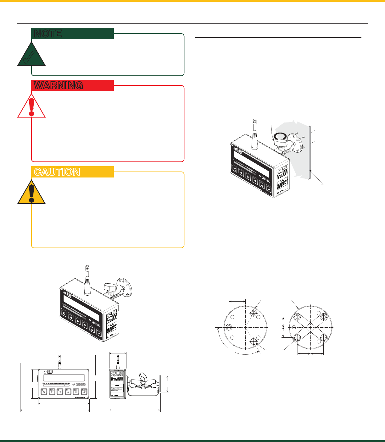
2.1 Display GS550 Underhook
2.1a Mounting Bracket
10.13
7.56
7.64
2.51
4.38
7.67 2.44
.MIL.RAT
MENU
GS550
%0 10 20 30 40 50 60 70 80 90 100 110
Figure: Display GS550 Underhook
Figure: Display dimensions (inches). Not to scale.
The GS550 Underhook is provided with a
mounting bracket that serves as an handle but
can also be mounted on a support following the
dimensions below.
The mounting bracket can also be fitted to any
Ram Mounts compatible accessories (1” ball).
a. Determine mounting location inside the cab. To
ensure reliable radio communication between
sensors and the GS550 Underhook, the
antenna should not be in contact with metal
and should have a direct and clear line of sight
to the sensor antenna.
b. Drill 1/4” boltholes through the mounting
surface with a 1/4” bit following either the two-,
three-, or four-hole configuration.
c. Install the display with bolts. Add washers and
lock nut behind mounting surface. Tighten
sufficiently. (Bolts, nuts, and washers not
included with assembly.)
d. Loosen wing nut of the bracket arm. Adjust
display orientation to facilitate operator viewing,
then retighten wing nut.
Figure: Display mounting bracket footprint. Not to scale.
Figure: Configuration options for Mounting Bracket.
.MIL.RAT
MENU
GS550
%0 10 20 30 40 50 60 70 80 90 100 110
Cab mounting
surface
Wing
Nut
rEFEr TO ThE OpErATiON SECTiON,
BEgiNNiNg ON p. 7, FOr dETAiLEd mENu
NAvigATiON iNSTruCTiONS FOr ALL
CALiBrATiON prOCEdurES.
NOTE
✓
do not cRack oR punctuRe the face
coveR membRane.
do not poweR wash the dIsplay.
ThE gS550 uNdErhOOK diSpLAy
iS SpLASh- ANd rAiN-prOOF.
wATErprOOFiNg dEpENdS iN pArT ON
ThE iNTEgriTy OF ThE mEmBrANE. pOwEr
wAShiNg wiLL vOid ThE wArrANTy.
CAUTION
0.750 0.750
0.906
ø0.218
ø2.5 in. min.
flat surface
120° TYP
0.594
0.594
GS550 UNDERHOOK
5
ChApTEr 2: iNSTALLATiON
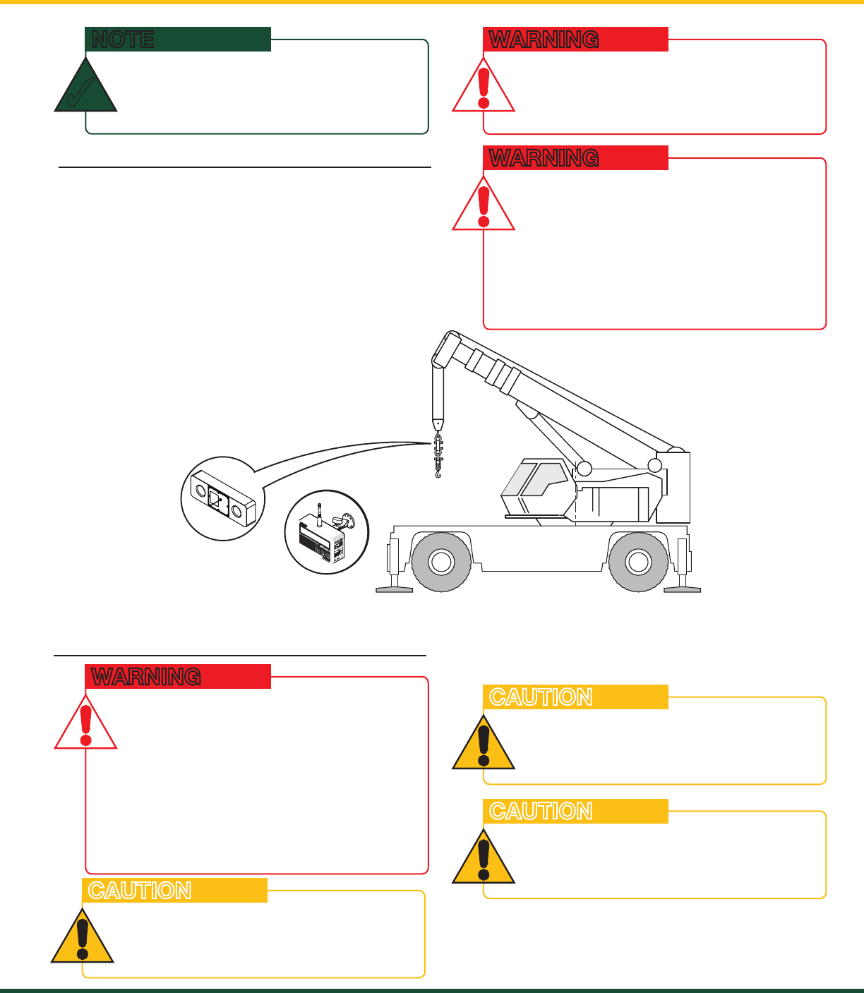
2.2 Start-Up
Figure: Key components in a typical system installation. Your product may vary. Not to scale.
Under Hook
GS550 Display
Load Cell
TAR. LIM.
MENU
GS550
%01020 30 40 50 60 70 80 90 100110
.
M
I
L
.
RAT
MENU
GS5 5 0
%0 10 20 30 40 50 60 70 80 90 1001
10
Underhook
.
M
IL
.RAT
MENU
GS5 5 0
%0 1020304050 60 70 80 90 100110
Underhook
ThE gS550 uNdErhOOK SySTEm iS
dESigNEd AS AN OpErATOr Aid ANd
iS iN NO wAy A SuBSTiTuTE FOr SAFE
OpErATiNg prACTiCES.
WARNING
InstallatIon must be made In
complIance wIth lsI-Robway
InstRuctIons and usIng lsI-Robway
supplIed components only.
FAiLurE TO iNSTALL ALL pArTS, Or
rEpLACiNg pArTS Or COmpONENTS wiTh
pArTS Or COmpONENTS NOT SuppLiEd
By LSI-ROBWAY, mAy LEAd TO SySTEm
FAiLurE, SEriOuS iNJury Or dEATh.
WARNING
The GS550 Underhook must be correctly
programmed for the system sensors installed. If a
sensor is missing or has a problem, a message will
be displayed on the GS550 Underhook. Press the
Info button to get more details on the problem.
This process may take up to one minute. The delay
is created by the battery management function.
Press and hold the Exit button to temporarily stop
the buzzer if needed.
iF ThE NuTS ArE ON ThE OuTSidE OF ThE
CAB, CAuLK wiTh SiLiCONE BETwEEN
ThE wAShErS ANd ThE CAB TO prEvENT
wATEr ENTry.
NOTE
✓
2.3 Load Cell
CApACiTy FOr LOAd CELLS ANd
ShACKLES/ACCESSOriES ArE
CALCuLATEd FOr LOAdS ALONg ThE
iNTENdEd AXiS OF LOAd (vErTiCAL ON
hOOK ASSEmBLiES, hOriZONTAL whErE
ApprOpriATE); SidE LOAdiNg Or TwiSTiNg
mAy CAuSE uNduE STrESS ON ThE LOAd
CELL/LiFTiNg ACCESSOriES CAuSiNg
LOAd drOpS. RIggIng must be done
In a way that twIstIng Is avoIded to
pRevent sIde loadIng.
WARNING
ThE LOAd CELL muST BE CENTErEd ON
ThE ShACKLE TO AvOid uNEvEN LOAdiNg
ON ThE pLATE KiT ASSEmBLy.
CAUTION
ThE LOAd CELL ANTENNA ShOuLd NOT BE
iN CONTACT wiTh mETAL.
CAUTION
FOr OpTimAL pErFOrmANCE ANd SigNAL
rECEpTiON, ENSurE A CLEAr LiNE OF
SighT BETwEEN ThE LOAd CELL ANTENNA
ANd ThE gS550 uNdErhOOK diSpLAy.
CAUTION
GS550 UNDERHOOK
6 ChApTEr 3: OpErATiON
3: OPErATiON
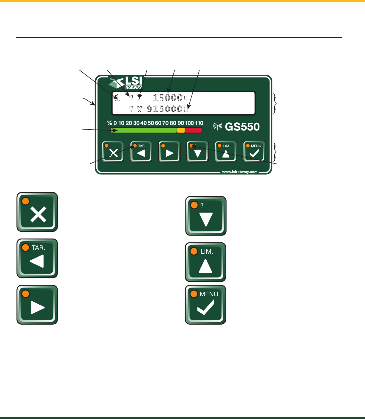
3.1 GS550 Underhook Display
The GS550 Underhook displays detailed information on the backlit, two line liquid crystal display (LCD);
warnings and alarms are also communicated by the display buzzer.
Exit /Alarm Bypass
Use this key to exit up from menus.
This button is also used as a
temporary Alarm override.
Tare / Back
Use Tare to zero any rigging weight.
Also used to navigate through
menu screens.
Next
Used in the menu to select next item.
Info / Down
When the orange light flashes,
press Info to see any critical alert
messages. Also used to move
numeric numbers and choices in
the menu.
Limit / Up
Set the overload alarm by pressing
this key.
Used in the menu to modify numeric
values / choices.
Menu / Enter
Access the system menus and also
used to confirm changes within.
Tare
Tare is used to eliminate rigging and slinging
weights, to do this do the following:
• Press TAR. Key
• Press Menu to select/deselect the Tare function.
• Press Exit to return to normal weighing mode.
Alarm/Overload
To set the Alarm setpoint, do the following:
• Press LIM. Key
• Change Flashing limit reading as required.
• Press Exit to return to normal weighing mode.
Liquid
Crystal
Display
(LCD)
USB Port
Bar Graph
Indicates the load
on the hoist as
a percent of the
working load limit.
Tare Warning Light
The total load is not displayed
when tare light is on.
Keypad
Info Alert Light
Press Info when the info
light flashes to see critical
alert messages.
Parts of line Hoist indicator Tare Indicator Load Working Load Limit
1 1 5 0 0 0
91 5 0 0 0
3.1a USB Port
The USB port is used to download data from the data logger or to upload a new firmware using a USB
mass storage device (USB key). For more information on how to use this, refer to section 5: USB Tool,
beginning on p. 15 of this manual.
GS550 UNDERHOOK
7
ChApTEr 3: OpErATiON
3.1b Tare
Zero the hook and rigging weight:
• Press Tare to enter the tare menu.
• Use Next to select the load sensor.
• If no tare value is displayed, then press Tare
to create a tare value equal to the weight on
the load sensor. Example: with hook block
and rigging only. Load display is net weight
(gross weight minus tare value).
• To remove a tare value, press Tare.
• Press Exit to return to the operation display.
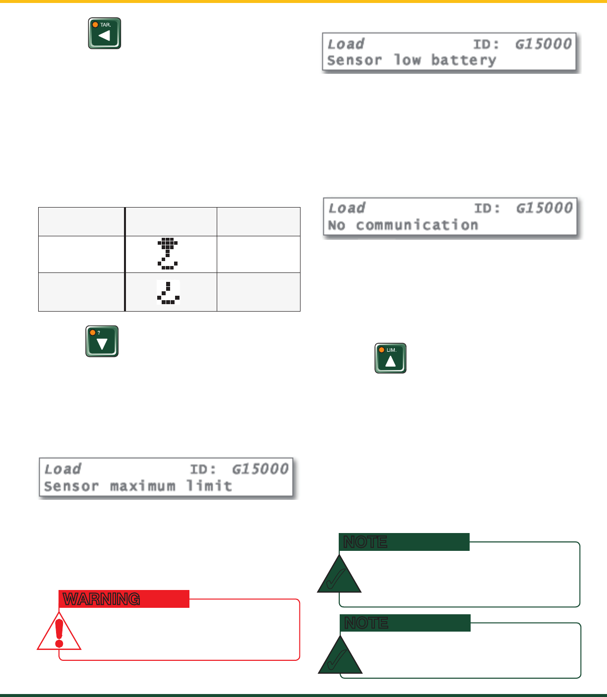
3.1c Info
Table: Information Menu Alerts
Description:
The sensor indicates a value greater than the
operator adjusted limit:
Verify operator adjusted limits in the limit menu.
Description:
Less than 10% of battery life remains in the sensor:
Schedule battery replacement for the next
available opportunity. Typically several weeks of
operation remain from the moment the sensor
low battery warning is first triggered.
Description:
The display is not receiving communication from
the sensor:
Verify that the sensor ID number programmed
matches the ID number of the sensor installed on
the crane. Go to menu 5A1.
3.1d Limit
Set Hoist Limits
Press Limit and then Enter to access the Sensor
Limits menu. The Sensor Limits menu displays
the limits for each sensor in the sensor list on
successive pages.
Use Next to scroll from one limit to the next.
Use Up and Down to adjust a limit.
When using GS550 Underhook, the load limit is
typically set to the lesser of the rope limit and the
hoist limit.
lcd
IndIcatoR
lcd load
No Tare Value Gross Weight
Tare Value Net Weight
Press Info to see critical system alerts and battery
status. Press Next to advance from one page to
the next.
Standard info menu pages include firmware
number and version
Alert:
Alert:
dO NOT OpErATE ThE CrANE BEyONd ThE
LimiTS SpECiFiEd By ThE mANuFACTurEr.
WARNING
prESSiNg up ANd dOwN SimuLTANEOuSLy
wiLL rETurN A LimiT TO ThE FACTOry dEFAuLT
SETTiNg. ThE FACTOry dEFAuLT mAXimum
LimiT FOr LOAd SENSOrS iS 10,000 LB.
NOTE
✓
whEN ThE wEighT uNiTS ArE TONS, ThE
miNimum LOAd LimiT iNCrEmENT iS 0.1 TON.
NOTE
✓
GS550 UNDERHOOK
8 ChApTEr 3: OpErATiON
3.4b Menu Navigation
From the operation display press Menu to see the
basic menus (level one). Press Enter to drill down
one level and enter a selected menu. Press Exit to
leave a menu and return up one level. Press Next
to move to the next page within a menu; press
Back to move to the previous page within a menu.
Use Up and Down to modify numeric values and to
move through a list of choices.
3.4c Password Protection
The submenus of menu 4) Installation are
protected by a password by default. Password
settings can be adjusted in menu 4H) Password
Settings. If the user password is forgotten, it can
be changed as long as the administrator password
is known.
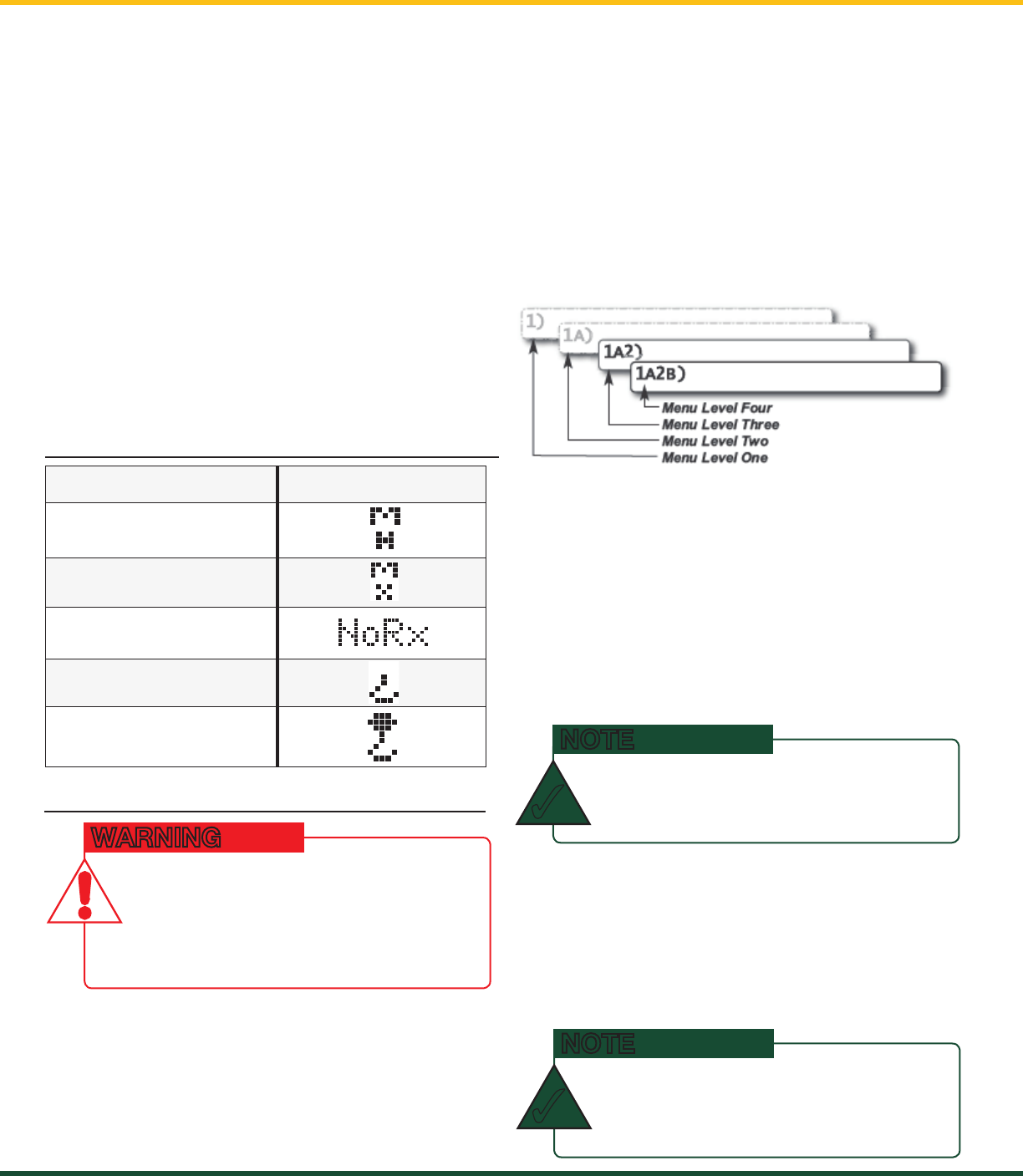
3.4a Menu Numbers
Menus are identified by a number in the upper left
corner. The basic menus (level one) are numbered
one through five. Level two menus are lettered
alphabetically. Level three menus are numbered.
Level four menus are alphabetized.
Figure: Menu Numbers
The basic menus include nested sub-menus (levels
two, three and four) designed to address specific
tasks including adjusting values, choosing from
lists and following “wizards” to navigate step-by-
step processes.
3.3 Display abbreviations
Item symbol
Main hoist
Maximum
Communication not
established
Tare (net weight)
Gross weight
3.4 System Menu
There are four basic menus (level one) used
to program, consult and control the GS550
Underhook system:
1) Parts of Line;
3) Display Settings;
4) Installation;
5) System Diagnostic.
system lImIts aRe not monItoRed
when the dIsplay Is In menu mode.
dO NOT OpErATE ThE CrANE LiFTiNg
mAChiNEry iN mENu mOdE. dO NOT
NAvigATE SySTEm mENuS whiLE
OpErATiNg ThE CrANE.
WARNING
most menus and lIsts aRe cIRculaR.
prESS NEXT/dOwN ON ThE LAST ENTry TO
rETurN TO ThE FirST.
NOTE
✓
foRgot youR passwoRd?
CALL LSi-rOBwAy TEChNiCAL SuppOrT
(rEFEr TO ThE BACK COvEr OF ThiS
mANuAL FOr iNFOrmATiON).
NOTE
✓
3.1e Parts of Line
The load sensor often shares the weight with
multiple parts of line. For accurate load indication
the GS550 must be programmed for the number
of parts of line.
1. Go to menu 1) Parts of Line.
2. Use Next and Back to select the load sensor;
typically sensor number one is associated with
sheave one (the main hoist) and sensor number
two is associated with sheave two (the auxiliary
hoist) etc.
3. Use Up and Down to adjust the number of
parts of line.
4. Press Enter to save any changes. Press Exit
twice to return to the operation display.

GS550 UNDERHOOK
9
ChApTEr 3: OpErATiON
3.4d GS550 Underhook Menu Outline
1) Parts of Line*
3) Display Settings*
3A) Weight units*
3C) Display language*
3D) Light intensity*
3E) LCD contrast*
3F) Backlight mode*
4) Installation*
4A) Sensor List
4A1) Sensor type and radio identification number
4A2) System selected configuration number
4A3) Configuration number selection mode
4B) Sensor Calibration
4B1) Automatic value calibration wizard
4B2) Manual parameter calibration
4B3) Reset sensor parameters
4F) Data Logger
4F1) Data logger mode
4F2) Adjust date
4F3) Adjust time
4G) Lockout Settings
4G1) Warning level
4G2) Alarm level
4H) Password Settings
4H1) Set administrator password
4H2) Set user password
4H3) Tare menu password protection
4H4) Limit menu password protection
4H5) Info menu password protection
4H6) System start-up password protection
4H7) Parts of Line menu password protection
4H9) Display Settings password protection
4H10) Sensor List password protection
4H11) Sensor Calibration password protection
4H15) Data logger password protection
4H16) Lockout Settings password protection
4H18) System Diagnostic password protection
4H19) Alarm Bypassed protection
4I) Network Options
4I1) Display mode
4I2) Set-up sensor repeater
4I3) Last repeater programmed
4I4) Install update
5) System Diagnostic*
5A) System Sensors Diagnostic*
5B) Radio Network Diagnostic*
5B1) Radio network background noise*
5B2) List last 32 sensors received*
5B3) Search for sensors*
5D) Display Diagnostic*
5D1) Time and date*
5D2) Time clock battery test*
5D3) External power supply voltage*
5D4) Internal temperature*
5D5) GS550 base station identification number*
5D6) GS550 power source / battery level*
5D7) Radio (certification and frequency)*
Only sections relevant to Underhook operation have been listed.
Menu levels with an asterisk (*) after the title are accessible to the operator without a password under the
default factory settings.
GS550 UNDERHOOK
10 ChApTEr 4: SETup
4.2a How to Add a Sensor to the GS550 Underhook
1. Determine the radio identification number (ID) of
the sensor to be added. This number between
10000 and 999999 is engraved on the sensor.
2. Go to menu page 4A1).
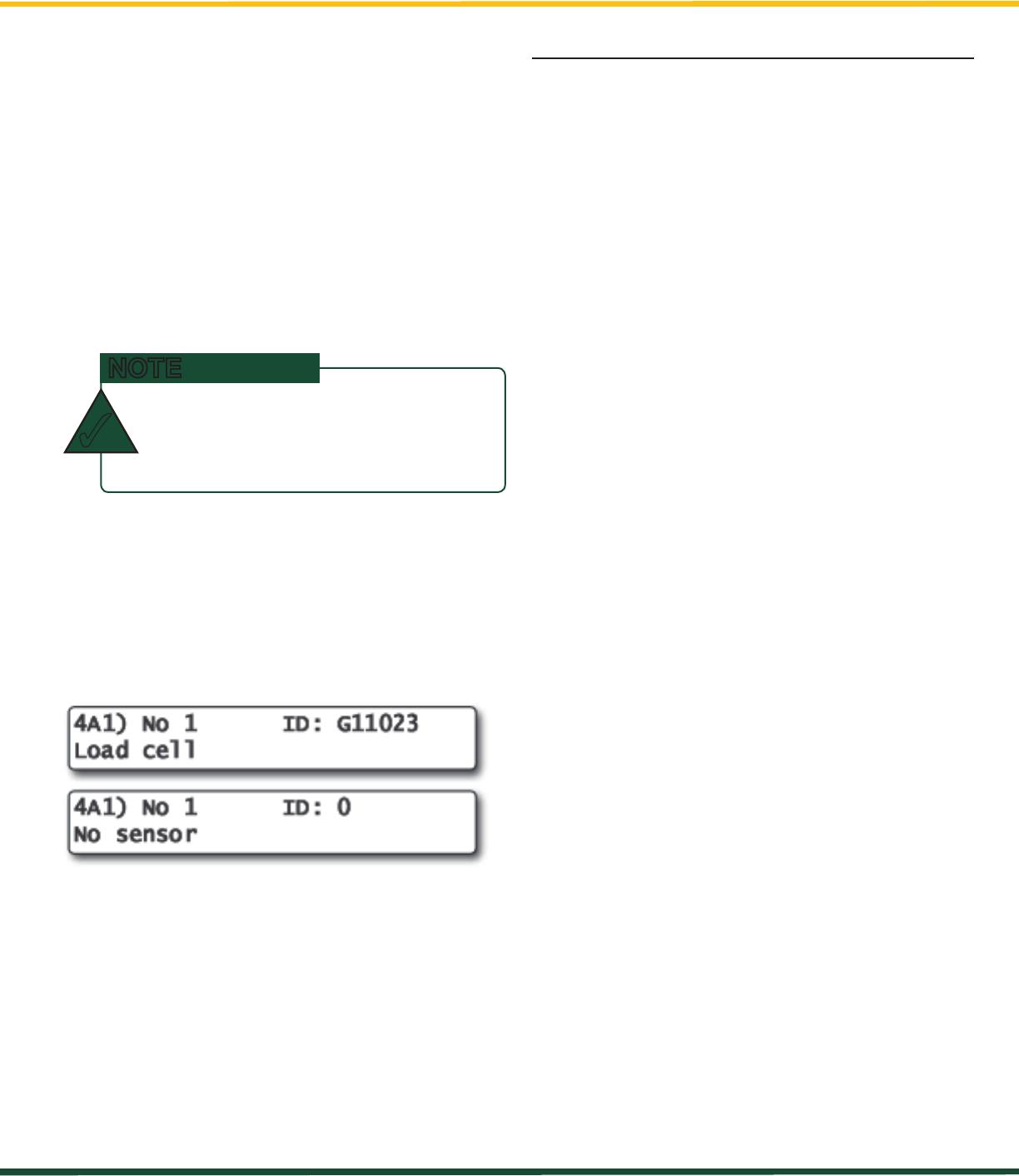
3. Advance to the next empty sensor position in
the sensor list. Press Next repeatedly until the
LCD shows “No sensor” on the bottom line.
Up to four (4) load cells and one (1) summation
may be added to the sensor list.
4. The ID number should flash; this means it is
adjustable. Use Up and Down to program
each sensor ID.
5. Press Next.
6. The sensor type (“No sensor”) should flash;
this means it is adjustable. Use Up and Down
to select the sensor type.
7. Press Enter to save any changes made to the
sensor list.
8. Press Exit three times to return to the main
operation display.
4.1 Sum Load Indication
When sum load indication is programmed the sum
of the loads on the pre-determined load sensors is
indicated by the operation display. To activate sum
load indication program a “Sum load cell” in the
sensor list. The “ID number” is used to identify the
load sensors to be summed.
Sum maximum limit. The maximum limit
for the sum load can be adjusted in the limit
menu; the default maximum limit for sum load
indication is 10,000 lbs or 4,535 kg.
Program sum load indication:
1. Go to menu 4A1) Sensor list.
2. Press Next repeatedly to advance to the next
available sensor position, usually following the
four load sensors.
3. Determine the sum load cell “ID number”. For
example: ID 1234 to indicate the sum of load
sensors No. 1, No. 2, No. 3, and No. 4, or
ID 34 to indicate the sum of load sensors No. 3
and No. 4.
4. Use Up and Down to adjust the ID number.
5. Press Next.
6. The sensor type should flash; use Up and
Down to select the sensor type “Sum load cell.”
7. Press Enter to save any changes.
8. Press Next to program the imbalance sensor
or press Exit three times to return to the
operation display.
9. Adjust the sum maximum limit in the limit menu.
4.2 Sensor List
All sensors in the GS550 Underhook system
are programmed in the sensor list. The GS550
Underhook uses information from all sensors in the
sensor list. Conversely the GS550 Underhook will
not use or display information from sensors that
are not programmed to the sensor list. If a sensor
is removed from the crane then it must be removed
from the sensor list. If a sensor is replaced the
sensor list must be updated with the new ID number.
4: SETUP
TO ENSurE COmmuNiCATiON, SENSOrS
muST BE AT LEAST SiX FEET FrOm ThE
gS550 uNdErhOOK diSpLAy.
NOTE
✓
pRessIng the up and down buttons
sImultaneously wIll go dIRectly to
a paRtIculaR numbeR:
prESSEd ONCE: TO NumBEr 30000
prESSEd TwiCE: TO NumBEr 25000
prESSEd ThrEE TimES: TO NumBEr 0
NOTE
✓
GS550 UNDERHOOK
11
ChApTEr 4: SETup
4.2b How to Remove a Sensor from the GS550
Underhook
1. Determine the sensor to be removed. If more
than one sensor of the same type has been
added to the sensor list then determine the
radio identification number (ID) of the sensor
to be removed before proceeding. A sensor
ID number between 10000 and 999999 is
engraved on each sensor.
2. Go to menu page 4A1).
3. Press Next repeatedly to advance to the page
of the sensor list showing the ID of the sensor
to be removed.
4. The sensor ID should flash, press Next, the
sensor type should flash; this means it is
adjustable. Use Up and Down to select “No
sensor”. This will remove the sensor from the
sensor list but retain the sensor ID.
5. Press Enter to save any changes made.
6. Press Exit three times to return to the display.
Figure: Menu 1A) - the sensor list
4.3 Password Settings
Two levels of access are available: administrator
and user. The administrator password is required
to change the user password. In the event both
the administrator and the user passwords are lost
please call LSI-Robway technical support. Menus
accessible from the operation display can be
individually protected by the user password.
1. Go to menu 4H1) Set administrator password.
2. Menu 4H1) Set administrator password: Press
Next three times to advance to the set user
password page or, to change the administrator
password, use Up and Down to adjust the
flashing letter and then use Next to advance to
the next letter. Press Enter to save changes.
3. Menu 4H2) Set user password: Press Next
three times to advance to the tare menu
protection page or, to change the user
password, use Up and Down to adjust the
flashing letter and then use Next to advance to
the next letter. Press Enter to save changes.
4. Menu 4H3) Tare protected: use Up and Down
to switch between “YES” and “NO” and press
Next to advance to the next menu page.
5. Repeat step 4 to adjust password protection
for each menu as required. Press Enter at
any time to save changes made. Press Exit
at any time to return to menu 4) Installation.
If there are any unsaved changes the display
will request confirmation: press Enter to save
before quitting or press Exit to quit without
saving.
prESS next ANd back SimuLTANEOuSLy
TO rEmOvE ThE SENSOr FrOm ThE
SENSOr LiST. ThE id NumBEr wiLL rEvErT
TO 0 ANd ThE SENSOr TypE wiLL rEvErT
TO “NO SENSOr.”
NOTE
✓
GS550 UNDERHOOK
12 ChApTEr 4: SETup
4.4 Data Logger
The GS550 Underhook includes a data logger
that records all significant events including actual
sensor values and a date and time stamp. The
data logger memory can hold over 16,000
records, equivalent to several days or several
years of operation depending on the recording
mode selected and machine use. The data can be
extracted using a USB mass storage device (USB
key) and then transferred to a personal computer
for analysis.
4.4a Recording Modes
1. Go to menu 4F1) Data logger mode.
2. Use Up and Down to select the data logger
recording mode.
3. Automatic modes only: press Next to
advance to the adjustment page for the
interval (automatic recording mode), variation
(automatic variation recording mode), or
threshold (automatic peak recording mode).
4. Press Enter to save any changes.
5. Press Exit three times to return to the operation
display or press Next to adjust the data logger.
Adjust the data logger recording mode as required:
Recording Modes description:
Alarm only: Record alarms only. All the other
data logger modes also record alarms.
All data: All communications between a display
and its sensors are recorded.
User input: This option is not available for the
GS550 Underhook.
Automatic peak: In the automatic peak mode
the data logger analyzes the measured weight
and records the peak value only. One threshold
per load cell must be adjusted. When the weight
drops by more than the peak threshold the peak
weight is recorded. Only one event is recorded
for each pick when the threshold is adjusted
correctly. When the automatic peak data logger
mode is selected on menu 4F1 (see step 3
above) press Next to go to menu 4F1) and then
use Up and Down to adjust the peak threshold
for the first load cell. Press Next to repeat for the
second load cell etc. Up to four load cells can be
programmed for automatic peak data logging.
Automatic recording: A record is added at a
specified interval. When the automatic recording
data logger mode is selected on menu 4F1 (see
step 3 above) press Next to go to menu 4F11)
and then use Up and Down to adjust the record
interval in seconds.
Automatic variation: A record is added when
load increases by more than the operator
adjusted percentage. When the automatic
variation data logger mode is selected on menu
4F1 (see step 3 above) press Next to go to menu
4F11) and then use Up and Down to adjust the
variation threshold.
4.4b Date and Time
Adjust the data logger date and time as required:
1. Go to menu 4F2) Adjust date.
2. The last two digits of the year should be
flashing: use Up and Down to adjust the year.
3. Press Next to adjust the month.
4. Use Up and Down to adjust the month.
5. Press Next to adjust the day.
6. Use Up and Down to adjust the day.
7. Press Next to adjust the time.
8. The hour should be flashing: use Up and
Down to adjust the hour from 00 (midnight) to
23 (11 pm).
9. Press Next to adjust the minute.
10. Use Up and Down to adjust the minute.
11. Press Next to adjust the second.
12. Use Up and Down to adjust the second.
13. Press Enter to save any changes.
14. Press Exit three times to return to the
operation display.
ALL ALErTS ArE rECOrdEd By ThE dATA
LOggEr rEgArdLESS OF ThE rECOrdiNg
mOdE SELECTEd.
NOTE
✓

GS550 UNDERHOOK
13
ChApTEr 4: SETup
4.5 Display Settings
Program the display for operator preferences in
menu 3) Display Settings.
4.5a Weight Units
The weight units for load display may be selected
according to operator preference. Length units are
associated with weight units by default; see the
table below.
1. Go to menu 3A) Weight units.
2. Use Up and Down to select the weight units
for load display.
3. Press Menu to save changes. Press Next to
advance to the language adjustment page or
press Exit twice to return to the main display.
Table: Weight Units
unIt equIvalent weIght
Pound (lb) 1 lb 0.4536 kg
Kilogram (kg) 2.205 lb 1 kg
Short ton (t)
United States
2000 lb 907.2 kg
Long ton (T)
United Kingdom
2240 lb 1016 kg
Tonne (t)
International
System (SI)
2205 lb 1000 kg
Kilopound (kip) 1000 lb 453.6 kg
Kilonewton 224.81 lb 101.97 kg
4.5b Language
1. Go to menu 3C) Display language.
2. Press Up and Down to change the display’s
operating language.
4.5c Contrast
Adjust the LCD contrast to optimize visibility.
1. Go to menu 3E) LCD contrast adjustment.
2. Use the Up and Down buttons to adjust the
display contrast.
3. Press Next to advance to the backlight
adjustment page or press Exit twice to return
to the operation display.
4.5d Backlight Mode
Adjust the LCD backlight control mode to conform
to viewing and power supply conditions.
1. Go to menu 3F) Backlight mode.
2. Use Up and Down to select the backlight
control mode. The LCD backlight can be
always on, always off, or on a four second
timer. In the four second timer mode the
backlight will come on for four seconds when
any button is pressed.
3. Press Menu to save changes, then press Next
to advance to the backlight adjustment page or
press Exit twice to return to the main display.
4.5e Light Intensity
Adjust the intensity of the LEDs (light emitting
diodes) to facilitate viewing in bright sunlight or in
reduced visibility:
1. Go to menu 3D) Light intensity adjustment.
2. Use Up and Down to adjust the intensity of the
lights on the display.
3. Press Menu to save changes, then press Next
to advance to the contrast adjustment page or
press Exit twice to return to the main display.
GS550 UNDERHOOK
14 ChApTEr 4: SETup
4.6 System Diagnostic
Diagnose system issues with the sub menus of
menu 5) System Diagnostic.
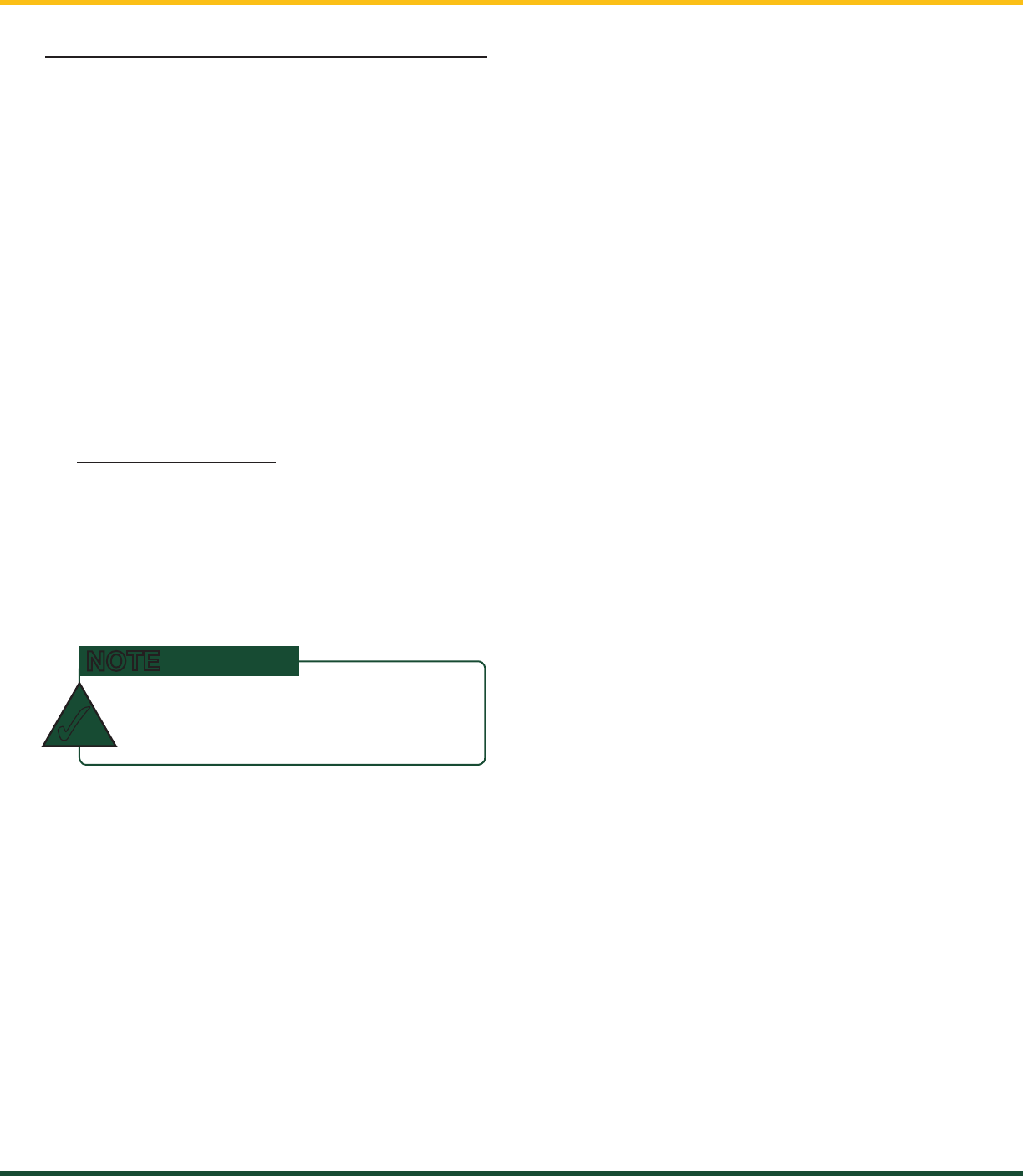
4.6a System Sensors Diagnostic
1. Go to menu 5A1).
2. Use Back and Next to select the sensor.
3. Press Enter to see sensor data.
4. Press Enter to get the sensor firmware product
and version numbers.
5. Press Exit five times to return to the main
operation display.
4.6b Display Diagnostic
1. Go to menu 5D1) Time and Date. The page
shows the current time and date according to
the GS550 internal clock.
2. Press Next to go to menu 5D2) Time clock
battery. Self-test pass or fail.
3. Press Next to go to menu 5D3) External
power voltage.
4. Press Next to go to menu 5D4) Display
internal temperature.
5. Press Next to go to menu 5D5) GS550 base
station ID. The base station ID should be
the same as the GS550 display serial number
printed on the top of the enclosure.
6. Press Next to go to menu 5D6) Battery level.
The battery level of the onboard rechargeable
battery pack is indicated.
7. Press Next to go to menu 5D7) Radio.
“FCC”, “IC” indicates Federal Communications
Commission (U.S.A.) and Industry Canada
certification, “CE” indicates European
Community certification. The frequency used by
the network is indicated on the second line.
8. Press Exit three times to return to the main
operation display.
GS550 UNDERHOOK
15
ChApTEr 5: uSB TOOL
5: USB TOOL
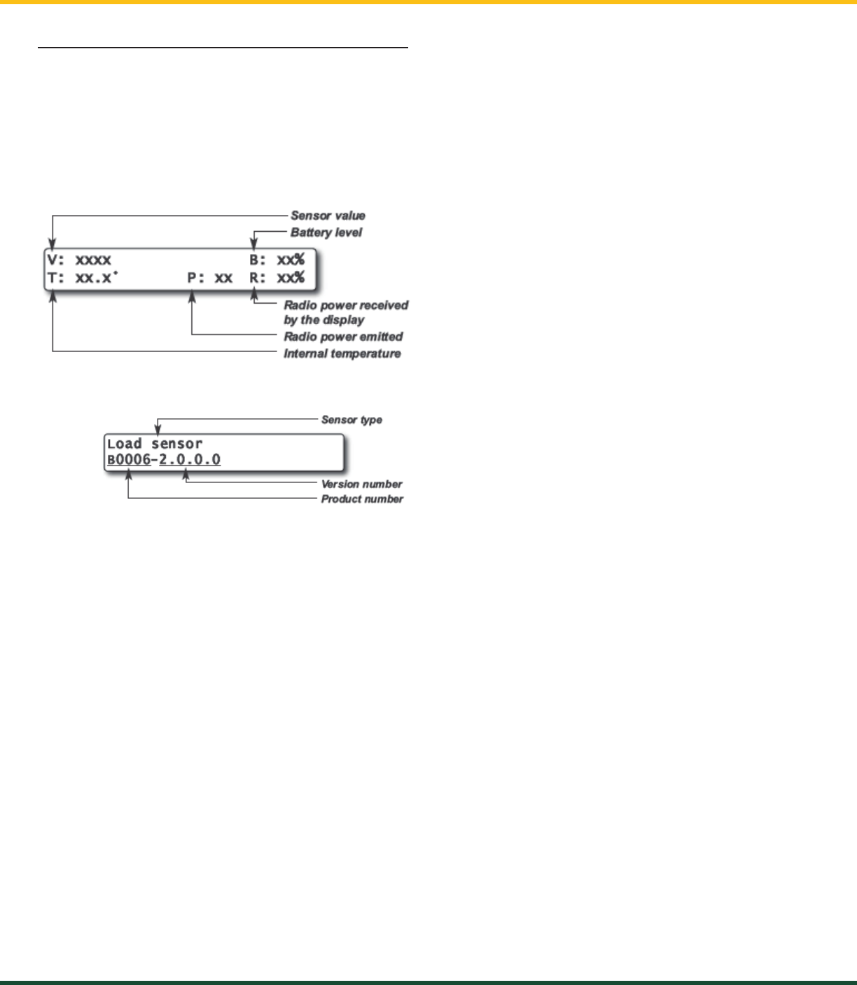
Download data or upload capacity charts using a
USB mass storage device (USB key).
Figure: Transfer charts or data logger files
5.1 Data logger transfer from Display
5.1a Transfer from display to USB device
1. Make sure there is at least 4 MB of available
space on the USB key. Connect the USB key in
the USB port, on the left side of the display.
2. After a short delay (about 2 seconds), “Copy
datalog to USB” will appear on the LCD; press
Enter to continue.
3. In most case, you will be prompted to enter a
password; enter the download password given
by LSI-Robway and press Enter.
4. Press Enter once again to confirm the data
logger download “Data logger - Enter to
transfer.” This will begin the transfer.
5. Transfer progress is indicated on screen.
6. When the transfer is done, “Transfer successful”
will appear for 2 seconds. Unplug the USB
device. The GS550 Underhook will restart.
7. The crane is now ready for operation.
Figure: Update firmware or download data logger files
5.1b Transfer from USB device to PC
1. Connect the USB device to a computer.
2. The data logger file is located in the root
directory of the USB device:
“LSI_MM_dd_yyyy_hh_mm_ss.dtl” where the
double letters represent the time and date of the
USB transfer. The size of the USB transfer file
should be 4096 kb.
USB Port
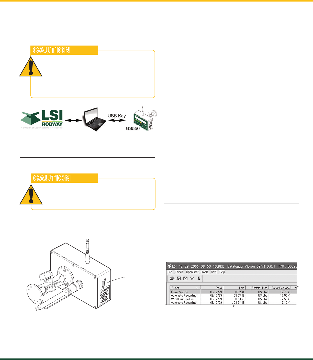
5.2 Data Logger Viewer
The data logger viewer is a software application
used to display the data logger log file on a
personal computer (PC).
The data logger viewer converts the log file to a
text (binary) file, and then displays the contents.
Two reports can be produced and transferred to
Excel, the full report and the wind speed report.
Figure: Data Logger Viewer
the load cannot be monItoRed
duRIng the download pRocess.
BEFOrE TrANSFErriNg (Or
dOwNLOAdiNg) dATA LOggEr Or
FirmwArE updATES, mAKE SurE ThE
CrANE/mAChiNEry iS STOppEd ANd iS iN
A SAFE STATE.
CAUTION
FOr OpTimAL pErFOrmANCE ANd SigNAL
rECEpTiON, ThE LOAd CELL ANTENNA
ShOuLd hAvE A CLEAr LiNE OF SighT TO
ThE gS550 uNdErhOOK diSpLAy.
CAUTION