Load Systems GS002 GS025: Radio Anemometer, GS085: Radio Ant-Two-Block User Manual for GS085
Load Systems International, Inc. GS025: Radio Anemometer, GS085: Radio Ant-Two-Block for GS085
Contents
- 1. user manual for GS025
- 2. user manual for GS085
user manual for GS085
GM085_ENG_rev.docx www.loadsystems.com 1
WIRELESS TECHNOLOGY & CRANE INSTRUMENTATION
DIVISIONS
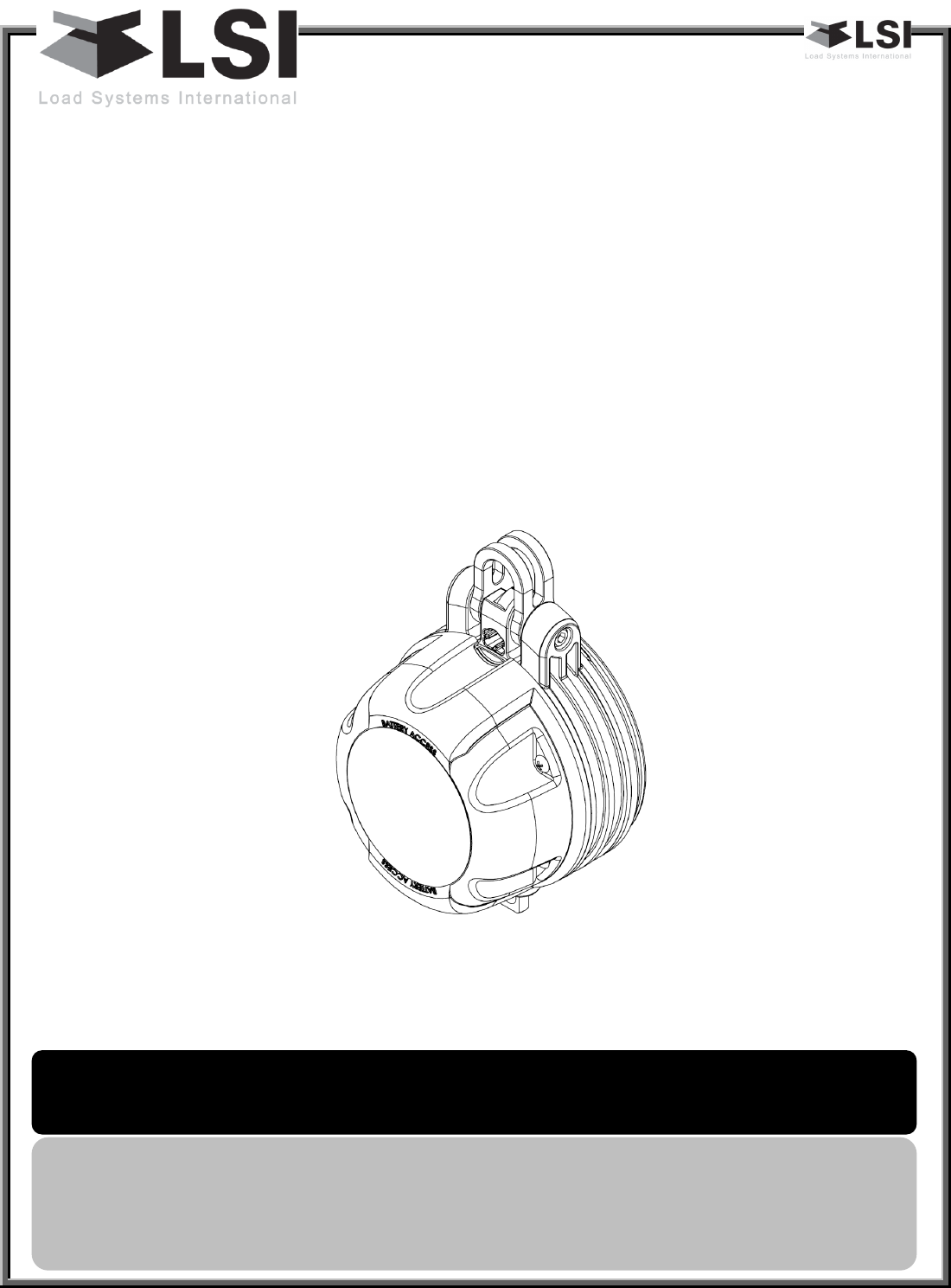
GS085
Radio Anti-Two-Block
I
In
ns
st
ta
al
ll
le
er
r
a
an
nd
d
u
us
se
er
r
g
gu
ui
id
de
e
WARNING
! Carefully read and understand this manual and the
GS320/GS550/GS820 Installer and User’s manual before proceeding.
Manual before proceeding.
IMPORTANT!
Refer to the “GS375/GS550/GS820 Display & GS Series
Sensors - Installer and User’s Manual” for complete information about
installation, operation, maintenance, certification and warranty.
GM085_ENG_rev.docx www.loadsystems.com 2
Read and understand the following:
For your safety and that of the people that come into contact with LSI products, understand
the significance of the instructions included in this guide, respect all laws and regulations
and comply with applicable standards.
Pay particular attention to text boxes and the following words:
Warning: this denotes an instruction that if not complied with may lead to serious injury or
death.
Important: this denotes an instruction that if not complied with may lead to product
performance issues.
1. Overview ....................................................................................................................................... 3
2. Switch Bracket Installation LB011 ................................................................................................. 3
3. GS085 Installation ......................................................................................................................... 4
4. Chain length adjustment ............................................................................................................... 4
5. Operation ...................................................................................................................................... 5
6. Security ......................................................................................................................................... 5
7. Battery replacement ..................................................................................................................... 5
Table of contents
WARNING!
Installation must be made in compliance with
LSI
instructions and using
LSI
supplied components only. Failure to install all parts, or replacing parts or
components with parts or components not supplied by
LSI
, may lead to system
failure, serious injury or death.
IMPORTANT!
WARNING!
BEFORE PROCEEDING
GM085_ENG_rev.docx www.loadsystems.com 3
1. Overview
The anti-two-block switch comprises of
the radio transmitter, battery and switch
mechanism. The switch mounts at the
boom tip. A weight and chain assembly is
attached to the bottom piston rod of the
A2B switch. When the weight assembly is
lifted by the ball/block, the internal switch
in the A2B will trip an alarm, warning the
operator of a two-block event.
The switch mounting bracket design
allows the switch to rotate in two axes.
The quick slip design of the mounting
bracket allows the switch to easily be
added or removed from the switch
mounting bracket without the need for
tools.
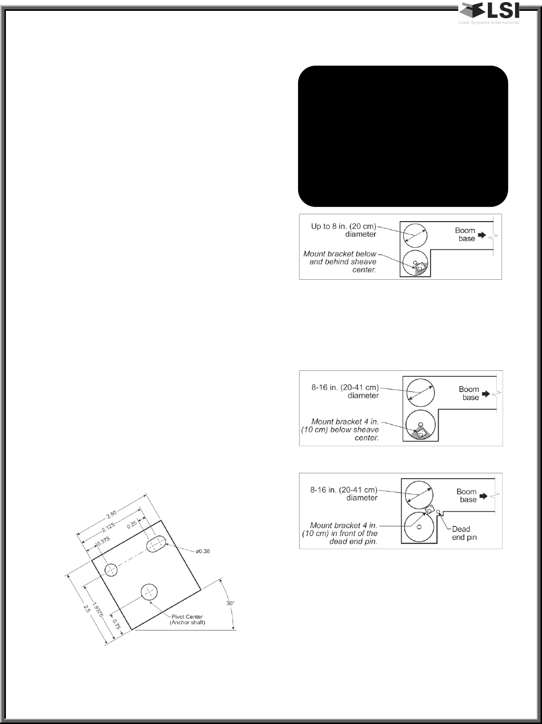
2. Switch Bracket Installation
LB011
Position the sensor mounting bracket. To
ensure that the sensor can pivot securely
on the mounting bracket throughout the
full range of boom angle, the mounting
bracket must be positioned at a 30° from
horizontal with the boom parallel to the
ground and such that the locking pin of
the mounting bracket points up. Bolt or
weld securely.
Figure 1: Bracket footprint and orientation, all
dimensions in inches, not to scale
Figure 2: Anti-two-block switch placement on a
telescopic boom
If the head sheave diameter is between 8
and 16 inches (20-41 centimetres) then
two mounting brackets will be required to
permit both live and dead end mounting.
Figure 3: Anti-two-block switch placement for live end
mounting on a latice boom
Figure 4: Anti-two-block switch placement for dead
end mounting on a lattice boom
For live end mounting on multiple sheave
blocks with sheaves greater than 16
inches (41 centimetres) in diameter
consult your service representative.
WARNING! Keep the anti-two-
block switch away from the boom
and any connecting metal
structures when welding mounting
brackets to the boom. Proximity to
welding may cause permanent
damage to the anti-two-block
switch and render the anti-two-
block system unsafe.
GM085_ENG_rev.docx www.loadsystems.com 4
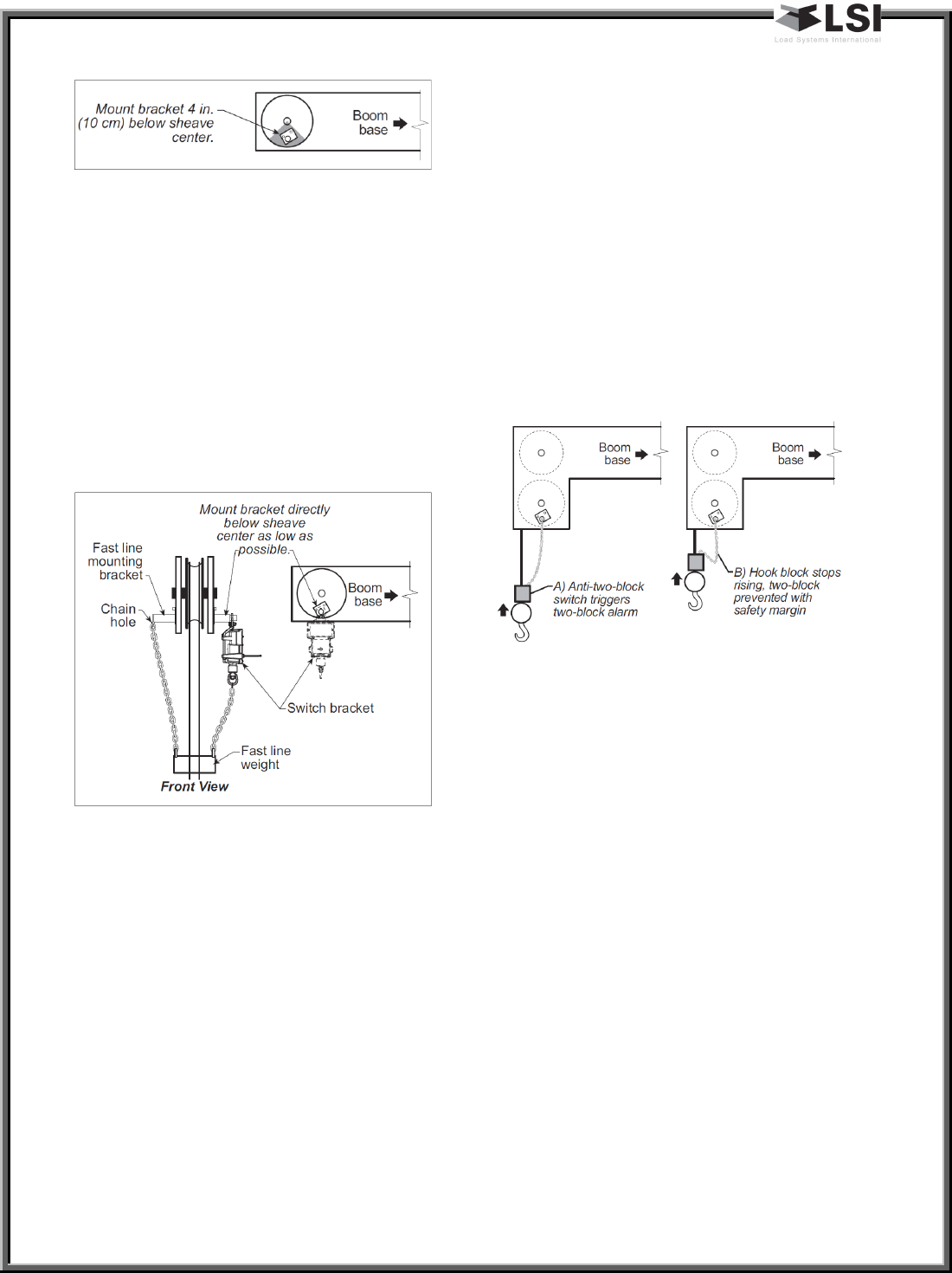
Figure 5: Jib, rooster or other extension: anti-two-block
switch placement for single part of line operation only
For fast line weight installation place the
anti-twoblock switch mounting bracket
directly below the sheave center as low
and as close to the edge of the sheave as
possible. Place the fast line weight
mounting bracket on the opposite side of
the sheave with the chain hole pointing
down and lined up opposite the pivot of
the anti-two-block switch mounting
bracket.
Figure 6: Fast line weight installation
3. GS085 Installation
Install the GS085 on the LB011 (switch
bracket) already installed on the crane
boom(step 2), with the battery cover
pointing away from the boom.
Install a weight and chain assembly to the
eye nut. The weight and chain assembly
can either be supplied by LSI (as an
option) or the original assembly supplied
with the crane. If the original assembly is
to be used, its total weight must not be
more than 13lb and the chain weight
must not exceed 2lb.
4. Chain length adjustment
Chain length adjustment No.1 – minimum
boom angle
a. At minimum boom angle, with no
additional weight on the hook
block and one part of line only, lift
the boom just enough to have the
hook block off the ground and
clear the sensor chain and weight.
Figure 7: Chain length adjustment - Minimum boom
angle
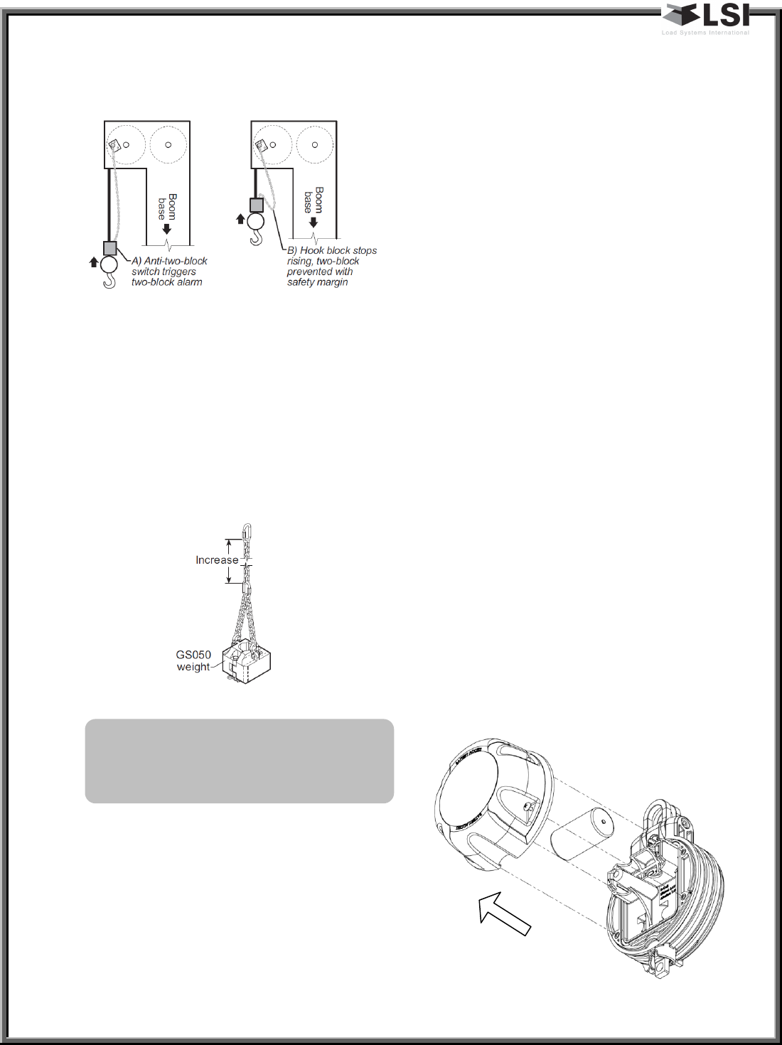
b. Hoist slowly until the buzzer
sounds. Note the hoisting distance
remaining; this distance must be
great enough to allow the
operator and the lockout system,
if installed, to prevent a two-block
event. If necessary, add chain
between the sensor and weight to
increase warning distance. If still
insufficient, contact your service
representative.
Chain length adjustment No.2 – maximum
boom angle
a. Raise the boom to the maximum
angle.
b. Hoist slowly as described in Step
1.b. Verify that the warning
distance is equal to or greater than
GM085_ENG_rev.docx www.loadsystems.com 5
that determined at the minimum
boom angle.
Figure 8: Chain length adjustment - Maximum boom
angle
Chain length adjustment No.3 – speed
test: Lower the boom until the weight
height becomes visually clear to the
operator. Repeatedly create two-block,
progressively hoisting faster, to ensure
that the warning and lockout work within
acceptable amount of time and distance.
Increase the length of the chain if needed.
Figure 9: Chain length adjustment
5. Operation
The radio anti-two-block is fully
functional. It does not need to be
calibrated or adjusted.
Refer to the GS375/GS550/GS820 manual
for how to add this sensor to the sensor
list to be displayed.
6. Security
The radio anti-two-block is equipped with
a failsafe power system allowing it to
instantaneously communicate an alarm
via radio signals if the battery of the
power circuit is rendered inoperative.
In the advent of a radio failure, the radio
communication protocol will generate an
alarm within 5 minutes of the loss of
signal.
7. Battery replacement
After a period of about 4 years, the
battery may need to be replaced. To
ensure the same performance as the
supplied battery, replace with:
3.6V lithium D cell
If this type of battery is not available, this
type can be used but with a reduced life:
1.5V Alkaline D cell
To replace a battery, unscrew the 4 cover
bolts of the battery cover and remove it.
Change the battery, verify that the o-ring
is clean & in good shape and re-install the
battery cover.
IMPORTANT!
To increase chain length, only use
lightweight chain

GM085_ENG_rev.docx www.loadsystems.com 6
8. FCC and IC – Instructions to
the User
This equipment has been tested and
found to comply with the limits for a class
B digital device, pursuant to part 15 of the
FCC Rules. These limits are designed to
provide reasonable protection against
harmful interference in a residential
installation. This equipment generates,
uses, and can radiate radiofrequency
energy and if not installed and used in
accordance with the instructions, may
cause harmful interference to radio
communications. However, there is no
guarantee that interference will not occur
in a particular installation. If this
equipment does cause harmful
interference to radio or television
reception, which can be determined by
turning the equipment off and on, the
user is encouraged to try to correct the
interference by one or more of the
following measures:
• Reorient or relocate the receiving
antenna.
• Increase the separation between the
equipment and receiver.
• Connect the equipment into an outlet
on a circuit different from that to which
the receiver is connected.
• Consult the dealer or an experienced
radio/TV technician for help.
In order to maintain compliance with FCC
regulations, shielded cables must be used
with this equipment. Operation with non-
approved equipment or unshielded cables
is likely to result in interference to radio
and TV reception.
IMPORTANT!
Changes or modifications to this
equipment not expressly approved by
the party responsible for compliance
could void the user’s authority to
operate the equipment.
FCC ID: QVBGS002 IC: 7076A-ICGS002
RF Exposure Warning:
This product complies with FCC/IC
radiation exposure limits set forth for an
uncontrolled environment. To comply
with RF exposure requirements, the unit
must be installed and operated with 20
cm (8 in.) or more between the product
and your body. This product may not be
collocated or operated in conjunction
with any other antenna or transmitter.
This device complies with Industry Canada
licence-exempt RSS standard(s).
Operation is subject to the following two
conditions: (1) this device may not cause
interference, and (2) this device must
accept any interference, including
interference that may cause undesired
operation of the device.
This Class A digital apparatus complies
with Canadian ICES-003.
GM085_ENG_rev.docx www.loadsystems.com
Technical support :
LSI Technical Support is available 24 hours a day, 7 days a week from our Houston and Dubai locations.
Please direct all technical support questions to either of these locations or contact us via email:
techsupport@loadsystems.com
LSI Contact Information