Load Systems GS002 GS025: Radio Anemometer, GS085: Radio Ant-Two-Block User Manual for GS025
Load Systems International, Inc. GS025: Radio Anemometer, GS085: Radio Ant-Two-Block for GS025
Contents
- 1. user manual for GS025
- 2. user manual for GS085
user manual for GS025
GM025_ENG_rev.docx www.loadsystems.com 1
WIRELESS TECHNOLOGY & CRANE INSTRUMENTATION
DIVISIONS
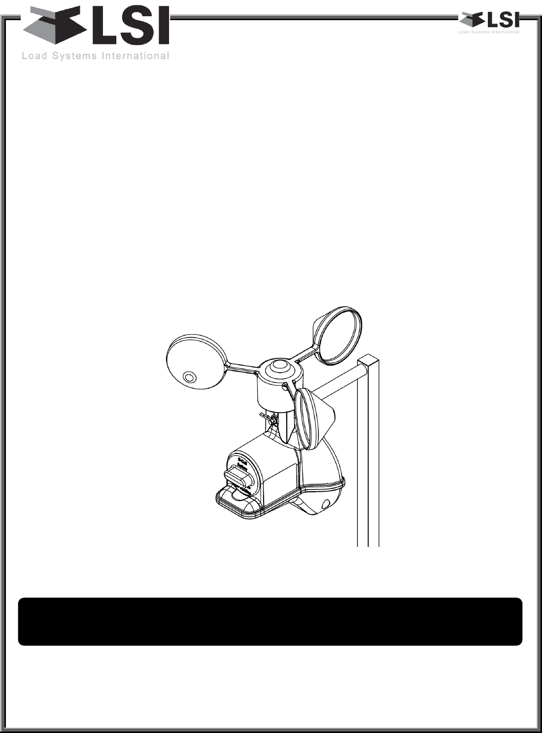
GS025
Radio Anemometer
I
In
ns
st
ta
al
ll
le
er
r
a
an
nd
d
u
us
se
er
r
g
gu
ui
id
de
e
WARNING
! Carefully read and understand this manual and the
GS320/GS550/GS820 Installer and User’s manual before proceeding.
Manual before proceeding.

GM025_ENG_rev.docx www.loadsystems.com 2
IMPORTANT!
Refer to the “GS320/GS550/GS820 Display & GS Series
Sensors - Installer and User’s Manual” for complete information about
installation, operation, maintenance, certification and warranty.
GM025_ENG_rev.docx www.loadsystems.com 3
Read and understand the following:
For your safety and that of the people that come into contact with LSI products, understand
the significance of the instructions included in this guide, respect all laws and regulations
and comply with applicable standards.
Pay particular attention to text boxes and the following words:
Warning: this denotes an instruction that if not complied with may lead to serious injury or
death.
Important: this denotes an instruction that if not complied with may lead to product
performance issues.
1. Overview ........................................................................................................................................ 4
2. Location ......................................................................................................................................... 4
3. Installation ..................................................................................................................................... 4
4. Operation ...................................................................................................................................... 5
5. Security .......................................................................................................................................... 5
6. Battery replacement ...................................................................................................................... 5
7. Replacement parts ........................................................................................................................ 5
Table of contents
WARNING!
Installation must be made in compliance with
LSI
instructions and using
LSI
supplied components only. Failure to install all parts, or replacing parts or
components with parts or components not supplied by
LSI
, may lead to system
failure, serious injury or death.
IMPORTANT!
WARNING!
BEFORE PROCEEDING
GM025_ENG_rev.docx www.loadsystems.com 4
1. Overview
The GS025 is a magnetically encoded
radio anemometer. The wind speed
values are computed from pulses of
magnets inserted in the rotor. This means
that this anemometer has no adjustment
and thus never needs to be calibrated.
Its battery powered electronics gives it an
extended autonomy and the radio
connection allows it to be installed in
remote locations with difficult access.
Both the battery and rotor can be field
serviced without the need for tools.
2. Location
The anemometer location should be on
the same side of the boom as the cabin
mounted display, perpendicular to the
boom, and at the highest point possible.
The wind speed sensor must pivot freely
on the mounting mast at all boom angles.
The wind cups must be fully exposed to
the wind and spin freely at all boom
angles.
There should be a clear and unobstructed
line of sight between the anemometer
sensor and the cabin mounted display
unit.
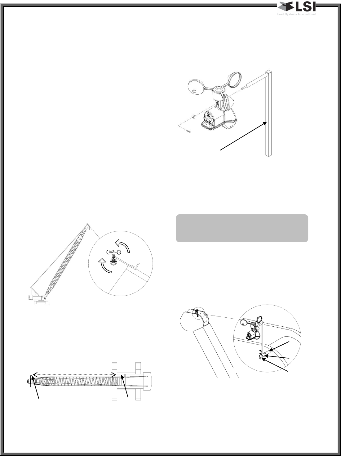
3. Installation
Weld or screw the mast to the boom at
the selected position.
Note: An iron angle can be used to extend
the reach of the mast to clear the boom
tip.
The U-bolt can be used when retrofitting
the GS025 on an already installed GS020
rod (previous generation anemometer).
Make sure the U-bolt is fully tightened
and add the washer and cotter pin at the
rod tip.
Once the mast is secured in place the
radio anemometer can be inserted on the
pivot and secured in place by the washer
and hairpin.
IMPORTANT!
Do not weld in
proximity to
LSI
sensor/transmitters.
Mast
GS020 Rod
U-Bolt
Washer &
cotter pin
Cab
Anemometer
Line of sight
GM025_ENG_rev.docx www.loadsystems.com 5
4. Operation
The radio anemometer is fully functional.
It does not need to be calibrated or
adjusted.
Refer to the GS320/GS550/GS820 manual
for how to add this sensor to the sensor
list to be displayed.
5. Security
The radio anemometer is equipped with a
failsafe power system allowing it to
communicate instantaneously an alarm
via radio signals if the battery of the
power circuit is rendered inoperative.
In the advent of a radio failure, the radio
communication protocol will generate an
alarm within 5 minutes of the loss of
signal.
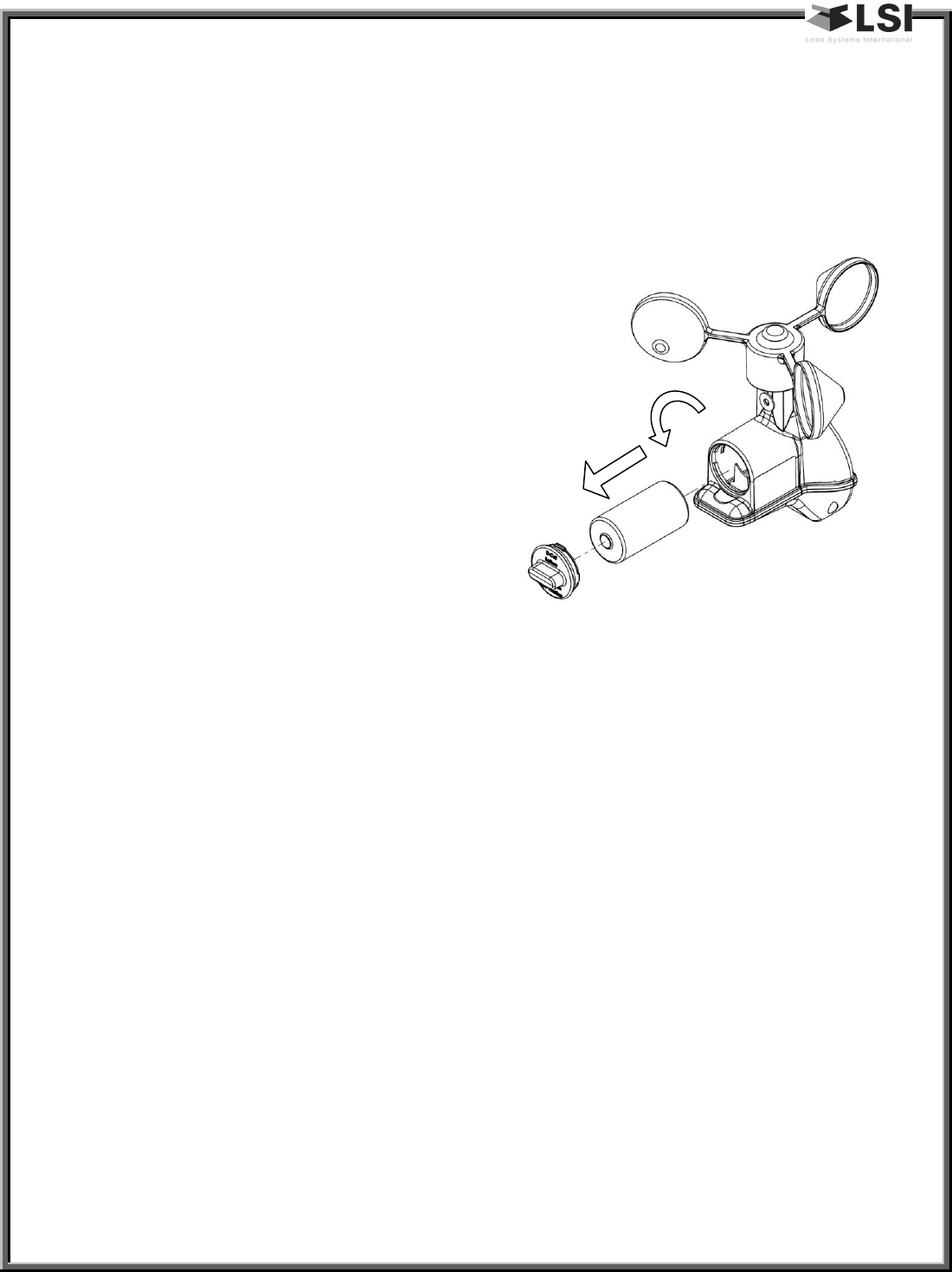
6. Battery replacement
After a period of about 4 years, the
battery may need to be replaced. To
ensure the same performance as the
supplied battery, replace with:
3.6V lithium D cell
If this type of battery is not available, this
type can be used but with a reduced life:
1.5V Alkaline D cell
To replace a battery, turn the battery
cover ¼ turn counter clock wise and
remove, the battery can then be changed
and reclose the battery cover by turning ¼
turn clock wise.
7. Replacement parts
PD058-A: rotor assembly

GM025_ENG_rev.docx www.loadsystems.com 6
8. FCC and IC – Instructions to
the User
This equipment has been tested and
found to comply with the limits for a class
B digital device, pursuant to part 15 of the
FCC Rules. These limits are designed to
provide reasonable protection against
harmful interference in a residential
installation. This equipment generates,
uses, and can radiate radiofrequency
energy and if not installed and used in
accordance with the instructions, may
cause harmful interference to radio
communications. However, there is no
guarantee that interference will not occur
in a particular installation. If this
equipment does cause harmful
interference to radio or television
reception, which can be determined by
turning the equipment off and on, the
user is encouraged to try to correct the
interference by one or more of the
following measures:
• Reorient or relocate the receiving
antenna.
• Increase the separation between the
equipment and receiver.
• Connect the equipment into an outlet
on a circuit different from that to which
the receiver is connected.
• Consult the dealer or an experienced
radio/TV technician for help.
In order to maintain compliance with FCC
regulations, shielded cables must be used
with this equipment. Operation with non-
approved equipment or unshielded cables
is likely to result in interference to radio
and TV reception.
IMPORTANT!
Changes or modifications to this
equipment not expressly approved by
the party responsible for compliance
could void the user’s authority to
operate the equipment.
FCC ID: QVBGS002 IC: 7076A-ICGS002
RF Exposure Warning:
This product complies with FCC/IC
radiation exposure limits set forth for an
uncontrolled environment. To comply
with RF exposure requirements, the unit
must be installed and operated with 20
cm (8 in.) or more between the product
and your body. This product may not be
collocated or operated in conjunction
with any other antenna or transmitter.
This device complies with Industry Canada
licence-exempt RSS standard(s).
Operation is subject to the following two
conditions: (1) this device may not cause
interference, and (2) this device must
accept any interference, including
interference that may cause undesired
operation of the device.
This Class A digital apparatus complies
with Canadian ICES-003.
GM025_ENG_rev.docx www.loadsystems.com 7
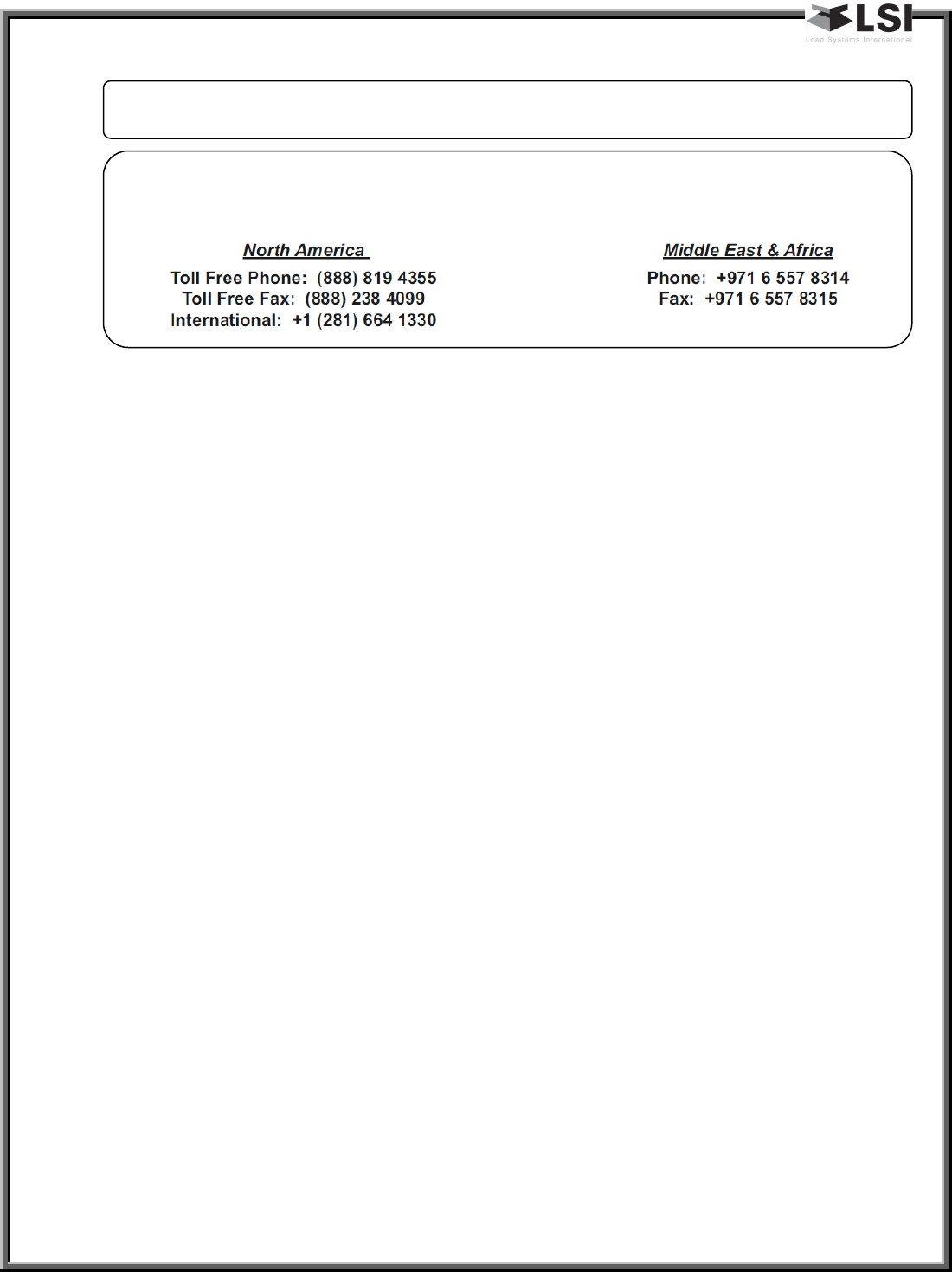
LSI Contact Information
Technical support :
LSI Technical Support is available 24 hours a day, 7 days a week from our Houston and Dubai locations.
Please direct all technical support questions to either of these locations or contact us via email:
techsupport@loadsystems.com