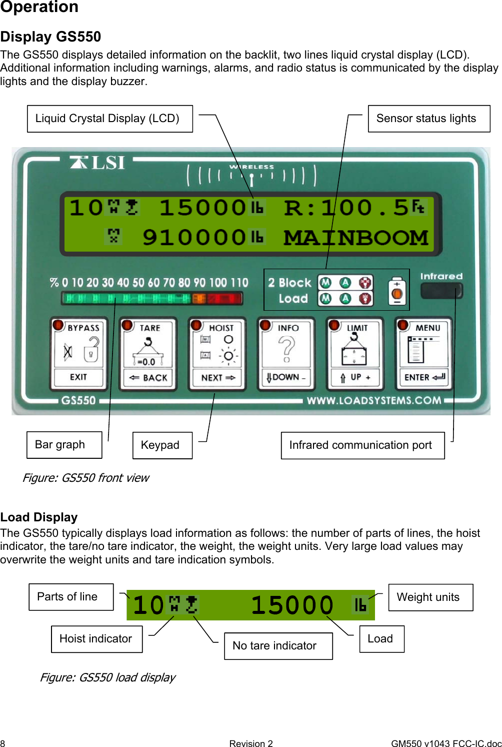
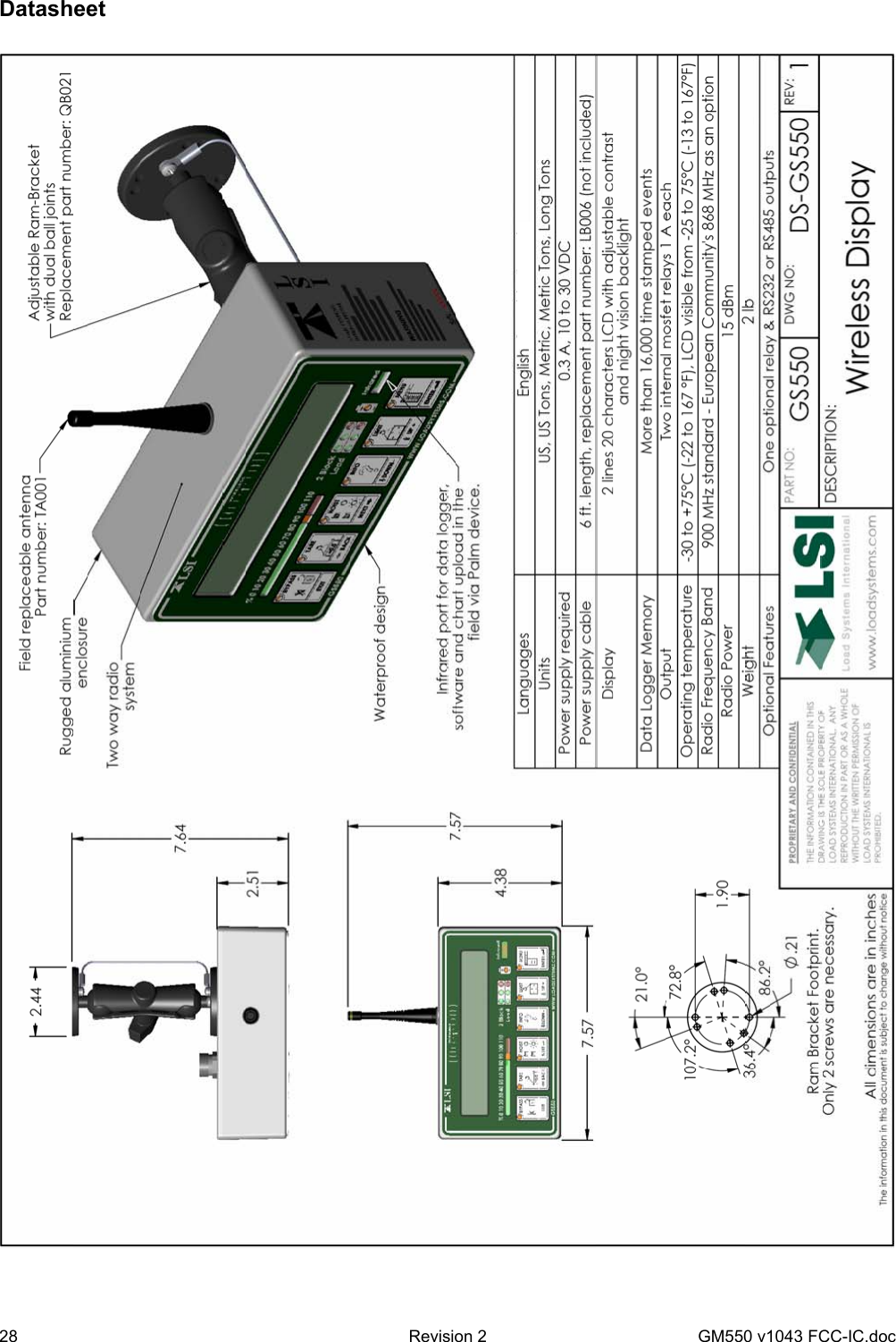
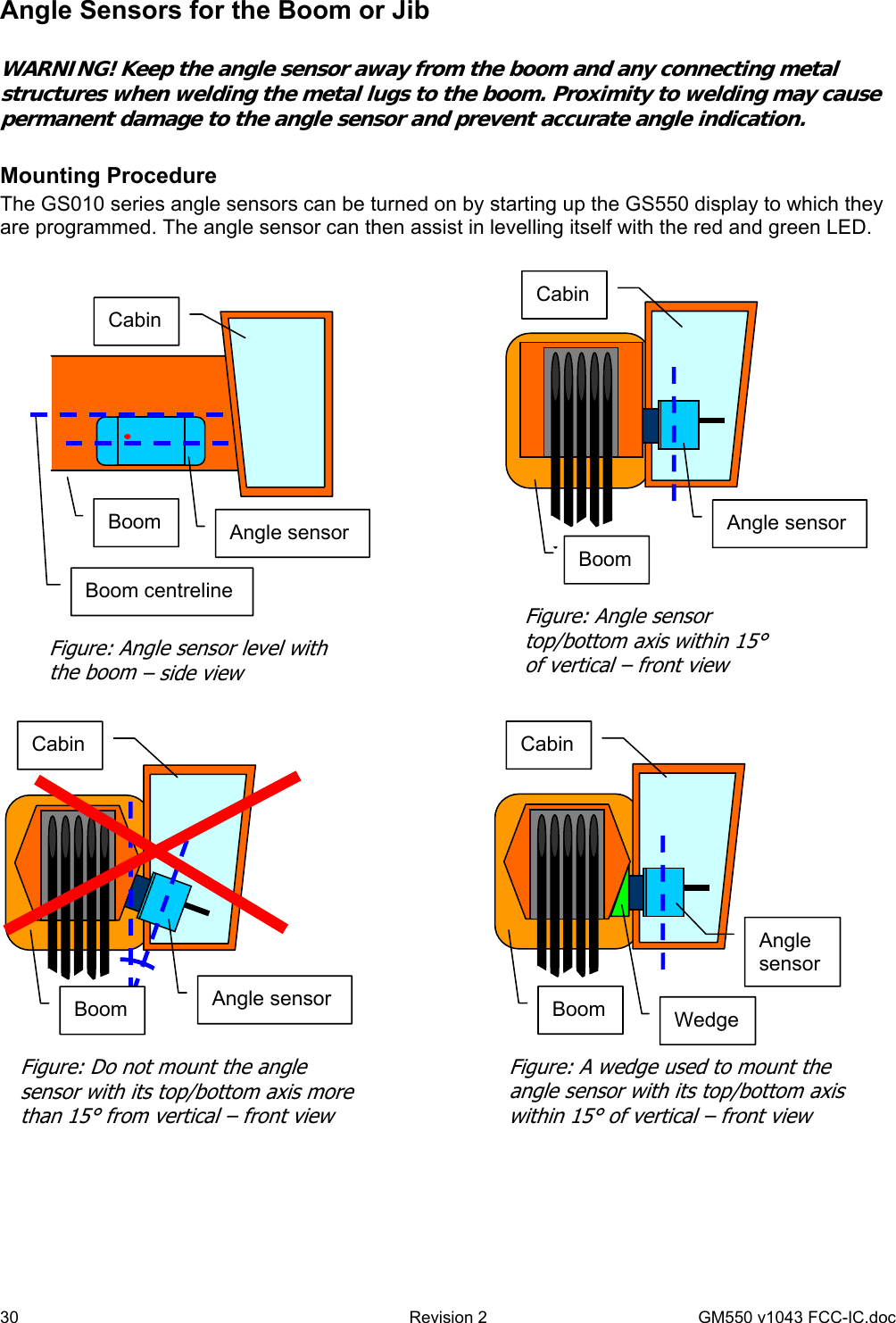
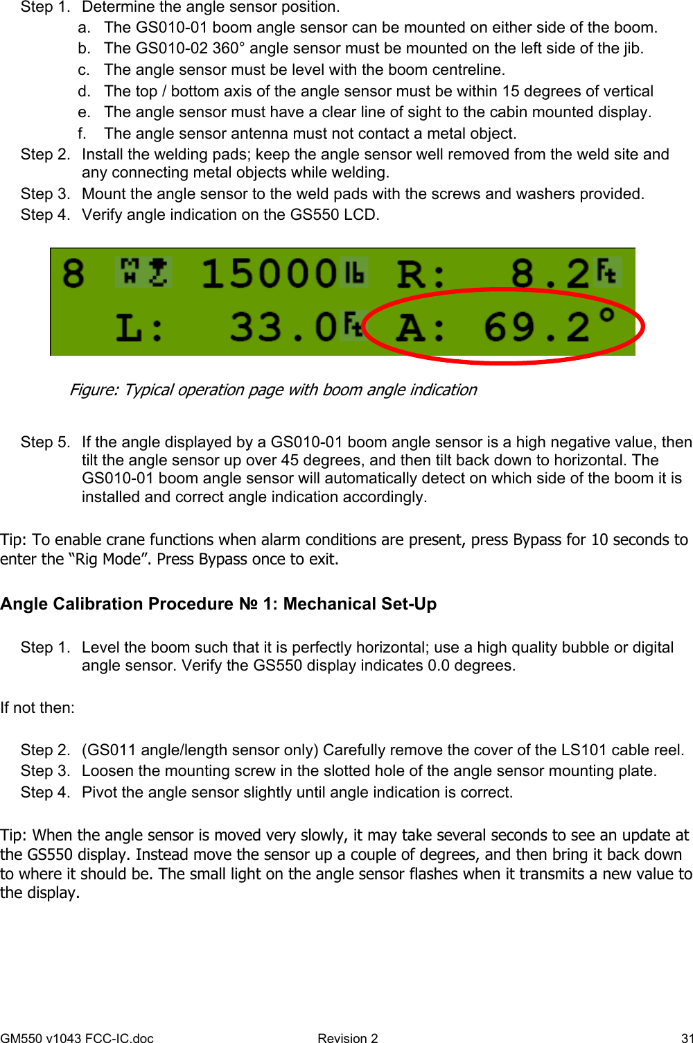
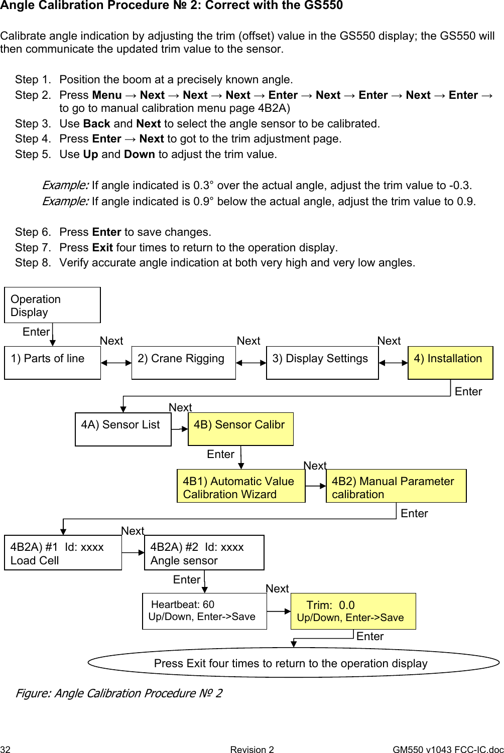
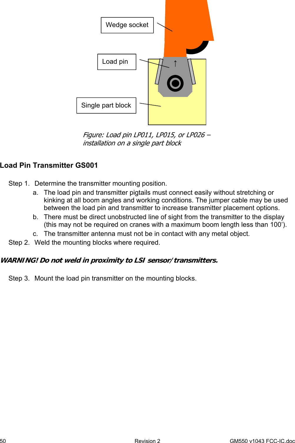
Load Systems GS050 Spread Spectrum Transmitter User Manual GM550 v1043 FCC IC
Load Systems International, Inc. Spread Spectrum Transmitter GM550 v1043 FCC IC
UserManual.wiki
>
Load Systems
>
GS050 User Manual
User manual
Navigation menu
Upload a User Manual
Namespaces
Wiki Guide
HTML
PDF
Info
Views
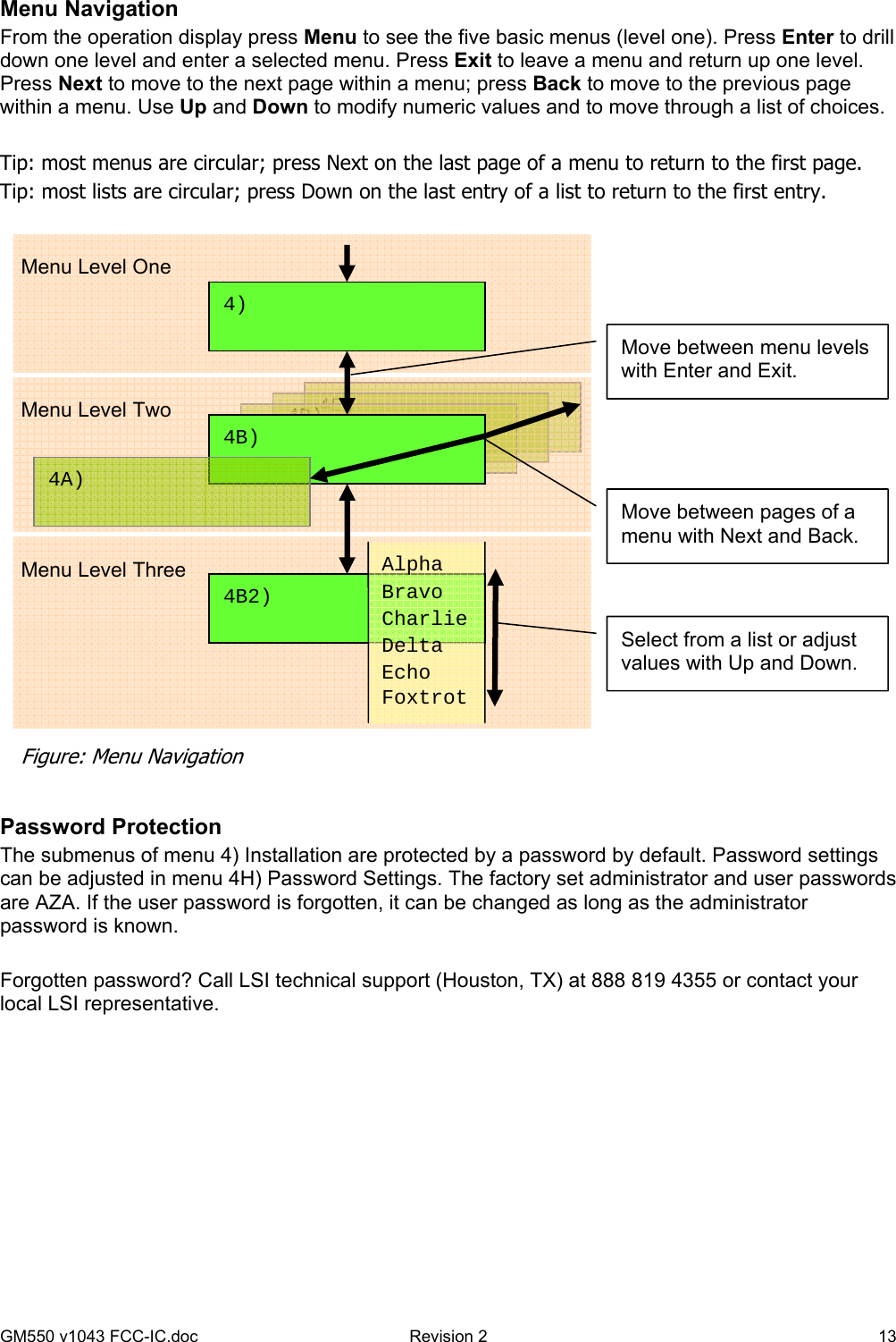
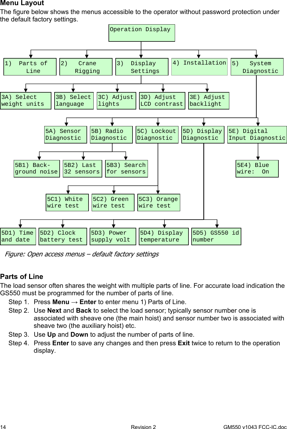
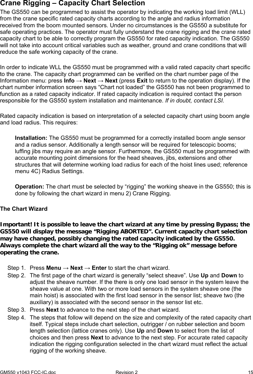
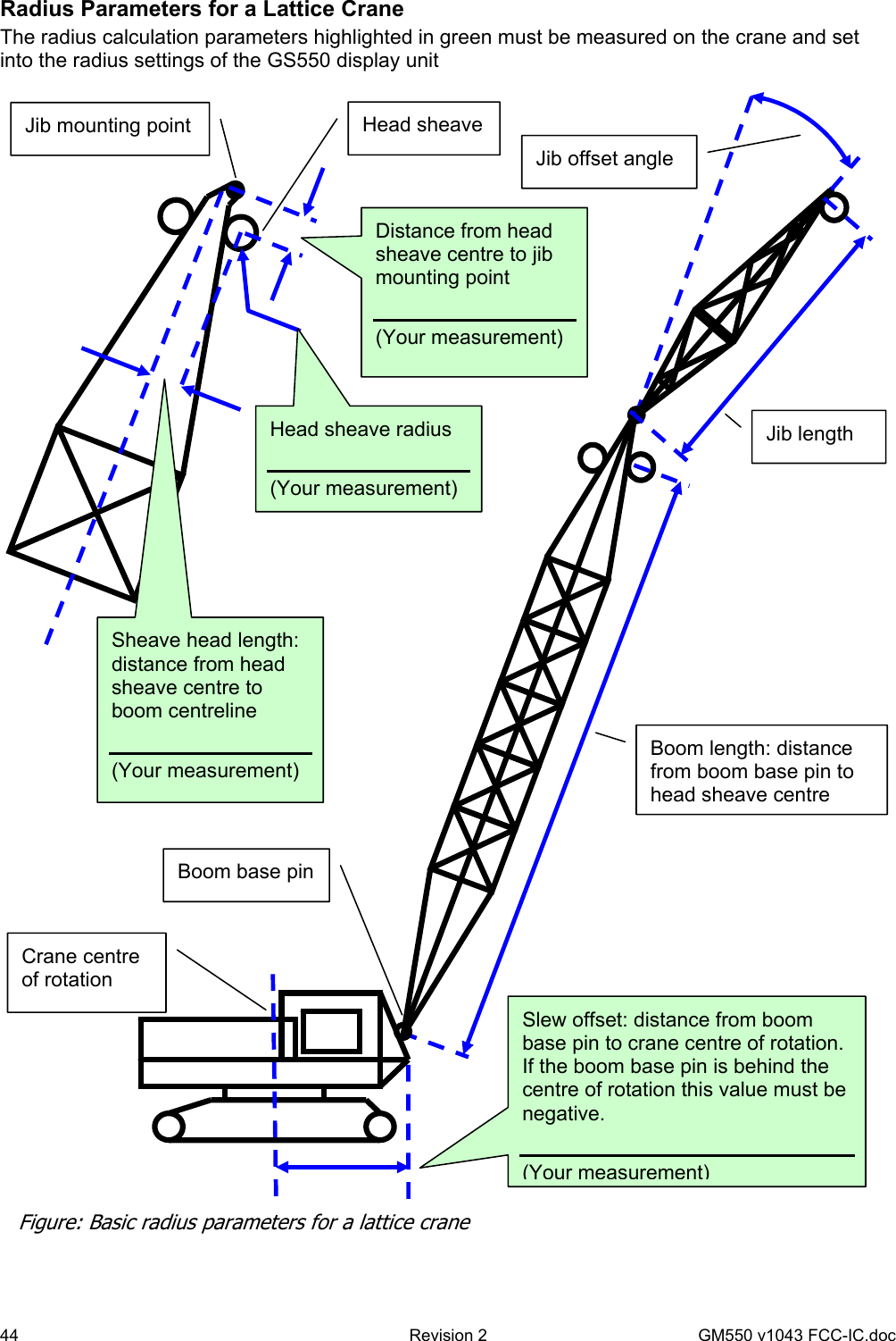
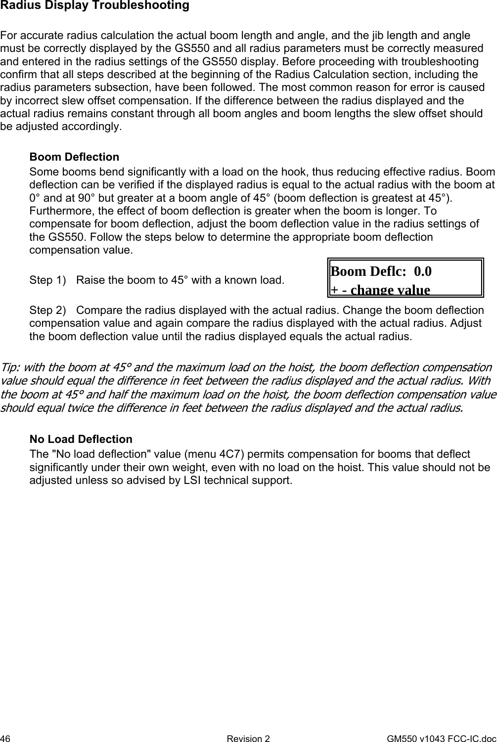
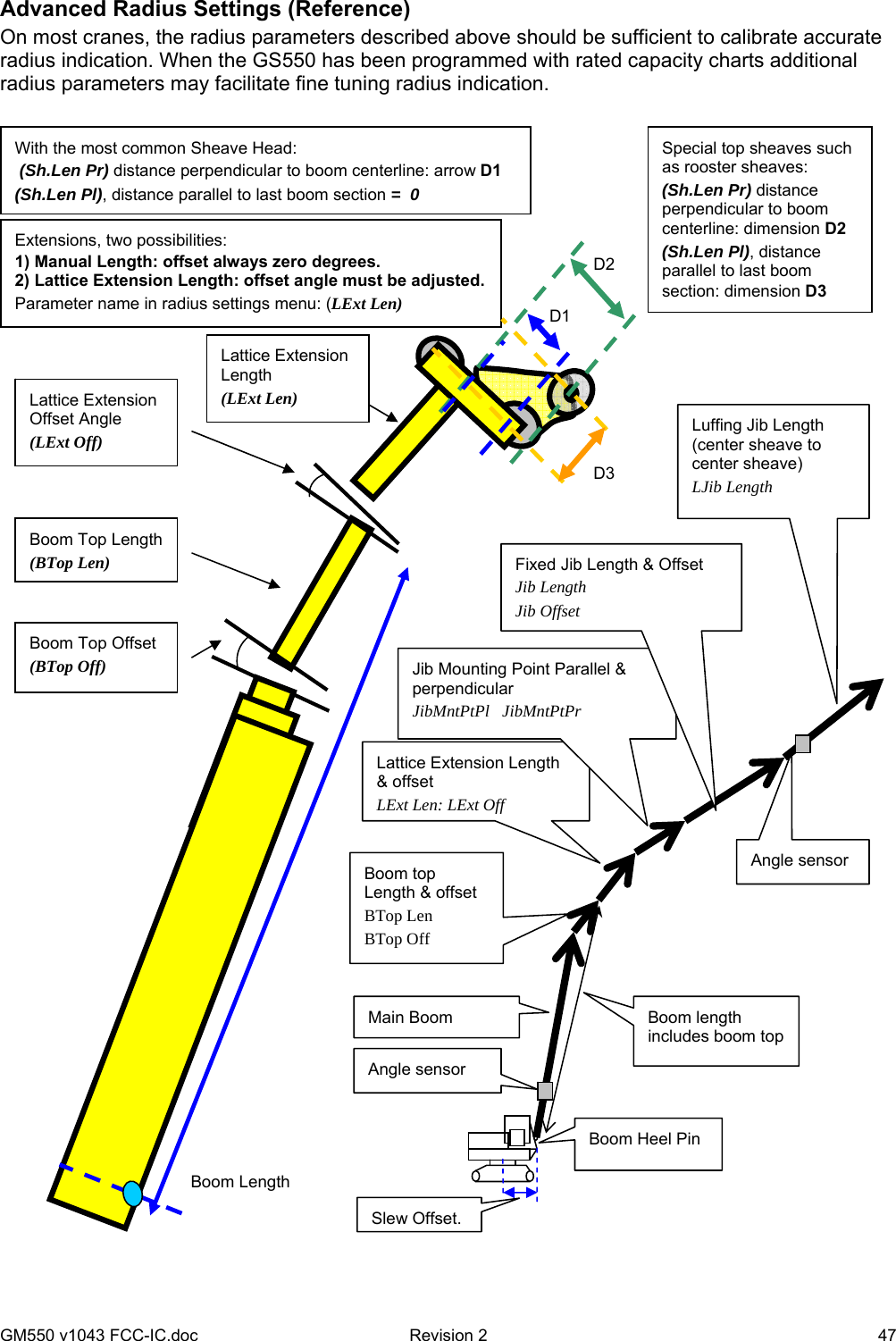
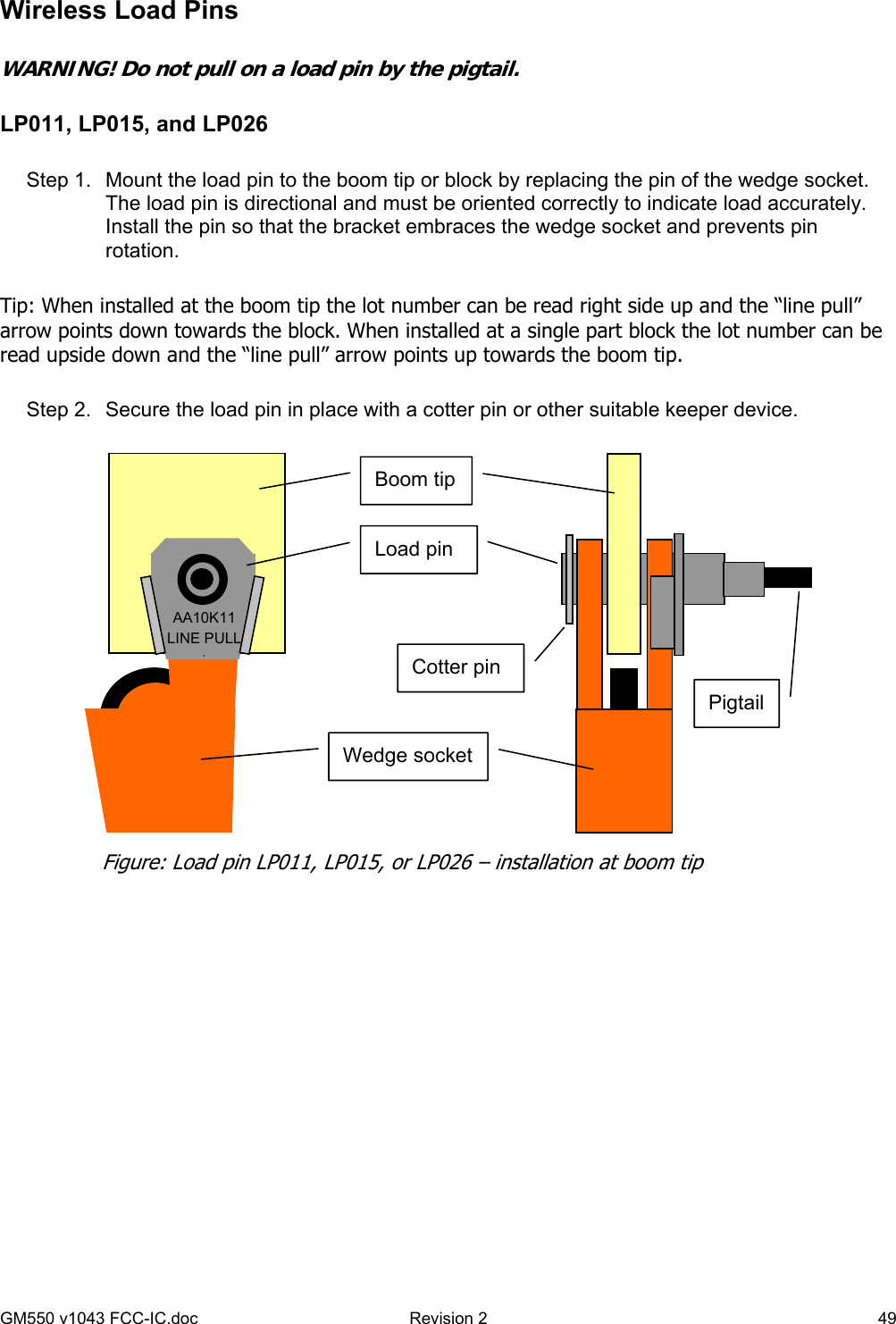
User Manual
Discussion / Help
Navigation