Load Systems GS820 Generic Display User Manual GM820 rev20090409 Layout 1
Load Systems International, Inc. Generic Display GM820 rev20090409 Layout 1
Contents
- 1. Users Manual Part One
- 2. Users Manual Part Two
Users Manual Part Two
ISTALLATIO
ISTALLATIO 29
29
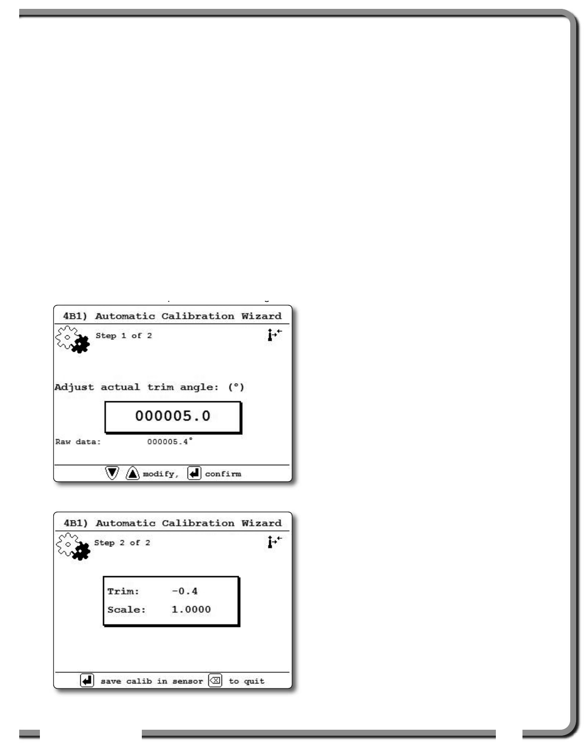
2.12c List and Trim Angle
Calibration Procedure
Calibrate angle indication by adjusting the offset
values for list and trim in the GS820 display; the
GS820 will then communicate the updated offset
values to the sensor.
1. Install the sensor at a precisely known list
and trim angle.
2. Go to menu 4) INSTALLATION and select 4B)
SENSOR CALIBRATION.
3. Enter the user password and press Enter.
4. Select 4B1) AUTOMATIC CALIBRATION WIZARD.
5. Use Up and Down to select the trim (or list)
sensor.
6. Press Enter to go to the first step of the calibration
wizard; note the uncorrected angle indicated.
7. Use Up and Down to adjust the angle value
indicated until it is equal to the known angle.
7. Note the trim and scale values.
8. Press Enter to save and communicate changes
to the sensor.
9. Repeat steps 4 through 8 for the list angle.
10.Press Exit to return to the operation display.
12.Verify accurate list and trim angle indication.
Figure: Trim Angle calibration, adjust the angle
Figure: Trim Angle calibration, trim and scale values
30
30 The GS820 System
The GS820 System
2.13
2.13 Rope payout
Rope payout
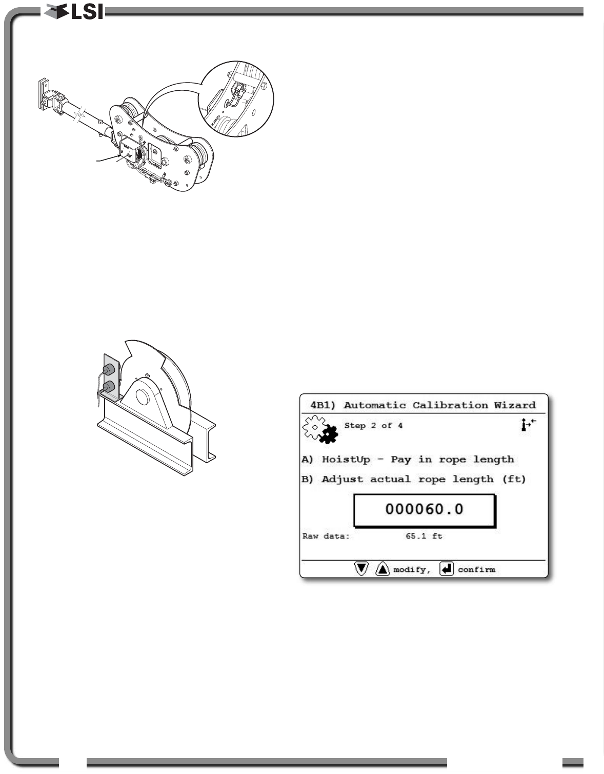
Typically the rope payout sensor is factory installed
on the line riding tensiometer load sensor (figure
above). Alternatively the rope payout sensor may
be installed on an appropriate sheave (figure
below). Power supply must be provided to the rope
payout sensor. A GS820 display can then be
programmed to communicate with the sensor and
to indicate rope payout (length) and rope speed.
Zero the rope payout using the Tare menu before
calibration.
2.13a Rope Payout Calibration
Procedure № 1: Mechanical
Set-Up
1. Hoist up to reel in the wire rope fully.
2. Install the rope payout system.
3. Zero the rope payout length in the Tare menu
4. Hoist down to pay out a known length of wire
rope (for example: 20 feet).
5. Verify the rope payout indicated matches the
actual length of wire rope paid out. If not then
follow Rope Payout Calibration Procedure № 2.
2.13b Rope Payout Calibration
Procedure № 2: Correct with
the GS820
If rope payout indicated does not match actual rope
payout, and if it is not possible to easily correct by
following Rope Payout Calibration Procedure № 1,
then follow this procedure. This procedure requires
hoisting up to fully reel in the wire rope, and then
hoisting down to pay out a known length of wire
rope. For accurate calibration the “known length”
paid out must be accurately measured.
1. Go to menu 4) INSTALLATION and select 4B)
SENSOR CALIBRATION.
2. Enter the user password and press Enter.
3. Select 4B1) AUTOMATIC CALIBRATION WIZARD.
4. Use Up and Down to select the rope payout
sensor, and then press Enter to confirm
communication with the sensor is established.
5. Note the units that will be used during the
calibration wizard, and then press Enter.
6. Hoist up (pay in) the wire rope, use Up and
Down to adjust the actual wire rope payout
length and then press Enter.
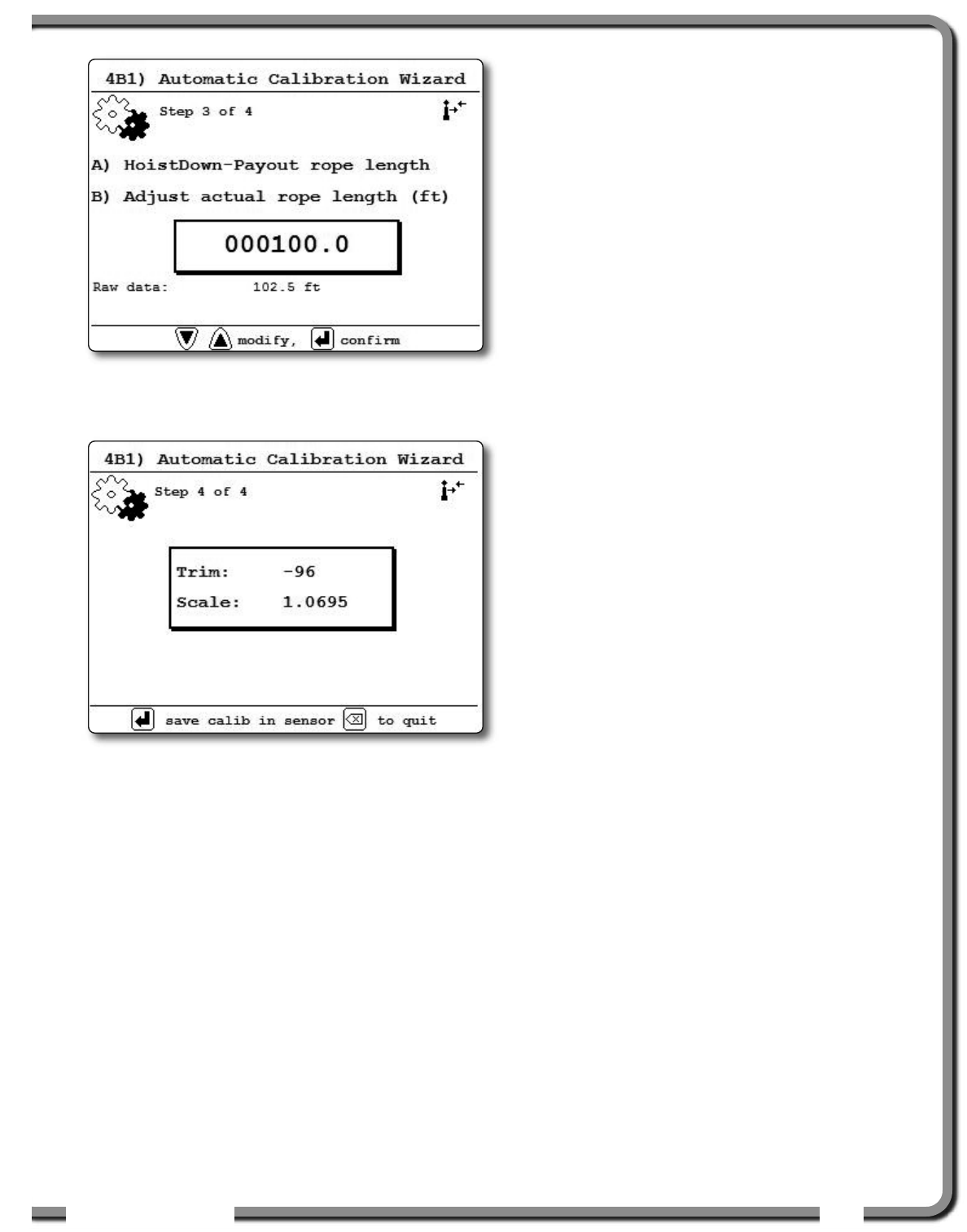
7. Hoist down (payout) the wire rope, use Up and
Down to adjust the actual wire rope payout
length and then press Enter.
Rope payout
sensor
Figure: Rope payout on a line riding tensiometer
Figure: Alternative installation of a rope payout
Figure: Rope payout calibration, adjust the actual rope length
ISTALLATIO
ISTALLATIO 31
31
8. Note the new trim and scale values.
9. Press Enter to save and send the new
calibration to the rope payout sensor.
10.Press Exit to return to the operation display.
2.13c Rope Payout Limits
The minimum and maximum rope payout (length)
limits and the maximum rope speed limit can be
adjusted in the display in the limit menu. The
maximum rope payout limit can be programmed to
trigger lockout when exceeded, see menu 4G)
LOCKOUT SETTINGS. The minimum rope payout limit
and the maximum rope speed limit will trigger an
alarm when exceeded. The default limit for
maximum rope payout is 300 feet; the default
minimum limit is -300 feet. The default limit for
maximum rope speed is 15.0 feet per second.
2.13d Electrical connections
Voltage: 9 to 30 Volts DC, about 0.3 Amp
Red wire: positive voltage
Blue wire: negative or ground
Two types of connections are recommended;
1) Always powered up
2) Powered-up at the same source as the
GS820 display unit
Figure: Rope payout calibration, adjust the actual rope length
Figure: Rope payout calibration, trim and scale values
32
32 The GS820 System
The GS820 System
2.14
2.14 Data Logger
Data Logger
The GS820 includes a data logger that records all
significant events including actual sensor values and
a date and time stamp. The data logger memory can
hold over 32 000 records, this is equivalent to
several days or several years of operation
depending on the recording mode selected and
machine use. The data can be extracted using a
USB mass storage device (USB key) and then
transferred to a personal computer for analysis.
2.14a Recording Modes
Adjust the data logger recording mode as required:
1. Go to menu 4) and select 4F) DATA LOGGER.
2. Enter the user password and press Enter.
3. Use Up and Down to select the data logger
recording mode and press Enter.
Automatic modes only: select the record added
below the recording mode (interval, variation or
threshold), press Enter and adjust the value
using Up and Down, then press Enter.
4. Press Enter to save any changes.
5. Press Exit to return to the operation display or
press Down to adjust the data logger date and
time (see Date and Time sub-section).
Recording Modes description:
Alarm only. Record alarms only. All the other
data logger modes also record alarms.
Automatic recording. A record is added at a
specified interval. When the automatic
recording data logger mode is selected on
menu 4F) 1) (see step 3 above) select 1A)
MINUTES, press Enter and then use Up and
Down to adjust the record interval in minutes.
Automatic variation. A record is added when
load increases by more than the operator
adjusted percentage. When the automatic
variation data logger mode is selected on menu
4F) 1) (see step 3 above) select 1A) VARIATION
(%), press Enter and then use Up and Down to
adjust the variation threshold.
Automatic peak. In the automatic peak mode
the data logger analyzes the measured weight
and records the peak value only. One threshold
per load cell must be adjusted. When the weight
drops by more than the peak threshold the peak
weight is recorded. Only one event is recorded
for each pick when the threshold is adjusted
correctly. When the automatic peak data logger
mode is selected on menu 4F) 1) (see step 3
above) select 1A) THRESHOLD №1, press Enter
and then use Up and Down to adjust the peak
threshold for the first load cell. Press Down to
repeat for the second load cell etc. Up to four
load cells can be programmed for automatic
peak data logging.
User input. The status of all sensors is
recorded on demand. A normally open push
button must be installed on a digital input to the
GS820 through a pre-determined wire of the
power supply and lockout cable.
All data. All communications between a display
and its sensors are recorded.
2.14b Date and Time
Adjust the data logger date and time as required:
1. Go to menu 4) and select 4F) DATA LOGGER.
2. Enter the user password and press Enter.
3. Select 2) DATE and press Enter.
4. The digits of the year should be flashing: use
Up and Down to adjust the year and press
Next.
5. Use Up and Down to adjust the month and
press Next.
6. Use Up and Down to adjust the day and press
Enter to confirm.
7. Select 3) TIME and press Enter to adjust the time.
8. The hour should be flashing: use Up and Down
to adjust the hour from 00 (midnight) to 23 (11 pm).
9. Press Next to adjust the minute.
10.Use Up and Down to adjust the minute and
press Next.
11. Use Up and Down to adjust the second and
press Enter to save any changes.
12.Press Exit to return to the operation display.
IMPORTANT!
Wind speed: the data logger
recording mode must be set to automatic
recording to log the data required by the wind
speed report feature of the Data Logger
Viewer software.
Note: all alerts are recorded by the data logger
regardless of the mode selected.
!
!
ISTALLATIO
ISTALLATIO 33
33
2.15
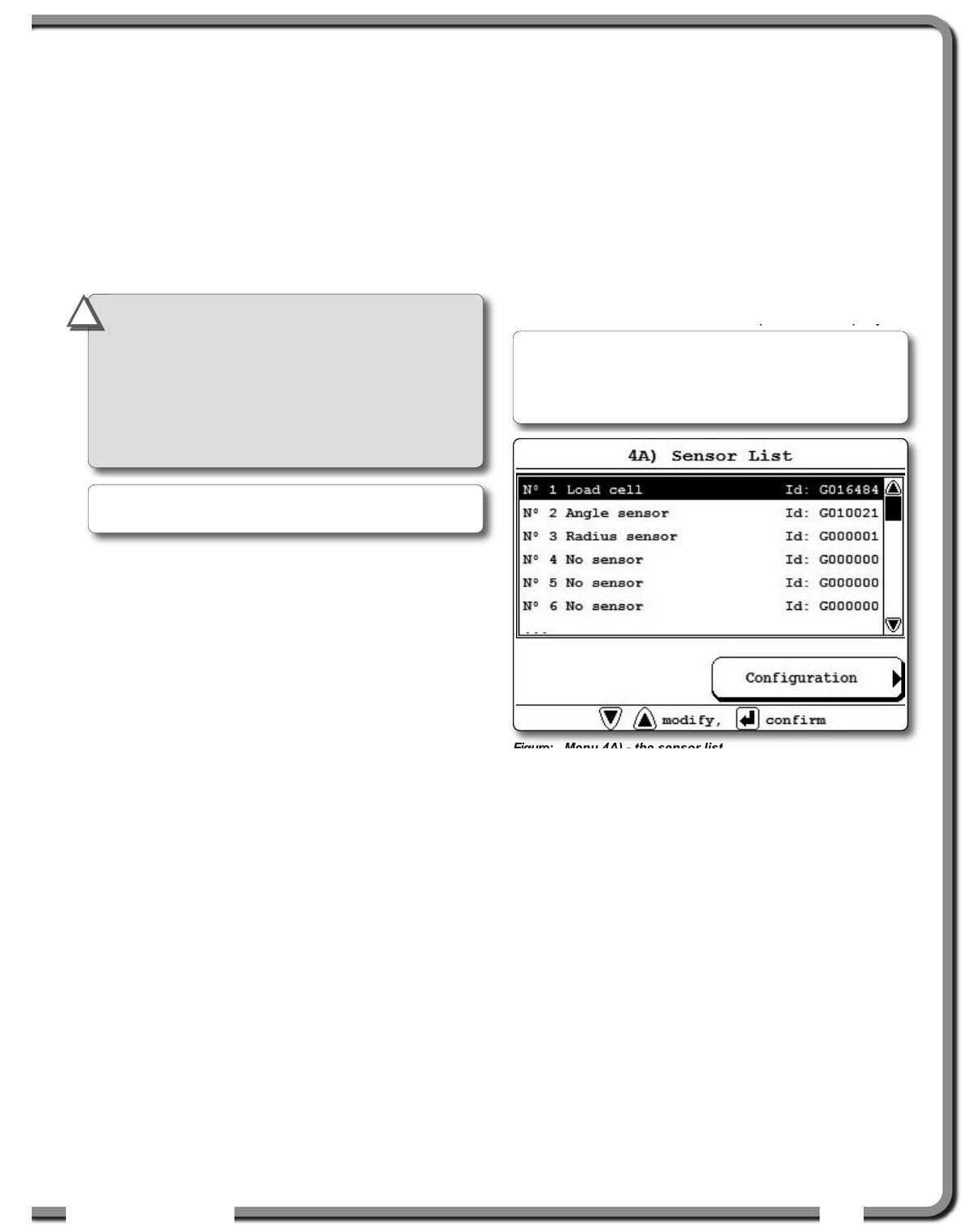
2.15 Sensor List
Sensor List
All sensors in the GS820 system are programmed
in the sensor list. The GS820 uses information from
all sensors in the sensor list. Conversely the
GS820 will not use or display information from
sensors that are not programmed to the sensor list.
If a sensor is removed from the crane then it must
be removed from the sensor list. If a sensor is
replaced the sensor list must be updated with the
new ID number.
2.15a How to Add a Sensor to the
GS820
1. Determine the radio identification number (ID) of
the sensor to be added. This number between
10000 and 99999 is engraved on the sensor.
2. Go to menu 4A).
3. Enter the user password and press Enter.
4. Advance to the next empty sensor position in
the sensor list “NO SENSOR”. Up to 32 sensors
may be added to the sensor list. Press Enter.
5. Use Up and Down to select the sensor type
and press Enter.
6. Use Up and Down to program the sensor ID
and press Enter.
7. Press Enter to save any changes made to the
sensor list.
8. Press Exit to return to the operation display.
2.15b How to Remove a Sensor from
the GS820
1. Determine the sensor to be removed. If more than
one sensor of the same type has been added to
the sensor list then determine the radio
identification number (ID) of the sensor to be
removed before proceeding. This number between
10000 and 99999 is engraved on the sensor.
2. Go to menu 4A).
3. Enter the user password and press Enter.
4. Select the sensor to be removed and press
Enter to modify.
5. Use Up and Down to select “No sensor”. This
will remove the sensor from the sensor list but
retain the sensor ID.
6. Press Enter to save any changes made to the
sensor list.
7. Press Exit to return to the operation display.
Figure: Menu 4A) - the sensor list
2.16
2.16 Network Options
Network Options
2.16a Listen Only Mode
When the GS820 is started it normally wakes up
the sensors in the sensor list and takes control of
them. The last display powered on that is
programmed for a sensor becomes that sensor’s
network controller. This means that if a second
display is programmed for a sensor, it will take
control of it; the sensor will no longer acknowledge
communication from the first display. Occasionally
it may be useful to monitor an installed system from
a remote display without disrupting the existing
network. The GS820 can be programmed to
operate in “listening mode”. In this mode the
GS820 will display information from programmed
sensors without becoming the network controller.
IMPORTANT!
Information displayed from
load, angle and boom length sensors that are
not correctly installed will not be accurate.
IMPORTANT!
Rated capacity, radius, and
tip height based on information from angle
and boom length sensors that are not
correctly installed will not be accurate.
Note: To ensure communication, sensors must be
at least six feet from the GS820 display.
!
!
Note: Press Next and Back simultaneously to
remove the sensor from the sensor list. The ID
number will revert to 0, and the sensor type will
revert to “NOSENSOR”.
34
34 The GS820 System
The GS820 System
Program the listen only mode
1. Go to menu 4) and select 4I) NETWORK OPTIONS.
2. Enter the user password and press Enter.
3. Select 4I1) NETWORK CONTROL).
4. Press Enter to modify “DISPLAY MODE” and use
Up and Down to switch between “NETWORK
CONTROLLER” and “LISTEN ONLY” modes.
5. Press Enter to save any change.
6. Press Exit to return to the operation display.
When a display is adjusted to “listen only mode”
the following message flashes three times
during the start-up routine: “THE DISPLAY IS IN
LISTEN ONLY MODE”.
2.16b Repeater
Communication between a GS820 and a programmed
sensor can be routed through a different programmed
sensor (repeater). This can be done either to extend
the range of the network or to assist communication
around a large radio obstacle. The battery life of the
sensor repeated (source) will be reduced by about a
year*. The battery life of the sensor repeater will be
reduced to 35 days**. This function should not be used
where it is not required.
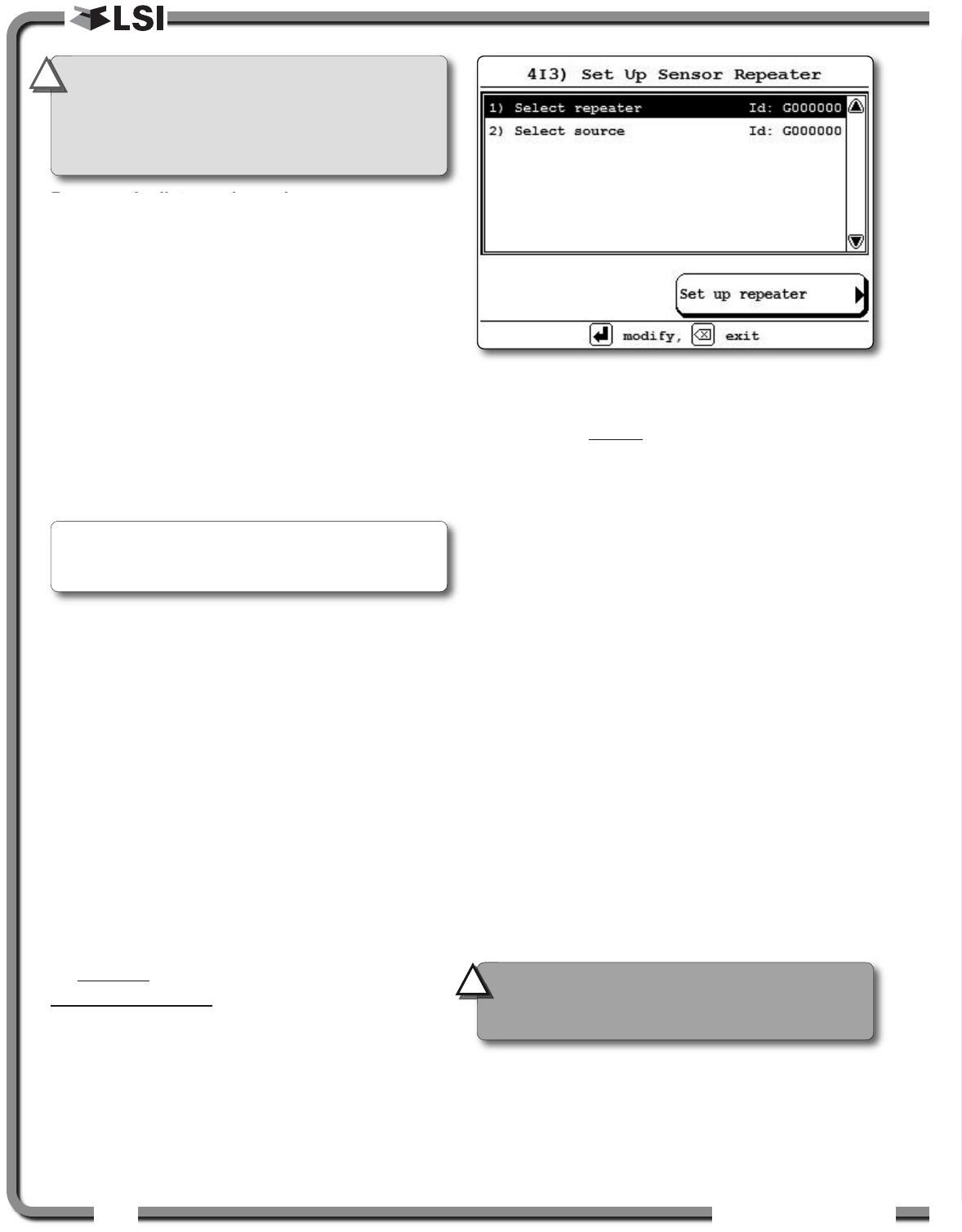
Program a sensor repeater
1. In menu 4I), select 4I3) SET UPSENSOR REPEATOR.
2. Select 1) SELECT REPEATER, press Enter to
modify and use Up and Down to program the
radio ID number of the sensor that will be the
repeater and press Enter to confirm.
3. Select 2) SELECT SOURCE, press Enter and
program the radio ID number of the sensor that
will be the source and press Enter.
4. Press “SET UP REPEATER” to save the new
network path. The following messages will be
displayed briefly:
“PARAMETERS SAVED CORRECTLY”
“COMMUNICATING WITH REMOTE SENSOR”
“CONFIGURATION SAVED SUCCESSFULLY”
5. Press Exit to return to the operation display.
Clear a sensor repeater
1. In menu 4I), select 4I2) REPEATOR LIST. Menu 4I2
details the last repeater programmed. When no
repeater has been programmed, “NO REPEATER
SET UP” message is displayed.
2. Select a repeater in the list and press “REMOVE
REPEATER” to shut down the repeater
programmed. The following messages will be
displayed briefly:
“REMOVING NETWORK PATH”
“INITIALIZING NETWORK”
3. To shut down additional repeaters repeat step 1
and 2.
4. Press Exit to return to the operation display.
2.16c Wireless Sensor Update
It is possible to send a firmware update to a sensor
using the GS820 (menu 4I4) INSTALL SENSOR
UPDATE). For more information on installing a
sensor update please contact LSI
LSI.
* Repeated (source) battery life estimated for standard
product, using new factory specified batteries
correctly installed, operating 32 hours per week.
Individual results may vary with intensity of use,
environmental conditions and other factors.
** Repeater battery life estimated for standard
product, using new factory specified batteries
correctly installed. Individual results will not vary
with of intensity of use; individual results may vary
with environmental conditions and other factors.
Figure: Program a sensor repeater
IMPORTANT!
Sensors can only have one
network controller at a time. To receive
communication from a sensor without taking
control of that sensor a display must first be
programmed in “listening mode”.
Note: To regain network control of programmed
sensors adjust the GS820 to “NETWORK CONTROLLER”,
shut the display off, and then start it again.
!
!
CAUTION!
Test all system functions after
setting up or removing a repeater. Shut off
and then restart the GS820.
!
!
OPERATIO
OPERATIO 35
35
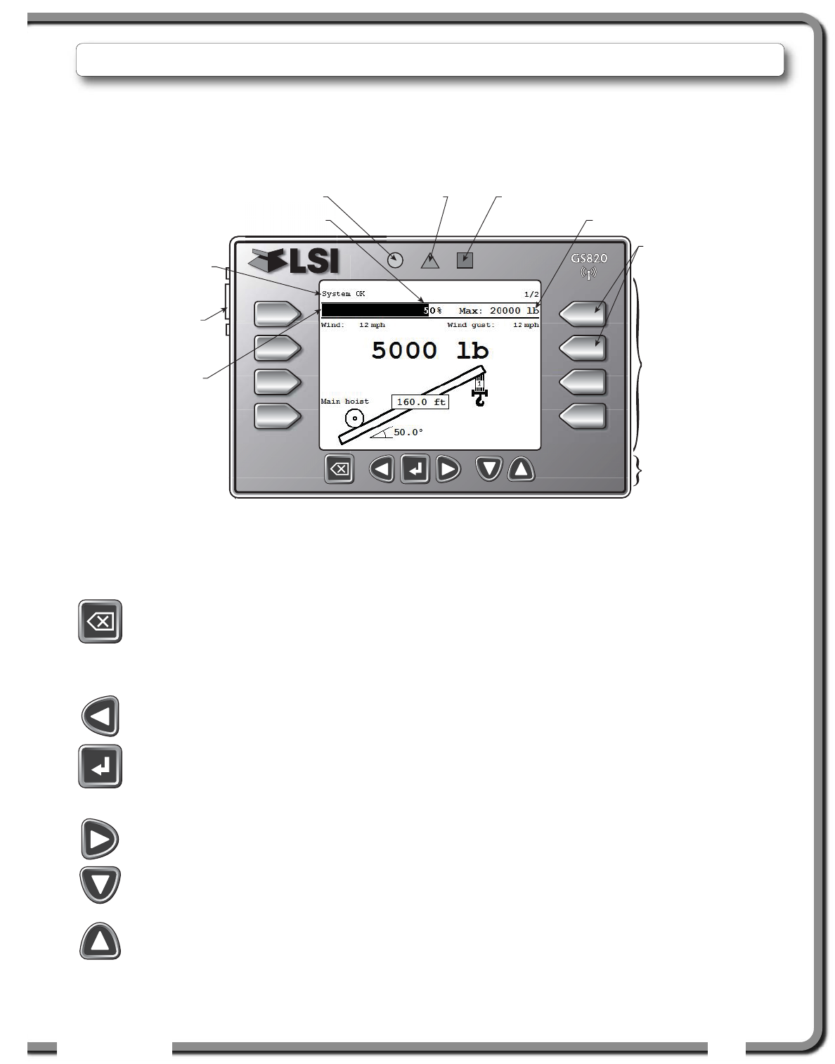
Bypass / Exit
Override lockout for emergency purposes*.
The alarm will remain silent until the next
alarm; lockout will re-engage as soon as the
button is released. / Exit menu.
Back
Move to the previous page/digit.
Menu / Enter
Access the system menus, refer to Menu
System section. / Enter menu, confirm
changes to system settings.
Next
Move to next page/digit.
Down
Modify numeric values and move down
through a list of choices.
Up
Modify numeric values and move up through
a list of choices.
3.4
3.4 Display lights
Display lights
Status light (green)
The status light stays on when the GS820 has a reliable
radio communication link to all programmed sensors.
Warning light (yellow)
The warning light flashes when;
1. the communication with a sensor is not
established (“NORX” apears on LCD);
2. a warning threshold has been reached (typically
90% of the maximum limit);
3. an alarm is bypassed;
4. the sensor battery life drops below 10%. Normally
several weeks of battery life remains from the
moment the low battery message first appears.
A warning message is also generated on the LCD.
Alarm light (red)
The alarm light flashes when a sensor limit is
reached (100% and more). An alarm message is
also generated on the LCD.
3.2
3.2 USB Port
USB Port
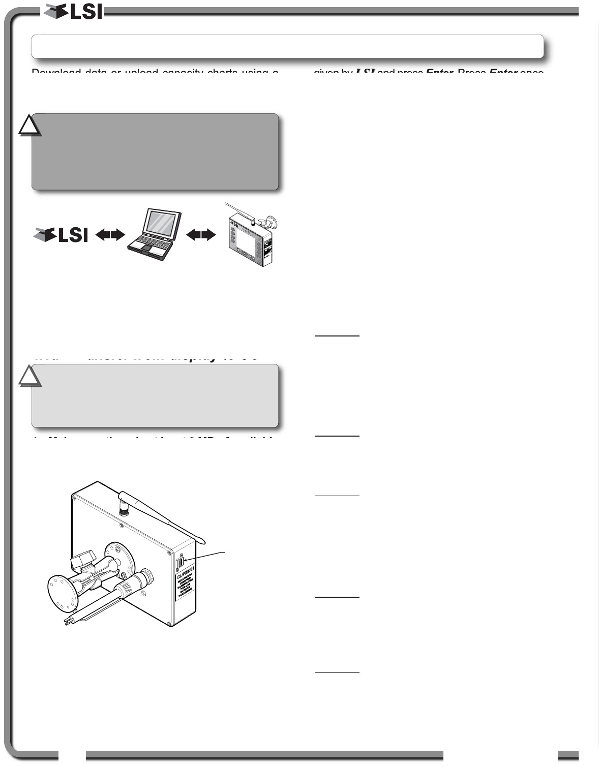
The USB port is used to download data from the
data logger or to upload capacity charts using a
USB mass storage device (USB key).
USB Port
Liquid
Crystal
Display
(LCD)
Keypad
Selection buttons
Press the selection
button to access
line or menu
shown on LCD.
Bar graph
indicates load
on hoist as
percent of limit.
Status light Warning light Alarm light
Percent of limit
Info, alert or
warning
message
Working load limit
3.3
3.3 Keypad
Keypad
The main keypad consists of six buttons used to control, consult, program, and troubleshoot the GS820
display and system. The keypad also includes the selection buttons that allows the user to quickly access
the menus and informations displayed on the LCD.
* This applies only if the GS820 has been correctly
installed to control crane lockout function.
3.1
3.1 Display GS820
Display GS820
The GS820 displays detailed information on the liquid
crystal display (LCD); warnings, alarms, and radio
status is also communicated by the display buzzer.
3.
3. OPERATION
OPERATION
36
36 The GS820 System
The GS820 System
3.5
3.5 Menu System
Menu System
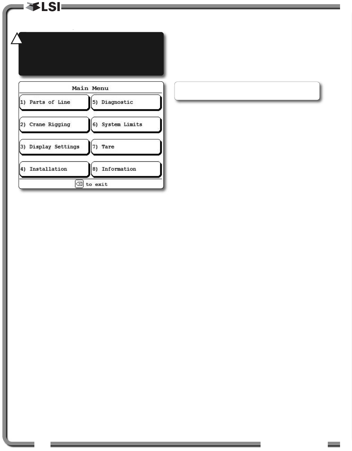
There are eight basic menus (level one) used to
program, consult and control the GS820 system; 1)
PARTS OF LINES; 2) CRANE RIGGING; 3) DISPLAY
SETTINGS; 4) INSTALLATION; 5) SYSTEM DIAGNOSTIC; 6)
SYSTEM LIMITS; 7) TARE; 8) INFORMATION.
The basic menus include nested sub-menus (level
two and three) designed to address specific tasks
including adjusting values, choosing from lists and
following “wizards” through step by step processes.
3.5a Menu Numbers
The basic menus (level one) are numbered one
through eight. Level two menus are lettered
alphabetically. Level three menus are numbered.
Menus can also include numbered lists.
3.5b Menu Navigation
From the operation display press Menu/Enter to
see the eight basic menus (level one). Use the
selection button to select a menu. Press Exit to
leave a menu and return up one level. Press Next
to move to the next page within a menu; press
Back to move to the previous page within a menu.
Use Up and Down to modify numeric values and to
move through a list of choices.
3.5c Password Protection
The submenus of menu 4) INSTALLATION are
protected by a password by default. Password
settings can be adjusted in menu 4H) PASSWORD
SETTINGS. If the user password is forgotten, it can
be changed as long as the administrator password
is known.
3.5d Menu Layout
The menus accessible to the operator without
password protection under the default factory
settings are listed below.
1) PARTS OF LINE
2) CRANE RIGGING
3) DISPLAY SETTINGS
4) INSTALLATION
5) SYSTEM DIAGNOSTIC
5A) SYSTEM SENSORS DIAGNOSTIC
5B) RADIO NETWORK DIAGNOSTIC
5B1) RADIO NETWORK
5B2) LAST SENSORS RECEIVED
5B3) SEARCH FOR SENSORS
5B4) BIT ERROR RATE TEST
5C) LOCKOUT DIAGNOSTIC
5D) DISPLAY DIAGNOSTIC
5E) DIGITAL INPUT DIAGNOSTIC
6) SYSTEM LIMITS
7) TARE
8) INFORMATION
Figure: Basic menus (level one)
Forgotten password? Call LSI
LSI technical support
(Houston, TX) at 888 819 4355.
WARNING!
System limits are not
monitored when the display is in menu
mode. DO NOT operate the crane in menu
mode. DO NOT navigate system menus when
operating the crane.
!
!
OPERATIO
OPERATIO 37
37
3.5e Parts of Line
The load sensor often shares the weight with multiple
parts of line. For accurate load indication the GS820
must be programmed for the number of parts of line.
1. Go to menu 1) PARTS OF LINE.
2. Use Up and Down to select the load sensor;
typically sensor number one is associated with
sheave one (the main hoist) and sensor number
two is associated with sheave two (the auxiliary
hoist) etc. Press Enter to modify.
3. Use Up and Down to adjust the number of parts
of line.
4. Press Enter to save any changes and then
press Exit to return to the operation display.
3.6
3.6 Rated Capacity Indicators
Rated Capacity Indicators
The GS820 can be programmed to assist the
operator by indicating the working load limit (WLL)
from the crane specific rated capacity charts
according to the angle and radius information
received from the boom mounted sensors.
3.6a Display Programming
In order to indicate WLL the GS820 must be
programmed with a valid rated capacity chart
specific to the crane. The capacity chart
programmed can be verified in the Information
menu: press Menu and select “8) INFORMATION”
(press Exit to return to the operation display).
3.6b Crane Rigging
Under no circumstances is the GS820 a substitute
for safe operating practices. The operator must fully
understand the crane rigging and the crane rated
capacity chart to be able to correctly set the GS820
for rated capacity indication. The GS820 will not
take into account critical variables such as weather,
ground and crane conditions that will reduce the
safe working capacity of the crane.
3.6c Chart Wizard
Rated capacity indication is based on interpretation
of a selected capacity chart using boom angle and
load radius. The chart must be selected by “rigging”
the working hoist in the GS820; this is done by
following the chart wizard in menu 2) CRANE RIGGING.
1. Go to menu 2) CRANE RIGGING and press Enter
to start the chart wizard.
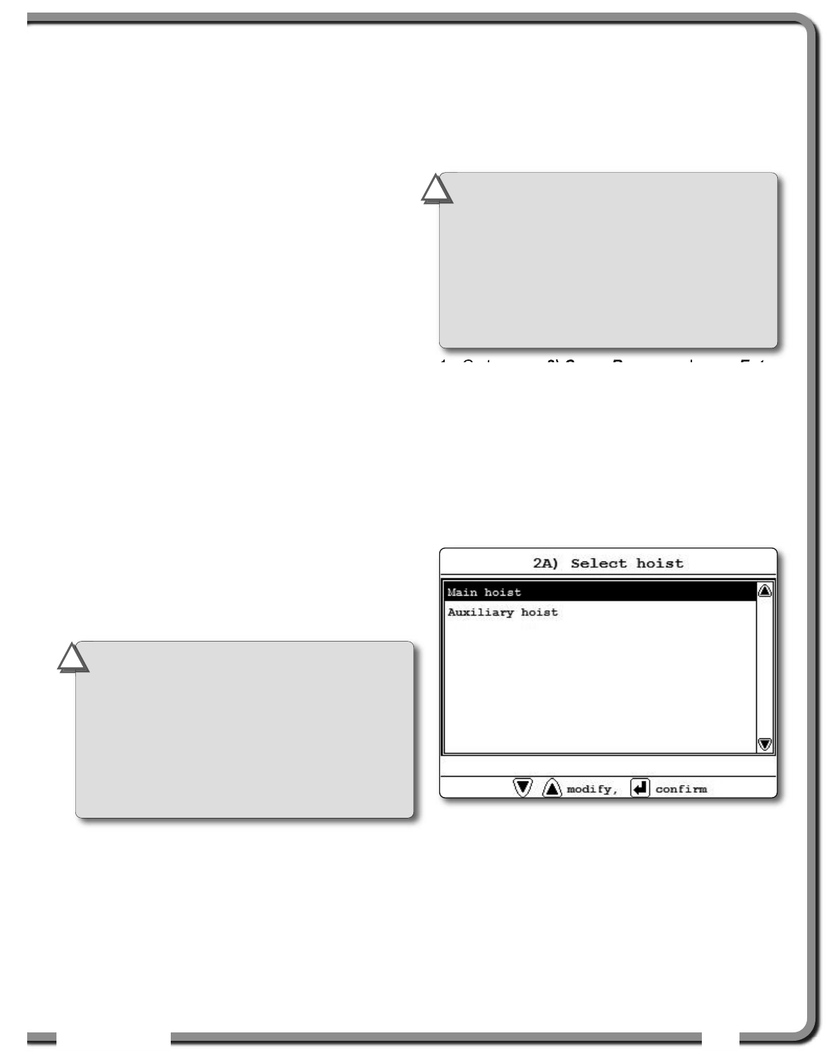
2. The first page of the chart wizard is “select
hoist”. Use Up and Down to select the hoist
and press Enter. If there is only one load
sensor in the system select “MAIN”. With two or
more load sensors in the system the main hoist
is associated with the first load sensor in the
sensor list; the auxiliary hoist is associated with
the second sensor in the sensor list etc.
3. The steps that follow will depend on the size
and complexity of the rated capacity chart itself.
Typical steps include chart selection, outrigger
/ on rubber selection and boom length selection
(lattice cranes only). Use Up and Down to
select from the list of choices and then press
Enter to advance to the next step. For accurate
rated capacity indication the rigging
configuration selected in the chart wizard must
reflect the actual rigging of the working sheave.
IMPORTANT!
It is possible to leave the
chart wizard at any time by pressing
BYPASS/EXIT;the GS820 will display the
message “RIGGING ABORTED”. Current capacity
chart selection may have changed, possibly
changing the rated capacity indicated by the
GS820. Always complete the chart wizard all
the way to the “Rigging ok” message before
operating the crane.
!
!
IMPORTANT!
If the chart number
information screen says “CHART NOT
AVAILABLE”, no chart is loaded in the GS820
and “CHART NOT USED”, the GS820 has not
been programmed to function as a rated
capacity indicator. If rated capacity indication
is required contact the person responsible for
the GS820 system installation and maintenance.
If in doubt, contact LSI
LSI.
!
!
Figure: Select hoist menu
38
38 The GS820 System
The GS820 System
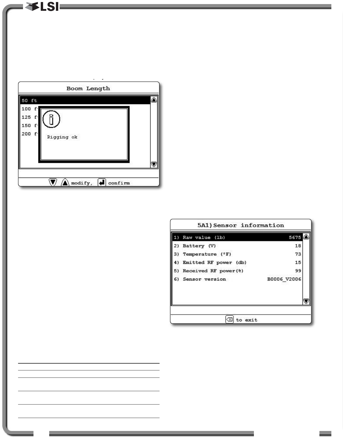
4. After the last step has been completed, the
GS820 displays “RIGGING OK” and then returns
to menu 2). Press Exit to return to the operation
display or press Enter to rig another hoist. If a
sensor required by the selected capacity chart
is not a part of the system or has not
established communication with the GS820,
then the GS820 will display “SENSOR INVALID”.
3.7
3.7 Display Settings
Display Settings
Program the display for operator preferences in
menu 3) DISPLAY SETTINGS.
1. Go to Menu 3) DISPLAY SETTINGS.
2. Use Up and Down to select the setting to
modify and press Enter.
3. Use Up and Down to modify the setting.
4. Press Enter to confirm.
5. Press Exit to return to the operation display.
3.7a Units
The weight units for load display may be selected
according to operator preference. Length units are
associated with weight units by default; see the
table below.
Table: Weight Units
3.7b Backlight Mode
Adjust the LCD backlight control mode to conform
to viewing and power supply conditions. The LCD
backlight can be “always on”, “always off” or on a
“four second timer”. In the “four second timer”
mode the backlight will come on for four seconds
when any button is pressed.
3.7c Wind speed units
The wind speed units can be set to “km/h”, “mph”,
“m/s” or “knot”.
3.8
3.8 System Diagnostic
System Diagnostic
Diagnose system issues with the sub menus of
menu 5) DIAGNOSTIC.
3.8a System Sensors Diagnostic
1. Go to menu 5A) SYSTEM SENSORS DIAGNOSTIC.
2. Select the sensor and press Enter to see the
sensor data in menu 5A1) SENSOR INFORMATION.
3. Press Exit to return to menu 5A) and select an
other sensor or press Exit again to return to the
operation display.
Unit Equivalent Weight Length Unit
Notes
Pound (lb) 1 lb 0.4536 kg Foot (ft.)
Kilogram (kg) 2.205 lb 1 kg Metre (m)
Short ton (T) 2000 lb 907.2 kg Foot (ft.)
United States
Long ton (T) 2240 lb 1016 kg Foot (ft.)
United Kingdom
Metric tonne (t) 2205 lb 1000 kg Metre (m)
International System (SI)
Figure: Sensor information menu
Figure: the GS820 displays “rigging ok”
OPERATIO
OPERATIO 39
39
3.8b Radio Network Diagnostic
1. Go to menu 5B2) LAST SENSORS RECEIVED.
Sensors are shown with their radio ID number
and the sensor type.
a. Use Up and Down to scroll through the list.
b. Press Exit to return to menu 5B).
3. Go to menu 5B3) SEARCH FOR SENSORS.
a. Press Enter to launch a sensor search.
4. Go to menu 5B4) BIT ERROR RATE TEST. This test
should only be conducted by LSI
LSI technical
service personnel.
5. Press Exit to return to the operation display.
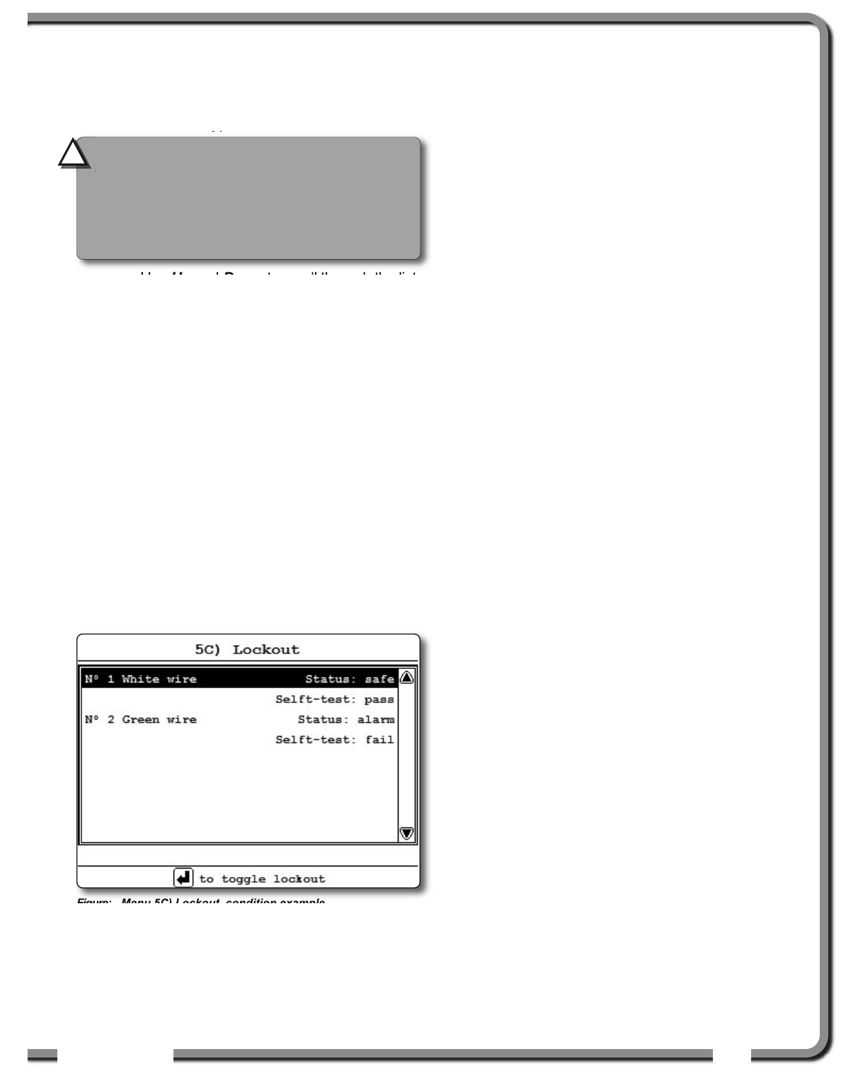
3.8c Lockout Diagnostic
Menu 5C) LOCKOUT DIAGNOSTC shows the lockout
condition of the output (alarm or safe) and the self-
test (pass or fail); it is recommended to manually test
the lockout condition;
1. Go to menu 5C) LOCKOUT. Select N° 1 WHITE
WIRE. To temporarily activate or desactivate the
lockout relay press Enter.
Figure: Menu 5C) Lockout, condition example
2. Press Down to go to N° 2 GREEN WIRE. Repeat
lockout diagnostic test.
3. Press Down to go to N° 3 ORANGE WIRE. Repeat
lockout diagnostic test.
4. Press Exit to return to the operation display.
3.8d Display Diagnostic
1. Go to menu 5D) DISPLAY DIAGNOSTIC. The page
shows different informations;
1) TIME: current time according to the GS820
internal clock.
2) DATE: current date according to the
GS820 internal clock.
3) TIME CLOCK BATTERY: self-test pass or fail.
4) EXTERNAL POWER: external power supply
voltage.
5) Display Internal temperature.
6) Base station ID. The base station ID
should be the same as the GS820 display
serial number printed on the left side of
the box.
7) Power supply
8) Radio certification: “FCC”, “IC” indicates
Federal Communications Commission
(U.S.A.) and Industry Canada
certification, “CE” indicates European
Community certification.
9) Radio frequency: the frequency used by
the system network.
8. Press Exit to return to the operation display.
3.8e Digital Input Diagnostic
1. Go to menu 5E) DIGITAL INPUT DIAGNOSTIC. The
page shows the wires digital input status (white,
green, orange and blue wires).
2. Press Exit to return to the operation display.
CAUTION!
The list of “last sensors
received” includes all functioning GS series
sensors within range. Programming a GS820
display for sensors from a different system
will disable that system and render indication
by both systems inaccurate.
!
!
40
40 The GS820 System
The GS820 System
3.9
3.9 System Limits
System Limits
Set hoist limits
The limit menu displays the limits for each sensor in
the sensor list.
1. Go to menu 6) SYSTEM LIMITS.
2. Use Up and Down to select a sensor and press
Enter to modify.
3. Use Up and Down to adjust the limit and press
Enter.
4. Press Exit to return to the operation display.
When using the GS820 as a load indicator without
programmed crane specific rated capacity charts
the load limit is typically set to the lesser of the rope
limit, the hoist limit, and the maximum allowed
capacity as determined from the capacity charts.
When using the GS820 as a rated capacity
indicator with programmed crane specific rated
capacity charts the load limit is typically set to the
lesser of the rope limit and the hoist limit.
3.10
3.10 Tare
Tare
Zero the hook
1. Go to menu 7) TARE.
2. Select the load sensor.
3. Press Enter to set or clear tare weight.
4. Press Exit to return to the operation display.
3.11
3.11 Information
Information
Go to Menu 8) INFORMATION. Standard info menu
pages include:
1. Software package
2. Firmware
3. Language pack
4. Graphic library
5. Capacity chart
6. Sensor update pkg
7. BIOS (Bootloader) number and version
8. USB driver
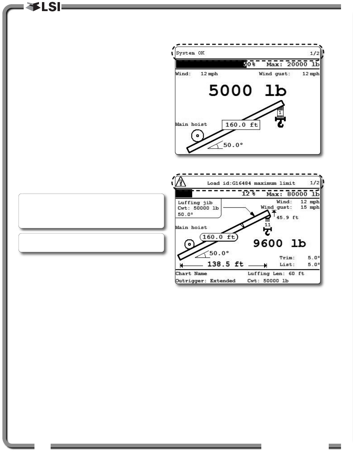
Critical system alerts or information messages are
also displayed on the top part of the LCD. See
examples below:
Note: Press Up and Down simultaneously to
return a limit to the factory default setting. The
factory default maximum limit for load sensors is
10 000 lb per part of line.
Note: When the weight units are tons the minimum
load limit increment is 0.1 ton per part of line.
Figure: the GS820 displays “system ok”
Figure: the GS820 displays an information alert
OPERATIO
OPERATIO 41
41
Table: Information Alerts Table: Information Alerts (Continued)
* If the lockout relay is inverted this alert will occur
when voltage is detected on the wire when safe.
** If the lockout relay is inverted this alert will occur
when voltage is not detected on the wire in alarm.
Alert:
“LOAD ID: G15000 MAXIMUM LIMIT”
Description:
The sensor indicates a value greater than the
operator adjusted limit.
• Verify operator adjusted limits in the limit menu.
WARNING!
Do not operate the crane
beyond the limits specified by the
manufacturer.
!
!
Alert:
“ANGLE ID: G15000 MINIMUM LIMIT”
Description:
The sensor indicates a value less than the operator
adjusted limit.
• Verify operator adjusted limits in the limit menu.
WARNING!
Do not operate the crane
beyond the limits specified by the
manufacturer.
!
!
Alert:
“LOAD ID: G15000 LOW BATTERY”
Description:
Less than 10% of battery life remains in the sensor.
• Schedule battery replacement for the next
available opportunity. Typically several weeks
of operation remain from the moment the
sensor low battery warning is first triggered.
Alert:
“LOAD ID: G15000 NOT RECEIVED”
Description:
The display isn’t receiving communication from the sensor.
• Verify that the sensor ID number programmed
matches the ID number of the sensor installed
on the crane. Go to menu 5A1.
Alert:
“VERIFY WHITE WIRE (UNEXPECTED VOLTAGE)”
Description:
Voltage is detected on the lockout wire when in alarm*.
With the standard relay configuration voltage should not
be present on a lockout wire in alarm condition.
• Verify the wire connection. Refer to the Power Supply
and Lockout Connection sub section of this manual.
Alert:
“VERIFY WHITE WIRE (SHORTED TO GROUND)”
Description:
Voltage is not detected on the lockout wire when
safe**. With the standard relay configuration voltage
should be present on a lockout wire in safe condition.
• Verify the wire is not shorted to ground.
• Verify the wire is not connected directly to the
valve coils; a relay should be installed between
the wire and the valve coils. Refer to the Power
Supply and Lockout Connection sub section of
this manual.
Alert:
“MAIN OUT OF CHART”
Description:
One or more primary conditions of the chart selected
for the hoist is not met (example: telescopic boom
length).
• Verify the conditions of the selected rated
capacity chart.
Alert:
“MAIN ANGLE ABOVE CHART MAXIMUM”
Description:
The boom or jib angle is above the maximum angle
permitted by the selected chart. (For charts
determined by radius only, this message will occur
when the radius is less than the minimum radius
permitted by the chart).
• Verify the boom and jib angles permitted by the
rated capacity chart selected.
Alert:
“MAIN ANGLE BELOW CHART MINIMUM”
Description:
The boom or jib angle is under the minimum angle
permitted by the selected chart. (For charts
determined by radius only, this message will occur
when the radius is greater than the maximum radius
permitted by the chart).
• Verify the boom and jib angles permitted by the
rated capacity chart selected.
42
42 The GS820 System
The GS820 System
Download data or upload capacity charts using a
USB mass storage device (USB key) without
removing the display from the crane.
4.1
4.1 Data logger transfer from
Data logger transfer from
Display
Display
4.1a Transfer from display to USB
1. Make sure there is at least 8 MB of available
space on the USB key. Connect the USB key
in the USB port, on the left side of the display.
2. After a short delay (about 2 seconds), the “USB
MENU” shows up on the LCD.
3. Select “COPY DATALOG. TO USB” and press
Enter. In most case, you will be prompted to
enter a password; enter the download password
given by LSI
LSI and press Enter. Press Enter once
again to confirm the data logger download.
4. Transfer progress is indicated on screen.
5. When the transfer is done, “TRANSFER
SUCCESSFUL” will appear. Press Enter, then
unplug the USB key.
6. The crane is now ready for operation.
4.1b Transfer from USB device to PC
1. Connect the USB key to a computer.
2. The data logger file is located in the root
directory of the USB device:
“LSI_MM_dd_yyyy_hh_mm_ss.dtl” where the
double letters represent the time and date of the
USB transfer. The size of the file should be 8192 kb.
4.1c Troubleshooting
Problem:
The file does not appear on the USB key.
Solution 1: Did the transfer complete successfully?
Try again.
Solution 2: Look in the root directory of the USB
key? The root directory is the folder that appears
when you open the USB key.
Problem:
The file appears on the key but its size is 0 kb.
Solution: Did the transfer complete successfully?
Try again.
Problem:
The following message appears on screen during the
transfer: “UNABLE TO CREATE FILE. REPLACE USB”
Solution 1: The USB device may not work correctly.
Replace the USB device.
Solution 2: The USB device may be in read only
mode. Allow read/write permissions.
Problem:
An error message appears on screen during the
transfer: “ERROR ##“, where ## is the error number.
Solution: restart the GS820 and try again to
transfer the file. If the trouble persists, contact LSI
LSI.
Problem:
Nothing happens when the USB key is inserted into
the USB port of the display.
Solution: Insert the USB key in the USB port, power
down and then power up the display.
4.
4. USB TOOL
USB TOOL
GS820
USB Key
Figure: Transfer charts or data logger files
USB Port
Figure: USB port location
CAUTION!
Before transferring (or
downloading) data logger or firmware
updates, make sure the crane is stopped and
is in a safe state. The crane cannot be
monitored during the download process.
!
!
IMPORTANT!
To copy the data logger to
the USB key, a password is required;
contact LSI
LSI to get the download password.
The Display ID will be asked by LSI
LSI.
!
!
USB TOOL
USB TOOL 43
43
4.2
4.2 Upload Capacity Charts
Upload Capacity Charts
1. Connect the USB key to a computer and copy
the updated chart on the USB key.
2. Connect the USB key in the USB port.
3. After a short delay (about 2 seconds), the “USB
MENU” will show up on the LCD. Select “GET FILE
FROM USB” and press Enter.
4. Choose the file to upload and press Enter.
Example typical file name: “
SPKG3_XXXX.820
”
5. A password may be required; enter the upload
password given by LSI
LSI and press Enter.
6. Transfer progress is indicated on screen.
7. When the transfer is done, “TRANSFER
SUCCESSFUL” will appear. Press Enter and then
unplug the USB key. The GS820 will restart by
itself.
4.3
4.3 Data Logger Viewer
Data Logger Viewer
The data logger viewer is a software application
used to display the data logger log file on a
personal computer (PC).
The data logger viewer converts the log file to a text
(binary) file, and then displays the contents. Two
reports can be produced and transferred to Excel,
the full report and the wind speed report.
4.3a Installation on a PC
Install the CD in a CD-ROM drive. The interactive
installation process should start automatically within
30 seconds; if not then:
1. Click Start.
2. Click My Computer.
3. Double-click on the CD-ROM drive.
4. Double-click on setup.exe.
5. Complete the installation as instructed on
screen.
4.3b Quick Start
1. Start the data logger viewer application.
2. Open the log file (see section 4.1b). Only
.dtl
files generated by the GS820 data logger can be
displayed.
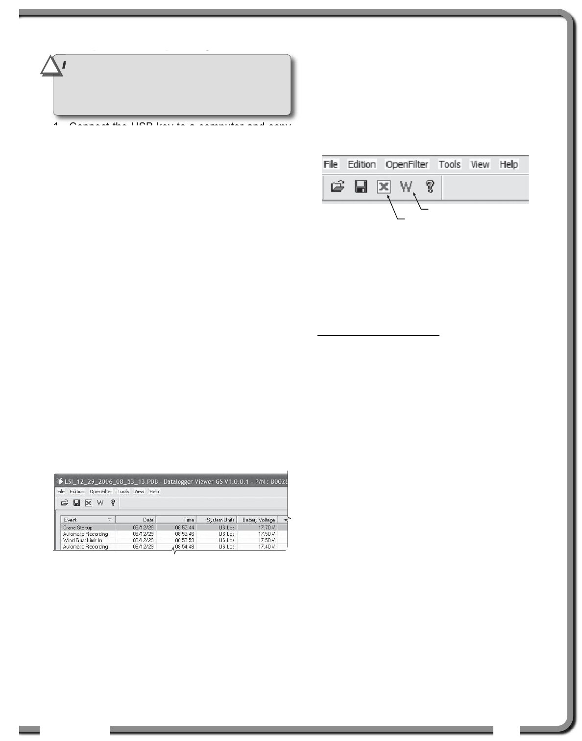
4.3c Full Report
To export the full report to Excel, click on the Full
Report button in the tool bar.
Table: Full report column headings
Column Description
Event ..................Record trigger*
Date ....................Event date stamp.
Time....................Event time stamp.
System Units......Length units (metric or US) and weight
units at the time of the event.
Battery Voltage ..Display power supply voltage at the
time of the event.
Temperature ......Internal temperature of the display.
Firm. Version......Display firmware version at the time of
the event.
Sensor # 1..........Sensor type: the sensor number
corresponds to the sensor list
programmed in the GS820.
Sensor Status ....Sensor was active or inactive at the
time of the event.
Sensor Battery ..Sensor battery level.
Value ..................Sensor value.
* Examples: Crane start-up, sensor alarm. The beginning
and end of sensor alarms are indicated as “in” and “out”:
examples: “overload in”, “overload out”.
Full Report button
Wind Report button
Figure: Data Logger Viewer tool bar
Figure: Excerpt of a full report in Data Logger Viewer
IMPORTANT!
Contact LSI
LSI to get the upload
password; this password changes according to
the random number indicated on the LCD. Please
provide the random number to LSI
LSI.
!
!
44
44 The GS820 System
The GS820 System
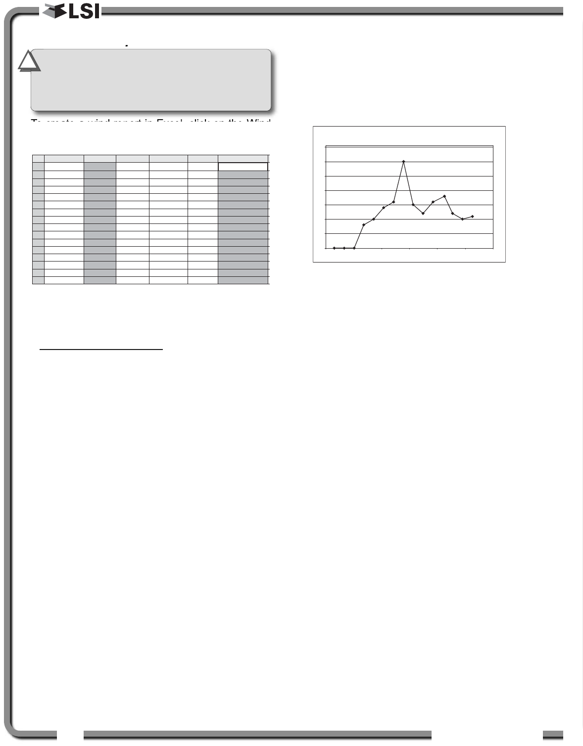
4.3d Wind Report
To create a wind report in Excel, click on the Wind
Report button in the tool bar.
Table: Wind report column headings
Column Description
Date ....................Date of event recorded
Time....................Time of event recorded
Sensor ID ..........Wind speed sensor ID number
Wind (mph) ........Average wind speed during the period
Nb. Gust ............Number of gusts exceeding the wind
speed maximum limit during the period.
Max. Gust (mph) Maximum wind speed (gust) during the
period.
Wind charts. The data from the Wind or Max Gust
columns can be easily charted.
1. Press Control and select the time column and
either the Wind or the Max Gust column.
2. Click Insert → Chart
3. Select X-Y (Scatter)
A
Date
2006-12-28
2006-12-28
2006-12-28
2006-12-28
2006-12-28
2006-12-28
2006-12-28
2006-12-28
2006-12-28
2006-12-28
2006-12-28
2006-12-28
2006-12-28
2006-12-28
2006-12-28
B
Time
17:17:41
17:18:42
17:19:43
17:20:44
17:21:45
17:22:46
17:23:47
17:24:49
17:25:50
17:26:51
17:27:52
17:29:03
17:29:54
17:30:55
17:31:56
C
Sensor ID
10033
10033
10033
10033
10033
10033
10033
10033
10033
10033
10033
10033
10033
10033
10033
D
Wind (mph)
0
0
0
5
6
8
12
22
13
9
9
8
8
7
7
E
Nb.Gust
0
0
0
0
0
0
0
1
0
0
0
0
0
0
0
1
2
3
4
5
6
7
8
9
10
11
12
13
14
15
16
F
Max.Gust (mph)
0
0
0
8
10
14
16
30
15
12
16
18
12
10
11
Figure: Excerpt of a Wind Report
Figure: Max. Gust Chart
IMPORTANT!
The wind report is only
available when the data has been recorded
with the data logger in the automatic
recording mode.
!
!
0
5
10
15
20
25
30
35
17:16:48 17:19:41 17:22:34 17:25:26 17:28:19 17:31:12 17:34:05
Max.Gust (mph)
MAITEACE
MAITEACE 45
45
5.1
5.1 Sensors
Sensors
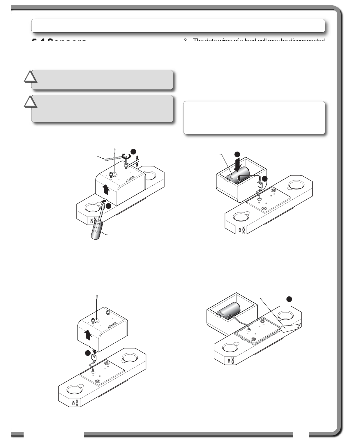
5.1a Replacing Sensor Battery
1. Unscrew the two allen screws about a quarter
of an inch.
2. Insert a flat bladed screwdriver in the battery
cover notch to pry the box away from the
mounting plate. The silicone seal may cause
some resistance.
3. The data wires of a load cell may be disconnected
to facilitate battery replacement.
4. Remove the battery by hand.
5. Remove the remaining silicone from both the
box and the mounting plate.
6. Install the new battery: insert the positive end and
then push in the direction of the positive pole.
7. Reconnect the data wires if disconnected.
8. Apply a non-corrosive RTV silicone all around
the edge of the mounting plate to create a new
seal without bubbles or breaks.
9. Reposition the box over the mounting plate and
screw in the hex screws. Do not overtighten.
5.
5. MAINTENANCE
MAINTENANCE
1/4 in.
1
2
Hex key 5/32 in.
Flat bladed screwdriver
6
7
New high quality “D”
cell battery: 3.6 V lithium,
or alkaline
Figure: Remove the sensor box from the mounting plate
* Actual battery life will vary greatly depending on
the application, the frequency of use, the age and
quality of the battery etc.
3
Figure: Disconnect the data wires
8
RTV non-corrosive
silicone
Figure: Install the new battery and reconnect the data wires
Figure: Apply non-corrosive RTV silicone
IMPORTANT!
Protect the interior of the
sensor from dirt and humidity at all times.
!
!
Note: A 3.6 volt lithium “D” cell battery will provide
about two years of battery life for a load cell, while
an alkaline “D” cell battery will provide less than
one year of battery life*.
IMPORTANT!
Both lithium or alkaline
batteries can be used, however lithium
battery will last about 2.5 times longer.
!
!
46
46 The GS820 System
The GS820 System
5.2
5.2 Anti-Two-Block switch
Anti-Two-Block switch
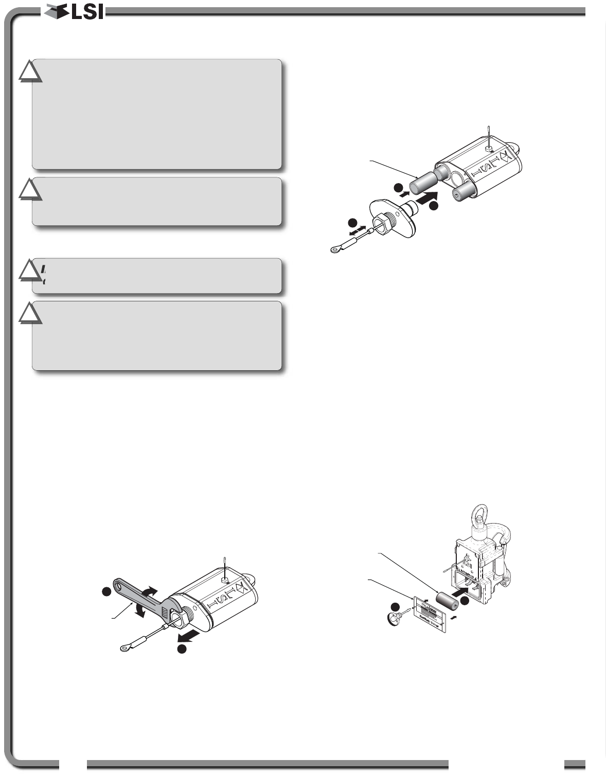
5.2a Replacing the GS050 Batteries
This procedure does not apply to the GS005
mechanical anti-two-block transmitter; please refer
to the Replacing Sensor Battery section.
1. Remove the anti-two-block from the crane and
clean off dust and grime.
2. Place the anti-two-block on the edge of flat
surface. Use an adjustable wrench to unscrew
the large white nylon hex bolt of the wire rope
about one half-inch.
3. Carefully remove the plunger assembly without
separating it from the cover, and place it on a
clean and dry surface.
4. Slide out the four old batteries.
5. Insert the four new batteries following the
positive - negative schematic printed on the
back of the sensor.
6. Replace the plunger assembly. Correctly align
the bottom cover before screwing in the white
nylon hex bolt of the wire rope. Tighten well.
7. Pull and release the wire rope, the light emitting
diode (LED) on the bottom of the sensor should
flash red.
8. Reinstall the anti-two-block switch.
9. Test the anti-two-block system for alarm and
lockout before operating the machine.
5.2b Replacing the GS075 Battery
1. Remove the GS075 anti-two-block from the
crane and clean off dust and grime.
2. Unscrew the two screws of the battery cover
and remove the battery cover.
3. Remove the battery by hand.
4. Insert the new battery following the positive -
negative schematic.
5. Reposition the battery cover and screw in both
screws.
6. Reinstall the anti-two-block switch.
7. Test the anti-two-block system for alarm and
lockout before use.
2
3
A
djustable
wrench
Figure: Remove the plunger assembly of the GS050
6
5
7
New high quality “C”
cell battery: 3.6 V lithium,
or alkaline
Figure: Install the new batteries and the plunger
IMPORTANT!
Replace all the batteries of
the anti-two-block switch at the same time.
Unchanged batteries will reverse polarity
severely reducing battery life.
IMPORTANT!
Protect the interior of the
anti-two-block switch from dirt and humidity
at all times.
!
!
IMPORTANT!
Do not unscrew the white
nylon hex bolt of the antenna.
IMPORTANT!
Do not unscrew the small
screw to the left of the antenna.
!
!
IMPORTANT!
Class I Div I sensors certified by
CSA or ATEX should use alkaline batteries only.
!
!
New high quality “D”
cell battery: 3.6 V lithium,
or alkaline
Battery
cover
4
2
Figure: Replacing GS075 battery
IMPORTANT!
Both lithium or alkaline
batteries can be used, however lithium
battery will last about 2.5 times longer.
!
!
MAITEACE
MAITEACE 47
47
5.3
5.3 Replacing a Sensor
Replacing a Sensor
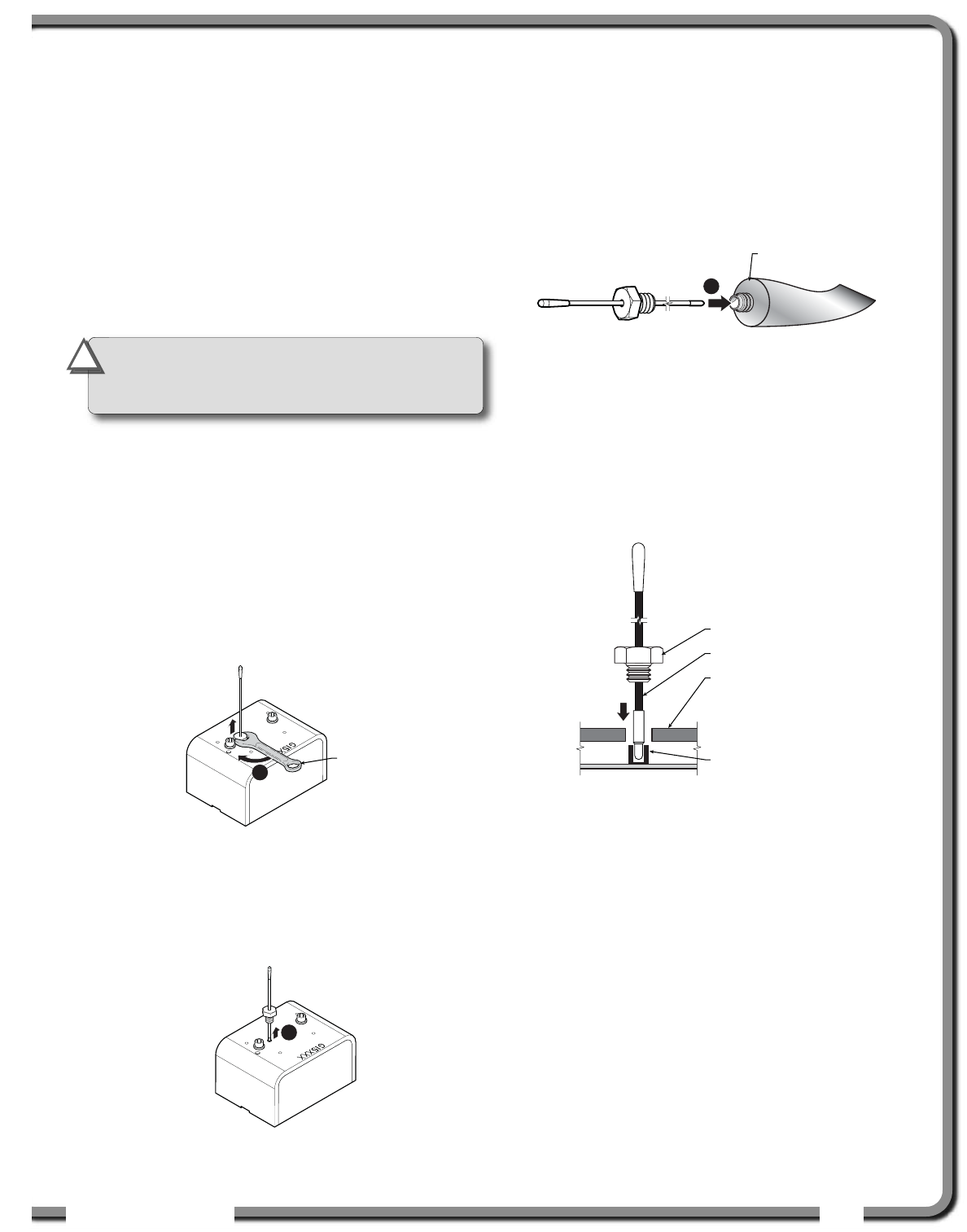
Antenna
Antenna
Heavily damaged antennas (ripped out, sheared off,
wire exposed and fraying etc.) should be replaced
to ensure effective communication between the
sensor and the cabin mounted display unit.
This procedure may be followed without removing the
sensor from the crane if it is safe to do so. If removed,
an angle sensor must be re-calibrated during
reinstallation for correct angle display (see the angle
sensor installation section of the user’s manual).
1. Place the crane, boom, jib or ball hook such that
the sensor is safely accessible.
2. Clean dust, grime and water from the sensor.
3. Identify the short black whip antenna and the
white hex bolt securing it.
4. Inspect the antenna for signs of obvious
physical damage.
5. Carefully unscrew the white nylon hex bolt
completely and slide it up the antenna.
6. Grip the antenna by the base of the black plastic
sheathing and pull it straight out of the hole in
which it is seated. Place the old antenna aside.
7. Slide the white nylon hex bolt to the middle of
the length of the new antenna.
8. Coat the exposed metal foot of the new antenna
with an electrical insulating compound by
carefully inserting it in the mouth of the
compound tube.
9. Hold the new antenna by the black plastic
sheathing and guide it through the hole in the
sensor box. Carefully seat the antenna in its
mating connector. When the antenna is
correctly seated, pulling on it will be met with
light resistance.
10.Carefully re-thread, screw-in and tighten the
white nylon hex bolt to secure the antenna in
place. Do not overtighten.
11. Reinstall the sensor if necessary (if removed
from the boom or jib, an angle sensor will
require re-calibration during the installation
procedure, see the angle sensor installation
section of the user’s manual).
12.Verify that the sensor functions properly.
5
7/16 in.
wrench
Figure: Unscrew the white nylon hex
6
Figure: Pull out the antenna
8
Electrical insulating
compound
Figure: Coat the exposed metal foot of the antenna
White nylon hex bolt
TA011 Antenna
Sensor box
Antenna receptacle
Figure: Install the new antenna
IMPORTANT!
The interior of the sensor
must be protected from dust, grime and
water at all times.
!
!
48
48 The GS820 System
The GS820 System
5.4
5.4 Load Cells
Load Cells
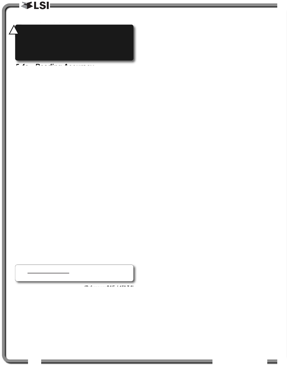
5.4a Reading Accuracy
LSI
LSI flat bar load links are pre-calibrated at the
factory. No “zeroing” or other calibration is required
on installation. Each link is heat treated to age the
steel and ensure stable readings for many years; the
load cells are individually temperature compensated
to guarantee accuracy. LSI
LSI flat bar load links are
calibrated to indicate between 100% and 104% of
their Safe Working Load (SWL).
LSI
LSI load pins, line riding tensiometers and
compression cells must be calibrated at installation
and every time thereafter the installation, the load
sensor or the transmitter is changed.
SAE J 159 4.2.1 recommends load indicating
devices should show not less than 100% of the
actual load and not more than 110% of the actual
load.
5.4b Load Testing
LSI
LSI recommends testing the load cell every year for
accuracy. The simplest way of testing a load cell is to
lift at least two known weights. A test weight should be
known with an accuracy of ±1%. If the load cell is
installed at the boom tip dead end, all additional
equipment such as blocks, slings, sensors, etc. should
also be known to an accuracy of ±1%.
Determine the accuracy of the tested system with
the following formula:
(Reference: SAE-J-159 7.3)
The test loads must be significantly relative to the
load cell capacity. The minimum test weight is
about 20% of the safe working load; a good test
weight is greater than 50% of the SWL. For
example, a 30 000 lb load cell on four parts of line
has a SWL of 120 000 lb; the minimum test load in
this case would be 24 000 lb, a good test load
would be 60 000 lb or more.
5.4c Care
Battery. Lithium batteries older than 18 months old
(alkaline batteries over 6 months old) should be
changed at the first available planned inspection
even if there is not yet a low battery warning. This
will avoid costly delays in the field.
Corrosion. Verify that no corrosion is visible on the
battery holder inside the load cell transmitter. If some
trace of corrosion is visible, rub it off gently and put
a small amount of dielectric grease* on each battery
holder post to protect the contacts.
Mechanical stresses. Verify the load cell sides for
dents or heavy scratches. The side of the load cell
under the transmitter box is the most sensitive
region. Engraving a number in this area will affect
load cell accuracy and reliability. If the transmitter
box has been hit and the box does not fit perfectly to
the underlying link, please call LSI
LSI to have it
repaired. Engraving on the transmitter box sides will
not affect reading.
Seal. If the transmitter box has been removed it
must be correctly resealed with RTV non-corrosive
silicone.
Antenna. Small scratches on the antenna will not
affect radio communications. A heavy bending of the
antenna or bare sections on the wire may reduce
the radio efficiency.
Hex bolts. The hex head bolts on the transmitter
box are there to protect the antenna and to hold the
transmitter box on the load cell link. If one or both
hex nuts are scratched, it will not affect the load cell
readings or operation. If the bolt head is bent or
sheared verify that the transmitter box fits tightly to
the load cell link before contacting LSI
LSI for
replacement bolts.
Indicated Load
Actual Load X 100 = % of Load
* Dow Corning dielectric grease № 4
WARNING!
Heavy shock may affect load
indication accuracy. Inspect the load cell
regularly for clearly visible dents or
scratches. Test the load indication if collision
damage is visible.
!
!

TROUBLESHOOTIG
TROUBLESHOOTIG 49
49
Display Not On
1. Verify the connection between the yellow cable
wires and the crane power supply
2. Verify the crane battery, the fuse and the
accessory switch.
3. Carefully disconnect the yellow cable from the
display unit and reconnect it.
Display In Alarm
1. Identify the sensor in alarm. Place the sensor
in safe condition (press Bypass if necessary).
2. Verify that the limits, the parts of line and the
tare are correctly adjusted.
3. Verify all sensor batteries: see Battery
Diagnostic troubleshooting section.
4. Verify the red light on the sensor box flashes
(release the wire rope of an anti-two-block,
change the load on a load sensor, change the
angle of an angle sensor, change the boom
length of a length sensor).
5. Verify radio communication: see Radio
communication troubleshooting section.
Sensor Malfunction
1. Verify the sensor batteries: see Battery
Diagnostic troubleshooting section.
2. Verify the red light on the sensor box flashes
(release the wire rope of an anti-two-block,
change the load on a load sensor, change the
angle of an angle sensor, change the boom
length of a length sensor).
3. Verify radio communication: see Radio
communication troubleshooting section.
Battery Diagnostic
Go to menu 5A) SYSTEM SENSORS DIAGNOSTIC. Select
a sensor and press Enter to verify the sensor status.
•"B: 50%": 50% of battery life remains (typically
several months).
•"INTIMEOUT": communication not yet
established. Verify the radio ID corresponds to
the installed sensor.
• Battery status is usually known within 2
minutes. When 10% or less battery life remains,
for any sensor, a message will be generated
(the Info alert light will flash). Follow the battery
diagnostic procedure to identify the sensor.
Batteries do not need to be replaced before the
LOW BATTERY message is generated. Usually
several days, or weeks, of operation remain
from the moment the LOW BATTERY message
comes. A new high quality alkaline or lithium ‘D’
cell battery may be used.
Radio communication
1. Verify that the antennas have a direct clear line
of sight to each other.
2. Verify that the antennas do not point directly
towards, or directly away from, each other.
3. Verify that the antennas are not in contact with
metal other than the sensor itself.
4. Verify the antenna for damage.
5. Go to menu 5A) SYSTEM SENSORS DIAGNOSTIC.
Select a sensor and press Enter to verify the
sensor status.
•“R: 85%” means radio reception is at 85%.
Lockout Malfunction
1. Verify the connections of the lockout wire(s)
(white, green, orange, blue).
2. Verify lockout coil connections.
3. Verify correct relay installation for lockout
systems drawing more than one ampere on the
white wire.
4. Carefully disconnect the yellow cable from the
display unit and reconnect it.
6.
6. TROUBLESHOOTING
TROUBLESHOOTING
50
50 The GS820 System
The GS820 System
7.1
7.1 FCC and IC – Instructions
FCC and IC – Instructions
to the User
to the User
This equipment has been tested and found to comply
with the limits for a class B digital device, pursuant to
part 15 of the FCC Rules. These limits are designed
to provide reasonable protection against harmful
interference in a residential installation. This
equipment generates, uses, and can radiate radio
frequency energy and if not installed and used in
accordance with the instructions, may cause harmful
interference to radio communications. However,
there is no guarantee that interference will not occur
in a particular installation. If this equipment does
cause harmful interference to radio or television
reception, which can be determined by turning the
equipment off and on, the user is encouraged to try
to correct the interference by one or more of the
following measures:
• Reorient or relocate the receiving antenna.
• Increase the separation between the equipment
and receiver.
• Connect the equipment into an outlet on a
circuit different from that to which the receiver is
connected.
• Consult the dealer or an experienced radio/TV
technician for help.
In order to maintain compliance with FCC
regulations, shielded cables must be used with this
equipment. Operation with non-approved equipment
or unshielded cables is likely to result in interference
to radio and TV reception.
FCC ID: QVBGS820 IC: 7076A-ICGS820
RF Exposure Warning:
This product complies with FCC/IC radiation
exposure limits set forth for an uncontrolled
environment. To comply with RF exposure
requirements, the unit must be installed and
operated with 20 cm (8 in.) or more between the
product and your body. This product may not be
collocated or operated in conjunction with any
other antenna or transmitter.
This device has been designed to operate with
the antennas listed below, and having a
maximum gain of 2.0 dB. Antennas not included
in this list or having a gain greater than 2.0 dB
are strictly prohibited for use with this device.
The required antenna impedance is 50 ohms.
To reduce potential radio interference to other
users, the antenna type and its gain should be
so chosen that the equivalent isotropically
radiated power (e.i.r.p.) is not more than that
permitted for successful communication.
Antenna List
LSI P/N: TA001
Description: 1/4 wave monopole
MFG Linx Technologies
P/N ANT-916-CW-QW
LSI P/N: TA008
Description: 1/2 wave dipole
MFG: Nearson
P/N: S467AH-915S
FCC ID: QVBGS000 IC: 7076A-ICGS000
FCC ID: QVBGS050 IC: 7076A-ICGS050
FCC ID: QVBGS075 IC: 7076A-ICGS075
RF Exposure Warning:
This product complies with FCC/IC radiation
exposure limits set forth for an uncontrolled
environment. To comply with RF exposure
requirements, the unit must be installed and
operated with 20 cm (8 in.) or more between the
product and your body. This product may not be
collocated or operated in conjunction with any
other antenna or transmitter.
This device has been designed to operate with
the antennas listed below, and having a
maximum gain of 3.0 dB. Antennas not included
in this list or having a gain greater than 3.0 dB
are strictly prohibited for use with this device.
The required antenna impedance is 50 ohms.
To reduce potential radio interference to other
users, the antenna type and its gain should be
so chosen that the equivalent isotropically
radiated power (e.i.r.p.) is not more than that
permitted for successful communication.
Antenna List
LSI P/N: TA011
Description: 1/4 wave monopole
MFG Load Systems International
7.
7. CERTIFICATION NOTES
CERTIFICATION NOTES
IMPORTANT!
Changes or modifications to
this equipment not expressly approved by the
party responsible for compliance could void
the user’s authority to operate the equipment.
!
!

GS820 MEU OUTLIE
GS820 MEU OUTLIE 51
51
1) PARTS OF LINE
2) CRANE RIGGING
3) DISPLAY SETTINGS
1) Weight units
2) Display language
3) Backlight mode
4) Wind speed units
4) INSTALLATION
4A) SENSOR LIST
4A1) SENSOR TYPE AND RADIO IDENTIFICATION
NUMBER
1. Configuration select (automatic, manual)
2. Configuration number
3. Start up page
4B) SENSOR CALIBRATION
4B1) AUTOMATIC VALUE CALIBRATION WIZARD
4B2) MANUAL PARAMETER ADJUSTMENT
4B3) RESET SENSOR PARAMETERS
4C) RADIUS SETTINGS
1) Boom length
2) Slew offset
3) Height offset
4) Boom deflection
5) Boom top length
6) Boom top offset
7) No load deflection
8) Jib offset
9) Lattice extension offset
10) Jib mounting point perpendicular
11) Jib mounting point parallel
12) Main hoist
12A) Jib length
12B) Luffing jib length
12C) Lattice extension length
12D) Manual length
12E) Sheave head length perpendicular
12F) Sheave head length parallel
12G) Sheave radius
12H) Deduct
13) Auxiliary hoist
13A) Jib length
13B) Luffing jib length
13C) Lattice extension length
13D) Manual length
13E) Sheave head length perpendicular
13F) Sheave head length parallel
13G) Sheave radius
13H) Deduct
14) Auxiliary hoist 2
14A) Jib length
14B) Luffing jib length
14C) Lattice extension length
14D) Manual length
14E) Sheave head length perpendicular
14F) Sheave head length parallel
14G) Sheave radius
14H) Deduct
15) Auxiliary hoist 3
15A) Jib length
15B) Luffing jib length
15C) Lattice extension length
15D) Manual length
15E) Sheave head length perpendicular
15F) Sheave head length parallel
15G) Sheave radius
15H) Deduct
16) Auxiliary hoist 4
16A) Jib length
16B) Luffing jib length
16C) Lattice extension length
16D) Manual length
16E) Sheave head length perpendicular
16F) Sheave head length parallel
16G) Sheave radius
16H) Deduct
17) Auxiliary hoist 5
17A) Jib length
17B) Luffing jib length
17C) Lattice extension length
17D) Manual length
17E) Sheave head length perpendicular
17F) Sheave head length parallel
17G) Sheave radius
17H) Deduct
4D) CHART SETTINGS
1) Rated capacity indicator
2) Crane capacity chart interpolation
3) Out of charts default working load limit
4) Enable start section
5) Enable stop section
6) Retracted boom length tolerance
7) Intermediate boom length tolerance
8.
8. GS820 MENU OUTLINE
GS820 MENU OUTLINE

52
52 The GS820 System
The GS820 System
8) Extended boom length tolerance
9) Radius tolerance
10) Boom angle tolerance
4E) MEMORY BANKS
1) Save config. A (Copy configuration to
memory bank A)
2) Save config. B (Copy configuration to
memory bank B)
3) Save config. C (Copy configuration to
memory bank C)
4) Get config. A (Copy memory bank A to
current configuration)
5) Get config. B (Copy memory bank B to
current configuration)
6) Get config. C (Copy memory bank C to
current configuration)
7) Restore default (Restore factory
configuration)
8) Clear configuration
4F) DATA LOGGER
1) Data logger mode
2) Adjust date
3) Adjust time
4G) LOCKOUT SETTINGS
1) Warning level
2) Alarm level
3) Lockout level
4) White wire lockout trigger
5) Green wire lockout trigger
6) Orange wire lockout trigger
7) Blue wire lockout trigger
8) Lockout relay inverted
4H) PASSWORD SETTINGS
1) Administrator password
2) User password
3) Tare menu password protection
4) Limit menu password protection
5) Info menu password protection
6) System start-up password protection
7) Parts of Line menu password protection
8) Chart Rigging password protection
9) Display Settings password protection
10) Sensor List password protection
11) Sensor Calibration password protection
12) Radius Settings password protection
13) Chart Settings password protection
14) Memory Banks password protection
15) Data logger password protection
16) Lockout Settings password protection
17) Network Options password protection
18) System Diagnostic password protection
19) Alarm Bypassed protection
4I) NETWORK OPTIONS
4I1) NETWORK CONTROL
4I2) REPEATER LIST
4I3) SET UP SENSOR REPEATER
4I4) INSTALL SENSOR UPDATE
5) SYSTEM DIAGNOSTIC
5A) SYSTEM SENSORS DIAGNOSTIC
5B) RADIO NETWORK DIAGNOSTIC
5B1) RADIO NETWORK
5B2) LAST SENSORS RECEIVED
5B3) SEARCH FOR SENSORS
5B4) BIT ERROR RATE TEST
5C) LOCKOUT DIAGNOSTIC
5D) DISPLAY DIAGNOSTIC
1) Time
2) date
3) Time clock battery test
4) External power supply voltage
5) Internal temperature
6) GS820 base station identification number
7) GS820 (portable) battery level
8) Radio certification
9) Radio frequency
5E) DIGITAL INPUT DIAGNOSTIC
6) SYSTEM LIMITS
7) TARE
8) INFORMATION
1. Software package
2. Firmware
3. Language pack
4. graphic library
5. capacity chart
6. sensor update pkg
7. bios
8. usb driver

LSI PRODUCT LIMITED WARRATY
LSI PRODUCT LIMITED WARRATY 53
53
9.1
9.1 Limited Warranty
Limited Warranty
LOAD SYSTEMS INTERNATIONAL INC. (hereafter
“LSI
LSI”) warrants its products (the “Products”), for a
period of twenty four (24) consecutive months after
delivery of such Products to the user (as evidenced
on a LSI
LSI document) (the “Warranty Period”), when
installed and used in accordance with specifications
described in LSI
LSI Installer and User’s Manual, as
amended from time to time , LSI
LSI technical materials
and any related writings published by LSI
LSI with
respect with such Products and any industry
standards, will be free from defects in materials and
workmanship. During the Warranty Period, LSI
LSI or its
designated service representative shall repair, or at
its option, replace any Product that is confirmed to be
defective by LSI
LSI, in its sole discretion, in accordance
with the Limited Warranty Services Procedures
described below.
9.2
9.2 Warranty Services
Warranty Services
Procedures
Procedures
In order to benefit of this-mentioned Limited Warranty
coverages and benefits, the purchaser must notify
LSI
LSI’s customer service or LSI
LSI’s authorized distributor
or representative originally responsible for the sale of
the Products within 10 days of the occurrence of a
suspected defect in materials or workmanship, prior
to the expiry of the Limited Warranty Period in order
to obtain a Return Authorization Number. A proof of
purchase of the Product, such as an invoice or a
receipt certifying the validity of the Warranty, must be
presented in order to obtain Limited Warranty
coverage. In any event, even if a Return Authorization
Number is provided to purchaser, LSI
LSI reserves the
right to inspect the damaged Product or part before
the final decision of repairing or replacing the
defective Product or part.
The Product or part shall be returned to LSI
LSI or its
designated service representative, accompanied by
the Return Authorization Number with prepaid
shipping charges. The purchaser must insure the
shipment or accept the risk of loss or damage during
the shipment. Purchaser shall also pay any tariff or
duty applicable to the return of defective part or
Product. LSI
LSI will, at its option, repair or replace the
Product or part returned to LSI
LSI or to its designated
service representative. LSI
LSI owns all parts or Products
replaced, repaired or removed from a repaired
Product. If LSI
LSI repairs a Product, the Product
Warranty coverage Period is not extended and the
Limited Warranty shall expire as if uninterrupted upon
the occurrence of the 24th month from shipping from
LSI
LSI. If LSI
LSI replaces a Product, the replaced Product
is warranted for the remainder of the original term or
sixty consecutive (60) days, whichever is longer.
LSI
LSI reserves the right to require from you the user or
owner of the Products, prior to determining if the Limited
Warranty coverage is applicable, that LSI
LSI receive the
data logging equipment used with the Products and that
LSI
LSI be authorized to retrieve all information from such
data logging equipment in order to, among others,
ensure that the written instructions and applicable
standards, including safety margins, were respected
and not exceeded during Product use. Failure by you
the owner or user of the Product to supply such
information shall be deemed a material default of the
terms and conditions of this Limited Warranty and shall
be irrevocably construed as evidence that the Product
was misused or abused. Consequently LSI
LSI shall
irrevocably be relieved of any obligations to
compensate you the user or owner of the Product for
any and all damages resulting from Product failures
when data logging equipment, and access to its
content, cannot be freely and readily provided,
unhampered, to LSI
LSI.
LSI
LSI will pay ground freight transportation costs
of replacement or repaired parts or Products to
the destination in Canada and the continental
United States of America (the “Territory”). LSI
LSI will
not pay any transportation costs of replacement
or repaired parts to destination outside of the
Territory. Shipping and handling costs to
locations outside the Territory shall be the
responsibility and borne by Purchaser or Owner
of the Product prior to any shipment by LSI
LSI.
(Contact LSI
LSI to get a Return Authorization
Number and the address to ship parts).
9.3
9.3 Exclusion of Other
Exclusion of Other
Warranties
Warranties
THE ABOVE WARRANTY IS THE SOLE WARRANTY
APPLICABLE AND THERE ARE NO EXPRESS,
LEGAL OR IMPLIED WARRANTIES OR CONDITIONS
IN RELATION TO ANY PRODUCTS INCLUDING ANY
IMPLIED WARRANTY OR CONDITION OF
MERCHANTABILITY, NON-INFRINGEMENT OR
FITNESS FOR A PARTICULAR PURPOSE AND
THOSE OTHERWISE ARISING BY STATUTE OR
OTHERWISE IN LAW OR FROM A COURSE OF
9.
9. LSI PRODUCT LIMITED WARRANTY - 2009/02/16
LSI PRODUCT LIMITED WARRANTY - 2009/02/16

54
54 The GS820 System
The GS820 System
DEALING OR USAGE OF TRADE, WHICH ARE
EXPRESSLY DISCLAIMED. NO ORAL OR WRITTEN
INFORMATION OR ADVICE GIVEN BY LSI
LSI OR ITS
EMPLOYEES OR REPRESENTATIVES SHALL
CREATE A WARRANTY OR CONDITION OR IN ANY
WAY INCREASE THE SCOPE OF LSI
LSI’S OBLIGATION.
LSI
LSI DOES NOT WARRANT THAT THE BUSINESS
RESULTS OBTAINED FROM THE USE OF THE
PRODUCTS WILL BE APPROPRIATE OR ADEQUATE
FOR THE PURCHASER.
9.4
9.4 Exclusion
Exclusion
This Limited Warranty does not cover and shall not
apply to:
• Any Product that is misused or abused, including
being altered, modified or repaired not in
accordance to LSI
LSI written instructions or
authorizations and any use not in compliance with
LSI
LSI’s instructions and/or industry standards and
practices;
• Any incidental costs or expense, such as shipping
charges to LSI
LSI or an designated service
representative as well as the technician out-of-
pocket expenses including traveling, lodging and
meal expenses, if any;
• The damages caused during the transport or the
moving of the Products;
• Damages caused by accidents, abuse, misuse, a
force majeure (described as events outside a
LSI
LSI’s or any Product user’s control, including war,
riot, strikes, embargoes) or external cause;
• Any cost, damage or expenses for field labor or
any other expenses related to or arising from the
replacement of defective parts.
• Products used for pile-driving, wire rope activated
clamshell or dragline applications. If purchaser
uses the Products for pile-driving, wire rope
activated clamshell or dragline application, the
limited warranty will be deemed to have been
violated for abuse.
• Any costs associated with providing LSI
LSI with data
logging equipment.
9.5
9.5 Limitation of Liability
Limitation of Liability
To the maximum extent permitted by applicable law,
in no event will LSI
LSI be liable to the purchaser or any
third party for any indirect, special, consequential,
incidental or exemplary damages whatsoever,
including but not limited to loss or revenue or profit,
lost or damaged data, business interruption or any
other pecuniary loss whether based in contract, tort or
other causes of action, even if LSI
LSI has been advised
of the possibility of such damages. In any event, the
total liability of LSI
LSI arising from any cause of action or
claim whatsoever, whether (1) in contract, (2) in tort
(including negligence, whether sole, joint,
contributory, concurrent or otherwise, but not
including intentional, reckless or wanton tort), (3)
under strict liability, (4) under any environmental or
antipollution law or regulation, (5) connected with any
toxic or hazardous substance or constituent, (6)
arising out of any representation or instruction, or
under any warranty, (7) or otherwise, arising out of,
connected with, or resulting from the design,
manufacture, sale, resale, delivery, repair,
replacement or use of Products or the furnishing of
any service shall in no event exceed the price
allocable to and paid to LSI
LSI for the individual unit of
Products or service or part thereof which gives rise to
the cause of action or claim.
SOME STATES OR JURISDICTIONS DO NOT
ALLOW THE LIMITATION OR EXCLUSION OF
LIABILITY FOR INCIDENTAL OR CONSEQUENTIAL
DAMAGES, SO THE ABOVE LIMITATION OR
EXCLUSION MAY NOT APPLY TO YOU.
9.6
9.6 Recommended Practices
Recommended Practices
LSI
LSI recommends careful consideration of the
following factors when specifying and installing the
Products. Before installing a Product, the Installation,
Operation, and Maintenance instructions provided
with the unit must be read and understood and
complied with.
9.7
9.7 Choice of law
Choice of law
This Limited Warranty shall be governed by and
construed in accordance with the laws of : 1. For
Products sold in Canada: the Province of Quebec or,
For Products sold in the USA: the State of Florida,
without giving effect to principles of conflicts of law.
You agree that the exclusive venue for any disputes
arising under this Agreement shall be the state and
federal courts located in Orlando, Florida.
9.7a Entire Agreement
This document contains the entire agreement of the
parties regarding the subject matter of the Product
and supersedes all previous communications,
representations, understandings and agreements,
either oral or written, between you and LSI
LSI.


GM820 REV.20090409 www.loadsystems.com
© 2009, Load Systems International Inc.
Technical Support:
Technical Support:
LSI
LSI Technical Support is available 24 hours a day, 7 days a week from our
Houston and Dubai locations.
Please direct all technical support questions to either of these locations or
contact us via email:
techsupport@loadsystems.com
North America Middle East & Africa
Toll Free Phone: (888) 819 4355 Phone: +971 6 557 8314
Toll Free Fax: (888) 238 4099 Fax: +971 6 557 8315
International: +1 (281) 664 1330
LSI Contact Information
LSI Contact Information
USA Corporate Office:
9223 Solon, Suite A
Houston, TX 77064
Direct Phone: 281.664.1330
Direct Fax: 281.664.1390
Email: sales@loadsystems.com
Dubai Corporate Office:
Q3-171 SAIF Zone. PO Box 7976
Sharjah UAE
Phone: +971 6 557 8314
Fax: +971 6 557 8315
Email: lsifzc@emirates.net.ae
Canadian Corporate Office:
4495 Blvd. Hamel, Suite 110
Quebec QC G1P 2J7
Direct Phone: (418) 650 2330
Direct Fax: (418) 650 3340
Email: sales@loadsystems.com