Lochinvar Kight Xl 400 801 Users Manual OKBX I O Rev B
400-801 to the manual 80cf0bb2-9739-4377-a29c-de7b6c2efdd6
2015-02-09
: Lochinvar Lochinvar-Kight-Xl-400-801-Users-Manual-575391 lochinvar-kight-xl-400-801-users-manual-575391 lochinvar pdf
Open the PDF directly: View PDF ![]() .
.
Page Count: 56
Outdoor Knight XL
Installation & Operation Manual
Models: 400 - 801
Save this manual for future reference.
This manual must only be used by
a qualifi ed heating installer / service
technician. Read all instructions,
including this manual and the
Outdoor Knight XL Service Manual,
before installing. Perform steps in
the order given. Failure to comply
could result in severe personal
injury, death, or substantial property
damage.
WARNING
OKBX-I-O Rev B
2
Contents
Hazard defi nitions
The following defi ned terms are used throughout this manual to bring attention to the presence of hazards of various risk levels
or to important information concerning the life of the product.
DANGER
WARNING
CAUTION
CAUTION
NOTICE
DANGER indicates an imminently hazardous situation which, if not avoided, will result in death or serious
injury.
WARNING indicates a potentially hazardous situation which, if not avoided, could result in death or serious
injury.
CAUTION indicates a potentially hazardous situation which, if not avoided, may result in minor or moderate
injury.
CAUTION used without the safety alert symbol indicates a potentially hazardous situation which, if not
avoided, may result in property damage.
NOTICE indicates special instructions on installation, operation, or maintenance that are important but not
related to personal injury or property damage.
HAZARD DEFINITIONS .................................................... 2
PLEASE READ BEFORE PROCEEDING ........................ 3
THE OUTDOOR KNIGHT XL -- HOW IT WORKS......... 4-6
RATINGS ........................................................................... 7
1. DETERMINE BOILER LOCATION
Flooring and Foundation .................................................... 9
Prevent Combustion Air Contamination ............................. 9
Corrosive Contaminants and Sources ................................9
2. PREPARE BOILER
Remove Boiler from Wood Pallet ..................................... 10
Install Flue Pipe Assembly .......................................... 10-11
Gas Conversions .............................................................. 12
Model 400 ....................................................................12
Model 501 ................................................................... 13
Models 601 - 801 ........................................................ 13
Leveling the Boiler ............................................................ 13
3. HYDRONIC PIPING
System Water Piping Methods ..........................................14
Low Water Cutoff Device ................................................. 14
Chilled Water System ........................................................ 14
Freeze Protection ............................................................. 14
General Piping Information ...............................................14
Flow Switch and Relief Valve Installation ....................... 15
Flow Switch Adjustment...............................................16
Circulator Sizing ............................................................... 17
4. GAS CONNECTIONS
Connecting Gas Supply Piping ......................................... 24
Natural Gas ...................................................................... 25
Pipe Sizing for Natural Gas ......................................... 25
Natural Gas Supply Pressure Requirements ............. 25
Propane Gas ..................................................................... 25
Pipe Sizing for Propane Gas ...................................... 25
Propane Supply Pressure Requirements ................... 25
Check Inlet Gas Supply ................................................... 26
Gas Pressure ................................................................... 27
Gas Valve Replacement ...................................................27
5. FIELD WIRING
Line Voltage Connections .................................................28
Low Voltage Connections ............................................28-29
Wiring of the Cascade ...................................................... 30
6. CONDENSATE DISPOSAL
Condensate Drain ............................................................ 32
7. STARTUP .............................................................. 33-38
8. OPERATING INFORMATION
General ............................................................................. 39
Cascade ............................................................................42
Sequence of Operation ............................................... 43-44
Outdoor Knight XL Control Module .................................. 45
Status Display Screens ............................................... 46-48
9. MAINTENANCE
Maintenance and Annual Startup .................................49-53
10. DIAGRAMS
Wiring Diagram ........................................................... 54
Ladder Diagram ...........................................................55
Revision Notes .................................................. Back Cover
Outdoor Knight XL Installation & Operation Manual
3
Please read before proceeding
Installer – Read all instructions, including
this manual and the Outdoor Knight XL
Service Manual, before installing. Perform
steps in the order given.
User – This manual is for use only by
a qualified heating installer/service
technician. Refer to the User’s Information
Manual for your reference.
Have this boiler serviced/inspected by
a qualifi ed service technician, at least
annually.
Failure to comply with the above could
result in severe personal injury, death or
substantial property damage.
Failure to adhere to the guidelines on this
page can result in severe personal injury,
death, or substantial property damage.
When servicing boiler –
• To avoid electric shock, disconnect electrical supply
before performing maintenance.
• To avoid severe burns, allow boiler to cool before
performing maintenance.
Boiler operation –
When calling or writing about the boiler
– Please have the boiler model and serial
number from the boiler rating plate.
Consider piping and installation when
determining boiler location.
Any claims for damage or shortage in
shipment must be fi led immediately
against the transportation company by the
consignee.
Factory warranty (shipped with unit) does
not apply to units improperly installed or
improperly operated.
If the information in this manual is not
followed exactly, a fi re or explosion may
result causing property damage, personal
injury or loss of life.
This appliance MUST NOT be installed in
any location where gasoline or fl ammable
vapors are likely to be present.
WHAT TO DO IF YOU SMELL GAS
• Do not try to light any appliance.
• Do not touch any electric switch; do
not use any phone in your building.
• Immediately call your gas supplier
from a near by phone. Follow the
gas supplier’s instructions.
• If you cannot reach your gas supplier,
call the fi re department.
• Installation and service must be
performed by a qualifi ed installer,
service agency, or the gas supplier.
WARNING
NOTICE
WARNING
WARNING
Do not use petroleum-based cleaning or
sealing compounds in the boiler system.
Gaskets and seals in the system may be
damaged. This can result in substantial
property damage.
CAUTION
CAUTION Do not use “homemade cures” or “boiler
patent medicines”. Serious damage to the
boiler, personnel, and/or property may
result.
• Do not block fl ow of combustion or ventilation air to
the boiler.
• Should overheating occur or gas supply fail to shut off,
do not turn off or disconnect electrical supply to
circulator. Instead, shut off the gas supply at a location
external to the appliance.
• Do not use this boiler if any part has been under water.
The possible damage to a fl ooded appliance can be
extensive and present numerous safety hazards. Any
appliance that has been under water must be replaced.
Boiler water –
• Thoroughly fl ush the system (without boiler connected)
to remove sediment. The high-effi ciency heat exchanger
can be damaged by build-up or corrosion due to sediment.
• Continual fresh make-up water will reduce boiler life.
Mineral buildup in the heat exchanger reduces heat
transfer, overheats the stainless steel heat exchanger,
and causes failure. Addition of oxygen carried in by
makeup water can cause internal corrosion in system
components. Leaks in boiler or piping must be repaired
at once to prevent makeup water.
Freeze protection fl uids –
• NEVER use automotive antifreeze. Use only inhibited
propylene glycol solutions, which are specifi cally
formulated for hydronic systems. Ethylene glycol is
toxic and can attack gaskets and seals used in hydronic
systems.

4
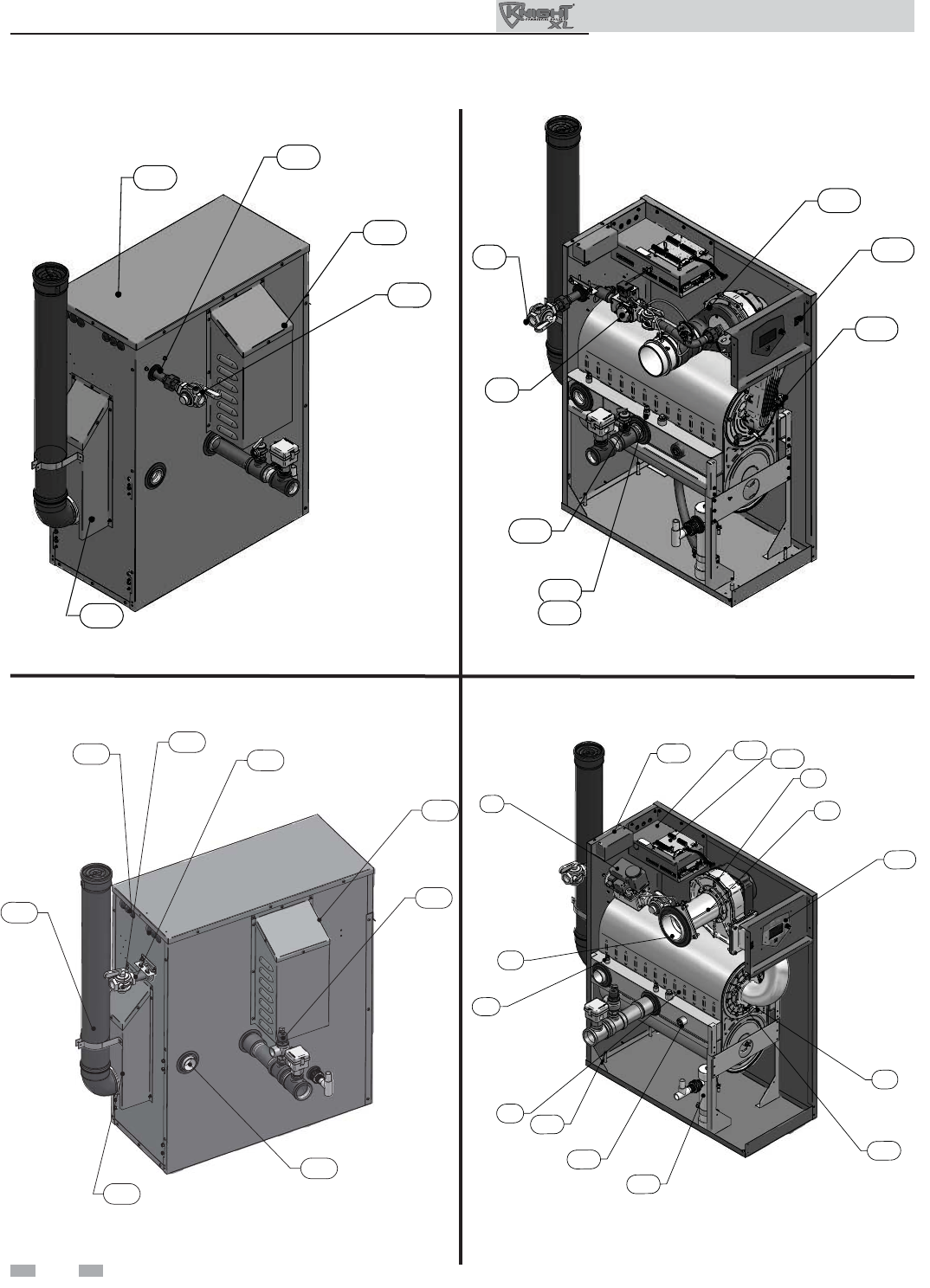
The Outdoor Knight XL - How it works...
1. Stainless steel heat exchanger
Allows system water to fl ow through specially designed
coils for maximum heat transfer, while providing protection
against fl ue gas corrosion. The coils are encased in a jacket that
contains the combustion process.
2. Combustion chamber access cover
Allows access to the combustion side of the heat exchanger
coils.
3. Blower
The blower pulls in air and gas through the venturi (item 5).
Air and gas mix inside the blower and are pushed into the
burner, where they burn inside the combustion chamber.
4. Gas valve
The gas valve senses the negative pressure created by the
blower, allowing gas to fl ow only if the gas valve is powered and
combustion air is fl owing.
5. Venturi
The venturi controls air and gas fl ow into the burner.
6. Flue gas sensor (limit rated - not shown)
This sensor monitors the fl ue gas exit temperature. The
control module will modulate and shut down the boiler if the
fl ue gas temperature gets too hot. This protects the fl ue pipe from
overheating.
7. Boiler outlet temperature sensor (housed with the
high limit sensor)
This sensor monitors boiler outlet water temperature (system
supply). If selected as the controlling sensor, the control
module adjusts boiler fi ring rate so the outlet temperature is
correct.
8. Boiler inlet temperature sensor
This sensor monitors return water temperature (system
return). If selected as the controlling sensor, the control
module adjusts the boiler fi ring rate so the inlet temperature is
correct.
9. Temperature and pressure gauge (fi eld installed, not
shown)
Monitors the outlet temperature of the boiler as well as the
system water pressure.
10. Electronic LCD display
The electronic display consists of 4 buttons, a navigation dial
and a multiple line liquid crystal display.
11. Flue pipe assembly
Factory-supplied components for complete venting
system.
12. Burner (not shown)
Made with metal fi ber and stainless steel construction, the
burner uses pre-mixed air and gas and provides a wide range of
fi ring rates.
13. Water outlet (system supply)
A 1-1/2" or 2" NPT (depending on the model) water
connection that supplies hot water to the system.
14. Water inlet (system return)
A 1-1/2" or 2" NPT (depending on the model) water connection
that returns water from the system to the heat exchanger.
15. Gas connection pipe
Threaded pipe connection of 1". This pipe should be connected
to the incoming gas supply for the purpose of delivering gas to
the boiler.
16. SMART SYSTEM Control Module
The SMART SYSTEM Control responds to internal and
external signals and controls the blower, gas valve, and pumps
to meet the heating demand.
17. Manual air vent
Designed to remove trapped air from the heat exchanger
coils.
18. Air intake
Provides combustion air to the appliance.
19. Air Intake Cover
Provides protection from outdoor elements.
20. High voltage junction box
The junction box contains the connection points for the line
voltage power and all pumps.
21. Boiler drain port
Location from which the heat exchanger can be drained.
22. Low voltage connection board
The connection board is used to connect external low voltage
devices.
23. Low voltage wiring connections (plugs)
Conduit connection points for the low voltage connection
board.
24. Condensate drain connection
Connects the condensate drain line to a 1/2” PVC union.
25. Access cover - front
Provides access to the gas train and the heat exchanger.
26. Ignition electrode
Provides direct spark for igniting the burner.
27. Flame inspection window
The quartz glass window provides a view of the burner surface
and fl ame.
28. Gas shutoff valve
Manual valve used to isolate the gas valve from the gas supply.
29. Relief valve
Protects the heat exchanger from an over pressure condition.
The relief valve provided with the unit is set at 50 PSI.
30. Flame sensor
Used by the control module to detect the presence of burner
fl ame.
31. Line voltage wiring connections (knockouts)
Conduit connection points for the high voltage junction box.
32. Top panel
Removable panel to gain access to the internal components.
33. Power switch
Turns 120 VAC ON/OFF to the boiler.
34. Leveling legs
Used to allow the heat exchanger to be leveled. This is needed
for the proper draining of the condensate from the combustion
chamber.
35. Air shroud (Model 501 only)
The air shroud controls air and gas fl ow into the burner.
36. Air pressure switch
The air pressure switch detects blocked fl ue/inlet conditions.
break the control circuit, shutting the boiler down.
37. Pump relay board
The pump relay board is used to connect the boiler, system and
DHW pumps.
38. Transformer (not shown)
The transformer provides 24V power to the integrated control.
39. High limit sensor (housed with the outlet temperature
sensor)
Device that monitors the outlet water temperature. If the
temperature exceeds its setting, the integrated control will break
the control circuit, shutting the boiler down.
40. Over-temp switch (located underneath vent cover -
not shown)
An electrical switch designed to shut down boiler operation in
the event the outer back of the heat exchanger, directly above the
fl ue connection exceeds 604°F (318°C). This is a one time
switch and could warrant a heat exchanger replacement. Check
the integrity of the rear refractory at the back of the upper coil if
the switch opens.
41. Vent Cover
Covers Over-temp switch and fl ue collar with fl ue sensor.
42. Flow switch
The fl ow switch is a safety device that ensures fl ow through
the heat exchanger during operation. This appliance is low
mass and should never be operated without fl ow. The fl ow
switch makes contact when fl ow is detected and allows the unit
to operate. If fl ow is discontinued during operation for any
reason the fl ow switch will break the control circuit and the
unit wll shut down.
Outdoor Knight XL Installation & Operation Manual
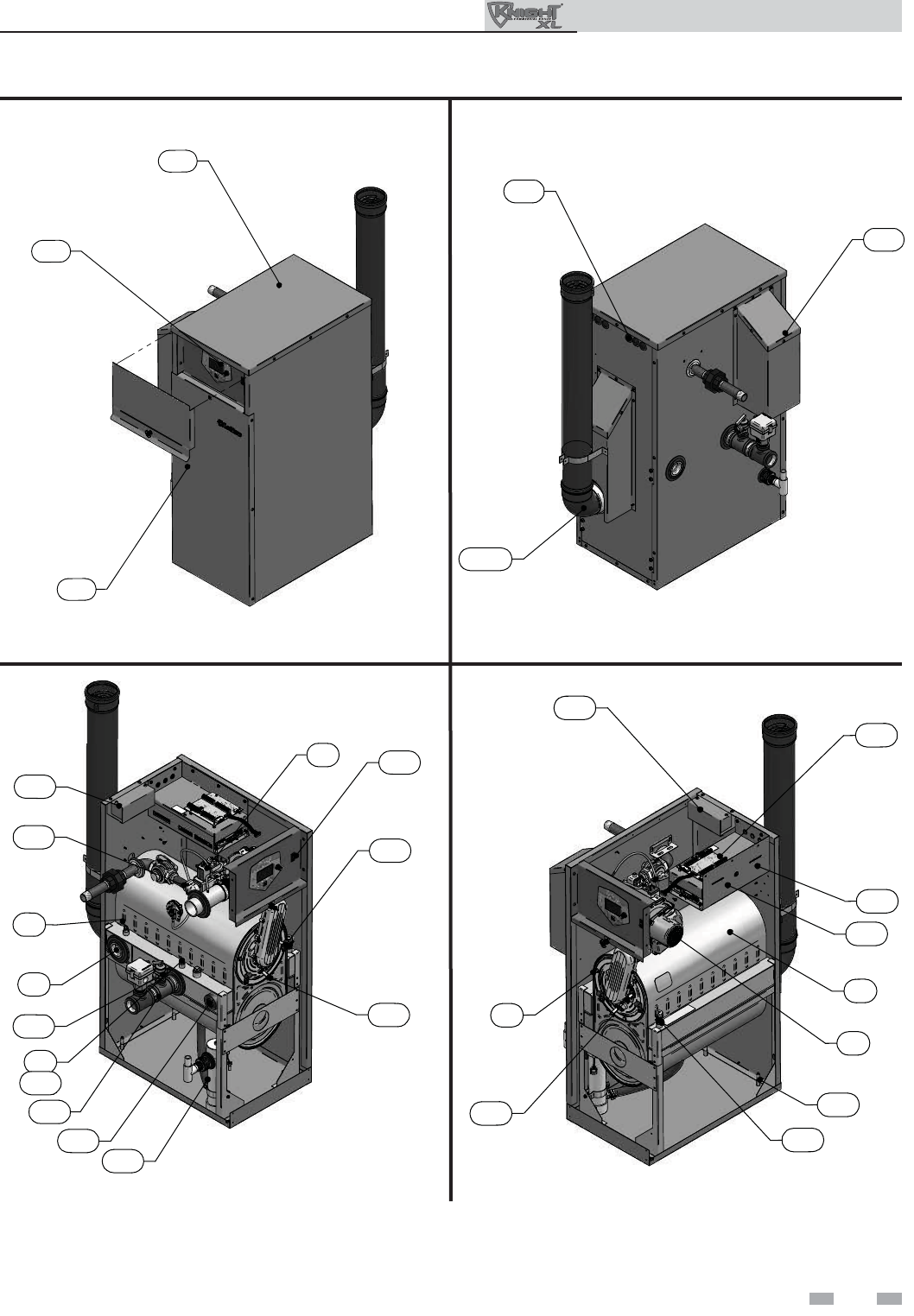
Front View - Model 400
30
26
20
36
8
7
21
24
4
4
39
13
IMG00406
39
33
Left Side (inside unit) - Model 400
20
22
37
16
34
17
27
2
1
3
IMG00407
Right Side (inside unit) - Model 400
Rear View - Model 400
5
Model 400
25
32
10
IMG00405
19
31
11
IMG00404
The Outdoor Knight XL - How it works... (continued)
Outdoor Knight XL Installation & Operation Manual
6
19
28
15
IMG00408
32
41
Rear View - Model 501
18
29
14
15
23 31
IMG00323
41
11
Rear View - Models 601 - 801 Left Side (inside unit) - Models 601 - 801
Left Side (inside unit) - Model 501
Model 501
Models 601 - 801
35
4
IMG00409
33
15
29
17
7
39
IMG00324
4
8
1
34
21
24
30
2
10
5
3
22
16
20
IMG00324
18
The Outdoor Knight XL - How it works...
Outdoor Knight XL Installation & Operation Manual
7
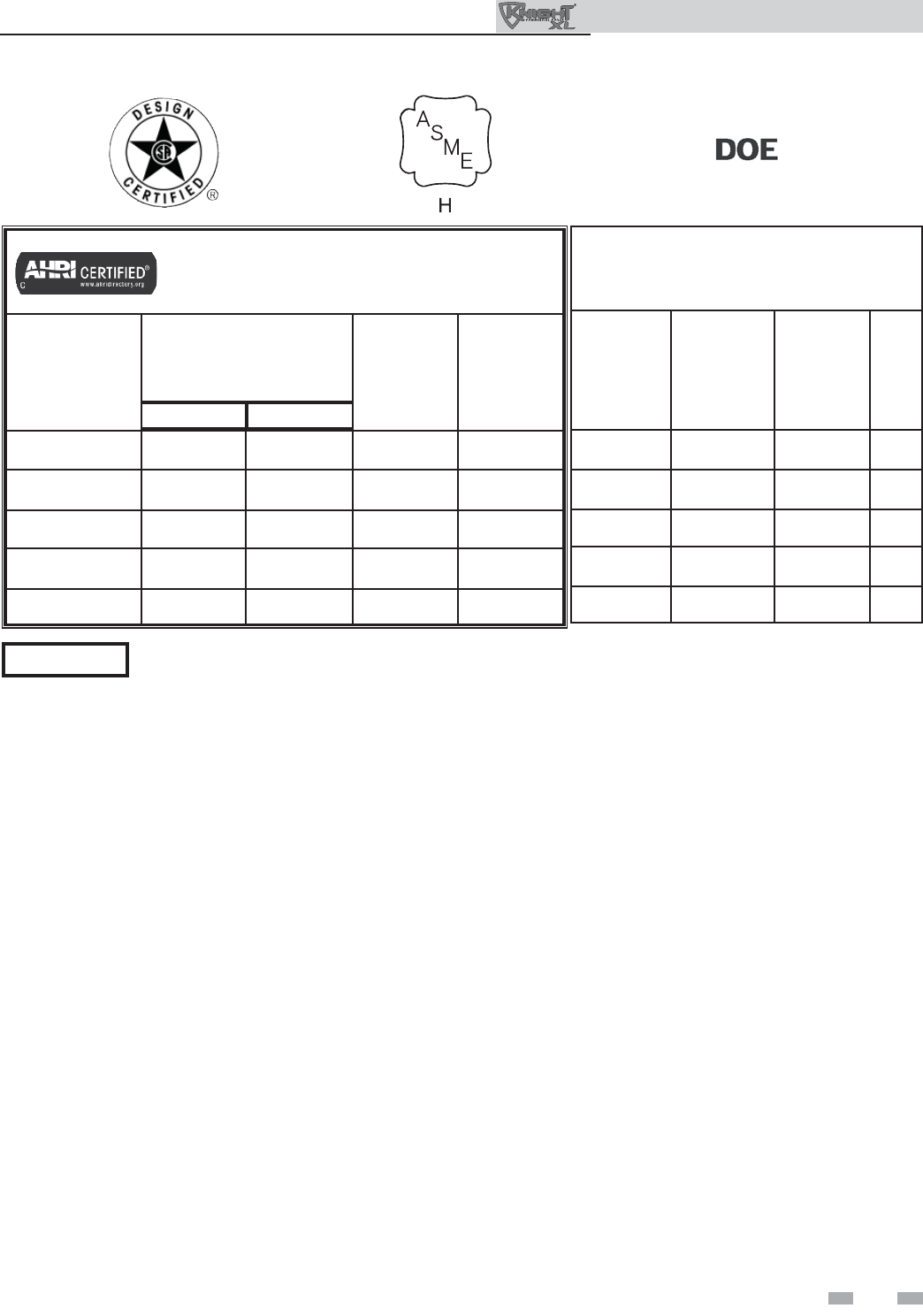
Ratings
Notes:
1. The ratings are based on standard test procedures prescribed by the United States Department of Energy.
2. Net AHRI ratings are based on net installed radiation of suffi cient quantity for the requirements of the building and nothing
need be added for normal piping and pickup. Ratings are based on a piping and pickup allowance of 1.15.
3. Standard Outdoor Knight XL boilers are equipped to operate from sea level to 4,500 feet only with no adjustments. The boiler
will de-rate by 4% for each 1,000 feet above sea level up to 4,500 feet.
4. Ratings have been confi rmed by the Hydronics Section of AHRI.
5. Outdoor Knight XL boilers comply with the requirements of CSD-1 Section CW-400 requirements as a temperature operation
control. The manual reset high limit provided with the Outdoor Knight XL is listed to UL353.
Maximum allowed working pressure is located on the rating plate.
NOTICE
Outdoor Knight XL Boiler
AHRI Rating
Model Number
Note: Change “N” to
“L” for L.P. gas models.
Input
MBH
(Note 4)
Min Max
Gross
Output
MBH
(Note 1)
Net
AHRI
Ratings
Water,
MBH
(Note 2)
OKN400 80 399 370 322
OKN501 100 500 463 402
OKN601 120 600 566 493
OKN701 140 700 658 572
OKN801 160 800 748 651
Other Specifi cations
Boiler Water
Content
Gallons
Water
Connections Gas
Connections Air Size
3.4 1-1/2" 1" 4"
4.2 1-1/2" 1" 4"
4.2 2" 1" 4"
5.0 2" 1" 4"
5.7 2" 1" 4"
Outdoor Knight XL Installation & Operation Manual
8
The Outdoor Knight XL gas manifold
and controls met safe lighting and other
performance criteria when the boiler
underwent tests specifi ed in ANSI Z21.13
– latest edition.
Do not install the unit under a deck.
Do not install the unit in a well, stairwell,
alcove, courtyard or other recessed area.
Do not install outdoor units on stack
frames. Failure to comply with the above
may result in severe personal injury, death
or substantial property damage.
Installation must comply with:
• Local, state, provincial, and national codes, laws,
regulations, and ordinances.
• National Fuel Gas Code, ANSI Z223.1 – latest edition.
• Standard for Controls and Safety Devices for Automatically
Fired Boilers, ANSI/ASME CSD-1, when required.
• National Electrical Code.
Before locating the boiler, check:
1. Check for nearby connection to:
• System water piping
• Gas supply piping
• Electrical power
2. - Keep venting areas free of obstructions.
- Keep area clean and free of combustible and fl ammable
materials.
- To avoid a blocked air inlet or blocked fl ue condition,
keep the outdoor air inlet and fl ue outlet clear or leaves,
debris, etc.
4. If a new boiler will replace an existing boiler, check for
and correct system problems, such as:
• System leaks causing oxygen corrosion or heat exchanger
cracks from hard water deposits.
• Incorrectly-sized expansion tank.
• This unit is not intended for installations where
temperatures may reach below 32°F (0°C). Exposure to
freezing temperatures will cause the system and boiler
to freeze and leak.
WARNING
NOTICE
1 Determine boiler location
Do not install outdoor models directly on
the ground. You must install the outdoor
unit on a level concrete, brick, block, or
pressure-treated wood platform.
Do not locate unit so that high winds
can defl ect off of adjacent walls, buildings
or shrubbery causing recirculation.
Recirculation of fl ue products may cause
operational problems, bad combustion or
damage to controls. Locate unit at least
3 feet (0.91m) from any wall or vertical
surface to prevent wind conditions from
affecting performance.
CAUTION
CAUTION
3. Check area around the boiler. Remove any combustible
materials, gasoline and other fl ammable liquids.
Outdoor Knight XL Installation & Operation Manual
Outdoor models must be installed outdoors
only and must use the outdoor vent
assembly supplied by the manufacturer.
Personal injury or product damage may
result if any other venting is used or if an
outdoor model is used indoors. All covers,
doors and jacket panels must be properly
installed to ensure proper operation and
prevent a hazardous condition.
WARNING
WARNING
The unit must not be installed in an area
that is enclosed by walls or a fence that
will block free wind movement around
the appliance. Free movement of wind
around the outdoor unit is required
to carry away the fl ue products and
provide combustion air. The fl ue outlet/
combustion air inlet of an outdoor unit
must not be installed closer than 10 feet
from an inside corner of an L-shaped
structure. Walls or enclosed fencing may
cause eddy currents which can recirculate
the fl ue products into the combustion
air inlet. Recirculation of fl ue products
may cause operational problems, bad
combustion or non-warrantable damage
to controls.
Locate the unit at least 3 feet (0.91m)
outside any overhang.
CAUTION
CAUTION Do not install in locations where rain
from building runoff drains will spill onto
the unit.
Do not locate the unit so that water
from sprinklers may spray directly onto
it. Water may damage controls or other
electrical components.
Failure to keep boiler area clear and free
of combustible materials, gasoline, and
other fl ammable liquids and vapors can
result in severe personal injury, death, or
substantial property damage.
WARNING
This product contains a condensate
management and disposal system that
may be subject to freezing if exposed
to sustained temperatures below 32°F.
Precautions should be taken to protect the
condensate trap and drain lines during
extended periods of outdoor temperatures
below 32°F.
1 Determine boiler location (continued)
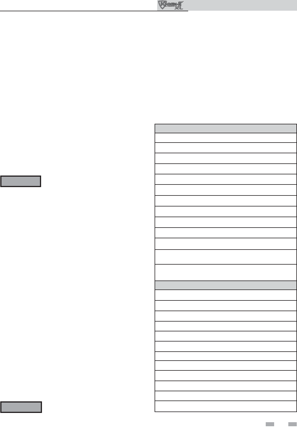
Products to avoid:
Spray cans containing chloro/fl uorocarbons
Permanent wave solutions
Chlorinated waxes/cleaners
Chlorine-based swimming pool chemicals
Calcium chloride used for thawing
Sodium chloride used for water softening
Refrigerant leaks
Paint or varnish removers
Hydrochloric acid/muriatic acid
Cements and glues
Antistatic fabric softeners used in clothes dryers
Chlorine-type bleaches, detergents, and cleaning solvents
found in household laundry rooms
Adhesives used to fasten building products and other
similar products
Areas likely to have contaminants
Dry cleaning/laundry areas and establishments
Swimming pools
Metal fabrication plants
Beauty shops
Refrigeration repair shops
Photo processing plants
Auto body shops
Plastic manufacturing plants
Furniture refi nishing areas and establishments
New building construction
Remodeling areas
Garages with workshops
Table 1A Corrosive Contaminants and Sources
Provide clearances:
Clearances from combustible materials
1. Hot water pipes—at least 1/4" (6 mm) from combustible
materials.
2. Jacket—minimum of 0" from right side and 14" from rear
side for proximity from combustible materials.
3. Vent—minimum of 1" from combustible materials.
Clearances for service access
1. If you do not provide the minimum clearances shown, it
may not be possible to service the boiler without removing
it from the space.
Do not install the boiler on carpeting even
if foundation is used. Fire can result,
causing severe personal injury, death, or
substantial property damage.
Flooring and foundation
Flooring
The Outdoor Knight XL is approved for installation on
combustible fl ooring.
WARNING
Prevent combustion air contamination
Do not install unit in locations that can allow contamination
of combustion air. Refer to Table 1A for products and areas
which may cause contaminated combustion air.
Under no circumstances is the manufacturer to be held
responsible for water damage in connection with this
appliance, or any of its components. If fl ooding is possible,
elevate the boiler suffi ciently to prevent water from reaching
the boiler.
Recommended service clearances
Front: 30" (762mm)
Top: 24" (610mm)
Left side: 24" (610mm)
Rear: 24" (610mm)
Outdoor Knight XL Installation & Operation Manual
Outdoor vent / air intake location:
The fl ue products discharged from the
fl ue outlet on the outdoor vent may be
very hot. Avoid touching or making other
direct contact with the fl ue gases or the
vent termination. These components are
hot and direct contact can result in burns.
WARNING
To prevent recirculation of the fl ue products into the
combustion air inlet, follow all instructions in this section.
Flue gas condensate can condense on exterior walls or on the
vent. Some discoloration or exterior building or unit surfaces
can be expected. Adjacent brick or masonry surfaces should
be protected with a rust resistant sheet metal plate.
Maintain a minimum of 24" clearance to the air inlet.
Locate the outdoor vent termination at least 48" (1.22m)
below and 48" (1.22m) horizontally from any window, door,
walkway or gravity air intake.
Locate the unit at least 10 feet (3.05m) away from any forced
inlet.
Multiple unit outdoor installations require 24" (1.22m)
clearance between each vent termination.
Clearances around outdoor installations can change with
time. Do not allow the growth of trees, shrubs or other plants
to obstruct the proper operation of the outdoor vent system.
9
10
2 Prepare boiler
Install fl ue pipe assembly
This unit is provided with all of the necessary venting
components. All components must be installed prior to
operation.
1. Locate all venting components from the installation kit
and carton.
2. Before connecting the vent pipe sections or components,
verify that the gasket is seated evenly inside the groove in
the female end of the elbow and fl ue adaptor (FIG. 2-2).
3. Remove the provided screws from the vent cover and use
them to install the vent strap (FIG. 2-2).
4. Insert the elbow into fl ue adaptor (FIG. 2-2).
Outdoor Knight XL Installation & Operation Manual
Do NOT use grease or other lubricant
on the vent seals. Only water may be
used for this purpose. Grease or other
lubricant can make the seal brittle or
cause tearing of the seal surface which
can result in fl ue gas leakage.
CAUTION
5. Slide the vent pipe through the wall strap and insert it
into the elbow (FIG. 2-2).
6. Install the bird screen into the top of the vent.
Figure 2-2 Install fl ue pipe assembly - Models 400 -
601
FLUE
ADAPTER
ELBOW
VENT PIPE
BIRD SCREEN
WALL STRAP
AND SCREWS
IMG00444
NOTE: VERIFY THAT GASKET IS SEATED EVENLY
INSIDE THE GROOVE IN ELBOW AND ADAPTER
Models 400 - 601
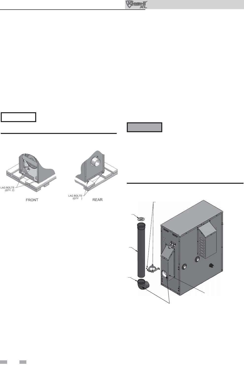
Remove boiler from wood pallet
1. After removing the outer shipping carton from the
boiler, remove the parts box.
2. Remove the front door to access the lag bolts in front
of the unit (FIG. 2-1).
3. To remove the boiler from the pallet (after removing
the front door):
a. Remove the two lag bolts from the wood pallet
inside the boiler (FIG. 2-1).
b. Detach the boiler from the lag bolts in the rear of the
unit, see FIG. 2-1.
Do not drop the boiler or bump the
jacket on the fl oor or pallet. Damage to
the boiler can result.
. 2
Figure 2-1 Boiler Mounted on Shipping Pallet
NOTICE
2 Prepare boiler (continued)
Outdoor Knight XL Installation & Operation Manual
Do NOT use grease or other lubricant on the
vent seals. Only water may be used for this
purpose. Grease or other lubricant can make
the seal brittle or cause tearing of the seal
surface which can result in fl ue gas leakage.
CAUTION
11
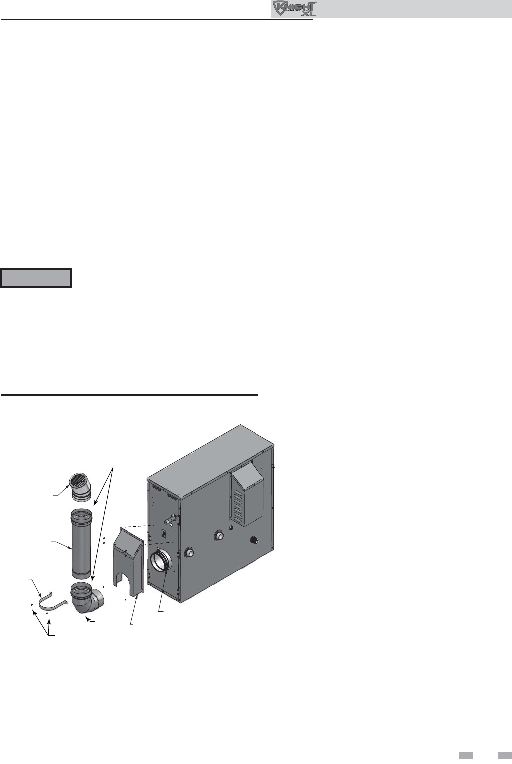
Models 701 - 801
Figure 2-3 Install fl ue pipe assembly - Models 701 - 801
CLAMP
VENT COVER
WALL STRAP
SCREWS
WALL
STRAP
ELBOW
VENT PIPE
VENT
TERMINATION
IMG00446
NOTE: VERIFY THAT GASKET IS SEATED EVENLY
INSIDE THE GROOVE IN ELBOW AND ADAPTER
1. Locate all venting components from the installation kit and
carton.
2. Before connecting the vent pipe sections or components,
verify that the gasket is seated evenly inside the groove
in the female end of the elbow and fl ue adapter
(FIG. 2-3).
3. Remove the vent cover from the back of the unit as shown in
FIG. 2-3.
4. Insert the elbow into the fl ue adapter and tighten the clamp
using a 5/16" nut driver (FIG. 2-3).
5. Re-install the vent cover removed in Step 3.
6. Remove the provided screws from the vent cover and use
them to install the wall strap (FIG. 2-3).
7. Slide the vent pipe through the wall strap and insert it into the
elbow. Tighten the clamp (FIG. 2-3).
8. Install the termination into the top of the vent and tighten the
clamp.
12
Outdoor Knight XL Installation & Operation Manual
For a boiler already installed, you must
turn off gas supply, turn off power and
allow boiler to cool before proceeding.
You must also completely test the boiler
after conversion to verify performance
as described under Start-up, Section 10
of this manual. Failure to comply could
result in severe personal injury, death, or
substantial property damage.
For the 400 Model you must install a
propane orifi ce to operate the Outdoor
Knight XL on propane gas. Verify when
installing that the orifi ce size marking
matches boiler size (Model 400 - 8.0 LP
orifi ce stamping).
Models 501 - 801 do not require an orifi ce
installation for propane operation, but
they will require a valve adjustment.
Gas conversions
WARNING
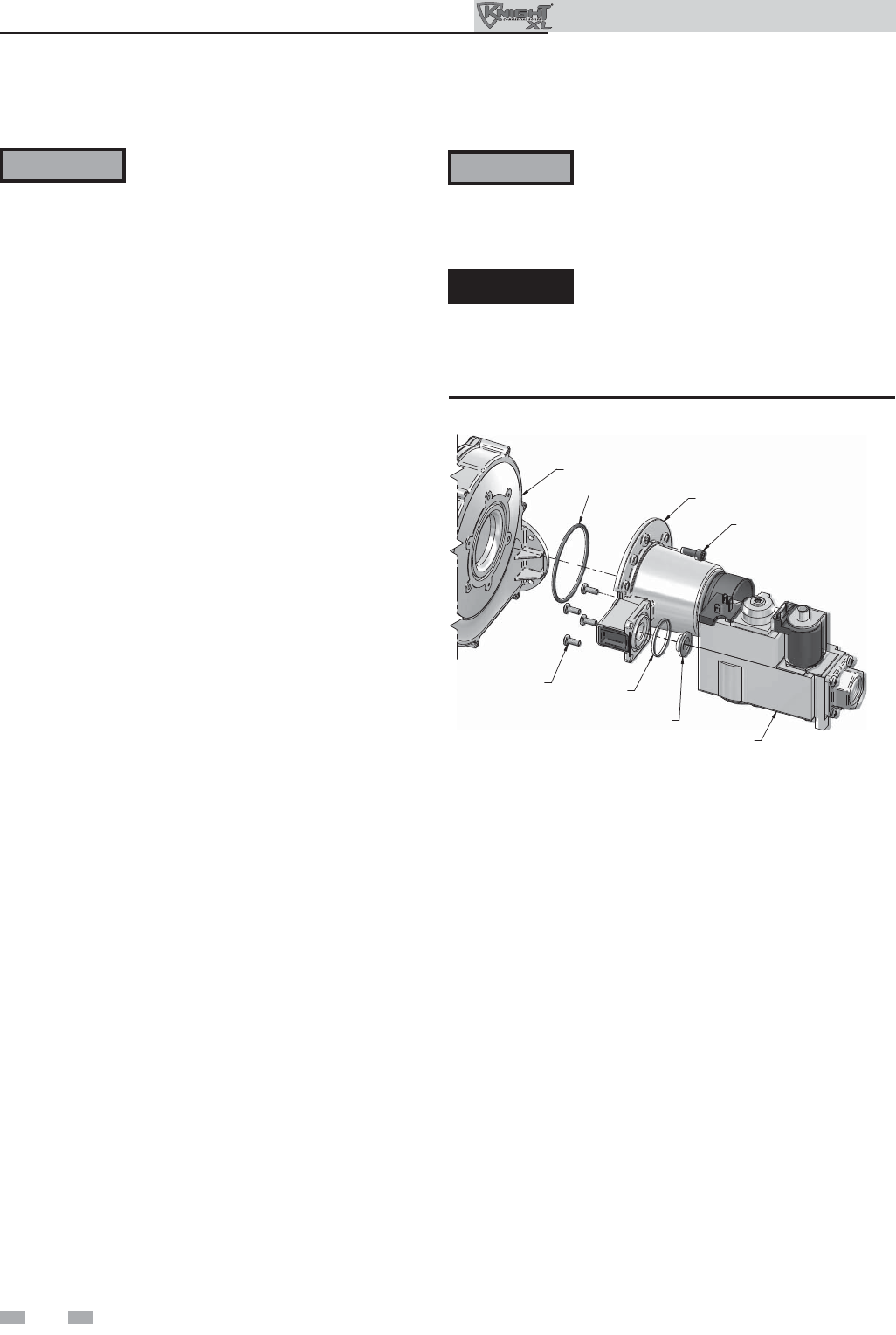
Model 400
1. Remove the top and front access covers from the unit
(tools required for removal).
2. Remove the three screws securing the venturi to the
blower. Note: When separating the venturi from the
blower, take care not to damage the O-ring inside the
blower (FIG. 2-4).
3. Remove the four star-drive screws securing the gas valve
to the venturi (FIG. 2-4).
4. Locate the propane orifi ce disk from the conversion kit
bag.Verify that the stamping on the orifi ce disk matches
the boiler size (Model 400 - 8.0 LP orifi ce stamping).
5. Remove the existing orifi ce from the O-ring in the side of
the gas valve and replace it with the orifi ce from the kit.
Position and secure the orifi ce in the valve as shown in
FIG. 2-4.
6. Reposition the gas valve against the venturi and replace
the star-drive screws (FIG. 2-4) securing the valve to the
venturi.
7. Inspect the O-ring inside the blower. Handle the O-ring
with care, do not damage. Reposition the venturi against
the blower and replace the screws securing the venturi to
the blower (FIG. 2-4).
8. After installation is complete, attach the propane
conversion label (in the conversion kit bag) next to the
boiler rating plate. Attach the LP caution label (in the
conversion kit bag) to the left side of the unit in the lower
left corner.
9. Replace the top and front access covers.
DANGER Model 400: Inspect the O-ring when the
blower is disassembled. The O-ring must
be in good condition and must be installed.
Failure to comply will cause a gas leak,
resulting in severe personal injury or death.
WARNING After converting to LP, check combustion
per the Start-up procedure in Section 10
of this manual. Failure to check and verify
combustion could result in severe personal
injury, death, or substantial property damage.
BLOWER
O-RING VENTURI
SCREWS
QTY. 3
GAS VALVE
BRASS ORIFICE
O-RING
SCREWS
QTY. 4
Figure 2-4 Installing Propane Orifi ce - Model 400
2 Prepare boiler

13
SCREWDRIVER
SLOT
LOWER
RAISE
Figure 2-7 Leveling Legs on the Boiler
Leveling the boiler
1. Set the boiler in place and check level.
a) Adjust legs if necessary to level boiler, see FIG. 2-7
below.
ALLEN WRENCH
ADJUSTMENT SCREW
Figure 2-5 Gas Valve Adjustment - Model 501
Model 501
1. Remove the top access cover from the unit (Philips Head
screwdriver required for removal).
2. Turn the adjustment screw on the gas valve clockwise until
it stops. Then turn the adjustment screw counterclockwise
four and three quarter (4 3/4) turns (see FIG. 2-5).
3. Use a combustion analyzer to verify CO2 is within the range
of 9.6 – 10.5%. If not, adjust the screw counterclockwise
incrementally to raise CO2 and clockwise to lower CO2
(FIG. 2-5).
4. After adjustment is complete, attach the propane conversion
label (in the conversion kit bag) next to the boiler rating
plate. Attach the LP caution label (in the conversion kit bag)
to the left side of the unit in the lower left corner.
5. Replace the top access cover.
COVER
ALLEN WRENCH
ADJUSTMENT SCREW
Figure 2-6 Gas Valve Adjustment - Models 601 - 801
Models 601 - 801
1. Remove the top access cover from the unit (Philips Head
screwdriver required for removal).
2. Remove the cover on top of the gas valve (FIG. 2-6).
3. Turn the adjustment screw on top of the gas valve clockwise
one and three quarter (1 3/4) turns on the 601 Model, one
and a half (1 1/2) turns on the 701 Model, and one turn on
the 801 Model (see FIG. 2-6).
4. Use a combustion analyzer to verify CO2 is within the range
of 9.6 – 10.5%. If not, adjust the screw counterclockwise
incrementally to raise CO2 and clockwise to lower CO2
(FIG. 2-6).
5. After adjustment is complete, attach the propane conversion
label (in the conversion kit bag) next to the boiler rating
plate. Attach the LP caution label (in the conversion kit
bag) to the left side of the unit in the lower left corner.
6. Replace the gas valve cover along with the top access cover.
WARNING After converting to LP, check combustion
per the Start-up procedure in Section 10
of this manual. Failure to check and verify
combustion could result in severe personal
injury, death, or substantial property
damage.
WARNING After converting to LP, check combustion
per the Start-up procedure in Section
10 of this manual. Failure to check and
verify combustion could result in severe
personal injury, death, or substantial
property damage.
2 Prepare boiler (continued)
Outdoor Knight XL Installation & Operation Manual
14
Outdoor Knight XL Installation & Operation Manual
3 Hydronic piping
System water piping methods
The Outdoor Knight XL is designed to function in a closed
loop pressurized system not less than 12 psi (83 kPa). A
temperature and pressure gauge is included to monitor
system pressure and outlet temperature and should be
located on the boiler outlet.
It is important to note that the boiler has a minimal amount
of pressure drop which must be fi gured in when sizing
the circulators. Each boiler installation must have an air
elimination device, which will remove air from the system.
Install the boiler so the gas ignition system components
are protected from water (dripping, spraying, etc.) during
appliance operation or basic service of circulator replacement,
valves, and others.
Observe a minimum of 1/4 inch (6 mm) clearance around all
un-insulated hot water pipes when openings around the pipes
are not protected by non-combustible materials.
Low water cutoff device
On a boiler installed above radiation level, some states and
local codes require a low water cutoff device at the time of
installation.
Chilled water system
If the boiler supplies hot water to heating coils in air handler
units, fl ow control valves or other devices must be installed to
prevent gravity circulation of heater water in the coils during
the cooling cycle. A chilled water medium must be piped in
parallel with the heater.
Freeze protection
Freeze protection for new or existing systems must use
glycol that is specially formulated for this purpose. This
includes inhibitors, which prevent the glycol from attacking
the metallic system components. Make certain to check that
the system fl uid is correct for the glycol concentration and
inhibitor level. The system should be tested at least once
a year and as recommended by the producer of the glycol
solution. Allowance should be made for the expansion of the
glycol solution in the system piping.
General piping information
Basic steps are listed below along with illustrations on the
following pages (FIG.’s 3-7 through 3-11), which will guide
you through the installation of the Outdoor Knight XL
(reference FIG.’s 3-4A and 3-4B).
1. Connect the system return marked “Inlet”.
2. Connect the system supply marked “Outlet”.
3. Install purge and balance valve or shutoff valve and drain
on system return to purge air out of each zone.
4. Install a backfl ow preventer on the cold feed make-up
water line.
5. Install a pressure reducing valve on the cold feed make-up
water line, (15 psi (103 kPa) nominal). Check temperature
and pressure gauge (shipped separately), which should
read a minimum pressure of 12 psi (83 kPa).
6. Consult the factory for a pump and/or pump cover. If a
fi eld-supplied pump is used, install per the manufacturer’s
specifi cations in regard to indoor or outdoor location. An
outdoor rated pump is recommended.
7. Install a circulator as shown on the piping diagrams in this
section. Make sure the circulator is properly sized for the
system and friction loss.
8. Install an expansion tank on the system supply. Consult the
tank manufacturer’s instruction for specifi c information
relating to tank installation. Size the expansion tank for the
required system volume and capacity.
9. Install an air elimination device on the system supply.
10. Install a drain valve at the lowest point of the system.
Note: The boiler cannot be drained completely of water
without purging the unit with an air pressure of 15 psi
(103 kPa).
11. This appliance is supplied with a relief valve sized in
accordance with ASME Boiler and Pressure Vessel Code,
Section IV (“Heating Boilers”). Pipe the discharge of the
safety relief valve to prevent injury in the event of pressure
relief. Pipe the discharge to a drain. Provide piping that is
the same size as the safety relief valve outlet. Never block
the outlet of the safety relief valve.
See the piping illustrations included in this section, FIG.’s
3-7 and 3-11 for suggested guidelines in piping the Outdoor
Knight XL.
Please note that these illustrations are
meant to show system piping concept only,
the installer is responsible for all equipment
and detailing required by local codes.
Use only inhibited propylene glycol
solutions, which are specifi cally formulated
for hydronic systems. Ethylene glycol is
toxic and can attack gaskets and seals used
in hydronic systems.
WARNING
NOTICE
WARNING The relief valve, tee and any other necessary
fi ttings are shipped in the install kit with the
boiler and are to be fi eld installed (FIG.’s
3-1 and 3-2).
12. On any pre-existing system, it is good practice to install
a fi eld supplied strainer to prevent damage to the heat
exchanger.
15
RELIEF VALVE
FLOW SWITCH
PADDLE
TEMPERATURE &
PRESSURE GAUGE
TEE WITH FITTING
(FIELD PROVIDED)
CLOSE NIPPLE
(FIELD PROVIDED)
TEE WITH 1" FITTING
ON TOP
CLOSE NIPPLE
TEE WITH 3/4"
FITTING ON TOP
IMG00389
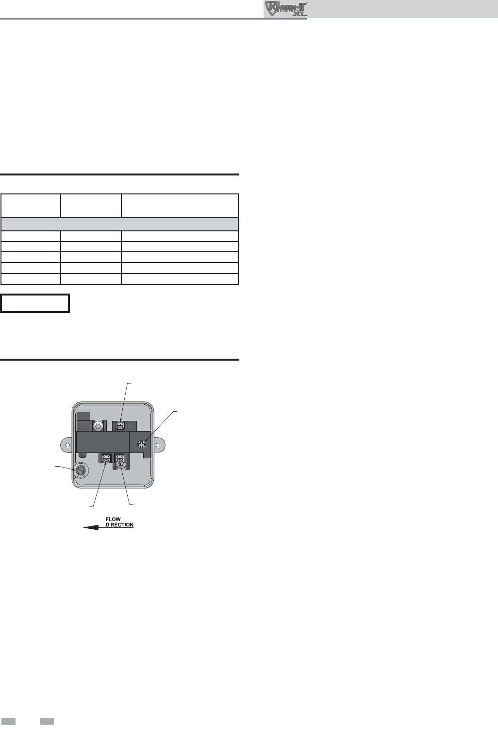
NOTICE Be sure to install the fl ow switch so
that the arrow on the fl ow switch is
pointing in the direction of the fl ow
(see FIG. 3-3).
Figure 3-2 Flow Switch, Relief Valve and Temperature and
Pressure Gauge Installation_Models 601 - 801
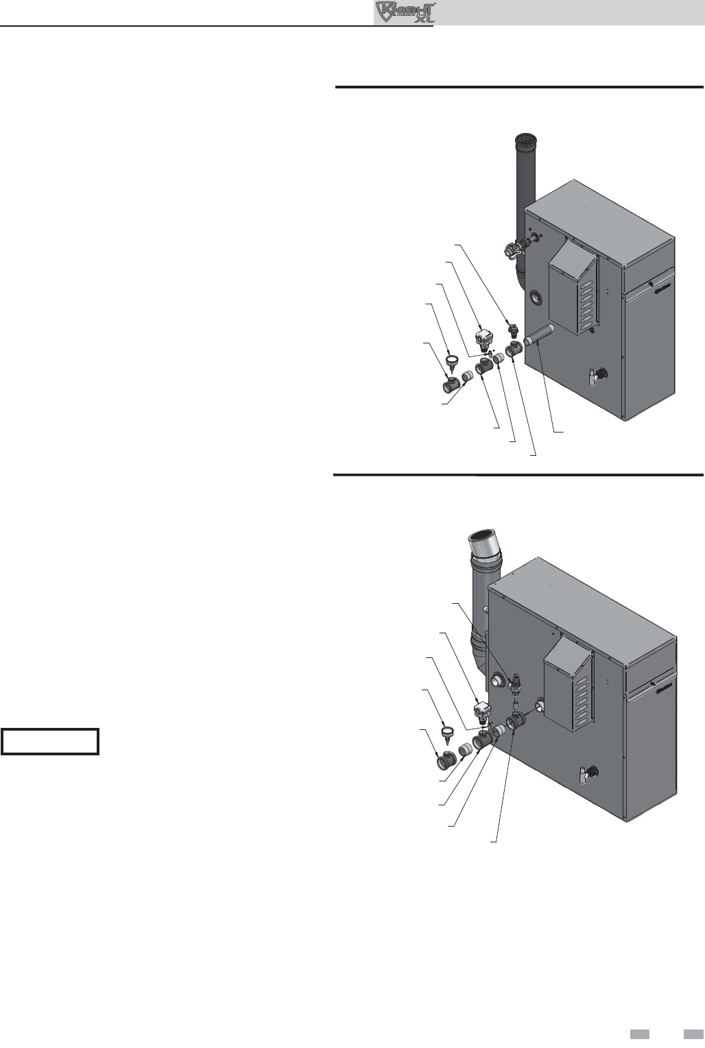
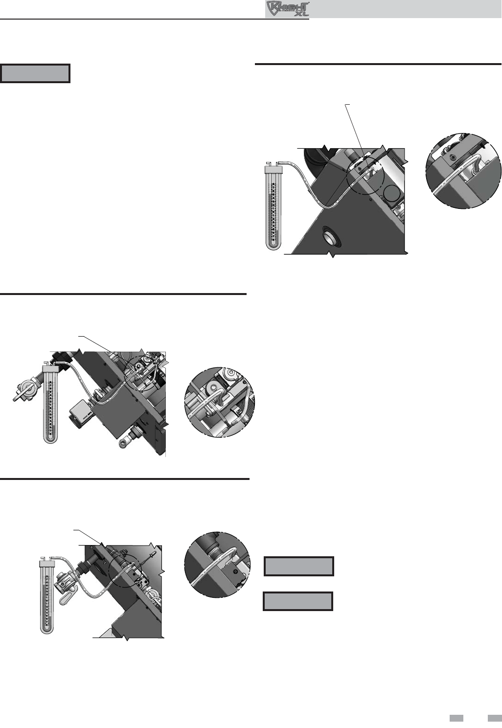
Flow switch, relief valve and temperature
and pressure gauge installation
Basic steps are listed below to guide you through the
installation of the fl ow switch, relief valve, and temperature
and pressure gauge provided with the unit.
1. For Models 400 - 501 install the close nipple on the
outlet connection of the heat exchanger. Install the tee
with the 3/4 inch fi tting positioned vertically and on
the top as shown in FIG. 3-1. For Models 601 - 801
install the tee directly to the outlet connection of the
heat exchanger with the 3/4 inch fi tting positioned
vertically and on the top (see FIG. 3-2).
2. For Models 701 - 801 install the 3/4 inch close nipple
in the tee. Install the relief valve on the 3/4 inch close
nipple (FIG. 3-2). For Models 400 - 601 install the
relief valve directly into the 3/4 inch fi tting on the tee
(FIG. 3-1).
3. Install the close nipple on the downstream side of
the relief valve tee (FIG. 3-1).
4. Install the tee with the 1 inch fi tting positioned
vertically and on the top (FIG. 3-1).
5. Attach paddle #3 to the fl ow switch per the
manufacturer’s instructions.
6. Install the assembled fl ow switch into the 1 inch fi tting
of the tee installed in Step 4 (see FIG. 3-1).
7. Install a fi eld provided close nipple on the downstream
side of the fl ow switch (see FIG.’s 3-1 and 3-2).
8. Install a fi eld provided tee with the gauge fi tting
positioned vertically and on the top (FIG.’s 3-1 and
3-2)
9. Install the temperature and pressure gauge provided
with the unit into the top fi tting of the tee (a bushing
may be necessary) installed in Step 8 (FIG.’s 3-1 and
3-2).
RELIEF VALVE
FLOW SWITCH
PADDLE
TEMPERATURE &
PRESSURE GAUGE
TEE WITH FITTING
ON TOP
(FIELD PROVIDED)
CLOSE NIPPLE
(FIELD PROVIDED)
TEE WITH 1" FITTING ON TOP
CLOSE NIPPLE
TEE WITH 3/4"
FITTING ON TOP
8' NIPPLE
(REQUIRED FOR MODELS 400 - 701)
IMG00390
Figure 3-1 Flow Switch, Relief Valve and Temperature and
Pressure Gauge Installation_Models 400 - 501
3 Hydronic piping (continued)
Outdoor Knight XL Installation & Operation Manual
16
Outdoor Knight XL Installation & Operation Manual
3 Hydronic piping
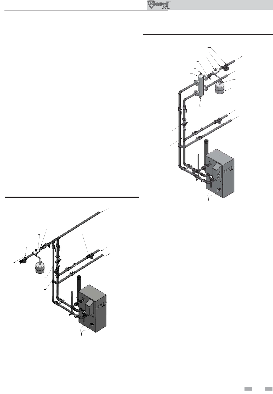
Figure 3-3 Flow Switch Adjustment
Flow switch adjustment
Refer to Table 3A for the proper setting of the sensitivity
screw. For reference, the position of the screw prior to setting
should be turned clockwise with a Phillips driver until it stops
(FIG. 3-3). Proceed to turn the screw counterclockwise the
amount of turns listed in Table 3A based on the model.
Consult the manufacturer’s instructions for wiring the fl ow
switch to your system.
NORMALLY
OPEN
SENSITIVITY
ADJUSTMENT
NORMALLY
CLOSED
COMMON
GROUND
NOTICE Turn the sensitivity screw clockwise to
increase the fl ow rate required to activate
the switch. Turn the sensitivity screw
counterclockwise to decrease the fl ow rate
required to activate the switch.
MODEL PADDLE SIZE SENSITIVITY SCREW
ADJUSTMENT
Note: Paddles are included with the fl ow switch.
400 #3 7½ turns
501 #3 5½ turns
601 #3 7¼ turns
701 #3 5¼ turns
801 #3 3¼ turns
Table 3A Paddle Size / Sensitivity Screw Adjustment
Near boiler piping components
1. Boiler system piping:
Boiler system piping MUST be sized per the pipe
requirements listed in Table 3B. Reducing the pipe size
can restrict the fl ow rate through the boiler, causing
inadvertent high limit shutdowns and poor system
performance. Flow rates are based on 20 feet (6 m) of
piping, 4 - 90° elbows, and 2 - fully ported ball valves.
2. Boiler system circulating pump:
(Field supplied.) The boiler circulating pump should be
based on 20 feet (6 m) of piping, 4 - 90° elbows, and
2 - fully ported ball valves.
3. Domestic hot water circulating pump:
(Field supplied.) The pump MUST be sized to meet
the specifi ed minimum fl ow requirements listed in
FIG.’s 3-5 and 3-6. Consult the indirect water heater
operating guide to determine fl ow characteristics for the
selected product used.
4. Variable speed boiler system circulator:
Outdoor Knight XL boilers are capable of controlling
a variable speed boiler system circulator. Variable speed
circulators MUST be sized to meet the specifi ed minimum
fl ow requirements listed in FIG.’s 3-5 and 3-6 on page 16
at full speed.
5. Boiler isolation valves:
Field supplied. Full port ball valves are required. Failure
to use full port ball valves could result in a restricted fl ow
rate through the boiler.
6. Check valves:
Field supplied. Check valves are recommended for
installation as shown in FIG.’s 3-7 through 3-11. Failure
to install check valves could result in a reverse fl ow
condition during pump(s) off cycle.
7. Domestic indirect hot water isolation valves:
Field supplied. Full port ball valves are required. Failure
to use full port ball valves could result in a restricted fl ow
rate through the boiler.
8. Anti-scald mixing valve:
Field supplied. An anti-scald mixing valve is
recommended when storing domestic hot water above
115°F (46°C).
9. Unions:
Field supplied. Recommended for unit serviceability.
10. Temperature and pressure gauge:
Factory supplied. The temperature and pressure gauge is
shipped loose. It is the responsibility of the contractor to
install the temperature and pressure gauge on the boiler
water outlet.
11. Pressure relief valve:
Factory supplied. The pressure relief valve is sized to
ASME specifi cations.
17
3 Hydronic piping (continued)
Near boiler piping connections
Y-STRAINER
(RECOMMENDED)
BOILER PUMP
INDIRECT
DOMESTIC
HOT WATER
TANK
TO FLOOR
DRAIN
TO
FROM
FROM
SYSTEM
TO
SYSTEM
DOMESTIC HOT
WATER PUMP
AIR SEPARATOR
SYSTEM SENSOR
IMG00413
SYSTEM PUMP
Figure 3-4A Near Boiler Piping w/Y-Strainer
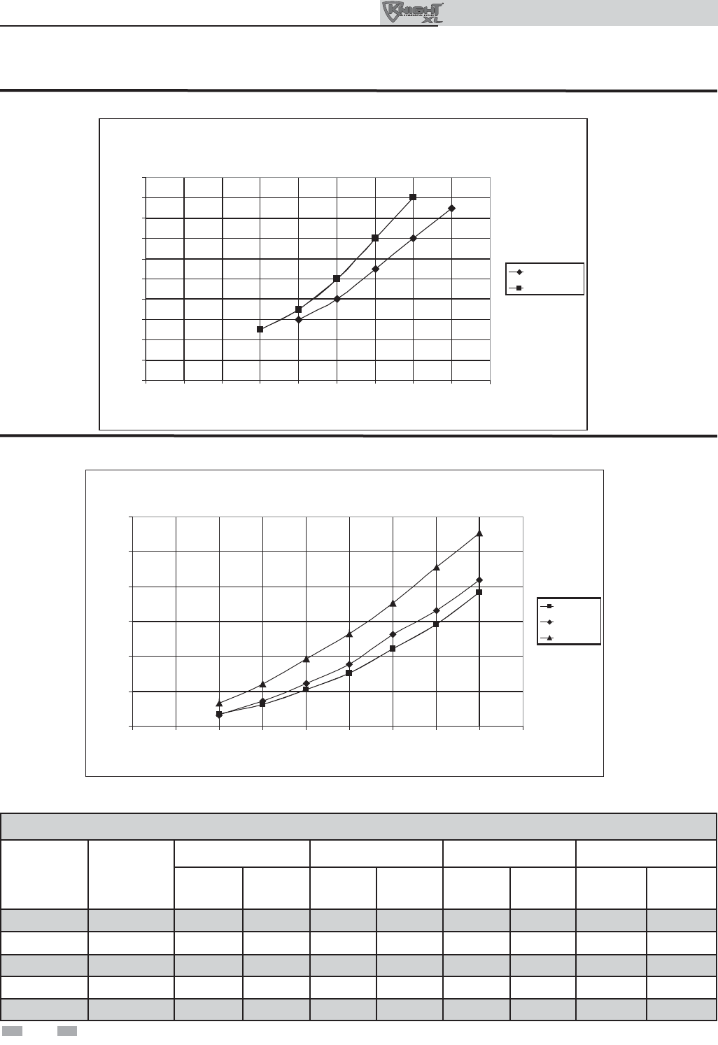
Circulator sizing
The Outdoor Knight XL heat exchanger does have a pressure
drop, which must be considered in your system design. Refer
to the graphs in FIG’s 3-5 and 3-6 for pressure drop through
the Outdoor Knight XL heat exchanger.
DRAIN
(TYPICAL)
AIR SEPARATOR
AIR VENT VALVE
EXPANSION TANK
LOW LOSS HEADER
(TYPICAL)
Y-STRAINER
(RECOMMENDED)
DRAIN
VALVE
FAST FILL VALVE
INDIRECT
DOMESTIC
HOT WATER
TANK
SYSTEM SENSOR
SYSTEM PUMP
TO FLOOR
DRAIN
TO
FROM
FROM
SYSTEM
TO
SYSTEM
BOILER PUMP
IMG00391
Figure 3-4B Near Boiler Piping w/Low Loss Header
12. Boiler purge valve:
Field supplied. The boiler purge valve is used to
remove entrapped air from the heat exchanger during
start-up.
13. System temperature sensor:
Lochinvar supplies a system temperature sensor. The
sensor is to be installed in the heating loop downstream
from the boiler hot water piping and heating loop
junction. The sensor should be located far enough
downstream to sense system diluted water temperature.
14. Y-Strainer:
Field supplied. A Y-strainer or equivalent multipurpose
strainer is recommended at the inlet of the heat exchanger
to remove system particles from older hydronic systems
and protect newer systems.
Variable speed pump option
Variable speed pump setup
Before operation, ensure the following:
- Pump is set for an input signal of 0 - 10VDC
by the dip switches on the pump control
- Pump is set for external signal control
(if applicable)
- Pump is set for linear output (if applicable)
- If pump does not come equipped with a
0 - 10 VDC input option, an optional module
will be required from the vendor
SMART SYSTEM / Multi-temperature
loop control option
The Outdoor Knight XL boiler is capable of producing
up to three (3) set point temperatures to meet different
space heating demands. When using more than one
temperature demand it is necessary to protect the
lower temperature loop from overheating. To help
aid with this protection, Lochinvar offers the Multi-
Temperature Loop Control Board Kit (RLY30086).
Outdoor Knight XL Installation & Operation Manual
18
Outdoor Knight XL Installation & Operation Manual
Figure 3-5 Pressure Drop vs. Flow - Models 400 and 501
Table 3B Sizing Information for Temperature Rise Applications_20°F, 25°F, 30°F and 35°F
Figure 3-6 Pressure Drop vs. Flow - Models 601 thru 801
0
2
4
6
8
10
12
14
16
18
20
0 5 10 15 20 25 30 35 40 45
KBN501
KBN400
Pressure Drop vs Flow
(Includes Boiler Secondary Piping)
Flow Rate (GPM)
Pressure Drop (Feet of Head)
O
O
0
10
20
30
40
50
60
0 102030405060708090
KBN801
KBN701
KBN601
Pressure Drop vs Flow
(Includes Boiler Secondary Piping)
Flow Rate (GPM)
Pressure Drop (Feet of Head)
O
O
O
TEMPERATURE RISE APPLICATIONS
Model MINIMUM
PIPE
SIZE
20°F 25°F 30°F 35°F
GPM FT/HD GPM FT/HD GPM FT/HD GPM FT/HD
400 1 1/2" 37 21 30 14 26 11 21 8
501 1 1/2" 46 23 37 16 32 13 26 10
601 2" 55 31 44 22 38 18 32 13
701 2" 65 30 52 20 45 16 37 11
801 2" 74 33 60 23 51 18 42 12
3 Hydronic piping
19
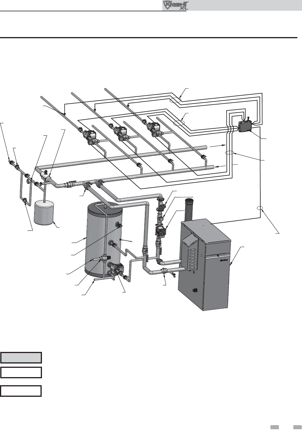
3 Hydronic piping (continued)
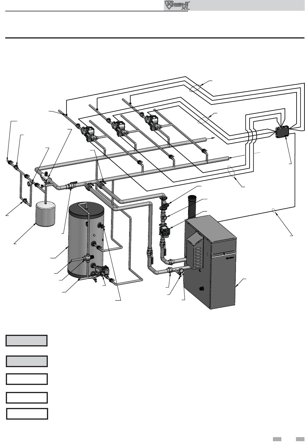
Figure 3-7 Single Boiler - Multiple Temperatures
Please note that these illustrations are meant to show system piping concept only, the installer is responsible
for all equipment and detailing required by local codes.
NOTICE
CAUTION Mixing valves are required for the protection of low temperature loops.
EXPANSION
TANK
AIR SEPARATOR
PRESSURE
REDUCING
VALVE
BALL VALVE
(TYPICAL)
UNION (TYPICAL)
PRESSURE
RELIEF
VALVE
FLOW CHECK VALVE
(TYPICAL)
INDIRECT DHW
TANK
PRESSURE
GAUGE
BOILER CIRCULATOR
COLD WATER IN
ANTI-SCALD
MIXING VALVE DOMESTIC
HOT WATER
CIRCULATOR
HOT WATER OUT
MAKE UP WATER
Y-STRAINER (RECOMMENDED)
TEMPERATURE
LOOP 1
TEMPERATURE
LOOP 2
TEMPERATURE
LOOP 3
BACK FLOW
PREVENTER
LOOP SENSOR (3X)
MULTI-TEMP
LOOP CONTROL
(OPTIONAL)
WIRES TO LOOP SENSORS
24V SIGNAL TO
MIXING VALVES
FROM
SYSTEM
120VAC
TO PUMPS
BOILER
SHIELDED CABLE
TO BOILER CONTROL
TO
SYSTEM
IMG00392
Outdoor Knight XL Installation & Operation Manual
Please note that these illustrations show an indoor tank to demonstrate piping concept only.
NOTICE
20
Outdoor Knight XL Installation & Operation Manual
3 Hydronic piping
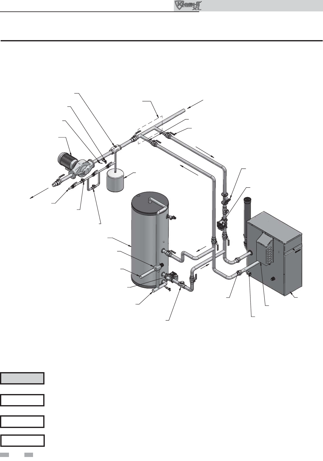
Figure 3-8 Single Boiler - Primary/Secondary Piping
NOTICE System fl ow should always remain higher than the required fl ow for the boiler(s) when the boiler(s) is in
operation to prevent short cycling and high limit issues.
Please note that these illustrations are meant to show system piping concept only, the installer is responsible
for all equipment and detailing required by local codes.
NOTICE
CAUTION Indirect water heaters are capable of transferring a limited number of Btu’s into the water. Ensure boiler
output does not not exceed indirect water heater transfer capabilities.
EXPANSION TANK
AIR SEPARATOR
PRESSURE REDUCING
VALVE
BACK FLOW
PREVENTER
BALL VALVE
(TYPICAL)
UNION (TYPICAL)
PRESSURE RELIEF
VALVE
FLOW CHECK
VALVE (TYPICAL)
INDIRECT DHW
TANK
BOILER
DRAIN
DRAIN POINT
(TYPICAL)
BOILER CIRCULATOR
COLD WATER IN
ANTI-SCALD
MIXING VALVE
SYSTEM SUPPLY SENSOR
(WHEN USED)
SYSTEM CIRCULATOR
TOSYSTEM
FROMSYSTEM
DOMESTIC
HOT WATER
CIRCULATOR
HOT WATER OUT
MAKE UP WATER
NOT TO EXCEED 4 PIPE DIA OR MAX. OF 12" APART
Y-STRAINER
(RECOMMENDED)
MAY SUBSTITUTE
LOW LOSS HEADER
IMG00393
Please note that these illustrations show an indoor tank to demonstrate piping concept only.
NOTICE
21
3 Hydronic piping (continued)
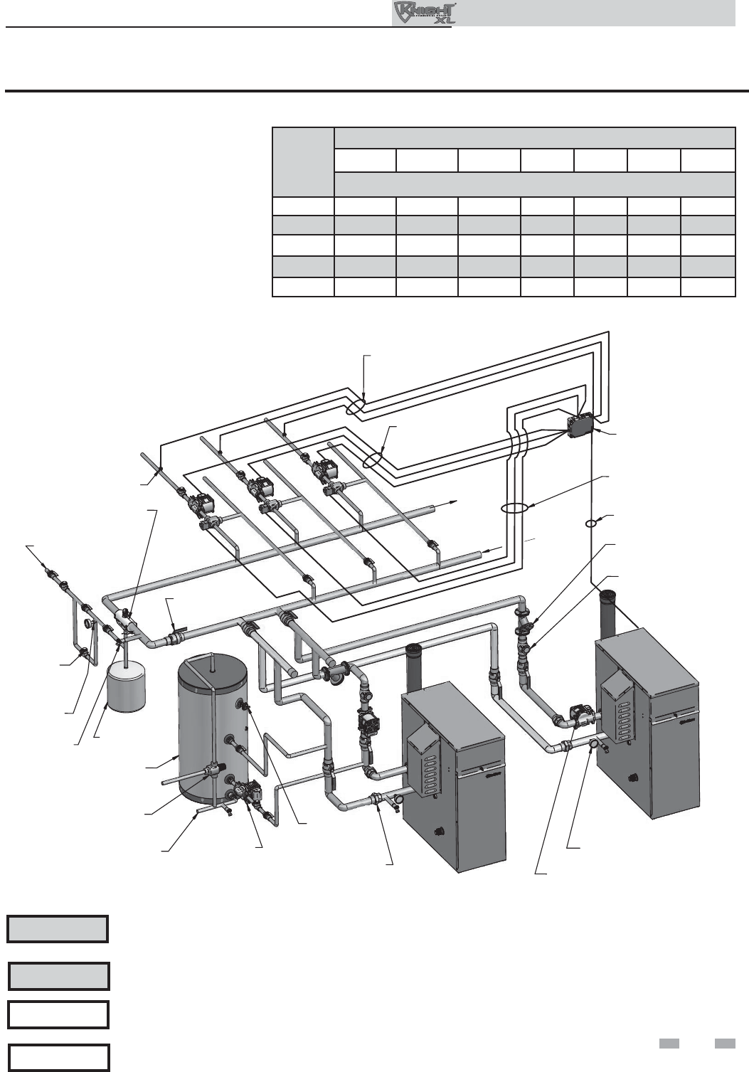
Figure 3-9 Multiple Boilers - Multiple Temperatures
Please note that these illustrations are meant to show system piping concept only, the installer is responsible
for all equipment and detailing required by local codes.
NOTICE
CAUTION Mixing valves are required for the protection of low temperature loops.
CAUTION
Model
Number of Units
2 3 4 5678
Manifold Pipe Sizes in Inches (mm)
400 2 1/2 (64) 3 (76) 3 1/2 (89) 4 (102) 4 (102) 5 (127) 6 (152)
501 3 (76) 3 1/2 (89) 4 (102) 5 (127) 5 (127) 6 (152) 6 (152)
601 3 1/2 (89) 4 (102) 5 (127) 5 (127) 6 (152) 6 (152) 8 (203)
701 3 1/2 (89) 5 (127) 5 (127) 6 (152) 6 (152) 8 (203) 8 (203)
801 4 (102) 5 (127) 5 (127) 6 (152) 8 (203) 8 (203) 8 (203)
Indirect water heaters are capable of transferring a limited number of Btu’s into the water. Ensure boiler
output does not not exceed indirect water heater transfer capabilities.
EXPANSION
TANK
AIR SEPARATOR
BALL VALVE
(TYPICAL)
UNION (TYPICAL)
PRESSURE
RELIEF
VALVE
FLOW CHECK
VALVE (TYPICAL)
INDIRECT DHW
TANK
BOILER 1
PRESSURE
GAUGE
DRAIN POINT
(TYPICAL)
ANTI-SCALD
MIXING VALVE
DOMESTIC
HOT WATER
CIRCULATOR
MAKE UP WATER
Y-STRAINER
(RECOMMENDED)
TEMPERATURE
LOOP 1
TEMPERATURE
LOOP 2
TEMPERATURE
LOOP 3
BOILER 2
BOILER CIRCULATOR
TEMPERATURE/PRESSURE
GAUGE
COLD WATER IN
WIRES TO
LOOP SENSORS
120VAC
TO PUMPS
24V SIGNAL TO
MIXING VALVES
SHIELDED CABLE
TO BOILER CONTROL
MULTI-TEMP
LOOP CONTROL
(OPTIONAL)
LOOP SENSOR (3X)
BACK FLOW
PREVETER
TO
SYSTEM
FROM
SYSTEM
IMG00394
Outdoor Knight XL Installation & Operation Manual
Please note that these illustrations show an indoor tank to demonstrate piping concept only.
NOTICE
22
Outdoor Knight XL Installation & Operation Manual
3 Hydronic piping
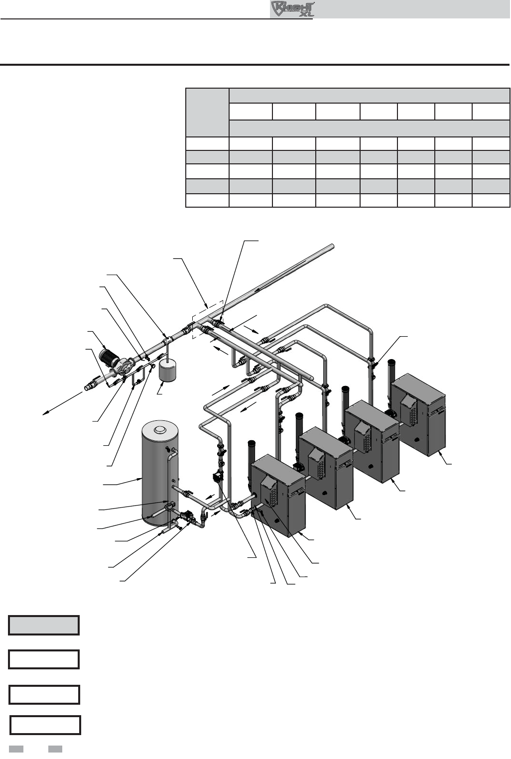
Figure 3-10 Multiple Boilers - Primary/Secondary Piping
Model
Number of Units
2345678
Manifold Pipe Sizes in Inches (mm)
400 2 1/2 (64) 3 (76) 3 1/2 (89) 4 (102) 4 (102) 5 (127) 6 (152)
501 3 (76) 3 1/2 (89) 4 (102) 5 (127) 5 (127) 6 (152) 6 (152)
601 3 1/2 (89) 4 (102) 5 (127) 5 (127) 6 (152) 6 (152) 8 (203)
701 3 1/2 (89) 5 (127) 5 (127) 6 (152) 6 (152) 8 (203) 8 (203)
801 4 (102) 5 (127) 5 (127) 6 (152) 8 (203) 8 (203) 8 (203)
EXPANSION
TANK
AIR SEPARATOR
PRESSURE REDUCING
VALVE
BACK FLOW
PREVENTER
BALL VALVE
(TYPICAL)
UNION (TYPICAL)
PRESSURE RELIEF
VALVE
FLOW CHECK
VALVE (TYPICAL)
INDIRECT DHW
TANK
BOILER 1
(LEADER)
TEMPERATURE /
PRESSURE GAUGE
PRESSURE GAUGE
DRAIN
DRAIN POINT
(TYPICAL)
BOILER CIRCULATOR
(TYPICAL)
ANTI-SCALD
MIXING VALVE
SYSTEM SUPPLY SENSOR
(WHEN USED)
SYSTEM CIRCULATOR
NOT TOEXCEED4PIPEDIAOR MAX.OF12"APART
BOILER 2
(MEMBER 1)
BOILER 3
(MEMBER 2)
BOILER 4
(MEMBER 3)
DOMESTIC
HOT WATER
CIRCULATOR
COLD WATER IN
HOT WATER OUT
MAKE UP WATER
Y-STRAINER
(TYPICAL)
(RECOMMENDED)
MAY SUBSTITUTE
LOW LOSS HEADER
FROMSYSTEM
TO SYSTEM
IMG00417
NOTICE System fl ow should always remain higher than the required fl ow for the boiler(s) when the boiler(s) is in
operation to prevent short cycling and high limit issues.
Please note that these illustrations are meant to show system piping concept only, the installer is responsible
for all equipment and detailing required by local codes.
NOTICE
CAUTION Indirect water heaters are capable of transferring a limited number of Btu’s into the water. Ensure boiler
output does not not exceed indirect water heater transfer capabilities.
Please note that these illustrations show an indoor tank to demonstrate piping concept only.
NOTICE
23
3 Hydronic piping (continued)
Figure 3-11 Single Boiler - Multiple Temperatures with DHW Piped as a Zone
EXPANSION
TANK
AIR SEPARATOR
BALL VALVE
(TYPICAL)
UNION (TYPICAL)
FLOW CHECK
VALVE (TYPICAL)
INDIRECT DHW
TANK
TEMPERATURE / PRESSURE
GAUGE
PRESSURE
GAUGE
DRAIN
DRAIN POINT
(TYPICAL)
BOILER CIRCULATOR
COLD WATER IN
ANTI-SCALD
MIXING VALVE DOMESTIC
HOT WATER
CIRCULATOR
HOT WATER OUT
MAKE UP WATER
Y-STRAINER
(RECOMMENDED)
TEMPERATURE
LOOP 1
TEMPERATURE
LOOP 2
TEMPERATURE
LOOP 3
PRESSURE RELIEF
VALVE
BACK FLOW
PREVENTER
FROM
SYSTEM
TO
SYSTEM
SHIELDED CABLE
TO BOILER CONTROL
LOOP SENSOR (3X)
MULTI-TEMP
LOOP CONTROL
(OPTIONAL)
WIRES TO
LOOP SENSORS
120VAC TO
PUMPS
24VAC SIGNAL
TO MIXING VALVES
PRESSURE
REDUCING
VALVE
BOILER
IMG00412
Please note that these illustrations are meant to show system piping concept only, the installer is responsible
for all equipment and detailing required by local codes.
NOTICE
Please note that the installer is responsible for ensuring DHW prioritization when piped as a zone.
NOTICE
CAUTION Mixing valves are required for the protection of low temperature loops.
CAUTION Indirect water heaters are capable of transferring a limited number of Btu’s into the water. Ensure boiler
output does not not exceed indirect water heater transfer capabilities.
Outdoor Knight XL Installation & Operation Manual
Please note that these illustrations show an indoor tank to demonstrate piping concept only.
NOTICE
24
Outdoor Knight XL Installation & Operation Manual
Connecting gas supply piping
1. Remove the top access panel and refer to FIG.’s 4-1 thru
4-3 to pipe gas to the boiler.
a. Install ground joint union for servicing, when
required.
b. Install a manual shutoff valve in the gas supply
piping outside boiler jacket when required by local
codes or utility requirements.
2. Install sediment trap / drip leg.
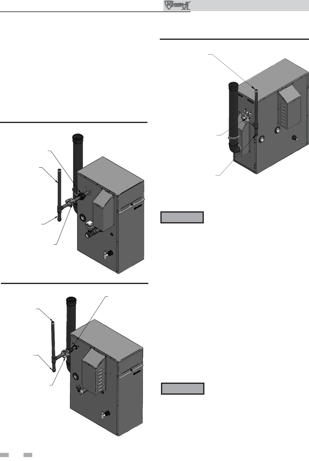
Figure 4-1 Gas Supply Piping - Model 400
3. Support piping with hangers, not by the boiler or its
accessories.
Do not check for gas leaks with an open
fl ame – use the bubble test. Failure to
use the bubble test or check for gas leaks
can cause severe personal injury, death, or
substantial property damage.
UNION
(FACTORY INSTALLED)
MANUAL
SHUTOFF VALVE
(FACTORY SUPPLIED)
GAS SUPPLY
SEDIMENT TRAP/
DRIP LEG
IMG00410
Figure 4-3 Gas Supply Piping - Models 601 - 801
4. Purge all air from the gas supply piping.
5. Before placing the boiler in operation, check the boiler
and its gas connection for leaks.
a. The appliance must be disconnected from the gas
supply piping system during any pressure testing of
that system at a test pressure in excess of 1/2 PSIG
(3.5 kPa).
b. The appliance must be isolated from the gas supply
piping system by closing a manual shutoff valve
during any pressure testing of the gas supply piping
system at test pressures equal to or less than 1/2 PSIG
(3.5 kPa).
c. The appliance and its gas connection must be leak
tested before placing it in operation.
The gas valve and blower will not support
the weight of the piping. Do not attempt
to support the weight of the piping with
the boiler or its accessories. Failure to
comply could result in severe personal
injury, death, or substantial property
damage.
WARNING
WARNING
6. Use pipe sealing compound compatible with propane
gases. Apply sparingly only to male threads of the pipe
joints so that pipe dope does not block gas fl ow.
IMG00411
UNION
GAS SUPPLY
SEDIMENT TRAP /
DRIP LEG
MANUAL
SHUTOFF
VALVE
(FIELD SUPPLIED)
Figure 4-2 Gas Supply Piping - Model 501
GAS SUPPLY
MANUAL SHUTOFF VALVE
(FACTORY SUPPLIED)
SEDIMENT TRAP
/ DRIP LEG
IMG00328
4 Gas connections
25
4 Gas connections (continued)
Failure to apply pipe sealing compound
as detailed in this manual can result
in severe personal injury, death, or
substantial property damage.
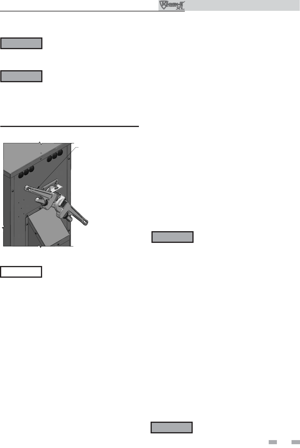
Use two wrenches when tightening gas
piping at boiler (FIG. 4-4), using one
wrench to prevent the boiler gas line
connection from turning. Failure to
support the boiler gas connection pipe
to prevent it from turning could damage
gas line components.
USE BACKUP WRENCH
TO PREVENT PIPE FROM
ROTATING
IMG00420
Figure 4-4 Inlet Pipe with Backup Wrench
Natural gas:
Pipe sizing for natural gas
1. Refer to Table 4A for pipe length and diameter. Based on
rated boiler input (divide by 1,000 to obtain cubic feet per
hour).
a. Table 4A is only for natural gas with specifi c gravity
0.60 inches, with a pressure drop through the gas
piping of 0.5 inches w.c.
b. For additional gas pipe sizing information, refer to
ANSI Z223.1 (or B149.1 for Canadian installations).
Natural gas supply pressure requirements
1. Pressure required at the gas valve inlet pressure port:
• Maximum 14 inches w.c. (3.5 kPa) with no fl ow
(lockup) or with boiler on.
• Minimum 4 inches w.c. (.99 kPa) with gas fl owing (verify
during boiler startup).
2. Install 100% lockup gas pressure regulator in supply line
if inlet pressure can exceed 14 inches w.c. (3.5 kPa) at any
time. Adjust lockup regulator for 14 inches w.c. (3.5 kPa)
maximum.
Propane Gas:
Pipe sizing for propane gas
1. Contact gas supplier to size pipes, tanks, and 100% lockup
gas pressure regulator.
Propane Supply Pressure Requirements
1. Adjust propane supply regulator provided by the gas
supplier for 14 inches w.c. (3.2 kPa) maximum pressure.
2. Pressure required at gas valve inlet pressure port:
• Maximum 14 inches w.c. (3.2 kPa) with no fl ow (lockup)
or with boiler on.
• Minimum 8 inches w.c. (1.9 kPa) with gas fl owing (verify
during boiler startup).
Maximum inlet gas pressure must not
exceed the value specifi ed. Minimum
value listed is for the purposes of input
adjustment.
WARNING
WARNING
NOTICE
WARNING Ensure that the high gas pressure regulator
is at least 10 feet (3 m) upstream of the
appliance.
WARNING Outdoor Knight XL boilers are typically
shipped ready to fi re on natural gas. Check
boiler rating plate to determine which fuel
the boiler is set for. If set to natural gas, it
may be converted to LP by installing an
orifi ce or by making a gas valve adjustment
(see page 12). In order to operate on LP
gas, an orifi ce MUST BE installed or a gas
valve adjustment MUST BE made. Failure
to comply could result in severe personal
injury, death, or substantial property
damage.
Outdoor Knight XL Installation & Operation Manual
26
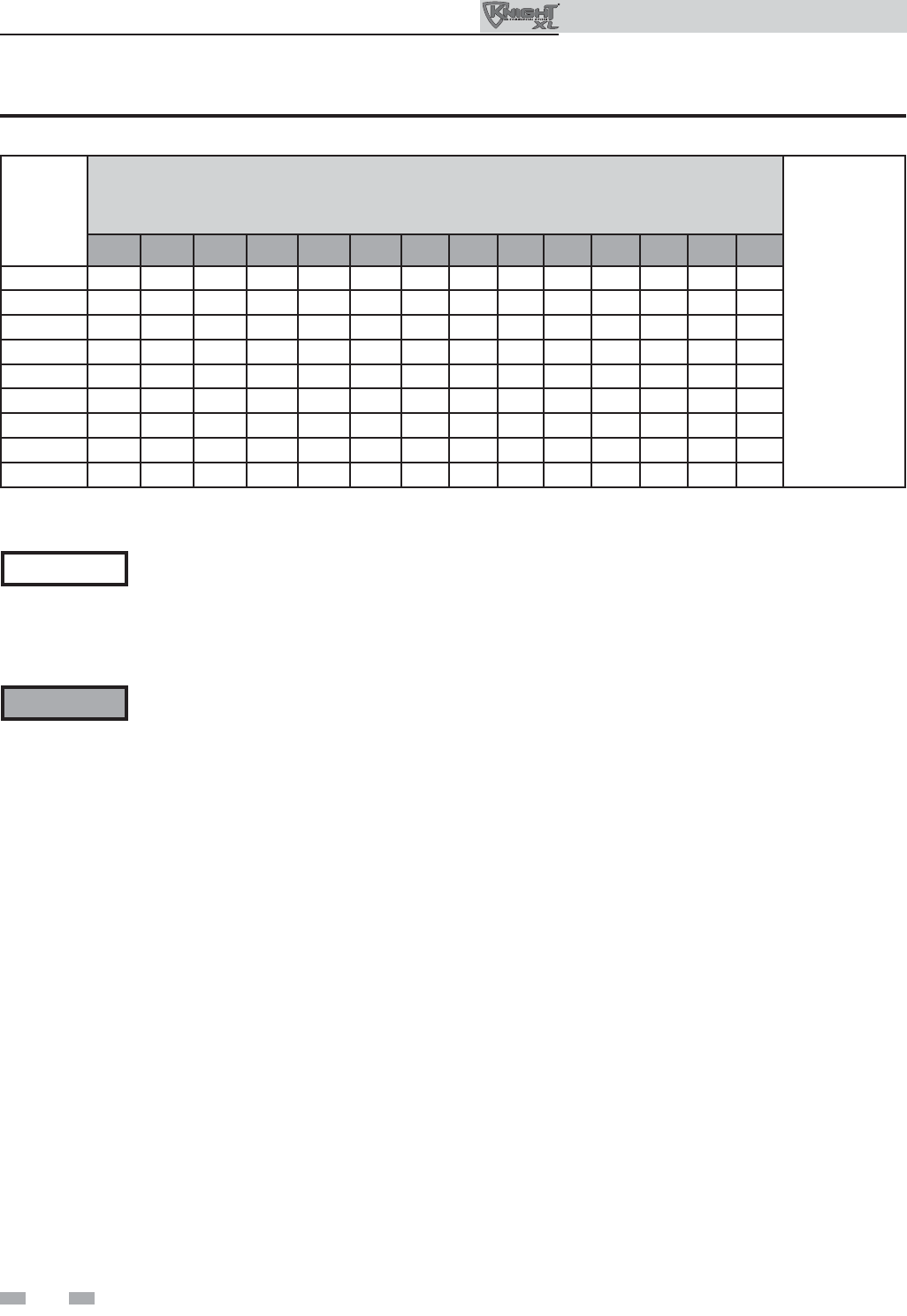
Outdoor Knight XL Installation & Operation Manual
Nominal
Iron Pipe
Size
(inches)
Natural Gas Pipe Capacity Chart
Length of Pipe in Straight Feet
Maximum
Capacity of Pipe
in Thousands of
Btu/hr per hour
for gas pressures
of 14 Inches
Water Column
(0.5 PSIG) or less
and a pressure
drop of 0.5 Inch
Water Column
(Based on NAT
GAS, 1025 Btu/
hr per Cubic Foot
of Gas and 0.60
Specifi c Gravity)
10 20 30 40 50 60 70 80 90 100 125 150 175 200
1/2 175 120 97 82 N/A N/A N/A N/A N/A N/A N/A N/A N/A N/A
3/4 369 256 205 174 155 141 128 121 113 106 95 86 79 74
1697 477 384 328 292 267 246 236 210 200 179 164 149 138
1-1/4 1400 974 789 677 595 543 502 472 441 410 369 333 308 287
1-1/2 2150 1500 1210 1020 923 830 769 707 666 636 564 513 472 441
24100 2820 2260 1950 1720 1560 1440 1330 1250 1180 1100 974 871 820
2-1/2 6460 4460 3610 3100 2720 2460 2310 2100 2000 1900 1700 1540 1400 1300
311200 7900 6400 5400 4870 4410 4000 3800 3540 3330 3000 2720 2500 2340
423500 16100 13100 11100 10000 9000 8300 7690 7380 6870 6150 5640 5130 4720
4 Gas connections
Table 4A Natural Gas Pipe Size Chart
The gas piping must be sized for the proper fl ow and length of
pipe, to avoid excessive pressure drop. Both the gas meter and
the gas regulator must be properly sized for the total gas load.
If you experience a pressure drop greater than 1 inch w.c.
(249 Pa), the meter, regulator, or gas line is undersized or in
need of service. Perform the steps below when checking inlet
gas supply:
1. Turn the main power switch to the “OFF” position.
2. Shut off gas supply at the manual gas valve in the gas
piping to the appliance.
3. On Models 400 - 501 loosen the set screw one (1) full turn
from inside the pressure tap on top of the gas valve. On
Models 601 - 801 remove the 1/8" (3 mm) pipe plug on the
inlet fl ange to the valve and install a suitable 1/8" (3 mm)
fi tting (fi eld supplied) for the manometer tubing. Place
the tubing of the manometer over the tap once the set
screw is loosened or the 1/8" (3 mm) fi tting is installed
(depending on model) as shown in FIG.’s 4-5 thru 4-7 on
page 27.
4. Slowly turn on the gas supply at the fi eld installed
manual gas valve.
5. Turn the power switch to the “ON” position.
6. Adjust the temperature set point on the control panel of
the SMART SYSTEM control module to call for heat.
7. Observe the gas supply pressure as the burner fi res at
100% of rated input. Percent of burner input will be
displayed on the control panel.
8. Ensure inlet pressure is within specifi ed range.
Minimum and maximum gas supply pressures are
specifi ed in this section of the manual.
9. If gas supply pressure is within normal range and no
adjustments are needed, proceed on to Step 11.
10. If the gas pressure is out of range, contact the gas utility,
gas supplier, qualifi ed installer or service agency to
determine the necessary steps to provide proper gas
pressure to the control.
11. Turn the power switch to the “OFF” position.
12. Shut off the gas supply at the manual gas valve in the gas
piping to the appliance.
13. Remove the manometer from the pressure tap on top of
the gas valve. On Models 400 - 501 re-tighten the set
screw inside the pressure tap. On Models 601 - 801
remove the 1/8" (3 mm) fi eld supplied fi tting and
reinstall the pipe plug removed in Step 3.
Check inlet gas supply
NOTICE CSA or UL listed fl exible gas connections
are acceptable, but you must exercise
caution to ensure that the line has adequate
capacity to allow your boiler to fi re at full
rate. Consult with local codes for proper
installation or service procedures.
DO NOT adjust gas valve outlet pressure.
Attempting to alter the gas valve outlet
pressure could result in damage to the valve,
causing potential severe personal injury,
death, or substantial property damage.
WARNING
27
WARNING When re-tightening the set screw, be sure
to tighten securely to prevent gas leaks.
Do not check for gas leaks with an open
fl ame -- use the bubble test. Failure to
use the bubble test or check for gas leaks
can cause severe personal injury, death, or
substantial property damage.
14. Turn on the gas supply at the manual gas valve.
15. Turn the power switch to the “ON” position.
16. Adjust the temperature set point on the control panel of
the SMART SYSTEM control module to the desired
water temperature so the appliance will call for heat.
17. Check burner performance by cycling the system while
you observe burner response. The burner should ignite
promptly. Flame pattern should be stable. Turn system
off and allow burner to cool, then cycle burner again to
ensure proper ignition and fl ame characteristics. Gas pressure
The gas pressure must remain between 4 inches w.c. (.99
kPa) minimum and 14 inches w.c. (3.5 kPa) maximum for
Natural gas and between 8 inches w.c. (1.9 kPa) minimum
and 14 inches w.c. (3.2 kPa) maximum for LP gas during
standby (static) mode and while in operating (dynamic)
mode. If an in-line regulator is used, it must be a minimum
of 10 feet (3 m) from the Outdoor Knight XL boiler. It is
very important that the gas line is properly purged by the gas
supplier or utility company. Failure to properly purge the
lines or improper line sizing, will result in ignition failure.
The problem is especially noticeable in NEW LP installations
and also in empty tank situations. This can also occur when
a utility company shuts off service to an area to provide
maintenance to their lines.
Gas valve replacement
The gas valve MUST NOT be replaced with a conventional
gas valve under any circumstances. As an additional safety
feature, this gas valve has a fl anged connection to the venturi
and blower.
Figure 4-5 Inlet Gas Supply Check - Model 400
DETAIL
IMG00414
LOOSEN THE SET SCREW ONE (1) FULL TURN
A
ND PLACE THE MANOMETER TUBING OVER
THE PRESSURE TAP
Figure 4-6 Inlet Gas Supply Check - Model 501
DETAIL
IMG00415
LOOSEN THE SET SCREW ONE (1) FULL TURN
A
ND PLACE THE MANOMETER TUBING OVER
THE PRESSURE TAP
Figure 4-7 Inlet Gas Supply Check - Models 601 - 801
DO NOT adjust gas valve outlet pressure.
Attempting to alter the gas valve outlet
pressure could result in damage to the
valve, causing potential severe personal
injury, death, or substantial property
damage.
Failure to follow all precautions could
result in fi re, explosion, or death!
WARNING
WARNING
DETAIL
REMOVE THE 1/8” (3 MM) PIPE PLUG ON
THE INLET FLANGE TO THE VALVE AND
INSTALL A SUITABLE 1/8” (3 MM) FITTING
(FIELD SUPPLIED) FOR THE MANOMETER
TUBING.
4 Gas connections (continued)
Outdoor Knight XL Installation & Operation Manual
28
Outdoor Knight XL Installation & Operation Manual
5 Field wiring
ELECTRICAL SHOCK HAZARD – For
your safety, turn off electrical power
supply before making any electrical
connections to avoid possible electric
shock hazard. Failure to do so can cause
severe personal injury or death.
Wiring must be N.E.C. Class 1.
If original wiring as supplied with boiler
must be replaced, use only type 105°C
wire or equivalent.
Boiler must be electrically grounded as
required by National Electrical Code
ANSI/NFPA 70 – latest edition.
Ensure that all wiring external to the
unit is enclosed in approved conduit.
Installation must comply with:
1. National Electrical Code and any other national, state,
provincial, or local codes, or regulations.
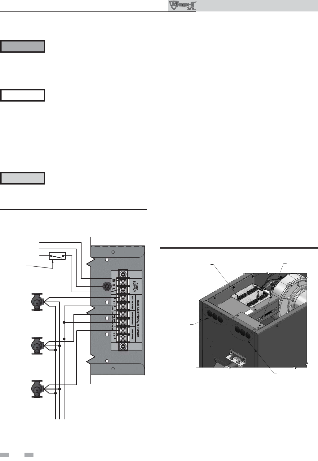
Line voltage connections
1. Connect 120 VAC power wiring to the line voltage terminal
strip in the junction box, as shown in FIG.5-1.
2. Provide and install a fused disconnect or service switch
(15 amp recommended) as required by the code (see
FIG. 5-1).
3. When connecting a domestic hot water (DHW) pump,
connect the wiring to the line voltage terminal strip as
shown in FIG. 5-1.
4. To activate a system pump, wire as shown in FIG. 5-1. Dry
contacts are sized for 1.5 hp/120V, 3 hp/240V or 30 amps.
DOMESTIC
HOT WATER
PUMP
BOILER
PUMP
SYSTEM
PUMP
120V SUPPLY
LINE
GROUND
NEUTRAL
W
G
BK
SERVICE
SWITCH
L2/N GL1
BK
G
W
BK
G
W
BK
G
W
Figure 5-1 Line Voltage Field Wiring Connections
Label all wires prior to disconnection
when servicing controls. Wiring errors
can cause improper and dangerous
operation.
WARNING
NOTICE
CAUTION
Low voltage connections
1. Route all low voltage wires through the knockouts in the
rear of the boiler, as shown in FIG. 5-2.
2. Connect low voltage wiring to the low voltage connection
board as shown in FIG. 5-3 on page 29 of this manual and
the boiler wiring diagram.
LINE VOLTAGE
JUNCTION BOX
LOW VOLTAGE
CONNECTION
BOARD
LOW VOLTAGE
WIRING
KNOCKOUT
PLUGS
LINE VOLTAGE
WIRING KNOCKOUT
PLUGS
IMG00329
Figure 5-2 Routing Field Wiring

29
5 Field wiring (continued)
Thermostat
1. Connect the room thermostats or end switches (isolated
contact only) to heat/loop demand 1, 2, or 3, as shown in
FIG. 5-3.
2. Install the thermostat on the inside wall away from
infl uences of drafts, hot or cold water pipes, lighting
fi xtures, television, sunlight, or fi replaces.
3. Thermostat anticipator (if applicable):
a. If connected directly to boiler, set for 0.1 amps.
b. If connected to relays or other devices, set to match
total electrical power requirements of connected
devices. See device manufacturers’ specifi cations
and thermostat instructions for details.
Outdoor temperature sensor
1. Mount the sensor on an exterior wall, shielded from
direct sunlight or fl ow of heat or cooling from other
sources.
2. Route sensor wires through a knockout at the rear of the
boiler (see FIG. 5-2).
3. Connect the outdoor temperature sensor (FIG. 5-3) to
the outdoor sensor terminals on the connection board
to enable outdoor reset operation of the Outdoor Knight
XL. If fi xed temperature operation is required, do not
install outdoor sensor.
DHW (Domestic Hot Water)
thermostat
Connect storage indirect water heater (DHW) thermostat
(FIG. 5-3) to the DHW thermostat terminals on the
connection board. If a tank sensor is connected (see DHW
Tank Sensor below) the tank thermostat is ignored.
DHW tank sensor
By installing a tank sensor, the SMART SYSTEM control can
perform the tank thermostat function. The SMART SYSTEM
control automatically detects the presence of this sensor, and
generates a DHW call for heat when the tank temperature
drops 6°F (3°C) below the tank set point, and fi nishes the call
for heat when the tank temperature reaches the tank set point.
The tank sensor included with the Lochinvar Squire® indirect
DHW tanks (TST20015) is the only sensor suitable for use
with the SMART SYSTEM control. Connect the sensor leads
to the Tank Sensor terminals on the low voltage connection
board (FIG. 5-3).
High gas pressure switch
1. If a switch is provided to detect excessive gas pressure,
remove the jumper wire from the terminals on the
connection board, and then connect them to its normally
closed contacts (FIG. 5-3).
Low gas pressure switch
1. If a switch is provided to detect low gas pressure, remove
the jumper wire from the terminals on the connection
board and connect them to its normally open contacts
(FIG. 5-3).
2. If both a high and low gas pressure switch is used, connect
their respective contacts in series, and connect them to the
terminals on the connection board (FIG. 5-3).
Failure to use the correct sensor may
result in the tank temperature being either
above or below the set point.
WARNING
If TST20015 is not compatible with the indirect tank, a
tank thermostat can be used to control the boiler. The
tank thermostat should be installed per the manufacturer’s
instructions and wired to the DHW Thermostat terminals on
the low voltage connection board (FIG. 5-3).
Variable speed system pump
If a variable speed pump is used in the primary loop, and
a 0-10V signal is available from the pump speed control,
this signal can be used by the SMART SYSTEM control to
anticipate changes in the building heat load. By connecting this
0 - 10V signal to the 0 - 10V SYS PUMP IN terminals, the boiler
(or cascade) can modulate up and down as the primary fl ow
increases and decreases.
Boiler pump speed output
This 0 - 10V output is available to control the speed of a variable
speed boiler pump. The SMART SYSTEM control will vary the
speed of this pump in order to maintain a minimum T across
the heat exchanger, as well as prevent high limit lockouts when
the fl ow in the primary loop is extremely low. Connect this
output to the 0 - 10V input on the boiler pump speed control.
Rate output
This output provides a 0 - 10V signal that is proportional to the
fi ring rate of the boiler. This may be used by a BMS system to
monitor the actual rate of the boiler.
Outdoor Knight XL Installation & Operation Manual

30
Outdoor Knight XL Installation & Operation Manual
5 Field wiring
ModBus
When the optional ModBus interface module is installed, the
RS-485 ModBus cable is connected to these terminals. Use
shielded, 2-wire twisted pair cable. If desired, the shield can
be connected to ground by installing a jumper wire between
terminals 1 and 3 on connector X5 on the optional ModBus
interface module.
Flow switch
1. A fl ow switch is used to guarantee fl ow through the boiler
before allowing it to fi re. The fl ow switch must be installed
at the boiler outlet.
2. Remove the jumper wire from the terminals on the
connection board and connect these terminals to the
normally open contacts on the fl ow switch (FIG. 5-3).
System supply sensor
1. By installing the system supply sensor into the supply of
the primary loop, the temperature of the system supply can
be controlled. The SMART SYSTEM control automatically
detects the presence of this sensor, and controls the boiler
fi ring rate to maintain the system supply temperature to the
set point (if the outlet sensor control is currently selected).
See the Outdoor Knight XL Service Manual for instructions
on how to use the inlet sensor as the controlling sensor.
When the inlet sensor is programmed as the controlling
sensor, it is vital that the SYSTEM SUPPLY sensor be
installed. DO NOT INSTALL THE SYSTEM SUPPLY
SENSOR INTO THE SYSTEM RETURN.
2. The TST2032 sensor provided with the boiler must be used
for the system sensor.
3. Connect these terminals to the system supply sensor
(FIG. 5-3).
Alarm contacts
The SMART SYSTEM control closes another set of contacts
whenever the boiler is locked out or the power is turned off.
This can be used to turn on an alarm, or signal a Building
Management System that the boiler is down.
Wiring of the cascade
When wiring the boilers for Cascade operation, select one
boiler as the Leader boiler. The remaining boilers will be
designated as Members. See page 36 “Confi guration of the
Cascade” for a detailed explanation of this procedure.
Connect the system supply sensor and outdoor air sensor (if
used) to the Leader boiler. For the Cascade system to work
properly the system supply sensor must be installed. The
location of the system supply sensor should be downstream
of the boiler connections in the main system loop (FIG.’s 3-7
through 3-11). The system supply sensor should be wired to
the Low Voltage Connection Board at the terminals marked
for the system sensor (see FIG. 5-3). The Leader control will
use the water temperature at the system supply sensor to
control the operation of the Cascade.
If outdoor air reset is desired, the outdoor air sensor should be
wired to the Low Voltage Connection Board at the terminals
marked for the outdoor air sensor (FIG. 5-3). If the outdoor
air sensor is connected, the Leader control will calculate the
water temperature set point based on the programmed reset
curve parameters. If the outdoor air sensor is not connected,
the Leader control will maintain the fi xed water temperature
set point that is programmed into the control.
If a Thermostat or Zone Control enable output is available,
it should be wired to the Low Voltage Connection Board
on the Leader boiler at the terminals marked for one of the
heat/loop demands 1-3 (FIG. 5-3). If the boilers are to run
continuously, connect a jumper wire between the R and W
terminals for the heat/loop demand input. This will initiate a
call for heat on the Cascade.
Communication between the Leader boiler and the Member
boilers is accomplished by using shielded, 2-wire twisted pair
communication cable. Connect one of the twisted pair wires
to Cascade terminal A on each of the Low Voltage Connection
boards, and the other wire of the twisted pair to Cascade
terminal B on each of the Low Voltage Connection Boards.
Connect the shield wires to one of the shield terminals on
the Low Voltage Connection Boards (FIG. 5-3). If more than
two boilers are on the Cascade, daisy chain the wiring from
the Cascade terminals on the second boiler to the Cascade
terminals on the third boiler, then from the third to the forth,
and so on. The connections between boilers can be made in
any order, regardless of the addresses of the boilers. Try to
keep each cable as short as possible.
Boiler management system
1. An external control may be connected to control either
the fi ring rate or the set point of the boiler. If the
external control uses a set of contacts to enable the boiler,
connect the contacts to the heat/loop demand 1 terminals.
Otherwise, the SMART SYSTEM control will be enabled by
the 0-10V signal.
2. Make sure the (-) terminal is connected to the (-) or
common output terminal of the external control, and
the (+) terminal is connected to the 0 - 10 VDC or (+)
terminal of the external control. Make sure that the (-)
voltage is not below ground.
Runtime contacts
The SMART SYSTEM control closes a set of dry contacts
whenever the burner is running. This is typically used by
Building Management Systems to verify that the boiler is
responding to a call for heat.

5 Field wiring (continued)
Figure 5-3 Low Voltage Field Wiring Connections
FLOW SWITCH
TANK THERMOSTAT
ROOM THERMOSTAT 3
SYSTEM SUPPLY SENSOR
BUILDING
MANAGEMENT
SYSTEM
COM
NO
LOW WATER
CUTOFF OUTDOOR SENSOR
TANK SENSOR
SHIELD SHIELD
TO
NEXT
BOILER
A
B
A
B
FROM
PREVIOUS
BOILER
ROOM THERMOSTAT 1
ROOM THERMOSTAT 2
AB
NOTE:
CONNECTION BOARD SPLIT FOR
ILLUSTRATION PURPOSES
WIRE AS
NEEDED
SYSTEM PUMP
SPEED
CONTROL
BOILER
PUMP
IMG00127
Outdoor Knight XL Installation & Operation Manual
31
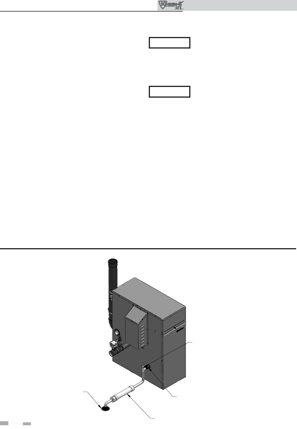
32
Outdoor Knight XL Installation & Operation Manual
6 Condensate disposal
Condensate drain
1. This boiler is a high effi ciency appliance that produces
condensate.
2. The side of the boiler has a 1/2 inch (12.7 mm) PVC
union for connection of a 1/2 inch (12.7 mm) PVC pipe
(FIG. 6-1).
3. Slope condensate tubing down and away from the boiler
into a drain or condensate neutralizing fi lter. Condensate
from the Outdoor Knight XL will be slightly acidic
(typically with a pH from 3 to 5). Install a neutralizing
fi lter if required by local codes.
A Neutralizer Kit (FIG. 6-1) is available from the factory
(KIT3087 for Models 400 - 501 and KIT3046 for Models
601 - 801).
4. Install the 1/2 inch (12.7 mm) PVC tee assembly (shipped
with the unit) as shown in FIG. 6-1.
5. Leave the top of the 1/2 inch (12.7 mm) tee OPEN. This
is needed as a vacuum break.
6. Do not expose condensate line to freezing temperatures.
Precautions should be taken to protect the condensate
management and disposal system during extended
periods of outdoor temperatures below 32°F.
7. Use only plastic tubing or piping as a condensate drain
line (FIG. 6-1).
Use materials approved by the authority
having jurisdiction. In the absence of other
authority, PVC and CPVC pipe must comply
with ASTM D1785 or D2845. Cement and
primer must comply with ASME D2564 or
F493.
8. A condensate removal pump is required if the boiler is
below the drain. When installing a condensate pump, select
one approved for use with condensing boilers and furnaces.
The pump should have an overfl ow switch to prevent
property damage from condensate spillage. The switch
should be wired in series with the blocked drain switch
inside the boiler (see FIG. 7-1 on page 34).
NOTICE
NOTICE To allow for proper drainage on large
horizontal runs, a second line vent may
be required and tubing size may need to
increase to 1 inch (25 mm).
The condensate line must remain
unbstructed, allowing free fl ow of condensate.
If condensate is allowed to freeze in the line
or if the line is obstructed in any other
manner, condensate can exit from the boiler
tee, resulting in potential water damage to
property.
1/2" PVC TEE ASSEMBLY
(FACTORY SUPPLIED)
NEUTRALIZER KIT
FLOOR DRAIN OR
DRAIN PAN 1/2" PVC UNION
(FACTORY SUPPLIED)
IMG00331
Figure 6-1 Condensate Disposal
KIT3087 shown for illustration purposes.
33
7 Start-up
Check/control water chemistry
Do not use petroleum-based cleaning or
sealing compounds in the boiler system.
Damage to elastomer seals and gaskets
in the system could occur, resulting in
substantial property damage.
Hardness less than 7 grains
1. Consult local water treatment companies for hard water
areas (above 7 grains hardness).
Chlorine concentration less than 200 ppm
1. Do not fi ll boiler or operate with water containing
chlorine in excess of 200 ppm.
2. Filling with chlorinated fresh water should be acceptable
since drinking water chlorine levels are much lower.
3. Do not use the boiler to directly heat swimming pool or
spa water.
Test/replace freeze protection fl uid
1. For systems using freeze protection fl uids, follow fl uid
manufacturer’s instructions.
2. Freeze protection fl uid must be replaced periodically due
to degradation of inhibitors over time. Follow all fl uid
manufacturer’s instructions.
Freeze protection (when used)
1. Determine freeze protection fl uid quantity using
system water content, following fl uid manufacturer’s
instructions. Boiler water content is listed on page 7.
Remember to include expansion tank water content.
2. Local codes may require a backfl ow preventer or actual
disconnect from city water supply.
3. When using freeze protection fl uid with automatic fi ll,
install a water meter to monitor water makeup. Freeze
protection fl uid may leak before the water begins to
leak, causing concentration to drop, reducing the freeze
protection level.
4. The freeze protection set points may be lowered when
freeze protection fl uid is used (see the Outdoor Knight
XL Service Manual).
Fill and test water system
1. Fill system only after ensuring the water meets the
requirements of this manual.
2. Close manual and automatic air vents and boiler drain
valve.
Eliminate all system leaks. Continual
fresh makeup water will reduce boiler life.
Minerals can build up in the heat exchanger,
reducing heat transfer, overheating the heat
exchanger, and causing heat exchanger
failure.
Purge air from water system
1. Purge air from system:
a. Connect a hose to the purge valve (see purge/drain
valves, in piping diagrams on page 22). Route the
hose to an area where water can drain and be seen.
b. Close the boiler or system isolation valve between
the purge valve and fi ll connection to the system.
c. Close zone isolation valves.
d. Open quick-fi ll valve on cold water makeup line.
e. Open purge valve.
f. One zone at a time, open the isolation valves. Allow
water to run through the zone, pushing out the air.
Run until no noticeable air fl ow is present. Close the
zone isolation valves and proceed with the next zone.
Follow this procedure until all zones are purged.
g. Close the quick-fi ll water valve and purge valve and
remove the hose. Open all isolation valves. Watch
that system pressure rises to correct cold-fi ll
pressure.
h. After the system has operated for a while, eliminate
any residual air by using the manual air vents located
throughout the system.
i. If purge valves are not installed in the system, open
the manual air vents in the system one at a time,
beginning with the lowest fl oor. Close the vent when
water squirts out. Repeat with remaining vents.
2. Open automatic air vent (diaphragm-type or bladder-
type expansion tank systems only) one turn.
3. Open other vents:
a. Starting on the lowest fl oor, open air vents one at a
time until water squirts out.
b. Repeat with remaining vents.
4. Refi ll to correct pressure.
3. Fill to correct system pressure. Correct pressure will vary
with each application.
a. The minimum cold water fi ll pressure for a
commercial system is 12 psi (82.7 kPa).
b. Pressure will rise when boiler is turned on and
system water temperature increases.
4. At initial fi ll and during boiler startup and testing, check
system thoroughly for any leaks. Repair all leaks before
proceeding further.
WARNING
CAUTION
Outdoor Knight XL Installation & Operation Manual
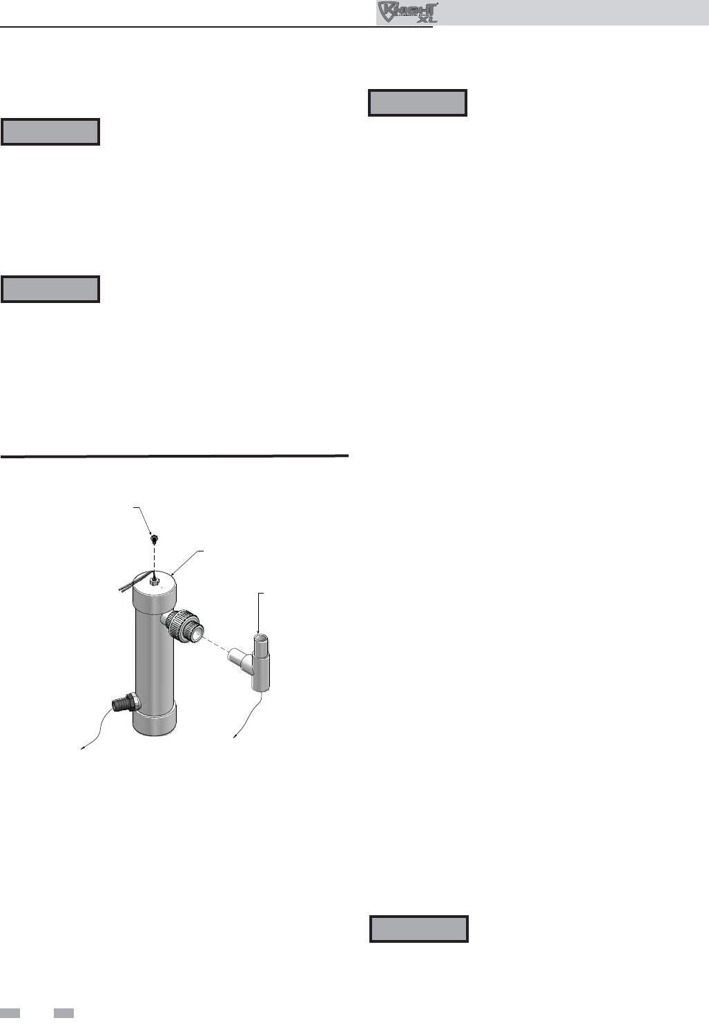
34
7 Start-up
Outdoor Knight XL Installation & Operation Manual
Check for gas leaks
Before starting the boiler, and during
initial operation, smell near the fl oor and
around the boiler for gas odorant or any
unusual odor. Remove the top access
panel and smell the interior of the boiler
enclosure. Do not proceed with startup
if there is any indication of a gas leak.
Use an approved leak detection solution.
Repair any leaks at once.
DO NOT adjust gas valve outlet pressure.
The gas valve is factory set for the correct
outlet pressure. This setting is suitable
for natural gas and propane, requiring
no fi eld adjustment. Attempting to
alter the gas valve outlet pressure could
result in damage to the valve, causing
potential severe personal injury, death, or
substantial property damage.
Propane boilers only – Your propane
supplier mixes an odorant with the propane
to make its presence detectable. In some
instances, the odorant can fade, and the
gas may no longer have an odor. Before
startup (and periodically thereafter), have
the propane supplier verify the correct
odorant level in the gas.
Check thermostat circuit(s)
1. Disconnect the two external wires connected to each
of the heat/loop demand terminals on the connection
board.
2. Connect a voltmeter across these two incoming wires.
Close each thermostat, zone valve, and relay in the
external circuit one at a time and check the voltmeter
reading across the incoming wires.
3. There should NEVER be a voltage reading.
4. If a voltage does occur under any condition, check and
correct the external wiring. (This is a common problem
when using 3-wire zone valves.)
5. Once the external thermostat circuit wiring is checked and
corrected if necessary, reconnect the external thermostat
circuit wires to the connection board. Allow the boiler to
cycle.
Inspect/fi ll condensate system
Inspect/check condensate lines and fi ttings
1. Inspect the condensate drain line, condensate PVC
fi ttings and condensate trap.
Fill condensate trap with water
1. Remove the PVC cap retaining screw from the PVC cap
(FIG. 7-1).
2. Remove the 2 inch PVC cap with the switch located at the
top of the trap (FIG. 7-1).
3. Fill with fresh water until the water begins to pour out of
the drain.
4. Replace the cap. Press the cap onto the trap until the cap
makes contact with the drain.
5. Replace the retaining screw.
The condensate trap (FIG. 7-1) must be
fi lled with water during all times of boiler
operation to avoid fl ue gas emission from
the condensate drain line. Failure to fi ll
the trap could result in severe personal
injury or death.
PVC TEE ASSEMBLY
(FACTORY SUPPLIED)
TO FLOOR
DRAIN
2” PVC CAP WITH
BLOCKED DRAIN SWITCH
RETAINING
SCREW
CONDENSATE FROM
HEAT EXCHANGER
Figure 7-1 Condensate Trap
WARNING
WARNING
WARNING
WARNING
35
7 Start-up (continued)
Final checks before starting the boiler
Read the Outdoor Knight XL Service Manual to
familiarize yourself with SMART SYSTEM control
module operation. Read this manual, page 33 for proper
steps to start boiler.
Verify the boiler and system are full of water and all
system components are correctly set for operation.
Verify the preparation procedures of Section 7, pages 33
and 34 have been completed.
Fill the vent condensate trap with water (removing the
retaining screw in order to remove the 2 inch PVC cap
with the switch located at the top of the trap). Replace
the cap. Press the cap onto the trap until the cap makes
contact with the drain. Replace the retaining screw.
Verify electrical connections are correct and securely
attached.
Start the boiler
1. Read and follow the Operating instructions in FIG. 7-2,
page 36.
If boiler does not start correctly
1. Check for loose connections, blown fuse or service switch
off?
2. Is boiler water temperature above 200°F (93°C)?
3. Is thermostat set below controlling sensor temperature?
4. Is gas turned on at meter or boiler?
5. Is incoming gas pressure less than 4 inches w.c. (.99 kPa)?
If none of the above corrects the problem, refer to the
Troubleshooting Section of the Outdoor Knight XL Service
Manual.
Check system and boiler
Check water piping
1. Check system piping for leaks. If found, shut down
the boiler and repair immediately. (See WARNINGS
on pages 33 and 34 (startup) regarding failure to repair
leaks.)
2. Vent any remaining air from the system using manual
vents. Air in the system will interfere with circulation and
cause heat distribution problems and noise.
Check gas piping
1. Check around the boiler for gas odor following the
procedure on page 46 of this manual (connecting gas
supply piping).
If you discover evidence of any gas leak,
shut down the boiler at once. Find the
leak source with a bubble test and repair
immediately. Do not start the boiler again
until corrected. Failure to comply could
result in severe personal injury, death, or
substantial property damage.
Propane boilers – verify conversion
1. Verify propane conversion has been completed per the
Propane Conversion instructions.
DO NOT adjust gas valve outlet pressure.
The gas valve is factory-set for the correct
outlet pressure. This setting is suitable
for natural gas and propane, requiring
no fi eld adjustment. Attempting to
alter the gas valve outlet pressure could
result in damage to the valve, causing
potential severe personal injury, death, or
substantial property damage.
Check fl ame and combustion
1. Turn the main power off to the boiler by placing the
“On/Off” switch in the OFF position.
2. Combustion measurements will be made from exhaust
opening.
3. Turn the main power on to the boiler by placing the
“On/Off” switch in the ON position.
WARNING
WARNING
WARNING Outdoor Knight XL boilers are typically
shipped ready to fi re on natural gas.
Check boiler rating plate to determine
which fuel the boiler is set for. If set to
natural gas, it may be converted to LP by
installing an orifi ce or by making a gas
valve adjustment (see page 12). In order
to operate on LP gas, an orifi ce MUST
BE installed or a gas valve adjustment
MUST BE made. Failure to comply could
result in severe personal injury, death, or
substantial property damage.
Outdoor Knight XL Installation & Operation Manual
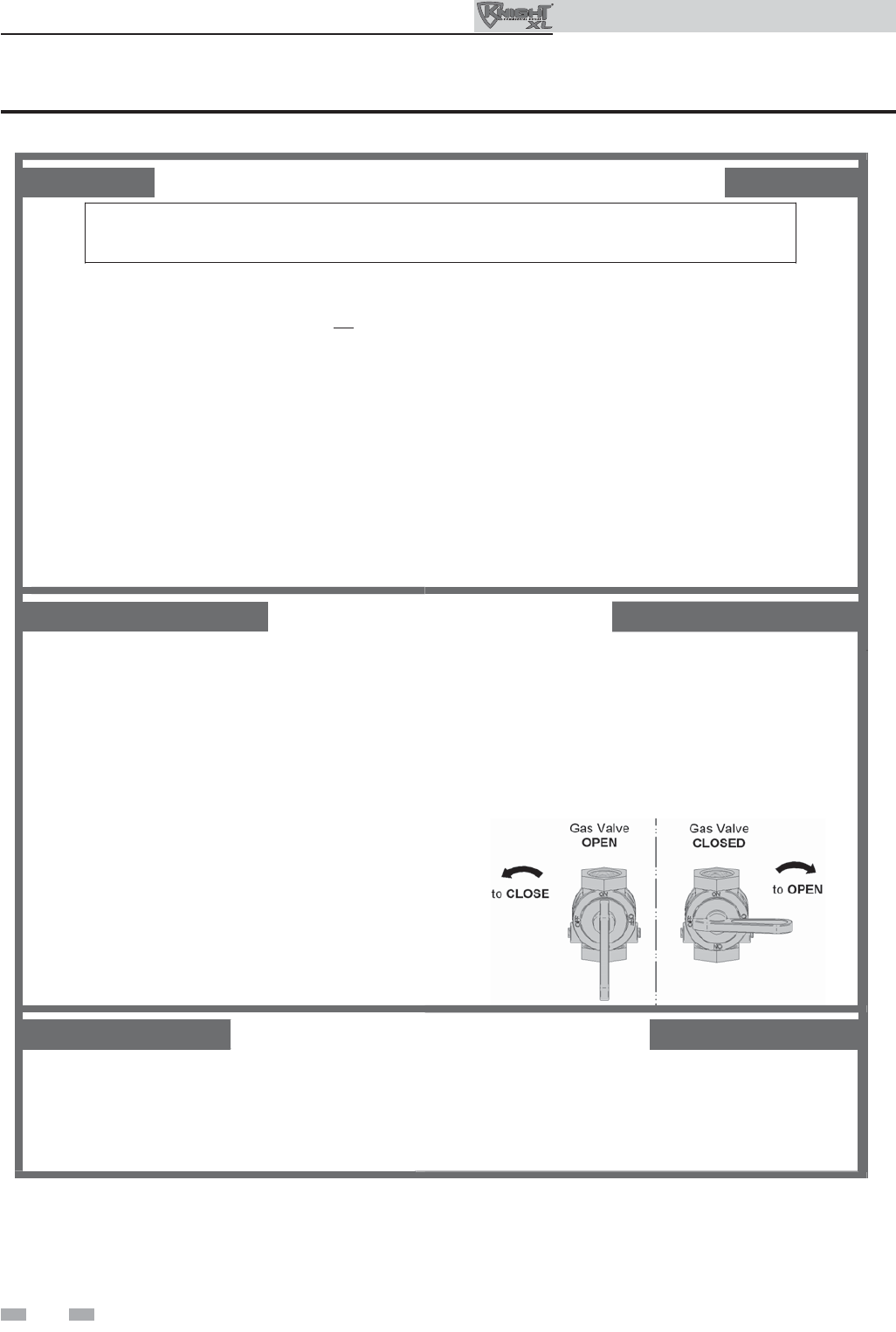
36
7 Start-up
Outdoor Knight XL Installation & Operation Manual
FOR YOUR SAFETY READ BEFORE OPERATING
WARNING: If you do not follow these instructions exactly, a fire or explosion
may result causing property damage, personal injury, or loss of life.
A. This appliance does not have a pilot. It is
equipped with an ignition device which
automatically lights the burner. Do not try
to light the burner by hand.
B. BEFORE OPERATING smell all around
the appliance area for gas. Be sure to
smell next to the floor because some gas
is heavier than air and will settle on the
floor.
WHAT TO DO IF YOU SMELL GAS
• Do not try to light any appliance.
• Do not touch any electric switch; do
not use any phone in your building.
• Immediately call your gas supplier from a
neighbor’s phone. Follow the gas supplier’s
instructions.
C. Use only your hand to turn the gas control knob.
Never use tools. If the handle will not turn by
hand, don’t try to repair it, call a qualified service
technician. Force or attempted repair may result
in a fire or explosion.
D. Do not use this appliance if any part has been
under water. Immediately call a qualified
service technician to inspect the appliance and
to replace any part of the control system and
any gas control which has been under water.
• If you cannot reach your gas supplier, call
the fire department.
1. STOP! Read the safety information
above on this label.
2. Set the thermostat to lowest setting.
3. Turn off all electric power to the
appliance.
4. This appliance is equipped with an
ignition device which automatically lights
the burner. Do not try to light the burner
by hand.
5. Remove top cover.
6. Turn gas shutoff valve counterclockwise
to “OFF”. Handle will be perpendicular to
pipe. Do not force.
7. Wait five (5) minutes to clear out any gas.
If you then smell gas, STOP! Follow “B”
in the safety information above on this label.
If you don’t smell gas, go to next step.
8. Turn gas shutoff valve clockwise to “ON”.
Handle will be parallel to pipe.
9. Install top cover.
10. Turn on all electric power to appliance.
11. Set thermostat to desired setting.
12. If the appliance will not operate, follow the
instructions “To Turn Off Gas To Appliance” and
call your service technician or gas supplier.
1. Set the thermostat to lowest setting.
2. Turn off all electric power to the appliance
if service is to be performed.
3. Remove top cover.
4. Turn gas shut off valve counterclockwise to
“OFF”. Handle will be perpendicular to pipe.
Do not force.
5. Install top cover.
LBL2284 REV -
TO TURN OFF GAS TO APPLIANCE
OPERATING INSTRUCTIONS
Figure 7-2 Operating Instructions
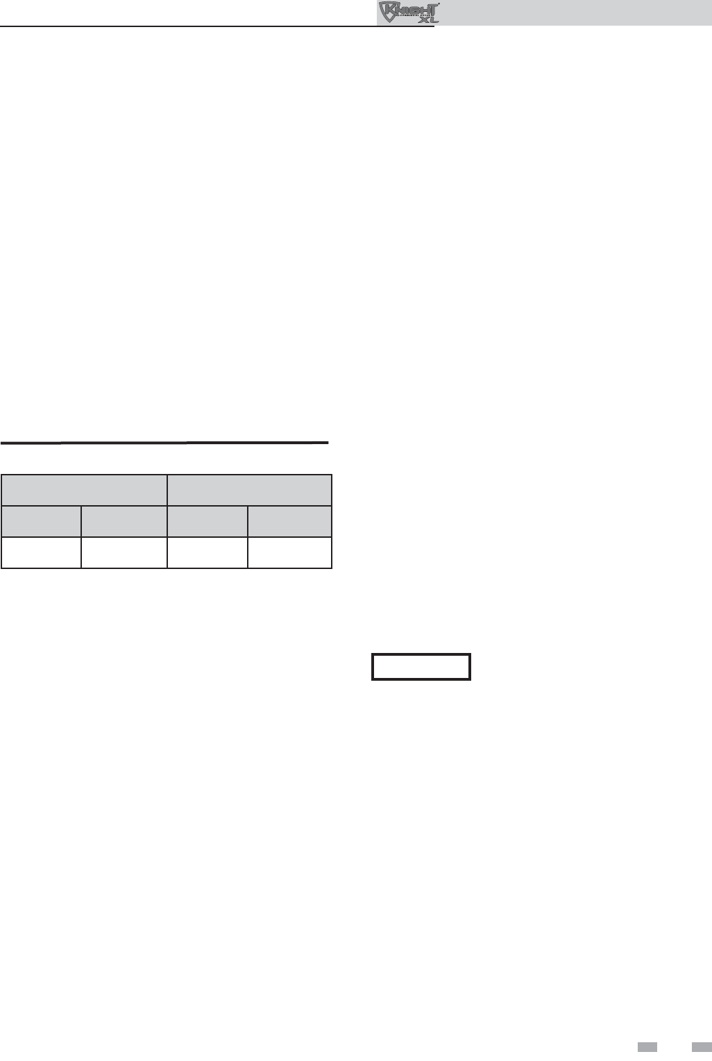
37
7 Start-up (continued)
Check fl ame and combustion (continued)
4. Place the boiler into the active position by pressing the
RIGHT SELECT [ON] key (FIG. 8-1, page 43).
5. Locate the pinhole button below the RESET button on
the display board (FIG. 8-1). Insert a thin wire (such as
a paper clip) into the hole and press the button once
and hold for 5 seconds to place the boiler into Service
Mode. In Service Mode the boiler will fi re at ignition
speed and will then modulate up to full fi re.
6. Once the boiler has modulated up to full fi re, measure
the combustion. The values should be in the range
listed in Table 7A below. The CO levels should be less
than 150 ppm for a properly installed unit.
If the combustion is not within the specifi ed range,
reference the Troubleshooting Section of the Outdoor
Knight XL Service Manual for possible causes and
corrective actions.
Set space heating operation
Determine controlling sensor
For space heating systems, the temperature control can be
based on one of three sensors; the inlet, outlet, or system
supply sensor. The SMART SYSTEM control is programmed
at the factory to control the temperature of the outlet
sensor. The control will automatically switch to the system
supply sensor once it is connected. If it is desired to base
the temperature control on the inlet sensor, the appropriate
parameter must be changed in the control. See the Outdoor
Knight XL Service Manual for a detailed explanation of this
procedure.
Verify space heat circulator mode
The Space Heating Mode controls both the system pump
(if connected), and the boiler pump. When the SMART
SYSTEM control receives a space heating call for heat, it turns
on the system pump. If the boiler is not heating an indirect
DHW (Domestic Hot Water) tank, and the set point is not
met, it also turns on the boiler pump. After the space heating
call for heat ends, the system pump continues to run for a
short period of time. The system pump can be programmed
to run continuously, except during outdoor shutdown. If
the boiler pump was running, it continues to run for a short
period of time as well. These pump delays are factory set to
30 seconds. If different delays are desired, the appropriate
parameters in the control must be changed. See the Outdoor
Knight XL Service Manual for a detailed explanation of this
procedure.
Adjust set point temperature(s)
Table 7A Flue Products Chart
7. Once the combustion analysis is complete, test the
safety shutoff device by turning the manual shutoff
valve to the OFF position and ensuring that the boiler
shuts down and registers an alarm. Turn the manual
shutoff switch to the ON position and reset the control.
8. Place the boiler back into normal operation.
Natural Gas Propane
CO2O2CO2O2
8.0% - 10% 3.0% - 6.5% 9.0% - 11% 4.1% - 6.9%
Please note that the brackets ([]) denote
screen status.
NOTICE
The NAVIGATION dial may be used during normal
operation to adjust the space heating and tank set point
temperatures.
1. From the Status Screen press the NAVIGATION dial.
2. Turn the NAVIGATION dial counterclockwise to select
the appropriate set point.
3. Press the NAVIGATION dial to adjust the temperature.
4. Once the desired temperature is displayed, press the
RIGHT SELECT [SAVE] key.
5. If necessary repeat Steps 3 and 4 to make adjustments to
additional set points.
6. Press the RIGHT SELECT [HOME[ key to upload the
changes.
7. If the RIGHT SELECT [SAVE] key is not pressed, the
new settings will be discarded.
Outdoor Knight XL Installation & Operation Manual
38
7 Start-up
Outdoor Knight XL Installation & Operation Manual
Set domestic hot water (DHW) operation
Verify DHW mode
There are two (2) modes of operation for DHW. In Normal
Mode, when a DHW demand begins, the control will start
the DHW pump, turn off the boiler pump (if running), and
modulate to bring the outlet temperature to the DHW boiler
set point. The maximum fi ring rate may be limited in this
mode if desired.
In Zone Mode it is assumed that the indirect DHW tank is
piped as a zone on the primary loop. When a DHW demand
begins, the control will turn on the DHW pump output, and
raise the system temperature set point to the DHW boiler set
point (if higher). The boiler pump will be turned on. The
system pump may be forced on, forced off, or not changed,
depending on the System Pump Mode selected (reference
the Outdoor Knight XL Service Manual for details). In this
mode, any low temperature zones (such as radiant heating)
may need additional controls to limit the water temperature
sent to those zones.
Set DHW boiler target temperature
When in the DHW Mode, the control will modulate to
maintain the boiler outlet temperature or system supply
temperature to a set point. This set point is set at the factory
to 180°F. If a different set point is desired, the appropriate
parameter in the control must be changed. See the Outdoor
Knight XL Service Manual for a detailed explanation of this
procedure.
Set maximum DHW fan speed
If the rated input of the indirect tank is less than the maximum
output of the boiler, change the maximum DHW fan speed
setting to limit the boiler output accordingly, see the Outdoor
Knight XL Service Manual for a detailed explanation of this
procedure.
NOTICE The internal clock does not adjust for
Daylight Savings Time and therefore, will
require a manual adjustment.
Confi guration of the cascade
7. Turn the NAVIGATION dial to adjust the minutes. Press
the NAVIGATION dial.
8. Turn the NAVIGATION dial to adjust the month. Press
the NAVIGATION dial.
9. Turn the NAVIGATION dial to adjust the date. Press the
NAVIGATION dial.
10. Turn the NAVIGATION dial to adjust the year. Press the
RIGHT SELECT [SAVE] key.
11. Press the RIGHT SELECT [HOME] key.
Please note that the brackets ([]) denote
screen status.
NOTICE
Set clock
When installed in a Cascade system, the individual controls must
be programmed for cascade operation. This is accomplished by
accessing the control parameters.
Press the [MENU] key for at least fi ve (5) seconds. Input the
Installer code as described in the Outdoor Knight XL Service
Manual. Once the control parameters have been accessed,
use the NAVIGATION DIAL to select the Control Mode
parameters. Press the NAVIGATION DIAL to access these
parameters.
Rotate the NAVIGATION dial to select the parameter “Cascade
Address”. Press the NAVIGATION dial to access this parameter.
Each appliance in the Cascade system must be programmed
with its own address. The boiler designated as the Leader will
have an address of 0. The remaining boilers in the Cascade
will be Members and have addresses from 1 - 7. Rotate the
NAVIGATION dial to select the appropriate address. Press the
RIGHT SELECT [SAVE] key.
Press the RIGHT SELECT [HOME] key to upload the address
into the control. Repeat this procedure for all boilers in the
Cascade, designating the Leader control and the Member
controls.
Please note that the brackets ([]) denote
screen status.
NOTICE
The SMART SYSTEM control has a built-in clock that it
uses for its night setback feature and for logging events. This
clock must be set when the boiler is installed, and anytime the
boiler has been powered off for more than 4 hours. Use the
following procedure to set the clock:
1. Press and hold the LEFT SELECT [MENU] key for at
least 5 seconds.
2. The display changes to read [PASSWORD],
with four (4) zeros below it.
3. Press the RIGHT SELECT [SAVE] key.
4. The display will then show a menu with the time and
date and temperature unit.
5. Press the NAVIGATION dial twice.
6. Turn the NAVIGATION dial to adjust the hours. Press
the NAVIGATION dial.
The clock is automatically updated whenever a PC is connected
and the Win_Pro-Installer program is started.

39
8 Operating information
General
How the boiler operates
The Outdoor Knight XL uses an advanced stainless steel heat
exchanger and electronic control module that allows fully
condensing operation. The blower pulls in air and pushes fl ue
products out of the boiler through the heat exchanger and
fl ue piping. The control module regulates blower speed to
control the boiler fi ring rate. The gas valve senses the amount
of air fl owing into the boiler and allows only the right amount
of gas to fl ow.
How the control module operates
The SMART SYSTEM control module receives inputs from
boiler sensors and external devices. The control module
activates and controls the blower and gas valve to regulate
heat input and switches the boiler, Domestic Hot Water
(DHW), and system pumps on and off as needed. The user
programs the module to meet system needs by adjusting
control parameters. These parameters set operating
temperatures and boiler operating modes. Boiler operation
can be based on boiler outlet water temperature, boiler inlet
water temperature, system temperature, a 0 - 10V signal, or
Modbus, depending on the parameter settings.
Control inputs and outputs
Room thermostat
There are three (3) heat/loop demand connections available
on this control. These inputs tell the boiler to provide water
for space heating. Each demand connection has its own set
point and outdoor air reset curve. When multiple demands
have a call for heat the control will give priority to the demand
with the highest set point.
Example: Assume that both heat/loop demand 1 and heat/
loop demand 2 have a call for heat. Demand 1 has a set point
of 110°F. Demand 2 has a set point of 140°F. The boiler will
regulate the system temperature to 140°F until Demand 2 has
been satisfi ed. Once Demand 2 has been satisifi ed the boiler
will provide 110°F water to the system.
SMART SYSTEM Multi-temp loop control
The Outdoor Knight XL boiler is capable of producing up
to three (3) set point temperatures to meet different space
heating demands. This device controls the temperatures
of up to three (3) separate loops, based on the settings for
the three (3) heat/loop demands (reference Lochinvar kit
RLY30086).
0 - 10V input (set point or power)
The Outdoor Knight XL can be controlled by a Building
Management System (BMS) using a 0 - 10 VDC signal. The
control can be confi gured by the installer to use this signal to
either control set point or fi ring rate.
The Outdoor Knight XL can also be programmed to accept a
call for heat from a 0 - 10V signal, reference the Outdoor Knight
XL Service Manual for a detailed explanation of this procedure.
DHW priority
The SMART SYSTEM control allows the connection of a DHW
thermostat or tank sensor to the low voltage connection board.
When a tank sensor is connected, the DHW thermostat input
is ignored. When a boiler is programmed for DHW Normal
Mode, the maximum fi ring rate can be limited to match the
input rating of the indirect tank coil.
DHW / space heating (SH) cycling
If a DHW call for heat is received while a space heating call is
in progress, and the DHW is in Normal Mode, the control will
start the DHW pump and shut the boiler pump off. The system
pump will remain on. For stand-alone boilers, if the space
heating call is still active while the DHW call is in operation, the
control will wait for 30 minutes (time adjustable by installer)
then it will switch back to the space heating demand. There is
a timer to switch from space heating to DHW and a timer to
switch from DHW to space heating. The control will switch
back and forth until one of the heat demands end. This function
does not apply to cascade systems.
Programmable controlling sensor
The control module is programmed to use the outlet sensor
as the control sensor by default. If a system supply sensor is
connected, the control automatically uses it as the control
sensor. For stand-alone boilers, the control sensor can be
changed by the installer to the inlet sensor. If the inlet sensor
is chosen as the controlling sensor, it is recommended that the
system supply sensor be installed in the system supply in order
to provide the best control of the inlet temperature.
Anti-cycling
After the burner turns off, the control will delay the next burner
cycle for a set time period (time is adjustable by the installer).
The time delay will be bypassed if the inlet water temperature
drops too far during the delay.
Boiler and system pump control
The boiler pump will run whenever the burner is fi ring, unless
the DHW is programmed for Normal Mode and the boiler is
heating the DHW tank. The boiler pump will run during Freeze
Protection Mode as well. It will continue to run for a short time
after the burner turns off or the Freeze Protection Mode ends.
The system pump will run whenever there is a space heating call
for heat, or the boiler goes into Freeze Protection Mode. It may
be programmed to run during a DHW call for heat when the
DHW is programmed for Zone Mode. It will continue to run
for a short time after the end of the heat demand or the Freeze
Protection Mode. The system pump can be programmed to run
continuously if desired, except during outdoor shutdown and/
or a DHW call for heat.
CAUTION When multiple temperature loops are
used, mixing valves are required for the
protection of any low temperature loops.
Outdoor Knight XL Installation & Operation Manual

40
8 Operating information
Outdoor Knight XL Installation & Operation Manual
Temperature control
Modulation
The Outdoor Knight XL is capable of modulating its fi ring
rate from a minimum of 20% to a maximum of 100%. The
fi ring rate is dictated by the call for heat (i.e., space heating
or domestic hot water), the heating load, ramp delay (if
enabled), and various other temperature limitations.
Ramp delay
For systems with lower fl ow, the SMART SYSTEM can
limit the fi ring rate (when enabled) when a space heating
call for heat starts, or when switching from a DHW call for
heat to a space heating call for heat. There are six (6) limits
that can be programmed, as well as six (6) time intervals
corresponding to each limit. The sixth limit will also limit
the fi ring rate for the rest of the call for heat.
Gradient limiting
If during operation of the boiler the outlet water temperature
is rising too quickly, the control will reduce the fi ring rate
to its lowest setting.
Outdoor air reset
If an outdoor air sensor is connected, the control module
will calculate the set points of the three (3) space heating
demands based on the programmed reset curves. The
installer can change the slope of the reset curves by several
adjustable parameters. The user can limit the maximum
set point for the system using the space heating set points.
Boost function
If outdoor air reset is active, and any space heating
demand has been active continuously for a set period of
time (time adjustable by installer) and there has been no
DHW demands, the control will increase the set point of
that demand by a fi xed number of degrees (adjustable by
installer). This process will continue until the space heating
demand ends, the set point reaches the programmed set
point or a maximum of 20 increases has occurred. Once the
system heat demand is satisfi ed, the set point will revert to
the value determined by the reset curve.
Night setback
The controller may be programmed to reduce the space
heating and DHW set points during certain times each week.
Seven different start and stop times may be programmed
for the space heating setback and seven start and stop times
for the DHW setback.
Flame current support
To prevent nuisance shutdowns when the boiler is fi ring
at minimum rates, the control will increase the fi ring rate
when the fl ame signal drops too low.
Protection features
Outlet temperature, fl ue temperature, and temperature
rise limiting
The outlet temperature is monitored by the boiler outlet
temperature sensor. When the outlet temperature exceeds
185°F, the unit will reduce the fan speed. If the outlet water
temperature exceeds 195°F (90°C) the control will shut the unit
down until it cools off.
The control module monitors the fl ue temperature by a sensor
located in the fl ue exhaust. If the fl ue temperature exceeds
215°F (102°C) the control will reduce the maximum fan speed.
If the fl ue temperature exceeds 240°F (115°C) the control will
shut the unit down. The unit will restart automatically once the
fl ue temperature drops 25°F (-4°C) and the minimum off time
has expired.
The control monitors the temperature difference between
the inlet and the outlet sensor. If this difference exceeds 55°F
(13°C) the control will reduce the maximum fan speed. If the
temperature difference exceeds 60°F (15°C) the control will
shut the unit down. The unit will restart automatically once the
temperature difference has dropped below 55°F (13°C) and the
minimum off time has expired.
Freeze protection
DO NOT install the boiler in a location where it is likely to
freeze.
The following integral feature of the SMART SYSTEM control
module provides some protection for the boiler only -- not for
the system.
• The SMART SYSTEM control module provides
freeze-up protection as follows when the boiler
water temperature drops below 45°F (7°C):
• Below 45°F (7°C), the boiler and system pumps
operate constantly.
• Below 37°F (3°C), the boiler turns on.
• Boiler and pumps turn off if boiler water
temperature rises above 45°F (7°C).
• Lower temperatures may be programmed for systems
with anti-freeze solutions.
This feature of the SMART SYSTEM
control module does not eliminate the
possibility of freezing. The installation must
still use recognized design, installation and
maintenance practice to prevent freeze
potential for the boiler and system.
CAUTION
NOTICE When system return temperatures
are maintained below the dew point,
condensation will form on the inside of the
boiler jacket causing some internal sheet
metal components to rust.

41
8 Operating information (continued)
Monitor external limits
Connections are provided on the connection board for
external limits such as fl ow switch, low water cutoff and
gas pressure switches. The SMART SYSTEM will shut off
the burner and inhibit relighting whenever any of these
external limits open.
Run-time and alarm outputs
The boiler provides dry contacts for indicating when the
boiler is running, and when it is unable to operate.
Run-time and cycle counting
The control uses two timers to monitor the total hours of
burner operation. One timer monitors the time the boiler
is in the Space Heating Mode. The other timer monitors
the time the boiler is fi ring in the DHW Mode.
The control uses two (2) ignition counters to monitor
the amount of boiler cycles. The fi rst counter counts all
ignitions of the control. The second counter counts only
ignition attempts that have failed.
Service reminder
The control can be programmed for service reminder
notifi cation. This notifi cation will become active when
either a set time frame has expired, or a set amount of
running hours or cycles has expired (all adjustable by the
installer). The display will show a Maintenance Required
screen. The installer’s name and phone number can be
programmed into the control. This information will appear
on the Maintenance Required screen. The service reminder
notifi cation can be reset or disabled by the installer.
The time dependent feature has been disabled by the
manufacturer. To enable this feature change the parameter
to the desired time interval, reference the Outdoor Knight
XL Service Manual for details regarding parameters.
Error logging
The control will hold in memory the last 10 lockouts as
well as the last 10 blockings. The date and time of the
occurrence will be recorded as well. Only the 10 most
current occurrences of each will be held in memory.
Boiler temperature regulation
Operating temperature (target)
The SMART SYSTEM control module senses water
temperature and regulates boiler fi ring and fi ring rate to
achieve a target temperature. The target temperature can
be set between 70°F (21°C) and 190°F (88°C).
• Target temperature is fi xed when the outdoor
sensor is not installed.
• Target temperature is calculated as described
on this page under “Outdoor Reset Operation”
and “Target Temperature Boost” when the
outdoor sensor is connected.
High limit operations
The Outdoor Knight XL is equipped with adjustable automatic
reset and manual reset high limits. The automatic reset high
limit has a maximum set point of 200°F and the manual reset
high limit has a maximum set point of 210°F.
When the outlet temperature exceeds 200°F, the automatic
high limit action occurs. The boiler shuts down until the outlet
water temperature cools below 190°F, and a 60 second timer
has expired. If the outlet temperature continues to increase, the
manual reset high limit action will occur at 210°F.
High limit test procedure
1. Turn ON the main power to the boiler by placing the
ON/OFF switch in the ON position.
2. From the Status Screen, press the NAVIGATION dial to
access the Set Points Screen.
3. Press the LEFT SELECT (LIMITS) key.
4. Select the manual reset high limit (MRHL) by rotating
the NAVIGATION dial counterclockwise, then press
the NAVIGATION dial.
5. Decrease the set point of the MRHL to below the current
outlet temperature (or to its minimum setting, whichever
is higher) by turning the NAVIGATION dial
counterclockwise.
6. Press the RIGHT SELECT [SAVE] key.
7. Press the RIGHT SELECT [HOME] key. The new
parameter will upload to the control.
8. If the current outlet temperature is above the new MRHL
set point, the MRHL will function causing boiler lockout.
If this occurs, skip to Step 11.
9. If the current outlet temperature is below the new MRHL
set point, locate the pinhole (SERVICE button) below the
RESET button on the display board. Insert a thin probe
(such as a paper clip) into the hole and press the button
continuously for fi ve (5) seconds to place the boiler into
Service Mode. In Service Mode, the boiler will fi re at
ignition speed and will then modulate up to full fi re.
10. Once the outlet temperature rises up to the MRHL set
point, the MRHL will function, causing the boiler to shut
down and lock out.
11. Repeat Steps 2, 3 and 4.
12. Set the MRHL to the appropriate set point by turning the
NAVIGATION dial clockwise.
13. Repeat Steps 6 and 7.
14. Press the RESET button to clear the lockout.
15. If needed, press the RIGHT SELECT [STOP] key to exit
Service Mode.
Please note that the brackets ([]) denote
screen status.
NOTICE
Outdoor Knight XL Installation & Operation Manual

42
8 Operating information
Outdoor Knight XL Installation & Operation Manual
Outdoor reset operation, if used
Target temperature with outdoor reset
This feature improves the system’s effi ciency as the outdoor
temperature warms up.
See the Outdoor Knight XL Service Manual to change the
settings.
Reset curve
The reset curves look at outdoor air temperature and adjusts
the set points.
Cascade
When multiple boilers are installed, they can be wired
together in a cascade sequence. A maximum of eight boilers
can be controlled from a single control. In this application
one boiler would be designated as the Leader control and all
others would be designated as Member controls. The Leader
control can be programmed to use Lead/Lag or Effi ciency
Optimization control methods.
Once the Leader boiler receives a call for heat from a room
thermostat, BMS, or Modbus, the control will determine what
the set point will be. If outdoor air reset is desired, connect
the outdoor air sensor to the terminals on the Low Voltage
Connection Board on the Leader boiler. The set point will be
calculated based on the programmed reset curve parameters.
See the Outdoor Knight XL Service Manual to program the
reset curve. If outdoor air reset is not desired, do not connect
the outdoor air sensor. A fi xed temperature set point can be
programmed into the control. See page 59 of this manual to
program the set point.
If the water temperature at the system supply sensor is less
than the set point + the turn-off offset - the off-on differential,
then the control will initiate a call for heat on the Cascade
(see the Outdoor Knight XL Service Manual for an explanation
of the offset and differential). The Leader will energize the
lead boiler on the Cascade. For a new startup this will be the
Leader boiler.
DHW, Night Setback, and Ramp Delay operation with
cascade
For normal mode DHW operation any boiler(s) in the Cascade
can be selected to provide heat for a DHW call. Select a boiler to
be designated as the DHW boiler. Connect the DHW thermostat
or sensor to the terminals on the Low Voltage Connection
Board marked for the corresponding device. When the boiler
receives a DHW call, the Leader control will take that boiler
out of the Cascade sequence. If another boiler is available, the
Leader will start it up to take its place.
The DHW boiler will adjust its set point to the programmed
DHW boiler set point and will adjust its fi ring rate to maintain
this. Once the DHW call has been satisfi ed, the Leader control
will place that boiler back into the Cascade sequence.
Switching of the boiler between DHW operation and SH
operation when there is a call for both does not occur in Cascade
Mode.
When DHW is programmed for Zone Mode, connect the DHW
thermostat or tank sensor to the Leader boiler. When a DHW
call is received, the Leader will modulate the entire Cascade to
bring the system supply temperature up to the DHW boiler set
point (if higher).
Night Setback operation of the boilers within the Cascade is
available. Programming of the Night Setback will be done
through the Leader boiler. Refer to the Outdoor Knight XL
Service manual for information regarding Night Setback.
Ramp Delay operation of the boilers as described in the Outdoor
Knight XL Service Manual is available when the boilers are part
of a Cascade system.
Sequence of the cascade
To equalize the run time of all boilers on the Cascade, the fi ring
sequence will automatically be changed at set intervals.
The sequence will be changed once every 24 hours. The
switching on/off sequence will be as follows:
TIME SWITCHING ON SEQUENCE
Start L-M1-M2-M3-M4-M5-M6-M7
1 hour M1-M2-M3-M4-M5-M6-M7-L
2 hours M2-M3-M4-M5-M6-M7-L-M1
If a boiler locks out or is used to heat an indirect DHW tank,
it will automatically be given the lowest priority for the rest of
that 24 hour period.
Low water cutoff protection
1. The SMART SYSTEM control module uses temperature
sensing of both supply and return areas of the heat
exchanger. If the fl ow rate is too low or the outlet
temperature too high, the control module modulates and
shuts the boiler down. This ensures boiler shutdown in
the event of low water or low fl ow conditions.
2. Some codes and jurisdiction may accept these integral
features of the control in lieu of requiring an additional
limit control or low water cutoff. Consult local jurisdiction
to determine. A low water cutoff is available from the
factory (WTR30024).

43
8 Operating information (continued)
Sequence of operation
OPERATION DISPLAY
1. Upon a call for heat, the gas pressure switch(es) must be closed.
2. Once the gas pressure switch(es) are closed, the control turns
on the appropriate pumps (system and boiler pumps for space
heating, DHW pump for DHW). The fl ow switch and/or LWCO
must close.
3. The air pressure switch and blocked drain switch must close.
4. The control starts the prepurge cycle by initiating the blower.
5. The control starts the trial for ignition by fi ring the spark
electrode and opening the gas valve.
6. If fl ame is not detected after the sparking ends, the control will
perform a postpurge, then start another prepurge cycle and try
to light the burner again. On the 501 and larger models, the control
will lock out if this second attempt also fails. On the 400 model,
the control will perform a total of 4 attempts before locking out.
7. If fl ame is detected, it holds the fi ring rate steady for a few
seconds to let the fl ame stabilize, then it begins to modulate the
fi ring rate based on a set point or some other command (such
as a 0-10V BMS signal).
Outdoor Knight XL Installation & Operation Manual
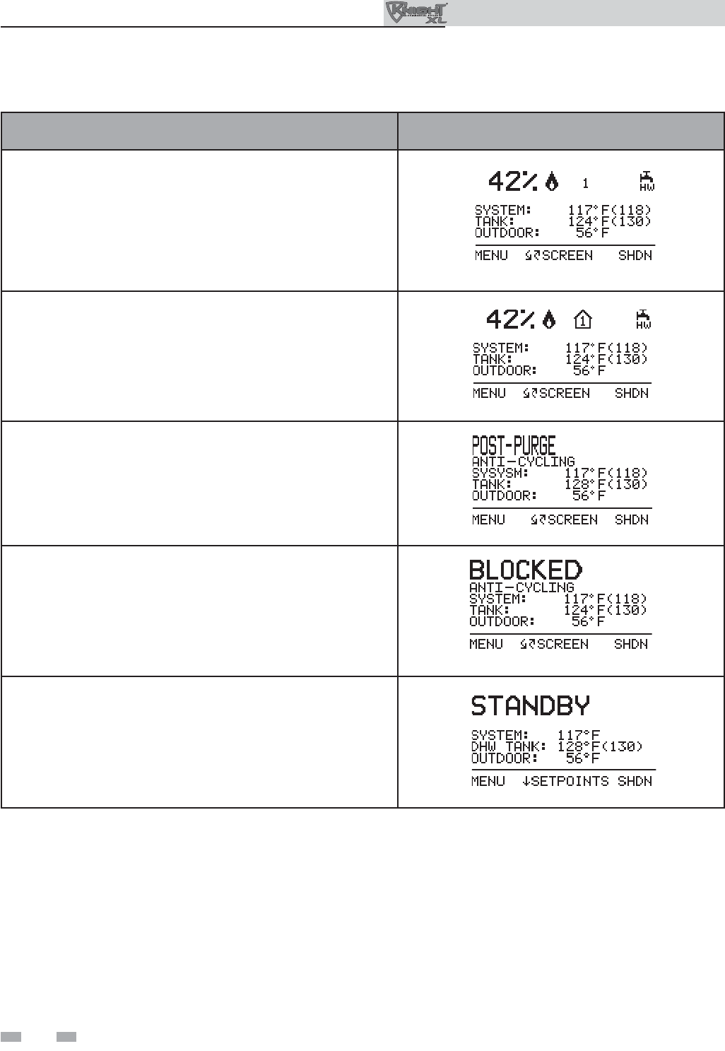
44
8 Operating information
Outdoor Knight XL Installation & Operation Manual
OPERATION DISPLAY
8. If the space heating call for heat is active, and the tank thermostat
or sensor starts a DHW call for heat, the boiler will switch to the
DHW mode. If programmed for normal DHW operation (not as a
zone), the DHW pump will turn on fi rst, then the boiler pump will
turn off (boiler and DHW pump operation briefl y overlap to ensure
fl ow is maintained through the unit). This will divert the boiler’s
outlet water from the heating system and send it to the tank coil
instead. The control will then modulate to maintain the outlet
temperature to the DHW boiler set point.
9. If the boiler is not part of a Cascade, and both the space heating
and DHW calls for heat remain active long enough, the boiler will
switch back and forth between the two heating modes until one of
them is satisfi ed.
10. Once both calls for heat are satisfi ed, the control will turn off
the burner.The blower will continue to run during the postpurge
period.
11. Any pumps that are running will continue to run for their respective
pump delay times before turning off, unless programmed to
remain on continuously. A 60 second anti-cycle period will start,
which will delay any new call for heat until it times out.
12. In Standby, ready to start a new cycle.
Sequence of operation (continued)

45
Access modes
User
The user can adjust space heating and tank target temperatures
by pressing the NAVIGATION dial when “SETPOINTS” is
fl ashing at the bottom of the display. The date and time, and
the temperature units can also be changed (see page 36).
Installer
Most parameters are available only to the installer, accessible
by entering the installer password, see the Outdoor Knight XL
Service Manual.
Saving parameters (reference the Parameter Table in
the Outdoor Knight XL Service Manual)
8 Operating information (continued)
Please note that the brackets ([]) denote
screen status.
NOTICE
To save parameters and exit programming:
Press the RIGHT SELECT [SAVE] key and then press the
RIGHT SELECT [HOME] key.
To enter a parameter and continue programming:
Press the RIGHT SELECT [SAVE] key 1 time to return to the
parameter listings; press again to return to the menu listings.
Remember to press the RIGHT SELECT [HOME] key when
fi nished programming in order to save the changes made.
See the Outdoor Knight XL Service Manual for a detailed
description of parameters and access modes.
Outdoor Knight XL control module
NAVIGATION DIAL
Figure 8-1 Control Panel
Use the control panel (FIG. 8-1) to set temperatures, operating conditions, and monitor boiler operation.
The information on the bottom of the display shows the functions of the two SELECT keys (on either corner), and the
NAVIGATION dial (in the center):
MENU = Left SELECT Key
SETPOINTS = NAVIGATION Dial - Pressing Down
SHDN = Right SELECT Key
Outdoor Knight XL Installation & Operation Manual
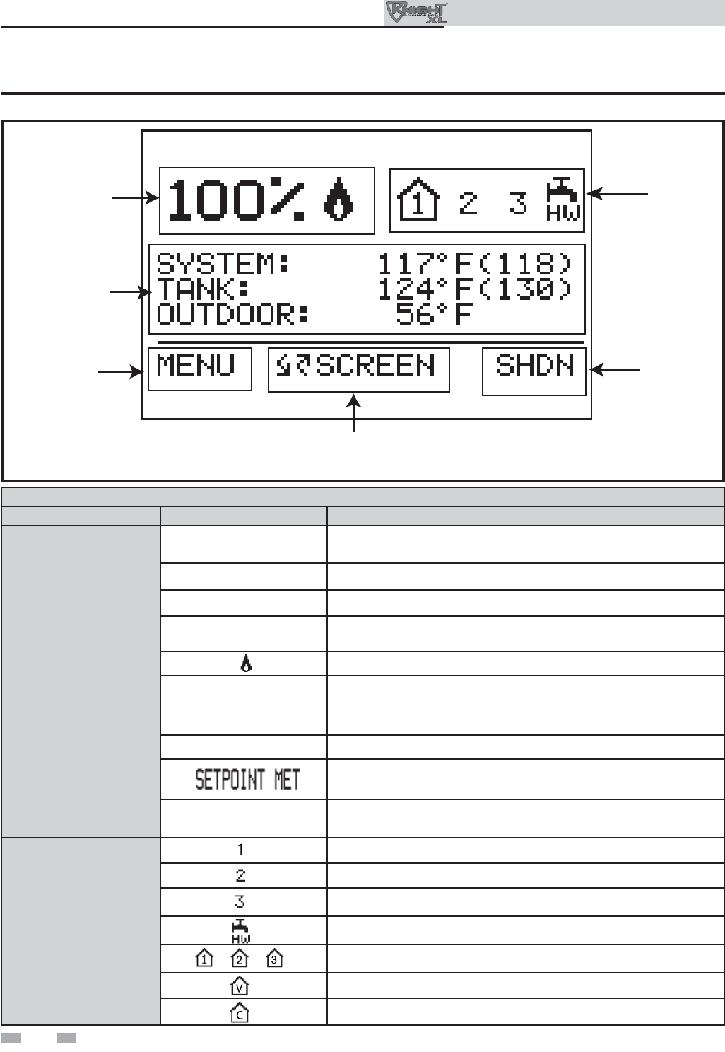
46
8 Operating information
Status Display Screens
Section Display Description
A
(Boiler Status
Bar)
STANDBY The unit has not received a call for heat from a remote thermostat nor
has it received a call for heat from a DHW thermostat.
START The unit has begun a burn cycle and is checking all safety circuits.
PREPURGE The unit has initiated a prepurge period on a call for heat.
IGNITION The unit has begun a spark period to ignite the main burner.
The unit has fi red and is running at the displayed percentage.
POSTPURGE
The call for heat has been satisfi ed and the unit runs the fan for an
additional postpurge period to clear the combustion chamber and
vent system of residual fl ue products.
SHUTDOWN The unit has been placed in the OFF position.
The controlled temperature has exceeded its set point and its offset.
BLOCKED The unit has detected a condition that has temporarily interrupted
the current call for heat.
B
(Call for Heat
Indicators)
Room Thermostat 1 has a call for heat.
Room Thermostat 2 has a call for heat.
Room Thermostat 3 has a call for heat.
The tank thermostat or sensor has a call for heat.
Indicates which room thermostat demand shows priority.
The unit is being controlled by a 0 - 10V BMS signal.
The member unit is supplying heat while in Cascade Mode.
A
C
D
B
F
E
(BOILER
STATUS)
(OPERATIONAL
INFORMATION)
(LEFT SELECT
KEY)
(RIGHT SELECT KEY)
(NAVIGATION DIAL)
(CALL FOR
HEAT)
Figure 8-2 Status Display Screen
%
Outdoor Knight XL Installation & Operation Manual
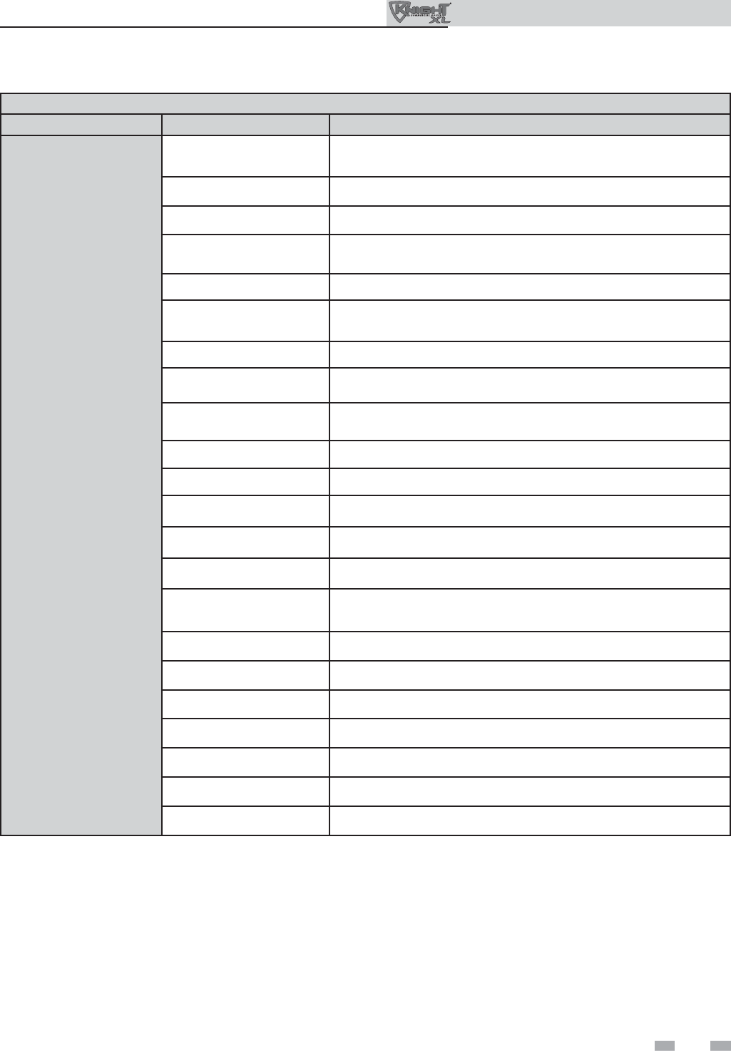
47
8 Operating information (continued)
Status Display Screens (cont’d)
Section Display Description
C
(Operational
Information)
SYSTEM: The temperature read by the system supply sensor (if connected).
TANK: The temperature read by the tank sensor (if connected).
OUTDOOR: The temperature read by the outdoor sensor (if connected).
INLET TEMP: The temperature read at the inlet to the heat exchanger.
OUTLET TEMP: The temperature read at the outlet of the heat exchanger.
DELTA T: The temperature difference between the inlet and the outlet of the
heat exchanger.
FLUE TEMP: The temperature read by the fl ue sensor.
FLAME CURRENT: The current measured by the fl ame sense circuit.
FAN SPEED: The speed of the combustion blower.
BOILER PUMP: The status of the boiler pump output.
SYSTEM PUMP: The status of the system pump output.
DHW PUMP: The status of the DHW pump output.
BMS VOLTAGE: The voltage received from a BMS system.
BLR PUMP OUTPUT: The speed signal sent to a variable speed boiler pump in percent.
SYS PUMP INPUT: The speed signal received from a variable speed system pump control.
RATE OUTPUT: A 0 - 10V signal indicating the fi ring rate of the boiler.
SH RUN HOURS: The total hours of operation in the Space Heating Mode.
SH CYCLES: The total burner cycles in the Space Heating Mode.
DHW RUN HOURS: The total hours of operation in the DHW Mode.
DHW CYCLES: The total burner cycles in the DHW Mode.
LAST 10 FAULTS NO:* The last 10 lockouts.
NIGHT SETBACK Shows the next Night Setback trigger (if active).
Outdoor Knight XL Installation & Operation Manual
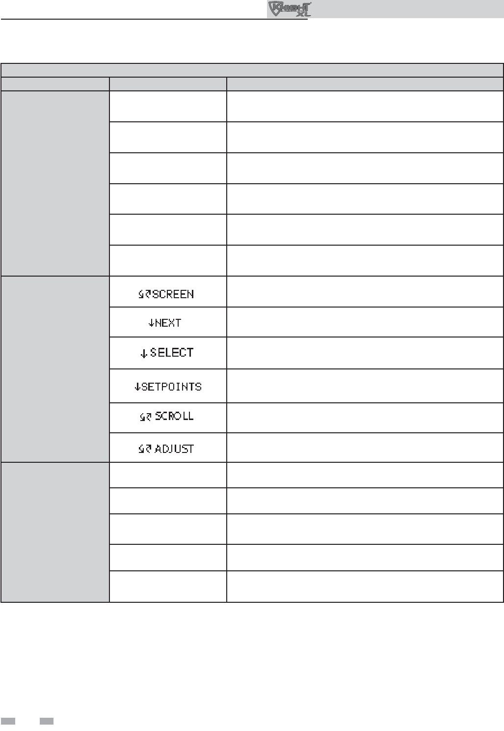
48
8 Operating information
Status Display Screens (cont’d)
Section Display Description
D
(LEFT SELECT
key function)
MENU Press and hold the LEFT SELECT key for 5 seconds to enter the Menu
Screen.
EXIT Press the LEFT SELECT key to exit the current screen or setting.
YES Press the LEFT SELECT key to confi rm that the boiler needs to
shutdown.
LIMITS Press the LEFT SELECT key to enter the screen that allows you to
adjust the limit settings.
HOME Press the LEFT SELECT key to return to the Status Screen and upload
parameter changes.
SKIP Press the LEFT SELECT key when in the Night Setback Screen to
access the Night Setback Skip Screen.
E
(NAVIGATION
Dial Function)
Turning the NAVIGATION dial will select the next or previous Status
Screen.
Pressing the NAVIGATION dial will show the next fault, NSB (Night
Setback) trigger, or ramp delay setting.
Pressing the NAVIGATION dial will select the setting indicated by
the cursor.
Pressing the NAVIGATION dial will display the Set Points Screen.
Turning the NAVIGATION dial will move the cursor up or down.
Turning the NAVIGATION dial will increase or decrease the current
setting.
F
(RIGHT SELECT
key function)
SHDN Press the RIGHT SELECT key to turn the boiler OFF.
ON Press the RIGHT SELECT key to turn the boiler ON.
NO Press the RIGHT SELECT key to cancel the shutdown operation.
SAVE Press the RIGHT SELECT key to save the current change.
HOME Press the RIGHT SELECT key to return to the Status Screen and
upload parameter changes.
Outdoor Knight XL Installation & Operation Manual
49
Maintenance and annual startup
Table 9A Service and Maintenance Schedules
Owner maintenance
(see the Outdoor Knight XL User’s Information
Manual for instructions)
Daily • Check boiler area
• Check pressure/temperature
gauge
Monthly
• Check air and vent termination
screens
• Check relief valve
• Check condensate drain system
Periodically
• Test low water cutoff (if used)
• Reset button (low water cutoff)
Every
6 months
• Check boiler piping (gas and
water) for leaks
• Operate relief valve
End
of season
months
• Shut boiler down (unless boiler
used for domestic hot water)
9 Maintenance
Service technician
(see the following pages for instructions)
General:
• Address reported problems
• Inspect interior; clean and vacuum if
necessary;
• Clean condensate trap and fi ll with fresh
water
• Check for leaks (water, gas, fl ue,
condensate)
• Verify fl ue and air passage ways in good
condition and sealed tight
• Check system water pressure/system
piping/expansion tank
• Check control settings
• Check ignition and flame sense
electrodes (sand off any deposits; clean
and reposition)
• Check wiring and connections
• Perform start-up checkout and performance
verifi cation per Section 7.
• Flame inspection (stable, uniform)
• Flame signal (at least 10 microamps at
high fi re)
• Clean the heat exchanger if fl ue temperature
is more than 54°F (30°C) above return water
temperature.
If combustion or performance
indicate need:
• Clean heat exchanger
• Remove and clean burner using
compressed air only
• Clean the blower wheel
ANNUAL START-UP
Outdoor Knight XL Installation & Operation Manual
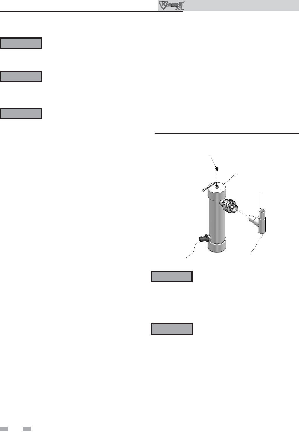
50
9 Maintenance
Follow the Service and maintenance procedures given throughout this manual and in component literature
shipped with the boiler. Failure to perform the service and maintenance could result in damage to the boiler
or system. Failure to follow the directions in this manual and component literature could result in severe
personal injury, death, or substantial property damage.
The boiler should be inspected annually only by a qualifi ed service technician. In addition, the maintenance
and care of the boiler designated in Table 9A and explained on the following pages must be performed to
assure maximum boiler effi ciency and reliability. Failure to service and maintain the boiler and system could
result in equipment failure.
Electrical shock hazard – Turn off power to the boiler before any service operation on the boiler except as
noted otherwise in this instruction manual. Failure to turn off electrical power could result in electrical shock,
causing severe personal injury or death.
Address reported problems
1. Inspect any problems reported by the owner and correct
before proceeding.
Inspect boiler area
1. Verify that boiler area is free of any combustible materials,
gasoline and other fl ammable vapors and liquids.
2. Verify that air intake area is free of any of the contaminants
listed in Section 1 of this manual. If any of these are
present in the boiler intake air vicinity, they must be
removed.
Inspect boiler interior
1. Remove the front access cover and inspect the interior of
the boiler.
2. Vacuum any sediment from inside the boiler and
components. Remove any obstructions.
Clean condensate trap
1. Inspect the condensate drain line, condensate PVC
fi ttings, and condensate trap.
2. Remove the PVC cap retaining screw from the PVC cap
(FIG. 9-1).
3. Remove the 2 inch PVC cap with the switch located at the
top of the trap (FIG. 9-1).
4. Remove any sediment in the trap.
5. Fill with fresh water until the water begins to pour out of
the drain.
6. Replace the cap. Press the cap onto the trap until the cap
makes contact with the drain.
7. Replace the retaining screw.
Eliminate all system or boiler leaks.
Continual fresh makeup water will reduce
boiler life. Minerals can build up in sections,
reducing heat transfer, overheating heat
exchanger, and causing heat exchanger
failure. Leaking water may also cause severe
property damage.
1. Inspect all water and gas piping and verify to be leak free.
2. Look for signs of leaking lines and correct any problems
found.
3. Check gas line using the procedure found in Section 4 -
Gas Connections.
Check all piping for leaks
The condensate trap must be fi lled with
water during all times of boiler operation to
avoid fl ue gas emission from the condensate
drain line. Failure to fi ll the trap could result
in severe personal injury or death.
WARNING
WARNING
WARNING
WARNING
WARNING
PVC TEE ASSEMBLY
(FACTORY SUPPLIED)
TO FLOOR
DRAIN
2” PVC CAP WITH
BLOCKED DRAIN SWITCH
RETAINING
SCREW
CONDENSATE FROM
HEAT EXCHANGER
Figure 9-1 Condensate Trap
Outdoor Knight XL Installation & Operation Manual
51
9 Maintenance (continued)
Flue vent system and air piping
1. Visually inspect the entire fl ue gas venting system for
blockage, deterioration or leakage.
2. Verify that boiler vent discharge and air intake openings
are clean and free of obstructions.
Failure to inspect for the above conditions
and have them repaired can result in
severe personal injury or death.
Check water system
1. Verify all system components are correctly installed and
operational.
2. Check the cold fi ll pressure for the system. Verify it is
correct (must be a minimum of 12 psi (82.7 kPa)).
3. Watch the system pressure as the boiler heats up (during
testing) to ensure pressure does not rise too high.
Excessive pressure rise indicates expansion tank sizing or
performance problem.
4. Inspect automatic air vents and air separators. Remove
air vent caps and briefl y press push valve to fl ush vent.
Replace caps. Make sure vents do not leak. Replace any
leaking vents.
Check expansion tank
1. Expansion tanks provide space for water to move in
and out as the heating system water expands due to
temperature increase or contracts as the water cools.
Tanks may be open, closed or diaphragm or bladder
type. See Section 3 - Hydronic Piping for suggested best
location of expansion tanks and air eliminators.
Check boiler relief valve
1. Inspect the relief valve and lift the lever to verify fl ow.
Before operating any relief valve, ensure that it is piped
with its discharge in a safe area to avoid severe scald
potential. Read Section 3 - Hydronic Piping before
proceeding further.
Safety relief valves should be re-inspected
AT LEAST ONCE EVERY THREE YEARS,
by a licensed plumbing contractor or
authorized inspection agency, to ensure
that the product has not been affected by
corrosive water conditions and to ensure
that the valve and discharge line have not
been altered or tampered with illegally.
Certain naturally occurring conditions may
corrode the valve or its components over
time, rendering the valve inoperative. Such
conditions are not detectable unless the valve
and its components are physically removed
and inspected. This inspection must only
be conducted by a plumbing contractor
or authorized inspection agency – not by
the owner. Failure to re-inspect the boiler
relief valve as directed could result in
unsafe pressure buildup, which can result in
severe personal injury, death, or substantial
property damage.
Following installation, the valve lever must
be operated AT LEAST ONCE A YEAR to
ensure that waterways are clear. Certain
naturally occurring mineral deposits may
adhere to the valve, rendering it inoperative.
When manually operating the lever, water
will discharge and precautions must be
taken to avoid contact with hot water and
to avoid water damage. Before operating
lever, check to see that a discharge line is
connected to this valve directing the fl ow
of hot water from the valve to a proper
place of disposal. Otherwise severe personal
injury may result. If no water fl ows, valve
is inoperative. Shut down the boiler until a
new relief valve has been installed.
2. After following the above warning directions, if the relief
valve weeps or will not seat properly, replace the relief
valve. Ensure that the reason for relief valve weeping is
the valve and not over-pressurization of the system due to
expansion tank waterlogging or undersizing.
WARNING
WARNING
WARNING
Outdoor Knight XL Installation & Operation Manual
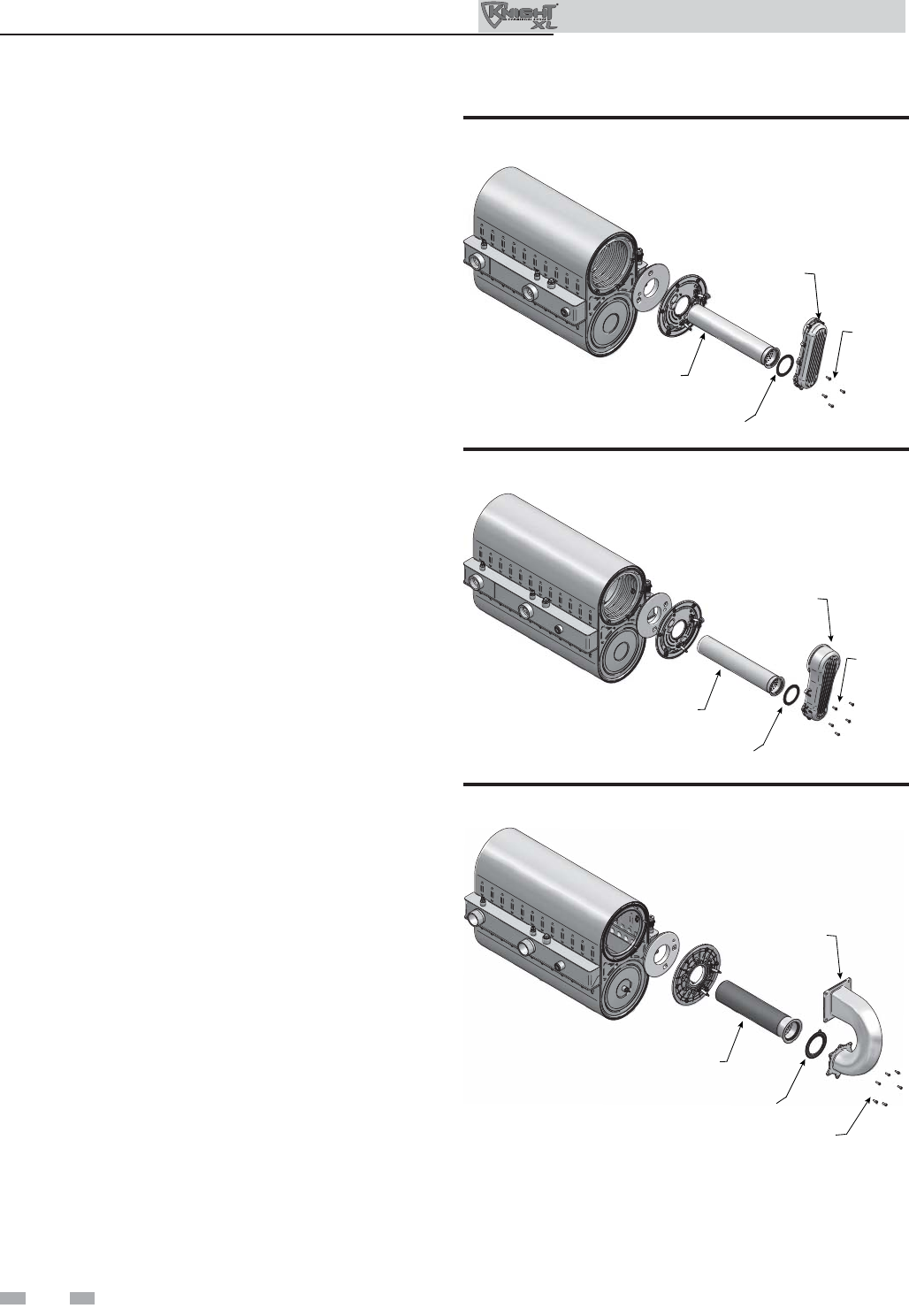
52
IMG00439
SCREWS
(5)
AIR / GAS
ARM
BURNER
GASKET
Figure 9-4 Burner Assembly - Models 601 - 801
9 Maintenance
Inspect ignition and fl ame sense
electrodes
1. Remove the ignition and fl ame sense electrodes from the
boiler heat exchanger access cover.
2. Remove any deposits accumulated on the ignition/fl ame
sense electrode using sandpaper. If the electrodes cannot
be cleaned satisfactorily, replace with new ones.
3. Replace ignition/fl ame sense electrode, making sure
gasket is in good condition and correctly positioned.
Check ignition ground wiring
1. Inspect boiler ground wire from the heat exchanger
access cover to ground terminal strip.
2. Verify all wiring is in good condition and securely
attached.
3. Check ground continuity of wiring using continuity
meter.
4. Replace ground wires if ground continuity is not
satisfactory.
Check all boiler wiring
1. Inspect all boiler wiring, making sure wires are in good
condition and securely attached.
Check control settings
1. Set the SMART SYSTEM control module display to
Parameter Mode and check all settings. See Section 1 of
the Outdoor Knight XL Service Manual. Adjust settings
if necessary. See Section 1 of the Outdoor Knight XL
Service Manual for adjustment procedures.
2. Check settings of external limit controls (if any) and
adjust if necessary.
Perform start-up and checks
1. Start boiler and perform checks and tests specifi ed in
Section 7 - Start-up.
2. Verify cold fi ll pressure is correct and that operating
pressure does not go too high.
Check burner fl ame
1. Inspect fl ame through observation window.
2. If the fl ame is unsatisfactory at either high fi re or low fi re,
turn off boiler and allow boiler to cool down. Remove
the burner and clean it thoroughly using a vacuum
cleaner or compressed air. Do not use compressed air to
clean burner if performed inside a building.
3. Remove the burner, reference FIG.’s 9-2 thru 9-4.
4. When replacing the burner, ensure gasket is in good
condition and positioned correctly (FIG.’s 9-2 thru 9-4).
IMG00437
BURNER
GASKET
SCREWS
(5)
AIR / GAS
ARM
Figure 9-2 Burner Assembly - Model 400
IMG00438
SCREWS
(5)
AIR / GAS
ARM
BURNER
GASKET
Figure 9-3 Burner Assembly - Model 501
Outdoor Knight XL Installation & Operation Manual
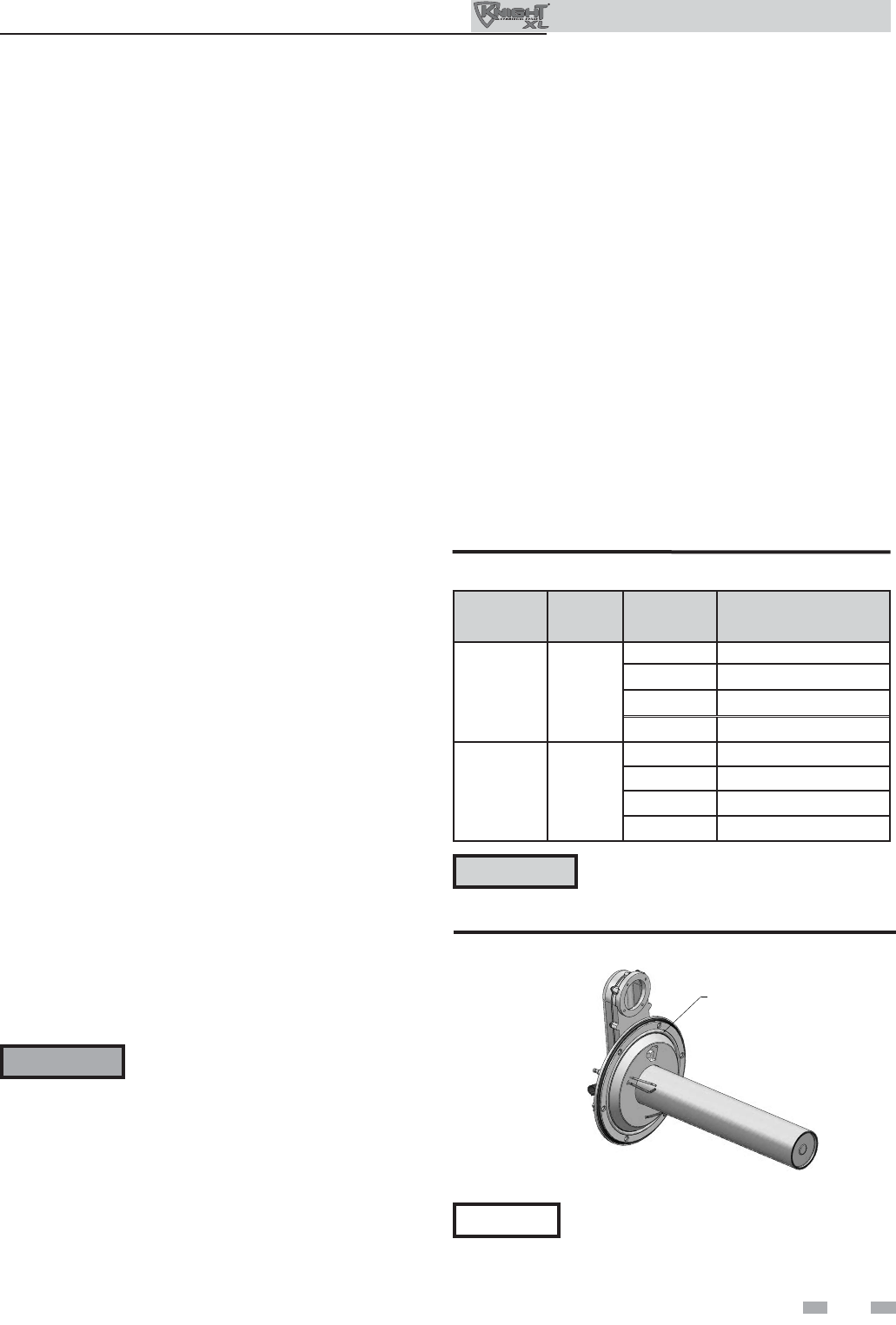
53
9 Maintenance (continued)
Check fl ame signal
1. At high fi re the fl ame signal shown on the display should
be at least 10 microamps.
2. A lower fl ame signal may indicate a fouled or damaged
fl ame sense electrode. If cleaning the fl ame sense electrode
does not improve, ground wiring is in good condition,
and ground continuity is satisfactory, replace the fl ame
sense electrode.
3. See Section 3 - Troubleshooting in the Outdoor Knight
XL Service Manual for other procedures to deal with low
fl ame signal.
Review with owner
1. Review the Outdoor Knight XL User’s Information
Manual with the owner.
2. Emphasize the need to perform the maintenance schedule
specifi ed in the Outdoor Knight XL User’s Information
Manual (and in this manual as well).
3. Remind the owner of the need to call a licensed contractor
should the boiler or system exhibit any unusual behavior.
4. Remind the owner to follow the proper shutdown
procedure and to schedule an annual start-up at the
beginning of the next heating season.
The boiler contains ceramic fiber
materials. Use care when handling these
materials per instructions in the Service
Manual. Failure to comply could result in
severe personal injury.
WARNING
Cleaning boiler heat exchanger
For recommended materials; including brush, appropriate
extension(s), refractory cover, and detailed instructions see
Table 9B - Heat Exchanger Cleaning Kits.
1. Shut down boiler:
• Follow the “To Turn Off Gas to Appliance” instructions
for the boiler in Section 7 - Startup.
• Do not drain the boiler unless it will be exposed to
freezing temperatures. If using freeze prevention fl uid
in system, do not drain.
2. Allow time for the boiler to cool to ambient temperature
if it has been fi ring.
3. Remove the nuts securing the heat exchanger access cover
to the heat exchanger and set aside.
4. Remove the heat exchanger access cover, burner, and
gas/air arm assembly.
6. Use a vacuum cleaner to remove any accumulation on the
boiler heating surfaces. Do not use any solvent.
7. Brush the heat exchanger while dry using a nylon bristle
brush. Caution: DO NOT use a metal brush. Re-vacuum
the heat exchanger.
8. Finish cleaning using a clean cloth dampened with warm
water. Rinse out debris with a low pressure water supply.
9. Allow the heat exchanger to thoroughly dry.
10. Remove the fi eld supplied rear refractory cover from the
back of the combustion chamber of the heat exchanger and
reassemble.
11. Close isolation valves on piping to isolate boiler from
system. Attach a hose to the boiler drain and fl ush boiler
thoroughly with clean water by using purging valves to
allow water to fl ow through the water make-up line to the
boiler.
12. Perform start-up and check-out procedures in the Check
Flame and Combustion - Section 7 - Startup on pages 35
and 37 of this manual.
13. Replace the access cover and restore boiler to operation.
Table 9B Heat Exchanger Cleaning Kits
Model
Kit
Number Part
Number Component
Description
400 KIT30063
CTN20005 Rear Refractory Cover
MSC20083* Nylon 4" Wheel Brush*
MSC20084 3mm Allen Wrench
MSC20086 1/4" x 24" Drill Extension
501 - 801 KIT30064
CTN20005 Rear Refractory Cover
MSC20083* Nylon 4" Wheel Brush*
MSC20085 1/4" x 12" Drill Extension
MSC20086 1/4" x 24" Drill Extension
* Do NOT use a metal brush. Only use
the kit provided brush or an equivalent
replacement nylon brush.
CAUTION
NOTICE Rope gasket is intended for sealing combustion
(FIG. 9-5). If damaged DO NOT reuse, the
heat exchanger door must be replaced. Consult
factory for replacement heat exchanger door
(kit WTR3080 and WTR3086).
ROPE GASKET
CAUTION: IF GASKET IS DAMAGED
DO NOT REUSE, THE HEAT EXCHANGER DOOR
MUST BE REPLACED.
Figure 9-5 Rope Gasket - Heat Exchanger Door
5. Remove the condensate hose from the heat exchanger
end. Connect a fi eld supplied 3/4" diameter hose to
a drain pan. Using fi eld supplied means, cover the
refractory in the back of the combustion chamber of the
heat exchanger.
Outdoor Knight XL Installation & Operation Manual
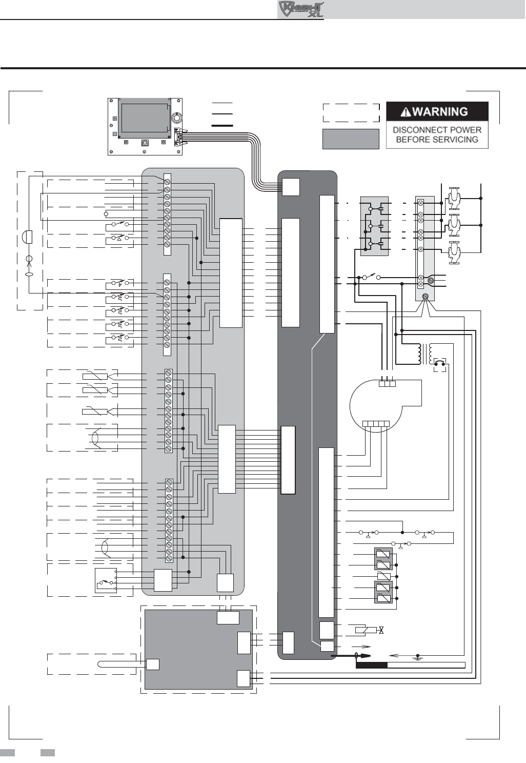
54
Figure 10-1 Wiring Diagram
10 Diagrams
X1-7
OR
OR
BR
PR
OR
BR
BR
PR
PR
CN2-4
CN2-1
CN1-5
CN1-6
CN1-3
CN1-4
CN1-1
CN1-2
K1
K2
K3
RELAY
BOARD
ON/OFF
SWITCH
JUNCTION
BOX
BK
W
1 2 3 4 5
G
R
RW3.5A
R
T
W
BK
Y
BL
KB 801
ONLY
BLOWER
-T
HIGH LIMIT SENSOR S1b
OPERATING SENSOR S1a
INLET SENSOR S2
FLUE SENSOR S3a
FLUE SENSOR S3b
INTEGRATED
CONTROL
BK
Y
GAS VALVE
@24VAC
SPARK
ROD
TRANSFORMER
TR2 G
HIGH VOLTAGE SPARK LEAD
CAUTION
FLAME SENSOR
P/BK
Y
W/R
X1-3
X1-4
X1-2
X1-6
X1-5
X1-8
X1-1
X5-7
X5-16
X5-8
X5-15
X5-9
X5-1
X5-2
X5-10
X5-11
X5-4
X5-12
X5-6
X5-5
X5-13
X5-14
X2-2
X2-1
O-TEMP HEX SW
BLOCKED DRAIN SWITCH
O
Notes:
1. All wiring must be installed in accordance with: local, state, provincial and national code requirements per either N.E.C. in USA or C.S.A. in Canada.
2. If any original equipment wire as supplied with the appliance must be replaced, it must be replaced with wire having same wire gauge (AWG) and rated for a
minimum of 105°C. Exceptions: Replacement high voltage spark lead and ribbon cables must be purchased from the factory. Use of a non-approved spark lead
or ribbon cables can lead to operational problems which could result in non-repairable damage to the integrated controller or other components.
3. Actual connector block locations may vary from those shown on diagrams. Refer to actual components for proper connector block locations when using
diagrams to troubleshoot unit. WIRING DIAGRAM
LBL20116 REV E
BOX DEPICTS
OPTIONAL ITEMS
CN2-2
CN2-3
DHW
PUMP
BOILER
PUMP
SYSTEM
PUMP
120V
SUPPLY
L
N
GND
LN
X-7
BOX DEPICTS
DUAL SENSOR
SINGLE HOUSING
MODBUS BOARD
MTR-01
X6-3
X6-2
X6-1
X6-4
X9-1
X9-2
X9-3
X9-4
X4-1
X4-2
X4-3
X4-4
X5-1
X5-2
X1-1
X1-2
X1-3
BK
W
G
RBLG
-T
-T
-T
-T
SHIELD
GROUNDING
JUMPER
O
GY
G
R/BK
W/BK
GY
PR
1 2
G
3
HIGH VOLTAGE
LOW VOLTAGE
120 VAC
AIR PRESSURE SWITCH
P
O/BK
ALARM
CONTACTS
RUN-TIME
CONTACTS
24 VAC LOUVER
RELAY COIL
LOUVER
PROVING SWITCH
GAS PRESSURE
SWITCH
FLOW
SWITCH
TANK
THERMOSTAT
11
12
13
14
15
16
17
18
19
20
SYSTEM
SENSOR
OUTDOOR
SENSOR
TANK
SENSOR
CASCADE A
B
SHIELD
SHIELD
0-10V
+
-
BMS
IN
0-10V
+
-
SYS PUMP
IN
0-10V
+
-
BLR PUMP
OUT
0-10V
+
-
RATE
OUT
MODBUS
OPTION
A
B
SHIELD
SHIELD
LOW
WATER
CUT-OFF
24 VAC
COM
1
2
3
4
5
6
7
8
9
10
21
22
23
24
25
26
27
28
29
30
31
32
33
34
35
36
37
38
39
40
41
42
43
44
CN7-1
CN7-2
CN7-3
CN7-4
CONNECTION BOARD
CN8-1
CN8-2
CN8-3
RBLG
BELL JUMPER
ALARM BELL
SILENCING SWITCH
HEAT/LOOP
DEMAND 3
HEAT/LOOP
DEMAND 2
HEAT/LOOP
DEMAND 1
CN5-1
CN5-8
CN5-2
CN5-9
CN5-3
CN5-10
CN5-11
CN5-4
CN5-5
CN5-14
CN5-12
CN5-6
CN5-13
CN5-7
BK
BK
BK
BK
BK
BK
BK
BK
BK
BK
BK
BK
BK
BK
CN6 X6
X4-7
X4-14
X4-6
X4-13
X4-5
X4-12
X4-11
X4-4
X4-3
X4-8
X4-10
X4-2
X4-9
X4-1
Outdoor Knight XL Installation & Operation Manual
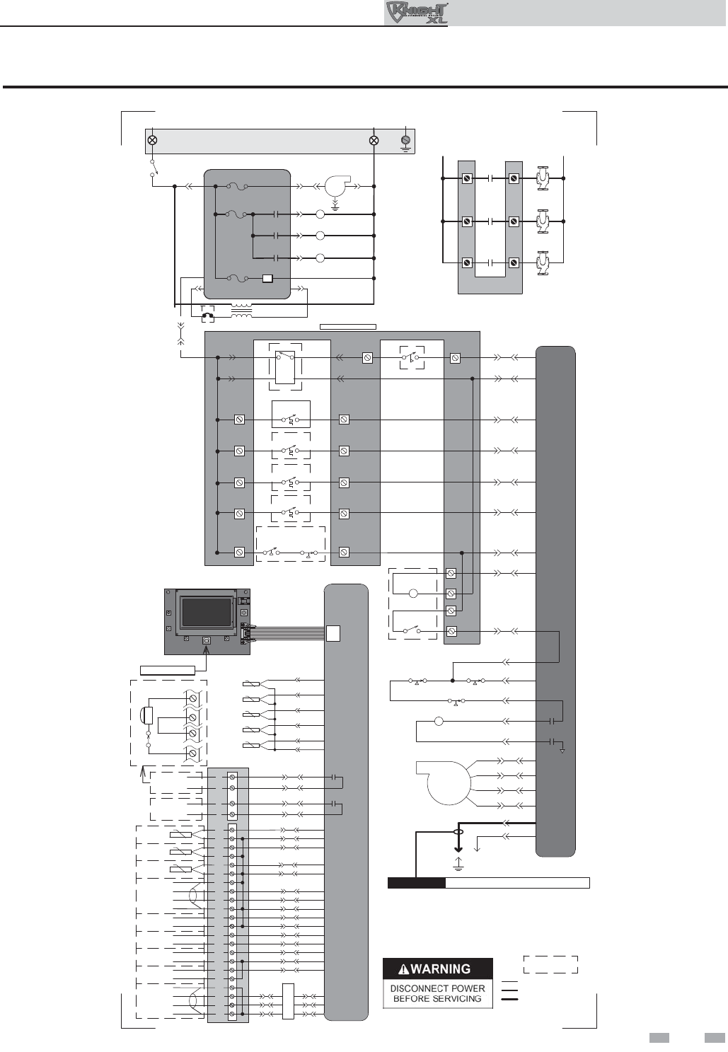
55
Figure 10-2 Ladder Diagram
BOX DEPICTS
OPTIONAL ITEMS
LADDER DIAGRAM
LBL20141 REV D
24 VAC
CN5-6
CN5-12
CN5-11
X4-2
X4-10
X4-11
INTEGRATED
CONTROL
LOUVER
RELAY COIL
24VAC
LOUVER
PROVING SWITCH CN5-4 X4-4
X2-1
GAS VALVE
GAS VALVE
RELAY
X5-7
X5-16
X5-8
X5-15
1
2
4
5
TR2
X1-7
FLAME ROD
SPARK
ROD
CAUTION HIGH VOLTAGE SPARK LEAD
BLOWER
CONNECTION
BOARD
INLET
SENSOR
OPERATING
SENSOR
FLUE
SENSOR
INTEGRATED
CONTROL
RUN-TIME
CONTACTS
RIBBON CABLE
X7
SYSTEM
SENSOR
TANK
SENSOR
OUTDOOR
SENSOR
0-10V
+
-
CASCADE A
B
SHIELD
SHIELD
13
6
2
1
SILENCING
SWITCH
ALARM
BELL
S6
S4
S5
BMS
CN6 X6
CN6 X6
CN6 X6
CN6 X6
CN6 X6
CN6 X6
CN6 X6
CN5-2 X4-6
CN5-9 X4-13
CN5-1 X4-7
CN5-8 X4-14
CN6 X6
CN6 X6
CN6 X6
HIGH LIMIT
SENSOR
FLUE
SENSOR
X5-4
X5-12
X5-5
X5-13
X5-14
X5-6
0-10V
+
-
SYS PUMP
IN
0-10V
+
-
BLR PUMP
OUT
0-10V
+
-
RATE
OUT
IN
MODBUS A
B
SHIELD
SHIELD
CN6 X6
CN6 X6
CN6 X6
CN6 X6
CN6 X6
CN8-1 X6-1
CN8-2 X6-2
CN8-3 X6-3
X4-1 X9-2
X4-2 X9-1
X4-3 X9-3
PC INTERFACE
S2
S1a
S1b
S3a
S3b
21
22
26
27
23
24
30
31
32
33
35
36
37
38
39
40
41
42
43
44
3
4
1
2
ALARM
CONTACTS
M
O
D
B
U
S
29
34
9
5
6
7
8
X2-2
NOTES:
1. Where possible, switches are shown without utilities (gas, water or
electricity) connected to the unit. As such, actual switch states may
vary from those shown on diagrams depending upon whether utilities
are connected or a fault condition is present.
2. See wiring diagram for additional notes.
CN5-3 X4-5
3.5A
KB 801
ONLY
CN5-13 X4-9
CN5-7 X4-1
11
CN5-10 X4-12
CN5-14 X4-8
CN5-5
X4-3
LOW VOLTAGE
120 VAC
HIGH VOLTAGE
X5-2
X5-11
X5-10
AIR PRESSURE
SWITCH
BLOCKED
DRAIN SWITCH
O-TEMP HEX SW
CONNECTION BOARD
19
17
15
13
10
LWCO
CN7-3
CN7-2
CN7-4
CN7-1
24 VAC
HEAT/LOOP
DEMAND
HEAT/LOOP
DEMAND
3
2
1
HEAT/LOOP
DEMAND
TANK
THERMOSTAT
HIGH GAS
PRESSURE
SWITCH
LOW GAS
PRESSURE
SWITCH
20
18
16
14
9
12
FLOW
SWITCH
120 VAC
120VAC
TERMINAL STRIP
120V SUPPLY "L"
ON / OFF
SWITCH
X1-6
X1-2
F2
NEUTRAL
TERMINAL STRIP
120V SUPPLY "N"
3.15A
F1
5A
INTEGRATED CONTROL
GROUND
JUNCTION BOX
BOILER
PUMP
DHW
PUMP
SYSTEM
PUMP
BOILER
PUMP
CONTACTS
DHW
PUMP
CONTACTS
SYSTEM
PUMP
CONTACTS
L
IN
L
OUT
RELAY BOARD
X1-1 12
BLOWER
SYSTEM PUMP
RELAY
DHW PUMP
RELAY
BOILER PUMP
RELAY
SYSTEM PUMP
RELAY
DHW PUMP
RELAY
BOILER PUMP
RELAY
24V DC
SUPPLY
F3
.8A
X5-1
X5-9
X1-3
X1-4
3
10 Diagrams (continued)
Outdoor Knight XL Installation & Operation Manual

Revision Notes: Revision A (ECO #C11234) initial release.
Revision B (ECO #C11235) refl ects updates made to the freezing
conditions warnings.
OKBX-I-O Rev B
10/12
