Lochinvar Knight 51 Users Manual WBII I O Rev C
51 to the manual 7a8581af-a56f-4bde-a000-fca0a5a6ee53
2015-02-09
: Lochinvar Lochinvar-Knight-51-Users-Manual-575400 lochinvar-knight-51-users-manual-575400 lochinvar pdf
Open the PDF directly: View PDF ![]() .
.
Page Count: 80

WBII-I-O Rev C
Installation & Operation Manual
Models: 51 - 211
This manual must only be used by a
qualified heating installer / service
technician. Read all instructions,
including this manual and the Knight
Wall Mount Service Manual, before
installing. Perform steps in the order
given. Failure to comply could result
in severe personal injury, death, or
substantial property damage.
WARNING
Save this manual for future reference.

2
Hazard definitions
The following defined terms are used throughout this manual to bring attention to the presence of hazards of various risk levels or
to important information concerning the life of the product.
DANGER
WARNING
CAUTION
CAUTION
NOTICE
DANGER indicates an imminently hazardous situation which, if not avoided, will result in death or serious
injury.
WARNING indicates a potentially hazardous situation which, if not avoided, could result in death or serious
injury.
CAUTION indicates a potentially hazardous situation which, if not avoided, may result in minor or moderate
injury.
CAUTION used without the safety alert symbol indicates a potentially hazardous situation which, if not
avoided, may result in property damage.
NOTICE indicates special instructions on installation, operation, or maintenance that are important but not
related to personal injury or property damage.
HAZARD DEFINITIONS . . . . . . . . . . . . . . . . . . . . . . . . . . 2
PLEASE READ BEFORE PROCEEDING . . . . . . . . . . . . 3
THE KNIGHT WALL MOUNT BOILER--HOW IT WORKS . . . 4-5
RATINGS . . . . . . . . . . . . . . . . . . . . . . . . . . . . . . . . . . . . . . 6
1. DETERMINE BOILER LOCATION
Provide Clearances . . . . . . . . . . . . . . . . . . . . . . . . . . . . . . 7
Provide Air Openings to Room . . . . . . . . . . . . . . . . . . . . . 9
Wall Mounting Location . . . . . . . . . . . . . . . . . . . . . . . . . . 9
Residential Garage Installation . . . . . . . . . . . . . . . . . . . . . 9
Vent and Air Piping . . . . . . . . . . . . . . . . . . . . . . . . . . . . . . 9
Prevent Combustion Air Contamination . . . . . . . . . . . . . . . 9
Corrosive Contaminants and Sources . . . . . . . . . . . . . . . 10
Using an Existing Vent System to Install a New Boiler . . 10
Removing a Boiler from Existing Common Vent . . . . . . . 11
2. PREPARE BOILER
Remove Boiler from Wood Pallet . . . . . . . . . . . . . . . . . . 12
Gas Conversions . . . . . . . . . . . . . . . . . . . . . . . . . . . . . . . 12
Mounting the Boiler . . . . . . . . . . . . . . . . . . . . . . . . . . . . . 13
3. GENERAL VENTING
Direct Venting Options . . . . . . . . . . . . . . . . . . . . . . . . . . . 14-15
Install Vent and Combustion Air Piping . . . . . . . . . . . . . . 16
PVC/CPVC Vent Piping Materials . . . . . . . . . . . . . . . 16
Requirements for Installation in Canada . . . . . . . . . . . . . 16
PVC/CPVC Air Intake/Vent Connections . . . . . . . . . . . . . 17
Air Inlet Pipe Materials . . . . . . . . . . . . . . . . . . . . . . . . . . 17
Stainless Steel Vent . . . . . . . . . . . . . . . . . . . . . . . . . . . . . 18
Max. Allowable Vent Piping Lengths . . . . . . . . . . . . . . . . 19
Vent and Air Piping . . . . . . . . . . . . . . . . . . . . . . . . . . . . . 19
Optional Room Air . . . . . . . . . . . . . . . . . . . . . . . . . . . . . . 20
4. SIDEWALL DIRECT VENTING
Vent/Air Termination - Sidewall . . . . . . . . . . . . . . . . . . . . 21-24
Determine Location . . . . . . . . . . . . . . . . . . . . . . . . . . 21-22
Prepare Wall Penetrations . . . . . . . . . . . . . . . . . . . . . 23
Termination and Fittings . . . . . . . . . . . . . . . . . . . . . . . 23
Multiple Vent/Air Terminations . . . . . . . . . . . . . . . . . . . . . 23-24
Sidewall Termination - Optional Concentric Vent . . . . . . 24-26
5. VERTICAL DIRECT VENTING
Vent/Air Termination - Vertical . . . . . . . . . . . . . . . . . . . . . 27-28
Determine Location . . . . . . . . . . . . . . . . . . . . . . . . . . 27
Prepare Roof Penetrations . . . . . . . . . . . . . . . . . . . . . 28
Termination and Fittings . . . . . . . . . . . . . . . . . . . . . . . . . 28
Multiple Vent/Air Terminations . . . . . . . . . . . . . . . . . . . . . 28
Vertical Termination - Optional Concentric Vent . . . . . . . 29-30
Optional Vertical Concentric Venting . . . . . . . . . . . . . . . . 31-32
6. HYDRONIC PIPING
System Water Piping Methods . . . . . . . . . . . . . . . . . . . . 33
Low Water Cutoff Device . . . . . . . . . . . . . . . . . . . . . . . . . 33
Chilled Water System . . . . . . . . . . . . . . . . . . . . . . . . . . . 33
Freeze Protection . . . . . . . . . . . . . . . . . . . . . . . . . . . . . . 33
General Piping Information . . . . . . . . . . . . . . . . . . . . . . . 33
Near Boiler Piping Components . . . . . . . . . . . . . . . . . . . 34
Near Boiler Piping Connections . . . . . . . . . . . . . . . . . . . 35
Circulator Sizing . . . . . . . . . . . . . . . . . . . . . . . . . . . . . . . 35
Variable Speed Pump Option . . . . . . . . . . . . . . . . . . . . . 37
7. GAS CONNECTIONS
Connecting Gas Supply Piping . . . . . . . . . . . . . . . . . . . . 46
Natural Gas . . . . . . . . . . . . . . . . . . . . . . . . . . . . . . . . . . . 47
Pipe Sizing for Natural Gas . . . . . . . . . . . . . . . . . . . . 47
Natural Gas Supply Pressure Requirements . . . . . . . 47
Propane Gas . . . . . . . . . . . . . . . . . . . . . . . . . . . . . . . . . . 47
Pipe Sizing for Propane Gas . . . . . . . . . . . . . . . . . . . 47
Propane Supply Pressure Requirements . . . . . . . . . . 47
Check Inlet Gas Supply . . . . . . . . . . . . . . . . . . . . . . . . . . 48
Gas Pressure . . . . . . . . . . . . . . . . . . . . . . . . . . . . . . . . . . 49
Gas Valve Replacement . . . . . . . . . . . . . . . . . . . . . . . . . 49
8. FIELD WIRING
Line Voltage Connections . . . . . . . . . . . . . . . . . . . . . . . . 50
Low Voltage Connections . . . . . . . . . . . . . . . . . . . . . . . . 50
Wiring of the Cascade . . . . . . . . . . . . . . . . . . . . . . . . . . . 52
9. CONDENSATE DISPOSAL
Condensate Drain . . . . . . . . . . . . . . . . . . . . . . . . . . . . . . 54
10. STARTUP . . . . . . . . . . . . . . . . . . . . . . . . . . . . . . . . . 55-60
11. OPERATING INFORMATION
General . . . . . . . . . . . . . . . . . . . . . . . . . . . . . . . . . . . . . . 61
Cascade . . . . . . . . . . . . . . . . . . . . . . . . . . . . . . . . . . . . . . 64
Sequence of Operation . . . . . . . . . . . . . . . . . . . . . . . . . . 65-66
Knight Wall Mount Boiler Control Module . . . . . . . . . . . . 67
Status Display Screens . . . . . . . . . . . . . . . . . . . . . . . . . . 68-70
12. MAINTENANCE
Maintenance and Annual Startup . . . . . . . . . . . . . . . . . . 71-74
13. DIAGRAMS
Ladder Diagram . . . . . . . . . . . . . . . . . . . . . . . . . . . . . . . . 75
Wiring Diagram . . . . . . . . . . . . . . . . . . . . . . . . . . . . . . . . 76
Revision Notes . . . . . . . . . . . . . . . . . . . . . . . . . Back Cover
Contents
Installation & Operation Manual
Please read before proceeding
Installer – Read all instructions,
including this manual and the Knight
Wall Mount Service Manual, before
installing. Perform steps in the order
given.
User – This manual is for use only by a
qualified heating installer/service
technician. Refer to the User’s
Information Manual for your reference.
Have this boiler serviced/inspected by a
qualified service technician, at least
annually.
Failure to comply with the above could
result in severe personal injury, death or
substantial property damage.
Failure to adhere to the guidelines on this
page can result in severe personal injury,
death, or substantial property damage.
When servicing boiler –
• To avoid electric shock, disconnect electrical supply
before performing maintenance.
• To avoid severe burns, allow boiler to cool before
performing maintenance.
Boiler operation –
• Do not block flow of combustion or ventilation air to
the boiler.
• Should overheating occur or gas supply fail to shut off,
do not turn off or disconnect electrical supply to
circulator. Instead, shut off the gas supply at a location
external to the appliance.
• Do not use this boiler if any part has been under water.
The possible damage to a flooded appliance can be
extensive and present numerous safety hazards. Any
appliance that has been under water must be replaced.
Boiler water –
• Thoroughly flush the system (without boiler
connected) to remove sediment. The high-efficiency
heat exchanger can be damaged by build-up or
corrosion due to sediment.
• Continual fresh make-up water will reduce boiler life.
Mineral buildup in the heat exchanger reduces heat
transfer, overheats the stainless steel heat exchanger,
and causes failure. Addition of oxygen carried in by
makeup water can cause internal corrosion in system
components. Leaks in boiler or piping must be repaired
at once to prevent makeup water.
Freeze protection fluids –
• NEVER use automotive antifreeze. Use only inhibited
propylene glycol solutions, which are specifically
formulated for hydronic systems. Ethylene glycol is
toxic and can attack gaskets and seals used in hydronic
systems.
When calling or writing about the boiler –
Please have the boiler model and serial
number from the boiler rating plate.
Consider piping and installation when
determining boiler location.
Any claims for damage or shortage in
shipment must be filed immediately
against the transportation company by
the consignee.
Factory warranty (shipped with unit)
does not apply to units improperly
installed or improperly operated.
3
If the information in this manual is not
followed exactly, a fire or explosion may
result causing property damage, personal
injury or loss of life.
This appliance MUST NOT be installed
in any location where gasoline or
flammable vapors are likely to be present.
WHAT TO DO IF YOU SMELL GAS
• Do not try to light any appliance.
• Do not touch any electric switch; do
not use any phone in your building.
• Immediately call your gas supplier
from a near by phone. Follow the
gas supplier’s instructions.
• If you cannot reach your gas supplier,
call the fire department.
• Installation and service must be
performed by a qualified installer,
service agency, or the gas supplier.
WARNING
NOTICE
WARNING
WARNING Do not use petroleum-based cleaning or
sealing compounds in the boiler system.
Gaskets and seals in the system may be
damaged. This can result in substantial
property damage.
CAUTION
CAUTION Do not use “homemade cures” or “boiler
patent medicines”. Serious damage to
the boiler, personnel, and/or property
may result.

Installation & Operation Manual
4
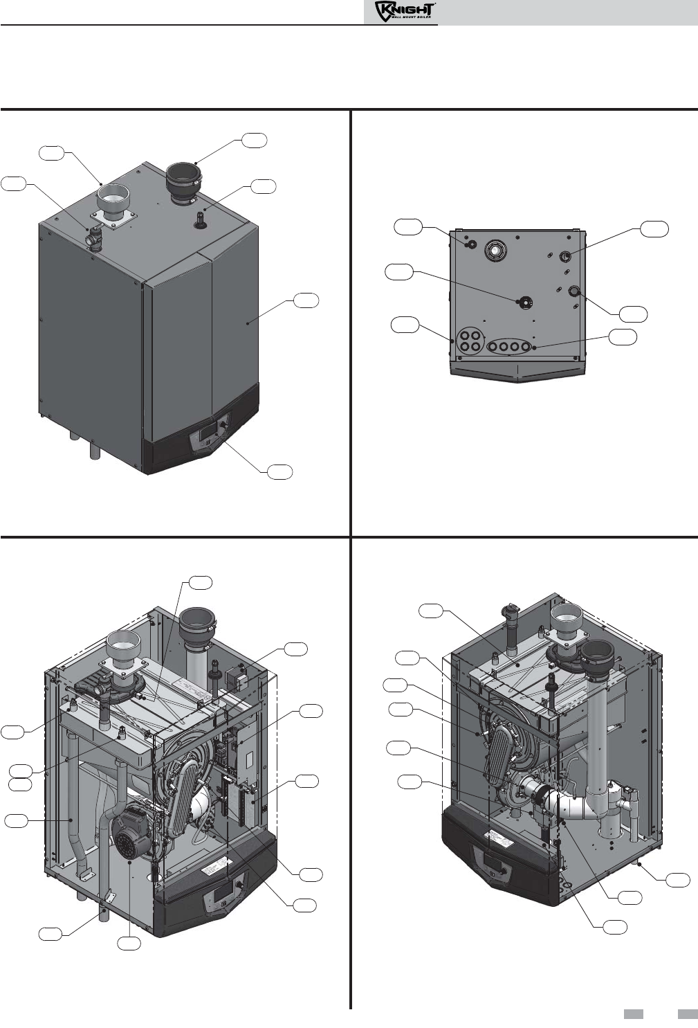
The Knight Wall Mount Boiler - How it works...
1. Stainless steel heat exchanger
Allows system water to flow through specially designed
coils for maximum heat transfer, while providing
protection against flue gas corrosion. The coils are
encased in a jacket that contains the combustion process.
2. Combustion chamber access cover
Allows access to the combustion side of the heat
exchanger coils.
3. Blower
The blower pulls in air and gas through the venturi (item
5). Air and gas mix inside the blower and are pushed into the
burner, where they burn inside the combustion chamber.
4. Gas valve
The gas valve senses the negative pressure created by the
blower, allowing gas to flow only if the gas valve is
powered and combustion air is flowing.
5. Venturi
The venturi controls air and gas flow into the burner.
6. Flue gas sensor (limit rated)
This sensor monitors the flue gas exit temperature. The control
module will modulate and shut down the boiler if flue gas
temperature gets too hot. This protects the flue pipe from
overheating.
7. Boiler outlet temperature sensor (housed with high
limit sensor)
This sensor monitors boiler outlet water temperature (system
supply). If selected as the controlling sensor, the control
module adjusts boiler firing rate so the outlet temperature is
correct.
8. Boiler inlet temperature sensor
This sensor monitors return water temperature (system
return). If selected as the controlling sensor, the control
module adjusts the boiler firing rate so the inlet temperature is
correct.
9. Temperature and pressure gauge (field installed, not
shown)
Monitors the outlet temperature of the boiler as well as the
system water pressure.
10. Electronic LCD display
The electronic display consists of 4 buttons, a navigation dial
and a multiple line liquid crystal display.
11. Flue pipe adapter
Allows for the connection of the PVC vent pipe system to the
boiler.
12. Burner (not shown)
Made with metal fiber and stainless steel construction,
the burner uses pre-mixed air and gas and provides a
wide range of firing rates.
13. Water outlet (system supply)
The water outlet is the water connection for water leaving the
boiler and entering the system. Boiler connection is 1".
14. Water inlet (system return)
The water inlet is the water connection for water entering the
boiler from the system. Boiler connection is 1".
15. Gas connection pipe
Threaded pipe connection of 1/2". This pipe should be
connected to the incoming gas supply for the purpose of
delivering gas to the boiler.
16. SMART SYSTEM Control Module
The SMART SYSTEM Control responds to internal and
external signals and controls the blower, gas valve, and pumps
to meet the heating demand.
17. Air intake adapter
Allows for the connection of the PVC air intake pipe to
the boiler.
18. High voltage junction box
The junction box contains the connection points for the line
voltage power and all pumps.
19. Manual air vent
Designed to remove trapped air from the heat exchanger
coils.
20. Low voltage connection board
The connection board is used to connect external low voltage
devices.
21. Low voltage wiring connections (knockouts)
Conduit connection points for the low voltage
connection board.
22. Condensate drain connection
Connects the condensate drain line to a 1/2" pipe.
23. Access door
Provides access to all internal components.
24. Ignition electrode
Provides direct spark for igniting the burner.
25. Flame inspection window
The quartz glass window provides a view of the burner
surface and flame.
26. Gas shutoff switch
An electrical switch designed to cut power to the gas valve to
prevent releasing any gas.
27. High limit sensor (housed with outlet sensor)
Device that monitors the outlet water temperature. If the
temperature exceeds its setting, it will break the control circuit,
shutting the boiler down.
28. Relief valve
Protects the heat exchanger from an over pressure condition.
The relief valve provided with the unit is set at 30 psi.
29. Flame sensor
Used by the control module to detect the presence of burner
flame.
30. Line voltage wiring connections (knockouts)
Conduit connection points for the high voltage junction box.
31. Air pressure switch
The air pressure switch detects blocked inlet conditions.
32. Transformer
The transformer provides 24V power to the integrated control.
Installation & Operation Manual
11
17
19
23
10
28
Front View
16
32
20
29
31
3
13
14
7
27
8
6
Left Side (inside unit)
2
25
24
5
4
26
22
18
1
Right Side (inside unit)
The Knight Wall Mount Boiler - How it works... (continued)
FRONT
OF UNIT
14
13
30
21
15
22
Bottom View
5
Models 51 - 211
6
Installation & Operation Manual
Ratings
Notes:
1. As an Energy Star Partner, Lochinvar has determined that
Knight wall mount boilers meet the Energy Star guidelines
for energy efficiency.
2. The ratings are based on standard test procedures prescribed
by the United States Department of Energy.
3. Net I=B=R ratings are based on net installed radiation of
sufficient quantity for the requirements of the building and
nothing need be added for normal piping and pickup.
Ratings are based on a piping and pickup allowance of 1.15.
4. Knight wall mount boilers require special gas venting. Use
only the vent materials and methods specified in the Knight
Wall Mount Installation and Operation Manual.
5. Standard Knight wall mount boilers are equipped to operate
from sea level to 4,500 feet only with no adjustments. The
boiler will de-rate by 4% for each 1,000 feet above sea level
up to 4,500 feet.
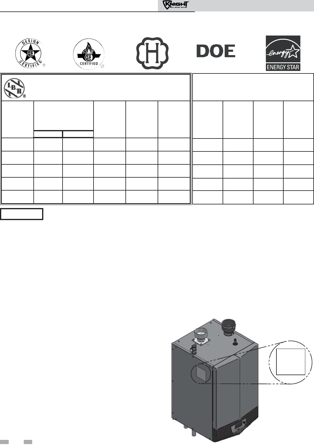
6. High altitude Knight wall mount boilers are equipped to
operate from 3,000 to 12,000 feet only with no field
adjustments. The boiler will de-rate by 2% for each 1,000
feet above 3,000 feet. High altitude models are
manufactured with a different control module for altitude
operation, but the operation given in this manual remains
the same as the standard boilers. A high altitude label (as
shown in FIG. A) is also affixed to the unit.
Maximum allowed working pressure is located on the rating plate.
NOTICE
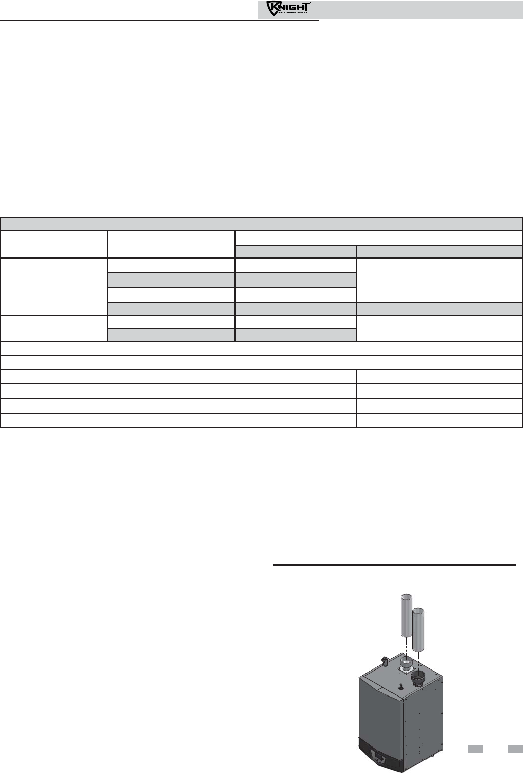
Knight Wall Mount Boiler
I=B=R Rating
Model
Number
Note: Change
“N” to “L” for L.P.
gas models.
Input
MBH
(Note 5)
Min Max
Heating
Capacity
MBH
(Note 2, 8
Net
I=B=R
Ratings
Water,
MBH
(Note 3, 8)
AFUE
%
(Note 1, 8)
WBN051 10 50 45 39 95.3
WBN081 16 80 72 63 95.3
WBN106 21 105 94 82 95.4
WBN151 30 150 135 119 95.5
WBN211 42 210 190 165 95.7
7. The Knight Wall Mount boiler input rate, on some
models, is reduced for vent lengths beyond the
minimum. Models WB(N,L)081 and WB(N,L)106 with
2" vent will reduce 1% for every 10 feet of vent. Models
WB(N,L)151 and WB(N,L)211 with 3" vent will reduce
0.5% for every 10 feet of vent.
8. Ratings have been confirmed by the Hydronics Institute,
Section of AHRI.
9. Knight wall mount boilers comply with the requirements
of CSD-1 Section CW-400 requirements as a temperature
operation control. The manual reset high limit provided
with the Knight is listed to UL353.
Other Specifications
Boiler Water
Content
Gallons
Water
Connections
Gas
Connections
Vent/Air Size
(Note 4)
0.6 1" 1/2" 2"
0.6 1" 1/2" 2"
0.7 1" 1/2" 2"
1.3 1" 1/2" 3"
1.7 1" 1/2" 3"
Figure A High Altitude Label Location
UNIT EQUIPPED FOR
HIGH ALTITUDE
3,000 FT. TO 12,000 FT.
The Knight wall mount boiler gas
manifold and controls met safe lighting
and other performance criteria when the
boiler underwent tests specified in ANSI
Z21.13 – latest edition.
Failure to keep boiler area clear and free of
combustible materials, gasoline, and other
flammable liquids and vapors can result in
severe personal injury, death, or
substantial property damage.
Installation must comply with:
• Local, state, provincial, and national codes, laws,
regulations, and ordinances.
• National Fuel Gas Code, ANSI Z223.1 – latest edition.
• Standard for Controls and Safety Devices for
Automatically Fired Boilers, ANSI/ASME CSD-1, when
required.
• National Electrical Code.
• For Canada only: B149.1 Installation Code, CSA C22.1
Canadian Electrical Code Part 1 and any local codes.
Before locating the boiler, check:
1. Check for nearby connection to:
• System water piping
• Venting connections
• Gas supply piping
• Electrical power
2. Locate the appliance so that if water connections should
leak, water damage will not occur. When such locations
cannot be avoided, it is recommended that a suitable
drain pan, adequately drained, be installed under the
appliance. The pan must not restrict combustion air
flow. Under no circumstances is the manufacturer to be
held responsible for water damage in connection with
this appliance, or any of its components.
3. Check area around the boiler. Remove any combustible
materials, gasoline and other flammable liquids.
4. The Knight wall mount boiler must be installed so that
gas control system components are protected from
dripping or spraying water or rain during operation or
service.
5. If a new boiler will replace an existing boiler, check for
and correct system problems, such as:
• System leaks causing oxygen corrosion or heat
exchanger cracks from hard water deposits.
• Incorrectly-sized expansion tank.
• Lack of freeze protection in boiler water causing system
and boiler to freeze and leak.
WARNING This appliance is certified as an indoor
appliance. Do not install the appliance
outdoors or locate where the appliance will
be exposed to freezing temperatures or to
temperatures that exceed 100°F.
Failure to install the appliance indoors
could result in severe personal injury,
death, or substantial property damage.
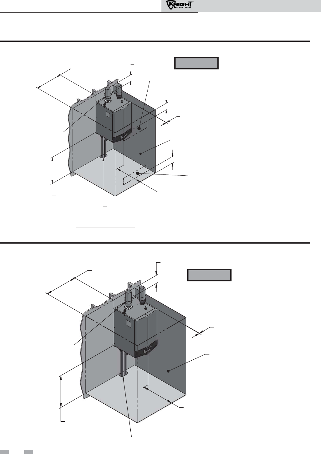
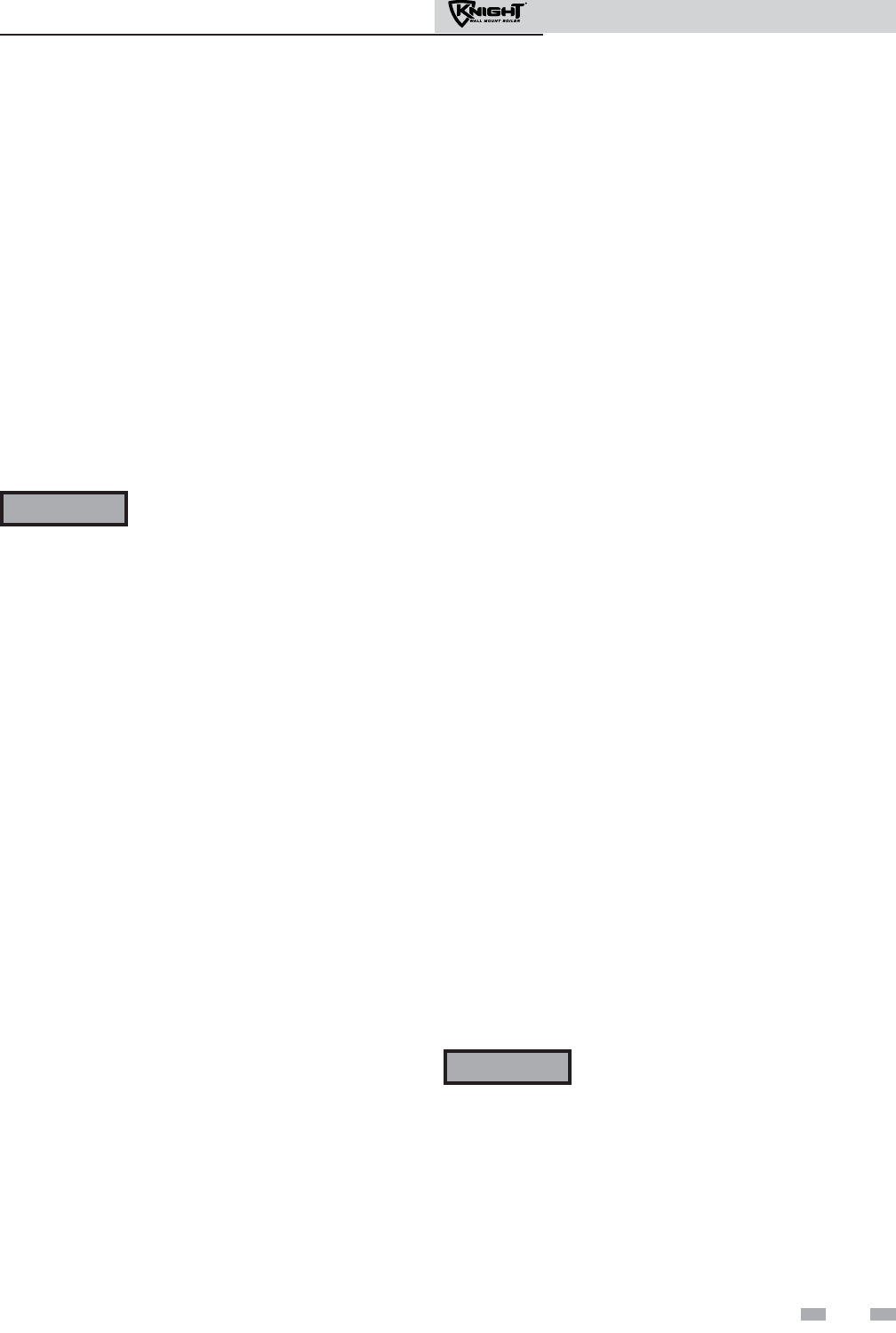
Provide clearances:
Clearances from combustible materials
1. Hot water pipes—at least 1" from combustible materials.
2. Vent pipe – at least 1" from combustible materials.
3. See FIG.’s 1-1 and 1-2 on page 8 for other clearance
minimums.
Clearances for service access
1. See FIG.’s 1-1 and 1-2 on page 8 for recommended
service clearances. If you do not provide the minimum
clearances shown, it may not be possible to service the
boiler without removing it from the space.
Closet and alcove installations
This appliance requires a special venting
system. The vent connection to the
appliance is made of CPVC. Field supplied
vent fittings must be cemented to the
CPVC fitting on the boiler. Use only the
vent materials, primer, and cement
specified in the manual to make the vent
connections. Failure to follow this
warning could result in fire, personal
injury, or death.
For closet and alcove installations as
shown in FIG.’s 1-1 and 1-2, CPVC or
stainless steel vent material must be used
inside the structure. The two ventilating
air openings shown in FIG. 1-1 are
required for this arrangement. Failure to
follow this warning could result in fire,
personal injury, or death.
WARNING
WARNING
NOTICE
WARNING
A closet is any room the boiler is installed in which is less than
79 cubic feet for WBN051 through WBN106 models,
104 cubic feet for WBN151 models, and 125 cubic feet for
WBN211 models.
An alcove is any room which meets the criteria for a closet
with the exception that it does not have a door.
Example: Room dimensions = 4 feet long, 4 feet wide, and
9 foot ceiling = 4 x 4 x 9 = 144 cubic feet. This would be
considered a closet for a Knight wall mount boiler.
7
1 Determine boiler location
Installation & Operation Manual
TOP
6" MINIMUM
LEFT
24" SERVICE
0" MINIMUM
FRONT
24" SERVICE
6" MINIMUM
BOTTOM
24" SERVICE
0" MINIMUM
1" MINIMUM CLEARANCE
AROUND HOT WATER PIPES
1" MINIMUM CLEARANCE
A
ROUND VENT PIPE OPEN FRONT
RIGHT
0" MINIMUM
Figure 1-2 Alcove Installation - Minimum Required Clearances
TOP
6" MINIMUM
LEFT
24" SERVICE
0" MINIMUM
BOTTOM
24" SERVICE
0" MINIMUM
1" MINIMUM CLEARANCE
AROUND HOT WATER PIPES
1" MINIMUM CLEARANCE
A
ROUND VENT PIPE CLOSED DOOR
FRONT
24" SERVICE
6" MINIMUM
6"
6"
VENTILATING
AIR OPENING*
*AREA OF EACH OPENING:
1 SQ. INCH PER 1000 BTU PER HOUR INPUT
WITH A MINIMUM OF 100 SQ. INCHES.
VENTILATING
AIR OPENING*
RIGHT
0" MINIMUM
Figure 1-1 Closet Installation - Minimum Required Clearances
WARNING For closet installations, CPVC or
stainless steel vent material MUST
BE used in a closet structure due to
elevated temperatures. Failure to
follow this warning could result in
fire, personal injury, or death.
Note: Service clearances are recommendations only.
Note: Service clearances are recommendations only.
WARNING For alcove installations, CPVC or
stainless steel vent material MUST
BE used in an alcove structure due
to elevated temperatures. Failure
to follow this warning could result
in fire, personal injury, or death.
8
1 Determine boiler location
Installation & Operation Manual
Provide air openings to room:
Knight wall mount boiler alone in boiler room
1. No air ventilation openings into the boiler room are
needed when clearances around the Knight wall mount
boiler are at least equal to the SERVICE clearances
shown in FIG.’s 1-1 and 1-2. For spaces that do NOT
supply this clearance, provide two openings as shown
in FIG. 1-1. Each opening must provide one square
inch free area per 1,000 Btu/hr of boiler input.
Knight wall mount boiler in same space with other
gas or oil-fired appliances
1. Follow the National Fuel Gas Code (U.S.) or CSA
B149.1 (Canada) to size/verify size of the
combustion/ventilation air openings into the space.
The space must be provided with
combustion/ventilation air openings
correctly sized for all other appliances
located in the same space as the Knight
wall mount boiler.
Do not install the boiler in an attic.
Failure to comply with the above
warnings could result in severe personal
injury, death, or substantial property
damage.
2. Size openings only on the basis of the other appliances
in the space. No additional air opening free area is
needed for the Knight wall mount boiler because it
takes its combustion air from outside (direct vent
installation).
Wall mounting location
Ensure the wall for which the boiler is intended to be
mounted is comprised of either, cement, brick, block, or
wooden studs spaced 16" apart from center. Ensure the wall
is capable of supporting at least 200 pounds.
If flooding is possible, elevate the boiler sufficiently to
prevent water from reaching the boiler.
Ensure the boiler is installed in a location that minimizes
the risk of water damage due to valves, pumps, etc.
Residential garage installation
Precautions
Take the following precautions when installing the appliance in
a residential garage. If the appliance is located in a residential
garage, it should be installed in compliance with the latest
edition of the National Fuel Gas Code, ANSI Z223.1 and/or
CAN/CGA-B149 Installation Code.
• Appliances located in residential garages and in
adjacent spaces that open to the garage and are not part
of the living space of a dwelling shall be installed so that
all burners and burner ignition devices are located not
less than 18 inches (46 cm) above the floor.
• The appliance shall be located or protected so that it is
not subject to physical damage by a moving vehicle.
Vent and air piping
The Knight wall mount boiler requires a special vent system,
designed for pressurized venting.
The boiler is to be used for either direct vent installation or for
installation using indoor combustion air. When room air is
considered, see Section 3, General Venting. Note prevention of
combustion air contamination below when considering vent/air
termination.
Vent and air must terminate near one another and may be
vented vertically through the roof or out a side wall, unless
otherwise specified. You may use any of the vent/air piping
methods covered in this manual. Do not attempt to install the
Knight wall mount boiler using any other means.
Be sure to locate the boiler such that the vent and air piping can
be routed through the building and properly terminated. The
vent/air piping lengths, routing and termination method must
all comply with the methods and limits given in this manual.
Prevent combustion air contamination
Install air inlet piping for the Knight wall mount boiler as
described in this manual. Do not terminate vent/air in locations
that can allow contamination of combustion air. Refer to Table
1A, page 10 for products and areas which may cause
contaminated combustion air.
You must pipe combustion air to the boiler
air intake. Ensure that the combustion air
will not contain any of the contaminants in
Table 1A, page 10. Contaminated
combustion air will damage the boiler,
resulting in possible severe personal injury,
death or substantial property damage. Do
not pipe combustion air near a swimming
pool, for example. Also, avoid areas subject
to exhaust fumes from laundry facilities.
These areas will always contain
contaminants.
WARNING
WARNING
1 Determine boiler location (continued)
9
Installation & Operation Manual
Products to avoid:
Spray cans containing chloro/fluorocarbons
Permanent wave solutions
Chlorinated waxes/cleaners
Chlorine-based swimming pool chemicals
Calcium chloride used for thawing
Sodium chloride used for water softening
Refrigerant leaks
Paint or varnish removers
Hydrochloric acid/muriatic acid
Cements and glues
Antistatic fabric softeners used in clothes dryers
Chlorine-type bleaches, detergents, and cleaning solvents
found in household laundry rooms
Adhesives used to fasten building products and other
similar products
Areas likely to have contaminants
Dry cleaning/laundry areas and establishments
Swimming pools
Metal fabrication plants
Beauty shops
Refrigeration repair shops
Photo processing plants
Auto body shops
Plastic manufacturing plants
Furniture refinishing areas and establishments
New building construction
Remodeling areas
Garages with workshops
Table 1A Corrosive Contaminants and Sources
Failure to follow all instructions can result
in flue gas spillage and carbon monoxide
emissions, causing severe personal injury
or death.
WARNING
When using an existing vent system to
install a new boiler:
Check the following venting components before installing:
•Material- For materials listed for use with this appliance,
see Section 3 - General Venting, Table 3A. For stainless
steel venting, an adapter of the same manufacturer
(Table 3B) must be used at the flue collar connection.
•Size- To ensure proper pipe size is in place, see Table 3C.
Check to see that this size is used throughout the vent
system.
• Manufacturer - For a stainless steel application, you
must use only the listed manufacturers and their type
product listed in Table 3A for CAT IV positive pressure
venting with flue producing condensate.
•Supports- Non-combustible supports must be in place
allowing a minimum 1/4" rise per foot. The supports
should adequately prevent sagging and vertical slippage,
by distributing the vent system weight. For additional
information, consult the vent manufacturer’s
instructions for installation.
• Terminations - Carefully review Sections 3 through 5 to
ensure requirements for the location of the vent and air
terminations are met and orientation of these fit the
appropriate image from the Sidewall or Vertical
options listed in the General Venting Section. For
stainless steel vent, only use terminations listed in Table
3B for the manufacturer of the installed vent.
•Seal- With prior requirements met, the system should be
tested to the procedure listed in parts (c) through (f) of
the Removal of an Existing Boiler Section on page 11.
With stainless steel vent, seal and connect all pipe and
components as specified by the vent manufacturer used; with
PVC/CPVC vent, see the Installing Vent or Air Piping Section
on page 16.
WARNING If any of these conditions are not met, the
existing system must be updated or
replaced for that concern. Failure to
follow all instructions can result in flue gas
spillage and carbon monoxide emissions,
causing severe personal injury or death.
10
1 Determine boiler location
Installation & Operation Manual

When removing a boiler from existing
common vent system:
Do not install the Knight wall mount boiler
into a common vent with any other
appliance. This will cause flue gas spillage or
appliance malfunction, resulting in possible
severe personal injury, death, or substantial
property damage.
Failure to follow all instructions can result in
flue gas spillage and carbon monoxide
emissions, causing severe personal injury or
death.
At the time of removal of an existing boiler, the following steps
shall be followed with each appliance remaining connected to
the common venting system placed in operation, while the other
appliances remaining connected to the common venting system
are not in operation.
a. Seal any unused openings in the common venting system.
b. Visually inspect the venting system for proper size and
horizontal pitch and determine there is no blockage or
restriction, leakage, corrosion, or other deficiencies, which
could cause an unsafe condition.
c. Test vent system – Insofar as is practical, close all building
doors and windows and all doors between the space in
which the appliances remaining connected to the common
venting system are located and other spaces of the building.
Turn on clothes dryers and any appliance not connected to
the common venting system. Turn on any exhaust fans,
such as range hoods and bathroom exhausts, so they will
operate at maximum speed. Do not operate a summer
exhaust fan. Close fireplace dampers.
d. Place in operation the appliance being inspected. Follow
the lighting instructions. Adjust thermostat so appliance
will operate continuously.
e. Test for spillage at the draft hood relief opening after
5 minutes of main burner operation. Use the flame of a
match or candle, or smoke from a cigarette, cigar, or pipe.
f. After it has been determined that each appliance remaining
connected to the common venting system properly vents
when tested as outlined herein, return doors, windows,
exhaust fans, fireplace dampers, and any other gas-burning
appliance to their previous conditions of use.
DANGER
WARNING
g. Any improper operation of the common venting system
should be corrected so the installation conforms with
the National Fuel Gas Code, ANSI Z223.1/NFPA 54
and/or CAN/CSA B149.1, Natural Gas and Propane
Installation Code. When resizing any portion of the
common venting system, the common venting system
should be resized to approach the minimum size as
determined using the appropriate tables in Part 11 of the
National Fuel Gas Code, ANSI Z223.1/NFPA and/or
CAN/CSA B149.1, Natural Gas and Propane Installation
Code.
11
1 Determine boiler location
Installation & Operation Manual
Installation & Operation Manual
2 Prepare boiler
12
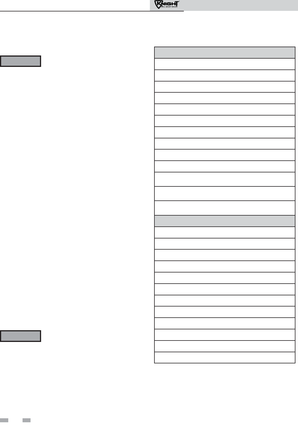
Remove boiler from wood pallet
1. After removing the outer shipping carton from the boiler,
remove the parts box.
2. To remove the boiler from the pallet:
a. Remove the two (2) lag bolts securing the bottom
of the unit to the pallet.
b. Lift the boiler off the wall bracket mounted to
the pallet.
3. Remove the two (2) lag bolts securing the wall bracket to
the wood pallet. Be certain not to lose the wall bracket as
it will be needed for securing the boiler to the wall
(FIG. 2-1).
Do not drop the boiler or bump the jacket
on the floor or pallet. Damage to the
boiler can result.
The gas conversion procedure should be
accomplished BEFORE the boiler is
installed. For a boiler already installed,
you must turn off gas supply, turn off
power, and allow the boiler to cool before
proceeding. You must also completely test
the boiler after conversion to verify
performance as described under Start-up,
Section 10 of this manual.
You must install the propane orifice to fire
the Knight wall mount boiler on propane.
Verify when installing that the orifice size
marking matches boiler size (Table 2A).
Failure to comply could result in severe
personal injury, death, or substantial
property damage.
1. Remove the front access cover from the unit (no tools
required for removal).
2. Disconnect the ribbon cable from the control board.
Remove the four (4) screws securing the bezel to the front of
the unit and remove the bezel.
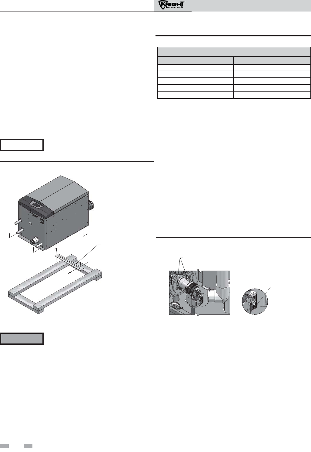
3. Locate the power switch on the gas valve and turn the power
switch to the “OFF” position (FIG. 2-2).
4. Disconnect the Molex plug from the wiring connector
located on the gas valve.
5. Using a 5/16" nut driver, loosen the band clamp securing the
air intake coupler to the gas valve venturi. Remove the air
intake pipe and coupler from the gas valve venturi.
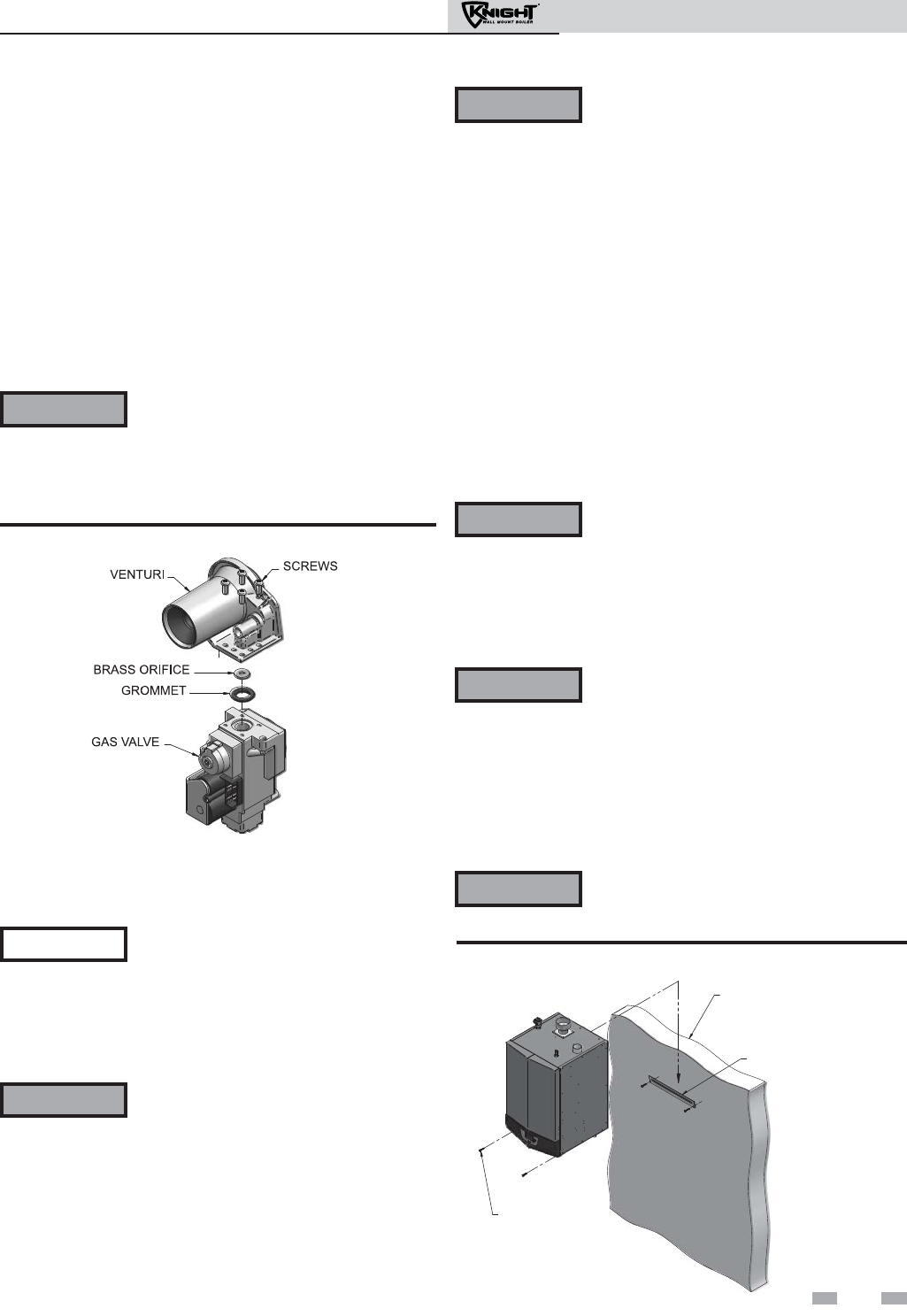
6. Using a 4mm Allen wrench, remove the two (2) screws
securing the gas valve venturi to the inlet of the combustion
blower (FIG. 2-2). Remove the gas valve venturi assembly
from the unit.
DO NOT DISCARD-
WILL BE NEEDED TO
SECURE THE BOILER
TO THE WALL
REMOVE SHIPPING
[WALL] BRACKET
Figure 2-1 Boiler Mounted on Shipping Pallet
Gas conversions
LP Conversion Table
Model LP Orifice Stamping
51 50
81 80
106 105
151 210 / W150
211 210 / W150
NOTICE
WARNING
Table 2A LP Conversion Table
Figure 2-2 Gas Valve Power Switch & Venturi Removal
DETAIL
POWER SWITCH
REMOVE THE TWO (2) SCREWS
SECURING THE GAS VALVE VENTURI
TO THE INLET OF THE COMBUSTION BLOWER
7. Using a 4mm Allen wrench, remove the four (4) screws
securing the gas valve to the venturi (FIG. 2-3).
8. Locate the propane orifice disk from the conversion kit bag.
Verify that the stamping on the orifice disk matches the
boiler size (51 - 211, see Table 2A).
9. Place the orifice into the black rubber grommet in the side of
the gas valve and secure inside the gas valve (see FIG. 2-3).
10. Reposition the gas valve against the venturi and replace the
four (4) screws removed in Step 7, securing the valve to the
venturi (FIG. 2-3).
11. Reposition the gas valve venturi assembly inside the unit.
Secure the gas valve venturi to the combustion blower by
replacing the two (2) screws removed in Step 6 (FIG. 2-2).
12. Reattach the air intake pipe and coupler to the gas valve
venturi. Tighten the band clamp to secure.
Installation & Operation Manual
13
2 Prepare boiler (continued)
FASTENERS
APPROPRIATE
FOR WALL TYPE
QTY: 4
MOUNTING BRACKET
(FACTORY SUPPLIED)
WALL:
WOOD OR METAL STUDS ON
16" CENTERS
-OR-
MASONRY / POURED CONCRETE
Figure 2-4 Mounting the Boiler
Figure 2-3 Installing Propane Orifice
13. Reattach the wiring connector to the gas valve. Tighten
the screw on the wiring connector to secure to the gas
valve.
14. Turn the gas valve power switch to the “ON” position.
15. Reattach the bezel to the unit. Reconnect the ribbon cable
to the control board.
16. After installation is complete, fill out the gas conversion
label (in the conversion kit bag) and affix it to the unit
under the boiler rating plate inside the unit. Attach the LP
caution label (in the conversion kit bag) to the left side of
the unit in the lower left corner.
17. Replace the front access cover.
2. Mount the wall bracket using the 2 1/4" lag bolts
provided. Make sure the top edge of the bracket is away
from the wall. Ensure the bracket is level when mounted.
Extreme care is needed to ensure the bolts are secured in
the center of the studs.
3. Hang the boiler on the bracket and secure the bottom of
the boiler with two (2) additional lag bolts provided.
Mounting to a metal studded wall:
1. The wall mount bracket is designed for a stud spacing of
16 inches from center. For other stud spacing a solid
mounting surface must be provided by the installer.
WARNING The boiler is too heavy for a single person to
lift. A minimum of two people is needed for
mounting the boiler onto the bracket.
2. Mount the wall bracket using two (2) field supplied toggle
bolts capable of supporting 100 pounds each. Ensure the
top edge of the bracket is away from the wall. Ensure the
bracket is level when mounted. Extreme care is needed to
ensure the bolts are secured in the center of the studs.
3. Hang the boiler on the bracket and secure the bottom of the
boiler with two (2) field supplied toggle bolts.
WARNING Do not mount the boiler to a hollow wall. Be
sure to mount the boiler to the studs only.
Mounting the boiler
See page 9 of this manual for boiler mounting location
instructions.
NOTICE The Knight Wall Mount boiler is not
intended for floor installation.
Mounting to a wood studded wall:
1. The wall mount bracket is designed for a stud spacing of
16 inches from center. For other stud spacing a solid
mounting surface must be provided by the installer.
WARNING Do not mount the boiler to a hollow wall.
Be sure to mount the boiler to the studs
only.
Mounting to a concrete wall:
1. Mount the wall bracket using the two (2) wedge anchor
bolts provided with the bracket. To mount the wedge
anchor bolts, drill a 1/4" diameter hole 1 1/8" deep and
insert anchor. Hang the bracket from the anchor and secure
with the two nuts provided. Make sure the top edge of the
bracket is away from the wall. Ensure bracket is level when
mounted. Extreme care is needed to ensure the bolts are
secured in the center of the studs.
Note: If wall thickness does not allow a 1 1/8" deep hole, field
supplied hardware suitable for the application should be
provided.
2. Hang the boiler on the bracket and secure the bottom of the
boiler with two (2) remaining anchors, following the
instructions above.
WARNING The boiler is too heavy for a single person to
lift. A minimum of two people is needed for
mounting the boiler onto the bracket.
WARNING After converting to LP, check combustion
per the Start-up procedure in Section 10
of this manual. Failure to check and
verify combustion could result in severe
personal injury, death, or substantial
property damage.
WARNING The boiler is too heavy for a single person to
lift. A minimum of two people is needed for
mounting the boiler onto the bracket.
3 General venting
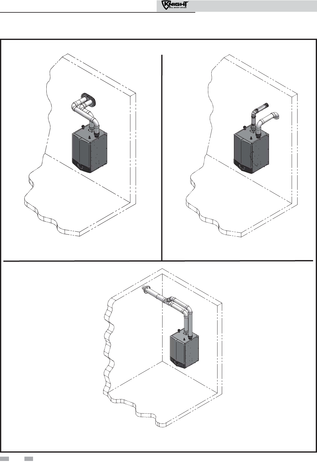
Figure 3-1 PVC/CPVC Two-Pipe Sidewall
Termination - See page 21 for more details
Figure 3-3 PVC/CPVC Concentric Sidewall
Termination - See page 24 for more details
Direct venting options - Sidewall Vent
Figure 3-2 Stainless Steel Two-Pipe Sidewall
Termination - See page 22 for more details
14
Installation & Operation Manual
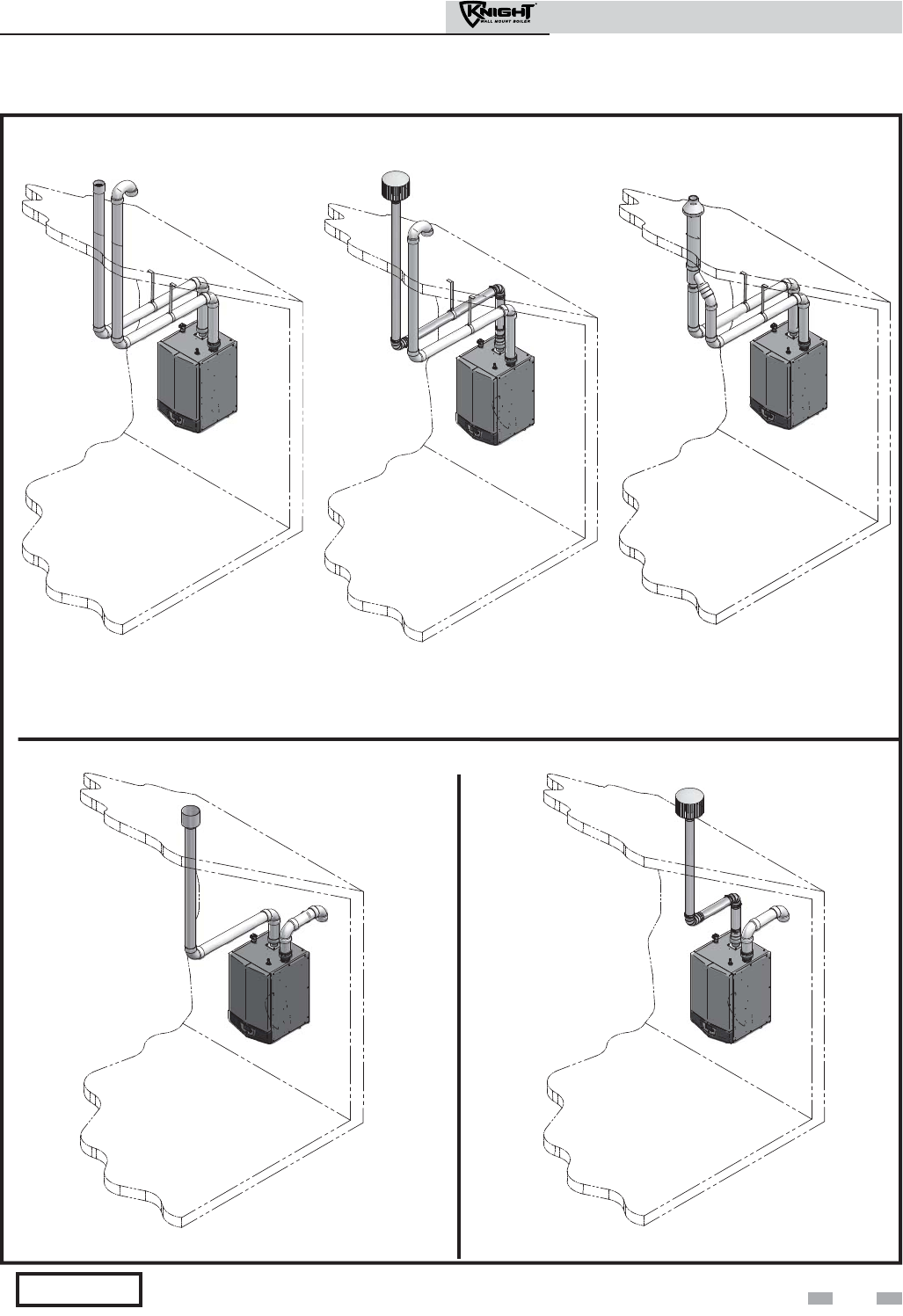
Figure 3-4 PVC/CPVC Two-Pipe
Vertical Termination - See page 27
for more details
Figure 3-5 Stainless Steel Two-Pipe
Vertical Termination - See page 27
for more details
Figure 3-7 PVC/CPVC Vertical Vent, Sidewall Air Figure 3-8 Stainless Steel Vertical Vent, Sidewall Air
Direct venting options - Vertical Vent
Direct venting options - Vertical Vent, Sidewall Air
Stainless steel vent/air design and terminations will vary slightly by manufacturer.
NOTICE
Figure 3-6 PVC/CPVC Concentric
Vertical Termination - See page 29
for more details
15
3 General venting (continued)
Installation & Operation Manual
16
Installation & Operation Manual
3 General venting
PVC/CPVC Vent piping materials
Use only the materials listed in Table 3A for
vent pipe, and fittings. Failure to comply
could result in severe personal injury, death,
or substantial property damage.
Installation must comply with local
requirements and with the National Fuel Gas
Code, ANSI Z223.1 for U.S. installations or
CSA B149.1 for Canadian installations.
Install vent and combustion air piping
DANGER The Knight wall mount boiler must be
vented and supplied with combustion and
ventilation air as described in this section.
Ensure the vent and air piping and the
combustion air supply comply with these
instructions regarding vent system, air
system, and combustion air quality. See also
Section 1 of this manual.
Inspect finished vent and air piping
thoroughly to ensure all are airtight and
comply with the instructions provided and
with all requirements of applicable codes.
Failure to provide a properly installed vent
and air system will cause severe personal
injury or death.
All PVC vent pipes must be glued, properly
supported, and the exhaust must be pitched
a minimum of a 1/4 inch per foot back to the
boiler (to allow drainage of condensate).
WARNING
NOTICE
WARNING
WARNING For closet and alcove installations, CPVC or
stainless steel material MUST BE used in a
closet/alcove structure. Failure to follow this
warning could result in fire, personal injury,
or death.
NOTICE
Requirements for installation in
Canada
1. Installations must be made with a vent pipe system
certified to ULC-S636.
IPEX is an approved vent manufacturer in Canada
supplying vent material listed to ULC-S636.
2. The first three (3) feet of plastic vent pipe from the
appliance flue outlet must be readily accessible for visual
inspection.
3. The components of the certified vent system must not be
interchanged with other vent systems or unlisted
pipe/fittings.
4. The 2" and 3" Concentric Vent Kits available from
Lochinvar (see Section 4 – Sidewall Termination – Optional
Concentric Vent) and the 2" and 3" Concentric Vent Kits
available from IPEX are approved for use on the Knight
wall mount boiler. Both kits are listed to the ULC-S636
standard for use in Canada.
For models 50 - 105 when transitioning
from 2 to 3 inch vent diameter, a 2" pipe
section and 2" to 3" increaser are required
to be CPVC when PVC/CPVC vent is used.
For installations using 2" vent, the first
seven (7) equivalent feet of vent must be
CPVC (field supplied). See examples below.
WARNING
Examples: 1. Seven (7) feet vertical
2. Connector + 90° elbow + 2 feet horizontal
3. One (1) foot vertical + 90° elbow + 1 foot
horizontal
This appliance requires a special venting
system. The vent connection to the
appliance must be made with the starter
CPVC pipe section provided with the
appliance if PVC/CPVC vent is to be used.
For stainless steel venting use an adapter
from Table 3B (page 18) that corresponds
with the intended vent manufacturer to be
used and discard the CPVC starter piece.
The field provided vent fittings must be
cemented to the CPVC pipe section using an
“All Purpose Cement” suitable for PVC and
CPVC pipe. Use only the vent materials,
primer, and cement specified in this manual
to make the vent connections. Failure to
follow this warning could result in fire,
personal injury, or death.
Installing vent and air piping
Improper installation of PVC or CPVC
systems may result in injury or death.
CAUTION
Use only cleaners, primers, and solvents that
are approved for the materials which are
joined together.
NOTICE
1. Work from the boiler to vent or air termination. Do not
exceed the lengths given in this manual for the air or vent
piping.
2. Cut pipe to the required lengths and deburr the inside and
outside of the pipe ends.
3. Chamfer outside of each pipe end to ensure even cement
distribution when joining.
4. Clean all pipe ends and fittings using a clean dry rag.
(Moisture will retard curing and dirt or grease will prevent
adhesion.)
WARNING Insulation should not be used on PVC or
CPVC venting materials. The use of
insulation will cause increased vent wall
temperatures, which could result in vent
pipe failure.
3 General venting (continued)
Table 3A Vent Pipe, and Fittings
5. Dry fit vent or air piping to ensure proper fit up before
assembling any joint. The pipe should go a third to
two-thirds into the fitting to ensure proper sealing after
cement is applied.
6. Priming and Cementing:
a. Handle fittings and pipes carefully to prevent
contamination of surfaces.
b. Apply a liberal even coat of primer to the fitting
socket.
c. Apply a liberal even coat of primer to the pipe end to
approximately 1/2" beyond the socket depth.
d. Apply a second primer coat to the fitting socket.
e. While primer is still wet, apply an even coat of
approved cement to the pipe equal to the depth of
the fitting socket.
f. While primer is still wet, apply an even coat of
approved cement to the fitting socket.
g. Apply a second coat of cement to the pipe.
h. While the cement is still wet, insert the pipe into the
fitting, if possible twist the pipe a 1/4 turn as you insert
it. NOTE: If voids are present, sufficient cement was
not applied and joint could be defective.
i. Wipe excess cement from the joint removing ring or
beads as it will needlessly soften the pipe.
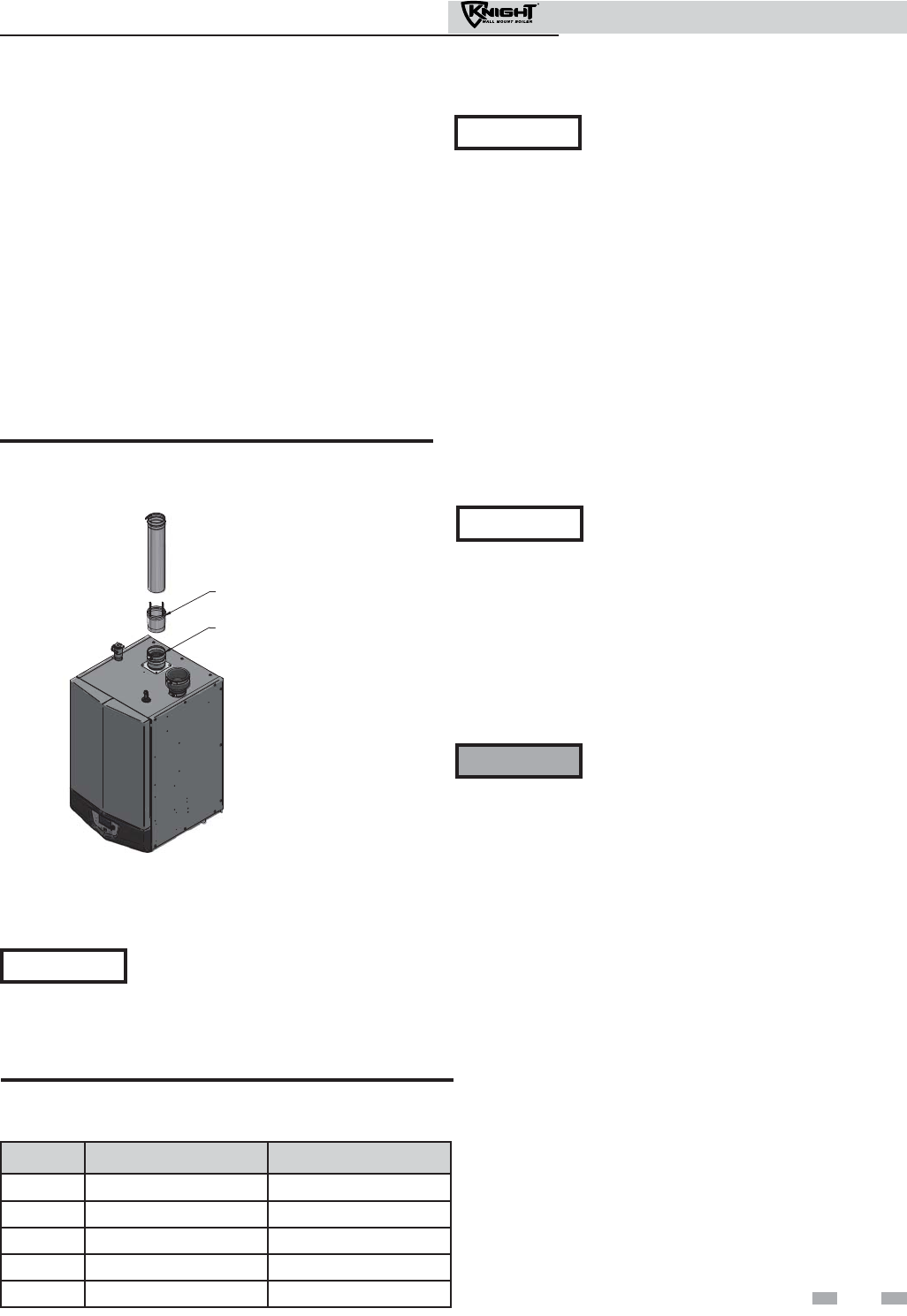
PVC/CPVC air intake/vent connections
1. Combustion Air Intake Connector (FIG. 3-9) - Used to provide combustion air directly to the unit from outdoors. A fitting
is provided on the unit for final connection. Combustion air piping must be supported per guidelines listed in the National
Mechanical Code, Section 305, Table 305.4 or as local codes dictate.
2. Vent Connector (FIG. 3-9) - Used to provide a passageway for conveying combustion gases to the outside. A transition
fitting is provided on the unit for final connection. Vent piping must be supported per the National Building Code, Section
305, Table 305.4 or as local codes dictate.
VENT
AIR
Figure 3-9 Near Boiler PVC/CPVC Venting
Air inlet pipe materials:
The air inlet pipe(s) must be sealed. Choose acceptable
combustion air inlet pipe materials from the following list:
PVC, CPVC or ABS
Dryer Vent or Sealed Flexible Duct (not recommended
for rooftop air inlet)
Galvanized steel vent pipe with joints and seams sealed as
specified in this section.
Type “B” double-wall vent with joints and seams sealed as
specified in this section.
AL29-4C, stainless steel material to be sealed to
specification of its manufacturer.
*Plastic pipe may require an adapter (not provided) to
transition between the air inlet connection on the appliance and
the plastic air inlet pipe.
All vent pipe materials and fittings must comply with the following:
Item Material Standards for installation in:
United States Canada
Vent pipe and fittings
PVC schedule 40 ANSI/ASTM D1785 CPVC and PVC venting must be ULC-
S636 Certified. IPEX is an approved
manufacturer in Canada supplying vent
material listed to ULC-S636.
PVC-DWV ANSI/ASTM D2665
CPVC schedule 40/80 ANSI/ASTM F441
AL29-4C UL1738 ULC-S636
Pipe cement/primer PVC ANSI/ASTM D2564 IPEX System 636
Cements & Primers
CPVC ANSI/ASTM F493
NOTICE: DO NOT USE CELLULAR (FOAM) CORE PIPE
Approved Stainless Steel Vent Manufacturers
Make Model
ProTech Systems (Simpson Dura-Vent Co.) FasNSeal Vent / FasNSeal Flex* Vent
Z-Flex (Nova Flex Group) Z-Vent
Heat Fab (Selkirk Corporation) Saf-T Vent
17
*Use of FasNSeal Flex smooth inner wall vent is to be used in vertical or near vertical sections only, taking precaution to ensure
no sagging occurs of the vent system. Connect to the FasNSeal rigid vent using specially designed adapters and sealing method,
see manufacturer’s instructions.
Installation & Operation Manual
18
Installation & Operation Manual
3 General venting
Sealing of Type “B” double-wall vent material or galvanized
vent pipe material used for air inlet piping on a sidewall or
vertical rooftop Combustion Air Supply System:
a. Seal all joints and seams of the air inlet pipe using either
Aluminum Foil Duct Tape meeting UL Standard 723 or
181A-P or a high quality UL Listed silicone sealant such as
those manufactured by Dow Corning or General Electric.
b. Do not install seams of vent pipe on the bottom of
horizontal runs.
c. Secure all joints with a minimum of three sheet metal
screws or pop rivets. Apply Aluminum Foil Duct Tape or
silicone sealant to all screws or rivets installed in the vent
pipe.
d. Ensure that the air inlet pipes are properly supported.
The PVC, CPVC, or ABS air inlet pipe should be cleaned and
sealed with the pipe manufacturer’s recommended solvents
and standard commercial pipe cement for the material used.
The PVC, CPVC, ABS, Dryer Vent or Flex Duct air inlet pipe
should use a silicone sealant to ensure a proper seal at the
appliance connection and the air inlet cap connection. Dryer
vent or flex duct should use a screw type clamp to seal the vent
to the appliance air inlet and the air inlet cap. Proper sealing
of the air inlet pipe ensures that combustion air will be free of
contaminants and supplied in proper volume.
When a sidewall or vertical rooftop combustion air supply
system is disconnected for any reason, the air inlet pipe must
be resealed to ensure that combustion air will be free of
contaminants and supplied in proper volume.
DANGER Failure to properly seal all joints and seams
as required in the air inlet piping may
result in flue gas recirculation, spillage of
flue products and carbon monoxide
emissions causing severe personal injury
or death.
Stainless steel vent
This product has been approved for use with stainless steel
using the manufacturers listed in Table 3A.
Use only the materials, vent systems, and
terminations listed in Table 3B. DO NOT
mix vent systems of different types or
manufacturers, unless listed in this manual.
Failure to comply could result in severe
personal injury, death, or substantial
property damage.
WARNING
Installations must comply with applicable
national, state, and local codes. Stainless
steel vent systems must be listed as a
UL-1738 approved system for the United
States and a ULC-S636 approved system for
Canada.
NOTICE
Installation of a stainless steel vent system
should adhere to the stainless steel vent
manufacturer’s installation instructions
supplied with the vent system.
NOTICE
The installer must use a specific vent starter
adapter at the flue collar connection,
supplied by the vent manufacturer to adapt
to its vent system. See Table 3B for approved
vent adapters. Discard CPVC starter piece.
NOTICE
Table 3B Approved Stainless Steel Terminations and Adapters
Model
ProTech Heat Fab Z Flex
FasNSeal Saf-T Vent Z-Vent
**Boiler
Adapter
Flue
Termination
Intake
Air
Termination
**Boiler
Adapter
Intermediate
Adapter
Flue
Termination
Intake
Air
Termination
**Boiler
Adapter
Flue
Termination
Intake Air
Termination
51 - 211
300716
(Vent)
300715
(Intake Air)
FSBS3
FSRC3(R.C) 303889
WB50210
(Vent)
KB80210
(Intake Air)
9353BUREZ-1* 9392
5300CI 9314TERM
2SVSLPVC3
(Vent)
2SVSLA03
(Intake Air)
2SVSTP03
2SVSRCX03 2SVSTEX0390
* = This adapter must be used in addition to the boiler adapter for Saf-T vent pipe as shown in FIG. 3-10, unless approved vent
other than standard diameter is used. Consult a Heat Fab representative for questions.
**The stainless steel venting option is only available in 3" vent diameters.
WARNING Using vent or air intake materials other
than those specified, failure to properly
seal all seams and joints or failure to follow
vent pipe manufacturer’s instructions can
result in personal injury, death or property
damage. Mixing of venting materials will
void the warranty and certification of the
appliance.
NOTICE The use of double-wall vent or insulated
material for the combustion air inlet pipe
is recommended in cold climates to
prevent the condensation of airborne
moisture in the incoming combustion air.
3 General venting (continued)
Removing from existing vent
Follow the instructions in Section 1, page 11 of this manual
when removing a boiler from an existing vent system.
Vent and air piping
Vent and air system:
Installation must comply with local
requirements and with the National Fuel Gas
Code, ANSI Z223.1 for U.S. installations or
CSA B149.1 for Canadian installations.
You must also install air piping from outside to the boiler air
intake adapter. The resultant installation is direct vent (sealed
combustion).
You may use any of the vent/air piping methods covered in this
manual. Do not attempt to install the Knight wall mount boiler
using any other means.
NOTICE
WARNING
VENT
3" S.S. INTERMEDIATE
(FOR SAF-T VENT ONLY)
3" S.S. ADAPTER
Figure 3-10 Near Boiler Stainless Steel Venting
Stainless steel air intake/vent
connections
1. Combustion Air Intake Connector (FIG. 3-10) - Used
to provide combustion air directly to the unit from
outdoors. A fitting is provided on the unit for final
connection. Combustion air piping must be supported
per guidelines listed in the National Mechanical Code,
Section 305, Table 305.4 or as local codes dictate.
2. Vent Connector (FIG. 3-10) - Used to provide a
passageway for conveying combustion gases to the
outside. A transition fitting is provided on the unit for
final connection. Vent piping must be supported per the
National Building Code, Section 305, Table 305.4 or as
local codes dictate.
Maximum allowable combustion air and
vent piping lengths are as follows:
Model 2" Max Vent/Air 3" Max Vent/Air
51 40 feet 100 feet
81 40 feet 100 feet
106 40 feet 100 feet
151 N/A 100 feet
211 N/A 100 feet
Increasing or decreasing the size of the
combustion air or vent piping beyond the
sizes listed in Table 3C is not authorized.
NOTICE
When determining equivalent combustion air and vent length,
add 5 feet for each 90° elbow, 3 feet for each 45° elbow, and 3 feet
for the concentric vent kit, see example below.
EXAMPLE: 20 feet of PVC pipe + (4) 90° elbows + (2) 45°
elbows + (1) concentric vent kit = 49 equivalent feet of piping.
Table 3C Maximum Combustion Air and Vent Piping
Lengths
Note: The minimum combustion air and vent piping length is
12 equivalent feet.
For 2" vent / air lengths greater than 40 feet,
consult the factory.
NOTICE
The Knight wall mount boiler uses model specific
combustion air intake and vent piping sizes as detailed in
Table 3C below.
Vent, air piping and termination:
The Knight wall mount boiler vent and air piping can be
installed through the roof or through a sidewall. Follow the
procedures in this manual for the method chosen. Refer to the
information in this manual to determine acceptable vent and air
piping length.
DO NOT mix components from different
systems. The vent system could fail, causing
leakage of flue products into the living space.
Use only approved stainless steel, PVC or
CPVC pipe and fittings. For PVC/CPVC use
with primer and cement specifically
designed for the material used.
19
Installation & Operation Manual
Air contamination
Pool and laundry products and common household and
hobby products often contain fluorine or chlorine
compounds. When these chemicals pass through the boiler,
they can form strong acids. The acid can eat through the
boiler wall, causing serious damage and presenting a possible
threat of flue gas spillage or boiler water leakage into the
building.
If the boiler combustion air inlet is located
in a laundry room or pool facility, for
example, these areas will always contain
hazardous contaminants.
To prevent the potential of severe personal
injury or death, check for areas and
products listed in Table 1A, page 10 before
installing the boiler or air inlet piping.
If contaminants are found, you MUST:
• Remove contaminants permanently.
—OR—
• Relocate air inlet and vent
terminations to other areas.
WARNING
WARNING
Optional room air
Commercial applications utilizing the Knight wall mount
boiler may be installed with a single pipe carrying the flue
products to the outside while using combustion air from the
equipment room. In order to use the room air venting option
the following conditions and considerations must be
followed.
• The unit MUST be installed with the appropriate
room air kit (Table 3D).
• The equipment room MUST be provided with
properly sized openings to assure adequate
combustion air. Please refer to instructions provided
with the room air kit.
• There will be a noticeable increase in the noise level
during normal operation from the inlet air opening.
• Using the room air kit makes the unit vulnerable to
combustion air contamination from within the
building. Please review Section 1, Prevent
Combustion Air Contamination, to ensure proper
installation.
• Vent system and terminations must comply with the
standard venting instructions set forth in this
manual.
WARNING When utilizing the single pipe method,
provisions for combustion and ventilation
air must be in accordance with Air for
Combustion and Ventilation, of the latest
edition of the National Fuel Gas Code,
ANSI Z223.1, in Canada, the latest edition
of CGA Standard B149 Installation Code
for Gas Burning Appliances and
Equipment, or applicable provisions of the
local building codes.
Model Kit Number
51 - 211 KIT30051
Table 3D Optional Room Air Kit
NOTICE Optional room air is intended for
commercial applications. Combustion air
piping to the outside is recommended for
residential applications.
Please read the information given in Table 1A, page 10, listing
contaminants and areas likely to contain them. If
contaminating chemicals will be present near the location of the
boiler combustion air inlet, have your installer pipe the boiler
combustion air and vent to another location, per this manual.
20
3 General venting
Installation & Operation Manual
4 Sidewall direct venting
Vent/air termination – sidewall
Follow instructions below when
determining vent location to avoid
possibility of severe personal injury, death,
or substantial property damage.
A gas vent extending through an exterior
wall shall not terminate adjacent to a wall
or below building extensions such as eaves,
parapets, balconies, or decks. Failure to
comply could result in severe personal
injury, death, or substantial property
damage.
Installation must comply with local
requirements and with the National Fuel
Gas Code, ANSI Z223.1 for U.S.
installations or CSA B149.1 for Canadian
installations.
WARNING
WARNING
NOTICE
WARNING Do not connect any other appliance to the
vent pipe or multiple boilers to a common
vent pipe. Failure to comply could result in
severe personal injury, death, or substantial
property damage.
Determine location
Locate the vent/air terminations using the following
guidelines:
1. The total length of piping for vent or air must not exceed
the limits given in the General Venting Section on page 19
of this manual.
2. You must consider the surroundings when terminating
the vent and air:
a. Position the vent termination where vapors will
not damage nearby shrubs, plants or air
conditioning equipment or be objectionable.
b. The flue products will form a noticeable plume as
they condense in cold air. Avoid areas where the
plume could obstruct window views.
c. Prevailing winds could cause freezing of
condensate and water/ice buildup where flue
products impinge on building surfaces or plants.
d. Avoid possibility of accidental contact of flue
products with people or pets.
e. Do not locate the terminations where wind eddies
could affect performance or cause recirculation,
such as inside building corners, near adjacent
buildings or surfaces, window wells, stairwells,
alcoves, courtyards, or other recessed areas.
TO BOILER
INTAKE AIR
CONNECTION
FROM BOILER
VENT PIPE
CONNECTION
TERMINATION
PLATE
BIRD SCREEN
GRADE OR
SNOW LINE
12”
MIN
BIRD SCREEN
12” MIN
15” MAX
Do not exceed the maximum lengths of the
outside vent piping shown in FIG. 4-1B.
Excessive length exposed to the outside
could cause freezing of condensate in the
vent pipe, resulting in potential boiler
shutdown.
Figure 4-1B Alternate PVC/CPVC Sidewall Termination
of Air and Vent w/Field Supplied Fittings
WARNING
If using the alternate sidewall termination:
3. The air piping must terminate in a down-turned elbow as
shown in FIG. 4-1B. This arrangement avoids recirculation
of flue products into the combustion air stream.
4. The vent piping must terminate in an elbow pointed
outward or away from the air inlet, as shown in FIG. 4-1B.
TO BOILER
INTAKE AIR
CONNECTION
FROM BOILER
VENT PIPE
CONNECTION
VENT / AIR
TERMINATION
GRADE OR
SNOW LINE
12"
MIN
12"
MIN
TO
OVER-
HANG
POSSIBLE ORIENTATIONS
Figure 4-1A PVC/CPVC Sidewall Termination of Air and
Vent
Model Kit Number Vent Size
51 - 106 KIT30044 2 inch vent
151 - 211 KIT30045 3 inch vent
Table 4A Sidewall Vent Kit
21
Installation & Operation Manual
4 Sidewall direct venting
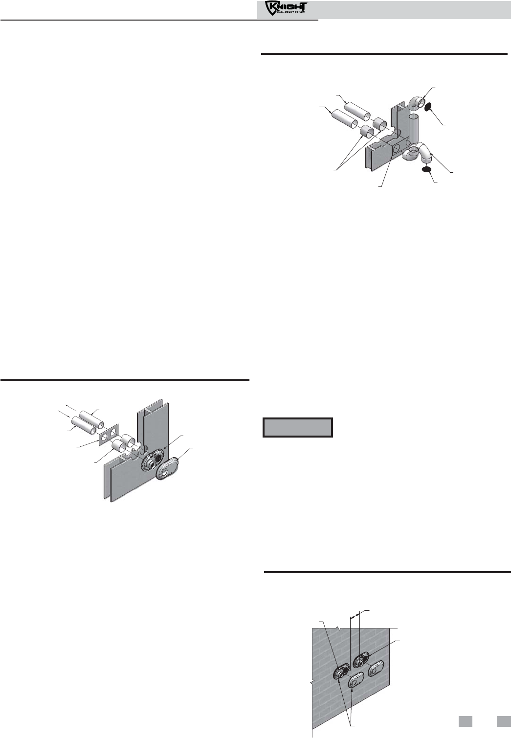
5. Maintain clearances as shown in FIG.’s 4-1A thru 4-3B,
pages 21 and 22. Also maintain the following:
a. Vent must terminate:
• At least 6 feet from adjacent walls.
• No closer than 12 inches below roof overhang.
• At least 7 feet above any public walkway.
• At least 3 feet above any forced air intake within
10 feet.
• No closer than 12 inches below or horizontally
from any door or window or any other gravity air
inlet.
b. Air inlet must terminate at least 12 inches above
grade or snow line; at least 12 inches below the vent
termination (FIG. 4-1B); and the vent pipe must not
extend more than 24 inches vertically outside the
building.
c. Do not terminate closer than 4 feet horizontally
from any electric meter, gas meter, regulator, relief
valve, or other equipment. Never terminate above or
below any of these within 4 feet horizontally.
6. Locate terminations so they are not likely to be damaged by
foreign objects, such as stones or balls, or subject to buildup
of leaves or sediment.
Vent/air termination – sidewall
ALTERNATE VENTING ARRANGEMENT
(IF SPACE PERMITS)
BIRD
SCREEN
12”
MIN
12” MIN
15” MAX
COUPLING
TO BOILER
INTAKE AIR
CONNECTION
FROM BOILER
VENT PIPE
CONNECTION
BIRD SCREEN
GRADE OR
SNOW LINE
Figure 4-1C Alternate Venting Arrangement (if Space
Allows) w/Field Supplied Fittings
VENT / AIR
TERMINATION
12"
MIN.
12"
MIN.
12"
MIN.
Figure 4-2A Clearance to Gravity Air Inlets
12”
MIN
BIRD
SCREEN
(TYPICAL)
12”
MIN
12”
MIN
Figure 4-2B Alternate Clearance to Gravity Air Inlets
w/Field Supplied Fittings
FORCED AIR
INLET
VENT / AIR
TERMINATION
7' MIN. ABOVE ANY
PUBLIC WALKWAY
IF LESS
THAN 10’
36"
MIN.
IF LESS
THAN 10’
36”
MIN
FORCED AIR
INLET
BIRD
SCREEN
(TYPICAL)
7’ MIN ABOVE ANY
PUBLIC WALKWAY
Figure 4-3B Alternate Clearance to Forced Air Inlets
w/Field Supplied Fittings
TO BOILER
INTAKE AIR
CONNECTION
FROM
BOILER
VENT PIPE
CONNECTION
BIRD SCREEN
12" MIN
12" MIN
15" MAX
GRADE OR SNOW LINE
Figure 4-1D Alternate Venting Arrangement - Typical
Stainless Steel Sidewall Termination of Air and Vent
w/Field Supplied Fittings
Figure 4-3A Clearance to Forced Air Inlets
22
Installation & Operation Manual
4 Sidewall direct venting (continued)
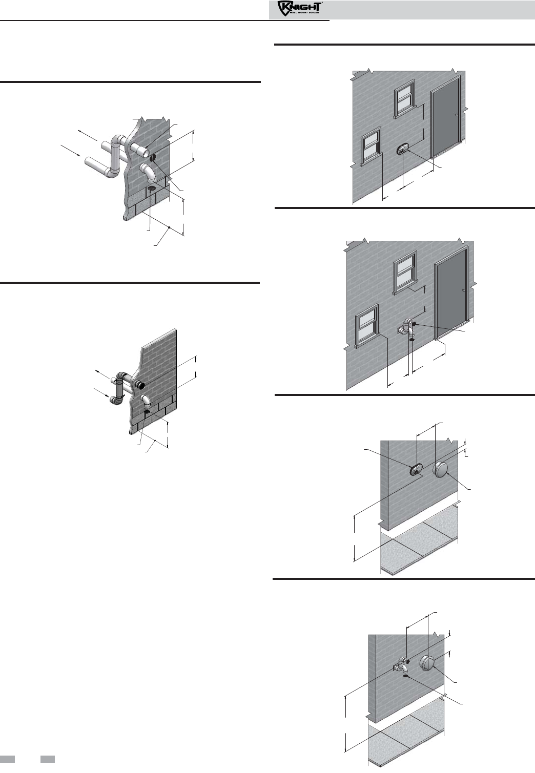
Termination and fittings
1. The air termination coupling must be oriented at least
12 inches above grade or snow line as shown in FIG. 4-1A,
page 21.
2. Maintain the required dimensions of the finished
termination piping as shown in FIG. 4-1A, page 21.
3. If using the alternate sidewall termination do not extend
exposed vent pipe outside of building more than shown in
this document. Condensate could freeze and block vent
pipe.
4. PVC/CPVC terminations are designed to accommodate any
wall thickness of standard constructions per the directions
found in this manual.
Prepare wall penetrations (Alternate -
Field Supplied Option)
1. Air pipe penetration:
a. Cut a hole for the air pipe. Size the air pipe hole as
close as desired to the air pipe outside diameter.
2. Vent pipe penetration:
a. Cut a hole for the vent pipe. For either combustible
or noncombustible construction, size the vent pipe
hole with at least a 1/2 inch clearance around the vent
pipe outer diameter:
• 3½ inch hole for 2 inch vent pipe
• 4½ inch hole for 3 inch vent pipe
b. Insert a galvanized metal thimble in the vent pipe
hole as shown in FIG. 4-4B.
3. Use a sidewall termination plate as a template for correct
location of hole centers.
4. Follow all local codes for isolation of vent pipe when
passing through floors or walls.
5. Seal exterior openings thoroughly with exterior caulk.
VENT PIPING
GALVANIZED
THIMBLE
VENT CAP
AIR PIPING
WALL PLATE
VENT PLATE
Figure 4-4A Sidewall Termination Assembly
ELBOW
BIRD SCREEN
ELBOW
BIRD SCREEN
SIDEWALL
TERMINATION PLATE
GALVANIZED
THIMBLE
VENT PIPING
AIR PIPING
Figure 4-4B Alternate Sidewall Termination Assembly
w/Field Supplied Fittings
All vent pipes and air inlets must terminate
at the same height to avoid possibility of
severe personal injury, death, or substantial
property damage.
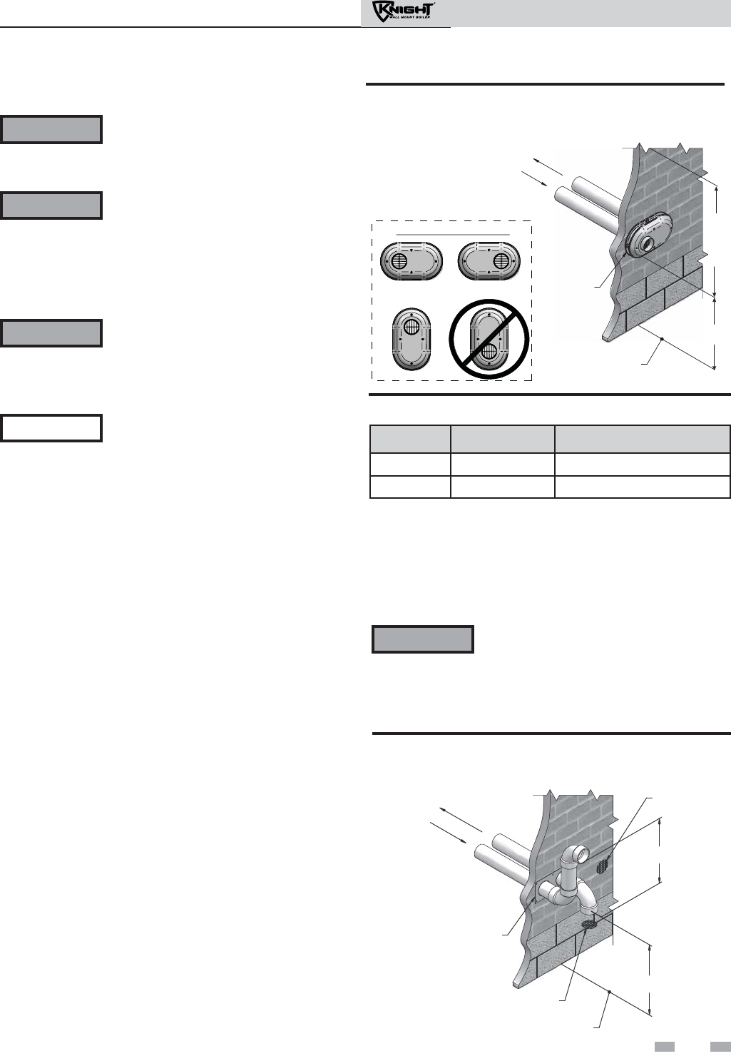
Multiple vent/air terminations
1. When terminating multiple Knight wall mount boilers
terminate each vent/air connection as described in this
manual (FIG. 4-5A).
2. Place wall penetrations to obtain minimum clearance of 12
inches between edge of air inlet and adjacent vent outlet, as
shown in FIG. 4-5A for U.S. installations. For Canadian
installations, provide clearances required by CSA B149.1
Installation Code.
3. The air inlet of a Knight wall mount boiler is part of a direct
vent connection. It is not classified as a forced air intake
with regard to spacing from adjacent boiler vents.
WARNING
12" MIN. BETWEEN EDGE OF AIR
INLET AND ADJACENT VENT OUTLET
VENT / AIR
TERMINATION
VENT
AIR
Figure 4-5A Multiple Vent Terminations (must also
comply with Figure 4-1A)
Prepare wall penetrations
1. Use the factory supplied wall plate as a template to locate
the vent and air intake holes and mounting holes.
Air pipe penetration:
a. Cut a hole for the air pipe. Size the air pipe hole as
close as desired to the air pipe outside diameter.
Vent pipe penetration:
a. Cut a hole for the vent pipe. For either
combustible or noncombustible construction, size
the vent pipe hole with at least a 1/2 inch clearance
around the vent pipe outer diameter:
• 3½ inch hole for 2 inch vent pipe
• 4½ inch hole for 3 inch vent pipe
Drill 3/16" diameter holes for inserting the plastic anchors
into the wall.
2. Install the vent and air intake piping through the wall into
the vent plate openings. Seal all gaps between the pipes and
wall. Use RTV silicone sealant to seal the air pipe. Use the
cement/primer listed in Table 3A on page 17 to seal the vent
pipe.
3. Mount and secure the vent plate to the wall using stainless
steel screws. Seal around the plate to the wall assuring no
air gaps.
4. Assemble the vent cap to the vent plate (see FIG. 4-4A).
Insert the stainless steel screws into the vent cap screw hole
openings and securely attach the vent cap to the vent plate.
5. Seal all wall cavities.
23
Installation & Operation Manual
4 Sidewall direct venting
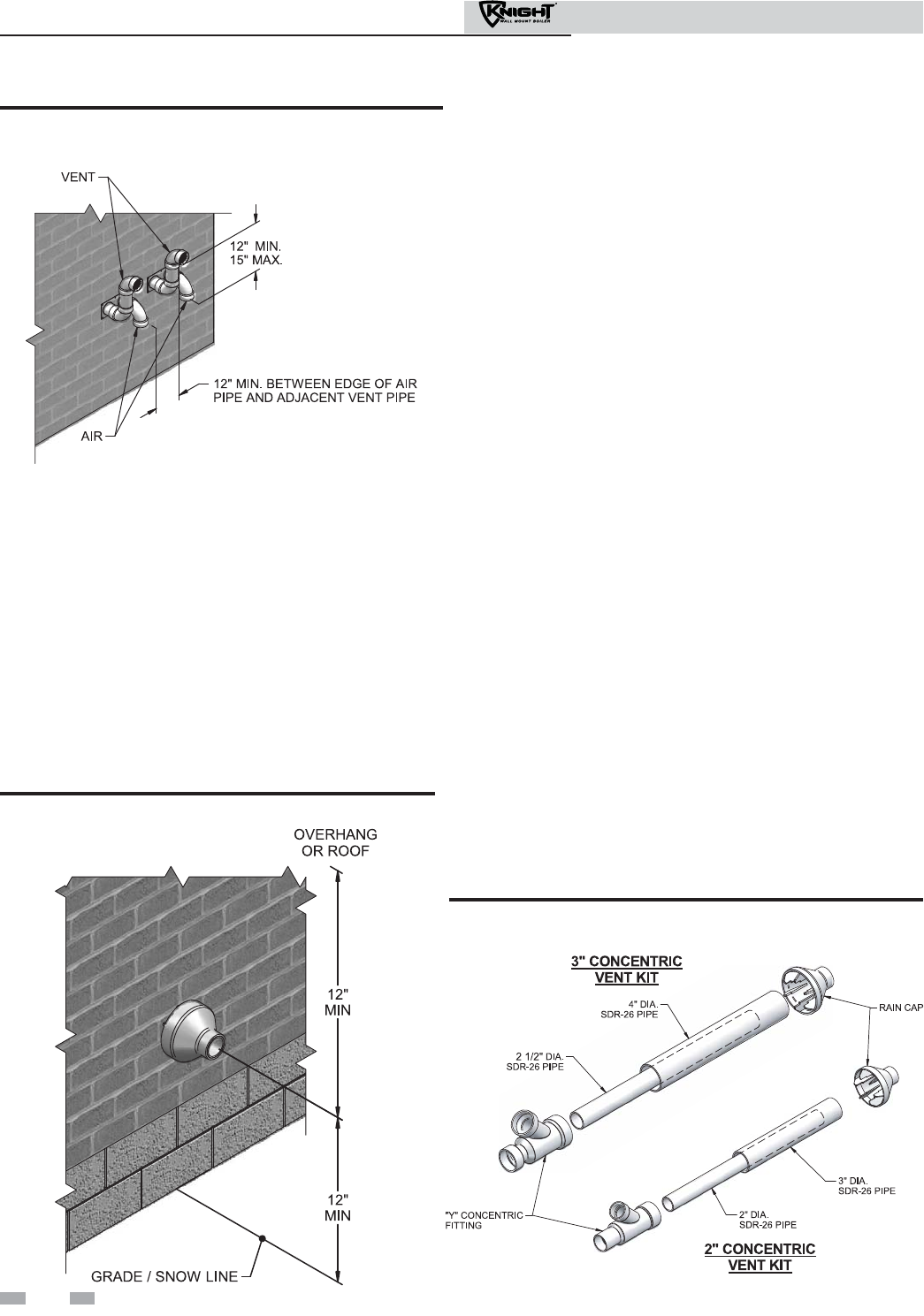
Sidewall termination – optional
concentric vent
Description and usage
Lochinvar offers optional concentric combustion air and vent
pipe termination kits (Factory Kit #CVK3003 - 3" or
#CVK3008 - 2"). Both combustion air and vent pipes must
attach to the termination kit. The termination kit must
terminate outside the structure and must be installed as shown
below in FIG. 4-6.
The required combustion vent pipe and fittings are listed in
Table 3A, on page 17 of this manual.
Figure 4-7 Kit Contents
Sidewall termination installation
1. Determine the best location for the termination kit (see
FIG. 4-6).
2. The total length of piping for vent or air must not exceed the
limits given in the General Venting Section on page 19 of
this manual.
3. You must consider the surroundings when terminating
the vent and air:
a. Position the vent termination where vapors will not
damage nearby shrubs, plants or air conditioning
equipment or be objectionable.
b. The flue products will form a noticeable plume as
they condense in cold air. Avoid areas where the
plume could obstruct window views.
c. Prevailing winds could cause freezing of condensate
and water/ice buildup where flue products impinge
on building surfaces or plants.
d. Avoid possibility of accidental contact of flue
products with people or pets.
f. Do not terminate above any door or window.
Condensate can freeze, causing ice formations.
g. Locate or guard vent to prevent condensate damage
to exterior finishes.
4. Cut one (1) hole (5 inch diameter for #CVK3003
installations or 4 inch diameter for #CVK3008 installations)
into the structure to install the termination kit.
5. Partially assemble the concentric vent termination kit.
Clean and cement using the procedures found in these
instructions.
a. Cement the Y concentric fitting to the larger kit pipe
(FIG. 4-7).
b. Cement the rain cap to the smaller diameter kit pipe
(FIG. 4-7).
Figure 4-6 Concentric Sidewall Termination
Figure 4-5B Alternate Multiple Vent Terminations w/Field
Supplied Fittings (must also comply with Figure 4-1B)
24
Installation & Operation Manual
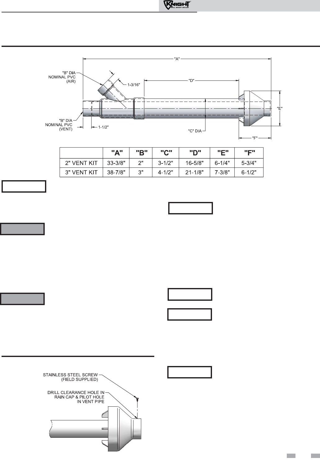
4 Sidewall direct venting (continued)
Sidewall termination – optional concentric vent models
Figure 4-8 Concentric Vent Dimensional Drawing
Instead of cementing the smaller pipe to the
rain cap, a field-supplied stainless steel screw
may be used to secure the two (2)
components together when field disassembly
is desired for cleaning (see FIG. 4-9).
When using the alternate screw assembly
method, drill a clearance hole in the rain cap
and a pilot hole in the vent pipe for the screw
size being used. Failure to drill adequate
holes may cause cracking of PVC
components, allowing combustion products
to be recirculated. Failure to follow this
warning could result in personal injury or
death.
Do not operate the appliance with the rain
cap removed or recirculation of combustion
products may occur. Water may also collect
inside the larger combustion air pipe and
flow to the burner enclosure. Failure to
follow this warning could result in product
damage or improper operation, personal
injury, or death.
Figure 4-9 Rain Cap to Vent Pipe Alternate Assembly
6. Install the Y concentric fitting and pipe assembly through
the structure’s hole.
Do not allow insulation or other materials
to accumulate inside the pipe assembly
when installing through the hole.
7. Install the rain cap and small diameter pipe assembly into
the Y concentric fitting and large pipe assembly. Ensure
small diameter pipe is bottomed and cemented in the Y
concentric fitting.
8. Secure the assembly to the structure as shown in
FIG. 4-10 using field-supplied metal strapping or
equivalent support material.
Ensure termination location clearance
dimensions are as shown in FIG. 4-6.
If assembly needs to be extended to allow
sidewall thickness requirement, the two
(2) pipes supplied in the kit may be
replaced by using the same diameter, field-
supplied SDR-26 PVC (D2241) pipe. Do
not extend dimension D more than 60
inches (see FIG. 4-8).
NOTICE
WARNING
WARNING
NOTICE
NOTICE
NOTICE
If assembly needs to be reduced,
dimension D can be as short as possible.
NOTICE
25
Installation & Operation Manual
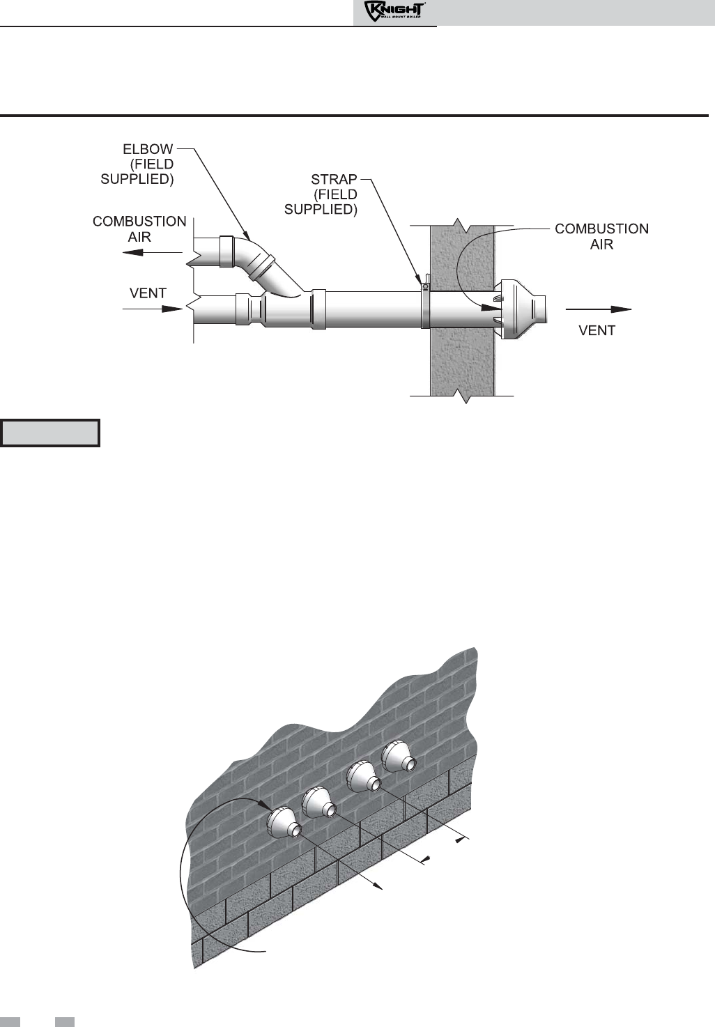
26
Installation & Operation Manual
4 Sidewall direct venting
Sidewall termination – optional concentric vent
Multiventing sidewall terminations
When two (2) or more direct vent appliances are vented near
each other, each appliance must be individually vented (see FIG.
4-11). NEVER common vent or breach vent this appliance.
When two (2) or more direct vent appliances are vented near
each other, two (2) vent terminations may be installed as shown
in FIG. 4-11. It is important that vent terminations be made as
shown to avoid recirculation of flue gases.
VENT
COMBUSTION
AIR
12"
MINIMUM
Figure 4-11 Concentric Vent and Combustion Air Termination
Figure 4-10 Concentric Vent Sidewall Attachment
DO NOT use field-supplied couplings to
extend pipes. Airflow restriction will
occur and may cause intermittent
operation.
9. Cement appliance combustion air and vent pipes to the
concentric vent termination assembly. See FIG. 4-10 for
proper pipe attachment.
10. Operate the appliance one (1) heat cycle to ensure
combustion air and vent pipes are properly connected to
the concentric vent termination connections.
CAUTION
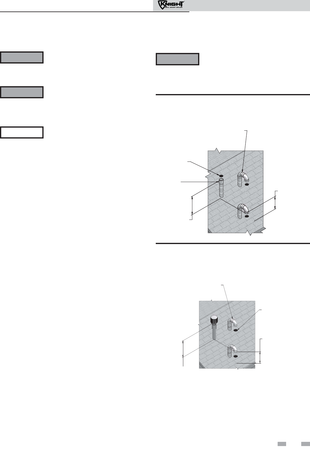
5 Vertical direct venting
Vent/air termination – vertical
Follow instructions below when
determining vent location to avoid
possibility of severe personal injury,
death or substantial property damage.
Installation must comply with local
requirements and with the National Fuel
Gas Code, ANSI Z223.1 for U.S.
installations or CSA B149.1 for
Canadian installations.
Determine location
Locate the vent/air terminations using the following
guidelines:
1. The total length of piping for vent or air must not
exceed the limits given in the General Venting section on
page 19 of this manual.
2. The vent must terminate at least 3 feet above the
highest place in which the vent penetrates the roof and
at least 2 feet above any part of a building within
10 horizontal feet.
3. The air piping must terminate in a down-turned 180°
return pipe no further than 2 feet from the center of the
vent pipe. This placement avoids recirculation of flue
products into the combustion air stream.
4. The vent piping must terminate in an up-turned
coupling as shown in FIG. 5-1A. The top of the
coupling must be at least 1 foot above the air intake.
When the vent termination uses a rain cap as illustrated
in FIG. 5-1B maintain at least 36" (914 mm) above the
air inlet. The air inlet pipe and vent pipe can be located
in any desired position on the roof, but must always be
no further than 2 feet (.6 m) apart and with the vent
termination at least 1 foot above the air intake.
ALTERNATE INTAKE LOCATIONS:
INTAKE PIPES MAY BE LOCATED
ANYWHERE WITHIN 24” OF VENT
PIPE
BIRD SCREEN
(TYPICAL)
COUPLING
(FIELD SUPPLIED)
VENT OUTLET
12” MINIMUM
ABOVE AIR INLET
6” MINIMUM
ABOVE ROOF /
SNOW LINE
VENT
COMBUSTION
AIR
Figure 5-1A PVC/CPVC Vertical Termination of Air and
Vent
5. Locate terminations so they are not likely to be damaged by
foreign objects, such as stones or balls, or subject to buildup
of leaves or sediment.
WARNING
NOTICE
WARNING Do not connect any other appliance to
the vent pipe or multiple boilers to a
common vent pipe. Failure to comply
could result in severe personal injury,
death, or substantial property damage.
WARNING Rooftop vent and air inlet terminations
must terminate in the same pressure zone,
unless vertical vent sidewall air is set up as
shown in the General Venting - Vertical
Vent, Sidewall Air Section.
6" (152 MM) MINIMUM
ABOVE ROOF /
SNOW LINE
VENT
COM,BUSTION
AIR
ALTERNATE INTAKE LOCATIONS:
INTAKE PIPES MAY BE LOCATED
ANYWHERE WITHIN 24” (610 MM)
OF VENT PIPE
VENT OUTLET
36” (914 MM) MINIMUM
ABOVE AIR INLET
BIRD SCREEN
(TYPICAL)
Figure 5-1B Stainless Steel Vertical Termination of Air
and Vent
27
Installation & Operation Manual
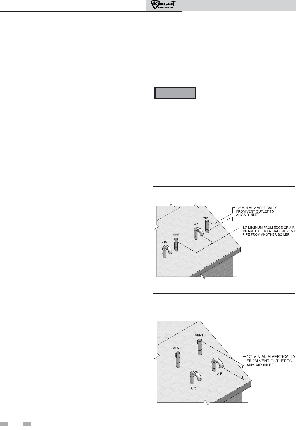
5 Vertical direct venting
Vent/air termination – vertical
Prepare roof penetrations
1. Air pipe penetration:
a. Cut a hole for the air pipe. Size the air pipe hole as
close as desired to the air pipe outside diameter.
2. Vent pipe penetration:
a. Cut a hole for the vent pipe. For either combustible
or noncombustible construction, size the vent pipe
hole with at least a 1/2 inch clearance around the
vent pipe outer diameter:
• 3½ inch hole for 2 inch vent pipe
• 4½ inch hole for 3 inch vent pipe
b. Insert a galvanized metal thimble in the vent pipe
hole.
3. Space the air and vent holes to provide the minimum
spacing shown in FIG. 5-1A, page 27.
4. Follow all local codes for isolation of vent pipe when
passing through floors, ceilings, and roofs.
5. Provide flashing and sealing boots sized for the vent pipe
and air pipe.
Termination and fittings
1. Prepare the vent termination coupling and the air
termination elbow (FIG. 5-1A) by inserting bird screens.
Bird screens should be obtained locally.
2. The air piping must terminate in a down-turned 180°
return bend as shown in FIG. 5-1A. Locate the air inlet
pipe no further than 2 feet from the center of the vent
pipe. This placement avoids recirculation of flue
products into the combustion air stream.
3. The vent piping must terminate in an up-turned coupling
as shown in FIG. 5-1A. The top of the coupling must be
at least 1 foot above the air intake. When the vent
termination uses a rain cap as illustrated in FIG. 5-1B
maintain at least 36" (914 mm) above the air inlet. The
air inlet pipe and vent pipe can be located in any desired
position on the roof, but must always be no further than
2 feet apart and with the vent termination at least 1 foot
above the air intake.
4. Maintain the required dimensions of the finished
termination piping as shown in FIG. 5-1A.
5. Do not extend exposed vent pipe outside of building
more than shown in this document. Condensate could
freeze and block vent pipe.
Multiple vent/air terminations
1. When terminating multiple Knight wall mount boilers,
terminate each vent/air connection as described in this
manual (FIG. 5-2).
Terminate all vent pipes at the same height
and all air pipes at the same height to
avoid possibility of severe personal injury,
death, or substantial property damage.
2. Place roof penetrations to obtain minimum clearance of
12 inches between edge of air intake elbow and adjacent
vent pipe of another boiler for U.S. installations (see
FIG. 5-2). For Canadian installations, provide clearances
required by CSA B149.1 Installation Code.
3. The air inlet of a Knight wall mount boiler is part of a
direct vent connection. It is not classified as a forced air
intake with regard to spacing from adjacent boiler vents.
Figure 5-2 Vertical Terminations with Multiple Boilers
Figure 5-3 Alternate Vertical Terminations with Multiple
Boilers
WARNING
28
Installation & Operation Manual

5 Vertical direct venting (continued)
Vertical termination – optional concentric vent
Description and usage
Lochinvar offers an optional concentric combustion air and
vent pipe termination kit. Both combustion air and vent
pipes must attach to the termination kit. The termination
kit must terminate outside the structure and must be
installed as shown in FIG. 5-4.
Field supplied pipe and fittings are required to complete the
installation.
The required combustion air and vent pipe fittings are
listed in Table 3A, on page 17 of this manual.
Vertical termination installation
1. See Section 5, Vertical Direct Venting - Determine
Location (where applicable).
Instead of cementing the smaller pipe to the
rain cap, a field supplied stainless steel screw
may be used to secure the two (2)
components together when field disassembly
is desired for cleaning (see FIG. 4-9, page 25).
When using the alternate screw assembly
method, drill a clearance hole in the rain cap
and a pilot hole in the vent pipe for the screw
size being used. Failure to drill adequate
holes may cause cracking of PVC
components, allowing combustion products
to be recirculated. Failure to follow this
warning could result in personal injury or
death.
2. Cut one (1) hole (5 inch diameter for #CVK3003
installations or 4 inch diameter for #CVK3008 installations)
into the structure to install the termination kit.
3. Partially assemble the concentric vent termination kit.
Clean and cement following the cleaning procedures in
these instructions.
a. Cement the Y concentric fitting to the larger
diameter kit pipe (see FIG. 4-7, page 24).
b. Cement rain cap to the smaller diameter kit pipe (see
FIG. 4-7, page 24).
Figure 5-4 Concentric Vertical Termination
NOTICE
WARNING
Figure 5-5 Do Not Install U-Bend to Rain Cap
29
Installation & Operation Manual
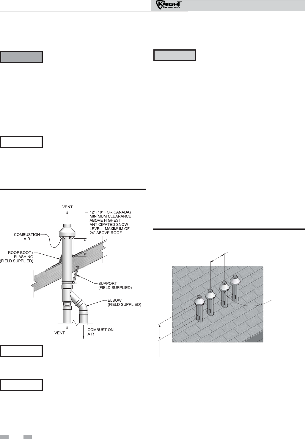
30
Installation & Operation Manual
5 Vertical direct venting
Vertical termination – optional concentric vent
Figure 5-6 Concentric Vent Roof Installation
Ensure termination height is above the
roof surface or anticipated snow level (12
inches in U.S.A. or 18 inches in Canada) as
shown in FIG. 5-4, page 29.
If assembly is too short to meet height
requirement, the two (2) pipes supplied in
the kit may be replaced by using the same
diameter, field supplied SDR-26 PVC
(D2241) pipe. Do not extend dimension D
more than 60 inches (see FIG. 4-8, page 25).
CAUTION DO NOT use field-supplied couplings to
extend pipes. Airflow restriction will occur.
6. Install the rain cap and the small diameter pipe assembly
into the roof penetration assembly. Ensure the small
diameter pipe is cemented and bottomed in the Y
concentric fitting.
7. Cement the appliance combustion air and vent pipes to the
concentric vent termination assembly. See FIG. 5-6 for
proper pipe attachment.
8. Operate the appliance through one (1) heat cycle to ensure
combustion air and vent pipes are properly connected to
the concentric vent termination connections.
Multiventing vertical terminations
When two (2) or more direct vent appliances are vented near
each other, each appliance must be individually vented (see
FIG. 5-7). NEVER common vent or breach vent this appliance.
When two (2) or more direct vent appliances are vented near
each other, two (2) vent terminations may be installed as shown
in FIG. 5-7. It is important that vent terminations be made as
shown to avoid recirculation of flue gases.
12”
MINIMUM
12” (18” FOR CANADA)
MINIMUM CLEARANCE
ABOVE HIGHEST
ANTICIPATED SNOW
LEVEL. MAXIMUM OF
24” ABOVE ROOF.
COMBUSTION
AIR (TYPICAL)
Figure 5-7 Concentric Vent and Combustion Air Vertical
Termination
Do not operate the appliance with the rain
cap removed or recirculation of
combustion products may occur. Water
may also collect inside the larger
combustion air pipe and flow to the
burner enclosure. Failure to follow this
warning could result in product damage
or improper operation, personal injury, or
death.
4. Install the Y concentric fitting pipe assembly through the
structure’s hole and field supplied roof boot/flashing.
Do not allow insulation or other materials
to accumulate inside the pipe assembly
when installing through the hole.
5. Secure the assembly to the roof structure as shown below
in FIG. 5-6 using field supplied metal strapping or
equivalent support material.
WARNING
NOTICE
NOTICE
NOTICE

Installation & Operation Manual
5 Vertical direct venting (continued)
Alternate vertical concentric venting
This appliance may be installed with a concentric vent
arrangement where the vent pipe is routed through an
existing unused venting system; or by using the existing
unused venting system as a chase for vent and combustion air
routing.
Concentric Venting Arrangement
The venting is to be vertical through the roof. The annular
space between the O.D. of the vent pipe and the I.D. of the
existing unused venting system is utilized for the combustion
air source.
The minimum size of the existing vent system required to
achieve enough annular space for combustion air can be found
in Table 5A below.
The upper and lower termination as well as any other unsealed
joints in the existing vent system must be sealed to ensure that
all combustion air is drawn from under the vent cap as shown
in FIG.’s 5-8 and 5-9.
Approved venting materials must be used as specified in Table
3A on page 17.
Follow all vent / air termination and clearance requirements
per this section to the appropriate example. Installation must
comply with local requirements and with the National Fuel
Gas Code.
The maximum allowable equivalent vent and air intake
lengths for this venting arrangement are to be determined
from the General Venting Section.
If an existing unused venting system is converted for use with
this method of concentric venting, the installer must ensure
that the existing venting system is clean and free from
particulate contamination that will harm this appliance and
cause increased nuisance calls or maintenance. See Table 1A
on page 10 for a list of corrosive contaminants and sources.
Two example scenarios of a concentric venting arrangement
are shown for illustrative purposes in FIG.’s 5-8 and 5-9.
Model Vent / Air
Inlet Size
Minimum Existing
Vent / Chase Size
51 - 106 2" 4"
151 - 211 3" 5"
Table 5A Alternate Vertical Concentric Vent / Chase Sizes
Figure 5-8 Concentric Vent Example 1
12”
MIN.
FLUE EXHAUST
AIR INLET
W/ SCREEN
FLUE OUTLET
SEALED
CAP
EXISTING
SEAL
SEAL
COMBUSTION AIR
*For concept illustration only. Individual installations
may vary due to job site specific equipment.
Figure 5-9 Concentric Vent Example 2
FLUE EXHAUST
AIR INLET
W/ SCREEN
FLUE OUTLET
SEALED
CAP
EXISTING
SEAL
SEAL
SEAL
COMBUSTION AIR
31
*For concept illustration only. Individual installations may
vary due to job site specific equipment.

Installation & Operation Manual
Figure 5-10 Existing Vent as a Chase
FLUE EXHAUST
AIR INLET
FLUE OUTLET
EXISTING
CAP
SEAL
SEAL
5 Vertical direct venting
Existing vent as a chase
Follow all existing termination and clearance requirements
and allowable pipe lengths. Use only approved venting
materials listed in the General Venting Section of this manual.
32
*For concept illustration only. Individual installations
may vary due to job site specific equipment.
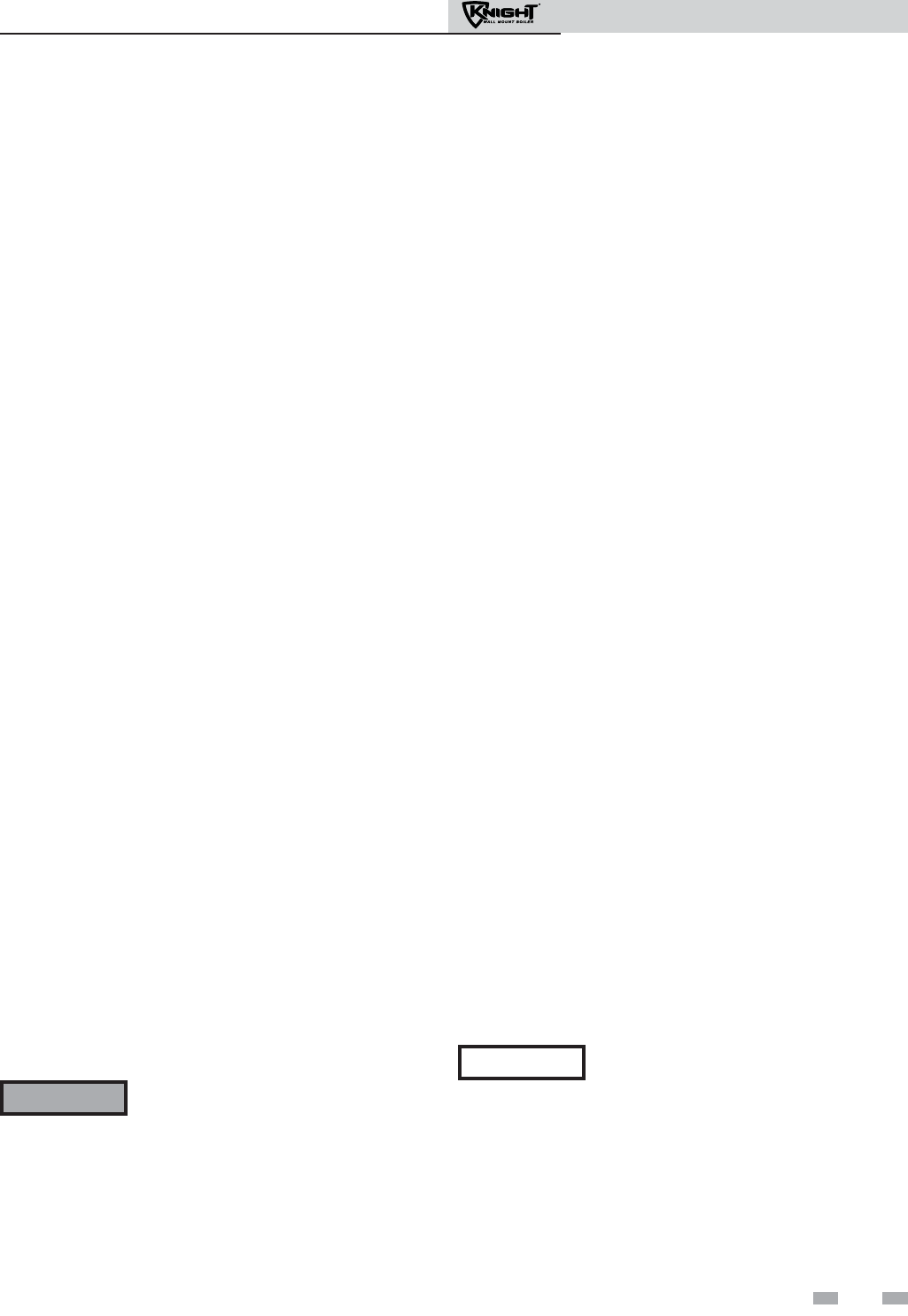
Installation & Operation Manual
33
6 Hydronic piping
System water piping methods
The Knight wall mount is designed to function in a closed
loop pressurized system not less than 12 psi. A temperature
and pressure gauge is included to monitor system pressure
and outlet temperature and should be located on the boiler
outlet.
It is important to note that the boiler has a minimal amount
of pressure drop and must be figured in when sizing the
circulators. Each boiler installation must have an air
elimination device, which will remove air from the system.
Install the boiler so the gas ignition system components are
protected from water (dripping, spraying, etc.) during
appliance operation for basic service of circulator
replacement, valves, and others.
Observe a minimum of 1 inch clearance around all
un-insulated hot water pipes when openings around the pipes
are not protected by non-combustible materials.
Low water cutoff device
On a boiler installed above radiation level, some states and
local codes require a low water cutoff device at the time of
installation.
Chilled water system
If the boiler supplies hot water to heating coils in air handler
units, flow control valves or other devices must be installed to
prevent gravity circulation of heater water in the coils during
the cooling cycle. A chilled water medium must be piped in
parallel with the heater.
Freeze protection
Freeze protection for new or existing systems must use glycol
that is specially formulated for this purpose. This includes
inhibitors, which prevent the glycol from attacking the
metallic system components. Make certain to check that the
system fluid is correct for the glycol concentration and
inhibitor level. The system should be tested at least once a
year and as recommended by the producer of the glycol
solution. Allowance should be made for the expansion of the
glycol solution in the system piping.
General piping information
Basic steps are listed below along with illustrations on the
following pages (FIG.’s 6-3 through 6-10), which will guide you
through the installation of the Knight wall mount boiler
(reference FIG.’s 6-1A and 6-1B).
1. Connect the system return marked “Inlet”.
2. Connect the system supply marked “Outlet”.
3. Install purge and balance valve or shutoff valve and drain on
system return to purge air out of each zone.
4. Install a backflow preventer on the cold feed make-up water
line.
5. Install a pressure reducing valve on the cold feed make-up
water line, (15 psi nominal). Check temperature and
pressure gauge (shipped separately), which should read a
minimum pressure of 12 psi.
6. Install a circulator as shown on the piping diagrams in this
section. Make sure the circulator is properly sized for the
system and friction loss.
7. Install an expansion tank on the system supply. Consult the
tank manufacturer’s instruction for specific information
relating to tank installation. Size the expansion tank for the
required system volume and capacity.
8. Install an air elimination device on the system supply.
9. Install a drain valve at the lowest point of the system.
Note: The boiler cannot be drained completely of water
without purging the unit with an air pressure of 15 psi.
10. This appliance is supplied with a relief valve sized in
accordance with ASME Boiler and Pressure Vessel Code,
Section IV (“Heating Boilers”). The safety relief valve is
installed at the factory located on the left-hand side of the
boiler. Pipe the discharge of the safety relief valve to prevent
injury in the event of pressure relief. Pipe the discharge to
a drain. Provide piping that is the same size as the safety
relief valve outlet. Never block the outlet of the safety relief
valve.
See the *piping illustrations included in this section, FIG.’s 6-3
through 6-10 for suggested guidelines in piping the Knight wall
mount boiler with either zone valves or circulator pumps.
*Please note that these illustrations are
meant to show system piping concept only,
the installer is responsible for all equipment
and detailing required by local codes.
Use only inhibited propylene glycol
solutions, which are specifically
formulated for hydronic systems. Ethylene
glycol is toxic and can attack gaskets and
seals used in hydronic systems.
WARNING
NOTICE

Installation & Operation Manual
34
6 Hydronic piping
Near boiler piping components
1. Boiler system piping:
Boiler system piping MUST be sized per the pipe
requirements listed in Table 6A. Reducing the pipe size
can restrict the flow rate through the boiler, causing
inadvertent high limit shutdowns and poor system
performance. Flow rates are based on 20 feet of piping,
4 - 90° elbows, and 2 - fully ported ball valves.
2. Boiler circulating pump:
A Grundfos UPS26-99F pump will be provided by the
factory (for standard altitude models) as the boiler
circulation pump based on 20 feet of piping, 4 - 90°
elbows, and 2 - fully ported ball valves.
Knight wall mount boilers are capable of controlling a
variable speed boiler circulator. Variable speed
circulators MUST be sized to meet the specified
minimum flow requirements listed in FIG. 6-2 on page 36
at full speed.
3. Domestic hot water circulating pump:
Field supplied. The pump MUST be sized to meet
the specified minimum flow requirements listed in
FIG. 6-2. Consult the indirect water heater operating
guide to determine flow characteristics for the selected
product used.
4. Boiler isolation valves:
Field supplied. Full port ball valves are required. Failure
to use full port ball valves could result in a restricted flow
rate through the boiler.
5. Check valves:
Field supplied. Check valves are recommended for
installation as shown in FIG.’s 6-3 through 6-10. Failure
to install check valves could result in a reverse flow
condition during pump(s) off cycle.
6. Domestic indirect hot water isolation valves:
Field supplied. Full port ball valves are
required. Failure to use full port ball valves could
result in a restricted flow rate through the boiler.
7. Anti-scald mixing valve:
Field supplied. An anti-scald mixing valve is
recommended when storing domestic hot water above
115°F.
8. Unions:
Field supplied. Recommended for unit serviceability.
9. Temperature and pressure gauge:
Factory supplied. The temperature and pressure gauge is
shipped loose. It is the responsibility of the contractor to
install the temperature and pressure gauge on the boiler
water outlet.
10. Pressure relief valve:
Factory supplied. The pressure relief valve is sized to
ASME specifications.
11. Boiler purge valve:
Field supplied. The boiler purge valve is used to
remove entrapped air from the heat exchanger during
start-up.
12. System temperature sensor:
Lochinvar supplies a system temperature sensor.
The sensor is to be installed in the heating loop
downstream from the boiler hot water piping and
heating loop junction. Typically the sensor will be
located far enough downstream to sense system diluted
water temperature.
13. Indirect water heaters:
The Knight wall mount boiler may be piped to an indirect
water heater to heat domestic hot water with the space heat
transfer medium. As depicted in the piping diagrams on
page 38 thru 45, there are two options when utilizing an
indirect water heater.
A. The space heating piping will branch off to flow the
space heat transfer medium through a single wall
heat exchanger coil inside the indirect water heater.
B. The indirect water heater is connected to the system
supply piping. A pump controlled by the Knight
(wall mount) boiler’s control will regulate the flow of
water through the indirect water heater. The indirect
water heater’s temperature will be regulated by the
Knight (wall mount) boiler’s control.
The Knight wall mount boiler is pre-configured to control
the operation of the DHW pump with Domestic Hot Water
Prioritization programming. The DHW programming is
designed to control and balance the space heating
demand by switching between DHW and space heating.
Lochinvar offers the Squire which is a series of indirect
water heaters. The Squire features a stainless steel vessel
with a single wall stainless steel heat exchanger.
WARNING The National Standard Plumbing Code, the
National Plumbing Code of Canada and the
Uniform Plumbing Code limit the pressure
of the heat transfer fluid to less than the
minimum working pressure of the potable
water system up to 30 psi maximum. Also,
the heat transfer fluid must be water or other
non-toxic fluid having a toxicity of Class 1,
as listed in Clinical Toxicology of
Commercial Products, 5th Edition.
14. Y-Strainer:
Field supplied. A Y-strainer or equivalent multipurpose
strainer is recommended at the inlet of the heat exchanger
to remove system particles from older hydronic systems and
protect newer systems.
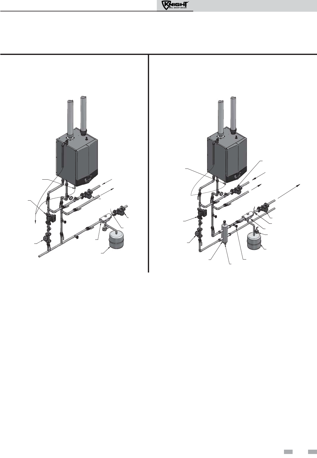
Installation & Operation Manual
35
Near boiler piping connections
VENT AIR
Y-ST RAI NE R
(RECOMMENDED)
DOMESTIC
HOT WATER
PUMP
CONDENSATE
DRAIN
SYSTEM
PUMP
BOILER
PUMP
FROMSY
STEMTOSYSTEM
TO
FROM
INDIRECT
DOMESTIC
HOT WATER
TANK
TO FLOOR
DRAIN
AIR
SEPARATOR
EXPANSION TANK
SYSTEM
SENSOR
Figure 6-1A Near Boiler Piping w/Y-Strainer
VENT AIR
TO FLOOR
DRAIN AIR VENT
VALVE
AIR
SEPARATOR
SYSTEM
SENSOR
DRAIN (TYPICAL)
SYSTEM PUMP
LOW LOSS HEADER
(TYPICAL)
CONDENSATE
DRAIN
INDIRECT
DOMESTIC
HOT WATER
TANK
Y- S T R A I N E R
(RECOMMENDED)
DRAIN VALVE
BOILER
PUMP
FILL VALVE
EXPANSION TANK
TOSYSTEM
FROMSYSTEM
FROM
TO
DOMESTIC HOT
WATER PUMP
AIR SEPARATOR
SYSTEM SENSOR
Figure 6-1B Near Boiler Piping w/Low Loss Header
6 Hydronic piping (continued)
Circulator sizing
The Knight wall mount boiler heat exchanger does have a pressure drop, which must be considered in your system design. Refer
to the graph in FIG. 6-2 for pressure drop through the Knight wall mount boiler heat exchanger.
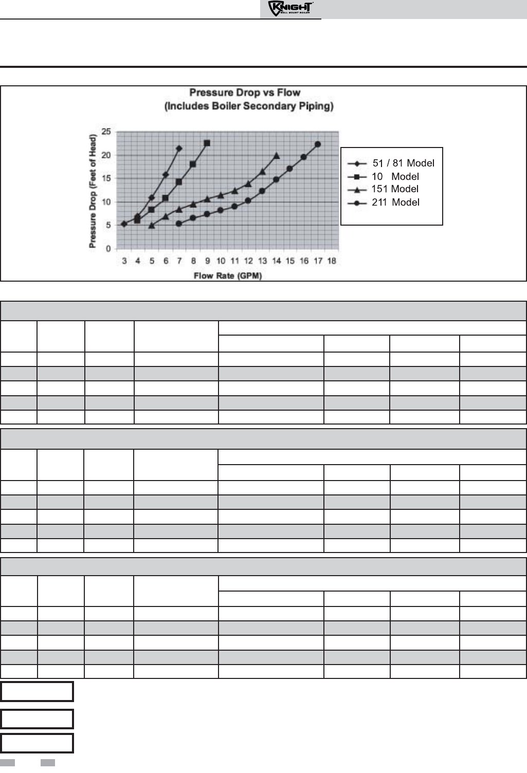
Installation & Operation Manual
36
6 Hydronic piping
6
Figure 6-2 Pressure Drop vs. Flow - Models 50 - 210
20°F Temperature Rise Applications
Model GPM FT/HD Minimum Pipe
Size
Pump
Grundfos TACO B & G Armstrong
51 5.1 11 1" UPS26-99F 0011 NRF-36 E7
81 7.5 24 1" UPS26-99F 0011 NRF-36 E7
106 9.8 27 1" UPS26-99F 0013 NRF-36 E11
151 14.0 20 1" UPS26-99F 0011 NRF-36 E7
211 19.6 29 1" UPS32-160 1400-50 PL-55 E9
Table 6A Circulator Recommendations for Temperature Rise Applications_20°, 25°, and 35°
25°F Temperature Rise Applications
Model GPM FT/HD Minimum Pipe
Size
Pump
Grundfos TACO B & G Armstrong
51 4.1 7.3 1" UPS15-58FC 0014 NRF-36 E7
81 5.9 15.0 1" UPS15-58FC 0014 NRF-36 E7
106 7.7 17.5 1" UPS26-99F 0014 NRF-36 E7
151 11.0 12.8 1" UPS26-99F 0014 NRF-36 E7
211 15.5 19.0 1" UPS26-99F 0013 NRF-36 E7
35°F Temperature Rise Applications
Model GPM FT/HD Minimum Pipe
Size
Pump
Grundfos TACO B & G Armstrong
51 2.9 4.1 1" UPS15-58FC 007 NRF-22 Astro-30
81 4.2 7.3 1" UPS15-58FC 007 NRF-22 Astro-30
106 5.5 9.8 1" UPS15-58FC 007 NRF-22 Astro-30
151 7.9 10 1" UPS15-58FC 008/0010 NRF-36 Astro-30
211 11.0 10.1 1" UPS15-58FC 0010 NRF-36 Astro-50
Pumps listed in bold type are provided by the factory as the boiler circulation pump on standard altitude
models.
NOTICE
Pumps listed in italicized type are provided by the factory as the boiler circulation pump on high altitude
models.
NOTICE
The temperature rise provided by a pump/model combination will decrease by 3% per 1000 feet of elevation.
NOTICE
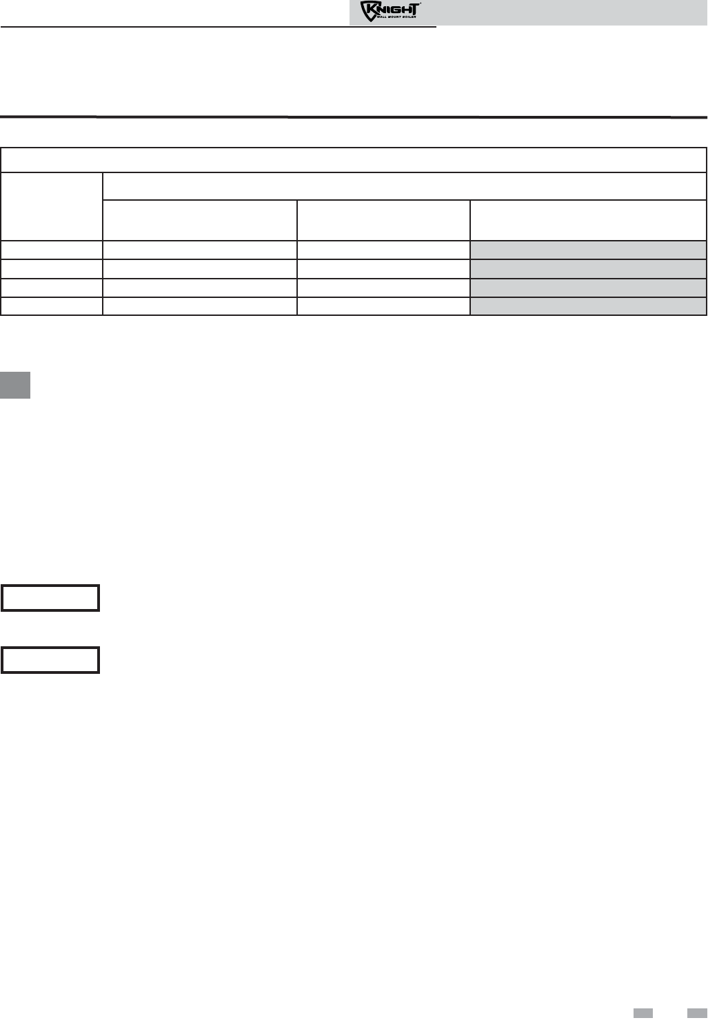
6 Hydronic piping (continued)
It is required that near boiler piping systems
utilize Primary/Secondary configurations as
shown in FIG.’s 6-3 through 6-10 only. The
use of other near boiler piping configurations
could result in improper building and system
flow rates leading to inadvertent boiler high
limit shutdowns and poor system
performance.
NOTICE
Pump sizing and flow requirements are
based on 20 feet of piping, 4 - 90° elbows,
and 2 - fully ported ball valves.
NOTICE
Variable speed pump option
Table 6B Recommended Variable Speed Pumps
*The minimum temperature rise is derived from the chart in FIG. 6-2 with the firing rate and pump speed at 100% as shown in
the table above.
The shaded regions of pump coverage are only available for applications with 230V (60 Hz) supply voltage, all others are
to be 115V. (A field supplied relay is required to connect the 230V pump listed in the shaded area in Table 6B to the boiler
high voltage terminal strip.)
Variable speed pump setup
Before operation, ensure the following:
- Pump is set for an input signal of 0 - 10Vdc by the dip switches on the pump control
- Pump is set for external signal control (if applicable)
- Pump is set for linear output (if applicable)
- If pump does not come equipped with a 0 - 10 Vdc input option, an optional module
will be required from the vendor
37
Installation & Operation Manual
Minimum Temperature Rise*
Model
Pump
Grundfos
UP26-96 FC/VS
TACO
0013 IFC VS
Wilo
Stratos 1.25 3 x 30
51/81 20.3 20.3 21.7
106 22.3 21.0 21.5
151 21.2 19.8 19.1
211 26.8 25.1 23.6
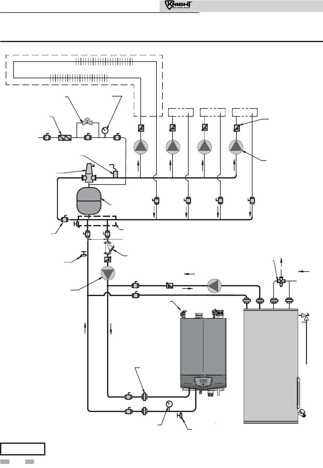
38
Installation & Operation Manual
BOILER
INDIRECT
DHW TANK
DOMESTIC
HOT WATER
CIRCULATOR
BACKFLOW
PREVENTER
PRESSURE
REDUCING VALVE
PRESSURE
GAUGE
ANTI-SCALD
MIXING VALVE
COLD
WATER
IN
TEMPERATURE /
PRESSURE
GAUGE
AIR SEPARATOR
EXPANSION
TANK
BALL VALVE
(TYPICAL)
UNION
(TYPICAL)
DRAIN
DRAIN POINT
(TYPICAL)
MAKE UP WATER
HOT
WATER
OUT
ZONE CIRCULATORS
(TYPICAL)
FLOW CHECK
VALVE
(TYPICAL)
BOILER
CIRCULATOR
SYSTEM SUPPLY
SENSOR
PRESSURE
RELIEF VALVE
Y-STRAINER
(RECOMMENDED)
MAY SUBSTITUTE LOW LOSS HEADER
NOT TO EXCEED 4 PIPE DIA OR MAX. OF 12" APART
ZONE #1
ZONE #2 ZONE #3 ZONE #4
Figure 6-3 Single Boiler - Single Temperature Zoned with Circulators
Please note that these illustrations are meant to show system piping concept only, the installer is responsible
for all equipment and detailing required by local codes.
NOTICE
6 Hydronic piping
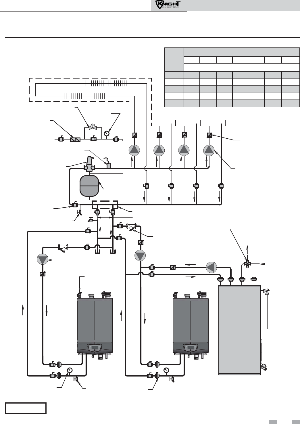
39
Installation & Operation Manual
INDIRECT
DHW TANK
BACKFLOW
PREVENTER
PRESSURE
REDUCING VALVE PRESSURE
GAUGE
ANTI-SCALD
MIXING VALVE
AIR SEPARATOR
EXPANSION
TANK
BALL VALVE
(TYPICAL)
DRAIN POINT
(TYPICAL)
MAKE UP
WATER
ZONE CIRCULATORS
(TYPICAL)
FLOW CHECK
VALVE
(TYPICAL)
NOT TO EXCEED 4 PIPE DIA OR MAX. OF 12" APART
BOILER
CIRCULATOR
BOILER 2
(MEMBER 1)
DOMESTIC
HOT WATER
CIRCULATOR
UNION
(TYPICAL)
PRESSURE
RELIEF VALVE
HOT
WATER
OUT
COLD
WATER
IN
BOILER 1
(LEADER)
SYSTEM SUPPLY
SENSOR
TEMPERATURE /
PRESSURE
GAUGE
DRAIN
Y-STRAINER
(RECOMMENDED)
(TYPICAL)
MAY SUBSTITUTE LOW LOSS HEADER
ZONE #1
ZONE #2 ZONE #3 ZONE #4
Figure 6-4 Multiple Boilers - Single Temperature Zoned with Circulators
Model
Number of Units
2 3 4 5 6 7 8
Required Pipe Sizes
51 1" 1-1/4" 1-1/2" 2" 2" 2" 2"
81 1-1/4" 1-1/2" 2" 2" 2-1/2" 2-1/2" 2-1/2"
106 1-1/2" 2" 2" 2-1/2" 2-1/2" 2-1/2" 3"
151 2" 2" 2-1/2" 2-1/2" 3" 3-1/2" 3-1/2"
211 2" 2-1/2" 3" 3-1/2" 3-1/2" 4" 4"
Please note that these illustrations are meant to show system piping concept only, the installer is responsible
for all equipment and detailing required by local codes.
NOTICE
6 Hydronic piping (continued)

40
Installation & Operation Manual
6 Hydronic piping
BOILER
INDIRECT
DHW TANK
DOMESTIC
HOT WATER
CIRCULATOR
ANTI-SCALD
MIXING VALVE
COLD
WATER
IN
TEMPERATURE /
PRESSURE
GAUGE
AIR SEPARATOR
BALL VALVE
(TYPICAL)
UNION
(TYPICAL)
DRAIN POINT
(TYPICAL)
MAKE
UP
WATER
HOT
WATER
OUT
BOILER
CIRCULATOR
BACKFLOW
PREVENTER
PRESSURE
REDUCING VALVE
PRESSURE
GAUGE
EXPANSION
TANK
MIXING VALVES
(TYPICAL)
FLOW CHECK
VALVE
SYSTEM
SUPPLY
SENSOR
DRAIN
Y-STRAINER
(RECOMMENDED)
MAY SUBSTITUTE
LOW LOSS HEADER
TEMPERATURE
LOOP #1
TEMPERATURE
LOOP #2
TEMPERATURE
LOOP #3
NOT TO EXCEED 4 PIPE DIA
OR MAX. OF 12" APART
Figure 6-5 Single Boiler - Multiple Temperatures
Please note that these illustrations are meant to show system piping concept only, the installer is responsible
for all equipment and detailing required by local codes.
NOTICE
CAUTION Mixing valves are required for the protection of low temperature loops.
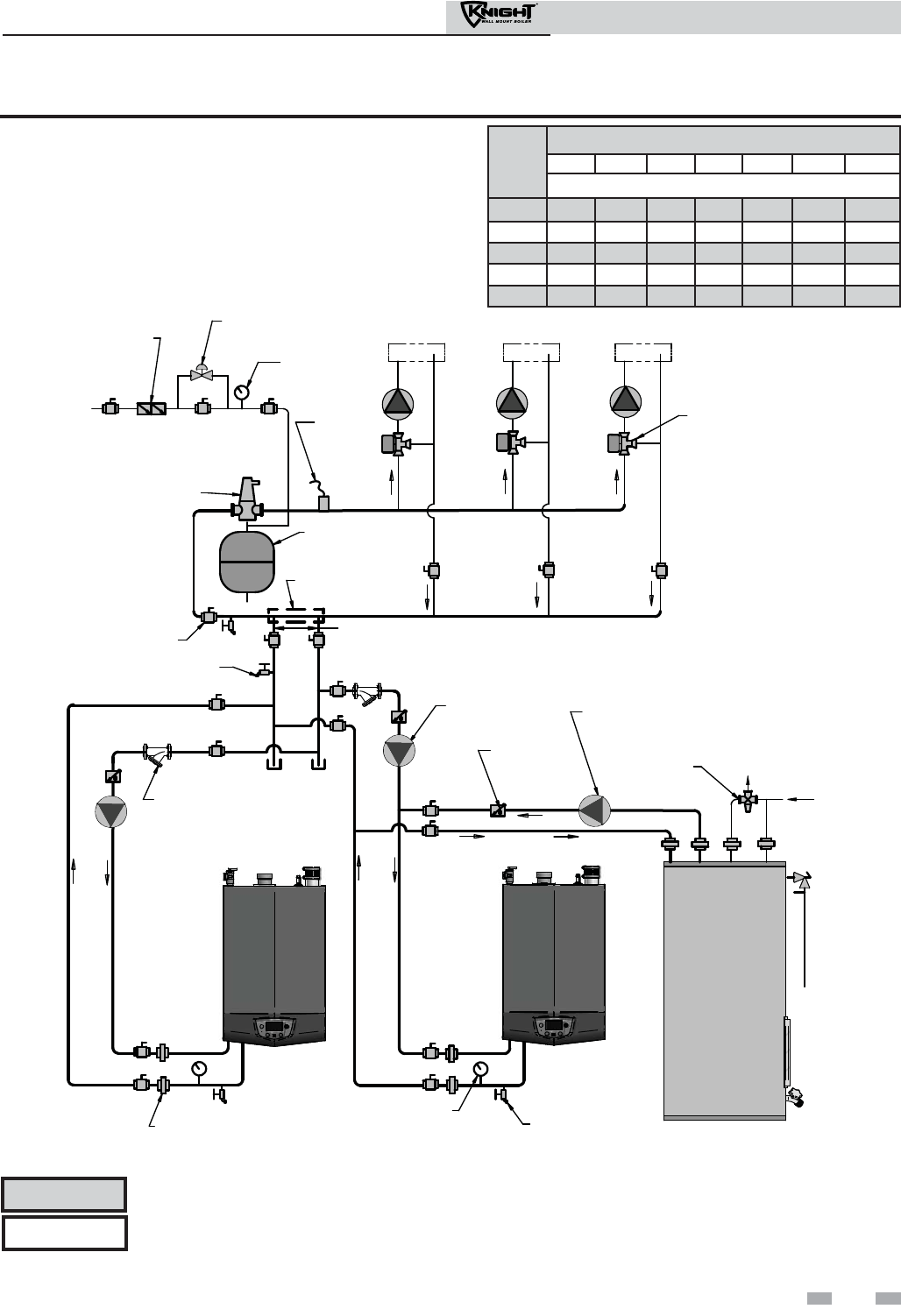
6 Hydronic piping (continued)
DOMESTIC
HOT WATER
CIRCULATOR
ANTI-SCALD
MIXING VALVE
COLD
WATER
IN
AIR SEPARATOR
BALL VALVE
(TYPICAL)
DRAIN POINT
(TYPICAL)
MAKE
UP
WATER
HOT
WATER
OUT
BOILER
CIRCULATOR
BACKFLOW
PREVENTER
PRESSURE
REDUCING VALVE
PRESSURE
GAUGE
EXPANSION
TANK
MIXING VALVES
(TYPICAL)
FLOW CHECK
VALVE
SYSTEM
SUPPLY
SENSOR
MAY SUBSTITUTE
LOW LOSS HEADER
TEMPERATURE
LOOP #1
TEMPERATURE
LOOP #2
TEMPERATURE
LOOP #3
BOILER
INDIRECT
DHW TANK
TEMPERATURE /
PRESSURE
GAUGE
UNION
(TYPICAL)
DRAIN
Y-STRAINER
(RECOMMENDED)
NOT TO EXCEED 4 PIPE DIA OR MAX. OF 12" APART
BOILER
Figure 6-6 Multiple Boilers - Multiple Temperatures
Please note that these illustrations are meant to show system piping concept only, the installer is responsible
for all equipment and detailing required by local codes.
NOTICE
Model
Number of Units
2 3 4 5 6 7 8
Required Pipe Sizes
51 1" 1-1/4" 1-1/2" 2" 2" 2" 2"
81 1-1/4" 1-1/2" 2" 2" 2-1/2" 2-1/2" 2-1/2"
106 1-1/2" 2" 2" 2-1/2" 2-1/2" 2-1/2" 3"
151 2" 2" 2-1/2" 2-1/2" 3" 3-1/2" 3-1/2"
211 2" 2-1/2" 3" 3-1/2" 3-1/2" 4" 4"
41
Installation & Operation Manual
CAUTION Mixing valves are required for the protection of low temperature loops.
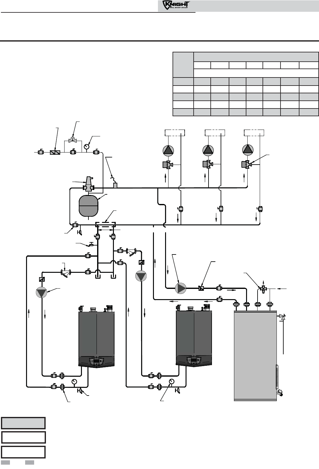
6 Hydronic piping
Figure 6-7 Multiple Boilers - Multiple Temperatures with DHW Piped as a Zone
DOMESTIC
HOT WATER
CIRCULATOR
ANTI-SCALD
MIXING VALVE
COLD
WATER
IN
AIR SEPARATOR
BALL VALVE
(TYPICAL)
DRAIN POINT
(TYPICAL)
MAKE
UP
WATER
HOT
WATER
OUT
BOILER
CIRCULATOR
BACKFLOW
PREVENTER
PRESSURE
REDUCING VALVE
PRESSURE
GAUGE
EXPANSION
TANK
MIXING VALVES
(TYPICAL)
FLOW CHECK
VALVE
SYSTEM
SUPPLY
SENSOR
MAY SUBSTITUTE
LOW LOSS HEADER
TEMPERATURE
LOOP #1
TEMPERATURE
LOOP #2
TEMPERATURE
LOOP #3
BOILER
INDIRECT
DHW TANK
UNION
(TYPICAL)
DRAIN
Y-STRAINER
(RECOMMENDED)
NOT TO EXCEED 4 PIPE DIA OR MAX. OF 12" APART
BOILER
TEMPERATURE /
PRESSURE GAUGE
Please note that these illustrations are meant to show system piping concept only, the installer is responsible
for all equipment and detailing required by local codes.
NOTICE
Model
Number of Units
2 3 4 5 6 7 8
Required Pipe Sizes
51 1" 1-1/4" 1-1/2" 2" 2" 2" 2"
81 1-1/4" 1-1/2" 2" 2" 2-1/2" 2-1/2" 2-1/2"
106 1-1/2" 2" 2" 2-1/2" 2-1/2" 2-1/2" 3"
151 2" 2" 2-1/2" 2-1/2" 3" 3-1/2" 3-1/2"
211 2" 2-1/2" 3" 3-1/2" 3-1/2" 4" 4"
42
Installation & Operation Manual
Please note that the installer is responsible for ensuring DHW prioritization when piped as a zone.
NOTICE
CAUTION Mixing valves are required for the protection of low temperature loops.
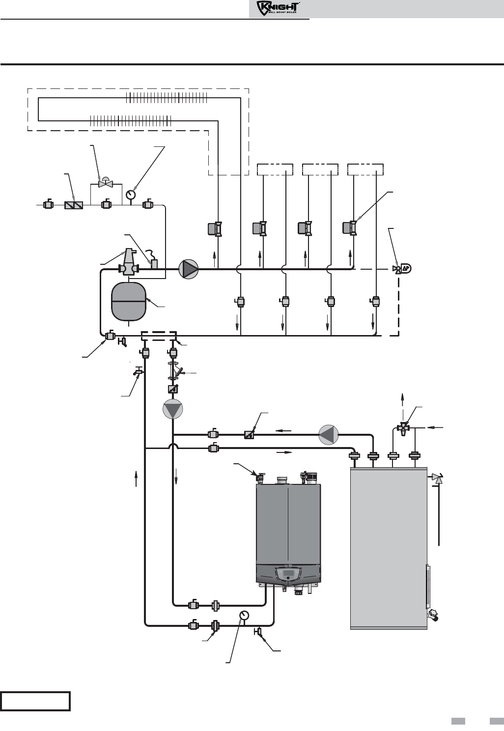
Installation & Operation Manual
43
6 Hydronic piping (continued)
BOILER
INDIRECT
DHW TANK
DOMESTIC
HOT WATER
CIRCULATOR
ANTI-SCALD
MIXING VALVE
COLD
WATER
IN
TEMPERATURE /
PRESSURE
GAUGE
AIR SEPARATOR
BALL VALVE
(TYPICAL)
UNION
(TYPICAL)
PRESSURE
RELIEF VALVE
DRAIN POINT
(TYPICAL)
MAKE UP WATER
HOT
WATER
OUT
BOILER
CIRCULATOR
BACKFLOW
PREVENTER
PRESSURE
REDUCING VALVE PRESSURE
GAUGE
EXPANSION
TANK
ZONE VALVES
(TYPICAL)
FLOW CHECK
VALVE
DIFFERENTIAL
PRESSURE BYPASS
VALVE (IF USED)
SYSTEM
CIRCULATOR
SYSTEM SUPPLY
SENSOR
DRAIN
Y-STRAINER
(RECOMMENDED)
MAY SUBSTITUTE LOW LOSS HEADER
ZONE #1
ZONE #2 ZONE #3 ZONE #4
Figure 6-8 Single Boiler Zoned with Valves
Please note that these illustrations are meant to show system piping concept only, the installer is responsible
for all equipment and detailing required by local codes.
NOTICE

Installation & Operation Manual
44
6 Hydronic piping
INDIRECT
DHW TANK
BACKFLOW
PREVENTER
PRESSURE
REDUCING VALVE
PRESSURE
GAUGE
ANTI-SCALD
MIXING VALVE
TEMPERATURE /
PRESSURE
GAUGE
AIR SEPARATOR
EXPANSION
TANK
BALL VALVE
(TYPICAL)
DRAIN POINT
(TYPICAL)
MAKE UP WATER
ZONE VALVES
(TYPICAL)
BOILER
CIRCULATOR
BOILER 2
(MEMBER 1)
DOMESTIC
HOT WATER
CIRCULATOR
UNION
(TYPICAL)
PRESSURE
RELIEF VALVE
HOT
WATER
OUT
COLD
WATER
IN
BOILER 1
(LEADER)
DIFFERENTIAL
PRESSURE BYPASS
VALVE (IF USED)
SYSTEM SUPPLY
SENSOR
SYSTEM
CIRCULATOR
DRAIN
Y-STRAI N E R
(RECOMMENDED)
(TYPICAL)
NOT TO EXCEED 4 PIPE DIA OR MAX. OF 12" APART
MAY SUBSTITUTE LOW LOSS HEADER
ZONE #1
ZONE #2 ZONE #3 ZONE #4
FLOW CHECK
VALVE
Figure 6-9 Multiple Boilers Zoned with Valves
Model
Number of Units
2 3 4 5 6 7 8
Required Pipe Sizes
51 1" 1-1/4" 1-1/2" 2" 2" 2" 2"
81 1-1/4" 1-1/2" 2" 2" 2-1/2" 2-1/2" 2-1/2"
106 1-1/2" 2" 2" 2-1/2" 2-1/2" 2-1/2" 3"
151 2" 2" 2-1/2" 2-1/2" 3" 3-1/2" 3-1/2"
211 2" 2-1/2" 3" 3-1/2" 3-1/2" 4" 4"
Please note that these illustrations are meant to show system piping concept only, the installer is responsible
for all equipment and detailing required by local codes.
NOTICE
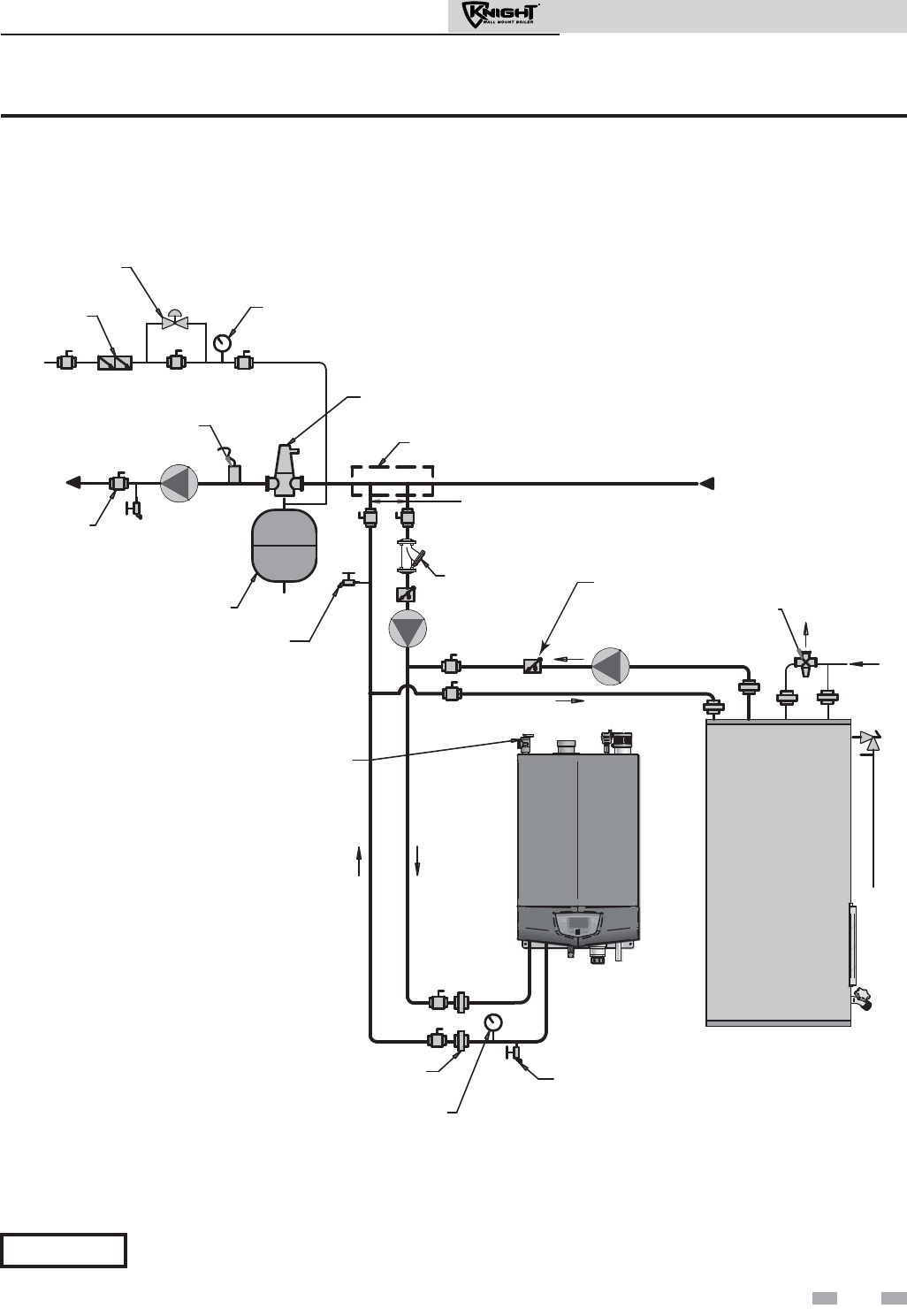
Installation & Operation Manual
45
BOILER
INDIRECT
DHW TANK
DOMESTIC
HOT WATER
CIRCULATOR
BACKFLOW
PREVENTER
PRESSURE
REDUCING VALVE
PRESSURE
GAUGE
ANTI-SCALD
MIXING VALVE
COLD
WATER
IN
TEMPERATURE /
PRESSURE
GAUGE
AIR
SEPARATOR
EXPANSION
TANK
BALL VALVE
(TYPICAL)
UNION
(TYPICAL)
PRESSURE
RELIEF VALVE
DRAIN POINT
(TYPICAL)
MAKE UP WATER
FROM
SYSTEM
NOT TO EXCEED 4 PIPE DIA OR MAX. OF 12" APART
BOILER
CIRCULATOR
SYSTEM
CIRCULATOR
TO
SYSTEM
SYSTEM SUPPLY
SENSOR
DRAIN
MAY SUBSTITUTE LOW LOSS HEADER
Y-STRAINER
(RECOMMENDED)
HOT
WATER
OUT
FLOW CHECK VALVE
Figure 6-10 Single Boiler - Non-Zoned Primary/Secondary Piping
6 Hydronic piping (continued)
Please note that these illustrations are meant to show system piping concept only, the installer is responsible
for all equipment and detailing required by local codes.
NOTICE
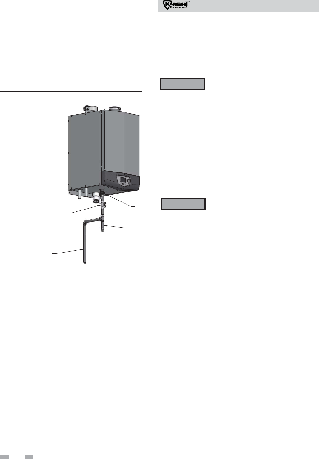
7 Gas connections
Connecting gas supply piping
1. Remove the front access panel and refer to FIG. 7-1 to
pipe gas to the boiler.
a. Install a field supplied sediment trap / drip leg
upstream of the boiler gas controls.
MANUAL SHUTOFF VALVE
(FIELD SUPPLIED)
UNION
DRIP LEG
GAS SUPPLY
Figure 7-1 Gas Supply Piping
2. Support piping with hangers, not by the boiler or its
accessories.
Do not check for gas leaks with an open
flame – use the bubble test. Failure to use
the bubble test or check for gas leaks can
cause severe personal injury, death, or
substantial property damage.
3. Purge all air from the gas supply piping.
4. Before placing the boiler in operation, check the boiler and
its gas connection for leaks.
a. Close manual main shutoff valve during any
pressure testing at less than 13 inches w.c.
b. Disconnect the boiler and gas valve from the gas
supply piping during any pressure testing greater
than 13 inches w.c.
The gas valve and blower will not support
the weight of the piping. Do not attempt to
support the weight of the piping with the
boiler or its accessories. Failure to comply
could result in severe personal injury, death,
or substantial property damage.
WARNING
WARNING
5. Use pipe sealing compound compatible with propane gases.
Apply sparingly only to male threads of the pipe joints so
that pipe dope does not block gas flow.
46
Installation & Operation Manual

7 Gas connections (continued)
Failure to apply pipe sealing compound
as detailed in this manual can result in
severe personal injury, death, or
substantial property damage.
Knight wall mount boilers are typically
shipped ready to fire on natural gas.
Check boiler rating plate to determine
which fuel the boiler is set for. If set to
natural gas, it may be converted to LP by
installing an orifice (see page 13). In
order to operate on LP gas, an orifice
MUST BE installed. Failure to comply
could result in severe personal injury,
death, or substantial property damage.
Use two wrenches when tightening gas
piping at boiler (FIG. 7-2), using one
wrench to prevent the boiler gas line
connection from turning. Failure to
support the boiler gas connection pipe to
prevent it from turning could damage gas
line components.
USE BACKUP WRENCH
TO PREVENT PIPE FROM
ROTATING
Figure 7-2 Inlet Pipe with Backup Wrench
Natural gas:
Pipe sizing for natural gas
1. Refer to Table 7A for pipe length and diameter. Based on
rated boiler input (divide by 1,000 to obtain cubic feet per
hour).
a. Table 7A is only for natural gas with specific gravity
0.60 inches, with a pressure drop through the gas
piping of 0.5 inches w.c.
b. For additional gas pipe sizing information, refer to
ANSI Z223.1 (or B149.1 for Canadian installations).
Natural gas supply pressure requirements
1. Pressure required at the gas valve inlet pressure port:
• Maximum 14 inches w.c. with no flow (lockup) or with
boiler on.
• Minimum 4 inches w.c. with gas flowing (verify during
boiler startup).
2. Install 100% lockup gas pressure regulator in supply line if
inlet pressure can exceed 14 inches w.c. at any time. Adjust
lockup regulator for 14 inches w.c. maximum.
Propane Gas:
Pipe sizing for propane gas
1. Contact gas supplier to size pipes, tanks, and 100%
lockup gas pressure regulator.
Propane Supply Pressure Requirements
1. Adjust propane supply regulator provided by the gas
supplier for 14 inches w.c. maximum pressure.
2. Pressure required at gas valve inlet pressure port:
• Maximum 14 inches w.c. with no flow (lockup) or with
boiler on.
• Minimum 8 inches w.c. with gas flowing (verify during
boiler startup).
Maximum inlet gas pressure must not
exceed the value specified. Minimum
value listed is for the purposes of input
adjustment.
WARNING
WARNING
WARNING
WARNING Knight wall mount boilers are typically
shipped ready to fire on natural gas. Check
boiler rating plate to determine which fuel
the boiler is set for. If set to natural gas, it
may be converted to LP by installing an
orifice (see page 13). In order to operate on
LP gas, an orifice MUST BE installed. Failure
to comply could result in severe personal
injury, death, or substantial property damage.
NOTICE
WARNING Ensure that the high gas pressure regulator
is at least 6 - 10 feet upstream of the
appliance.
47
Installation & Operation Manual

48
Installation & Operation Manual
7 Gas connections
Nominal
Iron Pipe
Size (Inches)
Natural Gas Pipe Capacity Chart
Length of Pipe in Straight Feet for 1/2 PSI
10
20
30
40
50
60
70
80
90
100
125
150
175
200
1/2
175 120 97 82 N/A N/A N/A N/A N/A N/A N/A N/A N/A N/A
3/4
369
256
205
174
155
141
128
121
113
106
95
86
79
74
1
697
477
384
328
292
267
246
236
210
200
179
164
149
138
1-1/4
1400
974
789
677
595
543
502
472
441
410
369
333
308
287
1-1/2
2150
1500
1210
1020
923
830
769
707
666
636
564
513
472
441
2
4100
2820
2260
1950
1720
1560
1440
1330
1250
1180
1100
974
871
820
2-1/2
6460
4460
3610
3100
2720
2460
2310
2100
2000
1900
1700
1540
1400
1300
3
11200
7900
6400
5400
4870
4410
4000
3800
3540
3330
3000
2720
2500
2340
4
23500
16100
13100
11100
10000
9000
8300
7690
7380
6870
6150
5640
5130
4720
Knight wall mount boilers are typically shipped ready to fire on natural gas. Check boiler rating plate to
determine which fuel the boiler is set for. If set to natural gas, it may be converted to LP by installing an orifice
(see page 13). In order to operate on LP gas, an orifice MUST BE installed. Failure to comply could result in
severe personal injury, death, or substantial property damage.
Table 7A Natural Gas Pipe Size Chart
The gas piping must be sized for the proper flow and length
of pipe, to avoid excessive pressure drop. Both the gas meter
and the gas regulator must be properly sized for the total gas
load.
If you experience a pressure drop greater than 1 inch w.c.,
the meter, regulator, or gas line is undersized or in need of
service. Perform the steps below when checking inlet gas
supply:
1. Turn the main power switch to the “OFF” position.
2. Shut off gas supply at the manual gas valve in the gas
piping to the appliance.
WARNING
3. Loosen the set screw one (1) full turn from inside the
pressure tap on top of the gas valve. Place the tubing of
the manometer over the tap once the set screw is
loosened as shown in FIG. 7-3.
4. Slowly turn on the gas supply at the field installed
manual gas valve.
5. Turn the power switch to the “ON” position.
6. Adjust the temperature set point on the control panel of
the SMART SYSTEM control module to call for heat.
7. Observe the gas supply pressure as the burner fires at
100% of rated input. Percent of burner input will be
displayed on the control panel.
8. Ensure inlet pressure is within specified range.
Minimum and maximum gas supply pressures are
specified in this section of the manual.
9. If gas supply pressure is within normal range and no
adjustments are needed, proceed on to Step 11.
10. If the gas pressure is out of range, contact the gas utility,
gas supplier, qualified installer or service agency to
determine the necessary steps to provide proper gas
pressure to the control.
11. Turn the power switch to the “OFF” position.
12. Shut off the gas supply at the manual gas valve in the gas
piping to the appliance.
13. Remove the manometer from the pressure tap on top of
the gas valve. Re-tighten the set screw inside the pressure
tap.
Check inlet gas supply
NOTICE CSA or UL listed flexible gas
connections are acceptable, but you
must exercise caution to ensure that the
line has adequate capacity to allow your
boiler to fire at full rate. Consult with
local codes for proper installation or
service procedures.
DO NOT adjust or attempt to measure
gas valve outlet pressure. The gas valve is
factory-set for the correct outlet
pressure. This setting is suitable for
natural gas and propane, requiring no
field adjustment. Attempting to alter or
measure the gas valve outlet pressure
could result in damage to the valve,
causing potential severe personal injury,
death, or substantial property damage.
WARNING
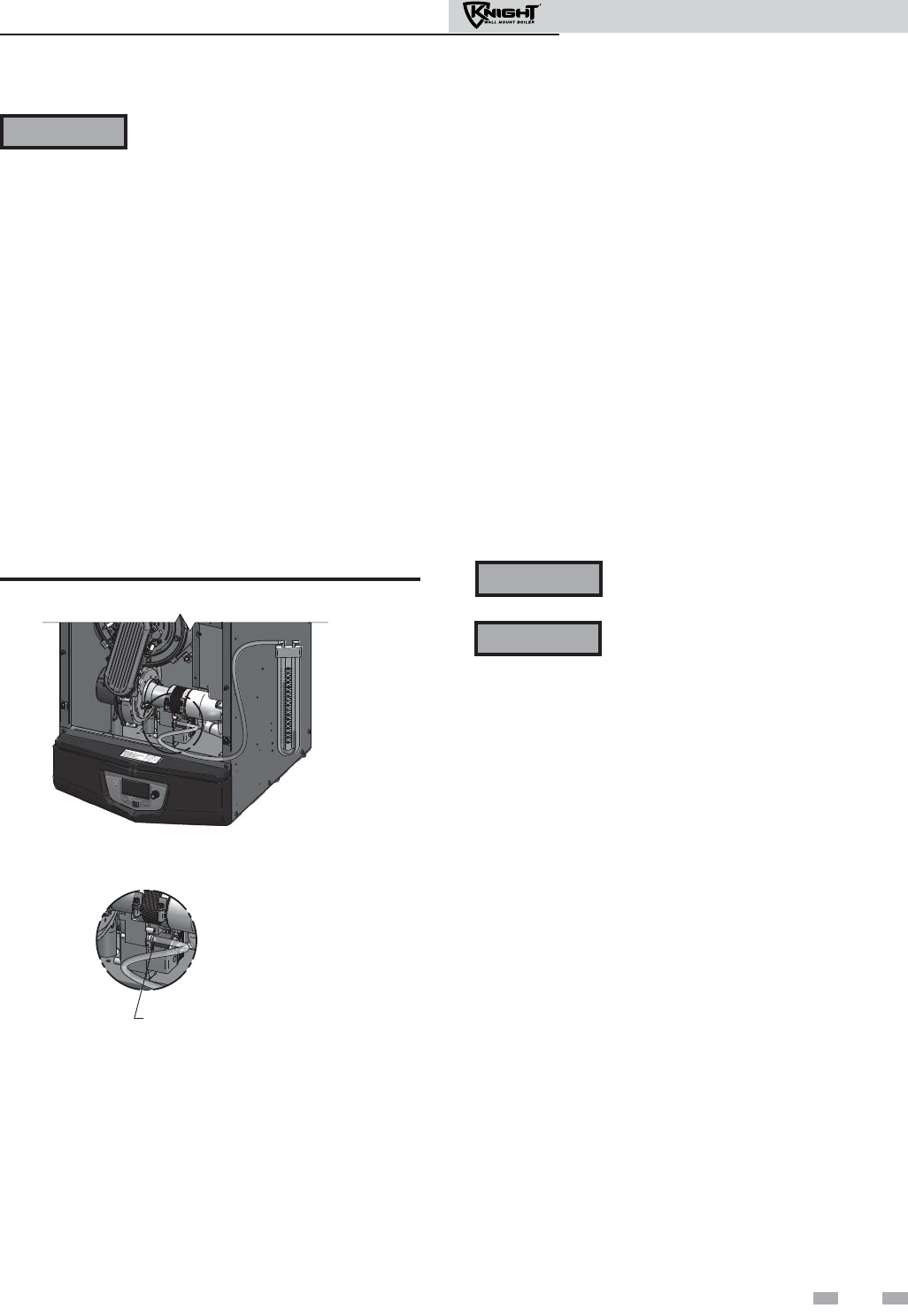
49
Installation & Operation Manual
7 Gas connections (continued)
WARNING When re-tightening the set screw, be
sure to tighten securely to prevent gas
leaks.
Do not check for gas leaks with an open
flame -- use the bubble test. Failure to
use the bubble test or check for gas leaks
can cause severe personal injury, death,
or substantial property damage.
14. Turn on the gas supply at the manual gas valve.
15. Turn the power switch to the “ON” position.
16. Adjust the temperature set point on the control panel
of the SMART SYSTEM control module to the desired
water temperature so the appliance will call for heat.
17. Check burner performance by cycling the system while
you observe burner response. The burner should
ignite promptly. Flame pattern should be stable. Turn
system off and allow burner to cool, then cycle burner
again to ensure proper ignition and flame
characteristics.
Gas Pressure
The gas pressure must remain between 4 inches w.c. (natural),
8 inches w.c. (LP) minimum and 14 inches w.c. (natural and LP)
maximum during stand-by (static) mode and while in operating
(dynamic) mode. If an in-line regulator is used, it must be a
minimum of 10 feet from the Knight wall mount boiler. It is
very important that the gas line is properly purged by the gas
supplier or utility company. Failure to properly purge the lines
or improper line sizing, will result in ignition failure.
The problem is especially noticeable in NEW LP installations
and also in empty tank situations. This can also occur when a
utility company shuts off service to an area to provide
maintenance to their lines.
Gas valve replacement
The gas valve MUST NOT be replaced with a conventional gas
valve under any circumstances. As an additional safety feature,
this gas valve has a flanged connection to the venturi and blower.
DETAIL
LOOSEN SET SCREW ONE (1)
FULL TURN THEN PLACE
TUBING OVER PRESSURE TAP
Figure 7-3 Inlet Gas Supply Check
DO NOT adjust or attempt to measure gas
valve outlet pressure. The gas valve is
factory-set for the correct outlet pressure.
This setting is suitable for natural gas and
propane, requiring no field adjustment.
Attempting to alter or measure the gas
valve outlet pressure could result in
damage to the valve, causing potential
severe personal injury, death, or
substantial property damage.
Failure to follow all precautions could
result in fire, explosion, or death!
WARNING
WARNING
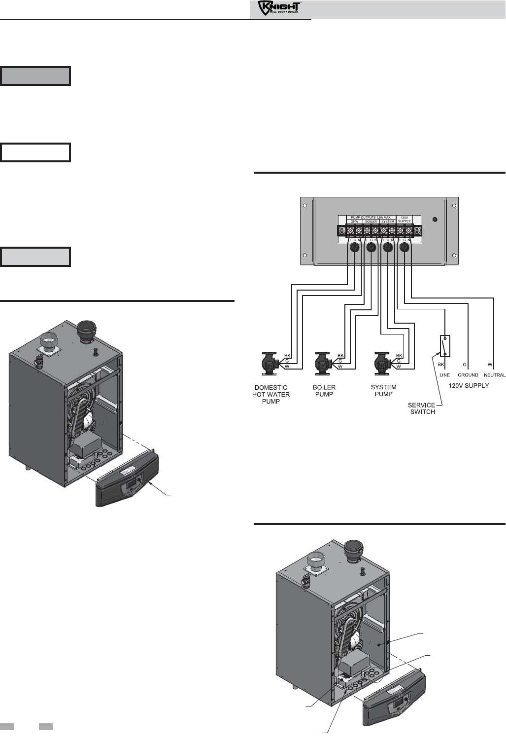
8 Field wiring
ELECTRICAL SHOCK HAZARD – For
your safety, turn off electrical power
supply before making any electrical
connections to avoid possible electric
shock hazard. Failure to do so can cause
severe personal injury or death.
Wiring must be N.E.C. Class 1.
If original wiring as supplied with boiler
must be replaced, use only type 105°C
wire or equivalent.
Boiler must be electrically grounded as
required by National Electrical Code
ANSI/NFPA 70 – latest edition.
Installation must comply with:
1. National Electrical Code and any other national, state,
provincial, or local codes, or regulations.
2. In Canada, CSA C22.1 Canadian Electrical Code Part 1,
and any local codes.
3. Wire the boiler pump as shown in FIG. 8-2.
4. When connecting a domestic hot water (DHW) pump,
connect the wiring to the line voltage terminal strip as
shown in FIG. 8-2.
5. To activate a system pump, wire as shown in FIG. 8-2. If the
motor is larger than 1/8 hp or 1.8 amps, you must isolate
with a relay.
Figure 8-2 Line Voltage Field Wiring Connections
Label all wires prior to disconnection
when servicing controls. Wiring errors
can cause improper and dangerous
operation.
WARNING
NOTICE
CAUTION
REMOVE BEZE
L
Figure 8-1 Remove Bezel
Low voltage connections
1. Route all low voltage wires through the knockouts in the
bottom front right side, just under the control panel, as
shown in FIG. 8-3.
2. Connect low voltage wiring to low voltage connection board
as shown in FIG. 8-4 on page 53 of this manual and the
boiler wiring diagram.
LOW VOLTAGE
WIRING KNOCKOUTS
LOW VOLTAGE
CONNECTION BOARD
LINE VOLTAGE
WIRING KNOCKOUTS
LINE VOLTAGE
JUNCTION BOX
Figure 8-3 Routing Field Wiring
Line voltage connections
1. Remove bezel as shown in FIG. 8-1.
2. Connect 120 vac power wiring to the line voltage terminal
strip in the junction box, as shown in FIG. 8-2.
2. Provide and install a fused disconnect or service switch
(15 amp recommended) as required by the code (see
FIG. 8-2).
50
Installation & Operation Manual

51
Installation & Operation Manual
8 Field wiring (continued)
Thermostat
1. Connect the room thermostat or end switch (isolated
contact only) to room thermostat 1, 2, or 3, as shown in
FIG. 8-4.
2. Install the thermostat on the inside wall away from
influences of drafts, hot or cold water pipes, lighting
fixtures, television, sunlight, or fireplaces.
3. Thermostat anticipator (if applicable):
a. If connected directly to boiler, set for 0.1 amps.
b. If connected to relays or other devices, set to
match total electrical power requirements of
connected devices. See device manufacturers’
specifications and thermostat instructions for
details.
Outdoor temperature sensor
1. Mount the sensor on an exterior wall, shielded from
direct sunlight or flow of heat or cooling from other
sources.
2. Route sensor wires through a knockout in the bottom
front right side of the boiler (see FIG. 8-3).
3. Connect outdoor temperature sensor (FIG. 8-4) to the
outdoor sensor terminals on the connection board to
enable outdoor reset operation of the Knight wall mount
boiler. If fixed temperature operation is required, do not
install outdoor sensor.
DHW thermostat
1. Connect storage indirect water heater (DHW)
thermostat (FIG. 8-4) to the DHW thermostat terminals
on the connection board. If a tank sensor is connected
(see DHW Tank Sensor below) the tank thermostat is
ignored.
Louver relay
1. If louvers need to operate when the boiler fires, they can be
controlled by this output. Connect these terminals to a 24
vac relay coil, which is wired to operate the louvers
(FIG. 8-4).
Louver proving switch
1. When the operation of the louvers needs to be verified
before the boiler fires, remove the jumper wire from these
terminals and connect them to the normally open contacts
on its proving switch (FIG. 8-4).
Flow switch
1. A flow switch is used to guarantee flow through the boiler
before allowing it to fire. The flow switch must be installed
at the boiler outlet.
2. Connect these terminals to the normally open contacts on
the flow switch (FIG. 8-4).
DHW tank sensor
1. By installing a tank sensor, the SMART SYSTEM control
can perform the tank thermostat function. The SMART
SYSTEM control automatically detects the presence of
this sensor and generates a DHW call for heat when the
tank temperature drops 6°F (3°C) below the tank set
point and finishes the call for heat when the tank
temperature reaches the tank set point.
2. The tank sensor included with the Lochinvar Squire
Indirect DHW tank (TST20015) is the only sensor
suitable for use with the SMART SYSTEM control.
Connect the sensor leads to the Tank Sensor terminals on
the Low Voltage Connection Board. Consult the tank
manufacturer for application and performance when
used with any other indirect tank.
Failure to use the correct sensor may
result in the tank temperature being either
above or below the set point. Failure to
consult the manufacturer of the indirect
tank, when the Squire is not used, may
result in decreased performance or the
risk of scald injury.
WARNING
3. If the TST20015 is not compatible with the indirect tank, a
tank thermostat can be used to control the boiler. The tank
thermostat should be installed per the manufacturers
instructions and wired to the DHW Thermostat terminals
on the Low Voltage Connection Board.
Variable speed system pump
If a variable speed pump is used in the primary loop, and a
0-10V signal is available from the pump speed control, this
signal can be used by the SMART SYSTEM control to anticipate
changes in the building heat load. By connecting this 0 - 10V
signal to the 0 - 10V SYS PUMP IN terminals, the boiler (or
cascade) can modulate up and down as the primary flow
increases and decreases.
Boiler pump speed output
This 0 - 10V output is available to control the speed of a variable
speed boiler pump. The SMART SYSTEM control will vary the
speed of this pump in order to maintain a minimum ΔT across
the heat exchanger, as well as prevent high limit lockouts when
the flow in the primary loop is extremely low. Connect this
output to the 0 - 10V input on the boiler pump speed control.
Rate output
This output provides a 0 - 10V signal that is proportional to the
firing rate of the boiler. This may be used by a BMS system to
monitor the actual rate of the boiler.
Modbus
When the optional ModBus interface module is installed, the
RS-485 ModBus cable is connected to these terminals. Use
shielded, 2-wire twisted pair cable. If desired, the shield can be
connected to ground by installing a jumper wire between
terminals 1 and 3 on connector X5 on the optional ModBus
interface module.

52
Installation & Operation Manual
8 Field wiring
Boiler management system
1. An external control may be connected to control either
the firing rate or the set point of the boiler. If the external
control uses a set of contacts to enable the boiler, connect
the contacts to the Room Thermostat 1 terminals.
Otherwise, the SMART SYSTEM control will be enabled
by the 0-10V signal.
2. Make sure the ground terminal is connected to the
ground output terminal of the external control, and the
0 - 10 vdc terminal is connected to the 0 - 10 vdc terminal
of the external control.
Runtime contacts
The SMART SYSTEM control closes a set of dry contacts
whenever the burner is running. This is typically used by
Building Management Systems to verify that the boiler is
responding to a call for heat.
Alarm contacts
The SMART SYSTEM control closes another set of contacts
whenever the boiler is locked out or the power is turned off.
This can be used to turn on an alarm, or signal a Building
Management System that the boiler is down.
Wiring of the cascade
When wiring the boilers for Cascade operation, select one boiler
as the Leader boiler. The remaining boilers will be designated as
Members. See page 60 “Configuration of the Cascade” for a
detailed explanation of this procedure.
Connect the system supply sensor and outdoor air sensor (if
used) to the Leader boiler. For the Cascade system to work
properly the system supply sensor must be installed. The
location of the system supply sensor should be downstream of
the boiler connections in the main system loop (FIG.’s 6-4 and
6-6). The system supply sensor should be wired to the Low
Voltage Connection Board at the terminals marked for the
system sensor (see FIG. 8-4). The Leader control will use the
water temperature at the system supply sensor to control the
operation of the Cascade.
If outdoor air reset is desired, the outdoor air sensor should be
wired to the Low Voltage Connection Board at the terminals
marked for the outdoor air sensor (FIG. 8-4). If the outdoor air
sensor is connected, the Leader control will calculate the water
temperature set point based on the programmed reset curve
parameters. If the outdoor air sensor is not connected, the
Leader control will maintain the fixed water temperature set
point that is programmed into the control.
If a Thermostat, Zone Control enable output, or Building
Management System enable output is available, it should be
wired to the Low Voltage Connection Board on the Leader boiler
at the terminals marked for one of the Room Thermostats 1-3
(FIG. 8-4). If the boilers are to run continuously, connect a
jumper wire between the R and W terminals for the Thermostat
input. This will initiate a call for heat on the Cascade.
Communication between the Leader boiler and the Member
boilers is accomplished by using shielded, 2-wire twisted pair
communication cable. Connect one of the twisted pair wires to
Cascade terminal A on each of the Low Voltage Connection
boards, and the other wire of the twisted pair to Cascade
terminal B on each of the Low Voltage Connection Boards.
Connect the shield wires to one of the shield terminals on the
Low Voltage Connection Boards (FIG. 8-4). If more than two
boilers are on the Cascade, daisy chain the wiring from the
Cascade terminals on the second boiler to the Cascade terminals
on the third boiler, then from the third to the forth, and so on.
The connections between boilers can be made in any order,
regardless of the addresses of the boilers. Try to keep each cable
as short as possible.
System supply sensor
1. By installing the system supply sensor into the supply of
the primary loop, the temperature of the primary supply
can be controlled. The SMART SYSTEM control
automatically detects the presence of this sensor, and
controls the boiler firing rate to maintain the system
supply temperature to the set point (if the outlet sensor
control is currently selected). If it is desired to control the
system return temperature, then program the SMART
SYSTEM control to use the inlet sensor as the controlling
sensor. See the Knight Wall Mount Service Manual for
instructions on how to do this. When the inlet sensor is
programmed as the controlling sensor, it is strongly
recommended that the SYSTEM SUPPLY sensor be
installed. DO NOT INSTALL THE SYSTEM SUPPLY
SENSOR INTO THE SYSTEM RETURN.
2. The TST2032 sensor provided with the boiler must be
used for the system sensor.
3. Connect these terminals to the system supply sensor
(FIG. 8-4).
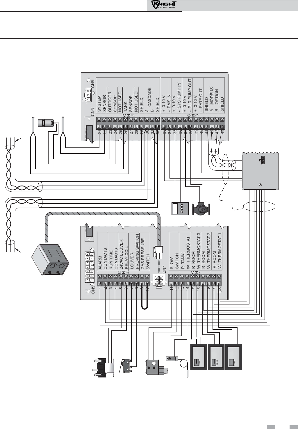
53
Installation & Operation Manual
8 Field wiring (continued)
LOUVER RELAY
FLOW SWITCH
TANK THERMOSTAT
ROOM THERMOSTAT 3
SYSTEM SUPPLY SENSOR
BUILDING
MANAGEMENT
SYSTEM
LOUVER
PROVING SWITCH
COM
NO
LOW WATER
CUTOFF
OUTDOOR SENSOR
TANK SENSOR
SHIELD SHIELD
TO
NEXT
BOILER
A
B
A
B
F
R
O
M
PREVIOUS
BOILER
ROOM THERMOSTAT 1
ROOM THERMOSTAT 2
NOTE:
CONNECTION BOARD SPLIT FOR
ILLUSTRATION PURPOSES
WIRE AS
NEEDED
SYSTEM PUMP
SPEED CONTROL
BOILER PUMP
A B
Figure 8-4 Low Voltage Field Wiring Connections

54
Installation & Operation Manual
9 Condensate disposal
Condensate drain
1. This boiler is a high efficiency appliance that produces
condensate.
2. The bottom of the boiler has a 1/2 inch pipe for
connection of a 1/2 inch PVC pipe (FIG. 9-1).
3. Slope condensate tubing down and away from the boiler
into a drain or condensate neutralizing filter. Condensate
from the Knight wall mount boiler will be slightly acidic
(typically with a pH from 3 to 5). Install a neutralizing
filter if required by local codes.
A Neutralizer Kit is available from the factory (Kit 3087).
4. Do not expose condensate line to freezing temperatures.
5. Use only plastic tubing or piping as a condensate drain
line (FIG. 9-1).
6. Leave the top of the tee assembly installed in the unit
open, this is needed as a vacuum break. The blocked drain
switch will shut the boiler down before any condensate
can flow out of the tee.
Use materials approved by the authority
having jurisdiction. In the absence of other
authority, PVC and CPVC pipe must comply
with ASTM D1785 or D2845. Cement and
primer must comply with ASME D2564 or
F493. For Canada use CSA or ULC certified
PVC or CPVC pipe, fittings, and cement.
7. A condensate removal pump is required if the boiler is
below the drain. When installing a condensate pump, select
one approved for use with condensing boilers and furnaces.
The pump should have an overflow switch to prevent
property damage from condensate spillage. The switch
should be wired in series with the blocked drain switch
inside the boiler (see FIG. 10-1 on page 56).
NOTICE
NOTICE To allow for proper drainage on large
horizontal runs, a second line vent may be
required and tubing size may need to increase
to 1 inch.
The condensate line must remain
unobstructed, allowing free flow of
condensate. If condensate is allowed to freeze
in the line or if the line is obstructed in any
other manner, condensate can exit from the
boiler tee, resulting in potential water damage
to property.
CONDENSATE TRAP
REMOVABLE CAP
FOR CLEANING TRAP
CONDENSATE DRAIN CONNECTION -
ROUTE TO FLOOR DRAIN OR
NEUTRALIZING FILTER USING:
1/2" PVC PIPE & FITTINGS or
1/2" CPVC PIPE & FITTINGS or
5/8" I.D. PLASTIC TUBING
(FIELD SUPPLIED)
Figure 9-1 Condensate Disposal
10 Start-up
Check/control water chemistry
Do not use petroleum-based cleaning or
sealing compounds in the boiler system.
Damage to elastomer seals and gaskets in
the system could occur, resulting in
substantial property damage.
Hardness less than 7 grains
1. Consult local water treatment companies for hard water
areas (above 7 grains hardness).
Chlorine concentration less than 200 ppm
1. Do not fill boiler or operate with water containing
chlorine in excess of 200 ppm.
2. Filling with chlorinated fresh water should be acceptable
since drinking water chlorine levels are much lower.
3. Do not use the boiler to directly heat swimming pool or
spa water.
Test/replace freeze protection fluid
1. For systems using freeze protection fluids, follow fluid
manufacturer’s instructions.
2. Freeze protection fluid must be replaced periodically due
to degradation of inhibitors over time. Follow all fluid
manufacturer’s instructions.
Freeze protection (when used)
1. Determine freeze protection fluid quantity using system
water content, following fluid manufacturer’s
instructions. Boiler water content is listed on page 6.
Remember to include expansion tank water content.
2. Local codes may require a backflow preventer or actual
disconnect from city water supply.
3. When using freeze protection fluid with automatic fill,
install a water meter to monitor water makeup. Freeze
protection fluid may leak before the water begins to leak,
causing concentration to drop, reducing the freeze
protection level.
4. The freeze protection set points may be lowered when
freeze protection fluid is used (see the Knight Wall
Mount Service Manual).
Fill and test water system
1. Fill system only after ensuring the water meets the
requirements of this manual.
2. Close manual and automatic air vents and boiler drain
valve.
3. Fill to correct system pressure. Correct pressure will vary
with each application.
a. The minimum cold water fill pressure for a
residential system is 12 psi.
b. Pressure will rise when boiler is turned on and
system water temperature increases.
Eliminate all system leaks. Continual fresh
makeup water will reduce boiler life.
Minerals can build up in the heat exchanger,
reducing heat transfer, overheating the heat
exchanger, and causing heat exchanger
failure.
Purge air from water system
1. Purge air from system:
a. Connect a hose to the purge valve (see purge/drain
valves, in piping diagrams on pages 38 through 45).
Route the hose to an area where water can drain and
be seen.
b. Close the boiler or system isolation valve between
the purge valve and fill connection to the system.
c. Close zone isolation valves.
d. Open quick-fill valve on cold water makeup line.
e. Open purge valve.
f. One zone at a time, open the isolation valves. Allow
water to run through the zone, pushing out the air.
Run until no noticeable air flow is present. Close the
zone isolation valves and proceed with the next zone.
Follow this procedure until all zones are purged.
g. Close the quick-fill water valve and purge valve and
remove the hose. Open all isolation valves. Watch
that system pressure rises to correct cold-fill
pressure.
h. After the system has operated for a while, eliminate
any residual air by using the manual air vents located
throughout the system.
i. If purge valves are not installed in the system, open
the manual air vents in the system one at a time,
beginning with the lowest floor. Close the vent when
water squirts out. Repeat with remaining vents.
2. Open automatic air vent (diaphragm-type or bladder-type
expansion tank systems only) one turn.
3. Open other vents:
a. Starting on the lowest floor, open air vents one at a
time until water squirts out.
b. Repeat with remaining vents.
4. Refill to correct pressure.
4. At initial fill and during boiler startup and testing, check
system thoroughly for any leaks. Repair all leaks before
proceeding further.
WARNING
CAUTION
55
Installation & Operation Manual
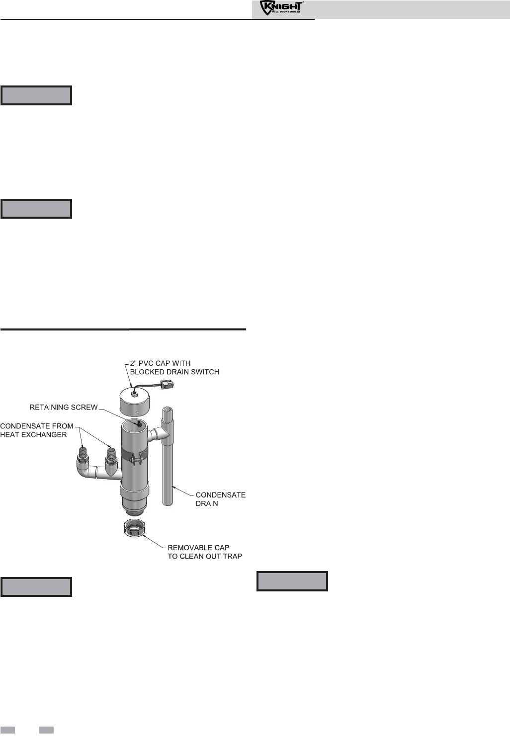
56
Installation & Operation Manual
10 Start-up
Check for gas leaks
Before starting the boiler, and during
initial operation, smell near the floor and
around the boiler for gas odorant or any
unusual odor. Remove the front access
panel and smell the interior of the boiler
enclosure. Do not proceed with startup if
there is any indication of a gas leak. Use
an approved leak detection solution.
Repair any leaks at once.
DO NOT adjust or attempt to measure gas
valve outlet pressure. The gas valve is
factory set for the correct outlet pressure.
This setting is suitable for natural gas and
propane, requiring no field adjustment.
Attempting to alter or measure the gas
valve outlet pressure could result in
damage to the valve, causing potential
severe personal injury, death, or
substantial property damage.
Propane boilers only – Your propane
supplier mixes an odorant with the
propane to make its presence detectable.
In some instances, the odorant can fade,
and the gas may no longer have an odor.
Before startup (and periodically
thereafter), have the propane supplier
verify the correct odorant level in the gas.
Check thermostat circuit(s)
1. Disconnect the two external wires connected to each of the
room thermostat terminals on the connection board.
2. Connect a voltmeter across these two incoming wires. Close
each thermostat, zone valve, and relay in the external circuit
one at a time and check the voltmeter reading across the
incoming wires.
3. There should NEVER be a voltage reading.
4. If a voltage does occur under any condition, check and
correct the external wiring. (This is a common problem
when using 3-wire zone valves.)
5. Once the external thermostat circuit wiring is checked and
corrected if necessary, reconnect the external thermostat
circuit wires to the connection board.
Inspect/fill condensate system
Inspect/check condensate lines and fittings
1. Inspect the condensate drain line, condensate PVC fittings
and condensate trap.
Fill condensate trap with water
1. Remove the bezel as depicted in FIG. 8-1 on page 50 of this
manual.
2. Remove the PVC cap retaining screw from the PVC cap
(FIG. 10-1).
3. Remove the 2 inch PVC cap with the switch located at the
top of the trap (FIG. 10-1).
4. Fill with fresh water until the water begins to pour out of the
drain.
5. Replace the cap. Press the cap onto the trap until the cap
makes contact with the drain.
6. Replace the retaining screw.
7. Reinstall bezel.
The condensate trap (FIG. 10-1) must be
filled with water during all times of boiler
operation to avoid flue gas emission from the
condensate drain line. Failure to fill the trap
could result in severe personal injury or
death.
Figure 10-1 Condensate Trap
WARNING
WARNING
WARNING WARNING
Clean/Inspect Trap Assembly
1. Remove the clean out cap on the bottom of the trap. Let the
condensate and any debris drain out.
2. Refill the trap according to the instructions above.
57
Installation & Operation Manual
10 Start-up (continued)
Final checks before starting the boiler
Read the Knight Wall Mount Service Manual to
familiarize yourself with SMART SYSTEM control
module operation. Read this manual, page 58 for proper
steps to start boiler.
Verify the boiler and system are full of water and all
system components are correctly set for operation.
Verify the preparation procedures of Section 10, pages 55
and 56 have been completed.
Fill the vent condensate trap with water (removing the
retaining screw in order to remove the 2 inch PVC cap
with the switch located at the top of the trap). Replace
the cap. Press the cap onto the trap until the cap makes
contact with the drain. Replace the retaining screw.
Verify electrical connections are correct and securely
attached.
Inspect vent piping and air piping for signs of
deterioration from corrosion, physical damage or
sagging. Verify air piping and vent piping are intact and
correctly installed per this manual.
Start the boiler
1. Read and follow the Operating instructions in FIG. 10-2,
page 58.
If boiler does not start correctly
1. Check for loose connections, blown fuse or service switch
off?
2. Is boiler water temperature above 200°F?
3. Is thermostat set below room temperature?
4. Is gas turned on at meter or boiler?
5. Is incoming gas pressure less than 4 inches w.c.?
If none of the above corrects the problem, refer to the
Troubleshooting Section of the Knight Wall Mount Service
Manual.
Check system and boiler
Check water piping
1. Check system piping for leaks. If found, shut down the
boiler and repair immediately. (See WARNINGS on
pages 55 and 56 (startup) regarding failure to repair
leaks.)
2. Vent any remaining air from the system using manual
vents. Air in the system will interfere with circulation and
cause heat distribution problems and noise.
Check vent piping and air piping
1. Check for gastight seal at every connection, seam of air
piping, and vent piping.
Venting system must be sealed gastight to
prevent flue gas spillage and carbon
monoxide emissions, which will result in
severe personal injury or death.
Check gas piping
1. Check around the boiler for gas odor following the
procedure on page 46 of this manual (connecting gas supply
piping).
If you discover evidence of any gas leak, shut
down the boiler at once. Find the leak source
with a bubble test and repair immediately.
Do not start the boiler again until corrected.
Failure to comply could result in severe
personal injury, death, or substantial
property damage.
Propane boilers – verify conversion
1. Verify propane conversion has been completed per the
Propane Conversion instructions.
DO NOT adjust or attempt to measure gas
valve outlet pressure. The gas valve is
factory-set for the correct outlet pressure.
This setting is suitable for natural gas and
propane, requiring no field adjustment.
Attempting to alter or measure the gas valve
outlet pressure could result in damage to the
valve, causing potential severe personal
injury, death, or substantial property
damage.
Check flame and combustion
1. Turn the main power off to the boiler.
2. Remove the flue temperature sensor from the flue pipe
connection. Note: Combustion measurements will be
made at this point.
3. Turn the main power on to the boiler.
WARNING
WARNING
WARNING
WARNING Knight wall mount boilers are typically
shipped ready to fire on natural gas. Check
boiler rating plate to determine which fuel
the boiler is set for. If set to natural gas, it
may be converted to LP by installing an
orifice (see page 13). In order to operate on
LP gas, an orifice MUST BE installed.
Failure to comply could result in severe
personal injury, death, or substantial
property damage.

10 Start-up
Figure 10-2 Operating Instructions
58
Installation & Operation Manual
59
Installation & Operation Manual
Please note that the brackets ([]) denote
screen status.
NOTICE
4. Place the boiler into the active position by pressing the
RIGHT SELECT [ON] key (FIG. 11-1, page 67).
5. Locate the pinhole button below the RESET button on the
display board (FIG. 11-1). Insert a thin wire (such as a
paper clip) into the hole and press the button once and
hold for 5 seconds to place the boiler into Service Mode.
In Service Mode the boiler will fire at ignition speed and
will then modulate up to full fire.
6. Insert the probe from a combustion analyzer into the hole
left by the removal of the flue temperature sensor.
7. Once the boiler has modulated up to full fire, measure the
combustion. The values should be in the range listed in
Table 10A below. The CO levels should be less than
150 ppm for a properly installed unit.
If the combustion is not within the specified range,
reference the Troubleshooting Section of the Knight Wall
Mount Service Manual for possible causes and corrective
actions.
10 Start-up (continued)
Check flame and combustion (continued) Set space heating operation
Determine controlling sensor
For space heating systems, the temperature control can be based
on one of three sensors; the inlet, outlet, or system supply
sensor. The SMART SYSTEM control is programmed at the
factory to control the temperature of the outlet sensor. The
control will automatically switch to the system supply sensor
once it is connected. If it is desired to base the temperature
control on the inlet sensor, the appropriate parameter must be
changed in the control. See the Knight Wall Mount Service
Manual for a detailed explanation of this procedure.
Verify space heat circulator mode
The Space Heating Mode controls both the system (primary)
pump (if connected), and the boiler (secondary) pump. When
the SMART SYSTEM control receives a space heating call for
heat, it turns on the system pump. If the boiler is not heating an
indirect DHW (Domestic Hot Water) tank, and the set point is
not met, it also turns on the boiler pump. After the space
heating call for heat ends, the system pump continues to run for
a short period of time. The system pump can be programmed
to run continuously, except during outdoor shutdown. If the
boiler pump was running, it continues to run for a short period
of time as well. These pump delays are factory set to 30 seconds.
If different delays are desired, the appropriate parameters in the
control must be changed. See the Knight Wall Mount Service
Manual for a detailed explanation of this procedure.
Adjust set point temperature
Table 10A Flue Products Chart
8. Once the combustion analysis is complete, test the
safety shutoff device by turning the manual shutoff
switch to the OFF position and ensuring that the boiler
shuts down and registers an alarm. Turn the manual
shutoff switch to the ON position, reset the control, and
return to Service Mode.
9. Turn the main power off to the boiler and replace the
flue temperature sensor into the flue pipe connection.
10. Place the boiler back into normal operation.
You must replace the flue gas temperature
sensor to prevent flue gas spillage into the
room. Failure to comply could result in
severe personal injury, death, or
substantial property damage.
WARNING
Natural Gas Propane
CO
2
O
2
CO
2
O
2
8.0% - 10% 3.0% - 6.5% 9.0% - 11% 4.1% - 6.9%
Please note that the brackets ([]) denote
screen status.
NOTICE
The NAVIGATION dial may be used during normal operation
to adjust the space heating and tank set point temperatures.
1. From the Status Screen press the NAVIGATION dial.
2. Turn the NAVIGATION dial counterclockwise to select the
appropriate set point.
3. Press the NAVIGATION dial to adjust the temperature.
4. Once the desired temperature is displayed, press the
RIGHT SELECT [SAVE] key.
5. If necessary repeat Steps 3 and 4 to make adjustments to
additional set points.
6. Press the RIGHT SELECT [HOME[ key to upload the
changes.
7. If the RIGHT SELECT [SAVE] key is not pressed, the
new settings will be discarded.
60
Installation & Operation Manual
10 Start-up
Set domestic hot water (DHW) operation
Verify DHW mode
There are two (2) modes of operation for DHW. In Normal
Mode, when a DHW demand begins, the control will start the
DHW pump, turn off the boiler pump (if running), and
modulate to bring the outlet temperature to the DHW boiler
set point. The maximum firing rate may be limited in this
mode if desired.
In Zone Mode it is assumed that the indirect DHW tank is
piped as a zone on the primary loop. When a DHW demand
begins, the control will turn on the DHW pump output, and
raise the system temperature set point to the DHW boiler set
point (if higher). The system pump and the boiler pump will
be turned on. In this mode, any low temperature zones (such
as radiant heating) may need additional controls to limit the
water temperature sent to those zones.
Set DHW target temperature
When in the DHW Mode, the control will modulate to
maintain the boiler outlet temperature or system supply
temperature to a set point. This set point is set at the factory
to 180°F. If a different set point is desired, the appropriate
parameter in the control must be changed. See the Knight
Wall Mount Service Manual for a detailed explanation of this
procedure.
Set maximum DHW fan speed
If the rated input of the indirect tank is less than the
maximum output of the boiler, change the maximum DHW
fan speed setting to limit the boiler output accordingly, see the
Knight Wall Mount Service Manual for a detailed explanation
of this procedure.
NOTICE The internal clock does not adjust for
Daylight Savings Time and therefore, will
require a manual adjustment.
7. Turn the NAVIGATION dial to adjust the minutes. Press
the NAVIGATION dial.
8. Turn the NAVIGATION dial to adjust the month. Press the
NAVIGATION dial.
9. Turn the NAVIGATION dial to adjust the date. Press the
NAVIGATION dial.
10. Turn the NAVIGATION dial to adjust the year. Press the
RIGHT SELECT [SAVE] key.
11. Press the RIGHT SELECT [HOME] key.
Please note that the brackets ([]) denote
screen status.
NOTICE
Configuration of the cascade
Please note that the brackets ([]) denote
screen status.
NOTICE
When installed in a Cascade system, the individual controls
must be programmed for cascade operation. This is
accomplished by accessing the control parameters.
Press the [MENU] key for at least five (5) seconds. Input the
Installer code as described in the Knight Wall Mount Service
Manual. Once the control parameters have been accessed, use
the NAVIGATION dial to select the Control Mode parameters.
Press the NAVIGATION dial to access these parameters.
Rotate the NAVIGATION dial to select the parameter Cascade
Address. Press the NAVIGATION dial to access this parameter.
Each appliance in the Cascade system must be programmed
with its own address. The boiler designated as the Leader will
have an address of 0. The remaining boilers in the Cascade will
be Members and have addresses from 1 - 7. Rotate the
NAVIGATION dial to select the appropriate address. Press the
RIGHT SELECT [SAVE] key. If installing the boilers in an
existing system, the new boilers should be programmed as the
Leader and/or the higher number addresses.
Press the RIGHT SELECT [HOME] key to upload the address
into the control. Repeat this procedure for all boilers in the
Cascade, designating the Leader control and the Member
controls.
Set clock
The SMART SYSTEM control has a built-in clock that it uses
for its night setback feature and for logging events. This clock
must be set when the boiler is installed, and anytime the
boiler has been powered off for more than 4 hours. Use the
following procedure to set the clock:
1. Press and hold the LEFT SELECT [MENU] key for at
least 5 seconds.
2. The display changes to read [PASSWORD],
with four (4) zeros below it.
3. Press the RIGHT SELECT [SAVE] key.
4. The display will then show a menu with the time and
date and temperature unit.
5. Press the NAVIGATION dial twice.
6. Turn the NAVIGATION dial to adjust the hours. Press
the NAVIGATION dial.

61
Installation & Operation Manual
11 Operating information
General
How the boiler operates
The Knight wall mount boiler uses an advanced stainless steel
heat exchanger and electronic control module that allows
fully condensing operation. The blower pulls in air and
pushes flue products out of the boiler through the heat
exchanger and flue piping. The control module regulates
blower speed to control the boiler firing rate. The gas valve
senses the amount of air flowing into the boiler and allows
only the right amount of gas to flow.
How the control module operates
The SMART SYSTEM control module receives inputs from
boiler sensors and external devices. The control module
activates and controls the blower and gas valve to regulate
heat input and switches the boiler, Domestic Hot Water
(DHW), and system pumps on and off as needed. The user
programs the module to meet system needs by adjusting
control parameters. These parameters set operating
temperatures and boiler operating modes. Boiler operation
can be based on boiler outlet water temperature, boiler inlet
water temperature, system temperature, a 0 - 10V signal, or
Modbus, depending on the parameter settings.
Control inputs and outputs
Room thermostat
There are three (3) thermostat connections available on this
control. These inputs tell the boiler to provide water for space
heating. Each thermostat connection has its own set point
and outdoor air reset curve. When multiple thermostats have
a call for heat the control will give priority to the demand
with the highest set point.
Example: Assume that both Room Thermostat 1 and Room
Thermostat 2 have a call for heat. RoomThermostat 1 has a
set point of 110°F. Room Thermostat 2 has a set point of
140°F. The boiler will regulate the system temperature to
140°F until Room Thermostat 2 has been satisfied. Once
Room Thermostat 2 has been satisified the boiler will provide
110°F water to the system.
0 - 10V input (set point or power)
The Knight wall mount boiler can be controlled by a Building
Management System (BMS) using a 0 - 10 vdc signal. The
control can be configured by the installer to use this signal to
either control set point or firing rate.
The Knight wall mount boiler can also be programmed to
accept a call for heat from a 0 - 10V signal, reference the
Knight Wall Mount Service Manual for a detailed explanation
of this procedure.
DHW priority
The SMART SYSTEM control allows the connection of a DHW
thermostat or tank sensor to the low voltage connection board.
When a tank sensor is connected, the DHW thermostat input is
ignored.
DHW / space heating (SH) cycling
If a DHW call for heat is received while a space heating call is in
progress and the DHW is in Normal Mode, the control will start
the DHW pump and shut the boiler pump off. The system
pump will remain on. If the space heating call is still active while
the DHW call is in operation, the control will wait for 30
minutes (time adjustable by installer) then it will switch back to
the space heating demand. There is a timer to switch from space
heating to DHW and a timer to switch from DHW to space
heating. The control will switch back and forth until one of the
heat demands end.
Programmable controlling sensor
The control module is programmed to use the outlet sensor as
the control sensor by default. If a system supply sensor is
connected, the control automatically uses it as the control
sensor. The control sensor can be changed by the installer to the
inlet sensor. If the inlet sensor is chosen as the controlling
sensor, it is recommended that the system supply sensor be
installed in order to provide the best control of the inlet
temperature.
Anti-cycling
After the burner turns off, the control will delay the next burner
cycle for a set time period (time is adjustable by the installer).
The time delay will be bypassed if the inlet water temperature
drops too far during the delay.
Boiler and system pump control
The boiler pump will run whenever the burner is firing, unless
the DHW is programmed for Normal Mode and the boiler is
heating the DHW tank. The boiler pump will run during Freeze
Protection Mode as well. It will continue to run for a short time
after the burner turns off or the Freeze Protection Mode ends.
The system pump will run whenever there is a space heating call
for heat, or the boiler goes into Freeze Protection Mode. It will
continue to run for a short time after the end of the heat
demand or the Freeze Protection Mode. The system pump can
be programmed to run continuously if desired. In either case, it
will not run during outdoor shutdown.
Temperature control
Modulation
The Knight wall mount boiler is capable of modulating its firing
rate from a minimum of 20% to a maximum of 100%. The
firing rate is dictated by the call for heat (i.e., space heating or
domestic hot water), the heating load, ramp delay (if enabled),
and various other temperature limitations.
CAUTION When multiple temperature loops are
used, thermostatic mixing valves are
required for the protection of any low
temperature loops.

62
Installation & Operation Manual
11 Operating information
Ramp delay
For systems with lower flow, the SMART SYSTEM can limit
the firing rate (when enabled) when a space heating call for
heat starts, or when switching from a DHW call for heat to a
space heating call for heat. There are six (6) limits that can be
programmed, as well as six (6) time intervals corresponding
to each limit. The sixth limit will also limit the firing rate for
the rest of the call for heat.
Gradient limiting
If during operation of the boiler the outlet water temperature
is rising too quickly, the control will reduce the firing rate to
its lowest setting.
Outdoor air reset
With the outdoor air sensor connected, the control module
will calculate the set points of the three (3) space heating
demands based on the programmed reset curves. The
installer can change the slope of the reset curves by several
adjustable parameters. The user can limit the maximum set
point for the system using the space heating set points.
Boost function
If outdoor air reset is active, and any space heating demand
has been active continuously for a set period of time (time
adjustable by installer) and there has been no DHW demands,
the control will increase the set point of that demand by a
fixed number of degrees (adjustable by installer). This
process will continue until the space heating demand ends,
the set point reaches the programmed set point or a
maximum of 20 increases has occurred. Once the system heat
demand is satisfied, the set point will revert to the value
determined by the reset curve.
Night setback
The controller may be programmed to reduce the space
heating and DHW set points during certain times each week.
Seven different start and stop times may be programmed for
the space heating setback and seven start and stop times for
the DHW setback.
Flame current support
To prevent nuisance shutdowns when the boiler is firing at
minimum rates, the control will increase the firing rate when
the flame signal drops too low.
Protection features
Outlet temperature, flue temperature, and
temperature rise limiting
The outlet temperature is monitored by the boiler outlet
temperature sensor. When the outlet temperature exceeds
185°F, the unit will reduce the fan speed. If the outlet water
temperature exceeds 195°F the control will shut the unit down
until it cools off.
The control module monitors the flue temperature by a sensor
located in the flue exhaust. If the flue temperature exceeds
215°F the control will reduce the maximum fan speed. If the
flue temperature exceeds 240°F the control will shut the unit
down. The unit will restart automatically once the flue
temperature drops 25°F and the minimum off time has expired.
The control monitors the temperature difference between the
inlet and the outlet sensor. If this difference exceeds 55°F the
control will reduce the maximum fan speed. If the temperature
difference exceeds 60°F the control will shut the unit down. The
unit will restart automatically once the temperature difference
has dropped below 55°F and the minimum off time has expired.
Freeze protection
DO NOT install the boiler in a room likely to freeze.
The following integral feature of the SMART SYSTEM control
module provides some protection for the boiler only -- not for
the system.
• The SMART SYSTEM control module provides
freeze-up protection as follows when the boiler
water temperature drops below 45°F:
• Below 45°F, the boiler and system pumps operate
constantly.
• Below 37°F, the boiler turns on.
• Boiler and pumps turn off if boiler water
temperature rises above 45°F.
• Lower temperatures may be programmed for
systems with anti-freeze solutions.
This feature of the SMART SYSTEM control
module does not eliminate the possibility of
freezing. The installation must still use
recognized design, installation and
maintenance practice to prevent freeze
potential for the boiler and system.
CAUTION
NOTICE When system return temperatures are
maintained below the dew point,
condensation will form on the inside of the
boiler jacket causing some internal sheet
metal components to rust.

63
Installation & Operation Manual
11 Operating information (continued)
Monitor external limits
Connections are provided on the connection board for
external limits such as flow switch, low water cutoff, gas
pressure switches, and a louver proving switch. The SMART
SYSTEM will shut off the burner and inhibit relighting
whenever any of these external limits open.
Run-time and alarm outputs
The boiler provides dry contacts for indicating when the
boiler is running, and when it is unable to operate.
Run-time and cycle counting
The control uses two timers to monitor the total hours of
burner operation. One timer monitors the time the boiler is
firing in the Space Heating Mode. The other timer monitors
the time the boiler is in the DHW Mode.
The control uses two (2) ignition counters to monitor the
amount of boiler cycles. The first counter counts all ignitions
of the control. The second counter counts only ignition
attempts that have failed.
Service reminder
The control can be programmed for service reminder
notification. This notification will become active when either
a set time frame has expired, or a set amount of running
hours or cycles has expired (all adjustable by the installer).
The display will show a Maintenance Required screen. The
service reminder notification can be reset or disabled by the
installer.
The time dependent feature has been disabled by the
manufacturer. To enable this feature change parameter K1 to
the desired time range, reference the Knight Wall Mount
Service Manual for details regarding parameters.
Error logging
The control will hold in memory the last 10 lockouts as well
as the last 10 blockings. The date and time of the occurrence
will be recorded as well. Only the 10 most current
occurrences of each will be held in memory.
Boiler temperature regulation
Operating temperature (target)
The SMART SYSTEM control module senses water
temperature and regulates boiler firing and firing rate to
achieve a target temperature. The target temperature can be
set between 32°F and 190°F.
• Target temperature is fixed when the outdoor
sensor is not installed.
• Target temperature is calculated as described in
this section under “Outdoor Reset Operation” and
“Target Temperature Boost” when the outdoor
sensor is connected.
High limit operations
The Knight wall mount is equipped with adjustable automatic
reset and manual reset high limits. The automatic reset high
limit has a maximum set point of 200°F and the manual reset
high limit has a maximum set point of 210°F.
When the outlet temperature exceeds 200°F, the automatic high
limit action occurs. The boiler shuts down until the outlet
water temperature cools below 190°F, and a 60 second timer has
expired. If the outlet temperature continues to increase, the
manual reset high limit action will occur at 210°F.
High limit test procedure
1. Turn ON the main power to the boiler by placing the
ON/OFF switch in the ON position.
2. If boiler status reads [SHUTDOWN] place the boiler into
the active position by pressing the RIGHT SELECT [ON]
key.
3. Locate the pinhole (SERVICE button) below the RESET
button on the display board. Insert a thin wire (such as a
paper clip) into the hole and press the button once, hold
for five (5) seconds to place the boiler into Service Mode.
In Service Mode the boiler will fire at ignition speed and
will then modulate up to full fire.
4. From the Status Screen, press the NAVIGATION dial to
access the Set Points Screen.
5. Press the LEFT SELECT [LIMITS] key.
6. Select the manual reset high limit (MRHL) by pressing the
NAVIGATION dial.
7. Decrease the set point of the MRHL below the outlet
temperature by turning the NAVIGATION dial
counterclockwise.
8. Press the RIGHT SELECT [SAVE] key.
9. Press the RIGHT SELECT [HOME] key.
10. The new parameters will upload to the control and the
MRHL will function causing boiler shutdown and
[LOCKOUT] to be displayed.
11. Press the RESET button to clear the lockout.
12. Repeat Steps 4, 5, and 6.
13. Set the MRHL to the appropriate set point by turning the
NAVIGATION dial clockwise.
14. Repeat Steps 8 and 9.
Low water cutoff protection
1. The SMART SYSTEM control module uses temperature
sensing of both supply and return areas of the heat
exchanger. If the flow rate is too low or the outlet
temperature too high, the control module modulates and
shuts the boiler down. This ensures boiler shutdown in the
event of low water or low flow conditions.
2. Some codes and jurisdiction may accept these integral
features of the control in lieu of requiring an additional
limit control or low water cutoff. Consult local jurisdiction
to determine. A low water cutoff is available from the
factory (WTR20009).
Please note that the brackets ([]) denote
screen status.
NOTICE
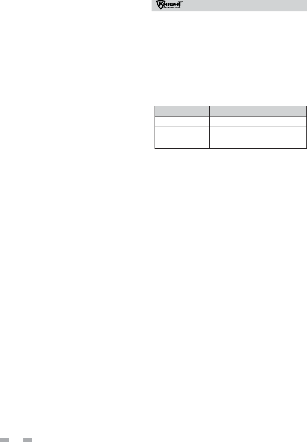
64
Installation & Operation Manual
11 Operating information
DHW, Night Setback, and Ramp Delay operation with
cascade
For normal mode DHW operation any boiler(s) in the Cascade
can be selected to provide heat for a DHW call. Select a boiler to
be designated as the DHW boiler. Connect the DHW thermostat
or sensor to the terminals on the Low Voltage Connection Board
marked for the corresponding device. When the boiler receives a
DHW call, the Leader control will take that boiler out of the
Cascade sequence. If another boiler is available, the Leader will
start it up to take its place.
The DHW boiler will adjust its set point to the programmed
DHW set point and will adjust its firing rate to maintain this.
Once the DHW call has been satisfied, the Leader control will
place that boiler back into the Cascade sequence.
Switching of the boiler between DHW operation and SH
operation when there is a call for both does not occur in Cascade
Mode.
When DHW is programmed for Zone Mode, connect the DHW
thermostat or tank sensor to the Leader boiler. When a DHW
call is received, the Leader will modulate the entire Cascade to
bring the system supply temperature up to the DHW boiler set
point (if higher).
Night Setback operation of the boilers within the Cascade is
available. Programming of the Night Setback will be done
through the Leader boiler. Refer to the Knight Wall Mount
Service manual for information regarding Night Setback.
Ramp Delay operation of the boilers as described in the Knight
Wall Mount Service Manual is not active when the boilers are
part of a Cascade system.
Sequence of the cascade
To equalize the run time of all boilers on the Cascade, the firing
sequence will automatically be changed at set intervals.
For the first 24 hours after initializing the Cascade, the sequence
will be changed every hour. After that the sequence will be
changed once every 24 hours. The switching on/off sequence
will be as follows:
DAY SWITCHING ON SEQUENCE
Day 1 L-M1-M2-M3-M4-M5-M6-M7
Day 1 + 1 hour M1-M2-M3-M4-M5-M6-M7-L
Day 1 + 2 hours M2-M3-M4-M5-M6-M7-L-M1
If a boiler is used to heat an indirect DHW tank, it will
automatically be given the lowest priority.
Cascade
When multiple boilers are installed, they can be wired
together in a cascade sequence. A maximum of eight boilers
can be controlled from a single control. In this application
one boiler would be designated as the Leader control and all
others would be designated as Member controls. If installing
the boilers in an existing system, the new boilers should be
programmed as the Leader and/or the higher number
addresses. The Leader control can be programmed to use
Lead/Lag or Efficiency Optimization control methods.
Once the Leader boiler receives a call for heat from a room
thermostat, BMS, or Modbus, the control will determine what
the set point will be. If outdoor air reset is desired, connect the
outdoor air sensor to the terminals on the Low Voltage
Connection Board on the Leader boiler. The set point will be
calculated based on the programmed reset curve parameters.
See the Knight Wall Mount Service Manual to program the
reset curve. If outdoor air reset is not desired, do not connect
the outdoor air sensor. A fixed temperature set point can be
programmed into the control. See page 59 of this manual to
program the set point.
If the water temperature at the system supply sensor is less
than the set point + the turn-off offset - the off-on
differential, then the control will initiate a call for heat on the
Cascade (see the Knight Wall Mount Service Manual for an
explanation of the offset and differential). The Leader will
energize the lead boiler on the Cascade. For a new startup this
will be the Leader boiler.
Outdoor reset operation, if used
Target temperature with outdoor reset
This feature improves the system’s efficiency as the outdoor
temperature warms up.
See the Knight Wall Mount Service Manual to change the
settings.
Reset curve
The reset curve looks at outdoor air temperature and adjusts
the set point.

65
Installation & Operation Manual
11 Operating information (continued)
Sequence of operation
OPERATION DISPLAY
1. Upon a call for heat, the gas pressure switch(es) must be closed.
2. Once the gas pressure switch(es) are closed, the control turns
on the appropriate pumps (system and boiler pumps for space
heating, DHW pump for DHW).
The flow switch and/or LWCO must close.
3. The control turns on power to the louver relay.
The louver proving switch, air pressure switch, and blocked
drain switch must close.
4. The control starts a 15 second prepurge cycle by initiating the
blower.
5. The control starts a 4 second trial for ignition by firing the spark
electrode and opening the gas valve.
6. If flame is not detected within 1 second after the sparking ends,
the control will perform a 10 second post-purge, then start
another prepurge cycle and try to light the burner again. The
control will perform a total of 4 attempts before locking out.
7. If flame is detected, it holds the firing rate steady for 5 seconds
to let the flame stabilize, then it begins to modulate the firing rate
based on a set point or some other command (such as a 0-10V
BMS signal).
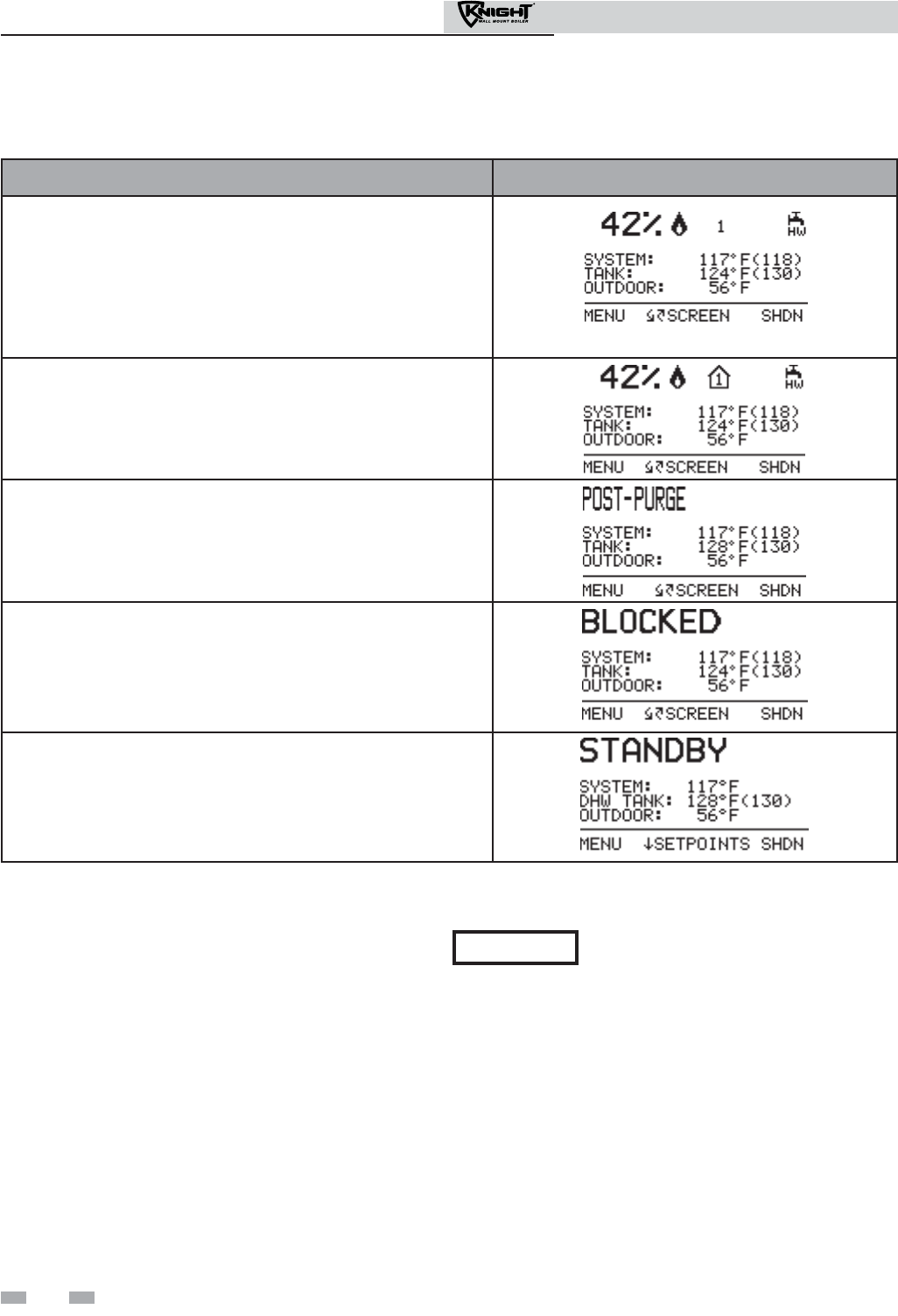
66
Installation & Operation Manual
11 Operating information
Sequence of operation (continued)
Access modes
User
The user can adjust space heating and tank target
temperatures by pressing the NAVIGATION dial when
“SETPOINTS” is flashing at the bottom of the display. The
date and time, and the temperature units can also be changed
(see page 60).
Installer
Most parameters are available only to the installer, accessible
by entering the installer password, see the Knight Wall Mount
Service Manual.
Saving parameters (reference the Parameter Table in
the Knight Wall Mount Service Manual)
To save parameters and exit programming:
Press the RIGHT SELECT [SAVE] key and then press the
RIGHT SELECT [HOME] key.
To enter a parameter and continue programming:
Press the RIGHT SELECT [SAVE] key 1 time to return to the
parameter listings; press again to return to the menu listings.
Remember to press the RIGHT SELECT [HOME] key when
finished programming in order to save the changes made.
See the Knight Wall Mount Service Manual for a detailed
description of parameters and access modes.
OPERATION DISPLAY
8. If the space heating call for heat is active, and the tank thermostat
or sensor starts a DHW call for heat, the boiler will switch to the
DHW mode. If programmed for normal DHW operation (not as a
zone), the DHW pump will turn on first, then the boiler pump will
turn off 2 seconds later.
This will divert the boiler’s outlet water from the heating system
and send it to the tank coil instead.
The control will then modulate to maintain the outlet temperature
9. If the boiler is not part of a Cascade, and both the space heating
and DHW calls for heat remain active long enough, the boiler will
switch back and forth between the two heating modes until one of
them is satisfied.
10. Once both calls for heat are satisfied, the control will turn off the
burner. The blower will continue to run during a 10 second
postpurge.
11. Any pumps that are running will continue to run for their
respective pump delay times before turning off, unless
programmed to remain on continuously.
A 60 second anti-cycle period will start, which will delay any new
call for heat until it times out.
12. In Standby, ready to start a new cycle.
Please note that the brackets ([]) denote
screen status.
NOTICE
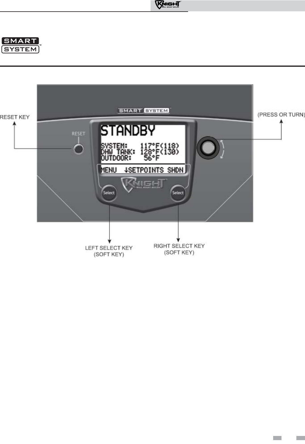
67
Installation & Operation Manual
Knight wall mount boiler control module
NAVIGATION DIAL
Figure 11-1 Control Panel
Use the control panel (FIG. 11-1) to set temperatures, operating conditions, and monitor boiler operation.
11 Operating information (continued)
The information on the bottom of the display shows the functions of the two SELECT keys (on either corner), and the
NAVIGATION dial (in the center):
MENU = Left SELECT Key
SETPOINTS = NAVIGATION Dial - Pressing Down
SHDN = Right SELECT Key
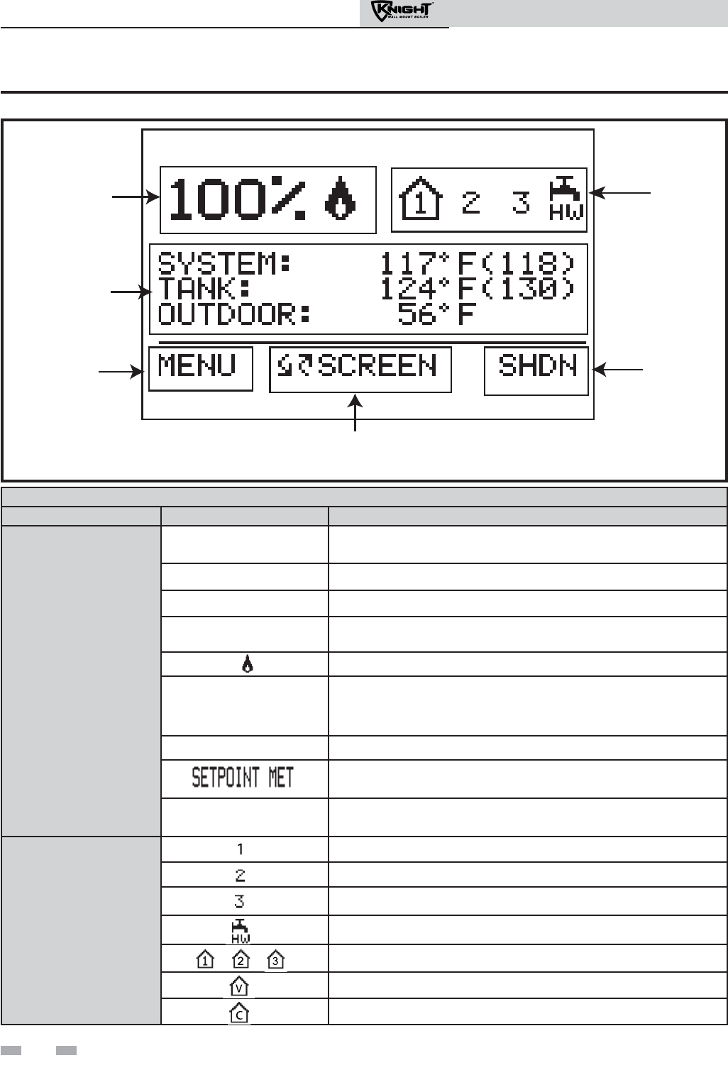
68
Installation & Operation Manual
11 Operating information
Status Display Screens
Section Display Description
A
(Boiler Status
Bar)
STANDBY The unit has not received a call for heat from a remote thermostat nor
has it received a call for heat from a DHW thermostat.
START The unit has begun a burn cycle and is checking all safety circuits.
PREPURGE The unit has initiated a 10 second purge period on a call for heat.
IGNITION The unit has begun a 4 second spark period to ignite the main burner.
The unit has fired and is running at the displayed percentage.
POSTPURGE
The call for heat has been satisfied and the unit runs the fan for an
additional 10 seconds to clear the combustion chamber and vent
system of residual flue products.
SHUTDOWN The unit has been placed in the OFF position.
The controlled temperature has exceeded its set point and its offset.
BLOCKED The unit has detected a condition that has temporarily interrupted
the current call for heat.
B
(Call for Heat
Indicators)
Room Thermostat 1 has a call for heat.
Room Thermostat 2 has a call for heat.
Room Thermostat 3 has a call for heat.
The tank thermostat or sensor has a call for heat.
Indicates which room thermostat demand shows priority.
The unit is being controlled by a 0 - 10V BMS signal.
The member unit is supplying heat while in Cascade Mode.
A
C
D
B
F
E
(BOILER
STATUS)
(OPERATIONAL
INFORMATION)
(LEFT SELECT
KEY)
(RIGHT SELECT KEY)
(NAVIGATION DIAL)
(CALL FOR
HEAT)
Figure 11-2 Status Display Screen
%

69
Installation & Operation Manual
Status Display Screens (cont’d)
Section Display Description
C
(Operational
Information)
SYSTEM: The temperature read by the system supply sensor (if connected).
TANK: The temperature read by the tank sensor (if connected).
OUTDOOR: The temperature read by the outdoor sensor (if connected).
INLET TEMP: The temperature read at the inlet to the heat exchanger.
OUTLET TEMP: The temperature read at the outlet of the heat exchanger.
DELTA T: The temperature difference between the inlet and the outlet of the
heat exchanger.
FLUE TEMP: The temperature read by the flue sensor.
FLAME CURRENT: The current measured by the flame sense circuit.
FAN SPEED: The speed of the combustion blower.
BOILER PUMP: The status of the boiler pump output.
SYSTEM PUMP: The status of the system pump output.
DHW PUMP: The status of the DHW pump output.
BMS VOLTAGE: The voltage received from a BMS system.
BLR PUMP OUTPUT: The speed signal sent to a variable speed boiler pump in percent.
SYS PUMP INPUT: The speed signal received from a variable speed system pump control.
RATE OUTPUT: A 0 - 10V signal indicating the firing rate of the boiler.
SH RUN HOURS: The total hours of operation in the Space Heating Mode.
SH CYCLES: The total burner cycles in the Space Heating Mode.
DHW RUN HOURS: The total hours of operation in the DHW Mode.
DHW CYCLES: The total burner cycles in the DHW Mode.
LAST 10 FAULTS NO:* The last 10 lockouts.
D
(LEFT SELECT
key function)
MENU Press and hold the LEFT SELECT key for 5 seconds to enter the Menu
Screen.
EXIT Press the LEFT SELECT key to exit the current screen or setting.
YES Press the LEFT SELECT key to confirm that the boiler needs to
shutdown.
LIMITS Press the LEFT SELECT key to enter the screen that allows you to
adjust the limit settings.
HOME Press the LEFT SELECT key to return to the Status Screen and upload
parameter changes.
11 Operating information (continued)
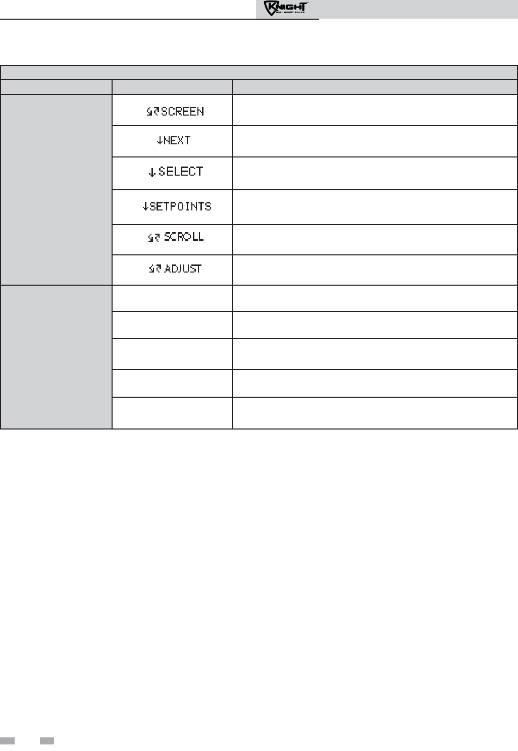
Installation & Operation Manual
70
11 Operating information
Status Display Screens (cont’d)
Section Display Description
E
(NAVIGATION
dial function)
Turning the NAVIGATION dial will select the next or previous Status
Screen.
Pressing the NAVIGATION dial will show the next fault, NSB (Night
Setback) trigger, or ramp delay setting.
Pressing the NAVIGATION dial will select the setting indicated by the
cursor.
Pressing the NAVIGATION dial will display the Set Points Screen.
Turning the NAVIGATION dial will move the cursor up or down.
Turning the NAVIGATION dial will increase or decrease the current
setting.
F
(RIGHT SELECT
key function)
SHDN Press the RIGHT SELECT key to turn the boiler OFF.
ON Press the RIGHT SELECT key to turn the boiler ON.
NO Press the RIGHT SELECT key to cancel the shutdown operation.
SAVE Press the RIGHT SELECT key to save the current change.
HOME Press the RIGHT SELECT key to return to the Status Screen and
upload parameter changes.
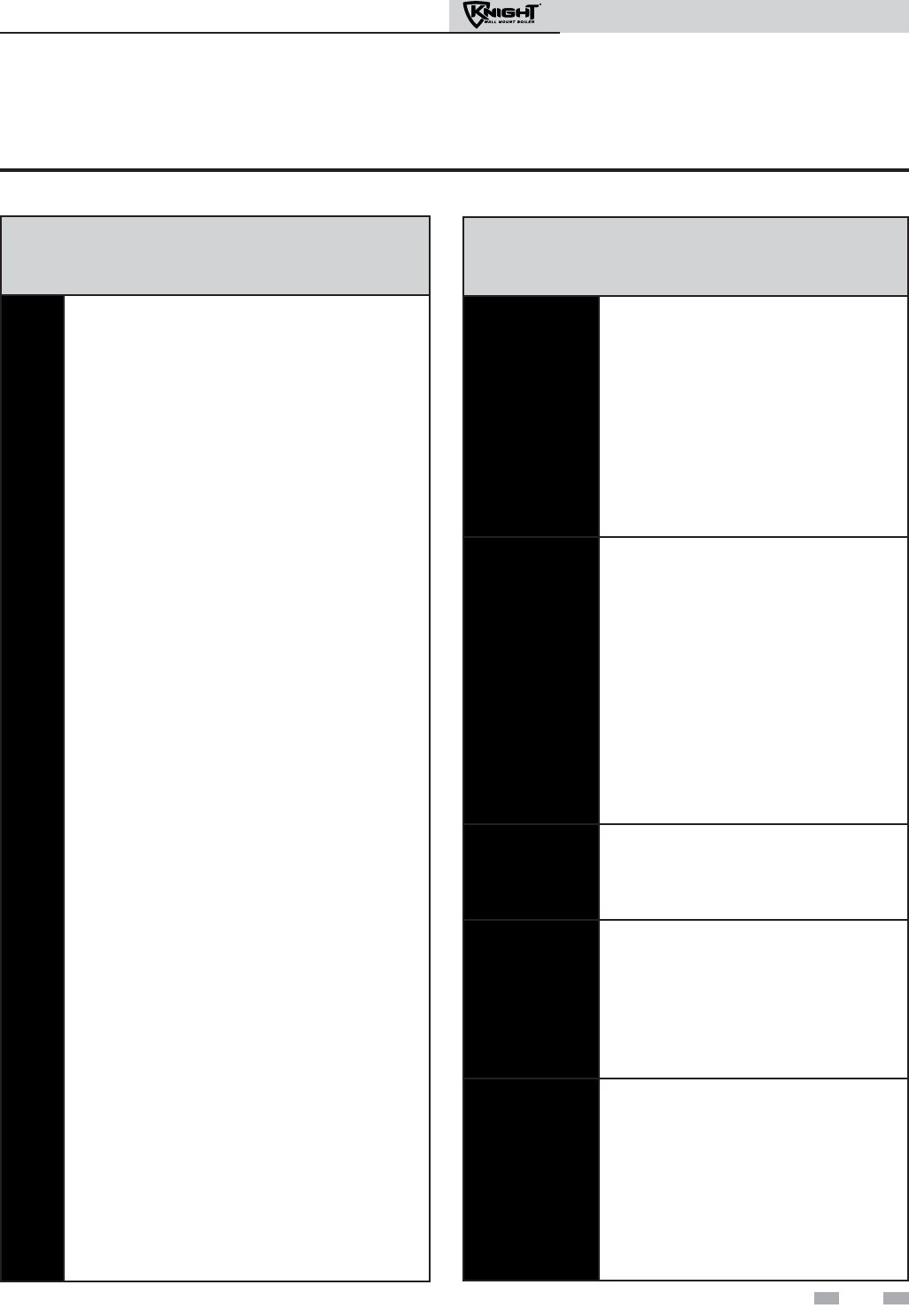
Installation & Operation Manual
71
Maintenance and annual startup
Table 12A Service and Maintenance Schedules
Service technician
(see the following pages for instructions)
General:
• Address reported problems
• Inspect interior; clean and vacuum if
necessary;
• Clean condensate trap and fill with fresh
water
• Check for leaks (water, gas, flue,
condensate)
• Verify flue and air lines in good condition
and sealed tight
• Check system water pressure/system
piping/expansion tank
• Check control settings
• Check ignition and flame sense
electrodes (sand off any deposits; clean
and reposition)
• Check wiring and connections
• Perform start-up checkout and
performance verification per Section 10
of this manual.
• Flame inspection (stable, uniform)
• Flame signal (at least 10 microamps at
high fire)
• Clean the heat exchanger if flue
temperature is more than 54°F above
return water temperature.
If combustion or performance
indicate need:
• Clean heat exchanger
• Remove and clean burner using
compressed air only
• Clean the blower wheel
ANNUAL START-UP
Owner maintenance
(see the Knight Wall Mount User’s Information
Manual for instructions)
Daily
• Check boiler area
• Check pressure/temperature
gauge
Monthly
• Check vent piping
• Check air piping
• Check air and vent termination
screens
• Check relief valve
• Check condensate drain system
• Check air vents
Periodically
• Test low water cutoff (if used)
• Reset button (low water cutoff)
Every
6 months
• Check boiler piping (gas and
water) for leaks
• Operate relief valve
End
of season
months
• Shut boiler down (unless boiler
used for domestic hot water)
12 Maintenance
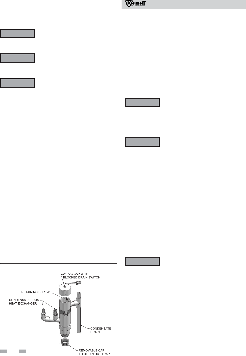
Installation & Operation Manual
12 Maintenance
Follow the Service and maintenance procedures given throughout this manual and in component literature
shipped with the boiler. Failure to perform the service and maintenance could result in damage to the boiler
or system. Failure to follow the directions in this manual and component literature could result in severe
personal injury, death, or substantial property damage.
The boiler should be inspected annually only by a qualified service technician. In addition, the maintenance
and care of the boiler designated in Table 12A and explained on the following pages must be performed to
assure maximum boiler efficiency and reliability. Failure to service and maintain the boiler and system could
result in equipment failure.
Electrical shock hazard – Turn off power to the boiler before any service operation on the boiler except as
noted otherwise in this instruction manual. Failure to turn off electrical power could result in electrical shock,
causing severe personal injury or death.
Address reported problems
1. Inspect any problems reported by the owner and correct
before proceeding.
Inspect boiler area
1. Verify that boiler area is free of any combustible
materials, gasoline and other flammable vapors and
liquids.
2. Verify that air intake area is free of any of the
contaminants listed in Section 1 of this manual. If any of
these are present in the boiler intake air vicinity, they
must be removed. If they cannot be removed, reinstall
the air and vent lines per this manual and the Knight Wall
Mount Service Manual.
Inspect boiler interior
1. Remove the front access cover and inspect the interior of
the boiler.
2. Vacuum any sediment from inside the boiler and
components. Remove any obstructions.
Clean condensate trap
1. Remove the clean out cap on the bottom of the trap. Let
the condensate and any debris drain out.
2. Fill with fresh water until the water begins to pour out of
the drain.
3. Replace the clean out cap and resume operation.
Eliminate all system or boiler leaks.
Continual fresh makeup water will reduce
boiler life. Minerals can build up in
sections, reducing heat transfer, overheating
heat exchanger, and causing heat exchanger
failure. Leaking water may also cause severe
property damage.
1. Inspect all water and gas piping and verify to be leak free.
2. Look for signs of leaking lines and correct any problems
found.
3. Check gas line using the procedure found in Section 7 -
Gas Connections.
Check all piping for leaks
The condensate trap must be filled with
water during all times of boiler operation to
avoid flue gas emission from the condensate
drain line. Failure to fill the trap could
result in severe personal injury or death.
WARNING
WARNING
WARNING
WARNING
WARNING
Figure 12-1 Condensate Trap
Flue vent system and air piping
1. Visually inspect the entire flue gas venting system and air
piping for blockage, deterioration or leakage. Repair any
joints that show signs of leakage. Verify that air inlet pipe is
connected and properly sealed.
2. Verify that boiler vent discharge and air intake are clean
and free of obstructions.
Failure to inspect for the above conditions
and have them repaired can result in severe
personal injury or death.
WARNING
Check water system
1. Verify all system components are correctly installed and
operational.
2. Check the cold fill pressure for the system. Verify it is
correct (must be a minimum of 12 psi).
3. Watch the system pressure as the boiler heats up (during
testing) to ensure pressure does not rise too high. Excessive
pressure rise indicates expansion tank sizing or
performance problem.
4. Inspect automatic air vents and air separators. Remove air
vent caps and briefly press push valve to flush vent. Replace
caps. Make sure vents do not leak. Replace any leaking
vents.
72
Installation & Operation Manual
Check expansion tank
1. Expansion tanks provide space for water to move in and
out as the heating system water expands due to
temperature increase or contracts as the water cools.
Tanks may be open, closed or diaphragm or bladder type.
See Section 6 - Hydronic Piping for suggested best
location of expansion tanks and air eliminators.
Check boiler relief valve
1. Inspect the relief valve and lift the lever to verify flow.
Before operating any relief valve, ensure that it is piped
with its discharge in a safe area to avoid severe scald
potential. Read Section 6 - Hydronic Piping before
proceeding further.
Safety relief valves should be re-inspected
AT LEAST ONCE EVERY THREE YEARS,
by a licensed plumbing contractor or
authorized inspection agency, to ensure
that the product has not been affected by
corrosive water conditions and to ensure
that the valve and discharge line have not
been altered or tampered with illegally.
Certain naturally occurring conditions
may corrode the valve or its components
over time, rendering the valve inoperative.
Such conditions are not detectable unless
the valve and its components are
physically removed and inspected. This
inspection must only be conducted by a
plumbing contractor or authorized
inspection agency – not by the owner.
Failure to re-inspect the boiler relief valve
as directed could result in unsafe pressure
buildup, which can result in severe
personal injury, death, or substantial
property damage.
Following installation, the valve lever must
be operated AT LEAST ONCE A YEAR to
ensure that waterways are clear. Certain
naturally occurring mineral deposits may
adhere to the valve, rendering it
inoperative. When manually operating
the lever, water will discharge and
precautions must be taken to avoid
contact with hot water and to avoid water
damage. Before operating lever, check to
see that a discharge line is connected to
this valve directing the flow of hot water
from the valve to a proper place of
disposal. Otherwise severe personal injury
may result. If no water flows, valve is
inoperative. Shut down the boiler until a
new relief valve has been installed.
2. After following the warning directions in this manual, if the
relief valve weeps or will not seat properly, replace the relief
valve. Ensure that the reason for relief valve weeping is the
valve and not over-pressurization of the system due to
expansion tank waterlogging or undersizing.
WARNING
WARNING
12 Maintenance (continued)
Inspect ignition and flame sense
electrodes
1. Remove the ignition and flame sense electrodes from the
boiler heat exchanger access cover.
2. Remove any deposits accumulated on the ignition/flame
sense electrode using sandpaper. If the electrodes cannot be
cleaned satisfactorily, replace with new ones.
3. Replace ignition/flame sense electrode, making sure gasket is
in good condition and correctly positioned.
Check ignition ground wiring
1. Inspect boiler ground wire from the heat exchanger access
cover to ground terminal strip.
2. Verify all wiring is in good condition and securely attached.
3. Check ground continuity of wiring using continuity meter.
4. Replace ground wires if ground continuity is not
satisfactory.
Check all boiler wiring
1. Inspect all boiler wiring, making sure wires are in good
condition and securely attached.
Check control settings
1. Set the SMART SYSTEM control module display to
Parameter Mode and check all settings. See Section 1 of the
Knight Wall Mount Service Manual. Adjust settings if
necessary. See Section 1 of the Knight Wall Mount Service
Manual for adjustment procedures.
2. Check settings of external limit controls (if any) and adjust
if necessary.
Perform start-up and checks
1. Start boiler and perform checks and tests specified in
Section 10 - Start-up.
2. Verify cold fill pressure is correct and that operating
pressure does not go too high.
Check burner flame
1. Inspect flame through observation window.
2. If the flame is unsatisfactory at either high fire or low fire,
turn off boiler and allow boiler to cool down. Remove the
burner and clean it thoroughly using a vacuum cleaner or
compressed air. Do not use compressed air to clean burner
if performed inside a building.
3. Remove the burner, reference FIG. 12-2 (page 74).
4. When replacing the burner, ensure gasket is in good
condition and positioned correctly (FIG. 12-2).
73
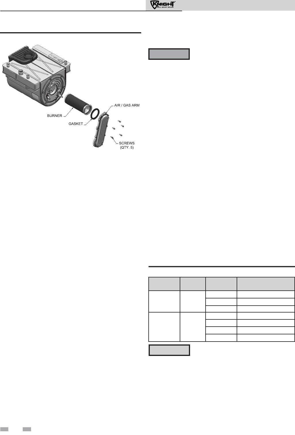
Installation & Operation Manual
74
12 Maintenance
Figure 12-2 Burner Assembly
Check flame signal
1. At high fire the flame signal shown on the display should
be at least 10 microamps.
2. A lower flame signal may indicate a fouled or damaged
flame sense electrode. If cleaning the flame sense
electrode does not improve, ground wiring is in good
condition, and ground continuity is satisfactory, replace
the flame sense electrode.
3. See Section 3 - Troubleshooting of the Knight Wall Mount
Service Manual for other procedures to deal with low
flame signal.
Review with owner
1. Review the Knight Wall Mount User’s Information
Manual with the owner.
2. Emphasize the need to perform the maintenance schedule
specified in the Knight Wall Mount User’s Information
Manual (and in this manual as well).
3. Remind the owner of the need to call a licensed contractor
should the boiler or system exhibit any unusual behavior.
4. Remind the owner to follow the proper shutdown
procedure and to schedule an annual start-up at the
beginning of the next heating season.
Oiled bearing circulators
1. The circulator shipped with the Knight wall mount boiler is
water-lubricated. No oiling is required.
2. Check other circulators in the system. Oil any circulators
requiring oil, following circulator manufacturer’s
instructions. Over-oiling will damage the circulator.
3. Replace the boiler front access cover.
The boiler contains ceramic fiber materials.
Use care when handling these materials per
instructions in the Service Manual. Failure to
comply could result in severe personal
injury.
WARNING
Cleaning boiler heat exchanger
For recommended materials; including brush, appropriate
extension(s), refractory cover, and detailed instructions see
Table 12B - Heat Exchanger Cleaning Kits.
1. Shut down boiler:
• Follow the “To Turn Off Gas to Appliance” instructions
for the boiler in Section 10 - Startup.
• Do not drain the boiler unless it will be exposed to
freezing temperatures. If using freeze prevention fluid
in system, do not drain.
2. Allow time for the boiler to cool to room temperature if it
has been firing.
3. Remove the nuts securing the heat exchanger access cover
to the heat exchanger and set aside.
5. Remove the condensate hose from the heat exchanger end.
Connect a field supplied 3/4" diameter hose to a drain pan.
Using field supplied means, cover the refractory in the back
of the combustion chamber of the heat exchanger.
6. Use a vacuum cleaner to remove any accumulation on the
boiler heating surfaces. Do not use any solvent.
7. Brush the heat exchanger while dry using a nylon bristle
brush. Caution: DO NOT use a metal brush. Re-vacuum
the heat exchanger.
8. Finish cleaning using a clean cloth dampened with warm
water. Rinse out debris with a low pressure water supply.
9. Allow the heat exchanger to thoroughly dry.
10. Remove the field supplied rear refractory cover from the
back of the combustion chamber of the heat exchanger and
reassemble.
11. Close isolation valves on piping to isolate boiler from
system. Attach a hose to the boiler drain and flush boiler
thoroughly with clean water by using purging valves to
allow water to flow through the water make-up line to the
boiler.
12. Perform start-up and check-out procedures in the Check
Flame and Combustion - Section 10 - Startup on pages 57
and 59 of this manual.
13. Replace the access cover and restore boiler to operation.
Table 12B Heat Exchanger Cleaning Kits
Model
Kit
Number
Part
Number
Component
Description
50 - 105 KIT30062
CTN20005 Rear Refractory Cover
MSC20083* Nylon 4" Wheel Brush*
MSC20085 1/4" x 12" Drill Extension
150 - 210 KIT30063
CTN20005 Rear Refractory Cover
MSC20083* Nylon 4" Wheel Brush*
MSC20084 3mm Allen Wrench
MSC20086 1/4" x 24" Drill Extension
* Do NOT use a metal brush. Only use the
kit provided brush or an equivalent
replacement nylon brush.
CAUTION
4. Remove the heat exchanger access cover, burner, and
gas/air arm assembly.
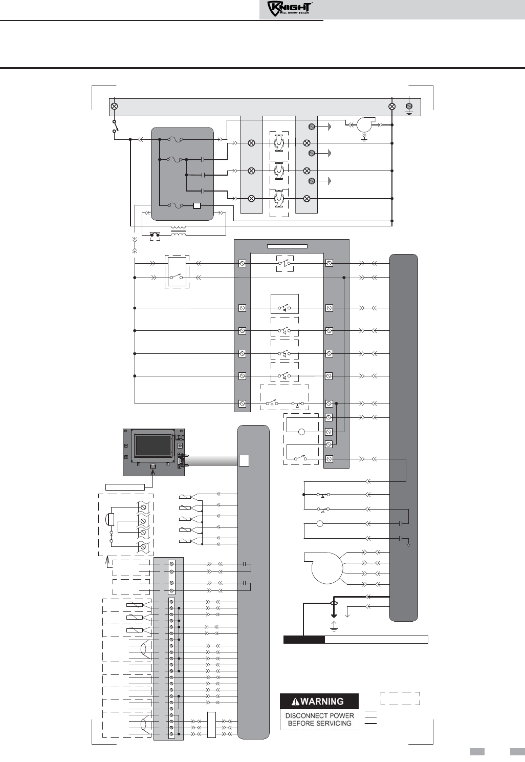
Installation & Operation Manual
75
13 Diagrams
BOX DEPICTS
OPTIONAL ITEMS
LADDER DIAGRAM
LBL20148 REV B
120 VAC
24 VAC
120VAC
TERMINAL STRIP
120V SUPPLY "L"
ON / OFF
SWITCH
X1-6 F2
NEUTRAL
FLOW
CN5-6
CN5-12
CN5-11
X4-2
X4-10
X4-11
INTEGRATED
CONTROL
LOW GAS
PRESSURE
SWITCH
HIGH GAS
PRESSURE
SWITCH
LOUVER
RELAY COIL
24VAC
LOUVER
PROVING SWITCH CN5-4 X4-4
X2-1
GAS VALVE
GAS VALVE
RELAY
X5-7
X5-16
X5-8
X5-15
1
2
4
5
3.15A
F1
5A
TR2
X1-7
FLAME ROD
SPARK
ROD
INTEGRATED CONTROL
GROUND
JUNCTION BOX
CAUTION HIGH VOLTAGE SPARK LEAD
BLOWER
CONNECTION
BOARD
INLET
SENSOR
OPERATING
SENSOR
FLUE
SENSOR
INTEGRATED
CONTROL
RUN-TIME
CONTACTS
RIBBON CABLE
X7
SYSTEM
SENSOR
TANK
SENSOR
OUTDOOR
SENSOR
0-10V
+
-
CASCADE A
B
SHIELD
SHIELD
13
6
2
1
SILENCING
SWITCH
ALARM
BELL
S6
S4
S5
BMS
CN6 X6
CN6 X6
CN6 X6
CN3-9 X4-9
CN3-6 X4-6
CN6 X6
CN6 X6
CN5-2 X4-6
CN5-9 X4-13
CN5-1 X4-7
CN5-8 X4-14
CN6 X6
CN6 X6
CN6 X6
HIGH LIMIT
SENSOR
FLUE
SENSOR
X5-4
X5-12
X5-5
X5-13
X5-14
X5-6
0-10V
+
-
SYS PUMP
IN
0-10V
+
-
BLR PUMP
OUT
0-10V
+
-
RATE
OUT
IN
MODBUS A
B
SHIELD
SHIELD
CN6 X6
CN6 X6
CN6 X6
CN6 X6
CN6 X6
CN8-1 X6-1
CN8-2 X6-2
CN8-3 X6-3
X4-1 X9-2
X4-2 X9-1
X4-3 X9-3
PC INTERFACE
S2
S1a
S1b
S3a
S3b
21
22
26
27
23
24
30
31
32
33
35
36
37
38
39
40
41
42
43
44
3
4
1
2
ALARM
CONTACTS
M
O
D
B
U
S
29
34
10
16
14
9
5
6
7
8
X2-2
NOTES:
1. Where possible, switches are shown without utilities (gas, water or
electricity) connected to the unit. As such, actual switch states may
vary from those shown on diagrams depending upon whether utilities
are connected or a fault condition is present.
2. See wiring diagram for additional notes.
CN5-3 X4-5
X1-1
12
BLOWER
SYSTEM PUMP
RELAY
DHW PUMP
RELAY
BOILER PUMP
RELAY
24V DC
SUPPLY
F3
.8A
X5-1
X5-9
3.5A
KB 801 ONLY
3
ROOM
THERMOSTAT 3
LWCO
CONNECTION BOARD
TANK
THERMOSTAT
13
15
CN5-13 X4-9
18
ROOM
THERMOSTAT 2
17
CN5-7 X4-1
20
ROOM
THERMOSTAT 1
19
11 12
SWITCH
CN7-1
CN7-3 CN7-2
CN7-4
CN5-10 X4-12
CN5-14 X4-8
CN5-5
X4-3
CONNECTION BOARD
X1-4
X1-3
X1-2
BOILER
PUMP "L"
DHW
PUMP "L"
SYSTEM
PUMP "L"
BOILER
PUMP
DHW
PUMP
SYSTEM
PUMP
BOILER
PUMP "N"
DHW
PUMP "N"
SYSTEM
PUMP "N"
TERMINAL
STRIP
TERMINAL
STRIP
GND
GND
GND
TERMINAL STRIP
120V SUPPLY "N"
LOW VOLTAGE
120 VAC
HIGH VOLTAGE
BLOCKED
DRAIN SWITCH
X5-2
X5-11
X5-10
AIR PRESSURE
SWITCH
Figure 13-1 Ladder Diagram
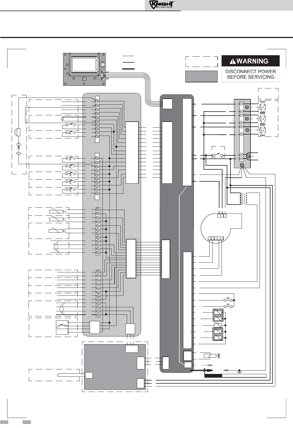
Installation & Operation Manual
X1-7
ON/OFF
SWITCH
123 4 5
G
R
RW
R
T
W
BK
Y
BL
BLOWER
-T
HIGH LIMIT SENSOR S1b
OPERATING SENSOR S1a
INLET SENSOR S2
FLUE SENSOR S3a
FLUE SENSOR S3b
INTEGRATED
CONTROL
BK
Y
GAS VALVE
@24VAC
SPARK
ROD
TRANSFORMER
TR2
G
HIGH VOLTAGE SPARK LEAD
CAUTION
FLAME SENSOR
ALARM
CONTACTS
RUN-TIME
CONTACTS
24 VAC LOUVER
RELAY COIL
LOUVER
PROVING SWITCH
GAS PRESSURE
SWITCH
FLOW
SWITCH
TANK
THERMOSTAT
ROOM TSTAT
ZONE CONTROL 3
ROOM TSTAT
ZONE CONTROL 2
ROOM TSTAT
ZONE CONTROL 1
11
12
13
14
15
16
17
18
19
20
SYSTEM
SENSOR
OUTDOOR
SENSOR
TANK
SENSOR
CASCADE A
B
SHIELD
SHIELD
0-10V
+
-
BMS
IN
0-10V
+
-
SYS PUMP
IN
0-10V
+
-
BLR PUMP
OUT
0-10V
+
-
RATE
OUT
MODBUS
OPTION
A
B
SHIELD
SHIELD
LOW
WATER
CUT-OFF
24 VAC
COM
P/BK
Y
W/R
1
2
3
4
5
6
7
8
9
10
21
22
23
24
25
26
27
28
29
30
31
32
33
34
35
36
37
38
39
40
41
42
43
44
CN7-1
CN7-2
CN7-3
CN7-4
CN5-1
CN5-8
CN5-2
CN5-9
CN5-3
CN5-10
CN5-11
CN5-4
CN5-5
CN5-14
CN5-12
CN5-6
CN5-13
CN5-7
X5-7
X5-16
X5-8
X5-15
X5-9
X5-1
X5-2
X5-10
X5-11
X5-4
X5-12
X5-6
X5-5
X5-13
X5-14
X2-2
X2-1
BK
Notes:
1. All wiring must be installed in accordance with: local, state, provincial and national code requirements per either N.E.C. in USA or C.S.A. in Canada.
2. If any original equipment wire as supplied with the appliance must be replaced, it must be replaced with wire having same wire gauge (AWG) and rated for a
minimum of 105°C. Exceptions: Replacement high vo ltage spark lead and ribbon cables must be purchased from the factory. Use of a non-approved spark lead
or ribbon cables can lead to operational problems which could result in non-repairable damage to the integrated controller or other components.
3. Actual connector block locations may vary from those shown on diagrams. Refer to actual components for proper connector block locations when using
diagrams to troubleshoot unit.
WIRING DIAGRAM
LBL20127 REV B
BOX DEPICTS
OPTIONAL ITEMS
X4-7
X4-14
X4-6
X4-13
X4-5
X4-12
X4-11
X4-4
X4-3
X4-8
X4-10
X4-2
X4-9
X4-1
BK
BK
BK
BK
BK
BK
BK
BK
BK
BK
BK
BK
BK
CONNECTION BOARD
CN6 X6
HIGH VOLTAGE
LOW VOLTAGE
120 VAC
X-7
BOX DEPICTS
DUAL SENSOR
SINGLE HOUSING
MODBUS BOARD
MTR-01
CN8-1
CN8-2
CN8-3
X6-3
X6-2
X6-1
X6-4
X9-1
X9-2
X9-3
X9-4
X4-1
X4-2
X4-3
X4-4
X5-1
X5-2
X1-1
X1-2
X1-3
BK
W
G
RBLG
-T
-T
-T
-T
SHIELD
GROUNDING
JUMPER
O
GY
G
R/BK
W/BK
GY
PR
1 2
G
3
BELL JUMPER
ALARM BELL
SILENCING SWITCH
JUNCTION
BOX
DHW
PUMP
BOILER
PUMP
SYSTEM
PUMP
BOX DEPICTS
OPTIONAL
ITEMS
G
G
G
L
GND
N
120V
SUPPLY
X1-3
X1-4
X1-2
X1-5
X1-6
X1-8
X1-1
BK
OR
W
W
W
BR
PR
W
L
N
L
N
L
N
L
N
KB ONLY
AIR PRESSURE
SWITCH
BLOCKED DRAIN
SWITCH
O
P
O/BK
Figure 13-2 Wiring Diagram
13 Diagrams
76

Installation & Operation Manual
Notes
77

Installation & Operation Manual
Notes
78

Installation & Operation Manual
Notes
79

Revision A (ECO #C05747) initial release. Reflects the new model
numbers for the Knight Wall Mount upgrade.
Revision B (ECO #C06188) reflects updates made to the ladder and
wiring diagrams (ECO #C06158).
Revision C (ECO #C06234) reflects changes made to the Service
Reminder feature.
WBII-I-O Rev C
8/10
