Locke Tr 30 Users Manual Trailer Sprayer Operator's
TR-30 TR-30_Operator
TR-30 to the manual faa9d711-8c13-49fc-86db-800974a4ec2a
2015-02-09
: Locke Locke-Tr-30-Users-Manual-575769 locke-tr-30-users-manual-575769 locke pdf
Open the PDF directly: View PDF ![]() .
.
Page Count: 36
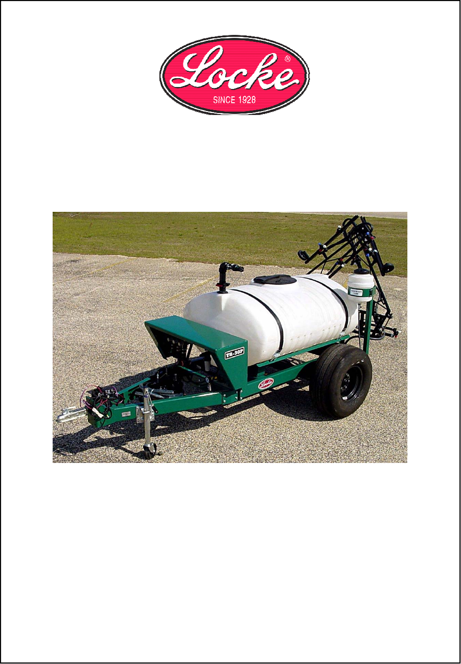
Trailer Sprayer
TR-30
Operators Manual
Locke Turf
307 Highway 52E, Opp, Alabama, 36467, (334) 493-1300

.CONGRATULATIONS
You have invested in the best implement of its type on the market today.
The care you give your Locke Turf implement will greatly determine your
satisfaction with its performance and its service life. We urge a careful
study of this manual to provide you with a thorough understanding of
you new implement before operating, as well as suggestions for opera-
tion and maintenance.
If your manual should become lost or destroyed, Locke Turf will be glad
to provide you with a new copy. Order from Locke Turf, 307 Highway
52E, Opp, Alabama 36467.
As and Authorized Locke Turf dealer, we stock genuine Locke Turf parts
which are manufactured with the same precision and skill as our original
equipment. Our trained service personnel are well informed on meth-
ods required to service Locke Turf equipment, and are ready and able to
help you.
Should you require additional information or assistance, please contact
us.
YOUR AUTHORIZED
LOCKE TURF DEALER
BECAUSE LOCKE TURF MAINTAINS AN ONGOING PROGRAM
OF PRODUCT IMPROVEMENT, WE RESERVE THE RIGHT TO MAKE
IMPROVEMENTS IN DESIGN OR CHANGES IN SPECIFICATIONS
WITHOUT INCURRING ANY OBLIGATION TO INSTALL THEM
ON UNITS PREVIOUSLY SOLD.
BECAUSE OF THE POSSIBILITY THAT SOME PHOTOGRAPHS
IN THIS MANUAL WERE TAKEN OF PROTOTYPE MODELS,
PRODUCTION MODELS MAY VARY IN SOME DETAIL. IN ADDITION,
SOME PHOTOGRAPHS MAY SHOW SHIELDS REMOVED FOR PUR
POSES OF CLARITY. NEVER OPERATE THIS IMPLEMENT WITHOUT
ALL SHIELDS IN PLACE.

TRAILER SPRAYER
Operator’s Manual
Table of Contents
SECTION
Warranty ………………………….2 4. Basic Operations ……….………...12
Federal Laws and Regulations ...3 Turf Application Guide …………….16
Dealer Preparation Check List …4 Field Adjustments ………………….19
1. Safety …………………………….5 General Operations ………………..21
Safety Decals …………………....7 5. Maintenance And Lubrication…..24
2. Introduction ……………………..8 Specifications……………………….26
3. Assembly and Set-up ………...10 Troubleshooting ……………………27
Torque Specifications ……………..34
RETAIL CUSTOMER’S RESPONSIBILITY
UNDER THE LOCKE TURF INC. WARRANTY
It is the Retail Customer and /or Operator’s responsibility to read the Operator’s Manual, to operate, lu-
bricate, maintain, and store the product in accordance with all instructions and safety procedures. Fail-
ure of the operator to read the Operator’s Manual is a misuse of this equipment.
It is the Retail Customer and/or Operator’s responsibility to inspect the product and to have any part(s)
repaired or replaced when continued operation would cause damage or excessive wear to other parts or
cause a safety hazard.
It is the Retail Customer’s responsibility to deliver the product to the authorized Locke Turf distributor
from whom he purchased it, for service or replacement of defective parts that are covered by warranty.
Repairs to be submitted for warranty consideration must be made within fort-five (45) days of failure.
It is the Retail Customer’s responsibility for any cost incurred by the Dealer for traveling to or hauling of
the product for the purpose of performing a warranty obligation or inspection.
UNDERSTAND SIGNAL WORDS
DANGER: Indicates an imminently WARNING: Indicates a potentially CAUTION: Indicates a potentially
Hazardous situation which, if not avoid- hazardous situation which, if not hazardous situation which, if not
Ed, will result in death or serious injury. Avoided, could result in death or avoided, may result in minor or
This signal word is to be limited to the serious injury. Moderate injury. It may also be
Most extreme situations. Used to alert against unsafe
Practices.

IMPORTANT FEDERAL LAWS AND REGULATIONS* CONCERNING
EMPLOYERS, EMPLOYEES AND OPERATIONS.
*(This section is intended to explain in broad terms the concept and effect of the following federal laws and regula-
tions. It is not intended as a legal interpretation of the laws and should not be considered as such.)
U.S. Public Law 91-596 (The Williams-Steiger Occupational and Health Act of 1970) OSHA
This Act Seeks:
“…to assure so far as possible every working man and woman in the nation safe and healthful
working conditions and to preserve our human resources…”
DUTIES
Sec. 5 (a) Each employer-
(1) shall furnish to each of his employees employment and a place of employment which are free
from recognized hazard that are causing or are likely to cause death or serious physical harm
to his employees;
(2) shall comply with occupational safety and health standards promulgated under this Act.
a. Each employee shall comply with occupational safety and health standards and all
rules, regulations and orders issued pursuant to this Act which are applicable to his
own actions and conduct.
OSHA Regulations
Current OSHA regulations state in part: “At the time of initial assignment and at least annually thereafter, the em-
ployer shall instruct every employee in the safe operation and servicing of all equipment with which the employee is
or will be involved.” These will include (but are not limited to) instructions to:
Keep all guards in place when the machine is in operations:
Permit no riders on equipment;
Stop engine, disconnect the power source and wait for all machine movement to stop before servicing,
adjusting, cleaning or unclogging the equipment, except where the machine must be running to be properly
serviced or maintained, in which case the employer shall instruct employees as to all steps and procedures
which are necessary to safely service or maintain the equipment.
Make sure everyone is clear of machinery before starting the engine, engaging power or operating the ma-
chine.
EMPLOYEE TRACTOR OPERATING INSTRUCTIONS:
1. Securely fasten your seat belt if the tractor has a ROPS 5. Watch where you are going especially at
row ends, on roads and around trees.
2. Where possible avoid operating the tractor near 6. Do not permit others to ride.
Ditches, embankments and holes.
7. Operate the tractor smoothly – jerky
3. Reduce speed when turning, crossing slopes and turns starts or stops
on rough, slick or muddy surfaces . 8. Hitch only to the drawbar and hitch
4. Stay off slopes too steep for safe operation . points recommended by tractor
manufacturers
9. When tractor is stopped, set brake
securely and use park lock if available
Child Labor Under 16 Years Old
Some regulations specify that no one under the age of 16 (sixteen) may operate power machinery. It is your re-
sponsibility to know what these regulations are in you own area or situation. (Refer to U.S. Dept, of Labor, Employ-
ment Standard Administration, Wage & Home Division, Child Labor Bulletin #102.)
3

DEALER PREPARATION CHECK LIST
Trailer Sprayer
BEFORE DELIVERING MACHINE- The following check list should be
completed. Use the Operator’s Manual
as a guide.
1. Assembly completed.
2. All Appropriate locations lubricated.
3. All shields in place and in good condition.
4. All fasteners torqued to specifications given in Torque Chart.
5. All decals in place and readable. (See decal page.)
6. Overall condition good (i.e. paint, welds)
7. Operator’s manual has been delivered to owner and he has been instructed on the
safe and proper use of the trailer sprayer.
Dealer’s Signature______________________________________________________
Purchaser’s Signature___________________________________________________
THIS CHECKLIST IS TO REMAIN IN OWNER’S MANUAL
It is the responsibility of the dealer to complete the procedures listed
above before delivery of this implement to the customer.
4

For your safety and to develop a better understanding of
your equipment, thoroughly read the Operator’s Sections
of this manual before operation.
Safety Notations
The safety alert symbol indications that there is a poten-
tial hazard to personal safety involved and extra safety
precautions must be taken. When you see this symbol,
be alert and care fully read the message that follows it.
In addition to design and configuration of equipment; haz-
ard awareness, concern, prudence and proper training of
personnel involved in the operation, transport, mainte-
nance and storage of equipment.
Watch for the following Safety Notation
throughout your Operator’s Manual:
Indicates an imminently hazardous situation which, if not
avoided, will result in death or serious injury. This signal
word is limited to the most extreme situations.
Indicates a potentially hazardous situation which, if not
avoided, could result in death or serious injury.
Indicates a potentially
hazardous situation which, if not avoided, may result in
minor or moderate injury. It may also be used to alert
against unsafe practices.
Safety Rules
These rules and instructions
must be reviewed at least annually
by all operators!
Most accidents are the result of negligence and careless-
ness, caused by failure of the operator to follow safety
precautions Even though your implement has been de-
signed with built-in safety features, the following precau-
tions are mandatory to prevent such accidents.
Make sure everyone that uses this machine has read the
Operator’s Manual and understands how to operate it
safely.
This Operator’s Manual is considered a part of the imple-
ment and should remain with it when loaded or sold.
Prior to Operation
1. Do not allow anyone to operate this machine who
has not been properly trained in its safe operation.
2. Never leave your fill hose attached to the sprayer
after filling the tank. Although your sprayer is
equipped with an anti-siphon device, if the vent holes
are covered or become plugged, siphoning can oc-
cur. Chemicals in the tank can siphon out of the tank
DANGER
WARNING
CAUTION
3. Use only water to calibrate and test the sprayer.
4. Always check the hand wash tank before taking the
sprayer to the field to be sure it is filled with clean
water.
5. Do not transport sprayer (by loading the vehicle and
sprayer on a trailer or other vehicle) when the tank is
filled with chemicals.
6. Agricultural chemicals can be dangerous. Always
select the correct chemical for the job. Improper us-
age of fertilizers, fungicides, herbicides, insecticides
and pesticides could cause injury to all living things.
7. Always real instructions supplied by the manufactur-
ers before opening chemical containers. Read and
follow instructions supplied by the chemical manufac-
turer carefully before each use.
8. Inform anyone who may come in contact with chemi-
cals or an implement with chemicals of any potential
hazards or safety precautions that should be ob-
served.
9. Store or dispose of all unused chemicals as specified
by the chemical manufacturer.
10. Always wear personal protective equipment. Refer to
“Personal Safety Equipment” section on page 3.
11. Always read chemical labels before using.
During Operation
1. Always be aware of any people that may be in the
area. Players, other maintenance personnel and
others may be on the course. It is the operator’s re-
sponsibility to operate the sprayer and vehicle in a
safety manner!
2. Never dismount from a moving vehicle.
3. Do not leave the vehicle unattended with the engine
running.
4. Do not exceed the calibrated spraying speed and
pressure when operating sprayer.
5. Spray only with acceptable wind conditions, below 5
mph. Carefully note outlying areas of the area to be
sprayed. Make sure wind drift of chemicals will not
affect any surrounding property, people or animals.
6. Be alert to traffic when crossing or operating near
roadways. Always maintain complete control of the
machine. Know your state and local laws concerning
highway safety and regulations. Comply with these
laws when driving the sprayer on any public thor-
oughfare.
7. Do not exceed 20 mph. Drive slowly over rough ter-
rain and use caution when traveling over hilly areas,
especially when the tank is full.
This sprayer can be dangerous and can cause bodily
harm if not properly used or guarded. Stay away from the
pump, drive shaft, electric clutch and drive belt when in
operation.
After Operation
1. Never wash the sprayer tank out within 100 feet of
any fresh water source or in a car wash. Dispose of
leftover chemical in the manner described on the
manufacturers’ label of the chemical used in the
sprayer. Rinse out the tank and spray the rinse water
on the last field that was sprayed.
WARNING
5
2. Do not ward contaminated clothing. Wash protec-
tive clothing and equipment with soap and water
after each use. Personal clothing worn during use
must be laundered separately from household arti-
cles. Clothing heavily contaminated with certain
crop protectant agents (read the label), must be
destroyed according to state and local regulations.
3. Wash your hands and face before eating when
working with chemicals. Shower as soon as you
have completed your spraying for the day.
During Maintenance
1. Keep all guards and shields in place. If removed for
repair or adjustment, replace them before operating
sprayer. If the sprayer is left with guards removed,
tag the unit so it is not used by others until it is re-
paired.
2. Before working on, servicing or making adjustments
on the sprayer, always disengage power, shut off
engine, make sure all moving parts have stopped
and all pressure in the system is relieved.
3. Do not work on the hoses, nozzles or plumbing
components (with the exception of the throttling
Valve) while the pump is running or the hoses are
pressurized. Shut off the pump and release sys-
tem pressure by turning the boom section
switches on before working on individual compo-
nents.
4. Do not grease or oil implement while it is in use.
5. After repairing or adjusting, make sure all tools
have been removed from the implement before
attempting to operate it.
6. Never use or store chemicals where children or
pets could be exposed.
Do not touch the sprayer components with your mouth
or lips. Never start a siphon hose by mouth. Chemical
ingestion can lead to illness and if untreated, death. If
the chemical is swallowed, carefully follow the chemi-
cal manufacturer’s recommendations and immediately
consult your doctor.
7. If you are exposed to a chemical in a way that could
affect your health, contact a physician immediately
with the chemical label or container in hand. Any de-
lay could cause serious illness or death.
WARNING
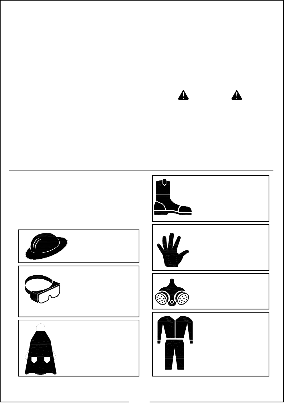
Personal Safety Equipment
Locke Turf advises all users of chemical pesticides or
herbicides to use the following personal safety equip-
ment. Always follow the chemical label instructions; your
safety and the effectively of the product depends upon
your actions.
Waterproof, wide-
brimmed hat.
Face shield, goggles or full
face respirator. Goggles
with side shields or a full
face respirator is required if
handling or applying dusts,
wettable powders or gran-
ules or if being exposed to
spray mist.
Waterproof apron.
Waterproof boots or foot
coverings.
Waterproof, unlined
gloves. Neoprene gloves
are recommended.
Cartridge-type respirator
approved for pesticide vapors
unless label specifies another
type of respirator.
Cloth coveralls/ outer clothing
changed daily; waterproof
items if there is a chance of
becoming wet with spray.
6
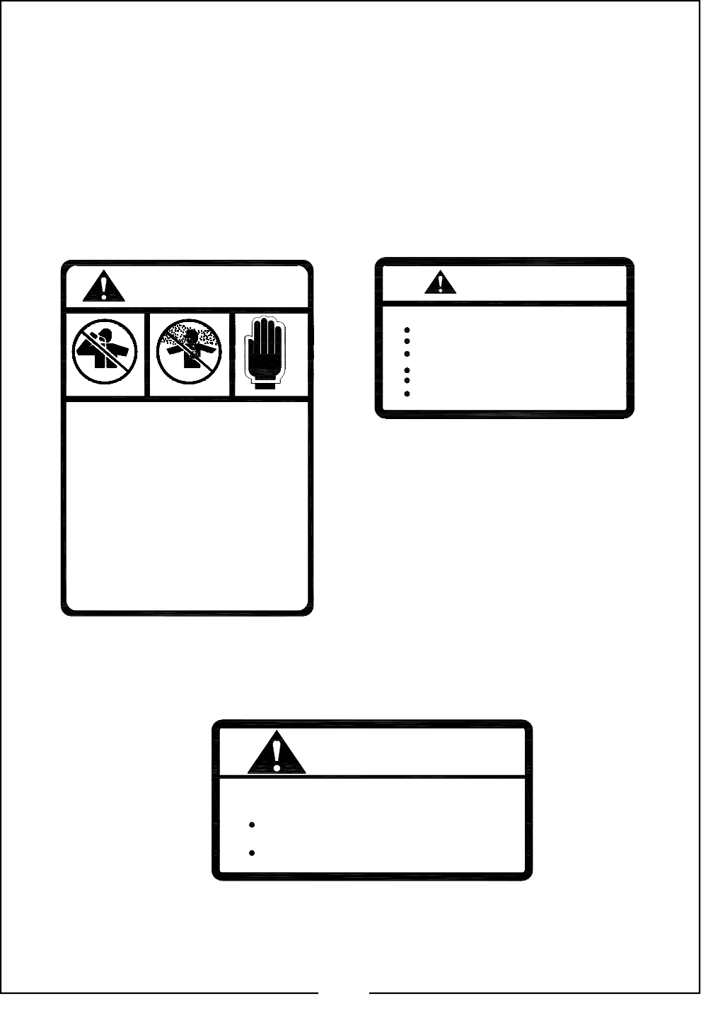
DANGER
POSSIBLE CHEMICAL HAZARD
Some chemcials can cause serious burns,
lung disease and even death.
To avoid:
READ AND FOLLOW CHEMICAL
MANUFACTURER'S INSTRUCTIONS.
Avoid contact with skin or eyes. Wear
proper protective equipment as required by
chemical manufacturer.
Avoid prolonged breathing of chemical fumes.
Wear respirator as required by chemical
manufacturer.
Seek medical assistance immediately if
accident occurs.
Maximum inflation pressure of tires is 30 psi.
Torque wheel bolts to 75 lb-ft.
Inflation or Torquing of Wheel Bolts:
To Avoid Injury or Machine Damage from Improper Tire
CAUTION
50022584
CAUTION
To Avoid Injury or Machine Damage
Read and understand owner's manual before operating sprayer.
Always read chemical labels BEFORE using.
Properly store chemical emptied from the tank or dispose of it by
the recommendations on chemical manufacturer's label.
Fasten appropriate fold pins when booms are folded.
Never allow riders.
Escaping hydraulic fluid can cause serious injury when equipped
with hydraulic components.
50022582
50022583
SAFETY DECALS
Your sprayer comes equipped with all safety de-
cals in place. They were designed to help you
safely operate your sprayer. Read and follow
their directions.
1. Keep safety decals clean and legible.
2. Replace all damaged or missing safety de-
cals. To order new safety decals go to you
Locke Turf Dealer.
3. General Decal Application: Replace theses
decals whenever they become worn or un-
readable. To install new safety decals:
a. Clean the area the decal is to be
placed.
b. Peel backing from the decal.
Press firmly onto surface being
careful not to cause air bubbles
under the decal.
7

Locke Turf welcomes you to the growing family of
new product owners. This implement has been de-
signed with care and built by skilled workers using
quality materials. Proper assembly, maintenance and
safe operating practices will help you get years of
satisfactory use from the machine.
Description of Unit
The Locke Turf TR-20 and TR-30 trailer sprayers are
tow behind units designed to be pulled by tractors or
large utility vehicles.
The sprayers are equipped with 200 or 300 gallon
polyethylene tanks.
A variety of booms are available to be used with the
trailer sprayers, either electric or manual lift controls,
wet or dry booms.
The TR models are equipped with Hy Pro PTO
pumps or optional engine drive Hy Pro pumps.
A selection of controls, either Tee Jet 744 economy
control or Tee Jet 844A deluxe controls are available
for these sprayers.
An electrically operated pressure control valve and
three solenoid-type directional control valves control
the flow of liquid between the tank and the three
boom sections. Excess system pressure returns liq-
uid to the tank for continuous agitation through the
bypass section of the solenoid valves (on standard
control units only). The liquid is constantly filtered
through an in-line Tee Jet filter.
Features Include:
• Heavy duty frame built from 14 gauge formed steel.
• Rugged, low profile 200 or 300 gallon polyethylene
tank.
• A two inch diameter anti-siphon fill kit with anti-spill
knife gate valve and fill tube extending to the bottom of
the tank to prevent foaming.
• Hy Pro pump with air blow-out valve to easily clean
plumbing lines and purge plumbing system for winter
storage.
• Tee Jet nozzle bodies.
• In-Line Tee Jet filter.
• Electric pressure regulating valve (Standard control
units only).
• Electrically-operated three-way solenoid directional
control valves with throttling valves to maintain con-
stant spraying pressure when one or two sections of
the boom are shut off (Standard control units only).
• Agitation line pressure gauge to monitor the fourport
hydraulic staniless steel agitator head.
• Control box with Master, Pressure Adjust and
Boom Section control switches, with mounting
bracket for attachment or Magnetic Gauge
Mount Assembly.
• A 3-1/2” glycerine-filled pressure gauge in 2
lb. Increments to 100 PSI and stainless steel
oil-filled Gauge Protector attaced on a Mag-
netic Gauge Mount.
Available Options Include:
• Deluxe Tee Jet Control and Monitor.
• Foam Marker Assembly
• Hose Reel (electric or manual)
• Walker Boom
• Hand Gun
Contact your Locke Turf dealer to purchase any of
these options.
Using this Manual
This Operator’s Section is designed to help
familiarize you with safety, assembly, opera-
tion, adjustments, trouble-shooting and main-
tenance. Read this manual and follow the
recommendations to help ensure safe and
efficient operation.
NOTE
The warranty sheet should be filled out by the
owner and dealer at the time of purchase.
After completion give the dealer the white
copy and send the pink copy to Locke Turf.
Keep your copy in the manual for use when
corresponding with the dealer.
To order a new Operator’s or Parts Manual
contact your authorized dealer or write to the
address listed below in the Owner Assistance
paragraph. Include the model and serial
numbers of your unit.
The information contained within this manual
was current at the time of printing. Some
parts may change slightly to assure you of
the best performance.
Terminology
“Right” or “Left” as used in this manual is deter-
mined by facing the direction the machine will
travel while in use unless otherwise stated.
NOTE: A special point of information related to its
preceding topic. Read and note this information
before continuing.
IMPORTANT: Information, related to its proceed-
ing topic, that the author feels would be of use.
8
Owner Assistance
If customer service or repair parts are required
contact your local Locke Turf dealer. They have
trained personnel, repair parts and the equipment
needed to service your implement.
These parts have been specially designed and
should only be replaced with genuine Locke Turf
parts.
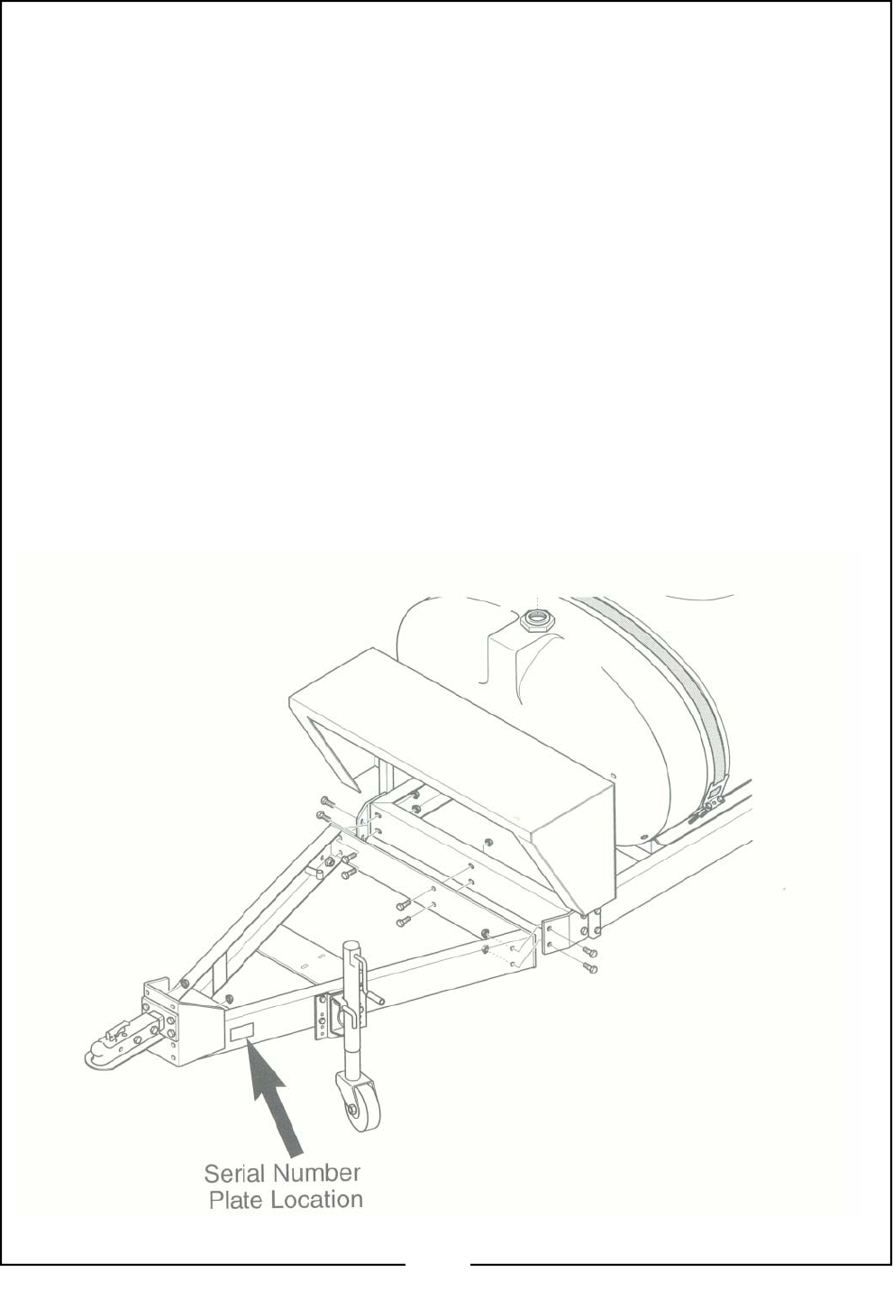
Serial Number Plate - Refer to the Figure below
for the location of your serial number plate. For
prompt service always use the serial number and
model number when ordering parts from you
Locke Turf dealer. Be sure to include your serial
number and model number in correspondence
also.
Your dealer wants you to be satisfied with your
new machine. If for any reason you are not
Satisfied with the service received, the following
actions are suggested:
1. First, discuss the matter with your dealership
service manager. Make sure he is aware of
any problems you may have and that they have
had the opportunity to assist you.
2. If you are still not satisfied, seek out the owner
or General Manager or the dealership and ex-
plain the problem and request assistance.
3. For further assistance beyond that provided by
your dealer, you may contact:
Locke Turf Inc. - Customer Service
307 Highway 52E
Opp, AL 36467
www.locketurf.com
9
Assembling The Sprayer
Tools and Equipment Needed:
• Hoist or Floor jack rated for at least 2,000 lbs.
• SAE wrenches
• A helper to assist in moving the sprayer
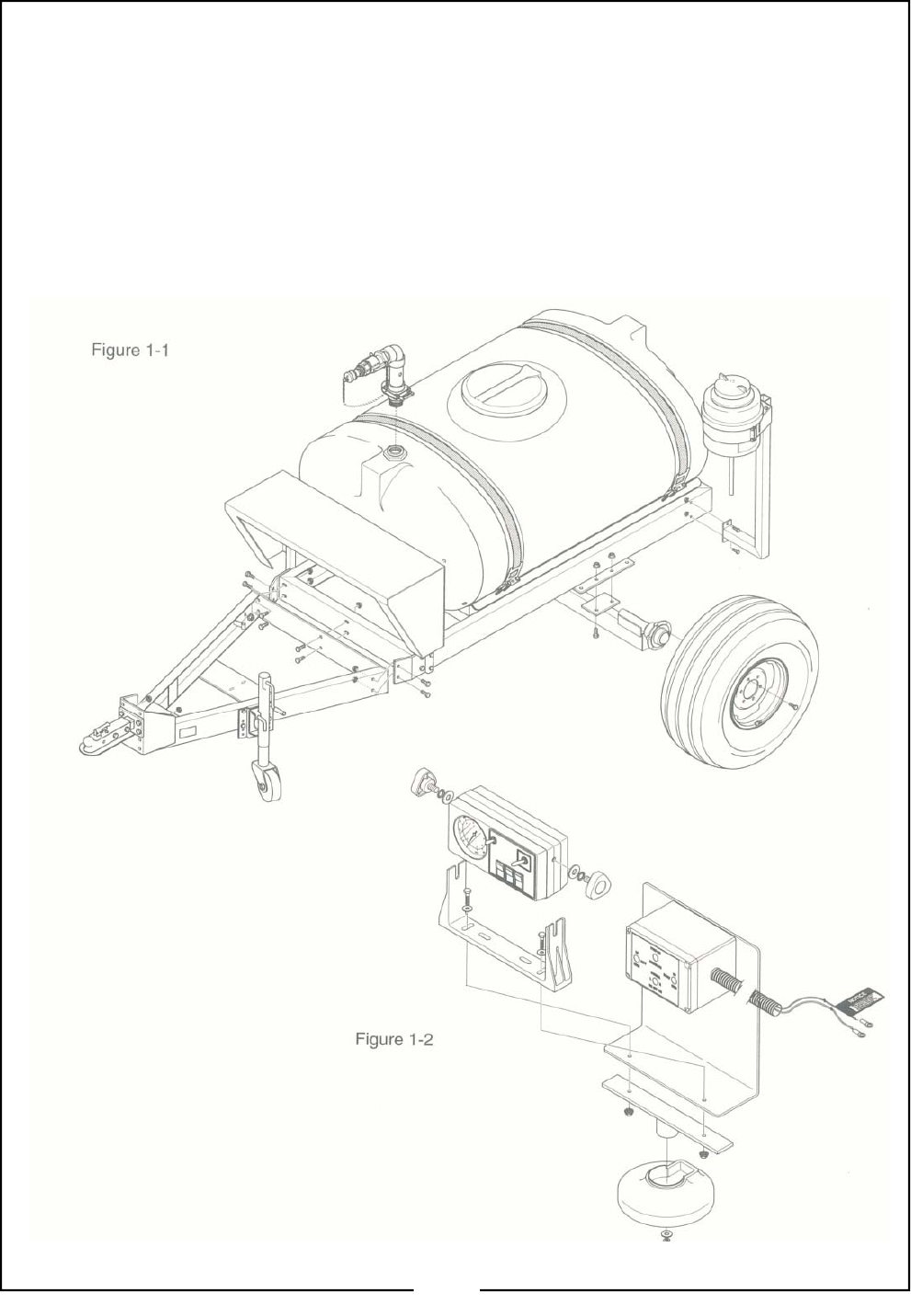
Refer to Figure 1-1
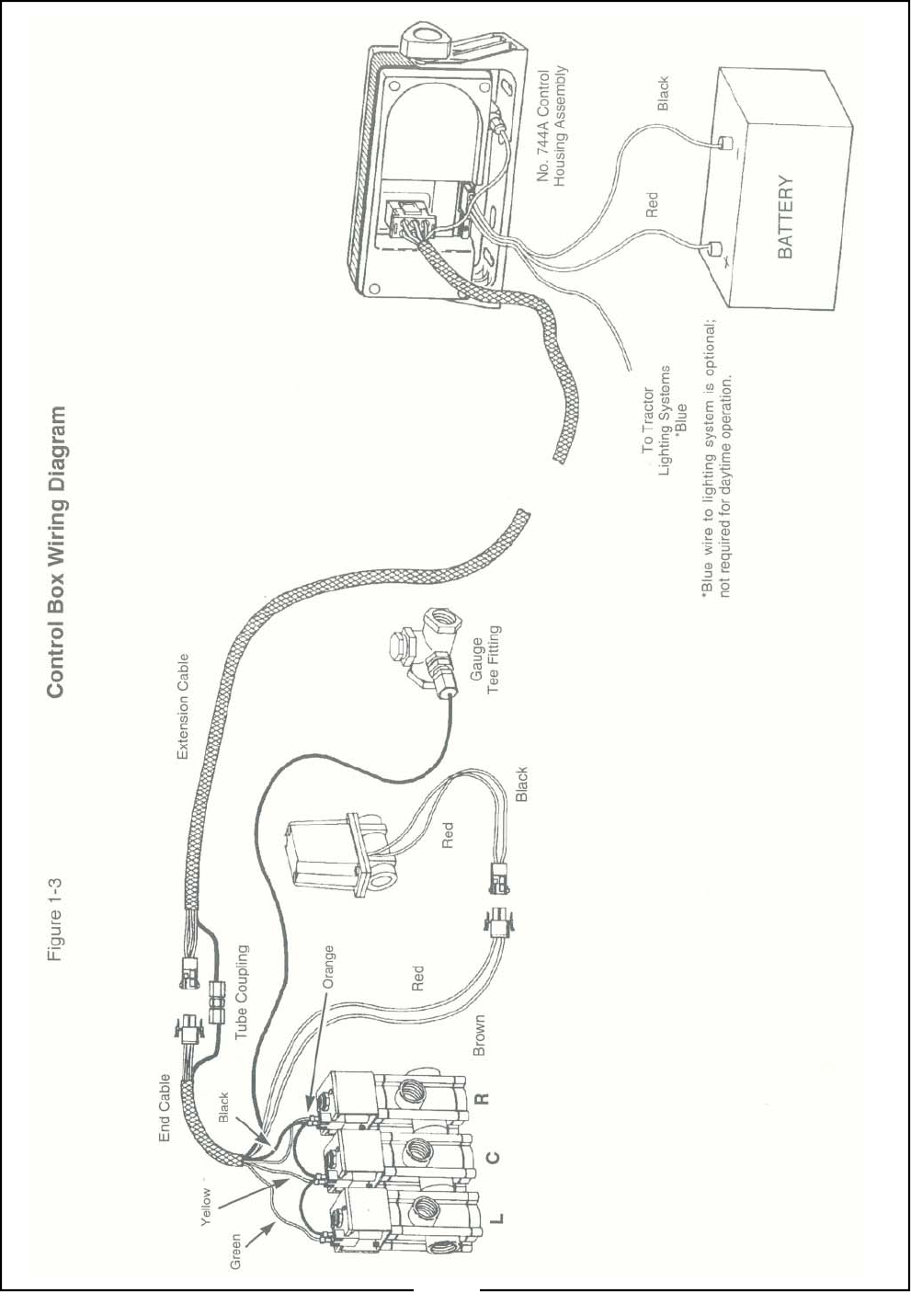
Mounting the Control Box
Refer to Figure 1-2
The magnet mount should be attached to a con-
venient location on the towing vehicle (fender,
hood, etc.).
10
11

This section describes the workings of the
sprayer components and provides guidelines on
their use. More detailed information can be found
in Preparing the Sprayer in “General Operations”
section starting on page 21.
Basic Sprayer Operating Guidelines
1. Make sure to read the label on the chemical
compound that is to be applied; it is the law!
2. Consider how the chemical will be stored and
how you will dispose of the chemical, accord-
ing to the chemical label. Planning in ad-
vance may save much trouble later.
3. When calibrating, filling the tank or working
around chemicals, wear protective clothing
that covers the body. Refer to Personal
Safety Equipment in the “Important Safety
Information” section. Have soap and clean
water available to wash any exposed areas.
Never open a container with your bare hands.
4. Fill the hand wash tank on the sprayer with
fresh water before handling any chemicals.
5. Fill the sprayer and mix the chemicals at an
appropriate mixing site.
6. By law, you must repeat the rinsing of the
chemical container three times. The con-
tainer should then be punctured to prevent
future use. An alternative is to jet-rinse or
pressure rinse the container.
IMPORTANT: Any washing or mixing that pro-
duces contaminated liquid should take place at
an appropriate mixing site. Chemically contami-
nated liquid should be captured in a holding tank
for proper disposal and not be allowed to run off
where it may contaminate fresh water sources.
7. Check the condition of hoses and connections
frequently. Release system pressure before
working on the sprayer by shutting off the pump
and flipping the individual boom section switches
on the control box. Always wear rubber gloves
when making repairs or adjustments to the
spraying components.
8. If your sprayer boom is equipped with a level-
float pin, remove it before operating the
sprayer. The boom will float over the con-
tours of the ground more effectively and mini-
mize stress on the boom.
9. Apply spray when the wind is 5 mph or less.
Minimize drift by using nozzle tips with the
largest practical openings and by operating
the sprayer boom at the lowest practical pres-
sure.
10. Drive at the same speed you used in your
calibration. Refer to Miles Per Hour Calibra-
tion in the Tee Jet manual.
11. If possible work crosswise to the wind, start-
ing from the downwind side of the area to be
sprayed. Do this so you won’t ever be head-
ing directly into chemical fumes.
12. As you operate the sprayer, be aware of all
things that may be affected by the chemicals,
such as adjoining property, houses, gardens,
people, etc. Do not operate the sprayer if
damage can occur.
13. When you are finished spraying, empty the
tank and flush the sprayer with water, includ-
ing the pump, the nozzles and the bypass line
form the solenoids. Properly store the chemi-
cal emptied form the tank or dispose of it by
the recommendations on its label.
14. When turning at the end of a run, make sure
that the boom will not overlap on areas previ-
ously sprayed.
Plumbing Operations
(Manual Control System Only)
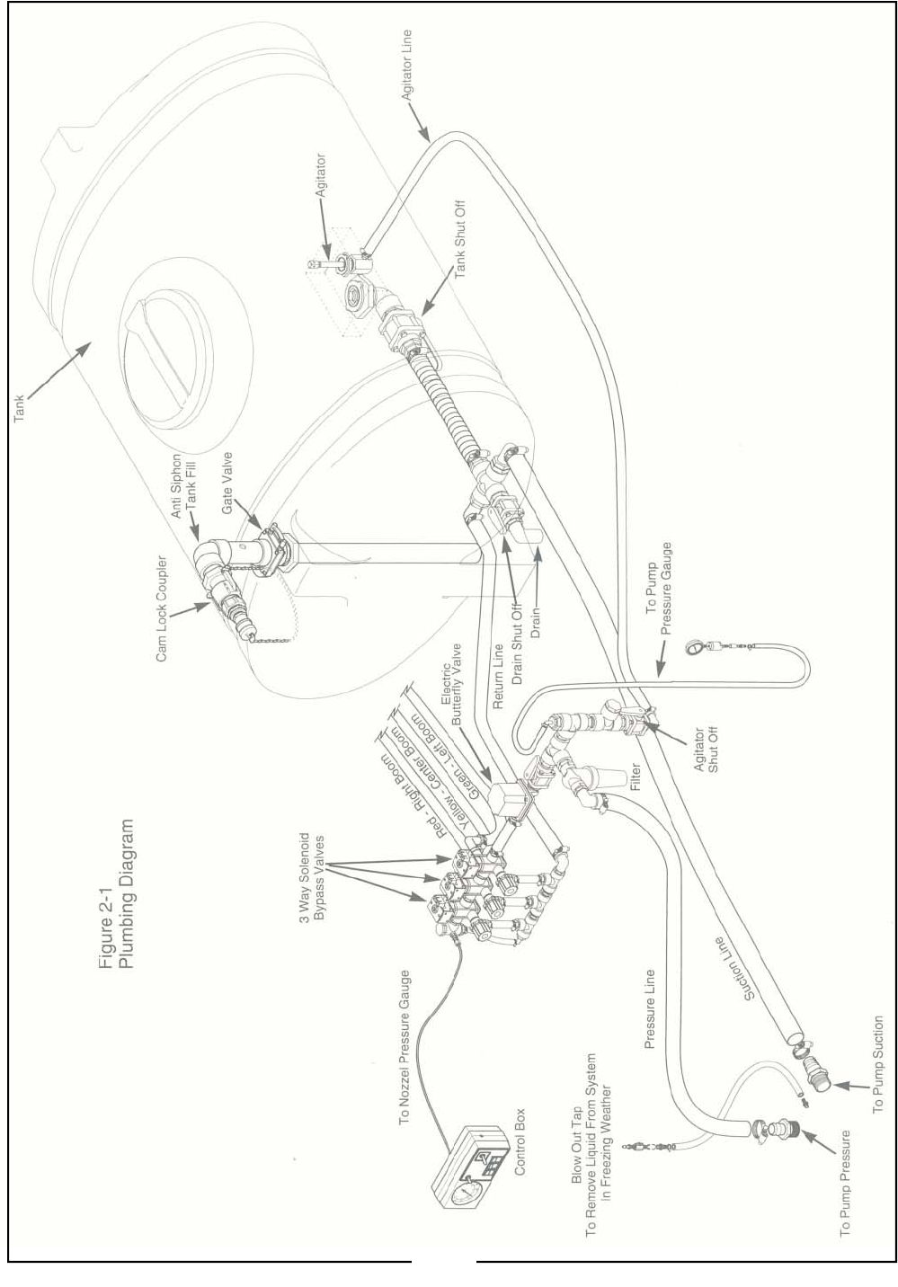
Refer to Figure 2-1
An understanding of how the sprayer works will
help you to operate your Locke Turf Sprayer.
The basic operation of the sprayer as follows.
12
13

Fluid is drawn out of the tank sump and passes through
the pump. From the pump the solution passes through
the filter and filters out or grinds up most undissolved
chemical and solid particles. The fluid then passes
through the agitation valve and returns to the tank via
the agitator head or proceeds through the pressure con-
trol valves. If the fluid passes through the electric pres-
sure control valve, it proceeds to the 3-way solenoid
valves. If a solenoid is on, its coil is energized and the
connected valve is open. The fluid will pass through the
valve and travel to the specific boom section (left, center
or right) and is delivered to the area to be treated
through the sprayer boom nozzles. If the particular
switch is off, the solenoid is de-energized and the con-
nected valve is closed. In this case, the fluid travels
through the bypass and returns to the tank sump.
You can monitor the nozzle pressure gauge and adjust
the pressure to the booms by adjusting the pressure
adjust switch on the control box. The pressure adjust
switch operates the electric pressure control valve. To
set this valve, see Pre-setting the Pressure Control
Valves in the next column. This will decrease the
amount of flow to the electric pressure control valve and
reduce its sensitivity.
There are tank shut off valves at every tank outlet so
that if there is a leak, the contents of the tank can be
secured and a chemical spill avoided. These valves
(except for the tank drain valve) need to be fully open
when the sprayer is in use.
Pressure Adjustment Valves
NOTE:
Refer to Sprayer Parts Manual if you need help identify-
ing specific sprayer components.
The plumbing system is equipped with two pressure ad-
justment valves, electric and manual. The two valves
work together and understanding how they work is im-
portant to proper sprayer operation.
The Electric Pressure Control Valve
The primary purpose of this valve is to allow the opera-
tor to adjust boom pressure while spraying. The electric
pressure control is a 12 volt DC operated butterfly type
valve. It is controlled by the pressure adjust switch on
the control box. When the switch is engaged, electric
current travels through the gearbox controlling the valve,
saucing the butterfly mechanism to move. The valve
has no stops and can be adjusted a full 360 degrees.
The Manual Pressure Control Valve
The main purpose of this valve is to reduce the sensitiv-
ity of the electric pressure control valve so that small
movements of the butterfly valve mechanism won’t re-
sult in uncontrollable changes in boom pressure. With-
out the manual pressure control valve, toggling the pres-
sure adjust switch just a few times will result in fast pres-
sure changes in boom pressure, adversely affecting ap-
plication rates. This manual valve restricts the amount
of flow to the electric pressure control valve, thus nar-
rowing the range of pressure.
Pre-setting the Pressure Control Valves
(Manual Control Systems Only)
NOTE:
Before beginning this procedure make sure your throt-
tling valves are adjusted. Refer to Calibrating the Throt-
tling Valves in General Operations starting on page 19.
To adjust the pressure control valves and achieve a de-
sirable adjustment range at the control box, do the fol-
lowing:
1. Open the electric control valve (by toggling the pres-
sure switch at the control box) until the valve is fully
open.
2. Turn the boom sections off so that the liquid is trav-
eling through the bypass line and retuning to the
tank.
3. Operate the pump at the same RPM you would
when spraying.
4. Adjust the manual pressure control valve until the
boom pressure as indicated on the pressure gauge
by the control box is 10 to 20 PSI greater than the
maximum application pressure.
The Drive Pump
IMPORTANT: The Hy Pro pump supplied with your
sprayer is not designed for use with every application.
Materials containing solvents, paints or solutions con-
taining abrasives will damage the pump. If you are un-
sure of you chemicals, consult your dealer for suitability
of your application.
IMPORTANT: Always use the MASTER on/off switch to
control spraying action.
PTO Drives
The pump on this type of drive is powered by the vehi-
cle’s PTO shaft. The PTO shaft is manually operated by
the driver and once engaged, turns regardless of gear
selection. The speed of the PTO is directly proportional
to engine speed. Higher engine RPM results in higher
PTO (and pump) speed, and ultimately higher system
pressure (70 lbs. PSI Max.) for spraying.
14

IMPORTANT: Do not use the vehicle’s PTO con-
trol to control the spraying action. When the PTO
is disengaged, the pump stops turning, all agitation
of the chemical stops and the sprayer loses system
pressure. Use the MASTER on/off switch of the
boom section switches to control spraying action.
Anti-Siphon Fill Assembly
When filling the sprayer tank, make sure that
the anti-siphon holes in the side of the tube are
clear and open. The anti-siphon device pre-
vents the solution in the tank form infiltrating
into the fresh water source and contaminating
it.
Your Locke Turf Sprayer tank is filled form the top
through a standard 1-1/2” Cam-Lock coupler.
1. To fill the tank, first make sure that the tank
drain valve is closed. Open the knife valve on
the fill assembly.
2. Connect the fresh water hose to the quick-fill
camlock coupler. Make sure that the anti-
siphon holes in the side of the fill tube are clear
and open.
3. Turn the water on and fill the tank. Do not al-
low the tank to fill unattended. When filled,
close the knife valve.
4. Clean and fill the handwash tank.
Adding Chemicals to the Tank
Read the manufacturer’s label carefully before
handling chemicals. When you add the chemi-
cal, follow the manufacturer’s instructions for
mixing the spray solution in order to achieve
the desired application rate. Always wear re-
quired protective gear.
1. Before adding chemical to the tank, make sure
the tank is at least half full and the pump and
agitation is operating. The concentrate should
not be poured into an empty tank as this may
clog the tank lines.
2. Keep the spray solution form skin. Wear pro-
tective clothing and goggles. If the solution
comes in contact with the body, wash off the
contaminated area with soap and water.
3. Keep chemical containers low when pouring.
4. Do not smoke while handling chemicals.
CAUTION
CAUTION
Using Handwash Tank
In the event when an accident occurs and chemical
comes in contact with skin or eyes, use the hand-
wash tank to flush away the chemical.
1. Open the tank valve and use the hose to direct
the clean water on all contaminated areas.
Wash all areas of skin that have been contami-
nated with soap and water. To flush out eyes,
point the hose and water stream upward while
lowering eyes into the stream of following wa-
ter.
2. Close the tank valve and refill the handwash
tank with fresh water.
3. Clean and refill the handwash tank with fresh
water each time the sprayer is used. Always
keep the handwash tank clean.
Operating the Filter
Your Locke Turf Sprayer is equipped with a Tee Jet
filter to remove unwanted particles from the systme
and prevent the hoses from becoming clogged.
The filter is located on the output line of the cen-
trifugal pump and before the manual pressure ad-
justment valve. It filters the chemical solution being
sprayed.
To clean out the filter, unscrew the main body, re-
move screen and clean with clear water.
Driving and Parking
1. Park your sprayer in an area where you will not
hit power lines, building, etc. when boom is
folded.
Contact with electrical power lines can cause
death by electrocution.
2. Don’t leave the sprayer unattended in an area
where unauthorized persons may tamper with
the sprayer, tank contents or controls.
3. Don’t leave a filled sprayer without tagging or
somehow identifying the contents. Someone
may mistake a chemical filled tank for water
and spray unwanted areas. Do not exceed 20
mph transporting your sprayer.
4. Do not unnecessarily transport sprayer while
filled with chemical mixture.
DANGER
15
Sprayer Pre-Calibrations
General Guidelines
1. Wear proper protective clothing as described
in Personal Safety Equipment on page 6.
2. From the chemical manufacturer’s label and
field conditions, select a spray application
rate and an operating speed.
IMPORTANT: If you are unsure of what you are
doing, get help. Do not guess at application
rates.
3. Be familiar with the type of chemical you are
using. Completely read the label before start-
ing.
4. Have all equipment ready before starting your
sprayer calibrations.
5. Make sure all spray parts are free from for-
eign material and are functioning properly.
Carefully inspect nozzles and internal parts
for wear, defects, proper size and type.
6. Fill spray tanks with water at least one quar-
ter full and preferably half full.
7. Use only water to calibrate the sprayer.
8. With the sprayer stationary, operate the pump
at the desired spraying pressure. Check for
leaks and improper spray patterns form the
nozzles.
9. Read the following pages to determine which
method of calibration you will use and have a
clear understanding of how the procedure
works.
Calibration Method #1
This method calibrates the sprayer and checks to
make sure the nozzles are within specifications.
1. Select your desired application rate, either in
gallons per thousand square feet of gallons
per acre.
2. Select you desired gear or RPM setting for an
appropriate spraying speed. Calibrate your
speed to verify that the vehicle’s speedome-
ter is accurate. Refer to the following table
Miles Per Hour Calibration for calibration val-
ues.
3. Find your desired application rate in the noz-
zle chars in this section. For every applica-
tion rate there will be at least two nozzles that
will yield the desired application. For applica-
tions that require foliar coverage, select the
nozzle requiring higher pressure. This will
produce smaller droplets. For less drift of for
chemicals that need to reach the oil surface,
select the nozzle that uses lower pressure.
This will produce larger droplets. For exam-
ple, your desired gallon per thousand square
feet (GPT) application rate is 1.01 GPT at 4
miles per hour. Refer to the nozzle charts in
the Tee Jet manual.
4. Find the ounces per minute output for the
nozzles to be used. See the Tee Jet manual.
5. With water in the sprayer, catch the nozzle
output at the desired pressure for one minute.
For large nozzles, catch the output for 30
seconds and multiply the amount by two.
6. If the nozzle is not within the ± limit, check for
obstructions or wear in the orifices of the noz-
zle. Take the cap off the nozzle, clean the
orifices with a toothpick or brush and retest.
If several nozzles test the same, but are not
within ± limits, a faulty gauge may be the
problem. If two or more nozzles are outside
the limit, it is a good indication that all of your
nozzles may be warn. In this case, it would
be advisable to replace all the nozzles with
new nozzles.
Miles Per Hour Calibration
To determine true ground speed use the following
table Miles per Hour Calibration, with the sprayer
half-filled with water.
When measuring the speed of your vehicle, al-
ways simulate current spraying conditions as
close as possible.
Miles Per Hour Calibration
mph Seconds mph Seconds
to Travel to Travel
200 feet 200 feet
2.5 55 7.0 19
3.0 45 8.0 17
3.5 39 9.0 15
4.0 34 10.0 14
4.5 30 11.0 12.5
5.0 27 12.0 11.5
6.0 23
16

Calibration Method #2
This method calibrates the sprayer, but does not
check for worn nozzles.
This method gives you the distance driven to cover
1/128 acre (because there are 128 ounces per gallon).
The time required to drive that distance is measured
first and then volume of spray in ounces caught in the
time you measured is your application rate in gallons
per acre. From the chart below, determine the dis-
tance to drive in the field (three runs are suggested) to
obtain your average time in seconds.
1. Determine your nozzle size, spacing (20” is stan-
dard on all Locke Turf Booms) and pressure to
achieve your desired rate from the flow charts on
the following pages.
2. Measure the nozzle spacing on your boom and
determine the distance to dive to calibrate your
sprayer.
3. Mark off the distance with two markers and time
how many seconds it takes to drive this distance
at the desired spraying speed. Make sure you are
at spraying speed when you cross both marks.
Two or more runs are suggested with the sprayer
half full.
4. With the sprayer filled with water (no chemical
added). Park in an appropriate area with the
booms unfolded. Prepare to collect samples at
the individual nozzles. Turn on the pump and run
it at the operation pressure. If applicable, cor-
rectly set the solenoid throttling valves. Refer to
Calibrating the Throttling Valves in “General Op-
erations” section starting on page 21. Flip on the
boom section switch on the control box and catch
the water being sprayed out of the nozzle you are
calibrating.
5. Measure the volume of the sample in ounces over
the time it took to travel the distance in step #3.
The number of ounces caught is the exact number
of gallons per acre you will apply with that nozzle.
Distance for Each Nozzle to Spray 1/128 Acre
Average Average
Nozzle Distance Nozzle Distance
Spacing (Feet) Spacing (Feet)
(Inches) (Inches)
6 681 22 186
8 510 24 170
10 408 30 136
12 340 36 113
14 292 38 107
15 272 40 102
16 255 42 97
18 227 48 85
20 204
Calibration Method #3
To double check the accuracy of your sprayer, the fol-
lowing instructions provide another method of calibra-
tion:
1. Measure 200 feet and determine the number of
seconds required to travel this distance under field
conditions with implements in working condition.
2. Place graduated container or pre-weighed con-
tainer under one nozzle and catch the discharge for
1 minute. Divide 128 into the number of fluid
ounces caught. 128 fluid ounces equals one gal-
lon. EXAMPLE: 1 nozzle every 20” (standard for
all turf booms).
EXAMPLE:
Gallons per acre = 5940 x Gallon per minute
Nozzle spacing in inches x
Miles per Hour
GPA = 5940 x .50
20 x 5
GPA = 2970
100
GPA = 29.7
The above information will assure you of a check for
accurate application in the event there is an error in the
gauge nozzle spacing, nozzle height, vehicle speed or
nozzle wear.
Useful Formulas & Conversions
GPM TO OPM CONVERSIONS
GPM (GALLONS PER MINUTE) X 128 = OPM (OUNCES PER MINUTE)
EXAMPLE: 0.5 GPM X 128 = 64 OPM
OPM O GPM CONVERSIONS
OPM (OUNCES PER MINUTE) ÷ 128 = GPM (GALLONS PER MINUTE)
EXAMPLE: 32 OPM ÷ 128 = 0.25 GPM
AREA COVERAGE
A 20’ WIDE BOOM (STANDARD FOR TURF SPRAYERS) COVER
2.4 ACRES PER 1 MILE OF TRAVEL
GALLONS PER HOUR TO GALLONS PER MINUTE CONVERSION:
GPM = GPA x MPH x W*
5940
W* = NOZZLE SPACING IN INCHES
GALLONS PER MIINUTE TO GALLONS PER HOUR CONVERSION
GPA = 5940 x GPM (PER NOZZLE)
MPH x W*
W* = NOZZLE SPACING IN INCHES
17
Spraying Solutions Other Than Water
The calculations in this section are based on spray-
ing water, which weighs 8.34 pounds per U.S. gal-
lon. The conversion factors in the table must be
used when spraying solutions which are heavier or
lighter than water. In order to determine the proper
size nozzle for the solution to be sprayed, multiply
the desired GPM or GPA of solution by the water
rate conversion factor. Then use the new con-
verted GPM or GPA rate to select the proper size
nozzle.
Density Conversion Table
Weight of Solution Conversion
Solution Specific Factor
(lbs./Gal.) Gravity
7.00 .84 .92
7.50 .90 .95
8.00 .96 .98
8.34 (Water) 1.00 1.00
8.50 1.02 1.01
9.00 1.08 1.04
9.50 1.14 1.06
10.00 1.20 1.10
10.50 1.26 1.12
10.65 (Nitrogen 28%) 1.28 1.13
11.00 1.32 1.15
11.50 1.38 1.18
12.00 1.44 1.20
14.00 1.68 1.30
EXAMPLE Calculation for spraying nitrogen:
It is desired to apply 34 GPA (gallons per acre) of
nitrogen in 20” rows. (28% N, density if 10.65 ib/
gal from the chart above)
From the Density Conversion Table, we find the
conversion factor for 28% nitrogen is 1.13.
GPA (Solution) x Conversion Factor = GPA
(34 gal/acre) (1.13) = 38.42 gal/acre on the
nozzle charts.
18

Boom Height
The boom height should be 24” as measured from the
nozzle to the ground surface. This is the standard
boom height for all turf booms. This distance is set dur-
ing assembly and should not be changed. Any change
in this height will affect the spraying coverage. At a
boom height of 24” the overlap of the nozzles is 100%.
Tank Straps
The tank straps that wrap around the sprayer tank may
become loose after the first few hours of operation.
This occurs when the tank settles in the saddle. Poly-
ethylene tanks are especially susceptible to this. Re-
tighten the tank straps to secure tank.
Pump Mount
Check the hardware mounting the pump to the sprayer
frame after the first few hours of operation. Tighten if
necessary.
Solenoids & Throttling Valves
(Manual Control System Only)
The electrical solenoids used to turn on the individual
boom sections are three way valves. These valves
route the product flow to the boom sections or back to
the tank sum, depending on whether the boom section
switches on the control box are turned on or off.
When a boom section switch is turned to the off posi-
tion, the electric solenoid is de-energized and the valve
is closed, diverting the flow back into the tank sum. To
insure that the flow going to the boom section and the
flow going back to the tank’s sump are the same, a
throttling valve is used to adjust the flow returning to
the suction inlet of the pump. If the throttling valves are
not set equally, their flows are not equal and every time
the boom section switch is flipped, the pressure will
either rise or decrease in the other boom sections,
causing the sprayer to over or under apply chemical in
those boom sections.
To set the three solenoid throttling valves, refer to Cali-
brating the Throttling Valves in “General Operations”
section starting on page 21.
Pressure Adjustments
(Manual Control System Only)
One fo the most important areas of controlling the
sprayer accuracy is to have the proper pressure when
spraying. Refer to Pre-setting the Pressure Control
Valves in “General Operations” section stating on
page 21.
The pressure is determined when the sprayer is cali-
brated. Refer to Calibration Method #1 in the “Turf
Application Guide” section starting on page 16.
The electric pressure control valve is used to adjust the
pressure to the booms. It is controlled with the
Pressure adjust switch on the control box. The boom
pressure is displayed by the boom pressure gauge. To
adjust the pressure, hold the pressure adjust toggle
switch up for more pressure, down for less pressure.
When the manual pressure adjustment valve is fully
opened, the pressure adjust switch is very sensitive.
To decrease the sensitivity of the pressure adjust. Set
the manual pressure adjustment valve.
To set the manual pressure adjustment valve, fully
open the electric pressure control valve with the pres-
sure adjustment switch. Close the manual pressure
adjustment valve so the pressure is about 20 psi
greater than the desired application pressure. With this
valve set, it will decrease the flow through the electric
pressure control valve and reduce the sensitivity of the
pressure adjustment switch.
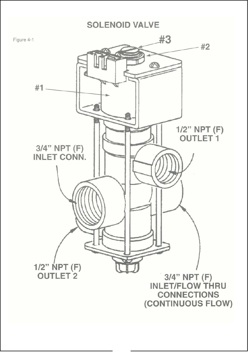
Solenoid Valve Adjustment
Refer to Figure 4-1:
NEVER REMOVE THE THROTTLING VALVE FROM
THE VALVE BODY WITH CHEMICAL IN THE
SPRAYER. DOING SO WILL CAUSE A CHEMICAL
SPILL AND WILL EXPOSE YOU TO THE CHEMI-
CALS, CAUSING PERSONAL INJURY AND DAM-
AGE TO SURROUNDING VEGETATION AND/OR
PROPERTY.
The solenoid valves must be properly adjusted in order
for the valve to stay open for long periods of time while
spraying. Also, if the solenoid is out of adjustment, the
valve may leak through the bypass port.
If sections of the boom switch off by themselves during
spraying and the coil (#1) is hot, the valve is out of ad-
justment. This can be corrected by adjusting the arma-
ture stop.
Valve Adjustment Procedure
1. Make sure that the Boom Control Switches are in
the “off position before continuing.
2. Loosen the jam nut (#2) with a box-end wrench.
3. While holding Jam Nut #2, turn the armature stop
(#3) clockwise with a large standard screwdriver
1/4 turn.
4. Now turn on corresponding switch and listen for a
“click” indication coil is energized.
5. Repeat step 4 until a “solid” contact sound is heard.
This adjustment is necessary only if you have prob-
lems with the solenoid.
6. After adjustment is made, tighten jam nut.
19
20
General Notes for Field Operation
1. Lubricate the sprayer as needed. Refer to “
Maintenance and Lubrication” section start-
ing on page 24.
2. When transporting the sprayer, do not exceed
20 mph and do not unnecessarily transport with
chemical in the tank. Fasten the level-float pin
in the lock position (if applicable) before folding
the boom and transporting it.
3. Make sure all tank shut off valves (except the
tank drain) are opened.
4. Calibrate sprayer with water only. Calibrate
with the sprayer tank half full of water. Refer to
Tee Jet Manual.
5. Adjust throttling valves on the solenoids and
the manual pressure adjustment valve.
6. Inspect and clean, if necessary, pump nozzles
and filter.
7. Make sure the material you wish to apply can
be used in your sprayer without causing dam-
age to the pump seal.
IMPORTANT
The Hy Pro pump supplied with your sprayer is not
designed for use with every application. Materials
containing solvents, paints or solutions containing
abrasives will damage the pump. If you are unsure
of your chemicals, consult your dealer for suitability
or your application.
8. Safely and carefully add the chemical to the
sprayer tank. Always wear protective equip-
ment when handling chemicals. See Personal
Safety Equipment in “Important Safety Infor-
mation” section starting on page 5. By low,
chemical containers must be rinsed three
times. The container should then be punctured
to prevent future use. An alternative is to jet-
rinse or pressure rinse the container. Follow
chemical manufacturer’s recommendations for
safe handling of chemicals.
9. Check the sprayer initially and periodically for
loose bolts, pins and hose clamps. Check the
hoses, pumps, valves and fittings for leaks.
10. Make sure that the hand wash tank is full of
clean water.
Preparing the Sprayer
NOTE
Refer to Plumbing Diagram on page 13 if you need
help identifying specific sprayer components.
1. Close drain valve, air clean out valve and filter
clean out valve.
2. Open tank and inspect interior for contaminating
materials.
3. If the sprayer is equipped with a pump drive en-
gine (in addition to the vehicle’s engine), check
fuel and oil levels.
4. Perform an electrical system check on the boom
solenoids and pressure control switch. The sole-
noid switches will emit an audible click when the
switch is opened or closed. The pressure control
valve will make noise when the pressure control
adjustment switch is engaged. If any part fails,
refer to “Troubleshooting” section starting on page
26. Turn all switches off when finished with this
step.
5. Open the pump suction valve.
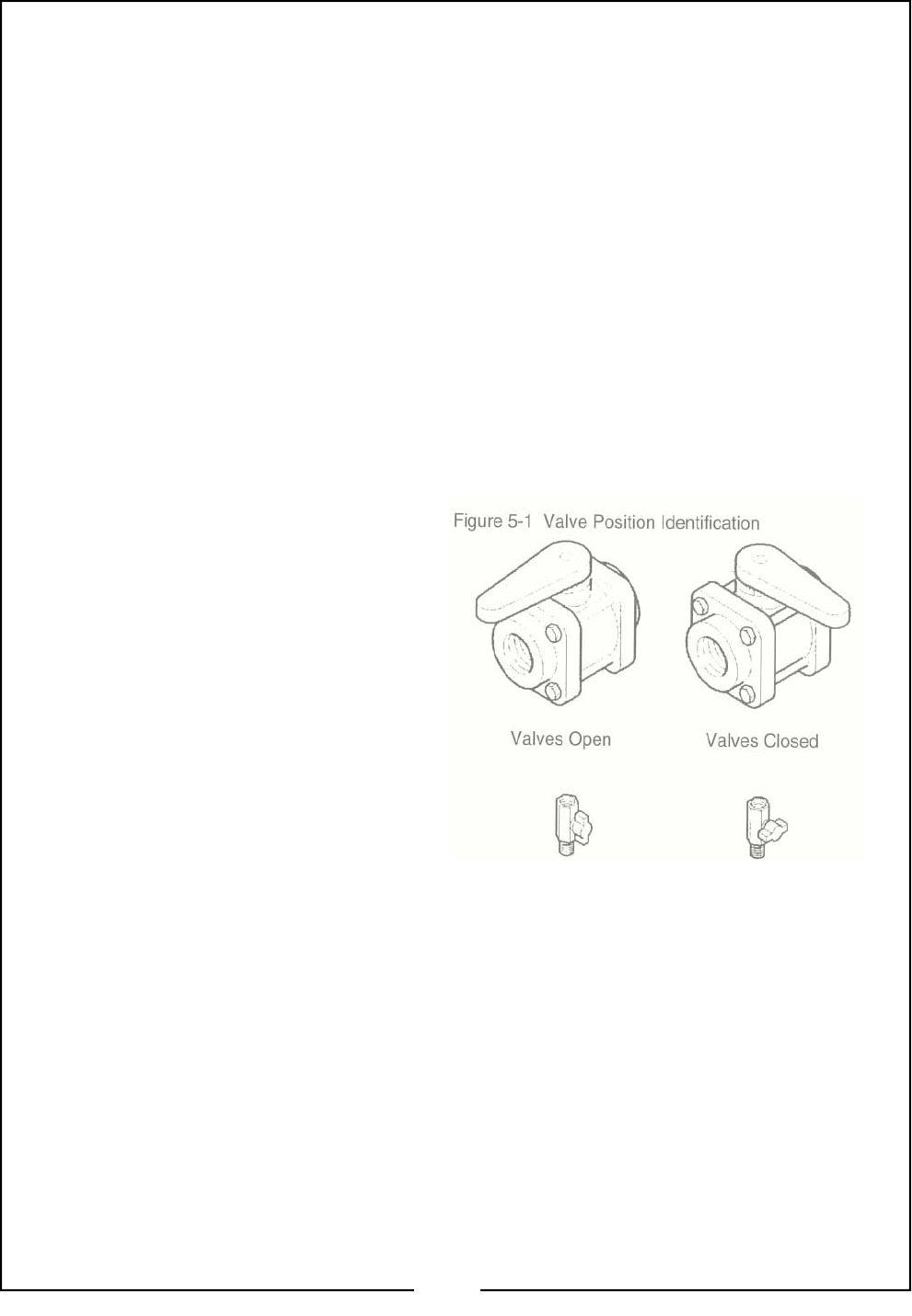
6. Open the agitation valve. Refer to Figure 5-1 if
you are not sure whether a valve is open or
closed.
Figure 5-1 Valve Position Identification
7. Open the manual pressure control valve located
next to the electric pressure control valve.
8. Extend the boom sections. Check with the Boom
Operator’s manual if you are unfamiliar with the
operation of the boom. If using a level float boom,
remove the locking pin.
9. Some booms are equipped with a ball valve at
each nozzle. If so equipped, open these valves.
10. To operate the turf boom at a 15’ width, fold the
outer sections of the boom and close the ball
valves in front of the nozzles in the outer sections.
Note: this option is not present on all booms.
11. Attach water hose to the anti-siphon fill assembly.
Make sure the knife valve is open and fill the tank
at least 1/3 full, more if performing complete sys-
tems check.
21

12. Start the vehicle’s engine (and pump engine if so
equipped), turn the master switch on (turning on the
pump) and set the throttle to maintain a minimum of
50 PSI on the agitation gauge. If agitation pressure
does not rise immediately, prime the pump by bleed-
ing air through the air clean out valve. Open the air
clean out valve and insert sharp object on the air
valve core to let air escape for ten seconds or until
water is seen at the valve. Close the air clean out
valve. An alternative method is to slightly open the
filter clean out valve, closing it once water is seen at
the valve.
13. Visually inspect hoses and all connections for leaks.
14. Refer to Tee Jet manual to determine pressure and
speed for desired chemical application rates.
15. Turn the boom section switches on and adjust the
manual pressure control valve to 10-20 PSI above
the desired operating pressure. This reduces the
sensitivity of the electric pressure control valve and
allows more precise adjustment from the control
box.
16. Calibrate throttling valves as described in the next
section. Calibration is not necessary every time the
sprayer is used but must be performed after chemi-
cal changes and to ensure the system is operating
properly. It does not harm the system to recalibrate
the throttling valves each time the sprayer is used.
17. Remove the nozzles from the check valve bodies
and flush the boom feed lines briefly by turning the
boom sections on. This will remove any debris that
may accumulate in the feed lines. Turn the boom
sections off, inspect the check valves and dia-
phragms and replace the nozzles.
18. Visually inspect nozzle spray patterns for streaking
or plugged nozzles. Clean or replace worn or dam-
aged nozzles as needed. Set the nozzle angle at 20
degrees rearward.
Calibrating The Throttling Valves
Refer to Figure 5-2:
1. Start by closing all three gray throttling valves by
loosening the jam nut and tightening the knobs all
the way down and then backing off each knob one
complete turn. Do not use excessive pressure.
2. Start the engine and turn the master switch on.
3. Turn on all three boom section switches at the con-
trol box.
4. Adjust the pressure adjust switch on the control bow
until the nozzle pressure measures 20 PSI as indi-
cated on the large gauge at the control box.
5. Turn the left boom section off. Leave the other two
sections on. This will cause the boom pressure to
increase at the other town boom sections.
6. Adjust the gray knob on the left throttling valve until
the pressure again measures 20 PSI on the large
gauge. Firmly lock the gray jam nut against the
knob to hold the knob’s position.
7. Turn the left boom section on and off several times.
If the pressure does not stay at 20 PSI, readjust the
gray knob.
8. When finished with the left boom section, proceed to
the center boom section. Turn the left boom section
on, the center boom section off and the right boom
section on. Adjust the center throttling valve in the
same manner as the one just completed.
9. When finished with the center boom section, adjust
the right boom section. Turn the right section off,
the center and left boom sections on and calibrate
the gray valve in the same manner.
All three throttling valves are now set to maintain
constant boom pressure regardless of which boom
sections are turned on.
When spraying at high gallon rates or extremely viscous
spray solutions you may see the pressure rise when all
three seciton s of the boom are turned off. This condi-
tion is caused by too much fluid trying to bypass back to
the tank agitation. As long as the boom pressure re-
turns to the desired gauge pressure when one or more
boom sections are on, there are no adverse effects on
spraying accuracy.
Adding the Chemicals
NOTE
These procedures are general guidelines for mixing
chemicals. Carefully follow the manufacturer’s instruc-
tions and use these steps in addition when applicable.
IMPORTANT
If you have not calibrated your sprayer, do so before
starting this section.
1. If using a wettable powder, make a slurry in a sepa-
rate container by adding water to the chemical, in
accordance with the manufacturer’s instructions.
22

2. Add the slurry to the sprayer tank with the pump
running and the agitation valve open. The agitation
pressure should be at 50 PSI and all boom sec-
tions should be off.
3. Add other fertilizers or chemicals once the original
slurry is circulating throughout the system. Con-
tinue filling the tank with water (or other specified
liquid carrier). Do not leave the sprayer unat-
tended.
4. Let the sprayer run for 5-10 minutes before spray-
ing the chemicals to allow adequate mixing.
5. See manufacturer’s recommendations to determine
the application rate for the desired chemical and
Tee Jet to determine the specific application pres-
sure and travel speed for your application.
6. Turn the boom on when the vehicle is moving to
prevent over-applying the chemical in any one
spot. Operate the pressure adjust switch on the
control box to adjust boom pressure while spraying.
Emptying the Tank after Spraying
1. Empty the tank while spraying whenever possible.
Closing the agitation valve when the tank is nearly
empty will allow you to almost completely empty
the tank on the field.
2. Use the drain hose to empty the tank.
NOTE
If you have access chemical remaining in the tank, it
must be handled and disposed of in an EPA approved
method. Consult the manufacturer’s label. Do not
empty chemicals into drains, sewers or onto the ground
as it can contaminate nearby water sources!
3. If you are changing chemicals or preparing the
sprayer for storage, the entire system, including
pump, hoses and boom sections needs to be emp-
tied and cleaned.
Cleaning the Sprayer
1. After emptying the sprayer tank, add clean water to
the sprayer and allow it to circulate through the
system. Spray this rinse water onto the field that
was last sprayed. While the sprayer is being
flushed on the field, turn the boom sections on to
flush out the boom sections, check valves and noz-
zles and turn them off to flush out the throttling
valves and bypass lines. Repeat this step several
times. Make sure the solenoid and throttling valves
are thoroughly cleaned. See Cleaning the Sole-
noid and Throttling Valves in next column.
2. The boom pressure gauge is equipped with a ball
valve that is used to clean out any chemical that
has built up under the gauge protector. With clean
water in the sprayer tank and the pump running
open the ball valve and allow the discharge from
the hose to flow into a bucket. After the liquid turns
clear, close the valve and return the contents of the
bucket into the tank.
Using the Air Cleanout Valve
1. Open all valves including drain valve. Allow the
tank to drain completely.
2. Open the air cleanout ball valve and attach a shop
air line (30 PSI maximum, safety clip type recom-
mended) to the air valve.
3. Close the pump suction valve located under the
tank. The air will force out any water in the agitator
line, agitator head and the line connected to the
boom pressure gauge.
4. Close all valves except the manual pressure con-
trol valve. Turn on the master, left, center and right
control switches. Allow the air to blow out all boom
feed lines, manifolds, nozzle lines, check valves
and nozzles. A whistling sound will be heard at
each nozzle when it is clear.
5. Disconnect the air line and close the valves.
6. Open the filter drain valve and allow any liquid and
foreign material in a safe and responsible manner.
Cleaning the Solenoid and Throttling
Valves
Solenoid and throttling valves must be flushed with
clean water daily to assure proper valve operation.
1. With the pump running and the master switch on,
turn on the three boom sections to flush out
sprayer nozzles.
2. Turn all boom sections off to force water through
the throttling valves and bypass line. Repeat sev-
eral times.
3. Periodically clean each throttling valve by unscrew-
ing its gray knob until it stops. Allow the valve to
thoroughly flush with water.
4. Recalibrate the throttling valves as described in the
previous section before using sprayer again.
IMPORTANT
When finished with the sprayer, make sure all switches
on the control box are off.
Protecting the Sprayer from Freezing
If the sprayer is to be stored in freezing or near-freezing
conditions, protect the pump and plumbing system by
draining and cleaning the system and pumping RV anti-
freeze solution through the plumbing system.
NOTE
Locke Turf strongly recommends the use of recrea-
tional vehicle anti-freeze.
23
Maintenance
Proper servicing and adjustment is the key to the
long life of any implement. With careful and sys-
tematic inspection, you can avoid costly downtime
and repair.
Equipment Clean Up
Cleaning your sprayer is one of the most important
parts of a regular maintenance program.
Nozzles should be cleaned with a low pressure air
hose and replaced when out of tolerance. Have a
source of water near by so you can clean the spray
tank and applicator out in a suitable location.
Never wash tank out in the yard or at a car wash.
Dispose of leftover chemical in the same manner
described on the manufacturer’s label of the chemi-
cal last used in the sprayer. Rinse out the tank and
spray the rinse water on the last area that was
sprayed.
While the sprayer is being flushed at eh field, turn
the boom section switches on to flush the nozzles,
then turn them off to flush out the throttling valves
and bypass lines. Repeat this procedure several
times. Periodically clean each throttling valve by
unscrewing the adjustment knob until it stops. Flush
it with the fresh water by operating the pump with
the boom section switches off. Reset the solenoid
throttling valves a described in Solenoids & Throt-
tling Valves on page 19.
The boom pressure gauge has a ball valve that is
used to clean out any chemical that has built up un-
der the gauge protector. With the sprayer tank full
of water and the pump running, open the ball valve
and allow the water to run in a bucket. After the liq-
uid coming out of the hose turns clear, turn off the
ball valve and dumb the contents of the bucket into
the sprayer tank.
24
GEAR CASING
(on models equipped with PTO
pump only)
IMPORTANT - Replace oil plug with
vented plug before operating pump
for proper ventilation.
Side plugs are not oil level indica-
tors. Gear case operating capacity
is 6 oz. Phillube SAE 80W90 or
equivalent. Overfilling may cause
gear case damage.
Lubrication
Legend
Multipurpose Multipurpose Multipurpose Intervals At Which
Spray/Lube Grease Lube Oil Lube Lubrication is Required
50

General Maintenance Information
BEFORE SERVICING OR MAKING ADJUSTMENTS
ON THE SPRAYER, ALWAYS DISENGAGE POWER,
SHUT OFF THE ENGINE, MAKE SURE ALL MOVING
PARTS HAVE STOPPED AND ALL PRESSURE IN
THE SYSTEM IS RELIEVED.
Check the conditions of hoses and connections fre-
quently. Release the system pressure before working
on the sprayer. To release the pressure. Flip the
boom section switches on and off without the pump
running. Always wear rubber gloves when making re-
pairs or adjustments. Make sure all personal Safety
Equipment (gloves, goggles, etc.) listed in page 6, is
stored in an easily accessible place but protected from
potential contamination from dust or chemicals.
Check the sprayer for any loose bolt, pins and hose
clamps. Check the straps holding the tank in place and
tighten when necessary.
Check the hoses, pumps, valves and fittings for any
leaks.
NEVER USE FIGERS, HANDS OR ANY PART O FY-
OUR BODY TO INSPECT THE SPRAYER! IF YOU
SUPECT A LEAK, USE A PIECE OF THICK PAPER,
CARD STOCK OR CARDBOARD INSTEAD OF
YOUR FINGERS TO FIND THE LEAK. MAKE SURE
YOU ARE WEARING ADEQUATE EYE PROTEC-
TION WHEN VISUALLY INSTECTING FOR LEAKS.
HIGH PRESSUER LIQUID CAN EASILY PENETRATE
SKIN!
Inspect all parts of the sprayer for wear and rust. Re-
pair and paint parts as necessary.
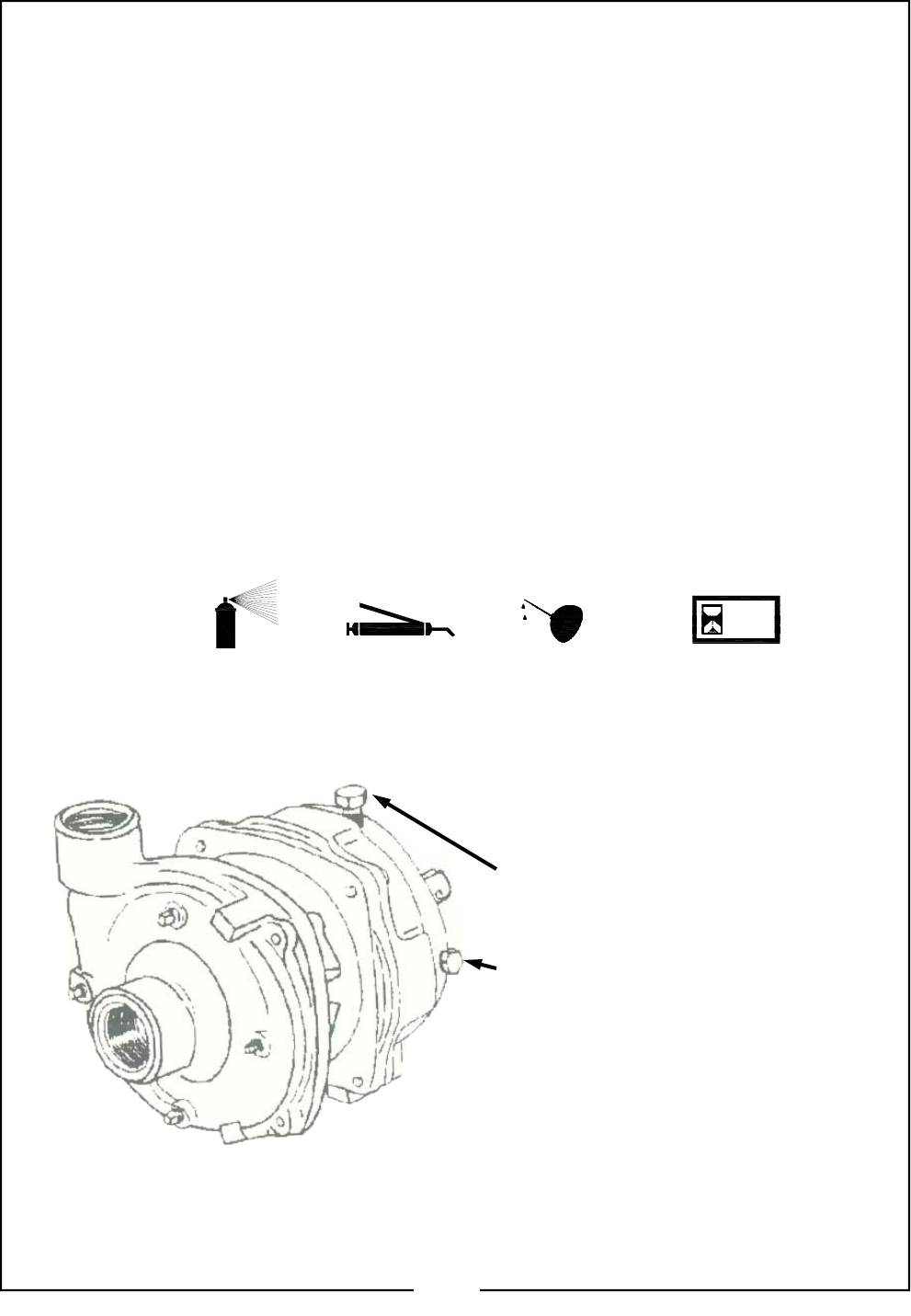
Pump Maintenance & Repair
The Hy Pro pump (also refer to Hy Pro Pump Manual)
is designed for long life and service. Eventually, there
may be a need to replace the mechanical seal or ser-
vice some component of the pump. A mechanical seal
may weep slightly but if it starts to drip, the pump will
have to be disassembled. Before you disassemble the
pump, be sure to wash it out with fresh water.
If the pump is leaking, before you remove it from the
sprayer, run the pump with adequate water in the tank
to diagnose the actual pump problem. If fluid leaks out
between the suction housing and the pump volute
housing, the housing gasket may be dried out. Give
the gasket adequate time to absorb moisture and swell
up. If necessary, retighten the volute housing by alter-
nating on opposite sides until all nuts are torqued to
16—18 ft.lbs. It is a good practice to apply grease to
both sides of the gasket to prevent shrinkage.
If the pump seal is leaking causing a drip between
the volute housing and aluminum bearing housing,
the seal may be covered with gritty chemical residue.
If the ceramic part of the seal is cracked, the pump
may have been run dry. If the pump seal spring does
not firmly attach to the impeller during assembly it will
come out of alignment and cause the seal to leak. In
this case the impeller will need replacement. Any
damage to the pinion shaft may cause pump leak-
age.
If the pump is not leaking it can be pressure tested by
closing the agitation valve and the manual pressure
control valve to build up maximum pump pressure.
At high engine speed, the pump pressure should reg-
ister 70—80 psi on the agitation gauge. If pressure
fluctuates, the impeller may be loose or clogged with
debris. The impeller can be opened and cleaned by
removing six screws in the back side of the impeller.
Carefully inspect the fiberglass housing for cracks,
especially around the webs and bolt holes. Air leaks
will prevent the pump from building up pressure.
CAUTION
CAUTION
25

SPECIFICATIONS AND CAPACITIES
Type of Sprayer
Model Number
Weight, Empty, without boom
Weight, Filled w/water, without boom
Available Booms
Tank, Poly
Boom Nozzle Height
Nozzle Spacing
Nozzles
Controls
Pump
Drive
Trailer Sprayer
TR20 (200 gallon poly)
TR30 (300 gallon poly)
20’ Level Float Boom (Manual Fold) or 20’ Electric
Fold Boom
200 gallon or 300 gallon low profile oval w/ 16”
hinged lid, fill basket, 2” anti-siphon fill assembly
w/ quick disconnect
24”
20”
TeeJet Nozzles
Manually operated electrically controlled
(standard) TeeJet 744A
One 3-1/2” 0-100 psi liquid filled gauge
One 2-1/2” 0-100 psi liquid filled gauge
TeeJet 844
Hy Pro
Vehicle PTO driven
Engine Drive (optional)
26

Quick Troubleshooting
Use this chart to help diagnose problems with the
sprayer.
Problem
Pressure Decreasing
Pressure Fluctuating
Pressure Increasing
Pressure Cannot Increase
No Pressure
Pressure Cannot Decrease
Solution
Rebuild or replace pump
Clean hose and reduce cause of clogging
Clean out or replace filter
Open gauge clean-out valve and flush gauge protector
Remove obstruction from clogged area
Align agitators properly
Replace pump housing
Remove material with soft brush or air
Remove obstruction from clogged area
Use cable ties to position hose so it will not kink
Reduce swath width by nozzle reduction; install smaller
Nozzles & drive at a lower rate of speed
Replace or repair
Test switch and replace if faulty
Replace fuse
Open the manual pressure valve all the way and allow
the electric ball valve to govern the pressure.
Make sure all tank shut-off valves are open
Tighten fittings so pump can prime
Replace hose
Remove obstruction
Switch hydraulic hoses in the pump outlet
Tighten PTO coupler
Check that the agitator valve is open and that the liquid
is being agitated
27

Detailed Troubleshooting - Pressure Problems
Use the charts in this section for specific diagnosis of sprayer problems. When troubleshooting, try the
solutions in the order presented. If the first step does not solve the problem, continue until the problem
is solved. If none of the steps solve the problem, call your dealer for help.
Problem
1. No Pressure Reading
on agitation gauge after
starting engine.
2. Pump is primed, but
very low pressure regis-
ters at agitation or con-
trol box gauge
3. Pressure gauge on con-
trol box fluctuates while
spraying.
Solution
a. Make sure there is fluid in the tanks (Yes, it has happened!)
b. Make sure that agitation valve, manual pressure control valve,
pump suction valve and bypass valve are open.
c. On electric clutch units, check drive belt. Tighten if necessary.
d. On PTO drive units, check coupler between engine and pump.
Tighten if necessary.
e. Make sure that gauge cleanout, air cleanout valve, filter drain valve
and tank drain valve are closed.
f. Check for obstructions in bottom of tank and in suction hose and
fittings.
g. Tighten all ball valves, hose clamps and fittings on suction side of
pump to stop any air leaks that prevent pump from priming.
h. Check for collapsed suction hose.
i. If unit is equipped with an electric clutch, check for power to clutch.
j. On hydraulic units, make sure vehicle’s hydraulic PTO is engaged.
k. Hydraulic lines may be disconnected or connected backwards.
a. Clean filter.
b. If filter is clean, check for chemical buildup under rubber diaphragm
in gauge protector or at gauge inlet hole if diaphragm is broken.
Replace diaphragm is broken, clean hose leading to agitation
gauge if necessary.
c. With pump operating, clean hose leading to control box gauge by
using ball valve located on remote magnet mount.
d. Check for cracked pump suction housing and volute housing. Re-
place if necessary.
a. Pump could be losing prime. Tighten all hose clamps, fittings and
valves on suction side of pump.
b. Check that the air clean out valve is closed.
c. With pump operating, clean hose leading to control box gauge by
using ball valve located on remote magnet mount.
d. If fluctuation occurs only when tank level is low, problem could by
caused by vigorous agitation or whirlpools in tank. Turn agitation
head so jets are aimed toward corners of tank.
e. To empty tank completely while spraying, turn off agitation ball
valve while spraying the last few gallons.
f. Fluctuations in engine speed will cause pressure to change. Make
sure that engine speed is constant.
g. If a filter is installed on suction side of pump, clean this filter.
h. Check for foreign matter blocking the tank or floating inside of pump
suction line.
i. On hydraulic drive units, check hydraulic fluid level. Add fluid if
needed.
28

Solution
a. On PTO drive units, check coupler between engine and pump.
Tighten if necessary.
b. With pump operating, clean hose leading to control box gauge by
using ball valve located on remote magnet mount.
c. Check gauge protector to see that it is filled with oil to within 1/8” of
top of threaded hole.
d. Swap agitation gauge and control box gauge to check for faulty
gauge.
e. Inspect electric solenoid valves to see that they are opening and
closing properly. Solenoid valves require 12 volts to open properly.
Valves may need cleaning, adjustment, repair kit or new coil. Low
voltage or a weak battery will result in valves not opening com-
pletely.
a. Check that manual pressure control valve is open.
b. Turn sprayer and engine off, hold the pressure adjust switch and
listen at the electric pressure control valve for whirring sound which
indicates that the motor is turning the valve.
c. With the engine running, visually inspect the nozzles to see if the
pressure is changing. If pressure is changing, clean hose leading
to control box gauge by using ball valve located on remote magnet
mount. If problem persists, swap agitation gauge and control box
gauge to check for faulty gauge.
d. If whirring sound is not heard, check electrical connections and fuse
in the control box.
e. If fuse is good, check with 12 volt tester to see fi pressure adjust
switch is receiving current from fused wire and sending signal to the
electric pressure control valve. Replace switch if faulty.
f. If current is good, check with 12 volt tester to see if pressure adjsut
switch is receiving current from fused wire and sending signal to the
electric pressure control valve. Replace valve if faulty.
a. Check electric pressure control valve operation as follows: With unit
spraying, hold the pressure adjust switch up. The pressure on the
control box gauge should increase to a maximum pressure, remain
high for about 10 seconds and then drop to minimum pressure.
Check wire connections, valve operation and voltage to switch and
valve. Replace valve if necessary.
b. Tank agitation may be restricted. Check that agitation valve is
open and agitator head has four jet streams shooting out.
c. Relieve excess pressure on electric pressure control valve. Open
electric pressure control valve to maximum pressure, then close the
manual control valve unit control gauge reads 15-20 psi above de-
sired nozzle pressure.
a. Check application guide for flow rate and catch nozzle flow to deter-
mine pressure drop.
b. Swap agitation gauge and control box gauge to check for faulty
gauge.
c. Check for clogged or pinched boom feed lines from solenoids.
d. Inspect electric solenoid valves to see that they are opening and
closing properly (Page 19). Solenoid valves require 12 volts to
open properly.
Valves may need cleaning, adjustment, repair kit or a new coil.
Low voltage or a weak battery will result in valves not opening com-
pletely.
Problem
4. Agitation gauge registers
pressure but control box
gauge reads zero or is very
sluggish after nozzles are
turned off.
5. Moving the pressure adjust
switch on the control box does
not change nozzle pressure
but both gauges show some
pressure.
6. Nozzle pressure cannot be
reduced below 20-30 psi.
7. During calibration control
box gauge reads about 30 psi.
Nozzles are spraying about 10
psi. When catching flow of
nozzles, there is a large pres-
sure drop.
29

Solution
a. Throttling valves are becoming plugged. Open gray throttling
valve with nozzles turned off and allow flow to flush out valves
for about 15 seconds per valve. Reset throttling valves.
a. Throttling valves are becoming plugged. Unscrew gray knob on
throttling valve with boom sections turned off and allow to flow to
flush out valves for at least 15 seconds per valve. Reset the
throttling valves when finished.
b. Look for a restriction in the bypass line between the throttling
valves and the tank. If nozzle pressure returns to normal when
one or more boom sections are turned on, spraying accuracy is
unaffected.
a. Check GPM flow to be sure that pump has the capacity to spray
the desired volume.
b. Change to smaller size nozzles.
c. Reduce flow to agitation by partially closing agitation valve Make
sure that there is still adequate agitation after adjusting.
d. Check to be sure that manual pressure control vavle is open.
e. Increase engine RPM to increase pump output.
a. Low Flow: Check the boom feed line for that boom section for
blockage or kinks. Inspect check valves, nozzles, metered
manifold and electric solenoid valves for obstructions and chemi-
cal buildup. Remember, low voltage or a weak battery will result
in valves not opening completely. Check hose length leading to
manifold. If hose length is considerably longer than other sec-
tions, cut hose length to match length of other boom sections.
b. High flow: Check the boom feed line for that boom section for
length. If feed line is much shorter than other boom sections,
replace with longer line. Check to see that all nozzles are the
same size.
a. Recheck calibration.
b. Ground speed is slower than calibrated speed. Recheck speed
using method in application guide.
c. Check to make sure all nozzles are correct and the same size.
One oversized nozzle will result in over-application.
d. Check nozzle spacing.
e. Check control box gauge.
f. Overlap of rows may be too great causing double application in
some area.
g. Check levels in tank. Less than calculated amount would falsely
indicate over application.
h. Check for worn nozzles. Nozzles should be within 10% of
specs. Replace if necessary.
i. Check for possible wheel slippage.
Problem
8. Suspect faulty control box
gauge because pressure
changes when turning off
boom sections.
9. After correctly setting the
throttling valves, boom pres-
sure will not stay constant
when a section of the boom is
turned off.
10. Cannot increase boom pres-
sure to desired setting al-
though pump and plumbing
systems are set and operat-
ing correctly
Plumbing Problems
11. Flow to one boom section is
different than flow to other
boom sections (as con-
firmed by catching flows of
each nozzle).
12. Too much material is being
applied; rate is not as cali-
brated.
30

Solution
a. Recheck calibration.
b. Ground speed is faster than calibrated speed. Recheck speed
using method in application guide.
c. Nozzle size smaller than size used for calibration.
d. If the pressure at the manifolds and nozzles is less than pres-
sure at the control box gauge (#3), feed lines to booms may
need to be cleaned.
e. Check for worn nozzles. Nozzles should be within 10% of
specs. Replace if necessary.
f. Check the travel pattern. Not enough overlap during spraying
may result in under-application by leaving areas unsprayed.
g. Check control box gauge. IF actual rate is less than gauge indi-
cates, suspect a faulty gauge.
h. Check levels in tank. IF tank level was more than amount cal-
culated, a false underapplication condition occurs.
I. Check for filter screen blockage.
j. Check for loose pump impeller bolt.
k. Check for clogged impeller channels. (Requires pump diassem-
bly; try all other options first.)
a. Check nozzles for obstructions in feed holes. Clean nozzles
with toothbrush or suitable brush. Steel picks, nails, etc. will
damage the nozzle.
b. Inspect the check valve in front of each nozzle. Clean and in-
spect rubber diaphragms. The correct rubber viton diaphragm is
marked with a “v”. EPDM rubber diaphragms will become swol-
len and will not work.
c. Check hose barbs screwed into the metered manifolds. If hose
barbs are screwed too far into the manifold, flow can be re-
stricted.
a. Disassemble diaphragm cap from body and check that the cap
spring moves freely.
b. Inspect the diaphragm. Clean or replace if necessary.
c. Increase spraying pressure. About 15 psi is required at the
check valve to hold it open.
d. Check the control box gauge for faulty reading.
a. Clean diaphragm in check valve at nozzle. Look for debris or
nicks which would allow leakage.
b. If problem still appears, check solenoid valve for that section for
proper adjustment of foreign matter on the seat washers in the
valve. Replace washers and seals with valve repair kit if neces-
sary.
Problem
13. Not enougn material is be-
ing applied; rate is not as
calibrated.
14. Nozzle flows across boom
are inconsistent and vary
several ounces high or low.
15. Diaphragm check valves at
nozzles will not stay open
while spraying.
16. Nozzles continue to spray or
dribble after boom is turned
off.
31

Solutions
a. Angle nozzles 20 degrees rearward.
b. Nozzle cap is obstructed or scratched. Clean nozzle gently with
water or solvent, using a toothbrush to clean the orifice hole in the
cap. Use a pipe cleaner to clean the metering feed hole in the
body. Steel picks, nails, etc. will damage the nozzle.
c. Disable the nozzle and clean inside surfaces, threads and any
sealing surfaces where the cap meets the body. Carefully inspect
the cap and body for any nicks, wear or chemical buildup. Tighten
nozzle cap firmly with torque wrench to 30 ft.lbs.
d. If nozzle output is high, the metering feed hole or internal cavity is
worn. Replace the nozzle.
e. Check nozzle spacing for correct overlap. Use 20” spacing on turf
booms.
f. Make sure that windy conditions are not affecting the spray pattern.
g. Check boom height.
a. Debris catching in throttling valves. Open gray throttling vale with
nozzles turned off and allow flow to flush out valves for about 15 sec-
onds per valve. Reset throttling valves.
b. If problem continues, replace filter screen with 50 mesh screen.
a. Check for proper lid fit.
a. Make sure agitation valve is open.
b. Check for obstructions or kinks on the agitation line.
c. Inspect agitator head for plugged holes.
d. Increase flow and pressure to agitation by increasing pump seed.
Do not exceed 4000 RPM or 90 psi.
e. Make sure chemicals were mixed properly. Do not allow chemi-
cals to settle in tank.
f. Agitate longer before spraying.
a. Check housing for cracks.
b. Housing gasket may be dried out and leaking. Allow gasket time
to absorb moisture and retighten bolts around housing in an even
manner.
c. Seal leaking, causing drip between pump and bearing housing. If
pump has been run dry, seal may be cracked. Replace seal.
d. Pinion shaft may be damaged at sealing surfaces. Replace.
a. Loosen end caps, then retighten equally to keep internal parts
from shifting.
b. If still leaking, disassemble valve and check that o-rings are in
good condition. Replace if necessary.
Problem
17. Nozzle shows streaking or a
collapsed pattern; nozzle
drips while spraying.
18. Throttling valves must be
readjusted after each tank
sprayed.
19. Liquid leaks out around tank
lid while spraying.
20. Chemicals will not stay in
suspension.
21. Pump leaks.
22. Ball valve leaks.
32

Solution
a. Check electrical connections and battery charge. Valves may
need cleaning, armature stop adjustment, repair kit or new coil.
Low voltage or a weak battery will result in valves not opening com-
pletely.
b. Check output of alternator or battery. (See vehicles owner’s
manual)
a. Solenoid plunger is not functioning. Plunger may be seized up
or coil may be bad.
b. Physically cycle solenoid valve by pushing up at bottom of sole-
noid several times. If it will manually open and close, check electri-
cal switching.
c. Clean inside of solenoid if some movement occurs when electri-
cally operating valve.
d. Clean terminals on solenoid coil.
e. Test coil by exchanging it with working coil from adjacent sole-
noid valve.
f. Replace coil.
g. Install solenoid seal repair kit.
a. Check boom section feed lines to see that they are connected to
the correct boom sections.
b. Switch wires on top of solenoid valves to correct order.
a. Check to see that fuse is correct size. (15-20 amps)
b. Check for short circuit between switch ternimals inside control
box. Carefully separate touching wires.
c. Inspect wiring harness for bare wires, rub points or any damage.
a. Check battery terminals. Clean if necessary.
b. Check water level in battery. Add distilled water and charge if
necessary. (See vehicle owner’s manual)
c. Sprayer components depleting vehicle battery. Allow vehicle to
idle briefly after spraying (with all pumps, foam markers, etc. off) to
allow battery to fully charge.
d. Weak battery. Test and replace if necessary.
a. Driveshaft out of alignment. Realign shaft.
Problem
23. Solenoid valves shut off or
partially close while spray-
ing.
24. Solenoid valve will not click
open but has adequate
power (checked by switch-
ing wires to adjacent sole-
noids.)
25. Control box switches oper-
ate the wrong boom sec-
tions.
26. Control box blows fuse.
27. Vehicle battery low.
Mechanical Problems
28. Sprayer makes chattering
noise when pump is turned
on.
Electrical Problems
33
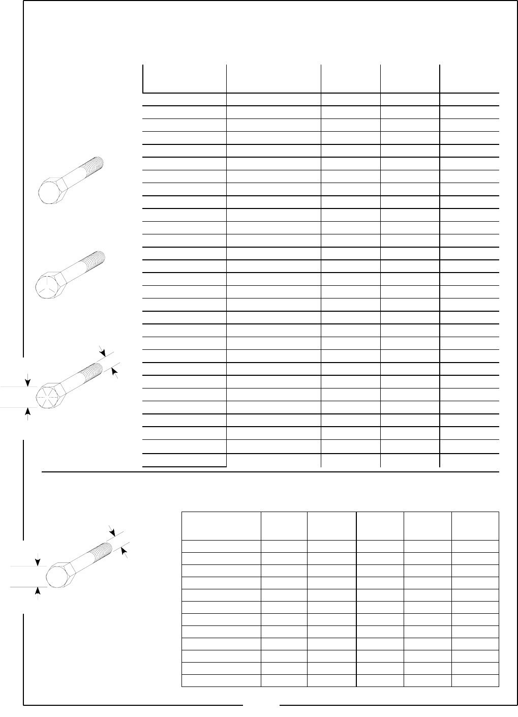
TORQUE SPECIFICATIONS
Proper torque for American fasteners used on Locke Turf equipment.
Recommended Torque in Foot Pounds (Newton Meters). *
WRENCH
SIZE
(mm) “A”
BOLT
DIA.
(mm) “B”
ASTM
4.6 ASTM
8.8 ASTM
9.8 ASTM
10.9
8 5 1.8 (2.4) 5.1 (6.9) 6.5 (8.8)
10 6 3 (4) 8.7 (12) 11.1 (15)
13 8 7.3 (10) 21.1 (29) 27 (37)
16 10 14.5 (20) 42 (57) 53 (72)
18 12 25 (34) 74 (100) 73 (99) 93 (126)
21 14 40 (54) 118 (160) 116 (157) 148 (201)
24 16 62 (84) 167 (226) 181 (245) 230 (312)
30 20 122 (165) 325 (440) 449 (608)
33 22 443 (600) 611 (828)
36 24 211 (286) 563 (763) 778 (1054)
41 27 821 (1112) 1138 (1542)
46 30 418 (566) 1119 (1516) 1547 (2096)
Bolt
Diameter "B"
Wrench
Size "A" 8.8
Numbers appearing on bolt heads
Indicate ASTM class.
*Use 75% of the specified torque value
for plated fasteners. Use 85% of the
specified torque values for lubricated
fasteners.
METRIC
Proper torque for American fasteners used on Locke Turf equipment.
Recommended Torque in Foot Pounds (Newton Meters). *
WRENCH
SIZE (IN.) “A” BOLT DIAMETER
(IN.) “B” AND
THREAD SIZE
SAE
GRADE 2 SAE
GRADE 5 SAE
GRADE 8
7/16 1/4 –20 UNC 6 (7) 8 (11) 12 (16)
7/16 1/4 –28 UNF 6 (8) 10 (13) 14 (18)
1/2 5/16 – 18 UNC 11 (15) 17 (23) 25 (33)
1/2 5/16 – 24 UNF 13 (17) 19 (26) 27 (37)
9/16 3/8 – 16 UNC 20 (27) 31 (42) 44 (60)
9/16 3/8 – 24 UNF 23 (31) 35 (47) 49 (66)
5/8 7/16 – 14 UNC 32 (43) 49 (66) 70 (95)
5/8 7/16 – 20 UNF 36 (49) 55 (75) 78 (106)
3/4 1/2 – 13 UNC 49 (66) 76 (103) 106 (144)
3/4 1/2 – 20 UNF 55 (75) 85 (115) 120 (163)
7/8 9/16 – 12 UNC 70 (95) 109 (148) 153 (207)
7/8 9/16 – 18 UNF 79 (107) 122 (165) 172 (233)
15/16 5/8 – 11 UNC 97 (131) 150 (203) 212 (287)
15/16 5/8 – 18 UNF 110 (149) 170 (230) 240 (325)
1-1/8 3/4 – 10 UNC 144 (195) 266 (360) 376 (509)
1-1/8 3/4 –16 UNF 192 (260) 297 (402) 420 (569)
1-5/16 7/8 – 9 UNC 166 (225) 430 (583) 606 (821)
1-5/16 7/8 – 14 UNF 184 (249) 474 (642) 668 (905)
1-1/2 1 –8 UNC 250 (339) 644 (873) 909 (1232)
1-1/2 1 – 12 UNF 274 (371) 705 (955) 995 (1348)
1-1/2 1 – 14 UNF 280 (379) 721 (977) 1019 (1381)
1-11/16 1-1/8 – 7 UNC 354 (480) 795 (1077) 1288 (1745)
1-11/16 1-1/8 – 12 UNF 397 (538) 890 (1206) 1444 (1957)
1-7/8 1-1/4 – 7 UNC 500 (678) 1120 (1518) 1817 (2462)
1-7/8 1-1/4 – 12 UNF 553 (749) 1241 (1682) 2013 (2728)
2-1/16 1-3/8 – 6 UNC 655 (887) 1470 (1992) 2382 (3228)
2-1/16 1-3/8 – 12 UNF 746 (1011) 1672 (2266) 2712 (1992)
2-1/4 1-1/2 – 6 UNC 870 (1179) 1950 (2642) 3161 (4283)
2-1/4 1-1/2 – 12 UNF 979 (1327) 2194 (2973) 3557 (4820)
AMERICAN
Bolt Head Markings
SAE Grade 2
(No Dashes)
SAE Grade 5
(3 Dashes)
Bolt
Diameter "B"
t
"
Wrench
Size "A" SAE Grade 8
(6 Dashes)
34

Locke Turf
307 Highway 52E, Opp, Alabama, 36467, (334) 493-1300
