Locks 692 Series Smart Bar Instructions 104599
User Manual: Locks 692 Series SmartBar Instructions Mayflower Sales - Schlage Electronics
Open the PDF directly: View PDF ![]() .
.
Page Count: 6
*941139-00*
941139-00
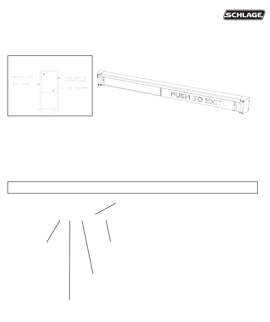
TouchBar
692
Installation and Wiring Instructions
WHAT MODEL DO YOU HAVE?
EXAMPLE: 692-36-628-RD-RHR-WD
DOOR WIDTH:
36”
42”
48”
PUSHPAD:
RD RED EXIT
GID GLOW IN DARK EXIT
OPTIONS:
WD Sex nuts/screws for wood or hollow metal door applications
SHK Aluminum door mounting shim kit (screws included)
TYPICAL INSTALLATION:
BAR FINISHES:
628 Satin aluminum
313 Dark Satin Bronze
HANDING:
RHR or LHR (Shown above)
To change hand (if required) see page 2.
GENERAL DESCRIPTION: The 692 Series TouchBar is a non-latching releasing device which uses two photo beams
to detect intention to exit. Breaking either or both beams will deactivate the relay. Loss of power to the device will also
deactivate the relay. It is most often used as a switch to release a magnetic lock. A double pole output is standard.
The device can be ordered to fit 3 standard door openings. A 24-inch (minimum) pre-connected cable comes standard
to make installation easier. These devices are to be installed in accordance with the applicable codes and the local
authorities having jurisdiction. It is up to local authority having jurisdiction whether this can be installed in lieu of panic
hardware.
ELECTRICAL SPECIFICATIONS: INPUT RATING: 12/24 VOLTS DC @500mA MAX.
CONTACT RATING: 4 AMPS @ 30 VDC

WIRE HOLE
LOCATION:
Note that hole size
depends on fastener
type (SEE STEP 3).
WIRE HOLE IS ALWAYS
ON HINGE SIDE OF FRAME
STEP 2 LOCATING AND DRILLING THE WIRE HOLE
a. On the hinge-side of door, mark a horizontal centerline at the desired height for the TouchBar.
b. Place a channel end cap bracket over the centerline.
c. Center wire hole in the adaper plate with the centerline that was marked on door. (See below)
d. Mark center of wire hole and center of one mounting hole.
d. Drill a 5/8” wire access hole at wire hole mark. DO NOT DRILL WIRE HOLE THRU DOOR.
SWITCH SIDE
END CAP
SEE BACK COVER FOR COMPLETE EXPLODED VIEW.
CHANGING HAND:
REMOVE END CAP AND BEAM
HOUSING. REMOVE PUSH TO EXIT
SIGN AND INSERT AND REVERSE
LETTER DIRECTION. SET SWITCH
POSITION (SEE FACTORY WIRING
ON PAGE 4). RE-INSTALL BEAM
HOUSING AND END CAP
REFERRING TO THIS PAGE.
COVER PLATE
INSERT
PUSH PAD
STEP 1 VERIFY CORRECT HAND.
Note: devices ordered specifically for the job should not need to be handed.
BEAM HOUSING
ASSEMBLY
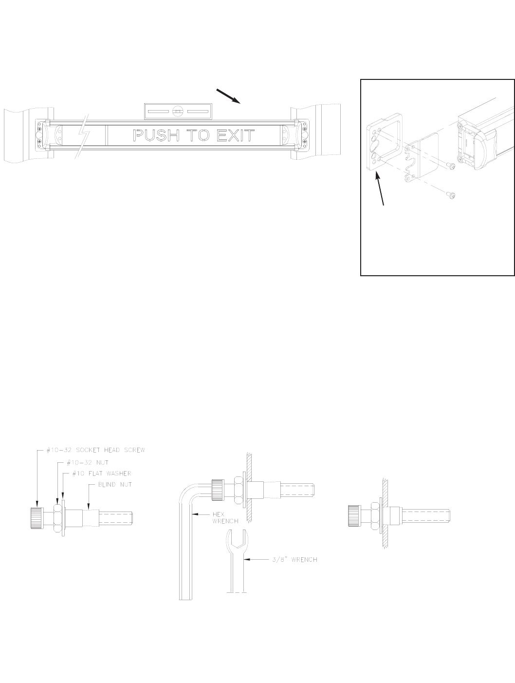
BLIND NUT INSTALLATION:
a. Drill four 9/32” holes on device side only of door in positions marked in step 3.
b. Install blind nuts as shown to right.
c. Secure device using #10-32 socket cap screws.
I. Assemble tool to install blind
nut as shown using the parts
supplied.
II. Install blind nut assembly
into pre-drilled 9/32” hole in
door. Hold the socket head
screw firmly with the hex
wrench to prevent rotations as
shown.
III. Using a 3/8” wrench, rotate
the nut clockwise until the nut
collapses against the inside of
the door skin. Some resistance
will be felt. Carefully tighten
until nut is secure.
Do not overtighten.
STEP 3 MARK AND DRILL MOUNTING HOLES
Fasten TouchBar to door. There are three methods of fastening the device to the door:
SELF DRILLING SELF TAPPING SCREWS:
a. Hold device in position determined in step 3.
b. Using a powered screw driver, screw in one screw on one side.
c. Level the device. Secure other side with self drilling screw.
d. Install remaining two screws.
WD OPTION - SEX NUTS FOR WOOD DOORS:
a. Drill four 13/32” holes thru door in positions marked in step 3.
b. Using a rubber mallet, hammer in sex nuts from opposite side of door.
c. Secure device using #10-24 pan head screws.
USE A LEVEL WHEN MARKING HOLES
ALUMINUM DOOR MOUNTING
SHIMS MUST BE USED FOR ALL
NARROW STYLE ALUMINUM
DOORS. THEY CAN BE OMITTED
FOR HOLLOW METAL AND WOOD
DOORS.
SHK Option for REX
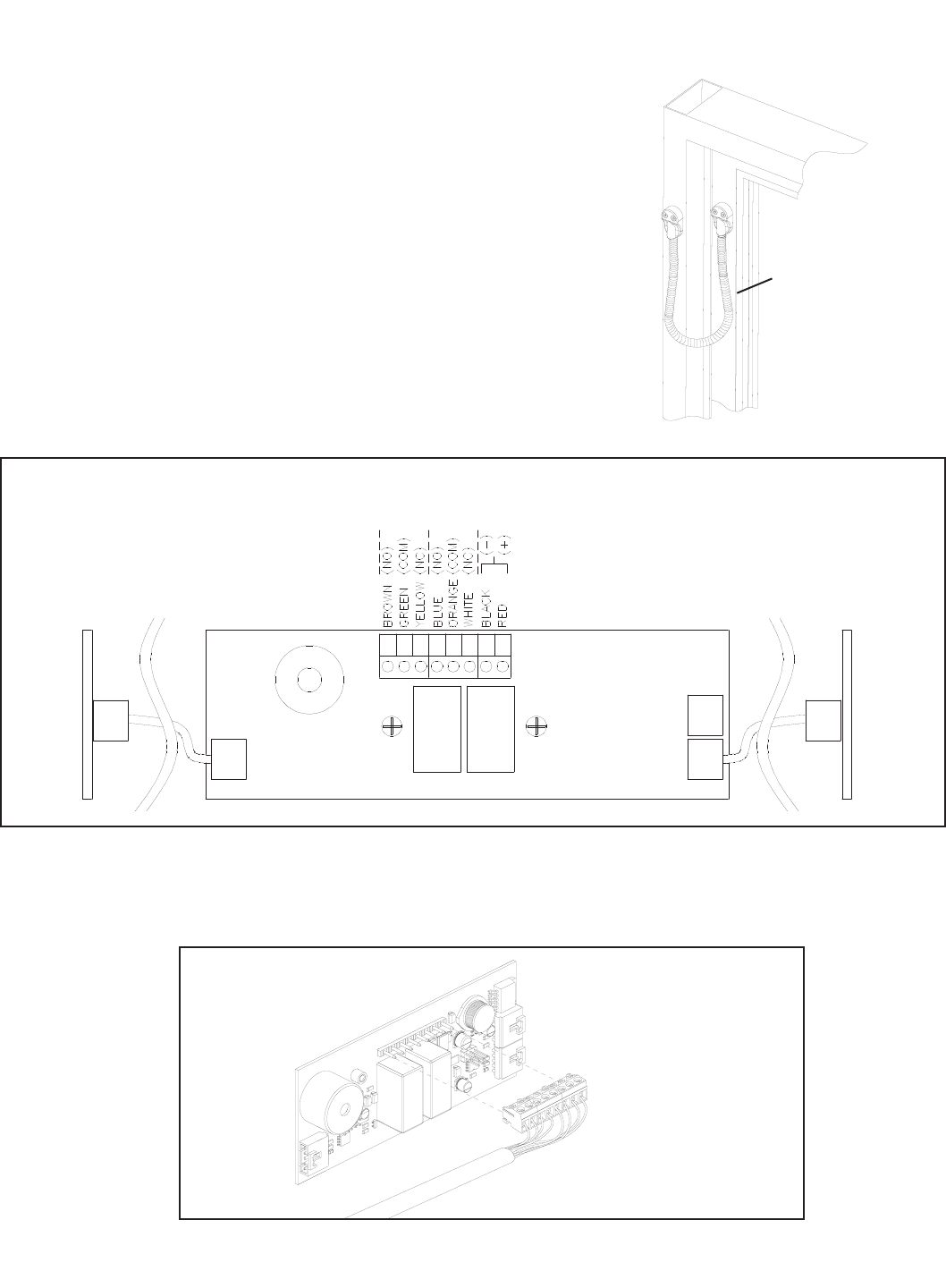
FACTORY WIRING:
THIS INFORMATION IS SHOWN FOR TROUBLE-SHOOTING PURPOSES. DO NOT MODIFY FACTORY WIRING.
IMPORTANT:
IF WIRING HARNESS
MUST BE REMOVED
IT MUST BE PUT
BACK IN CORRECT
ORIENTATION AS
SHOWN.
STEP 4: WIRING
Provision must be made to get wiring to the device on the door.
Common methods are an electric hinge, door cord, or power
transfer device. A model 798-18 Armored Door Cord Kit is
included as standard equipment with each 692 TouchBar to
facilitate power transfer. Make wiring connections as required
by the system wiring diagram.
See next page for typical wiring methods. 798-18 Door Cord
(690038-18)

DOUBLE DOOR - TYPICAL
SINGLE DOOR - TYPICAL
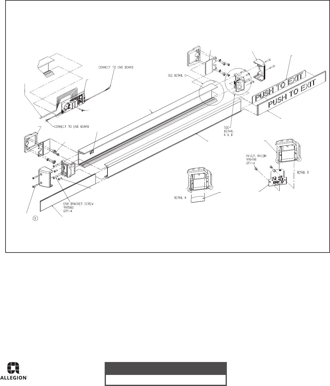
DETAIL C
SCREW
990584
QTY-4
COVER PLATE
972769 36"
972770 42"
972771 48"
QTY-1
WIRE HARNESS
114287
SCREW
990583
QTY-4
ALUMINUM DOORS
MOUNTING SHIMS
900275
QTY-2 MOUNTING
SCREW PACK
900256
QTY-1
STRAIN RELIEF
972802
CABLE TIE
972801
CABLE ASSY
114284 QTY-2
SCREW
6-32 X 3/4 PH TRUSS HD
990073 QTY-1
CONTROL
BOARD
ASSY
114285
CHANNEL
972781 36"
972782 42"
972783 48"
QTY-1
PUSH BAR
972772 36"
972773 42"
972774 48"
QTY-1
LENS
972798
QTY-2
END CAP
BRACKET
972797
QTY-2
CHANNEL
END CAP
972784
QTY-2
EXIT INSERT
972792 RD
972794 GID
QTY-1
EXIT PLATE
972791
QTY-1
END CAP
972787
QTY-2
PC BOARD
ASSY
114286
QTY-2
PARTS BREAKDOWN:
TROUBLE-SHOOTING TIPS:
:KCEHC:MELBORP
.sdnoces 51 naht erom rof dekcolb maeBGNIPEEB SUOUNITNOC
BEEPS TWICE INTERMITTENTLY Too much light getting into detector.
BEEPS AND CLICKS ON POWERUP Normal self-test.
DOES NOT WORK W/ POWER APPLIED Cycle power off then on again. (Always have good connections
before applying power.)
Customer Service
1-877-671-7011 www.allegion.com/us
© Allegion 2014
Printed in U.S.A.
941139-00 Rev. 01/14-c
