Locks 620142 F 620/631 Series Pushbuttons Instructions 105906 1
User Manual: Locks 620/631 Series Pushbuttons Instructions Mayflower Sales - Schlage Electronics
Open the PDF directly: View PDF ![]() .
.
Page Count: 1
620142
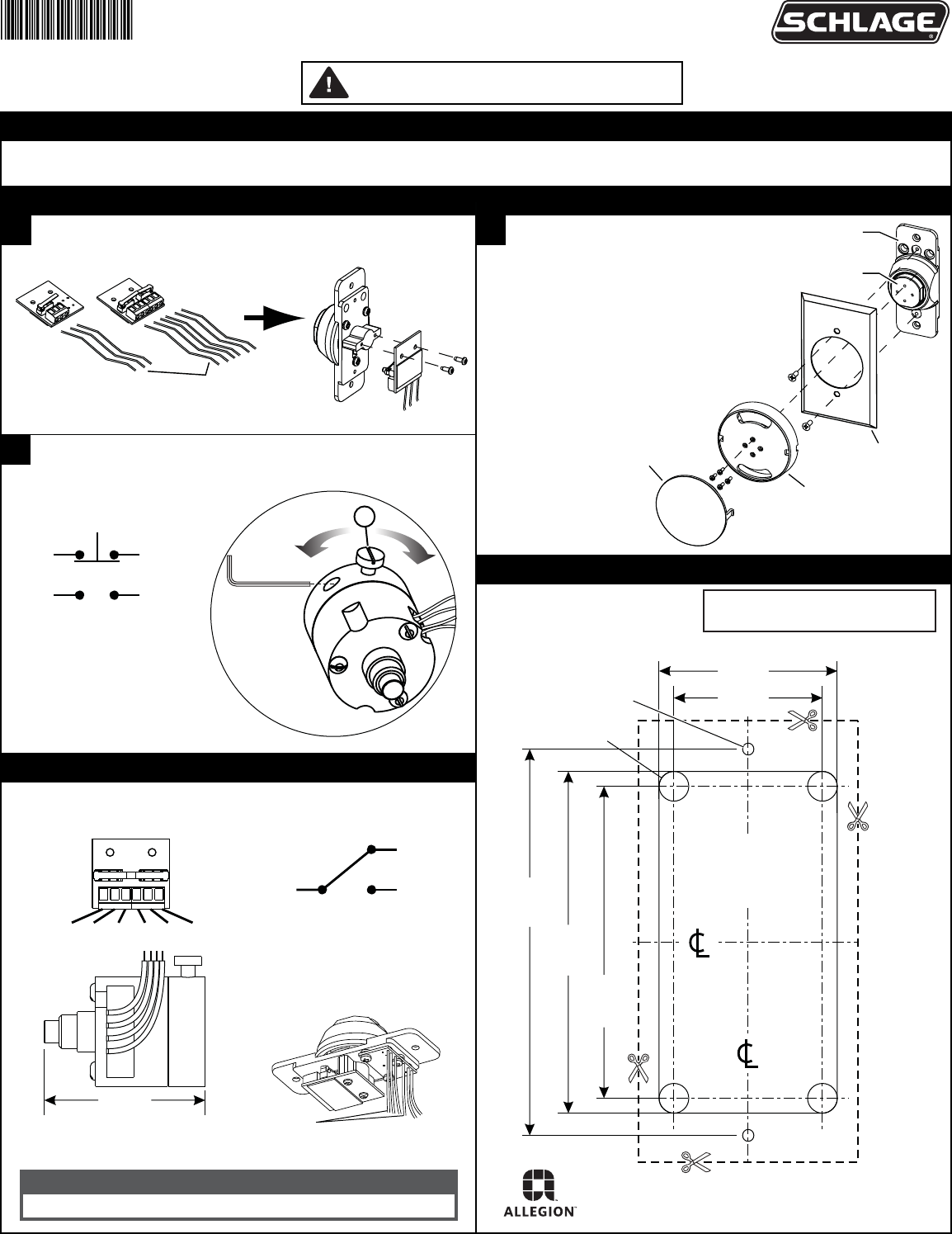
620 and 631 Series Pushbuttons
Installation Instructions and Template
Information
Instructions
Template
Additional Info
1Install system wiring (see PCB for contact positions). Screw
PCB assembly onto switch housing using screws provided.
3All DA Pushbuttons 5A @ 30VDC
After adjusting delay with screw (a), use the provided 1/16” hex
wrench to tighten set screw.
2On Large Mushroom Pushbuttons:
1. Make wiring connections.
2. Mount switch body.
3. Install cover plate.
4. Screw button body onto pushbutton
base using screws provided.
5. Snap pushbutton cover onto
pushbutton body in correct orientation.
The 620 and 631 Series Pushbuttons mount in a standard single-gang box. 620-NS & 631-NS pushbuttons mount with prep shown below.
Cut out template or follow mounting prep dimensions.
DO NOT PHOTOCOPY THIS DOCUMENT!
TEMPLATE MUST BE TO SCALE.
LEDS OPERATE AT:
12-24 VDC
0.025A@28VDC
RED, GREEN, YELLOW ( + )
BLACK ( - )
LED WIRES
NOTE: BLACK WIRE NEXT TO COLORED
WIRE IS THE COLORED WIRE'S GND.
MOMENTARY (STANDARD)
STANDARD: 3A@30VDC
NC C NO NC C NO
AA PUSHBUTTONS
3A @ 30VDC
BLACK
(C)
RED
(N.C.)
WHITE
(N.O.)
system wiring
(by others)
switch
housing
pushbutton
base
pushbutton cover
pushbutton body
cover plate
6-32 Thread
TYP (2)
1/4" (0.250") Hole
Drill 4 places
2 7/8"
3 1/4"
2 5/8"
1 1/4"
Remove material to
a depth of 1-3/4"
(1.750") minimum.
1 1/2"
(3.250")
(2.875")
(2.625")
(1.250")
(1.500")
Recommended cutout
for 620-NS and 631-NS
narrow pushbuttons.
RED
(N.C.)
WHITE
(N.O.)
RED
(N.C.)
WHITE
(N.O.)
2-13/64
1/16"
hex wrench
a
faster slower
NOTE: Standard pushbuttons can
be mounted using same cutout.
© Allegion 2015
Printed in U.S.A.
620142 Rev. 8/15-f
Customer Service
1-877-671-7011 www.allegion.com/us
