Loea L1000-2 Point to Point Radio User Manual L1000 UserManual rev121007
Loea Corporation Point to Point Radio L1000 UserManual rev121007
Loea >
Manual

L1000 User’s Manual
DU1000-01 11/26/07
Loea Corporation
733 Bishop Street Suite 1717
Honolulu, HI 96813
Phone: (808) 521-4908
Fax: (808) 521-4906
www.loeacom.com
User’s Manual
L1000 Millimeter-wave
Point-to-Point Radio System
Version Beta 1.0
November 26, 2007

L1000 User’s Manual
DU1000-01 11/26/07
Loea Corporation
733 Bishop Street, Suite 1717
Honolulu, HI 96813
Phone: (808) 521-4908
Fax: (808) 521-4906
www.loeacom.com
2
Table of Contents
GENERAL SAFETY NOTICES................................................................................................. 4
GENERAL SAFETY NOTICES................................................................................................. 4
1. OVERVIEW.......................................................................................................................... 6
1.1 DESCRIPTION.................................................................................................................. 6
1.2 L1000 COMMON APPLICATIONS AND FEATURES.......................................................... 6
2. INSTALLATION PROCEDURES ..................................................................................... 8
2.1 INTRODUCTION............................................................................................................... 8
2.2 STANDARD LINK COMPONENTS..................................................................................... 8
2.3 GENERAL INSTALLATION REQUIREMENTS ................................................................... 9
2.4 STEERING/MOUNTING SYSTEM (FS001000) ............................................................... 10
2.4.1 Assemble Mount................................................................................................... 11
2.4.2 Attach the Mast Clamp Brackets .......................................................................... 12
2.5 ATTACH ASSEMBLY TO MAST (SEE FIGURE 6)............................................................ 13
2.6 ATTACH TRANSCEIVER TO STEERING SYSTEM (SEE FIGURE 7)................................. 14
2.7 CABLING TO THE RADIO (SEE FIGURE 8)..................................................................... 15
2.8 BENCH TESTING RADIOS.............................................................................................. 19
2.9 INTERFACING TO RSSI PORT (SEE FIGURE 14)........................................................... 21
2.10 ALIGNMENT TECHNIQUES (SEE FIGURE 16)................................................................ 23
2.11 VERIFICATION OF BIT ERROR RATE (BER)................................................................ 25
2.12 FINAL SYSTEM COMMISSIONING ................................................................................. 25
3. SYSTEMS INTEGRATION.............................................................................................. 26
3.1 STANDARD SYSTEM DEMARCATION BOX REQUIREMENTS......................................... 26
3.2 BASIC INFORMATION ON LOEA INTERFACE................................................................ 26
3.3 LINK MONITORING ...................................................................................................... 27
3.3.1 Network Management System Operation............................................................. 27
3.3.2 NMS Data Transfer............................................................................................... 27
3.4 RS-232 SERIAL LINK INTERFACE................................................................................ 28
3.5 GROUNDING PROCEDURES........................................................................................... 32
3.5.1 Single Point Grounding......................................................................................... 32
3.5.2 Rack Cabinet Grounding....................................................................................... 34
3.5.3 An Effective Earth Ground................................................................................... 35
3.5.4 At the Tower ......................................................................................................... 36
3.5.5 Conclusion ............................................................................................................ 37
APPENDIX A - FIELD SERVICE FORM .............................................................................. 39
APPENDIX B – LIST OF SNMP MIB GROUPS ................................................................... 41
APPENDIX C –EXAMPLE OF INSTALLING THE L2700 MIB ........................................ 44

L1000 User’s Manual
DU1000-01 11/26/07
Loea Corporation
733 Bishop Street, Suite 1717
Honolulu, HI 96813
Phone: (808) 521-4908
Fax: (808) 521-4906
www.loeacom.com
3
List of Figures and Tables
FIGURE 1. TYPICAL L1000 APPLICATIONS....................................................................................... 6
FIGURE 2. L1000 MOUNTED ON 4” MAST........................................................................................ 7
FIGURE 3. STEERING/MOUNT MECHANISM AND TOOLS. ............................................................... 10
FIGURE 4. MOUNT ASSEMBLY....................................................................................................... 11
FIGURE 5. ASSEMBLY OF MOUNT WITH MAST CLAMP BRACKETS. ............................................... 12
FIGURE 6. ATTACHING ASSEMBLY TO MAST. ................................................................................ 13
FIGURE 7. USE STRAIGHT EDGE AS A GUIDE FOR GROSS ALIGNMENT........................................... 13
FIGURE 8. ATTACHING TRANSCEIVER TO STEERING SYSTEM........................................................ 14
FIGURE 9. TIGHTEN RADIO MOUNT SCREWS WITH 3/16” ALLEN WRENCH. .................................... 14
FIGURE 10. INSIDE RADIO SERVICE COMPARTMENT...................................................................... 15
FIGURE 11: TYPICAL LC DUPLEX MALE CONNECTOR ................................................................... 16
FIGURE 12: TYPICAL PLUGGABLE SFP........................................................................................... 16
TABLE 2A: SINGLE-MODE FIBER OPTIC INTERFACE SPECIFICATION............................................... 17
TABLE 2B: MULTI-MODE FIBER OPTIC INTERFACE SPECIFICATION................................................ 18
FIGURE 13. BENCH TEST SETUP .................................................................................................... 19
FIGURE 14. RSSI MEASUREMENT ................................................................................................. 19
FIGURE 15. BER TEST CONNECTIONS........................................................................................... 20
FIGURE 16. RADIO REAR COVER REMOVED SHOWING SERVICE COMPARTMENT. ......................... 21
FIGURE 17. TYPICAL RSSI CHART ................................................................................................ 22
FIGURE 18. ALIGNMENT TECHNIQUE. ............................................................................................ 23
FIGURE 19. ANTENNA PATTERN WITH SIDE LOBES........................................................................ 24
FIGURE 18. MAIN MENU AS SHOWN IN (WINDOWS) HYPERTERMINAL. ........................................ 29
FIGURE 19 MAIN MENU OPTION I SHOWS IP ADDRESS FOR RADIO. ............................................... 30
FIGURE 20. MAIN MENU OPTION S WITH SETUP MENU OPTIONS................................................... 31
FIGURE 21. SINGLE POINT GROUNDING ......................................................................................... 33
FIGURE 22. TWO METHODS OF SINGLE POINT GROUNDING .......................................................... 33
FIGURE 23. EARTH GROUND ......................................................................................................... 35
FIGURE 24. TOWER GROUND......................................................................................................... 36
FIGURE C1. EXAMPLE OF SNMPC MANAGEMENT CONSOLE SCREEN............................................ 45
FIGURE C2 SNMPC MIB BROWSER SELECTION........................................................................... 46
FIGURE C3 SNMPC MIB BROWSER. ............................................................................................. 47
FIGURE C4. SNMPC ‘SYSTEM’ FOLDER SELECTION...................................................................... 48
FIGURE C5. SNMPC ‘SYSCONTACT’, ‘SYSNAME’ AND ‘SYSLOCATION’ DATA ENTRY.................. 49
FIGURE C6. SNMPC SELECTION OF LOEA FOLDER AT BOTTOM OF ‘PRIVATE’ FOLDER LIST........ 50
FIGURE C7 THE ‘LOEA’ FOLDER SHOWING 5 DIFFERENT LOEA MIB GROUPS................................ 51
FIGURE C8. INDIVIDUAL SNMP VARIABLES FOR GROUP............................................................... 52
FIGURE C9. THE SYSTEM GROUP ICSYSGROUP. ........................................................................... 53
FIGURE C10. THE INTERNAL GROUP LCINTGROUP:....................................................................... 54
FIGURE C11. THE FIBER GROUP LCFIBGROUP:............................................................................. 55
FIGURE C12. THE RF GROUP LCRFGROUP:.................................................................................. 56
FIGURE C13. THE TRAP CONTROL GROUP LCTCGROUP:.............................................................. 57

L1000 User’s Manual
DU1000-01 11/26/07
Loea Corporation
733 Bishop Street, Suite 1717
Honolulu, HI 96813
Phone: (808) 521-4908
Fax: (808) 521-4906
www.loeacom.com
4
GENERAL SAFETY NOTICES
FCC NOTICE
This equipment complies with the FCC radiation exposure limits set forth for an uncontrolled
environment when installed as directed. This equipment should be installed and operated with
fixed mounted antennas that are installed such that these antennas will have a minimum of 2m of
separation distance between the antenna and all persons during normal operation.
This device complies with Part 101 of the FCC Rules.
This devices are labeled with the following FCC ID numbers:
S2N-L1000-1
S2N-L1000-2
PROFESSIONAL INSTALLATION REQUIRED
The L1000 must be installed as a system by experienced antenna installation professionals who
are familiar with Radio Frequency (RF) issues such as gains and losses, as well as local building
and safety codes. Failure to do so will void the product warranty and may expose the end user to
excessive RF hazard.
Regulations regarding maximum antenna gains, power output and maximum permissible
exposure vary from country to country. It is the responsibility of the end user to operate within
the limits of these regulations and to ensure that the professional installers who install this device
are aware of these regulations. All antennas are intended to be installed outdoors.

L1000 User’s Manual
DU1000-01 11/26/07
Loea Corporation
733 Bishop Street, Suite 1717
Honolulu, HI 96813
Phone: (808) 521-4908
Fax: (808) 521-4906
www.loeacom.com
5
LASER SAFETY NOTICE
This product complies with CFR 1040.10 and 1040.11. The product includes a Class I laser
utilized as a fiber optic driver. Class I lasers do not emit radiation at known hazardous levels.
However, it is recommended that maintenance or service personnel should never look at an open
fiber end or connector that is carrying a live signal. During use, this optical fiber
communications system is completely enclosed except if an accidental break occurs in the
system cable, or if the patch cable becomes accidentally disconnected from the demarcation box.
There are no controls or adjustments other than power ON/OFF that may be accessed by the
user.
CAUTION: Use of controls or adjustments or performance of procedure other than those
specified in this Manual may result in hazardous radiation exposure.
CONSTRUCTION SAFETY NOTICE
Note that every area of the country has its own codes of safety and construction. Installations
like this must comply with these codes. It is the installer/user’s responsibility to understand what
codes apply and to ensure that the installation conforms to these codes.
L1000 User’s Manual
DU1000-01 11/26/07
Loea Corporation
733 Bishop Street, Suite 1717
Honolulu, HI 96813
Phone: (808) 521-4908
Fax: (808) 521-4906
www.loeacom.com
6
1. Overview
1.1 Description
The L1000 is a point-to-point, fixed wireless, ultra-broadband access product which operates in
the licensed upper millimeter wave spectrum from 71.0-86.0GHz. The L1000 can carry high
capacity payloads (up to 1.25Gbps- full duplex) with high availability in all weather. In most
locations in the United States, the L1000 will have 99.999% weather availability at roughly 1.0
kilometer. It deploys quickly and inexpensively with proper planning and preparation as
outlined in this manual. Loea RF products are intended for installation by professional Loea
certified installers only.
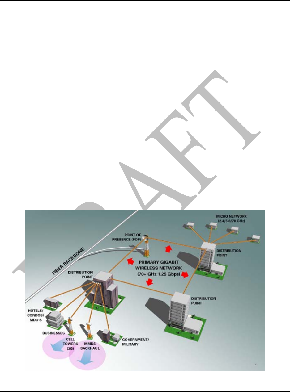
1.2 L1000 Common Applications and Features
The L1000 is a last mile access solution and a replacement for buried/aerial fiber cable such as
wireless backhaul, last mile access and LAN/WAN extensions.
The L1000 is rapidly deployable and re-commissionable making it an ideal solution for
temporary bandwidth or for emergency situations that could cause an interruption to buried
technologies.
In short, most applications of fiber cable in the last mile are potential applications for the L1000.
Figure 1. Typical L1000 Applications.
L1000 User’s Manual
DU1000-01 11/26/07
Loea Corporation
733 Bishop Street, Suite 1717
Honolulu, HI 96813
Phone: (808) 521-4908
Fax: (808) 521-4906
www.loeacom.com
7
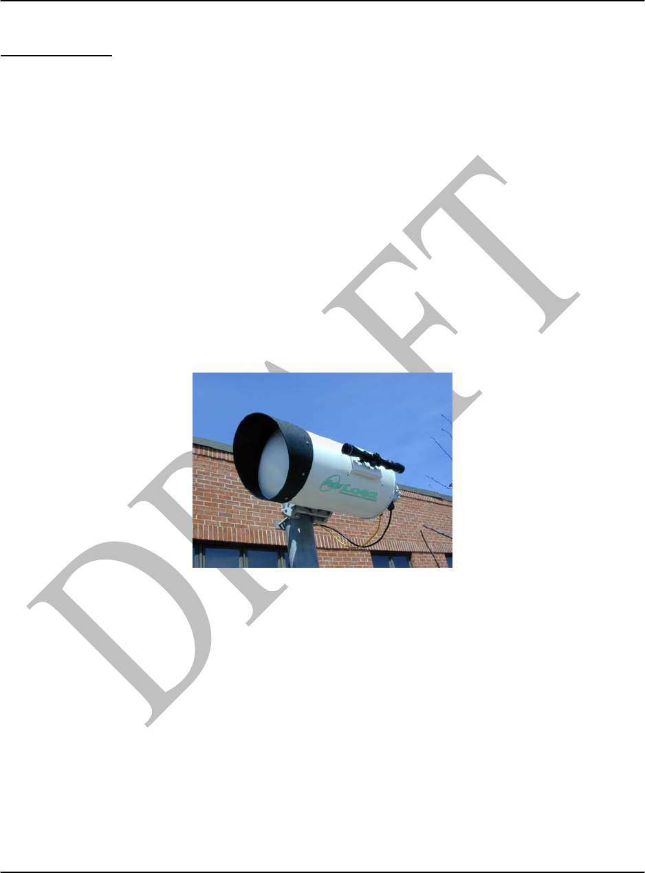
Product Features:
• Operation in the Part 101 licensed 71.0-76.0GHz & 81.0-86.0GHz band.
• FCC and NTIA certified
• Standard LC fiber optic interface
• -48 Volt telecom standard DC power
• 110V AC power, 50W peak consumption (option)
• 21dBm peak output power – OOK Modulation
• All weather performance
• OSI Layer 1 data transmission
o Interoperable with most fiber optic COTS switch, router and encryption devices.
o Plug and play with existing networks.
• Secure Transmission and narrow beam widths
o Low Probability Intercept and Low Probability Detection (LPILPD)
o Co-existence of many users with low likelihood of interference
• Operating Temperature from -30C to +55C
Figure 2. L1000 Mounted on 4” Mast
L1000 User’s Manual
DU1000-01 11/26/07
Loea Corporation
733 Bishop Street, Suite 1717
Honolulu, HI 96813
Phone: (808) 521-4908
Fax: (808) 521-4906
www.loeacom.com
8
2. Installation Procedures
2.1 Introduction
This manual provides basic instructions on the assembly, alignment and verification of the Loea
L1000 system. In doing so, it outlines recommended tools and processes to use. A detailed
understanding of this manual and participation in a Loea training class is highly recommended
prior to starting any work on site. Only Loea Trained and Certified installers should perform
installation services on the L1000.
Please note that every area of the country has its own codes of safety and construction.
Installations must comply with these codes. It is the installer/user’s responsibility to understand
what codes apply and to ensure that the installation conforms to these codes.
2.2 Standard Link Components
Description Part # Comments
Transceiver Pair L1000-WXYZ Radio Pair Only
Table 1 – Basic L1000 Components
Part Number Format
L100N – W X Y Z
W – Orientation
V = Vertical
H = Horizontal
X – Payload
C = MultiRate
OC12 (155MB) to 1.5GB/s
D = 3.072 GB/s
N – Terminal Config
0 = Complete link
7 = Tx at 73.5GHz
8 = Tx at 83.5GHz
Y – Optical Interface
S = 1310nm
M = 850nm
Z – Input Power
B = 110/220V AC w/ Demarc
D = -48V DC

L1000 User’s Manual
DU1000-01 11/26/07
Loea Corporation
733 Bishop Street, Suite 1717
Honolulu, HI 96813
Phone: (808) 521-4908
Fax: (808) 521-4906
www.loeacom.com
9
2.3 General Installation Requirements
Before the installation of a Loea link, certain steps must be taken to ensure that the installation
will be successful.
A. Site Survey: During a site survey a certified Loea surveyor can assess the
environment of the installation, ensure that the physical conditions of the site are
appropriate, indicate where building connections need to be available and ensure that
Line of Sight (LOS) exists between the two end points.
B. FCC Part 101 License: Loea’s band of operation is licensed by the FCC for non-
federal government users and by the NTIA for federal government and DOD users.
Prior to deployment, a license is required. For more information on obtaining a
license for operation of this radio in the 70 and 80 GHz bands see
http://wireless.fcc.gov/services/millimeterwave/ and select the “nationwide license”
link. There is an application form and information pertaining to current license fees
at this site. Please contact Loea directly with any questions.
C. Installation of Mast and Demarcation: A standard 2.5 in to 4in mast (4.5in O.D.
Max) must be installed at a position and specific height as specified in the Site
Survey. To facilitate connection to the building’s network; fiber for communications,
and Ethernet for monitoring are required in a demarcation box per the specifications
in this manual and specifically as defined in the Site Survey.
D. Bench Test: Loea recommends that the transceivers be tested after delivery to the site
and prior to installation on the mast to ensure that no damage occurred during
shipping and to familiarize the customer with radio operation. To perform a bench
test:
a) Separate the transceivers by approximately 5 feet on a wooden or non-metallic
surface. Align the radios so that the radios are in the same RF orientation (to do
this situate the radio housing so that the bore scope on each radio is on top) and
pointed directly at each other with absorber material on each lens. When user
can verify a valid RSSI (Receive Signal Strength Indicator) value a link has been
established. Then when BER performance is verified the link is functional. See
reference Sections 2.7, 2.8 and 2.9.
b) If possible, a complete end-to-end test is recommended with switching and/or
encryption devices. The L1000 is generally a plug and play device, it is
recommended to do this to avoid de-bugging in the field.
E. System Commissioning: Upon install completion, metrics from the install site must
be recorded and verified to ensure that the transceivers are performing as expected.
The “Loea Field Service Data” form (see Appendix A) should be forwarded to Loea
following the installation. This will assist Loea’s technical service and help desk
personnel assess problems should a link fail to operate. It is also recommended that
the end user/owner keep a copy for their records.
L1000 User’s Manual
DU1000-01 11/26/07
Loea Corporation
733 Bishop Street, Suite 1717
Honolulu, HI 96813
Phone: (808) 521-4908
Fax: (808) 521-4906
www.loeacom.com
10
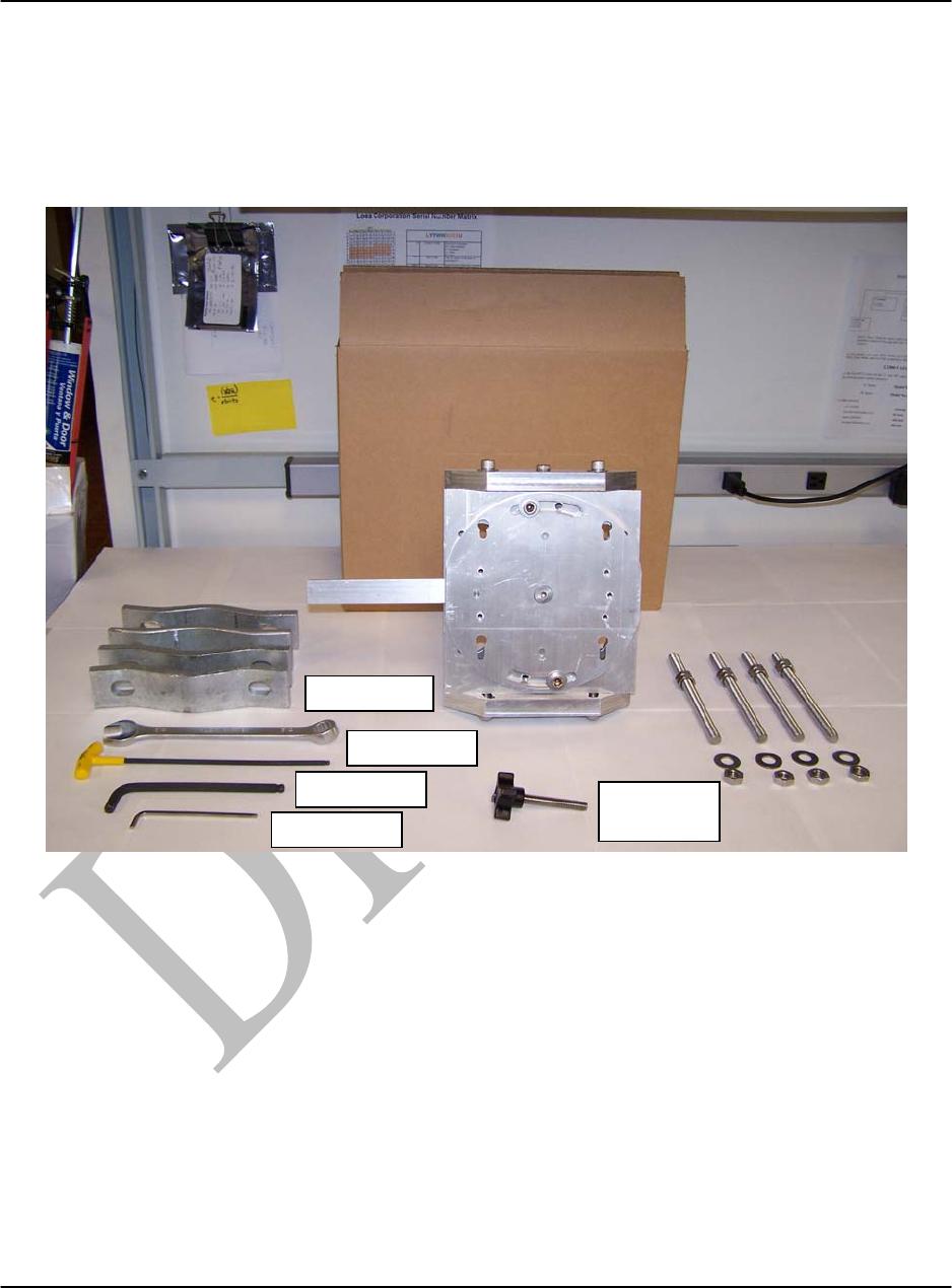
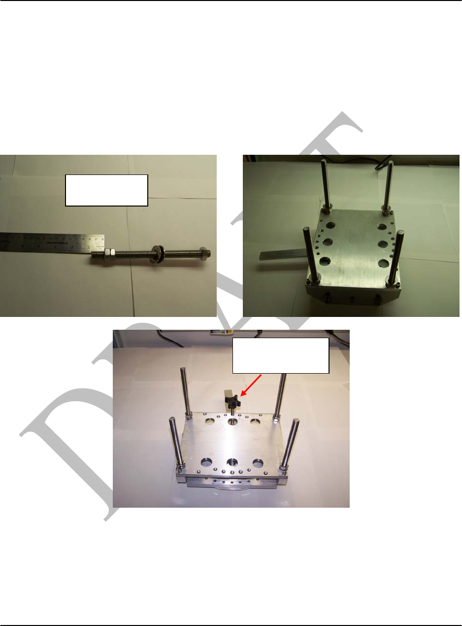
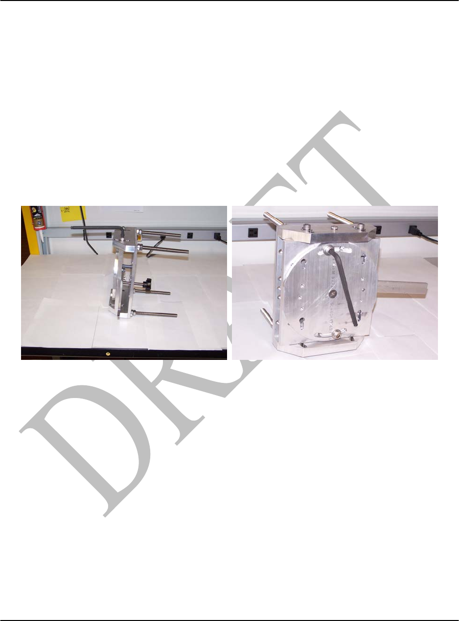
2.4 Steering/Mounting System (FS001000)
The photo below shows the components that comprise the Steering/Mounting mechanism. Also,
the tools required to assemble and install are included. The mount can be attached to mast
ranging in size from 2.5” to 4.5” O.D.
Figure 3. Steering/Mount Mechanism and tools.
¾
” Wrench
3/16” Allen
5/16” Allen
5/32” Allen Azimuth
Control
L1000 User’s Manual
DU1000-01 11/26/07
Loea Corporation
733 Bishop Street, Suite 1717
Honolulu, HI 96813
Phone: (808) 521-4908
Fax: (808) 521-4906
www.loeacom.com
11
2.4.1 Assemble Mount
The threaded rod should have two nuts on the end that is inserted into the mount plate. Make
sure that the nut closest to the mount plate is ¾” in from the end. Install the 4 rods into the
mount plate until the nut touches the plate. Do not continue turning the rod as the nut will not
stop the rod from continuing into the plate. Use the ¾” wrench to tighten the nut nearest the
plate. Lastly, install the Azimuth Control knob in the center hole of the semi-circular pattern of
threaded holes on the same side of the mount where the elevation control handle resides (as
shown in the photo below).
Figure 4. Mount Assembly
Backing Nut ¾”
from end of rod
Azimuth Control
Knob
L1000 User’s Manual
DU1000-01 11/26/07
Loea Corporation
733 Bishop Street, Suite 1717
Honolulu, HI 96813
Phone: (808) 521-4908
Fax: (808) 521-4906
www.loeacom.com
12
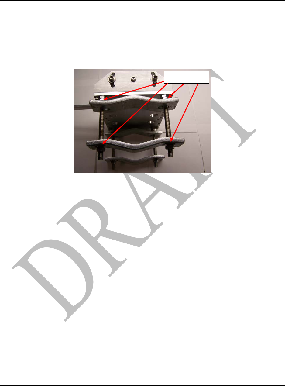
2.4.2 Attach the Mast Clamp Brackets
Each Steering/Mount mechanism kit contains 4 Mast Clamp Brackets. Be sure to install washers
(8) between the bracket and the nut as shown in the photo below. The photo below depicts the
washer placement for the top half of the mount. Repeat washer placement for the bottom half of
the mount. The mount is ready to be attached to the mast.
Figure 5. Assembly of Mount with Mast Clamp Brackets.
4 Washers
L1000 User’s Manual
DU1000-01 11/26/07
Loea Corporation
733 Bishop Street, Suite 1717
Honolulu, HI 96813
Phone: (808) 521-4908
Fax: (808) 521-4906
www.loeacom.com
13
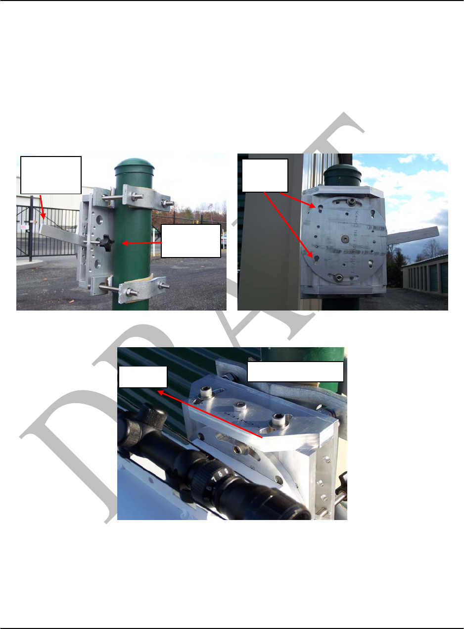
2.5 Attach Assembly to Mast (see Figure 6)
Remove the back brackets from the mount and then place mount on mast. Be sure that the Slot
holes for the radio our oriented downward. If the mount must go on the other side of the mast,
please refer to the Reverse Orientation section. Place the top bracket on the threaded rod and
then insert the washers and nuts. After securing the mount to the mast but prior to tightening the
brackets in place, perform a “gross” alignment by looking at the target and lining up the straight
edge on the mount so that the mount will be “pointing” towards the target (see photo below).
Figure 6. Attaching Assembly to Mast.
Figure 7. Use straight edge as a guide for Gross Alignment.
Once the steering assembly is grossly aligned, tighten the Mount Bracket nuts with a ¾” wrench.
The radio can now be attached to the mount.
Elevation
Control
Azimuth
Control
Aim towards target
Tar
g
et
Slots
Down
L1000 User’s Manual
DU1000-01 11/26/07
Loea Corporation
733 Bishop Street, Suite 1717
Honolulu, HI 96813
Phone: (808) 521-4908
Fax: (808) 521-4906
www.loeacom.com
14
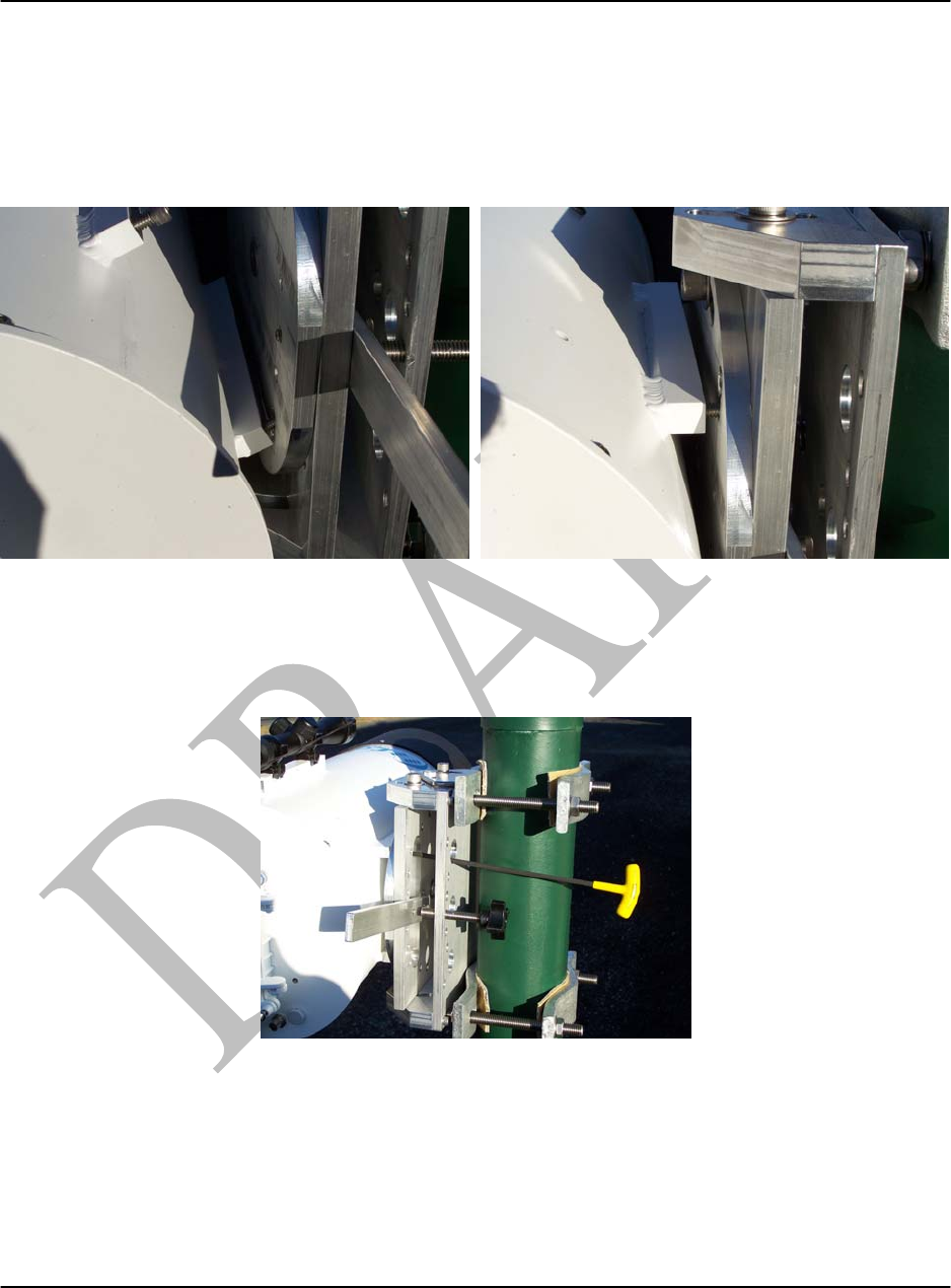
2.6 Attach Transceiver to Steering System (see Figure 8)
Once the steering assembly is secured to the mast per 2.5 above, the radio can be attached to the
mount. First, the radio should be tilted so that the screws on the bottom rail go through the
bottom slotted holes. Then tilt the radio upward to insert the top screws into the slotted holes.
Figure 8. Attaching Transceiver to Steering System.
Make sure the screws have seated in the slots securely before releasing the radio. Using the
3/16” T-handle wrench, tighten the screws. The radio is now ready for alignment.
Figure 9. Tighten radio mount screws with 3/16” Allen wrench.
L1000 User’s Manual
DU1000-01 11/26/07
Loea Corporation
733 Bishop Street, Suite 1717
Honolulu, HI 96813
Phone: (808) 521-4908
Fax: (808) 521-4906
www.loeacom.com
15
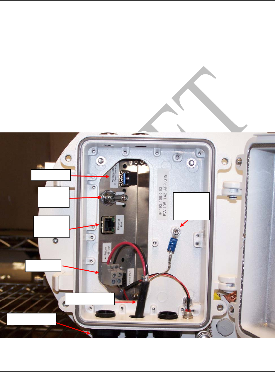
2.7 Cabling to the Radio (see Figure 10)
Before proceeding to the alignment of the link, the installer must complete the fiber, DC power
(if using AC power, DC power will come from the optional Demarc box) and Ethernet
connections to the radio. Typically this will be carried out by connecting the cables to the
housing and completing the connection inside the service compartment. It is recommended that
the power cable is Belden 9342 which is shielded. Add a terminal connector to the drain wire
(3M’s P/N MVU14-8R or similar #8 stud) and a 6-32 screw and lock washer. The Red wire
should be connected to the positive terminal of the 48VDC supply and the Black wire will be
connected to the Negative terminal on the 48VDC supply. The duplex LC terminated fiber cable
and Ethernet cable (for radio health monitoring) should be plumbed through crimp glands and
inserted into the appropriate ports.
Note: Do not over tighten the crimp glands.
Figure 10. Inside Radio Service Compartment
Fi
be
r P
o
rt
Ethernet
Port
ON/Off
Switch
-48VDC
Ground
Cable
Shiel
d
Belden 9342
Crim
p
Glands
L1000 User’s Manual
DU1000-01 11/26/07
Loea Corporation
733 Bishop Street, Suite 1717
Honolulu, HI 96813
Phone: (808) 521-4908
Fax: (808) 521-4906
www.loeacom.com
16
Begin by first passing the shielded DC power cord (Belden 9342) thru the cable crimp gland.
Once the power cord has been pulled thru, attach the + side of the 48V DC to the terminal closest
to the door hinge (Fig.10). Connect the drain wire to a solderless crimp connector and attach to
housing with a 6-32 screw (supplied).
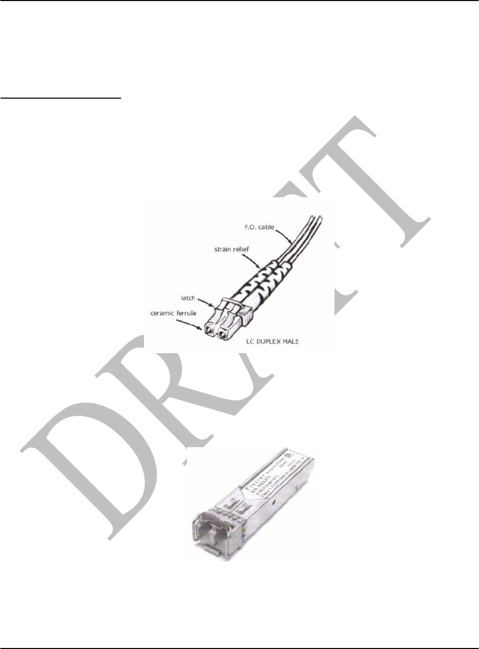
Fiber Signal interface: A duplex male LC terminated fiber optic connection is the standard
interface inside the L1000 radio. For applications using the Gigabit Ethernet standard, it is
recommended the customer use Single Mode 1310nm. Multimode 850nm fiber is available as an
option but is not recommended due to the limited temperature and distance performance of
Multimode fiber and related components. For the Sonet standards, it is required that the customer
use Single-mode 1310nm fiber.
A graphic showing the required LC fiber connector to be used is shown in Fig. 11.
Figure 11: Typical LC Duplex Male Connector
The fiber connector will mate with the SFP located in the service panel as shown in Fig.8. A
typical pluggable SFP is shown in Fig. 12. Do not attempt to remove the SFP unless instructed
to do so by a Loea engineer.
Figure 12: Typical Pluggable SFP
L1000 User’s Manual
DU1000-01 11/26/07
Loea Corporation
733 Bishop Street, Suite 1717
Honolulu, HI 96813
Phone: (808) 521-4908
Fax: (808) 521-4906
www.loeacom.com
17
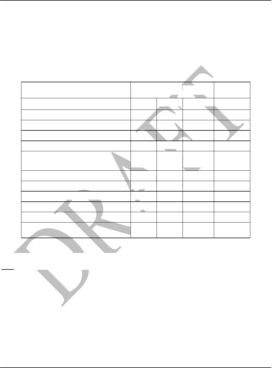
The optical interface specifications for the Single Mode SFP and Multimode SFP connections
are shown in Table 2a and 2b respectively.
Optical Specifications Min Typ Max Unit
Transmitter
Output Opt. Power -9.5 -3 dBm
Optical Wavelength 1270 1360 nm
Spectral Width 3 nm
Receiver
Average Rx Sensitivity @ 1.25 Gb/s
(Gigabit Ethernet)
-22
dBm
Average Received Power 0 dBm
Optical Center Wavelength 1265 1600 nm
General Specifications
Data Rate 1062
2125
Mb/sec
Bit Error Rate
10-12
Max. Supported Link Length on
9/125um SMF
@
Gi
g
abit Ethernet
10
Km 1
Table 2a: Single-mode Fiber Optic Interface Specification
Note
1. Attenuation of 0.55 dB/km is used for the link length calculations. Please refer to the Optical
Specifications above to calculate a more accurate link budget based on specific conditions in
your application and the L1000 User Manual prior to connecting to the network to ensure that
optical power is in the proper range based on the specifics of the installation.
L1000 User’s Manual
DU1000-01 11/26/07
Loea Corporation
733 Bishop Street, Suite 1717
Honolulu, HI 96813
Phone: (808) 521-4908
Fax: (808) 521-4906
www.loeacom.com
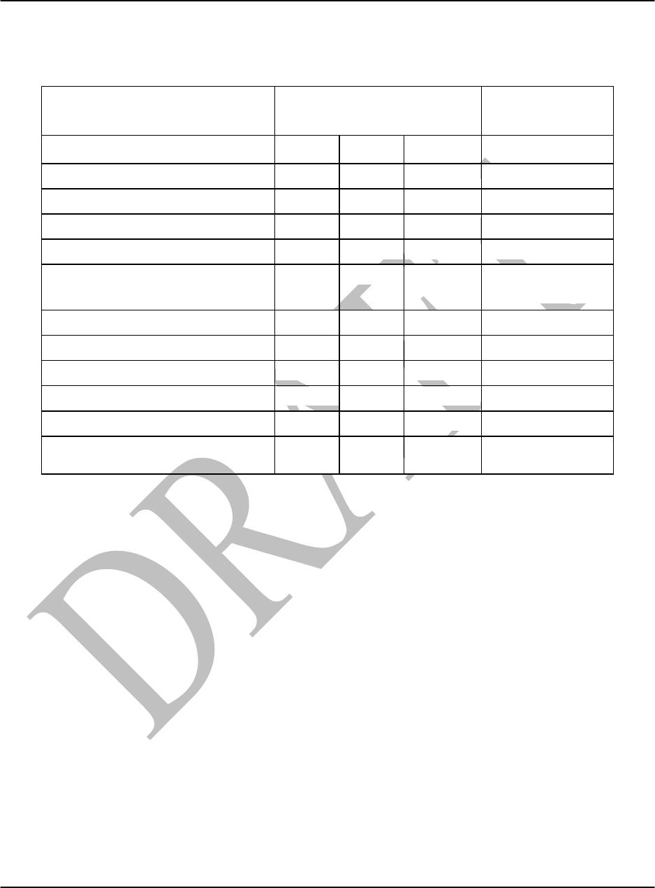
18
Optical Parameters Min Typ Max Unit
Transmitter
Output Opt. Power -9 -3 dBm
Optical Wavelength 830 860 nm
Spectral Width 0.85 nm
Receiver
Average Rx Sensitivity @ 1.0625
Gb/s
-22 -20 dBm
Average Received Power 0 dBm
Optical Center Wavelength 770 860 nm
General Parameters
Data Rate
1062
Mb/sec
Bit Error Rate
10-12
Note: PRBS 27-1
Max. Supported Link Length on
50/125um MMF
550
m
Table 2b: Multi-mode Fiber Optic Interface Specification
A demarcation box must be provided by the customer in accordance with a site survey which
must be conducted prior to any attempted installation. The demarcation box should be located
no further than 15’ away from the base of the radio installation or as specified in the site survey
report.
After all connections have been made the power switch located in the service compartment
should be turned ON. The ‘red’ LED located on the outside of the radio will turn on indicating
the unit has power. The user should wait a minimum of 10 minutes before making RSSI
measurements to allow the unit to warm up.
L1000 User’s Manual
DU1000-01 11/26/07
Loea Corporation
733 Bishop Street, Suite 1717
Honolulu, HI 96813
Phone: (808) 521-4908
Fax: (808) 521-4906
www.loeacom.com
19
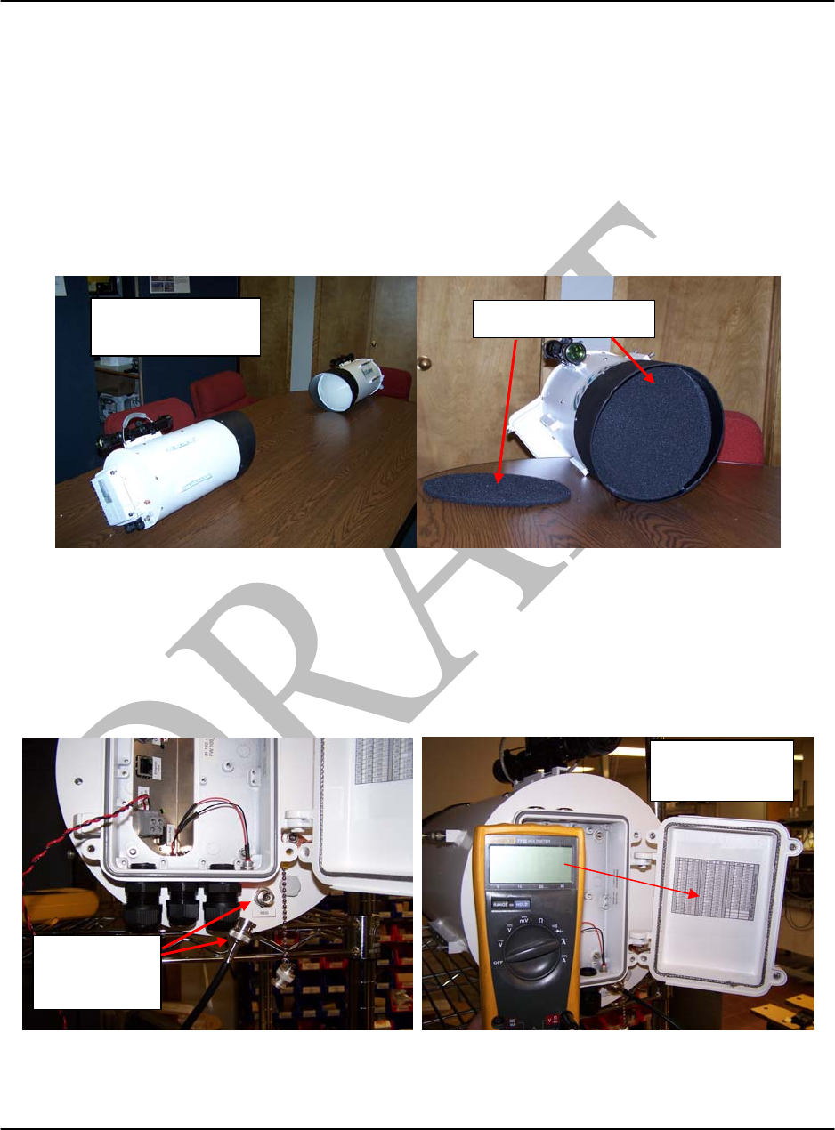
2.8 Bench Testing Radios
Often, it is helpful to bench test the link in a lab environment to ensure that the installer team is
familiar with the proper operation of the link before field commissioning. The radios should be
placed 5ft apart at the same height. A large bench could be used. The absorber disks should be
placed in front of each lens prior to powering the radios.
Figure 13. Bench Test Setup
The radios may need to be moved for proper alignment in order to each error free performance.
Check the RSSI level via the BNC connector to ensure that the radios are in a valid operating
range. Find the DMM DC voltage reading on the RSSI lookup table. Adjustments to the
alignment may be necessary to obtain a valid RSSI reading (should be 40 to 50dB).
Figure 14. RSSI Measurement
Absorber Dis
k
Setup without
Absorber
BNC
connection to
DMM &RSSI
2.504
RSSI lookup
Table
L1000 User’s Manual
DU1000-01 11/26/07
Loea Corporation
733 Bishop Street, Suite 1717
Honolulu, HI 96813
Phone: (808) 521-4908
Fax: (808) 521-4906
www.loeacom.com
20
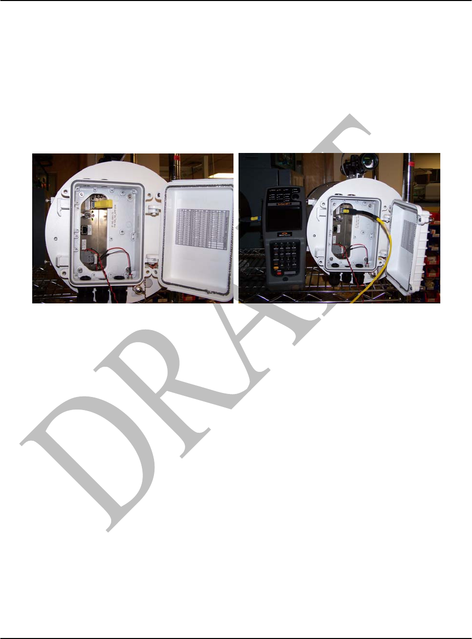
A fiber loop back should be installed into the SFP port of one radio and a BER tester should be
connected to the other radio. The BER tester should register zero errors.
Note: If the test environment has metal walls or desk very close to the product, results may not
be perfect. This is a rudimentary test to prove functionality NOT performance. Valid
performance tests are to be conducted after installation.
Figure 15. BER Test Connections
L1000 User’s Manual
DU1000-01 11/26/07
Loea Corporation
733 Bishop Street, Suite 1717
Honolulu, HI 96813
Phone: (808) 521-4908
Fax: (808) 521-4906
www.loeacom.com
21
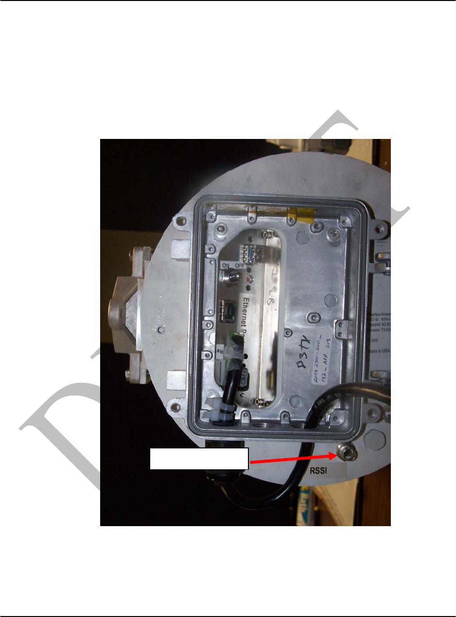
2.9 Interfacing to RSSI Port (see Figure 16)
The RSSI (Received Signal Strength Indicator) voltage is a measure of received signal strength
which will be used to assess alignment. To measure the RSSI voltage, locate the BNC connector
external to and below the service compartment (see Figure 14). Connect a Fluke DMM Series
77 or similar to the BNC connector and note the RSSI mV reading (a dual banana to BNC
connector can be used). The chart pasted to the flat surface inside the service compartment will
provide an indication of the correlation between mV and dB of link margin.
Figure 16. Radio Rear Cover Removed Showing Service Compartment.
For each RSSI mV reading there is an equivalent dB link margin reading. An example of the
Chart is shown in Figure 14. By fine-tuning the alignment, try to get the RSSI voltage within +/-
5dB of the link margin specified in your final proposal and/or site survey report provided by a
Loea certified engineer.
BNC Connector
L1000 User’s Manual
DU1000-01 11/26/07
Loea Corporation
733 Bishop Street, Suite 1717
Honolulu, HI 96813
Phone: (808) 521-4908
Fax: (808) 521-4906
www.loeacom.com
22
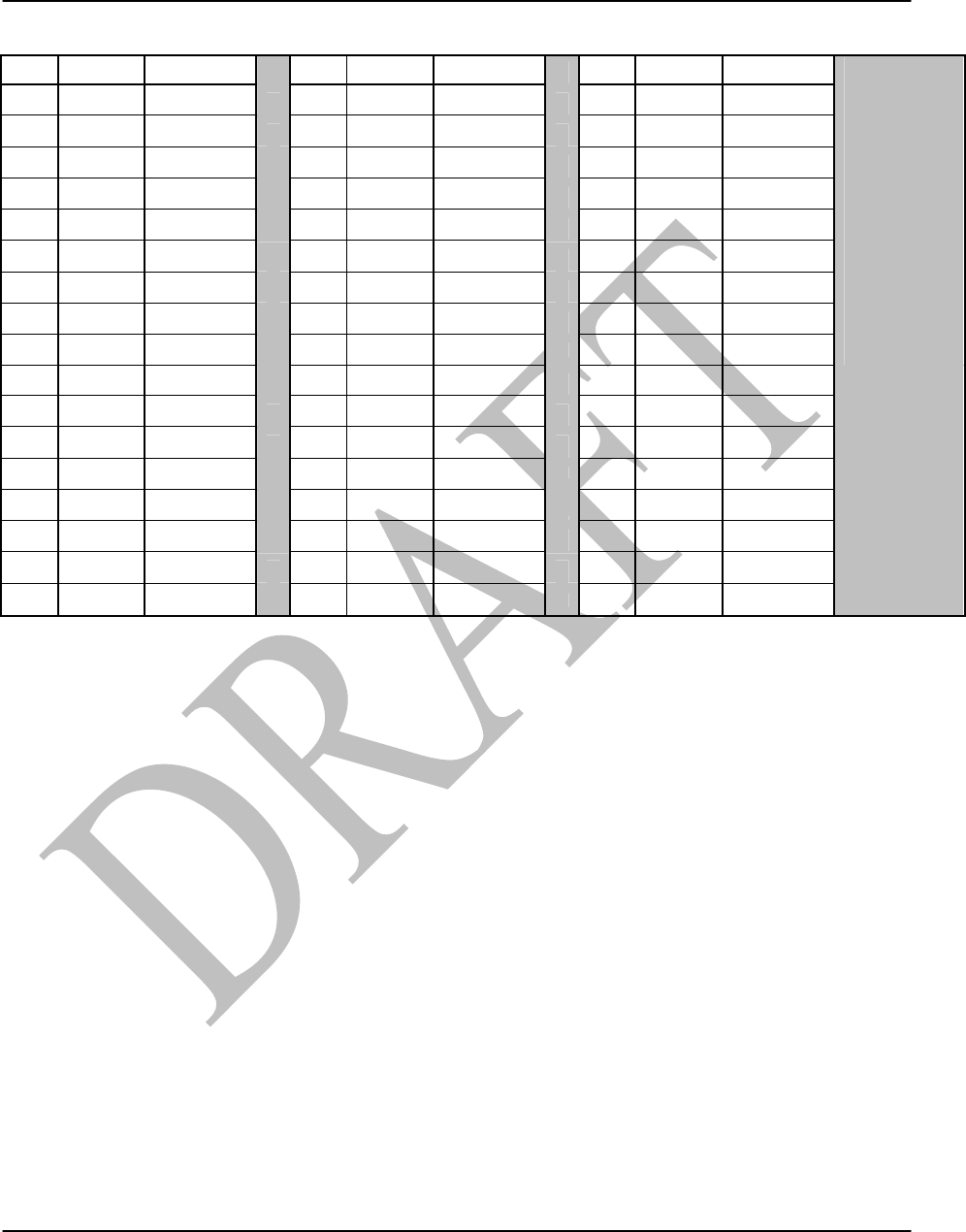
P/L RSSI BER P/L RSSI BER P/L RSSI BER
67 0.65 1.00E-11 50 2.45 1.00E-11
66 1.763 1.00E-11 49 2.465 1.00E-11
65 1.98 1.00E-11 48 2.478 1.00E-11
64 2.085 1.00E-11 47 2.492 1.00E-11
63 2.152 1.00E-11 46 2.505 1.00E-11
62 2.198 1.00E-11 45 2.517 1.00E-11
61 2.233 1.00E-11 44 2.527 1.00E-11
60 2.261 1.00E-11 43 2.537 1.00E-11
59 2.285 1.00E-11 42 2.546 1.00E-11
Serial Number:
58 2.307 1.00E-11 41 2.554 1.00E-11
74 0.226 1.00E-05 57 2.327 1.00E-11 40 2.561 1.00E-11
73 0.227 5.00E-08 56 2.345 1.00E-11 39 2.567 1.00E-11
72 0.228 1.00E-10 55 2.363 1.00E-11 38 2.573 1.00E-11
71 0.229 1.00E-11 54 2.381 1.00E-11 37 2.579 1.00E-11
70 0.231 1.00E-11 53 2.399 1.00E-11 36 2.584 1.00E-11
69 0.233 1.00E-11 52 2.417 1.00E-11 35 2.59 1.00E-11
68 0.237 1.00E-11 51 2.434 1.00E-11 34 2.596 1.00E-11
102
Figure 17. Typical RSSI Chart .
L1000 User’s Manual
DU1000-01 11/26/07
Loea Corporation
733 Bishop Street, Suite 1717
Honolulu, HI 96813
Phone: (808) 521-4908
Fax: (808) 521-4906
www.loeacom.com
23
2.10 Alignment Techniques (see Figure 18)
The alignment process for a Loea link is performed manually. The Loea steering assembly has
an elevation control lever and azimuth control knob along with a scope mounted on the top of the
radio for fine alignment.
General coarse alignment is achieved when attaching the mount to the mast and using the
straight edge of the mount to align with the target. Adjusting the azimuth to the right is achieved
by turning the azimuth control knob in a clock wise direction (for a left side orientation) and
counter clockwise to move the cross hairs left. Adjust azimuth until the cross hairs are on the
lens/target and then tighten the locking bolts with the 5/16” Allen wrench.
Figure 18. Alignment Technique.

L1000 User’s Manual
DU1000-01 11/26/07
Loea Corporation
733 Bishop Street, Suite 1717
Honolulu, HI 96813
Phone: (808) 521-4908
Fax: (808) 521-4906
www.loeacom.com
24
_________________________________________________
Figure 19. Antenna Pattern with Side Lobes.
Once coarse visual alignment is complete, use a Fluke Digital Multi-Meter (DMM) Series 77 or
similar and connect it to the RSSI port. Begin the peaking of the link by using the following
method:
Using the steering assembly to adjust the Azimuth and Elevation, the scope on the antenna to
track position visually and the RSSI reading to fine tune, sweep the dish slowly over a pre-
determined pattern. For example, begin with a coarse optical alignment slightly off to one side
and elevated. Sweep across the location where the RF path should be to the opposite side of the
expected RF beam and then come down slightly in Elevation, sweep back to the original side and
repeat. Look for a peak in the RSSI value and continue until RSSI is peaked on one end.
Apply the above peaking method in the following manner to the link:
• Peak radio at end A of link
• Repeat at end B of link
• Repeat again at end A of link
• Repeat at end B of link if necessary.
Once the installer is satisfied that the link has reach a peak level, each radio, one at a time,
should be adjusted one last time off the main beam roughly 1 full rotation clockwise and ant-
clockwise of the fine adjustment bars in the vertical and horizontal direction. If no greater peak
is found then it is likely that the alignment is optimal. Ensure the adjustment bars are locked in
place. Proceed to section 2.10.
Peak gain Side-lobes

L1000 User’s Manual
DU1000-01 11/26/07
Loea Corporation
733 Bishop Street, Suite 1717
Honolulu, HI 96813
Phone: (808) 521-4908
Fax: (808) 521-4906
www.loeacom.com
25
2.11 Verification of Bit Error Rate (BER)
Verification of Bit Error Rate (BER) is achieved by using a fiber optic line tester to validate the
L1000. Typical fiber line testers can verify the protocol (Gigabit Ethernet or OC-12 SONET),
bandwidth, and optical signal quality in addition to BER ensuring a properly working link. Using
a BER tester, the installer must verify that the TX optical power level from the network and radio
at each end of the link are within the GBIC specifications given in Table 2a and 2b. If the
measured values are found to exceed these levels the installer must call Loea or insert
appropriate optical attenuators to bring the optical levels back into specification prior to making
the final fiber optic connection. The installer must record these measurements in the fiber
information section of the “Loea Field Service Data” report given in Appendix A.
Loea installers use the Sunrise Model # Sunset MTT-C Chassis with module MTT-29B for
Gigabit Ethernet link testing. This includes 1310 patch cords and an optics container. For OC-12
links the Sunrise Model # SSOCx is recommended which provides DSO Drop and Insert, FT1
and a Data Storage Card.
2.12 Final System Commissioning
Run the BER test for 30 minutes. If the BER is approximately 10-10 and a RSSI reading within
and +/-5dB of the expected value in the Site Survey, the system is now ready to be integrated
into your network. After integration into the network the BER for the system should be greater
than 10-6. If this is not the case contact a Loea engineer.
Ensure that the back cover of the L1000 is fastened down and that the lock nuts on the Azimuth
and Elevation adjusters have been tightened. Finally, make sure the all cables have been secured
to the L1000 and that the demarcation box has been properly sealed.
Prior to leaving the site, please complete a copy of the “Field Service Data Report” found in
Appendix “A”, save a copy for yourself and send a copy to Loea.

L1000 User’s Manual
DU1000-01 11/26/07
Loea Corporation
733 Bishop Street, Suite 1717
Honolulu, HI 96813
Phone: (808) 521-4908
Fax: (808) 521-4906
www.loeacom.com
26
3. Systems Integration
3.1 Standard System Demarcation Box Requirements
The Loea L1000 Transceivers will be provided with standard cable connections for a
demarcation box. The demarcation box is the key interface between customer premise equipment
and the radio. In the cases of system repair and diagnostics, should a Loea system problem be
reported, it can be isolated from the user’s physical plant at this demarcation point to help isolate
the problem. The demarcation box will be installed prior to Loea system installation per the
requirements stated in the site survey and must provide the following connections:
• -48VDC Power is required via 16 – 18 AWG (Belden 9342)
• Fiber-optic connection (Communication Signal)
• RJ45- CAT5 10/100baseT Ethernet (SNMP interface).
• Enclosure is supplied with the system.
3.2 Basic Information on Loea Interface
The Loea transceiver operates at the Physical Layer (Layer 1) of the OSI network stack. Loea’s
system will appear to be a fiber cable.
The transceiver has three connections as follows:
1.) Signal interface: At the radio, an LC fiber optic connector is the standard interface.
Single Mode 1310nm is recommended for most applications. The L1000 has a
Multimode 850nm option which may be used in some cases; please consult Loea for
more information.
2.) Power interface: The Loea transceiver’s standard configuration requires a -48VDC
(nom) connection.
3.) An optional 110 Volt AC power supply is also available.
4.) The Ethernet connection is for Link monitoring. Because the transceiver can be
viewed as a network element, there is a standard RJ-45 connection for SNMP.v3
access.
The Loea system is OSI Layer 1 (physical layer) and it will interoperate with most commercial
off the shelf (COTS) switches, routers and encryption devices. For further information on tested
devices please contact Loea.

L1000 User’s Manual
DU1000-01 11/26/07
Loea Corporation
733 Bishop Street, Suite 1717
Honolulu, HI 96813
Phone: (808) 521-4908
Fax: (808) 521-4906
www.loeacom.com
27
3.3 Link Monitoring
The L1000 series operates SNMP v.3 (factory default) or SNMP v.1
3.3.1 Network Management System Operation
The L1000 radio links are configured, operated and monitored through the SNMP interface by
using a SNMP based Network Management System (NMS) and an SNMP agent in the L1000
radio. Each L1000 radio can send SNMP traps to the NMS over the RJ-45 Ethernet port located
on the back of each radio. At this time Loea does not have its own element manager application.
Workstation
The NMS workstation manages all L1000 uniquely assigned IP addresses. See Appendix C for
an example on how to install the L1000 MIB using an off-the-shelf NMS application. The
workstation also provides a graphical display of the network objects showing the status,
performance and configuration parameters. The SNMP interface also allows operators real-time
notification of radio problems.
Agent
The SNMP local agent is a standard MIB-II compliant software module that resides in each
L1000 radio. The agent collects information from different L1000 components internal to the
radio as defined in the Management Information Base (MIB) structure. The L1000 incorporates a
private MIB. See Appendix B for details of the L1000 MIB and the associated variable
descriptions.
3.3.2 NMS Data Transfer
The NMS data transfer between the manager (Workstation running the NMS application) and the
SNMP agents (Radios) is accomplished using either polling or trapping techniques.
Polling
The NMS polls each L1000 SNMP agent at specific intervals. These are set according to user
requirements during SNMP NMS configuration.

L1000 User’s Manual
DU1000-01 11/26/07
Loea Corporation
733 Bishop Street, Suite 1717
Honolulu, HI 96813
Phone: (808) 521-4908
Fax: (808) 521-4906
www.loeacom.com
28
Traps
The L1000 agent sends an SNMP trap to the manager whenever a predefined event occurs.
Groups of traps can be defined according to their level of severity. The operator can choose to
enable or disable any traps or group of traps according to their level of severity (and his or her
own security level).
3.4 RS-232 Serial Link Interface
The RS-232 interface provides an access port for a craft terminal used by installation or
maintenance personnel.
The RS-232 port is located in the service compartment of the radio (See Figure 8). A laptop
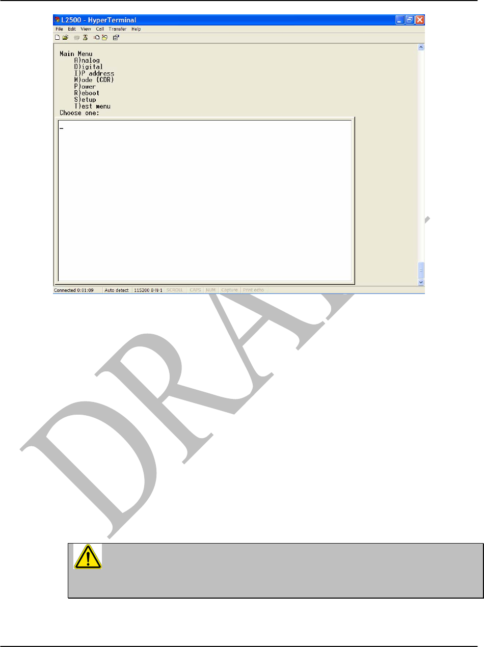
computer running HyperTerminal communicates with the radio via ASCII commands. The RS-
232 port offers different menu options to locally configure the radio.
After connecting a laptop PC to the RS-232 port on the radio, press ‘ENTER’ on the PC
keyboard and the screen in Figure 16 will appear showing the Main Menu. From this menu only
two of the options will be available to the end user. They are option I and S. These two options
will enable the following to be performed by the end user:
a) Set or Read IP address
b) Set or Read SNMP v1 ON or OFF
c) Set Read community string
d) Set Write community string
The rest of the options in the Main Menu (A, D, M, P, R and T) are reserved for the exclusive
use of those certified to perform field diagnostics.
THIS PORT SHOULD ONLY BE USED BY A CERTIFIED LOEA TECHNICIAN,
AND ANY UNAUTHORIZED USE OF THE RS232 CRAFT TERMINAL WILL VOID
THE WARRANTY.
L1000 User’s Manual
DU1000-01 11/26/07
Loea Corporation
733 Bishop Street, Suite 1717
Honolulu, HI 96813
Phone: (808) 521-4908
Fax: (808) 521-4906
www.loeacom.com
29
Figure 18. Main Menu as shown in (Windows) HyperTerminal.
Note that commands appearing in the white background pane reflect the active window. The
commands in the beige background flow from the active window (white background) and are
historical.
THIS PORT SHOULD ONLY BE USED BY A CERTIFIED LOEA TECHNICIAN,
AND ANY UNAUTHORIZED USE OF THE RS232 CRAFT TERMINAL MAY VOID
THE WARRANTY.
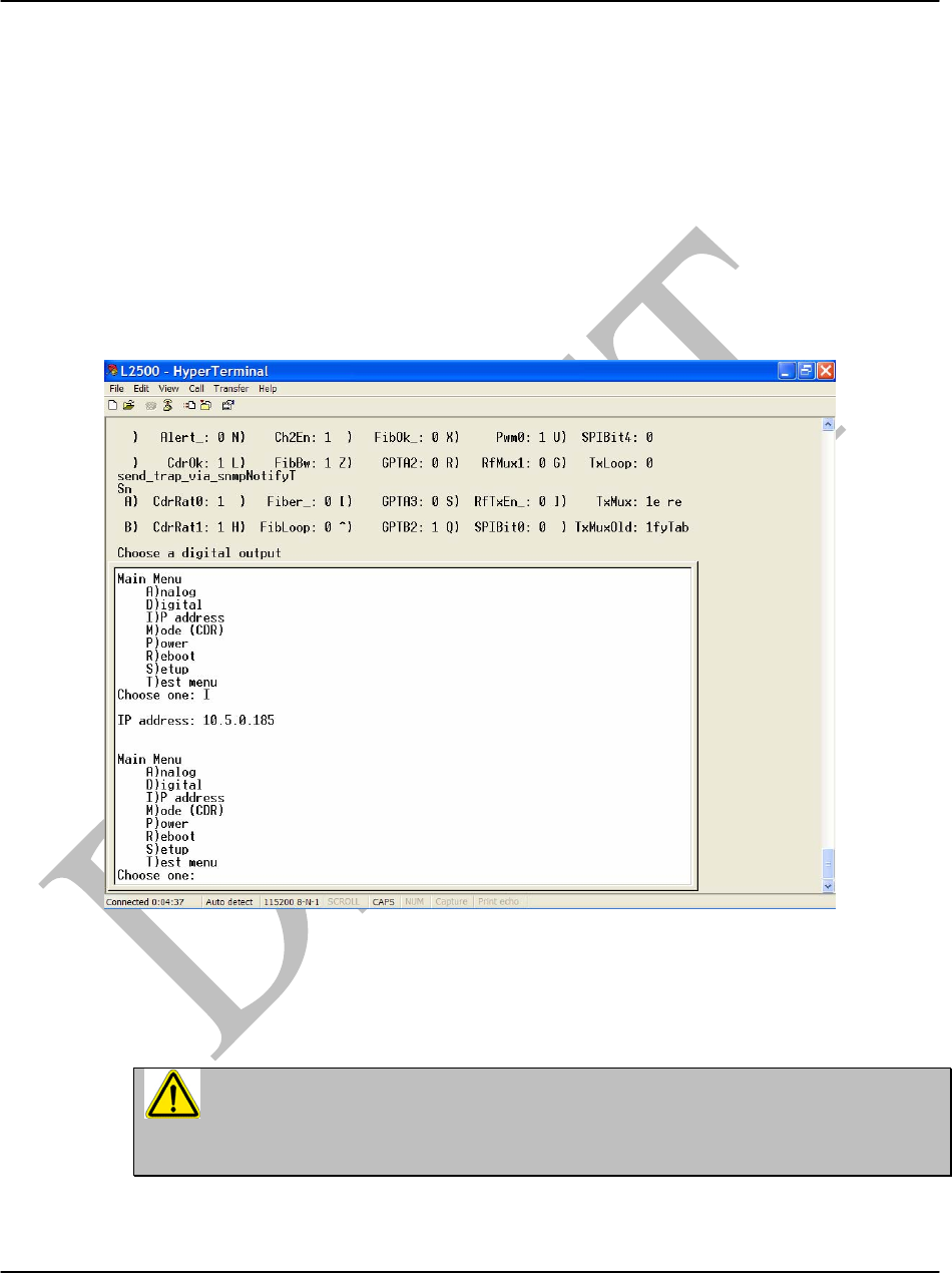
Option I:
L1000 User’s Manual
DU1000-01 11/26/07
Loea Corporation
733 Bishop Street, Suite 1717
Honolulu, HI 96813
Phone: (808) 521-4908
Fax: (808) 521-4906
www.loeacom.com
30
Selecting this option allows one to Set or Read the IP address for the radio (Figure 19). To Set
the IP address perform the following steps:
i) Reboot the NetBurner, by cycling power off and on
ii) Within 2 seconds, press A (capital A)
iii) Type ‘setup’
iv) Press 1, then Enter
v) Enter the new IP address
vi) Press s, then Enter
vii)Answer y to the question
viii) The NetBurner will reboot with the new address …………………..
Figure 19 Main Menu option I shows IP address for radio.
THIS PORT SHOULD ONLY BE USED BY A CERTIFIED LOEA TECHNICIAN,
AND ANY UNAUTHORIZED USE OF THE RS232 CRAFT TERMINAL MAY VOID
THE WARRANTY.
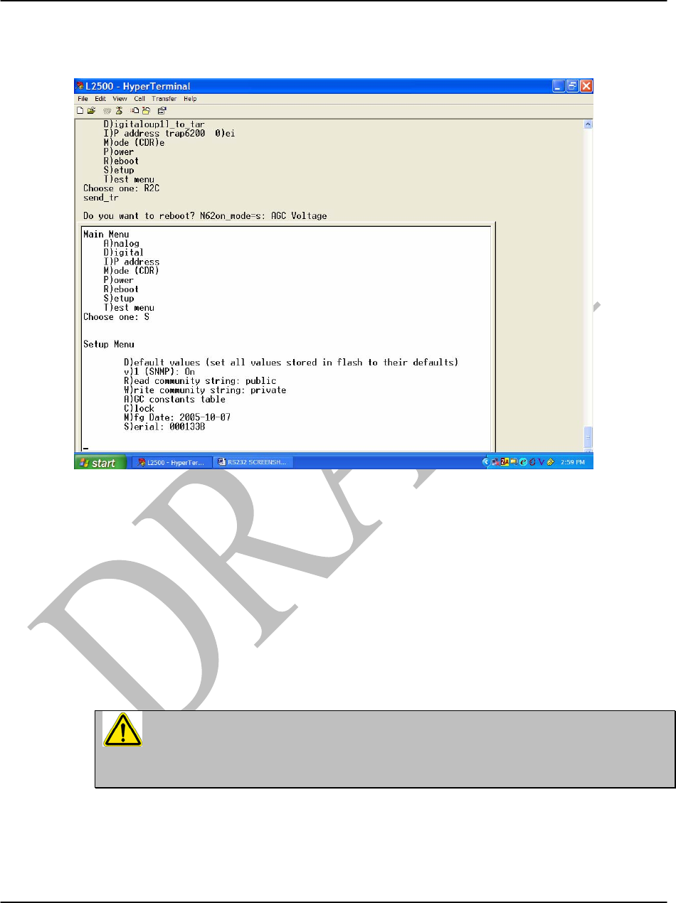
Option S:
L1000 User’s Manual
DU1000-01 11/26/07
Loea Corporation
733 Bishop Street, Suite 1717
Honolulu, HI 96813
Phone: (808) 521-4908
Fax: (808) 521-4906
www.loeacom.com
31
Selecting this option brings up the Setup Menu (Figure 20). Only the v), R) and W) options can
be modified by the end user.
Figure 20. Main Menu option S with Setup Menu options.
Selecting Setup Menu option:
V)Toggles the SNMP version 1) between ON or OFF. If toggled OFF then SNMP v3 is
configured and a password will need to be entered.
R) Sets the read community string.
W) Sets the write community string.
THIS PORT SHOULD ONLY BE USED BY A CERTIFIED LOEA TECHNICIAN,
AND ANY UNAUTHORIZED USE OF THE RS232 CRAFT TERMINAL WILL VOID
THE WARRANTY.

L1000 User’s Manual
DU1000-01 11/26/07
Loea Corporation
733 Bishop Street, Suite 1717
Honolulu, HI 96813
Phone: (808) 521-4908
Fax: (808) 521-4906
www.loeacom.com
32
3.5 Grounding Procedures
3.5.1 Single Point Grounding
The majority of surge arrestor devices are installed in shunt between the line and ground, which
can be either an earth ground or the power line neutral, which is in turn connected to ground.
Thus, the quality of the ground connection is as important as the surge arrestor itself, which can
only operate if it has someplace to send the surge. Equally as important as the quality of the
ground connection is the topology of the connection itself.
Most system installations have many pieces of interconnected equipment, all of which require
grounding. If each device has a different path to earth ground, voltage differentials will develop
between these grounds, and currents will flow between them resulting in Electromagnetic field
across Transmitting device. In the event of a high rise-time surge, the currents tend to act in a
conductor more like AC than DC. The currents will oscillate inside a conductor as damped wave
at a frequency in the RF region. Further, it results in harmonics and Electromagnetic
Interference.
There are three methods generally accepted to reduce the inductance and equalize ground
voltages in a system installation:
1. Make all connections to ground as short and straight as possible, to reduce the inductance to a
minimum.
2. Use large cross-section conductors to maximize the current carrying capacity in consideration
of the skin effect, such as copper strap or large cross-section multiple-strand cables.
3. Use a single point grounding system to avoid circulating currents caused by multiple ground
connections.
This last point requires more explanation.
If a piece of equipment is grounded at more than one location, utilizing different paths that
eventually connect to earth ground, differences in potential may develop between the two
connections for the reasons just discussed. These grounds will attempt to equalize themselves,
resulting in a current passing through the equipment itself. Further, standing waves can be
established in the loop formed between the two pieces of equipment, their connections and the
ground itself, resulting in circulating currents which can damage the equipment or impede its
proper operation.
In a single point ground system, only one ground reference is established in a system, which is
well bonded to an earth ground.
L1000 User’s Manual
DU1000-01 11/26/07
Loea Corporation
733 Bishop Street, Suite 1717
Honolulu, HI 96813
Phone: (808) 521-4908
Fax: (808) 521-4906
www.loeacom.com
33
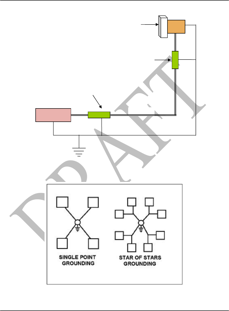
Figure 21. Single point grounding
The single point ground is an important part of reducing noise generated by RF via the grounding
system or return line.
Figure 22. Two Methods of Single Point Grounding
Antenna
Coax
RF Protector
TxRx
POP
Grounding
Demarcation
RF Protector

L1000 User’s Manual
DU1000-01 11/26/07
Loea Corporation
733 Bishop Street, Suite 1717
Honolulu, HI 96813
Phone: (808) 521-4908
Fax: (808) 521-4906
www.loeacom.com
34
All ground connections branch out from here so that there is only one ground path for each piece
of equipment. This method eliminates the possibility of ground loops and equalizes the ground
voltage differentials within the system. The single point ground system is also sometimes
referred to as a “star” grounding system. Larger systems can be connected using what is called a
“star of stars” system.
Even if a piece of equipment has been protected by a surge arrestor and is connected to a proper
earth ground, the problem is only partially solved. Presuming that the equipment the arrestor is
protecting is also grounded, not all the surge current will flow through the arrestor – some of the
current will still pass to ground by means of the other path going through the equipment. If we
want to maximize the current flow through the surge arrestor and minimize the current through
the equipment, we do this by lowering the inductance of the path through the arrestor as much as
possible.
3.5.2 Rack Cabinet Grounding
The single point grounding technique can also be effective to protect multiple pieces of
equipment installed inside an equipment rack cabinet. Treat the rack the same as you would a
building, and mount a panel on the cabinet to act as both an entrance panel and reference ground
for all conductors entering and leaving the rack. Install AC surge protectors at this point in shunt
to ground, and install series impedance between the panel and the equipment. Don’t count on the
metal cabinet itself to serve as a ground conductor – paint and oxidation may conspire to prevent
a good connection. A copper strap should be run along the inside of the cabinet, bonded to the
cabinet along its length, and also bonded to the access panel. The chassis of each piece of
equipment is then bonded to this buss bar with a single copper braid or strap. Finally, connect the
rack’s access panel to the building reference ground.
L1000 User’s Manual
DU1000-01 11/26/07
Loea Corporation
733 Bishop Street, Suite 1717
Honolulu, HI 96813
Phone: (808) 521-4908
Fax: (808) 521-4906
www.loeacom.com
35
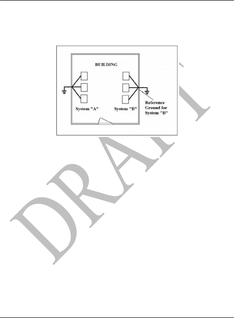
3.5.3 An Effective Earth Ground
Once all connections have been made to the master ground point in the building, it
must be bonded to an effective earth ground system outside the building.
Figure 23. Earth Ground
Four inch or larger copper strap is recommended, with short, straight connections. Corrosion will
dramatically increase the resistance of a connection; so use silver soldering or cad welding for all
connections exposed to the weather.
L1000 User’s Manual
DU1000-01 11/26/07
Loea Corporation
733 Bishop Street, Suite 1717
Honolulu, HI 96813
Phone: (808) 521-4908
Fax: (808) 521-4906
www.loeacom.com
36
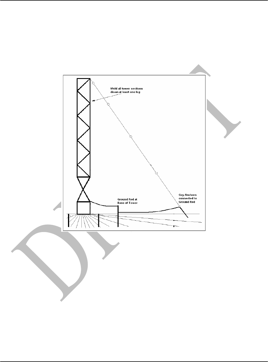
3.5.4 At the Tower
The following are some of the important steps to be taken at the base of a tower to maximize
protection against a lightning strike:
1. Tack weld all tower sections together running down at least at one leg, to provide corrosion
free electrical continuity to ground.
Figure 24. Tower Ground
2. Drive four or more ground rods at ten-foot intervals around the base of the tower, and ground
these to the tower.
3. Connect all the guy wire anchors to the Ground with a short jumper cable.
4. Use 16 AWG minimum and 6 AWG maximum insulated copper conductor. Typically, 10
AWG is the nominal size used in most installations.
5. National Electric Code (NEC) Chapter 8 on "Communication Systems" covers
general requirements for grounding, bonding and protection of low-voltage
communications equipment.

L1000 User’s Manual
DU1000-01 11/26/07
Loea Corporation
733 Bishop Street, Suite 1717
Honolulu, HI 96813
Phone: (808) 521-4908
Fax: (808) 521-4906
www.loeacom.com
37
3.5.5 Conclusion
Unpredictable and intermittent data loss and outright system failure can result from a transient.
To help ensure the safety and operation of sensitive telecommunications equipment, as well as
the safety of personnel. The electrical contractor should install an effective grounding system
that will circumvent such disturbances. To ensure effective equalization, the
telecommunications ground should be directly attached to the electrical service ground.
However, an electrode such as a ground rod or other grounding electrode system can be used
when no electrical service is present.
This article offers a brief explanation of how to install a telecommunications grounding system.
To help better understand the schematics of telecommunications grounding, consult
ANSI/EIA/TIA 607 that covers grounding and bonding requirements for telecommunications
applications in commercial buildings. Other important standards to consider include EIA/TIA
568-A and 569-A, which, as a set, are Telecommunications Building Wiring Standards. In
addition, the National Electric Code (NEC) Chapter 8 on "Communication Systems" covers
general requirements for grounding, bonding and protection of low-voltage communications
equipment. Chapter 2 and Article 250 discuss grounding requirements. The Canadian Electrical
Code (CEC) and other national and local safety codes also should be consulted where applicable.

L1000 User’s Manual
DU1000-01 11/26/07
Loea Corporation
733 Bishop Street, Suite 1717
Honolulu, HI 96813
Phone: (808) 521-4908
Fax: (808) 521-4906
www.loeacom.com
38
This page intentionally left blank
L1000 User’s Manual
DU1000-01 11/26/07
Loea Corporation
733 Bishop Street, Suite 1717
Honolulu, HI 96813
Phone: (808) 521-4908
Fax: (808) 521-4906
www.loeacom.com
39
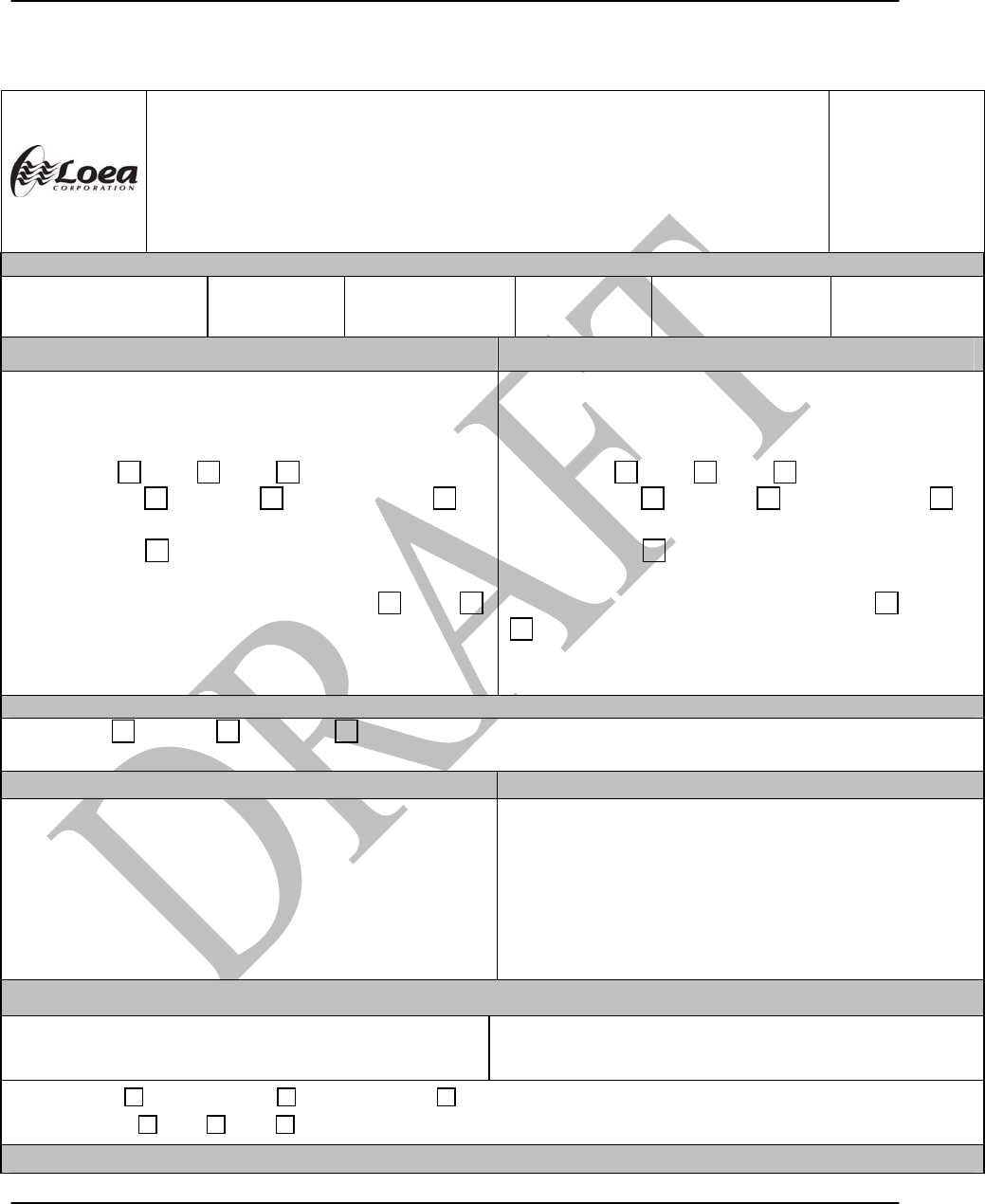
Appendix A - Field Service Form
Loea Field Service Data Page: 1 of 1
To be filled by the Field Service Engineer
Product: Link Serial #: Date of Service: Servive Type: Customer: Charge #:
B Radio A Radio
Location:
Lattitude:
GPS Coordinates:
Altitude:
Antenna: 4ft 2ft Other:
Mast Type: Tripod Wall Mount
Tower:
Other:
Height Off Ground:
Extension Beyond Highest Point: No
Yes: ____ft
Location:
Lattitude:
GPS Coordinates:
Altitude:
Antenna: 4ft 2ft Other:
Mast Type: Tripod Wall Mount
Tower:
Other:
Height Off Ground:
Extension Beyond Highest Point: No
Yes: ____ft
Link Information
Standard: GigE OC-12 Other:
Link Distance (km):
B Radio A Radio
IP Address:
Path Loss (dB):
RSSI (mV) Estimated:
RSSI (mV) Actual:
BER Bench:
BER Field:
IP Address:
Path Loss (dB):
RSSI (mV) Estimated:
RSSI (mV) Actual:
BER Bench:
BER Field:
Fiber Information
Fiber Tx Power from B Radio: …………….. dBm
Fiber Tx Power from Network (B side):…………dBm
Fiber Tx Power from A Radio: …………….. dBm
Fiber Tx Power from Network (A side): …………dBm
Fiber Type: 850nm (MM) 1310nm (SM) Other:
Termination: LC SC Other:
Input Power

L1000 User’s Manual
DU1000-01 11/26/07
Loea Corporation
733 Bishop Street, Suite 1717
Honolulu, HI 96813
Phone: (808) 521-4908
Fax: (808) 521-4906
www.loeacom.com
40
Distance to DEMARC:
Protection: Surge Conditioner UPS None
Conditions
Tem
p
erature: Relative Humidit
y
Wind Direction: Wind Speed:
Atomspheric Cnditions Clear Rain Snow Fog

L1000 User’s Manual
DU1000-01 11/26/07
Loea Corporation
733 Bishop Street, Suite 1717
Honolulu, HI 96813
Phone: (808) 521-4908
Fax: (808) 521-4906
www.loeacom.com
41
Appendix B – List of SNMP MIB Groups
Glossary
In this Appendix the following terms are used with these specific meanings:
SNMP - Simple Network Monitoring Protocol.
Radio - L1000 series radio
NMS - Network Monitoring Station. (Computer/software application for monitoring).
MIB - Management Information Base (SNMP variables applicable to the L1000)
OID - Object Identifier
Types of SNMP Operations
SNMP information can be described as:
• Query/response: Where the NMS sends a query to the radio, and the radio
responds with the appropriate information.
• Trap: Where the radio reports a threshold exception to the NMS.
MIB
The L1000 supports MIB-II, as well as variables specific to each radio model. There are three
MIB-II variables
Name Type Access Description
sysContact String (0..255) Read only Name of person to contact about this radio
sysName String (0..255) Read only Name of the radio – this is usually the fully
qualified domain name for this radio
sysLocation String (0..255) Read only Location of this radio
The radio-specific SNMP variables are divided into groups. Each group represents one type of
variable.
The OID of each radio-specific group starts with 1.3.6.1.4.1.1.11095.1.1. The OID column in
each table below contains the final two integers in the full OID for that variable.
System Group (lcSysGroup)
Contains information that identifies the radio:
Name OID Type Access Description
lcSysModel .1.1 String (0..5) Read only Radio model number, L1000
lcSysSerial .1.2 String (0..6) Read only Serial number
lcSysMfgDate .1.3 String (0..9) Read only Date of manufactured, YYYY-MM-DD
lcSysVer .1.4 String (0..5) Read only Firmware version

L1000 User’s Manual
DU1000-01 11/26/07
Loea Corporation
733 Bishop Street, Suite 1717
Honolulu, HI 96813
Phone: (808) 521-4908
Fax: (808) 521-4906
www.loeacom.com
42
Internal Group (lcIntGroup)
Contains information pertaining to the health of the radio, including voltages and currents:
Name OID Type Access Description
lcInt5V .2.1 Integer Read only Voltage of 5V supply, in mV
lcInt33V .2.2 Integer Read only Voltage of 3.3V supply, in mV
lcIntTemp .2.3 Integer Read only Temperature of radio, °C
lcInt5AP .2.4 Integer Read only Current of 5V supply to Power Amp, in
mA
lcInt5AF .2.5 Integer Read only Current of 5V supply to other boards, in
mA
Fiber Group (lcFibGroup)
Contains information that pertains to the fiber link:
Name OID Type Access Description
lcFibSFPPresent .3.1 Integer Read only 1 = SFP module is installed
lcFibSignalPresent .3.2 Integer Read only 1 = fiber signal detected
lcFibSignalStrength .3.3 Integer Read only If SFP module supports digital diagnostics,
and a fiber signal is detected, this is fiber
signal strength, in dBm, otherwise -100
lcFibCDRLock .3.4 Integer Read only 1 = Fiber CDR locked
lcFibDataRate .3.5 Integer Read only If rate is manually set, or if automatic and a
rate has been detected, this is that rate in
MBPS, otherwise 0
lcFibTxOn .3.6 Integer Read only 1 = Fiber transmitter on
RF Group (lcRFGroup)
Contains information that pertains to the RF link:
Name OID Type Access Description
lcRFAGCV .4.1 Integer Read only RSSI voltage, in mV
lcRFPathLoss .4.2 Integer Read only Path loss implied by RSSI voltage, in
dB
Trap Control Group (lcTCGroup)
This group defines the thresholds and other controls which are used to control traps. For each
analog signal, there is an enable control, a high value, and a low value. If the enable is set to 0,
this signal is ignored. If enable is set to 1, then this analog signal is compared to both the high
and low values. If it is goes from inside a range to outside, or from outside the range to inside,
the corresponding trap is generated. For each digital signal, a trap is generated each time that
signal changes state.

L1000 User’s Manual
DU1000-01 11/26/07
Loea Corporation
733 Bishop Street, Suite 1717
Honolulu, HI 96813
Phone: (808) 521-4908
Fax: (808) 521-4906
www.loeacom.com
43
Name OID Type Access Description
lcTCDestination .5.1 IP addr Read only Address to which traps are sent (if 0.0.0.0,
no traps are sent)
lcTCAliveInterval .5.2 Integer Read-write Interval in seconds between sending
lcTrapAlive
lcTCFiber .5.3 Integer Read-write Fiber signal strength trap enable
lcTCFiberHi .5.4 Integer Read-write High limit of fiber signal strength, in dBm
lcTCFiberLo .5.5 Integer Read-write Low limit of fiber signal strength
lcTCPathLoss .5.6 Integer Read-write Path loss trap enable
lcTCPathLossHi .5.7 Integer Read-write High limit of path loss, in dB
lcTCPathLossLo .5.8 Integer Read-write Low limit of path loss
lcTCTemp .5.9 Integer Read-write Temperature trap enable
lcTCTempHi .5.10 Integer Read-write High limit of temperature, °C
lcTCTempLo .5.11 Integer Read-write Low limit of temperature, °C
Traps
This table defines the traps that can be sent by the radio.
Name ID Description
lcTrapAlive 1 Sent every lcTCInterval seconds, unless lcTCInterval = 0
lcTrapFiberSignalNotOK 2 Sent when fiber signal strength is out of range
lcTrapFiberSignalOK 3 Sent when fiber signal strength is in range
lcTrapPathLossNotOK 4 Sent when path loss is out of range
lcTrapPathLossOK 5 Sent when path loss is in range
lcTrapTempNotOK 6 Sent when temperature is out of range
lcTrapTempOK 7 Sent when temperature is in range
SNMP v1/v3
The two versions of SNMP supported by the Loea radios are SNMPv1 and SNMPv3 (factory
default). SNMPv1 is not secure, because its community strings (passwords) are sent in clear
text. Anyone who has access to your network can discover SNMPv1 passwords, and therefore
they can monitor the radio. It is recommended that SNMPv1 not be used in any situation where
unauthorized individuals are able to access the network, such as over the Internet.
As shipped, the Loea radios have SNMPv3 enabled and SNMPv1 disabled. SNMPv1 can be
enabled by issuing the appropriate commands through the radio’s serial port. (See Section 3.4)
Unlike some devices which offer multiple views of the data for different purposes, the Loea
radios only have one view of all SNMP variables – anyone who has access to any SNMP
functionality has access to all of it.

L1000 User’s Manual
DU1000-01 11/26/07
Loea Corporation
733 Bishop Street, Suite 1717
Honolulu, HI 96813
Phone: (808) 521-4908
Fax: (808) 521-4906
www.loeacom.com
44
Appendix C –Example of Installing the L1000 MIB
This example is based the NMS application SNMPc. Please consult directions in your NMS
manual, contact your NMS supplier or contact Loea for assistance.
Begin by installing the SNMPc7 software on a workstation PC. Follow the instructions in the
“Getting Started” manual that comes with the software. Once the software has been installed,
integrate the L1000 MIB file with the SNMPc program by carrying out the following steps:
a) First locate the other MIB files used by SNMPc on the workstation PC. They should be at:
C:\Program Files\SNMPc Network Manager\mibfiles.
b) Copy the current version of the Loea 1000 MIB file to the same MIB folder.
c) On the SNMPc main menu, choose ‘Config’ then ‘mib database’, then click ‘Add’. Scroll
down to the end of the list – the Loea 1000 MIB should be there.
d) Select it and click ‘Ok’. Then click ‘Compile’ and after compilation is finished click ‘Done’.
At this stage the Loea 1000 MIB should be integrated with SNMPc7.
e) Now add the radios in each link to the list of monitored items. Refer to the ‘Getting Started’
manual on how to do this.
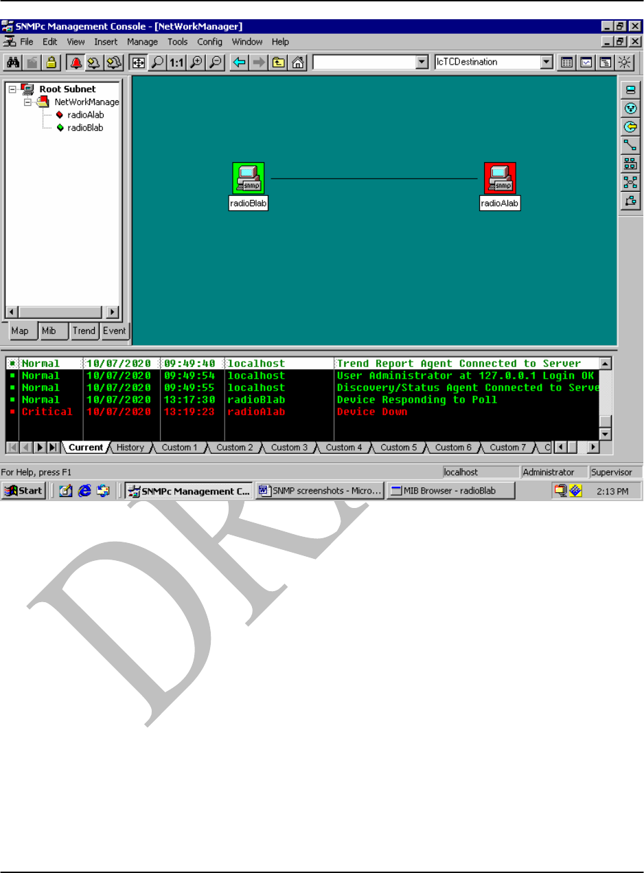
A typical example of the SNMPc7 Management Console screen display for a simple network is
shown in Figure C1. The green icon indicates that the radioBlab device is connected and
responding to polls from the NMS while the red icon indicates that the radioAlab device has a
critical failure.
The display layout shows a selection tool pane on the left with tabbed control for selection of
objects within different SNMPc functional modules. A network view window is in the centre. At
the bottom is an event log tool pane with tabbed control for display of filtered event log entries.
Refer to the SNMPc manual for additional screen layout options and use of the main button bar
and edit button bar along the top and right side of the screen display.
L1000 User’s Manual
DU1000-01 11/26/07
Loea Corporation
733 Bishop Street, Suite 1717
Honolulu, HI 96813
Phone: (808) 521-4908
Fax: (808) 521-4906
www.loeacom.com
45
Figure C1. Example of SNMPc Management Console Screen.
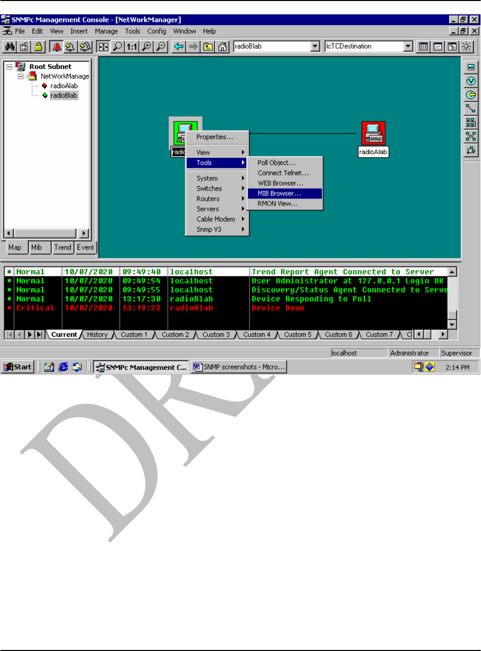
To view the MIB groups, right-click on a radio icon and select ‘Tools’ then ‘MIB Browser’. See
Figure C2.
L1000 User’s Manual
DU1000-01 11/26/07
Loea Corporation
733 Bishop Street, Suite 1717
Honolulu, HI 96813
Phone: (808) 521-4908
Fax: (808) 521-4906
www.loeacom.com
46
Figure C2 SNMPc MIB Browser Selection.
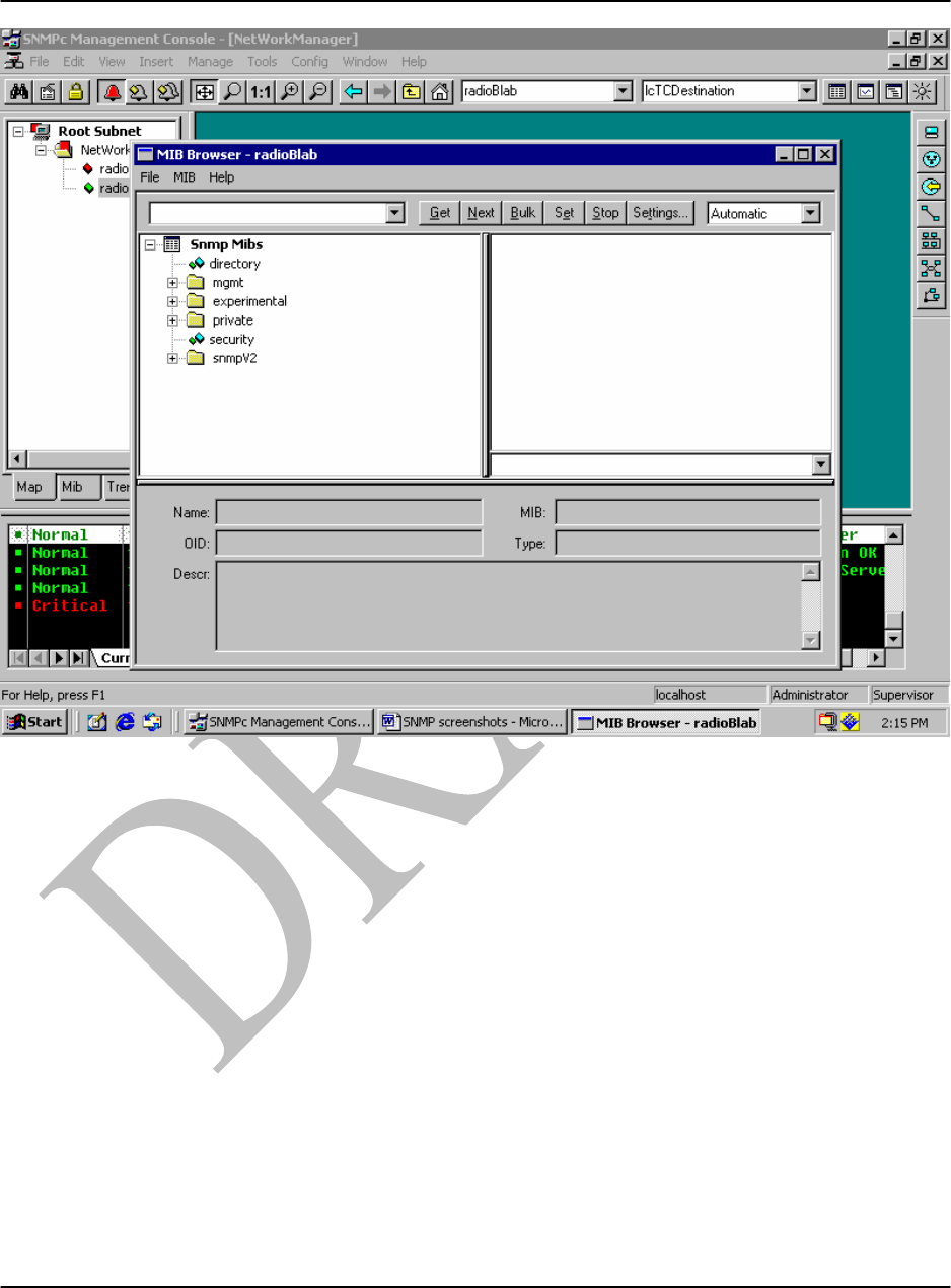
This will open a new window as shown in Figure C3.
L1000 User’s Manual
DU1000-01 11/26/07
Loea Corporation
733 Bishop Street, Suite 1717
Honolulu, HI 96813
Phone: (808) 521-4908
Fax: (808) 521-4906
www.loeacom.com
47
Figure C3 SNMPc MIB Browser.
In SNMPc it is required that the user enter the name of the person to contact about this radio, the
name of the radio which would normally be the fully qualified domain name for the radio and the
location of the radio. This is carried out by clicking on the + next to the ‘mgmt’ folder shown
near the top of the folder tree in the left side pane shown in Fig C3 above. The resulting screen
display is shown in Fig C4.
L1000 User’s Manual
DU1000-01 11/26/07
Loea Corporation
733 Bishop Street, Suite 1717
Honolulu, HI 96813
Phone: (808) 521-4908
Fax: (808) 521-4906
www.loeacom.com
48
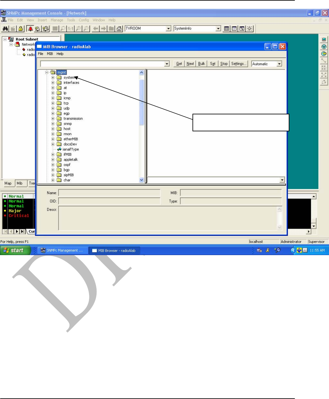
Figure C4. SNMPc ‘System’ Folder Selection.
In the left side pane click on the + next to the folder ‘system’. The screen display in Fig C5 will
appear.
Select + next to ‘system’
L1000 User’s Manual
DU1000-01 11/26/07
Loea Corporation
733 Bishop Street, Suite 1717
Honolulu, HI 96813
Phone: (808) 521-4908
Fax: (808) 521-4906
www.loeacom.com
49
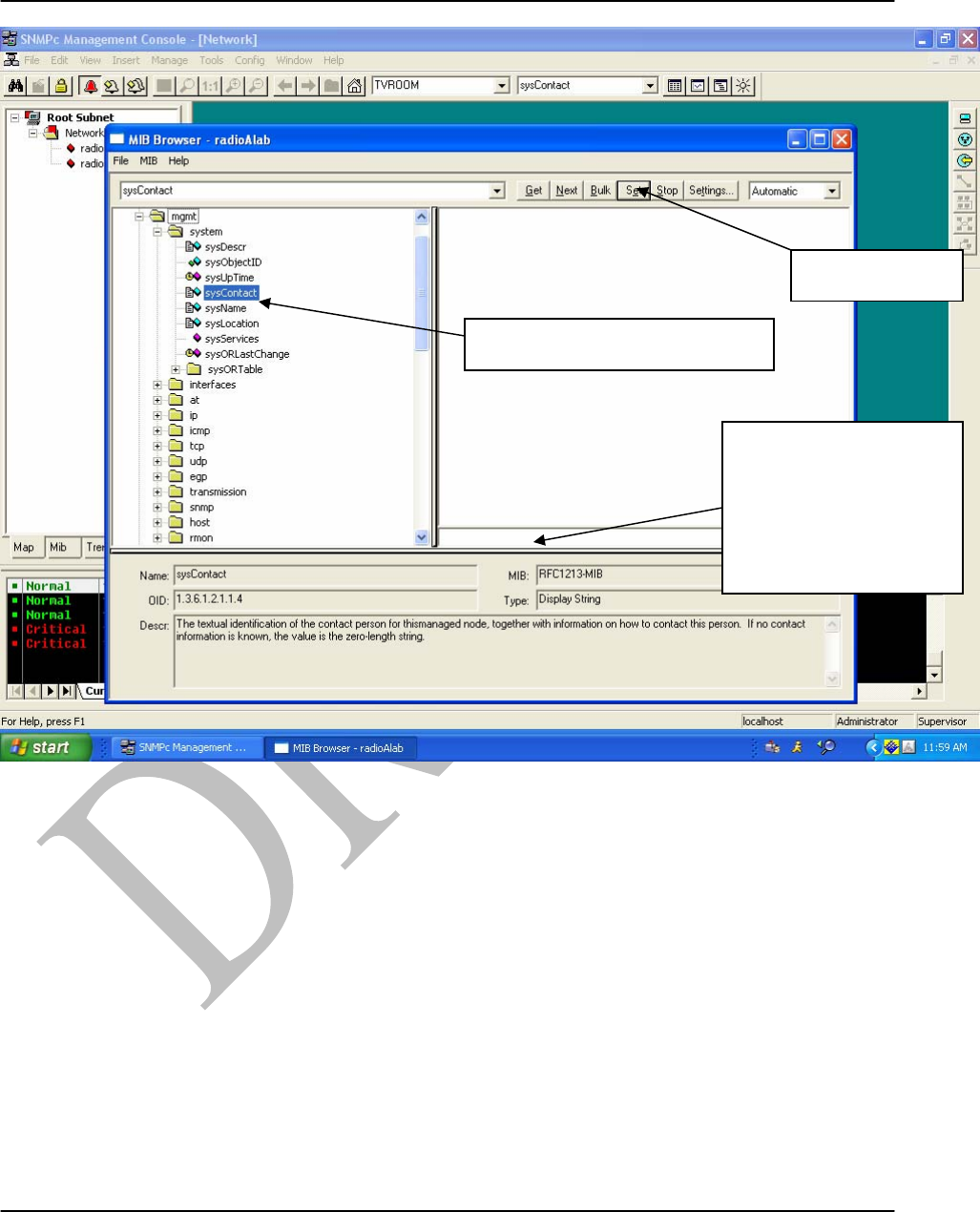
Figure C5. SNMPc ‘sysContact’, ‘sysName’ and ‘sysLocation’ Data Entry.
Double click on ‘sysContact’ as shown in Fig C5 and enter the name of the contact person in the
block indicated. Then click the Set button on the top menu row to have this information saved
into the NMS. Repeat this procedure for ‘sysName’ and ‘sysLocation’, each time entering the
appropriate information into the same block as indicated in Fig C5. When completed click on the
- sign next to ‘system’ to close the folder. The screen display should look like Fig C4 again.
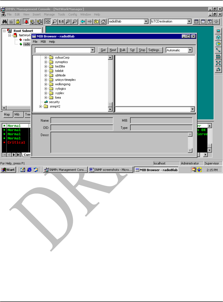
Scroll down the folder list to till the ‘private’ folder is found.
Click on the + next to the ‘private’ folder. A ‘loea’ folder should be at the bottom of that list as
shown in Figure C6.
Enter information for
sysContact or
sysName or
sysLocation in this
block
Click Set here
Double click on sysContact
L1000 User’s Manual
DU1000-01 11/26/07
Loea Corporation
733 Bishop Street, Suite 1717
Honolulu, HI 96813
Phone: (808) 521-4908
Fax: (808) 521-4906
www.loeacom.com
50
Figure C6. SNMPc Selection of Loea Folder at Bottom of ‘Private’ Folder List.
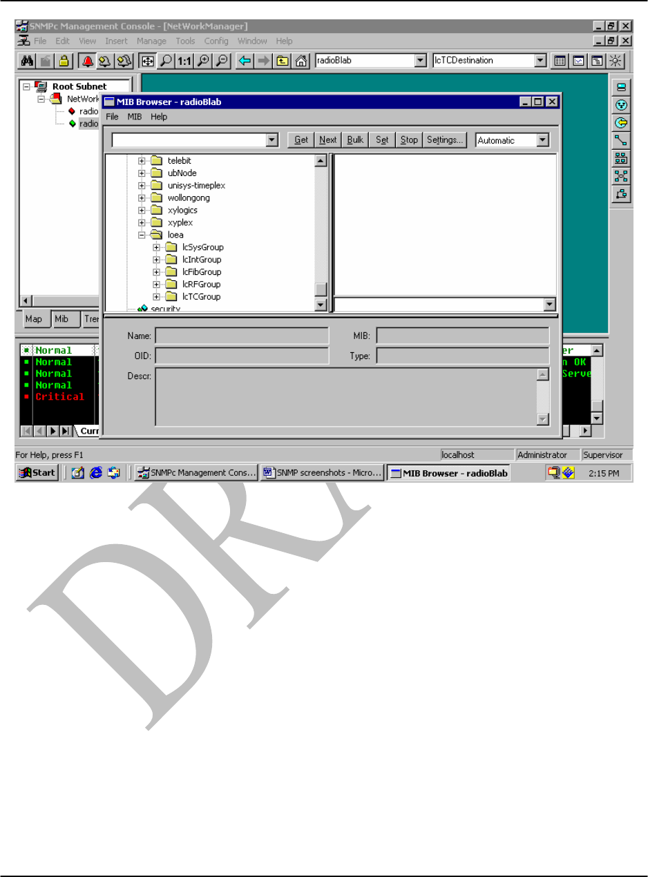
Click on the + next to the ‘loea’ folder to reveal five different Loea 1000 MIB groups as shown
in Figure C7.
L1000 User’s Manual
DU1000-01 11/26/07
Loea Corporation
733 Bishop Street, Suite 1717
Honolulu, HI 96813
Phone: (808) 521-4908
Fax: (808) 521-4906
www.loeacom.com
51
Figure C7 The ‘loea’ folder showing 5 different Loea MIB groups.
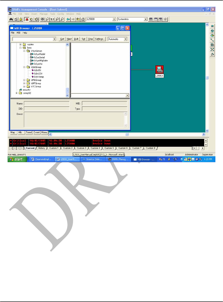
Click on the + next to one of the groups, and the individual SNMP variables should appear as
shown in Figure C8.
L1000 User’s Manual
DU1000-01 11/26/07
Loea Corporation
733 Bishop Street, Suite 1717
Honolulu, HI 96813
Phone: (808) 521-4908
Fax: (808) 521-4906
www.loeacom.com
52
Figure C8. Individual SNMP variables for group.
By double clicking on any of those variables its current value should appear in the window on
the right as shown in Figure C9.
L1000 User’s Manual
DU1000-01 11/26/07
Loea Corporation
733 Bishop Street, Suite 1717
Honolulu, HI 96813
Phone: (808) 521-4908
Fax: (808) 521-4906
www.loeacom.com
53
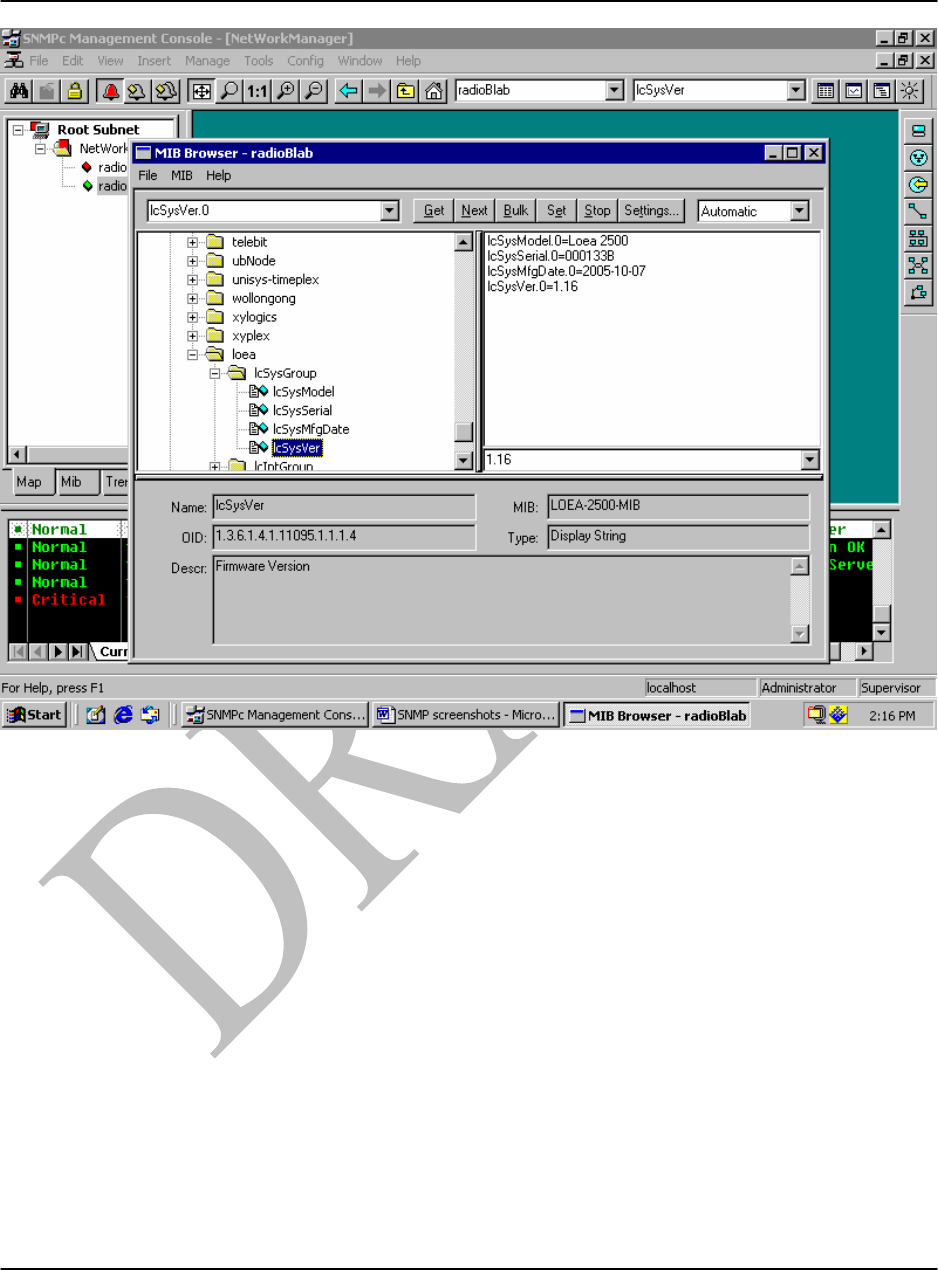
Figure C9. The System Group IcSysGroup.
Double clicking on each of the variables in each of the groups will generate a list of parameters
as shown in Figs C10 to C13.

L1000 User’s Manual
DU1000-01 11/26/07
Loea Corporation
733 Bishop Street, Suite 1717
Honolulu, HI 96813
Phone: (808) 521-4908
Fax: (808) 521-4906
www.loeacom.com
54
Figure C10. The Internal Group lcIntGroup:
This group contains information that is useful to determine the internal health of the radio,
including voltages and currents.
L1000 User’s Manual
DU1000-01 11/26/07
Loea Corporation
733 Bishop Street, Suite 1717
Honolulu, HI 96813
Phone: (808) 521-4908
Fax: (808) 521-4906
www.loeacom.com
55
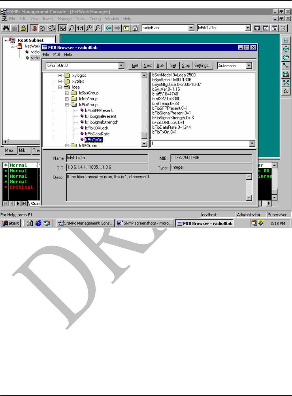
Figure C11. The Fiber Group lcFibGroup:
This group contains information that pertains to the fiber link.
L1000 User’s Manual
DU1000-01 11/26/07
Loea Corporation
733 Bishop Street, Suite 1717
Honolulu, HI 96813
Phone: (808) 521-4908
Fax: (808) 521-4906
www.loeacom.com
56
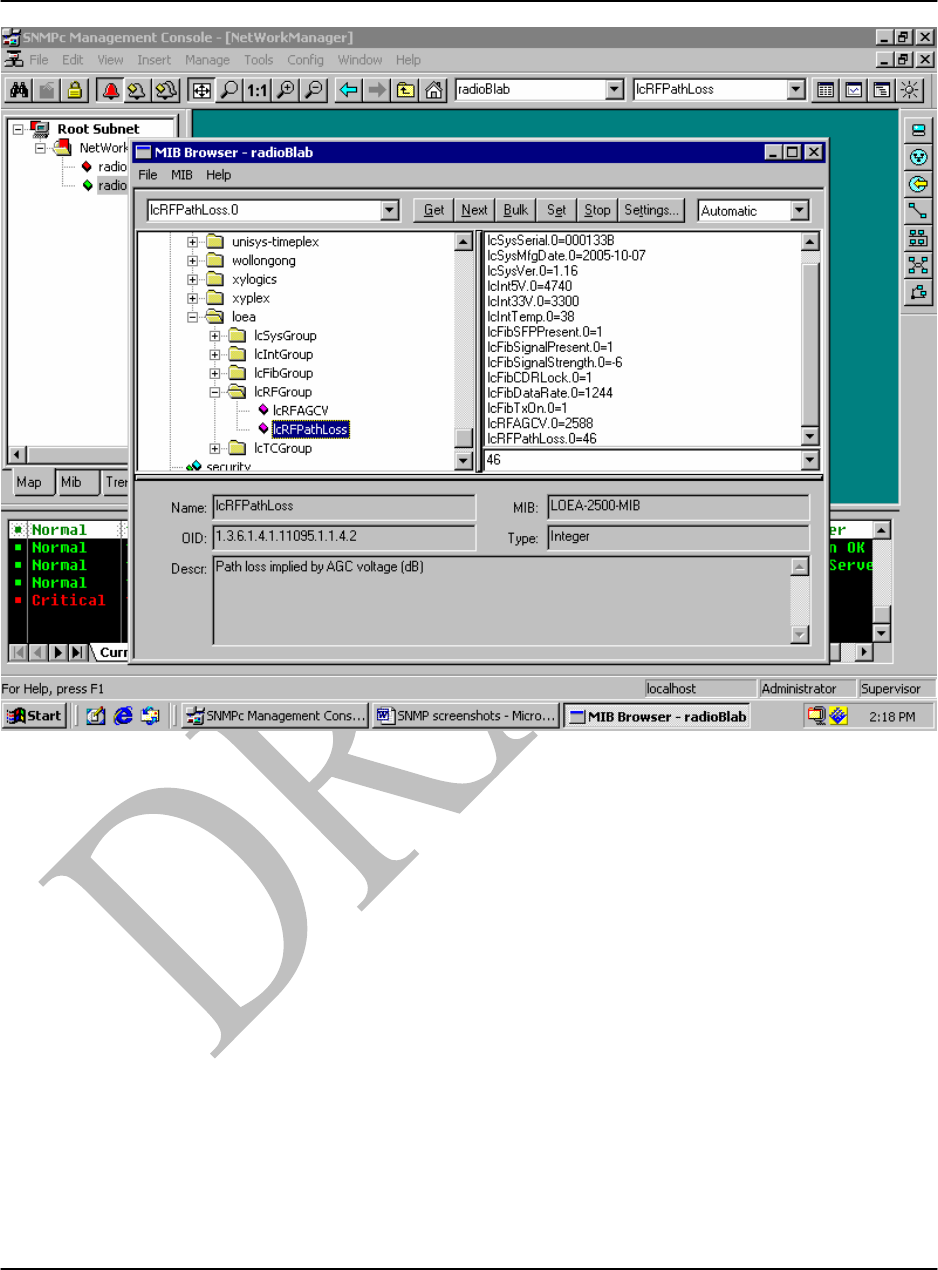
Figure C12. The RF Group lcRFGroup:
This group contains information that pertains to the RF link.
L1000 User’s Manual
DU1000-01 11/26/07
Loea Corporation
733 Bishop Street, Suite 1717
Honolulu, HI 96813
Phone: (808) 521-4908
Fax: (808) 521-4906
www.loeacom.com
57
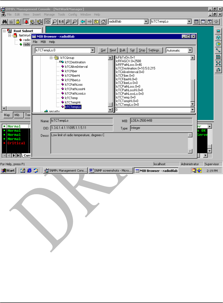
Figure C13. The Trap Control Group lcTCGroup:
This group defines the thresholds and other controls which are used to control traps. For each
analog signal, there is an enable control, a high value, and a low value. If the enable is set to 0,
this signal is ignored. If enable is set to 1, then this analog signal is compared to both the high
and low values. If it is goes from inside a range to outside, or from outside the range to inside,
the corresponding trap is generated. For each digital signal, a trap is generated each time that
signal changes state.

L1000 User’s Manual
DU1000-01 11/26/07
Loea Corporation
733 Bishop Street, Suite 1717
Honolulu, HI 96813
Phone: (808) 521-4908
Fax: (808) 521-4906
www.loeacom.com
58