Loea L2500-2 Point to Point Radio User Manual Loea Corporation
Loea Corporation Point to Point Radio Loea Corporation
UserManual.wiki
>
Loea
>
L2500 2 User Manual
Manual
Navigation menu
Upload a User Manual
Namespaces
Wiki Guide
HTML
PDF
Info
Views
User Manual
Discussion / Help
Navigation


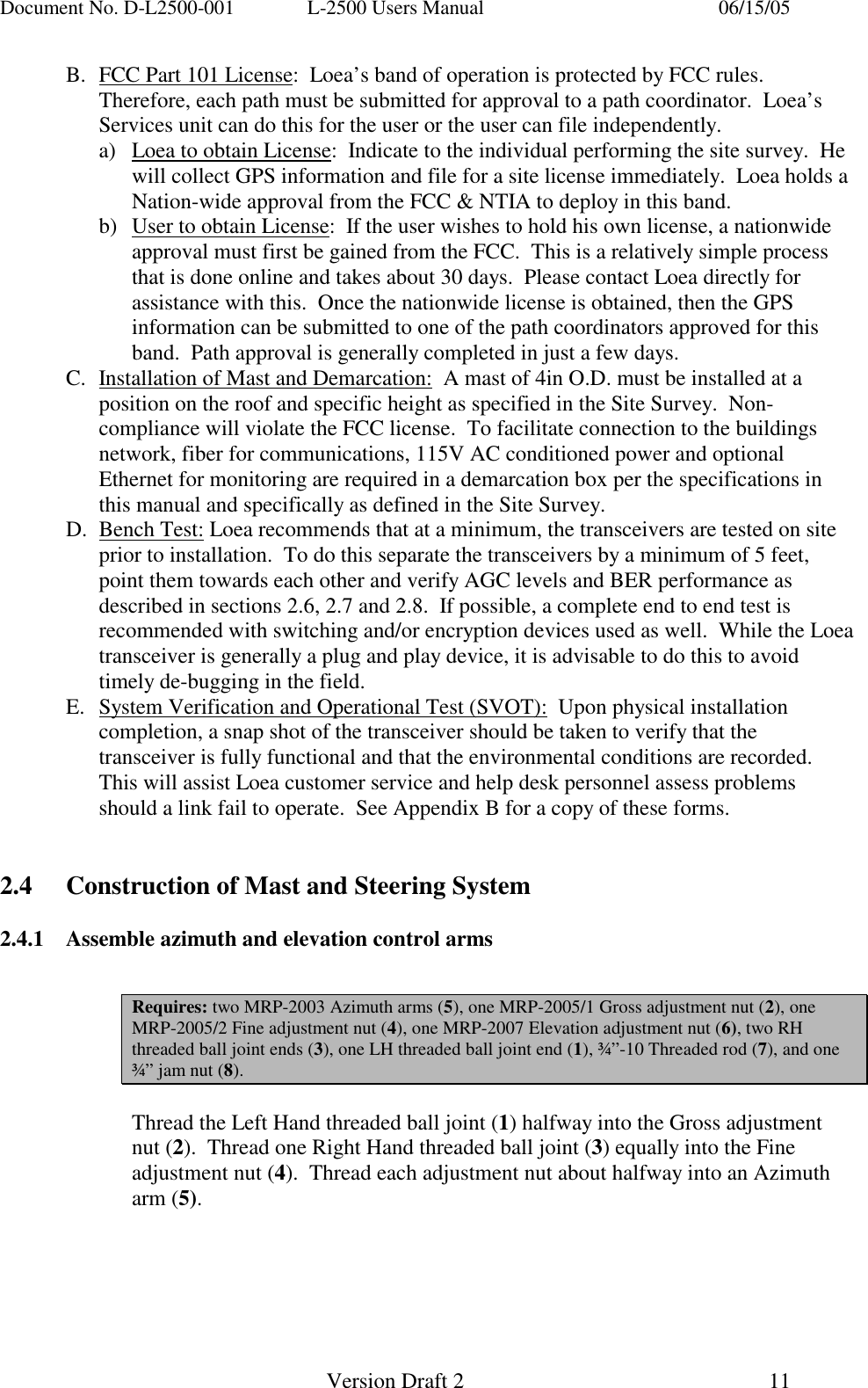
![Document No. D-L2500-001 L-2500 Users Manual 06/15/05 Version Draft 2 12 Thread the jam nut (8) and the course end (6a) of the Elevation adjustment nut (6) onto the one end of the ¾”-10 threaded rod (7) far enough to reach the hollow. Thread the ball joint (3) equally into the fine end of the adjustment nut (6b). 2.4.2 Assemble Antenna mount plate and control arms Requires: one MRP-2006 Mount plate (9), one MRP-2008 pillow block (10), four ½” Hardware Assemblies (11) consisting of [½”- 13 x 1-3/4” bolt, hex nut, lock washer, flat washer], and three ¼”-20 socket head cap screws (12). Position the Mount plate (9) so the offset tab is on the lower right while assembled. Locate the three ¼”-20 threaded holes on the tab and fasten the pillow block (10) to the plate with the socket head cap screws (12). The application of Lock-Tite™ or an equivalent compound during this step is recommended.](https://usermanual.wiki/Loea/L2500-2/User-Guide-562285-Page-12.png)
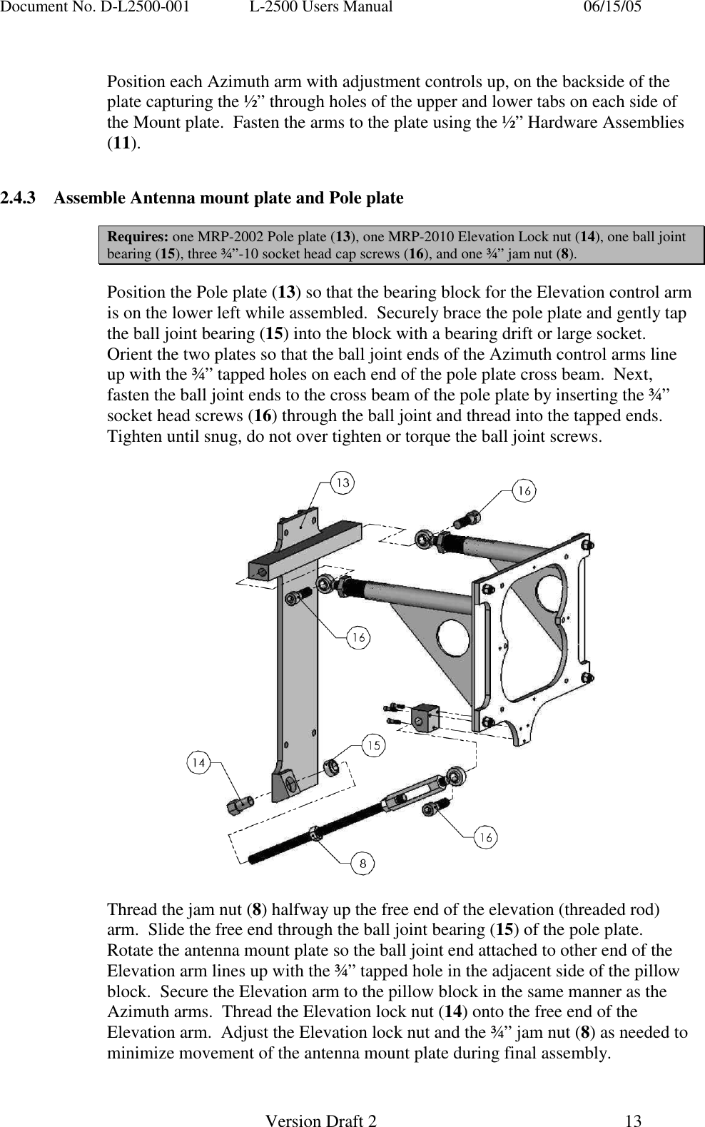
![Document No. D-L2500-001 L-2500 Users Manual 06/15/05 Version Draft 2 14 2.4.4 Attach assembly to Mast, attach antenna Requires: two U-Bolt Assemblies (17) consisting of [one 4.5” diameter, ½”-13 U-bolts, two hex nuts, two lock washers], four 3/8”-16 bolts and flat washers (18), and Antenna (19) Lifting the steering assembly from the front, press the pole plate against the mast using the parallel runners on the backside to steady the assembly while the two U-bolt assemblies (17) are installed. Once the steering system is shifted into the desired position the plate’s runners will bind to the mast as the U-bolts are tightened so as to prevent the mount from inadvertently slipping. Once the steering assembly is secured to the mast, locate the four 3/8” through holes correlating with the four threaded holes located on the backside of the antenna. Position the antenna (19) onto the mount plate in relation to the most accessible placement of the optical alignment scope. Secure the antenna to the mount using the 3/8” bolts and flat washers (18). Although the steering system can accommodate course adjustments, the mount may need to shift beyond the range of the Azimuth arms. The U-bolts can always be loosened enough to permit a slightly greater rotation to correct such alignment issues.](https://usermanual.wiki/Loea/L2500-2/User-Guide-562285-Page-14.png)