Loea L2700-2 Point to Point Radio User Manual L2700 UserManual rev081507
Loea Corporation Point to Point Radio L2700 UserManual rev081507
UserManual.wiki
>
Loea
>
L2700 2 User Manual
Manual
Navigation menu
Upload a User Manual
Namespaces
Wiki Guide
HTML
PDF
Info
Views
User Manual
Discussion / Help
Navigation
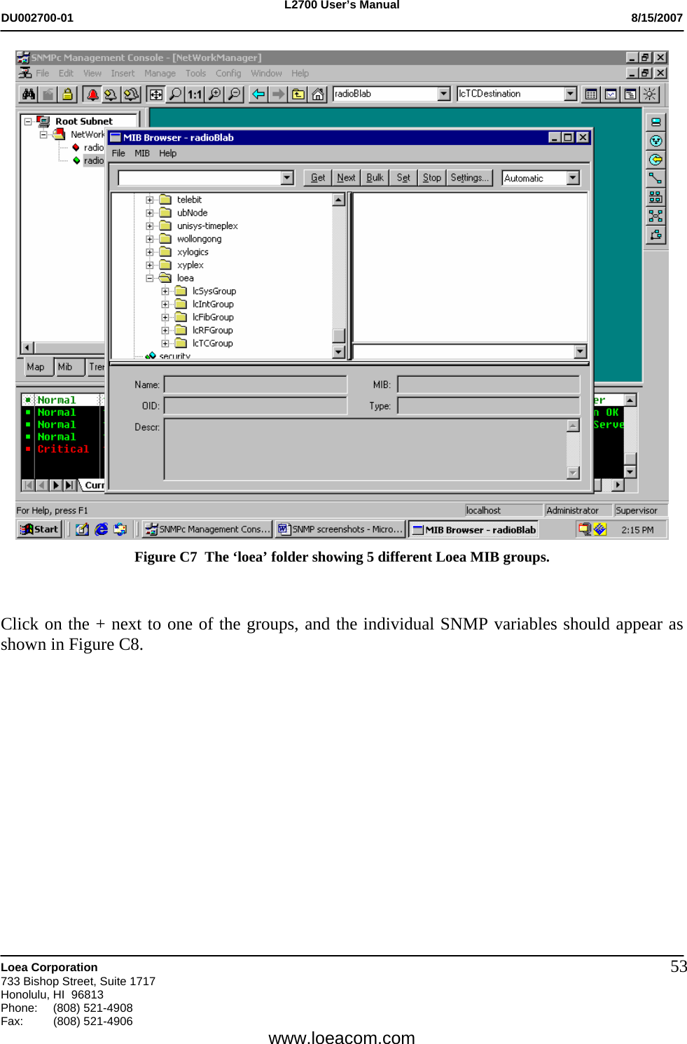
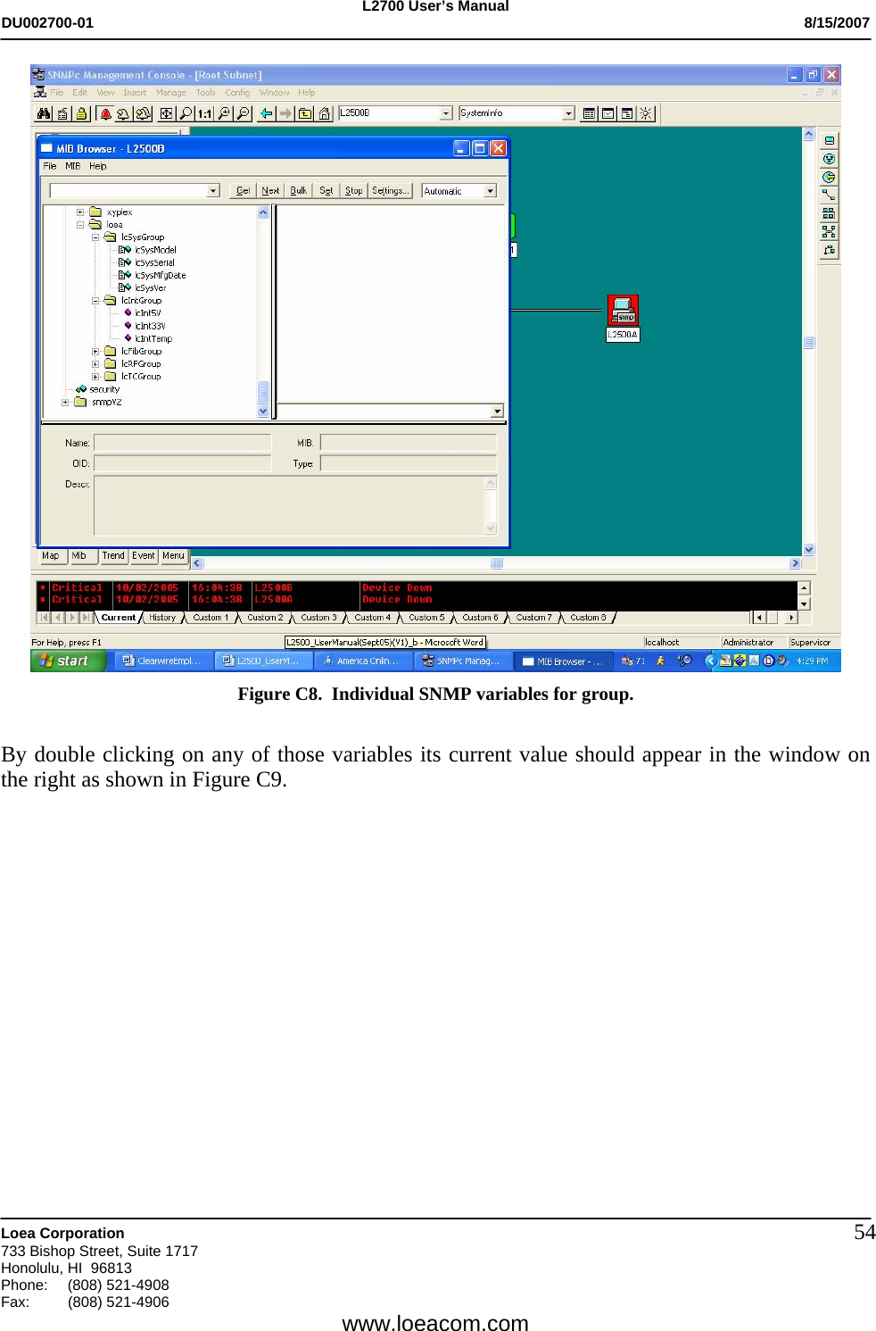
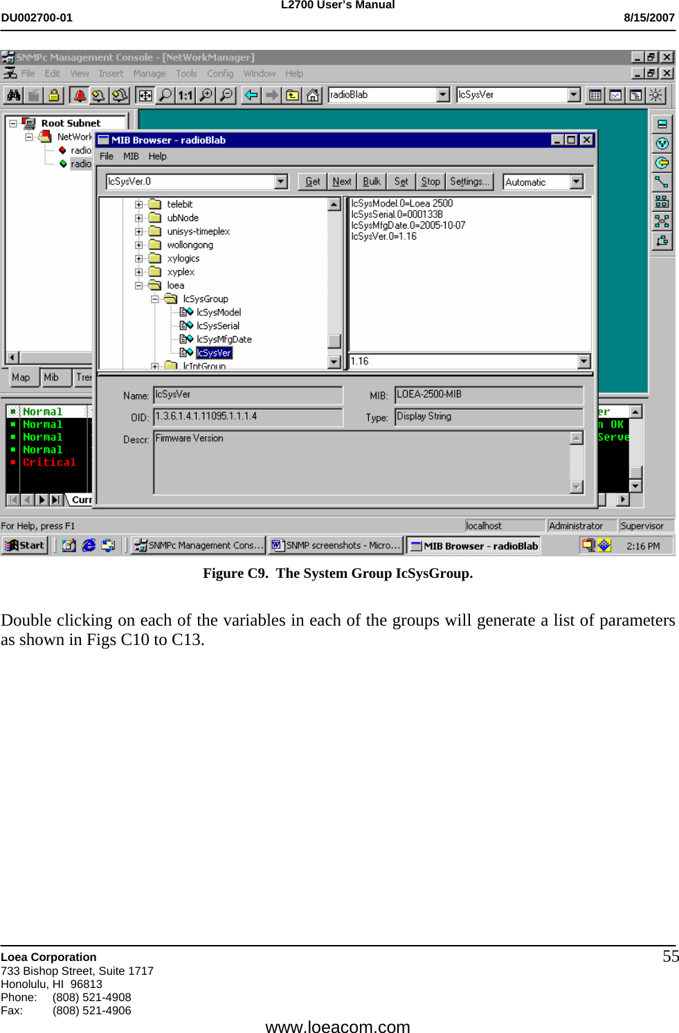
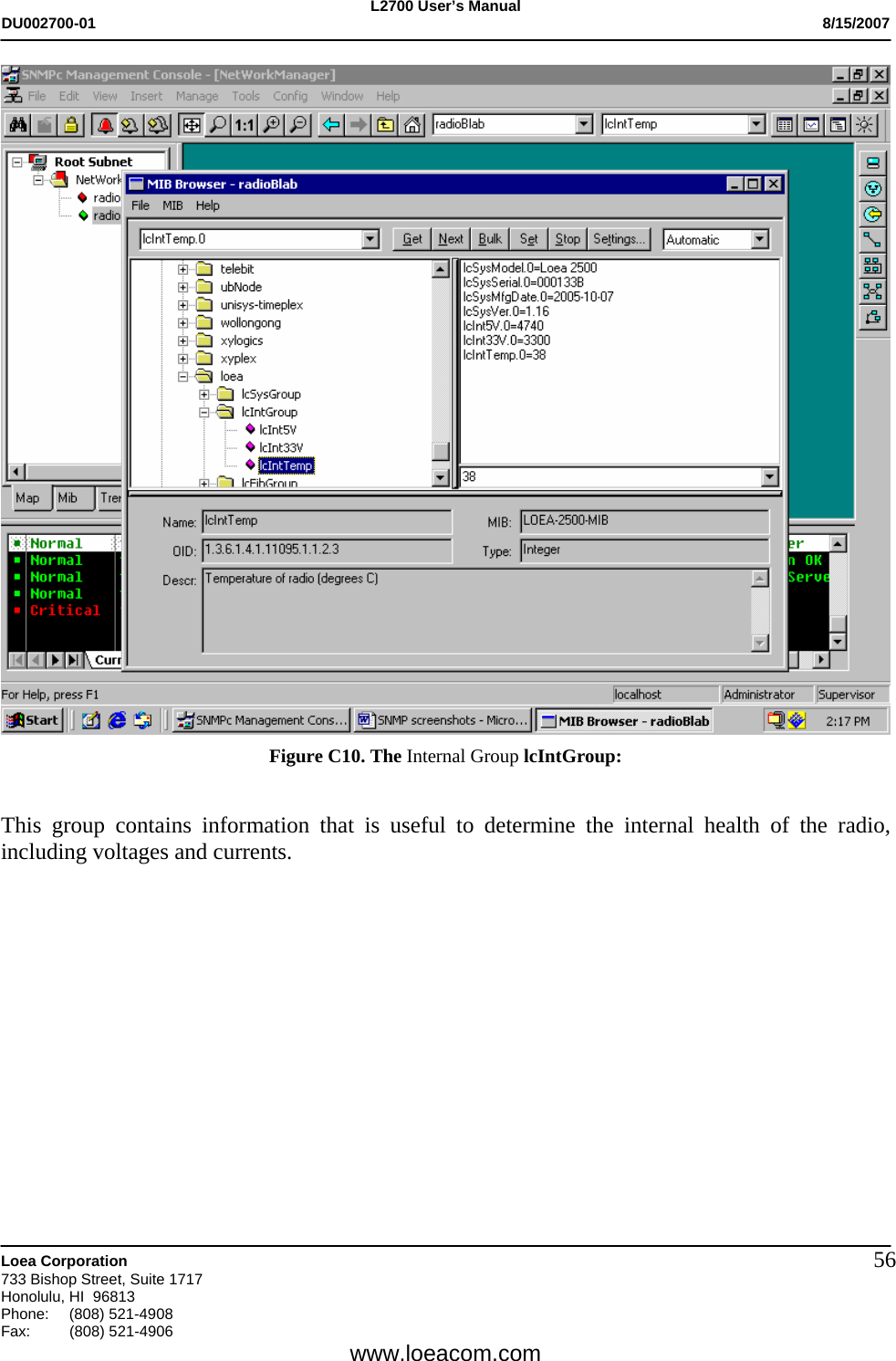
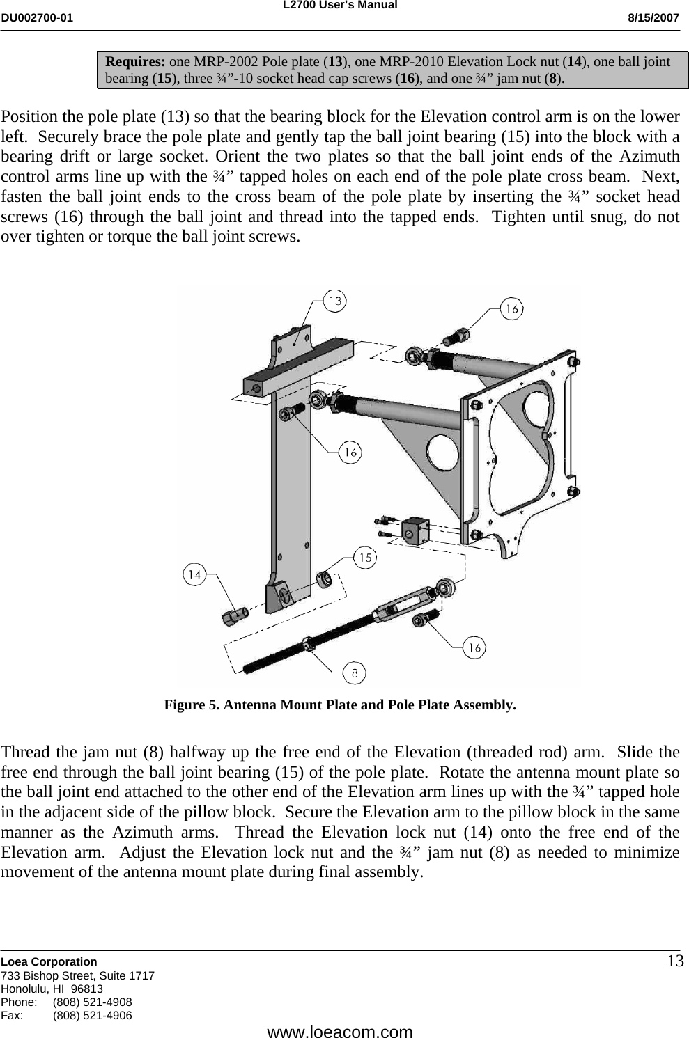
![L2700 User’s Manual DU002700-01 8/15/2007 Loea Corporation 733 Bishop Street, Suite 1717 Honolulu, HI 96813 Phone: (808) 521-4908 Fax: (808) 521-4906 www.loeacom.com 12 2.4.2 Assemble Antenna Mount Plate and Azimuth Arms (see Figure 4) Requires: one MRP-2006 Mount plate (9), one MRP-2008 pillow block (10), four ½” Hardware Assemblies (11) consisting of [½”- 13 x 1-3/4” bolt, hex nut, lock washer, flat washer], and three ¼”-20 socket head cap screws (12). Position the mount plate (9) so the offset tab is on the lower right. Locate the three ¼”-20 threaded holes on the tab and fasten the pillow block (10) to the mount plate with the socket head cap screws (12). The application of Lock-Tite™ or an equivalent compound during this step is recommended. Figure 4. Assembly of Antenna Mount Plate and Azimuth Control Arms. Position each Azimuth arm with adjustment controls up, on the backside of the mount plate capturing the ½” through holes of the upper and lower tabs on each side of the mount plate. Fasten the arms to the mount plate using the ½” hardware assemblies (11). 2.4.3 Assemble Antenna Mount Plate and Pole Plate (see Figure 5)](https://usermanual.wiki/Loea/L2700-2/User-Guide-873582-Page-12.png)
![L2700 User’s Manual DU002700-01 8/15/2007 Loea Corporation 733 Bishop Street, Suite 1717 Honolulu, HI 96813 Phone: (808) 521-4908 Fax: (808) 521-4906 www.loeacom.com 142.5 Attach Assembly to Mast and Attach Antenna (see Figure 6) Requires: two U-Bolt Assemblies (17) consisting of [ one standard 4’’mast (4.5” diameter actual), ½”-13 U-bolts, two hex nuts, two lock washers], four 3/8”-16 bolts and flat washers (18), and Antenna (19). Lifting the steering assembly from the front, press the pole plate against the mast using the parallel runners on the backside to steady the assembly while the two U-bolts (17) are installed. Once the steering system is shifted into the desired position the plate’s runners will bind to the mast as the U-bolts are tightened so as to prevent the mount from inadvertently slipping. Figure 6. Attaching Assembly to Mast and Attach Antenna. Once the steering assembly is secured to the mast, locate the four 3/8” through holes correlating with the four threaded holes located on the backside of the antenna. Position the antenna (19) onto the mount plate. Secure the antenna to the mount using the 3/8” bolts and flat washers (18). Although the steering system can accommodate course adjustments, steering assembly may need to shift beyond the range of the Azimuth arms. The U-bolts can always be loosened enough to permit a slightly greater rotation to correct such alignment issues.](https://usermanual.wiki/Loea/L2700-2/User-Guide-873582-Page-14.png)