LogiTag Systems LTT-03 Resident Tag User Manual
LogiTag Systems Ltd. Resident Tag
Users Manual

LT‐D‐0211rev16
Page|1
LogiTrack
UserGuide

LT‐D‐0211rev16
Page|2
Contents
1.SaftyPrecautions..................................................................................................................................6
2.IntroducingtheSystem.........................................................................................................................9
3.LogiTrackComponents........................................................................................................................10
3.1.BaseStation............................................................................................................................10
3.2.GateLocator............................................................................................................................14
3.3.GateExciterGPRS...................................................................................................................18
3.4.4ChannelExciter....................................................................................................................22
3.5.1ChannelExciter....................................................................................................................27
3.6.RemoteDoorindicator...........................................................................................................30
3.7.LFantennas.............................................................................................................................34
3.6.1Ceilingantenna...................................................................................................................34
3.6.2Doorantenna......................................................................................................................36
3.6.3Antennainstallationexamples............................................................................................38
3.7Tags.............................................................................................................................................39
3.7.1General................................................................................................................................39
3.7.2Attachingtagstoobjects....................................................................................................42
3.7.3Stafftagfunctionality..........................................................................................................42
3.8SystemRanges............................................................................................................................43
4.GeneralWarningandinstructions......................................................................................................44
4.1Relay(Drycontact)connection...................................................................................................44
5.Infrastructureanddataflowsketch...................................................................................................47
5.1Siteinstallationexample.............................................................................................................48
6.SoftwareInstallation...........................................................................................................................49

LT‐D‐0211rev16
Page|3
6.1InstallingtheTechnician‐Station.................................................................................................49
6.2SoftwareOperation.....................................................................................................................49
6.3ApplicationStructure..................................................................................................................50
6.4Connectingtoaunit....................................................................................................................51
6.4.1AddingaBase‐Station.........................................................................................................51
6.4.2AddingaGatelocator.........................................................................................................52
6.4.3DefiningaunitIDtotheGateLocator................................................................................52
6.4.4ViewingConnectivityStatus................................................................................................53
6.4.5“Base‐StationSetup”Tab....................................................................................................55
6.4.6RFzones(Lfantennas)configuration..................................................................................56
6.4.7AdvancedOperationalParameters.....................................................................................57
6.4.8“TagsSetup”Tab.................................................................................................................58
6.4.9Sensors&tagdefinitions....................................................................................................59
6.4.10“Enrollment”Tab................................................................................................................61
6.4.11“Detection”Tab..................................................................................................................63
6.4.12“Base‐StationOperation”Tab.............................................................................................65
6.4.13“Reports”Tab......................................................................................................................66
6.4.14“Log”Tab.............................................................................................................................67
7.Troubleshooting..................................................................................................................................68
7.1Connectivityissues......................................................................................................................68
7.1.1Softwareconnection...........................................................................................................68
7.1.2Driverinstallation................................................................................................................69
7.2Hardwareissues..........................................................................................................................70
7.2.1LFsignaldoesnottransmits................................................................................................70

LT‐D‐0211rev16
Page|4
7.2.2Unitdoesn’tturnon............................................................................................................70
7.2.3Theunitisonbutnoresponse............................................................................................70
7.2.4Tagdoesnotrespond..........................................................................................................71
8.RadioApprovals..................................................................................................................................72
8.1BaseStation\GateLocator\GateExciterGPRS\4ChannelExciter..............................................72
8.1.1USA(FCC)............................................................................................................................72
8.2OneChannelExciter....................................................................................................................73
8.2.1USA(FCC)............................................................................................................................73
8.3RemoteDoorIndicator...............................................................................................................74
8.3.1USA(FCC)............................................................................................................................74
8.4StaffTag......................................................................................................................................75
8.4.1USA(FCC)............................................................................................................................75
8.5ResidentTag................................................................................................................................76
8.5.1USA(FCC)............................................................................................................................76
9.Powersupplyreuiermants..................................................................................................................77
9.1Limitedpowersource:................................................................................................................77
9.2Mainsupplynetwork:.................................................................................................................77
Abbreviations:
LT‐D‐0211rev16
Page|5
Base station CMU (Central Management
Unit)
Gate locator DMU (Door Management Unit)
4 channel Exciter MLU (Multi Location Unit)
Gate Exciter GPRS Door Management Unit GPRS
1 channel Exciter SLU (Single Location Unit)
Remote Door indicator LIU (Lights Indication Unit)
Ceiling antenna CAU (Ceiling Antenna Unit)
Door antenna DAU (Door Antenna Unit)
Staff tag SIU (Staff Indication Unit)
Patient tag PIU (Patient Indication Unit)

LT‐D‐0211rev16
Page|6
1. SaftyPrecautions
Precautions
WARNING
WARNING
Inanycaseofsmoke,strangeodororunusualnoise–pleaseshutdownall
equipmentoperationandperformapowershutdown
Besuretousethespecifiedpowersource
Incaseofwateroranyliquidspilledintotheequipment,donotcontinuetouse
theequipment.Performanimmediatepowershutdown
CAUTION
Avoidwateratalltimeswhenworkingwiththesystem.Nevertouchortry
repairinganyelectricalequipmentorcircuitswithwethands.
Makesurethatthedirectionandpolarity(+/−)arecorrectwhenConnecting
terminalblocksandconnectors.
Donotallowpiecesofmetal,wireclippings,orfinemetallicshavingsorfilings
frominstallationtoentertheproduct.Doingsomayoccasionallyresultin
minorelectricshock,fire,ormalfunctions.
Donotattempttodisassemble,repair,ormodifytheproduct,ortouchthe
internalpartsoftheproduct.Doingsomayoccasionallyresultinminorelectric
shock,fire,ormalfunctions.

LT‐D‐0211rev16
Page|7
PrecautionsforSafeUse
Besuretoobservethefollowingprecautionstoensuresafeuseoftheproduct.
1. Transporttheproductintheboxinwhichtheproductwaspacked.Makingsuretheproductisnot
subjectedtoexcessivevibrationsorshock,ordropped.
2. Storetheproductwithinthespecifiedenvironment.
3. Usetheproductwithinthespecifiedtemperatureandhumidityranges.
4. Donotusetheproductinthefollowinglocations:
4.1. LocationssubjecttoextremetemperaturechangesresultingincondensationLocationssubject
tostaticelectricity,excessivenoise,orelectricfieldsLocationswheretheproductmaycome
intocontactwithwater,oil,orchemicals.
4.2. Locationswherecorrosivegasesorflammablegasesarepresent
4.3. Locationssubjecttospatters,ironchips,orfilings
5. Donotinstalltheproductoutdoors
6. DonotreversethepowersupplyconnectionorconnecttheproducttoanACpowersupply.
7. Usethecorrectpowersupplyvoltage.
8. Donotapplyvoltagetotheinputsexceedingtheratedvoltagerange.
9. Alwayssettheproductafteritisinstalledorreplaced.Settheproductcorrectlyaccordingtothe
manual,andbesuretoperformthetestsprovidedwiththeproductbeforeoperatingit.
10. Whenoperatingtheproduct,checkwhetheranexistingsystemispresent,anddesignthesystem
carefullytopreventradiointerference.
11. Donotapplyexcessvibrationsorshocktothisproduct.Donotdropthisproduct.
12. Makesurethattheantennasarenotdisconnectedduringoperation.
13. Donotusethisproductnearotherdevicesthatmaycauseamalfunctiontothesystemsuchas
electricalcabinet.
14. TurnOFFthepowersupplybeforeperforminganywiringorreplacingdevices.
15. Donottouchtheproductwithwethands.
Powersupplyrequirements:
Thereare2optionsofpowersupply:
1. LocalLPS24Vpowersupply.Useonlycertifiedpowersupplywithrelevantapprovals.
TheapprovedbyLogiTagare:
EDACp/nEA10721B-2404
MEANWELLp/nGS60A24
Customermyuseequivalentpowersupplyonly.
2. Mainpowersupplyof24Vforfewsystems.Aunitofupto40Asupplycanbeused,certifiedfor
thecountry/zonewherethesystemsused.Seeatchapter9powersupplyrequirementsfor
powerlinesinstallationrequirements.

LT‐D‐0211rev16
Page|8
PrecautionsforCorrectUse
Alwayscheckoperationsbeforeusingtheproduct.
Preventfaultyoperation,malfunction,oradverseeffectontheproduct'sperformanceandfunctionality.
1. Communicationsperformancewillvaryaccordingtotheoperatingenvironment.
2. Donotinstalltheantennainalocationsurroundedbymetal.
3. Installtheantennacableasfarawayaspossiblefromanyelectricwiresormetalplates.
4. Donotusethisproductinareasexposedtoextremelyhighhumidity.
5. Makesurethattheallconnectionsarescrewedproperlyandnoexposedwires
6. Donotpullorbendcableswithforce.
Professionalinstallationrequirements
LogiTag'sActivesystemproductscanonlybeinstalledbycertified,professionalpersonnel.
CertificatewillbegrantedbyLogiTagorAuthorized3rdparty.
Eachinstallerreceivesspecialtraining,whichisaconditionforreceivingthelicensefromLogiTagto
becomea"licensed"installer.Theinstallationitselfisauniqueprocedure.

LT‐D‐0211rev16
Page|9
2. IntroducingtheSystem
WhatistheLogiTrack?
TheLogiTracksystemisanActive‐RFIDbasedinfrastructure,constructedfromthefollowingelements:
BaseStations–amanagementunitthatcontrolsthegatelocators
GateLocators–subunitofthebasestation.LFexcitingandUHFretrieval.Havetheability
torunlogicalandbusinessrules
4channelexciter‐subunitofthebasestation.Upto4channelLFexcitingantennas
1channelexciter‐subunitofthebasestation.1channelofLFexcitingantennas
LFAntennas‐detectionantennathatgeneratesRFIDzones
UHFantennas–UHFdataretrievalandtransmit
RemoteDoorindicator–WirelessLEDsdevice.OperatesbyUHFcommandsfromthebase
station
Tags–RFIDtagsthatcontainsauniqueIDandhavemanyfunctionalities
ThesystemenablesrealtimetrackingonobjectsbyplacingRFIDtagsontheobjectsanddetectingthem
bytheuseofallsystemcomponents.
Techniciansoftware‐
TheTechnician‐StationissoftwareprovidedbyLogiTag,enablingsystemadministratorstoconnect,
activateandconfigurethevariousequipment,andsetitupinasystemperspective.
ThedetailedfunctionalityprovidedbytheTechnicianStationis:
Define,connectandconfigureBase‐Station
Define,connectandconfigureGatelocator
Activateandconfiguretags,includingtheconfigurationofspecificsensors
Receiveanddisplaymessagesreceivedfromtags
Enableenrollmentoftagstodefinedassets
Providedetailedinformationthroughreports
ProvidealogfileofallrawdatareceivedfromtheBase‐Stations
Enableinterfacesto3rdpartsystems

LT‐D‐0211rev16
Page|10
3. LogiTrackComponents
ThefollowingdescribesthecomponentsofaLogiTracksystem:
3.1. BaseStation
TheBase‐Stationfunctionalizesasthemanagementunit.Thebasestationpurposeistomanagethe
subunits–gatelocators.Itcarriesoutthefollowingfunctionalities:
Managementunit–thedatathatisreceivedonthegatelocatorsistransferredtothebase
stationwithanindicationonwhichunitsendsthedata.
Theunitisabletosendconfigurationinfothegatelocatorsvia869.85/916MHz(area
dependent)
Transferringdata–theBase‐StationreceivesovertheUHFband.themessagestransmitted
bythetagstothegatelocatorandthentothebasestation.Itcansendthemaresponse(to
acknowledgethereception);senddatatoamainserver,triggerlocalhardwarethroughdry‐
contactinterfacesorstartacontinuouscommunicationsessionwiththetag.
Independentunit–theunitcanfunctionandconnecttoaserver.
Basestationcanconnectthecustomercomputer/managementsystemviaEthernet,GPRSorWIFI.
Notethatthebasestationinstallationmustbeseparatedfromelectricityandcommunication
infrastructure
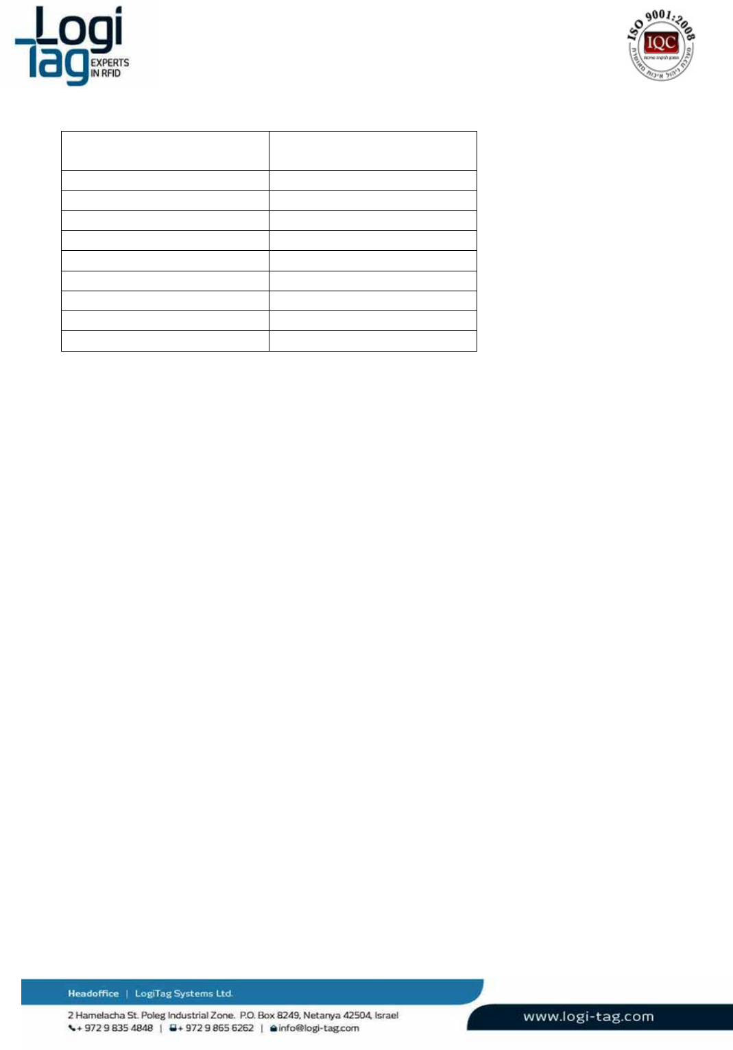
Technicaldetails:
Power
Powersupply24VDC
Maximumcurrentconsumption2A
Backupbattery9Ahrechargeable
FusePTC2.5A
Airinterface
UHFinterface3X433MHz,1X869.85/916 MHz
UHFrangeUpto25m
LFinterfaceNone
LFrangeN/A
Hostinterface
USB2XUSB(115.2Kbps)
Ethernet10/100Mbps
Wi‐Fi802.11b/g,up‐to54Mbps(optional)
GPRSGPRSconnection(optional)
I/Ointerfaces
Relays4Xnormallyopenrelaycontacts.250VAC/5Aeach
Inputs4Xlowlevelsignalanalog/digitalinputs

LT‐D‐0211rev16
Page|11
Outputs4Xgeneraluseoutputs,V=24VImax=20mAforeach
LEDs12XLEDs
Memory
EEPROM128MB
Flash128MB
Environmental
Operationaltemperature‐10°C÷+45°C
Storagetemperature‐20°C÷+70°C
Dimensionsandweight
DimensionsLXWXH‐275X159X57mm
Weight1.23Kg
Backupbatteryreplacements
Warnings:
1. InanycasebeforereplacingadviceyourlocalsuppliertechnicalsupportorLogitagcustomers
support.
2. Onlyauthorizedtechniciancanreplacebattery.
3. Disconnecttheunitfromthepowersource.
4. UsebatterywhichapprovedbyLogitagforassemblyattheunit.
5. Batterymustberechargeabletype3.7‐4.2V.
Replacementprocedure:
Disconnecttheunitfrompowersourceandallothercablesconnectiontotheconnectorspanel.
Openthe4screwsofthedevice.
Removethebattery
Connectthenewbattery
Installationinstructions
Installationpositions:
Vertically–placedonashelforatable,antennasadjustedandpointedtotheceiling.
Wallmount‐Screwedtothewallbyusingthesidebrackets,antennasadjustedandpointedto
theceiling.
PowerConnection:
Connectthepowerconnectiontothepowersocketandtotheunitat"power"connection.
Relayandantennas:
Relayconnection–seeRelay(Drycontact)connectionsection.
Antennas–connecttheantennastoanyportavailableonLFantennasports1‐4.
Serviceinstructions
Theunitmustbekeptawayfrommetal,heat(above60°Celsius\140Fahrenheit)andwater.
Cleaninginstructions
Nocleaningisrequired
LT‐D‐0211rev16
Page|12
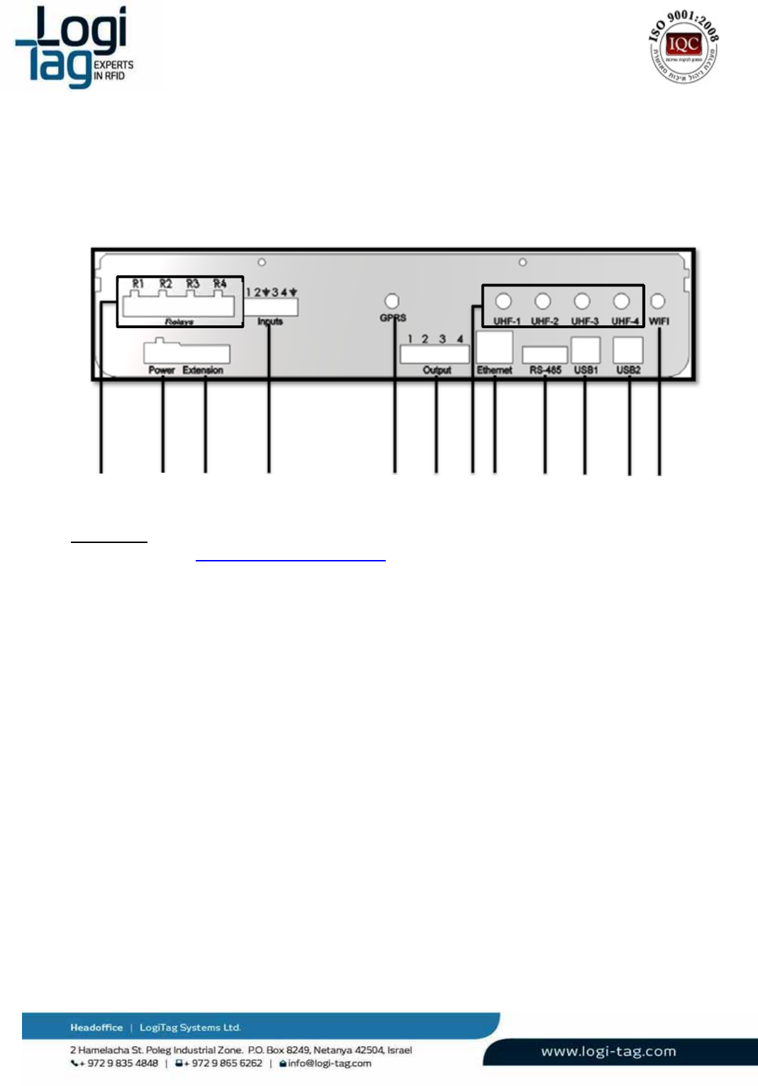
Wiringinstructions
Connections:
1. Relays‐seeRelay(Drycontact)connectionsection.
2. Power–connecttheunittothepowersocketbyusing24vadaptor
3. Extension–useforboardhardwareextensions
4. Inputs–connectdigitalcontrolinputs.
5. GPRS‐connectaGPRSantenna
6. Output–optiontooperateloadsat24Vwithsoftwarerulesoptions.
7. UHFantennas–connecta433MHzantennastoUHF1‐3,UHF4canbeeither:
‐ 916MHz(USA,IL)
‐ 869.85Mhz(Europe)
8. Ethernet–connectaCAT5EEthernetcable
9. RS‐485‐communicationport
10. USB1‐connectaUSBcabletocommunicatewiththeLowlevelcontroller
11. USB1‐connectaUSBcabletocommunicatewiththeHighlevelcontroller
12. WI‐FI‐connectorforWIFIantenna
1
2
3
4
5678910
11
12
LT‐D‐0211rev16
Page|13
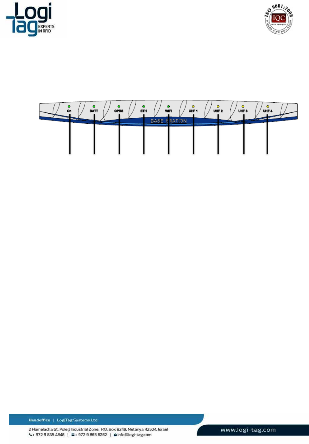
Frontpanelindications
LEDindication:
1.
On–LEDindicationforpowerconnection
2.
Batt‐LEDindicationforabatteryconnectedandworking
3.
GPRS‐LEDindicationforGPRSconnectionestablished
4.
ETH‐LEDindicationforETHconnectionestablished
5.
Wi‐Fi‐LEDindicationforWI‐FIconnectionestablished
6.
UHF1‐DNA
7.
UHF2‐DNA
8.
UHF3‐indicationforreceivingsensortag
9.
UHF4‐indicationforcommunicatingwithexciter
Warnings
Battery‐Riskofexplosionifbatteryisexposedtoextremeheat
Exposedwires–Riskofshockwhentouchingexposedwires
WaterExposure‐Riskofshockwhentouchingtheunitexposedtowater
1
2
3
456789
LT‐D‐0211rev16
Page|14
3.2. GateLocator
TheGateLocatorhas3mainfunctions:
GenerateRF‐Zonesusinganinternal125KHztransmitter.EachoftheGateLocator's
channelscarriesauniquenumberasanidentifiertothelocation/areawheretheRF‐Zoneis
operates.
Operateslogicalrules:basedonevents(tagdetection,sensordetection,locationdecision,
etc.)thattheunitsdetectsitactivatesactions(I/O,parameterupdate,etc.)
Functionasarepeatertotag’stransmissions,relayingittowardtheBase‐Stationunit.
Independentunit–theunitcanfunctionandconnecttoaserver.
GateLocatorcanconnectthecustomercomputer/managementsystemviaEthernetorWIFI.
NotethattheGatelocatorinstallationmustbeseparatedfromelectricityandcommunication
infrastructure
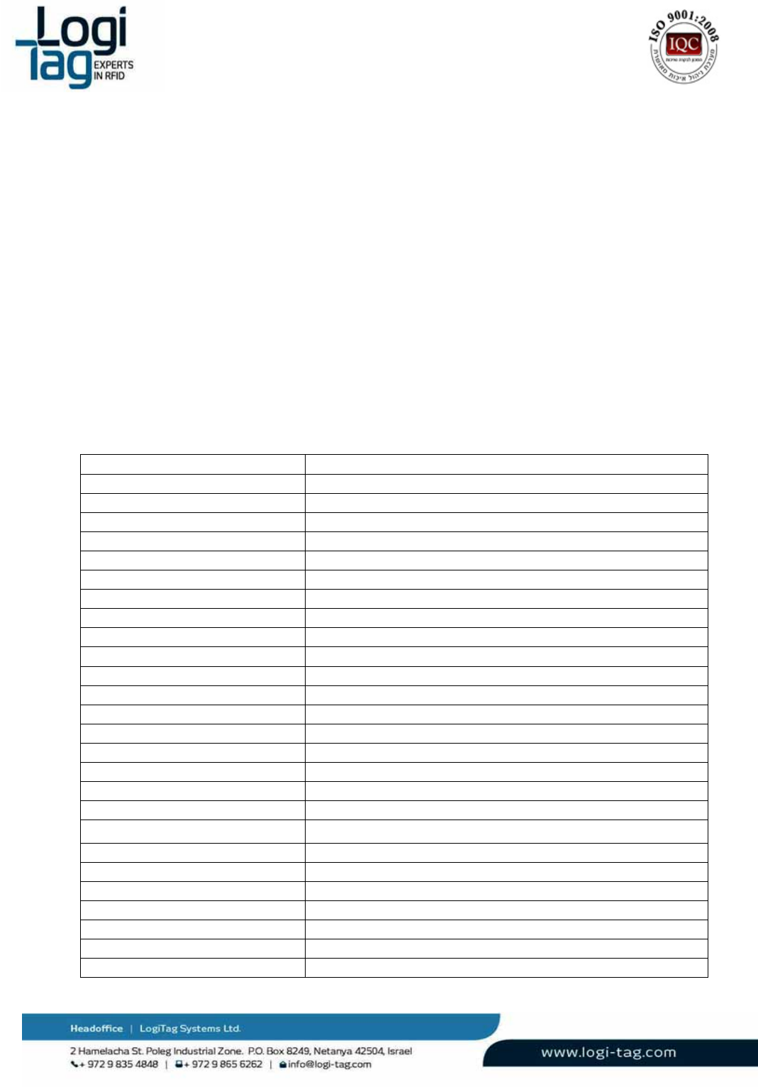
Technicaldetails:
Power
Powersupply24VDC
Maximumcurrentconsumption2.5A
Backupbattery9Ahrechargeable
FusePTC2.5A
Airinterface
UHFinterface3X433MHz,1X869.85/916MHz
UHFrangeUpto25m
LFinterface4X125KHz
LFrange0–10m
Hostinterface
RS2322XRS232(115.2Kbps)
Ethernet10/100Mbps
Wi‐Fi802.11b/g,up‐to54Mbps(optional)
GPRSnone
I/Ointerfaces
Relays8Xnormallyopenrelaycontacts.250VAC/5Aeach
Inputs8Xlowlevelsignalanalog/digitalinputs
Outputs8Xgeneraluseoutputs,V=24VImax=20mAforeach
LEDs12XLEDs
Memory
EEPROM128MB
Flash128MB
Environmental
Operationaltemperature‐10°C÷+45°C
Storagetemperature‐20°C÷+70°C
Dimensionsandweight

LT‐D‐0211rev16
Page|15
DimensionsLXWXH‐275X159X57mm
Weight1.29Kg
LFAntennaspowersettings:
ForeachLFantennayoucanconfigureviasoftware,theoutputpoweratrangeofbetween10to100%.
Backupbatteryreplacements:
Warnings:
1. InanycasebeforereplacingadviceyourlocalsuppliertechnicalsupportorLogitagcustomers
support.
2. Onlyauthorizedtechniciancanreplacebattery.
3. Disconnecttheunitfromthepowersource.
4. UsebatterywhichapprovedbyLogitagforassemblyattheunit.
5. Batterymustberechargeabletype3.7‐4.2V.
Replacementprocedure:
Disconnecttheunitfrompowersourceandallothercablesconnectiontotheconnectorspanel.
Openthe4screwsofthedevice.
Removethebattery
Connectthenewbattery
Installationinstructions
Installationpositions:
Vertically–placedonashelforatable,antennasadjustedandpointedtotheceiling.
Wallmount‐Screwedtothewallbyusingthesidebrackets,antennasadjustedandpointedto
theceiling.
PowerConnection:
Connectthepowerconnectiontothepowersocketandtotheunitat"power"connection.
Relayandantennas:
Relayconnection–seeRelay(Drycontact)connectionsection.
Antennas–connecttheantennastoanyportavailableonLFantennasports1‐4.
Serviceinstructions
Theunitmustbekeptawayfrommetal,heat(above60°Celsius\140Fahrenheit)andwater.
Cleaninginstructions
Nocleaningisrequired
LT‐D‐0211rev16
Page|16
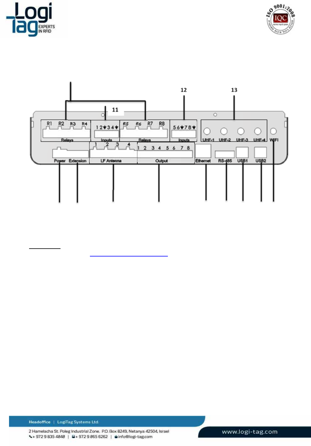
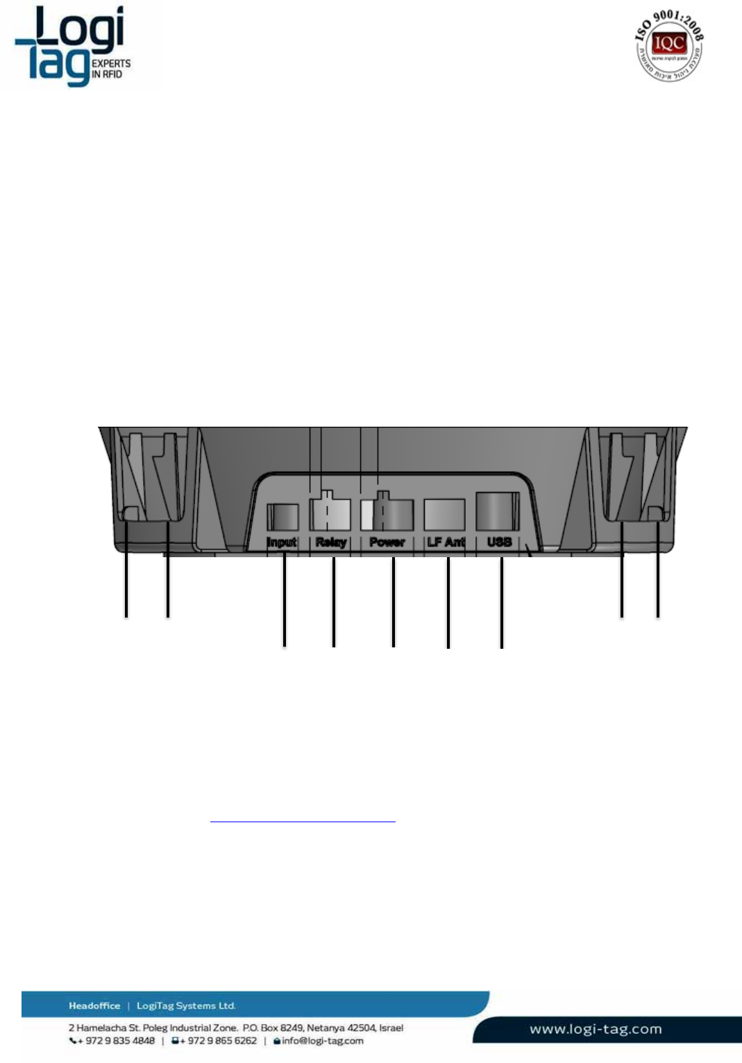
Wiringinstructions
Connections:
1.
Relays1‐8‐seeRelay(Drycontact)connectionsection.
2.
Power–connecttheunittothepowersocketbyusing24vadaptor
3.
Extension–useforboardhardwareextensions
4.
LFantennas–connecttheLFcableantennatoeachoneoftheavailableports1‐4
5.
Output–optiontooperateloadsat24Vwithsoftwarerulesoptions.
6.
Ethernet–connectaCAT5EEthernetcable
7.
RS‐485‐comunicationportconnector
8.
USB1‐connectaUSBcabletocommunicatewiththeLowlevelcontroller
9.
USB1‐connectaUSBcabletocommunicatewiththeHighlevelcontroller
10.
WI‐FI‐connectorforWIFIantenna
11,12.Input1‐4;5‐8
13.
UHFantennas–connecta433MHzantennastoUHF1‐3,UHF4canbeeither:
‐
916MHz(USA,IL)
‐
869.85Mhz(Europe)
1
2
3
4
5
12 13
678
9
10
11
LT‐D‐0211rev16
Page|17
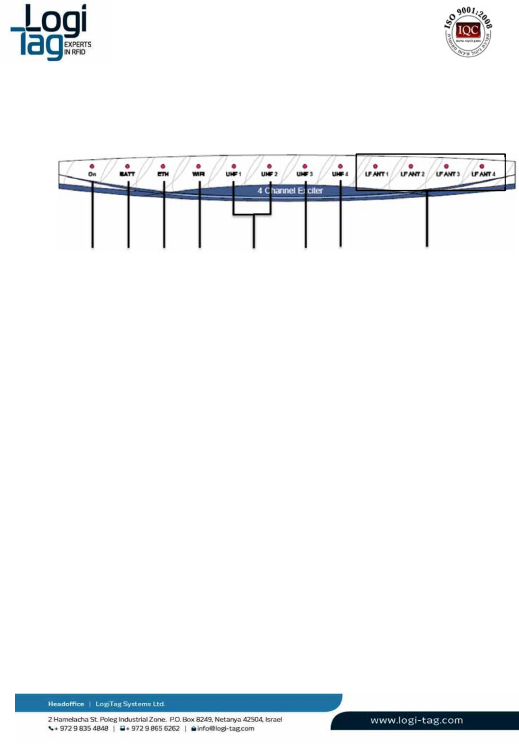
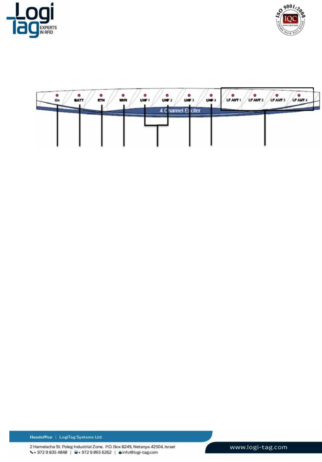
Frontpanelindications
LEDindication:
1.
On–LEDindicationforpowerconnection
2.
Batt‐LEDindicationforabatteryconnectedandworking
3.
ETH‐LEDindicationforETHconnectionestablished
4.
Wi‐Fi‐LEDindicationforWI‐FIconnectionestablished
5.
UHF1,2–LEDindicationfortransmittingandreceivingdatatoandfromtags
6.
UHF3‐LEDindicationfortransmittingandreceivingdatatoandfromtagsensor
7.
UHF4‐LEDindicationforcommunicationwithabasestationunit.
8.
LFant1‐4–LEDindicationofantennaactivatedontheunit
Warnings
Battery‐Riskofexplosionifbatteryisexposedtoextremeheat
Exposedwires–Riskofshockwhentouchingexposedwires
WaterExposure‐Riskofshockwhentouchingtheunitexposedtowater
1
2
3
4
5678

LT‐D‐0211rev16
Page|18
3.3. GateExciterGPRS
TheGateLocatorGPRSfunctionalizesasacombinationofBaseStationandGateLocator.Canbethe
managementunitandalsodirectoperationandcontrolofRFIDtags.
Unitcanmanagethesubunits–gatelocators.Itcarriesoutthefollowingfunctionalities:
Managementunit–thedatathatisreceivedonthegatelocatorsistransferredtotheunit
withanindicationonwhichunitsendsthedata.
Theunitisabletosendconfigurationinfothegatelocatorsvia869.85/916MHz(area
dependent)
Transferringdata–theunitreceivesovertheUHFband.themessagestransmittedbythe
tagstothegatelocatorandthentotheGateExciterGPRS.Itcansendthemaresponse(to
acknowledgethereception);senddatatoamainserver,triggerlocalhardwarethroughdry‐
contactinterfacesorstartacontinuouscommunicationsessionwiththetag.
GenerateRF‐Zonesusinganinternal125KHztransmitter.Eachoftheunit'schannelscarries
auniquenumberasanidentifiertothelocation/areawheretheRF‐Zoneisoperates. The
devicehas4LFantennaports,onlyoneworksatatime.
Operateslogicalrules:basedonevents(tagdetection,sensordetection,locationdecision,
etc.)thattheunitsdetectsitactivatesactions(I/O,parameterupdate,etc.)
Functionasarepeatertotag’stransmissions,relayingittowardtheBase‐Stationunit.
Independentunit–theunitcanfunctionandconnecttoaserver.
GateExciterGPRScanconnectthecustomercomputer/managementsystemviaEthernet,GPRSorWIFI.
NotethattheGateExciterGPRSinstallationmustbeseparatedfromelectricityand
communicationinfrastructure
Technicaldetails:
Power
Powersupply24VDC
Maximumcurrentconsumption2.5A
Backupbattery9Ahrechargeable
FusePTC2.5A
Airinterface
UHFinterface3X433MHz,1X869.85/916MHz
UHFrangeUpto25m
LFinterface4X125KHz
LFrange0–10m
Hostinterface
RS2322XRS232(115.2Kbps)
Ethernet10/100Mbps
Wi‐Fi802.11b/g,up‐to54Mbps (optional)
GPRSGPRSconnection(optional)
I/Ointerfaces

LT‐D‐0211rev16
Page|19
Relays8Xnormallyopenrelaycontacts.250VAC/5Aeach
Inputs8Xlowlevelsignalanalog/digitalinputs
Outputs8Xgeneraluseoutputs,V=24VImax=20mAforeach
LEDs12XLEDs
Memory
EEPROM128MB
Flash128MB
Environmental
Operationaltemperature‐10°C÷+45°C
Storagetemperature‐20°C÷+70°C
Dimensionsandweight
DimensionsLXWXH‐275X159X57mm
Weight1.29Kg
LFAntennaspowersettings:
ForeachLFantennayoucanconfigureviasoftware,theoutputpoweratrangeofbetween10to100%.
Backupbatteryreplacements:
Warnings:
6. InanycasebeforereplacingadviceyourlocalsuppliertechnicalsupportorLogitagcustomers
support.
7. Onlyauthorizedtechniciancanreplacebattery.
8. Disconnecttheunitfromthepowersource.
9. UsebatterywhichapprovedbyLogitagforassemblyattheunit.
10. Batterymustberechargeabletype3.7‐4.2V.
Replacementprocedure:
Disconnecttheunitfrompowersourceandallothercablesconnectiontotheconnectorspanel.
Openthe4screwsofthedevice.
Removethebattery
Connectthenewbattery
Installationinstructions
Installationpositions:
Vertically–placedonashelforatable,antennasadjustedandpointedtotheceiling.
Wallmount‐Screwedtothewallbyusingthesidebrackets,antennasadjustedandpointedto
theceiling.
PowerConnection:
Connectthepowerconnectiontothepowersocketandtotheunitat"power"connection.
Relayandantennas:
Relayconnection–seeRelay(Drycontact)connectionsection.
Antennas–connecttheantennastoanyportavailableonLFantennasports1‐4.

LT‐D‐0211rev16
Page|20
Serviceinstructions
Theunitmustbekeptawayfrommetal,heat(above60
°
Celsius\140Fahrenheit)andwater.
Cleaninginstructions
Nocleaningisrequired
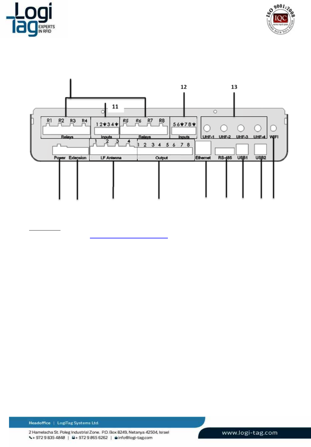
Wiringinstructions
Connections:
1.
Relays1‐8‐seeRelay(Drycontact)connectionsection.
2.
Power–connecttheunittothepowersocketbyusing24vadaptor
3.
Extension–useforboardhardwareextensions
4.
LFantennas–connecttheLFcableantennatoeachoneoftheavailableports1‐4
5.
Output–optiontooperateloadsat24Vwithsoftwarerulesoptions.
6.
Ethernet–connectaCAT5EEthernetcable
7.
RS‐485‐comunicationportconnector
8.
USB1‐connectaUSBcabletocommunicatewiththeLowlevelcontroller
9.
USB1‐connectaUSBcabletocommunicatewiththeHighlevelcontroller
10.
WI‐FI‐connectorforWIFIantenna
11.
11A,11BInput1‐4;5‐8
1
2
3
4
5
11B
12
678
9
10
11A
13

LT‐D‐0211rev16
Page|21
12.
UHFantennas–connecta433MHzantennastoUHF1‐3,UHF4canbeeither:
916MHz(USA,IL)
869.85Mhz(Europe)
13.
GPRS
Frontpanelindications
LEDindication:
9.
On–LEDindicationforpowerconnection
10.
Batt‐LEDindicationforabatteryconnectedandworking
11.
ETH‐LEDindicationforETHconnectionestablished
12.
Wi‐Fi‐LEDindicationforWI‐FIconnectionestablished
13.
UHF1,2–LEDindicationfortransmittingandreceivingdatatoandfromtags
14.
UHF3‐LEDindicationfortransmittingandreceivingdatatoandfromtagsensor
15.
UHF4‐LEDindicationforcommunicationwithabasestationunit.
16.
LFant1‐4–LEDindicationofantennaactivatedontheunit
Warnings
Battery‐Riskofexplosionifbatteryisexposedtoextremeheat
Exposedwires–Riskofshockwhentouchingexposedwires
1
2
3
4
5678
LT‐D‐0211rev16
Page|22
WaterExposure‐Riskofshockwhentouchingtheunitexposedtowater
3.4. 4ChannelExciter
The4channelexciterisaunitthathas2mainfunctions:
GenerateRF‐Zonesusinganinternal125KHztransmitter.Eachofthe4channelexciter's
channelscarriesauniquenumberasanidentifiertothelocation/areawheretheRF‐Zoneis
operates.
Functionasarepeatertotag’stransmissions,relayingittowardtheBase‐Stationunit.
Independentunit–thegatelocatorcanfunctionandconnecttoaserver.
Technicaldetails:
Power
Powersupply24VDC
Maximumcurrentconsumption2.5A
Backupbattery9Ahrechargeable
Fuse2.5APTC
Airinterface
UHFinterface3X433MHz,1X869.85/916MHz
UHFrangeUpto25m
LFinterface4X125KHz
LFrange0–10m
Hostinterface
RS2322XRS232(115.2Kbps)
EthernetNone
Wi‐FiNone
GPRSNone
I/Ointerfaces
Relays8Xnormallyopenrelaycontacts.250VAC/5Aeach
Inputs8Xlowlevelsignalanalog/digitalinputs
Outputs 8Xgeneraluseoutputs,V=24VImax=20mAforeach
LEDs12XLEDs
Memory
EEPROM128MB
Flash128MB
Environmental
Operationaltemperature‐25°C÷+60°C
Storagetemperature‐45°C÷+85°C
Dimensionsandweight
DimensionsLXWXH‐275X159X57mm
Weight1.29Kg

LT‐D‐0211rev16
Page|23

LT‐D‐0211rev16
Page|24
LFAntennaspowersettings:
ForeachLFantennayoucanconfigureviasoftware,theoutputpoweratrangeofbetween10to100%.
Backupbatteryreplacements:
Warnings:
11. InanycasebeforereplacingadviceyourlocalsuppliertechnicalsupportorLogitagcustomers
support.
12. Onlyauthorizedtechniciancanreplacebattery.
13. Disconnecttheunitfromthepowersource.
14. UsebatterywhichapprovedbyLogitagforassemblyattheunit.
15. Batterymustberechargeabletype3.7‐4.2V.
Replacementprocedure:
Disconnecttheunitfrompowersourceandallothercablesconnectiontotheconnectorspanel.
Openthe4screwsofthedevice.
Removethebattery
Connectthenewbattery
Serviceinstructions
Theunitmustbekeptawayfrommetal,heat(above60°Celsius\140Fahrenheit)andwater.
Cleaninginstructions
Nocleaningisrequired
LT‐D‐0211rev16
Page|25
Wiringinstructions
Connections:
1.
Relays1‐8‐seeRelay(Drycontact)connectionsection.
2.
Power–connecttheunittothepowersocketbyusing24vadaptor
3.
Extension–useforboardhardwareextensions
4.
LFantennas–connecttheLFcableantennatoeachoneoftheavailableports1‐4
5.
Output–optiontooperateloadsat24Vwithsoftwarerulesoptions.
6.
Ethernet–connectaCAT5EEthernetcable
7.
RS‐485‐comunicationportconnector
8.
USB1‐connectaUSBcabletocommunicatewiththeLowlevelcontroller
9.
USB1‐connectaUSBcabletocommunicatewiththeHighlevelcontroller
10.
WI‐FI‐connectorforWIFIantenna
11,12.Input1‐4;5‐8
14.
UHFantennas–connecta433MHzantennastoUHF1‐3,UHF4canbeeither:
‐
916MHz(USA,IL)
‐
868Mhz(Europe)
1
2
3
4
5
12 13
678
9
10
11
LT‐D‐0211rev16
Page|26
Frontpanelindications
LEDindication:
17.
On–LEDindicationforpowerconnection
18.
Batt‐LEDindicationforabatteryconnectedandworking
19.
ETH‐LEDindicationforETHconnectionestablished
20.
Wi‐Fi‐LEDindicationforWI‐FIconnectionestablished
21.
UHF1,2–LEDindicationfortransmittingandreceivingdatatoandfromtags
22.
UHF3‐LEDindicationfortransmittingandreceivingdatatoandfromtagsensor
23.
UHF4‐LEDindicationforcommunicationwithabasestationunit.
24.
LFant1‐4–LEDindicationofantennaactivatedontheunit
Warnings
Battery‐Riskofexplosionifbatteryisexposedtoextremeheat
Exposedwires–Riskofshockwhentouchingexposedwires
WaterExposure‐Riskofshockwhentouchingtheunitexposedtowater
1
2
3
4
5678

LT‐D‐0211rev16
Page|27
3.5. 1ChannelExciter
The1channelslocatorisaunitthathas2mainfunctions:
Generate1RF‐Zoneusinganinternal125KHztransmitter.The1channelexciter'schannel
carriesauniquenumberasanidentifiertothelocation/areawheretheRF‐Zoneisoperates.
Functionasarepeatertotag’stransmissions,relayingittowardtheBase‐Stationunit.
Independentunit–thegatelocatorcanfunctionandconnecttoaserver.
Technicaldetails:
Power
Powersupply24VDC
Maximumcurrentconsumption0.6A(recommendedtouse24V1.5Aminimumpower
supply)
BackupbatteryNone
Fuse1.6APTC
Airinterface
UHFinterface3X433MHz,1X869.85/916 MHz
UHFrangeUpto25m
LFinterface1X125KHz
LFrange0–10m
Hostinterface
USB1XRS232(115.2Kbps)
EthernetNone
Wi‐FiNone
GPRSNone
I/Ointerfaces
Relays1normallyopenrelaycontacts.250VAC/5Aeach
Inputs1lowlevelsignalanalog/digitalinputs
LEDs6XLEDs
Memory
EEPROM128MB
Flash128MB
Environmental
Operationaltemperature‐10°C÷+45°C
Storagetemperature‐20°C÷+70°C
Dimensionsandweight
DimensionsDiameter185mmHeight60mm
Weight0.48Kg
LT‐D‐0211rev16
Page|28
LFAntennaspowersettings:
FortheLFantennayoucanconfigureviasoftware,theoutputpoweratrangeofbetween10to
100%.
Serviceinstructions
Theunitmustbekeptawayfrommetal,heat(above60
°
Celsius\140Fahrenheit)andwater.
Cleaninginstructions
Nocleaningisrequired
Wiringinstructions
Connections
1,2,8,ConnectaUHF433MHzantenna
9,canbeeither:
‐
916MHz(USA,IL)
‐
868Mhz(Europe)
3.
Input–
4.
Relay‐seeRelay(Drycontact)connectionsection.
5.
Power–connecttheunittothepowersocketbyusing24vadaptor
6.
LFantennas–connecttheLFcableantennatotheport–whenconnectingtheexternal
antennatothisport,theinternalantennawillbedeactivated
7.
USB–connectaUSBcabletoconnecttothelowlevelcontroller.
3
456 7
12
8
9

LT‐D‐0211rev16
Page|29
Frontpanelindications:
1. Poweron
2. Tagidentifier
3. ReceiveUHFfromtags
4. TransmitUHFtotags
5. UHFRx\Txtosensortag
6. CommunicatingwithBasestation/4channelExciter
Warnings
Exposedwires–Riskofshockwhentouchingexposedwires
WaterExposure‐Riskofshockwhentouchingtheunitexposedtowater
LT‐D‐0211rev16
Page|30
3.6. RemoteDoorindicator
TheRemotedoorindicatorfunctionsasawirelessLEDsdriverdevice,activatedremotelybyUHF
commandfromthebasestation\GateLocator.
Technicaldetails:
Power
Powersupply24VDC
Maximumcurrentconsumption0.3A
Backupbattery500mAhrechargeable
Fuse0.5APTC
Airinterface
UHFinterface1X433MHz
UHFrangeUpto25m
LFinterfaceNone
LFrangeNone
Hostinterface
RS232None
EthernetNone
Wi‐FiNone
GPRSNone
I/Ointerfaces
Relays1normallyopenrelaycontacts.30VDC/1A–notforuse
InputsNone
LEDsExternalconnectiontoLEDsdevice,upto4highcurrent
LEDs;Eachcandriveupto200mA
Memory
EEPROM1MB
FlashNone
Environmental
Operationaltemperature‐10
°
C÷+45
°
C
Storagetemperature‐20°C÷+70°C
Dimensionsandweight
DimensionsLXWXH‐141X67X38mm
Weight0.13

LT‐D‐0211rev16
Page|31
Connectors:
LT‐D‐0211rev16
Page|32
Backupbatteryreplacements
ContactyourlocalsupportorLogitagcustomersupport.
Installationinstructions
Thisdeviceiswallmount–connecttheenclosuretothewallusing4screws.
Serviceinstructions
Theunitmustbekeptawayfrommetal,heat(above60°Celsius\140Fahrenheit)andwater.
Cleaninginstructions
Nocleaningisrequired
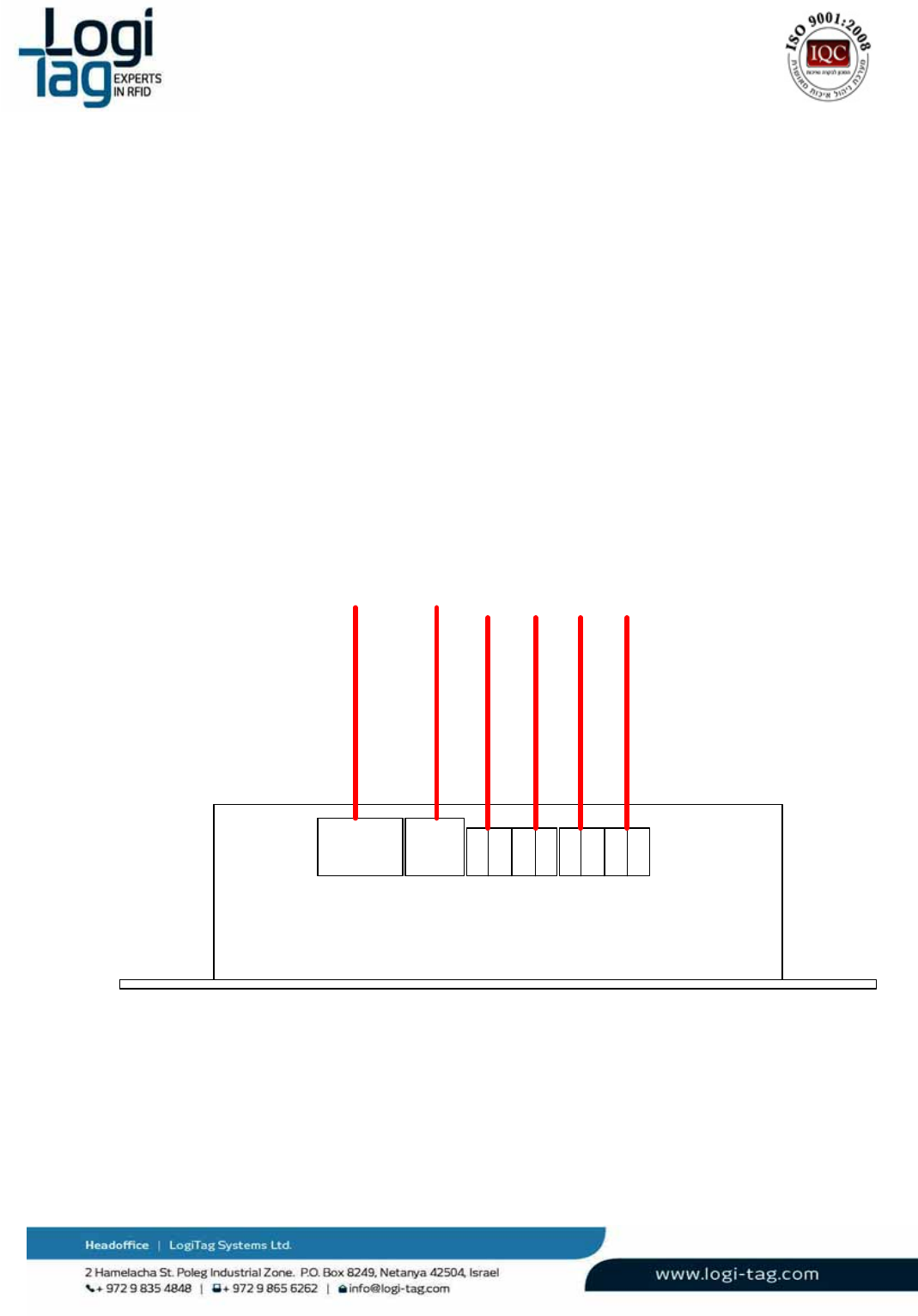
Wiringinstructions
Power
supply General
userelay
2xLED
driver
2xLED
driver
12
3456
1. powersupply(leftpin+Vcc,rightpinground)
2. generaluserelay,normallyopencontacts–notforuse
3. leddriver1(leftpincathode,rightpinanode)
4. leddriver2(leftpincathode,rightpinanode)
5. leddriver3(leftpincathode,rightpinanode)
6. leddriver4(leftpincathode,rightpinanode)

LT‐D‐0211rev16
Page|33
Warnings
Battery‐Riskofexplosionifbatteryisexposedtoextremeheat
Exposedwires–Riskofshockwhentouchingexposedwires
WaterExposure‐Riskofshockwhentouchingtheunitexposedtowater
LT‐D‐0211rev16
Page|34
3.7. LFantennas
LFantennageneratesRFIDzonesbytransmittinginafrequencyof125KHzandsendingdata.By
generatingtheRFzones,atagthatisintherangeofthedetectionareaoftheantenna,isexcitedand
receivesdatatransferredfromtheunitthroughtheRFIDfieldandeventuallytothetag.Oncethetagis
excited,thetagstartstotransmitonUHFband,directlytothemainunit.Afterthetaghastransmitted
totheunitandreceivingprocesshasbeenmade,theunitsendsaconfirmationsignalonUHFbandto
thetagandconfirmingthatthedatahasarrived.
Theantennainstallationshouldbeinthecorrectangle(describedinthenextsection),whichaffectsthe
receptionareaofthetags.
Bylocatingtheantennaincorrectposition,thesystemenablesawidedetectionrange.
3.6.1 Ceilingantenna
Technicaldetails:
Airinterface
LFinterface125KHz
LFrange0–10m
Environmental
Operational
temperature
‐10°C÷+45°C
Storage
temperature
‐20°C÷+70°C
Dimensions
andweight
DimensionsDiameter178mmHeight56.5mm
Weight0.43Kg

LT‐D‐0211rev16
Page|35
Installationinstructions
Theantennacanbeinstalledinoneofthenextoptions:
1. Mountedtothewall–openingthetopoftheboxandinsertingtwoscrews
2. Shelf–installedonashelfextension,antennainhorizontalangle
Serviceinstructions
TheAntennamustbekeptawayfrommetal,heat(above60°Celsius\140Fahrenheit)andwater.
Cleaninginstructions
Nocleaningisrequired
Wiringinstructions
ConnecttheantennatotheLFportandtotheunit
Warnings
Exposedwires–Riskofshockwhentouchingexposedwires
WaterExposure‐Riskofshockwhentouchingtheunitexposedtowater

LT‐D‐0211rev16
Page|36
3.6.2 Doorantenna
Technicaldetails:
Airinterface
LFinterface125KHz
LFrange 0– 5m
Environmental
Operational
temperature
‐10°C÷+45°C
Storage
temperature
‐20°C÷+70°C
Dimensions
andweight
DimensionsDiameter100mmHeight43mm
Weight0.16Kg

LT‐D‐0211rev16
Page|37
Installationinstructions
Theantennacanbeinstalledinoneofthenextoptions:
1. Mountedtothewall–openingthetopoftheboxandinsertingtwoscrews
2. Shelf–installedonashelfextension,antennainhorizontalangle
3. Antennaholder–connecttheantennaholderbyopeningthetopoftheantennaboxand
connectingtheholder.Afterconnectedtotheantennaconnecttheholdertothewall.
Serviceinstructions
TheAntennamustbekeptawayfrommetal,heat(above60°Celsius\140Fahrenheit)andwater.
Cleaninginstructions
Nocleaningisrequired
Wiringinstructions
ConnecttheantennatotheLFportandtotheunit
Warnings
Exposedwires–Riskofshockwhentouchingexposedwires
WaterExposure‐Riskofshockwhentouchingtheunitexposedtowater
LT‐D‐0211rev16
Page|38
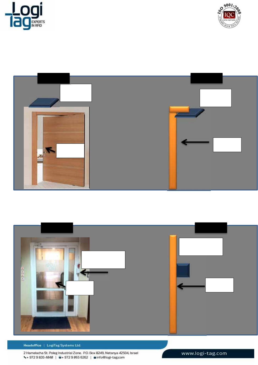
3.6.3 Antennainstallationexamples
1.
LFantennainstallationondoor–facingdown
2.
LFantennainstallationondoor–gateentrance
Entrance
LFantenna
Gateinstallation
Entrance
LFantenna
Facingfloor
LFantenna
Facingfloor
Entrance
LFantenna
Gateinstallation
Entrance
FrontviewSideview
FrontviewSideview

LT‐D‐0211rev16
Page|39
3.7 Tags
3.7.1 General
TheLogiTracktagsaresmallandsophisticatedtransceivers.
ALogiTracktagistypicallydormantuntil1ofthefollowinghappens:
1. ThetagisexcitedwhenenteringaRF‐ZonegeneratedbytheLogiTrackinfrastructure(Base‐
stationsorexciters).ThisRF‐Zoneiscreatedusingasignalin125KHz,whichthetag
receives.Asaresult,thetagwillwake‐up,andtransmitoverUHFchannel(433MHz)its
uniqueidentityandtheidentityoftheRF‐Zoneitjustenteredinto.
AftersendingthemessageovertheUHFchannel,theGatelocatorisabletoexchangedata
withthetagthroughdirect,bi‐directionalcommunication.
2. ThetagtakesthedecisiontosendamessageovertheUHFbandduetointernaldecision
(usuallysensor/timerbased),oruserinteraction.Forexample:
a. Theuserpressedabuttononthetag
b. Thetemperaturesensedbythesensorexceedthethresholdandrequiresraisingan
alarm
c. Motionwasdetectedbythesensor
d. Tampering/removalwasdetectedbythesensor
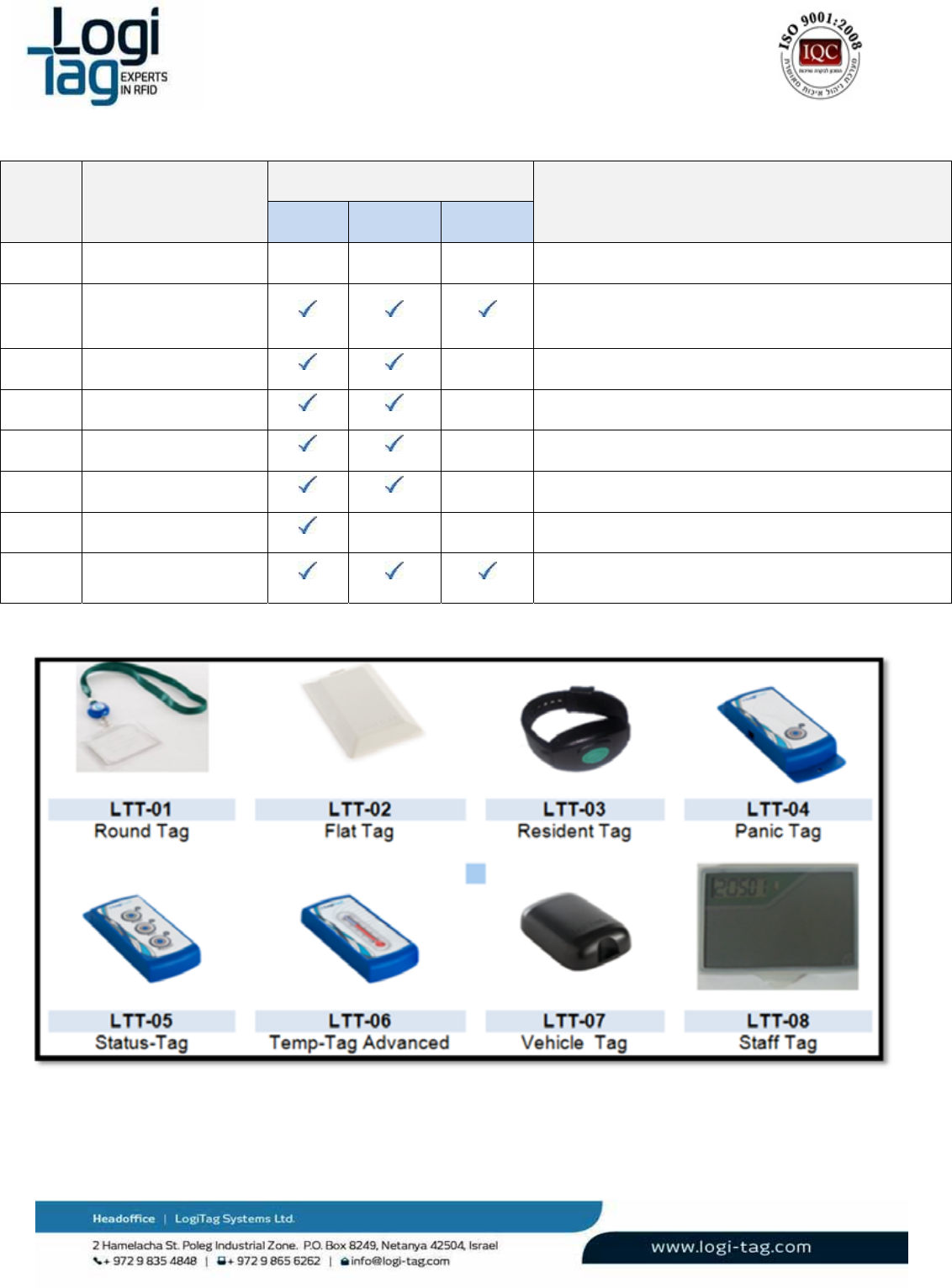
Thereareseveraltagoptions–differenttagelectronicsindifferentplasticenclosure.Everytagcanbe
usedinanyapplicationwhereitdeliverstherequiredperformancesandoperability,yetthemajority
wasdesignedtoanswerspecificapplications.
LT‐D‐0211rev16
Page|40
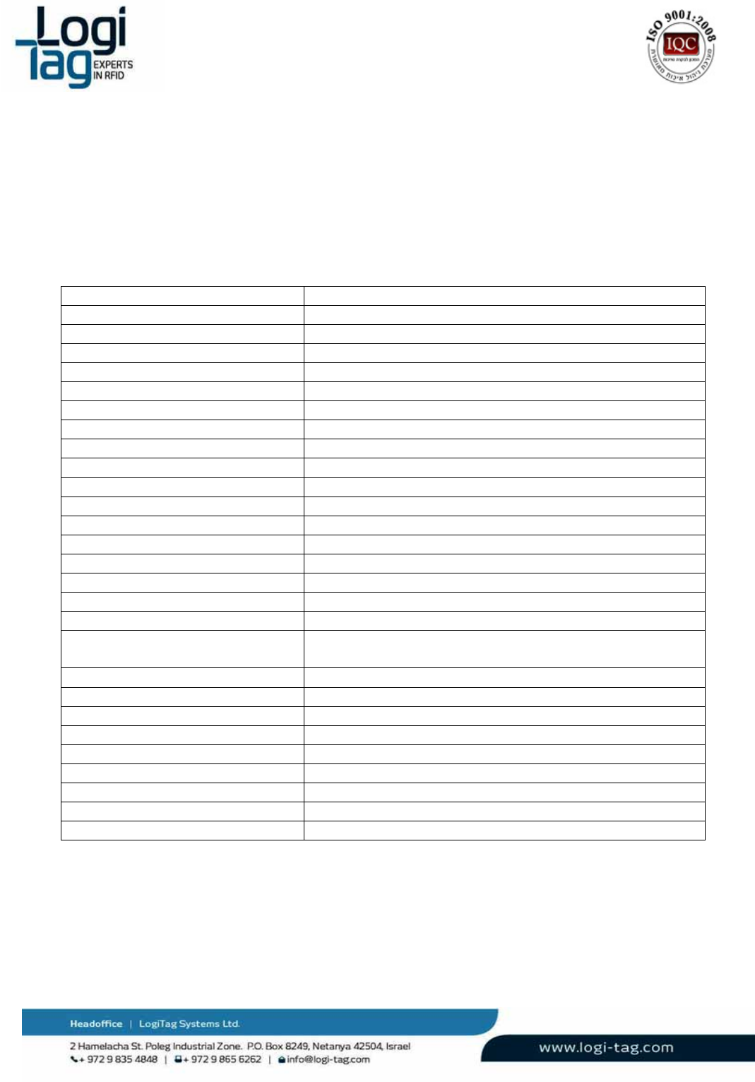
# ITEM SENSORS DESCRIPTION
Motion Tamper Buzzer
LTT-01 Round Tag Designed for covert attachment to visitor badge.
LTT-02 Asset Tag NG
New design, with cradle, all sensors and internal
buzzer
LTT-03 Resident tag
Wristband tag with tamper detection and panic button
LTT-04 Asset tag – Panic
Asset tag with single button
LTT-05 Asset tag - Status
Asset Tag with 3 buttons for general status indications
LTT-06 Temp Tag Advanced
Asset Tag with external PT-1000 temperature sensor
LTT-07 Vehicle tag IP65 vehicle tag, attached with screws or adhesive
LTT-08 Staff Tag
Staff ID tag with LCD, tag interrogation and 3 buttons
LT‐D‐0211rev16
Page|41
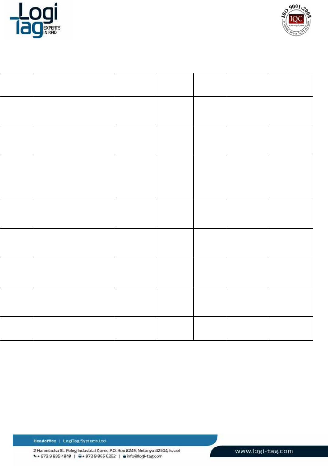
Tagstechnicaldetails
Tag Dimensions Battery
supply type
LF range UHF
range
Operational
temperature
Storage
temperature
LTT-01 Diameter 40mm
Height 12 mm
Primary
3V
3 meters 20 meters -10 - +45C -20 - +70C
LTT-02 LXWXH 85X54X7.2 mm Primary
3V
4.5 meters 25 meters -10 - +45C -20 - +70C
LTT-03
LXWXH
55X35X13 mm
Adult one-size fits all wrist
band (configurable)
Primary
3V
4.5 meters 9 meters -10 - +45C -20 - +70C
LTT-04 LXWXH
85X35X12 mm
Primary
3V
3.5 meters 25 meters -10 - +45C -20 - +70C
LTT-05 LXWXH
85X35X12 mm
Primary
3V
3.5 meters 25 meters -10 - +45C -20 - +70C
LTT-06 LXWXH
85X35X12 mm
Primary
3V
3.5 meters 25 meters -10 - +45C -20 - +70C
LTT-07 LXWXH
80X54X19 mm
Primary
3V
4 meters 25 meters -10 - +45C -20 - +70C
LTT-08 LXWXH
94X61X6.5 mm
Rechargeable
3.7-4.2V
3.5 meters 25 meters -10 - +45C -20 - +70C
Stafftagfunctionality:
LT‐D‐0211rev16
Page|42
3.7.2 Attachingtagstoobjects
Tagsattachedtoobjectsespeciallyelectricalobjectssuchascomputers,laptops,serverstrucksand
differentmetalssuchasmetalboardsandetc.,cancauseRFdisruptionontagstransmition.
Thedisruptionaffectstherangesandtransmitionofthetag.Inordertoadjustthesystemanoptimal
locationofthetagmustbelocatedbytestingthetagonavarietyoflocationsontopoftheobjectand
locatingtheoptimallocation.
ForexampletheoptimallocationonanIPADofanOptotypetag,isonthetoprightsideoftheIPAD.
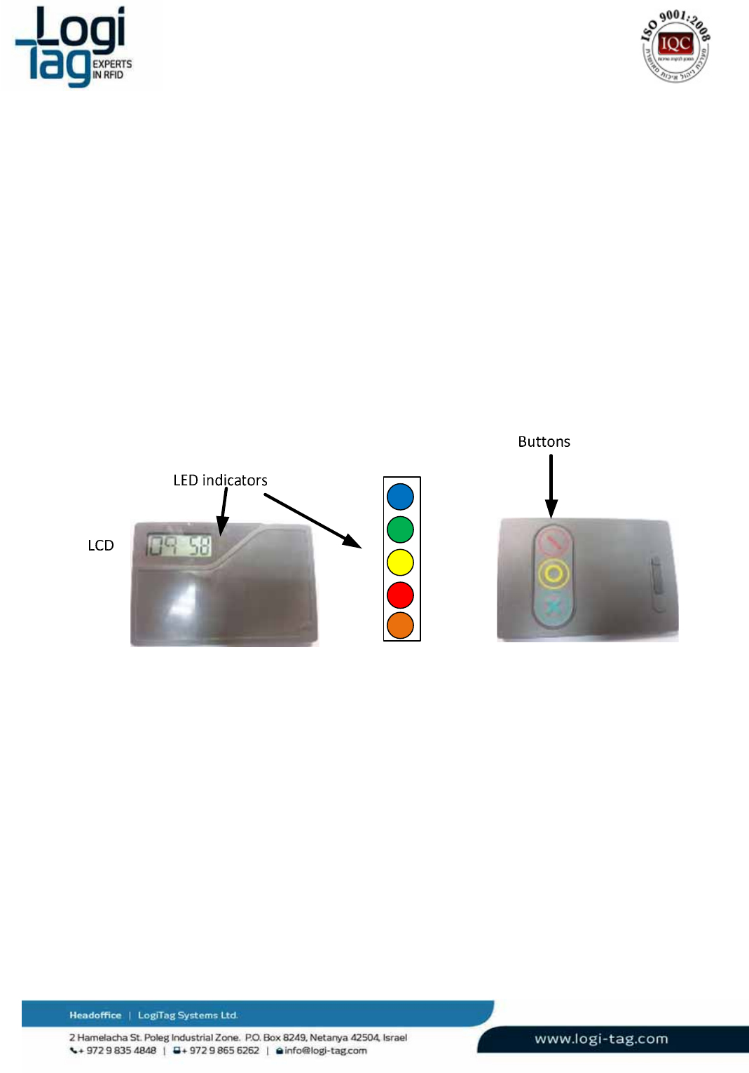
3.7.3 Stafftagfunctionality
Stafftaghasthefollowingbuttonsandindications:
Stafftaghastheabilitytoexciteanyothertagfrom1mradios(inadditiontotheregularfunctionality
explainedabove).
Whenpressingonthegreenbuttonthetagcreatinganearfieldsignalat125KHz.ifthereisother
transponderatitsrangethetagawakesandtransmittingtotheexciter/basestation.Thestafftagget
respondfromtheexciter/basestationwithmessageviewattheLCD.Messagecanbeanytypeofupto
5characters.
Whenpressingontheredandyellowbutton,thetagtransmitstheexciter/basestationtothesensor
antenna.
Ledindicators:
Blue–batterycharging
Green–replayfromexciter/basestation

LT‐D‐0211rev16
Page|43
Yellow–pressingonyellowbutton
Red–pressingonredbutton
Orange–LFsignaltransmitting/receiving
3.8 SystemRanges
Systemrangesisdividedforthreecategories:
LFrange–theLFantennasgeneratesRFzoneswhichcandetectandexciteRFIDtagsfrom0‐7
meters.Therangeschangewhenthetagsareattachedtoanelectrical\metalobject.
UHFrange‐theUHFrangeisgeneratedbytheunitthatreceivesthetagsinfoafterthetaghas
beendetectedandexcitedintheLFRFzone.Therangescanbefrom0‐25metersfromthetag
totheunit.
Therangeschangewhenthetagsareattachedtoanelectrical\metalobject.
UHFrangebetweenunits‐communicationbetweenthebasestationandthegatelocatoris
throughUHFband(whichisdifferentfromtheUHFbandofthetagtogatelocator).
Therangesarefrom0–25metersfromoneunittoanother.
Environmentaldisruptionssuchasconcretewithmetalsurroundingorelectricalenvironment
cancausereductionranges.
Condition/
Rangefield
ComponentsOpenspace
(meters)
Tagattachedto
electricalobject
(meters)
LFrangeAntennatag 0to7 0to4meters
UHFrangeTagGateLocator0to25meters0to10meters
UHFrangebetweenunitsGatelocatorBasestation0to25meters ‐‐‐‐‐‐‐‐‐‐‐‐‐‐‐
LT‐D‐0211rev16
Page|44
4.
GeneralWarningandinstructions
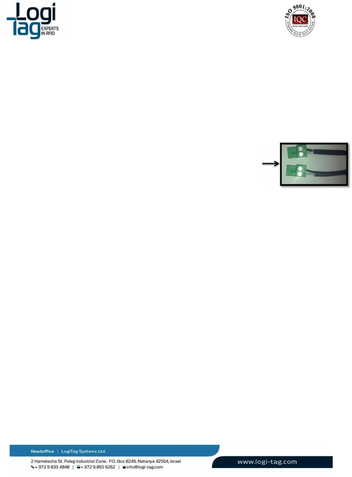
LFcable–permittedLFcabletypeis(providedbyLogiTagsystems):
GeneralConstruction:Onetwistedpair,cabledtogetherwithadrain‐wireandoverall
aluminum‐foilshielded.
ConductorSize:7x0.32mm
OuterJacketMaterial:FR‐PVC
OuterDiameter:4.6mmnom
o
Installtionofthecableandunitsmustbeseparatedfromcommunicationandelectricity
infrastructure
o
Donotconnectorcross2cables
o
Makesurethatcablepolarityisequalonbothendsasdescribedinthepicture
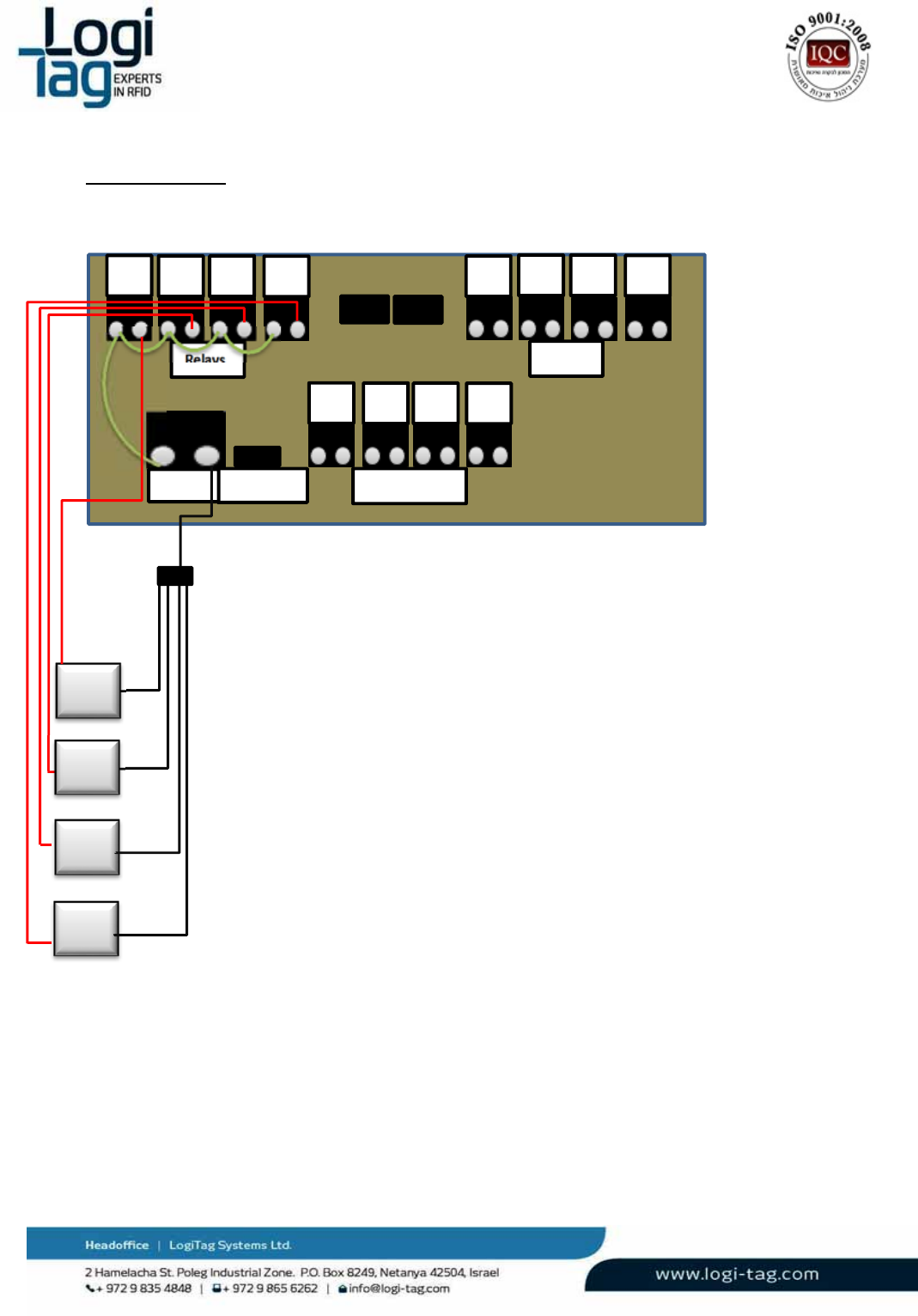
4.1 Relay(Drycontact)connection
Thesystemenablestoconnectadevicethatcanbeconnectedtothepowersupplyoftheunit(24V),
suchasabuzzeroralight,connectittotherelayconnectionandthedevicewillbeactivatedwhenatag
isdetectedintheLFantennarange.
Relaynumber1willbeactivatedwhenantennanumber1willdetecttags
Relaynumber2willbeactivatedwhenantennanumber2willdetecttags
Relaynumber3willbeactivatedwhenantennanumber3willdetecttags
Relaynumber4willbeactivatedwhenantennanumber4willdetecttags
Relaynumber5willbeactivatedwhenasensorwillsendasignaltotheunit
LT‐D‐0211rev16
Page|45
Connectionsketch:
R1R2R3R4
1234
R5R6R7R8
LFantenna
Power
Extension
RelaysRelays
+
‐
Power
Buzzer
Buzzer
Buzzer
Buzzer
+‐
LT‐D‐0211rev16
Page|46
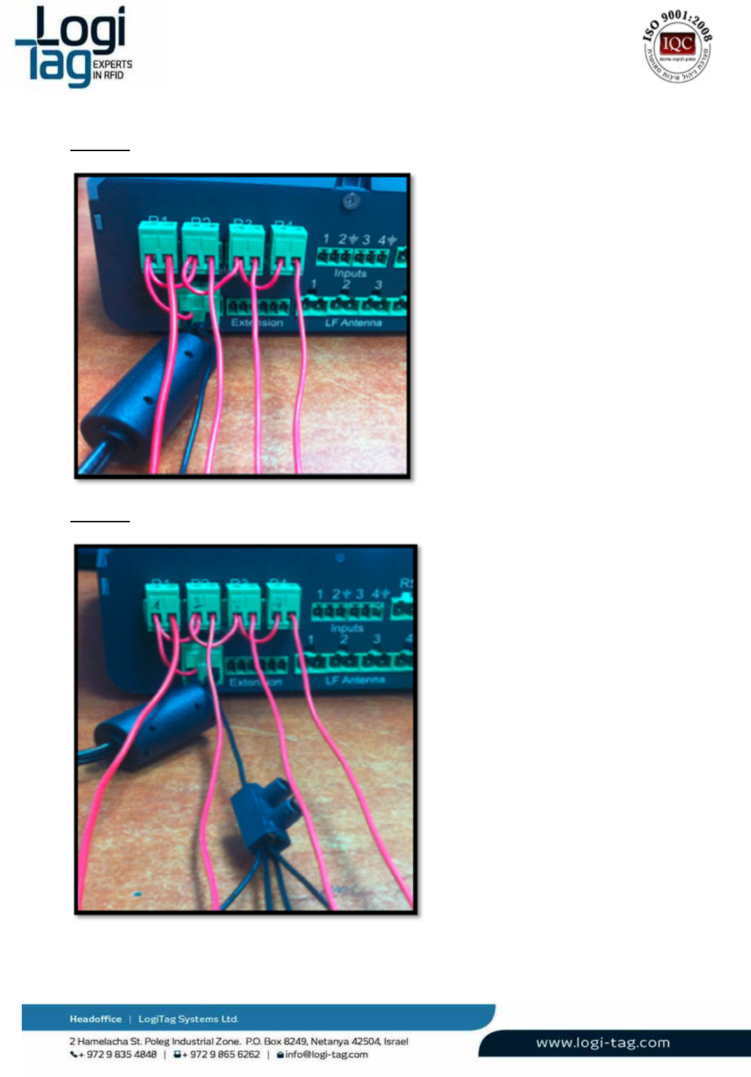
Picture1:
Picture2:
LT‐D‐0211rev16
Page|47
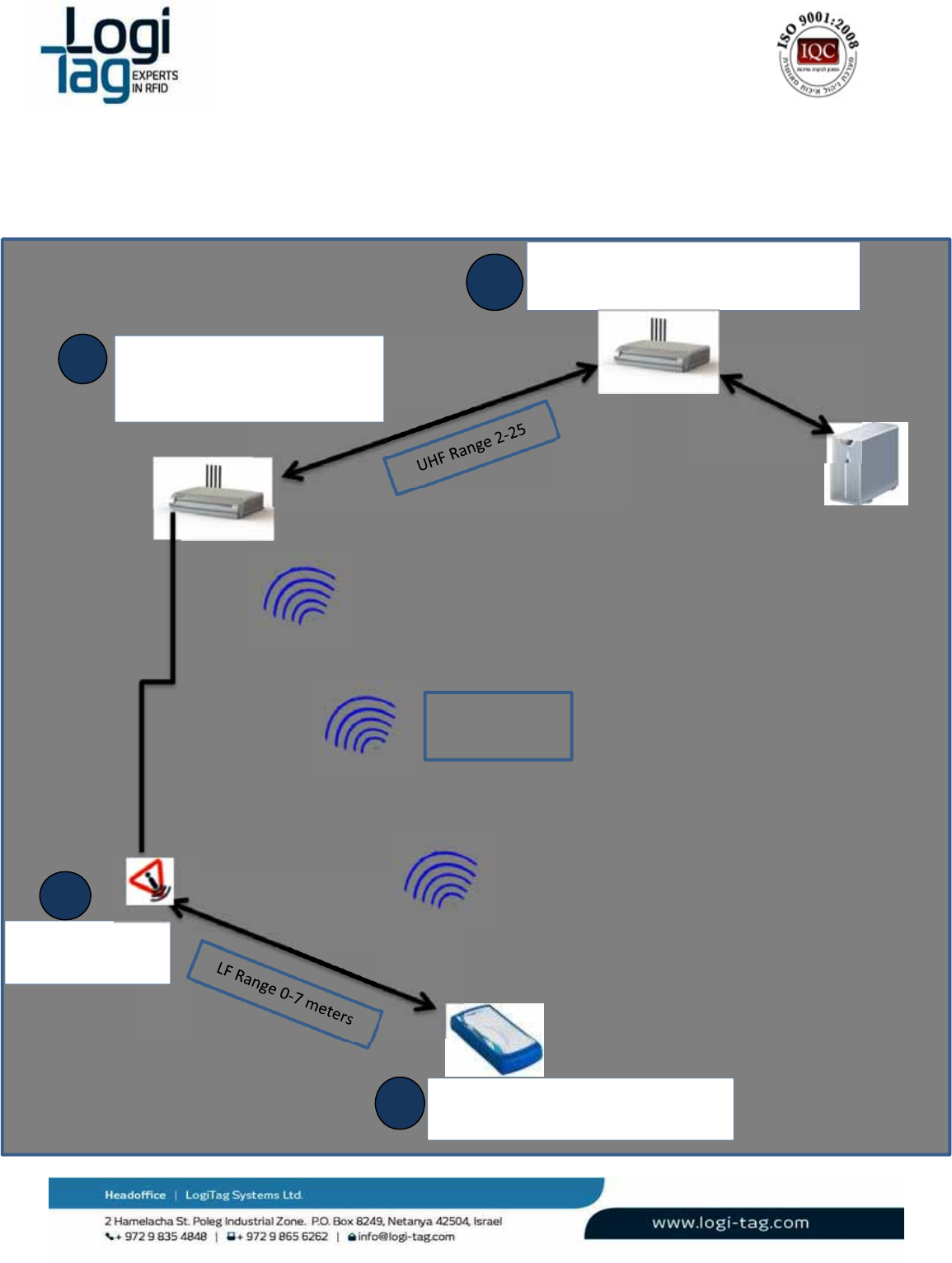
5.
Infrastructureanddataflowsketch
GateLocatorreceivestag’s
messageandretransmittothe
base‐station/pc
Gate Locator
Base-Station
Base‐StationReceivesmessagesfromgate
locatorandforwardtopc
Tagisexcitedandtransmitsitslocation
andidentityonUHFband
UHFRange0‐25
meters
1
2
125KhzRFSignal
excitesthetags
3
4
LT‐D‐0211rev16
Page|48
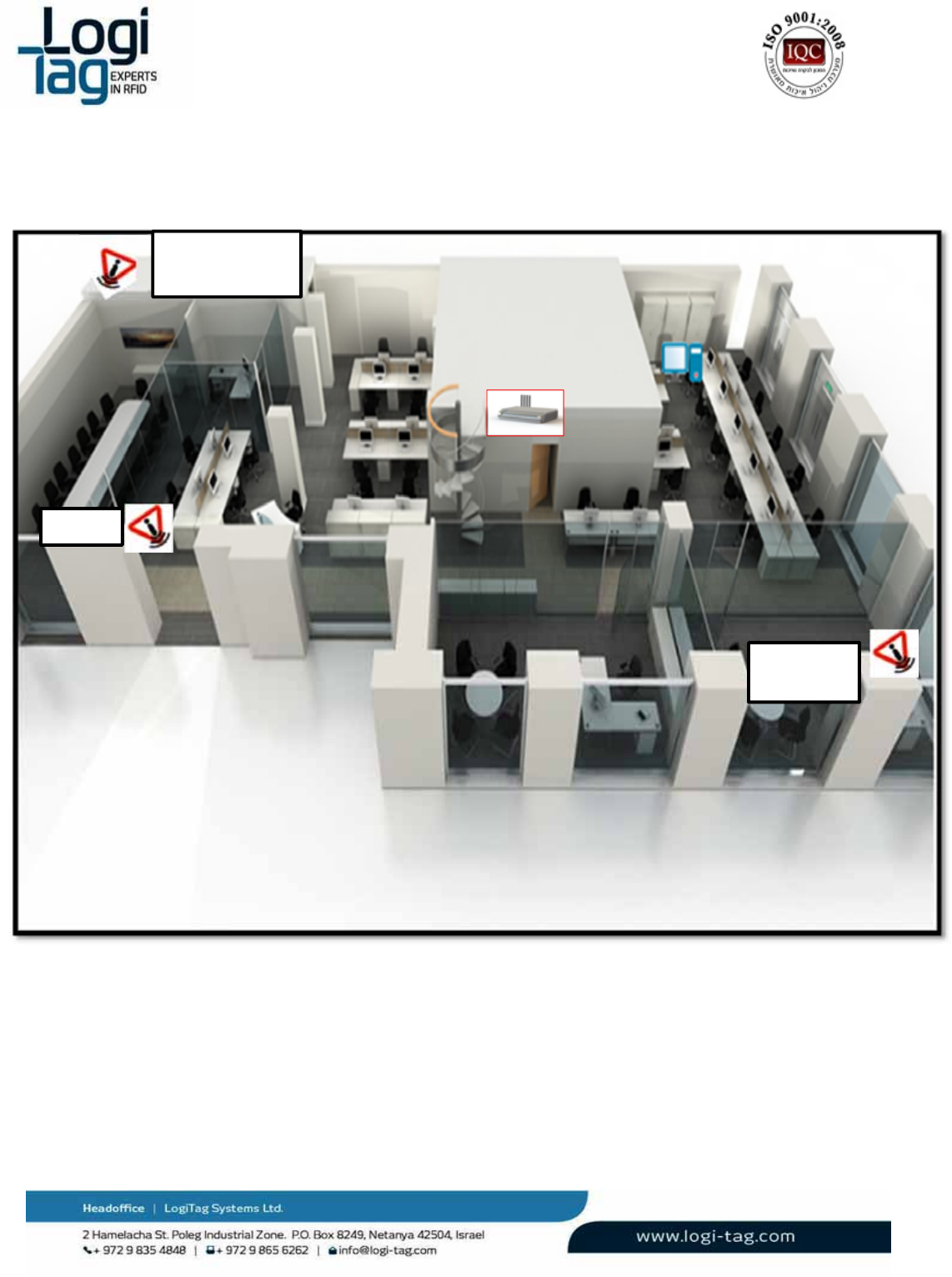
5.1 Siteinstallationexample
Gate Locator
Exit
Meeting
Room Exit
Emergency
Exit

LT‐D‐0211rev16
Page|49
6.
SoftwareInstallation
6.1 InstallingtheTechnician‐Station
EnsurethatthePCyouareabouttoinstallthesoftwareonisrunningWindowsXPorWindows
7,preferablyfromProfessionaleditionandup.
InstallonthecomputerMicrosoft.NETFramework4.0availablefromMicrosoft’swebsite.
Executetheinstallationfile“Setup.exe”
RunningtheTechnician‐Stationsoftware
Locatetheexecutablefile“LogiTrackTechStation”atthedesignateddestinationfolder.
Runtheexecutablefile
InterfacingwithaBase‐Station
ConnecttheUSBcabletotheUSB1connection.
ConnecttheUSBcabletoyourPC.
InstalltheUSBtoRS232converterdriverprovidedbyLogiTag(ifwindowshavenotinstalledthedriver
automatically)
6.2 SoftwareOperation
Afterlaunchingtheapplication,thewelcomescreenisshownfirst.
LT‐D‐0211rev16
Page|50
6.3 ApplicationStructure
TheTechnician‐Stationincludesthefollowingmodules,eachinaseparatetab:
“Connection”Tab–Enablesmanagingconnectionsto1ormoreBase‐Stations\GateLocators,
throughUSBconnection.
“BaseStationSetup”–Enablesconfigurationofeveryprogrammableparameterinaconnected
Base‐Station.ThetabalsoenablesconfiguringGateLocatorsthatarerelayedthroughevery
Base‐Station.
“TagSetup”–EnablesactivatingandconfiguringtheLogiTracktags,includingtheirspecific
sensorbasedfeatures.
“Enrollment”–Enablesdefiningassetsandpeoplewiththeirspecificidentifiersand
information,andassigningthemtoaspecifictag.
“Detection”–Showsalistofalltagscurrentlyreceivedbytheapplicationthroughanyofthe
connectedBase‐Stations.Thelistismanageableandcanbefilteredandsorted.
“BaseStationOperations”–EnablesinterfacingtheBase‐Station’sI/O.
“Reports”–Enablesreviewingreportsformoredetaileddata,andoptionallyexportthe
informationtoExcelfileformat.
“LOG”–ShowsrawdatareceivedfromconnectedBase‐Stations
“Administration”–Generalapplicationsettingsandinterfacingwith3rdpartysoftware
LT‐D‐0211rev16
Page|51
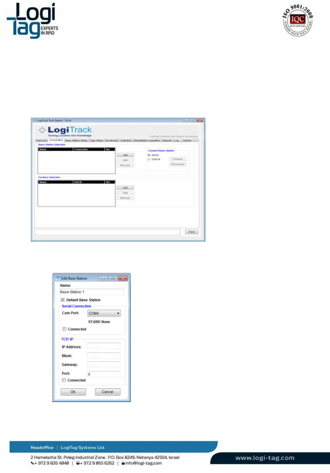
6.4 Connectingtoaunit
6.4.1 AddingaBase‐Station
ToaddaBase‐Station
SelecttheConnectiontabfromthetabslist
Thefollowingtabisdisplayed:
PresstheAddbutton.
Thefollowingwindowsappear:
SpecifythefollowingparametersfortheBase‐Stationyouareadding.
Name:SpecifiesanaliasfortheBase‐Stationyouareadding.

LT‐D‐0211rev16
Page|52
Defaultbase‐Station:CheckthisboxtomaketheBase‐Stationthedefaultoneintheapplication,
ifmorethan1isconnected.MakingaBase‐Stationthedefaultonewillundoanypreviously
selectedBase‐Stations.
SerialConnection
ComPort:Selectfromthedrop‐downlisttheCom‐PortonwhichtheBase‐Stationisconnected.
Connected–CheckthischeckboxtomarkthatConnectionisavalidconnectionmethod.
PressOKtofinishthefirststepinconnectinganewBase‐Station
6.4.2 AddingaGatelocator
FromtheConnectiontabpresstheAddbuttonlocatedattheExciterSelectionsection.
Thefollowingwindowappears
:
Choosethecomportandclickonconnectiftheunitisconnectedtothecomputer.
IftheunitisnotconnectedtheunitIDwillnotbesavedontheunit.
6.4.3 DefiningaunitIDtotheGateLocator
IfthisisthefirsttimeusingthisGateLocator,youmightwanttoassignitwithauniqueDevice‐IDfor
yoursystem:
ConnecttheGateLocatortoyourcomputerusingaUSBcable
SelecttheCom‐Portfromthedrop‐downlistandpresstheConnectbutton.
SettheExciterIDvaluetoauniquenumberandpresstheSavebutton.
Whenfinishedtheunitwillbesaved.Inordertoaddtheunittothebasestationmoveto"Base
Station"tabandperformthefollowing(notethatthebasestationhastobeconnected):
1. Fromthe“BaseStation”dropdownlist,selecttheBase‐StationthroughwhichtheExciteris
tocommunicate(nearestinstalledBase‐Station).
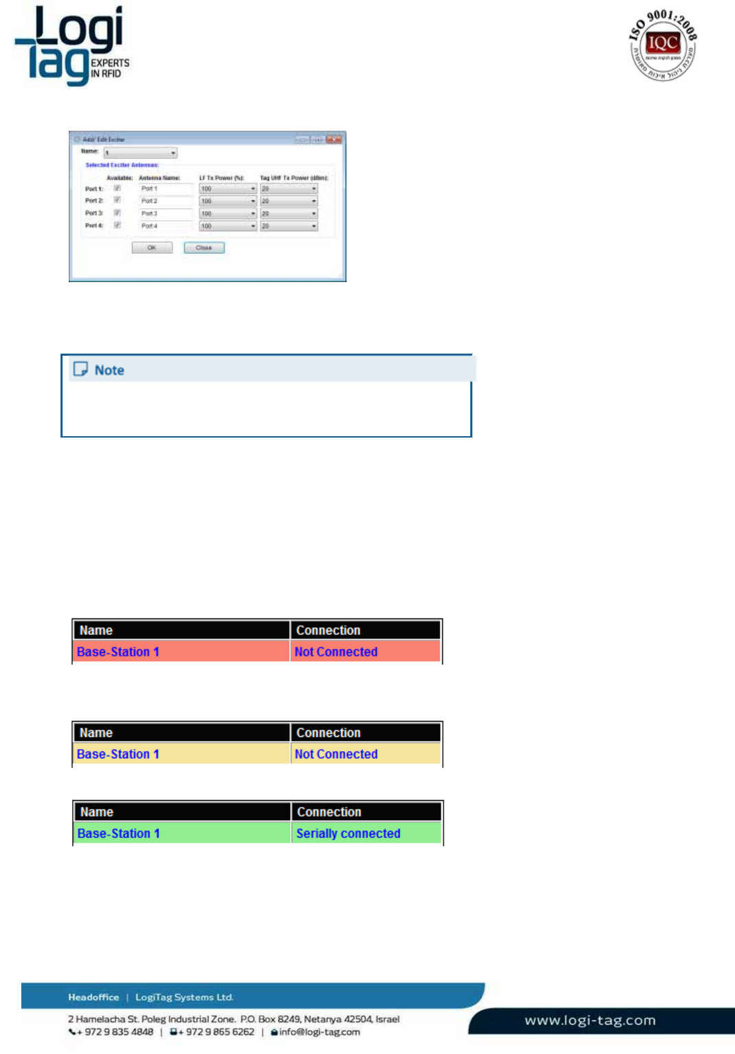
2. Pressthe“AddExciter”button.Thefollowingwindowappears:
LT‐D‐0211rev16
Page|53
3.
Fromthe“Name”drop‐downlist,selecttheExciteryouwishtoaddtothisBase‐Station
(onlyExcitersaddedaccordingtosteps1&2ofthissectionwillappearinthislist)and
configuretheexciter’sLFports.
FordetailedexplanationsonAntennaportsconfiguration,see
DefiningRF‐Zones(LFAntennas)inBaseStationConfiguration
sectionTab.
3.
Pressthe“OK”buttontofinishtheoperation.
4.
ClickSetbottominordertotransferthedatatothebasestation.
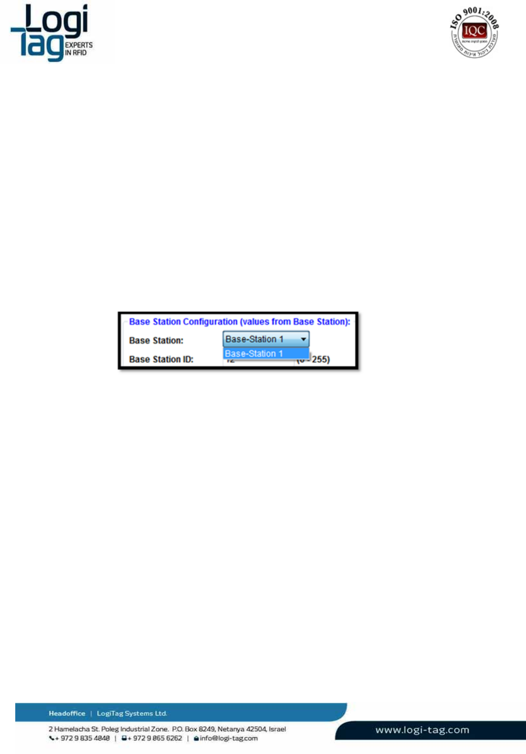
6.4.4 ViewingConnectivityStatus
TheBaseStationSelectionlistontheConnectiontabshowsalltheBase‐Stationsthatwereaddedtothe
applicationandtheircurrentconnectivitystatus.
Thepossibleconnectivitystatusesare:
“NotConnected”(Redbackground)–IndicatesthattheapplicationinunabletoconnectwiththeBase‐
Station.
“NotConnected”(Yellowbackground)–IndicatesthattheBase‐Stationisnotconnectedbecauseof
user‐decision(“Disconnect”waspressed).
“SeriallyConnected”–Base‐Stationisconnectedviaserialconnection

LT‐D‐0211rev16
Page|54
ChangingConnectivity Status
TheChangetheconnectivitystatus,ausercan:
Press“Disconnect”topausetheconnectiontotheBase‐Station,regardlessoftheinterfaceused
TheBase‐Station’sstatuswithchangeto“NotConnected”(Yellowbackground).
Press“Connect”torestoreconnection
TheBase‐Stationstatuswillchangebacktoserially/TCPIPconnected,dependingontheinterface
configuration.
Press“Edit”toopenbacktheEditBaseStationwindowandpossiblyalterconnectivitysettings.
LT‐D‐0211rev16
Page|55
6.4.5 “Base‐StationSetup”Tab
SelectingaBase‐StationforConfigurationSetup
Withonly1Base‐StationDefined
Assoonasswitchingtothe“Base‐StationSetup”tab,theTechnician‐Stationapplicationwillretrieve
fromthesinglebase‐stationcurrentlydefinedthevalueofallparameters,andpopulatesthedatainthe
tab.
Operatorsoftheapplicationsshouldbeawarethatthedataseeninthistabisthedatacurrentlydefined
intheBase‐Station,andthatanychangeshouldbesavedinordertotakeeffect.
Note–ifthevaluesseemsnotbeloadingbydefaultintothetextfields,itismostlikelythattheBase‐
Stationissimplywithfactorydefaults,whichareprobablyzerovalues.
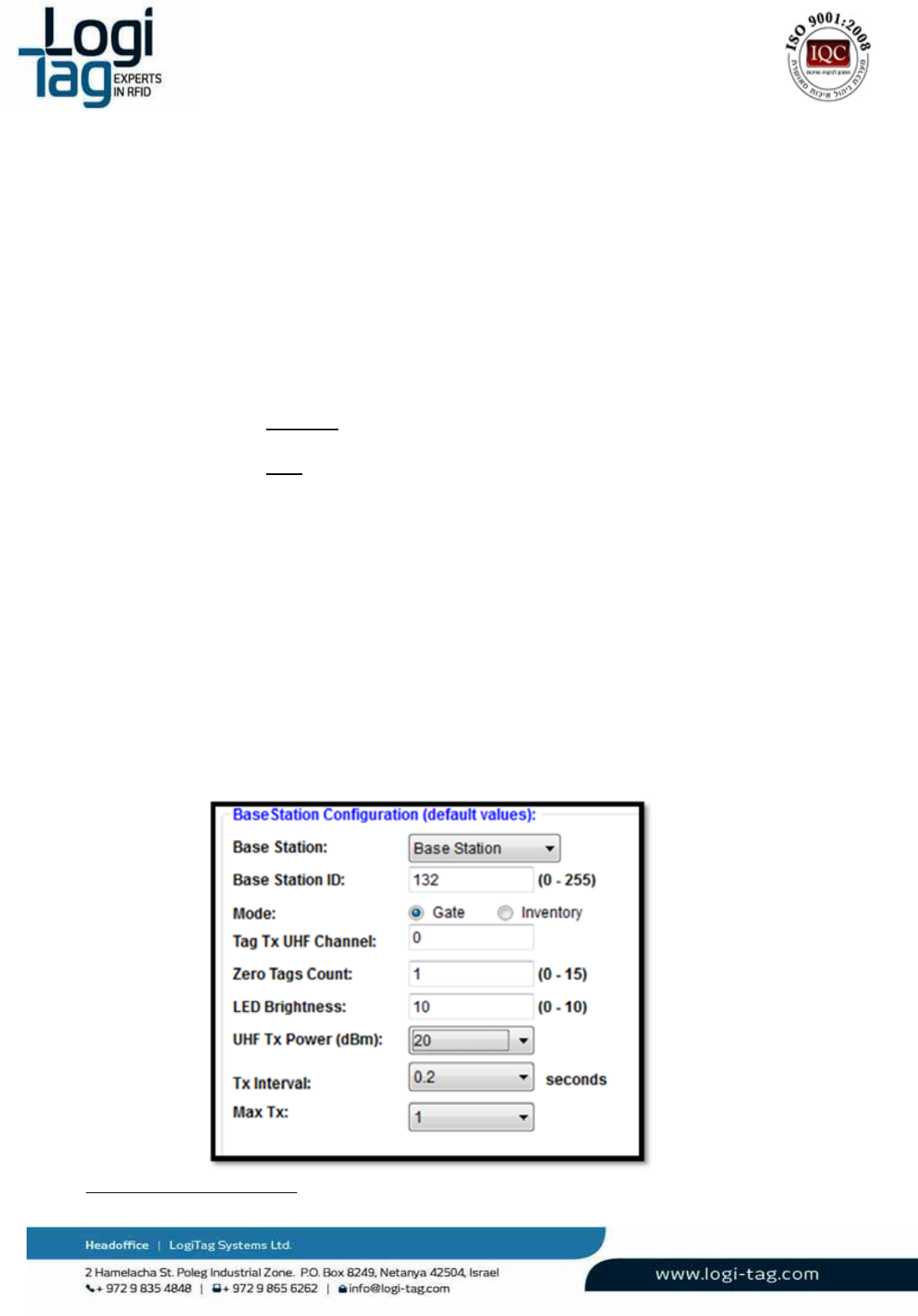
Withmorethan1Base‐StationDefined
Whenswitchingtothe“Base‐StationSetup”tabtheTechnician‐Stationapplicationwillretrievethe
valuesfromtheBase‐Stationdefinedasdefaultinthesystem.
ToretrievevaluesforanotherBase‐Stationandenablethem,userscanselectthedesiredBase‐Station
fromthe“BaseStation”dropdownlist.

LT‐D‐0211rev16
Page|56
6.4.6 RFzones(Lfantennas)configuration
EachGateLocatorincludes4portsofLF(Low‐Frequency,125KHz)antennas,usedforexcitingtags
(causingthemtotransmit).Thetagwillreporttothebase‐stationtheidentityoftheantennathat
excitedit,sotheBase‐Station\GateLocatorcanreportwherethetagislocated.
TheTechnician‐StationprovidesthesystemadministratorwiththeabilitytoconfiguretheBase‐Station’s
ports,specificallythefollowingparameters:
1.
Enable/Disabletheport–Thesystemadministratormaychoosetoenable1ormore
ports,dependingonthedeploymentrequired.
2.
LFTXPower–ThepowerinwhichtheBase‐StationtransmitstheLFsignalcanbefine‐
tunes,thusaffectingtherangeanddiameteroftheRF‐Zonecreatedfromtheantenna.
Thepowerisdeterminedinpercentage,atstepsof10%(10‐100%).
Inadditionthefollowingparameterscanbedetermined:
Antennaname–Forcontinence,theadministratorcanchangethedefaultnames
“port1”–“port4”tonamesthatbetterrepresentthelocationinwhichthe
antennaisinstalled,e.g.“meetingroom”,“Floor1elevators”etc.
TagUHFPower–Whenabasestationisexcitedthroughaspecificchannel,the
Base‐StationisabletorespondtothetagandmodifyitsUHFtransmissionpower.
Thisvalueisdeterminedindbm,between1(min)to20dbm(max,default).
LT‐D‐0211rev16
Page|57
6.4.7
AdvancedOperationalParameters
TheTechnician‐Softwareprovidesaninterfacetoenableconfiguringseveraladvancedoperational
parametersoftheBase‐Stations.Theseparametersshouldbeleftintheirdefaultvalue,unlessachange
isrequired.
PleaseconsultwithLogiTag’sSupportbeforechangingoneofthesevalues:
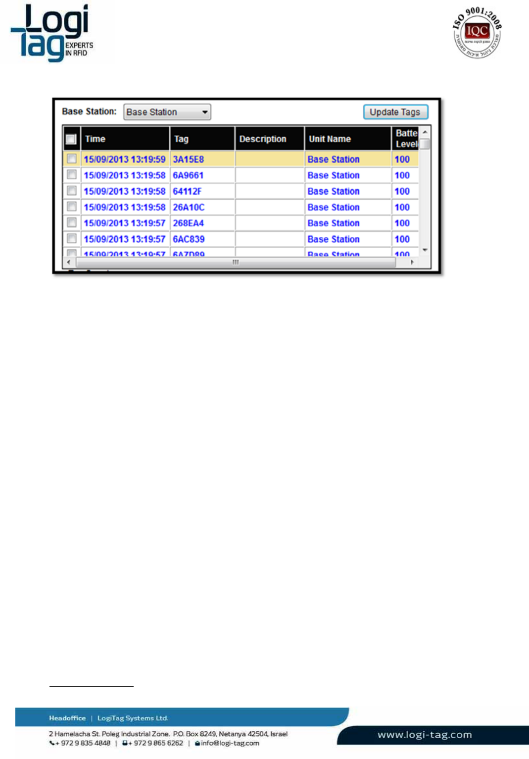
Base‐StationID–AuniqueidentifieroftheBase‐Stationinaspecificproject.The
defaultvalueisdeterminedinLogiTag’sduringproductioninaccordancewith
knownIDsalreadyactive.
Mode:
Inventory‐thismodedefinesthattheunitwillnotbeactiveuntilorderhasbeen
senttoperformaninventorycountfromthebasestation.
Gate–thismodedefinesthattheunitwillbeactiveandeverytagthatwillbe
locatedintheRFzoneswillbedetected.
TagTXUHFChannel(0‐3)‐ToenablebetterusageoftheUHFband,differentBase‐
Stationsmaybesettovariouschannels,thusreducingchancesofcollisions.
ZeroTagsCount–Anoperationalparametersusedintagsanti‐collisionalgorithm.
Default(andrecommended)valueis0(zero),highervalueswillincreaseBase‐
Station’schancestoreceivealltag,butatlowerspeed.
LEDBrightness–SetthebrightnessofLEDontheBase‐Station’sfrontpanel.Canbe
dimmedtoreducevisibilityinsomeinstallations.
UHFTXPower‐ definesthepowerthatthetagwilltransmittotheunitonce
detectedintheRFzones.
TXInterval–definestheamountoftransmitionthatthetagwilltransmittotheunit
persecond.
MaxTx‐definesthenumberoftransmitionthatthetagswilltransmittotheunit.
FinalizingtheSetupProcess

LT‐D‐0211rev16
Page|58
Uponcompletingsettingvaluestoallrelevantparameters,theadministratorcanchoosetosavesettings
totheBase‐StationbypressingtheSETcommand.
Thefollowingmessageshouldappeartoinformtheuserthattheoperationwascompletedsuccessfully:
6.4.8 “TagsSetup”Tab
TheTagsSetuptabprovidesthetooltoconfiguretagswithvariousoperationalparameters,primarilyto
enablevarioussensorsandtunethemtospecificapplications.
SelectingaTagforConfigurationSetup
Inordertoconfigureatag,itmustbeexcitedthroughLFantennaandhavecommunicationwithaUnit:
SelecttheBaseStationyouareabouttouseforexcitingthetag,fromthe“SelectBaseStation”
dropdownlist.ItisrecommendedtouseLogiTag’stechnicianHardwareforthispurpose,asit
includesBase‐StationhardwareandLFantennainasingleenclosure.
Selecttheantennaportthetagwillinfrontofduringthesetupprocess,fromthe“SelectLocation”
dropdownlist.
PlacethetaginfrontoftheselectedBase‐Station\Antenna,andpresstheUpdateTagsbutton–the
tag(orseveraltags)shouldappearinthelist.
LT‐D‐0211rev16
Page|59
Clickthecheckboxofeverytagyouwishtoprograminthecurrentsession
6.4.9
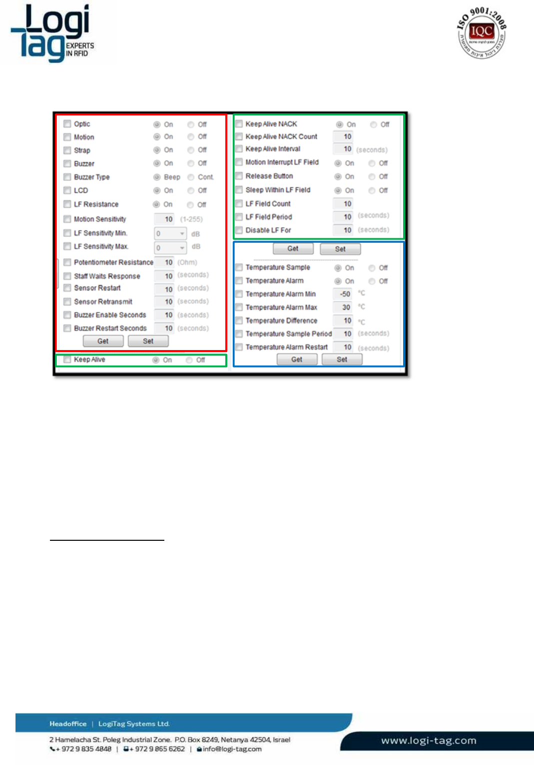
Sensors&tagdefinitions
Thetampersensorandstatusbuttonindicationsforexample,needtobeenabledinsupportedtags.
ToEnablesensorsordefineotherparametersperformthefollowingsteps:
Notethatagroupofparameterscanbesettogetherinonecommandaccordingtothegroupof
commands(eachgroupismarkedbyadifferentcolor).
1.
PresstheUpdatebuttonandselectthetagstoprogramfromthelist.
2.
ChangetheTampersoftwareswitchtothedesiredstatus.
3.
PresstheSendbuttontomakethechangeinthetags.
4.
Ensureyoureceivetheconfirmationmessagefromthesoftware
5.
PresstheGetbuttontoreadtheactualstatusfromthetag.
Alltagparameters:
LT‐D‐0211rev16
Page|60
ManagingTemperatureSensor:
TagswithtemperaturesensorcanmonitorthetemperaturesensedbytheexternalPT‐100unit.
Thetagsincludethefollowinglogic:
Monitoringtemperaturethresholds:Atagcanbeconfiguredtomonitorthetemperature
comparedwithaMinimumand/orMaximumthreshold.
SampleperiodReading:Thetagcansamplethetemperatureinfixedintervalandsendthevalue
toamainserver,wherethresholdscanbemonitored.
ToSetMinimumAnd/OrMaximumThresholds
PreventingLFdistractions
InsomeapplicationandenvironmenttheLFsignalmaysufferfrominterferencesthatcancause2main
issues:
Unwantedtagactivation(suchasactivatingthebuzzerinthetag)
Unwantedtagexcitingthatcanbecausedfromelectricaldistractionssuchasserversorcomputers.
TofilterunwantedtagactivationactivatestheLFResistanceparameterinordertoavoidunwantedtag
exciting.
LT‐D‐0211rev16
Page|61
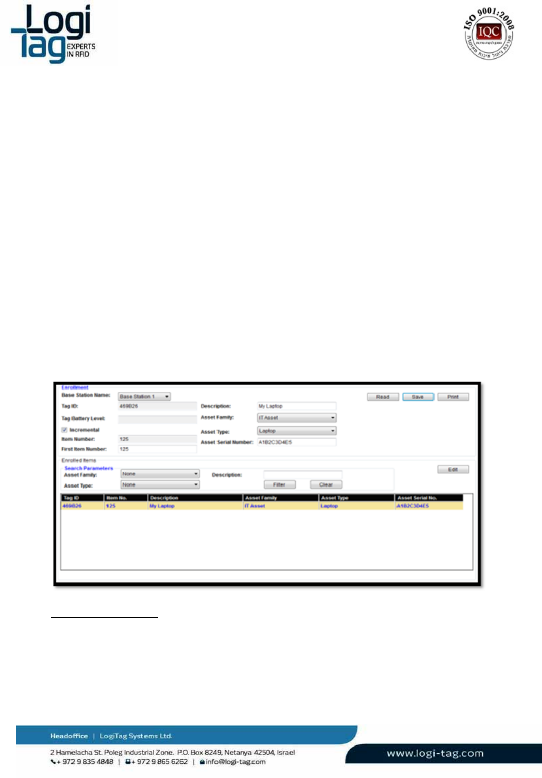
6.4.10 “Enrollment”Tab
TheEnrollmenttabdeliversasimpletooltodefineassets/peopleandassociatethemwithatag,
enablingmanagementofasset/peopleratherthantags.
EnrollinganAsset/People
1.
SelecttheBase‐StationfromtheBaseStationNamedropdownlistthroughwhichatagwillbe
readintheprocess
2.
PresstheReadbuttontogetthetagnumberfromtheBase‐Station.Thetag’snumberwill
populatetheTagIDparameter.
3.
SelecttheAssettype
a.
SelecttheAssetfamilyfromthedropdownlist
b.
Selecttheassettypefromthedropdownlist
c.
Enteradescriptionfortheasset
d.
Enteraserialnumber/IDnumberfortheasset(ifapplicable)
4.
Usean“Assetnumber”toenableeasiermanagementwithoutlongtag–IDs
5.
Tomanuallyprovideanumbertoeachnewasset,enteranumberattheItemNumber
parameter.
6.
Touseanitemnumberthatautomaticallyincrementsbetweenassets
a.
ChecktheIncrementalcheckbox
b.
EntertheFirstItemNumbervalue
7.
PresstheSavebuttontofinishtheoperation,savetheassetanditsassociatedtag,andproceed
toenrollmentofanewasset.
ViewingEnrolledAssets
TheEnrollmentTabalsodeliversthetoolstomanagetheassetsandmodifytheirdetails.
ToSearchforaspecificAsset
1.
SelecttheAsset‐FamilyandAsset‐Typetonarrowdownthelistofassets.
2.
Locatetheassetyouaresearchingforinthelistandclickonittoselect.
3.
PresstheEditbuttontohaveitsdetailsappearonthetoppartofthetab.

LT‐D‐0211rev16
Page|62
4. Editthedetailsasrequired,includingassociationtoadifferenttag,andpressSavewhenyouare
done.
LT‐D‐0211rev16
Page|63
6.4.11
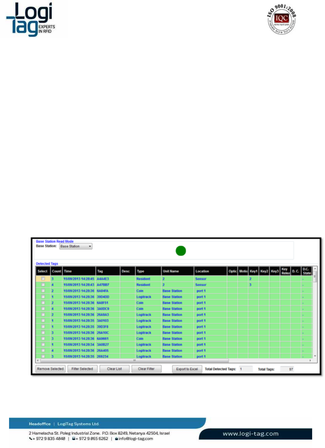
“Detection”Tab
TheDetectiontabshowsalistoftagsreceivedbyallBase‐Stationscurrentlyconnected(andselected)
withtheTechnician‐Stationsoftware.
DetectedTagsList
Theinformationshowninthelistofdetectedtags:
Count–Thenumberofmessagesreceivedfromatagincurrentsession
Time–Timeanddateoflastmessagereceived
Tag–IDofthetagbeingreceived
Description–Ifthetagisenrolledwithanasset,theassetdescriptionisdisplayed.
Location–Showsthereasonoftransmissionofthetag.
o
TagtransmittedbecauseitwasexcitedwhenlocatednearoneoftheLF‐Antennas(RF‐
Zones),theantennanamewillbedisplayed
o
Tagtransmittedbecauseofsensor,buttonorexternalinput.Theexactreasonwillbe
displayed.
Tamper–ShowsTrueifthetag’sTampersensorreportedatamperevent
Motion‐ShowsTrueifthetag’sMotionsensorreportedatamperevent
Input‐ShowsTrueorFalseifthetagtransmittedduetoanevenintheexternalinputport.Ifthe
currentstatusisON,theindicationisTrue,otherwiseFalse.
Key1–Key3–IndicatedTrueifabuttonwaspressedonthetag.
TemperatureAlarm–IndicatedTrueifathresholdsetinthetagwasexceeded
Temperature–Showsmeasuredtemperatureinthetag’ssensor
TagBattery–Thetagindicatesitsbatterystatuswitheachtransmission
ToFilterSelectedTagsandManageFilteredLists
LT‐D‐0211rev16
Page|64
1.
Selectthecheckboxoftagsyouwishtomanage
2.
PresstheRemoveSelectedbuttontofilterouttheselectedtags.Thesetagswillnotbe
showninthelistuntilfiltersettingsarecleared
3.
PresstheFilterSelectedbuttontofilteroutalluncheckedtags.Uncheckedtagswillnotbe
shownuntilthefiltersettingsarecleared.
4.
PresstheClearFilterbuttontorestorebackalltagsfilteredout.
5.
PresstheClearListbuttontoremovealltagsfromthelistandhaveitre‐populatedwith
newlyreceivedtagsonly.
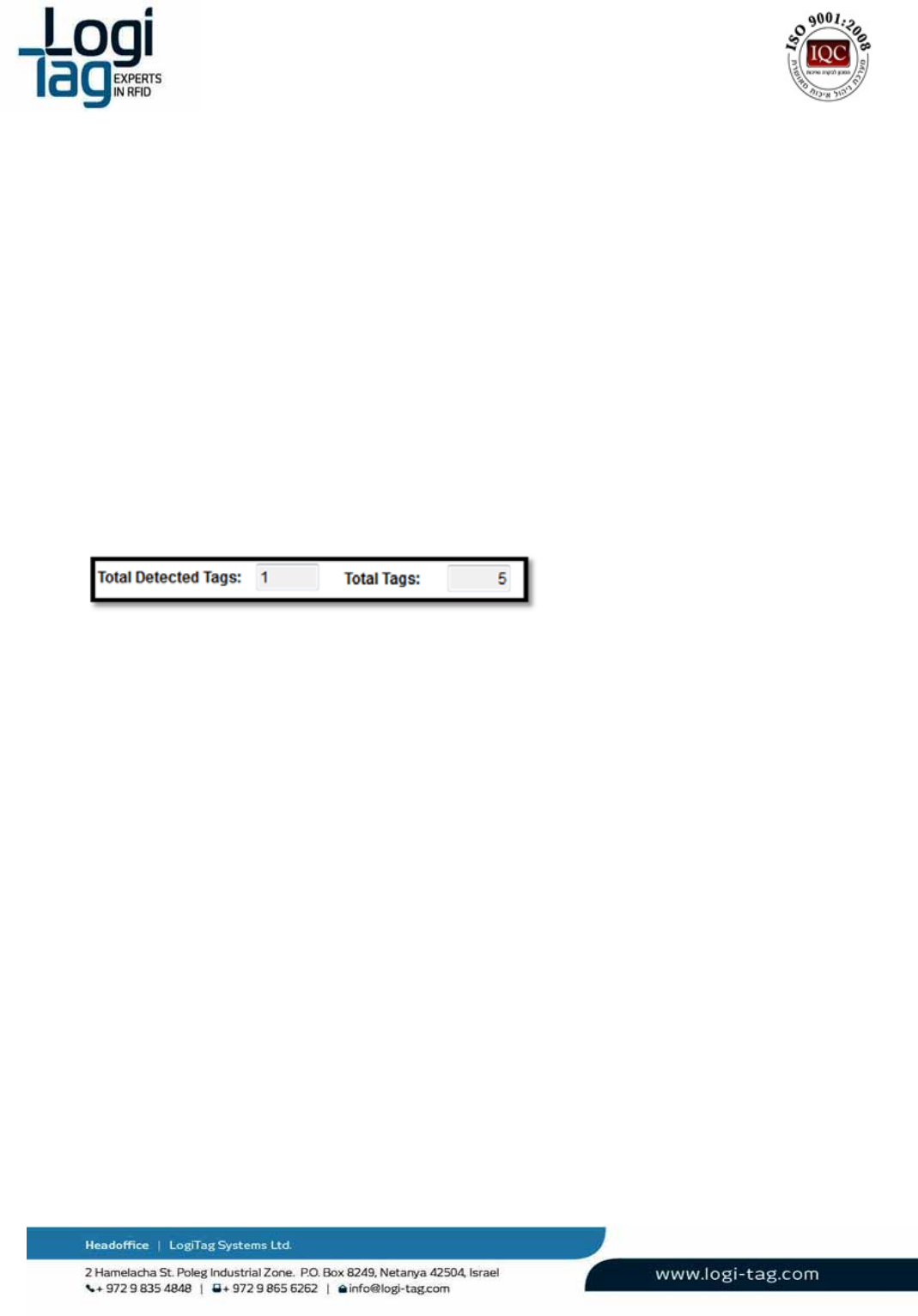
DetectedTagsIndications
TheDetectiontabshows2indicationsaboutdetectedtags
Tagdetected–agreencircleisshowingforeverytagmessagedetected.
TotalTag–Showsthetotalnumberoftagscurrentlyshowninthelist
Detectedtags–ShowsthenumberoftagsdetectedbytheBase‐Stationinitslast
scan.
LT‐D‐0211rev16
Page|65
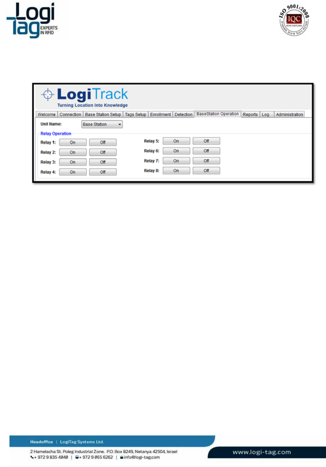
6.4.12
“Base‐StationOperation”Tab
TheBaseStationOperationtabenablestheusertotoggletheUnit'sdry‐contactrelays.
Totoggleadry‐contactrelay
1.
SelecttheBase‐Stationfromthedrop‐downlist
2.
PresstheOnbuttonforeveryrelayyouwishtotoggleON
3.
PresstheOffbuttonaccordingly.
LT‐D‐0211rev16
Page|66
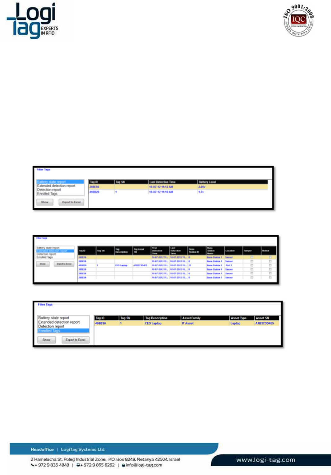
6.4.13 “Reports”Tab
TheReportstabdeliversseveraladministrativereportsthatshowsindepthdetailedinformationtohelp
managetheLogiTracksystem.
OperatingtheReportsTab
ToIssueareport
1.
Selectareportfromthelistshownontheleftpanel
2.
PresstheShowbuttontodisplaythereport’sresults
3.
PressExportToExceltohavetheresultsfromthegridexportedtoanExcelfile
4.
SelectthepathtosavetheExcelfileandpressSave
AvailableReports
BatteryStateReport‐ShowsalltagsdetectedbytheTechnicianstationandtheirlatestbatterystatus.
ExtendedDetectionReport–ShowsadetailedlistofalltagsreceivedbytheTechnician‐Station,thedate
&timeoftheirfirstandlastdetection,knownsensors/inputsindicationsandotherdetailedinformation.
EnrolledTags–Showsalistofallenrolledassetsinthesystem,theirdetailsandassociatedtags.

LT‐D‐0211rev16
Page|67
6.4.14 “Log”Tab
TheLogtabdisplaysrawdatareceivedfromBase‐StationsconnectedtotheTechnician‐Station.The
contentoftheinformationdisplayedintheLogtabissavedtofilesstoredinLogsdirectoryatthe
installationfolderoftheapplication(C:\ProgramFiles\LogiTag\TechnicianStationbydefault).
LT‐D‐0211rev16
Page|68
7.
Troubleshooting
7.1 Connectivityissues
7.1.1 Softwareconnection
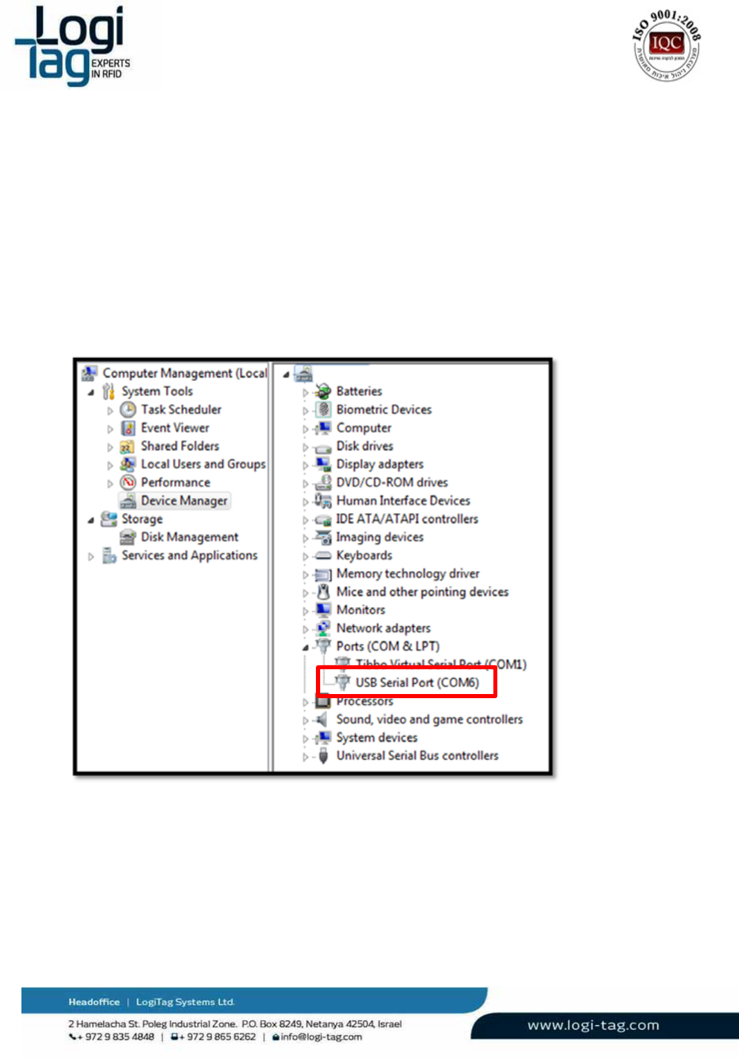
Ifasoftwareconnectionisnotable,check:
CheckthattheunitisconnectedtothepowerandthatLEDlightsareon.
Checkthatthecorrectcomportisselected.Toviewthecorrectcomportenterthedevicemanager
RightclickonMyComputer‐Manage–DeviceManger
Ontherightscreenthecomportnumberwillappear(thenumberchangesfromonecomputerto
other)
1.
Whenfinishedgobacktothetechniciansoftwareandchoosethecorrectcomport

LT‐D‐0211rev16
Page|69
7.1.2 Driverinstallation
IftheUSBdriverisnotinstalledproperlyonthedevicemanagerscreenanotificationofanUnknown
devicewillappear:
1.
Inthiscase,installthedriveragainandcheckdriverstatusagainbyperformingthenextsteps:
2.
Rightclickontheunknowndeviceandclickonupdatedriversoftware
3.
Onthebrowseforthedriversoftwareonyourcomputer,clickonthebrowsebuttonand
browsetothefolderwhichcontainsthedriverprovidedontheCDprovidedfromLogiTag.

LT‐D‐0211rev16
Page|70
7.2 Hardwareissues
7.2.1 LFsignaldoesnottransmits
IncasethattheunitdoesnottransmitstheLFsignalcheck:
Installtionofthecablemustbeseparatedfromcommunicationandelectricity
infrastructure
Donotconnectorcross2cables
Makesurethatcablepolarityisequalonbothendsasdescribedinthepicture
CheckconfigurationthroughtechnicianstationasdescribedonsectionRFzones
(Lfantennas)configuration
CheckLEDlightontheantenna‐openthetopoftheantenna'sboxandcheckifthe
LEDlightinsideison.Incasethelightisoff,checkthepolarityonbothendsorswitchthe
antenna
7.2.2 Unitdoesn’tturnon
Incasethattheunitdoesnotturnoncheck:
1.
Thepowersupplyadaptorisconnected
2.
Theconnectorthatconnectstotheunitisconnectedproperlyandwiresareconnected.
3.
Ifstepsnumber1and2doesnothelpchangethepowersupplyadaptor
7.2.3 Theunitisonbutnoresponse
IncasetheunitisonandallLEDlightsareonbuttheunitdoesnotdetectRFIDtagsonLFfieldperform
thenextsteps:

LT‐D‐0211rev16
Page|71
1. CheckthattheLFantennaisactivatedasdescribedonsection‐LFsignaldoesnottransmits
2. CheckthatallUHFantennasareconnectedtotheunit(UHF1‐4)
3. Disconnectthepoweradaptorfromtheunitandconnectback
Whentheunitisbackonwaitfor1minuteforallcomponentstoreset.
Clickonconnectthroughthetechniciansoftware
7.2.4 Tagdoesnotrespond
Incaseatagdoesnotrespondpleaseperformstepsonchapter‐LFsignaldoesnottransmits
Incasethestepabovedidnothelp,connectasecondantennatoadifferentportandchecktag
response.Thischeckisincasethetagisconfiguredtostoptransmittingafteracertainamountof
timeneartheLFantenna.Thesecondantennashouldreactivatethetag.
Notethatiftheparameter"sleepwithinLFfiled"isonitmightbethatthetaghasbeendetecteda
largenumberoftimeneartheantennaandhasbeendisabledforaperiodoftimedefined.
Ifthestepsabovedoesnothelpperformstepsonsection‐Theunitisonbutnoresponse

LT‐D‐0211rev16
Page|72
8. RadioApprovals
8.1 BaseStation\GateLocator\GateExciterGPRS\4ChannelExciter
ThefollowingsystemssharethesameFCCID:
Basestation
GateLocator
GateExciterGPRS
4ChannelExciter
8.1.1 USA(FCC)
‐ FCCID:Z97Z97LTG2‐01
Note:ThisequipmenthasbeentestedandfoundtocomplywiththelimitsforaClassB
digitaldevice,pursuanttopart15oftheFCCRules.Theselimitsaredesignedtoprovide
reasonableprotectionagainstharmfulinterferenceinaresidentialinstallation.This
equipmentgenerates,usesandcanradiateradiofrequencyenergyand,ifnotinstalledand
usedinaccordancewiththeinstructions,maycauseharmfulinterferencetoradio
communications.However,thereisnoguaranteethatinterferencewillnotoccurina
particularinstallation.Ifthisequipmentdoescauseharmfulinterferencetoradioor
televisionreception,whichcanbedeterminedbyturningtheequipmentoffandon,the
userisencouragedtotrytocorrecttheinterferencebyoneormoreofthefollowing
measures:
Reorientorrelocatethereceivingantenna.
Increasetheseparationbetweentheequipmentandreceiver.
Connecttheequipmentintoanoutletonacircuitdifferent
Fromthattowhichthereceiverisconnected.
Consultthedealeroranexperiencedradio/TVtechnicianForhelp.
Warning:
Changesormodificationstothisequipmentnotexpresslyapprovedbytheparty
responsibleforcompliance(LogiTagSystemsLtd.)couldvoidtheuser’sauthorityto
operatetheequipment.

LT‐D‐0211rev16
Page|73
TocomplywithFCCRFradiationexposurelimitsforgeneralpopulation,theantenna(s)usedfor
thistransmittermustbeinstalledsuchthataminimumseparationdistanceof20cmismaintained
betweentheradiator(antenna)andallpersonsatalltimesandmustnotbeco‐locatedor
operatinginconjunctionwithanyotherantennaortransmitter.
8.2 OneChannelExciter
8.2.1 USA(FCC)
‐ FCCID:Z97LTG2‐04
Note:ThisequipmenthasbeentestedandfoundtocomplywiththelimitsforaClassB
digitaldevice,pursuanttopart15oftheFCCRules.Theselimitsaredesignedtoprovide
reasonableprotectionagainstharmfulinterferenceinaresidentialinstallation.This
equipmentgenerates,usesandcanradiateradiofrequencyenergyand,ifnotinstalledand
usedinaccordancewiththeinstructions,maycauseharmfulinterferencetoradio
communications.However,thereisnoguaranteethatinterferencewillnotoccurina
particularinstallation.Ifthisequipmentdoescauseharmfulinterferencetoradioor
televisionreception,whichcanbedeterminedbyturningtheequipmentoffandon,the
userisencouragedtotrytocorrecttheinterferencebyoneormoreofthefollowing
measures:
Reorientorrelocatethereceivingantenna.
Increasetheseparationbetweentheequipmentandreceiver.
Connecttheequipmentintoanoutletonacircuitdifferent
Fromthattowhichthereceiverisconnected.
Consultthedealeroranexperiencedradio/TVtechnicianForhelp.
Warning:
Changesormodificationstothisequipmentnotexpresslyapprovedbytheparty
responsibleforcompliance(LogiTagSystemsLtd.)couldvoidtheuser’sauthorityto
operatetheequipment.

LT‐D‐0211rev16
Page|74
8.3 RemoteDoorIndicator
8.3.1 USA(FCC)
‐ FCCID:Z97LTG2‐05
Note:ThisequipmenthasbeentestedandfoundtocomplywiththelimitsforaClassB
digitaldevice,pursuanttopart15oftheFCCRules.Theselimitsaredesignedtoprovide
reasonableprotectionagainstharmfulinterferenceinaresidentialinstallation.This
equipmentgenerates,usesandcanradiateradiofrequencyenergyand,ifnotinstalledand
usedinaccordancewiththeinstructions,maycauseharmfulinterferencetoradio
communications.However,thereisnoguaranteethatinterferencewillnotoccurina
particularinstallation.Ifthisequipmentdoescauseharmfulinterferencetoradioor
televisionreception,whichcanbedeterminedbyturningtheequipmentoffandon,the
userisencouragedtotrytocorrecttheinterferencebyoneormoreofthefollowing
measures:
Reorientorrelocatethereceivingantenna.
Increasetheseparationbetweentheequipmentandreceiver.
Connecttheequipmentintoanoutletonacircuitdifferent
Fromthattowhichthereceiverisconnected.
Consultthedealeroranexperiencedradio/TVtechnicianForhelp.
Warning:
Changesormodificationstothisequipmentnotexpresslyapprovedbytheparty
responsibleforcompliance(LogiTagSystemsLtd.)couldvoidtheuser’sauthorityto
operatetheequipment.

LT‐D‐0211rev16
Page|75
8.4 StaffTag
8.4.1 USA(FCC)
‐ FCCID:Z97LTT‐08
Note:ThisequipmenthasbeentestedandfoundtocomplywiththelimitsforaClassB
digitaldevice,pursuanttopart15oftheFCCRules.Theselimitsaredesignedtoprovide
reasonableprotectionagainstharmfulinterferenceinaresidentialinstallation.This
equipmentgenerates,usesandcanradiateradiofrequencyenergyand,ifnotinstalledand
usedinaccordancewiththeinstructions,maycauseharmfulinterferencetoradio
communications.However,thereisnoguaranteethatinterferencewillnotoccurina
particularinstallation.Ifthisequipmentdoescauseharmfulinterferencetoradioor
televisionreception,whichcanbedeterminedbyturningtheequipmentoffandon,the
userisencouragedtotrytocorrecttheinterferencebyoneormoreofthefollowing
measures:
Reorientorrelocatethereceivingantenna.
Increasetheseparationbetweentheequipmentandreceiver.
Connecttheequipmentintoanoutletonacircuitdifferent
Fromthattowhichthereceiverisconnected.
Consultthedealeroranexperiencedradio/TVtechnicianForhelp.
ThisdevicecomplieswithPart15oftheFCCRules.
Operationissubjecttothefollowingtwoconditions:
(1)Thisdevicemaynotcauseharmfulinterference,and
(2)Thisdevicemustacceptanyinterferencereceived,includinginterferencethatmaycause
undesiredoperation.
Warning:
Changesormodificationstothisequipmentnotexpresslyapprovedbytheparty
responsibleforcompliance(LogiTagSystemsLtd.)couldvoidtheuser’sauthorityto
operatetheequipment.
LT‐D‐0211rev16
Page|76
8.5 ResidentTag
8.5.1 USA(FCC)
‐ FCCID:Z97LTT‐03
Note:ThisequipmenthasbeentestedandfoundtocomplywiththelimitsforaClassB
digitaldevice,pursuanttopart15oftheFCCRules.Theselimitsaredesignedtoprovide
reasonableprotectionagainstharmfulinterferenceinaresidentialinstallation.This
equipmentgenerates,usesandcanradiateradiofrequencyenergyand,ifnotinstalledand
usedinaccordancewiththeinstructions,maycauseharmfulinterferencetoradio
communications.However,thereisnoguaranteethatinterferencewillnotoccurina
particularinstallation.Ifthisequipmentdoescauseharmfulinterferencetoradioor
televisionreception,whichcanbedeterminedbyturningtheequipmentoffandon,the
userisencouragedtotrytocorrecttheinterferencebyoneormoreofthefollowing
measures:
Reorientorrelocatethereceivingantenna.
Increasetheseparationbetweentheequipmentandreceiver.
Connecttheequipmentintoanoutletonacircuitdifferent
Fromthattowhichthereceiverisconnected.
Consultthedealeroranexperiencedradio/TVtechnicianForhelp.
ThisdevicecomplieswithPart15oftheFCCRules.
Operationissubjecttothefollowingtwoconditions:
(1)Thisdevicemaynotcauseharmfulinterference,and
(2)Thisdevicemustacceptanyinterferencereceived,includinginterferencethatmaycause
undesiredoperation.
Warning:
Changesormodificationstothisequipmentnotexpresslyapprovedbytheparty
responsibleforcompliance(LogiTagSystemsLtd.)couldvoidtheuser’sauthorityto
operatetheequipment.

LT‐D‐0211rev16
Page|77
9. Powersupplyreuiermants
Forsupplyingpowertothedifferentsystemsonemyuse2differentoptions:
‐ LocalLimitedpowersupplysource
‐ Mainpowersupplyunitforseveralunits
9.1 Limitedpowersource:
Whenusinglocalpowersupply,useLPScertifiedtypeequivalentto:
a. EDACp/nEA10721B-2404
b. MEANWELLp/nGS60A24
9.2 Mainsupplynetwork:
Whenusingmaimspowersupply,forsupplyingpowertoseveralunits,youmustfollowthe
followinginstallationrequirements:
a. Usemainpowersupply24Vwithmaximumoutputof40A
b. Theunitmustbecertifiedaccordingtolocalauthority'sroles.
c. Makesuretheunithasinternaloutputcircuitbreakerwithshortcircuitandovercurrent
protection.IfnotconnectexternalcertifieddoublepoleDCcircuitbreaker(astheabove)at
ratingsmaximumallowedoutputcurrentofthepowersupply(equalorlowerthanthe
powersupplycurrentoutputratings).
d. Whenconnectingacablebetweenpowersupplytoasystem,useacablethatcanstandthe
maximumallowedoutputcurrentfromthepowersupply(accordingtolocalauthority's
rules)forexample:
‐ For40Acurrentuse2*10mm2cuppercable
‐ For30Acurrentuse2*10mm2cuppercable
‐ For25Acurrentuse2*6mm2cuppercable
‐ For20Acurrentuse2*4mm2cuppercable
e. ToeachendunitconnectacertifieddoublepoleDCcircuitbreakerwithshortcircuitand
overcurrentprotectionwithratingsaccordingtothefollowinglist:
‐ Basestation‐‐‐‐6A.use2*1mm2cuppercable
‐ GateLocator/4Channelexciter‐‐‐‐6A.use2*1mm2cuppercable
‐ OneChannelExciter‐‐‐‐2A.use2*0.5mm2cuppercable
‐ RemoteDoorIndicator‐‐‐‐2A.use2*0.5mm2cuppercable

LT‐D‐0211rev16
Page|78
f. Usethefollowingcircuitbreaker,orequivalent;
2A:
‐ EATONp/nFAZ‐C2/2‐NA
‐ ABBp/nS202‐C2
6A:
‐ EATONp/nFAZ‐C6/2‐NA
‐ ABBp/nS202‐C6
Connectthecircuitbreakerbetweentheendunitandthemainpowersupply.